Embed Size (px)
Citation preview

c
CHAPTER 5 CLUTCHES
Clutch Service Tools ........... ............ ... 5.1
Drive Clutch Weight Identification ... ......... . .. 5.2-5.4
Drive Clutch Spring Rates . . . . ..... . . .......... 5.5
Drive Clutch Spring Data ...................... 5.6
Driven Clutch Spring Data I Rates ... . . ..... . .. . 5.7
P-85 Drive Clutch Exploded View ............... 5.8
P-85 Driven Clutch Exploded View .............. 5.9
P-90 Drive Clutch Exploded View .... . ...... . .. . 5.10
P-90 Driven Clutch Exploded View ........... ... 5.11
Drive Clutch Operation ........................ 5.12-5.13
Driven Clutch Operation ....................... 5.14
Drive Clutch Identification andRemoval ......... . 5.15
Drive Clutch Disassembly and Inspection . . ...... 5.16-5.17
Spider Roller Removal ........................ 5.18
Roller Installation .. . . . .... .. . . ...... ........ .. 5.18-5.19
Spider Assembly ...... ................... .... 5.19-5.20
Drive Clutch Assembly ... .... . . . . . ..... . .. .... 5.21 -5.22
Drive Clutch Installation ....................... 5.22-5.23
Spider Indexing ...................... . . . ..... 5.24
Driven Clutch Removal ........................ 5.25
Driven Clutch Disassembly .................... 5.26-5.27
Driven Clutch Assembly ........... ............ 5.28-5.30
Helix Angles and Effects ....................... 5.29
Driven Clutch Installation . .... ... . . . ........... 5.31
Drive Belt Information ......................... 5.32
Drive Belt Inspection I Troubleshooting .......... 5.33
Drive Belt Deflection .......................... 5.34-5.35
Clutch Offset/Alignment ...... ..... .. .......... 5.36-5.37
Torque Stop Adjustment .. ............. . . .. .. .. 5.37
Belt to Sheave Clearance ...................... 5.38
Clutch Bushing Replacement - P-85 ............. 5.39-5.44
Clutch Bushing Replacement - P-90 . ............ 5.45-5.52
Troubleshooting .............................. 5.53-5.55

)
_)
·_)

c
A WARNING
CLUTCHES Service Tools
All drive clutch maintenance, disassembly and assembly must be performed only by an authorized Polaris dealer who has attended current model Dealer Service Seminars, has received a certificate of completion, and displays the Polaris Servicing Dealer decal.
Because of the critical nature and precision balance incorporated into the drive clutch, it is absolutely essential that no attempt at clutch disassembly and/or repair be made without factory authorized tools and service procedures.
Essential Drive Clutch Tools
Refer to the Service Tool Catalog (PN 9914681) for photos and descriptions of all tools. A tool catalog update is available through the Polaris parts department. The part number is 9915235.
Description Part Number Offset Alignment Tool- 21/32" (1 .7 em) P-90 Clutches ...... . . 2870914 Offset Alignment Tool - 5/8" (1.6 em) P-85 Clutches . . . . . . . . . . . 2870426 T-Handle Drive Clutch Puller (Large Shaft ID) . . . . . . . . . . . . . . . . 2870506 Drive Clutch Puller 14mm (Small Shaft ID) . . . . . . . . . . . . . . . . . . . 2871855 Drive Clutch Puller - '99 550 Fuji Engines . . . . . . . . . . . . . . . . . . . 2872084 Drive Clutch Puller- '99 700/800 XCR . . . . . . . . . . . . . . . . . . . . . . 2872085 Strap Wrench . . . . . . . . . . . . . . . . . . . . . . . . . . . . . . . . . . . . . . . . . . . . 2870336 Replacement Strap for 2870336 . . . . . . . . . . . . . . . . . . . . . . . . . . . . 2870389 Spider Spanner Nut Driver (Jam Nut) . . . . . . . . . . . . . . . . . . . . . . . 2870338 Spider Removal I Installation Tool . . . . . . . . . . . . . . . . . . . . . . . . . . 2870341 Holding Fixture . . . . . . . . . . . . . . . . . . . . . . . . . . . . . . . . . . . . . . . . . . . 2871358 Holding Fixture Tab . . . . . . . . . . . . . . . . . . . . . . . . . . . . . . . . . . . . . . . 5130518 Tapered Reamer . . . . . . . . . . . . . . . . . . . . . . . . . . . . . . . . . . . . . . . . . 2870576 Spider Button Tool . . . . . . . . . . . . . . . . . . . . . . . . . . . . . . . . . . . . . . . . 2870985 Clutch Bushing Rebuild Tool Kit (P-85/P90) . . . . . . . . . . . . . . . . . 2871025 P-85 Drive Clutch Compression Tool . . . . . . . . . . . . . . . . . . . . . . . . 2870984 Driven Clutch Puller (P-90) . . . . . . . . . . . . . . . . . . . . . . . . . . . . . . . . 2871 056 Torque Wrench, 250 ft. lb. . . . . . . . . . . . . . . . . . . . . . . . . . . . . . . . . . Commercially Available Torque Wrench, 0-200 in. lb. . . . . . . . . . . . . . . . . . . . . . . . . . . . . . . . Commercially Available Clutch Compression Tool . . . . . . . . . . . . . . . . . . . . . . . . . . . . . . . . . . 8700220 Clutch Holding Wrench . .... .. . ... ..... . . . ......... . ... . . .. 9314177 SLP Button Tool . . . . . . . . . . . . . . . . . . . . . . . . . . . . . . . . . . . . . . . . . . 871601 0 r SLP Clutch Sheave Clamp Tool . . . . . . . . . . . . . . . . . . . . . . . . . . . . 8716020
Polaris Industries Inc. 5.1 10/98

CLUTCHES Drive Clutch Weight Identification - Actual Size
u w Gram Weight: 34 ± 1 Gram Weight: 37.5 ± 1 G - (8 Modified)
PN 56301 07 PN 56301 o9 Gram Weight: 41.5 ± 1
02
02 Gram Weight: 49 ± 1
PN 5630225
04
0 Gram Weight: 51
PN 5610088
PN 5630063
0 Gram Weight: 53± 1
PN 5630174
04 M1 (Modified) K1 Gram Weight: 57.5 ± 1 Gram Weight: 46.0 ± 1 Gram Weight: 39 ± 1
PN 5630229 PN 5630301 PN 5630144
10/98 5.2
N
A Gram Weight: 47.5 ± 1
PN 5630080
03
03 Gram Weight: 32.5 ± 1
PN 5630227
P1 Gram Weight: 42 ± 1
PN 5630089
Polaris Industries Inc.
J

(
J1 Gram Weight: 44 ± 1
PN 5630065
08 Gram Weight: 47.5 ± 1
PN 5630245
10M Bushed Gram Weight: 49.5 ± 1
PN 1321528
Polaris Industries Inc.
CLUTCHES Drive Clutch Weight Identification - Actual Size
05 06 Gram Weight: 53.5 ± 1 Gram Weight: 50± 1
PN 5630234 PN 5630243
15 10 Bushed Gram Weight: 55.5 ± 1 Gram Weight: 51.5 ± 1
PN 5630274 PN 1321526
10M 8
1OM Blue Bushed Gram Weight: 47.5 ± 1
PN 1321529
1OM Red Bushed Gram Weight: 44 ± 1
PN 1321 530
5.3
07
07 Gram Weight: 52± 1
PN 5630244
1 OM-W Bushed Gram Weight: 46 ± 1
PN 1321527
10/98

CLUTCHES Drive Clutch Weight Identification - Actual Size
1 0-AL Bushed Gram Weight: 53± 1
PN 1321531
1 0-60 Bushed Gram Weight: 60
PN 1321587
1 0-54 Bushed Gram Weight: 54±1
PN 1321685
10/98
1 0-66 Bushed Gram Weight: 66
PN 1321584
1 0-58 Bushed Gram Weight: 58
PN 1321588
s
S53B Gram Weight:49 ±1
PN 1321730
1 0-64 Bushed Gram Weight: 64
PN 1321585
10A Bushed Gram Weight: 55
PN 1321589
s
S53R
1 0-62 Bushed Gram Weight: 62
PN 1321586
1 0-56 Bushed Gram Weight: 56±1
PN 1321684
s 55R
S55R Gram Weight:51 ±1
PN 1321731 Gram Weight:53 ±1
PN 1321759
5.4 Polaris Industries Inc.

r
( _ (/) c z :J 0 a. -w (.) a: 0 LL
CLUTCHES Drive Clutch Spring Hates
The following chart will aid in the setup and balance of engine RPM power curves for special converter tuning requirements such as high operating altitude, heavy loads, mountainous terrain, etc.
Drive Clutch Spring Compression Rate Chart
Drive Clutch Spring Compression Rate Chart 340
320
300
P-90 TRAVEL 280 P-85 TRAVEL
260
240
220
200
180
160
Almond ---- 7041566
Dark Blue --- .<. 7041526 ~Dark Blue/White
7041781
-----Plain 7041021
~'----:::~""""--..,..-.=-:f--""7"'"-----+--7""----\t:::-t------ Black
40
20--~~-----+--------+-------~--------~------~~
o~-------r------~------+-------r-------ir-2.50 2.25 2.00 1.75 1.50 1.25 1.19
COMPRESSED SPRING LENGTH (INCHES)
Polaris Industries Inc. 5.5
7041022
7041157 ATVonly
10/98

CLUTCHES Drive Clutch Spring Data
PART NUMBER COLOR CODE WIRE DIAMETER FREE LENGTH +1- .125"
7041021 Clear .157" 4.38"
7041022 Black .140" 4.25"
7041063 Purple .168" 4.37"
7041062 Silver .208" 3.12"
7041065 Pink .177" 4.69"
7041060 Orange .196" 3.37"
7041080 Blue/Gold .207" 3.50"
7041083 Red .192" 3.77"
7041102 Yellow .192" 2.92"
7041061 Brown .200" 3.06"
7041132 White .177" 2.92"
7041168 Green .1 77" 3.05"
7041148 Gold .207" 3.25"
7041150 Red/White .192" 3.59"
7041286 Silver/Gold .218" 3.05"
7041080 Blue .207" 3.55"
7041526 Dark Blue .218" 3.52"
7041781 Dark Blue/White .225" 3.52"
7041566 Almond .207" (Square) 3.65"
7041645 Almond/Gold .207" 4.0"
Never shim a drive clutch spring to increase its compression rate. This may result in complete stacking of the coils and subsequent clutch cover failure.
Maximum efficiency of the variable speed drive system is dependent upon many factors. Included in these are converter offset and alignment, belt tension, belt to sheave clearance, and internal condition of the drive and driven clutch components. One of the most critical and easi ly serviced parts is the drive clutch spring. Due to the severe stress the spring is subject to during operation, it should always be inspected and checked for tolerance limits during any clutch operation diagnosis or repair.
With the spring resting on a flat surface, measure free length from outer coil surfaces as shown. Refer to the chart above for specific free length measurements and tolerances.
In addition to proper free length, the spring coils should be parallel to one another when placed on a flat surface. Distortion of the spring indicates stress fatigue. Replacement is required.
10/98 5.6 Polaris Industries Inc.

Driven Clutch Spring Data
Part Number Description
7041198 Red
7041782 Black-S Coil
7041501 Gold-6 Coil
7041499 Silver
7041296 Blue
7041646 Silver I Blue
140
120
100
80 Ul :9 ..c 60 (.) c .._.. Q) 40 :::::1 0'" .... 0 1- 20
0
80
70
60
50
.g 40 c :::::1 0
~ 30 "0 ro 0 20 _J
10
0
CLUTCHES Driven Clutch Spring Rates
Driven Spring Charts
67°
Blue
Silver or Silver/Blue
Gold and Black
Degrees of Rotation 150°
__ - Silver/Blue
Silver
Gold and Black
~.----Red
2.5" Compression Distance (in) 1.375"
Polaris Industries Inc. 5.7 10/98

CLUTCHES P-85 Drive Clutch Exploded View - Typical
Cover
Spider
Clutch Assembly (Less weights, spring)
Do not lubricate drive clutch components
Weight Pin
Moveable Sheave
Fixed Sheave
Replacement clutches come complete and balanced without clutch weights and clutch spring. The clutch cover, spider, and sheaves cannot be purchased separately as replacement parts.
10/98 5.8 Polaris Industries Inc.

Driven Plate Retaining Ring
CLUTCHES P-85 Driven Clutch Exploded View - Typical
Do not lubricate driven clutch components except inside of ramp helix hub to reduce fretting and corrosion.
Stationary Sheave Driven CaP. Driven Bushing ~-
~ Adjustment Cam
Moveable Sheave
Clutch Assembly
Replacement driven clutches come complete with ramp and spring. The moveable and stationary sheaves cannot be ordered as separate service parts.
Polaris Industries Inc. 5.9 10/98

CLUTCHES P-90 Drive Clutch Exploded View- Typical
Cover Cover Bushing
Retaining Ring
Spring
/ Roller Pin~~
Q'~ Guide Button
Spider
Do not lubricate drive clutch components
Moveable Bushing
Clutch Assembly (Less weights, spring)
Movea le Sheave
Fixed Sheave
Replacement clutches come complete and balanced without clutch weights and clutch spring. The clutch cover, spider, and sheaves cannot be purchased separately as replacement parts. Ring gears are not included with replacement P-90 clutches and must be purchased separately.
10/98 5.10 Polaris Industries Inc.

CLUTCHES P-90 Driven Clutch Exploded View
A Bolt
Do not lubricate driven clutch components except inside of ramp (helix) hub to reduce fretting and corrosion.
Retaining Ring l;Zutton ',
Moveable Bushing 1"
Ramp
Moveable Bushing 1/2"
Spring
Stationary Sheave
Moveable Sheave
Driven Clutch Asm
A - Snap Ring Retainer (Used on some models)
Can be retro-fit to all P-90 models used in heavy load conditions. Install Extreme Duty P-90 Mounting Kit PN 2200752.
Replacement driven clutches come complete with ramp and spring. The moveable and stationary sheaves cannot be ordered as separate service parts.
Polaris Industries Inc. 5.11 10/98

CLUTCHES Operation
The Polaris drive system is a centrifugally actuated variable speed belt drive unit. The drive clutch, driven clutch, and belt make up the torque converter system. Each clutch comes from the factory with the proper internal components installed for its specific engine model. Therefore, modifications or variations of components at random are never recommended. Proper converter setup and adjustments of existing components must be the primary objective in converter operation diagnosis.
CAUTION: I All converter maintenance repairs must be performed only by an authorized Polaris service technician who has attended a Polaris sponsored service training seminar and understands the proper procedures as outlined in this manual. Because of the critical nature and precision balance incorporated into the drive clutch, it is absolutely essential that no attempt at clutch disassembly and/or repair be made without factory authorized special tools and service procedures. Any unauthorized modifications to clutches, such as adding or removing weights, will void the warranty.
Relationship Between Drive Clutch Weights And Spring In Maintaining Operating RPM
The drive clutch is an RPM and torque sensing unit designed to transfer the maximum amount of horsepower from the engine to the ground. This is accomplished by weights and a spring inside the unit which react to the centrifugal force from the engine RPM.
The spring and weights work in combination. In a properly set up clutch, the maximum desired operating RPM will be reached immediately after clutch engagement, under full throttle conditions. To gain optimum power this RPM should be maintained. As centrifugal force pushes the weights against the rollers, the moveable sheave will force the belt to climb up the drive clutch sheave and increase vehicle speed.
9000--------------------------
8000 ,-------
7oiiii---- ENGIN,'OPERATING RANGE ±250 RPI\L __
~ 6000 , ~ I
5000-----------r'---------------
ENGAGEMENT 4ii00----_-_-:_-:_~/ ______ _
3000--------------------------
If the weights are too light, or the spring rate too high, the maximum RPM will be too great and the drive belt will not move into high gear at the top of the clutch.
10/98 5.12 Polaris Industries Inc.

9000-------------------------
aooo------------------------------ ENGINE OPERATING RANGE ±250 RPM 7000--------------------------
~ 6000 ,--------
a: 5000 ,,7 ENGAGEMENT-----" 4000--------------------------
3000 --------------------------
CLUTCHES Operation
If the weights are too heavy, or spring rate too low, the engine RPM will be low and the drive clutch will upshift too fast, keeping the engine out of its power band.
9000--------------------------
8000 --------------------------
7000 --------------------------::2: ----7~-- - - - - - -ENGINE OPERATING RANGE ±250 RPM ~ 6000 I
5000~,~-----------------------
ENGAGEMENT~-------------------------3000-------------------------
If the weights and spring are matched properly, the engine RPM will go to the desired range and remain there on both upshift and backshift.
Polaris Industries Inc. 5.13 10/98

CLUTCHES Driven Clutch Operation
The driven clutch operates in conjunction with the drive clutch . Its function is to maintain drive belt tension preventing slippage, and sense variations in load requirements necessary to maintain optimum engine torque output and load requirements from the track. Output torque is transmitted through the chaincase jackshaft and chaincase to the front drive shaft and track.
When the load on the driven clutch is increased and becomes greater than the torque delivered from the engine, the driven clutch becomes dominant and overrides the drive clutch. The driven clutch downshifts into a ratio which will match the increased load.
Because the driven clutch can sense and shift into the proper ratio, engine RPM will remain within the specified range.
Driven Clutch Adjustments
The driven clutch has a provision for varying the torque required to change its ratio. It can be readjusted by relocating the spring in the helix which in turn increases or decreases the amount of load required to change the ratio.
Driven Clutch (Typical P-85)
10/98 5.14 Polaris Industries Inc.

---------
,.- Removal
(
(
1. Hold clutch with strap wrench. Remove drive clutch retaining bolt, grease puller thread and tip lightly and install puller into clutch. Tighten puller with a wrench, or strike t-bar with a hammer until clutch is removed.
NOTE: 440, 500, 600, &700 domestic twins use puller PN 2871855. The 1999 Trail RMK and Supersport use puller PN 2872084, and the 700/800 XCR use puller PN 2872085.
2. Slight galling or scoring of bore taper can usually be corrected using a tapered reamer. Place reamer in a vise and lubricate with cutting oil. Clean clutch taper by manually rotating clutch clockwise. Do not ream taper more than required to remove galling or scoring. Never use power tools to ream taper of drive clutch.
CAUTION:
Never use an air impact wrench for installing or removing a drive clutch. It will loosen the spider torque value and could cause engine crankshaft damage.
Identification
This number indicates internal clutch component variation for individual engines. For easy identification, refer to the three numbers behind date code on clutch cover plate. These numbers are the last three digits of the clutch part number.
Polaris Industries Inc. 5.15
CLUTCHES Drive Clutch
Date Code
Last 3 digits of part number
10/98

CLUTCHES Drive Clutch
Disassembly and Inspection
1. Install drive clutch in clutch compression tool (8700220}. Mark both moveable and fixed sheave, cover, and spider with a permanent marker.
CAUTION: J
Sheaves must be marked to provide a reference point for clutch balance and spider indexing. If the sheaves are not marked, and spider shim washers are changed or misplaced, the will clutch will be out of balance and must be replaced . See page 5.24 for indexing procedure.
2. Carefully and evenly remove cover attaching bolts. Do not allow side loading or misalignment of cover or bushing may be damaged. Remember there is spring tension on the cover. Inspect cover bushing for wear. See page 5.39 for inspection and repair procedure.
Drive Clutch Compression Tool PN 8700220
Drive Clutch Holding Fixture PN 2871358
3. Mount drive clutch securely in the holding fixture. On models equipped with a spider jam nut (P-85 Clutches), remove jam nut in a counterclockwise direction (standard thread) using the special tool.
Spider Spanner (Jam Nut) Tool
PN 2870338
4. Instal l spider removal tool and remove spider in a counterclockwise direction (standard thread}.
Spider Removal Tool
PN 2870341
10/98 5.16
)
)
)
Polaris Industries Inc.

( Disassembly, Cont.
c
5. Measure the total thickness of the spacer washers installed beneath spider and record.
NOTE: In order to maintain proper belt-to-sheave clearance and clutch balance, the same washers (or equivalent total th ickness) must be reinstalled during assembly. If sheaves are not marked, or if total thickness of existing shim washers under spider is not recorded, clutch will be out of balance when reassembled and must be replaced. Be sure to follow indexing procedure on page 5.24 if beltto-sheave clearance is being adjusted.
6. Inspect both sheave surfaces for wear or damage. Inspect movable sheave bushing. See page 5.41 for inspection and repair procedure.
7. Using an 1/8" Allen wrench with a 3/8" combination wrench, remove drive clutch fly weights. Note direction of weight pin with nut on trailing side. Inspect each weight. Surface should be smooth, with no waves or gall ing. Place bolt inside weight to check flyweight bushing and pin surface for wear.
NOTE: The weight bushing is not a service part and both weight and pin must be replaced if worn.
8. Inspect all rollers, bushings and roller pins by pulling a flat metal rod across the roller. Roller can also be inspected by rolling with finger to feel for flat spots, roughness, or loose bushing. Also inspect to see if roller and bushing are separating. Bushing must fit tightly in roller. Replace roller and pin if roller fails to roll smoothly (flat spots) or if bushing is loose.
Polaris Industries Inc. 5.17
Direction of rotation
CLUTCHES Drive Clutch
bolt
10/98

CLUTCHES Drive Clutch
Spider Roller Removal
1. Remove spider buttons using button removal tool. Remove shims (if any are installed) and note location.
Spider Button Removal Tool
PN 2870985
2. Place spider on a vise or in an arbor press. Using a pin punch, drive out the roller pin.
Roller Installation
1 . Start a replacement roller on each leg, driving a pin in .1 00"-.1 25" (.25-.32 em) beyond the first land of the spider leg (A). Remove any aluminum burrs from pin protruding from spider.
2. Install one washer onto pin.
10/98 5.18
J
Polaris Industries Inc.

- Roller Installation, Cont.
3. Place roller on pin as it protrudes from first land.
4. Place a second washer on other side of roller.
5. Install service tool as shown.
6. Place spider on a vise anvil and drive roller pin through to second land of spider.
CAUTION: I
Use care to start the pin straight. Aluminum burrs could pass through into the roller bushing causing it to bind and stick. Also use care to make sure the roller remains aligned when the pin is driven through. The roller bushing could be damaged causing premature wear and roller fail-
{ ure.
Spider Button Shimming
1. Determine how many shims are to be used.
NOTE: A shim kit is available which contains an assortment of shims, including .002", .005", and .01 0".
Shim Kit PN 2200387
Polaris Industries Inc. 5.19
CLUTCHES Drive Clutch
10/98

CLUTCHES Drive Clutch
Spider Button Shimming, Cont.
2. Measure the dimension between towers at the lower half of the towers as shown.
3. Install spider buttons using a soft face hammer.
4. Record width of spider buttons on each leg.
5. Add shims beneath trailing side spider button to obtain specified button-to-tower clearance when assembled.
Button to Tower Clearance -
P-85/ P-90 = .002" (.05 mm)
10/98 5.20
Use Dial Caliper
Polaris Industries Inc.
_)
Drive Clutch Assembly
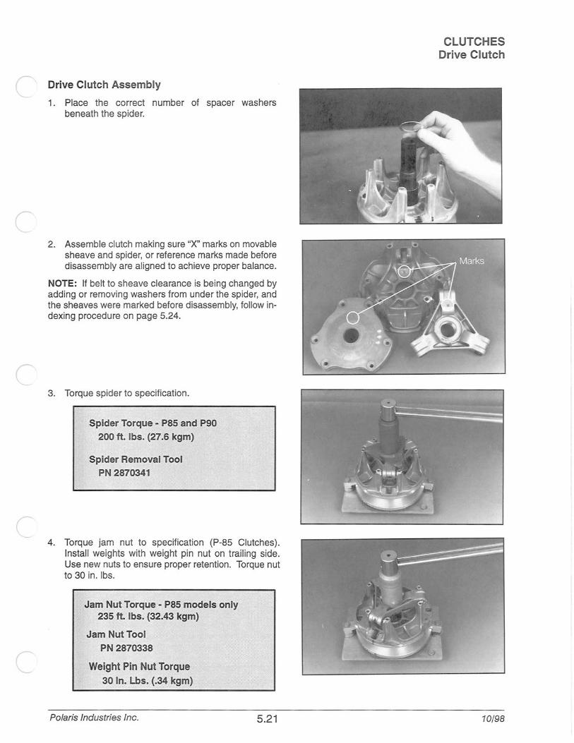
1. Place the correct number of spacer washers beneath the spider.
2. Assemble clutch making sure "X" marks on movable sheave and spider, or reference marks made before disassembly are aligned to achieve proper balance.
NOTE: If belt to sheave clearance is being changed by adding or removing washers from under the spider, and the sheaves were marked before disassembly, follow indexing procedure on page 5.24.
3. Torque spider to specification.
Spider Torque - P85 and P90 200ft. lbs. (27.6 kgm)
Spider Removal Tool PN 2870341
4. Torque jam nut to specification (P-85 Clutches). Install weights with weight pin nut on trailing side. Use new nuts to ensure proper retention. Torque nut to 30 in. lbs.
Jam Nut Torque - P85 models only 235 ft. lbs. (32.43 kgm)
Jam Nut Tool PN 2870338
Weight Pin Nut Torque 30 ln. Lbs. (.34 kgm)
Polaris Industries Inc.
..
5.21
CLUTCHES Drive Clutch
10/98

CLUTCHES Drive Clutch
Assembly, Cont. 5. Install spring and cover. Torque cover bolts evenly to
specification.
CAUTION: Carefully align bushing with shaft during installation of cover to prevent bushing damage. Maintain alignment by tightening cover bolts evenly and carefully.
Spider Cover Bolt Torque -
90 in. lbs. (1.03 kgm)
Installation
1. Slight galling or scoring of the bore taper can usually be corrected using a tapered reamer. Place reamer in a vise and lubricate with cutting oil. Clean taper by manually rotating clutch clockwise.
Tapered Reamer PN 2870576
2. Check crankshaft taper for gall ing or scoring. If necessary clean taper evenly with 200 grit emery cloth.
3. Both clutch taper and crankshaft taper should be clean and ~.
NOTE: Do not use harsh cleaners which may cause clutch taper to corrode during use. This will cause difficulty when removing clutch in future. Clean clutch taper with lacquer thinner or isopropyl alcohol.
10/98 5.22 Polaris Industries Inc.

I
Installation, Cont.
4. Slide clutch fully onto crankshaft taper.
5. Install retaining bolt with any spacers, washers or 0-rings. See appropriate parts manual for type and placement of retaining bolt components.
6. Torque retaining bolt to specifications. Hold clutch with strap wrench.
Drive Clutch Bolt Torque (Large ID Shaft)(3/4'1 40 - 45 ft. lbs (5.52 - 6.21 kgm)
Drive Clutch Bolt Torque (SmaiiiD Shaft)-; (14mm /7/16'1 50ft lbs. (6.9 kgm)
NOTE: Re-torque clutch to specification after first period of operation (such as a test ride) .
Polaris Industries Inc. 5.23
CLUTCHES Drive Clutch
10/98

CLUTCHES Drive Clutch
Spider Indexing
NOTE: Spider indexing affects clutch balance and belt to sheave clearance. Read procedures careful ly before proceeding.
1. Before disassembling drive clutch, mark spider, cover, moveable sheave, and stationary sheave in line with a permanent marker as shown.
2. Disassemble drive clutch as described on page 5.16. Take care to note the amount and thickness of the shim washers under the spider.
3. Add or remove spider washers as required to achieve desired belt to sheave clearance.
• For example: It belt to sheave clearance is .020" too large, removing one .020" shim will position the movable sheave closer to the fixed sheave reducing belt to sheave clearance by .020".
NOTE: The following washers are available tor tine tuning :
Washers: PN 521 0754 .050" PN 521 0753 .032" PN 5210752 .020"
4. Install spider washer(s) and spider aligning Xs. Notice as the spider seat location is changed, the sheave marks made before disassembly no longer align. There are two ways to bring the sheave marks into alignment.
• Vary the amount and thickness of spacer washers (Washer thickness may vary slightly}.
• Re-index marked spider leg to another tower. This can be done because spider has little effect on overall clutch balance.
Re-indexing the spider 1/3 turn clockwise, or 1 leg, wil l allow the realignment of the moveable and stationary sheaves as previously marked. For example:
• .020" or .032" washer removed - re-index spider clockwise 1/3 turn
• .050" or .064" washer removed - re-index spider clockwise 1/3 turn
• Two .050" or .064" washers removed -re-index clockwise 2/3 turn
NOTE: Alignment marks should be within 1" (25 mm) after final assembly and torquing.
10/98 5.24
--
Polaris Industries Inc.

( Driven Clutch Removal
(
r
(
(_
1. Remove driven clutch retaining bolt.
2. Slide driven clutch off jackshaft. It may be necessary to use a puller on some driven clutches. P-85 clutches (externally adjustable) can be removed using a 3-point flywheel or steering wheel puller and the 1/4-20 adjustment bolt holes. Use a suitable spacer on the end of the jacks haft.
P-90 Driven Clutch Puller
PN 2871056
3. Inspect jackshaft keyway (splines I P-90s) for wear or damage.
NOTE: Notice the number and thickness of shim washers between driven clutch and jackshaft bearing. These must be replaced to maintain proper offset/alignment.
Polaris Industries Inc. 5.25
CLUTCHES Driven Clutch
10/98

CLUTCHES Driven Clutch
Disassembly
1. Place clutch on bench.
CAUTION: Wear eye protection during disassembly and assembly of driven clutch.
2. Hold fixed sheave and turn movable sheave 1/4 turn. Hold movable in place tap helix down with a soft faced hammer. Remove snap ring and washer. NOTE: On models equipped with snap ring retainers as shown below, retainer may stay on back of snap ring when clutch is removed. Pry lightly to remove retainer and gain access to snap ring. (Refer to illustration below.)
If retainer stays with clutch, p evenly to remove (P-90)
Snap Ring
Retainer
3. Allow sheaves to return and force the helix out. Before removing helix, note driven clutch spring position. Remove helix.
4. Inspect helix ramps and movable buttons and for wear or damage. P-90 driven clutch ramp buttons are secured by Torx™ screws. P-85 buttons can be removed by applying heat to the button housing or drill button with an 1 /8" drill bit. The ramp buttons should be replaced when worn . See Maintenance section for inspection intervals.
10/98 5.26
J
J
Polaris Industries Inc.

(
c
Disassembly, Cont.
5. Remove driven clutch spring. Both spring tabs should line up. If not spring is fatigued and should be replaced.
6. Slide moveable sheave off and inspect sheave surfaces for wear or grooving. Note size and number of shim washers between sheaves.
7. Note condition of moveable sheave bushing. Install helix into bushing. It should slide freely without binding. See page 5.43 for bushing replacement.
8. Pol ish helix with a fine emery cloth to remove any sharp edges or build up which may cause sticking.
Polaris Industries Inc. 5.27
Tabs Aligned
CLUTCHES Driven Clutch
10/98

CLUTCHES Driven Clutch
Assembly
1. Install appropriate washer(s) on fixed shaft.
Optional Thin Adjustment Washer (P-85)
.048"- PN 7555899
2. Sl ide moveable sheave on fixed shaft .
3. Install driven clutch spring. Be sure spring tab is seated in hole in moveable sheave. Refer to specifications in front of this section for driven spring setting.
• P-85 driven clutches have 1 spring locating hole in the movable sheave and 4 holes in the helix.
• P-90 driven clutches have 2 spring locating holes in the movable sheave, and 3 in the helix
NOTE: The driven clutch helix/moveable assembly has several different spring locations which affect clutch shifting and RPMs. Tighter spring tension will raise engine RPMs during clutch upshift and allow quicker downshift when pulling or negotiating a hill. The lighter tension positions will tend to have a slower downshift and a harder up-shift. P-90
Moveable Example: Helix Sheave
Spring/ Position
B - 1 B - 2 A - 1 B - 3 A - 2
Spring Tension
A - 3 Soft P-90 production settings are usually 82 P-85 production settings are usually #2
4. Align inner keyway (P-85) or boss spline (P-90) between the helix and movable sheave. With the spring in place, slide helix onto shaft .5" (12mm).
10/98 5.28 Polaris Industries Inc.

r
Assembly, Cont.
Helix Angles and Effects
CLUTCHES Driven Clutch
The driven clutch helix was selected for overall performance in relation to the other driven system components. In fine tuning situations requiring a slight adjustment of engine operating RPM or improved backshift, we recommend trying a helix change before changing other components.
Polaris has several helix angles available for the P-85 and P-90 driven clutch. Refer to the chart below for specific angle effects and identification .
Helix Ramps* Description PN 34 5130896 34M* 5130751
36 5130895
36M* 5130717
38 5130723 40 5130724
42 5130725
44 5130726 40-36* 5130898 R1* 5131287
R2* 5131288 R3* 5131289 R4* 5131290 R5* 5131291 R6* 5131292 R7* 5131293 R8* 5131294 R9* 5131295 R10* 5131 296 R11* 5131 297 R32* 5131623 R12* 5131298 T-1 * 5131013 36.5 5130383 40-38-36 5131161
38-36 5131162 38-36-34 51311 63 34 5131164
Degrees
34 34
36 36 38 40
42 44 40-36 40-32 42-32 45-32 50-32 40-34 42-34 45-34 50-34 40-36
42-36 45-36 50-34 50-36 42-36-34
36.5 40-38-36
38-36 38-36-34
34
Type P85 P85 P85
P85 P85 P85
P85 P85 P85 P85 P85 P85 P85 P85 P85 P85 P85 P85 P85 P85 P85 P85 P-85
P90 P90
P90 P90 P90
The helix spring should always be adjusted within its limits before a helix change is performed. The normal rate of change between helix angle steps is 250 RPM under full throttle. This is approximately the same result as in going from the No. 1 to No. 4 spring position (P-85).
NOTE: Increasing spring tension increases engine RPM. RPM changes may not be evident if other drive or driven clutch components are substandard.
* NOTE: All R-Series, Mod(M), T1, and 40-36 helix ramps are cut 0.060" deeper in the snap ring pocket. These are made so the driven clutch can open far enough for full shift out with wide 1 7/16" belts (standard on Storm and 600/700 twins) .
If these helix ramps are used with narrow belts, 2 (two) additional (for a total of three) .030" /.8 mm washers (PN 7556804) should be installed under the snap ring to prevent the belt from touching the inner hub at full shift which can cause belt failure.
Wide belt models (Storm and 600&700 twins) use only the existing washer under the snap ring .
5. Hold fixed sheave and turn movable sheave 1/4 turn counterclockwise.
6. Force helix down into place, exposing snap ring groove.
Polaris Industries Inc. 5.29 10/98

CLUTCHES Driven Clutch
Assembly, Cont.
7. Install retainer (where applicable on P-90) spacer washer(s), and snap ring . Snap ring should be installed with flat (machined) side up or toward jackshaft bearing. NOTE: On models equipped with snap ring retainers as shown below, retainer may stay on back of snap ring when clutch is removed. Pry lightly to remove retainer and gain access to snap ring. (Refer to illustration below.)
Snap Ring Retainer
8. Allow sheaves to close. Test clutch by pre-loading movable sheave 1/4 turn counterclockwise and releasing. Sheave should open and close smoothly with a positive stop. Some helix ramps have more than one washer beneath the snap ring . Refer to page 6.37 for more information.
10/98 5.30
Preload 1/4turn
GtD NOTE: Always install snap ring with chamfer towards helix (sharp edge outward)
Polaris Industries Inc.

Installation
1. Install proper number of spacer washers on jackshaft between clutch and jackshaft bearing. Inspect Jackshaft Bearing Excessive vibration or abnormal drive belt wear can be caused by a worn bearing or jackshaft on the driven clutch side. To inspect bearing fit, watch the bearing area closely as you try to force the jackshaft up and down. If movement is detected, disassemble to determine which parts are worn. Replace the jackshaft if the new bearing is loose on the shaft. The bearing should be greased at 1000 mile (1600 km) intervals and before storage.
NOTE: Spacer washers between driven clutch and jackshaft bearing set the offset. Refer to adjustment procedure on page 5.36 to adjust offset between the drive and driven clutch.
2. Lightly grease jackshaft keyway or spline. With square key in place (P-85s) slide clutch onto jackshaft.
3. Install spacer, bolt and washer to hold driven clutch in place.
Driven Clutch Retaining Bolt Torque-
15 ft. lbs. (2.08 kg-m)
4. P-85 and P-90 driven clutches should float from side to side (.040-.080" (1 -2 mm)). Without a slight free float, jackshaft bearings could be side loaded, causing premature bearing failure. NOTE: Some models with P-90 clutches use a snap ring retainer cup to captivate the snap ring . On these models end float shou ld be adjusted between .000 and .01 0" (.000-.254 mm) Torque bolt to specification.
Driven Clutch Torque/Float .
, P·85/ P-90 • .040·.080" {1·2 mm) P-90 with retainer .000-.010" (.OOG-.254 mm)
Polaris Industries Inc. 5.31
CLUTCHES Driven Clutch
10/98

CLUTCHES Drive Belt
Drive Belt
Part No. Belt Width* (Projected)
3211042 1.375" (34.93mm)
3211045 1.375" (34.93mm)
3211058 1.250" (31 .75mm)
3211059 1.250" (31 .75mm)
3211061 1.375" (34.93mm)
3211065 1.438" (36.53mm)
3211066 1.375" (34.93mm)
3211067 1.375" (34.93mm)
3211070 1.375" (34.93mm)
3211073 1.438" (36.52mm)
3211074 1.438" (36.52mm)
3211075 1.438" (36.52mm)
Side Angle
Overall*
32°
32°
28°
28°
32°
28°
28°
28°
28°
28°
28°
28°
Center Outer Notes to Circum-
Center* ference* +.100" -.000" 12.00" 47.250" Common production belt for P-85 systems
12.00" 47.125" Close tolerance version of 3211 042
11 .00" 43.313" Indy Lite belt (P-90)
12.00" 45.125" Longer Indy Sport Belt (P-90)
12.00" 47.188" CVT version of 3211045
12.50" 48.375" CVT Double Cog Storm belt
12.00" 47.250" Double cog - CVT - thicker than 3211070. Pro-duction on higher horsepower snowmobiles.
12.00" 47.250" Double cog-Good for short runs on higher horsepower engines (Drag Racers) - Good for lower horsepower trail riding
12.00" 47.250" Common production belt for late model P-85 systems 1997 -current.
12.50" 48.375" Double cog- Good for short runs on higher horsepower engines (Drag Racers) -Good for lower horsepower trail riding
12.00" 47.625" Double cog-Good for short runs on higher horsepower engines (Drag Racers)- Good for lower horsepower trail riding
12.00" 47.625" Double cog - CVT
*± Belt dimensions given are nominal dimensions. There is a± variance for all critical dimensions. Clutch set-up must be inspected when a new belt is installed and, If necessary, clutch set-up must be adjusted.
The drive belt is an important component of the converter system. In order to achieve maximum efficiency from the converter, drive belt tension (deflection), clutch offset, and alignment must be adjusted properly.
General Belt Selection Guidelines
NOTE: Refer to appropriate parts manual for proper belt. Production belt is recommended unless tuning for a specific application.
CVT • Increased service life for high horsepower and extended high speed running • Need 1-2 grams heavier drive clutch weight • Good for prolonged high speed running. • Good for aggressive riders
Standard Compound
• More aggressive at low speeds • Reduced heat and drive clutch sheave wear • Used for short, higher horsepower runs (Drag Racing) • Good trail belt for lower horsepower engines.
10/98 5.32 Polaris Industries Inc.

t Drive Belt Inspection
1. Measure belt width and replace if worn severely. Generally, belt should be replaced if clutches can no longer be adjusted to provide proper belt deflection.
• The top edges have been trimmed on some drive belts. It will be necessary to project the side profiles and measure from corner to corner.
• Place a straight edge on each side of the drive belt.
• Place another straight edge on top of belt.
• Measure the distance where the side straight edges intersect the top, as shown in the illustration at right.
2. Inspect belt for loose cords, missing cogs, cracks, abrasions, thin spots, or excessive wear. Replace if necessary.
3. Inspect belt for hour glassing (extreme ci rcular wear in at least one spot and on both sides of the belt). Hour glassing occurs when the drive train does not move and the drive clutch engages the belt.
Belt Wear I Burn Diagnosis
CLUTCHES Drive Belt
~rojected Bel~ I Width I
Belt Wear I Burn Diagnosis Possible Cause Of Wear Or Burning Solution Driving at or about engagement RPM for extended periods in all Drive at higher RPM if possible . Gear the machine down. Make types of conditions sure belt deflection is at 1.25" to achieve optimum starting ratio
Cold weather startups Be patient. Warm up engine at least 5 minutes or until it readily responds to throttle input. For the quickest most efficient driveaway in extreme cold weather, take drive belt off machine and bring it in to a warm environment. Break skis and track loose from the snow. Engage throttle aggressively for short durations for initial cold drive-away
Towing another machine at or about engagement RPM When possible, do not go in deep snow when towing another rna-chine . Use fast, effective throttle to engage the clutch . Not all rna-chines are intended for pulling heavy loads or other machines.
Spinning track while vehicle is stuck (high RPM, low vehicle speed, Lower the gear ratio. Remove windage plates from driven clutch. If high ambient temp. Example: 8000 RPM, 10mph vehicle speed, 60 possible, move to better snow conditions and reduce RPM . Avoid mph indicated on speedometer. riding in very high ambient temperatures.
Ice and snow piled up between track and tunnel overnight or after Break loose snow and ice under tunnel. Allow longer than normal stopping for a long period of time (enough to re-freeze the snow) . warmup. Allow belt to warm sufficiently and increase grip ability on
clutch sheaves. Use fast, effective throttle when engaging clutch.
Poor running engine Maintain good state of tune including throttle and choke synchro-
(Bog, Miss, Backfire, etc.) nization. Check for fouled spark plug(s). Check for foreign material in carbs. Make sure no water or ice in fuel tank, lines, or carbure-tors.
Loading machine on trailer Use caution when loading machine. Carbide skags may gouge into trailer and prevent drive train from spinning freely. Use enough speed to drive completely onto trai ler. If machine cannot be driven completely onto trailer, it may need to be pulled or pushed to avoid belt wear I burning.
Clutch malfunction Check for correct clutch components.
Slow, easy belt engagement - easing on the throttle Use fast, effective throttle to engage the clutch.
Polaris Industries Inc. 5.33 10/98

CLUTCHES Drive Belt
Belt Deflection
Too much belt deflection - If the belt is too long or the center distance too short, the initial starting ratio will be too high, resu lting in performance loss. This is due to the belt rising too high in the drive clutch sheaves upon engagement.
Not enough belt deflection (belt too tight) - If the drive belt is too short or the center distance too long, the ratio will again be incorrect. In addition, the machine may creep when the engine idles, causing damage to the internal face of the drive belt.
10/98 5.34
Belt too high on initial engagement
Polaris Industries Inc.

(' Measuring Belt Deflection
CLUTCHES Drive Belt
IMPORTANT NOTE: Do not apply excessive pressure to force belt into driven sheaves. This will result in an improper measurement. If belt deflection cannot be adjusted within specification using methods below, inspect center distance and compare to specifications beginning on page 6.3.
1. Measure belt deflection with both clutches at rest and in their full neutral position.
2. Place a straight edge on the belt and apply downward pressure while measuring at the point shown.
Belt Deflection -
1 1/4" (3.2 em)
Adjusting Belt Deflection (P-90)
1 . Belt deflection on P-90 clutches is controlled by adding or removing shim washers from between the driven clutch sheaves. To change belt deflection, disassemble clutch as outlined on page 5.26.
2. Adjust shim stack between clutches to achieve desired belt deflection. At least 1 washer must remain between clutch sheave. • Remove washers to decrease belt deflection • Add washers to Increase belt deflection
3. Reassemble clutch as outlined on page 5.28.
Adjusting Belt Deflection (P-85)
Belt deflection can be adjusted without removing the clutch from the jackshaft.
1. Pull belt into driven clutch to slightly open sheaves.
2. Loosen three bolts on adjustment cam.
Used to adjust belt tension. One must always be installed.
3. Turn cam counterclockwise to reduce distance between sheaves. Do not rotate past #1 position.
Optional Thin Adjustment Washer (P-85)
.048" - PN 7555899 4. Torque bolts to specification.
Production washer is usually .075" thick with other .020 or .030 washers as required. May use optional, th inner (.048") washer PN 7555899 if required to obtain proper sheave width. Either the .075" or .048" washer must be installed in this location to provide support for the adjustment pins.
Polaris Industries Inc. 5.35 10/98

CLUTCHES Drive Belt
Clutch Offset Inspection NOTE: Proper offset aligns the fixed sheaves of both clutch assemblies. This allows the clutches to be aligned throughout the shift range.
1. Remove drive belt. Belt deflection adjustments affect offset. Set belt deflection first.
2. Install proper alignment tool, depending on type of clutch, as shown in Ill. 1.
3. Rear of driven clutch moveable sheave should just contact tool when clutch is pushed inward on jackshaft.
Clutch Alignment (Tools)-
P90- 21/32" Offset (PN 2870914) PBS - 5/B"Offset (PN 2870426)
P90 Electric Start-1.28"0ffset (straight edge) P85 Electric Start -1" Offset (straight edge)
Clutch Offset Adjustment
1. Determine direction driven clutch needs to be adjusted. (Refer to Clutch Offset Inspection procedure above) .
2. Remove driven clutch retaining bolt, and remove driven clutch .
3. Add or take out washers on jackshaft between the driven clutch and jackshaft bearing to achieve proper offset.
4. Most models require the driven clutch to float on the jackshaft. After adjusting offset, add or remove shim washers from the retaining bolt to provide a .030"-.060" (.75-1.5mm) of float on jackshaft. This will prevent side loads on the jackshaft bearing.
NOTE: On models with driven clutch snap ring retainer (Transport, Lite Touring, Sport Touring, etc.) the clutch is mounted firmly on the shaft without float.
NOTE: When checking electric start models, use a straight edge as shown in Ill. 2. If alignment is off, loosen the engine mounts and shift engine as required to obtain the proper offset and alignment.
Driven Clutch Bolt Torque -
12ft. lbs. (1.66 kgm)
10/98 5.36
Offset - Non-Electric Start Models
--.-A ::.. No gap at
21 /32" Offset
.:·:··:
: .. '..:_·,
Ill. 1
point "A" All models with P90 driven clutch 5/8" Offset All models with PBS driven clutch
NOTE: Up to .060" (1 .5mm) air gap allowed at point "B". Up to .125" is acceptable on new machines.
Offset Alignment Tool
Offset -Electric Start Models
Ill. 2
NOTE: Up to .060" (1 .5mm) air gap allowed at point "B". (.125" on new machines)
Polaris Industries Inc.

r
Clutch Alignment Inspection
CLUTCHES Drive Belt
NOTE: Drive clutches are purposely misaligned slightly forward to compensate for the engine shifting on it's mounts. Under load, the engine will pull back slightly so both clutches are in alignment.
1. After clutch offset has been verified, inspect alignment.
2. Install proper alignment tool, depending on type of clutch, as shown in Ill. 1 page 5.36.
3. There should be a .060" - .090" (1.5 - 2.25 mm) gap between front of driven clutch and tool, with the tool just touching at the rear. Up to .1 25" (3.1 mm) gap is acceptable in the front on new machines.
Clutch Alignment Adjustment
1 . Loosen all 4 engine mounting bolts.
2. Adjust engine torque stop until clutches are in proper alignment.
3. Tighten engine mounts securely.
4. Recheck both clutch offset and alignment.
5. Verify proper torque stop adjustment.
Torque Stop Adjustment
NOTE: There are two types of torque stops currently used. Refer to the illustrations below for adjustment of each type.
1. After aligning clutches, adjust torque stop by loosening lock nut and rotating stop to proper clearance as shown. Hold torque stop and tighten jam nut to 15-17 ft. lbs. (2.07-2.35 kg-m) .
ENGINE MOUNT TORQUE STOP
Adjust gap between stop and engine mount to .01 0"- .030" (.25 - . 75 mm)
± .005" (.13 mm) c.;--,, ..... '---, •' ". -~ro IW>\ ~·/
'"" .\<,,>.... ( \.(__ "" tm~1 \ I / i
~0 '~~/~ Engine Mount '-- :'J ~
Torque Stop\ •
~~)~~ 0
Lock ------'t _-vt/J Nut~~
N Ill J,
Polaris Industries Inc. 5.37
CRANKCASE TORQUE STOP
'"-.._.Q'
!J: )(1', / / ~\
\ Lock Nut
Adjust gap between stop and engine crankcase to .1 00" (2.5"mm) ± .01 0" (.25 mm)
10/98

CLUTCHES Drive Belt
Belt to Sheave Clearance Inspection
NOTE: The distance between the belt and the moveable sheave on the drive clutch is very important. This distance controls the starting ratio (lowest starting ratio is most preferable) and the position of the clutch weight to engine RPM. The distance between the belt and moveable sheave should be as close to .020" (.5 mm) as possible without creating a drag on the belt, when positioned around the hub at the bottom of the sheaves.
1. Force belt to one side of drive clutch. NOTE: Measure total belt to sheave clearance with a new belt.
• 2. Install feeler gage between other sheave and belt.
Belt to Sheave Clearance -
.020" ±.015"(.5 mm±.4mm)
Belt to Sheave Clearance Adjustment
Belt to sheave clearance can be adjusted in two ways.
1. Try several new belts to achieve proper clearance.
2. Can add or remove shims from under the spider to increase or decrease belt to sheave clearance. See Spider indexing on page 5.24.
NOTE: Spider indexing affects clutch balance and belt to sheave clearance. Read procedures carefu lly before proceeding.
NOTE: Belts with various widths will also affect belt deflection since they will fit differently in the driven clutch. Deflection should be checked per procedure on page 5.35.
10/98 5.38 Polaris Industries Inc.

Kit PN 2871 025
Item Oty. Part Description
1 P-85 Drive Clutch Moveable Bushing
Removal and Installation Tool
2 P-90 Drive Clutch and Driven Clutch
Bushing Installation Tool
3 Drive Clutch Cover Bushing Removal and Installation Tool (for all drive clutches)
4 P-85 Driven Clutch DU Split Bushing
Installation Tool
5 P-90 Driven Clutch Bushing Removal Tool
6 P-85 Driven Moveable Sheave Removal Tool
7 1 P-85 Driven Moveable Sheave
Removal Bridge
8 1 Main Puller Adapter
9 Adapter Reducer
10 Number Two Puller Adapter
11 Instruction You will need to supply:
Piston pin puller (PN 2870386) Bench vise Soft face hammer (for P-85 Driven Moveable) Small scribe or pick (for Cover Bushing Removal) Hand held propane torch (for P-90 Driven) Loctite RC 860 Retaining Compound (2870584)
P-85 Drive Clutch Cover Bushing Removal
1. Disassemble clutch as outlined in this section.
2. Inspect or measure bushing and replace if worn beyon1 service limit. Note: Bushing must be installed in covel There are two types of bushings used. Refer to th1 following specifications.
Cover Bushing Inspection: Garmax™ Style (Installed-Dimension) Nominal Bearing Bore: 1.125" (28.57mm) Service Limit: 1.140" (28.95mm)
Cover Bushing Inspection:
Teflon/Bronze Style Service Limit: Replace cover bushing if more bronze than Teflon™ is visible. Nominal Bearing Bore: 1.125" (28.57mm) Ser\tice Limit: · · 1:132" · (28:7smm) ' (Measure When Bushing is Installed) ··
Polaris Industries Inc. 5.39
CLUTCHES Clutch Bushing Replacement P-85
Part No.
5020627
5020628
5020629
5020630
5020631
5130862
5222768
5020632
5010279
5020633
9912260
10/98

CLUTCHES Clutch Bushing Replacement P-85
P-85 Drive Clutch Cover Bushing Removal Cont.
3. On models equipped with snap ring, remove round wire snap ring from inside of clutch cover using a small scribe or pick and set aside.
4. Install main adapter (Item 8) on puller.
5. From outside of clutch cover, insert removal tool (Item 3) into cover bushing.
6. With inside of cover toward vise, slide cover onto puller.
7. Install nut onto puller rod and hand tighten. Turn puller barrel to increase tension as needed.
8. Turn clutch cover counterclockwise on puller rod until bushing is removed.
9. Remove nut from puller rod and set aside.
1 0. Remove bushing and bushing removal tool from puller. Discard bushing.
P-85 Drive Clutch Cover Bushing Installation
1. On Garmax™ style bushings (PN 3576516) apply Loctite 680 retaining compound (PN 2870584) to the outer surface of the bushing. Retaining compound is not required on bronze I Teflon™ type bushings (PN 357651 0) . Do not lubricate bushings, or premature wear will result.
2. Working from inside of cover, insert bushing and bushing installation tool into center of clutch cover.
3. With main adapter on puller, insert cover onto pu ller rod, placing outside of cover toward vise.
4. Install nut on rod and hand tighten. Turn puller barrel to apply more tension if needed.
5. Turn clutch cover counterclockwise on puller rod until bushing is seated.
6. Remove nut from puller rod and take installation tool and clutch cover off rod.
7. Squeezing ends of snap ring, gently fit ring into clutch cover.
10/98 5.40 Polaris Industries Inc.

P-85 Drive Clutch Movable Sheave Bushing Removal
1. Inspect bushing and replace if excessively worn.
2. Install handle end of piston pin puller (PN 2870386) securely into bench vise and lightly grease puller threads.
3. Remove nut from puller rod and set aside.
4. Install main adapter (Item 8) onto puller. See Ill. 1.
5. Working from inside of moveable sheave, insert removal tool (Item 1) into center of sheave. With towers pointing away from vise, sl ide sheave onto puller rod .
6. Install nut removed in step 2 onto end of puller rod and hand tighten. Turn puller barrel to increase tension on sheave if needed.
7. Turn sheave counterclockwise on puller rod until it comes free.
8. Remove nut from puller rod and set aside.
9. Pull bushing removal tool and adapter from puller rod. Remove bushing from tool and discard.
10. Remove retaining ring from inside adapter and set aside.
Polaris Industries Inc. 5.41
Ill. 1
CLUTCHES Clutch Bushing Replacement P-85
Piston Pin Puller
Main Adaptor
10/98

CLUTCHES Clutch Bushing Replacement P-85
P-85 Drive Clutch Movable Sheave Bushing Installation
1. Place main adapter (Item 8) on puller.
2. Push new bushing into center of sheave by hand.
3. Insert installation tool (Item 1) into center of sheave and with towers pointing toward vise, slide sheave onto puller rod.
4. Install nut on puller rod and hand tighten. Turn barrel to apply additional tension if needed.
5. Turn sheave counterclockwise until bushing is seated.
6. Remove nut from puller rod and set aside.
7. Remove sheave from puller.
8. Remove installation tool.
9. Insert retaining ring removed in step 9 and installation tool into center of sheave.
10. With towers pointing toward vise, install sheave onto puller rod .
11. Install nut on puller rod and hand tighten. Turn barrel to apply additional tension if needed.
12. Turn sheave counterclockwise until ring is seated.
13. Remove nut from puller rod and set aside.
14. Remove sheave from puller.
15. Remove installation tool. Do not lubricate bushings, or premature wear will result.
10/98 5.42 Polaris Industries Inc.
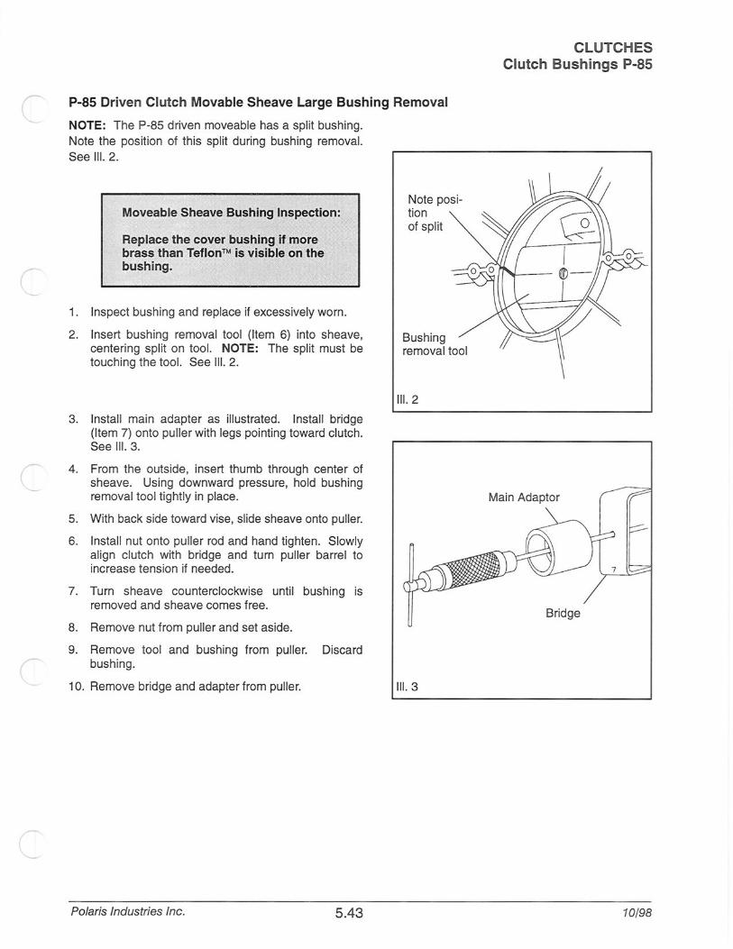
P-85 Driven Clutch Movable Sheave Large Bushing Removal
NOTE: The P-85 driven moveable has a split bushing. Note the position of this split during bushing removal. See Ill. 2.
Moveable Sheave Bushing Inspection: ix· ,/~_
Replace the cov.er bushil'lg if m()re brass than Teflon™ is visible on the· · bushing.
1. Inspect bushing and replace if excessively worn.
2. Insert bushing removal tool (Item 6) into sheave, centering split on tool. NOTE: The spl it must be touching the tool. See Ill. 2.
3. Install main adapter as illustrated. Install bridge (Item 7) onto puller with legs pointing toward clutch . See Ill. 3.
4. From the outside, insert thumb through center of sheave. Using downward pressure, hold bushing removal tool tightly in place.
5. With back side toward vise, slide sheave onto puller.
6. Install nut onto puller rod and hand tighten. Slowly align clutch with bridge and turn puller barrel to increase tension if needed.
7. Turn sheave counterclockwise until bushing is removed and sheave comes free.
8. Remove nut from puller and set aside.
9. Remove tool and bushing from puller. Discard bushing.
Note position of spl it
Bushing removal tool
Ill. 2
10. Remove bridge and adapter from puller. Ill. 3
Polaris Industries Inc. 5.43
CLUTCHES Clutch Bushings P-85
Main Adaptor
Bridge
10/98

CLUTCHES Clutch Bushings P-85
P-85 Driven Clutch Movable Sheave Large Bushing Installation
NOTE: The P-85 driven moveable has a split bushing. The bushing is held in place after installation by screws.
11. Insert bushing (PN 3569803) into clutch and tap lightly with a soft face hammer.
12. Install adapter number two (Item 1 0) onto puller. See Ill. 5.
13. Sl ide clutch sheave onto puller with back side away from vise.
14. Turn puller barrel until rod extends past back side of sheave.
15. Insert large installation tool for DU bushing (Item 4) onto rod.
16. Install nut onto puller rod and hand tighten. Turn puller barrel to increase tension as needed.
17. Turn clutch sheave counterclockwise until bushing is seated.
18. Remove nut from puller rod and set aside.
19. Remove installation tool and slide clutch sheave
Ill. 4
from puller. Ill. 5
Adapter Number Two
~------------------------------~ NOTE: The screws hold the bushing in place.
10/98 5.44 Polaris Industries Inc.

Polaris Kit PN 2871226
Item ~ 2
3
5
8
9 10
Part Description
P-90 Drive Clutch and Driven Clutch
Bushing Installation Tool
Drive Clutch Cover Bushing Removal and
Installation Tool (for all drive clutches)
P-90 Driven Clutch Bushing Removal Tool
Main Puller Adapter
Adapter Reducer
Number Two Puller Adapter
P-90 Drive Clutch Moveable Sheave- Bushing Removal
Moveable Sheave Bushing Inspection:
Replace the cover bushing if more brass than Teflon™ is visible on the bushing.
1. Install handle end of piston pin puller securely into bench vise and lightly grease puller threads.
2. Remove nut from puller rod and set aside.
3. Install main adapter (Item 8) onto puller.
4. Insert adaptor #2 into bushing from belt side as shown. With towers pointing toward vise, slide sheave and bushing onto puller rod.
5. Install nut removed in step 2 onto end of puller rod and hand tighten. Turn puller barrel to increase tension on sheave if needed. Nut is left hand thread.
Polaris Industries Inc. 5.45
Part No.
5020628
5020629
5020631
5020632
5010279
5020633
CLUTCHES Clutch Bushing P-90
Main Adaptor
10/98

CLUTCHES Clutch Bushing P-90
6. Turn sheave and puller barrel together counterclockwise on puller rod until bushing is removed .
7. Remove nut from puller rod and set aside.
8. Pull bushing removal tool and adapter from puller rod. Remove bushing from tool and discard.
Drive Clutch Moveable Sheave - Bushing Installation
9. Place main adapter (Item 8) on puller.
10. Push bushing into center of sheave on tower side by hand.
Bushing PN 3576504
11 . Insert installation tool (Item 2) into center of sheave and with towers pointing away from vise, slide sheave onto puller rod.
12. Install nut on puller rod and hand tighten. Turn barrel to apply additional tension if needed.
13. Turn sheave and barrel together counterclockwise until bushing is seated.
14. Remove nut from puller rod and set aside.
15. Remove sheave from puller.
16. Remove installation tool.
10/98 5.46 Polaris Industries Inc.

P-90 Drive Clutch Cover - Bushing Removal 1. Install main adapter (Item 8) on puller.
2. From outside of clutch cover, insert removal tool (Item 3) into cover bushing.
3. With inside of cover toward vise, slide cover onto puller.
4. Install nut onto puller rod and hand tighten. Turn puller barrel to increase tension as needed.
5. Turn clutch cover counterc lockwise on puller rod until bushing is removed.
6. Remove nut from puller rod and set aside.
7. Remove bushing and bushing removal tool from puller. Discard bushing.
Polaris Industries Inc. 5.47
CLUTCHES Clutch Bushing P-90
Main Adaptor
10/98

CLUTCHES Clutch Bushing P-90
P-90 Drive Clutch Cover - Bushing Installation
8. On Garmax™ style bushings (PN 3576516) apply Loctite 680 retaining compound (PN 2870584) to the outer surface of the bushing. Retaining compound is not required on bronze I Teflon™ type bushings (PN 357651 0). Do not lubricate bushings, or premature wear will result. Working from inside of cover, insert bushing and bushing installation tool into center of clutch cover.
9. With main adapter on puller, insert cover onto puller rod, placing outside of cover toward vise.
10. Install nut on rod and hand tighten. Turn puller barrel to apply more tension if needed.
11. Turn clutch cover and barrel together counterclockwise on puller rod until bushing is seated.
12. Remove nut from puller rod and take installation tool and clutch cover off rod.
10/98 5.48
-
Polaris Industries Inc.

P-90 Driven Clutch Moveable Sheave -Bushing Removal
NOTE: Bushings are installed at the factory using Loctite™ 680. In order to remove the bushing it will be necessary to apply heat.
13. Install main adapter (Item 8) onto puller.
14. Insert adapter reducer (Item 9) onto puller, sliding it inside the main adapter ..
15. Remove ramp buttons from moveable sheave.
16. Using a hand held propane torch, apply heat directly on bushing until tiny smoke tailings appear.
CAUTION: I Clutch components will be hot! In order to avoid serious burns, wear some type of insulated gloves for the rest of the removal process.
Polaris Industries Inc. 5.49
CLUTCHES Clutch Bushing P-90
Main Adapter
\
Adapter Reducer
10/98

CLUTCHES Clutch Bushing P-90
17. Working from the top, install bushing removal tool (Item 5) into center of clutch sheave with smaller diameter toward bushing to be removed. See illustration at right.
18. Install sheave onto puller.
19. Install nut onto puller rod and tighten by hand. Turn puller barrel for further tension if needed.
20. Turn clutch sheave counterclockwise until bushing is removed. Repeat steps 17. - 20. for other bushing.
21. Remove nut from puller rod and set aside.
22. Remove adapters from puller.
23. Remove bushing and removal tool from adapters. Discard bushing.
10/98 5.50 Polaris Industries Inc.

..- P-90 Driven Clutch Moveable Sheave - Bushing Installation
24. Working from the top, insert adapter number ten onto puller. See illustration at right.
25. Start new bushing evenly in moveable sheave.
26. Install sheave onto puller with new bushing upward as shown. Install adaptor number two.
Polaris Industries Inc. 5.51
CLUTCHES Clutch Bushing P-90
Adapter Number Ten
10/98

CLUTCHES Clutch Bushing P-90
27. Install nut onto puller rod and hand tighten against installation tool.
28. Turn clutch sheave counterclockwise until bushing is seated.
29. Remove nut from puller rod and set aside.
30. Remove installation tool and clutch sheave from puller.
31 . Repeat installation procedure for other moveable bushing.
10/98 5.52 Polaris Industries Inc.

SYMPTOMS PROBABLE CAUSE
Harsh drive clutch engage- -Drive belt worn too narrow ment
-Excessive belt to sheave clearance with new belt (high performance version with-out detent shift weight)
Drive belt turn over -Wrong belt for appl ication
-Clutch alignment out of spec
-Engine mount broken or loose
-Driven clutch sheaves have excessive runout, are bent or damaged
Noise in drive system -Broken drive clutch components
-Excessive drive clutch button -tower clearance
-Bearing failure/ chaincase, jackshaft or front drive shaft
-Drive chain loose or worn, sprocket teeth broken
-Driven clutch bushing worn excessively or spring broken
-Drive chain adjustment too tight/too loose
-Drive belt surface flat spots
Over rev during initial accel- -Spider roller position remaining in detent eration or during heavy pulling at low ground speeds.
Engine bogs after engage- -Improper driven clutch setup ment.
-Worn belt
-Excessive belt deflection
-Improper offset/alignment
-Broken or misadjusted torque stop
-Broken motor mount
-Jackshaft bearing seizure
Polaris Industries Inc. 5.53
CLUTCHES Troubleshooting
REMEDY
-Replace
-Perform belt to sheave clear-ance adjustment with shim washers beneath spider
-Replace
-Adjust alignment offset
-Inspect, adjust or replace
-Measurement should be tak-en .25" in from outer circum-terence on sheave face. Max-imum allowable tolerance is .015" (.6 mm).
-Inspect/replace
-Install new buttons or shim out existing buttons
-Inspect/replace
-Inspect/adjust or replace
-Inspect/replace
-Inspect/replace
Inspect/adjust
Inspect/replace
-Add spider shim washers
-Add driven washers
-Reduce gear ratio (chaincase models)
-Replace
-Subtract driven clutch wash-ers
-Inspect/adjust
-Inspect/adjust/replace
-Inspect/replace
-Replace
10/98

CLUTCHES Clutch System Troubleshooting
SYMPTOMS PROBABLE CAUSE REMEDY
Engine RPM below specified a) Wrong or broken drive clutch spring a) Replace with recommended spring
operating range, although en- b) Drive clutch shift weight too heavy b) Install correct shift weight kit to
gine is properly tuned c) Driven clutch spring broken or installed match engine application
in wrong helix location c) Replace spring; refer to proper d) Drive belt too long installation location
e) Improper driven clutch setup d) Install new belt and/or adjust belt
tension
e) Install correct parts and/or adjust to
match engine application and ma
chine use
Erratic engine operating RPM Drive clutch binding or driven clutch -Disassemble drive clutch; inspect shift
during acceleration or load malfunction weights for wear and free operation
variations Clean clutches; install new belt
Converter sheaves greasy; belt slippage -Clean and polish stationary shaft hub;
reassemble clutch without spring to
determine problem area
-Replace ramp buttons
-Inspect moveable sheave for excessive
bushing clearance/replace
Engine RPM above specified a) Incorrect drive clutch spring (too high a) Install proper spring
operating range spring rate) b) Install proper shift weights
b) Drive clutch shift weights incorrect for c) Disassemble and clean clutch,
application (too light) inspecting shift weights and buttons. c) Drive clutch binding Reassemble without the spring to
d) Driven clutch binding determine probable cause.
e)Converter sheaves greasy; belt sl ippage d)-Disassemble, clean and inspect
f) Improper driven clutch setup driven clutch , noting worn sheave bushing and ramp buttons and helix
spring location e) Clean clutches; install new belt
f) Install correct parts and/or adjust to match engine application and ma
chine use
Burnt Belts I Premature Wear a) Wrong or broken drive clutch spring a) Replace with recommended spring
Also see Belt Wear I Burning b) Drive clutch shift weight too heavy b) Install correct shift weight kit to match
Diagnosis Chart on page 6.63 c) Driven clutch spring broken or installed engine application
in wrong helix location c) Replace spring; refer to proper
d) Drive belt too long installation location
e) Converter sheaves greasy; belt sl ip- d) Install new belt and/or adjust belt
page. tension
f) Improper driven clutch setup e) Clean clutches; install new belt
f) Install correct parts and/or adjust to
match engine application and rna chine use
10/98 5.54 Polaris Industries Inc.

r
r
CLUTCHES Belt Wear I Burn Diagnosis
Belt Wear I Burn Diagnosis
Possible Cause Of Wear Or Burning Solution
Driving at or about engagement RPM for extended Drive at higher RPM if possible. Gear the machine periods in all types of conditions down. Make sure belt deflection is at 1.25" to
achieve optimum starting ratio
Cold weather startups Be patient. Warm up engine at least 5 minutes or until it readily responds to throttle input. For the quickest most efficient driveaway in extreme cold weather, take drive belt off machine and bring it in to a warm environment. Break skis and track loose from the snow. Engage throttle aggressively for short durations for initial cold driveaway
Towing another machine at or about engagement When possible, do not go in deep snow when towing RPM another machine. Use fast, effective throttle to en-
gage the clutch. Not all machines are intended for pulling heavy loads or other machines.
Spinning track while vehicle is stuck (high RPM, low Lower the gear ratio. Remove windage plates from vehicle speed, high ambient temp. Example: 8000 driven clutch. If possible, move to better snow condi-RPM, 1Om ph vehicle speed, 60 mph indicated on tions and reduce RPM. Avoid riding in very high am-speedometer. bient temperatures .
Ice and snow piled up between track and tunnel Break loose snow and ice under tunnel. Allow longer overnight or after stopping for a long period of time than normal warmup. Allow belt to warm sufficiently (enough to re-freeze the snow). and increase grip abil ity on clutch sheaves. Use fast,
effective throttle when engaging clutch.
Poor running engine Maintain good state of tune including throttle and
(Bog, Miss, Backfire, etc.) choke synchronization. Check for fouled spark plug(s) . Check for foreign material in carbs. Make sure no water or ice in fuel tank, lines, or carbure-tors.
Loading machine on trailer Use caution when loading machine. Carbide skags may gouge into trailer and prevent drive train from spinning freely. Use enough speed to drive com-pletely onto trailer. If machine cannot be driven com-pletely onto trailer, it may need to be pulled or pushed to avoid belt wear I burning.
Clutch malfunction Check for correct clutch components.
Slow, easy belt engagement- easing on the throttle Use fast, effective throttle to engage the clutch.
Polaris Industries Inc. 5.55 10/98

J
)
J