Embed Size (px)
Citation preview

http://www.iaeme.com/IJMET/index.asp 529 [email protected]
International Journal of Mechanical Engineering and Technology (IJMET)
Volume 8, Issue 8, August 2017, pp. 529–541, Article ID: IJMET_08_08_059
Available online at http://www.iaeme.com/IJMET/issues.asp?JType=IJMET&VType=8&IType=8
ISSN Print: 0976-6340 and ISSN Online: 0976-6359
© IAEME Publication Scopus Indexed
DESIGN AND FABRICATION OF
SYNCHRONIZED CLUTCH FOR AUTOMATIC
SLIDING DOOR
D.L. Belgin Paul, M. Karthick, A. Sathesh Kumar
Assistant Professor, Department of Mechanical Engineering,
Vel Tech University, Avadi, Chennai, Tamilnadu, India
ABSTRACT
Clutches are device which are used to transmit power from the driver shaft to the
driven shaft. Synchronized clutch is used to transmit power with very low or negligible
power loss which is desirable in case of low power transmission and also it performs
the general function of clutch. Torque is not controlled in this type of clutch. The slip
is minimal or none. Solenoids are used to engage and disengage the clutch. Thus the
operation of clutch is automatic and does not require any manual intervention. This
clutch is electromechanical type and hence gaining the advantage of both. This
project presents the design of synchronized clutch and also a prototype is made to test
the function of clutch. “SOLIDWORKS” software is used to model the clutch and also
to ensure the feasibility of manufacturing and assembly (DFMA). This type of clutch is
used in low power transmission like automatic sliding door of Operation Theatres.
Key words: Clutch, Operating Room, Design Input, Conceptual Design, Synthesis of
Mechanism, Decision matrix, Embodiment Design, Product architecture, Configuration
Design, parametric Design, Design Output, Prototype.
Cite this Article: D.L. Belgin Paul, M. Karthick, A. Sathesh Kumar, Design and
Fabrication of Synchronized Clutch for Automatic Sliding Door, International Journal
of Mechanical Engineering and Technology, 8(8), 2017, pp. 529–541.
http://www.iaeme.com/IJMET/issues.asp?JType=IJMET&VType=8&IType=8
1. INTRODUCTION
A clutch is a mechanical device that engages and disengages the power, transmission,
especially from driving shaft to driven shaft. Clutches are used whenever the transmission of
power or motion must be controlled either in amount or over time (e.g., electric screwdrivers
limit how much torque is transmitted through use of a clutch; clutches control whether
automobiles transmit engine power to the wheels). In the simplest application, clutches
connect and disconnect two rotating shafts (drive shafts or line shafts). In these devices, one
shaft is typically attached to an engine or other power unit (the driving member) while the
other shaft (the driven member) provides output power for work.
Operation Room is an essential part of any hospital especially a multi-speciality hospital.
Increased construction of hospital and operation room has raised a demand for innovation in

D.L. Belgin Paul, M. Karthick, A. Sathesh Kumar
http://www.iaeme.com/IJMET/index.asp 530 [email protected]
medical products. Generally there would be Power Backups in Multi-Speciality hospitals but
there are cases where hospitals have minimum or no power backup or breakdown of power
backup and there is a minimum time for power generation through power backup device. At
these cases manual type of doors comes in handy as in hospital time is a critical aspect. But
most of hospitals uses automatic sliding door which is easier to use with power. Some
automatic sliding doors comes with a lever to be pulled while power failure. The installation
of lever, the ease of pull of lever, position of lever (whether inside operation room or outside
operation room or both) etc. are dependent on installation and manufacturer. Hence in case of
power failure the automatic sliding door should turn into a manual door and when power
comes back the manually operating door must turn back to automatic sliding door without any
human intervention
Synchronized Clutch is a non-friction type clutch and has pin on the driven side and slot
on the driver side. When the clutch engages the power is transmitted from slot to pin.
Engagement and disengagement of clutch is based on electromechanical solenoid and when
there is no power the clutch gets disengaged thus allowing manual operation. Material
Selection and introduction of solenoid makes the clutch different from the other types as this
clutch is cost effective and performs it function as usual. This clutch is introduced in
Operation theatre automatic sliding door. With power it engages driver and driven thus
making door automatic and with power failure it disengages thus making door manual.
2. DESIGN INPUT
2.1. Problem Definition
Door must work as automatic sliding door with power and in case of power failure door must
become manually operating door without any external human intervention. Once the power
comes it must turn back into automatic sliding door. The mechanism should be cost effective.
It should be compact and should have high efficiency as this is a low power transmission
2.1.1. Door Specification
Dimensions of Door: 7 feet X 6 feet = 2133.6 X 1828 = 2140 X 1830 mm2
Weight of the Door = 120 kg to 150 Kg
Travel Distance = 12 feet = 3657.6 mm = 3660mm
Maximum Speed = 2 feet/s = 0.6096 ms-1
These are the design inputs obtained from physical measurement of door and these
requirements are generally required by most of the hospitals.
2.1.2. Power Calculation
Velocity V is not a constant. It varies from 0 to 0.6096 m/s. So acceleration = dv/dt = ∆v/∆t =
0.6096/2 = 0.3048 (from kinematics, v = u + at). Therefore acceleration a = 0.3048 ms-2
Coefficient of friction between Aluminium and Nylon is assumed to be 0.04 (Once body
starts moving, coefficient of friction decreases)
Acceleration due to gravity = 9.81 ms-2

Design and Fabrication of Synchronized Clutch for Automatic Sliding Door
http://www.iaeme.com/IJMET/index.asp 531 [email protected]
Figure 1 Free Body Diagram
Minimum Force required to move the object Fmin = Friction force + Inertia Force
Fmin = µRn + ma
= {0.04 * (150*9.81)} + 150*0.3048
= 58.86 + 45.72
= 104.58 N
The Force that acts on the motor is 156.87 N when FOS of 1.2 is considered
Power = Force X Velocity = 76.50 W
Thus this scenario can be considered as Low Power Transmission approximated to 80 W.
Gear ratio of motor must be high enough so that the door must not be open by outsiders or
anyone manually when it is functioning as automatic sliding door
Since hospital zone is considered, the hospital door and all its related mechanism should
be considered as medical device of class 3 and hence the mechanism to be designed must
comply with ISO 13485
The next stage is to develop a mechanism which suits all above requirements.
SOLIDWORKS software is the design tool used in modelling the required mechanism and
prototype has to be done to review and verify the design output.
3. CONCEPTUAL DESIGN
Conceptual design is the first stage of product development process once the product design
specification (PDS) is confirmed. From the previous analysis (Design input) we concluded the
requirements of the product. Conceptual Design is the stage where the primary concept or the
outline is derived. Conceptual design is the process by which the design is initiated, carried to
the point of creating a number of possible solutions, and narrowed down to a single best
concept. From the number of possible solutions by using type synthesis and by evaluating
ideas with respect to criteria (decision matrix) a concept is selected. That will be the basic
idea of the mechanism which will be refined in embodiment and finalized in parametric
design phase. Once the concept is selected the product design specification is revisited and
refined if required (8)
.

D.L. Belgin Paul, M. Karthick, A. Sathesh Kumar
http://www.iaeme.com/IJMET/index.asp 532 [email protected]
3.1. Synthesis of Mechanism
Type synthesis is the process of selection of type of mechanism needed to accomplish a given
requirement (5)
. It is generally depend design factors like manufacturing process, material
availability, safety, reliability, space, and economics which are outside kinematics itself (6)
.
There are six different categories like
Lower Pairs
Wheels, including Gears, Clutches etc.
Cams and their forms
Screw mechanism
Intermittent-motion devices
Tension and compression parts with one way rigidity
Number Synthesis is the stage where degree of freedom is considered. The degree of
freedom for the required mechanism is 1 as there is one input from motor and one output
required which is a sliding motion. Degree of freedom in mechanics is defined as number of
output or independent movement in a mechanism
Dimensional Synthesis is as the name specifies it boils down to solving of synthesis
equation that expresses the desired motion in terms of the required unknown dimensions.
These unknowns include, among other things, the link lengths, relative locations of revolute
centres, and in particular for function generators, a zero or home configuration.
3.2. Decision Matrix
A decision matrix is a method of evaluating competing concepts by ranking the design criteria
with weighting factors and scoring the degree to which each design concept meets the
criterion. A 5 point scale (0-4) is used (8)
. Since we know the requirement we can tabulate a
table with Requirements (known) along rows and mechanism (unknown) along column. The
most important requirements will be the function, cost and size. Totally useless solution is
rated as 0 and excellent solution is rated as 4 (8)
.
Table 1 Decision Matrix
Lower Pair Wheels CAM Screw
Intermittent
Motion
Device
Tension and
Compression
Parts
FUNCTION 3 4 3 0 2 2
COST 4 4 1 3 2 4
SIZE 2 4 4 2 4 1
The scale rating is done based on field data of design engineer and manufacturer
From the table the best mechanism is Wheels (Clutches) which matches exactly with the
function requirement. Cost and size is also less when compared with other mechanism as seen
above in table. Requirements like low power transmission has to be considered while
considering clutches because clutches has power loss due to friction factor. Modern Single-
Plate and Multi-plate Clutches has clutch plates made of compound organic resin with copper
wire facing or a ceramic material. A typical Coefficient of friction used in friction disc surface
is 0.35 for organic and 0.25 for ceramic (11)
. Hence power loss will be higher. Thus we have to
use electromagnetic clutch which is costlier. Thus we use synchronized clutch which is an

Design and Fabrication of Synchronized Clutch for Automatic Sliding Door
http://www.iaeme.com/IJMET/index.asp 533 [email protected]
adaptive design (8)
. Synchronized Clutch is a pin and slot type clutch and transfers power
between driver and driven shaft with minimum or less power loss. The Embodiment design
will have the details of its configuration and parametric details like dimensions tolerance etc.
Detail design will have manufacturing drawings of the same. DFMA feedback will also be
attached as prototype results.
4. EMBODIMENT DESIGN
Structured development of the design concept occurs in this engineering design phase. It is the
place where flesh is placed on the skeleton of the design concept. It is in this design phase that
decisions are made on strength, material selection, size, shape, and spatial compatibility.
Beyond this design phase, major changes become very expensive. Embodiment design is
generally categorized into product architecture, configuration design and parametric design.
4.1. Product Architecture
Synchronized clutch has pin on the driven side and slot on the driver side. The power is
transmitted from slot to pin. Hence the slot pushes the pin rather than pin pushing the slot.
When the power shuts down the actuator pushes the clutch plate 1 away which makes the pin
move away from the slot thus disengaging the clutch. When power arrives the solenoid
contracts back due to electromagnetic field and the tension springs on sliding shaft (shaft 4)
will pull back the clutch plate to its original position thus engaging the slot and the pin and
hence engaging the clutch. Support plate which is on the driver side will also rotate along
with the driven shaft in-order to maintain the alignment of driver and driven side and also to
support the sliding shaft. Hence a bearing is used to make sure that the shaft doesn’t carry any
stress as the driver side does not have reverse direction of rotation due to worm gear
arrangement.
Figure 2 Exploited View
Figure 3 Engaged Position
D.L. Belgin Paul, M. Karthick, A. Sathesh Kumar
http://www.iaeme.com/IJMET/index.asp 534 [email protected]
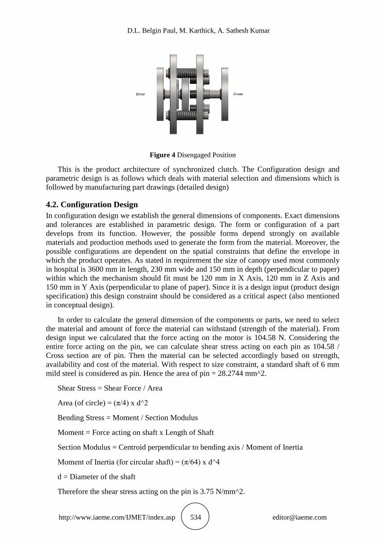
Figure 4 Disengaged Position
This is the product architecture of synchronized clutch. The Configuration design and
parametric design is as follows which deals with material selection and dimensions which is
followed by manufacturing part drawings (detailed design)
4.2. Configuration Design
In configuration design we establish the general dimensions of components. Exact dimensions
and tolerances are established in parametric design. The form or configuration of a part
develops from its function. However, the possible forms depend strongly on available
materials and production methods used to generate the form from the material. Moreover, the
possible configurations are dependent on the spatial constraints that define the envelope in
which the product operates. As stated in requirement the size of canopy used most commonly
in hospital is 3600 mm in length, 230 mm wide and 150 mm in depth (perpendicular to paper)
within which the mechanism should fit must be 120 mm in X Axis, 120 mm in Z Axis and
150 mm in Y Axis (perpendicular to plane of paper). Since it is a design input (product design
specification) this design constraint should be considered as a critical aspect (also mentioned
in conceptual design).
In order to calculate the general dimension of the components or parts, we need to select
the material and amount of force the material can withstand (strength of the material). From
design input we calculated that the force acting on the motor is 104.58 N. Considering the
entire force acting on the pin, we can calculate shear stress acting on each pin as 104.58 /
Cross section are of pin. Then the material can be selected accordingly based on strength,
availability and cost of the material. With respect to size constraint, a standard shaft of 6 mm
mild steel is considered as pin. Hence the area of pin = 28.2744 mm^2.
Shear Stress = Shear Force / Area
Area (of circle) = (π/4) x d^2
Bending Stress = Moment / Section Modulus
Moment = Force acting on shaft x Length of Shaft
Section Modulus = Centroid perpendicular to bending axis / Moment of Inertia
Moment of Inertia (for circular shaft) = (π/64) x d^4
d = Diameter of the shaft
Therefore the shear stress acting on the pin is 3.75 N/mm^2.

Design and Fabrication of Synchronized Clutch for Automatic Sliding Door
http://www.iaeme.com/IJMET/index.asp 535 [email protected]
Bending stress will be 148.62 N/mm^2.
Principal stress = (σx + σy) / 2 + Principal Shear Stress
Principal Shear Stress = √ {[(σx^2 – σy^2) / 2] + τxy^2}
σy = 0 for circular shaft as the shaft is uniaxial loaded
Principal Shear Stress = 104.72 N/mm^2
Principal Stress = 179.03 N/mm^2
Considering a Factor of safety of 1.2, Maximum Principal tensile stress acting on the shaft
is 214.836 N/mm^2 and Maximum Principal Shear stress is 125.664 N/mm^2
Stainless steel AISI 304 has a Yield Strength of 215 N/mm^2.
From theory of failures (1)
considering Von Mises theory for ductile materials, Von Mises
stress for uniaxial material is σ = √(σx^2 + 3τxy^2) = 148.66 N/mm^2
Thus the yield strength is greater than Von Mises stress with a factor of safety of 1.446.
Thus strength of material is greater than stress of material and hence Mild Steel BIS 513 can
be selected (12)
. When considering availability and cost of the material, Mild Steel BIS 513 is
readily available and economic. Since the selected material falls inside the requirement, this
material can be selected.
We have to note that critical area has been considered for stress calculation. And the case
we considered is when the entire force acts on single pin which has very less possibility as the
support plate keeps track of alignment of driver and driven shafts within tolerance limits.
Thus even with critical situation is considered the material selected is safe in operating zone.
Non critical areas are considered as Mild steel BIS 513 due to the reason of its higher
availability, cost effectiveness and easier to manufacture. Delrin 100 material is M4 tapped
and guided into the screw thus making it a 6 mm shaft in-order to reduce noise and vibration
during engagement of slot to the pin where Delrin acts as a damper absorbing some amount of
energy. Delrin 100 is also readily available, cost effective and easy to manufacture. Total size
is considered in such a way that the dimension of synchronized clutch falls inside the required
size as given in design input (canopy size). SOLIDWORKS software is used as a 3D CAD
tool for configuration design.
4.3. Parametric Design
In configuration design the emphasis was on starting with the product architecture and then
working out the best form for each component. Qualitative reasoning about physical
principles and manufacturing processes played a major role. In parametric design the
attributes of components identified in configuration design become the design variables for
parametric design. A design variable is an attribute of a part whose value is under the control
of the designer. This typically is a dimension or a tolerance, but it may be a material, heat
treatment, or surface finish applied to the part. This aspect of design is much more analytical
than conceptual or configuration design. The objective of parametric design is to set values
for the design variables that will produce the best possible design considering both
performance and cost.
First step of parametric design is to consider the solution evaluation parameters (SEP’s)
which should be traced back to product design requirement or design input. As noted in
conceptual design these SEP’s are Function, cost and size. As far as synchronized clutch is
D.L. Belgin Paul, M. Karthick, A. Sathesh Kumar
http://www.iaeme.com/IJMET/index.asp 536 [email protected]
considered, it Function and size has been within Design constraint. The total cost of
synchronized clutch is based on material and manufacturing cost and the cost should be less
than 80W Electromagnetic clutch which is more than 150 USD. As the general dimension has
been done in configuration design, the finalization of size, providing geometric tolerance, fits
and DFMA should be emphasized in parametric design.
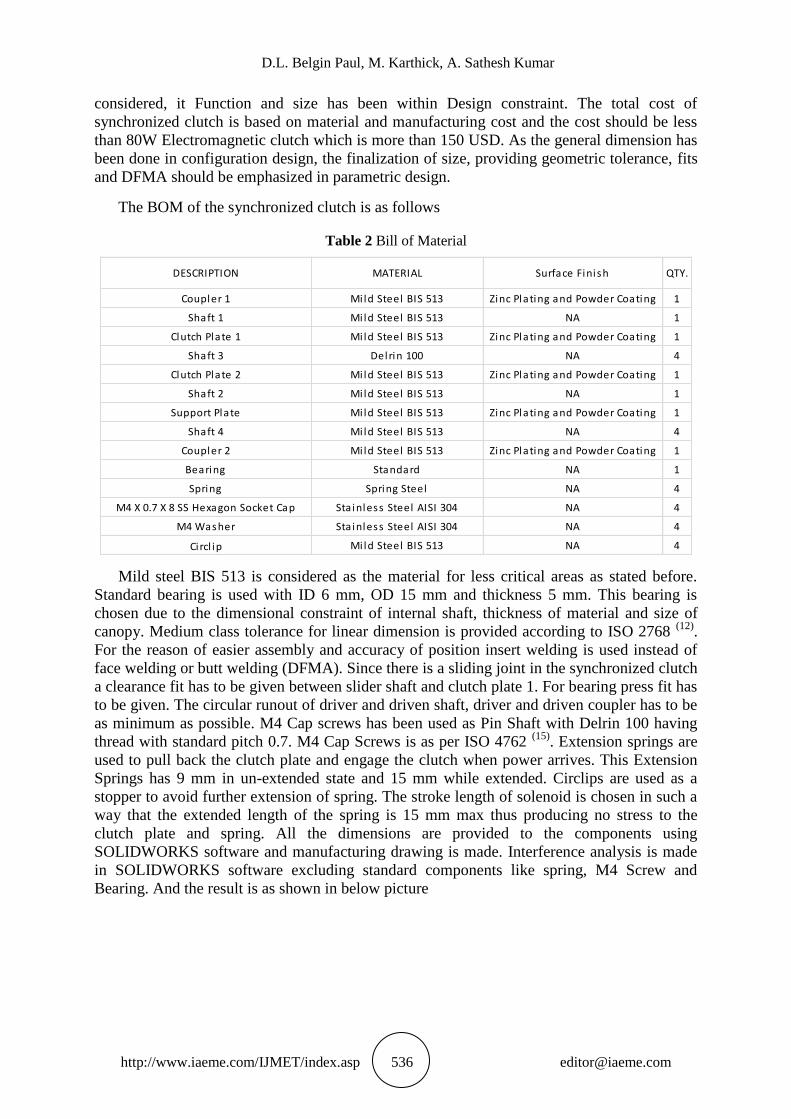
The BOM of the synchronized clutch is as follows
Table 2 Bill of Material
DESCRIPTION MATERIAL Surface Finish QTY.
Coupler 1 Mi ld Steel BIS 513 Zinc Plating and Powder Coating 1
Shaft 1 Mi ld Steel BIS 513 NA 1
Clutch Plate 1 Mi ld Steel BIS 513 Zinc Plating and Powder Coating 1
Shaft 3 Delrin 100 NA 4
Clutch Plate 2 Mi ld Steel BIS 513 Zinc Plating and Powder Coating 1
Shaft 2 Mi ld Steel BIS 513 NA 1
Support Plate Mi ld Steel BIS 513 Zinc Plating and Powder Coating 1
Shaft 4 Mi ld Steel BIS 513 NA 4
Coupler 2 Mi ld Steel BIS 513 Zinc Plating and Powder Coating 1
Bearing Standard NA 1
Spring Spring Steel NA 4
M4 X 0.7 X 8 SS Hexagon Socket Cap Stainless Steel AISI 304 NA 4
M4 Washer Stainless Steel AISI 304 NA 4
Circl ip Mi ld Steel BIS 513 NA 4
Mild steel BIS 513 is considered as the material for less critical areas as stated before.
Standard bearing is used with ID 6 mm, OD 15 mm and thickness 5 mm. This bearing is
chosen due to the dimensional constraint of internal shaft, thickness of material and size of
canopy. Medium class tolerance for linear dimension is provided according to ISO 2768 (12)
.
For the reason of easier assembly and accuracy of position insert welding is used instead of
face welding or butt welding (DFMA). Since there is a sliding joint in the synchronized clutch
a clearance fit has to be given between slider shaft and clutch plate 1. For bearing press fit has
to be given. The circular runout of driver and driven shaft, driver and driven coupler has to be
as minimum as possible. M4 Cap screws has been used as Pin Shaft with Delrin 100 having
thread with standard pitch 0.7. M4 Cap Screws is as per ISO 4762 (15)
. Extension springs are
used to pull back the clutch plate and engage the clutch when power arrives. This Extension
Springs has 9 mm in un-extended state and 15 mm while extended. Circlips are used as a
stopper to avoid further extension of spring. The stroke length of solenoid is chosen in such a
way that the extended length of the spring is 15 mm max thus producing no stress to the
clutch plate and spring. All the dimensions are provided to the components using
SOLIDWORKS software and manufacturing drawing is made. Interference analysis is made
in SOLIDWORKS software excluding standard components like spring, M4 Screw and
Bearing. And the result is as shown in below picture

Design and Fabrication of Synchronized Clutch for Automatic Sliding Door
http://www.iaeme.com/IJMET/index.asp 537 [email protected]
Figure 5 Interference Analysis
No Interferences has been detected. Hence there are no interference fit and overlap of
parts.
Since we theoretically calculated the stress acting on pin, we will also calculate the stress
acting on clutch plate and its displacement considering maximum force is acting in only one
slot with all slots free from force (the critical situation). For Mild Steel BIS 513, the following
result has been obtained in SOLIDWORKS
Figure 6 Von Mises Stress Calculation
Figure 7 Displacement of Clutch Plate
Thus the maximum Von Mises Stress acting in Clutch Plate is 9.295 N/mm^2 and
maximum displacement is 6.547 X 10^-4 mm. Thus a circular face out of ±0.001 is more than
suffice for maximum displacement and greater accuracy can be achieved.

D.L. Belgin Paul, M. Karthick, A. Sathesh Kumar
http://www.iaeme.com/IJMET/index.asp 538 [email protected]
Thus all design requirements are met by synchronized clutch by considering material,
dimension and tolerances as design variables and also considering design constraint like size
of canopy, low power wastage, cost of clutch and functional requirement. Thus the end result
of parametric design leads to 3D components from which 2D Manufacturing drawings are to
be produced and sent to manufacture to make a prototype which has to be reviewed and
verified. Any DFMA feedback given by manufacturer should be updated next revision of
drawing so that manufacturing and assembly becomes simpler, less time consuming and cost
effective. If possible revised design could be prototyped. The feedback from manufacturer has
been added in 10.1 section and has been implemented in the prototype.
5. DETAIL DESIGN
In this phase the design is brought to the stage of a complete engineering description of a
tested and producible product. Missing information is added on the arrangement, form,
dimensions and tolerances, surface properties, materials, and manufacturing processes of each
part. This results in a specification for each special-purpose part and for each standard part to
be purchased from suppliers. Detailed Engineering Drawings suitable for manufacturing is
prepared. Routinely these are computer-generated drawings, and they often include three-
dimensional CAD models. Verification testing of prototypes is successfully completed and
verification data is submitted. All critical-to-quality parameters are confirmed to be under
control. Assembly drawings and assembly instructions also will be completed. The bill of
materials for all assemblies will be completed. Decisions on whether to make or to buy from
an external supplier will be made. A detailed cost estimate for the product will be carried out.
These are the activities of Detailed Design.
From SOLIDWORKS 2D drawings are drafted for manufacturing purpose. The drawing
format contains information like Title, Drawing No, Revision and Version Number, Material,
Finish, Next Assembly number, Document Type, Scale, Sheet Number and Linear Tolerance
Box as per ISO 7200 and the drawing paper is as per ISO 5457. First angle of projection is
used as per European View.
From the bill of material we can figure out the standard components. The standard
components will be Bearings, Screws, Circlips and Washers (if required). The parts to be
manufactured are Driver Shaft, Driven Shaft, Driver Coupler, Driven Coupler, Clutch Plate 1,
Clutch Plate 2, Support Plate, Sliding Shaft, Delrin Enclosure which makes pin shaft,
Extension spring. Hence manufacturing drawing for the above said components has been
made. Surface finish is Zinc Plating with or without powder coating as there is a requirement
that the synchronized clutch should be free from rust and corrosion since it is used in hospital
environment. Assembly drawing and assembly instructions are provided
Prototype is made with the help of manufacturing drawings and it is reviewed and
verified. Bill for prototype indicates that the cost of the Synchronized clutch is Rs 800 which
is equal to 11.75 USD as on Month of January 2017. Please note that this is R&D Costing.
Production cost will be even less when compared with prototype cost as production cost is
based on volume. ISO 13485 is considered during design phase of synchronized clutch.
6. DESIGN OUTPUT
The following are the design output of synchronized clutch
The Synchronized clutch is capable of changing automatic sliding door to manual sliding door
and back to automatic sliding door without human intervention with respect to power
availability
Design and Fabrication of Synchronized Clutch for Automatic Sliding Door
http://www.iaeme.com/IJMET/index.asp 539 [email protected]
The size is compact enough to fit inside the canopy of sliding door
The synchronized clutch is cost effective
It is efficient in transferring power from driver to driven shaft
Stainless Steel, Mild steel and Delrin are the material used which are available and cost
effective
2 mm Gap is considered as disengaged space
Delrin Enclosure if damaged can be replaced easily
DFMA is analysed and manufacturing feasibility is considered before prototyping
No interference or overlaps of parts
Von Mises Stresses are lesser than Strength of the material and displacement is in the order of
65 microns
619/6 Bearing is selected with ID 6 mm OD 15 mm and thickness 5 mm
Manufacturing Drawings, Assembly Drawings and Bill of materials has been produced
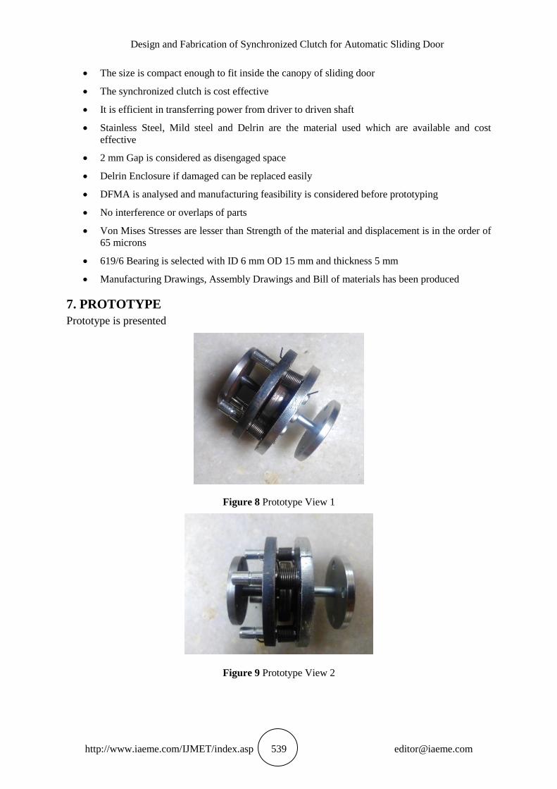
7. PROTOTYPE
Prototype is presented
Figure 8 Prototype View 1
Figure 9 Prototype View 2

D.L. Belgin Paul, M. Karthick, A. Sathesh Kumar
http://www.iaeme.com/IJMET/index.asp 540 [email protected]
8. CONCLUSIONS
Thus the Design and Prototyping of Synchronized clutch for automatic sliding door has been
done. All specifications mentioned in product design specification are met. The Synchronized
clutch is useful in converting the automatic sliding door to manual and vice versa with respect
to power and without human interference and it is very much useful in low power
transmission system.
9. LITERATURE SURVEY
Mr. Vishal J. Deshbhratar, Mr. Nagnath U. Kakde, 2013, Design and Structural Analysis of
Single Plate Friction Clutch
Oladunmoye M. & Oluwatomi A.A. Obakin O, 2014 Design And Construction Of An
Automatic Sliding Door Using Infrared Sensor
Jeyakkannan , Shankar vignesh S , Prakash A , Subashnandha K , Purushothaman P, 2016
Electromagnetic Clutch
http://hooniverse.com/2014/04/29/synchromesh-gear-box-hows-that-work/
http://www.diehl.com/en/diehl-metall/products/synchronizer-rings.html
https://Manual_transmission#Dog_clutch
http://www.superstreetonline.com/how-to/transmission-drivetrain/impp-1109-synchromesh-
vs-dog-box/
https://Non-synchronous_transmission
http://www.mecholic.com/2016/01/friction-clutch-types-applications-material-used.html
http://apac.stanleysecuritysolutions.com/uploads/2013/10/181849176173.pdf
http://www.stanleyaccess.com/sites/default/files/Slide%20Door%20Systems%20Owner's%20
Manual.pdf
http://doorteam.ir/uploads/6c8bf0f0-fd22-40ad-8146-25177df7e23d.pdf
http://repairpal.com/problem-with-door-mechanism-in-electric-sliding-doors-992
http://sounak4u.weebly.com/friction-clutches.html
REFERNCES
[1] Arunachalam M, Arun Prakash R, Rajesh R 2014, A Typical Approach in Conceptual and
Embodiment Design of Foldable Bicycle
[2] H. Eleashy & M.S.Elgayyar Structural Synthesis of 6 Bar Mechanisms as Mechanically
Constrained 3R Chains
[3] M F Ashby and D Cebon 2011, Materials Selection in Mechanical Design
[4] Evangelos Triantaphyllou, Stuart H Mann, Using The Analytic Hierarchy Process For
Decision Making In Engineering Applications: Some Challenges
[5] Nilesh Kailas More, Rajesh B. Buktar, Syed Mubasheer Ali, Sanjay Samant 2015 Design
For Manufacture And Assembly (Dfma) Analysis Of Burring Tool Assembly
[6] Gabriel Paramo Bermudez, Juan Alejandro García, Benitez Lozano 2015 Product design
‘pecification methodology for building a device foil incremental deformation by double
point method Dieless-DPIF
[7] Milica Stojanovic 2013, Multi Criteria Decision Making for Selection of renewable
energy systems
Design and Fabrication of Synchronized Clutch for Automatic Sliding Door
http://www.iaeme.com/IJMET/index.asp 541 [email protected]
[8] J Ando, H Ando, T Tsuda, K Suziki, Y Niikawa, Development of Third Generation
Electronically controlled AWD Coupling with New High Performance Electromagnetic
clutch
[9] Zongyi Zuo, Kaiping Feng, Bing Chen, 2003, The Modern Education Mode for
Engineering Drawing
[10] http://www.learnengineering.org/2012/12/theories-of-failure.html
[11] https://www.springmasters.com/extension-springs/
[12] http://www.acxesspring.com/extension-spring-design-guide.html
[13] http://faculty.mae.carleton.ca/John_Hayes/5507Notes/Ch3JH.pdf
[14] http://ebooks.library.cornell.edu/k/kmoddl/pdf/013_006.pdf
[15] https://www.cs.cmu.edu/~rapidproto/mechanisms/chpt4.html
[16] http://www.staff.city.ac.uk/~ra600/ME2105/Lectures/ME2104-11.pdf
[17] http://ccl.northwestern.edu/2014/AbrahamsonLindgren-embodiment-and-embodied-
design-in-press_%202.pdf
[18] General Tolerance ISO 2768
[19] ASM Material Data Sheet AISI 304
[20] Von Mises Criterion of theories of failure web.mae.ufl.edu>nkim>VonMisesCriterion
[21] Hexagonal Socket Cap Fastener ISO 4762 DIN 912
[22] SKF Roller Bearing Catalogue, Deep groove Ball Bearing
[23] ISO 7200 technical product documentation data fields in title blocks and document
headers
[24] ISO 5457 technical product documentation sizes and layout of drawing sheets
[25] ISO 13485 Medical Devices Quality Management Systems Requirement for regulatory
purpose
[26] Ameya R. Salunke and Prof. Nishant S. Kulkarni, Analysis of Friction Induced Vibration
during Engagement of Clutches. International Journal of Mechanical Engineering and
Technology, 7(3), 2016, pp. 285–298.
[27] K. Subbaiyan, V. Kalaiyarasan and M. AbdulGhaniKhan, Experimental Investigations and
Weld Characteristics Analysis of Single Pass Semiautomatic TIG Welding with Disimilar
Stainless Steels, International Journal of Mechanical Engineering and Technology, 8(5),
2017, pp. 545-555.