Embed Size (px)
Citation preview

10
Combination Clutch/Brake
10
Combination Clutch/Brake
For metalforming equipment
Fast, smooth cycling
Cool running with higher torque
Compact disc design
Simple Installation
The Wichita combination Clutch-Brakeprovides fast, smooth cycling for stampingpresses and metalforming equipment.The simple Wichita air tube conceptcombines an air actuated clutch and aspring-set brake in a compact disc design.
Multiple mounting optionsfor compatability withother competitive designs
Friction drive platessupplied in split form forease of installation
Long life air tube.No O-rings
Asbestos freefriction material
Precisiondie springs
Low stressinternal splineeliminates pins
Extra fins formaximum heat dis-sipation
Optional shrink-dischub for ease ofinstallation andremoval. No keyways required.
All air connections areexternal. Optionalquick release valvesavailable for fastercycling
Design Advantages• No shaft seals for faster, lower cost
installation
• Optional shrink disc mounting for simplified, easier installation
• Cool running for faster cycle rates,higher torques
• Models 380-910 have a single air-tubedesign that provides long life and highreliability
This cut-a-way shows Model 380-910 design
New larger inlets forCCB size 675-910 fora more rapid clutchand brake response
External locking nut on air inlet to increaseair tube life
®
DIST. AUTORIZADOMEX (55) 53 63 23 31QRO (442) 1 95 72 60
MTY (81) 83 54 10 [email protected]

11
A
11
OperationThe Wichita Combination Clutch/Brakeprovides fast, smooth cycling for stampingpresses and metalforming equipment.
The simple air-tube concept combines anair actuated clutch and spring-set brakein a compact, pancake assembly thatprevents overlap. The extra fins andcooling slots allow for excellent heatdissipation. A low stress spline eliminatesdriving pins between the shaft andcenterplate, while the precision die springsprovide consistent long-life braking action.
The high performance air-tube design insizes 380 and above, with optional quickair-release valves, provides faster cyclingthan piston and cylinder models. There areno o-rings or piston seals to wear-out andleak and no lubrication or adjustment isnecessary. Worn friction plates can berelined at Wichita’s factory on an ex-change basis.
Installation of the CCB is also easy. Thesimple air system has external connectionsand requires no shaft seals. Metric mount-ing and SAE fasteners are standard.Available in eight sizes with an optionalhub for shrink disc mounting. Clutchcapacities through 340,000 lb/in andbrake torque through 250,000 lb/in.
Wichita Combination Clutch/Brakes aremanufactured and assembled in theUnited States and backed by a globalsales, service and distributor organization.
Typical Applications
Wichita CCB is ideal for retrofit applications.
The simple externalair system with
quick release valvesprovides smooth,
fast cycling.
OptionalOptional shrink disc hub provides easeof mounting with no keyways.
®
DIST. AUTORIZADOMEX (55) 53 63 23 31QRO (442) 1 95 72 60
MTY (81) 83 54 10 [email protected]

12
Combination Clutch/Brake
12
Combination Clutch/Brake
Clutch/brake selectionA typical Combination Clutch/Brakeapplication would be on a geared punchpress. To properly select a CCB the followingapplication information is needed.
1. To determine the proper ApplicationDuty Factor for a Geared Punch Press,consult page 16. Under Duty “B” orNormal, the Duty Factor is 1-1/2.
2. To determine the application clutchtorque, the following information isneeded:
a. Torque @ Crank= (Rated Tonnage) (2000 lb./ton)(Torque Arm)
b. Torque Arm = y = (c) (tan a)c = a + b - x= 3 + 36 - .25= 38.75 in.
b2 + c2 - a2Cos α =
2bc(36)2 + (38.75)2 - (3)2
= (2) (36) (38.75)
= .99948
= 1.8478°
c. Torque Arm = y = (c) (tan α)
= (38.75) (tan 1.8478)= (38.75) (.03226)= 1.25 in.
Torque @ Crank
= (Rate Tonnage) (2000 lb./ton)(Torque Arm)= (200) (2000) (1.25)= 500,000 lb.in.
Required Torque @ Clutch
(Torque @ Crank) x (Crankshaft rpm)= lb.in.Clutch Shaft RPM
(500,000) (30)= lb.in.204
= 73,529 lb.in.
Application DataPress Type. . . . . . . . . . . Geared Punch PressRated Tonnage . . . . . . . . . . . . . . . . 200 tonsCrankshaft Speed . . . . . . . . . . . . . . . 30 rpmDegrees of Crank to Start . . . . . . . . . . . . 90°Distance Above Bottom – x . . . . . . . . .25 in.1/2 of Press Stroke (throw) = a . . . . . . . . 3 in.WR2 of Parts on Backshaft . . . . . . . . 78 lb.ft.2
Required Clutch Torque. . . . . . . 73,529 lb.in.Stroke . . . . . . . . . . . . . . . . . . . . . . . . . . . 6 in.Clutch/Brake Shaft . . . . . . . . . . . . . 204 rpmDegrees of Crank to Stop . . . . . . . . . . . . 120Connecting rod length = b . . . . . . . . . 36 in.WR2 of Parts on Crankshaft. . . . 39,091 lb.ft.2
Cycles/Minute . . . . . . . . . . . . . . . . . . . . . . . 7Air Pressure Available. . . . . . . . . . . . . 100 psiShaft Size . . . . . . . . . . . . . . . . . . . . . . . 4.5 in.
SelectionPress clutch and brake selection is based on:
1. Application Duty Factor2. Application clutch torque.3. Application brake torque necessary
to stop.4. Maximum Energy Input5. Heat generated during cycling.6. Bore size.
1/4" OffBottomDead
Centerx
c
y
Throw of Crank = a
36" ConnectingRod = b
3"
BullgearCrankshaft
CCB
Pinion
Flywheel
Motor
1/4" distance above bottom
®
DIST. AUTORIZADOMEX (55) 53 63 23 31QRO (442) 1 95 72 60
MTY (81) 83 54 10 [email protected]

13
A
13
combination clutch/brake.
a. Kinetic Energy = (WR2)(CCB rpm)2
5,873
KE = (1041)(204)2= 7,365 ft.lbs.
5,873
b. Maximum energy input to the CCB 600is 14,229 ft.lbs. Therefore, CCB 600 hassufficient energy input capacity.
5. To determine the Heat Horsepower Capacity of the CCB at backshaft speed you need the following information:
a. Heat hp capacity of CCB 600 @ 200 rpm. (Look up capacity under the 200rpm heading on page 16.)
Heat hp = 3.7 Heat hp @ 200 rpm.
b. To determine the Cycles Per Minute Capacity you need the following information:
(Heat hp @ CCB speed) (1.9 x 10⁸)
(WR2) (rpm)2
or 3.7 (1.9 x 10⁸)
(1041) (204)2
= 16 cpm
Final Selection:CCB 600 with 1/2 spring compliment. Alsoavailable with shrink disc shaft mounting.(See pages 18–19 for various mountingarrangments).
Note:This application example is for preliminary sizing only. Contact a Wichita Sales Engineer or the factory for final selection.
( )
Application selection torque = therequired torque of 73,529 lb.in. x 1.5 = 110,294 lb.in. (Application Duty Factor for“Geared Punch Press”, page 16.
Preliminary selection of CCB based onclutch torque is the CCB 600 with 50%spring compliment. The clutch torque forthis model is 124,350 lb.in. @ 80 psi.
d. Maximum bore for CCB 600 is 5.0 in. boreacceptable.
3. To determine application brake torquenecessary to stop the equipment thefollowing information is needed:
a. The inertia of rotating parts referred to thebackshaft. It is given in the applicationdata that the inertia (WR2) of parts on thecrankshaft is 39,091 lb.ft.2 at 30 rpm. Tocalculate WR2 referred to the backshaft:
30 rpm of Crankshaft 2
x 39,091 lb.ft.2204 rpm of Backshaft
= 845 lb.ft.2 @ 204 rpm
Total WR2 referred to backshaft is:
845 lb.ft.2 + 78 lb.ft.2 = 923 lb.ft.2
(WR2 of parts on backshaft fromapplication data)
Total WR2 to start and stop is:
923 lb.ft.2 + 118 lb.ft.2 = 1041 lb.ft.2
(WR2 of CCB-600 from page 15)
b. The brake stop time required is 120°.(Based on rotation at 30 rpm).
Angle to Stop 60Stop Time =
360 crankshaft rpm120 60
= = .5 sec360 30
c. Required deceleration torque =(WR2) (CCB rpm) (1041) (204)
or(23) (Stop Time Sec.) (23)(.5)
= 16,590 lb.in.
d. Application brake torque = (18,466) (1.5) or 27,700 lb.in.
The CCB 600 has a rated brake torque capacity of 35,850 lb.in.with 50% spring compliment.
4. Calculate energy input required for the
®
DIST. AUTORIZADOMEX (55) 53 63 23 31QRO (442) 1 95 72 60
MTY (81) 83 54 10 [email protected]

14
Combination Clutch/Brake
14
SpecificationsSize 380 thru 910
Clutch MaximumDynamic Brake Swept Maximum Speed
Slip Torque Dynamic Friction Energy (Balance)Spring Capacity Slip Torque Area Input (Speed)*
CCB Compliment @ 80 PSI** Capacity in2 ft.lbs. RpmModel % lb.in. (Nm) lb.in. (Nm) (cm2) (Joules) (Rpm)
100% 23,000 (2,600) 18,000 (2,030)380 75% 27,500 (3,100) 13,500 (1,525) 60 4,640 1,550
50% 32,000 (3,600) 9,000 (1,015)(387) (6,290) (895)
25% 36,500 (4,120) 4,500 (505)
100% 43,400 (4,900) 34,500 (3,890)470 75% 52,000 (5,870) 25,900 (2,920) 120 9,280 1,250
50% 60,650 (6,845) 17,250 (1,945)(774) (12,581) (725)
25% 69,275 (7,800) 8,625 (975)
100% 68,100 (7,685) 54,000 (6,095)550 75% 81,600 (9,210) 40,500 (4,570) 184 14,229 1,060
50% 95,100 (10,735) 27,000 (3,050)(1,187) (19,291) (620)
25% 108,600 (12,260) 13,500 (1,525)
100% 88,500 (9,900) 71,700 (8,090)600 75% 106,425 (12,000) 53,775 (6,070) 184 14,229 970
50% 124,350 (14,035) 35,850 (4,045)(1,187) (19,291) (570)
25% 142,275 (16,060) 17,925 (2,220)
100% 132,000 (14,900) 105,400 (11,910)675 75% 158,350 (17,875) 79,050 (8,930) 308 23,818 860
50% 184,700 (20,845) 52,700 (5,955)(1,987) (32,291) (500)
25% 211,050 (23,820) 26,350 (2,975)
100% 173,210 (19,570) 156,220 (17,652)760 75% 214,550 (24,240) 117,165 (13,236) 360 27,839 765
50% 255,900 (28,915) 78,110 (8,826)(2,323) (37,743) (450)
25% 291,115 (32,890) 39,055 (4,415)
100% 254,500 (28,750) 199,000 (22,480)830 75% 309,700 (34,990) 149,300 (16,870) 404 31,241 700
50% 337,300 (38,110) 124,400 (14,055)(2,606) (42,356) (410)
25% 392,500 (44,345) 74,600 (8,430)
100% 346,800 (39,150) 258,400 (29,160)910 75% 411,400 (46,430) 193,800 (21,870) 462 35,726 640
50% 476,000 (52,725) 129,200 (14,580)(2,981) (48,437) (375)
25% 540,600 (66,000) 64,600 (7,290)
Max. operating pressure Pmax= 100 PSI/7 bar. 1 bar=14.5 psig.
* For continuous running only. In the case of high speeds, it is necessary to balance the unit.
** For dry running only, it is essential to keep the friction surfaces free of lubricants.
®
DIST. AUTORIZADOMEX (55) 53 63 23 31QRO (442) 1 95 72 60
MTY (81) 83 54 10 [email protected]

15
Maximum Bores ‘R’ TotalTwin Rect. Internal External Weight
Square Key Keys Shrink Disc Parts Parts CCB in. in. in. Inertia Inertia (RR Style)Model (mm) (mm) (mm) lb.ft.2 (kgm2) lb.ft.2 (kgm2) lb. (kg)
380 2-7/8 3-3/16 3-1/8 12.4 (.52) 4 (0.17) 99 (45)
(73) (81) (80)
470 3-3/8 3-3/4 4-1/8 33.3 (1.4) 16 (0.67) 190 (86)
(86) (95) (105)
550 4-1/2 4-3/4 5-1/2 70.2 (3.0) 23 (0.97) 290 (132)
(114) (121) (140)
600 5 5 6-3/32 118 (5.0) 72 (3.0) 380 (172)
(127) (127) (155)
675 5 5-1/2 6-3/32 209 (8.8) 80 (3.4) 530 (240)
(127) (140) (155)
760 6-3/10 6-7/8 7-7/8 370 (15.6) 154 (6.5) 760 (345)
(160) (175) (200)
830 6-7/8 7-1/2 8-15/32 455 (19.2) 226 (9.5) 635 (288)
(175) (191) (215)
910 7-1/8 8-3/8 9-1/4 820 (34.5) 280 (11.8) 1190 (540)
(181) (213) (235)
®
DIST. AUTORIZADOMEX (55) 53 63 23 31QRO (442) 1 95 72 60
MTY (81) 83 54 10 [email protected]

16
Application Duty FactorsDuty B Duty C Duty D
Normal – Factor Heavy – Factor Extra Heavy – FactorField of Application 1-1/2 3-1/4 5-1/2
Metal Production Press Brake Shear Forming Press& Forming Non-Geared Punch Press Back Geared Punch Press Forging Press
Flywheel Drive* Double Back Shaft Drive* Header PressGeared Punch Press Deep Draw Press Knuckle Press
Single Back Shaft Drive*Single Reduction Drive* Transfer PressSingle Gear Drive* Toggle Press
* Alternate common industry name for above machine type
Heat Horsepower CapacitySpeed – RPM
CCB 100 200 300 400 500 600 700 800 900
170 .12 .16 .20 .23 .25 .27 .28 .30 .31
190 .16 .21 .25 .28 .30 .32 .34 .35 .36
230 .28 .35 .42 .45 .48 .51 .54 .58 .61
310 .51 .63 .74 .84 .93 .98 1 1.07 1.12
380 1 1.3 1.6 1.8 1.9 2 2 2.4 2.7
470 1.7 2.1 2.4 2.8 3.1 3.4 3.6 3.9 4.2
550 2.5 3.0 3.5 3.9 4.3 4.7 5.1 5.6 6
600 3 3.7 4.3 4.9 5.5 5.9 6.2 6.6 7
675 3.7 4.4 5 5.8 6.5 7.1 7.6 8.1 *
760 5 6.1 7.1 7.7 8.3 8.9 9.5 * *
830 6.5 7.9 9.3 10.2 11.1 11.9 12.7 * *
910 8 9.8 11.5 12.8 14 15.2 * * *
*Beyond maximum speed limit
Combination Clutch/Brake
®
DIST. AUTORIZADOMEX (55) 53 63 23 31QRO (442) 1 95 72 60
MTY (81) 83 54 10 [email protected]

17
A
17
Component PartsSize 380 thru 910
1. Hub
2. Bolt
3. Back Plate
4. Center Plate
5. Drive Plate
6. Air-Tube Holding Plate
7. Pressure Plate
8. Air-Tube
9. Air-Tube Holding Plate Bolts
10. Shim
11. Brake Springs
12. End Cap
13. Short Mounting Bracket
14. Long Mounting Bracket
29. Hex Head Cap Screw (HHCS)
30. Flex Lock Nuts
31. Socket Head Cap Screw (SHCS)
32. Hex Head Cap Screw
33. Air Spud
34. Air Manifold
35. Socket Head Cap Screw (SHCS)
Not Shown:
• Bolt & Nut between PressurePlate and Center Plate
• Clip, Bolt & Nut on Ring Mount
15. Drive Pin (Round Clutch)
16. Drive Pin (Square Clutch)
17. Drive Pin (Square Brake)
18. Drive Pin (Round Brake)
19. Drive Bushing (Round Clutch)
20. Drive Bushing (Square Clutch)
21. Drive Bushing (Square Brake)
22. Drive Bushing (Round Brake)
23. Snap Ring
24. Snap Ring
25. Snap Ring
26. Snap Ring
27. Retainer Plate (Brake Drive Pin)
28. Retainer Plate (Clutch Drive Pin)
1
2
3
5
67 8
9
10
4
11
12 34 31
35
30
2622
14
32
182724
25191328
29
1523
30
32 30
2328 16
13 20 25
29
2417
1421 26
30
32
®
DIST. AUTORIZADOMEX (55) 53 63 23 31QRO (442) 1 95 72 60
MTY (81) 83 54 10 [email protected]

19
A
18
Combination Clutch/Brake
19
C, C1, C2 dimensions are ± .007Model A Max (.18)
No. Bore* B B1 B2 C C1 C2 D E E1 E2 G G1+.000/ +.001/ +.001/ RR PP-.002 -.000 -.000
380 3.543 17.13 22.05 26.77 16.063 19.488 25.000 14.94 0.709 1.181 0.866 3.24 4.32(90) (435) (560) (680) (408) (495) (635) (380) (18) (30) (22) (82.2) (109.7)
470 3.740 21.06 27.36 33.66 19.685 24.016 31.102 18.50 0.984 1.575 1.181 4.02 4.88(95) (535) (695) (855) (500) (610) (790) (470) (25) (40) (30) (102.1) (124.0)
550 4.331 24.41 30.71 37.40 22.992 27.362 34.843 21.65 0.984 1.575 1.181 5.06 6.42(110) (620) (780) (950) (584) (695) (885) (550) (25) (40) (30) (128.4) (163.1)
600 4.921 26.77 34.25 42.32 25.197 30.315 38.976 23.62 1.181 1.772 1.575 4.83 6.22(125) (680) (870) (1075) (640) (770) (990) (600) (30) (45) (40) (122.6) (158.0)
675 5.519 30.51 39.37 48.56 28.543 34.646 44.685 26.57 1.378 2.165 1.772 5.39 6.98(140) (775) (1000) (1235) (725) (880) (1135) (675) (35) (55) (45) (136.9) (177.3)
760 6.299 34.06 42.91 52.56 31.890 38.189 48.622 29.92 1.575 2.165 1.772 5.96 7.50(160) (865) (1090) (1335) (810) (970) (1235) (760) (40) (55) (45) (151.4) (190.5)
830 7.087 37.50 49.31 63.09 — 43.307 57.087 32.68 1.772 2.954 2.560 7.19 8.75(180) (953) (1252) (1602) — (1100) (1450) (830) (45) (75) (65) (182.6) (222.3)
910 7.087 40.35 52.76 65.75 37.992 46.457 60.039 35.82 1.772 2.953 2.559 7.43 9.61(180) (1025) (1340) (1670) (965) (1180) (1525) (910) (45) (75) (65) (188.7) (244.1)
Dimensions (mm)
Lengths (mm) ThreadModel K L N1 N2 O P R S S1 S2 T1 T2 J U1 U2
No. Qty. Size
380 4 1/2" NPT 4.41 1.00 1.00 0.47 2.05 0.96 0.75 2.36 1.77 0.79 0.63 3/8–16 NC #10–24 NC #10–24 NC(112) (25) (25) (12) (52.0) (45.5) (19) (60) (45) (20) (16)
470 4 1/2" NPT 5.50 1.378 1.00 0.41 2.60 1.12 0.87 3.15 2.36 1.06 0.79 1/2–13 NC 1/4–20 NC #10–24 NC(140) (35) (25) (10.5) (66.5) (28.5) (22) (80) (60) (27) (20)
550 4 1/2" NPT 6.30 1.378 0.984 0.51 3.17 1.34 1.18 3.15 2.36 1.06 0.79 1/2–13 NC 1/4–20 NC #10–24 NC(160) (35) (25) (13.0) (80.5) (34) (30) (80) (60) (27) (20)
600 4 1/2" NPT 7.28 1.378 1.378 0.49 3.19 1.32 1.06 3.54 3.15 1.16 1.06 5/8–11 NC 5/16–18 NC 1/4–20 NC(185) (35) (35) (12.5) (81.0) (33.5) (27) (90) (80) (29.5) (27)
675 4 1" NPT 8.00 1.772 1.378 0.49 3.88 1.42 1.25 4.33 3.54 1.52 1.16 3/4–10 NC 5/16–18 NC 1/4–20 NC(203) (45) (35) (12.5) (98.5) (36) (32) (110) (90) (38.5) (29.5)
760 4 1" NPT 9.06 1.772 1.378 0.49 4.23 1.59 1.50 4.33 3.54 1.52 1.16 7/8–9 NC 5/16–18 NC 1/4–20 NC(230) (45) (35) (12.5) (107.5) (40.5) (38) (110) (90) (38.5) (29.5)
830 4 1" NPT 8.00 1.75 1.75 0.50 4.32 1.94 1.75 5.91 5.12 1.71 1.71 1–8 NC 5/16–18 NC 5/16–18 NC(203) (45) (45) (12.7) (109.7) (49.3) (44.5) (150.1) (130) (43.5) (43.5)
910 3 1" NPT 10.24 2.362 1.772 0.89 4.90 2.10 1.75 5.91 5.12 2.07 1.71 1–8 NC 3/8–16 NC 5/16–18 NC(260) (60) (45) (22.5) (124.5) (53.5) (44.5) (150) (130) (52.5) (43.5)
* Maximum bores with square key. Larger bores available with shallow keys.Note: For mounting, use socket head cap screws conforming to the ASTM-574-97a.
18
Combination Clutch/Brake
RP (Ring to Pin)RR (Ring to Ring)*
PP (Pin to Pin)** Dimensions same as RP design
All ring drives to have pins located in pin size counterbores 0.13" deep.
W
I C H I T A
MA
DEINUS
A
B2
C2
B
N2
B1
C1
N1
T1
S1S2T2
P
U2
U1
E1
E2
D
O
L
K
FlywheelReferencePlane
Brake Pin InFrame/Bracket
FlywheelReference PlaneFlywheel
Reference Plane
Flywheel
Bushing
Clutch Drive Plate
Brake Drive Plate
Frame/Bracket
Clutch Pin In Flywheel
C2
B2
C1
B1
R
G
J
OL
D
CS
E
B
U1
E1
G1 S1
DOL
C1
B1
U1
Size 380 thru 910
PEP
(Pin to Extended Pin)
RR
(Ring to Ring)
PP
(Pin to Pin)
®
DIST. AUTORIZADOMEX (55) 53 63 23 31QRO (442) 1 95 72 60
MTY (81) 83 54 10 [email protected]

20
Combination Clutch/Brake
20
Combination Clutch/Brake
C
D
B
A
E
F-RightHand Threads
Manifold
End Cap
End Cap Air Manifold
Model Kit No. A B C D E F
.875 H.C. 1/2 NPT380 8-546-021-000-1 4.188 3.12 N/A 13/32 Drill 4 at 90° 1" - 14 NF
3 at 120°
1.250 H.C. 1/2 NPT470 8-547-021-000-1 4.188 3.12 N/A 13/32 Drill 4 at 90° 1"-14 NF
3 at 120°
4.937 / 3.000 H.C. 2.000 H.C. 1/2 NPT550 8-549-021-000-1 4.935 3.12 13/32 Drill 13/32 Drill 4 at 90° 1-1/2" - 12 NF
3 at 120° 3 at 120°
2.875 H.C. 1/2 NPT600 8-552-021-000-1 4.938 3.12 13/32 Drill N/A 4 at 90° 1-1/2"-12 NF
3 at 120°
2.875 H.C. 1/2 NPF675 8-552-021-000-1 4.938 3.12 13/32 Drill N/A 4 at 90° 1-1/2"-12 NF
3 at 120°
3.500 H.C. 1/2 NPT760 8-553-021-000-1 7.000 3.12 N/A 13/32 Drill 4 at 90° 1-1/2"-12 NF
3 at 120°
4.000 H.C. 1" NPT830 4-555-021-000-3 9.50 4.06 N/A 9/16 Drill 4 at 90˚ 1-1/2"-12 NF
4 at 90˚
7.255 / 5.000 H.C. 3.250 H.C. 1/2 NPT910 8-554-021-000-1 7.250 3.12 17/32 Drill 17/32 Drill 6 at 60° 2"-12 NF
3 at 120° 3 at 120°
Minimum Maximum Roto-Clearance W+ Wear Tank Vol. Pipe Size Coupling*
Model in. mm in. mm K+ in. mm in.3 liters in. mm Part No.
380 1/32 0.8 0.1 2.5 86 0.12 3 100 1.6 3/4 19 8-240-708-001-1
470 1/32 0.8 0.1 2.5 134 0.16 4 155 2.5 3/4 19 8-240-708-001-1
550 3/64 1.2 0.11 2.8 196 0.20 5 250 4.1 1 32 8-240-710-002-1
600 3/64 1.2 0.11 2.8 215 0.20 5 275 4.5 1 32 8-240-710-002-1
675 1/16 1.6 0.12 3.2 280 0.25 6 390 6.4 1 32 8-240-710-002-1
760 1/16 1.6 0.12 3.2 360 0.25 6 500 8.2 1 32 8-240-710-002-1
830 3/32 2.4 0.16 4 489 0.25 6 800 13.1 1-1/2 38 8-240-710-002-1
910 3/32 2.4 0.16 4 530 0.28 7 1000 16.4 1-1/2 38 8-240-712-001-1
*See page 27 for dimensions
Clearance & Wear Chart
®
DIST. AUTORIZADOMEX (55) 53 63 23 31QRO (442) 1 95 72 60
MTY (81) 83 54 10 [email protected]

21
A
21
* Optional Quick Release Valves can replace elbows on most units.
Air Hose Kits for Sizes 380 thru 910
Hose Kit for Air Manifold or Cross Drilled Shaft Mounting
Model Part Number
380 8-938-812-402-5 ELB8-938-820-401-5 QRV
470 8-947-812-402-5 ELB8-947-820-401-5 QRV
550 8-955-812-402-5 ELB8-955-820-401-5 QRV
600 8-960-812-402-5 ELB8-960-820-401-5 QRV
675 8-967-812-402-5 ELB8-967-820-401-5 QRV
760 8-976-812-402-5 ELB8-976-820-401-5 QRV
830 8-983-813-401-5 ELB8-983-831-401-5 QRV
Hose Kit for Shrink Disc Mid-Shaft Mounting
Model Part Number
380 8-938-812-401-5 ELB8-938-822-401-5 QRV
470 8-947-812-401-5 ELB8-947-822-401-5 QRV
550 8-955-812-401-5 ELB8-955-822-401-5 QRV
600 8-960-812-401-5 ELB8-960-822-401-5 QRV
675 8-967-812-401-5 ELB8-967-822-401-5 QRV
760 8-976-812-401-5 ELB8-976-822-401-5 QRV
830 8-983-813-402-5 ELB8-983-831-402-5 QRV
Wichita Air Hose Kits contain all the necessary parts(fittings, hoses and extensions) to completely plumbthe brake air system. The Hose Kit part number is determined by model number, type of shaft mounting and whether or not a quick release valve is needed.
Hose Kit for Shrink Disc Mid-Shaft Mounting
Model Part Number
910 8-991-812-503-5 ELB8-991-822-503-5 QRV
Hose Kit for Air Manifold or Cross Drilled Shaft Mounting
Model Part Number
910 8-991-812-502-5 ELB8-991-820-501-5 QRV
®
DIST. AUTORIZADOMEX (55) 53 63 23 31QRO (442) 1 95 72 60
MTY (81) 83 54 10 [email protected]

22
Combination Clutch/Brake
22
Combination Clutch/Brake
SpecificationsSize 170 thru 310
For cyclic applications use 60% of torque rating.
ClutchDynamic Brake ‘R’ Total Cylinder
Slip Torque Dynamic Internal External Weight VolumeCapacity Slip Torque Maximum Parts Parts New
CCB @ 80 PSI Capacity Speed Inertia Inertia (RR Style) WornModel lb.in. (Nm) lb.in. (Nm) (RPM) lb.ft.2 (kgm2) lb.ft.2 (kgm2) lb. (kg) in3 (cm3)
170/13 1150 (130) 1330 (150)170/17 1505 (170) 975 (110) 3450 0.31 (0.013) 0.095 (0.004) 11.9 (5.4) 2.45 (40)
170/21 1815 (205) 665 (75) 3.65 (60)
170/25 2170 (245) 310 (35)
190/21 1815 (205) 2125 (240)190/27 2345 (265) 1595 (180) 3050 0.57 (0.024) 0.14 (0.006) 17.0 (7.7) 3.35 (55)
190/33 2880 (325) 1060 (120) 5.20 (85)
190/39 3410 (385) 530 (60)
230/41 3630 (410) 4120 (465)230/53 4650 (525) 3100 (350) 2425 1.78 (0.075) 0.47 (0.020) 31.1 (14.1) 5.50 (90)
230/64 5670 (640) 2080 (235) 8.85 (145)
230/76 6690 (755) 1060 (120)
310/92 8100 (915) 9300 (1050)310/118 10,450 (1180) 6950 (785) 1875 5.24 (0.221) 1.42 (0.060) 61.1 (27.7) 10.10 (165)
310/144 12,750 (1440) 4650 (525) 16.80 (275)
310/171 15,100 (1705) 2300 (260)
®
DIST. AUTORIZADOMEX (55) 53 63 23 31QRO (442) 1 95 72 60
MTY (81) 83 54 10 [email protected]
2825
1519
1423
30
26 29 24
26
30
2213
31
25
27
18
8
4
7 5
6
9
3026
30
1
3
11
2
31
1321
1725
27
2314202528
16 24
23
A
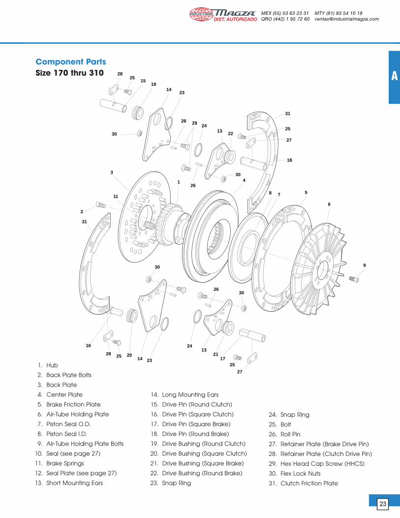
23
1. Hub
2. Back Plate Bolts
3. Back Plate
4. Center Plate
5. Brake Friction Plate
6. Air-Tube Holding Plate
7. Piston Seal O.D.
8. Piston Seal I.D.
9. Air-Tube Holding Plate Bolts
10. Seal (see page 27)
11. Brake Springs
12. Seal Plate (see page 27)
13. Short Mounting Ears
14. Long Mounting Ears
15. Drive Pin (Round Clutch)
16. Drive Pin (Square Clutch)
17. Drive Pin (Square Brake)
18. Drive Pin (Round Brake)
19. Drive Bushing (Round Clutch)
20. Drive Bushing (Square Clutch)
21. Drive Bushing (Square Brake)
22. Drive Bushing (Round Brake)
23. Snap Ring
24. Snap Ring
25. Bolt
26. Roll Pin
27. Retainer Plate (Brake Drive Pin)
28. Retainer Plate (Clutch Drive Pin)
29. Hex Head Cap Screw (HHCS)
30. Flex Lock Nuts
31. Clutch Friction Plate
Component PartsSize 170 thru 310
®
DIST. AUTORIZADOMEX (55) 53 63 23 31QRO (442) 1 95 72 60
MTY (81) 83 54 10 [email protected]

24
Combination Clutch/Brake
24
Combination Clutch/Brake
Size 170 thru 310
Model A Max Lengths (mm)No. Bore B B1 B2 C C1 C2 D E E1 E2 W1 W2 L N1 N2
170 1.38 7.80 10.32 13.27 7.165 9.055 12.008 6.54 0.394 0.551 0.551 0.18 0.18 1.811 0.787 0.787(35) (198) (262) (337) (182) (230) (305) (166) (10) (14) (14) (4.5) (4.5) (46) (20) (20)
190 1.38 8.66 11.10 14.06 8.071 9.843 12.795 7.40 0.394 0.551 0.551 0.18 0.18 2.283 0.787 0.787(35) (220) (282) (357) (205) (250) (325) (188) (10) (14) (14) (4.5) (4.5) (58) (20) (20)
230 1.77 10.83 14.17 17.40 10.039 12.402 16.142 9.29 0.472 0.866 0.551 0.22 0.18 2.598 0.984 0.787(45) (275) (360) (442) (255) (315) (410) (236) (12) (22) (14) (5.5) (4.5) (66) (25) (20)
310 2.56 13.66 17.13 21.73 12.795 15.354 19.291 11.97 0.591 0.866 0.551 0.22 0.88 3.228 0.984 0.787(65) (347) (435) (522) (325) (390) (490) (304) (15) (22) (14) (5.5) (4.5) (82) (25) (20)
Dimensions (mm)
C, C1, C2 dimensions are ± .007(.18)
C
I
W
H I TA
CB
310
B2
C2
N2
T2
C1
B1
W1
W2N1
T1
B
C
Note: For mounting, use socket head cap screws conforming to the ASTM-574-97a.
®
DIST. AUTORIZADOMEX (55) 53 63 23 31QRO (442) 1 95 72 60
MTY (81) 83 54 10 [email protected]

25
A
25
S1
U1V
E1
C D A
OL
P
S2
U2
E2
R
S
E
J
O
S2
P1
E2U2
U1
S1E1
O1
PEP DesignPin to
Extended Pin
RP DesignRing to
Extended Pin
RP DesignRing to Pin
Model Lengths (mm) Thread No. O O1 P P1 R S S1 S2 T1 T2 V J U1 U2
170 0.079 0.217 0.866 1.004 0.236 0.433 0.984 0.984 0.433 0.433 0.118 M5 M4 M4(2) (5.5) (22) (25.5) (6) (11) (25) (25) (11) (11) (3) (M5) (M4) (M4)
190 0.118 0.217 1.063 1.161 0.394 0.433 1.103 1.103 0.433 0.433 0 M5 M4 M4(3) (5.5) (27) (29.5) (10) (11) (28) (28) (11) (11) (0) (M5) (M4) (M4)
230 0.158 0.335 1.260 1.437 0.512 0.512 1.772 1.103 0.630 0.433 0.512 M6 M5 M4(4) (8.5) (32) (36.5) (13) (13) (45) (28) (16) (11) (13) (M6) (M5) (M4)
310 0.158 0.394 1.535 1.772 0.591 0.630 1.772 1.103 0.630 0.433 0.394 M8 M5 M4(4) (10) (39) (45) (15) (16) (45) (28) (16) (11) (10) (M8) (M5) (M4)
All ring mountings use 12 bushings ‘E’ diameter, equally spaced on ‘C’ pitch circle diameter.Non standard suspension plates may be available on request.
®
DIST. AUTORIZADOMEX (55) 53 63 23 31QRO (442) 1 95 72 60
MTY (81) 83 54 10 [email protected]

X
Air FeedDiameter
Keyway
Shaft Cross Drill
90°
26
Combination Clutch/Brake
26
Combination Clutch/Brake
A B C D1 D2 H1 H2 W1 W2 “O” Ringto BS 4518
CCB 170 44.5 69.4 10 52 80 1.8 2.3 2.4 3 0446-24 0695-30
CCB 190 44.5 69.4 10 52 80 1.8 2.3 2.4 3 0446-24 0695-30
CCB 230 57.5 89.4 10 65 100 1.8 2.3 2.4 3 0576-24 0695-30
CCB 310 79.4 109.4 10 88 120 2.3 2.3 3 3 0795-30 1095-30
Size 170 thru 310
Air Supply Dimensions
D1 A
C C 2
B D2
H2W2
W1
H1
1
Seal Plate Dimensions (mm)
Dimension Shaft Cross Air Feed Shaft EndX (mm) Drill (mm) Dia (mm) Tapping
CCB 170 31 4 7 5/8"-18NF
CCB 190 41 5 9 5/8"-18NF
CCB 230 47.5 6 9 5/8"-18NF
CCB 310 50 6 13 1"-14NF
Seals and seal platessupplied by customer
®
DIST. AUTORIZADOMEX (55) 53 63 23 31QRO (442) 1 95 72 60
MTY (81) 83 54 10 [email protected]

27
A
27
Quick Release Valve
8-263-610-011-1 7/8" – 14 Thread8-263-610-021-1 1/2" NPT
Quality MaterialBody and Cap: High strength aluminum alloy
Stem: Moulded nylonCheck Valve: Nylon ball
"O" Ring: Neoprene
The Wichita Springless Quick Release Valvedischarges twice as fast as any other valvetested in our laboratory and is four to fivetimes faster than some common makes ofvalves.
This valve will close and seal with less than 20lbs. pressure. Most others require 25 to 30 lbs.to definitely seal. In actual tests, the WichitaValve made many hundreds of thousands ofengagements and disengagements beforethe slightest leak occurred, or any partsneeded replacement. Other valves whichwere tested required major replacement infewer than 20,000 cycles.
Standard thread arrangement of 1/2" size.1/2" pipe thread on the tube connectionand choice of 1/2" pipe thread, or stan-dard 7/8-14NF thread for flared fittingthread on inlet connection. (Fits standardNo. 10 high-pressure hose fitting.)
2.95"
.88"
1/2" NPT (for Optional Muffler)
1/2" NPT to CLUTCH
7/8" – 14 Thread1/2" NPT
.2.2
1" .1.5
6"
Wichita Part No. AA B C D E F G H Max. R.P.M.
8-240-701-003-1 5/8-18NF 1/4" NPT .40 1.046 2.250 1.500 2.13 3.297 3500
8-240-705-001-1 1"-14 NF 1/2" NPT .75 1.250 3.188 2.500 3.00 4.438 3500
8-240-708-001-1 1"-14 NF 3/4" NPT .75 1.313 4.688 2.875 3.69 5.440 3500
8-240-710-002-1 1-1/2"-12 NF 1" NPT 1.13 1.937 4.875 3.250 3.44 6.812 2500
8-240-712-001-1 2"-12 NF 1-1/2" NPT 1.13 2.813 5.250 4.250 5.38 8.062 2500
8-240-714-001-3 2" NPT 2" NPT 1.50 3.000 7.062 4.625 7.00 10.062 1000
8-240-716-000-3 2-1/2" NPT 2-1/2" NPT 1.88 3.250 9.375 7.000 7.75 12.625 750
Note: All measurements are in inches.
D
C
E
G
H
AA F
B150 PSI Max. Air Pressure
The Wichita Roto-coupling is a device toconnect, or couple, a non-rotating air, gas,or fluid line to a rotating shaft.
• Long life, no maintenance.• Felt seal eliminates bearing contamination.• Fast, easy installation.
Roto-couplings
®
DIST. AUTORIZADOMEX (55) 53 63 23 31QRO (442) 1 95 72 60
MTY (81) 83 54 10 [email protected]


![Hannover Masse Web Upload - Drawings Cdonar.messe.de/.../electromagnetic-clutch-brake-combinations-eng-2… · Electromagnetic Clutch-Brake Combination TYPE 14.800. .10.3[8] & 12.3[8]](https://img.dokumen.tips/doc/110x75/5f4e4a19cad6165848446014/hannover-masse-web-upload-drawings-electromagnetic-clutch-brake-combination-type.jpg)


