Embed Size (px)
Citation preview
®
INSTALLATION MANUAL
CONVENTIONAL
F I R E PA N E L S
424
408
ISO 140019191.BNT2
ISO 14001IT-52588
ISO 90019105.BNT1
ISO 9001IT-52587
OHSAS 180019192.BSEC
OHSAS 18001IT - 60983

This Control panel can be programmed using the respective Software J400 release 1.1 or higher.
BENTEL SECURITYsrl shall not assume the responsibility for damage arising from improper application or use.
This Control panel has been designed and manufactured to the highest standards of quality and performance.
Installation of this Control panel must be carried out strictly in accordance with the instructions described in this manual, and
in compliance with the local laws and bylaws in force
The J424 and J408 Control panels comply with the essential requirements of standards EN54-2; EN54-4; EN12094-1.
EN12094-1 certification shall be deemed void if the J400-EXT Extinguishment Module is not installed in the Control panel.
BENTEL SECURITY srl reserves the right to change the technical specifications of these products without prior notice.
Recycling information
BENTEL SECURITY recommends that customers dispose of their
used equipments (panels, detectors, sirens, and other devices) in an
environmentally sound manner. Potential methods include reuse of
parts or whole products and recycling of products, components,
and/or materials.
For specific information see:
www.bentelsecurity.com/en/environment.htm
Waste Electrical and Electronic Equipment (WEEE) Di-rective
In the European Union, this label indicates that this
product should NOT be disposed of with household wa-ste. It should be deposited at an appropriate facility to
enable recovery and recycling.
For specific information see:
www.bentelsecurity.com/en/environment.htm
EN12094-1
Electrical automatic control and delay device
Environmental class A
Protection level IP30
Flooding zones 1 to 4
CO2, inert gas, halogenate hydrocarbon
Expected Options:
– Delay of extinguishing signal
Response delay activated condition: maximum 3 s
– Monitoring of status of components
– Emergency hold device
– Control of flooding time
Response delay triggering of outputs: maximum 1 s
0051-CPD-0197 (J400-EXT in J424)
(J400-EXT in J408-2/J408-4/J408-8)0051-CPD-0196
09
0051
BENTEL SECURITY s.r.l.
Via Gabbiano, 22 - Zona Ind. S. Scolastica
64013 Corropoli (TE) - ITALY
0051
0051 - CPD - 0192
0051 - CPD - 0193
0051 - CPD - 0194
0051 - CPD - 0195
EN 54-2 1997+A1 2006: :
Control and indicating equipment for fire detection and fire alarm
systems for buildings.
09
(J408-2)
(J408-4)
(J408-8)
(J424)
BENTEL SECURITY s.r.l.
Via Gabbiano, 22 - Zona Ind. S. Scolastica
64013 Corropoli (TE) - ITALY
EXPECTED
: type C
OPTIONS
Dependencies on more than one alarm signal
Delays to outputs
Test condition
Output to fire alarm devices
Output to fire alarm routing equipment

CONTENS
INTRODUCTION 5The J424 and J408 Control panels 5
Accessory Items 5
Description 5
Inputs 5
Outputs 6
Operating features 6
Interface 7
Extinguishment Module 8
Access to Signalling and Commands 8
Power Supply 8
IDENTIFICATION OF PARTS 9The Status LEDs 9
Description of Parts 14
Description of the Control keys 20
INSTALLING THE CONTROL PANEL 21Installing accessory boards 21
Installing Extinguishment Modules 21
Installing Expander Module Kit (for J424 ONLY) 22
Display Module (for J424 and J400-REP ONLY) 24
Installing Repeaters 25
Installing the Control panel 25
Description of the Terminals 25
Main Board and Expander Board terminals 25
Main Board Terminals 26
Extinguishment Module Terminals 28
The System Wiring 29
Connecting Fire Detectors 29
Connecting Call-points 30
Connecting Gas Detectors 30
Connecting Signalling Devices 32
Connecting a Repeater 32
Connecting Extinguishment Modules 33
Connecting a Dialler 34
Connecting a Power Supply 34
Connecting the Mains Supply 35
Thermal Probe 35
Maintenance 36
Testing the Extinguishment Module 36
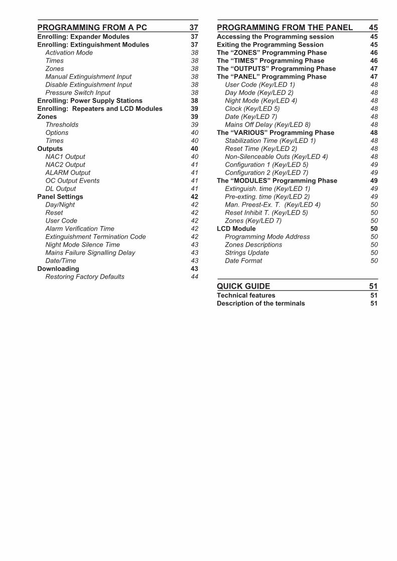
PROGRAMMING FROM A PC 37Enrolling: Expander Modules 37
Enrolling: Extinguishment Modules 37
Activation Mode 38
Times 38
Zones 38
Manual Extinguishment Input 38
Disable Extinguishment Input 38
Pressure Switch Input 38
Enrolling: Power Supply Stations 38
Enrolling: Repeaters and LCD Modules 39
Zones 39
Thresholds 39
Options 40
Times 40
Outputs 40
NAC1 Output 40
NAC2 Output 41
ALARM Output 41
OC Output Events 41
DL Output 41
Panel Settings 42
Day/Night 42
Reset 42
User Code 42
Alarm Verification Time 42
Extinguishment Termination Code 42
Night Mode Silence Time 43
Mains Failure Signalling Delay 43
Date/Time 43
Downloading 43
Restoring Factory Defaults 44
PROGRAMMING FROM THE PANEL 45Accessing the Programming session 45
Exiting the Programming Session 45
The “ZONES” Programming Phase 46
The “TIMES” Programming Phase 46
The “OUTPUTS” Programming Phase 47
The “PANEL” Programming Phase 47
User Code (Key/LED 1) 48
Day Mode (Key/LED 2) 48
Night Mode (Key/LED 4) 48
Clock (Key/LED 5) 48
Date (Key/LED 7) 48
Mains Off Delay (Key/LED 8) 48
The “VARIOUS” Programming Phase 48
Stabilization Time (Key/LED 1) 48
Reset Time (Key/LED 2) 48
Non-Silenceable Outs (Key/LED 4) 48
Configuration 1 (Key/LED 5) 49
Configuration 2 (Key/LED 7) 49
The “MODULES” Programming Phase 49
Extinguish. time (Key/LED 1) 49
Pre-exting. time (Key/LED 2) 49
Man. Preest-Ex. T. (Key/LED 4) 50
Reset Inhibit T. (Key/LED 5) 50
Zones (Key/LED 7) 50
LCD Module 50
Programming Mode Address 50
Zones Descriptions 50
Strings Update 50
Date Format 50
QUICK GUIDE 51Technical features 51
Description of the terminals 51
INTRODUCTION
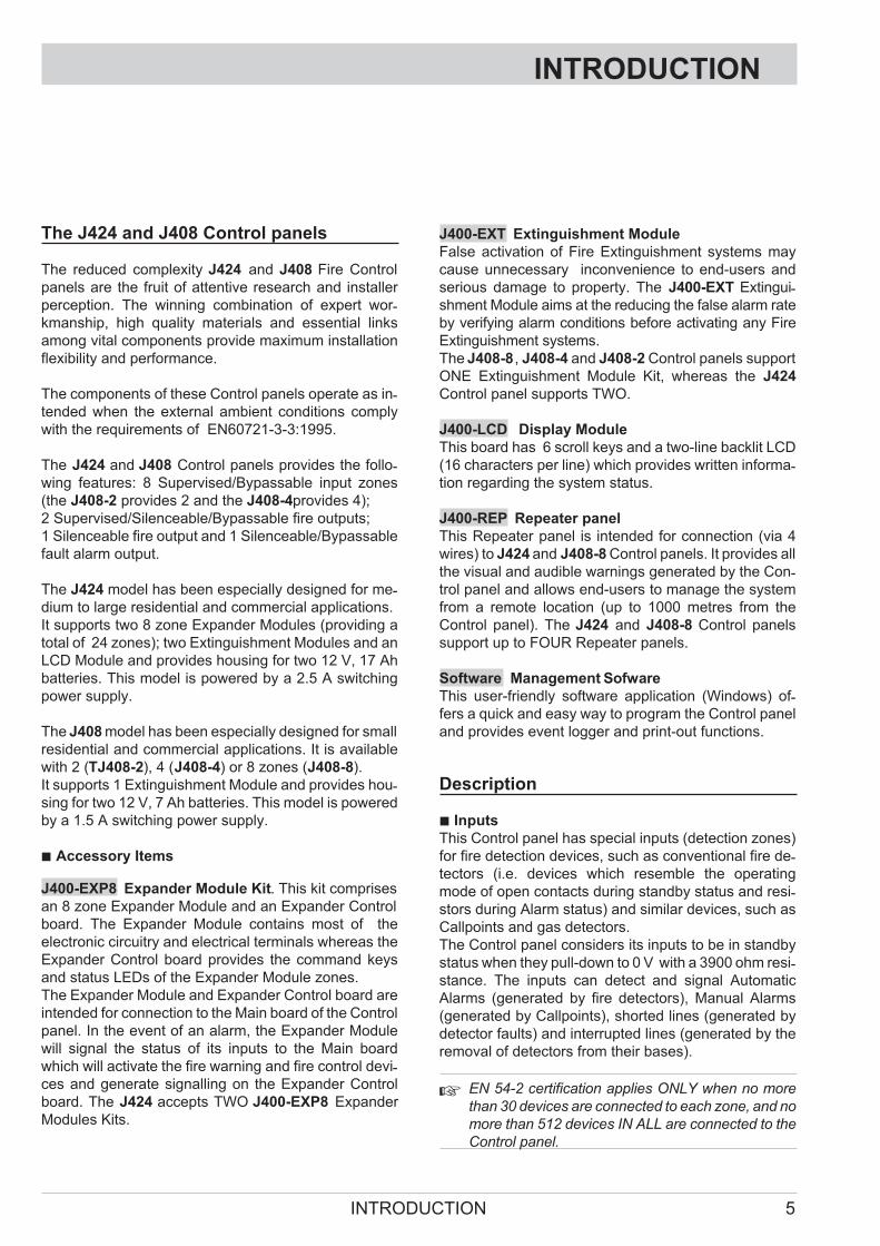
The J424 and J408 Control panels
The reduced complexity J424 and J408 Fire Control
panels are the fruit of attentive research and installer
perception. The winning combination of expert wor-kmanship, high quality materials and essential links
among vital components provide maximum installation
flexibility and performance.
The components of these Control panels operate as in-tended when the external ambient conditions comply
with the requirements of EN60721-3-3:1995.
The J424 and J408 Control panels provides the follo-wing features: 8 Supervised/Bypassable input zones
(the J408-2 provides 2 and the J408-4provides 4);
2 Supervised/Silenceable/Bypassable fire outputs;
1 Silenceable fire output and 1 Silenceable/Bypassable
fault alarm output.
The J424 model has been especially designed for me-dium to large residential and commercial applications.
It supports two 8 zone Expander Modules (providing a
total of 24 zones); two Extinguishment Modules and an
LCD Module and provides housing for two 12 V, 17 Ah
batteries. This model is powered by a 2.5 A switching
power supply.
The J408 model has been especially designed for small
residential and commercial applications. It is available
with 2 (TJ408-2), 4 (J408-4) or 8 zones (J408-8).
It supports 1 Extinguishment Module and provides hou-sing for two 12 V, 7 Ah batteries. This model is powered
by a 1.5 A switching power supply.
� Accessory Items
J400-EXP8 Expander Module Kit. This kit comprises
an 8 zone Expander Module and an Expander Control
board. The Expander Module contains most of the
electronic circuitry and electrical terminals whereas the
Expander Control board provides the command keys
and status LEDs of the Expander Module zones.
The Expander Module and Expander Control board are
intended for connection to the Main board of the Control
panel. In the event of an alarm, the Expander Module
will signal the status of its inputs to the Main board
which will activate the fire warning and fire control devi-ces and generate signalling on the Expander Control
board. The J424 accepts TWO J400-EXP8 Expander
Modules Kits.
J400-EXT Extinguishment Module
False activation of Fire Extinguishment systems may
cause unnecessary inconvenience to end-users and
serious damage to property. The J400-EXT Extingui-shment Module aims at the reducing the false alarm rate
by verifying alarm conditions before activating any Fire
Extinguishment systems.
The J408-8 , J408-4 and J408-2 Control panels support
ONE Extinguishment Module Kit, whereas the J424
Control panel supports TWO.
J400-LCD Display Module
This board has 6 scroll keys and a two-line backlit LCD
(16 characters per line) which provides written informa-tion regarding the system status.
J400-REP Repeater panel
This Repeater panel is intended for connection (via 4
wires) to J424 and J408-8 Control panels. It provides all
the visual and audible warnings generated by the Con-trol panel and allows end-users to manage the system
from a remote location (up to 1000 metres from the
Control panel). The J424 and J408-8 Control panels
support up to FOUR Repeater panels.
Software Management Sofware
This user-friendly software application (Windows) of-fers a quick and easy way to program the Control panel
and provides event logger and print-out functions.
Description
� Inputs
This Control panel has special inputs (detection zones)
for fire detection devices, such as conventional fire de-tectors (i.e. devices which resemble the operating
mode of open contacts during standby status and resi-stors during Alarm status) and similar devices, such as
Callpoints and gas detectors.
The Control panel considers its inputs to be in standby
status when they pull-down to 0 V with a 3900 ohm resi-stance. The inputs can detect and signal Automatic
Alarms (generated by fire detectors), Manual Alarms
(generated by Callpoints), shorted lines (generated by
detector faults) and interrupted lines (generated by the
removal of detectors from their bases).
� EN 54-2 certification applies ONLY when no more
than 30 devices are connected to each zone, and no
more than 512 devices IN ALL are connected to the
Control panel.
INTRODUCTION 5

� Outputs
� This Control panel accepts devices that operate
within SELV limits ONLY.
This section describes how the Control panel outputs
operate.
Supervised outputs The Control panel will be able to
detect and signal short-circuits and power supply inter-ruptions on this type of output.
Bypassable outputs The user will be able to disable
(by means of the respective key) this type of output.
Silenceable outputs The user will be able to stop (via
the Silence key) this type of output
The outputs can be silenced for an indefinite period (du-ring Day Mode) or, for the programmed Silence Time
(during Night Mode).
This Control panel provides the following alarm outputs:
� two Supervised/Silenceable/Bypassable outputs
(NAC1 and NAC2 terminals) with positive polarity
(27.6 V) during alarm status;
� one Silenceable/NON-Supervised/NON-Bypassable
Volt-free changeover contact (ALARM terminals) for
devices which cannot be connected directly to NAC1
or NAC2;
� one Supervised/Bypassable/NON-Silenceable output
(DL terminal), intended for use with telephone devices
that pull-down to 0 V (negative) in the event of an alarm;
� one Silenceable/NON-Supervised/NON-Bypassable
output for each input zone (terminals R1, R2, ..., R8)
that will pull-down to 0 V (negative) when the respecti-ve zone generates an alarm. These outputs allow se-lective action, as they activate only the devices
connected to the zone concerned.
�The NAC1, NAC2 and DL outputs comply with
EN54-2.
This Control panel also provides:
� one Silenceable/NON-Supervised/NON-Bypassable
Volt-free changeover contact (TROUBLE terminals)
that will activate in the event of trouble;
� one NON-Supervised/NON-Bypassable/NON-Silen-ceable open-collector output (OC terminal) that will
pull-down to 0 V (negative) when the associated
event occurs (Alarm, Pre-alarm, Fault, Reset,
Bypass, Test or Double knock);
� one NON-Supervised/NON-Bypassable/NON-Silen-ceable changeover contact (PL terminal) that will
pull-down to 0 V (negative) in the event of power fai-lure to the Control panel.
� Operating features
Pre-alarm If a zone generates an alarm during Day
Mode (Night Mode LED OFF), the Control panel will start
the Pre-alarm Time. This status will be signalled by:
� a slow intermittent beep;
� blinking on the LED of the Zone Alarm that genera-ted the Alarm;
� glowing on the Pre-al. LED;
� activation of the NAC1 and NAC2 outputs — in ac-cordance with programming;
� Negative pull-down to 0 V on the R terminal of the
zone that generated the Alarm, that is, if the
Pre-alarm on R output option is enabled;
� Negative pull-down to 0 V on OC terminal, that is, if it
is programmed to signal Pre-alarm.
� This Control panel will generate an Instant Alarm if
alarm conditions are detected during Night Mode
(Night Mode LED glowing) or, if an alarm is trigge-
red from a Callpoint connected to a zone enabled
for Call point Priority (i.e. the Call point Priority
option ENABLED).
During Pre-alarm status, all persons on the premises
(Access Level 1 — refer to “Access to signalling and
commands”) will be able to:
� activate an Evacuation Alarm by pressing and hol-
ding the Ack./Evac. key for AT LEAST 5 seconds.
During Pre-alarm status, Key and PIN Code users
(Access Level 2 — refer to “Access to signalling and
commands”) will be able to:
� add the Investigation Time to the Pre-Alarm Time
by pressing (for LESS THAN 5 seconds) the
Ack./Evac. key;
� activate an Evacuation Alarm by pressing and hol-
ding the Ack./Evac. key for AT LEAST 5 seconds;
� stop the Silenceable outputs and interrupt the
Pre-alarm Time by pressing the Silence key.
During Silence status (Silence LED glowing), it is pos-sible to use the Silence key to release the Silenceable
outputs and restart Pre-alarm Time or, use the Reset
key to restore standby status.
�If the Control panel is operating in Night Mode
(Night Mode LED glowing), the Control panel will
exit Silence status automatically when the pro-grammed Night mode Silence time expires.
Alarm The Control panel will generate an alarm when the
Pre-Alarm Time expires. Alarm status will be signalled by:
� a fast intermittent beep;
� glowing on the LED of the Zone Alarm that genera-
ted the Alarm;
� glowing on the Alarm LED;
� activation of the NAC1 and NAC2 outputs — in ac-cordance with programming;
� Negative pull-down to 0 V on the R terminal of the
zone that generated the Alarm;
6 Conventional Fire Panels J424/J408

� Negative pull-down to 0 V on the OC terminal, that is,
if it is programmed to signal Alarm status.
�The Control panel will activate the DL output when
the programmed Alarm Signalling delay expires.
During Alarm status, Key and PIN Code users (Access
Level 2 — refer to “Access to signalling and com-mands”) will be able to:
� stop the Silenceable outputs by pressing the Silence key.
During Silence status (Silence LED glowing), it is pos-sible to use the Silence key to release the Silenceable
outputs, and the Reset key to restore standby status.
� If the Control panel is in Night Mode (Night Mode
LED glowing), the Control panel will exit Silence
status when the programmed Night mode Silence
time expires.
Trouble This Control panel can detect and signal the
following Trouble:
� Input zone shorted or open;
� Supervised zone shorted or open;
� Control panel blocked;
� Output 24V or 24R shorted;
� Low battery, battery trouble or disconnected battery;
� Ground fault;
� Communication trouble with peripherals;
� Mains failure.
Fault conditions will be signalled by:
� a slow intermittent beep (at 1 second intervals);
� glowing on the Fault LED;
� fast blinking on the LED of the “component” concer-ned (the Logic Unit LED will glow to signal “Control
panel blocked”);
� activation of the Fault output (TROUBLE terminals);
� Negative pull-down to 0 V on OC terminal, that is, if it
is programmed to signal Fault.
The Fault output (TROUBLE terminals) and OC out-puts (if duly programmed by your Installer) will restore
to standby automatically when fault conditions clear.
Under certain circumstances, fault conditions may clear
spontaneously, if this occurs, the event will be stored in
the memory until the Control panel Resets.
Stored Fault events will be signalled by:
� slow blinking on the LEDs of the “component” con-cerned.
Silence This Control panel provides a Silence key
which can be used to restore the Silenceable outputs to
standby status:
� R1, R2, ..., R8
� NAC1 and NAC2
� ALARM
� TROUBLE
Silence status will be signalled by:
� an audible signal (lasting 1 second) followed by a
long pause (lasting 5 seconds);
� glowing on the Silence LED.
Silence status will be held until the Silence key is pres-sed again or, if the Control panel is operating in Night
Mode, until the programmed Night mode Silence time
expires, or until a new Alarm or Trouble condition is de-tected.
� ONLY Key and PIN Code Users (Access Level 2)
can SILENCE the Silenceable outputs.
Disable This Control panel provides keys which can
be used to disable the bypassable inputs and outputs:
� Z1, Z2, ... Z24 can be used to bypass (exclude) their
respective zones;
� Disab./Fault NAC can be used to bypass outputs
NAC1 and NAC2;
� Disab./Fault Telecom can be used to bypass the DL
output.
DISABLED zones cannot generate alarms or warnings
of any kind, and DISABLED outputs cannot be activa-ted.
Disabled status will be signalled by:
� glowing on the Disab. LED;
� glowing on the LED of the respective zone or output
(see LEDs: Disabled/Fault/Test, Disab./Fault NAC
and Disab./Fault Telecom).
� ONLY Key and PIN Code Users (Access Level 2)
can DISABLE zones and/or outputs.
Reset Resetting the Control panel will restore the out-puts to standby status, delete the memory, and interrupt
the power supply to terminals Z1, Z2, ..., Z8 and 24R for
the programmed Reset Time.
�ONLY Key and PIN Code Users (Access Level 2)
can Reset the system. Fire alarms must be Silen-ced (via the Silence key) before Reset.
Fault conditions can be Reset directly (via the Re-set key).
� Interface
Visual Signalling The system status will be signalled
on the Control panel LEDs as follows:
GREEN indicates normal operating conditions;
AMBER indicates specific operating modes (for exam-ple Day or Night mode), and/or Fault conditions;
RED indicates Alarm conditions.
Memory The Control panel will signal Alarm/Fault
events until the system Resets, even if the event clears
in the meantime.
Stored events will be signalled by:
� slow blinking on the LED concerned.
Display The J424 Control panel can house the
J400-LCD Module. This module provides written infor-mation regarding the system status, and the cause of
faults on inputs and outputs (short-circuit, interruption
etc.).
INTRODUCTION 7
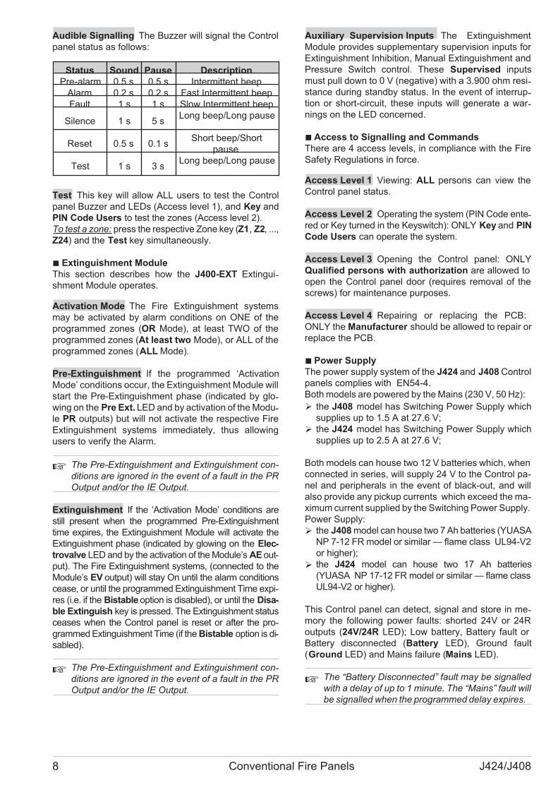
Audible Signalling The Buzzer will signal the Control
panel status as follows:
Status Sound Pause Description
Pre-alarm 0.5 s 0.5 s Intermittent beep
Alarm 0.2 s 0.2 s Fast Intermittent beep
Fault 1 s 1 s Slow Intermittent beep
Silence 1 s 5 sLong beep/Long pause
Reset 0.5 s 0.1 sShort beep/Short
pause
Test 1 s 3 sLong beep/Long pause
Test This key will allow ALL users to test the Control
panel Buzzer and LEDs (Access level 1), and Key and
PIN Code Users to test the zones (Access level 2).
To test a zone: press the respective Zone key (Z1, Z2, ...,
Z24) and the Test key simultaneously.
� Extinguishment Module
This section describes how the J400-EXT Extingui-shment Module operates.
Activation Mode The Fire Extinguishment systems
may be activated by alarm conditions on ONE of the
programmed zones (OR Mode), at least TWO of the
programmed zones (At least two Mode), or ALL of the
programmed zones (ALL Mode).
Pre-Extinguishment If the programmed ‘Activation
Mode’ conditions occur, the Extinguishment Module will
start the Pre-Extinguishment phase (indicated by glo-wing on the Pre Ext. LED and by activation of the Modu-le PR outputs) but will not activate the respective Fire
Extinguishment systems immediately, thus allowing
users to verify the Alarm.
� The Pre-Extinguishment and Extinguishment con-
ditions are ignored in the event of a fault in the PR
Output and/or the IE Output.
Extinguishment If the ‘Activation Mode’ conditions are
still present when the programmed Pre-Extinguishment
time expires, the Extinguishment Module will activate the
Extinguishment phase (indicated by glowing on the Elec-
trovalve LED and by the activation of the Module’s AE out-
put). The Fire Extinguishment systems, (connected to the
Module’s EV output) will stay On until the alarm conditions
cease, or until the programmed Extinguishment Time expi-
res (i.e. if the Bistable option is disabled), or until the Disa-
ble Extinguish key is pressed. The Extinguishment status
ceases when the Control panel is reset or after the pro-
grammed Extinguishment Time (if the Bistable option is di-
sabled).
� The Pre-Extinguishment and Extinguishment con-ditions are ignored in the event of a fault in the PR
Output and/or the IE Output.
Auxiliary Supervision Inputs The Extinguishment
Module provides supplementary supervision inputs for
Extinguishment Inhibition, Manual Extinguishment and
Pressure Switch control. These Supervised inputs
must pull down to 0 V (negative) with a 3.900 ohm resi-stance during standby status. In the event of interrup-tion or short-circuit, these inputs will generate a war-nings on the LED concerned.
� Access to Signalling and Commands
There are 4 access levels, in compliance with the Fire
Safety Regulations in force.
Access Level 1 Viewing: ALL persons can view the
Control panel status.
Access Level 2 Operating the system (PIN Code ente-red or Key turned in the Keyswitch): ONLY Key and PIN
Code Users can operate the system.
Access Level 3 Opening the Control panel: ONLY
Qualified persons with authorization are allowed to
open the Control panel door (requires removal of the
screws) for maintenance purposes.
Access Level 4 Repairing or replacing the PCB:
ONLY the Manufacturer should be allowed to repair or
replace the PCB.
� Power Supply
The power supply system of the J424 and J408 Control
panels complies with EN54-4.
Both models are powered by the Mains (230 V, 50 Hz):
� the J408 model has Switching Power Supply which
supplies up to 1.5 A at 27.6 V;
� the J424 model has Switching Power Supply which
supplies up to 2.5 A at 27.6 V;
Both models can house two 12 V batteries which, when
connected in series, will supply 24 V to the Control pa-
nel and peripherals in the event of black-out, and will
also provide any pickup currents which exceed the ma-
ximum current supplied by the Switching Power Supply.
Power Supply:
� the J408 model can house two 7 Ah batteries (YUASA
NP 7-12 FR model or similar — flame class UL94-V2
or higher);
� the J424 model can house two 17 Ah batteries
(YUASA NP 17-12 FR model or similar — flame class
UL94-V2 or higher).
This Control panel can detect, signal and store in me-mory the following power faults: shorted 24V or 24R
outputs (24V/24R LED); Low battery, Battery fault or
Battery disconnected (Battery LED), Ground fault
(Ground LED) and Mains failure (Mains LED).
�The “Battery Disconnected” fault may be signalled
with a delay of up to 1 minute. The “Mains” fault will
be signalled when the programmed delay expires.
8 Conventional Fire Panels J424/J408
IDENTIFICATION OF PARTS
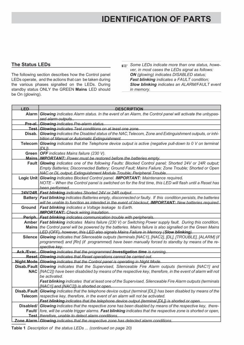
The Status LEDs
The following section describes how the Control panel
LEDs operate, and the actions that can be taken during
the various phases signalled on the LEDs. During
standby status ONLY the GREEN Mains LED should
be On (glowing).
�Some LEDs indicate more than one status, howe-ver, in most cases the LEDs signal as follows:
ON (glowing) indicates DISABLED status;
Fast blinking indicates a FAULT condition;
Slow blinking indicates an ALARM/FAULT event
in memory.
LED DESCRIPTION
Alarm Glowing indicates Alarm status. In the event of an Alarm, the Control panel will activate the unbypas-
sed alarm outputs..
Pre-al. Glowing indicates Pre-alarm status.
Test Glowing indicates Test conditions on at least one zone.
Disab. Glowing indicates the Disabled status of the NAC,Telecom, Zone and Extinguishment outputs, or inhi-
bition of Manual or Automatic Extinguishment
Telecom Glowing indicates that the Telephone device output is active (negative pull-down to 0 V on terminal
[DL]).
Green
Mains
OFF indicates Mains failure (230 V).
IMPORTANT: Power must be restored before the batteries empty.
Fault Glowing indicates one of the following Faults: Blocked Control panel; Shorted 24V or 24R output;
Empty Batteries; Disconnected Battery; Ground Fault; Mains Failure; Zone Trouble; Shorted or Open
NAC or DL output; Extinguishment Module Trouble; Peripheral Trouble.
Logic Unit Glowing indicates Blocked Control panel. IMPORTANT: Maintenance required.
NOTE – When the Control panel is switched on for the first time, this LED will flash until a Reset has
been performed.
24V/24R Fast blinking indicates Shorted 24V or 24R output.
Battery Fast blinking indicates Batteries empty, disconnected or faulty. If this condition persists, the batteries
will be unable to function as intended in the event of blackout, IMPORTANT: New batteries required
Ground Fast blinking indicates a Voltage leakage to Earth.
IMPORTANT: Check wiring insulation.
Periph. Fast blinking indicates communication trouble with peripherals.
Amber
Mains
Fast blinking indicates Mains failure (230 V) or Switching Power supply fault. During this condition,
the Control panel will be powered by the batteries. Mains failure is also signalled on the Green Mains
LED (OFF), however, this LED also signals Mains Failure in Memory (Slow blinking).
Silence Glowing indicates that Silenceable outputs (terminals [NAC1], [NAC2], [DL], [TROUBLE], [ALARM] (if
programmed) and [Rn] (if programmed) have been manually forced to standby by means of the re-
spective key.
Ack./Evac. Glowing indicates that the programmed Investigation time is running.
Reset Glowing indicates that Reset operations cannot be carried out.
Night Mode Glowing indicates that the Control panel is operating in Night Mode.
Disab./Fault
NAC
Glowing indicates that the Supervised, Silenceable Fire Alarm outputs (terminals [NAC1] and
[NAC2]) have been disabòled by means of the respective key, therefore, in the event of alarm will not
be activated.
Fast blinking indicates that at least one of the Supervised, Silenceable Fire Alarm outputs (terminals
[NAC1] and [NAC2]) is shorted or open.
Disab./Fault
Telecom
Glowing indicates that the telephone device output (terminal [DL]) has been disabled by means of the
respective key, therefore, in the event of an alarm will not be activated.
Fast blinking indicates that the telephone device output (terminal [DL]) is shorted or open.
Disabled/
Fault/
Test
Glowing indicates that the respective zone has been disabled by means of the respective key, there-
fore, will be unable trigger alarms. Fast blinking indicates that the respective zone is shorted or open,
therefore, unable to detect alarm conditions.
Zone Alarm Glowing indicates that the respective zone has detected alarm conditions.
Table 1 Description of the status LEDs ... (continued on page 20)
B
MSACMBLIJ424-80.0
Esc
Enter
Fault
LogicUnit
Battery
Ground
Mains
Periph.
Pre-al.
Disab.
Mains
Telecom
Test
Silence Night Mode
Ack./Evac. Disab./FaultNAC
Reset Disab./FaultTelecom
Disab. Buzzer Test
1 2 3
5
8
0
4
7
9
6
Disabled/Fult/Test Disabled/Fult/Test
z1 z5
z4 z8
z3 z7
z2 z6
Zone Alarm Zone Alarm
24V/24R
Alarm
Disabled/Fult/Test Disabled/Fult/Test
z9 z13
z12 z16
z11 z15
z10 z14
Zone Alarm Zone Alarm
Disabled/Fult/Test Disabled/Fult/Test
z17 z21
z20 z24
z19 z23
z18 z22
Zone Alarm Zone Alarm
®
424
Extinguish. AutomaticExtinguish.
ManualExtinguish.
Electro-valve
Pre-Ext.
ManualExt.
Disab.Ext.
Pres.Switch
LogicUnit
Disable
Fault
ON
Extinguish. AutomaticExtinguish
ManualExtinguish.
Electro-valve
PreExt.
ManualExt.
Disab.Ext.
Pres-Switch
LogicUnit
Disable
Fault
ON
Livello2
REP
1 2 1 2 3
2512
a)
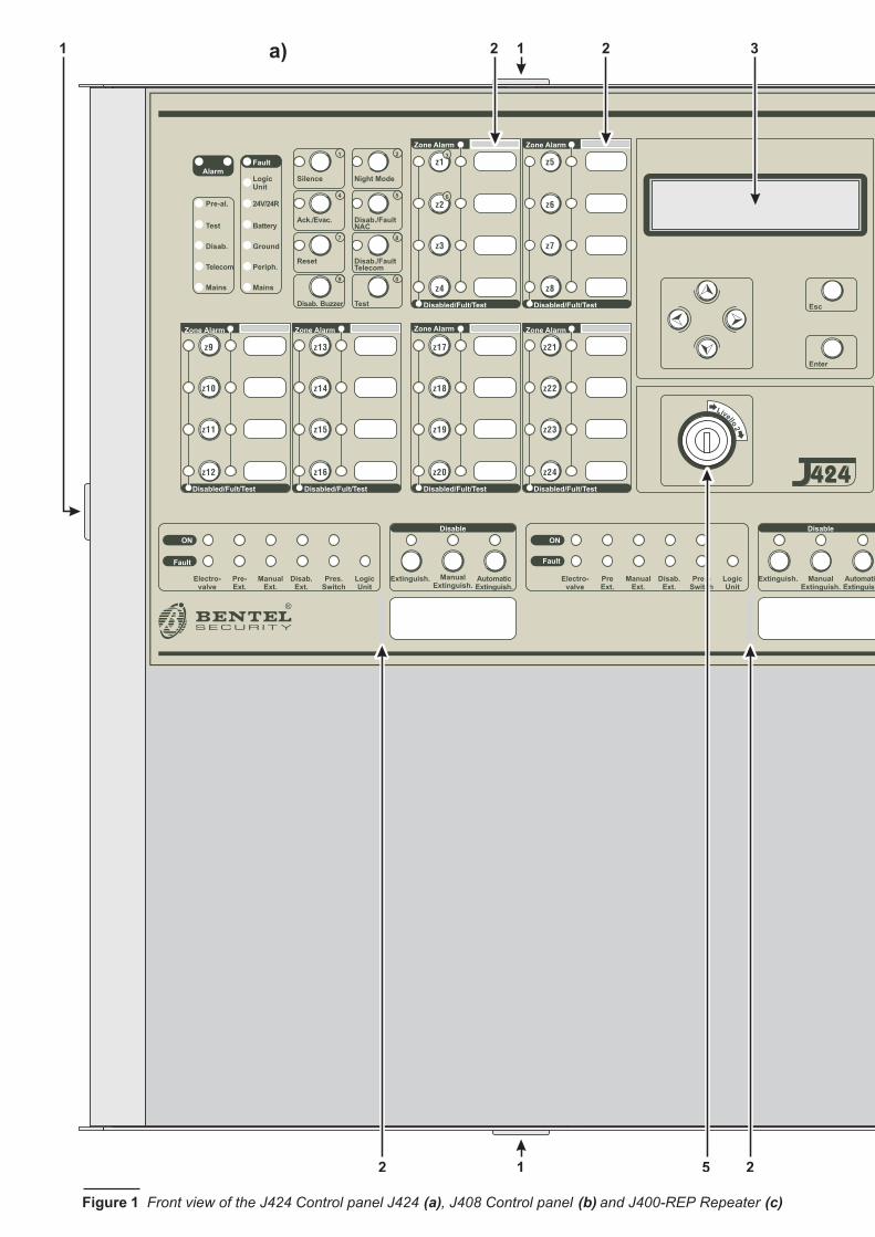
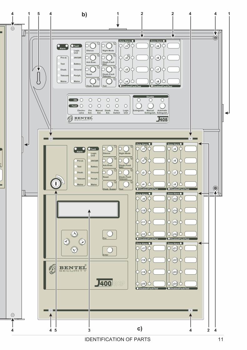
Figure 1 Front view of the J424 Control panel J424 (a), J408 Control panel (b) and J400-REP Repeater (c)
B
MSACMBLIJ408-80.0
Extinguish. AutomaticExtinguish.
ManualExtinguish.
Electro-valve
PreExt.
ManualExt.
Disab.Ext.
Pres.Switch
LogicUnit
Disable
Fault
ON
®
408
MSACMNEIJ408-80.0
Fault
LogicUnit
Battery
Ground
Mains
Periph.
Pre-al.
Disab.
Mains
Telecom
Test
Silence Night Mode
Ack./Evac. Disab./FaultNAC
Reset Disab./FaultTelecom
Disab. Buzzer Test
1 2 3
5
8
0
4
7
9
6
Disabled/Fault/Test Disabled/Fault/Test
z1 z5
z4 z8
z3 z7
z2 z6
Zone Alarm Zone Alarm
24V/24R
Alarm
ch.
MSACMBLIJ400-REPa.0
Esc
Enter
Fault
LogicUnit
Battery
Ground
Mains
Periph.
Pre-al.
Disab.
Mains
Telecom
Test
Silence Night Mode
Ack./Evac. Disab./FaultNAC
Reset Disab./FaultTelecom
Disab. Buzzer Test
1 2 3
5
8
0
4
7
9
6
Disabled/Fault/Test Disabled/Fault/Test
z1 z5
z4 z8
z3 z7
z2 z6
Zone Alarm Zone Alarm
24V/24R
Alarm
Disabled/Fault/Test Disabled/Fault/Test
z9 z13
z12 z16
z11 z15
z10 z14
Zone Alarm Zone Alarm
Disabled/Fault/Test Disabled/Fault/Test
z17 z21
z20 z24
z19 z23
z18 z22
Zone Alarm Zone Alarm
®
Livello2
400 REP
5 1 2 2 4
44
4 1 1b)4 4
4 435 2c)
IDENTIFICATION OF PARTS 11

C
NO
NC
6 7 8 10 11
262728293031
9
Figure 2 Maximum configuration of the J424 Control panel
Z1 R11 2 3
Z2 R24 5 6
Z3 R37 8 9
Z4 R410 11 12
DL
24
V
27
28
29
30
31
PL
AL
AR
M
NO
NC
C
TR
OU
BLE
NO
NC
C-
+-
+
NA
C1
NA
C2
Z5 R513 14 15
Z6 R616 17 18
Z7 R719 20 21
Z8 R822 23 24
26
24
RO
C
+-
RS
48
5
V 24
PRG
B016
GA
SE
F
R
AC
/NFG
+V
GN
D
B+
L
B–
GND
+V
AC
/L
F3
.1
5A
/2
5Ø
VF
6.
3A
/2
5Ø
V
20
12 13 14 15 17 14 18 12 19
21222324202512 12
16
IDENTIFICATION OF PARTS 13

Description of Parts
This section describes the components of the J424 and
J408 Control panels, and J400-REP Repeater.
Unless otherwise stated, the numbers in boldface in this
Manual refer to the Tables ands Diagrams in this sec-tion.
The parts identification numbers in the diagrams go cloc-kwise. The white numbers refer to parts which are com-mon to several of the system devices, therefore, are
described the first time they are encountered only.
P. Description
1 Surface Cable conduit entry
2 Zone label slots
3 Display
4 Door screws
5 Keyswitch (Access Level 2)
6 Display module (accessory item)
7 Expander Control board (LEDs and keys) of
Expander no. 2 (accessory item for J424)
8 Flat cable (accessory item for J424): for the
Expander Control board connection
9 Main Control board (LEDs and keys) of zones
1 through 8
10 Expander Control board (LEDs and keys) of
zones 9 through 16 (accessory item for J424)
11 Flat cable: for the Main Control Board connec-tion (zones 1 through 8)
12 Anchor screw locations
13 Main board (2, 4 or 8 zones)
14 Chased cable conduit entry
15 Flat cable (accessory item for J424): for the
Expander Control board connection
14 Conventional Fire Panels J424/J408
B
C
NO
NC
9
323228 27
11
Figure 3 Maximum configuration of the J408 Control panel

P. Description
16 Anchor for 230 V power supply wires
17 Switching power supply screws
18 Switching power supply/Battery charger
19 Switching power supply support
20 Batteries (NOT supplied!):
J408 = two 7 Ah @ 12 V
J424 = two 17 Ah @ 12 V
21 Expander no. 1 (accessory item)
22 Bag containing keys, resistors and diodes
23 Flat cable (accessory item): for the Expander
Module no. 1 to Expander Module no. 2 con-nection
24 Thermal probe
25 Expander Module no. 2 (accessory item)
26 Flat cable(accessory item): for the Expander
Module no. 1 to Main board connection
27 Flat cable (accessory item): for the Extingui-shment Module to Main board connection
28 Extinguishment Module no.1 (accessory
item)
P. Description
29 Flat cable (accessory item): for the Extingui-shment Module no. 1 to Extinguishment Mo-dule no. 2 connection
30 Flat cable (accessory item): for the Display
Module connection
31 Extinguishment Module no.2 (accessory
item)
32 Wire run
IDENTIFICATION OF PARTS 15
Z1 R1
1 2 3
Z2 R2
4 5 6
Z3 R3
7 8 9
Z4 R4
10 11 12
DL
24
V
27
28
29
30
31
PL
AL
AR
M
NO
NC
C
TR
OU
BLE
NO
NC
C-
+-
+
NA
C1
NA
C2
Z5 R5
13 14 15
Z6 R6
16 17 18
Z7 R7
19 20 21
Z8 R8
22 23 24
26
24R
OC
+-
RS
48
5
V 24
PRG
B016
GA
SE
F
R
AC
/NFG
+V
GN
D
B+
L
B–
GND
+V
AC
/L
F2
A/2
5Ø
V
F 6 . 3 A / 2 5 Ø V
B
12
13 12 18
202012 24
17 1916 14
22
P. Description
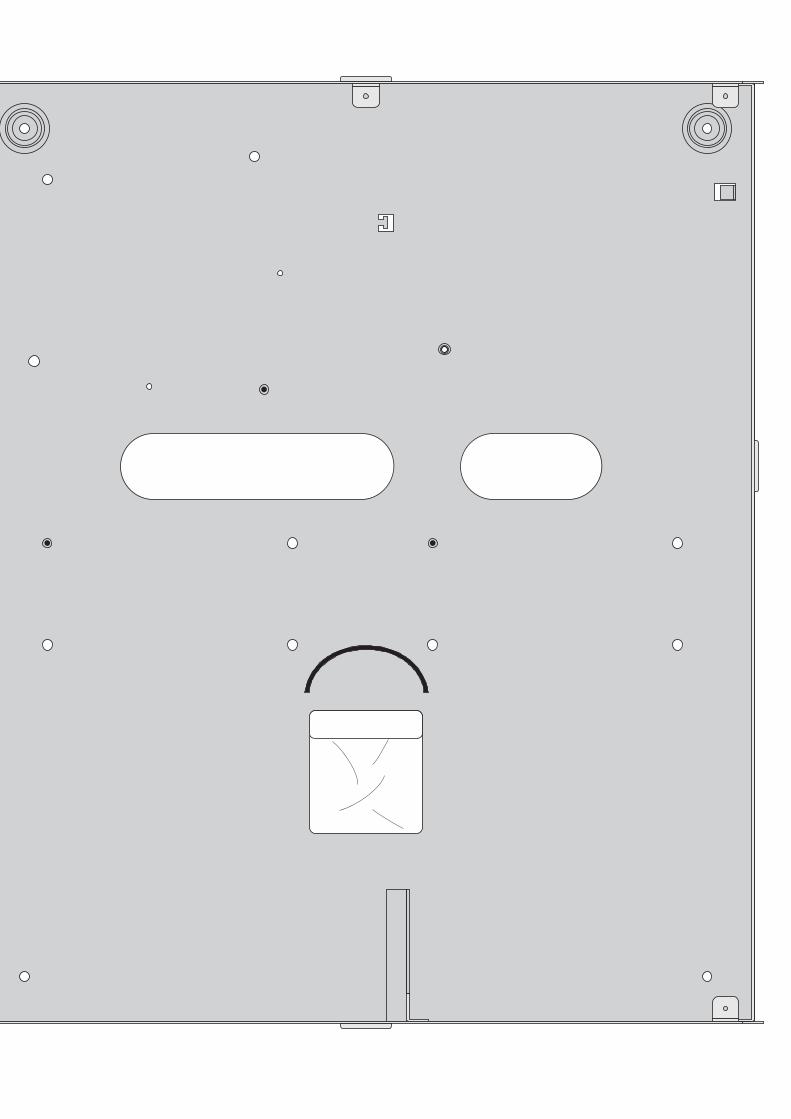
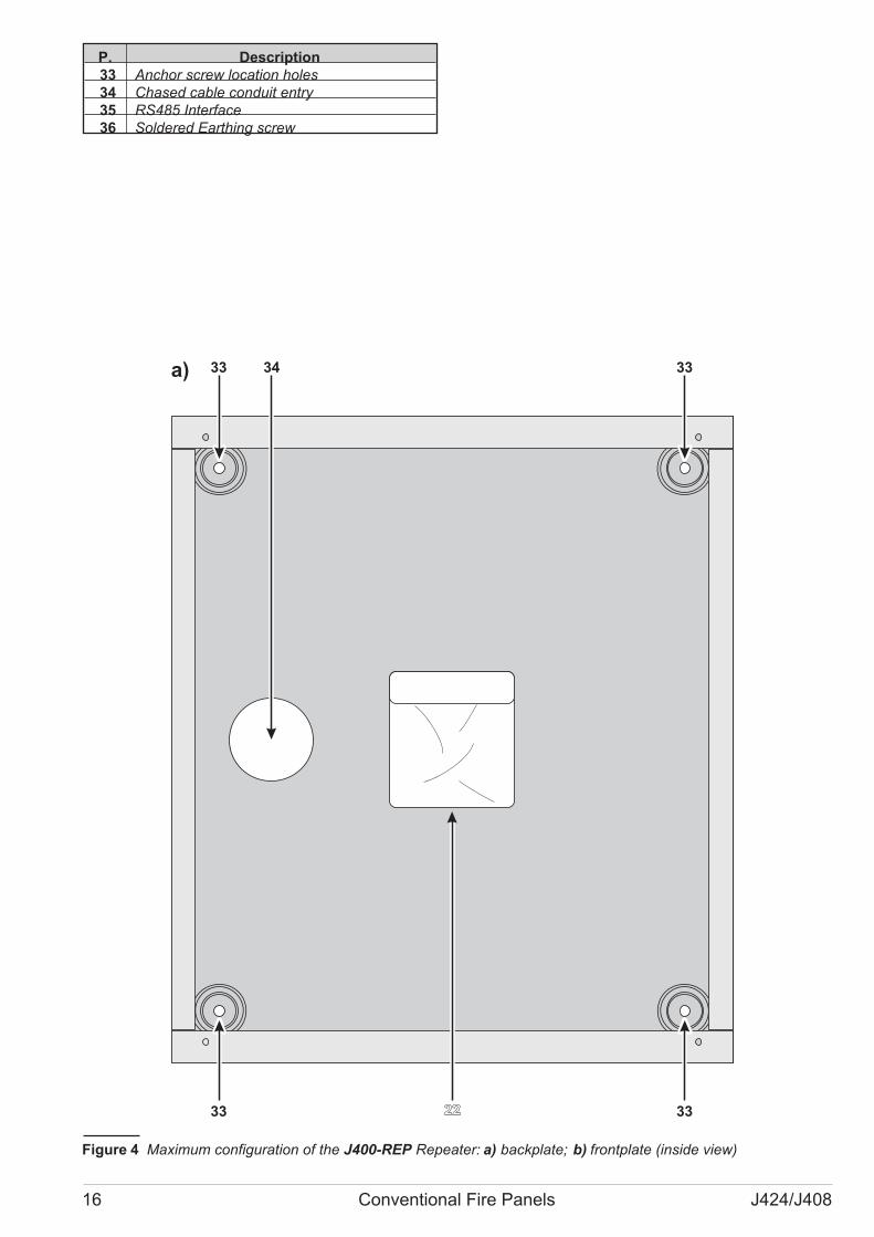
33 Anchor screw location holes
34 Chased cable conduit entry
35 RS485 Interface
36 Soldered Earthing screw
16 Conventional Fire Panels J424/J408
a) 33
33
34 33
33
Figure 4 Maximum configuration of the J400-REP Repeater: a) backplate; b) frontplate (inside view)

IDENTIFICATION OF PARTS 17
C
NO
NC
36 35
b)

P. Description
37 Battery output voltage control output (connec-ted at factory)
38 Thermal probe jack
39 Switching-power-supply jack (connected at
factory)
40 Buzzer
41 Terminal board
42 Extinguishment Module anchor holes
43 Address Jumper:
// = Extinguishment Module no. 1
oo = Extinguishment Module no. 2
44 Terminal board
45 Cable: connects the Switching power supply
to the Main board (connected at factory)
46 Switching-power-supply anchor
47 Switching-power-supply closure rivet
48 Mains indicator LED
49 Switching-power-supply anchor hole
50 Switching-power-supply output voltage con-trol input (connected at factory)
51 Fine trimmer for the Switching-power-supply
output Voltage
52 Auxiliary power-supply terminals (27.6 V)
53 Mains power terminals (230 V / 50 Hz)
54 Switching-power-supply screws
55 Switching-power-supply fuse — protects aga-inst overload:
J408 = F 2A 250V
J424 = F 3.15A 250V
56 Jack for Extinguishment Module nr. 2 or the
Display Module
57 Microprocessor
58 Jack for the Main board or Display Module
59 Reserved Jumper — DO NOT REMOVE
60 Battery jacks
61 Jumper for Ground (Earth) fault detection:
// = Ground (Earth) fault monitored
oo = Ground (Earth) fault NOT monitored
62 Jumper — to be REMOVED when connecting
a 4-20 mA gas detector to terminal Z1
63 Jack for Extinguishment Module nr. 1 or the
Display Module
64 Expander Module jack
65 Programming Jumper:
PRG PRG
o O ProgrammingO Programming O EnabledO Disabled o
66 Expander Control board jack (connected at
factory)
67 RS232 Serial Port
18 Conventional Fire Panels J424/J408
AC
/NF
G+
VG
ND
B+
L
B–
GND
+V
AC
/L
F2
A/2
5Ø
V
F 6 . 3 A / 2 5 Ø V
3867
40
41
37
39
3738
3941
40
41
42
43
44
42
45
47
48
6566
63
4161
60
67
66
64
65
63
61
41
60
42
59
58
5644
42
55
53
52
515049
a)
b)
c)
d)
54
46
57
62
57
62
57
Figure 5 Identification of Parts: a) Main Board (2 or 4
zones); b) 8-zone Main Board; c) Extinguishment Mo-dule; d) J408 Control panel Switching-power-supply
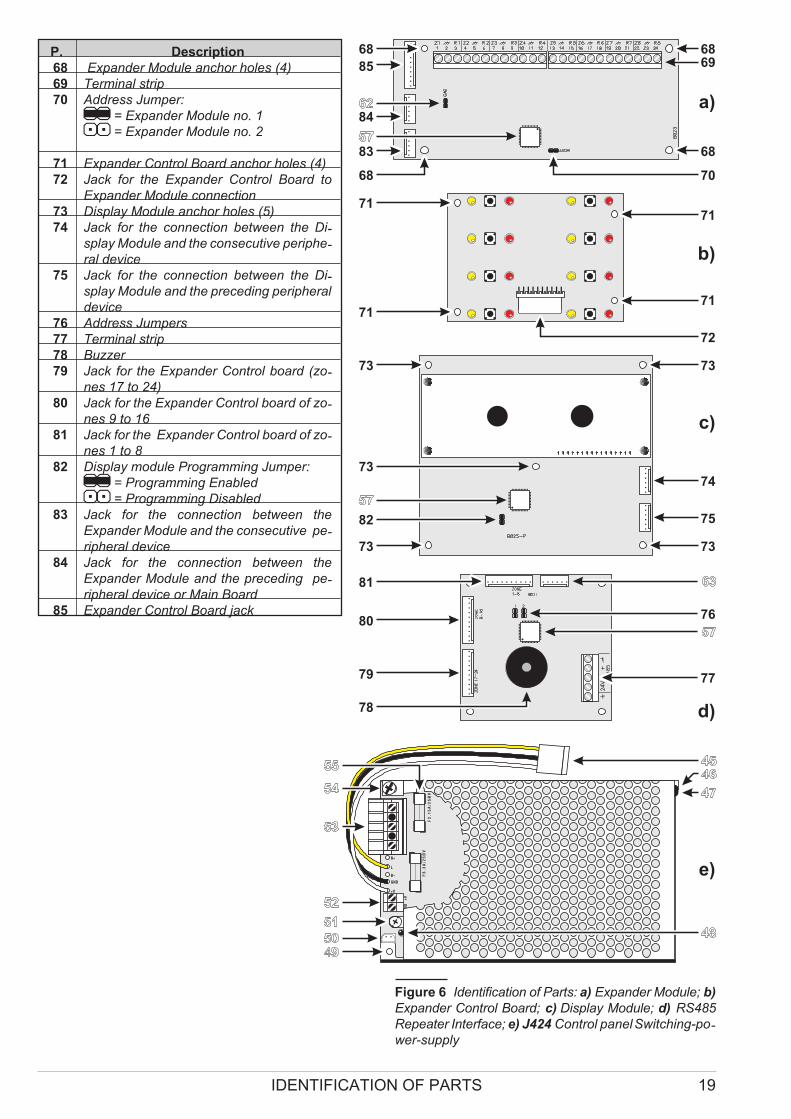
P. Description
68 Expander Module anchor holes (4)
69 Terminal strip
70 Address Jumper:
// = Expander Module no. 1
oo = Expander Module no. 2
71 Expander Control Board anchor holes (4)
72 Jack for the Expander Control Board to
Expander Module connection
73 Display Module anchor holes (5)
74 Jack for the connection between the Di-splay Module and the consecutive periphe-ral device
75 Jack for the connection between the Di-splay Module and the preceding peripheral
device
76 Address Jumpers
77 Terminal strip
78 Buzzer
79 Jack for the Expander Control board (zo-nes 17 to 24)
80 Jack for the Expander Control board of zo-nes 9 to 16
81 Jack for the Expander Control board of zo-nes 1 to 8
82 Display module Programming Jumper:
// = Programming Enabled
oo = Programming Disabled
83 Jack for the connection between the
Expander Module and the consecutive pe-ripheral device
84 Jack for the connection between the
Expander Module and the preceding pe-ripheral device or Main Board
85 Expander Control Board jack
IDENTIFICATION OF PARTS 19
AC
/NFG
+V
GN
D
B+
L
B–
GND
+V
AC
/L
F3
.1
5A
/2
5Ø
V
F6
.3
A/2
5Ø
V
68 68
85
84
83
68
69
68
70
71
72
7171
71
73
74
75
73
73
73
82
73
a)
b)
c)
81
80
79
78
76
77
d)
e)
Figure 6 Identification of Parts: a) Expander Module; b)
Expander Control Board; c) Display Module; d) RS485
Repeater Interface; e) J424 Control panelSwitching-po-wer-supply

Description of the Control keys
The Control panel keys can be activated by Keyswitch
and PIN Code Users ONLY (Access level 2 — Key tur-
ned in keyswitch or PIN Code entered — refer to
“Access to Signalling and Commands”), unless otherwi-
se stated.
LED ON Fault
Electro-
valve
Glowing indicates “Extinguishment” in course Fast blinking indicates power supply failure to
the electrovalve connected to output EV, or that
the latter is either open or shorted
Pre
Ext.
Glowing indicates “Pre-Extinguishment” in course.
Fast blinking indicates that alarms have been
generated in some of the zones programmed for
activation of the Extinguishment Module.
Fast blinking indicates that terminals [+] and [–]
of output PR are either disconnected or shorted
Manual
Ext.
Glowing indicates that input EM has been activa-ted
Fast blinking indicates that terminals [+] and [–]
of input EM are either disconnected or shorted
Disab.
Ext.
Glowing indicates that input IE has been activa-ted
Fast blinking indicates that terminals [+] and [–]
of input IE are either disconnected or shorted
Pres.
Switch
Glowing indicates that the input PS has been ac-tivated, due to low extinguishant gas pressure
Fast blinking indicates that terminals [+] and [–]
of input PS are either disconnected or shorted
Logic Unit — Fastblinking indicates “blocked”ExtinguishmentBoard
Disable
Extinguish.
Glowing indicates “Extinguishment” is inhibited
Disable
Manual
Extinguish.
Glowing indicates “Manual Extinguishment” is
inhibited
Disable
Automatic
Extinguish.
Glowing indicates that “Automatic Extingui-shment” is inhibited
Table 1 (continued from page 9) … Description of the LEDs
Key DESCRIPTION
Silence This key can be used to restore the Silenceable outputs to standby status (terminals [NAC1], [NAC2],
[DL], [TROUBLE], [ALARM — if programmed] and [Rn — if programmed]. Silence status will be held
until the Silence key is pressed again or, if the Control panel is operating in Night Mode, until the
Night mode Silence time expires or until a new Alarm/Trouble condition is detected.
Ack./ Evac. This key can be used to refresh the “Pre-Alarm Time” or trigger an Alarm:
For all persons on the premises: If this key is pressed for over 5 seconds during “Pre-Alarm Time”,
the system will generate an alarm.
For Key and PIN Code Users ONLY (Access level 2): If this key is pressed during “Pre-Alarm
Time”, the remaining Pre-Alarm Time will be refresh with the programmed Investigation Time. If it is
pressed for over 5 seconds during “Pre-Alarm Time”, the system will generate an alarm.
Reset This key can be used to reset the Fire detectors and restore all outputs to standby status (Supervi-sed/Silenceable outputs, NON-Supervised/Non-Silenceable outputs and Alarm zone outputs).
Disab. Buzzer This key can be used to disable the buzzer. The buzzer will be re-enable if any kind of event occurs.
Night Mode This key can be used to switch from Day to Night Mode.
Disab./Fault
NAC
This key can be used to disable the Bypassable Fire alarm outputs (terminals [NAC1] and [NAC2]).
Disab./Fault
Telecom
This key can be used to disable the Telephone device output (terminal [DL])
Test This key can be used to test the zones, buzzer and LEDs . If this key is pressed (when the Control pa-nel is functioning as intended), all the LEDs will Glow and the buzzer will emit a continuous beep.
For Access level 2 Users ONLY: If this key is pressed with the Disable key of a zone (z1, z2, .., z24)
it will activate the respective zone test phase.
z1 … z24 These keys can be used to disable their respective zones. Disabled zones will provide visual signal-ling of fire and fault conditions but will not activate any outputs or store events in Memory.
Disable
Extinguish.
This key can be used to disable the “Extinguishment” function.
Disable
Manual
Extinguish.
This key can be used to disable the “Manual Extinguishment” function. If this function is disabled, it
will not be possible to activate Extinguishment function via the EM input.
Disable
Automatic
Extinguish.
This button can be used to disable the “Automatic Extinguishment” function. If this function is disa-bled, the zones will not be unable to activate Extinguishment”.
Table 2 Description of keys

INSTALLING THE CONTROL PANEL
! Installation of this system must be carried out
strictly in accordance with the instructions in
this section, and in compliance with the local
safety regulations in force.
� Choose suitable mounting locations for the Control
panel, detectors, fire warning and fire control devices.
� Lay the cables between the Control panel and the
system peripherals.
� If necessary, install any accessory modules (Expan-ders, etc.).
� Mount the Control panel to the wall.
� Carry out the necessary connections, leaving the po-wer-supply connection until last.
� Program the Control panel in accordance with the in-structions in the “PROGRAMMING” section.
� Test the entire system (Control panel, detectors, fire
warning and fire control devices).
� Accessory Modules (Expanders Modules, Extin-
guishment Modules, etc.) should be installed befo-
re mounting the Control panel to the wall.
Installing accessory boards
! Ensure that the Control panel power supply
(Mains and Batteries) has been disconnected
before installing any accessory the Modules.
� Accessory Modules must be enrolled.
� Installing Extinguishment Modules
J408 The J408 can house 1 Extinguishment Module, posi-tioned as shown on page 14 (see part no. 28). To install the
Extinguishment Module, work through the following steps.
1. Remove the screws 4 and open the Control panel.
2. Hold the unit with the component side facing you.
Insert the Extinguishment Module under the clips 86
on the top part of the housing (see Figure 7a), then
snap it gently into place. Ensure that it is resting
properly on the plastic support pins 87 (see Figu-re 7a) and that it is held firmly in position by the clips
88 (as per Figure 7b).
3. Ensure that the Jumpers, marked “1” and “2” on the
PCB (43 and 59 in the “Parts Description Table”)
are inserted (Extinguishment Module no. 1).
4. Using the Flat cable (27), connect the Extingui-shment Module to the Main Board, via the jacks (58
and 63 respectively).
5. Place the label provided with the Extinguishment
Module next to the data label that is already present
on one of the Control panel’s sides.
� The polarity of the Flat cable connectors must be
observed.
J424 The J424 Control panel can house 2 Extingui-shment Modules (28 and 31 in the Figure on page 12).
Install the Extinguishment Module, as follows.
1. Remove the screws (4) and open the Control panel.
2. Fit the spacers (91) onto the plastic pins (90).
3. Using the nuts (93), secure the Extinguishment Mo-
dule in position.
INSTALLING THE CONTROL PANEL 21
86
a)
b)
87 86 86 88
88 89 89 89
Figure 7 J408: Installing the Extinguishment Module
90
a) b)
91 90 91
90 91 90 91
92 92
92 92
Figure 8 J424: Installing the Extinguishment Module

4. Using the Jumper (43), marked “1” on the PCB, set
up the Extinguishment Module address:
Jumper (43) IN = Extinguishment Module nr. 1;
Jumper (43) OUT = Extinguishment Module nr. 2.
� The Jumper (59), marked “2” on the PCB, MUST
BE INSERTED.
5. Using the Flat cables connect the Extinguishment
Modules as follows:
if you are installing ONE Extinguishment Module
— connect it to the Main Board, via the jacks (58
and 63 respectively), as per Fig. 9a;
if you are installing TWO Extinguishment Modules
— connect Extinguishment Module nr. 1 to Extingui-shment Module nr. 2, via the jacks (56) then, connect
Extinguishment Module nr. 1 to the Main Board, via the
jacks (58 and 63 respectively), as per Fig. 9b.
6. Place the label provided with the Extinguishment
Module next to the data label that is already present
on one of the Control panel’s sides.
� The polarity of the Flat cable connectors must be
observed.
� Installing Expander Module Kit (for J424 ONLY)
This Expander Module Kit comprises an 8 zone Expan-der Module and the Expander Control board. The
Expander Module contains most of the electronic circu-itry and electrical terminals whereas the Expander Con-trol board provides the LEDs and control keys for
Expander Module zones.
Install Expander Modules as follows:
� if you are installing ONE Expander Module Kit,
mount the Expander Module (21) and the Expander
Control board (10), as per Figure 11a;
� if you are installing TWO Expander Module Kits,
mount Expander Module nr. 1 (21) and the Expander
Control board (10) to the backplate then mount
Expander Module nr. 2 (25) and the Expander Con-trol board (7), as per Figure 11b.
�If you are installing ONE Expander Module Kit only,
the location will be different to that shown in the
diagram.
22 Conventional Fire Panels J424/J408
13
9
28
31
13
9
28
a)
b)
27 6358
27 6356 29 56
Figure 9 Connecting ONE Extinguishment Module (a)
or TWO Extinguishment Modules (b) to a J424 Control
panel: 9) Main Control Board; 13) Main Board; 27) and
29) Flat cable for the connection of the Extinguishment
Modules; 28) Extinguishment Module nr. 1; 31) Extin-guishment Module nr. 2; 56) Jack for the connection to
the consecutive Extinguishment Module; 58) Jack for
the connection to the Main Board; 63) Jack for the con-nection of Extinguishment Module nr. 1.
93
93
95 96 97 98 99 98 99 100 100
93 98 99 98 99 100 100
a) b) c) d) e)94
94 94
Figure 10 Installing an Expander Module Kit: 93) Reverse locking supports; 94) Expander Module anchor holes;
95) Long plastic spacer; 96) Expander Module placement screw; 97) Expander Module nut; 98) Expander Control Bo-ard screws; 99) Short plastic spacer; 100) Expander Control Board nut.
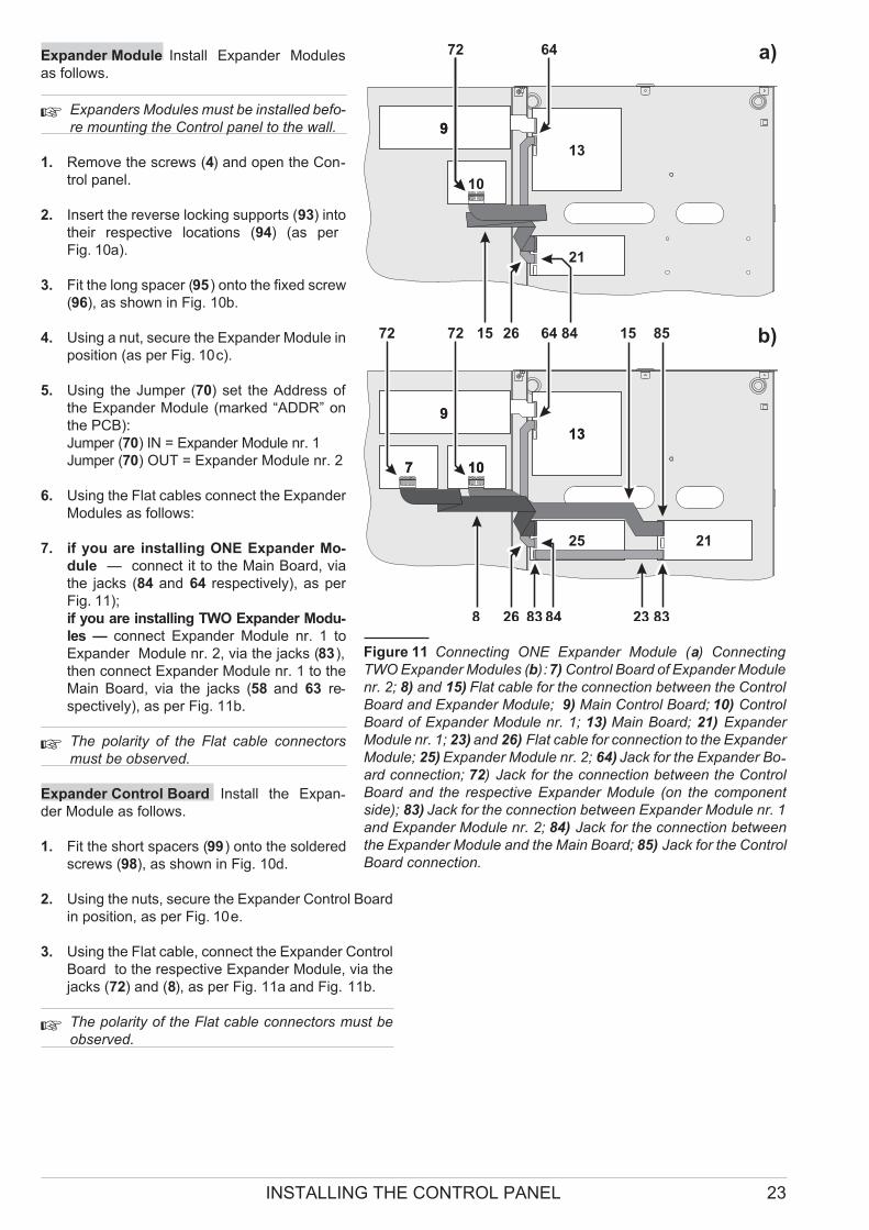
Expander Module Install Expander Modules
as follows.
� Expanders Modules must be installed befo-
re mounting the Control panel to the wall.
1. Remove the screws (4) and open the Con-trol panel.
2. Insert the reverse locking supports (93) into
their respective locations (94) (as per
Fig. 10a).
3. Fit the long spacer (95) onto the fixed screw
(96), as shown in Fig. 10b.
4. Using a nut, secure the Expander Module in
position (as per Fig. 10c).
5. Using the Jumper (70) set the Address of
the Expander Module (marked “ADDR” on
the PCB):
Jumper (70) IN = Expander Module nr. 1
Jumper (70) OUT = Expander Module nr. 2
6. Using the Flat cables connect the Expander
Modules as follows:
7. if you are installing ONE Expander Mo-
dule — connect it to the Main Board, via
the jacks (84 and 64 respectively), as per
Fig. 11);
if you are installing TWO Expander Modu-
les — connect Expander Module nr. 1 to
Expander Module nr. 2, via the jacks (83),
then connect Expander Module nr. 1 to the
Main Board, via the jacks (58 and 63 re-spectively), as per Fig. 11b.
� The polarity of the Flat cable connectors
must be observed.
Expander Control Board Install the Expan-der Module as follows.
1. Fit the short spacers (99) onto the soldered
screws (98), as shown in Fig. 10d.
2. Using the nuts, secure the Expander Control Board
in position, as per Fig. 10e.
3. Using the Flat cable, connect the Expander Control
Board to the respective Expander Module, via the
jacks (72) and (8), as per Fig. 11a and Fig. 11b.
�The polarity of the Flat cable connectors must be
observed.
INSTALLING THE CONTROL PANEL 23
99
21
21
25
101077
13
1313
9
72 72 64 15 85
8 26 83 84 23 83
99
10
72
842615 b)
a)64
Figure 11 Connecting ONE Expander Module (a) Connecting
TWO Expander Modules (b):7) Control Board of Expander Module
nr. 2; 8) and 15) Flat cable for the connection between the Control
Board and Expander Module; 9) Main Control Board; 10) Control
Board of Expander Module nr. 1; 13) Main Board; 21) Expander
Module nr. 1; 23) and 26) Flat cable for connection to the Expander
Module; 25) Expander Module nr. 2; 64) Jack for the Expander Bo-ard connection; 72) Jack for the connection between the Control
Board and the respective Expander Module (on the component
side); 83) Jack for the connection between Expander Module nr. 1
and Expander Module nr. 2; 84) Jack for the connection between
the Expander Module and the Main Board; 85) Jack for the Control
Board connection.

� Display Module (for J424 and J400-REP ONLY)
The J424 Control panel and the J400-REP Repeater
both accept Display Modules (see 6 pages 12 and 16).
� This instructions in the following section refer to the
connection of an LCD Module to a J424 Control pa-
nel, the connection procedure for the J400-REP
Repeater is similar.
1. Remove the screws (4) and open the Control panel.
2. Remove the nuts (101), as per Fig. 12a.
3. Remove the protective film (108) from the glass pla-te (102), as per Fig. 12b.
4. Screw the brass tapped spacers (104) onto the fixed
screws (103) and fit the plastic spacers (106) to the
fixed screws (107), as per Fig. 12c.
5. Using the previously removed nuts (101), and tho-se supplied with the display Module (105), secure
the Display Module in position, as per Fig. 12d.
6. Using the Flat cable, connect the Display Module
as follows:
J424: if NO Extinguishment Modules are installed
— connect the Display Module directly to the Main
Board via the jacks (75 and 63 respectively), as per
Fig. 13a;
J424: if ONE Extinguishment Modules is instal-
led — connect the Display Module to the Extingui-shment Module via the jacks (75 and 56
respectively), as per Fig. 13b;
424: if TWO Extinguishment Modules are instal-
led — connect the Display Module to Extingui-shment Module nr. 2 via the jacks (75 and 58
respectively), as per Fig. 13c;
J400-REP: connect the Display Module to the RS485
Interface via the jacks (75 and 63 respectively).
� The polarity of the Flat cable connectors must be
observed.
7. Set the Display Module Address, as described in
the “Display Module” section under “PRO-GRAMMING FROM THE CONTROL PANEL”
101
107 103 107106 106104
101
101
102
108
103104 104
103
105 105
a) b) c) d)
Figure 12 Installing the Display Module: 101) and 105) nuts; 102) glass plate; 103) and 107) soldered screws;
104) Brass tapped spacers; 106) Plastic spacers; 108) Protective film.
6375 30
613
9
5675
613
9
28
31
613
9
28
30
755830
a)
b)
c)
Figure 13 Connecting an LCD Module to a Control pa-nel: a) without Extinguishment Modules; b) with ONE
Extinguishment Module; c) with TWO Extinguishment
Modules ;6) Display Module; 9) Main Control Board; 13)
Main Board; 28) Extinguishment Module nr. 1; 30) Flat
cable for the Display Module connection; 31) Extingui-shment Module nr. 2.
Installing Repeaters
� The Display Module (if used) must be installed be-
fore the Repeaters.
Repeaters can be wall mounted, or flush mounted to an
ave® BL08 outlet box (or similar).
Work carefully through the following steps.
1. Lay the connection cables (refer to “Connecting
Repeaters”).
2. Remove the screws (4) and open the Control panel.
3. Take out the bag 22 containing the Repeater panel
Keys (Access Level 2).
4. If necessary, install the Display Module as descri-bed in the “Display Module” section.
5. If you are flush mounting the Repeater, go to step
7. If you are wall mounting the Repeater, drill the
anchor screw holes 33.
6. Pull the wires through the wire entry 34, then, using
the anchor screws, secure the Repeater to the wall.
7. Complete the connections to the terminal board 77
of the RS485 Interface (part nr. 35), as described in
the “Connecting Repeaters” section.
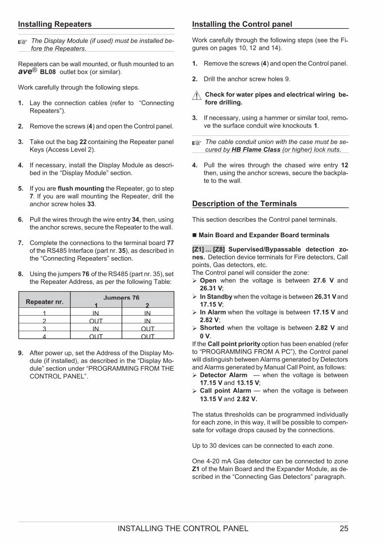
8. Using the jumpers 76 of the RS485 (part nr. 35), set
the Repeater Address, as per the following Table:
Repeater nr.Jumpers 76
1 2
1 IN IN
2 OUT IN
3 IN OUT
4 OUT OUT
9. After power up, set the Address of the Display Mo-
dule (if installed), as described in the “Display Mo-
dule” section under “PROGRAMMING FROM THE
CONTROL PANEL”.
Installing the Control panel
Work carefully through the following steps (see the Fi-gures on pages 10, 12 and 14).
1. Remove the screws (4) and open the Control panel.
2. Drill the anchor screw holes 9.
! Check for water pipes and electrical wiring be-fore drilling.
3. If necessary, using a hammer or similar tool, remo-ve the surface conduit wire knockouts 1.
� The cable conduit union with the case must be se-
cured by HB Flame Class (or higher) lock nuts.
4. Pull the wires through the chased wire entry 12
then, using the anchor screws, secure the backpla-te to the wall.
Description of the Terminals
This section describes the Control panel terminals.
� Main Board and Expander Board terminals
[Z1] ... [Z8] Supervised/Bypassable detection zo-
nes. Detection device terminals for Fire detectors, Call
points, Gas detectors, etc.
The Control panel will consider the zone:
� Open when the voltage is between 27.6 V and
26.31 V;
� In Standby when the voltage is between 26.31 Vand
17.15 V;
� In Alarm when the voltage is between 17.15 V and
2.82 V;
� Shorted when the voltage is between 2.82 V and
0 V.
If the Call point priority option has been enabled (refer
to “PROGRAMMING FROM A PC”), the Control panel
will distinguish between Alarms generated by Detectors
and Alarms generated by Manual Call Point, as follows:
� Detector Alarm — when the voltage is between
17.15 V and 13.15 V;
� Call point Alarm — when the voltage is between
13.15 V and 2.82 V.
The status thresholds can be programmed individually
for each zone, in this way, it will be possible to compen-
sate for voltage drops caused by the connections.
Up to 30 devices can be connected to each zone.
One 4-20 mA Gas detector can be connected to zone
Z1 of the Main Board and the Expander Module, as de-
scribed in the “Connecting Gas Detectors” paragraph.
INSTALLING THE CONTROL PANEL 25
� EN 54-2 certification applies ONLY when: no more
than 30 devices are connected to each zone; no
more than 3 Gas detectors are connected to the
Control panel; no more than 512 devices IN ALL
are connected to the Control panel.
If a zone triggers an Automatic Alarm during Day
Mode, the Control panel will initialize the Pre-alarm
phase.
If a zone triggers an Automatic Alarm during Night
Mode, the Control panel will generate an instant Alarm.
If a zone triggers a Manual Alarm — whether in Day or
Night Mode, the Control panel will generate an instant
Alarm.
If a zone Shorts or Opens , the Control panel will gene-rate a Trouble warning.
Each Reset operation will interrupt the power supply to
all zones for the programmed Detector Reset Time.
[M] Detector negative
[R1] ... [R8] Silenceable/Repeat Outputs
Each zone provides a Repeat Output for selective inter-vention purposes (to close Fire doors, to limit signalling
to the Zone concerned, etc.).
� DO NOT connect EN54 “E”, “J” or “C” rated devices
(visual, audible or telephone signalling devices) to
Outputs R1, R2, …, R8.
Repeat Outputs are Normally Open.
Operating principles:
If the Pre-Alarm on R Output option is DISABLED, the
Repeat Output of the zone in Alarm status will pull down
to 0 V (negative) when the Control panel triggers Alarm
status.
If the Pre-Alarm on R Output option is ENABLED, the
Repeat Output of the zone in Alarm status will pull down
to 0 V (negative) when the Control panel triggers
Pre-Alarm status.
All the Repeat Outputs will restore to standby when the
Control panel Resets.
�If the Gas Detector option ENABLED, the Repeat
Output of the zone will restore to standby when the
Voltage on the zone terminal concerned drops be-low the Pre-Alarm threshold, that is, as long as the
Alarm threshold value has not been exceeded in
the meantime.
If the Non-Silenceable R Output option is DISABLED,
it will be possible to Silence (force to standby) the Repe-
at Output of the zone concerned.
Repeat Outputs will hold standby status for the pro-
grammed Silence Time.
If Alarm conditions are present when the Silence Time
expires, the Repeat Output will re-activate.
Up to 0.1 A can circulate on each Repeat Output.
� Outputs R1, R2, ..., R8 accept devices that operate
within SELV limits ONLY.
�Main Board Terminals
[24V] [M] Auxiliary Power Supply
Power supply for devices that function at 24 V, protec-ted by a resettable fuse, has battery backup.
Operating principles
� Positive pull-up to 27.6 V on the [24V] terminal;
� Negative pull-down to 0 V on the [M] terminal.
If the current draw on the [24V] terminal exceeds 1 A,
the system will interrupt the power supply to the termi-nal and signal Fault on the 24V/24R LED (fast blinking).
The system will restore power to the terminal when the
current draws drops below 1 A.
[24R] [M] Resettable Auxiliary Power Supply
Resettable Power supply for devices that function at
24 V, protected by a resettable fuse, has battery bac-kup.
Operating principles
� Positive pull-up to 27.6 V on the [24R] terminal;
� Negative pull-down to 0 V on the [M] terminal.
If the current draw on the [24R] terminal exceeds 1 A,
the system will interrupt power to the terminal, and
will signal Fault on the 24V/24R LED (fast blinking).
The system will restore power to the terminal when
the current draws drops below 1 A.
The system will interrupt power from terminal [24R]
during Reset, therefore, this power source can be
used to power devices that reset when the power
supply is interrupted.
OC Programmable Auxiliary Output
This Output can be programmed to signal one or more
of the following events:
� Alarm
� Pre-alarm
� Fault
� Reset
� Disable
� Test
� Double Knock
� DO NOT connect EN54 “E”, “J” or “C” rated devices
(visual, audible or telephone signalling devices) to
the OC output.
The OC Output (Open-Collector) is Normally Open.
Operating principles:
This Output will activate when one of its associated
events occurs, and will restore when the event ends.
Up to 1 A can circulate on the OC Output.
�The OC Output accepts devices that operate within
SELV limits ONLY.
26 Conventional Fire Panels J424/J408
[DL] Supervised/Bypassable Dialler Output
This Output is for Dialler activation.
Operating principles
This Normally-Open Output (open-collector) will:
� pull down to 0 V (negative) when the Alarm Signal-
ling Delay expires (refer to “DL Output” under “Out-puts” in the “PROGRAMMING FROM A PC” section);
� restore to standby when the Control panel Resets.
Activation of the DL Output will be indicated by Glowing
on the Telecom LED.
Short-circuit or power supply interruption on the DL
Output will be indicated by fast blinking on the Di-sab./Fault Telecom LED.
The DL Output can be disabled by means of the Disab./Fa-ult Telecom key. Disablement of the DL Output will be
indicated by Glowing on the Disab./Fault Telecom LED.
If the DL Output is disabled, it will be unable to activate
in the event of alarm.
Up to 0.1 A can circulate on the DL Output.
�The DL Output accepts devices that operate within
SELV limits ONLY.
PL Power Loss Output
This Output is for Power loss signalling.
Operating principles
This Normally-Open Output will:
� pull down to 0 V (negative) in the event of total power
failure (Mains and battery power supply);
� restore to standby when the power supply conditions
return to normal.
Up to 1 A can circulate on the PL Output.
�The PL Output accepts devices that operate within
SELV limits ONLY.
ALARM Silenceable Alarm Output
This Voltage free contact can be used for the connec-
tion of devices which cannot be connected directly to
NAC1 or NAC2.
Operating principles:
� in Standby status, terminal [C] closes to terminal [NC];
� in the event of an Alarm, terminal [C] will close to ter-
minal [NO], as per programming (refer to “ALARM
Output” under “Outputs” in the “PROGRAMMING
FROM A PC” section).
The ALARM Output will restore to standby when the
Control panel resets.
� DO NOT connect EN54 “E”, “J” or “C” rated devices
(visual, audible or telephone signalling devices) to
the ALARM Output.
If the NON-Silenceable option of the ALARM Output has
been DISABLED (refer to “ALARM Output” under “Out-puts” in the “PROGRAMMING FROM A PC” section), it
will be possible to Silence (force to standby) this Output.
The ALARM Output will hold standby status for the pro-grammed Silence Time.
If Alarm conditions are present when the Silence Time
expires, the ALARM Output will re-activate.
Up to 5 A can circulate on the ALARM Output.
� The ALARM Output accepts devices that operate
within SELV limits ONLY.
TROUBLE Silenceable Trouble Output
This Output is for Trouble signalling.
Operating principles
� in Standby status, terminal [C] closes to terminal [NC];
� in Trouble status, terminal [C] will close to terminal
[NO] (refer to “Trouble” in the “INTRODUCTION”).
� DO NOT connect EN54 “E”, “J” or “C” rated devices
(visual, audible or telephone signalling devices) to
the TROUBLE output.
Up to 5 A can circulate on the TROUBLE Output.
�The TROUBLE Output will activate when the power
supply to the Control panel fails (Mains and battery
power supply). The TROUBLE Output accepts devi-ces that operate within SELV limits ONLY.
NAC1 and NAC2 Supervised/Silenceable/Bypassa-
ble Alarm Outputs
These Outputs are for the Alarm signalling devices.
Operating principles:
� in Standby status, these Outputs will be INACTIVE
(read on for details);
� in Pre-Alarm status, these Outputs will ACTIVATE
(read on for details) and DE-ACTIVATE in accordan-
ce with the programmed Pre-Alarm Pattern (refer
to “NAC1” and “NAC2” under “Outputs” in the
“PROGRAMMING FROM A PC” section);
� in Alarm status, these Outputs will ACTIVATE and
DE-ACTIVATE in accordance with the programmed
Alarm Pattern (refer to “NAC1” and “NAC2” under “Out-puts” in the “PROGRAMMING FROM A PC” section).
Output INACTIVE: negative pull-down to 0 V on [+] termi-nal; positive pull-up to 27.6 V on the [–] terminal.
Output ACTIVE: positive pull-up to 27.6 V on the [+] ter-minal; negative pull-down to 0 V on the [–] terminal.
� NAC1 and NAC2 will restore to standby when the
Control panel Resets.
If the “Bistable” option is enabled (refer to “Outputs”
in the “PROGRAMMING FROM A PC” section), the
NAC2 Output will return to standby when all zones
return to standby.
� NAC1 and NAC2 can be Silenced (forced to standby).
The NAC Outputs will hold standby status for the pro-grammed Silence Time. If Alarm conditions are pre-sent when the programmed Silence Time expires,
they will re-activate.
Short-circuit or power supply interruption on NAC1 or
NAC2 will be indicated by fast blinking on the Di-sab./Fault NAC LED.
NAC1 and NAC2 can be disabled by means of the Di-sab./Fault NAC key.
Disablement of these Outputs will be indicated by
Glowing on the Disab./Fault NAC LED.
If NAC1 and NAC2 are disabled, they will be unable to
activate in the event of alarm.
Up to 1 A can circulate on NAC1 and NAC2.
INSTALLING THE CONTROL PANEL 27
� NAC1 and NAC2 accept devices that operate wit-
hin SELV limits ONLY.
� Extinguishment Module Terminals
EM Supervised/Bypassable Manual Extingui-
shment Input
This Input is for manual activation of the Fire Extingui-shment systems.
Standby status of this Input can be either Normally
Open (at default) or Normally Closed (refer to “Manual
Extinguishment Input” under “Enrolling: Extinguishment
Modules” in the “PROGRAMMING FROM PC”)
Operating principles:
� the Control panel will consider the EM Input OPEN
when a 3.900 ohm resistance is applied to its [+] and
[–] terminals;
� the Control panel will consider the EM Input CLOSED
when one or more (up to 10) 680 ohm resistor is/are
applied in parallel to the 3.900 ohm resistance.
The EM Input will activate when inverse conditions to its
standby conditions occur.
Activation of the EM Input will start the Pre-Extingui-shment Time.
Activation of the EM Input will be indicated by Glowing
on the ON Manual Ext. LED.
Short-circuit or power supply interruption on the EM Input will
be indicated by fast blinking on the Fault Manual Ext.LED.
The EM input can be disabled by means of the Disable
Manual Extinguish. key.
Disablement of this Input will be indicated by Glowing
on the Disable Manual Extinguish. LED.
IE Supervised Inhibit Extinguishment Input
This Input is for the inhibition of Fire Extinguishment
systems.
The standby status of this Input can be either Normally
Open (at default) or Normally Closed (refer to “Disable
Extinguishment Input” under “Enrolling: Extinguishment
Modules” in the “PROGRAMMING FROM A PC”).
Operating principles:
� the Control panel will consider the IE Input OPEN
when a 3.900 ohm resistor is applied between its [+]
and [–] terminals;
� the Control panel will consider the IE Input CLOSED
when one or more (up to 10) 680 ohm resistor is/are
applied in parallel to the 3.900 ohm resistor.
The IE Input will activate when the inverse conditions to
its programmed standby conditions occur.
If the IE Input is active when Extinguishment conditions oc-cur, the Control panel will activate the PR Output (Pre-Extin-guishment) and WILL START the Pre-Extinguishment Time.
If the IE Input activates during the Pre-Extinguishment
phase, the Control panel WILL NOT STOP the
Pre-Extinguishment Time.
In both cases, when the time has elapsed, no extingui-shment will occur unless the IE Input is restored to
stand-by. If the IE Input is activated during the Extingui-shment phase, this will have no effect.
Activation of the IE Input will be indicated by Glowing on the
ON Disab. Ext. LED.
Short-circuit or power supply interruption on the IE Input will
be indicated by fast blinking on the Fault Disab. Ext.LED.
PS Supervised Pressure Switch Input
This Input is for the Pressure Switch connection.
Standby status of this Input can be either Normally
Open (at default) or Normally Closed (refer to “Pressu-re Switch Input” under “Enrolling: Extinguishment Mo-dules” in the “PROGRAMMING FROM A PC”).
� the Control panel will consider the PS Input OPEN
when a 3.900 ohm resistor is applied across its [+]
and [–] terminals;
� the Control panel will consider the PS Input CLOSED
when one or more (up to 10) 680 ohm resistor is/are
applied in parallel to the 3.900 ohm resistor.
The PS Input will activate when the inverse conditions
to its programmed standby conditions occur.
Activation of the PS Input will be indicated by Glowing
on the ON Pres. Switch LED. Short-circuit or power
supply interruption on the PS Input will be indicated by
fast blinking on the Fault Pres. Switch LED.
Short-circuit or power supply interruption on the PS
Input will be indicated by fast blinking on the Fault Pres.
Switch LED.
EV Supervised Electrovalve Output
This Output is for the Electrovalve connection.
Operating principles:
� in Standby status, the EV terminals will be OPEN;
� during the Extinguishment phase, the EV terminals
will be CLOSED.
Activation of the EV Output will be indicated by Glowing
on the ON Electrovalve LED. Short-circuit or power
supply interruption on the EV Output will be indicated by
fast blinking on the Fault Electrovalve LED.
Up to 5 A can circulate on the EV Output.
� This Output is not enabled if there is a fault with the
IE Input and/or the PR Output.
24P Power Boost Input
This Input is for the Power boost required by the devi-ces connected to Outputs PR and AE.
Wiring instructions:
Connect the [+] and [–] terminals of this Input to the [+]
and [–] terminals 47 of the Switching Power Supply.
PR Supervised/Silenceable Pre-Extinguishment
Output
This Output is for Pre-Extinguishment signalling.
Operating principles
� Standby status: negative pull-down to 0 V on the [+]
terminal; positive pull-up to 27.6 V on the [–] terminal.
� Pre-Extinguishment phase: positive pull-up to 27.6 V
on the [+] terminal; negative pull-down to 0 V on the
[–] terminal.
Activation of the PR Output will be indicated by Glowing
on the ON Pre Ext. LED.
Short-circuit or power supply interruption on the PR
Input will be indicated by fast blinking on the Fault Pre
Ext. LED.
Up to 1 A can circulate on the PR Output.
28 Conventional Fire Panels J424/J408

®
CONVENTIONAL
F I R E PA N E L S
424
408
ISO 140019191.BNT2
ISO 14001IT-52588
ISO 90019105.BNT1
ISO 9001IT-52587
OHSAS 180019192.BSEC
OHSAS 18001IT - 60983
USER’S INSTRUCTIONS
Standby status
During normal operating conditions (Standby status),
ONLY the green Mains LED and, if the Control panel is
operating in Night Mode, the Night Mode LED will be
On (glowing). The display will show the time and date
and “PANEL WORKING” message:
PANEL WORKING
17:30 13/10/2004
PRE-ALARM
If a fire detector goes into alarm during DAY Mode, the
Control panel will trigger the PRE-ALARM phase which
will be signalled by:
� the respective signalling devices;
� the Pre-al. LED (On);
� the Zone Alarm LEDs of the zones concerned
(glowing);
� an intermittent audible signal (0.5 second beep follo-wed by a 0.5 second pause);
� a message, similar to the following:
PREALARM
Warehouse
The bottom line on the display will show the label (e.g
Warehouse) of the zone that triggered the
PRE-ALARM.
During PRE-ALARM status, you can:
Use � or� to scroll the zones concerned.
If you do not press a button within 20 seconds, the di-splay will go back to the first zone that triggered the
PRE-ALARM.
Press Esc to access the Main menu.
If you do not press a button within 20 seconds, the di-splay will go back to the first zone that triggered the
PRE-ALARM.
PRE-ALARM status will last for the pre-set Time (refer
to the following paragraph for details).
�The Control panel will generate an instant Alarm
(refer to “Night Mode”), if alarm conditions are de-tected during Night Mode or, if an alarm is trigge-red from a Manual Call point — connected to a
zone with the Call point priority attribute (i.e. Call
point priority ENABLED).
ALARM
ALARM status will be signalled by:
� the respective signalling devices;
� the Alarm LED (On);
� the Zone Alarm LEDs of the zones concerned
(glowing);
� a fast intermittent audible signal (0.2 second beep
followed by a 0.2 second pause);
� an “ALARM” message, similar to the following:
ALARM ON ZONE 01
Warehouse
The top line of the display will show the number of the
zone that triggered the ALARM, and the bottom line will
show the zone label (e.g Warehouse).
During ALARM status, you can:
Use � or� to scroll the zones concerned.
If you do not press a button within 20 seconds, the di-splay will go back to the first zone that triggered the
ALARM.
Press Esc to view the Main menu.
If you do not press a button within 20 seconds, the di-splay will go back to first zone that triggered the
ALARM.
If zones restore to standby spontaneously, the ALARM
events will be stored in the Memory and signalled on the
respective Zone Alarm LEDs until you Reset the Con-trol panel.
� The Fire Alarm Outputs will not restore to standby
until you Reset the Control panel — even if an
Alarm ends spontaneously.
FAULT
FAULTS will be signalled by:
� the respective signalling devices;
� the Fault LED (On);
� the respective Fault LED (On) — refer to Table 1;
� a slow intermittent audible signal (1 second beep fol-lowed by a 1 second pause);
� a message on the display, similar to the following (re-fer to Table 1):
FAULT ON ZONE 01
Warehouse
If FAULT conditions are detected, you can:
Use � or� to scroll the Faults list.
If you do not press a button within 20 seconds, the di-splay will go back to the first fault that occurred.
Press Esc to view the Main Menu.
If you do not press a button within 20 seconds, the di-splay will go back to first FAULT that occurred.
If FAULTconditions clear spontaneously, the respective
events will be stored in the Memory, and will be signal-led by slow flashing on the respective LEDs.
�The Control panel will restore to standby when all
the FAULT conditions clear.
2 Conventional Fire Panels J424/J408
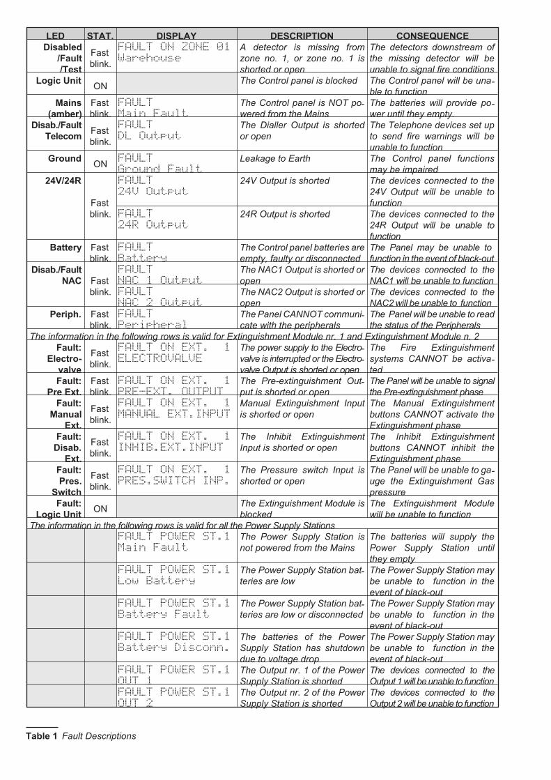
LED STAT. DISPLAY DESCRIPTION CONSEQUENCE
Disabled
/Fault
/Test
Fast
blink.
FAULT ON ZONE 01
Warehouse
A detector is missing from
zone no. 1, or zone no. 1 is
shorted or open
The detectors downstream of
the missing detector will be
unable to signal fire conditions
Logic UnitON
The Control panel is blocked The Control panel will be una-ble to function
Mains
(amber)
Fast
blink.
FAULT
Main Fault
The Control panel is NOT po-wered from the Mains
The batteries will provide po-wer until they empty.
Disab./Fault
TelecomFast
blink.
FAULT
DL Output
The Dialler Output is shorted
or open
The Telephone devices set up
to send fire warnings will be
unable to function
GroundON
FAULT
Ground Fault
Leakage to Earth The Control panel functions
may be impaired
24V/24R
Fast
blink.
FAULT
24V Output
24V Output is shorted The devices connected to the
24V Output will be unable to
function
FAULT
24R Output
24R Output is shorted The devices connected to the
24R Output will be unable to
function
Battery Fast
blink.
FAULT
Battery
The Control panel batteries are
empty, faulty or disconnected
The Panel may be unable to
function in the event of black-out
Disab./Fault
NAC Fast
blink.
FAULT
NAC 1 Output
The NAC1 Output is shorted or
open
The devices connected to the
NAC1 will be unable to function
FAULT
NAC 2 Output
The NAC2 Output is shorted or
open
The devices connected to the
NAC2 will be unable to function
Periph. Fast
blink.
FAULT
Peripheral
The Panel CANNOT communi-cate with the peripherals
The Panel will be unable to read
the status of the Peripherals
The information in the following rows is valid for Extinguishment Module nr. 1 and Extinguishment Module n. 2
Fault:
Electro-
valve
Fast
blink.
FAULT ON EXT. 1
ELECTROVALVE
The power supply to the Electro-valve is interrupted or the Electro-valve Output is shorted or open
The Fire Extinguishment
systems CANNOT be activa-ted
Fault:
Pre Ext.
Fast
blink.
FAULT ON EXT. 1
PRE-EXT. OUTPUT
The Pre-extinguishment Out-put is shorted or open
The Panel will be unable to signal
the Pre-extinguishment phase
Fault:
Manual
Ext.
Fast
blink.
FAULT ON EXT. 1
MANUAL EXT.INPUT
Manual Extinguishment Input
is shorted or open
The Manual Extinguishment
buttons CANNOT activate the
Extinguishment phase
Fault:
Disab.
Ext.
Fast
blink.
FAULT ON EXT. 1
INHIB.EXT.INPUT
The Inhibit Extinguishment
Input is shorted or open
The Inhibit Extinguishment
buttons CANNOT inhibit the
Extinguishment phase
Fault:
Pres.
Switch
Fast
blink.
FAULT ON EXT. 1
PRES.SWITCH INP.
The Pressure switch Input is
shorted or open
The Panel will be unable to ga-uge the Extinguishment Gas
pressure
Fault:
Logic UnitON
The Extinguishment Module is
blocked
The Extinguishment Module
will be unable to function
The information in the following rows is valid for all the Power Supply Stations
FAULT POWER ST.1
Main Fault
The Power Supply Station is
not powered from the Mains
The batteries will supply the
Power Supply Station until
they empty
FAULT POWER ST.1
Low Battery
The Power Supply Station bat-teries are low
The Power Supply Station may
be unable to function in the
event of black-out
FAULT POWER ST.1
Battery Fault
The Power Supply Station bat-teries are low or disconnected
The Power Supply Station may
be unable to function in the
event of black-out
FAULT POWER ST.1
Battery Disconn.
The batteries of the Power
Supply Station has shutdown
due to voltage drop
The Power Supply Station may
be unable to function in the
event of black-out
FAULT POWER ST.1
OUT 1
The Output nr. 1 of the Power
Supply Station is shorted
The devices connected to the
Output 1 will be unable to function
FAULT POWER ST.1
OUT 2
The Output nr. 2 of the Power
Supply Station is shorted
The devices connected to the
Output 2 will be unable to function
Table 1 Fault Descriptions
Access Level 2
Most of the functions provided by this Control panel are
available at Access Level 2. Therefore, only Key and
PIN Code Users can operate the system (PIN Code en-tered or Key turned in the Keyswitch).
Accessing Level 2 using a Key Insert the key into
the Keyswitch and turn it horizontally — access will be
indicated by a beep.
To exit Access Level 2: turn the key back and remove it
from the Keyswitch — the Control panel will hold
Access Level 2 for a further 20 seconds then will emit
two beeps to indicate the end of Access Level 2 status.
Accessing Level 2 using a PIN Code Type in your
PIN Code (1234 at Default): — access will be indicated
by a five beeps in rapid succession.
To exit Access Level 2: DO NOT press any button for
20 seconds: the end of Access Level 2 status will be in-dicated by two beeps in rapid succession.
Investigation Time (Ack./Evac. button)
The Ack./Evac. button will allow you to extend the pre-set Pre-alarm Time.
If you press Ack./Evac. button, the Pre-alarm Time will
be replenished with the pre-set Investigation Time.
� The Ack./Evac. button functions only during the
Pre-alarm phase (Pre-al. LED ON).
To activate the Investigation Time phase:
1. Enter the PIN Code or turn the key in the Keyswitch
(Access Level 2).
2. Press and hold the Ack./Evac. button for at least 5
seconds: the Ack./Evac. LED will go On to indica-te that the Investigation Time is running.
� You can request Investigation Time once only.
Evacuation (Ack./Evac. button)
You can also use the Ack./Evac. button to activate an
Evacuation Alarm.
To activate an ALARM when the Control panel is in
Pre-alarm status (Pre-al. LED ON), press and hold the
Ack./Evac. button AT LEAST 5 seconds.
To activate an Alarm when the Control panel is in
Standby status:
1. Enter the PIN Code or turn the key in the Keyswitch
(Access Level 2).
2. Press the Ack./Evac. button for at least 5 se-conds.
Silence
The Silence button will allow you to stop the signalling
devices. To Silence the signalling devices:
1. Enter the PIN Code or turn the key in the Keyswitch
(Access Level 2).
2. Press Silence.
Disable
If a detector is not working properly or is causing false
Alarms (signalled by fast blinking on the Disabled/Fa-ult/Test LED), you can disable it by pressing the respecti-ve zone button. You can disable signalling devices
(Bells, Sirens, Fire signs, etc.) by pressing the Di-sab./Fault NAC button, and disable the Dialler output
by pressing the Disab./Fault Telecom Button.
� Disabled devices will be unable to work in the
event of fire.
Reset
The Reset button will allow you to Reset the Control pa-
nel (stop the signalling devices, reset detectors and cle-
ar the memory). To Reset the Control panel:
1. Enter the PIN Code or turn the key in the Keyswitch
(Access Level 2).
2. Press Reset.
� To Reset the Control panel after an ALARM, first
press the Silence button.
Test
The Test button will allow you to check the working or-der of the Control panel LEDs and Buzzer.
Extinguishment Module
This Control panel is equipped with an Extinguishment
Module for fire extinguishment purposes (up to 2 Extin-guishment Modules can be connected to J424 Control
panels). These devices have been specially designed
to reduce unnecessary activation of Fire Extingui-shment appliances.
In the event of a Fire, the Extinguishment systems will
be activated when the pre-set Pre-Extinguishment
Time expires. These devices can also be activated from
manual call-points (ask your Installer for details).
Extinguishment systems may also be activated using
one of the buttons provided by the installer. In this case,
a different Pre-Extinguishment time may be set (refer to
the Programming from a PC section).
4 Conventional Fire Panels J424/J408
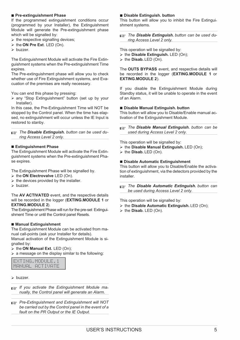
� Pre-extinguishment Phase
If the programmed extinguishment conditions occur
(programmed by your Installer), the Extinguishment
Module will generate the Pre-extinguishment phase
which will be signalled by:
� the respective signalling devices;
� the ON Pre Ext. LED (On).
� buzzer.
The Extinguishment Module will activate the Fire Extin-
guishment systems when the Pre-extinguishment Time
expires.
The Pre-extinguishment phase will allow you to check
whether use of Fire Extinguishment systems, and Eva-
cuation of the premises are really necessary.
You can end this phase by pressing:
� any “Stop Extinguishment” button (set up by your
Installer).
In this case, the Pre-Extinguishment Time will NOT be
stopped by the Control panel. When the time has elap-
sed, no extinguishment will occur unless the IE Input is
restored to stanby.
� The Disable Extinguish. button can be used du-
ring Access Level 2 only.
� Extinguishment Phase
The Extinguishment Module will activate the Fire Extin-guishment systems when the Pre-extinguishment Pha-se expires.
The Extinguishment Phase will be signalled by.
� the ON Electrovalve LED (On).
� the devices provided by the installer.
� buzzer.
The AV ACTIVATED event, and the respective details
will be recorded in the logger (EXTING.MODULE 1 or
EXTING.MODULE 2).
The Extinguishment Phase will run for the pre-set Extingui-shment Time or until the Control panel Resets.
� Manual Extinguishment
The Extinguishment Module can be activated from ma-nual call-points (ask your Installer for details).
Manual activation of the Extinguishment Module is si-gnalled by:
� the ON Manual Ext. LED (On);
� a message on the display similar to the following:
EXTING.MODULE.1
MANUAL ACTIVATE
� buzzer.
�If you activate the Extinguishment Module ma-nually, the Control panel will generate an Alarm.
� Pre-Extinguishment and Extinguishment will NOT
be carried out by the Control panel in the event of a
fault on the PR Output or the IE Output.
� Disable Extinguish. button
This button will allow you to inhibit the Fire Extingui-shment systems.
� The Disable Extinguish. button can be used du-
ring Access Level 2 only.
This operation will be signalled by:
� the Disable Extinguish. LED (On);
� the Disab. LED (On).
The OUTS BYPASS event, and respective details will
be recorded in the logger (EXTING.MODULE 1 or
EXTING.MODULE 2).
If you disable the Extinguishment Module during
Standby status, it will be unable to operate in the event
of an Alarm.
� Disable Manual Extinguish. button
This button will allow you to Disable/Enable manual ac-tivation of the Extinguishment Module.
�The Disable Manual Extinguish. button can be
used during Access Level 2 only.
This operation will be signalled by:
� the Disable Manual Extinguish. LED (On);
� the Disab. LED (On).
� Disable Automatic Extinguishment
This button will allow you to Disable/Enable the activa-tion of extinguishment, via the detectors provided by the
installer.
�The Disable Automatic Extinguish. button can
be used during Access Level 2 only.
This operation will be signalled by:
� the Disable Automatic Extinguish. LED (On);
� the Disab. LED (On).
USER’S INSTRUCTIONS 5
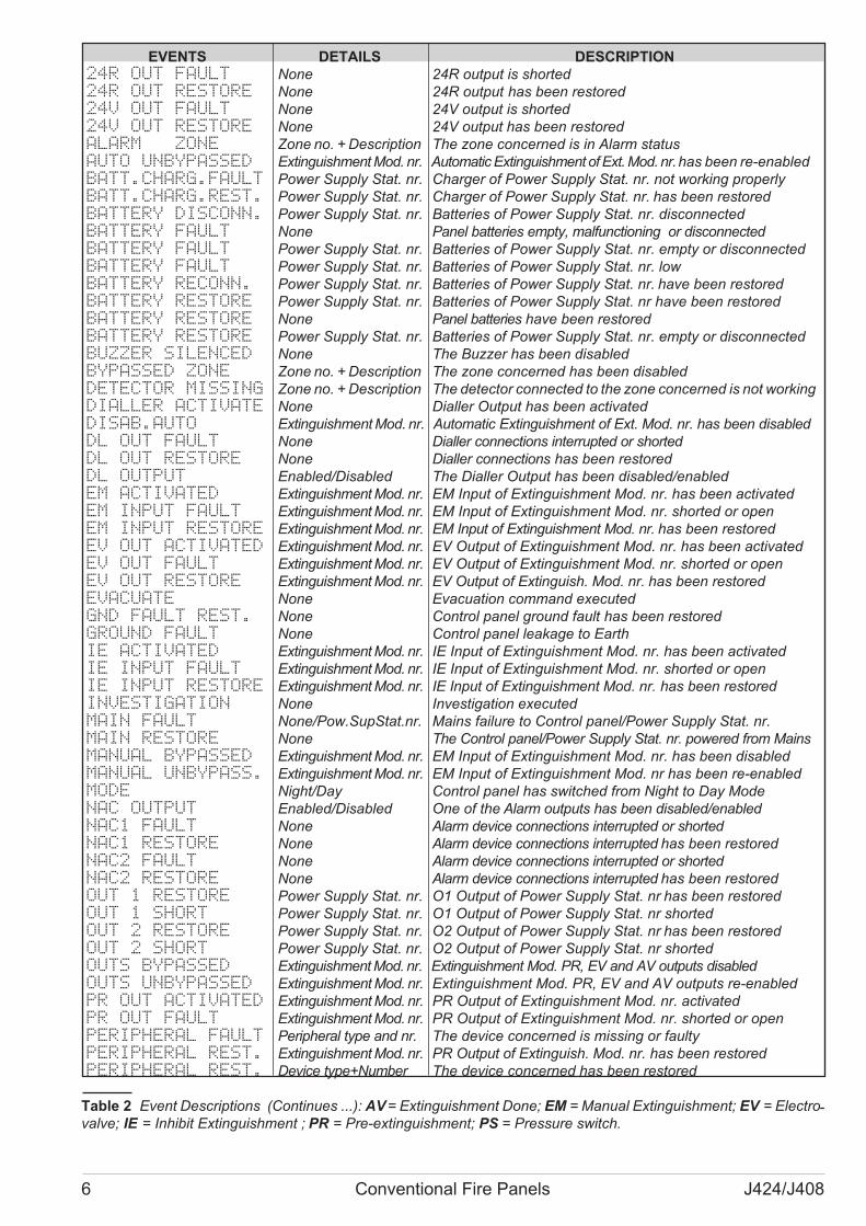
6 Conventional Fire Panels J424/J408
EVENTS DETAILS DESCRIPTION
24R OUT FAULT None 24R output is shorted
24R OUT RESTORE None 24R output has been restored
24V OUT FAULT None 24V output is shorted
24V OUT RESTORE None 24V output has been restored
ALARM ZONE Zone no. + Description The zone concerned is in Alarm status
AUTO UNBYPASSED Extinguishment Mod. nr. Automatic Extinguishment of Ext. Mod. nr.has been re-enabled
BATT.CHARG.FAULT Power Supply Stat. nr. Charger of Power Supply Stat. nr. not working properly
BATT.CHARG.REST. Power Supply Stat. nr. Charger of Power Supply Stat. nr. has been restored
BATTERY DISCONN. Power Supply Stat. nr. Batteries of Power Supply Stat. nr. disconnected
BATTERY FAULT None Panel batteries empty, malfunctioning or disconnected
BATTERY FAULT Power Supply Stat. nr. Batteries of Power Supply Stat. nr. empty or disconnected
BATTERY FAULT Power Supply Stat. nr. Batteries of Power Supply Stat. nr. low
BATTERY RECONN. Power Supply Stat. nr. Batteries of Power Supply Stat. nr. have been restored
BATTERY RESTORE Power Supply Stat. nr. Batteries of Power Supply Stat. nr have been restored
BATTERY RESTORE None Panel batteries have been restored
BATTERY RESTORE Power Supply Stat. nr. Batteries of Power Supply Stat. nr. empty or disconnected
BUZZER SILENCED None The Buzzer has been disabled
BYPASSED ZONE Zone no. + Description The zone concerned has been disabled
DETECTOR MISSING Zone no. + Description The detector connected to the zone concerned is not working
DIALLER ACTIVATE None Dialler Output has been activated
DISAB.AUTO Extinguishment Mod. nr. Automatic Extinguishment of Ext. Mod. nr. has been disabled
DL OUT FAULT None Dialler connections interrupted or shorted
DL OUT RESTORE None Dialler connections has been restored
DL OUTPUT Enabled/Disabled The Dialler Output has been disabled/enabled
EM ACTIVATED Extinguishment Mod. nr. EM Input of Extinguishment Mod. nr. has been activated
EM INPUT FAULT Extinguishment Mod. nr. EM Input of Extinguishment Mod. nr. shorted or open
EM INPUT RESTORE Extinguishment Mod. nr. EM Input of Extinguishment Mod. nr. has been restored
EV OUT ACTIVATED Extinguishment Mod. nr. EV Output of Extinguishment Mod. nr. has been activated
EV OUT FAULT Extinguishment Mod. nr. EV Output of Extinguishment Mod. nr. shorted or open
EV OUT RESTORE Extinguishment Mod. nr. EV Output of Extinguish. Mod. nr. has been restored
EVACUATE None Evacuation command executed
GND FAULT REST. None Control panel ground fault has been restored
GROUND FAULT None Control panel leakage to Earth
IE ACTIVATED Extinguishment Mod. nr. IE Input of Extinguishment Mod. nr. has been activated
IE INPUT FAULT Extinguishment Mod. nr. IE Input of Extinguishment Mod. nr. shorted or open
IE INPUT RESTORE Extinguishment Mod. nr. IE Input of Extinguishment Mod. nr. has been restored
INVESTIGATION None Investigation executed
MAIN FAULT None/Pow.SupStat.nr. Mains failure to Control panel/Power Supply Stat. nr.
MAIN RESTORE None The Control panel/Power Supply Stat. nr. powered from Mains
MANUAL BYPASSED Extinguishment Mod. nr. EM Input of Extinguishment Mod. nr. has been disabled
MANUAL UNBYPASS. Extinguishment Mod. nr. EM Input of Extinguishment Mod. nr has been re-enabled
MODE Night/Day Control panel has switched from Night to Day Mode
NAC OUTPUT Enabled/Disabled One of the Alarm outputs has been disabled/enabled
NAC1 FAULT None Alarm device connections interrupted or shorted
NAC1 RESTORE None Alarm device connections interrupted has been restored
NAC2 FAULT None Alarm device connections interrupted or shorted
NAC2 RESTORE None Alarm device connections interrupted has been restored
OUT 1 RESTORE Power Supply Stat. nr. O1 Output of Power Supply Stat. nr has been restored
OUT 1 SHORT Power Supply Stat. nr. O1 Output of Power Supply Stat. nr shorted
OUT 2 RESTORE Power Supply Stat. nr. O2 Output of Power Supply Stat. nr has been restored
OUT 2 SHORT Power Supply Stat. nr. O2 Output of Power Supply Stat. nr shorted
OUTS BYPASSED Extinguishment Mod. nr. Extinguishment Mod. PR, EV and AV outputs disabled
OUTS UNBYPASSED Extinguishment Mod. nr. Extinguishment Mod. PR, EV and AV outputs re-enabled
PR OUT ACTIVATED Extinguishment Mod. nr. PR Output of Extinguishment Mod. nr. activated
PR OUT FAULT Extinguishment Mod. nr. PR Output of Extinguishment Mod. nr. shorted or open
PERIPHERAL FAULT Peripheral type and nr. The device concerned is missing or faulty
PERIPHERAL REST. Extinguishment Mod. nr. PR Output of Extinguish. Mod. nr. has been restored
PERIPHERAL REST. Device type+Number The device concerned has been restored
Table 2 Event Descriptions (Continues ...): AV= Extinguishment Done; EM = Manual Extinguishment; EV = Electro-valve; IE = Inhibit Extinguishment ; PR = Pre-extinguishment; PS = Pressure switch.

The Logger
The Control panel logger can store the Time, Date and
Details of 50 events. To view the events in the logger,
proceed as follows.
1. From standby status, use � or � to view the
LOGGER:
VIEW
LOGGER
2. Press Esc to step back or, press Enter to view the
last event in the Logger.
ALARM ZONE
15:46 18/10/2004
The top line on the display will show the event (refer to
the DESCRIPTIONS column in Table 2), the bottom line
will show when the event occurred (Time and Date).
3. Use� or� to scroll up and down the event list, use
� to view the event details (see the DETAILS co-lumn in Table 2).
ZONE 01
Warehouse
4. Repeat the previous step to continue viewing or,
press Esc to step back.
The Status LEDs
This section describes the warnings signalled on the
Control panel LEDs and actions that can be taken du-ring the various phases of a fire alarm.
� Some LEDs indicate more than one status and, if
not otherwise stated, operate as follows:
ON (glowing) indicates DISABLED status;
Fast blinking indicates a FAULT condition;
Slow blinking indicates an ALARM/FAULT event
in memory.
Mains (Green) Under normal operating conditions this
LED will be On (glowing). This LED indicates the pre-sence of the MAINS POWER SUPPLY.
Alarm On (glowing) indicates that at least one zone is
in ALARM status (the zones in ALARM status can be
viewed on the Zone Alarm LEDs).
During ALARM status, Key and PIN Code users (Access
Level 2 — refer to “Access Level 2”) will be able to:
� STOP the Silenceable Alarm signalling by pressing
the Silence button;
� STOP the entire ALARM procedure (in the event of
false alarm) by pressing the Reset button.
�The Silence and Reset buttons can be used du-ring Access Level 2 only.
Pre-al. On (glowing) indicates PRE-ALARM status.
The Control panel will generate an ALARM when the
pre-set PRE-ALARM time expires.
During PRE-ALARM status, Key and PIN Code users
(Access Level 2 — refer to “Access Level 2”) will be
able to:
� EXTEND the Pre-alarm Time (to allow Alarm verifi-
cation) by pressing the Ack./Evac. button for LESS
THAN 5 seconds;
� ACTIVATE an Evacuation Alarm by pressing and hol-ding the Ack./Evac. key for AT LEAST 5 seconds;
� STOP the Silenceable Alarm signalling and interrupt
the Pre-alarm Time by pressing the Silence button;
� STOP the ALARM procedure (in the event of false
alarm) by pressing the Reset button.
� STOP Fire Extinguishment systems(e.g. Sprinkler
system, etc.) by pressing the Disable Extinguish.
button on the Control panel or, any Disable Extin-
guish. button located on the premises.
USER’S INSTRUCTIONS 7
EVENTS DETAILS DESCRIPTION
PS ACTIVATED Extinguishment Mod. nr. PS Input of Extinguishment Mod. nr. is operating
PS INPUT FAULT Extinguishment Mod. nr. PS Input of Extinguishment Mod. nr. shorted or open
PS INPUT RESTORE Extinguishment Mod. nr. PS Input of Extinguish. Mod. nr. executed
RESET None Reset executed
RESTORE Zone no. + Description The detector of the Zone concerned has been restored
SILENCED None Silence executed
SWITCH.DISCONN. Power Supply Stat. nr. Switching Power Supply of Station nr. is disconnected
SWITCH.RECONN. Power Supply Stat. nr. Switching Power Supply of Station nr. has been restored
UNBYPAS.ZONE Zone no. + Description The Zone concerned has been re-enabled
ZONE FAULT REST. Zone no. + Description The Zone concerned has been restored
ZONE OPEN Zone no. + Description The Zone concerned is open
ZONE PREALARM Zone no. + Description The Zone concerned is in Pre-alarm status
ZONE SHORT Zone no. + Description The Zone concerned is shorted
Table 2 Event Descriptions: AV = Extinguishment Done;EM = Manual Extinguishment; EV = Electrovalve; IE = Inhibit
Extinguishment ; PR = Pre-extinguishment; PS = Pressure switch.

� The Ack./Evac., Silence and Reset buttons can
be used during Access Level 2 only.
Test ON (glowing) indicates that at least one Zone is in
Test status. The zones in Test status can be viewed on
the Disabled/Fault/Test LEDs.
Disab. ON (glowing) indicates that at least one zone
has been DISABLED, therefore, it will be unable to trig-ger ALARMS. The DISABLED zones can be viewed on
the Zone Alarm LEDs.
Telecom ON (glowing)indicates that the Dialler has
been activated.
Mains (GREEN) OFF indicates Mains failure. Mains fa-ilure may be due to local black-out in the area, if this is
not the case, you must call your installer for service.
IMPORTANT: The Control panel will be powered by the
batteries during black-out, however, if Mains failure lasts
for many hours the batteries may empty.
Fault ON (glowing) indicates that one or more faults
have been detected. The Fault types can be viewed on
the respective LEDs.
Logic Unit ON (glowing) indicates that the Control pa-nel is blocked. Call your installer for service.
24V/24R Fast blinking indicates short-circuit. Call your
installer for service.
Battery ON (glowing) indicates that the batteries are low
or disconnected, therefore, in the event of a black-out will
be unable to power the Control panel. Allow the batteries
to recharge for several hours, if the condition continues,
you must call your installer for service.
Ground ON (glowing) indicates a Ground fault. Call
your installer for service.
Periph. Fast blinking indicates communication trouble
with the peripherals (Expander module, Extinguishment
module, LCD Module, Repeater panel, Power station),.
Call your installer for service.
Mains (Amber) Normally Off. This LED will switch On
in the event of Mains Failure. Mains Failure events in
memory will be signalled by slow blinking.
Silence ON (glowing) indicates that the Alarm signal-ling devices have been silenced by means of the Silen-ce button. To re-enable the devices, press the Silence
button again . Silenced devices will be re-enabled auto-matically in the event of a new ALARM.
� The Silence button can be used during Access Le-vel 2 only.
Ack./Evac. ON (glowing) indicates that the program-med Investigation time is running.
Reset ON (glowing) indicates that Reset cannot be
carried out: press the Silence button.
� The Silence button can be used during Access Le-
vel 2 only.
Night Mode ON (glowing) indicates that the Control
panel is operating in NIGHT Mode.
If the Silence button is pressed during NIGHT mode —
SILENCE status will be held for the programmed Night
mode Silence time.
OFF indicates that the Control panel is operating in
DAY Mode. If the Silence button is pressed during DAY
Mode — SILENCE status will be held until the Silence
button is pressed again.
� The Silence button can be used during Access Le-vel 2 only.
Disab./Fault NAC ON (glowing) indicates that the
SUPERVISED/SILENCEABLE fire signalling devices
have been DISABLED.
Fast blinking indicates that the SUPER-VISED/SILENCEABLE fire signalling devices are una-ble to operate. Call your installer for service.
Disab./Fault Telecom ON (glowing) indicates that the
Dialler has been DISABLED.
Fast blinking indicates that the DIALLER is unable to
operate. Call your installer for service.
Zone Alarm ON (glowing) indicates that the zone con-cerned is in ALARM status. Verify the Alarm!
In the event of Fire, ACTIVATE an Evacuation Alarm by
pressing and holding the Ack./Evac. key for AT LEAST
5 seconds.
In the event of False Alarm, press the Reset button to
clear the Alarm status.
�The Reset buttoncan be used during Access Level
2 only.
Disabled/Fault/Test ON (glowing) indicates that the
zone concerned has been DISABLED by means of the
respective button, therefore, it will be unable to trigger
ALARMS.
Fast blinking indicates Fault status. Call your installer
for service.
8 Conventional Fire Panels J424/J408
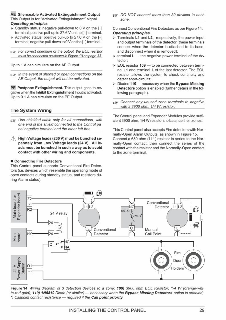
AE Silenceable Activated Extinguishment Output
This Output is for “Activated Extinguishment” signal.
Operating principles
� Standby status: negative pull-down to 0 V on the [+]
terminal; positive pull-up to 27.6 V on the [–] terminal.
� Activated status: positive pull-up to 27.6 V on the [+]
terminal; negative pull-down to 0 V on the [–] terminal.
� For correct operation of the output, the EOL resistor
must be connected as shown in Figure 19 on page 33.
Up to 1 A can circulate on the AE Output.
� In the event of shorted or open connections on the
AE Output, the output will not be activated.
PE Postpone Extinguishment. This output goes to ne-gative when the Inhibit Extinguishment Input is activated.
Up to 0.1 A can circulate on the PE Output.
The System Wiring
�Use shielded cable only for all connections, with
one end of the shield connected to the Control pa-nel negative terminal and the other left free.
! High Voltage leads (230 V) must be bunched se-
parately from Low Voltage leads (24 V). All le-
ads must be bunched in such a way as to avoid
contact with other wiring and components.
� Connecting Fire Detectors
This Control panel supports Conventional Fire Detec-
tors (i.e. devices which resemble the operating mode of
open contacts during standby status, and resistors du-
ring Alarm status).
� DO NOT connect more than 30 devices to each
zone.
Connect Conventional Fire Detectors as per Figure 14.
Operating principles
� Terminals L1 and L2, respectively, the power input
and output terminals of the detector (these terminals
connect when the detector is attached to its base,
and disconnect when it is removed);
� terminal L — the negative power terminal of the de-tector;
� EOL resistor 109 — to be connected between termi-
nal L1 and terminal L of the last detector. The EOL
resistor allows the system to check continuity and
detect short-circuits;
� Diodes 110 — necessary when the Bypass Missing
Detectors option is enabled (further details in the fol-lowing paragraph).
�Connect any unused zone terminals to negative
with a 3900 ohm, 1/4 W resistor.
The Control panel and Expander Modules provide suffi-
cient 3900 ohm, 1/4 W resistors to balance their zones.
This Control panel also accepts Fire detectors with Nor-
mally-Open Alarm Outputs, as shown in Figure 15.
Connect a 680 ohm (111) resistor in series to the Nor-
mally-Open contact, then connect the series of the
contact with the resistor and the Normally-Open contact
to the zone terminal.
INSTALLING THE CONTROL PANEL 29
L1 L1NO
C
L2 L2
Z2
L L
NC
NA
24
24
C
R2
–
+
24V
O1
–
+
ConventionalDetector
ConventionalDetector
ManualCall Point
680 �
Ma
inb
oa
rdo
rE
xpa
nd
er
bo
ard
Ma
inb
oa
rd
24 V relay
24
VP
ow
er
Su
pp
lyS
tatio
n
Fire
Door
Holders
270 �*
110
110
109
Figure 14 Wiring diagram of 3 detection devices to a zone: 109) 3900 ohm EOL Resistor, 1/4 W (orange-whi-te-red-gold); 110) 1N5819 Diode (or similar) — necessary when the Bypass Missing Detectors option is enabled;
*) Callpoint contact resistance — required if the Call point priority
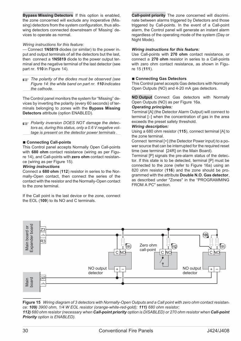
Bypass Missing Detectors If this option is enabled,
the zone concerned will exclude any inoperative (Mis-sing) detectors from the system configuration, thus allo-wing detectors connected downstream of ‘Missing’ de-vices to operate as normal.
Wiring instructions for this feature:
— Connect 1N5819 diodes (or similar) to the power in-put and output terminals of all the detectors but the last,
then connect a 1N5819 diode to the power output ter-minal and the negative terminal of the last detector (see
part nr. 110 in Figure 14).
� The polarity of the diodes must be observed (see
Figure 14: the white band on part nr. 110 indicates
the cathode.
The Control panel monitors the system for “Missing” de-vices by inverting the polarity (every 60 seconds) of ter-minals belonging to zones with the Bypass Missing
Detectors attribute (option ENABLED).
� Polarity inversion DOES NOT damage the detec-tors as, during this status, only a 0.6 V negative vol-tage is present on the detector power terminals .
� Connecting Call-points
This Control panel accepts Normally Open Call-points
with 680 ohm contact resistance (wiring as per Figu-re 14), and Call-points with zero ohm contact resistan-ce (wiring as per Figure 15).
Wiring instructions
Connect a 680 ohm (112) resistor in series to the Nor-mally-Open contact, then connect the series of the
contact with the resistor and the Normally-Open contact
to the zone terminal.
If the Call point is the last device or the zone, connect
the EOL (109) to its NO and C terminals.
Call-point priority The zone concerned will discrimi-nate between alarms triggered by Detectors and those
triggered by Call-points. In the event of a Call-point
alarm, the Control panel will generate an instant alarm
regardless of the operating mode of the system (Day or
Night Mode).
Wiring instructions for this feature:
Use Call-points with 270 ohm contact resistance, or
connect a 270 ohm resistor in series to a Call-points
with zero ohm contact resistance, as shown in Figu-re 15 (111).
� Connecting Gas Detectors
This Control panel accepts Gas detectors with Normally
Open Outputs (NO) and 4-20 mA gas detectors.
NO Output Connect Gas detectors with Normally
Open Outputs (NO) as per Figure 16a.
Operating principles:
Terminal [A] (the Detector Alarm Output) will connect to
terminal [–] when the concentration of gas in the area
exceeds the preset safety threshold.
Wiring description:
Using a 680 ohm resistor (115), connect terminal [A] to
the zone terminal.
Connect terminal [+] (the Detector Power input) to a po-wer source that can be interrupted for the required reset
time (see terminal [24R] on the Main Board).
Terminal [P] signals the pre-alarm status of the detec-tor. If this state is to be detected, terminal [P] must be
connected to the zone (refer to Figure 16a) using an
820 ohm resistor (116) and the zone should be pro-grammed with the attribute Double N.O. Gas detector,
as described under "Zones" in the “PROGRAMMING
FROM A PC" section.
30 Conventional Fire Panels J424/J408
NOC
Z3
R3
24R
NOC NOC
Zero ohmcall-pointM
ain
bo
ard
or
Expa
nd
er
bo
ard
Ma
inb
oa
rd
112
NO outputdetector
111 111
NO outputdetector
109
Figure 15 Wiring diagram of 3 detectors with Normally-Open Outputs and a Call point with zero ohm contact resistan-ce: 109) 3900 ohm, 1/4 W EOL resistor (orange-white-red-gold); 111) 680 ohm resistor;
112) 680 ohm resistor (necessary when Call-point priority option is DISABLED) or 270 ohm resistor when Call-point
Priority option is ENABLED).

� If terminal [P] is used, terminal [A] must also have
an 820 ohm resistor.
The Repeat Output of the zone can be set up to inter-rupt the gas flow in the event of an alarm (wiring as per
Figure 16a — see terminal [R4]).
If zone Z4 generates an alarm (or pre-alarm — when
the Pre-Alarm on R Output option is ENABLED), ter-minal [R4] will pull down to 0 V (negative) thus activating
the relay which in turn will latch the Switching Power
supply to the Electrovalve.
� The current draw of Electrovalves must be provided by
an external power source (e.g. BXM Power Station).
4 - 20 mA Gas detectors 4 - 20 mA Gas detectors
can be connected to terminals [Z1] ONLY on the Main
Board and Expander Module, as per Figure 16b.
Operating principles
The current draw of terminal [S] varies from 4 to 20 mA
in accordance with the concentration of gas present in
the area.
Wiring description
The [–] terminal is the negative power terminal.
Connect a 470 ohm, 2 W (113) between terminal [S]
and terminal [–] of the detector.
Connect [+] terminal (positive power input) to a power
source that can be interrupted for the required reset
time (see terminal [24R] on the Main Board).
� Terminal [Z1] accepts ONE 4 - 20 mA Gas detec-
tor ONLY. If you are connecting a 4 - 20 mA Gas
detector to terminal [Z1] of an Expander Module,
remove the Jumper (62) (marked GAS on the
PCB), and ENABLE the Gas Detector option of the
respective zone (i.e. Zone nr. 1 for the Main Board,
Zone nr. 9 for Expander Module nr. 1, zone nr. 17
for Expander Module nr. 2).
INSTALLING THE CONTROL PANEL 31
Z4
R4
24R
A P A P
Z1
R1
24R
Gaselectrovalve
O2
Power supplystation
S
NC
NA
24
24
C
24 V relay24V
NO outputgas
detector
Ma
inb
oa
rdo
rE
xpa
nd
er
bo
ard
Ma
inb
oa
rd
115 115
Ma
inb
oa
rdo
rE
xpa
nd
er
bo
ard
Ma
inb
oa
rd
Ma
inb
oa
rd
113
a) b)
4 - 20 mAgas detector
109
116 116
Figure 16 Wiring diagram of a Gas detector with Normally-Open Output (a) and a 4 - 20 mA Gas detector (b):
109) 3900 ohm, 1/4 W EOL Resistor (orange-white-red-gold); 111) 680 ohm resistor; 113) 470 ohm resistor, 2 W; 115) a
680 ohm resistor if the option Double N.O. Gas detector is disabled, or an 820 ohm resistor if the option is enabled;
116) an 820 ohm resistor should be used only if the option Double N.O. Gas detector is enabled
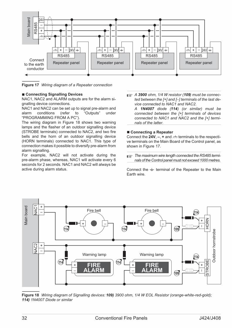
� Connecting Signalling Devices
NAC1, NAC2 and ALARM outputs are for the alarm si-gnalling device connections.
NAC1 and NAC2 can be set up to signal pre-alarm and
alarm conditions (refer to “Outputs” under
“PROGRAMMING FROM A PC”).
The wiring diagram in Figure 18 shows two warning
lamps and the flasher of an outdoor signalling device
(STROBE terminals) connected to NAC2, and two fire
bells and the horn of an outdoor signalling device
(HORN terminals) connected to NAC1. This type of
connection makes it possible to diversify pre-alarm from
alarm signalling.
For example, NAC2 will not activate during the
pre-alarm phase, whereas, NAC1 will activate every 6
seconds for 2 seconds. NAC1 and NAC2 will always be
active during alarm status.
� A 3900 ohm, 1/4 W resistor (109) must be connec-
ted between the [+] and [–] terminals of the last de-
vice connected to NAC1 and NAC2.
A 1N4007 diode (114) (or similar) must be
connected between the [+] terminals of devices
connected to NAC1 and NAC2 and the [+] termi-
nals of the latter.
� Connecting a Repeater
Connect the 24V, –, + andM terminals to the respecti-ve terminals on the Main Board of the Control panel, as
shown in Figure 17.
� The maximum wire length connected the RS485 termi-nals of the Control panel must not exceed 1000 metres.
Connect the - terminal of the Repeater to the Main
Earth wire.
32 Conventional Fire Panels J424/J408
24V
RS
48
5
24V
RS485
24V
RS485
24V
RS485
24V
RS485
Ma
inb
oa
rd
Repeater panelRepeater panelRepeater panelRepeater panelConnect
to the earthconductor
Figure 17 Wiring diagram of a Repeater connection
–+ –+
NA
C1
FIREALARM–
+ FIREALARM–
+
HO
RN
ST
RO
BE
NA
C2
Ou
tdo
or
ho
rnstr
ob
e
Ma
inb
oa
rd
114 114
114Fire bell Fire bell
Warning lamp114
114 114
Warning lamp
109
109
Figure 18 Wiring diagram of Signalling devices: 109) 3900 ohm, 1/4 W EOL Resistor (orange-white-red-gold);
114) 1N4007 Diode or similar
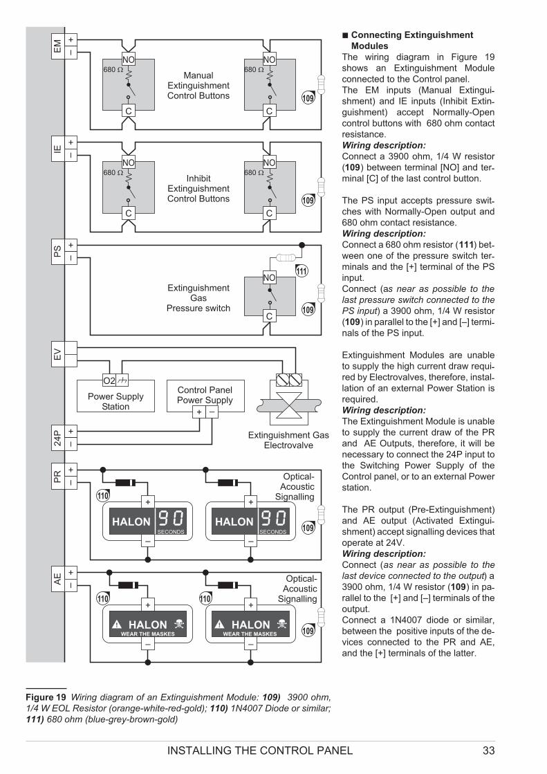
� Connecting Extinguishment
Modules
The wiring diagram in Figure 19
shows an Extinguishment Module
connected to the Control panel.
The EM inputs (Manual Extingui-shment) and IE inputs (Inhibit Extin-guishment) accept Normally-Open
control buttons with 680 ohm contact
resistance.
Wiring description:
Connect a 3900 ohm, 1/4 W resistor
(109) between terminal [NO] and ter-minal [C] of the last control button.
The PS input accepts pressure swit-ches with Normally-Open output and
680 ohm contact resistance.
Wiring description:
Connect a 680 ohm resistor (111) bet-ween one of the pressure switch ter-minals and the [+] terminal of the PS
input.
Connect (as near as possible to the
last pressure switch connected to the
PS input) a 3900 ohm, 1/4 W resistor
(109) in parallel to the [+] and [–] termi-nals of the PS input.
Extinguishment Modules are unable
to supply the high current draw requi-red by Electrovalves, therefore, instal-lation of an external Power Station is
required.
Wiring description:
The Extinguishment Module is unable
to supply the current draw of the PR
and AE Outputs, therefore, it will be
necessary to connect the 24P input to
the Switching Power Supply of the
Control panel, or to an external Power
station.
The PR output (Pre-Extinguishment)
and AE output (Activated Extingui-shment) accept signalling devices that
operate at 24V.
Wiring description:
Connect (as near as possible to the
last device connected to the output) a
3900 ohm, 1/4 W resistor (109) in pa-rallel to the [+] and [–] terminals of the
output.
Connect a 1N4007 diode or similar,
between the positive inputs of the de-vices connected to the PR and AE,
and the [+] terminals of the latter.
INSTALLING THE CONTROL PANEL 33
O2
EM
PS
NO
C
NO
C
NO
C
NO
C
IEE
VP
R2
4P
AE
–
+
HALONWEAR THE MASKES
–
+
HALONWEAR THE MASKES
–
+
HALONSECONDS
–
+
HALONSECONDS
NO
C
ManualExtinguishmentControl Buttons
680 � 680 �
680 � 680 �
Power SupplyStation
Control PanelPower Supply
InhibitExtinguishmentControl Buttons
ExtinguishmentGas
Pressure switch
Extinguishment GasElectrovalve
Optical-Acoustic
Signalling
Optical-Acoustic
Signalling110 110
109
110
111
109
109
109
109
Figure 19 Wiring diagram of an Extinguishment Module: 109) 3900 ohm,
1/4 W EOL Resistor (orange-white-red-gold); 110) 1N4007 Diode or similar;
111) 680 ohm (blue-grey-brown-gold)
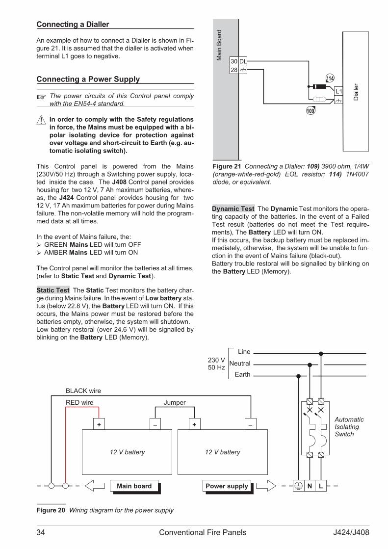
Connecting a Dialler
An example of how to connect a Dialler is shown in Fi-gure 21. It is assumed that the dialler is activated when
terminal L1 goes to negative.
Connecting a Power Supply
� The power circuits of this Control panel comply
with the EN54-4 standard.
! In order to comply with the Safety regulations
in force, the Mains must be equipped with a bi-
polar isolating device for protection against
over voltage and short-circuit to Earth (e.g. au-
tomatic isolating switch).
This Control panel is powered from the Mains
(230V/50 Hz) through a Switching power supply, loca-ted inside the case. The J408 Control panel provides
housing for two 12 V, 7 Ah maximum batteries, where-as, the J424 Control panel provides housing for two
12 V, 17 Ah maximum batteries for power during Mains
failure. The non-volatile memory will hold the program-med data at all times.
In the event of Mains failure, the:
� GREEN Mains LED will turn OFF
� AMBER Mains LED will turn ON
The Control panel will monitor the batteries at all times,
(refer to Static Test and Dynamic Test).
Static Test The Static Test monitors the battery char-ge during Mains failure. In the event of Low battery sta-tus (below 22.8 V), the Battery LED will turn ON. If this
occurs, the Mains power must be restored before the
batteries empty, otherwise, the system will shutdown.
Low battery restoral (over 24.6 V) will be signalled by
blinking on the Battery LED (Memory).
Dynamic Test The Dynamic Test monitors the opera-ting capacity of the batteries. In the event of a Failed
Test result (batteries do not meet the Test require-ments), The Battery LED will turn ON.
If this occurs, the backup battery must be replaced im-mediately, otherwise, the system will be unable to fun-ction in the event of Mains failure (black-out).
Battery trouble restoral will be signalled by blinking on
the Battery LED (Memory).
34 Conventional Fire Panels J424/J408
LMain board N
AutomaticIsolatingSwitch
+ –
12 V battery
Line
Neutral
Earth
230 V50 Hz
+ –
12 V battery
Power supply
RED wire
BLACK wire
Jumper
Figure 20 Wiring diagram for the power supply
L1
DL30
28
Dia
ller
Ma
inB
oa
rd
114
109
Figure 21 Connecting a Dialler: 109) 3900 ohm, 1/4W
(orange-white-red-gold) EOL resistor; 114) 1N4007
diode, or equivalent.

� Connecting the Mains Supply
Work carefully through the following steps (refer to the
figures on pages 12, 14, 18 and 19).
1. Locate the backup batteries in the housing 20.
2. Using the Jumper (supplied), connect the batteries
in series.
3. Observing the battery polarity, connect the battery
terminals to the wires 60.
� If you are connecting 17 Ah batteries, you must re-
place the wire 60 and jumper connectors.
� J424: Use 17 Ah @ 12 V YUASA NP 17-12 FR bat-teries;
J408: Use 7Ah @ 12 V YUASA NP7-12 FR batte-ries; or similar with case flame class UL94-V2 (or
higher).
4. Connect the Earth wire to the [Q] terminal on the
terminal board 53.
5. Connect the Neutral wire to terminal [N], and the
Line wire to terminal [L] on the terminal board 53.
�The Control panel will reset on power up.
! DO NOT allow the power cable to cross over ot-her wiring (see Figure 22a). The power cable
must be routed as per Figure 22c and held
firmly in place by a cable tie (see Figure 22b).
� Thermal Probe
This Control panel supports the KST thermal probe.
The probe will optimize the battery charging process by
regulating the charge voltage in accordance with the
battery temperature.
Work carefully through the following instructions (refer
to the figure on pages 12, 14, 18 and 19):
1. Connect the probe 24 to the connector 38 on the
Main board of the Control panel.
2. Attach the probe to one of the batteries, in such a
way as to obtain optimum heat transfer.
3. Measure the Probe temperature.
4. Using the graph in Figure 23 and/or Table 3, find
the value (in accordance with the battery tempera-ture) that the output voltage of the Switching Power
Supply will be based on.
5. Using the trimmer 51, adjust the voltage on the ter-minal board 52 to the required value.
� NOTE: to verify the battery efficiency, the PCB will
measure the internal resistance. In order for this
measure is not distorted, you should use only the
cables supplied; cables that are longer and have
an insufficient section may erroneously simulate
the condition of inefficient battery.
INSTALLING THE CONTROL PANEL 35
AC
/NFG
+V
GN
D
B+
L
B–
GND
+V
AC
/L
F3
.1
5A
/2
5Ø
V
F6
.3
A/2
5Ø
V
AC
/NFG
+V
GN
D
B+
L
B–
GND
+V
AC
/L
F3
.1
5A
/2
5Ø
V
F6
.3
A/2
5Ø
V
a) b) c)
No YesFigure 22
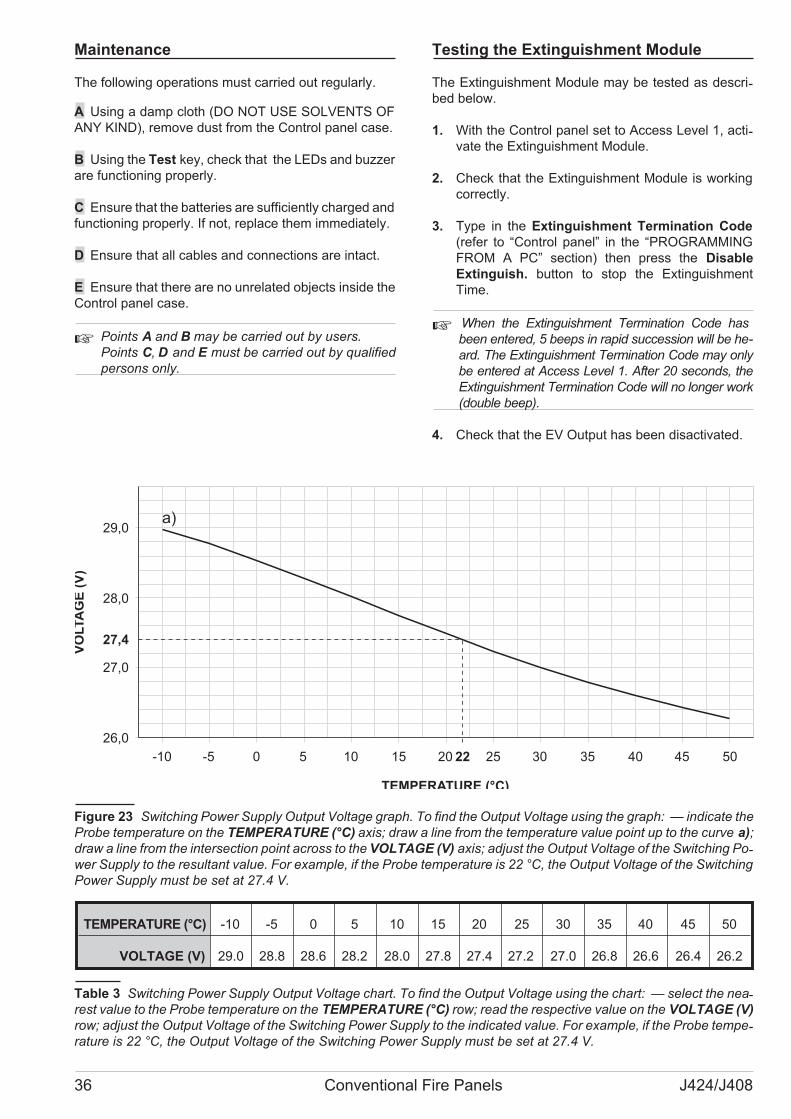
Maintenance
The following operations must carried out regularly.
A Using a damp cloth (DO NOT USE SOLVENTS OF
ANY KIND), remove dust from the Control panel case.
B Using the Test key, check that the LEDs and buzzer
are functioning properly.
C Ensure that the batteries are sufficiently charged and
functioning properly. If not, replace them immediately.
D Ensure that all cables and connections are intact.
E Ensure that there are no unrelated objects inside the
Control panel case.
� Points A and B may be carried out by users.
Points C, D and E must be carried out by qualified
persons only.
Testing the Extinguishment Module
The Extinguishment Module may be tested as descri-bed below.
1. With the Control panel set to Access Level 1, acti-vate the Extinguishment Module.
2. Check that the Extinguishment Module is working
correctly.
3. Type in the Extinguishment Termination Code
(refer to “Control panel” in the “PROGRAMMING
FROM A PC” section) then press the Disable
Extinguish. button to stop the Extinguishment
Time.
� When the Extinguishment Termination Code has
been entered, 5 beeps in rapid succession will be he-
ard. The Extinguishment Termination Code may only
be entered at Access Level 1. After 20 seconds, the
Extinguishment Termination Code will no longer work
(double beep).
4. Check that the EV Output has been disactivated.
36 Conventional Fire Panels J424/J408
TEMPERATURE (°C) -10 -5 0 5 10 15 20 25 30 35 40 45 50
VOLTAGE (V) 29.0 28.8 28.6 28.2 28.0 27.8 27.4 27.2 27.0 26.8 26.6 26.4 26.2
Table 3 Switching Power Supply Output Voltage chart. To find the Output Voltage using the chart: — select the nea-rest value to the Probe temperature on the TEMPERATURE (°C) row; read the respective value on the VOLTAGE (V)
row; adjust the Output Voltage of the Switching Power Supply to the indicated value. For example, if the Probe tempe-rature is 22 °C, the Output Voltage of the Switching Power Supply must be set at 27.4 V.
-10 -5 0 5 10 15 20 25 30 35 40 45 50
26,0
27,0
28,0
29,0
VO
LTA
GE
(V)
TEMPERATURE (°C)
a)
27,4
22
Figure 23 Switching Power Supply Output Voltage graph. To find the Output Voltage using the graph: — indicate the
Probe temperature on the TEMPERATURE (°C) axis; draw a line from the temperature value point up to the curve a);
draw a line from the intersection point across to the VOLTAGE (V) axis; adjust the Output Voltage of the Switching Po-wer Supply to the resultant value. For example, if the Probe temperature is 22 °C, the Output Voltage of the Switching
Power Supply must be set at 27.4 V.

PROGRAMMING FROM A PC
You can program this system from the Control panel or
from a computer, using the J400 application.
This section describes how to program the system from
a computer. If you intend programming the system from
the Control panel refer to the “PROGRAMMING FROM
THE PANEL” section.
Enrolling: Expander Modules
The Expander Modules page will allow you to enrol
Expander Modules, as follows.
� Enrol the Expander Modules (if installed).
A tick (�) indicates that the respective device is part of
the system.
Description This 16 character field will allow you to as-sign a label to the Expander Module. For example, if the
Expander Module monitors a particular part of the pre-mises, it may be useful to assign the name of the area
concerned. The assigned label will identify the Expan-der Module in all the operations it is involved in.
Enrolling: Extinguishment Modules
The Extinguishment Modules page will allow you to
enrol and set up Extinguishment Modules, as follows.
� Enrol the Extinguishment Modules (if installed).
A tick (�) indicates that the respective device is part of
the system.
Description This 16 character field will allow you to as-sign a label to the Extinguishment Module. For exam-ple, if the Extinguishment Module is intended for fire ex-tinction in a particular part of the premises, it may be
useful to assign the name of the area concerned. The
assigned label will identify the Extinguishment Module
in all the operations it is involved in.
Setting up an Extinguishment Module:
— select the Extinguishment Module on the left-hand
side of the page, then program the respective parame-ters on the right-hand side of the page, as follows.
PROGRAMMING FROM A PC 37
Figure 24 The Extinguishment Modules
page
� Activation Mode
This section will allow you to select the logic that will ac-tivate the Extinguishment phase, as follows.
� When some zones are in alarm, a condition of
pre-activation is signalled by the Control panel by
means of the ON Pre. Ext., which flashes quickly.
OR If you ENABLE this option, at least ONE of the Zo-nes — selected in the Zones chart — must detect alarm
conditions.
At least TWO If you ENABLE this option, at least TWO
of the Zones — selected in the Zones chart — must de-tect alarm conditions.
All If you ENABLE this option, ALL the Zones — selec-ted in the Zones chart — must detect alarm conditions.
� Times
This section will allow you to set the Extinguishment Ti-mes.
Pre-Extinguishment Time This field will allow you to
program a delay between verification of the Activation
Mode conditions and activation of the Electrovalve out-put ([EV] terminals). The Pre-Extinguishment output
([PR] terminals) will be active during the Pre-Extingui-shment Time.
Accepted values: 0 to 60 seconds, in steps of 1 second.
Default value: 20 seconds.
Extinguishment Time This field will allow you to set
the Extinguishment Time. If you DISABLE the Bistable
option, the EV output will restore to standby when the
programmed Extinguishment Time expires.
Accepted values: 0 to 300 seconds (5 minutes ) in steps
of 5 second.
Bistable If you ENABLE the Bistable option, the EV
output will restore to standby when the Control panel
Resets.
Manual Pre-Extinguishment Time Set the time that
must elapse from the point at which the EM Input is acti-vated to the point at which the Electrovalve Output ([EV]
terminals) are activated. During the Manual Pre-Extin-guishment Tim e, the Pre-Extinguishment Output
([PR] terminals) is activated.
Accepted values: 0 to 60 seconds, steps of 1 second.
Default value: 0 seconds.
Manual Pre-Extinguishment When the Manual
Pre-Extinguishment option is enabled, the Manual
Pre-Extinguishment Time may be set. When the option
is disabled, the Pre-Extinguishment Time will also be
used by the Control panel for manual activation.
Reset Inhibit Time This is the amount of time that
must elapse from the point at which the Extinguishment
Module is enabled to the point at which the module may
be reset. If the reset is performed during the Reset Inhi-bit Time, the Control panel will reset all systems (except
for the activated Extinguishment Module) for a few se-conds, after which it will return to an alarm condition.
Accepted values: 0 to 30 minutes, steps of 1 minute.
Default value: 0 minutes.
� Zones
This section will allow you to select the Zones which will
activate the Extinguishment phase.
�Manual Extinguishment Input
This field will allow you to set up the Standby status of
the Manual Extinguishment Input ([EM] terminals).
Normally Closed If this option is DISABLED (at Defa-ult), there must be a 3900 ohm resistance across the [+]
and [–] terminals of the EM Input during Standby status.
When this option is enabled, the resistor in standby
must be 680 ohm.
� Disable Extinguishment Input
This field will allow you to set up the Standby status of
the Disable Extinguishment Input ([IE] terminals).
Normally Closed If this option is DISABLED (at Defa-ult), there must be a 3900 ohm resistance across the [+]
and [–] terminals of the IE input during Standby status.
When this option is enabled, the resistor in standby
must be 680 ohm.
� Pressure Switch Input
This field will allow you to set up the Standby status of
the Pressure Switch Input ([PS] terminals).
Normally Closed If this option is DISABLED (at Defa-ult), there must be a 3900 ohm resistance across the [+]
and [–] terminals of the PS input during Standby status.
When this option is enabled, the resistor in standby
must be 680 ohm.
Enrolling: Power Supply Stations
The Power Supply Stations page will allow you to en-rol and set up Power Supply Stations, as follows.
� Enrol the Power Supply Stations (if installed).
A tick (�) indicates that the respective Power Supply
Station is part of the system.
Description This 16 character field will allow you to as-sign a label to the respective Power Supply Station. For
example, it may be useful to assign the name of the
area where the device is located. The assigned label
will identify the Power Supply Station in all the opera-tions it is involved in.
38 Conventional Fire Panels J424/J408
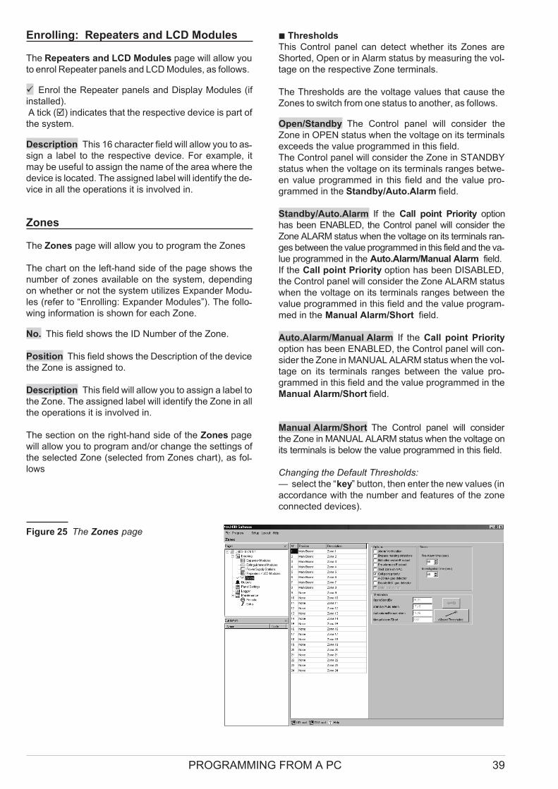
Enrolling: Repeaters and LCD Modules
The Repeaters and LCD Modules page will allow you
to enrol Repeater panels and LCD Modules, as follows.
� Enrol the Repeater panels and Display Modules (if
installed).
A tick (�) indicates that the respective device is part of
the system.
Description This 16 character field will allow you to as-sign a label to the respective device. For example, it
may be useful to assign the name of the area where the
device is located. The assigned label will identify the de-vice in all the operations it is involved in.
Zones
The Zones page will allow you to program the Zones
The chart on the left-hand side of the page shows the
number of zones available on the system, depending
on whether or not the system utilizes Expander Modu-les (refer to “Enrolling: Expander Modules”). The follo-wing information is shown for each Zone.
No. This field shows the ID Number of the Zone.
Position This field shows the Description of the device
the Zone is assigned to.
Description This field will allow you to assign a label to
the Zone. The assigned label will identify the Zone in all
the operations it is involved in.
The section on the right-hand side of the Zones page
will allow you to program and/or change the settings of
the selected Zone (selected from Zones chart), as fol-lows
� Thresholds
This Control panel can detect whether its Zones are
Shorted, Open or in Alarm status by measuring the vol-tage on the respective Zone terminals.
The Thresholds are the voltage values that cause the
Zones to switch from one status to another, as follows.
Open/Standby The Control panel will consider the
Zone in OPEN status when the voltage on its terminals
exceeds the value programmed in this field.
The Control panel will consider the Zone in STANDBY
status when the voltage on its terminals ranges betwe-en value programmed in this field and the value pro-grammed in the Standby/Auto.Alarm field.
Standby/Auto.Alarm If the Call point Priority option
has been ENABLED, the Control panel will consider the
Zone ALARM status when the voltage on its terminals ran-ges between the value programmed in this field and the va-lue programmed in the Auto.Alarm/Manual Alarm field.
If the Call point Priority option has been DISABLED,
the Control panel will consider the Zone ALARM status
when the voltage on its terminals ranges between the
value programmed in this field and the value program-med in the Manual Alarm/Short field.
Auto.Alarm/Manual Alarm If the Call point Priority
option has been ENABLED, the Control panel will con-sider the Zone in MANUAL ALARM status when the vol-tage on its terminals ranges between the value pro-grammed in this field and the value programmed in the
Manual Alarm/Short field.
Manual Alarm/Short The Control panel will consider
the Zone in MANUAL ALARM status when the voltage on
its terminals is below the value programmed in this field.
Changing the Default Thresholds:
— select the “key” button, then enter the new values (in
accordance with the number and features of the zone
connected devices).
PROGRAMMING FROM A PC 39
Figure 25 The Zones page
For step by step instructions on how to set up the Thre-sholds:
— select the “Wizard Thresholds” button.
� The “Wizard Thresholds” option can be used only
when the Control panel connected to a computer,
and is in “Programming” status (as described in the
“Downloading” paragraph).
� Options
This section will allow you to assign the Zone “attributes”.
Alarm Verification If this option is ENABLED, Alarm
will be verified as follows:
� the system will not generate a Control panel Alarm
when the Zone first detects Alarm conditions;
� the system will reset the Zone and start the Alarm
Verification Time (refer to “Panel settings”);
� if the Zone triggers another Alarm while the Alarm
Verification Time is running, the system will generate
a Control panel Alarm.
Bypass missing detectors If the Zone is wired to
bypass missing detectors, this option MUST BE ENABLED.
NON-Silenceable R Output If this option is
ENABLED, the Repeat Output of the Zone concerned
([Rn] terminal) CANNOT be Silenced.
Pre-Alarm on R Output If this option is ENABLED, the
Control panel will activate the Repeat Output of the Zone
concerned ([Rn] terminal) during the Pre-Alarm phase.
Test zone on NACs If this option is ENABLED, the
Control panel will activate the NAC1 and NAC2 Outputs
for 1 second when the Zone is undergoes testing.
Gas Detector If this option is ENABLED, it will be possible
to connect a 4 - 20 mA Gas Detector to the Zone terminal.
�The Gas Detector option can be ENABLED ONLY
for Zones 1, 9 and 17, respectively, the [Z1] termi-nals on the Main Board, and on Expander nr. 1 and
Expander nr. 2.
Double N.O. Gas Detector This option should be
enabled when using terminal [P] of the detector. When
this option is ENABLED, Zone thresholds will be auto-
matically adjusted to the connection illustrated in Figure
16a on page 31. Thus, the Control panel will be able to
detect 2 activation thresholds, one for the Pre-Alarm
and one for the Alarm.
R Output Bistable This option is only available when
the Double N.O. Gas detector is enabled.
In this case, when the option R Output Bistable is ena-
bled, the R Output of the zone is activated when the zone
exceeds the alarm threshold (or the pre-alarm threshold,
if the option “Pre-Alarm on R Output” is enabled) and re-
turns to standby when the zone falls below the alarm
threshold, irrespectively of the Control panel status.
If the option R Output Bistable is disabled (factory de-
fault), the R Output returns to standby when the Control
panel is reset.
� Times
Pre-Alarm Time This field will allow you to program the
delay between the Zone Alarm and the Control panel Alarm.
� If several Zones trigger Alarms within seconds of
one another, the Control panel will generate an
Alarm when the shortest Pre-Alarm Time of all the
Zones concerned expires.
Accepted values: 0 to 300 seconds (5 minutes), in steps
of 10 seconds.
Default setting: 60 seconds.
Investigation Time This field wilI allow you to program
an “interval” that will override the Pre-Alarm Time. This
“interval” will allow users time to investigate fire alerts.
It will be applied when the Ack/Evac. key is pressed for
less than 5 seconds at Access Level 2 (Keyswitch
ENABLED or PIN Code entered).
Accepted values: 0 to 300 seconds (5 minutes), in steps
of 10 seconds
Default value: 60 seconds.
Outputs
The Outputs page controls the pulse pattern for
Pre-Alarm (Alert) and/or Alarm (Evacuate) signalling on
the NAC1 and NAC2 outputs, and Alarm (Evacuate) si-gnalling on the ALARM output.
The pattern is represented by a series of bells, each bell
representing a second.
The configuration of the RED and WHITE backgrounds
(for On and Off respectively e.g. all RED indicates conti-nuously On) determines the respective pulse pattern.
For example, the output devices (connected to
NAC1and NAC2) can be configured to have one audi-ble output for Pre-Alarm (Alert) and a different audible
output for Alarm (Evacuate), thus allowing users to di-stinguish between the two conditions, as follows.
� NAC1 Output
Pre-Alarm pattern The bell chart will allow you to pro-gram the Pre-Alarm (Alert) pattern of NAC1.
� = Output OFF for 1 second;
� = Output ON for 1 second.
Pre-Alarm Default setting: NAC1 will turn ON for 2 se-conds then turn OFF for 6 seconds.
Alarm pattern To be set up in the same way as the
Pre-Alarm pattern of NAC1 but for the Alarm pattern.
Default setting: NAC1 is continuous.
40 Conventional Fire Panels J424/J408

� NAC2 Output
Pre-Alarm pattern To be set up in the same way as
the Pre-Alarm pattern of NAC1 but for the Pre-Alarm
pattern of NAC2.
Pre-Alarm Default setting: NAC2 WILL NOT ACTIVATE
during the Pre-Alarm Time.
Alarm pattern To be set up in the same way as the
Alarm pattern of NAC1 but for the Alarm pattern of NAC2.
Default setting: NAC2 is continuous.
Bistable If this option is enabled, the NAC2 Output
returns to standby when all zones have returned to
standby, irrespectively of the Control panels’ status. If
this option is disabled (factory default), the NAC2 Out-put returns to standby when the Control panel is reset.
� If the Bistable option is enabled, this will void com-
pliance with Standard EN54-2 of the NAC2 Output.
� ALARM Output
Alarm Pattern To be set up in the same way as NAC1
but for the Alarm pattern of the ALARM Output.
Default setting: the Alarm Output is continuous.
NON-Silenceable If this option is ENABLED, the
ALARM Output cannot be SILENCED.
� OC Output Events
This section will allow you to assign one or more of the
following events to the OC Output ([OC] terminal), as
follows.
Alarm If you assign this event, the OC Output will acti-vate when the Control panel generates an Alarm, and
will restore to standby when the Control panel Resets.
Pre-Alarm If you assign this event, the OC Output will
activate when the Control panel generates Pre-Alarm,
and will restore to standby when the Control panel ge-nerates an Alarm.
Fault If you assign this event, the OC Output will acti-vate when the system detects trouble, and will restore
when the trouble clears.
Reset If you assign this event, the OC Output will acti-vate when the system generates Reset, and will remain
active until Reset is completed.
Disable If you assign this event, the OC Output will ac-tivate when Zones are Disabled, and will restore when
the Zones are Re-Enabled.
Test If you assign this event, the OC Output will acti-vate when Zones are in Test status, and will restore
when Test status ends.
Double Knock If you assign this event, the OC Output
will activate when TWO or more Zones generate Alarm,
and will restore to standby when the Control panel Re-sets.
� If you assign more than one event, the OC Output will
activate when one of the assigned events occurs,
and will Reset when ALL the assigned events end.
� DL Output
The Dialler Output ([DL] terminal) will activate when its
programmed delay expires. The delay countdown will
start when the Control panel generates Alarm status.
� If the Alarm is triggered from a Call point (connec-ted to a Zone with the Call point priority option
ENABLED), the DL Output will activate instantly.
Alarm Signalling Delay This field will allow you to pro-gram the Dialler Output delay.
Accepted values: 0 through 600 seconds (10 minutes),
in steps of 10 seconds;
Default setting: 60 seconds.
�The Alarm Signalling Delay will be suspended
during the Silence phase.
PROGRAMMING FROM A PC 41
Figure 26 The Outputs page
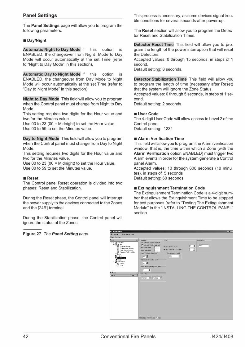
Panel Settings
The Panel Settings page will allow you to program the
following parameters.
� Day/Night
Automatic Night to Day Mode If this option is
ENABLED, the changeover from Night Mode to Day
Mode will occur automatically at the set Time (refer
to “Night to Day Mode” in this section).
Automatic Day to Night Mode If this option is
ENABLED, the changeover from Day Mode to Night
Mode will occur automatically at the set Time (refer to
“Day to Night Mode” in this section).
Night to Day Mode This field will allow you to program
when the Control panel must change from Night to Day
Mode.
This setting requires two digits for the Hour value and
two for the Minutes value.
Use 00 to 23 (00 = Midnight) to set the Hour value.
Use 00 to 59 to set the Minutes value.
Day to Night Mode This field will allow you to program
when the Control panel must change from Day to Night
Mode.
This setting requires two digits for the Hour value and
two for the Minutes value.
Use 00 to 23 (00 = Midnight) to set the Hour value.
Use 00 to 59 to set the Minutes value.
� Reset
The Control panel Reset operation is divided into two
phases: Reset and Stabilization.
During the Reset phase, the Control panel will interrupt
the power supply to the devices connected to the Zones
and the [24R] terminal.
During the Stabilization phase, the Control panel will
ignore the status of the Zones.
This process is necessary, as some devices signal trou-ble conditions for several seconds after power-up.
The Reset section will allow you to program the Detec-tor Reset and Stabilization Times.
Detector Reset Time This field will allow you to pro-gram the length of the power interruption that will reset
the Detectors.
Accepted values: 0 through 15 seconds, in steps of 1
second.
Default setting: 8 seconds.
Detector Stabilization Time This field will allow you
to program the length of time (necessary after Reset)
that the system will ignore the Zone Status.
Accepted values: 0 through 5 seconds, in steps of 1 se-cond.
Default setting: 2 seconds.
� User Code
The 4-digit User Code will allow access to Level 2 of the
Control panel.
Default setting: 1234
� Alarm Verification Time
This field will allow you to program the Alarm verification
window, that is, the time within which a Zone (with the
Alarm Verification option ENABLED) must trigger two
Alarm events in order for the system generate a Control
panel Alarm.
Accepted values: 10 through 600 seconds (10 minu-tes), in steps of 5 seconds
Default setting: 60 seconds
� Extinguishment Termination Code
The Extinguishment Termination Code is a 4-digit num-ber that allows the Extinguishment Time to be stopped
for test purposes (refer to “Testing The Extinguishment
Module” in the “INSTALLING THE CONTROL PANEL”
section.
42 Conventional Fire Panels J424/J408
Figure 27 The Panel Setting page
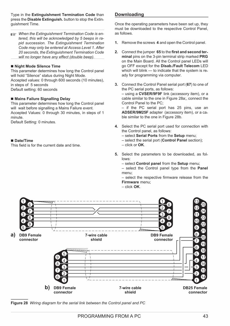
Type in the Extinguishment Termination Code than
press the Disable Extinguish. button to stop the Extin-guishment Time.
� When the Extinguishment Termination Code is en-
tered, this will be acknowledged by 5 beeps in ra-
pid succession. The Extinguishment Termination
Code may only be entered at Access Level 1. After
20 seconds, the Extinguishment Termination Code
will no longer have any effect (double beep).
� Night Mode Silence Time
This parameter determines how long the Control panel
will hold “Silence” status during Night Mode.
Accepted values: 0 through 600 seconds (10 minutes),
in steps of 5 seconds
Default setting: 60 seconds
� Mains Failure Signalling Delay
This parameter determines how long the Control panel
will wait before signalling a Mains Failure event.
Accepted Values: 0 through 30 minutes, in steps of 1
minute.
Default Setting: 0 minutes.
� Date/Time
This field is for the current date and time.
Downloading
Once the operating parameters have been set up, they
must be downloaded to the respective Control Panel,
as follows.
1. Remove the screws 4 and open the Control panel.
2. Connect the jumper 65 to the first and second ter-minal pins on the 3-pin terminal strip marked PRG
on the Main Board. All the Control panel LEDs will
go OFF except for the Disab./Fault Telecom LED
which will blink — to indicate that the system is re-ady for programming via computer.
3. Connect the Control Panel serial port (67) to one of
the PC serial ports, as follows:
– using a CVSER/9F9F link (accessory item), or a
cable similar to the one in Figure 28a;, connect the
Control Panel to the PC;
– if the PC serial port has 25 pins, use an
ADSER/9M25F adapter (accessory item), or a ca-ble similar to the one in Figure 28b.
4. Select the PC serial port used for connection with
the Control panel, as follows:
– select Serial Ports from the Setup menu;
– select the serial port (Control Panel section);
– click or OK.
5. Select the parameters to be downloaded, as fol-lows:
– select Control panel from the Setup menu;
– select the Control panel type from the Panel
menu;
– select the respective firmware release from the
Firmware menu;
– click OK.
PROGRAMMING FROM A PC 43
5
4
6
5
4
3
2
1
9
18
8
19
17
16
15
14
7
20
21
22
23
24
25
6
3
7
2
8
9
10
11
12
13
1
DB9 Femaleconnector
a)
b) 7-wire cableshield
DB25 Femaleconnector
5 5
4 49 9
8 8
7 7
6 6
3 3
2 2
1 1
DB9 Femaleconnector
7-wire cableshield
DB9 Femaleconnector
Figure 28 Wiring diagram for the serial link between the Control panel and PC

6. To download a specific page: click the DWLoad
button on the page in question.
To Download several pages:
– select the required page from the Pages menu,
right click, Select (a � on the page Icon indicates
that it will be downloaded);
– repeat the procedure for all the required Pages;
– right click again then select DWLoad.
� To download a group of pages, select the root.
For example: to download all the Configuration related
pages, select Configuration from the Pages menu; to
download All the Pages, select J400 from the Pages
menu.
7. To view the Control panel parameters — work care-fully through point 6 then select UPLoad instead of
DWLoad.
8. To exit the Programming session — connect the
jumper 65 to the second and third terminals on
the 3-pin terminal strip marked PRG on the Main
Board. The Control panel will Reset automatically.
� Restoring Factory Defaults
In order to restore factory defaults, press the Reset but-ton for 5 seconds when the Control panel is in Program-ming status. A series of beeps will signal that the
Control panel has restored the factory defaults.
44 Conventional Fire Panels J424/J408

PROGRAMMING FROM THE PANEL
Read through the following section carefully, in order to
get an overall view of how to use the Programming
Overlay during the various “Programming Phases”. For
details regarding the parameters of each phase, refer to
the respective paragraph in the “PROGRAMMING
FROM A PC” chapter.
Using the Programming Overlay
The Programming Overlay is set up in columns.
The LEDs in column A represent the Programming
Phases:�ZONES;�TIMES;OUTPUTS; PANEL;
� VARIOUS and � MODULES.
Columns B, C, D, E and F are divided into panes, each
pane providing a series of options. Each option is pre-ceded by a number, representing the Programming
Phase it belongs to (e.g.� Pre-alarm time — column C
belongs to the�TIMES Programming Phase).
The panes in column B have LEDs, those in columns C
(except for the “Next Phase” key), D, E and F have
LEDs and keys. During the programming session, the
LEDs and keys and will take on “Multi-Task” status, that
is, they will operate in accordance with the Program-ming Phase concerned.
� Some options must be ENABLED/DISABLED by
means of the Zone keys (Z1 through Z8 for the
J408; Z1 through Z 24 for the J424). The Program-
ming Overlay covers the keys of Zones 1 through 8
(Z1 . . . Z 8), however, there is no need to remove it,
as these keys are clearly indicated in columns E
and F.
Accessing the Programming session
1. Remove the screws 4 and open the Control panel.
2. Connect the jumper 65 to the first and second ter-minal pins on the 3-pin terminal strip marked PRG
on the Main Board. All the Control panel LEDs will
go OFF except for the Disab./Fault Telecom LED
which will blink — to indicate that the system is re-ady for programming via computer.
3. Press and hold the Disab./Fault Telecom key for at
least 2 seconds. The green Mains LED will blink and
the Amber Mains LED will go ON to indicate that the
system is ready for programming via the Control panel.
4. Remove the cut-outs (for the LEDs), and insert the
tabs of the Programming Overlay into the Zone la-bel slots, as shown in Figure 29.
5. Press the Next Phase key 9 then select the group of
parameters that you want to program: ZONES,
TIMES; OUTPUTS; PANEL or VARIOUS (refer to the
respective paragraph for details) or, if you want to
program the Extinguishment Modules, press and hold
(for at least 2 seconds) key 3 or key 6, respectively,
Extinguishment Module nr. 1 and Extinguishment
Module nr. 2 (refer to “Programming Modules” for de-tails). The respective LED in column A will turn On to
indicate the group of parameters concerned.
Exiting the Programming Session
Once programming has been completed, press key 9,
then connect the jumper 65 to the second and third ter-minals on the 3-pin terminal strip marked PRG on the
Main Board. The Control panel will Reset automatically.
� Press the Next Phase key 9 before repositioning the
jumper, otherwise, the settings will not be saved.
PROGRAMMING FROM THE PANEL 45
�
�
MMM�
�
�
MMM�
�
�
MMM�
�
�
MMM�
�
�
MMM�
�
�
MMM�
�
�
MMM�
��
MMM
�
���
4-20mA gas
1 sec
5 secN
���2 sec
C
N10 sec
���
Test on NACs
NAC1 Alarm4 sec
20 sec
���
NAC2 Alarm8 sec
40 sec
���
NON silen. R
ALARM16 sec
80 sec
���
OC output32 sec
160 sec
��
�
Alarm verific.
64 sec
320 sec
2 x N.O. gas
128 sec
��
640 sec
MODULES
VARIOUS
PANEL
OUTPUTS
TIMES
ZONES
�-�
�� �
Investigation timePre-alarm
Day modeReset timePre-exting. time
��
��
Zone 1Zone 1Fault
Exting. 1ALARM
LCD 1
��
��
Zone 5Zone 5
Power 1Zone 5
Rep. 1
��
�
Zone 2Zone 2Test
Exting. 2 LCD 2
��
��
Zone 6Zone 6
Power 2Zone 6
Rep. 2
��
��
Zone 3Zone 3
Expander 1Zone 3
LCD 3
��
��
Zone 7Zone 7
Power 3Zone 7
Rep. 3
��
��
Zone 4Zone 4
Expander 2Zone 4
LCD 4
��
��
Zone 8Zone 8
Power 4Zone 8
Rep. 4
�
Zone 2/Exting. 2��
�-�
�� �
Verification timeReset
Night mode
Man. pre-ext. t.NON silence. outs
�-�
�� �
Pre-alarm timeAlarm
User codeStabilization timeExtinguish. time
�-�
�� �
Silence timeDisablement
ClockConfiguration 1Reset Inhibit t.
�-
Configuration 2
�
��
DL output delayDouble knock
Date
Zones
�-
Configuration 2
�
��
DL output delayDouble knock
Date
Zones
1 2 3
4 5 6
7 8
9 0
��
��
Next OptionDecrease timeNext Output
Decrease timeDecrease time
�-�
��
Increase time
Mains OFF delayIncrease timeIncrease time
�Next phase
CBA E FD
Pre-alarm on R
Detect missing
Call-point alarm
NAC2 Pre-alarm
NAC1 Pre-alarm
Zone 1/Exting. 1�
�R out
bistable
Figure 29 Using the Programming Overlay with a J408 Control panel
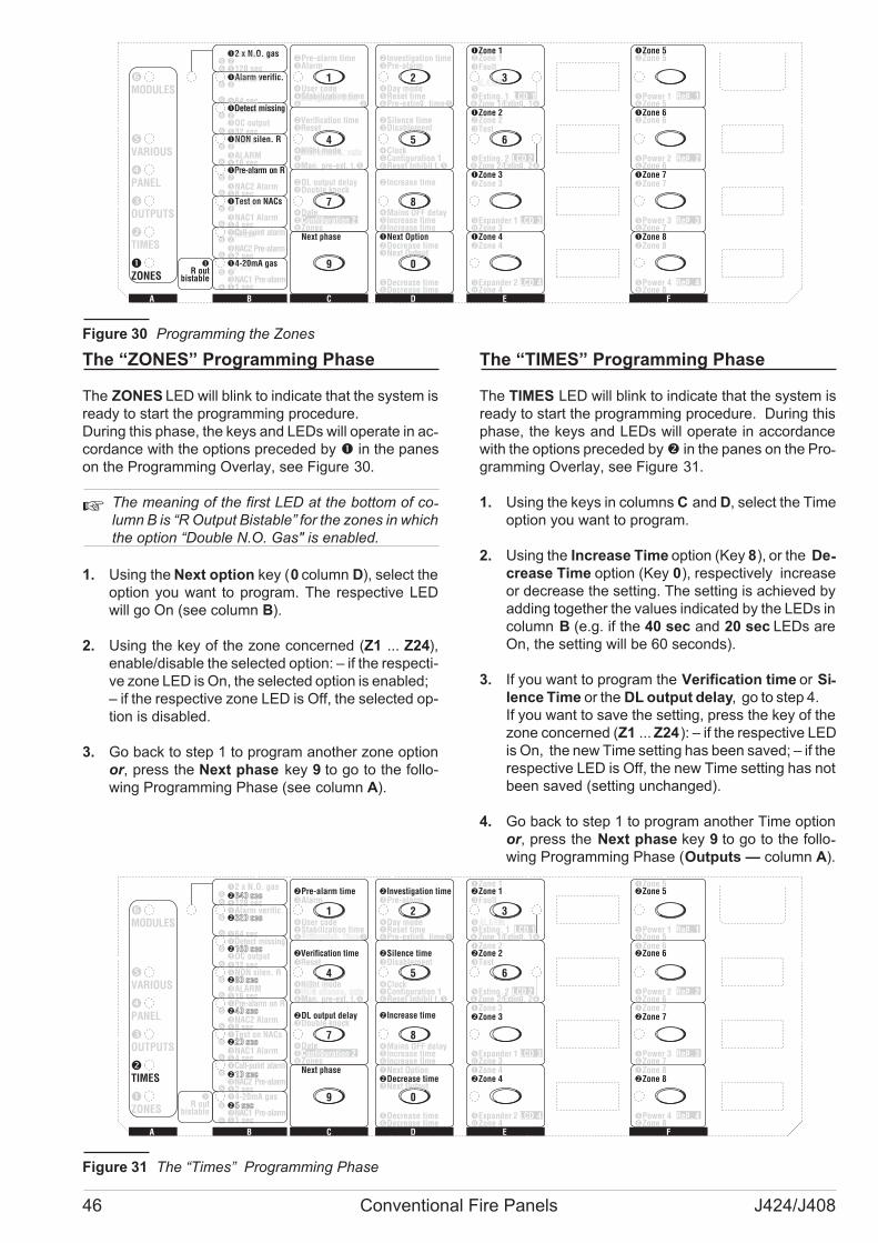
The “ZONES” Programming Phase
The ZONES LED will blink to indicate that the system is
ready to start the programming procedure.
During this phase, the keys and LEDs will operate in ac-cordance with the options preceded by � in the panes
on the Programming Overlay, see Figure 30.
�The meaning of the first LED at the bottom of co-lumn B is “R Output Bistable” for the zones in which
the option “Double N.O. Gas" is enabled.
1. Using the Next option key (0 column D), select the
option you want to program. The respective LED
will go On (see column B).
2. Using the key of the zone concerned (Z1 ... Z24),
enable/disable the selected option: – if the respecti-
ve zone LED is On, the selected option is enabled;
– if the respective zone LED is Off, the selected op-
tion is disabled.
3. Go back to step 1 to program another zone option
or, press the Next phase key 9 to go to the follo-
wing Programming Phase (see column A).
The “TIMES” Programming Phase
The TIMES LED will blink to indicate that the system is
ready to start the programming procedure. During this
phase, the keys and LEDs will operate in accordance
with the options preceded by� in the panes on the Pro-gramming Overlay, see Figure 31.
1. Using the keys in columns C and D, select the Time
option you want to program.
2. Using the Increase Time option (Key 8), or the De-crease Time option (Key 0), respectively increase
or decrease the setting. The setting is achieved by
adding together the values indicated by the LEDs in
column B (e.g. if the 40 sec and 20 sec LEDs are
On, the setting will be 60 seconds).
3. If you want to program the Verification time or Si-lence Time or the DL output delay, go to step 4.
If you want to save the setting, press the key of the
zone concerned (Z1 ... Z24): – if the respective LED
is On, the new Time setting has been saved; – if the
respective LED is Off, the new Time setting has not
been saved (setting unchanged).
4. Go back to step 1 to program another Time option
or, press the Next phase key 9 to go to the follo-wing Programming Phase (Outputs — column A).
46 Conventional Fire Panels J424/J408
�-
Configuration 2
DL output delayDouble knock
Date
Zones
�
��
MMM��
�
MMM��
�
MMM��
�
MMM��
�
MMM��
�
MMM��
�
MMM��
�
MMM
���
�4-20mA gas�
5 sec
N�1 sec
�C10 sec
N�2 sec
�Test on NACs�
20 sec
NAC1 Alarm�4 sec
�
NAC2 Alarm�8 sec
�NON silen. R�
80 sec
ALARM�16 sec
��
160 sec
OC output�32 sec
128 sec��
�2 x N.O. gas640 sec
MODULES
VARIOUS
PANEL
OUTPUTS
TIMES
ZONES
�-Investigation timePre-alarm
Day modeReset time
�
�� �Pre-exting. time
�Zone 1�Zone 1Fault
�ALARM
�Exting. 1 LCD 1
�Zone 5�Zone 5
�Power 1 Rep. 1�Zone 5
�Zone 2�Zone 2Test
�Exting. 2 LCD 2
�Zone 6�Zone 6
�Power 2 Rep. 2�Zone 6
�Zone 3�Zone 3
�Expander 1 LCD 3�Zone 3
�Zone 7�Zone 7
�Power 3 Rep. 3�Zone 7
�Zone 4�Zone 4
�Expander 2 LCD 4�Zone 4
�Zone 8�Zone 8
�Power 4 Rep. 4�Zone 8
�
Zone 2/Exting. 2��
�-Verification timeReset
Night mode
Man. pre-ext. t.
�
�� �
NON silence. outs
�-Pre-alarm timeAlarm
User codeStabilization time
�
�� �
Extinguish. time
�-Silence timeDisablement
ClockConfiguration 1Reset Inhibit t.
�
�� �
1 2 3
4 5 6
7 8
9 0
�Next Option�Decrease timeNext Output
�Decrease time�Decrease time
�-Increase time
Mains OFF delayIncrease timeIncrease time
�
��
�Next phase
CBA E FD
Pre-alarm on R
Detect missing
Call-point alarm
NAC2 Pre-alarm
NAC1 Pre-alarm
Zone 1/Exting. 1�
�R out
bistable
�Alarm verific.�
320 sec
�64 sec
�40 sec
Figure 30 Programming the Zones
MMM��
�
MMM��
�
MMM��
�
MMM��
�
MMM��
�
MMM��
�
MMM��
�
MMM
���
�4-20mA gas�5 secN�1 sec
�C�10 secN�2 sec
�Test on NACs�20 secNAC1 Alarm�4 sec
��40 secNAC2 Alarm�8 sec
�NON silen. R�80 secALARM�16 sec
��160 secOC output�32 sec
�Alarm verific.�320 sec
�64 sec
2 x N.O. gas��640 sec�128 sec
MODULES
VARIOUS
PANEL
OUTPUTS
TIMES
ZONES
�-�Investigation timePre-alarm
Day mode�Reset time� �Pre-exting. time
�Zone 1�Zone 1Fault
�ALARM�Exting. 1 LCD 1
�Zone 5�Zone 5
�Power 1 Rep. 1�Zone 5
�Zone 2�Zone 2Test
�Exting. 2 LCD 2
�Zone 6�Zone 6
�Power 2 Rep. 2�Zone 6
�Zone 3�Zone 3
�Expander 1 LCD 3�Zone 3
�Zone 7�Zone 7
�Power 3 Rep. 3�Zone 7
�Zone 4�Zone 4
�Expander 2 LCD 4�Zone 4
�Zone 8�Zone 8
�Power 4 Rep. 4�Zone 8
�
Zone 2/Exting. 2��
�-�Verification timeReset
Night mode�NON silence. outs� �Man. pre-ext. t.
�-�Pre-alarm timeAlarm
User code�Stabilization time� �Extinguish. time
�-�Silence timeDisablement
Clock�Configuration 1� �Reset Inhibit t.
�-
Configuration 2
�DL output delay
��
Double knock
Date
Zones
1 2 3
4 5 6
7 8
9 0
�Next Option�Decrease timeNext Output
�Decrease time�Decrease time
�-�Increase time
Mains OFF delay�Increase time�Increase time
�Next phase
CBA E FD
Pre-alarm on R
Detect missing
Call-point alarm
NAC2 Pre-alarm
NAC1 Pre-alarm
Zone 1/Exting. 1�
�R out
bistable
Figure 31 The “Times” Programming Phase
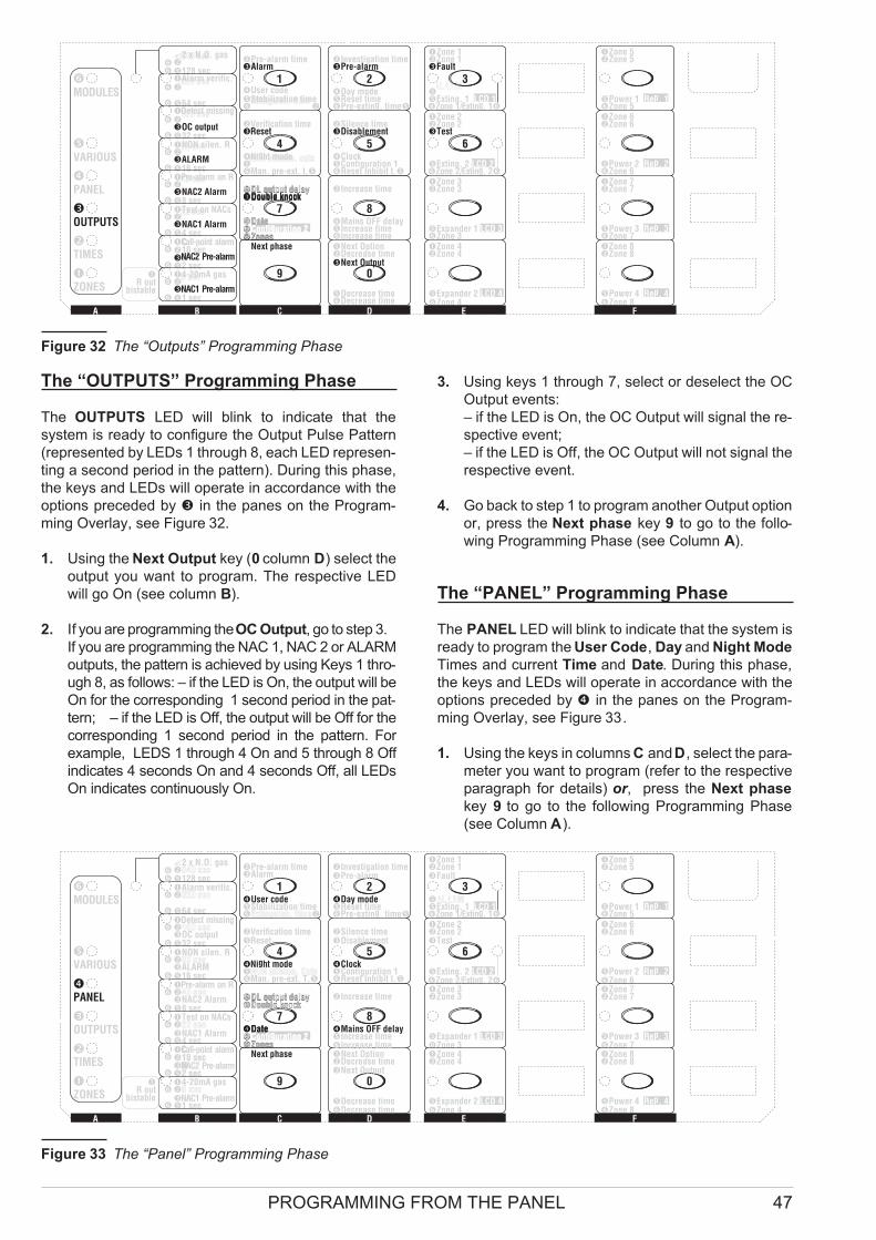
The “OUTPUTS” Programming Phase
The OUTPUTS LED will blink to indicate that the
system is ready to configure the Output Pulse Pattern
(represented by LEDs 1 through 8, each LED represen-
ting a second period in the pattern). During this phase,
the keys and LEDs will operate in accordance with the
options preceded by in the panes on the Program-
ming Overlay, see Figure 32.
1. Using the Next Output key (0 column D) select the
output you want to program. The respective LED
will go On (see column B).
2. If you are programming theOC Output, go to step 3.
If you are programming the NAC 1, NAC 2 or ALARM
outputs, the pattern is achieved by using Keys 1 thro-
ugh 8, as follows: – if the LED is On, the output will be
On for the corresponding 1 second period in the pat-
tern; – if the LED is Off, the output will be Off for the
corresponding 1 second period in the pattern. For
example, LEDS 1 through 4 On and 5 through 8 Off
indicates 4 seconds On and 4 seconds Off, all LEDs
On indicates continuously On.
3. Using keys 1 through 7, select or deselect the OC
Output events:
– if the LED is On, the OC Output will signal the re-
spective event;
– if the LED is Off, the OC Output will not signal the
respective event.
4. Go back to step 1 to program another Output option
or, press the Next phase key 9 to go to the follo-
wing Programming Phase (see Column A).
The “PANEL” Programming Phase
The PANEL LED will blink to indicate that the system is
ready to program the User Code, Day and Night Mode
Times and current Time and Date. During this phase,
the keys and LEDs will operate in accordance with the
options preceded by in the panes on the Program-
ming Overlay, see Figure 33.
1. Using the keys in columns C andD, select the para-
meter you want to program (refer to the respective
paragraph for details) or, press the Next phase
key 9 to go to the following Programming Phase
(see Column A).
PROGRAMMING FROM THE PANEL 47
MMM��
�
MMM��
�
MMM��
�
MMM��
�
MMM��
�
MMM��
�
MMM��
�
MMM
���
�4-20mA gas�
5 sec
N�1 sec
��
�
C10 secN2 sec
�Test on NACs�
20 sec
NAC1 Alarm�4 sec
��
40 sec
NAC2 Alarm�8 sec
�NON silen. R�
80 sec
ALARM�16 sec
��
160 sec
OC output�32 sec
�Alarm verific.�
320 sec
�64 sec
2 x N.O. gas �
640 sec
�128 sec
MODULES
VARIOUS
PANEL
OUTPUTS
TIMES
ZONES
�-�Investigation timePre-alarm
Day mode�Reset time� �Pre-exting. time
�Zone 1�Zone 1Fault
�ALARM
�Exting. 1 LCD 1
�Zone 5�Zone 5
�Power 1 Rep. 1�Zone 5
�Zone 2�Zone 2Test
�Exting. 2 LCD 2
�Zone 6�Zone 6
�Power 2 Rep. 2�Zone 6
�Zone 3�Zone 3
�Expander 1 LCD 3�Zone 3
�Zone 7�Zone 7
�Power 3 Rep. 3�Zone 7
�Zone 4�Zone 4
�Expander 2 LCD 4�Zone 4
�Zone 8�Zone 8
�Power 4 Rep. 4�Zone 8
�
Zone 2/Exting. 2��
�-�Verification timeReset
Night mode�
NON silence. outs
� �Man. pre-ext. t.
�-�Pre-alarm timeAlarm
User code�Stabilization time� �
Extinguish. time
�-�Silence timeDisablement
Clock�Configuration 1� �Reset Inhibit t.
�-
Configuration 2
�
��
DL output delayDouble knock
Date
Zones
�-�DL output delayDouble knock
Date�Configuration 2�Zones
1 2 3
4 5 6
7 8
9 0
�Next Option�Decrease timeNext Output
�Decrease time�Decrease time
�-�Increase time
Mains OFF delay�Increase time�Increase time
�Next phase
CBA E FD
Pre-alarm on R
Detect missing
Call-point alarm
NAC2 Pre-alarm
NAC1 Pre-alarm
Zone 1/Exting. 1�
�R out
bistable
Figure 32 The “Outputs” Programming Phase
MMM��
�
MMM��
�
MMM��
�
MMM��
�
MMM��
�
MMM��
�
MMM��
�
MMM
���
�4-20mA gas�5 secN�1 sec
���
C10 secN2 sec
�Test on NACs�20 secNAC1 Alarm�4 sec
��40 secNAC2 Alarm�8 sec
�NON silen. R�80 secALARM�16 sec
��160 secOC output�32 sec
�Alarm verific.�320 sec
�64 sec
2 x N.O. gas �640 sec�128 sec
MODULES
VARIOUS
PANEL
OUTPUTS
TIMES
ZONES
�-�Investigation timePre-alarm
Day mode�Reset time� �Pre-exting. time
�Zone 1�Zone 1Fault
�ALARM�Exting. 1 LCD 1
�Zone 5�Zone 5
�Power 1 Rep. 1�Zone 5
�Zone 2�Zone 2Test
�Exting. 2 LCD 2
�Zone 6�Zone 6
�Power 2 Rep. 2�Zone 6
�Zone 3�Zone 3
�Expander 1 LCD 3�Zone 3
�Zone 7�Zone 7
�Power 3 Rep. 3�Zone 7
�Zone 4�Zone 4
�Expander 2 LCD 4�Zone 4
�Zone 8�Zone 8
�Power 4 Rep. 4�Zone 8
�
Zone 2/Exting. 2��
�-�Verification timeReset
Night mode�NON silence. Outs� �Man. pre-ext. T.
�-�Pre-alarm timeAlarm
User code�Stabilization time� �Extinguish. time
�-�Silence timeDisablement
Clock�Configuration 1� �Reset Inhibit t.
�-
Configuration 2
�
��
DL output delayDouble knock
Date
Zones
�-�DL output delayDouble knock
Date�Configuration 2�Zones
1 2 3
4 5 6
7 8
9 0
�Next Option�Decrease timeNext Output
�Decrease time�Decrease time
�-�Increase time
Mains OFF delay�Increase time�Increase time
�Next phase
CBA E FD
Pre-alarm on R
Detect missing
Call-point alarm
NAC2 Pre-alarm
NAC1 Pre-alarm
Zone 1/Exting. 1�
�R out
bistable
Figure 33 The “Panel” Programming Phase
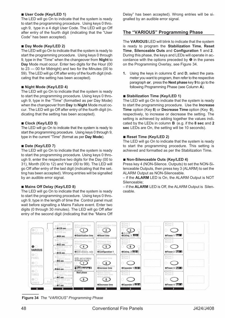
� User Code (Key/LED 1)
The LED will go On to indicate that the system is ready
to start the programming procedure. Using keys 0 thro-ugh 9, type in a 4 digit User Code. The LED will go Off
after entry of the fourth digit (indicating that the “User
Code” has been accepted).
� Day Mode (Key/LED 2)
The LED will go On to indicate that the system is ready to
start the programming procedure. Using keys 0 through
9, type in the “Time” when the changeover from Night to
Day Mode must occur. Enter two digits for the Hour (00
to 23 — 00 for Midnight) and two for the Minutes (00 to
59). The LED will go Off after entry of the fourth digit (indi-cating that the setting has been accepted).
� Night Mode (Key/LED 4)
The LED will go On to indicate that the system is ready
to start the programming procedure. Using keys 0 thro-ugh 9, type in the “Time” (formatted as per Day Mode)
when the changeover from Day to Night Mode must oc-cur. The LED will go Off after entry of the fourth digit (in-dicating that the setting has been accepted).
� Clock (Key/LED 5)
The LED will go On to indicate that the system is ready to
start the programming procedure. Using keys 0 through 9,
type in the current “Time” (format as per Day Mode).
� Date (Key/LED 7)
The LED will go On to indicate that the system is ready
to start the programming procedure. Using keys 0 thro-ugh 9, enter the respective two digits for the Day (00 to
31), Month (00 to 12) and Year (00 to 99). The LED will
go Off after entry of the last digit (indicating that the set-ting has been accepted). Wrong entries will be signalled
by an audible error signal.
�Mains Off Delay (Key/LED 8)
The LED will go On to indicate that the system is ready
to start the programming procedure. Using keys 0 thro-ugh 9, type in the length of time the Control panel must
wait before signalling a Mains Failure event. Enter two
digits (0 through 30 minutes). The LED will go Off after
entry of the second digit (indicating that the “Mains Off
Delay” has been accepted). Wrong entries will be si-gnalled by an audible error signal.
The “VARIOUS” Programming Phase
The VARIOUS LED will blink to indicate that the system
is ready to program the Stabilization Time, Reset
Time, Silenceable Outs and Configuration 1 and 2.
During this phase, the keys and LEDs will operate in ac-cordance with the options preceded by � in the panes
on the Programming Overlay, see Figure 34.
1. Using the keys in columns C and D, select the para-meter you want to program, then refer to the respective
paragraph or, press the Next phase key 9 to go to the
following Programming Phase (see Column A).
� Stabilization Time (Key/LED 1)
The LED will go On to indicate that the system is ready
to start the programming procedure. Use the Increase
Time option (Key 8) or Decrease Time option (Key 0),
respectively, to increase or decrease the setting. The
setting is achieved by adding together the values indi-cated by the LEDs in column B (e.g. if the 8 sec and 2
sec LEDs are On, the setting will be 10 seconds).
� Reset Time (Key/LED 2)
The LED will go On to indicate that the system is ready
to start the programming procedure. This setting is
achieved and formatted as per the Stabilization Time.
� Non-Silenceable Outs (Key/LED 4)
Press key 4 (NON-Silence. Outputs) to set the NON-Si-lenceable Outputs, then press key 3 (ALARM) to set the
ALARM Output as NON-Silenceable.
– if the ALARM LED is On, the ALARM Output is NOT
Silenceable;
– if the ALARM LED is Off, the ALARM Output is Silen-ceable.
48 Conventional Fire Panels J424/J408
MMM��
�
MMM��
�
�
MMM��
MMM��
�
MMM��
�
MMM��
�
MMM��
�
MMM
���
�4-20mA gas�5 secN�1 sec
��
C
N2 sec�
10 sec
�Test on NACs�20 secNAC1 Alarm�4 sec
��40 secNAC2 Alarm�8 sec
�NON silen. R�80 secALARM�16 sec
��160 secOC output�32 sec
��
Alarm verific.320 sec
�64 sec
2 x N.O. gas �640 sec�128 sec
MODULES
VARIOUS
PANEL
OUTPUTS
TIMES
ZONES
�-�Investigation timePre-alarm
Day mode�Reset time� �Pre-exting. time
�Zone 1�Zone 1Fault
�ALARM�Exting. 1 LCD 1
�Zone 5�Zone 5
�Power 1 Rep. 1�Zone 5
�Zone 2�Zone 2Test
�Exting. 2 LCD 2
�Zone 6�Zone 6
�Power 2 Rep. 2�Zone 6
�Zone 3�Zone 3
�Expander 1 LCD 3�Zone 3
�Zone 7�Zone 7
�Power 3 Rep. 3�Zone 7
�Zone 4�Zone 4
�Expander 2 LCD 4�Zone 4
�Zone 8�Zone 8
�Power 4 Rep. 4�Zone 8
�
Zone 2/Exting. 2��
�-�Verification timeReset
Night mode�NON silence. outs� �Man. pre-ext. t.
�-�Pre-alarm timeAlarm
User code�Stabilization time� �Extinguish. time
�-�Silence timeDisablement
Clock�Configuration 1� �Reset Inhibit t.
�-
Configuration 2
�
��
DL output delayDouble knock
Date
Zones
�-�DL output delayDouble knock
Date�Configuration 2�Zones
1 2 3
4 5 6
7 8
9 0
�Next Option�Decrease timeNext Output
�Decrease time�Decrease time
�-�Increase time
Mains OFF delay�Increase time�Increase time
�Next phase
CBA E FD
Pre-alarm on R
Detect missing
Call-point alarm
NAC2 Pre-alarm
NAC1 Pre-alarm
Zone 1/Exting. 1�
�R out
bistable
Figure 34 The “VARIOUS” Programming Phase

� Configuration 1 (Key/LED 5)
The LED will go On to indicate that the system is ready
to start the programming procedure. Using the keys in
columns E and F, configure the Control panel:
– if the LED is On, the respective Module is included in
the configuration;
– if the LED is Off, the respective Module is NOT inclu-ded in the configuration.
During this phase, the keys and LEDs in columns E and
F will operate in accordance with the options written in
positive type:
� Exting. 1 = Extinguishment Module nr. 1
� Exting. 2 = Extinguishment Module nr. 2
� Expander 1 = Expander Module nr. 1
� Expander 2 = Expander Module nr. 2
� Power 1 = Power Station nr. 1
� Power 2 = Power Station nr. 2
� Power 3 = Power Station nr. 3
� Power 4 = Power Station nr. 4
� Configuration 2 (Key/LED 7)
The LED will go On to indicate that the system is ready
to start the programming procedure. Using the keys in
columns E and F, configure the Control panel:
– if the LED is On, the respective Module is included in
the configuration;
– if the LED is Off, the respective Module is NOT inclu-ded in the configuration.
During this phase, the keys and LEDs in columns E and
F will operate in accordance with the options written in
negative type:
� LCD 1 = LCD Module nr. 1
� LCD 2 = LCD Module nr. 2
� LCD 3 = LCD Module nr. 3
� LCD 4 = LCD Module nr. 4
� Rep. 1 = Repeater panel nr. 1
� Rep. 2 = Repeater panel nr. 2
� Rep. 3 = Repeater panel nr. 3
� Rep. 4 = Repeater panel nr. 4
The “MODULES” Programming Phase
� The Activation Mode may ONLY be programmed
THROUGH A PC.
The MODULES LED will blink to indicate that the system is
ready to program the parameters of the Extinguishment
Modules. During this phase, the keys and LEDs will opera-te in accordance with the options preceded by� in the pa-nes on the Programming Overlay, see Figure 35.
The LED (Exting. 1 or Exting. 2) corresponding to the
Extinguishment Module concerned will blink to indicate that
the system is ready to program the respective parameters.
Press key 1 (Extinguish. Time), 2 (Pre-Exting. Time),
4 (Man. pre-Ext. T.), 5 (Reset Inhibit T.) or 7 (Zones)
to select the parameter to be programmed, then read
the relevant sub-section, or press key 9 (Next Phase)
to go back to the ZONE Programming.
� Extinguish. time (Key/LED 1)
The LED will go On to indicate that the system is ready
to start the programming procedure.
Use the Increase Time option (Key 8) or Decrease
Time option (Key 0), respectively, to increase or decre-ase the setting. The setting is achieved by adding toget-her the values preceded by �and �, indicated by the
LEDs in column B (e.g. if the 20 sec and 40 sec LEDs
are On, the setting will be 60 seconds (20+40)).
� Pre-exting. time (Key/LED 2)
The LED will go On to indicate that the system is ready
to start the programming procedure.
Use the Increase Time option (Key 8) or Decrease
Time option (Key 0), respectively, to increase or decre-ase the setting. The setting is achieved by adding toget-her the values preceded by �and �, indicated by the
LEDs in column B (e.g. if the 16 sec and 4 sec LEDs
are On, the setting will be 20 seconds (16+4)).
PROGRAMMING FROM THE PANEL 49
�
�
MMM�
�
�
MMM�
�
�
MMM�
�
�
MMM�
�
�
MMM�
�
�
MMM�
�
�
MMM�
��
MMM
�
�4-20mA gas�5 secN�1 sec
�C�10 secN�2 sec
�Test on NACs�20 secNAC1 Alarm�4 sec
��40 secNAC2 Alarm�8 sec
�NON silen. R�80 secALARM�16 sec
��160 secOC output�32 sec
�Alarm verific.�320 sec
�64 sec
2 x N.O. gas �640 sec�128 sec
MODULES
VARIOUS
PANEL
OUTPUTS
TIMES
ZONES
�-�Investigation timePre-alarm
Day mode�Reset time� �Pre-exting. time
�Zone 1�Zone 1Fault
�ALARM�Exting. 1 LCD 1
�Zone 5�Zone 5
�Power 1 Rep. 1�Zone 5
�Zone 2�Zone 2Test
�Exting. 2 LCD 2
�Zone 6�Zone 6
�Power 2 Rep. 2�Zone 6
�Zone 3�Zone 3
�Expander 1 LCD 3�Zone 3
�Zone 7�Zone 7
�Power 3 Rep. 3�Zone 7
�Zone 4�Zone 4
�Expander 2 LCD 4�Zone 4
�Zone 8�Zone 8
�Power 4 Rep. 4�Zone 8
�
Zone 2/Exting. 2��
�-�Verification timeReset
Night mode�NON silence. outs� �Man. pre-ext. t.
�-�Pre-alarm timeAlarm
User code�Stabilization time�Extinguish. time�
�-�Silence timeDisablement
Clock�Configuration 1� �Reset Inhibit t.
�-
Configuration 2
�
��
DL output delayDouble knock
Date
Zones
�-�DL output delayDouble knock
Date�Configuration 2�Zones
1 2 3
4 5 6
7 8
9 0
�Next Option�Decrease timeNext Output
�Decrease time�Decrease time
�-�Increase time
Mains OFF delay�Increase time�Increase time
�Next phase
CBA E FD
Pre-alarm on R
Detect missing
Call-point alarm
NAC2 Pre-alarm
NAC1 Pre-alarm
Zone 1/Exting. 1�
�R out
bistable
Figure 35 The “Modules” Programming Phase
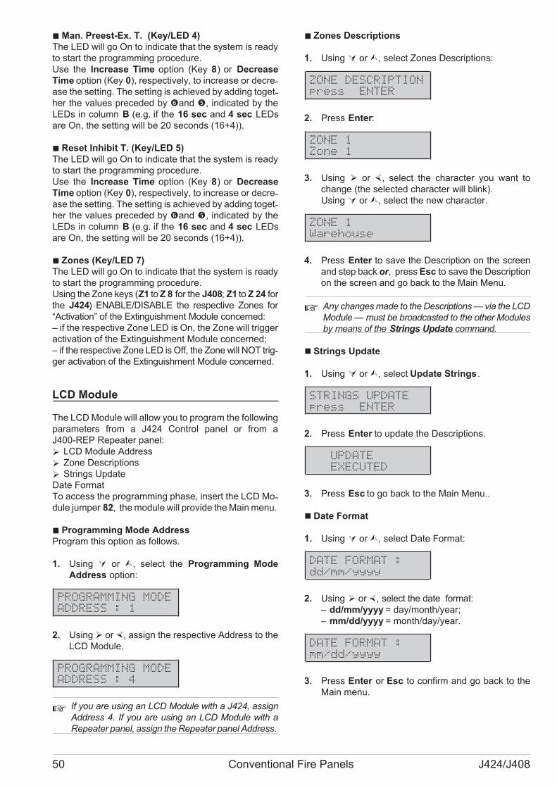
�Man. Preest-Ex. T. (Key/LED 4)
The LED will go On to indicate that the system is ready
to start the programming procedure.
Use the Increase Time option (Key 8) or Decrease
Time option (Key 0), respectively, to increase or decre-ase the setting. The setting is achieved by adding toget-her the values preceded by �and �, indicated by the
LEDs in column B (e.g. if the 16 sec and 4 sec LEDs
are On, the setting will be 20 seconds (16+4)).
� Reset Inhibit T. (Key/LED 5)
The LED will go On to indicate that the system is ready
to start the programming procedure.
Use the Increase Time option (Key 8) or Decrease
Time option (Key 0), respectively, to increase or decre-ase the setting. The setting is achieved by adding toget-her the values preceded by �and �, indicated by the
LEDs in column B (e.g. if the 16 sec and 4 sec LEDs
are On, the setting will be 20 seconds (16+4)).
� Zones (Key/LED 7)
The LED will go On to indicate that the system is ready
to start the programming procedure.
Using the Zone keys (Z1 to Z 8 for the J408; Z1 to Z 24 for
the J424) ENABLE/DISABLE the respective Zones for
“Activation” of the Extinguishment Module concerned:
– if the respective Zone LED is On, the Zone will trigger
activation of the Extinguishment Module concerned;
– if the respective Zone LED is Off, the Zone will NOT trig-ger activation of the Extinguishment Module concerned.
LCD Module
The LCD Module will allow you to program the following
parameters from a J424 Control panel or from a
J400-REP Repeater panel:
� LCD Module Address
� Zone Descriptions
� Strings Update
Date Format
To access the programming phase, insert the LCD Mo-dule jumper 82, the module will provide the Main menu.
� Programming Mode Address
Program this option as follows.
1. Using � or �, select the Programming Mode
Address option:
PROGRAMMING MODE
ADDRESS : 1
2. Using � or �, assign the respective Address to the
LCD Module.
PROGRAMMING MODE
ADDRESS : 4
�If you are using an LCD Module with a J424, assign
Address 4. If you are using an LCD Module with a
Repeater panel, assign the Repeater panel Address.
� Zones Descriptions
1. Using � or�, select Zones Descriptions:
ZONE DESCRIPTION
press ENTER
2. Press Enter:
ZONE 1
Zone 1
3. Using � or �, select the character you want to
change (the selected character will blink).
Using � or�, select the new character.
ZONE 1
Warehouse
4. Press Enter to save the Description on the screen
and step back or, press Esc to save the Description
on the screen and go back to the Main Menu.
� Any changes made to the Descriptions — via the LCD
Module — must be broadcasted to the other Modules
by means of the Strings Update command.
� Strings Update
1. Using � or�, select Update Strings .
STRINGS UPDATE
press ENTER
2. Press Enter to update the Descriptions.
UPDATE
EXECUTED
3. Press Esc to go back to the Main Menu..
� Date Format
1. Using � or�, select Date Format:
DATE FORMAT :
dd/mm/yyyy
2. Using � or�, select the date format:
– dd/mm/yyyy = day/month/year;
– mm/dd/yyyy = month/day/year.
DATE FORMAT :
mm/dd/yyyy
3. Press Enter or Esc to confirm and go back to the
Main menu.
50 Conventional Fire Panels J424/J408
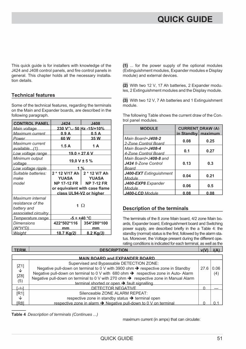
QUICK GUIDE
This quick guide is for installers with knowledge of the
J424 and J408 control panels, and fire control panels in
general. This chapter holds all the necessary installa-tion details.
Technical features
Some of the technical features, regarding the terminals
on the Main and Expander boards, are described in the
following paragraph.
CONTROL PANEL J424 J408
Main voltage 230 V~ 50 Hz -15/+10%
Maximum current 0.9 A 0.5 A
Power 60 W 35 W
Maximum current
available...(1)1.5 A 1 A
Low voltage range 19.0 ÷ 27.6 V
Minimum output
voltage19,0 V ± 5 %
Low voltage ripple 1 %
Suitable batteries:
make
model
2 * 12 V/17 Ah
YUASA
NP 17-12 FR
2 * 12 V/7 Ah
YUASA
NP 7-12 FR
or equivalent with case flame
class UL94-V2 or higher
Maximum internal
resistance of the
battery and
associated circuitry
1 �
Temperature range -5 ÷ +40 °C
Dimensions
(W*H*D)
422*502*116
mm
354*280*100
mm
Weight 18.7 Kg(2) 8.2 Kg(3)
(1) ... for the power supply of the optional modules
(Extinguishment modules, Expander modules e Display
module) and external devices.
(2) With two 12 V, 17 Ah batteries, 2 Expander modu-les, 2 Extinguishment modules and the Display module.
(3) With two 12 V, 7 Ah batteries and 1 Extinguishment
module.
The following Table shows the current draw of the Con-trol panel modules.
MODULE CURRENT DRAW (A)
in Standby maximum
Main Board+J408-2
2-Zone Control Board0.08 0.25
Main Board+J408-4
4-Zone Control Board0.1 0.27
Main Board+J408-8 and
J424 8-Zone Control
Board
0.13 0.3
J400-EXT Extinguishment
Module0.04 0.21
J400-EXP8 Expander
Module0.06 0.5
J400-LCD Module 0.08 0.08
Description of the terminals
The terminals of the 8 zone Main board, 4/2 zone Main bo-ards, Expander board, Extinguishment board and Switching
power supply, are described briefly in the a Table 4: the
standby (normal) status is the first, followed by the alarm sta-tus. Moreover, the Voltage present during the different ope-rating conditions is indicated for each terminal, as well as the
maximum current (in amps) that can circulate:
QUICK GUIDE 51
TERM. DESCRIPTION v(V) i(A)
MAIN BOARD and EXPANDER BOARD
[Z1]
�
[Z8]
(5)
Supervised and Bypassable DETECTION ZONE:
Negative pull-down on terminal to 0 V with 3900 ohm� respective zone in Standby
Negative pull-down on terminal to 0 V with 680 ohm� respective zone in Auto- Alarm
Negative pull-down on terminal to 0 V with 270 ohm� respective zone in Manual Alarm
terminal shorted or open� fault signalling
27.6 0.06
(4)
[M] DETECTOR NEGATIVE 0 —
[R1]
�
[R8]
Silenceable ZONE ALARM REPEAT:
respective zone in standby status� terminal open
respective zone in alarm� Negative pull-down to 0 V on terminal 0 0.1
Table 4 Description of terminals (Continues ...)

(4) The sum of the currents absorbed by terminals [Z1],
[Z2], ..., [Z8], [24V], [24R], [NAC1] and [NAC2] must not
exceed: 1.5 A for the J424 control panel; 1 A for the
J408 control panel.
(5) The terminals [Z1], [Z2], ..., [Z8] and [DL], if not used,
must be connected to negative using a 3900 ohm resistor.
(6) Connect a 3900 ohm resistor between the [+] and [-]
terminals of the NAC1 and NAC2 Outputs, if not used.
TERM. DESCRIPTION v(V) i(A)
2 and 4 ZONE MAIN BOARDS
[DL]
(5)
Supervised—Bypassable DIALLER Output:
during Standby� floating
on expiry of the Alarm Signalling Delay� negative pull-down to 0 V 0 0.1
[OC]
PROGRAMMABLE AUXILIARY Output:
during Standby� terminal floating
on verification of an associated event � negative pull-down to 0 V 0 1
[24V]
[M]
24 V POWER Output:
Positive pull-up to 27.6 V on [24V] terminal
Negative pull-down to 0 V on [M] terminal
27.6
0
1(4)
—
[24R]
[M]
RESETTABLE 24 V POWER Output:
during Standby� positive pull-up to 27.6 V on [24R] terminal
during Reset� [24R] terminal floating;
Negative pull down to 0 V on [M] terminal
27.6
—
0
1(4)
—
—
[PL]
POWER LOSS Output:
during Standby� floating
during power failure� negative pull-down to 0 V
—
0
—
1
ALARM
Non-Supervised—Silenceable ALARM Output:
Control panel in Standby� [COM] terminal connects to [NC] and [NO] floats
Control panel in Alarm� the [COM] and [NO] terminals connect, in accordance with programming — 5
FAULT
Non-Supervised—Silenceable—Bypassable FAULT Output:
Control panel in Standby� [COM] terminal connects to [NC] and [NO] floats
in the event of Fault� [COM] terminal connects to NO] and [NC] floats — 5
NAC1
(6)
Supervised—Silenceable—Bypassable ALARM Output N. 1:
Panel in Standby� negative pull-down to 0 V on [+] terminal; positive pull-up to 27.6 on [–] terminal
Panel in Alarm� positive pull-up to 27.6 on [+] terminal; negative pull-down to 0 V on [–] terminal 27.6 1(4)
NAC2
(6)
Supervised—Silenceable—Bypassable ALARM Output N. 2:
Panel in Standby� negative pull-down to 0 V on [+] terminal; positive pull-up to 27.6 V on [–] terminal
Panel in Alarm� positive pull-up to 27.6 on [+] terminal; negative pull down to 0 V on [–] terminal 27.6 1(4)
8 ZONE MAIN BOARD
RS485
RS485 Serial Port:
Positive pull-up to 27.6 V on [24V] terminal;
Negative pull-down to 0 V on [M] terminal;
data on [+] and [–] terminals
27.6
0
—
1(4)
—
—
Table 4 (...continued) Terminals Description

QUICK GUIDE 53
EXTINGUISHMENT BOARD
EM
Supervised—Bypassable MANUAL EXTINGUISHMENT Input:
3.900 ohm (680 ohm se NC) across [+] and [–] terminals� Input in Standby
680 ohm (3.900 ohm se NC) across [+] and [–] terminals� PRE-EXTINGUISHMENT time
[+] and [–] terminals shorted or open�Manual Extinguishment Fault signalling
— —
IE
Supervised INHIBIT EXTINGUISHMENT Input:
3.900 ohm (680 ohm if NC) across [+] and [–]� Input in Standby
680 ohm (3.900 ohm if NC) across [+] an [–] terminals� EXTINGUISHMENT impossible
[+] and [–] terminals shorted or open� Inhibit Exting. Fault signalling
— —
PS
Supervised PRESSURE SWITCH Input:
3.900 ohm (680 ohm if NC) across [+] and [–] terminals � Input in Standby
680 ohm (3.900 ohm if NC) across [+] and [–] terminals�Pressure Switch Activated signalling
[+] and [–] terminals shorted or open� Pressure Switch Fault signalling
— —
[EV]
Supervised ELECTROVALVE Output:
Extinguishment Module in Standby� terminals disconnected
Extinguishment Module in Extinguishment phase� terminals connected
terminals shorted or open � Electrovalve Fault signalling
— 5
24PPOWER BOOST Input:
Power supply Input for the PR and AE Outputs — —
PR
Supervised PRE-EXTINGUISHMENT Output:
Extinguishment Module in Stand by� negative on [+] terminal, positive on [–] terminal
during the Pre-Extinguishment phase� positive on [+] terminal, negative on [–] terminal
terminals [+] and [–] shorted or open� Fault Pre Ext. signalling
-27.6
27.6
—
1
AE
ACTIVATED EXTINGUISHMENT Output:
Extinguishment Module in Stand by� negative on [+] terminal, positive on [–] terminal
during the Extinguishment phase � positive on [+] terminal, negative on [–] terminal
-27.6
27.6
—
1
PE
POSTPONE EXTINGUISHMENT Output:
IE Input in standby� suspended terminal
IE Input activated � terminal connected to negative 0
—
0.1
Table 4 (...continued) Terminals Description

54 Conventional Fire Panels J424/J408

QUICK GUIDE 55

BENTEL SECURITY s.r.l.
Via Gabbiano, 22 – Zona Ind. S. Scolastica
64013 Corropoli (TE) - ITALY
Tel.: +39 0861 839060
Fax: +39 0861 839065
e-mail: [email protected]
http://www.bentelsecurity.com ISTISBLEJ408-8 2.0 090709 V10
®