Embed Size (px)
Citation preview
Printed in June 2010 Printed inThe United States of America
Blended Ice Machine
Multiplex MS-8-1H, MS-8-EH
Blended Ice MachineMultiplex Models MS-8-1H, MS-8-EHService Manual
Manufactured exclusively forMcDonald’s® By:
Manitowoc FoodserviceTel. (888) 436-5442Tel. (989) 773-7981Fax (888) 779-2040

We reserve the right to make product improvements at any time. Specifications and design are subject to change without notice.
WARNING READ THIS MANUAL THOROUGHLY BEFORE OPERATING, INSTALLING, OR PERFORMING MAINTENANCE ON THE EQUIPMENT.
WARNING FAILURE TO FOLLOW INSTRUCTIONS IN THIS MANUAL CAN CAUSE PROPERTY DAMAGE, INJURY OR DEATH.
WARNING DO NOT STORE OR USE GASOLINE OR OTHER FLAMMABLE VAPORS OR LIQUIDS IN THE VICINITY OF THIS OR ANY OTHER APPLIANCE.
WARNING UNLESS ALL COVER AND ACCESS PANELS ARE IN PLACE AND PROPERLY SECURED, DO NOT OPERATE THIS EQUIPMENT.
WARNING THIS APPLIANCE IS NOT INTENDED FOR USE BY PERSONS WHO LACK EXPERIENCE OR KNOWLEDGE, UNLESS THEY HAVE BEEN GIVEN SUPERVISION OR INSTRUCTION CONCERNING USE OF THE APPLIANCE BY A PERSON RESPONSIBLE FOR THEIR SAFETY.
WARNING THIS APPLIANCE IS NOT TO BE PLAYED WITH.
WARNING DO NOT CLEAN WITH WATER JET.
WARNING DO NOT USE ELECTRICAL APPLIANCES INSIDE THE FOOD STORAGE COMPARTMENT OF THIS APPLIANCE.
CAUTION Observe the following:
• Minimum clearances must be maintained from all walls and combustible materials.
• Keep the equipment area free and clear of combustible material.
• Adequate clearance for air openings.
• Operate equipment only on the type of electricity indicated on the specification plate.
• Retain this manual for future reference.
Important Warning And Safety Information
06/10 3
General InformationModel Numbers . . . . . . . . . . . . . . . . . . . . . . . . . . . . . . . . . . . . . . . . . . . . . . . . . . . . . . . . . . . . 5Serial Number Location . . . . . . . . . . . . . . . . . . . . . . . . . . . . . . . . . . . . . . . . . . . . . . . . . . . . . . 5Warranty Information . . . . . . . . . . . . . . . . . . . . . . . . . . . . . . . . . . . . . . . . . . . . . . . . . . . . . . . . 5Component Identification . . . . . . . . . . . . . . . . . . . . . . . . . . . . . . . . . . . . . . . . . . . . . . . . . . . . . 6Electrical . . . . . . . . . . . . . . . . . . . . . . . . . . . . . . . . . . . . . . . . . . . . . . . . . . . . . . . . . . . . . . . . . 7Clearance Requirements . . . . . . . . . . . . . . . . . . . . . . . . . . . . . . . . . . . . . . . . . . . . . . . . . . . . . 8Heat of Rejection . . . . . . . . . . . . . . . . . . . . . . . . . . . . . . . . . . . . . . . . . . . . . . . . . . . . . . . . . . . 8General Specifications . . . . . . . . . . . . . . . . . . . . . . . . . . . . . . . . . . . . . . . . . . . . . . . . . . . . . . . 8Location . . . . . . . . . . . . . . . . . . . . . . . . . . . . . . . . . . . . . . . . . . . . . . . . . . . . . . . . . . . . . . . . . . 8General Maintenance Instructions . . . . . . . . . . . . . . . . . . . . . . . . . . . . . . . . . . . . . . . . . . . . . . 9Daily Preventive Maintenance Card . . . . . . . . . . . . . . . . . . . . . . . . . . . . . . . . . . . . . . . . . . . . 10Weekly Preventive Maintenance Card . . . . . . . . . . . . . . . . . . . . . . . . . . . . . . . . . . . . . . . . . . 12
OperationHow to Make a Drink . . . . . . . . . . . . . . . . . . . . . . . . . . . . . . . . . . . . . . . . . . . . . . . . . . . . . . . . 17How to Replace a Product Bag . . . . . . . . . . . . . . . . . . . . . . . . . . . . . . . . . . . . . . . . . . . . . . . . 18Shaver Blade Replacement . . . . . . . . . . . . . . . . . . . . . . . . . . . . . . . . . . . . . . . . . . . . . . . . . . . 19Energize Sequence Flowchart . . . . . . . . . . . . . . . . . . . . . . . . . . . . . . . . . . . . . . . . . . . . . . . . . 20Make a Drink Energized Component Flowchart . . . . . . . . . . . . . . . . . . . . . . . . . . . . . . . . . . . 21Rinsing Energized Flowchart . . . . . . . . . . . . . . . . . . . . . . . . . . . . . . . . . . . . . . . . . . . . . . . . . . 24Manager’s Menu Screen . . . . . . . . . . . . . . . . . . . . . . . . . . . . . . . . . . . . . . . . . . . . . . . . . . . . . 26Centering the Scale . . . . . . . . . . . . . . . . . . . . . . . . . . . . . . . . . . . . . . . . . . . . . . . . . . . . . . . . . 26
TroubleshootingDisplay Assembly . . . . . . . . . . . . . . . . . . . . . . . . . . . . . . . . . . . . . . . . . . . . . . . . . . . . . . . . . . 27Blender And Scale . . . . . . . . . . . . . . . . . . . . . . . . . . . . . . . . . . . . . . . . . . . . . . . . . . . . . . . . . . 28Cooling . . . . . . . . . . . . . . . . . . . . . . . . . . . . . . . . . . . . . . . . . . . . . . . . . . . . . . . . . . . . . . . . . . 29Cabinet/Product Thermistors . . . . . . . . . . . . . . . . . . . . . . . . . . . . . . . . . . . . . . . . . . . . . . . . . . 29Ice Shaver/Ice Bin Cover . . . . . . . . . . . . . . . . . . . . . . . . . . . . . . . . . . . . . . . . . . . . . . . . . . . . . 30Product Dispensing . . . . . . . . . . . . . . . . . . . . . . . . . . . . . . . . . . . . . . . . . . . . . . . . . . . . . . . . . 31Rinsing And Water Dispensing . . . . . . . . . . . . . . . . . . . . . . . . . . . . . . . . . . . . . . . . . . . . . . . . 32Refrigeration Operation . . . . . . . . . . . . . . . . . . . . . . . . . . . . . . . . . . . . . . . . . . . . . . . . . . . . . . 33Will Not Run Flowchart . . . . . . . . . . . . . . . . . . . . . . . . . . . . . . . . . . . . . . . . . . . . . . . . . . . . . . 34Weight Beam Diagnostic Flowchart . . . . . . . . . . . . . . . . . . . . . . . . . . . . . . . . . . . . . . . . . . . . . 36Ice Shaver Will Not Run Flowchart . . . . . . . . . . . . . . . . . . . . . . . . . . . . . . . . . . . . . . . . . . . . . 37
Component Check ProceduresON/OFF Rocker Switch . . . . . . . . . . . . . . . . . . . . . . . . . . . . . . . . . . . . . . . . . . . . . . . . . . . . . . 38Transformer . . . . . . . . . . . . . . . . . . . . . . . . . . . . . . . . . . . . . . . . . . . . . . . . . . . . . . . . . . . . . . . 38Control Board Fuse . . . . . . . . . . . . . . . . . . . . . . . . . . . . . . . . . . . . . . . . . . . . . . . . . . . . . . . . . 39IO (Input/Output) Board . . . . . . . . . . . . . . . . . . . . . . . . . . . . . . . . . . . . . . . . . . . . . . . . . . . . . . 39LCD Touchscreen & Microprocessor Control Board . . . . . . . . . . . . . . . . . . . . . . . . . . . . . . . . 40Cabinet Temperature Thermistor . . . . . . . . . . . . . . . . . . . . . . . . . . . . . . . . . . . . . . . . . . . . . . . 40

Table of Contents (continued)
4 06/10
Component Check Procedures, continuedProduct Chase Temperature Thermistor . . . . . . . . . . . . . . . . . . . . . . . . . . . . . . . . . . . . . . . . . 41Chase Fan . . . . . . . . . . . . . . . . . . . . . . . . . . . . . . . . . . . . . . . . . . . . . . . . . . . . . . . . . . . . . . . . 41Evaporator Fan . . . . . . . . . . . . . . . . . . . . . . . . . . . . . . . . . . . . . . . . . . . . . . . . . . . . . . . . . . . . 42Condenser Fan . . . . . . . . . . . . . . . . . . . . . . . . . . . . . . . . . . . . . . . . . . . . . . . . . . . . . . . . . . . . 42Ice Bin Lid Microswitch . . . . . . . . . . . . . . . . . . . . . . . . . . . . . . . . . . . . . . . . . . . . . . . . . . . . . . 42Product Pump . . . . . . . . . . . . . . . . . . . . . . . . . . . . . . . . . . . . . . . . . . . . . . . . . . . . . . . . . . . . . 43Solenoid Valves . . . . . . . . . . . . . . . . . . . . . . . . . . . . . . . . . . . . . . . . . . . . . . . . . . . . . . . . . . . . 43Shaver Motor . . . . . . . . . . . . . . . . . . . . . . . . . . . . . . . . . . . . . . . . . . . . . . . . . . . . . . . . . . . . . . 43Circuit Breaker . . . . . . . . . . . . . . . . . . . . . . . . . . . . . . . . . . . . . . . . . . . . . . . . . . . . . . . . . . . . . 44Blender Motor . . . . . . . . . . . . . . . . . . . . . . . . . . . . . . . . . . . . . . . . . . . . . . . . . . . . . . . . . . . . . 44Manual Rinse Push Button . . . . . . . . . . . . . . . . . . . . . . . . . . . . . . . . . . . . . . . . . . . . . . . . . . . 44Compressor Electrical Diagnostics . . . . . . . . . . . . . . . . . . . . . . . . . . . . . . . . . . . . . . . . . . . . . 45Discharge Pressure High Checklist . . . . . . . . . . . . . . . . . . . . . . . . . . . . . . . . . . . . . . . . . . . . . 46Discharge Pressure Low Checklist . . . . . . . . . . . . . . . . . . . . . . . . . . . . . . . . . . . . . . . . . . . . . 46Suction Pressure High Checklist . . . . . . . . . . . . . . . . . . . . . . . . . . . . . . . . . . . . . . . . . . . . . . . 46Suction Pressure Low Checklist . . . . . . . . . . . . . . . . . . . . . . . . . . . . . . . . . . . . . . . . . . . . . . . 46Recovery/Evacuation . . . . . . . . . . . . . . . . . . . . . . . . . . . . . . . . . . . . . . . . . . . . . . . . . . . . . . . . 47
Assembly & Replacement Parts ListBase . . . . . . . . . . . . . . . . . . . . . . . . . . . . . . . . . . . . . . . . . . . . . . . . . . . . . . . . . . . . . . . . . . . . 48Top . . . . . . . . . . . . . . . . . . . . . . . . . . . . . . . . . . . . . . . . . . . . . . . . . . . . . . . . . . . . . . . . . . . . . . 49Miscellaneous . . . . . . . . . . . . . . . . . . . . . . . . . . . . . . . . . . . . . . . . . . . . . . . . . . . . . . . . . . . . . 49Duct Outlet . . . . . . . . . . . . . . . . . . . . . . . . . . . . . . . . . . . . . . . . . . . . . . . . . . . . . . . . . . . . . . . . 50Door . . . . . . . . . . . . . . . . . . . . . . . . . . . . . . . . . . . . . . . . . . . . . . . . . . . . . . . . . . . . . . . . . . . . . 50Top Valve & Pump . . . . . . . . . . . . . . . . . . . . . . . . . . . . . . . . . . . . . . . . . . . . . . . . . . . . . . . . . . 51Lower Pump . . . . . . . . . . . . . . . . . . . . . . . . . . . . . . . . . . . . . . . . . . . . . . . . . . . . . . . . . . . . . . 51VitaMix Assembly . . . . . . . . . . . . . . . . . . . . . . . . . . . . . . . . . . . . . . . . . . . . . . . . . . . . . . . . . . 51Condensing Unit . . . . . . . . . . . . . . . . . . . . . . . . . . . . . . . . . . . . . . . . . . . . . . . . . . . . . . . . . . . 52Evaporator Coil . . . . . . . . . . . . . . . . . . . . . . . . . . . . . . . . . . . . . . . . . . . . . . . . . . . . . . . . . . . . 52
Refrigerant Recovery/Evacuation & Charging ProceduresCharging Procedures . . . . . . . . . . . . . . . . . . . . . . . . . . . . . . . . . . . . . . . . . . . . . . . . . . . . . . . . 53System Contamination Cleanup . . . . . . . . . . . . . . . . . . . . . . . . . . . . . . . . . . . . . . . . . . . . . . . 53Mild System Contamination Cleanup Procedure . . . . . . . . . . . . . . . . . . . . . . . . . . . . . . . . . . . 54Severe System Contamination Cleanup Procedure . . . . . . . . . . . . . . . . . . . . . . . . . . . . . . . . 55Filter-Driers . . . . . . . . . . . . . . . . . . . . . . . . . . . . . . . . . . . . . . . . . . . . . . . . . . . . . . . . . . . . . . . 55Total System Refrigerant Charge . . . . . . . . . . . . . . . . . . . . . . . . . . . . . . . . . . . . . . . . . . . . . . 55Operating Pressures Chart . . . . . . . . . . . . . . . . . . . . . . . . . . . . . . . . . . . . . . . . . . . . . . . . . . . 55
Specifications/Wiring Diagrams/SchematicsMS-8-1H Wiring Diagram . . . . . . . . . . . . . . . . . . . . . . . . . . . . . . . . . . . . . . . . . . . . . . . . . . . . 56MS-8-EH Wiring Diagram . . . . . . . . . . . . . . . . . . . . . . . . . . . . . . . . . . . . . . . . . . . . . . . . . . . . 57Blender Scale & Shaver Schematics . . . . . . . . . . . . . . . . . . . . . . . . . . . . . . . . . . . . . . . . . . . . 58Electronic Control Board . . . . . . . . . . . . . . . . . . . . . . . . . . . . . . . . . . . . . . . . . . . . . . . . . . . . . 59

06/10 5
Model NumbersThis manual covers the Blended Ice Machine, model numbers MS-8-1H and MS-8-EH.
Serial Number LocationThis number is required when requesting information from your local distributor. The serial number is listed on the SERIAL NUMBER DECAL affixed to the middle of the lower back panel on the Blended Ice Machine. A second decal is located on the front right side of cup dispenser.
General Warranty InformationYour Blended Ice Machine comes with a three-year warranty on parts and labor and a five-year warranty on compressor. Consult your local Multiplex Distributor for terms and conditions of your warranty. Your warranty specifically excludes all general adjustments, cleaning, accessories and related servicing.
The warranty card must be returned to activate the warranty on this equipment. If a warranty card is not returned, the warranty period can begin when the equipment leaves the Multiplex factory.
No equipment may be returned to without a written Return Materials Authorization (RMA). Equipment returned without an RMA will be refused at dock and returned to the sender at the sender’s expense.
Please contact your local distributor for return procedures.
The following Warranty outline is provided for your convenience. For a detailed explanation, read the warranty bond shipped with each product.
Contact your local Multiplex representative or Multiplex if you need further warranty information.
PARTS
Multiplex warrants the Blended Ice Machine against defects in materials and workmanship, under normal use and service for three (3) years from the date of original installation.
The evaporator and compressor are covered by an additional two (2) year (five years total) warranty beginning on the date of the original installation.
LABOR
Labor required to repair or replace defective components is covered for three (3) years from the date of original installation.
EXCLUSIONS
The following items are not included in the Blended Ice Machine warranty coverage:
Normal maintenance, adjustments and cleaning as outlined in this manual.
Repairs due to unauthorized modifications to the Blended Ice Machine or use of non-standard parts without prior written approval from Multiplex.
Damage caused by improper installation of the Blended Ice Machine, electrical supply, water supply or drainage, or damage caused by floods, storms, or other acts of God.
Premium labor rates due to holidays, overtime, etc.; travel time; flat rate service call charges; mileage and miscellaneous tools and material charges not listed on the payment schedule. Additional labor charges resulting from the inaccessibility of equipment are also excluded.
Parts or assemblies subjected to misuse, abuse, neglect or accidents.
Damage or problems caused by installation, cleaning and/or maintenance procedures inconsistent with the technical instructions provided in this manual.
Authorized Warranty Service
To comply with the provisions of the warranty, a refrigeration service company qualified and authorized by your Multiplex Distributor, or a Contracted Service Representative must perform the warranty repair.
SERVICE CALLS
Normal maintenance, adjustments and cleaning as outlined in this manual are not covered by the warranty. If you have followed the procedures listed in this manual, and the Blended Ice Machine still does not perform properly, call your Local Distributor or the Multiplex Service Department.
General Information

6 06/10
Component Identification
General System OverviewThe Blended Ice Machine is a self-contained dispensing unit that allows the operator to make flavor combinations of blended ice drinks. It contains product flavoring in a reach-in enclosure, a refrigeration system and an ice shaving machine.
The operator controls and accesses the unit using a lighted touch screen. Icons on the Drink Selection screen represent the primary flavor combinations for the blended ice drinks. A second screen provides drink size options (S, M, L) and ingredient options, such as “no yogurt.” Menu changes and additions are uploaded using a USB mass storage device.
On-screen instructions also include operator procedures for cleaning/sanitizing, checking inventory, replacing product bags, selecting drink sizes and manually preparing drinks. Managers and technicians have access to menu/software updates, diagnostics and other service screens.
Part Description Number
Blender Fill Pitcher 3239630Cleaning Kit 000-BIC-0008Cleaning Pitcher 3239631Cup Dispenser 1706175Gasket, Door 1706208Gasket, Whipped Cream Door 1706209Hinge Kit RF000066Ice Hopper Lid VMP00133Lid Dispenser 1706142Product Bin 1706267Pull Out Tray 076-CDZ-0000Syrup Rail 1706194Syrup Rail Divider 1706195Whipped Cream Door 000-187-0016
Cup Dispenser
(1706175)
Touch Screen
Manual Rinse Button
Blender Rinse Location
Product Bins
(1706267)
Pull Out Tray
(076-CDZ-0000)
Blender Fill Pitcher
(3239630)
Lid Dispenser
(1706142)
Ice Hopper Lid
(VMP00133)
Whipped Cream Door
(000-187-0016)
Syrup Rail
(1706194)
Syrup Rail Divider
(1706195)

06/10 7
Electrical
GENERAL
! WarningAll wiring must conform to local, state and national codes.
MINIMUM CIRCUIT AMPACITY
The minimum circuit ampacity is used to help select the wire size of the electrical supply. (Minimum circuit ampacity is not the Blended Ice Machine’s running amp load.) The wire size (or gauge) is also dependent upon location, materials used, length of run, etc., so it must be determined by a qualified electrician.
ELECTRICAL REQUIREMENTS
Refer to Blended Ice Machine Model/Serial Plate for voltage/amperage specifications.
VOLTAGE
The standard voltage is 120VAC-60Hz. A power cord is provided with a NEMA 5-20P electrical plug. A dedicated electrical circuit is required.
NEMA 5-20P Plug Configuration
MINIMUM CIRCUIT AMPERAGE CHART
ImportantDue to continuous improvements, this information is for reference only. Please refer to the serial number tag to verify electrical data. Serial tag information overrides information listed on this page.
Model Numbers
Voltage/CycleTotal Amps
Breaker Size
MS-8-1H 8 flavor
115/60/1 16.0 20A
MS-8-EH 8 flavor
230-240/50/1 9.8 16A
GROUNDING INSTRUCTIONS
! WarningThe machine must be grounded in accordance with national and local electrical codes.
This appliance must be grounded. In the event of malfunction or breakdown, grounding provides a path of least resistance for electric current to reduce the risk of electric shock. This appliance is equipped with a cord having an equipment-grounding conductor and a grounding plug. The plug must be plugged into an appropriate outlet that is properly installed and grounded in accordance with all local codes and ordinances.
EXPORT NOTE: For export models replace the supply cord with a 1.5mm2 minimum, 3 conductor H05VV-F harmonized cord.
8 06/10
Clearance Requirements
Model Air Cooled
Top 8" (20 cm)
Sides 6" (15 cm)
Back 6" (15 cm)
Front 30" (76 cm)
Heat of Rejection
ModelHeat of Rejection
Air Conditioning Peak
MS-8-1H 2100 2600
MS-8-EH 2100 2600
General Specifications
Temperature Control Setting 36°F setpoint 4°F differential 2°C setpoint 2°C differential
controlled by software
Ice Capacity 23 lbs (10 kg)
Shipping Weight 430 lbs (195 kg)
Product Bin Capacity 19.8lbs (9kg) per bin
CO2 Regulator Setting 40lbs
Water Regulator Setting 30lbs
LocationThe location selected for the Blended Ice Machine must meet the following criteria.
The air temperature must be at least 40°F (4°C), but must not exceed 90°F (32°C), climate class 4.
The location must not be near heat-generating equipment or in direct sunlight and must be protected from weather.
Water temperature min/max = 40°F/110°F (4°C/43°C).
Water pressure min/max = 20 psi/40 psi (138kPa/276kPa)
Always use the water supply line supplied when installing this appliance. Never reuse an old supply line.
Main supply CO2 pressure to Blended Ice Machine
regulator min/max = 100 psi/150 psi (689kPa/1034kPa)
! WarningCarbon Dioxide (CO
2) displaces oxygen. Exposure
to a high concentration of CO2 gas causes tremors,
which are followed rapidly by loss of consciousness and suffocation. If a CO
2 gas leak is suspected,
particularly in a small area, immediately ventilate the area before repairing the leak. CO
2 lines and
pumps must not be installed in an enclosed space. An enclosed space can be a cooler or small room or closet. This may include convenience stores with glass door self serve coolers. If you suspect CO
2
may build up in an area, venting of the B-I-B pumps and / or CO
2 monitors must be utilized.
•
•
•
•
•
•

06/10 9
Maintenance
Door Gasket Maintenance
Door gaskets require regular cleaning to prevent mold and mildew build up and also to retain the elasticity of the gasket. Gasket cleaning can be done with the use of warm soapy water. Avoid full strength cleaning products on gaskets as this can cause them to become brittle and crack. Never use sharp tools or knives to scrape or clean the gasket. Gaskets can be easily replaced and do not require the use of tools or an authorized service person. The gaskets are “Dart” style and can be pulled out of the groove in the door and new gaskets can be “pressed” back into place.
Drain Maintenance - Base
Each unit has a drain located inside the unit that removes the condensation from the evaporator coil and routes it to an external condensate evaporator pan. Each drain can become loose or disconnected during normal use. If you notice water accumulation on the inside of the unit be sure the drain tube is connected to the evaporator drain pan. If water is collecting underneath the unit make sure the end of the drain tube is in the condensate evaporator in the machine compartment. The leveling of the unit is important as the units are designed to drain properly when level. Be sure all drain lines are free of obstructions.
Caster Maintenance
Wipe casters with a damp cloth monthly to prevent corrosion.
The power switch must be turned to OFF and the unit disconnected from the power source whenever performing service, maintenance functions or cleaning the refrigerated area.
Refrigerators
The interior and exterior can be cleaned using soap and warm water. If this isn’t sufficient, try ammonia and water or a nonabrasive liquid cleaner. When cleaning the exterior, always rub with the “grain” of the stainless steel to avoid marring the finish. Do not use an abrasive cleaner because it will scratch the stainless steel and can damage the breaker strips and gaskets.
Stainless Steel Care and Cleaning
To prevent discoloration or rust on stainless steel several important steps need to be taken. First, we need to understand the properties of stainless steel. Stainless steel contains 70- 80% iron, which will rust. It also contains 12-30% chromium, which forms an invisible passive film over the steel’s surface, which acts as a shield against corrosion. As long as the protective layer is intact, the metal is still stainless. If the film is broken or contaminated, outside elements can begin to breakdown the steel and begin to form discoloration or rust. Proper cleaning of stainless steel requires soft cloths or plastic scouring pads.
NEVER USE STEEL PADS, WIRE BRUSHES OR SCRAPERS!
Cleaning solutions need to be alkaline based or non-chloride cleaners. Any cleaner containing chlorides will damage the protective film of the stainless steel. Chlorides are also commonly found in hard water, salts, and household and industrial cleaners. If cleaners containing chlorides are used be sure to rinse repeatedly and dry thoroughly. Routine cleaning of stainless steel can be done with soap and water. Extreme stains or grease should be cleaned with a non-abrasive cleaner
and plastic scrub pad. Always rub with the grain of the steel. There are stainless steel cleaners available which can restore and preserve the finish of the steels protective layer. Early signs of stainless steel breakdown are small pits and cracks. If this has begun, clean thoroughly and start to apply stainless steel cleaners in attempt to restore the passivity of the steel.
Never use an acid based cleaning solution! Many food products have an acidic content, which can deteriorate the finish. Be sure to clean the stainless steel surfaces of ALL food products. Common items include, tomatoes, peppers and other vegetables.
Cleaning the Condenser Coil
In order to maintain proper refrigeration performance, the condenser fins must be cleaned of dust, dirt and grease regularly. It is recommended that this be done at least every three months. If conditions are such that the condenser is totally blocked in three months, the frequency of cleaning should be increased. Clean the condenser with a vacuum cleaner or stiff brush. If extremely dirty, a commercially available condenser cleaner may be required.
Failure to maintain a clean condenser coil can initially cause high temperatures and excessive run times. Continuous operation with a dirty or clogged condenser coil can result in compressor failure. Neglecting the condenser coil cleaning procedures will void any warranties associated with the compressor and cost to replace the compressor.
Never use a high-pressure water wash for this cleaning procedure as water can damage the electrical components located near or at the condenser coil.
Doors/Hinges
Over time and with heavy use doors the hinges may become loose. If this happens tighten the screws that mount the hinge brackets to the frame of the unit. Loose or sagging doors can cause the hinges to pull out of the frame, which may damage both the doors and the hinges. In some cases this may require qualified service agents or maintenance personnel to perform repairs.
Do not place hot pans on/against the blue ABS liner. Do not throw items into the storage area. Failure to follow these recommendations could result in damage to the interior of the cabinet or to the blower coil. Overloading the storage area, restricting the airflow, and continuous opening and closing of the doors and drawers will hamper the units ability to maintain operational temperature.
Preventing blower coil corrosion
To help prevent corrosion of the blower coil, store all acidic items, such as pickles and tomatoes, in sealable containers. Immediately wipe up all spills.
Continuous opening and closing of the doors will hamper the unit’s ability to maintain optimum refrigeration temperature. Top section is not intended for overnight storage. Product should be removed from pans. Pans can remain in unit while empty.

10 06/10
Clean Blended Ice Machine (BIM-8) Daily BE 23 D1
©McDonald’s Corporation · Planned Maintenance Manual · June 2010 Page 1 of 2
Blended Ice Machine Models MS-8-1H, MS-8-EH Daily
BE 23 D1 Why To break the bacteria cycle
Time required 5 minutes to prepare 15 minutes to complete
Time of day At close For 24-hour restaurants: During low-volume periods
Hazard icons
Precaution: Hazard Communication Standard (HCS) – The procedures on this card include the use of chemical products. These chemical products will be highlighted with bold face letters followed by the abbreviation (HCS) in the tools portion of the procedure. See the Hazard Communication Standard (HCS) manual for the appropriate Material Safety Data Sheet(s) (MSDS).
Tools and supplies
Bucket, clean and sanitized towels
Scoop Bucket, soiled towels KAY 5 Sanitizer solution (HCS)
KAY Beverage Equipment Cleaner
No-Scratch Pad
Procedure
1 Cycle touch pad to cleaning. On the Menu Screen press Cleaning, then Daily Cleaning.
2 Gather items shown.
3 Empty ice hopper. Remove ice hopper lid. Use an ice scoop and an empty bucket to remove as much ice as possible from above the ice shelf. Replace ice hopper lid.
4 Manually dispense ice. Place a blend pitcher on the pitcher pad. Press Manual Ice Dispense button until ice hopper is empty. Remove blender pitcher of ice and discard in back sink.
5 Remove parts for cleaning and sanitizing. Remove the following items and take them back to the 3 compartment sink to wash, rinse and sanitize.
Blender pitchers Ice hopper lid Syrup rail Drip pan Splash guard
Do not place parts in “Power Soaker” or dishwasher.
Chemicals
continued

06/10 11
Clean Blended Ice Machine (BIM-8) (continued)
©McDonald’s Corporation · Planned Maintenance Manual · June 2010 Page 2 of 2
Blended Ice Machine Models MS-8-1H, MS-8-EH Daily
BE 23 D1
6 With the blender pitchers at the 3-compartment sink, clean pitchers. Place one KAY Beverage Equipment Cleaner packet into the first pitcher and fill with hot water from the back sink. Allow the product to soak in the pitcher for 5 minutes. Use a no-scratch pad to remove any film build-up. Pour the solution into the second pitcher and soak for 5 minutes. Once this is done, discard solution, rinse and sanitize both pitchers in the 3-compartment sink. Allow to air dry.
KAY Beverage Equipment Cleaner
7 Sanitize ice chute Use a spray bottle with Sanitizer solution and a sanitized towel to sanitize:
Above and around the ice chute
Inside the ice chute
KAY 5 Sanitizer
8 Clean pitcher pad and drain area.
Use coffee pot of hot water from the back sink to rinse drain area and drain.
Spray the drain area with Sanitizer solution and wipe with a clean sanitize towel.
Clean top and sides of the pad.
KAY 5 Sanitizer
9 Re-install all components. Blend pitchers, ice hopper lid, syrup rails, drip pan and splash guard.
10 Clean with APSC the interior of the blended ice machine with a clean, sanitized towel dampened with KAY 5 Sanitizer solution:
Clean inside the machine.
Pull out the whipped cream holder and clean the holder and sides inside the machine that hold the holder
Clean all door gaskets
KAY 5 Sanitizer
11 Clean with APSC the exterior of the blended ice machine with a clean, sanitized towel dampened with KAY 5 Sanitizer solution:
Clean lid holders, cup holder tubes, cabinet, front of door, top of work surface, touch screen, outside of ice hopper
KAY 5 Sanitizer
12 06/10
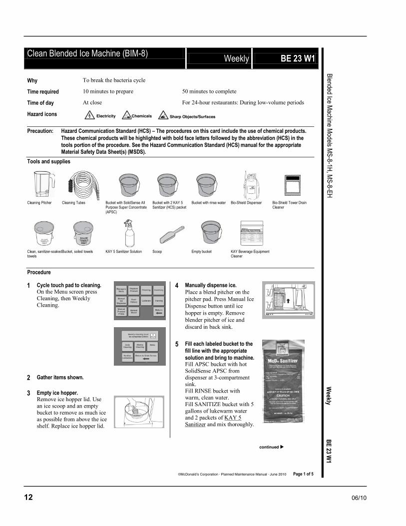
Clean Blended Ice Machine (BIM-8) Weekly BE 23 W1
©McDonald’s Corporation · Planned Maintenance Manual · June 2010 Page 1 of 5
Blended Ice Machine Models MS-8-1H, MS-8-EH W
eekly BE 23 W
1 Why To break the bacteria cycle
Time required 10 minutes to prepare 50 minutes to complete
Time of day At close For 24-hour restaurants: During low-volume periods
Hazard icons
Precaution: Hazard Communication Standard (HCS) – The procedures on this card include the use of chemical products. These chemical products will be highlighted with bold face letters followed by the abbreviation (HCS) in the tools portion of the procedure. See the Hazard Communication Standard (HCS) manual for the appropriate Material Safety Data Sheet(s) (MSDS).
Tools and supplies
Cleaning Pitcher Cleaning Tubes Bucket with SolidSense All
Purpose Super Concentrate (APSC)
Bucket with 2 KAY 5 Sanitizer (HCS) packet
Bucket with rinse water Bio-Shield Dispenser Bio-Shield Tower Drain Cleaner
Clean, sanitizer-soaked towels
Bucket, soiled towels KAY 5 Sanitizer Solution Scoop Empty bucket KAY Beverage Equipment Cleaner
Procedure
1 Cycle touch pad to cleaning. On the Menu screen press Cleaning, then Weekly Cleaning.
2 Gather items shown.
3 Empty ice hopper. Remove ice hopper lid. Use an ice scoop and an empty bucket to remove as much ice as possible from above the ice shelf. Replace ice hopper lid.
4 Manually dispense ice. Place a blend pitcher on the pitcher pad. Press Manual Ice Dispense button until ice hopper is empty. Remove blender pitcher of ice and discard in back sink.
5 Fill each labeled bucket to the fill line with the appropriate solution and bring to machine. Fill APSC bucket with hot SolidSense APSC from dispenser at 3-compartment sink. Fill RINSE bucket with warm, clean water. Fill SANITIZE bucket with 5 gallons of lukewarm water and 2 packets of KAY 5 Sanitizer and mix thoroughly.
Electricity Chemicals Sharp Objects/Surfaces
continued

06/10 13
Clean Blended Ice Machine (BIM-8) (continued)
©McDonald’s Corporation · Planned Maintenance Manual · June 2010 Page 2 of 5
Blended Ice Machine Models MS-8-1H, MS-8-EH W
eekly BE 23 W
1
6 Remove product bins and bags. Remove each product bag from the product bin and place in walk-in cooler. Take product bins to 3-compartment sink and wash, rinse and sanitize. Allow to air dry.
7 Connect cleaning tubes. Connect one tube from the cleaning tubes to each inlet line. Insert the free end of the tubes into the bucket of clean SolidSense APSC solution. All lines must be cleaned including unused.
SolidSense APSC solution
8 Place black cleaning pitcher on pitcher pad.
9 Press Next. The message window will display: “APSC cleaning of Strawberry Banana Line”, then change to the next flavor until all lines have been cleaned. If cleaner solution runs low, press Pause, refill the bucket with cleaner solution and press Resume. After the last line is cleaned, the next cleaning screen will appear.
10 Remove tubes from the APSC bucket and place into the warm water RINSE bucket.
11 Press Next. The message window will display: “Rinse of Strawberry Banana Line”, then change to the next flavor until all lines have been rinsed. If water runs low, press Pause, refill the bucket with warm water and press Resume. After the last line is cleaned, the next cleaning screen will appear.
12 Remove tubes from RINSE bucket and place into the warm water SANITIZE bucket.
KAY 5 Sanitizer
13 Press Next. The message window will display: “Sanitizer fill of Strawberry Banana Line”, then change to the next flavor until all lines have been sanitized. If sanitizer solution runs low, press Pause, refill the bucket with sanitizer solution and press Resume.
14 Sanitize Hold After the last line is sanitized, “Sanitize Hold” will appear, and then the next cleaning screen will appear.
15 Remove tubes from Sanitize solution and lay across the top rim of the bucket.
16 Press Next. The message window will display: “Auto purge of Strawberry Banana Line”, then change to the next flavor until all lines have been purged. The next cleaning screen will appear.
17 Disconnect the cleaning tubes from each product line.
Chemicals
continued
Chemicals

14 06/10
Clean Blended Ice Machine (BIM-8) (continued)
©McDonald’s Corporation · Planned Maintenance Manual · June 2010 Page 3 of 5
Blended Ice Machine Models MS-8-1H, MS-8-EH W
eekly BE 23 W
1 18 Pull the bottom drain pan from
inside the machine.
19 Reconnect product bins and bags. Retrieve product bags from walk-in cooler. Install product bags into the product bins. Position the rear groove of the spout on the product bag into the front slot of the product bin. Make sure it’s properly snapped into place. Then install each product bin into its proper location.
20 Replace black cleaning pitcher with blending pitcher. Place discharged product in trash or back sink.
21 Remove Ice hopper lid.
22 Place black cleaning pitcher on the pitcher pad.
23 Fill a blend pitcher with SolidSense APSC.
SolidSense APSC
24 Pour in SolidSense APSC. Slowly pour the SolidSense APSC into the ice hopper in a circular motion, as close to and as high up the inside walls as possible, without splashing solution outside the unit.
25 Use clean sanitizer-soaked towel to clean inside of hopper. Use caution when wiping near the shaver blade.
26 Rinse ice hopper with clean water. Fill a blend pitcher with clean water. Slowly pour the clean water into the ice hopper in a circular motion, as close to and as high up the inside walls as possible, without splashing outside the unit. Repeat if needed for a thorough rinse.
27 Remove black cleaning pitcher from the pitcher pad, be careful not to splash any remaining solution from the pitcher.
28 Spray interior of ice hopper with Sanitizer Solution. Allow to air dry.
Use caution when near the shaver blade.
KAY 5 Sanitizer
29 Remove parts for cleaning and sanitizing. Remove the following items and take them back to the 3-compartment sink to wash, rinse and sanitize:
Blend pitchers Ice hopper lid Syrup rail Drip pan Splash guard
Do not place parts in “Power Soaker” or dishwasher.
Chemicals
Sharp Objects/Surfaces
Sharp Objects/Surfaces
continued

06/10 15
Clean Blended Ice Machine (BIM-8) (continued)
©McDonald’s Corporation · Planned Maintenance Manual · June 2010 Page 4 of 5
Blended Ice Machine Models MS-8-1H, MS-8-EH W
eekly BE 23 W
1
30 With the blender pitchers at the 3-compartment sink: Place one KAY Beverage Equipment Cleaner packet into the first pitcher and fill with hot water from the back sink. Allow the product to soak in the pitcher for 5 minutes. Use a no-scratch pad to remove any film build-up. Pour the solution into the second pitcher and soak for 5 minutes. Once this is done, discard solution and rinse and sanitize both pitchers in the 3-compartment sink. Allow to air dry.
KAY Beverage Equipment Cleaner
31 Sanitize ice chute Use a spray bottle with Sanitizer solution and a sanitized towel to sanitize:
Above and around the ice chute
Inside the ice chute
KAY 5 Sanitizer
32 Clean pitcher pad and drain area.
Use coffee pot of hot water from the back sink to rinse drain area and drain.
Spray the drain area with Sanitizer solution and wipe with a clean sanitize towel.
Clean top and sides of the pad.
KAY 5 Sanitizer
33 Re-install all components. Blend pitchers, ice hopper lid, syrup rails, drip pan and splash guard.
34 Clean with APSC the interior of the blended ice machine with a clean, sanitized towel dampened with KAY 5 Sanitizer solution:
Clean inside the machine.
Pull out the whipped cream holder and clean the holder and sides inside the machine that hold the holder
Clean all door gaskets
KAY 5 Sanitizer
35 Clean with APSC the exterior of the blended ice machine with a clean, sanitized towel dampened with KAY 5 Sanitizer solution:
Clean lid holders, cup holder tubes, cabinet, front of door, top of work surface, touch screen, outside of ice hopper
KAY 5 Sanitizer
36 Slowly pour two full pitchers of hot water from the back sink into the rinse area.
37 On top of the BIO-SHIELD® dispenser open the pressure relief knob by turning the knob counter clockwise.
38 Remove the cap from the BIO-SHIELD® dispenser.
continued

16 06/10
Clean Blended Ice Machine (BIM-8) (continued)
©McDonald’s Corporation · Planned Maintenance Manual · June 2010 Page 5 of 5
Blended Ice Machine Models MS-8-1H, MS-8-EH W
eekly BE 23 W
1 39 Pour two full pitchers of hot
water from the back sink into the dispenser.
40 Quickly pour one packet of BIO-SHIELD Beverage Tower Drain Cleaner into the dispenser. Immediately replace and tighten the cap. Then on top of the BIO-SHIELD® dispenser close the pressure relief knob by turning the knob clockwise. Shake the dispenser to dissolve the cleaner.
Drain Cleaner.
41 Carefully purge a small amount of solution from the dispenser into the back sink or utility sink. This helps prevent “sputtering” of solution and possible splashing back onto clothing or eyes.
42 Carefully spray the solution into the rinser sink drain hole.
43 Open the pressure relief knob again by turning the knob counter clockwise on top of the BIO-SHIELD® dispenser.
44 Remove the cap from the BIO-SHIELD® dispenser.
45 Rinse the BIO-SHIELD® dispenser. Rinse the BIO-SHIELD® dispenser with warm water and return the dispenser to the proper storage area. IMPORTANT! Do not use the drain for at least four hours after cleaning. But the machine can still be used.

06/10 17
Procedure to Make a DrinkNOTE: Ice must be present in the ice bin and product must be connected and primed to produce a drink.
Drink Selection Touch Screen
1. Place a clean blend container on the container pad.
2. Press the touch screen to select the type of drink desired from list of main menu items. The screen will advance and list the selection. (If the selection is incorrect, press return and reselect).
Size and Option Touch Screen
3. Select drink options:
- Select Return to view the previous screen.
- The yogurt button toggles between including and leaving out the yogurt.
- Select the Multiple button if you want to make multiple drinks of the same flavor.
- Select drink size(s).
NOTE: A green box will highlight the selections.
4. The machine will add the proper amount of ingredients, blend and stop automatically.
5. Pour the drink into a properly sized cup for the drink selection.
6. Place container in rinse position – container is automatically rinsed.
Operation
18 06/10
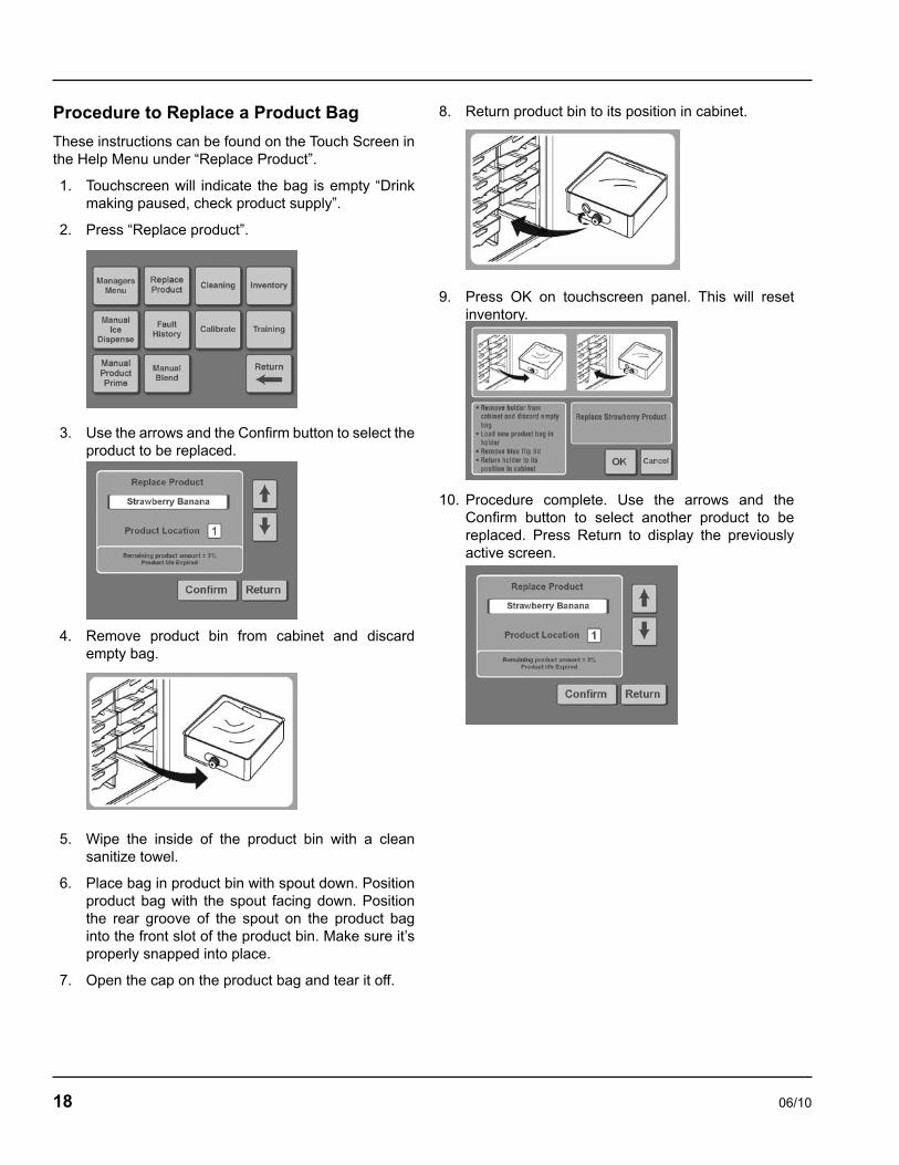
Procedure to Replace a Product Bag
These instructions can be found on the Touch Screen in the Help Menu under “Replace Product”.
Touchscreen will indicate the bag is empty “Drink making paused, check product supply”.
Press “Replace product”.
Use the arrows and the Confirm button to select the product to be replaced.
Remove product bin from cabinet and discard empty bag.
Wipe the inside of the product bin with a clean sanitize towel.
Place bag in product bin with spout down. Position product bag with the spout facing down. Position the rear groove of the spout on the product bag into the front slot of the product bin. Make sure it’s properly snapped into place.
Open the cap on the product bag and tear it off.
1.
2.
3.
4.
5.
6.
7.
Return product bin to its position in cabinet.
Press OK on touchscreen panel. This will reset inventory.
Procedure complete. Use the arrows and the Confirm button to select another product to be replaced. Press Return to display the previously active screen.
8.
9.
10.

06/10 19
Shaver Blade ReplacementWARNING: To reduce the risk of injury, unplug the unit before beginning any repair or upgrade work.
WARNING: Shaver and Blender Blades are sharp! Handle with caution to avoid injury.
NOTE: Actual components may differ slightly in appearance from those shown in this Update.
Unplug the unit from its power source.
Remove the Lid and the Ice Shelf from the Ice Bin.
Remove the Shaver Wheel. To do so, hold the Shaver Wheel firmly with one hand while turning the Paddle nut counterclockwise with the other hand, as shown in Figure A. If the Paddle Nut is too tight to loosen by hand, use a pair of pliers. After removing the Paddle Nut, pull the Shaver Wheel up and off of the shaft.
The Ice Shaver Blade should now be exposed. Remove the two screws that secure the blade, as shown in Figure B. Note that the screw holes in the Shaver blade are recessed to allow the mounting screws to fit flush with the top surface of the blade. When installing the new Shaver Blade, be sure to mount it with the recessed side facing upward. Also note the number and type of shims underneath the blade (See Figure C.). The two different types of shims are easily distinguishable by their thickness. There may be a number of different shim combinations based on the vintage of your unit, including but not limited to one thin shim alone, one thick shim alone and one thick shim in combination with up to five thin shims. Be sure to note this accurately when you remove the blade.
The Ice Shaver Blade Replacement Kit, shown in Figure D, includes:
(1) Shaver Blade (STM519) NOTE: The replacement Shaver Blade may differ in appearance from the blade currently installed.
(1) Thick Shim (STM517)
(4) Thin Shims (STM514)
(2) Mounting Screws (FST527) NOTE: Mounting Screws may be a different length than the screws that you currently use.
Replace the old blade with the blade from the kit, along with the same combination of shims that existed when you removed the old blade. You can reuse the old shims or use the shims provided in the kit as long as the combination is the same as the original. Be sure to mount the blade so that the side with recessed screw holes is facing up.
Secure the new blade with the new screws provided. The new screws should be compatible with any shim configuration even if they are longer than the original screws.
Replace the shaver wheel and secure the paddle nut as tightly as possible BY HAND. No tools should be required to tighten the paddle nut.
MAKE SURE THAT THE PADDLE NUT IS TIGHT AND ROTATE THE SHAVER WHEEL COUNTERCLOCKWISE BY HAND. THERE SHOULD BE NO INTERFERENCE BETWEEN THE SHAVER WHEEL AND THE ICE SHAVER BLADE. IF THERE IS ANY EVIDENCE OF INTERFERENCE SUCH AS A SCRAPING NOISE OR DIFFICULTY TURNING THE SHAVER WHEEL, REMOVE THE SHAVER WHEEL AND THE ICE SHAVER BLADE. YOU CAN LOWER THE BLADE HEIGHT BY REMOVING SHIMS. START BY REMOVING THE THIN SHIMS FIRST, ONE AT A TIME. CHECK FOR INTERFERENCE AFTER REMOVING EACH SHIM. PROCEED TO THE NEXT STEP ONLY WHEN NO INTERFERENCE EXISTS. FAILURE TO ENSURE CLEARANCE CAN RESULT IN DAMAGE TO THE ICE SHAVER BLADE AND/OR THE SHAVER WHEEL.
Replace the ice shelf.
Fill the ice bin about one-third to one-half full of ice and replace the lid.
Plug the unit in.
Press the Dispense Ice Button for 10 seconds. The unit should dispense between 12 and 25 ounces of ice during the 10 second period. If the unit dispenses less than this, thin shims can be added one at a time to increase the shave rate. ALWAYS BE AWARE OF CLEARANCE BETWEEN THE SHAVER WHEEL AND THE ICE SHAVER BLADE. FAILURE TO DO SO CAN DAMAGE THE MACHINE.
1.
2.
3.
4.
5.
•
•
•
•
6.
7.
8.
9.
10.
11.
12.

20 06/10
Energize Sequence Flowchart
Ener
gize
Seq
uenc
ePo
wer u
pnt
i swe
at
htrs
Rock
er s
w.
on
Tran
sfor
mer
prim
ary
Tran
sfor
mer
se
cond
ary
Duct
fan
mot
or
ener
gize
sEv
ap.
Fan
mtr.
ener
gize
sL2
Com
pres
sor
Evap
. –co
nd.
fans
IO b
rd
LCD
powe
rs
Duct
th
erm
isto
r in
dica
tes
tem
pW
arm
al
arm
Ice
bin
sw.
indi
cate
s po
sitio
n
L1
Open
ala
rm
3 m
inut
e de
lay
Cabi
net
ther
mis
tor
indi
cate
s ca
bine
t
tem
p
Mai
n Co
ntro
l boa
rd
ener
gize
s co
mp.
/con
d.
fan
mot
or re
lay
on I.
O.
boar
d
IO b
rd e
nerg
izes
co
mpr
esso
r
Ther
mis
tor i
ndic
ates
se
t poi
nt te
mp.
at
tain
edDe
–en
ergi
zes
com
p.
3 m
in. d
elay
At s
et p
oint
Com
p. o
ff
W a r m
Abov
e s
et p
oint
23

06/10 21
Make a Drink Energized Component Flowchart
Main
menu
screenSelect drink
Size and option screen2x
size
Pitcher on pad
Verify weight within m
ax. tim
e period
Energize solenoid valve & product pum
p
Verify weight within m
ax. tim
e period
De-energize solenoid valve &
product pump
Verify weight within tim
e period
When selected energize yogurt
solenoid valve and product
pump
Verify weight within m
ax. tim
e period
De-energize solenoid valve & product pum
p
Energize shaver m
otor
Energize blender motor for
predetermined am
ount of tim
e based on selections
Making a Drink Energized
Component Flow Chart
2

22 06/10
MAKE A DRINK ENERGIzED COMPONENT FLOWCHART - CONTINUED
i n c o r r e c t
Rese
lect
drin
k
3
Ener
gize
s so
leno
id v
alve
an
d pr
oduc
t pu
mp
De-e
nerg
ize
so
leno
id v
alve
and
pr
oduc
t pum
pW
hen
sele
cted
en
ergi
ze y
ogur
t so
leno
id v
alve
an
d pr
oduc
t pu
mp
De-e
nerg
ize
sole
noid
val
ve &
pr
oduc
t pum
p
Size
and
op
tion
scre
en

06/10 23
Main
menu
screenSelect drink
Size and option screen2x
size
Pitcher on pad
Verify weight within m
ax. tim
e period
Energize solenoid valve & product
pump
Verify weight within m
ax. tim
e period
De-energize solenoid valve &
product pump
Verify weight within tim
e period
When selected energize yogurt
solenoid valve and product
pump
Verify weight within m
ax. tim
e period
De-energize solenoid valve &
product pump
Energize shaver m
otor
Energize blender motor for
predetermined am
ount of tim
e based on selections
Making a Drink Energized
Component Flow Chart
Errors and Corrections
Reselect drink type
incorrect
Adjust banana weight to 3 oz
incorrectIncorrect
Error out of product
4

24 06/10
Rinsing Energized Flow Chart
5
6
Control board energizes water inlet valve coil
Water valve opens
Valve de-energizes after predetermined time period
Try a different pitcher
Rinsing Energized Flow Chart
5

06/10 25
Rinsing Energized Flow Chartand errors / corrections
Place pitcher in rinse position
Pitcher magnet closes reed switch
Control Board energizes water inlet valve coil
Water valve opens
Valve de-energizes after predetermined time period
Switch doesn’t close Try a different pitcher
Replace magnet or pitcher
Check for power at relay
boardReplace relay brd
nono
noManual rinse
button operates
no
Test reed switch resistance
yes
Replace wire
noCheck water supply
7
8

26 06/10
Centering Scale Instructions
Remove drive coupler.
Loosen plate.
Center drive coupler to plate.
Tighten plate screws.
1.
2.
3.
4.
Manager’s Menu Screen
After selecting Managers Menu, the pass code screen appears.
Limited Managers password is 3312.
The screen features:
Upload New Menu and Recipe Data
F/C Temperature Units
Update System Parameters
Return
Full Managers password is 71360.
The screen features:
Date and Time Settings
Refrigeration Settings
Valid Weight Ranges
Specific Product Settings
Ice Dispense Settings
Water Dispense Settings
Cleaning Process Settings
Service Intervals
Return
•
•
•
•
•
•
•
•
•
•
•
•
•
Reset functions password is 93078.
The screen features:
Reset Inventory
Reset Hardware History
Reset Date of Manufacture
Reset System Parameters
Reset Born on Date
Reset Cleaning Timer
Service password is 89531.
The screen features:
Update System Parameters
Scale Calibration
Periodic Maintenance
Fault and Diagnostic History
Input/Output Test
Smart Equipment Commission
Return
Factory Service password is 54221.
The screen features:
Asset and Operation History
System Parameters
Blender Motor Replaced
Shaver Motor Replaced
Blender Spindle Replaced
Blender Control Replaced
Blender Control Fan Replaced
Scale Beam Replaced
Compressor Replaced
Install New Firmware
Return
•
•
•
•
•
•
•
•
•
•
•
•
•
•
•
•
•
•
•
•
•
•
•
•
06/10 27
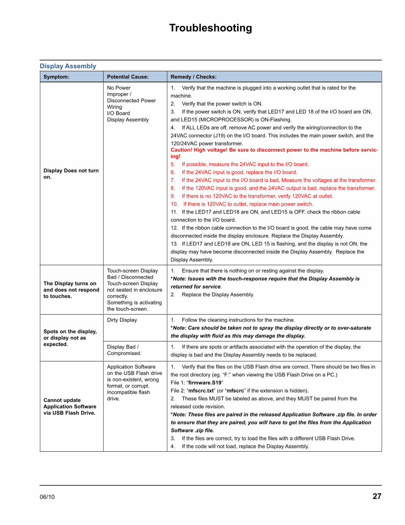
Display Assembly
Symptom: Potential Cause: Remedy / Checks:
Display Does not turn on.
No PowerImproper / Disconnected Power WiringI/O BoardDisplay Assembly
1. Verify that the machine is plugged into a working outlet that is rated for the
machine.
2. Verify that the power switch is ON.
3. If the power switch is ON, verify that LED17 and LED 18 of the I/O board are ON,
and LED15 (MICROPROCESSOR) is ON-Flashing.
4. If ALL LEDs are off, remove AC power and verify the wiring/connection to the
24VAC connector (J19) on the I/O board. This includes the main power switch, and the
120/24VAC power transformer.Caution! High voltage! Be sure to disconnect power to the machine before servic-ing!
5. If possible, measure the 24VAC input to the I/O board.
6. If the 24VAC input is good, replace the I/O board.
7. If the 24VAC input to the I/O board is bad, Measure the voltages at the transformer.
8. If the 120VAC input is good, and the 24VAC output is bad, replace the transformer.
9. If there is no 120VAC to the transformer, verify 120VAC at outlet.
10. If there is 120VAC to outlet, replace main power switch.
11. If the LED17 and LED18 are ON, and LED15 is OFF, check the ribbon cable
connection to the I/O board.
12. If the ribbon cable connection to the I/O board is good, the cable may have come
disconnected inside the display enclosure. Replace the Display Assembly.
13. If LED17 and LED18 are ON, LED 15 is flashing, and the display is not ON, the
display may have become disconnected inside the Display Assembly. Replace the
Display Assembly.
The Display turns on and does not respond to touches.
Touch-screen Display Bad / DisconnectedTouch-screen Display not seated in enclosure correctly.Something is activating the touch-screen.
1. Ensure that there is nothing on or resting against the display.
*Note: Issues with the touch-response require that the Display Assembly is
returned for service.
2. Replace the Display Assembly.
Spots on the display, or display not as expected.
Dirty Display 1. Follow the cleaning instructions for the machine.
*Note: Care should be taken not to spray the display directly or to over-saturate
the display with fluid as this may damage the display.
Display Bad / Compromised.
1. If there are spots or artifacts associated with the operation of the display, the
display is bad and the Display Assembly needs to be replaced.
Cannot update Application Software via USB Flash Drive.
Application Software on the USB Flash drive is non-existent, wrong format, or corrupt.Incompatible flash drive.
1. Verify that the files on the USB Flash drive are correct. There should be two files in
the root directory (eg. “F:” when viewing the USB Flash Drive on a PC.)
File 1: “firmware.S19”
File 2: “mfscrc.txt” (or “mfscrc” if the extension is hidden).
2. These files MUST be labeled as above, and they MUST be paired from the
released code revision.
*Note: These files are paired in the released Application Software .zip file. In order
to ensure that they are paired, you will have to get the files from the Application
Software .zip file.
3. If the files are correct, try to load the files with a different USB Flash Drive.
4. If the code will not load, replace the Display Assembly.
Troubleshooting

28 06/10
Blender and Scale
Symptom: Potential Cause: Remedy / Checks:
Blender Communication Error:
“Communication Lost
With Blender. Reset
Power to Machine”
“Lost Connection with
Blender – Restart
Machine”
No Power to Blender ControlBlender Cable / ConnectionBlender Control BoardI/O BoardDisplay Assembly
*Note: If the blender communication is good, LED14 on the I/O board will be ON.
1. Check power connections to Blender Control
2. Check serial cable connection between blender control and I/O board.
3. If the connection is good, replace the serial cable.
4. If possible, check the serial communication to a separate blender control.
5. If the error is removed with separate Blender Control, replace the Blender Control
on unit.
6. If the error remains, replace the I/O board.
7. If the error remains, replace the Display Assembly.
Blender not spinning.
Stuck / Jammed BlenderBlend Container BadBlender
1. Remove the blend container from the scale.
2. Ensure that the blades of the blend container rotate freely.
3. If the blades do not rotate, remove the obstruction or replace the blend container.
4. If the blend container is good, ensure that there is nothing obstructing the operation
of the blender mechanism.
5. From the startup screen, select [Menu] à [Managers Menu].
6. Enter code “89531”.
7. Select [Test I/O].
8. Select [Blender Ramp].
9. If the blender does not respond, replace the blender assembly.
Scale Reading Wrong
• “Blend Container
Not in Place”
• “Check Blend
Container and
Pad. Valid
Container weight
exceeded.”
Scale out of calibration / not calibrated
1. From the startup screen, select [Menu] à [Managers Menu].
2. Enter code “89531”.
3. Select [Calibrate Scale].
4. Follow the on-screen directions exactly to complete calibration.
Note: For best results, ensure that the water used for calibration is measured
accurately.
Scale not accurate / bad.
1. Ensure that there is nothing on the scale or affecting the operation of the scale.
2. From the startup screen, select [Menu] à [Managers Menu].
3. Enter code “89531”.
4. Select [Test I/O].
5. Place an empty pitcher on the scale.
6. Ensure that the pitcher is positioned on the scale correctly.
7. Record the “Scale weight”. ______
8. Measure 8 oz of water and add it to the pitcher.
9. Record the “Scale weight”. ______
10. Subtract the pitcher weight from the pitcher weight with 8oz of water. _______
11. Verify that the resulting weight is 8 oz ± 0.5 oz.
12. If the weight is not as expected, re-calibrate the scale.
13. If, after the second try, the scale is still wrong, replace the scale beam assembly.

06/10 29
Cooling
Symptom: Potential Cause: Remedy / Checks:
Cabinet Temperature Low / Product Freezing
Faulty Temperature Thermistor
1. See Product/Cabinet Thermistor debug section.
Compressor not turn-ing offI/O Board
1. From the startup screen, select [Menu] à [Managers Menu].
2. Enter code “89531”.
3. Select [Test I/O].
4. The compressor relay should be OFF.
5. If the compressor is still ON, verify that LED1 on the I/O board is OFF.
6. Verify operation of the compressor relay by cycling the relay control on and off
several times.
If the relay is good, the relay activation will have an audible “click”.
7. If the LED is cycling ON and OFF, but the relay is not ‘clicking’ replace the I/O
board.
Product Temperature High, cabinet tem-perature good.
• “High Temperature
Alarm”
Faulty Temperature Thermistor
2. See Product/Cabinet Thermistor debug section.
Duct fan obstructed /not operatingI/O Board
1. The duct fan should be ON in all modes of operation.
2. Apply power to the Smoothie Machine.
3. Open the cabinet door and observe the duct fan (upper right at the rear of the
cabinet).
4. Verify that the duct fan is not obstructed.
5. If the duct fan is OFF, check the connections from the duct fan to the I/O
Board, J8.
6. If the connections are good, replace the duct fan.
Cabinet / Product Thermistors
Symptom: Potential Cause: Remedy / Checks:
High/Low Product or Cabinet temperature reading.
• “Product Sensor
Open Failure”
• “Product Sensor
Short Failure”
• “Cabinet Sensor
Open Failure”
• “Cabinet Sensor
Short Failure”
Faulty Temperature ThermistorBad or loose wiringI/O BoardDisplay Assembly
1. From the startup screen, select [Menu] à [Inventory]
2. Record the reading for the product thermistor and the cabinet thermistor.
• An open thermistor will read -20.
• A shorted thermistor will read 140.
3. Check the connections to the I/O board.
4. If the connections are good, swap the cabinet thermistor and the product thermistor
connections on the I/O board.
5. If the problem (open/short/high reading/low reading) follows the thermistor, replace
the faulty thermistor. (Be sure to connect the correct thermistor to the correct connector.)
6. If the problem remains on either the cabinet or product reading, replace the I/O
board.
30 06/10
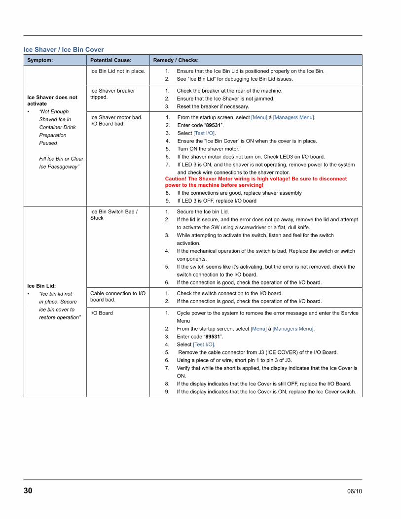
Ice Shaver / Ice Bin Cover
Symptom: Potential Cause: Remedy / Checks:
Ice Shaver does not activate
• “Not Enough
Shaved Ice in
Container Drink
Preparation
Paused
Fill Ice Bin or Clear
Ice Passageway”
Ice Bin Lid not in place. 1. Ensure that the Ice Bin Lid is positioned properly on the Ice Bin.
2. See “Ice Bin Lid” for debugging Ice Bin Lid issues.
Ice Shaver breaker tripped.
1. Check the breaker at the rear of the machine.
2. Ensure that the Ice Shaver is not jammed.
3. Reset the breaker if necessary.
Ice Shaver motor bad.I/O Board bad.
1. From the startup screen, select [Menu] à [Managers Menu].
2. Enter code “89531”.
3. Select [Test I/O].
4. Ensure the “Ice Bin Cover” is ON when the cover is in place.
5. Turn ON the shaver motor.
6. If the shaver motor does not turn on, Check LED3 on I/O board.
7. If LED 3 is ON, and the shaver is not operating, remove power to the system
and check wire connections to the shaver motor.Caution! The Shaver Motor wiring is high voltage! Be sure to disconnect power to the machine before servicing!
8. If the connections are good, replace shaver assembly
9. If LED 3 is OFF, replace I/O board
Ice Bin Lid:
• “Ice bin lid not
in place. Secure
ice bin cover to
restore operation”
Ice Bin Switch Bad / Stuck
1. Secure the Ice bin Lid.
2. If the lid is secure, and the error does not go away, remove the lid and attempt
to activate the SW using a screwdriver or a flat, dull knife.
3. While attempting to activate the switch, listen and feel for the switch
activation.
4. If the mechanical operation of the switch is bad, Replace the switch or switch
components.
5. If the switch seems like it’s activating, but the error is not removed, check the
switch connection to the I/O board.
6. If the connection is good, check the operation of the I/O board.
Cable connection to I/O board bad.
1. Check the switch connection to the I/O board.
2. If the connection is good, check the operation of the I/O board.
I/O Board 1. Cycle power to the system to remove the error message and enter the Service
Menu
2. From the startup screen, select [Menu] à [Managers Menu].
3. Enter code “89531”.
4. Select [Test I/O].
5. Remove the cable connector from J3 (ICE COVER) of the I/O Board.
6. Using a piece of or wire, short pin 1 to pin 3 of J3.
7. Verify that while the short is applied, the display indicates that the Ice Cover is
ON.
8. If the display indicates that the Ice Cover is still OFF, replace the I/O Board.
9. If the display indicates that the Ice Cover is ON, replace the Ice Cover switch.

06/10 31
Product Dispensing
Symptom: Potential Cause: Remedy / Checks:
Product Not Dispensing:
• “Drink Making
Paused”
• “Check Hose at
Pump Location”
• “Product dispense
fault – Check
Product Pomp
Lines and Nozzle”
Air line disconnectedInsufficient air pressureRegulator Bad
1. Verify that a pressurized air line is connected to the air inlet on the back of the
system.
2. Verify that the air regulator at the rear of the machine is between TBD and
TBD psi.
3. If the Air Line to the system is good, and the regulator is not reading air
pressure, replace the regulator.
Solenoid Valve Bad or wiring disconnected / bad.I/O Board
1. From the startup screen, select [Menu] à [Managers Menu].
2. Enter code “89531”.
3. Select [Test I/O].
4. While listening inside the cabinet, turn the suspect valve ON.
The valve will make an audible “click” when activated.
5. If the valve does not activate, ensure that the wiring to the valve is correct.
6. Check the relay operation on the I/O board.
If the relay is good, the relay activation will have an audible “click” and the
corresponding LED will be ON.
7. If the relay is good, and the wiring is good, replace the solenoid valve.
8. If the relay does not activate, replace the I/O board.
Product tubing obstruc-tion
1. Follow the maintenance procedures for clearing an obstruction.

32 06/10
Rinsing and Water Dispensing
Symptom: Potential Cause: Remedy / Checks:
Blend Container Rinse does not activate
Water is not connected or turned on.Ensure water is connected and turned ON (water pressure gauge)
Turn on the water source and ensure that all water connections are tight.Ensure that the water pressure is above 30 psi.
Blend container is not properly positioned over the rinse mecha-nism or improper blend container being used.
Ensure that blend container (with embedded magnet) is positioned properly over the rinse mechanism.
Reed Switch 1. From the startup screen, select [Menu] à [Managers Menu].
2. Enter code “89531”.
3. Select [Test I/O].
4. Ensure the “Rinse Reed Switch” is ON when the blend container is present.
5. If the “Rinse Reed Switch” is OFF, ensure that the blend pitcher is properly
positioned.
6. Check the connection from the Reed Switch to J4 of the I/O board.
7. If the connection is good, replace the reed switch.
Rinse Valve Bad / Stuck 1. From the startup screen, select [Menu] à [Managers Menu].
2. Enter code “89531”.
3. Select [Test I/O].
4. With the “Rinse Reed switch” ON, from the service screen, turn on the
“Rinse Solenoid”.
5. If no water, ensure that LED4 of the I/O board is ON.
6. If LED is ON, check cable connection to rinse valve.
7. If the connections are good, replace the valve.
I/O Board 1. From the startup screen, select [Menu] à [Managers Menu].
2. Enter code “89531”.
3. Select [Test I/O].
4. With the Hall Effect switch ON (blend container present), turn on the “Rinse
Solenoid”.
5. Verify that LED4 on the I/O board is ON.
6. If the LED does not activate, replace the I/O board.
Manual Water dis-pense does not activate. (Service Menu Only)
Water is not connected or turned on.Ensure water is connected and turned ON (water pressure gauge)
Turn on the water source and ensure that all water connections are tight.Ensure that the water pressure is above 30 psi.
Water Valve Bad / Stuck 1. From the startup screen, select [Menu] à [Managers Menu].
2. Enter code “89531”.
3. Select [Test I/O].
4. Turn on the “Water Solenoid”.
5. If no water, ensure that LED5 of the I/O board is ON.
6. If LED is ON, check cable connection to water valve.
7. If the connections are good, replace the valve.
I/O Board 1. From the startup screen, select [Menu] à [Managers Menu].
2. Enter code “89531”.
3. Select [Test I/O].
4. Turn on the “Water Solenoid”.
5. Verify that LED5 on the I/O board is ON.
6. If the LED does not activate, replace the I/O board.

06/10 33
Refrigeration OperationDefault temperature setpoint = 36° F with a 4° F Differential
Normal Operation
The microprocessor control board controls the cabinet temperature based on the input received from the cabinet temperature thermistor. The thermistor value is compared to the control board setpoint. When the reach-in temperature is equal or greater than the setpoint (plus half the differential) the compressor relay closes provided the following conditions are satisfied:
Power has been uninterrupted to the control board for a 3 minute period.
OR
The 3 minute compressor time delay has expired. The delay period starts after the compressor has run and then cycles off.
The blender motor is off - If the blender motor is operating the compressor relay closes when the blender motor stops (provided # 1 above is true).
The compressor relay opens when the reach-in temperature is less than the setpoint (minus half the differential).
Evaporator and Condenser Fan Motor Operation
The condenser fan motor and compressor share the same relay. The evaporator fan motor relay is energized continuously and the evaporator fan cycles off only during cleaning cycle.
Operation in the Clean/Sanitize cycle
During the weekly cleaning/sanitize cycle the evaporator fan motor relay and the condenser fan motor/compressor relay are de-energized. The relays cannot energize until the clean/sanitize cycle is complete. Upon completion of the clean/sanitize cycle the relays will energize provided the conditions listed in normal operation are satisfied.
1.
1.
2.
Maximum Compressor Run Time
After 180 minutes of cumulative compressor run time, the compressor will be de-energized for fifteen (15) minutes.
High Temp Alarm
High temp alarm will display when product thermistor is above 42ºF for 30 minutes and following conditions are satisfied
3 hours since power is applied
1 hour since cleaning cycle
Error display will reset when temperature reaches 41ºF or below.
Thermistor Failure
If the microprocessor control board receives an open or shorted cabinet thermistor signal the following will happen:
A fault is displayed on the LCD screen sensor
Cabinet sensor open
OR
Cabinet sensor shorted
The microprocessor will initiate a default sequence for the refrigeration system - 12 minutes on, 3 minutes off.
The default cycle continues until the fault is corrected or power is disconnected. Refer to Cabinet Temperature Thermistor for diagnostic procedures.
1.
•
•
1.
2.

34 06/10
Will Not Run Flowchart

06/10 35
Will Not Run Flowchart, continued

36 06/10
Weight Beam Diagnostic Flowchart

06/10 37
Ice Shaver Will Not Run Flowchart

06/10 38
ON/OFF Rocker Switch
FUNCTION
The switch is used to energize and de-energize the Blended Ice Machine.
SPECIFICATIONS
Double-pole, Double-throw switch.
CHECK PROCEDURE
Use a voltmeter/ohm meter to check rocker switch operation.
Inspect the rocker switch for correct wiring.
Isolate the rocker switch by disconnecting the wiring connectors.
Check continuity across the rocker switch terminals.
Switch Setting Meter Reading
ON Closed
OFF Open
Replace the rocker switch if continuity readings do not match both switch settings.
1.
2.
3.
1.
Transformer
FUNCTION
Reduces primary voltage to secondary voltage.
Steps down voltage from 120 or 230 VAC to 24 VDC.
SPECIFICATIONS
Steps down voltage from:
120/60/1 VAC to 24 VAC 75 VA
230/50-60/1 VAC to 24 VAC 75 VA
Normal Room Temperature or Recently De-energized Resistance:
Primary
120 VDC = 6 to 8 ohms
230 VDC = 3 to 5 ohms
Secondary
120 VDC = .3 to .5 ohms
230 VDC = .1 to 3 ohms
CHECK PROCEDURE
Use an ohmmeter to check operation. Deduct meter and lead resistance from final readings (short leads together to determine deduction value).
Inspect for correct wiring.
Isolate by disconnecting the wiring connectors.
Check primary winding resistance through terminals with an ohm meter.
Within resistance range = Transformer is good
Outside resistance range = Replace transformer
Open = Transformer fuse open, check for shorts to ground on secondary side and replace transformer.
1.
2.
3.
4.
5.
6.
Component Check Procedures

06/10 39
Control Board Fuse
FUNCTION
The control board fuse stops Blended Ice Machine operation if electrical components fail, causing high amp draw.
SPECIFICATIONS
Rating 4A 250 volt slow blow.
CHECK PROCEDURE
If the LCD display is on, the fuse is good.
! WarningDisconnect electrical power to the entire Blended Ice Machine before proceeding
Remove the fuse. Check for continuity across the fuse with an ohmmeter.
Reading Result
Open (OL) Replace Fuse
Closed (O) Fuse is Good
1.
1.
IO (Input/Output) Board
FUNCTION
Routes signals from sensors to the microprocessor control board.
Opens and closes relays based on the signals it receives from the microprocessor control board.
SPECIFICATIONS
24 VAC input
CHECK PROCEDURE
Refer to appropriate flowchart for the problem you are encountering. IO board diagnostics are covered by a process of elimination in the individual flow charts.
Reboot machine by moving toggle switch off/on
If the IO board has lights energized go to step 7.
Verify line voltage is present and the power switch is in the On position.
Verify primary voltage is present at the transformer primary.
Verify secondary voltage (24 VAC) is supplied to the IO board.
Verify the IO board fuse is good.
Verify 5 VDC at test locations on IO board.
Verify 24 VDC at test locations on IO board.
1.
2.
3.
4.
5.
6.
7.
8.
24 VAC test across the two pins
test points and ground

40 06/10
LCD Touchscreen & Microprocessor Control Board
FUNCTION
Touch screen is the user interface with the machine and sends input to the control board.
Microprocessor Control Board (MCB) monitors inputs and sends signals to the IO board to energize and de-energize components.
SPECIFICATIONS
The LCD touchscreen display and microprocessor control board are contained in one module.
CHECK PROCEDURE
Reboot machine by moving toggle switch off/on
Refer to appropriate flowchart for the problem you are encountering. Touch screen and microprocessor control board diagnostics are covered by a process of elimination. Use the individual flow charts unless the LCD screen is entirely black (no power) or entirely white (powered).
Touch screen is black
Verify processor board has energized lights - Refer to Will not Run flowchart for no lights.
Verify touchscreen power connector is connected to control board.
Touch screen is white
Verify strip connector is secure and connected by removing and reinserting connector.
Lift lock
Remove and evenly reinsert strip into connector.
Depress lock to secure strip.
Inspect strip to verify even placement.
Replace touchscreen and control board assembly.
1.
•
•
•
•
•
•
•
•
Cabinet Temperature Thermistor
FUNCTION
Supplies input to control board to indicate cabinet temperature. The control board energizes and de-energizes the compressor based on input from this thermistor.
SPECIFICATIONS
10,000 Ohms ± 2% at 25°C (77°F)
CHECK PROCEDURE
NOTE: Use a multimeter to check operation.
Reboot machine by moving toggle switch off/on.
Inspect for correct wiring.
Isolate by disconnecting the wiring connectors.
Check continuity across the terminals with an ohm meter.
Resistance = Thermistor is good
Open (OL) = Replace thermistor
NOTE: This thermistor is identical to the the duct temperature thermistor. Swapping the two thermistor connections at the IO board can be used for diagnostics.
1.
2.
3.
4.
•
•

06/10 41
Product Chase Temperature Thermistor
FUNCTION
Supplies input to control board to indicate chase temperature. The control board energizes error warning based on input from this thermistor.
SPECIFICATIONS
10,000 Ohms ± 2% at 25°C (77°F)
CHECK PROCEDURE
NOTE: Use a multimeter to check operation.
Reboot machine by moving toggle switch off/on
Inspect for correct wiring.
Isolate by disconnecting the wiring connectors.
Check continuity across the terminals with an ohm meter.
Resistance = Thermistor is good
Open (OL) = Replace thermistor
NOTE: This thermistor is identical to the the cabinet temperature thermistor. Swapping the two thermistor connections at the IO board can be used for diagnostics.
TEMPERATURE/RESISTANCE CHART
This chart is used for the product chase and temperature control thermistors. As the temperature rises at the thermistor block, the resistance drops.
If the ohmmeter reads “OL,” check the scale setting on the meter before assuming the thermistor is bad.
Temperature of Thermistor Nominal Resistance
°C °F K Ohms (x 1000)
0° - 3° 32° - 37° 32.65 - 28.05
3° - 6° 37° - 43° 28.05 - 24.17
6° - 9° 43° - 48° 24.17 - 20.88
9° - 12° 48° - 54° 20.88 - 18.09
12° - 15° 54° - 59° 18.09 - 15.71
15° - 18° 59° - 64° 15.71 - 13.68
18° - 21° 64° - 70° 13.68 - 11.94
21° - 24° 70° - 75° 11.94 - 10.45
24° - 27° 75° - 80° 10.45 - 9.17
27° - 30° 80° - 86° 9.17 - 8.06
1.
2.
3.
4.
•
•
Chase Fan
FUNCTION
Moves cool air from the cabinet through the tubing chase to maintain cabinet temperature in the beverage lines.
SPECIFICATIONS
24 VDC 5 watt
CHECK PROCEDURE
Isolate by disconnecting the wiring connectors on the IO board.
Check continuity across the terminals with an ohm meter.
Resistance = Motor is good
Open (OL) = Replace motor
1.
2.
•
•

42 06/10
Evaporator Fan
FUNCTION
Circulates air across the evaporator and throughout the cabinet interior.
SPECIFICATIONS
120/60/1 .38 amp
CHECK PROCEDURE
Use an extendable mirror and flashlight to verify fan blade rotation.
Isolate suspect motor by disconnecting the wiring connectors.
Check continuity across the terminals with an ohm meter.
Resistance = Motor is good
Open (OL) = Replace motor
Condenser Fan
FUNCTION
Moves air across the condenser fins to provide heat transfer from the condenser coil to the air stream. This warm air is used to evaporate any evaporator condensate from the drain pan.
SPECIFICATIONS
CHECK PROCEDURE
Isolate by disconnecting the wiring connectors.
Check continuity across the terminals with an ohm meter.
Resistance = Motor is good
Open (OL) = Replace motor
1.
2.
3.
•
•
1.
2.
•
•
Ice Bin Lid Microswitch
FUNCTION
Prevents operation of machine with ice bin lid removed. Two micro switches are used, one micro switch signals the control board to initiate a failure screen and the second micro switch prevents the shaver motor from running.
SPECIFICATIONS
Shaver Motor Switch - Inner switch
Control Board Input Switch - Outer switch
Normally Open, Single Throw
CHECK PROCEDURE
NOTE: Use a volt/ohm meter to check switch operation.
Inspect switch for correct wiring.
Isolate the switch by disconnecting the wiring connectors.
Check continuity across the switch terminals and refer to correct chart for switch.
Shaver Motor Switch Position
Meter Reading
Depressed C - N/O =Closed
Released C - N/O = Open
Control Board Input Switch
Position
Meter Reading
Depressed C - N/C = Closed
C - N/O = Open
Released C - N/C = Open C - N/C = Closed
Replace the switch if continuity readings do not match both switch settings.
1.
2.
3.
1.

06/10 43
Product Pump
FUNCTION
Transfers product from bag to pitcher.
SPECIFICATIONS
Pressure operated, requires a minimum pressure of 40 PSIG. Maximum pressure is 90 PSIG.
CHECK PROCEDURE
Verify cabinet temperature is not below freezing. A frozen pump can be thawed and made operational.
Perform “clearing a blocked pump procedure”.
Verify pressure regulator setting is correct.
Verify pressure is present at product pump inlet.
Disconnect pressure inlet line and product inlet and outlet lines from product pump.
Point pump inlet/outlet away from face and reconnect inlet pressure line:
Pump does not cycle - Replace pump.
Solenoid Valves
FUNCTION
Instantaneously stops flow of product through product tubing.
1.
2.
3.
4.
5.
6.
•
Shaver Motor
FUNCTION
Turns shaver wheel to supply shaved ice.
SPECIFICATIONS
Shaver motor has a circuit breaker and diode bridge block. Both components are located in the IO board compartment near the shaver motor.
Volts Direct Current (VDC)
Normal Room Temperature Resistance:
120 VDC = 30 ohms or less
230 VDC = 15 ohms or less
CHECK PROCEDURE
NOTE: Use an multimeter to check operation. Deduct meter and lead resistance from final readings (short leads together to determine deduction value).
Reboot machine by moving toggle switch off/on.
Test run manual from touchscreen.
Test rectifier - correct readings are:
Line voltage alternating current (VAC) inlet power
Line voltage direct current (VDC) outlet power
Inspect for correct wiring from rectifier to shaver motor.
Isolate shaver motor by disconnecting wiring connectors.
Check motor winding resistance through terminals with an ohm meter.
Within resistance range = Motor is good
Outside resistance range = Replace motor
Open = Replace motor
1.
2.
3.
•
•
1.
2.
3.
•
•
•
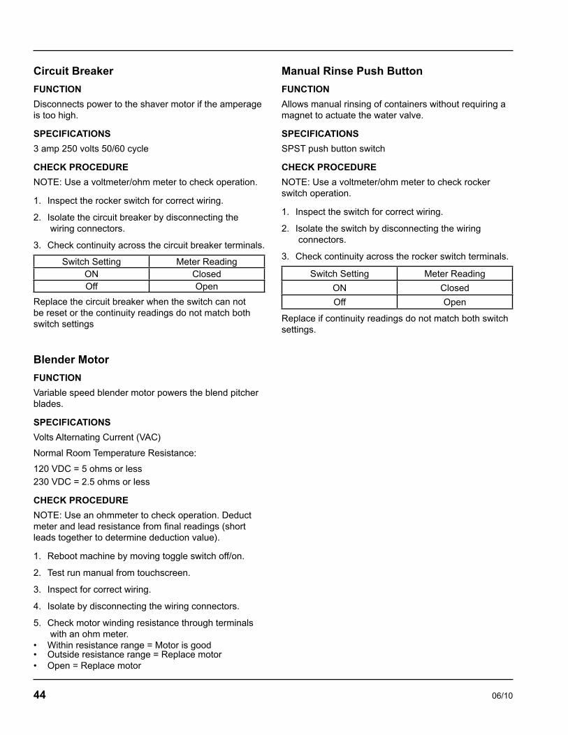
44 06/10
Circuit Breaker
FUNCTION
Disconnects power to the shaver motor if the amperage is too high.
SPECIFICATIONS
3 amp 250 volts 50/60 cycle
CHECK PROCEDURE
NOTE: Use a voltmeter/ohm meter to check operation.
Inspect the rocker switch for correct wiring.
Isolate the circuit breaker by disconnecting the wiring connectors.
Check continuity across the circuit breaker terminals.
Switch Setting Meter ReadingON ClosedOff Open
Replace the circuit breaker when the switch can not be reset or the continuity readings do not match both switch settings
Blender Motor
FUNCTION
Variable speed blender motor powers the blend pitcher blades.
SPECIFICATIONS
Volts Alternating Current (VAC)
Normal Room Temperature Resistance:
120 VDC = 5 ohms or less230 VDC = 2.5 ohms or less
CHECK PROCEDURE
NOTE: Use an ohmmeter to check operation. Deduct meter and lead resistance from final readings (short leads together to determine deduction value).
Reboot machine by moving toggle switch off/on.
Test run manual from touchscreen.
Inspect for correct wiring.
Isolate by disconnecting the wiring connectors.
Check motor winding resistance through terminals with an ohm meter.
Within resistance range = Motor is goodOutside resistance range = Replace motorOpen = Replace motor
1.
2.
3.
1.
2.
3.
4.
5.
•••
Manual Rinse Push Button
FUNCTION
Allows manual rinsing of containers without requiring a magnet to actuate the water valve.
SPECIFICATIONS
SPST push button switch
CHECK PROCEDURE
NOTE: Use a voltmeter/ohm meter to check rocker switch operation.
Inspect the switch for correct wiring.
Isolate the switch by disconnecting the wiring connectors.
Check continuity across the rocker switch terminals.
Switch Setting Meter Reading
ON Closed
Off Open
Replace if continuity readings do not match both switch settings.
1.
2.
3.

06/10 45
Compressor Electrical Diagnostics
THE COMPRESSOR DOES NOT START OR WILL TRIP REPEATEDLY ON OVERLOAD.
Check Resistance (Ohm) Values
Compressor windings can have very low ohm values. Use a properly calibrated meter.
Perform the resistance test after the compressor cools. The compressor dome should be cool enough to touch (below 120°F/49°C) to assure that the overload is closed and the resistance readings will be accurate.
Single Phase Compressors
Disconnect power then remove the wires from the compressor terminals.
The resistance values between C and S and between C and R, when added together, should equal the resistance value between S and R.
If the overload is open, there will be a resistance reading between S and R, and open readings between C and S and between C and R. Allow the compressor to cool, then check the readings again.
Check Motor Windings to Ground
Check continuity between all three terminals and the compressor shell or copper refrigeration line. Scrape metal surface to get good contact. If continuity is present, the compressor windings are grounded and the compressor should be replaced.
COMPRESSOR DRAWING LOCKED ROTOR
To determine if the compressor is seized, check the amp draw while the compressor is trying to start.
The two likely causes of this are a defective starting component and a mechanically seized compressor.
To determine which you have:
Install high and low side gauges.
Try to start the compressor.
Watch the pressures closely.
If the pressures do not move, the compressor is seized. Replace the compressor.
If the pressures move, the compressor is turning slowly and is not seized. Check the capacitors and relay.
Compressor Drawing High Amps
The continuous amperage draw on start-up should not be near the maximum fuse size indicated on the serial tag.
DIAGNOSING CAPACITORS
If the compressor attempts to start, or hums and trips the overload protector, check the starting components before replacing the compressor.
Visual evidence of capacitor failure can include a bulged terminal end or a ruptured membrane. Do not assume a capacitor is good if no visual evidence is present.
A good test is to install a known good substitute capacitor.
Use a capacitor tester when checking a suspect capacitor. Clip the bleed resistor off the capacitor terminals before testing.
DIAGNOSING START COMPONENTS
If the compressor attempts to start, or hums and trips the overload protector, check the start components before replacing the compressor.
Capacitor
Visual evidence of capacitor failure can include a bulged terminal end or a ruptured membrane. Do not assume a capacitor is good if no visual evidence is present. A good test is to install a known good substitute capacitor. Use a capacitor tester when checking a suspect capacitor. Clip the bleed resistor off the capacitor terminals before testing.
Relay
The relay has a set of contacts that connect and disconnect the start capacitor from the compressor start winding. The contacts on the relay are normally open. The relay senses the voltage generated by the start winding and closes and then opens the contacts as the compressor motor starts. The contact remain open until the compressor is de-energized.

46 06/10
Discharge Pressure High ChecklistImproper Installation
Refer to “Installation/Visual Inspection Checklist”
Air Condenser
Dirty condenser fins
High inlet air temperature (Self contained 110°F/43°C max.
Condenser discharge air recirculation
Defective fan motor
Other
Overcharged
Non-condensable (air) in system
Wrong type of refrigerant
Non-Multiplex components in system
High side refrigerant lines/component restricted
Discharge Pressure Low ChecklistImproper Installation
Refer to “Installation/Visual Inspection Checklist”
Other
Undercharged
Wrong type of refrigerant
Non-Multiplex components in system
•
•
•
•
•
•
•
•
•
•
•
•
•
•
Suction Pressure High ChecklistImproper Installation
Refer to “Installation/Visual Inspection Checklist”
Discharge Pressure
Discharge pressure is too high and is affecting low side
Improper Refrigerant Charge
Overcharged (also see Discharge Pressure High Checklist)
Wrong type of refrigerant
Components
TXV flooding
Defective compressor
Other
Non-Multiplex components in system
Suction Pressure Low ChecklistImproper Installation
Refer to “Installation/Visual Inspection Checklist”
Discharge Pressure
Discharge pressure is too low and is affecting low side – refer to “Freeze Cycle Discharge Pressure Low Checklist”
Improper Refrigerant Charge
Undercharged
Wrong type of refrigerant
Other
Non-Multiplex components in system
Restricted/plugged liquid line drier
Restricted/plugged tubing in suction side of refrigeration system
•
•
•
•
•
•
•
•
•
•
•
•
•

06/10 47
Do not purge refrigerant to the atmosphere. Capture refrigerant using recovery equipment. Follow the manufacturer’s recommendations.
ImportantMultiplex assumes no responsibility for the use of contaminated refrigerant. Damage resulting from the use of contaminated refrigerant is the sole responsibility of the servicing company.
ImportantReplace the liquid line drier before evacuating and recharging. Use only a Multiplex (O.E.M.) liquid line filter drier to prevent voiding the warranty
Connections
Blended Ice Machines are critically charged. There are no refrigerant access ports.
Locate the high and low side process tubes.
Install a piercing valve (saddle valve) on both the high and low side process tubes.
Remove piercing valves after charging. Unit is critically charged.
Purge system with nitrogen while brazing to prevent build up of copper oxide in the refrigeration system.
Manifold gauges must be removed properly to ensure that no refrigerant contamination or loss occurs. A quick disconnect is required for the high side connection unless high side valve has shut off.
•
•
•
•
•
•
Recovery/EvacuationPlace the rocker switch in the OFF position.
Install manifold gauges, charging scale, and recovery unit or two-stage vacuum pump.
Open the high and low side valves on manifold gauges.
Perform recovery or evacuation:
Recovery: Operate the recovery unit as directed by the manufacturer’s instructions.
Evacuation prior to recharging: Pull the system down to 500 microns. Then, allow the pump to run for an additional half hour. Turn off the pump and perform a standing vacuum leak check.
Check for leaks using an electronic leak detector after charging the Blended Ice Machine.
1.
2.
3.
4.
5.
6.
7.

06/10 48
- - P 2162730 FAN, TUBE AXIAL
Assembly & Replacement Parts List
Base Assembly
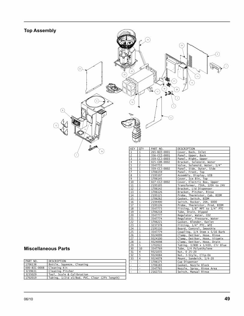
06/10 49
Top Assembly
Miscellaneous Parts
KEY QTY PART NO. DESCRIPTION1 1 265-BZZ-0001 Cover, Back, Inlet2 1 356-CCZ-0001 Panel, Upper, Back3 1 359-CCJ-0003 Panel, Right, Upper4 1 025-CDR-0002 Bracket, Solenoid, Water5 2 3547753 Valve, Solenoid, Water, 1/4”6 1 359-CCJ-0002 Panel, Side, Outer, Side7 1 1706159 Panel, Front, Top8 1 2195107 Assembly, Display, UIB9 1 1706145 Cover, Ice Bin, Top10 1 027-CCZ-0002 Cover, Electric Box, Upper11 1 2195105 Transformer, 75VA, 120V to 24V12 2 1706142 Bracket, Lid Dispenser13 1 1706126 Bracket, Pitcher, Rinse14 1 2195125 Probe, Thermistor, Cab, BIDM15 1 1706262 Gasket, Switch, BIDM16 1 2194400 Switch, Rocker, 20A, 600017 1 2195126 Probe, Thermistor, Prod, BIDM18 1 3547773 Fitting, 1/8” MPT to 1/4” PTC19 1 1706218 Tube, Drain, Dipped20 1 3547777 Regulator, Water, CO221 1 3547774 Regulator, Pressure, Water22 1 1706221 Gasket, Blender, Outlet23 1 3237378 Fitting, 1/4” PTC, WYE24 1 2195110 Board, Control, Smoothie25 1 3547779 Coupling, 1/4 Stem x 5/16 Barb26 1 9324099 Clamp, Oetiker, Hose, Rinse27 1 9324100 Clamp, Oetiker, Hose, Vitamix28 1 9324098 Clamp, Oetiker, Hose, Drain29 5 1702022 Tubing, 3/8OD x 1/4ID, Clr Blue30 10 3547769 Tube, 1/4 Polyethylene31 4 9321035 Nut, 0 25-2032 5 9324084 Nut, J-Style, Clip-On33 4 9324078 Mount, Sandwich, 1/4-20- - 1706175 Cup Dispenser- - 1706183 Gasket, Nozzle Block- - 3547765 Nozzle, Spray, Rinse Area- - 2162731 Switch, Manual Rinse
PART NO. DESCRIPTION1706138 Bottle, Squeeze, Cleaning000-BIC-0008 Cleaning Kit3239631 Cleaning Pitcher3235029 Tool, Scale & Calibration1702019 Tubing, 1/2id x5/8od, PVC, Clear (2ft length)

50 06/10
Duct Outlet Assembly
Door Assembly
KEY QTY PART NO. DESCRIPTION1 1 1706148 Cover, Dispense Manifold2 2 1706202 Rail, Retainer, Splash3 1 1706166 Block, Tube4 1 1706196 Bracket, Splash, Pitcher Outer5 1 1706201 Bracket, Splash, Inner, Lower6 1 1706200 Bracket, Splash, Inner, Upper7 1 270-CCQ-0006 Bracket, Dispenser Head8 9 1706172 Valve, Dispense Oulet, LMS9 1 372-CCQ-0009 Plate, Ambient H20- - 000-BIC-0010-S Splash Shield Assembly
KEY QTY PART NO. DESCRIPTION1 1 1706208 Gasket, Dr, Smoothie2 1 1706209 Gasket Door Access3 1 000-187-0016 Door, Whip Cream4 1 3237516 Hinge, Concealed Cart., 65INLBS5 1 3234226 Bracket, Hinge Bot RH, Top LH6 1 3234228 Bracket, Pivot, Bottom LH- - RF000066 Hinge Kit

06/10 51
Top Valve & Pump Assembly Lower Pump Assembly
KEY QTY PART NO. DESCRIPTION1 1 270-CD5-0001 COVER, EVAP, SMOOTHIE2 2 3239655 SYRUP PUMP3 1 3239636 SOLENOID BLOCK, BIM, NORGREN4 2 3239655 PUMP, PULP, FLOJET
KEY QTY PART NO. DESCRIPTION2 4 3239655 SYRUP PUMP4 1 3239636 SOLENOID BLOCK, BIM, NORGREN
VitaMix AssemblyKEY QTY PART NO. DESCRIPTION4 1 VMP00110 Container Base Plate5 1 VMP00130 PBS Container Pad7 1 VMP00125 Shaver Blade Kit (with shims)9 1 VMP00107 Paddle Nut10 1 VMP00106 PBS Ice Shelf11 1 VMP00133 Ice Bin Lid12 1 VMP00134 Safety Interlock Push Rod13 1 VMP00121 Power Cord15 1 VMP00122 Control Board16 1 VMP00124 Drive Belt, Blender
VMP00112 120V 3A Circuit BreakerVMP00114 Beam3239630 Blending Container (W/ blades)VMP00139 Blending Container OnlyVMP00138 Cable, Beam to VMVMP00135 Chain Acct Repair KitVMP00131 Container Wrench (included in VMP00135)VMP00123 Drive Belt, ShaverVMP00129 Drive SocketVMP00109 Ice Bin Grommet 3 PackVMP00136 PBS Centering ToolVMP00113 Safety Switch/Rectifier Assembly

52 06/10
Condensing Unit Assembly
Evaporator Coil Assembly
O074057

06/10 53
Charging ProceduresThe charge is critical on all Multiplex Blended Ice Machine. Use a scale to ensure the proper charge is installed. A quick disconnect is required for the high side connection.
Be sure the rocker switch is in the OFF position.
Close the vacuum pump valve and the low side manifold gauge valve.
Open the high side manifold gauge valve.
Open the refrigerant cylinder and add the proper refrigerant charge (shown on nameplate) through the discharge service valve.
Close the high side on the manifold gauge set. Add any remaining vapor charge through the suction access fitting (if necessary).
Let the system “settle” for 2 to 3 minutes.
Place the rocker switch in the ICE position.
NOTE: Manifold gauges must be removed properly to ensure that no refrigerant contamination or loss occurs.
Make sure that all of the vapor in the charging hoses is drawn into the Blended Ice Machine before disconnecting the charging hoses.
Run the Blended Ice Machine in the freeze cycle.
Verify the refrigerant cylinder valve is closed.
Open the high and low side valves on the manifold gauge set. Any refrigerant in the lines will be pulled into the low side of the system.
Allow the pressures to equalize while the Blended Ice Machine is in the freeze cycle.
Close the high and low side manifold gauge set.
Remove the hoses from the Blended Ice Machine and install the caps.
1.
2.
3.
4.
5.
6.
7.
1.
•
•
•
•
•
•
Refrigerant Recovery/Evacuation & Charging Procedures
System Contamination CleanupGeneral
This section describes the basic requirements for restoring contaminated systems to reliable service.
ImportantMultiplex assumes no responsibility for the use of contaminated refrigerant. Damage resulting from the use of contaminated refrigerant is the sole responsibility of the servicing company.
DETERMINING SEVERITY OF CONTAMINATION
System contamination is generally caused by either moisture or residue from compressor burnout entering the refrigeration system.
Inspection of the refrigerant usually provides the first indication of system contamination. Obvious moisture or an acrid odor in the refrigerant indicates contamination.
If either condition is found, or if contamination is suspected, use a Total Test Kit from Totaline or a similar diagnostic tool. These devices sample refrigerant, eliminating the need to take an oil sample. Follow the manufacturer’s directions.
If a refrigerant test kit indicates harmful levels of contamination, or if a test kit is not available, inspect the compressor oil.
Remove the refrigerant charge from the Blended Ice Machine.
Remove the compressor from the system.
Check the odor and appearance of the oil.
Inspect open suction and discharge lines at the compressor for burnout deposits.
If no signs of contamination are present, perform an acid oil test to determine the type of cleanup required.
1.
2.
3.
4.
5.

54 06/10
CONTAMINATION/CLEANUP CHART
Symptoms/Findings Required Cleanup Procedure
No symptoms or suspicion of contamination
Normal evacuation/recharging procedure
Moisture/Air Contamination symptoms Refrigeration test kit and/or acid oil test shows contamination Refrigeration system open to atmosphere for longer than 15 minutes No burnout deposits in open compressor lines
Mild contamination cleanup procedure
Mild Compressor Burnout symptoms Oil appears clean but smells acrid Refrigeration test kit or acid oil test shows harmful acid content No burnout deposits in open compressor lines
Mild contamination cleanup procedure
Severe Compressor Burnout symptoms Oil is discolored, acidic, and smells acrid Burnout deposits found in the compressor, lines, and other components
Severe contamination cleanup procedure
Mild System Contamination Cleanup Procedure
Replace any failed components.
If the compressor is good, change the oil.
Replace the liquid line drier.
NOTE: If the contamination is from moisture, use heat lamps during evacuation. Position them at the compressor, condenser and evaporator prior to evacuation. Do not position heat lamps too close to plastic components, or they may melt or warp.
Dry nitrogen is recommended for this procedure. This will prevent CFC release.
Follow the normal evacuation procedure, except replace the evacuation step with the following:
Pull vacuum to 1000 microns. Break the vacuum with dry nitrogen and sweep the system. Pressurize to a minimum of 5 psig.
Pull vacuum to 500 microns. Break the vacuum with dry nitrogen and sweep the system. Pressurize to a minimum of 5 psig.
Change the vacuum pump oil.
Pull vacuum to 500 microns. Run the vacuum pump for 1/2 hour .
NOTE: You may perform a pressure test as a preliminary leak check. You should use an electronic leak detector after system charging to be sure there are no leaks.
Charge the system with the proper refrigerant to the nameplate charge.
Operate the Blended Ice Machine.
1.
2.
3.
1.
•
•
•
•
1.
2.

06/10 55
Severe System Contamination Cleanup Procedure
Remove the refrigerant charge.
Remove the compressor.
Disassemble the hot gas solenoid valve. If burnout deposits are found inside the valve, install a rebuild kit, and replace the TXV and head pressure control valve.
Wipe away any burnout deposits from suction and discharge lines at compressor.
Sweep through the open system with dry nitrogen.
NOTE: Refrigerant sweeps are not recommended, as they release CFCs into the atmosphere.
Install a new compressor and new start components.
Install suction line filter-drier in front of compressor.
Install a new liquid line drier.
Follow the normal evacuation procedure, except replace the evacuation step with the following:
Pull vacuum to 1000 microns. Break the vacuum with dry nitrogen and sweep the system. Pressurize to a minimum of 5 psig.
Change the vacuum pump oil.
Pull vacuum to 500 microns. Break the vacuum with dry nitrogen and sweep the system. Pressurize to a minimum of 5 psig.
Change the vacuum pump oil.
Pull vacuum to 500 microns. Run the vacuum pump for 1 additional hour.
Charge the system with the proper refrigerant to the nameplate charge.
Operate the refrigeration system for one hour. Then, check the pressure drop across the suction line filter-drier.
If the pressure drop is less than 2 psig, the filter-drier should be adequate for complete cleanup.
If the pressure drop exceeds 2 psig, change the suction line filter-drier and the liquid line drier. Repeat until the pressure drop is acceptable.
Operate the refrigeration system for 48 – 72 hours. Replace the suction line and liquid line drier if necessary.
1.
2.
3.
4.
5.
6.
7.
8.
9.
•
•
•
•
•
10.
11.
•
•
•
Filter-DriersThe filter-driers used on Multiplex Blended Ice Machines are manufactured to Multiplex specifications.
A Multiplex filter-drier has high moisture and acid removal capability.
The size of the filter-drier is important. The refrigerant charge is critical. Using an improperly sized filter-drier will cause the Blended Ice Machine to be improperly charged with refrigerant.
Listed below is the recommended OEM field replacement drier:
Model Drier Size End Connection Size
MS-8-1H DML-032S 1/4”
MS-8-EH DML-032S 1/4”
Driers are covered as a warranty part. The drier must be replaced any time the system is opened for repairs.
Total System Refrigerant ChargeThis information is for reference only. Refer to the Blended Ice Machine model/serial number tag to verify the system charge. Serial plate information overrides information listed on this page.
NOTE: All machines listed use R404A refrigerant.
Model Air-Cooled
MS-8-1H 12 Ounces
MS-8-EH 12 Ounces
Operating Pressures ChartCharacteristics will vary depending on operating conditions.
OPERATING PRESSURES
Air Temperature Entering Condenser °F/°C
Discharge Pressure PSIG
Suction Pressure PSIG
50/10
70/21
80/27 205-290 48-62
90/32
100/38
110/43

06/10 56
MS-8-1H Wiring Diagram
Specifications/Wiring Diagrams/Schematics
Sol
enoi
d

06/10 57
MS-8-EH Wiring Diagram
16/3 H05V
V-F H
ARM
ON
IZED
CO
RD
PLUG
: SUITA
BLE FO
R THE
CO
UN
TRY O
F DESTIN
ATION
SHA
VER/B
LEND
ER
VITA
-MIX
CO
ND
ENSIN
G
UN
IT
EVAP FA
NEVA
P FAN
230-240 V, 50 HZ
BIM
VITA
-MIX
SERIAL
24VAC
120VAC
RINSE VA
LVE
WATER VA
LVE
J19
3 4
J11
11
J10J14
1
J12
1
J13
11
J161
J171
J15
2 12 1
J7J9
3 1 J8
TOU
CH
SCREEN
DISPLAY
SOLEN
OID
MA
NIFO
LD(1)
SOLEN
OID
MA
NIFO
LD(2)
V6
V7
V8
V5
V2
V1
V3
V4
3 1
J3
3 1
J4
MA
KE C
ON
NEC
TION
S ON
CO
MM
ON
(BO
TTOM
)
AN
D N
ORM
ALLY
OPEN
CO
NTA
CT (M
IDD
LE)
MA
KE C
ON
NEC
TION
S ON
CO
MM
ON
(BO
TTOM
)
AN
D N
ORM
ALLY
OPEN
CO
NTA
CT (M
IDD
LE)
BL(16) - 12"
BL(16) - 12"
BL(16) - 18"
WH
(16) - 20"
WH
(16) - 24"
WH
(16) - 24"
GN
(14) - 50"
GN(14)
WH(14)
BU
(16)
WH(16)
GN(16)
BL(16)
WH(16)
GN
BL
WH
GN
(16) - 24"
BU
(16) - 36"
PRO
VID
ED W
/ VITA
-MIX
SAFETY
SWITC
HIC
E BIN
OR
BLK
RD - FROM 3A BREAKER SWITCH
BL(16)
WH(16) - 12"
WH
(18) - 6"
BL(18) - 6"
BL(16) - 12"
WH(16)
BL(16)
BL(14)
GN
(14)
GN(16)
WH(14)
MA
INS SW
ITCH
TERMIN
AL
BL(14)
DU
CT FA
N
WH BL
BL(16) - 36"
RDBLU
EB
L
RD
BRN
BRN
REED SW
ITCH
WH
BL
BL
WH
OR OR
OR OR
BLK BLK
BLK BLK
BL
RD
MO
MEN
TARY
SWITC
H
BLK
OR
BRN
BRN
BRN
BRN
TRA
NSFO
RMER
"SPARE" REED
SWITC
HLA
BEL A
ND
ZIP-TIE LEA
DS
TO C
UP D
ISPENSER SU
PPOR
T RO
D
FILTER
GN(14)
BLO
CK
TOUCH SCREEN DISPLAY
LON
WO
RKS
VITA
-MIX
SERIAL
SHA
VER M
OTO
R
EVAP FA
NS
J2 PRO
BE
DU
CT
J1
CA
BIN
ET
PRO
BE
ICE C
OV
ER SWITC
HJ3
RINSE SW
ITCH
J4
PRO
DU
CT SO
LENO
IDS J15
24VAC
POW
ER IN
J19
CO
MPRESSO
R
J11J14
J12J13
J10J17
J16
RINSE VALVE
J7J9
J8
WATER VALVE
DU
CT FA
N
J6
BLA
NK
J5
BLA
NK

58 06/10
Blender Scale Schematic
Shaver Schematic
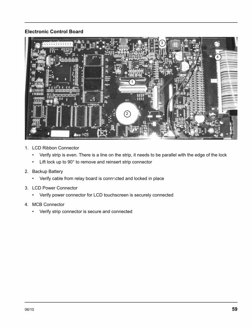
06/10 59
Electronic Control Board
LCD Ribbon Connector
Verify strip is even. There is a line on the strip, it needs to be parallel with the edge of the lock
Lift lock up to 90° to remove and reinsert strip connector
Backup Battery
Verify cable from relay board is connected and locked in place
LCD Power Connector
Verify power connector for LCD touchscreen is securely connected
MCB Connector
Verify strip connector is secure and connected
1.
•
•
2.
•
3.
•
4.
•
2
1
3
4

Thank you for choosing Manitowoc Foodservice!
Help is a phone call away. Help our team of professional, courteous customer service reps by having your model number and serial number
available at the time of your call (888) 436-5442.
Model: ____________________ S/N: ___________________
Installation Date: ____________
For a list of Manitowoc STAR authorized parts depots, visit our website at www.manitowocfsg.com.
Multiplex
Multiplex980 S. Isabella Rd., Mt. Pleasant, MI 48858, U.S.A. • (888) 436-5442 or (989) 773-7981 • Fax (888) 779-2040
DMMcDBIM8Service 06/10