Embed Size (px)
Citation preview
BIGGS & MATHEWS ENVIRONMENTAL Consulting Engineers Hydrogeologists
Mansfield Wichita Falls
1700 Robert Road, Suite 100 Mansfield, Texas 76063 Phone: 817-563-1144 Fax: 817-563-1224
January 21, 2020
Arten J. Avakian MC 124 Municipal Solid Waste Permits Section Texas Commission on Environmental Quality 12100 Park 35 Circle, Bldg. F Austin, Texas 78753
Re: Attachment 5 and Attachment 14 Permit Modification - Notice of Deficiency McCommas Bluff Landfill, TCEQ Permit No. 62 Dallas County, Texas Tracking No. 24812634; RN100752146/CN600331730
Dear Mr. Avakian:
On behalf of our client, the City of Dallas, please find attached this response to your comment letter addressed to Mr. Dennis Ware, dated December 9, 2019. The attachments with this document completely replace the attachments from the original submittal. Our responses to your comments are presented below in the order received.
1. Provide a clean replacement page for the revisions on page 5-4 of the GCRMP.
RESPONSE: A clean replacement page for Page 5-4 has been added.
2. Revise Figure 5B.1 in the GCRMP to address the following items:
a. Clarify whether wells MW-3R and MW-11R are already installed and revise thesymbol on the drawing accordingly.
b. Clarify whether well MW-22 has been installed and revise the symbol on thedrawing accordingly.
c. Confirm the location of the permit boundary on the east side of the landfill andrevise the line on the drawing accordingly.
RESPONSE: a. Monitoring wells 3-R and 11-R have been installed and the symbols on Figure 5B.1 have been revised to reflect that.
b. Monitoring well MW-22 has not yet been installed and the symbolon Figure 5B.1 has been revised to reflect that.
c. The line designations in the legend on Figure 5B.1 have beenrevised to properly reflect the permit boundary, the waste footprint,the property line and the SUP line.

Arten J. Avakian January 21, 2020 Page 2
F:\Proj\203\01\900\2019 Notice Mod\NOD Response.docx
3. Identify the “5 remediation wells,” “6 additional remediation wells,” and “11existing geoprobes” referenced in the newly added third paragraph in Section 6.0of the LGMP.
RESPONSE: Additional language has been added to the text to clarify/identify which wells and geoprobes are being referenced.
4. Indicate the boring diameter on the second passive vent detail in new Drawing 4.
RESPONSE: The drawing has been updated to show that the passive vents will have an 8-inch boring diameter.
5. Provide a schedule for landfill gas monitoring in passive vents and groundwatermonitor wells in the area where landfill gas remediation is ongoing.
RESPONSE: Due to the fact that passive vents will be open to the atmosphere and under a slight vacuum from the wind turbine, it is not expected that useful methane readings will be available from them. As such, no monitoring of the passive vents is planned.
For the monitoring wells, because methane readings above the regulatory limit have not been detected in MW-5 for over 3 years and in MW-20 for over 21 months, we are requesting that these monitoring wells be removed from the monitoring program. MW-13 will continue to be read monthly until achieving six consecutive months with methane below the regulatory limit, and then will move to quarterly monitoring. MW-4 and MW-12 will continue to be read weekly until achieving four consecutive methane readings below the regulatory limit. They will then move to monthly monitoring until they have been below the limit for six consecutive months, and then will move to quarterly monitoring. Quarterly monitoring will continue on all affected wells until approval is received from the TCEQ to cease monitoring.
It is expected that it will take up to 12 months for the installation of the passive vents to reach its full effect on LFG levels in the soil. Because of this, monitoring and evaluation is expected to continue for up to 12 months after the installation of the passive vents is completed. If elevated methane levels are still being detected 12 months after the installation of the additional passive vents, then the City will contact the TCEQ to discuss potential additional remediation measures.


ATTACHMENT 1
PERMIT MODIFICATION APPLICATION FORM

Form
Facility Name: Permittee/Registrant Name:MSW Authorization #: Initial Submittal Date: Revision Date:
Texas Commission on Environmental QualityPermit/Registration Modification and Temporary Authorization
Application Form for an MSW Facility
1. Reason for Submittal
2. Authorization Type
3. Application Type
4. Application Fees
5. Application URL
https://
dallascityhall.com/departments/sanitation
6. Confidential Documents
McCommas Bluff LandfillCity of Dallas
6211/21/2019
1/21/2020
■
582EA000366088

Form
7. General Facility Information
8. Facility Type(s)
9. Description of the Revisions to the Facility
McCommas Bluff Landfill 11/21/2019
62 1/21/2020
McCommas Bluff Landfill
62
RN100752146
5100 Youngblood Road
Dallas Dallas TX 75241
214-671-0230
32°40'59.5596" N -96°43'29.1324" W
The purpose of this permit modification is to modify two attachments in theMcCommas Bluff Landfill's Site Development Plan, Attachment 5 - GroundwaterCharacterization Report and Groundwater Monitoring Plan and Attachment 14 -Landfill Gas Management Plan.
Attachment 5 is being updated to address the relocation of three groundwatermonitoring wells due to a previous landfill modification to the waste cell boundaries.This update relocates the point of compliance out of the permitted waste footprint.Attachment 14 is being updated to incorporate Landfill Gas (LFG) extraction wells andpassive vents installed for the purpose of mitigating LFG migration into nearbygroundwater monitoring wells.
This permit modification is being submitted under §305.70(k)(3) and §305.70(k)(4).

Form
10. Facility Contact Information
Site Operator (Permittee/Registrant) Name:
Operator Name1:
Consultant Name (if applicable):
Agent in Service Name (required only for out-of-state):
McCommas Bluff Landfill 11/21/2019
62 1/21/2020
City of Dallas
600331730
3112 Canton Street
Dallas Dallas TX 75226
214-671-0230
Same as Site Operator (Permittee/Registrant)
Biggs and Mathews Environmental
F-256
1700 Robert Road, Suite 100
Mansfield Tarrant TX 76063
817-563-1144

Form
11. Ownership Status of the Facility
Owner Name:
McCommas Bluff Landfill 11/21/2019
62 1/21/2020

Form
Permit/Registration Modification with Public Notice
Required Attachments Attachment No.
Additional Attachments as Applicable- Select all those apply and add as necessary
McCommas Bluff Landfill 11/21/2019
62 1/21/2020
2
2
3
4

ATTACHMENT 2
LAND OWNERSHIP LIST/MAP

McCommas Landfill Adjacent Property Owners
Dallas Central Appraisal District, November 19, 2019
Biggs & Mathews Environmental 1 McCommas Landfill M:\Proj\203\01\103\2019\Landowners List.docx
1 QUALITY AUTO RECYCLERS LLC 1001 W PLEASANT RUN RD DESOTO TX 75115-2801
13 JOSE H VALDEZ & MARIA DELCARMEN VALDEZ 3922 SHINDOLL ST DALLAS TX 75216-4027
2 DP RESOURCES LLC 9727 STONE RIDGE CIRCLE DALLAS TX 75231
14 MARTIN RAMIRO AVILA 3104 POINT EAST DR MESQUITE TX 75150-2638
3 BROWN FAMILY LEWISVILLE RR FAMILY 1ST LP 5610 HARBOR TOWN DR DALLAS TX 75287-7413
15 440 EQUIPMENT LLC 5111 GREENVILLE AVE #601655 DALLAS TX 75360-0680
4 LLOYD E MILLER 10305 S CENTRAL EXPY DALLAS TX 75241-7316
16 COUNTY OF DALLAS 411 ELM ST DALLAS TX 75202-3301
5 JACK & LOIS APPERSON 1113 GREENBRIAR DR GARLAND TX 75043-5321
17 NICKS BIG TRUCK SALES 417 SUNFLOWER ST RED OAK TX 75154-4221
6 BRUCE & GAY FRAZER 2929 WESTMINSTER AVE DALLAS TX 75205-1508
18 COMET AUTO SALVAGE INC PO BOX 711 HUTCHINS TX 75141-0711
7 ONCOR ELECTRIC DELIVERY COMPANY PO BOX 139100 DALLAS TX 75313-9100
19 ENVIRONMENTAL INVESTMENTS LP 3048 HIGH RIDGE DR GRAPEVINE TX 76051-6807
8 METROPOLITAN SAND & GRAVEL CO LLC 10 MARYVIEW LN SAINT LOUIS MO 63124-1247
20 CASA FLORA INC PO BOX 41140 DALLAS TX 75241-0140
9 ELISEO J & AMAPOLA MARTINEZ 1201 SHADY GROVE IRVING TX 75060-6219
21 ANGELA ONEAL ET AL 9734 SOPHORA CIR DALLAS TX 75249-1422
10 PRESTIGE GRAM VENTURE LLC 7045 PORTOBELLO DR PLANO TX 75024-7570
22 SOUTHERN PACIFIC TRANS CO 1400 DOUGLAS ST STOP 1640 OMAHA NE 68179-1001
11 GERALDINE G CANGELOSE 804 KELLI CIR SULPHUR SPRINGS TX 75482-5078
23 UTSI FINANCE INC 12755 E 9 MILE RD WARREN MI 48089-2621
12 MARGARITO HERNANDEZ LOPEZ 2758 GLADSTONE DR DALLAS TX 75211-5205
24 SOUTHWEST PERENNIALS INC P O BOX 170867 DALLAS TX 75217-0867

McCommas Landfill Adjacent Property Owners
Dallas Central Appraisal District, November 19, 2019
Biggs & Mathews Environmental 2 McCommas Landfill M:\Proj\203\01\103\2019\Landowners List.docx
25 CALVIN H SHAHAN 1600 NOKOMIS RD LANCASTER TX 75146-5547
37 RANDALL RHODES 462 LOMA LINDA PALMER TX 75152-8149
26 GERALDINE GENEVA 804 KELLI CIR SULPHUR SPRINGS TX 75482-5078
38 MULAT AHMED MUHAMED 2513 REDBROOK DR GARLAND TX 75040-3740
27 SONIA MARILU GARCIA MELENDEZ 9919 BERMUDA DR DALLAS, TX 75241-7342
39 GAYTAN PROPERTIES LTD 801 PELLEGRINO CT LAREDO TX 78045-8216
28 U S REALTY HOLDINGS LTD 2415 W NORTHWEST HWY STE 105 DALLAS TX 75220-4446
40 RUIBAL FARMS LP 601 S PEARL EXPWY DALLAS TX 75201-6013
29 OMAR ACEITUNOFUENTES 9319 BERMUNDA RD DALLAS TX 75241
41 LEONARDO ANDRADE PO BOX 571 HUTCHINS TX 75141-0571
30 HUFFHINES PROPANE LLC PO BOX 709 HUTCHINS TX 75141-0709
42 CAMILO RODEA 9430 BERMUDA RD DALLAS TX 75241-7338
31 ANASTACIO SAMPAYO & SONIA SANCHEZ 3006 RUIDODO AVE DALLAS TX 75228
43 ADALBERTO YANEZ FLORES 9433 S CENTRAL EXPY DALLAS TX 75241-7325
32 MARY LOU COULSTON LF EST 9325 BERMUDA RD DALLAS TX 75241-7342
44 METROPOLITAN SERVICES LLC 2717 WICKHAM CT PLANO TX 75093
33 JACOBO HERNANDEZ & MARIA DEL ROSARIO 9331 BERMUDA RD DALLAS TX 75241-7342
45 LU ROS MACHINE INC. 9449 S CENTRAL EXPY DALLAS TX 75241-7325
34 CAR REY INC 9303 CORIANDER PL DALLAS TX 75217-8656
46 DESEV INVESTMENT GROUP LLC 310 OXFORD DR RICHARDSON TX 75080-5411
35 GENARO VINIEGRA 9339 BERMUDA RD DALLAS TX 75241-7342
47 ALMIRA INDUSTRIAL & TRADING CORP PO BOX 143343 IRVING TX 75014-3343
36 HELIODORO VINIEGRA & MARIA VINIEGRA 9340 BERMUDA RD DALLAS TX 75241-7337
48 GACHMAN METAL & RECYCLING INC. PO BOX 308 FORT WORTH TX 76101-0308

McCommas Landfill Adjacent Property Owners
Dallas Central Appraisal District, November 19, 2019
Biggs & Mathews Environmental 3 McCommas Landfill M:\Proj\203\01\103\2019\Landowners List.docx
49 US DELIVERY LLC 302 BROOKWOOD DR RICHARDSON TX 75080-4730
50 THE NELAN COMPANY PO BOX 180101 DALLAS TX 75218-0101
51 IRENE VAZQUEZ 9915 S CENTRAL EXPY DALLAS TX 75241-7320
52 UNION PACIFIC RR CO 1400 DOUGLAS ST STOP 1640 OMAHA NE 68179-1001
53 CITY OF DALLAS 1500 MARILLA ST DALLAS TX 75201
54 ASTEROID AUTO SALVAGE INC. 10701 CF HAWN FWY DALLAS TX 75217-8049
55 WHITE ANDRE 9255 S. CENTRAL EXPY DALLAS TX 75241-7512
56 CCR EQUITY HOLDINGS ONE LLC 906 W MCDERMOTT DRIVE STE 116-321 ALLEN TX 75013-6510

L <l>
<l> a..
OCl
0 N
0 "'
/
0 / "' 0
-✓-
lRINITY RIVER
I
\
\
I ,
I
0
CD
INSET A
FOR PERMITTING PURPOSES ONLY
REVISIONS
1/B 1/4
SCALE IN MILES
WzEl!ID.
PERMIT BOUNDARY
LAND OWNERSHIP IDENTIFICA 11ON
LAND OWNED BY THE CITY OF DALLAS
1/4 MILE RADIUS
PROPERlY OWNERS WITHIN 1 / 4 MILE
CITY OF DALLAS
McCOMMAS BLUFF LANDFlLL
DSN. JHP DWN. SRC
II_ II BIGGS & MATHEWS
ENVIRONMENTAL CONSULTING ENGINEERS
MANSFIELD • WICHITA FALLS 817-563-1144
DATE : 11 19
SCALE : GRAPHIC
TBPG FIRM NO. 50222
DRAWING
REV DATE DESCRIPTION DWN BY DES BY CHK BY APP BY CHK. JHP DWG : QuorterMileOwnership.DWG 1
ATTACHMENT 3
PERMIT REPLACEMENT PAGES (REDLINE/STRIKEOUT FORMAT)

SITE DEVELOPMENT PLAN
ATTACHMENT 5

TEXAS BOARD OF PROFESSIONAL ENGINEERS FIRM REGISTRATION NO. F-256
TEXAS BOARD OF PROFESSIONAL GEOSCIENTISTS FIRM REGISTRATION NO. 50222
MCCOMMAS BLUFF LANDFILL DALLAS COUNTY, TEXAS TCEQ PERMIT NO. MSW 62
PERMIT MODIFICATION
ATTACHMENT 5 GROUNDWATER CHARACTERIZATION REPORT AND
GROUNDWATER MONITORING PLAN
Prepared for
City of Dallas
February 2009 Revised June 2009 Revised June 2014
Revised January 2020
Prepared by
BIGGS & MATHEWS ENVIRONMENTAL 1700 Robert Road, Suite 100 Mansfield, Texas 76063 817-563-1144
Biggs & Mathews Environmental 5-ii McCommas Bluff Landfill M:\PROJ\203\01\103\2019\ATT 5.DOC Rev. 3, 1/15/20
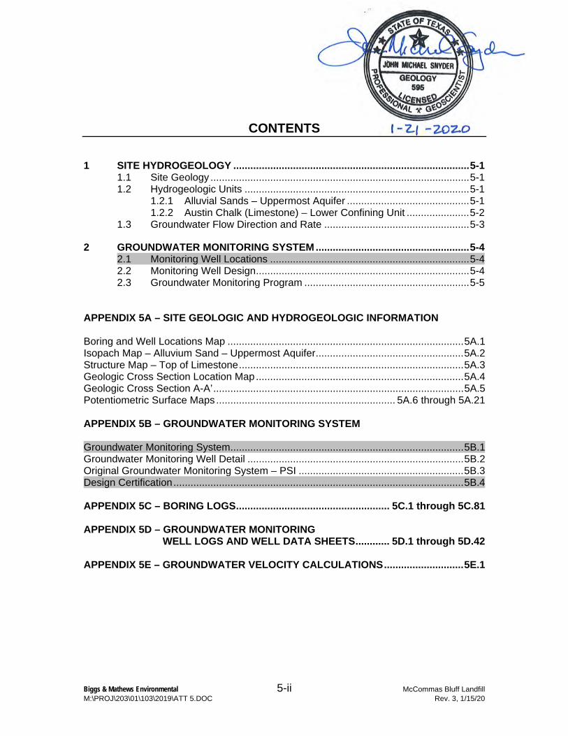
CONTENTS
1 SITE HYDROGEOLOGY ................................................................................... 5-1 1.1 Site Geology ........................................................................................... 5-1 1.2 Hydrogeologic Units ............................................................................... 5-1
1.2.1 Alluvial Sands – Uppermost Aquifer ........................................... 5-1 1.2.2 Austin Chalk (Limestone) – Lower Confining Unit ...................... 5-2
1.3 Groundwater Flow Direction and Rate ................................................... 5-3
2 GROUNDWATER MONITORING SYSTEM ...................................................... 5-4 2.1 Monitoring Well Locations ...................................................................... 5-4 2.2 Monitoring Well Design ........................................................................... 5-4 2.3 Groundwater Monitoring Program .......................................................... 5-5
APPENDIX 5A – SITE GEOLOGIC AND HYDROGEOLOGIC INFORMATION
Boring and Well Locations Map ................................................................................... 5A.1 Isopach Map – Alluvium Sand – Uppermost Aquifer .................................................... 5A.2 Structure Map – Top of Limestone ............................................................................... 5A.3 Geologic Cross Section Location Map ......................................................................... 5A.4 Geologic Cross Section A-A’ ........................................................................................ 5A.5 Potentiometric Surface Maps ............................................................... 5A.6 through 5A.21
APPENDIX 5B – GROUNDWATER MONITORING SYSTEM
Groundwater Monitoring System .................................................................................. 5B.1 Groundwater Monitoring Well Detail ............................................................................ 5B.2 Original Groundwater Monitoring System – PSI .......................................................... 5B.3 Design Certification ...................................................................................................... 5B.4
APPENDIX 5C – BORING LOGS ...................................................... 5C.1 through 5C.81
APPENDIX 5D – GROUNDWATER MONITORING WELL LOGS AND WELL DATA SHEETS ............ 5D.1 through 5D.42
APPENDIX 5E – GROUNDWATER VELOCITY CALCULATIONS ............................ 5E.1

Biggs & Mathews Environmental 5-iii McCommas Bluff Landfill M:\PROJ\203\01\103\2019\ATT 5.DOC Rev. 3, 1/15/20
LIST OF TABLES
Table Page
Table 1 – Slug Test Results ........................................................................................... 5-2 Table 2 – Historical Groundwater Elevations ................................................................. 5-6 Table 3 – Monitoring Well Details .................................................................................. 5-7

Biggs & Mathews Environmental 5-4 McCommas Bluff Landfill M:\PROJ\203\01\103\2019\ATT 5.DOC Rev. 3, 1/15/20
2 GROUNDWATER MONITORING SYSTEM
2.1 Monitoring Well Locations
A revised monitoring system is herein proposed and shown on Figure 5B.1 that meets the spacing requirements of Subchapter J. Spacing between all wells in the proposed system is less than 600 feet.
The existing groundwater monitoring system monitors the Alluvium overlying the Austin Chalk. The existing approved system consists of 16 wells (3 upgradient and 13 downgradient wells) that are currently installed. The remaining wells in the approved system are to be phased in as cell development progresses in the northeast part of the site. The location of the approved monitoring plan is shown on Figure 5B.3.
The system will ultimately consist of 29 monitoring wells. MW-1, MW-2, and MW-10 are existing upgradient wells. MW-3R, MW-4, MW-5, MW-6, MW-7R, MW-11R, MW-12, MW-13, MW-14R, MW-15, MW-16, MW-17, MW-18, MW-19, MW-20, and MW-21 are currently installed. MW-3R and MW-11R (which will replace existing MW-3 and MW-11) will be installed following approval of this modification.
The other proposed wells will be installed in a phased approach tied to future cell development. Specifically, MW-22 through MW-25 will be installed prior to waste filling in Cell 7A, MW-26 through MW-28 will be installed prior to waste filling in Cell 8, and MW-29 through MW-31 will be installed prior to waste filling in Cell 9. The monitoring well locations are shown on Figure 5B.1. The monitoring well details are included on Figure 5B.2.
There will be no lapse in detection monitoring while background is obtained for new wells. Wells in the existing monitoring system that are proposed to be plugged and abandoned will continue in detection monitoring until detection monitoring can begin in the modified monitoring system.
2.2 Monitoring Well Design
Groundwater monitoring well details are shown on Figure 5B.2 of this attachment. Typically, the wells consist of 4-inch diameter, flush-threaded PVC (Schedule 40) with 0.01-inch slotted PVC screens. Monitoring wells will have 10-foot screens. The filter pack sand will be a 20-40 grade silica sand and will be placed from total well depth to about 3 feet above the top of the well screen. A 3-foot-thick bentonite seal consisting of bentonite pellets will be hydrated in place on top of the filter pack sand. The remainder of the well boring is pressure grouted with bentonite grout to within 2 feet of the surface.

Biggs & Mathews Environmental 5-7 McCommas Bluff Landfill M:\PROJ\203\01\103\2019\ATT 5.DOC Rev. 3, 1/15/20
Table 3 McCommas Bluff Landfill Monitoring Well Details
Monitoring Well No.
Northing Easting
Ground Elevation
Total Well Depth
Top of Casing
Elevation
Depth to Groundwater
Screened Interval
(ft)
Filter Pack Interval
(ft)
(ft/msl) (ft/msl) (ft) (ft/msl) (ft) From To From To
Currently Approved Monitoring Wells
MW-1 274.43 757.33 398.90 370.40 28.50 400.73 12.40 17.50 27.50 12.00 28.50
MW-2 -1493.27 652.26 397.75 349.25 48.50 399.82 30.00 36.50 46.50 18.00 48.50
MW-3 -3330.70 1694.48 390.95 359.95 31.00 394.95 17.50 20.00 30.00 12.00 31.00
MW-4 -3320.27 2888.79 408.98 353.59 55.39 412.36 34.00 44.69 55.19 42.89 55.39
MW-3R -3466.32 1682.19 387.65 358.65 29.0 389.96 19.02 18.50 28.50 16.50 29.0
MW-5 -3318.03 4087.43 410.03 353.03 57.00 413.47 40.30 46.10 56.60 45.00 57.00
MW-6 -3316.26 5277.17 410.74 353.59 57.15 413.47 33.00 46.65 57.15 44.65 57.15
MW-7R -3287.13 6654.99 404.00 324.00 80.00 406.44 37.30 69.00 79.00 35.00 80.00
MW-10 2819.11 2121.16 408.23 367.73 40.50 410.70 19.00 29.40 39.90 27.50 40.50
MW-11 -3282.88 2230.41 412.06 357.06 55.00 415.80 44.00 37.00 55.00 35.00 55.00
MW-11R -3487.80 2148.53 385.73 359.23 26.5 388.30 17.28 16.00 26.00 14.00 26.5
MW-12 -3337.86 3493.64 409.58 347.53 62.05 413.39 34.00 39.05 62.05 37.05 62.05
MW-13 -3332.73 4686.08 406.00 348.88 57.12 409.24 42.00 32.12 57.12 27.12 57.12
MW-14R -3322.64 5731.55 407.40 357.90 49.50 409.86 37.00 39.50 49.50 34.50 49.50
MW-15 -3051.76 7204.41 403.00 321.00 82.00 405.85 37.83 72.00 82.00 40.00 82.00
MW-16 -2623.38 7618.84 403.10 346.10 57.00 406.60 34.37 47.00 57.00 29.00 57.00
MW-17 -2065.75 7838.63 403.00 343.00 60.00 406.73 35.58 50.00 60.00 30.00 60.00
MW-18 -1489.56 8007.27 403.10 341.10 62.00 406.77 36.05 52.00 62.00 32.00 62.00
MW-19 -3282.78 1152.39 402.57 351.57 51.00 405.18 27.18 41.00 51.00 36.00 51.00
MW-20 -3315.26 2588.15 410.03 360.53 49.50 412.36 36.00 39.50 49.50 34.00 49.50
MW-21 -3319.98 6196.52 407.23 355.23 52.00 409.63 37.05 42.00 52.00 36.50 52.00
MW-22* -1077.06 8436.07 403.00 337.00 63.00 402.00 19.00 53.00 63.00 47.50 63.00
MW-23* -605.89 8776.11 402.00 343.00 47.00 392.00 17.00 37.00 47.00 31.50 47.00
MW-24* -43.63 8900.70 401.00 347.00 37.65 386.65 11.00 27.65 37.65 22.15 37.65
MW-25* 475.09 8696.34 402.00 353.00 31.01 386.01 11.00 21.01 31.01 15.51 31.01
MW-26* 944.39 8343.37 400.00 350.00 50.00 402.00 27.00 40.00 50.00 34.50 50.00
MW-27* 1224.85 7837.83 400.00 345.00 55.00 402.00 27.00 45.00 55.00 39.50 55.00
MW-28* 1403.41 7270.25 400.00 345.00 55.00 402.00 27.00 45.00 55.00 39.50 55.00
MW-29* 1757.04 6821.33 400.00 355.00 45.00 402.00 27.00 35.00 45.00 29.50 45.00
MW-30* 2280.86 6539.12 400.00 365.00 35.00 402.00 27.00 25.00 35.00 19.50 35.00
MW-31* 2673.68 6141.32 400.00 370.00 30.00 402.00 27.00 20.00 30.00 14.50 30.00
Proposed Monitoring Wells
MW-3R -3466.32 1682.19 390.00 360.00 30.00 392.00 17.00 20.00 30.00 14.50 30.00
MW-11R -3487.80 2148.53 390.00 360.00 30.00 392.00 17.00 20.00 30.00 14.50 30.00
*Wells will be installed prior to waste filling in Cells 7A, 8, and 9

MCCOMMAS BLUFF LANDFILL
APPENDIX 5B
GROUNDWATER MONITORING SYSTEM

""'::::,
N ...J °" .;..; :, 0 >s
c,, "' "O
w (/)
°" I
I (I] "' /"' 0
/
"' 0
r-, l---
a I �'
.o,,
�
8 I 8 ,ro.oc,
N 4000�-----�-------N�-----�n------��-----��+------ro�----"",?l}--',-+,�-�'------00�----�a, N 4000
1. EXISTING CONTOURS COMPILED FROM AERIAL SURVEY BY L.ANDATADATED SEPTEMBER, 2D06 AND SUPPLEMENTED WITH GROUNDSURVEY ON JUNE 6, 2011 BY DALl.AS SANITATION AND JULY 27, 2012 BY L.ANDTEC ENGINEERS.
2. PERMIT LIMIT LOCATION ADAPTED FROM AS RECORD DRAWINGS BYHALFF ASSOCIATES.
3. WELLS LOCATED WITH L.ANDTEC'S SURVEY DATED NOVEMBER 25,' 2008.
'"""-.
4. MONITORING WELLS MW-14R, MW-19, MW-20, AND MW-21 WERE- - - --· - - -- - - -- - - - - - - --"'-., INSTALLED IN DECEMBER 2009.
N 3ooo>--------+-+-------+--------+------>--------+-------+--------+-----'--..-+-... _____ -_-_-_T
R
-I
N
-+-I N
R
:�:0�5. MONITORING WELL MW-14 WAS PLUGGED/ABANDONED IN MW 10
- - -- - .-:,-:::::::; -=-==1==-=-�=-=-=--:;:-·------ - --I
- ---r---
DECEMBER 2010.
--------......... '
1 I I
N 2ooof----�-1-t--+-__ -_-_--, ____ I l--++----f--------;!_f------'
1
--f-----1
1---f--l-----'--f--..-C-----f------f---l--
N 0
N- 200
N- 300
I I
II
I
�MW
MW-2
------
SECTOR 1
SECTOR 2
,------- -------1
@: @: I r----I I IIII
@) I I
IIt----
SECTOR 3
300'
I I
I
I SECTO
I
r--T
0
SECTOR 3b
--.......
I
I
I
I
I 3d I
1---
7....I
I
@: @I
@
I
I _L_-.
I
©
454'
@
I
I L-,-
I
@
I I
®
0
---
I
______ J
I
I
/ I
I
\I '
---
N- 4000-----, -----+------+---------+--------+----------+------+---------+--------+----------+---------<,N- 4000
I '\
'
' '
\
I
I
I I
\
I
I
I
0
N 1000
I I
I
I
I
/ I
'--+------ ----- ----ISSUED FOR PERMITTING PURPOSES
N- 500�-------+--------+----------+------+---------+--------+----------+------+---------+------�
REVISIONS
N- so,.__-+---+- --- - - - - - - --+-�
REV DAT£ DESCRIPTION DWN BY
..LEGEliD -- - - - -- PROPERlY LINE
----N 3000
PERMIT BOUNDARY WASTE LIMIT
CELL BOUNDARY
SUP LIMIT SITE GRID
POINT OF COMPLIANCE
SLURRY WALL
♦ MW-2 MONITORING WELL
♦ MW-z1 TO BE INSTALLED MONITORING WELL
♦ MW-24 PREVIOUSLY APPROVED MONITORING WELL LOCATION
® CELL NUMBER
0 500 1000
-
'--�
I I '1:-
r- ,fJ <i:'
I §!: #
N- 2000
N- 3000
,� w
0
SCALE IN FEET
N D
N- 1000
GROUNDWATER MONITORING SYSTEM
CnY OF DALLAS
McCOMMAS BLUFF LANDFILL
ATTACHMENT 5 PERMIT MODIFICATION
TBPG FIRM NO, 50222
BIGGS & MATHEWS ENVIRONMENTAL
CONSULTING ENGINEERS MANSFIELD • WICHITA FALLS
817-563-1144
FIGURE
58.1


SITE DEVELOPMENT PLAN
ATTACHMENT 14

ATTACHMENT 14
LANDFILL GAS MANAGEMENT PLAN
McCOMMAS BLUFF LANDFILL
PERMIT NO. MSW-62
CITY OF DALLAS
DALLAS COUNTY, TEXAS
Prepared by Robert W. Mosley, P.E.
March 1994
Revised
July 1998 June 2001
February 2002 September 2006
May 2016 January 2020
FOR PERMIT MODIFICATION REVISIONS TO SECTION 6 AND
APPENDIX 1

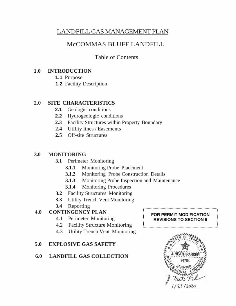
LANDFILL GAS MANAGEMENT PLAN
McCOMMAS BLUFF LANDFILL
Table of Contents
1.0 INTRODUCTION 1.1 Purpose 1.2 Facility Description
2.0 SITE CHARACTERISTICS 2.1 Geologic conditions 2.2 Hydrogeologic conditions 2.3 Facility Structures within Property Boundary 2.4 Utility lines / Easements 2.5 Off-site Structures
3.0 MONITORING 3.1 Perimeter Monitoring
3.1.1 Monitoring Probe Placement 3.1.2 Monitoring Probe Construction Details 3.1.3 Monitoring Probe Inspection and Maintenance 3.1.4 Monitoring Procedures
3.2 Facility Structures Monitoring 3.3 Utility Trench Vent Monitoring 3.4 Reporting
4.0 CONTINGENCY PLAN 4.1 Perimeter Monitoring 4.2 Facility Structure Monitoring 4.3 Utility Trench Vent Monitoring
5.0 EXPLOSIVE GAS SAFETY
6.0 LANDFILL GAS COLLECTION
FOR PERMIT MODIFICATION REVISIONS TO SECTION 6

Biggs & Mathews Environmental 14-16 McCommas Bluff Landfill M:\PROJ\203\01\103\2019\SECTION 6.DOCX January 21, 2020
6.0 LANDFILL GAS COLLECTION
Existing LFG Collection and Control System
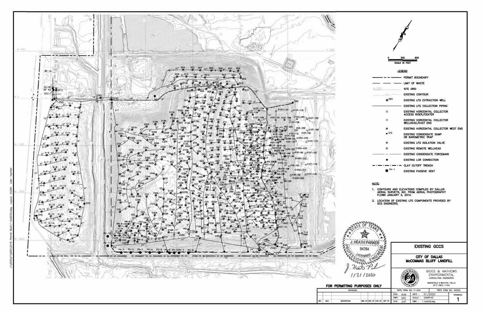
Currently, the site has an active LFG collection and control system (GCCS), as shown in Appendix D of Appendix 1 on Drawing 1. The existing GCCS consists of vertical LFG extraction wells, a piping network, a condensate management system, and a blower/flare facility, and a landfill gas-to-energy (LFGTE) facility. The existing blowers provide vacuum to the extraction wells through the LFG collection piping network. The extracted LFG is routed from the collection points to the LFGTE facility. Any remaining extracted LFG not sent to the LFGTE facility is diverted to an on-site flare where the gas is combusted.
From 2000-2015, approximately 265 wells were drilled, 119 wells were redrilled, and 35 horizontal collectors were added to the GCCS. These wells and horizontals are shown on Drawing 2 in Appendix D of Appendix 1.
In 2015, 5 remediation wells (RW-1 through RW-5) were installed in Sector 3C to limit migration of LFG in this area. In 2016, 6 additional remediation wells (RW-6 through RW-11) were installed in Sector 3C. All of these wells were completed similar to typical extraction wells at the site, except that they were drilled to within 5 feet of the bottom of waste. Following the installation of the remediation wells, 11 existing (PV-1 through PV-9, PV-11, and PV-12) geoprobes outside of waste near the edge of Sector 3C and Cell 1 were converted to passive vents. The locations of the remediation wells and passive vents is shown on Drawing 2A in Appendix D of Appendix 1.
In 2020, three of the existing converted passive vents (PV-1, PV-4, and PV-5) will be removed and replaced with passive vents with a larger diameter casing. Also, eight additional passive vents will be added in the area between PV-2 and PV-6 to provide a closer spacing between the vents in order to better intercept any potential migrating LFG. Three additional passive vents will also be added near MW-13. These additional passive vents are also shown on Drawing 2A in Appendix D of Appendix 1.
In addition, a shallow clay cutoff trench has been constructed on the south side of the site adjacent to Sector 3C, Cell 1, and Cell 2. This trench was installed near the limits of waste, above the anchor trench, to serve as a barrier to prevent potential migration of LFG using the liner protective cover layer as a pathway. To install the trench, all of the soil above the anchor trench, including the protective cover, was excavated. This area was then backfilled with compacted clay to ground surface.
As additional waste is placed, the existing LFG extraction wells will be extended and/or redrilled as necessary.

Biggs & Mathews Environmental 14-17 McCommas Bluff Landfill M:\PROJ\203\01\103\2019\SECTION 6.DOCX January 21, 2020
Future GCCS Expansions
As the site develops, additional extraction wells will be installed as needed to reduce the buildup of internal gas pressures caused by the increased generation of LFG. Additional blowers and piping network will be installed as needed to provide the vacuum and capacity to handle the flow rate of LFG in the future.
Operation and Maintenance
Wellhead and system monitoring will be performed on a routine basis to monitor overall system performance. As needed, system adjustments will be made to optimize the extraction of LFG from the landfill to control LFG migration, odors, and greenhouse gases. In addition, the system will be routinely visually inspected for any evidence of needed repairs or other maintenance. General maintenance procedures will include the following:
Each wellhead will be monitored and adjusted as needed to control LFG whilereducing oxygen intrusion into the landfill.
Condensate sumps will be checked for proper operation.
Blowers and flares will be inspected for proper operation.

LANDFILL GAS COLLECTION AND CONTROL SYSTEM DESIGN PLAN REPORT CITY OF DALLAS MUNICIPAL SOLID WASTE LANDFILL – MSW PERMIT No. 62
Appendix 1 to Attachment 14
Prepared for City of Dallas
Dallas, TX
Original Report July 1998
Revised June 2001
Supplement to June 2001 Revision-February 2002
Revised September 2006
Revised May 2016
Revised January 2020
FOR PERMIT MODIFICATION REVISIONS TO APPENDIX 1

N 1000
N 0
N- 1000
0
.c
w
N- 2000 w
0
0 0
w I
"§ N- 3000 (L
(X)
I: 0 N
D D
/
0 /
D N
-✓
----,
0 300 600
SCALE IN FEET
�
--- - - --- PERMIT BOUNDARY
-- -- LIMIT OF WASTE
N 1 ooo SITE GRID
�soo--� EXISTING CONTOUR
0 □63 EXISTING LFG EXTRACTION WELL
EXISTING LFG COLLECTION PIPING
□ EXISTING HORIZONTAL COLLECTOR ACCESS RISER/CENTER
0 EXISTING HORIZONTAL COLLECTOR WELLHEAD/EAST END
1111 EXISTING HORIZONTAL COLLECTOR WEST END
■ S15 EXISTING CONDENSATE SUMP OR BAROMETRIC TRAP
® EXISTING LFG ISOLATION VALVE
C EXISTING REMOTE WELLHEAD
--- - --- EXISTING CONDENSATE FORCEMAIN
• EXISTING LCR CONNECTION
- • - • - • - • - CLAY CUTOFF TRENCH
l:il2IE;
• PV-l EXISTING PASSIVE VENT
1. CONTOURS AND ELEVATIONS COMPILED BY DALLAS AERIAL SURVEYS, INC. FROM AERIAL PHOTOGRAPHY FLOWN JANUARY 3, 2014 •
2. LOCATION OF EXISTING LFG COMPONENTS PROVIDED BY SCS ENGINEERS.
EXISTING GCCS
CrTY OF DAL.LAS
McCOMMAS BWFF LANDFILL
BIGGS & MATHEWS
ENVIRONMENTAL CONSULTING ENGINEERS
FOR PERMITTING PURPOSES ONLY MANSFIELD • WICHITA FALLS
817-563-1144
11/19 REV DATE
REVISIONS
ADDED COMPONENTS
DESCRIPTION
SRC ALM JHP JHP
DWN BY DES BY CHK BY APP BY
DSN. ALM DWN. SRC CHK. JHP
DATE : 01 2020
SCALE : GRAPHIC DWG : 1 -ExGCCS.dwg
TBPG FIRM NO. 50222
DRAWING
1

ATTACHMENT 4
PERMIT REPLACEMENT PAGES

SITE DEVELOPMENT PLAN
ATTACHMENT 5

MCCOMMAS BLUFF LANDFILL DALLAS COUNTY, TEXAS TCEQ PERMIT NO. MSW 62
PERMIT MODIFICATION
ATTACHMENT 5 GROUNDWATER CHARACTERIZATION REPORT AND
GROUNDWATER MONITORING PLAN
Prepared for
City of Dallas
February 2009 Revised June 2009 Revised June 2014
Revised January 2020
Prepared by
BIGGS & MATHEWS ENVIRONMENTAL 1700 Robert Road, Suite 100 Mansfield, Texas 76063 817-563-1144
TEXAS BOARD OF PROFESSIONAL ENGINEERS FIRM REGISTRATION NO. F-256
TEXAS BOARD OF PROFESSIONAL GEOSCIENTISTS FIRM REGISTRATION NO. 50222

Biggs & Mathews Environmental 5-ii McCommas Bluff Landfill M:\PROJ\203\01\103\2019\ATT 5.DOC Rev. 3, 1/15/20
CONTENTS
1 SITE HYDROGEOLOGY ................................................................................... 5-1 1.1 Site Geology ........................................................................................... 5-1 1.2 Hydrogeologic Units ............................................................................... 5-1
1.2.1 Alluvial Sands – Uppermost Aquifer ........................................... 5-1 1.2.2 Austin Chalk (Limestone) – Lower Confining Unit ...................... 5-2
1.3 Groundwater Flow Direction and Rate ................................................... 5-3
2 GROUNDWATER MONITORING SYSTEM ...................................................... 5-4 2.1 Monitoring Well Locations ...................................................................... 5-4 2.2 Monitoring Well Design ........................................................................... 5-4 2.3 Groundwater Monitoring Program .......................................................... 5-5
APPENDIX 5A – SITE GEOLOGIC AND HYDROGEOLOGIC INFORMATION
Boring and Well Locations Map ................................................................................... 5A.1 Isopach Map – Alluvium Sand – Uppermost Aquifer .................................................... 5A.2 Structure Map – Top of Limestone ............................................................................... 5A.3 Geologic Cross Section Location Map ......................................................................... 5A.4 Geologic Cross Section A-A’ ........................................................................................ 5A.5 Potentiometric Surface Maps ............................................................... 5A.6 through 5A.21
APPENDIX 5B – GROUNDWATER MONITORING SYSTEM
Groundwater Monitoring System .................................................................................. 5B.1 Groundwater Monitoring Well Detail ............................................................................ 5B.2 Original Groundwater Monitoring System – PSI .......................................................... 5B.3 Design Certification ...................................................................................................... 5B.4
APPENDIX 5C – BORING LOGS ...................................................... 5C.1 through 5C.81
APPENDIX 5D – GROUNDWATER MONITORING WELL LOGS AND WELL DATA SHEETS ............ 5D.1 through 5D.42
APPENDIX 5E – GROUNDWATER VELOCITY CALCULATIONS ............................ 5E.1

Biggs & Mathews Environmental 5-iii McCommas Bluff Landfill M:\PROJ\203\01\103\2019\ATT 5.DOC Rev. 3, 1/15/20
LIST OF TABLES
Table Page
Table 1 – Slug Test Results ........................................................................................... 5-2 Table 2 – Historical Groundwater Elevations ................................................................. 5-6 Table 3 – Monitoring Well Details .................................................................................. 5-7

Biggs & Mathews Environmental 5-4 McCommas Bluff Landfill M:\PROJ\203\01\103\2019\ATT 5.DOC Rev. 3, 1/15/20
2 GROUNDWATER MONITORING SYSTEM
2.1 Monitoring Well Locations
A revised monitoring system is herein proposed and shown on Figure 5B.1 that meets the spacing requirements of Subchapter J. Spacing between all wells in the proposed system is less than 600 feet.
The existing groundwater monitoring system monitors the Alluvium overlying the Austin Chalk. The existing approved system consists of 16 wells (3 upgradient and 13 downgradient wells) that are currently installed. The remaining wells in the approved system are to be phased in as cell development progresses in the northeast part of the site. The location of the approved monitoring plan is shown on Figure 5B.3.
The system will ultimately consist of 29 monitoring wells. MW-1, MW-2, and MW-10 are existing upgradient wells. MW-3R, MW-4, MW-5, MW-6, MW-7R, MW-11R, MW-12, MW-13, MW-14R, MW-15, MW-16, MW-17, MW-18, MW-19, MW-20, and MW-21 are currently installed. The other proposed wells will be installed in a phased approach tied to future cell development. Specifically, MW-22 through MW-25 will be installed prior to waste filling in Cell 7A, MW-26 through MW-28 will be installed prior to waste filling in Cell 8, and MW-29 through MW-31 will be installed prior to waste filling in Cell 9. The monitoring well locations are shown on Figure 5B.1. The monitoring well details are included on Figure 5B.2.
There will be no lapse in detection monitoring while background is obtained for new wells. Wells in the existing monitoring system that are proposed to be plugged and abandoned will continue in detection monitoring until detection monitoring can begin in the modified monitoring system.
2.2 Monitoring Well Design
Groundwater monitoring well details are shown on Figure 5B.2 of this attachment. Typically, the wells consist of 4-inch diameter, flush-threaded PVC (Schedule 40) with 0.01-inch slotted PVC screens. Monitoring wells will have 10-foot screens. The filter pack sand will be a 20-40 grade silica sand and will be placed from total well depth to about 3 feet above the top of the well screen. A 3-foot-thick bentonite seal consisting of bentonite pellets will be hydrated in place on top of the filter pack sand. The remainder of the well boring is pressure grouted with bentonite grout to within 2 feet of the surface.

Biggs & Mathews Environmental 5-7 McCommas Bluff Landfill M:\PROJ\203\01\103\2019\ATT 5.DOC Rev. 3, 1/15/20
Table 3 McCommas Bluff Landfill Monitoring Well Details
Monitoring Well No.
Northing Easting
Ground Elevation
Total Well Depth
Top of Casing
Elevation
Depth to Groundwater
Screened Interval
(ft)
Filter Pack Interval
(ft)
(ft/msl) (ft/msl) (ft) (ft/msl) (ft) From To From To
Currently Approved Monitoring Wells
MW-1 274.43 757.33 398.90 370.40 28.50 400.73 12.40 17.50 27.50 12.00 28.50
MW-2 -1493.27 652.26 397.75 349.25 48.50 399.82 30.00 36.50 46.50 18.00 48.50
MW-4 -3320.27 2888.79 408.98 353.59 55.39 412.36 34.00 44.69 55.19 42.89 55.39
MW-3R -3466.32 1682.19 387.65 358.65 29.0 389.96 19.02 18.50 28.50 16.50 29.0
MW-5 -3318.03 4087.43 410.03 353.03 57.00 413.47 40.30 46.10 56.60 45.00 57.00
MW-6 -3316.26 5277.17 410.74 353.59 57.15 413.47 33.00 46.65 57.15 44.65 57.15
MW-7R -3287.13 6654.99 404.00 324.00 80.00 406.44 37.30 69.00 79.00 35.00 80.00
MW-10 2819.11 2121.16 408.23 367.73 40.50 410.70 19.00 29.40 39.90 27.50 40.50
MW-11R -3487.80 2148.53 385.73 359.23 26.5 388.30 17.28 16.00 26.00 14.00 26.5
MW-12 -3337.86 3493.64 409.58 347.53 62.05 413.39 34.00 39.05 62.05 37.05 62.05
MW-13 -3332.73 4686.08 406.00 348.88 57.12 409.24 42.00 32.12 57.12 27.12 57.12
MW-14R -3322.64 5731.55 407.40 357.90 49.50 409.86 37.00 39.50 49.50 34.50 49.50
MW-15 -3051.76 7204.41 403.00 321.00 82.00 405.85 37.83 72.00 82.00 40.00 82.00
MW-16 -2623.38 7618.84 403.10 346.10 57.00 406.60 34.37 47.00 57.00 29.00 57.00
MW-17 -2065.75 7838.63 403.00 343.00 60.00 406.73 35.58 50.00 60.00 30.00 60.00
MW-18 -1489.56 8007.27 403.10 341.10 62.00 406.77 36.05 52.00 62.00 32.00 62.00
MW-19 -3282.78 1152.39 402.57 351.57 51.00 405.18 27.18 41.00 51.00 36.00 51.00
MW-20 -3315.26 2588.15 410.03 360.53 49.50 412.36 36.00 39.50 49.50 34.00 49.50
MW-21 -3319.98 6196.52 407.23 355.23 52.00 409.63 37.05 42.00 52.00 36.50 52.00
MW-22* -1077.06 8436.07 403.00 337.00 63.00 402.00 19.00 53.00 63.00 47.50 63.00
MW-23* -605.89 8776.11 402.00 343.00 47.00 392.00 17.00 37.00 47.00 31.50 47.00
MW-24* -43.63 8900.70 401.00 347.00 37.65 386.65 11.00 27.65 37.65 22.15 37.65
MW-25* 475.09 8696.34 402.00 353.00 31.01 386.01 11.00 21.01 31.01 15.51 31.01
MW-26* 944.39 8343.37 400.00 350.00 50.00 402.00 27.00 40.00 50.00 34.50 50.00
MW-27* 1224.85 7837.83 400.00 345.00 55.00 402.00 27.00 45.00 55.00 39.50 55.00
MW-28* 1403.41 7270.25 400.00 345.00 55.00 402.00 27.00 45.00 55.00 39.50 55.00
MW-29* 1757.04 6821.33 400.00 355.00 45.00 402.00 27.00 35.00 45.00 29.50 45.00
MW-30* 2280.86 6539.12 400.00 365.00 35.00 402.00 27.00 25.00 35.00 19.50 35.00
MW-31* 2673.68 6141.32 400.00 370.00 30.00 402.00 27.00 20.00 30.00 14.50 30.00
*Wells will be installed prior to waste filling in Cells 7A, 8, and 9

MCCOMMAS BLUFF LANDFILL
APPENDIX 5B
GROUNDWATER MONITORING SYSTEM

0 Q. .c ""'
::::,
...J '-' .;..; :, 0 >s
c,, "' "O w (/)
°" I
I (I] "' /"' 0
/
"' 0
r-,l---
a I �'
.o,,
�
8 I 8 ,ro.oc,
N 4000�-----�-------N�-----�n------��-----��+------ro�----"",?l}--',-+,�-�'------00�----�a, N 4000
1. EXISTING CONTOURS COMPILED FROM AERIAL SURVEY BY L.ANDATA DATED SEPTEMBER, 2006 AND SUPPLEMENTED WITH GROUND SURVEY ON JUNE 6, 2011 BY DALl.AS SANITATION AND JULY 27, 2012 BY L.ANDTEC ENGINEERS.
2. PERMIT LIMIT LOCATION ADAPTED FROM AS RECORD DRAWINGS BY HALFF ASSOCIATES.
3. WELLS LOCATED WITH L.ANDTEC'S SURVEY DATED NOVEMBER 25, ' 2008.
'"""-.
4. MONITORING WELLS MW-14R, MW-19, MW-20, AND MW-21 WERE - - - --· - - -- - - -- - - - - - - --"'-., INSTALLED IN DECEMBER 2009.
N 3ooo>--------+-+-------+--------+------>--------+-------+--------+-----'--..-+-... _____ -_-_-_T
R
-I
N
-+-I N
R
:�:0�5. MONITORING WELL MW-14 WAS PLUGGED/ABANDONED IN MW 10 DECEMBER 2010.
----- •:.::==�-=-==�-=-=-=-=-=-�-·------ - ---r--- - - - - - - - - - - ........_ 6. MONITORING WELLS MW-22 THROUGH MW-31 WILL BE INSTALLED
----, I
I ' IN A PHASED APPROACH TIED TO FUTURE CELL DEVELOPMENT. I I I I "'- 7. MW-3R AND MW-11R WERE INSTALLED IN NOVEMBER, 2014. I "'-11 I I 8. MONITORING WELL LOCATIONS FOR MW-23, 24, AND 25 AND THE
I POINT OF COMPLIANCE TO BE RELOCATED AS SHOWN.
N 2000
f-------+---t
l
---+-------0-1--++------+------i-
l
-f------'---+----1-----+---1----.......----+--.-c-----f-------+---9. CELL DESIGNATIONS AS APPROVED BY TCEQ IN 2015.
I ,------- -------1 @ @)
N 0
N- 200
N- 300
I I
I @: @ :
SECTOR 1
MW-2
SECTOR 2
I I t----
SECTOR 3
I I
I
I SECTO
I
r--T
0
--.......
3d
I
I
I
I
I
I
1--
-7....I
I
@: @ I
I I I I I I
_L_-. L-,-
I I
© @
454'
---
@ I
I
______ J
I
/ I
I
\I '
---
N- 4000-----, -----+------+---------+--------+----------+------+---------+--------+----------+---------<,N- 4000
I '\
'
I
I
I /
I
0
I
I
0
N 1000
I I
I
I
I
/ I
'--+------ ----- ----ISSUED FOR PERMITTING PURPOSES
N- 500�-------+--------+----------+------+---------+--------+----------+------+---------+------�
REVISIONS
N- so,.__-+---+- --- - - - - - - --+-�
REV DAT£ DESCRIPTION DWN BY
..LEGEliD -- - - - -- PROPERlY LINE
----N 3000
®
PERMIT BOUNDARY WASTE LIMIT
CELL BOUNDARY
SUP LIMIT
SITE GRID
POINT OF COMPLIANCE
SLURRY WALL
MONITORING WELL
TO BE INSTALLED MONITORING WELL
CELL NUMBER
�r
0 500 1000
-
'--�
I I '1:-
r- ,fJ <i:'
I §!: #
N- 2000
N- 3000
,� w
0
SCALE IN FEET
N 0
N- 1000
GROUNDWATER MONITORING SYSTEM
CnY OF DALLAS
McCOMMAS BLUFF LANDFILL
ATTACHMENT 5 PERMIT MODIFICATION
TBPG FIRM NO, 50222
BIGGS & MATHEWS ENVIRONMENTAL
CONSULTING ENGINEERS MANSFIELD • WICHITA FALLS
817-563-1144
FIGURE
58.1


SITE DEVELOPMENT PLAN
ATTACHMENT 14

ATTACHMENT 14
LANDFILL GAS MANAGEMENT PLAN
McCOMMAS BLUFF LANDFILL
PERMIT NO. MSW-62
CITY OF DALLAS
DALLAS COUNTY, TEXAS
Prepared by Robert W. Mosley, P.E.
March 1994
Revised
July 1998 June 2001
February 2002 September 2006
May 2016 January 2020
FOR PERMIT MODIFICATION REVISIONS TO SECTION 6 AND
APPENDIX 1
LANDFILL GAS MANAGEMENT PLAN
McCOMMAS BLUFF LANDFILL
Table of Contents
1.0 INTRODUCTION 1.1 Purpose 1.2 Facility Description
2.0 SITE CHARACTERISTICS 2.1 Geologic conditions 2.2 Hydrogeologic conditions 2.3 Facility Structures within Property Boundary 2.4 Utility lines / Easements 2.5 Off-site Structures
3.0 MONITORING 3.1 Perimeter Monitoring
3.1.1 Monitoring Probe Placement 3.1.2 Monitoring Probe Construction Details 3.1.3 Monitoring Probe Inspection and Maintenance 3.1.4 Monitoring Procedures
3.2 Facility Structures Monitoring 3.3 Utility Trench Vent Monitoring 3.4 Reporting
4.0 CONTINGENCY PLAN 4.1 Perimeter Monitoring 4.2 Facility Structure Monitoring 4.3 Utility Trench Vent Monitoring
5.0 EXPLOSIVE GAS SAFETY
6.0 LANDFILL GAS COLLECTION
FOR PERMIT MODIFICATION REVISIONS TO SECTION 6

Biggs & Mathews Environmental 14-16 McCommas Bluff Landfill M:\PROJ\203\01\103\2019\SECTION 6.DOCX January 21, 2020
6.0 LANDFILL GAS COLLECTION
Existing LFG Collection and Control System
Currently, the site has an active LFG collection and control system (GCCS), as shown in Appendix D of Appendix 1 on Drawing 1. The existing GCCS consists of vertical LFG extraction wells, a piping network, a condensate management system, and a blower/flare facility, and a landfill gas-to-energy (LFGTE) facility. The existing blowers provide vacuum to the extraction wells through the LFG collection piping network. The extracted LFG is routed from the collection points to the LFGTE facility. Any remaining extracted LFG not sent to the LFGTE facility is diverted to an on-site flare where the gas is combusted.
From 2000-2015, approximately 265 wells were drilled, 119 wells were redrilled, and 35 horizontal collectors were added to the GCCS. These wells and horizontals are shown on Drawing 2 in Appendix D of Appendix 1.
In 2015, 5 remediation wells (RW-1 through RW-5) were installed in Sector 3C to limit migration of LFG in this area. In 2016, 6 additional remediation wells (RW-6 through RW-11) were installed in Sector 3C. All of these wells were completed similar to typical extraction wells at the site, except that they were drilled to within 5 feet of the bottom of waste. Following the installation of the remediation wells, 11 existing (PV-1 through PV-9, PV-11, and PV-12) geoprobes outside of waste near the edge of Sector 3C and Cell 1 were converted to passive vents. The locations of the remediation wells and passive vents is shown on Drawing 2A in Appendix D of Appendix 1.
In 2020, three of the existing converted passive vents (PV-1, PV-4, and PV-5) will be removed and replaced with passive vents with a larger diameter casing. Also, eight additional passive vents will be added in the area between PV-2 and PV-6 to provide a closer spacing between the vents in order to better intercept any potential migrating LFG. Three additional passive vents will also be added near MW-13. These additional passive vents are also shown on Drawing 2A in Appendix D of Appendix 1.
In addition, a shallow clay cutoff trench has been constructed on the south side of the site adjacent to Sector 3C, Cell 1, and Cell 2. This trench was installed near the limits of waste, above the anchor trench, to serve as a barrier to prevent potential migration of LFG using the liner protective cover layer as a pathway. To install the trench, all of the soil above the anchor trench, including the protective cover, was excavated. This area was then backfilled with compacted clay to ground surface.
As additional waste is placed, the existing LFG extraction wells will be extended and/or redrilled as necessary.

Biggs & Mathews Environmental 14-17 McCommas Bluff Landfill M:\PROJ\203\01\103\2019\SECTION 6.DOCX January 21, 2020
Future GCCS Expansions
As the site develops, additional extraction wells will be installed as needed to reduce the buildup of internal gas pressures caused by the increased generation of LFG. Additional blowers and piping network will be installed as needed to provide the vacuum and capacity to handle the flow rate of LFG in the future.
Operation and Maintenance
Wellhead and system monitoring will be performed on a routine basis to monitor overall system performance. As needed, system adjustments will be made to optimize the extraction of LFG from the landfill to control LFG migration, odors, and greenhouse gases. In addition, the system will be routinely visually inspected for any evidence of needed repairs or other maintenance. General maintenance procedures will include the following:
Each wellhead will be monitored and adjusted as needed to control LFG whilereducing oxygen intrusion into the landfill.
Condensate sumps will be checked for proper operation.
Blowers and flares will be inspected for proper operation.

LANDFILL GAS COLLECTION AND CONTROL SYSTEM DESIGN PLAN REPORT CITY OF DALLAS MUNICIPAL SOLID WASTE LANDFILL – MSW PERMIT No. 62
Appendix 1 to Attachment 14
Prepared for City of Dallas
Dallas, TX
Original Report July 1998
Revised June 2001
Supplement to June 2001 Revision-February 2002
Revised September 2006
Revised May 2016
Revised January 2020
FOR PERMIT MODIFICATION REVISIONS TO APPENDIX 1
N 1000
N 0
N- 1000
� 0
.i::
"
N- 2000 _J
0
0 _J
0 0
I
"§ "
N- 3000 (L
(X)
I: 0 N
D D
/
0 /
D N
-✓
----,
0 300 600
SCALE IN FEET
�
--- - - --- PERMIT BOUNDARY
-- -- LIMIT OF WASTE
N 1 ooo SITE GRID
�soo--� EXISTING CONTOUR
0 □63 EXISTING LFG EXTRACTION WELL
EXISTING LFG COLLECTION PIPING
□ EXISTING HORIZONTAL COLLECTOR ACCESS RISER/CENTER
0 EXISTING HORIZONTAL COLLECTOR WELLHEAD/EAST END
1111 EXISTING HORIZONTAL COLLECTOR WEST END
■ S15 EXISTING CONDENSATE SUMP OR BAROMETRIC TRAP
® EXISTING LFG ISOLATION VALVE
C EXISTING REMOTE WELLHEAD
--- - --- EXISTING CONDENSATE FORCEMAIN
• EXISTING LCR CONNECTION
- • - • - • - • - CLAY CUTOFF TRENCH
l:il2IE;
• PV-l EXISTING PASSIVE VENT
1. CONTOURS AND ELEVATIONS COMPILED BY DALLAS AERIAL SURVEYS, INC. FROM AERIAL PHOTOGRAPHY FLOWN JANUARY 3, 2014 •
2. LOCATION OF EXISTING LFG COMPONENTS PROVIDED BY SCS ENGINEERS.
EXISTING GCCS
CrTY OF DAL.LAS
McCOMMAS BWFF LANDFILL
BIGGS & MATHEWS
ENVIRONMENTAL CONSULTING ENGINEERS
FOR PERMITTING PURPOSES ONLY MANSFIELD • WICHITA FALLS
817-563-1144
REV DATE
REVISIONS
DESCRIPTION DWN BY DES BY CHK BY APP BY
DSN. ALM DWN. SRC CHK. JHP
DATE : 01 2020
SCALE : GRAPHIC DWG : 1 -ExGCCS.dwg
TBPG FIRM NO. 50222
DRAWING
1

r--
x
"'
3' "O ,; "
"O
"' C.
::, C 0
:.::; 0
"
" "'
/ "O 0
::;
.wiWD
-------- PERMIT BOUNDARY
--- ---- LIMIT OF WASTE
N -3000 SITE GRID
�500--� EXISTING CONTOUR
CELL BOUNDARY
G) CELL DESIGNATION
♦MW-11R MONITORING WELL
0F22
EXISTING LFG EXTRACTION WELL
EXISTING LFG COLLECTION PIPING
■S14
EXISTING CONDENSATE SUMP OR BAROMETRIC TRAP
181 EXISTING LFG ISOLATION VALVE
• EXISTING LCR CONNECTION
�RW-8 INSTALLED LFG EXTRACTION WELL
.PV-8 INSTALLED PASSIVE VENT
• PV-14 PROPOSED PASSIVE VENT
NQIES.:
1. CONTOURS AND ELEVATIONS COMPILED BY DALLAS AERIAL SURVEYS, INC. FROM AERIAL PHOTOGRAPHY FLOWN JANUARY 3, 2014.
I �,so
====
0 100 200
SCALE IN FEET
FOR PERMITTING PURPOSES ONLY
REV DAT£
REVISIONS
DESCRIPTION DWN BY DES BY CHK BY APP BY
1/}
LFG REMEDIATION UPGRADES (2015 - 2020)
CnY OF DALLAS
McCOMMAS BLUFF LANDFlLL
DSN. ALM
DWN. SRC
CHK. JHP
BIGGS & MATHEWS
ENVIRONMENTAL CONSULTING ENGINEERS
MANSFIELD • WICHITA FALLS 817-563-1144
TBPG FIRM NO. 50222
DATE : 01 2020 DRAWING
SCALE : GRAPHIC
2A DWG : 2A-LFGRemediotionUpgrodes. wg

C: " "'
::::,
:, 0 >-
.;., :, 0 >-
"
Cl.
OCl
0 N
0 O> /
0 / "' 0
4'
6" WELL CASING, HOPE
l:IQIES:
1. BOTTOM OF BOREHOLE TO BE A MINIMUM OF 5 FEET FROM LANDFILL REPORTED BOTTOM SURFACE. ALL DEPTHS WILL BECONFIRMED PRIOR TO DRILLING.
2. ALL SIZES AND DIMENSIONS ARE APPROXIMATE.
5' MIN (SEE NOTE 1)
2'±
36"
TOP OF LCRS / BOTTOM OF WASTE
LFG REMEDIATION WELL Ci:) NTS 4
LFG COLLECTION PIPING
/ / % INTERMEDIATE COVER //// // //
3'
2'
BENTONITE SEAL
SELECT BACKFILL
BENTONITE SEAL
ISOLATION RING
5/8" DIA HOLES
6" HOPE CAP
LFG VENT TURBINE
FLEXIBLE COUPLING
8'± i-------- 4" PVC
,__ _____ 3/4" SOLID PVC
• .. . . CONCRETE · . ..
BENTONITE SEAL
3/4" SLOTTED PVC
20/40 SILICA SAND
· .. ·:
:
..
3/4" SOLID PVC (WHERE REQUIRED)
VARIES
PASSIVE VENT (CONVERTED GEOPROBE)(z'\
NTS 4
.HQIE:
1. ALL SIZES AND DIMENSIONS ARE APPROXIMATE.
LFG VENT TURBINE
FLEXIBLE COUPLING
8'± ------- 4" SOLID PVC
•. :-: -. ,+---- CONCRETE
-+---- BENTONITE SEAL
-+----20/40 SILICA SAND
8"
PASSIVE VENT (u
� NTS 4
1. ALL SIZES AND DIMENSIONS ARE APPROXIMATE.
LFG REMEDIATION DETAILS
CITY OF DAUAS
McCOMMAS BWFF LANDFlLL
IJI II_ 11 JI BIGGS & MATHEWS
ENVIRONMENTAL CONSULTING ENGINEERS
FOR PERMITTING PURPOSES ONLY MANSFIELD • WICHITA FALLS
817-563-1144
REV DATE
REVISIONS
DESCRIPTION
TBPG FIRM NO. 50222
DSN. J Hp DATE : 11 1 9 DWN. SRC SCALE : GRAPHIC
DWN BY DES BY CHK BY APP BY CHK. J Hp DWG : 4-RemediationWellDet.dwg
DRAWING
4