Embed Size (px)
Citation preview
During the design process, bridge designers must consider and meet many challenges, including the highly non-linear behaviour of the structure, the optimization of the geometry of suspension cables, and the effects of wind.
The continuous change of structural systems is a major reason for non-linear structural analysis. For cable-supported bridges, special optimization procedures are necessary. For long cable-stayed and suspension bridges, bridge designers must consider dynamic wind effect. The extraordinary, ultra-thin design of these structures yields significant susceptibility to wind-induced vibrations. Steel bridges, especially, allow for extraordinarily slender main girder cross sections. The price paid for these material savings and architectural highlights is a balancing act with regard to the wind design as one can no longer state a priori that the final construction will withstand the acting wind forces. Instead, sophisticated analysis methods must be applied to determine critical wind velocities for all ty-pes of known wind effects. As a result, dynamic wind analyses are increasingly important to bridge engineers. These pheno-mena include vortex shedding and the lock-in phenomenon, across-wind galloping and wake galloping, torsional divergen-ce, flutter phenomena, and wind buffeting.
Bridge design and analysis is an iterative process, during which the engineer looks for the best solution for the given criteria by changing specific system parameters. Engineering experience helps to reduce the time required but there is still a need for many iterations until the design criteria are met. Today, computer programs should provide the best possible support for this design process. One such product is Bentley RM Bridge, which has been well-tested and proven on major projects to become a globally recognized, expert system capable of solving virtually any bridge design or analysis problem.
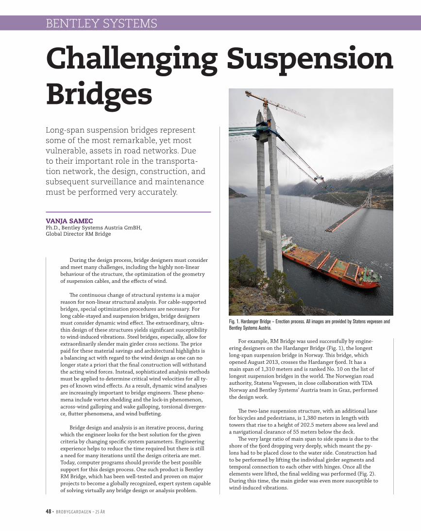
For example, RM Bridge was used successfully by engine-ering designers on the Hardanger Bridge (Fig. 1), the longest long-span suspension bridge in Norway. This bridge, which opened August 2013, crosses the Hardanger fjord. It has a main span of 1,310 meters and is ranked No. 10 on the list of longest suspension bridges in the world. The Norwegian road authority, Statens Vegvesen, in close collaboration with TDA Norway and Bentley Systems’ Austria team in Graz, performed the design work.
The two-lane suspension structure, with an additional lane
for bicycles and pedestrians, is 1,380 meters in length with towers that rise to a height of 202.5 meters above sea level and a navigational clearance of 55 meters below the deck.
The very large ratio of main span to side spans is due to the shore of the fjord dropping very deeply, which meant the py-lons had to be placed close to the water side. Construction had to be performed by lifting the individual girder segments and temporal connection to each other with hinges. Once all the elements were lifted, the final welding was performed (Fig. 2). During this time, the main girder was even more susceptible to wind-induced vibrations.
Long-span suspension bridges represent some of the most remarkable, yet most vulnerable, assets in road networks. Due to their important role in the transporta-tion network, the design, construction, and subsequent surveillance and maintenance must be performed very accurately.
VANJA SAMEC Ph.D., Bentley Systems Austria GmBH, Global Director RM Bridge
BENTLEY SYSTEMS
Challenging Suspension Bridges
Fig. 1. Hardanger Bridge – Erection process. All images are provided by Statens vegvesen and Bentley Systems Austria.
48 • BROBYGGARDAGEN – 25 ÅR

The bridge deck consists of an orthotropic steel box, with a width/depth value of 17.3 meters/3.2 meters. The stiffness of the main girder is relatively small when compared to other bridges of this span type. The distance between the two main cables is only 14.5 meters, which means that the Hardanger Bridge is one of the most slender bridges in the world (Fig. 3).
Among some of the specific challenges on this project were the highly non-linear behaviour of the structure; the need to optimize the geometry of the suspension cables while desig-ning the sag profile; the non-linear behaviour due to the traffic loading; and optimization of the erection procedure, wind loading, and wind-induced vibrations.
RM Bridge was used to calculate the cable lengths for the main cable and hangers by applying a set of constraints for sag and cable forces for the bridge in service state. The final geometry of the main girder is now straight but with a constant radius in elevation. This vertical radius is achieved by a constant bending moment induced between the pylons and the hangers closest to the pylons.
Numerical wind investigations of the main girder and pylons were performed with a CFD module that applies the vortex particle method to describe the air flow around the cross-section (Fig. 4). Additionally, small-scale wind tunnel measurements were performed in collaboration with the Vir-
tual Vehicle Competence Center (VIF) in Graz to calibrate the developed CFD module.
For the study, two variations of the girder were considered: one with the plain girder and one with attached wind guiding vanes and spoilers.
CFD calculations were performed for three different para-meter configurations of Reynolds number. Additionally, the calculation results were compared with a wind tunnel test with a 1:100 model of the cross section without guiding vanes and spoilers at a Reynolds number Re = 10e5.
Wind buffeting analysis was performed for a wind profile in which the mean wind is determined by a logarithmic distribu-tion and the power spectral density is of Kaimal type. By com-paring results for static wind only, static and dynamic lateral forces are of the same magnitude. The twisting moment is lar-ger for the dynamic wind. Due to the fluctuating vertical wind component, the effective wind incident angle varies more than static effects. Thus, the overall twisting of the deck is amplified and the internal moment is consequently higher (Fig. 5).
Future projects in Norway that will require innovative bridge and tunnel technologies, as well as experienced engi-neers and reliable software applications, include the E39 road between the cities of Kristiansand, Stavanger, Bergen, and Trondheim, which will become a ferry-free highway route.
Fig. 4. CFD calculation.
Fig. 2. Main cables.
Fig. 5. Static and dynamic (lateral wind) internal forces of the main girder
Fig. 3. Hardanger Bridge in August 2013.
BENTLEY SYSTEMS
BROBYGGARDAGEN – 25 ÅR • 49