Embed Size (px)
Citation preview

SUSPENSION BRIDGES
Roberto Crocetti

How does the tension in the cable vary withincreasing sag ”f”?

Design of cable
• Span: L• Total weight: q
Funicular of forces• Divide the uniformly distributed load into a sufficient number of segments
• Assign a force to each segment

Funicular of forces• Find vertical reactions

Funicular of forces• Find vertical reactions

O
• Choose a point “O”

• The maximum force in the cable can be obtained by measuring the segment O‐I:
iAB FF 5,8
AR
BR
sinA
ABRF Or:
iF
O
I
For a given cable cross section and strength, the position of “O” can be determined graphically

O
AB
C

O

The sag “f” is too big!
We want f≈L/10
How do we achieve a smaller sag?
O

Move the origin from “O” to “O’”
Note that doubling the distance between O and the vertical line the sag f is reduced by one half
However, the force in the cable has significantly increased!

Pag 3‐4‐5

Cable length

Example

Example
Some important properties ofcables

Cable subjected to uniformly distributed load
g
beamg
HM
y ,
2, 22
xgxlgM beamg
flgHg
8
2
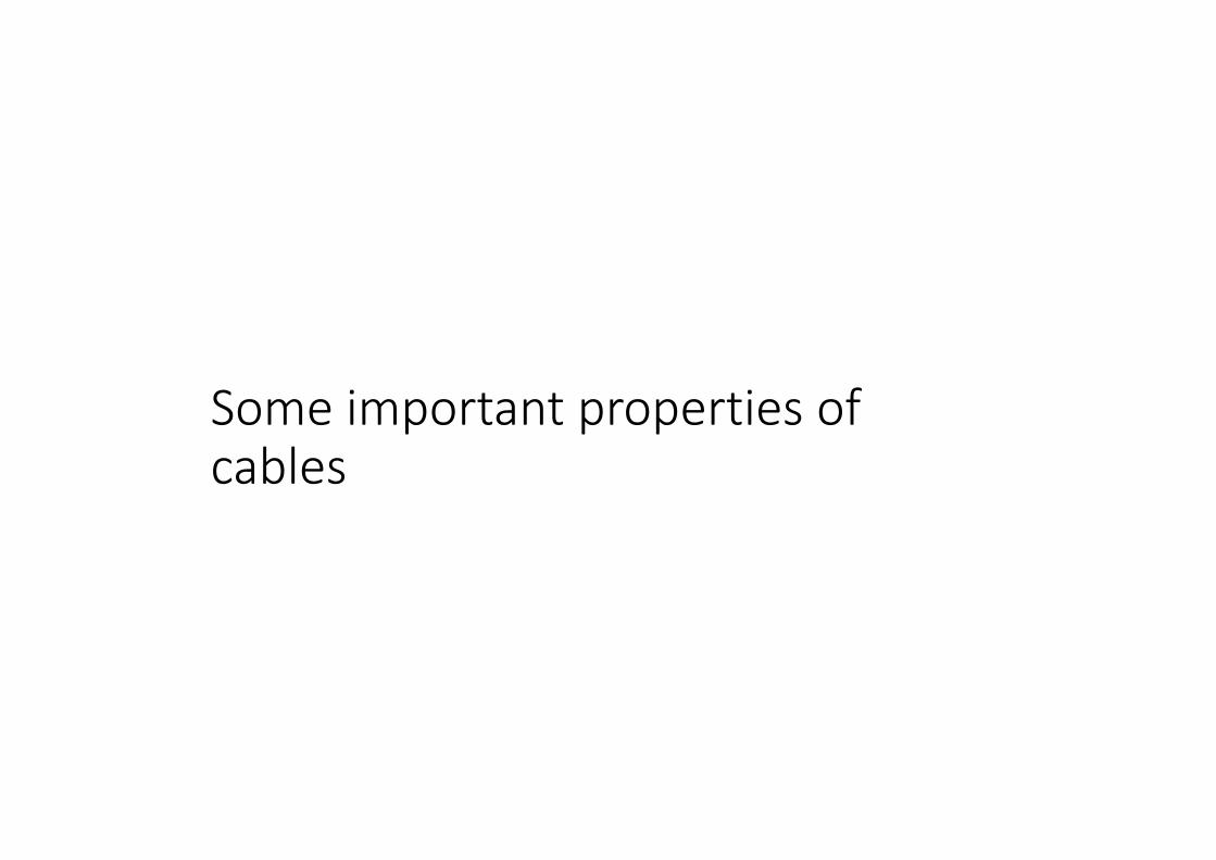
Deflection: larger self weight induce smaller deflection due to concentrated load!
∙lRatio between point loadand self‐weight (unif. distributed)

Influence of the bridge self‐weight on the deflection caused by a
concentrated load – a graphic‐staticsapproach
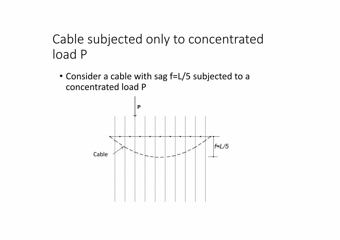
Cable subjected only to concentratedload P• Consider a cable with sag f=L/5 subjected to a concentrated load P
Cable

• Consider a cable with sag f=L/5 subjected to a concentrated load P
Cable afterloading
Cable subjected only to concentratedload P
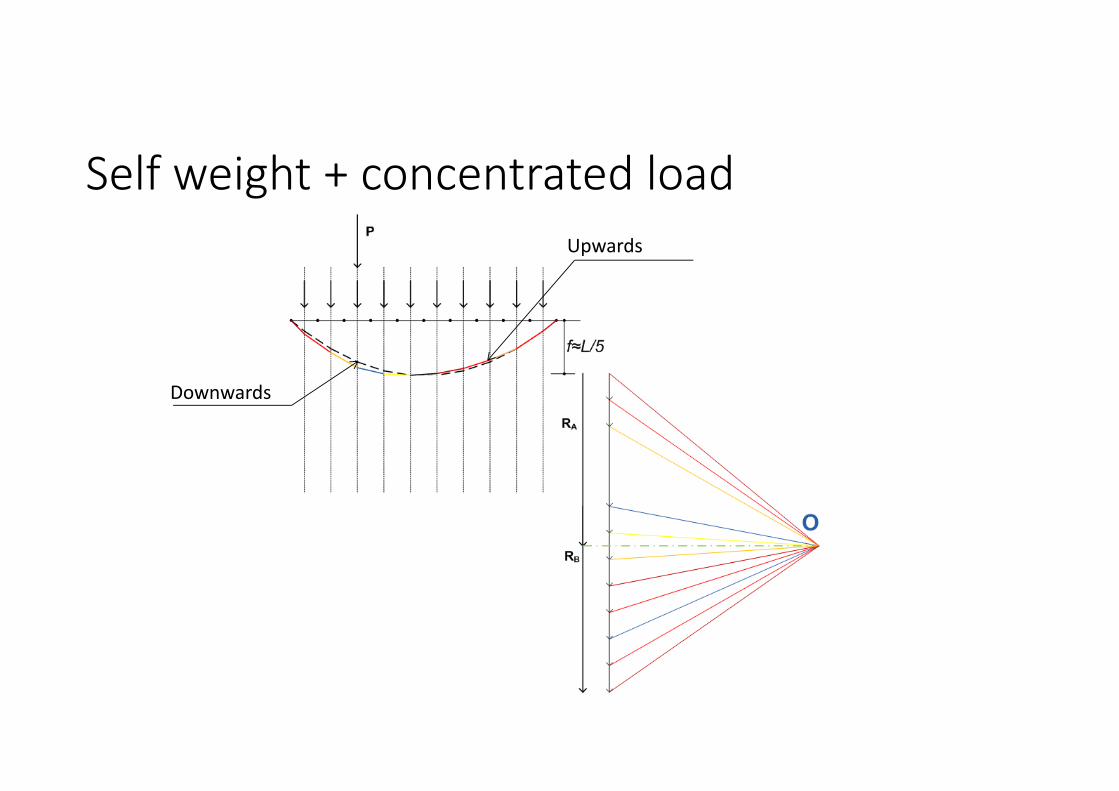
Self weight + concentrated load
Downwards
Upwards

Comparison

Which is the position of the concentred load that produces the maximum deflection of the cable?

Deformation of the cable for different positions of ”Q” (analitically derived curves)
∙l
Ratio betweenpoint load and self‐weight (unif. distributed)
Position of ”Q” for maximum deflection (1/5 ofthe span)

How can we increase the stiffness of a cable?
in other words
how can we reduce de verticaldeflection of a cable caused by a pointload?

Methods to reduce the deformation of cable structure
Pre‐stress the hangers
Cable with a certain bending stiffness (beam/cable)
Increase self‐weight
Use a stiffer stiffening girder which can redistribute the concentrated load

What is the effect of the self weight?
Larger self‐weight induce larger tension “T” in the cable. “T” can be regarded as a pre‐stressing force.
The higher the pre‐ stress force, the stiffer is the cable (compare to a guitar string)

Light deck (small pre‐stress in the cable)
Large deformations to concentrated load
Heavy deck (large pre‐stress in the cable)
Small deformations to concentrated load
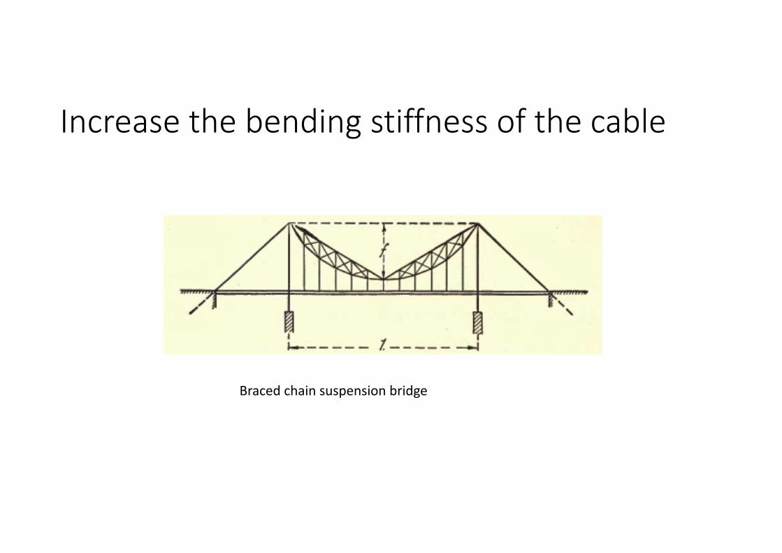
Increase the bending stiffness of the cable
Braced chain suspension bridge

Increase the bending stiffness of the cable
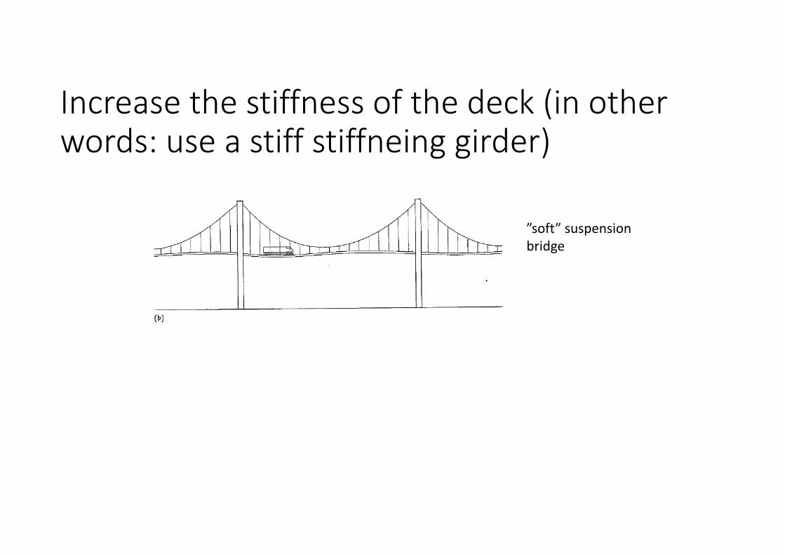
Increase the stiffness of the deck (in otherwords: use a stiff stiffneing girder)
”soft” suspension bridge

Increase the stiffness of the deck (in otherwords: use a stiff stiffneing girder)
suspension bridge with stiffeninggirder
If the deck is stiff enough, the shape of the cable remains a parabola under loading. This means that the cable must be subjected to uniformlydistributed load!

Suspension bridges with stiffening girder• The stiffening girder transforms the concentratedload into a distibuted set of equal vertical pullsthat are compatible with the shape of the cable
• All the differences between the actual loading and the loading that corresponds to the shape of the cable are absorbed by the beam

• Show example

Bending moment in the stiffneinggirder
Notice that most of the self weight is taken by the cable!

Structural analysis of suspension brides

Real situation: Interaction between cable and deck
Sketch: B. Åkesson
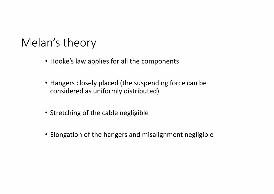
Melan’s theory• Hooke’s law applies for all the components
• Hangers closely placed (the suspending force can be considered as uniformly distributed)
• Stretching of the cable negligible
• Elongation of the hangers and misalignment negligible

Simplification
Sketch: B. Åkesson

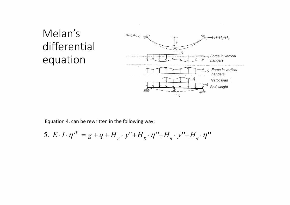
Melan’sdifferential equation
"".1 beamQg MyHH Cable force equilibrium:
Derivate two times:
syHH Qg ''''.2
qxM
2
2
Remember that:

Melan’sdifferential equation
sqgIE IV .3Differential equation for the girder:
Put 2. in 3.: syHH Qg ''''.2
''''.4 yHHqgIE QgIV
Melan’sdifferential equation
''''''''.5 qqggIV HyHHyHqgIE
Equation 4. can be rewritten in the following way:

Melan’sdifferential equation
It can be assumed that the cable carries the self‐weight alone (i.e. the girder is not contributing to carry the self weight)
gyHMyH ggg ''.6
Put 6. in 5.:
''''
''''''.7
yHHHqIE
HyHHgqgIE
qqgIV
qqgIV

yHHHMM qqgq .8
Or integrating Eq. 7 two times:
M: Bending moment in the girder
Mq: Bending moment due to “q” acting on a simply supported beam

Note that for slender girders (i.e. EI/Lsmall) the equation of the cable alone leads to similar results as the Melan’sequation

Suspension bridge components
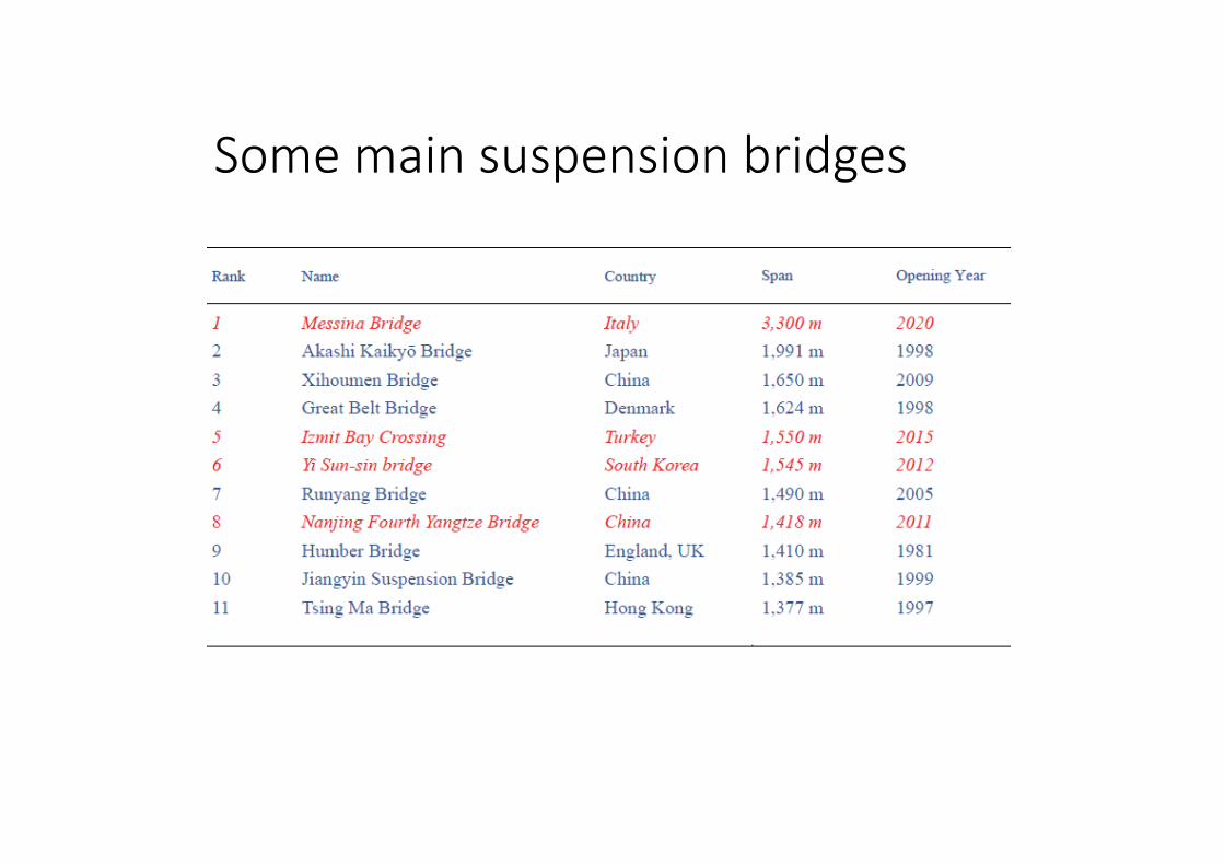
Some main suspension bridges

Akashi Kaikio Bridge, Japan 1991m
Cable diameter ca 1,2m


Will open for traffic in June 2013

Hardanger Bridge
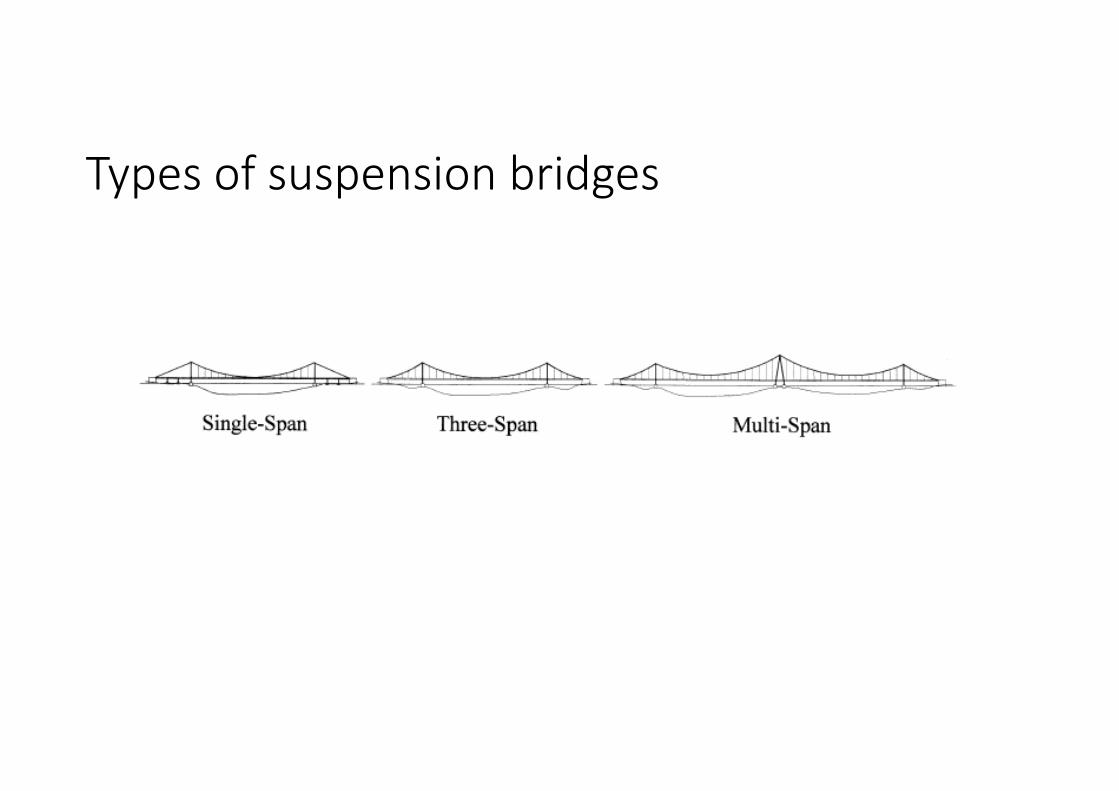
Types of suspension bridges

Types of stiffening girders

Types of suspenders/hangers

Example: Severn bridge (UK)
‐ the bridge becomes more rigid (» 25%), due to the truss behaviour
‐ reduced tendency to oscillate (flutter).
‐ However, the constantly changing forces in the hangers can create fatigue problems

Type of anchoring
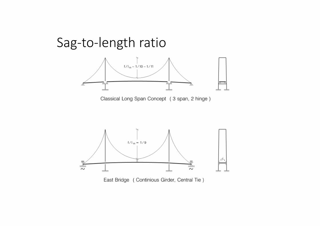
Sag‐to‐length ratio

Great Belt suspension bridgeGreat Belt suspension bridge

Great Belt Bridge, Overview
Total length: 6.8 km

Let us study the different parts/components of a suspension bridge

Towers/Pylons
• Rigid towers for multispan suspension bridges to provide enough stiffness to the bridge
• Flexible towers are commonly used in long‐span suspension bridges, ‐
• Rocker towers occasionally for relatively short‐span suspension bridges.

Some common tower types

The pylons, Hardanger Bridge

Great belt Bridge, Pylon
• Height above sea level: 254 m
• Legs at top: 6.5 m x 7.5 m
• Legs at base: 14 m x 15 m
• Caisson: 78 m x 35 m
• Wall thickness of legs: 1.7 m
• Concrete per pylon: 51,250 m3

Common stiffening girder

Great belt Bridge, Girder
• Total length: 2,694 m
• Length of sections: 48 m

The stiffening girder, Hardanger Bridge

Messina strait bridge, closed box girder

Cables
• A cable is a highly flexible member
• A cable transmits primarily axial forces
• A cable can be made of : • a bundle of steel wires• A bundle of strands• A boundle of several cables

Wires• Are produced from high‐strength steel bars by rolling or cold drawing (the initial area is reduced)
• The cold‐forming process results in‐ an increase in the tensile and yield stress and‐ a decrease in the ductility of the
Diametre 1‐7 mm

Wires
• The optimum wire diameter is 5,0‐5,5mm
• A larger diameter makes the wire too stiff
• A smaller diameter requires more wires and more labour.
• The wire material has an ultimate strength up to 1600 ‐ 1800N/mm2

Strand• is produced from a series of wires that are wound together in a helical, parallel or Z‐lock fashion

Cables/ropesParallel wire cables are composed of a series of parallel wires
Strand cables are composed of parallel or helically combined strands
Locked‐coil cables (which were invented for better corrosion protection). These cables are less flexible than the othertypes.

Types of cables
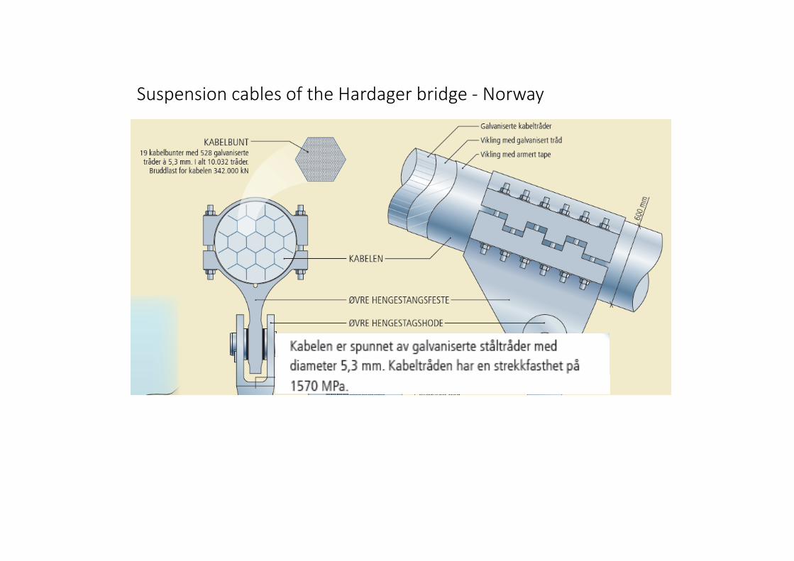
Suspension cables of the Hardager bridge ‐ Norway

Hanger cable of the Hardager bridge ‐ Norway

Hangers and suspension cables of the Hardager bridge ‐ Norway

Mechanical properties of cables• the tensile strength of the wires is high (it is also normally inversely proportional to the wire diameter). Normally fu= 1500‐1800 N/mm2.
• The diagram for this steel has no yield plateau and so the yield strength is conventionally defined as the stress at which the plastic deformation is 0,2%. fy= 80 to 90% of fu
• The modulus of elasticity of cables is generally smaller than that of the steel material (wire) of which they are composed

Stiffness of cables
• For parallel wire cables E = 200 N/mm2
• For locked‐coil cables E = 160 N/mm2
• For strand cables E = 150 N/mm2

Design values for cables (check producers web‐page)
Fu = ks Am . fuThe tensile resistance of a cable is:
Am is the “metallic area”of a cable:
ks = 0,76 – 1,0
f = 0,55 – 0,86
The design tensile resistance is
FRd = Fu /M (M = 2,0 for cables)
d=cable diameter

Main Cables Great Belt bridge ‐ DK
strand

Connections cable‐hanger and girder‐hanger

Cable and hangers, Hardanger Bridge

Attaching the cables –socketed fitting
The end of the cable is broomed into individual starnds

Attaching the cables –socketed fitting
The broomed end of the cable is then inserted into a conical steel basket
Molten zinc is poured into the basket to embed the wires and make the attachment


Connections

A preliminary sketch of details for a relatively small cable structure (cable, mast and foundation)

Saddles

The tower saddle, Hardanger Bridge

Cable anchorage – Severn bridge (UK)

The anchor block, Hardanger Bridge
19 strands anchoredto the anchoringdevise

The anchor block, Hardanger Bridge

Great belt Bridge, Girder Aerodynamics

Wind tunnel studies