Embed Size (px)
Citation preview
Detection of Partial Discharge in High Voltage Power Equipment under
Sinusoidal Applied Voltage
A thesis submitted in partial fulfillment of the requirements for the award of the degree of
Bachelor of Technology
by
NEERAJ SETHI
(Roll No: 111EE0615)
May-2015
Department of Electrical Engineering
National Institute of Technology, Rourkela
Rourkela-769008, India http//:www.nitrkl.ac.in
Detection of Partial Discharge in High Voltage Power Equipment under
Sinusoidal Applied Voltage
A thesis submitted in partial fulfillment of the requirements for the award of the degree of
Bachelor of Technology
by
NEERAJ SETHI (Roll No: 111EE0615)
May-2015
Under the Guidance of
Prof. S. KARMAKAR
Department of Electrical Engineering
National Institute of Technology, Rourkela
Rourkela-769008, India http//:www.nitrkl.ac.in

National Institute Of Technology
Rourkela
CERTIFICATE This is to certify that the thesis entitled, “Detection of Partial Discharge in High Voltage
Power Equipment under Sinusoidal Applied Voltage” submitted by Mr. Neeraj Sethi in
partial fulfillment of the requirements for the award of Bachelor of Technology Degree in
Electrical Engineering with specialization at the National Institute of Technology, Rourkela
(Deemed University) is an authentic work carried out by her under my supervision and
guidance.
To the best of my knowledge, the matter embodied in the thesis has not been submitted to
any other University / Institute for the award of any Degree or Diploma.
Date: Prof. S. Karmakar
Department of Electrical Engineering
National Institute of Technology
Rourkela-769008

ACKNOWLEDGEMENTS
On the submission of my thesis report of “Detection of Partial Discharge in High Voltage Power
Equipment under sinusoidal applied voltage”, I would like to extend my gratitude & my sincere
thanks to my honorable supervisor Prof. S. Karmakar, Department of Electrical Engineering
for his inspiration and moral support during the course of my work in the last one year. I truly
appreciate and value of his esteemed guidance and encouragement from the initiation period to
the completion period of this thesis work.
I extend my sincere thanks to all faculty and non-faculty members of the Department for
their help directly or indirectly, during the course of my thesis work.
Last but not the least, I would like to give sincere thanks to all of my friends who have
patiently extended all sorts of help, taught the value of hard work and inspired me a lot. They
rendered me enormous support being apart during the whole tenure of my stay in NIT Rourkela.
Date:
Place: (Neeraj Sethi)
CONTENTS
Page No. Abstract i
List of Abbreviation ii
List of Symbols iii
List of Figures iv
List of Tables V
Chapter 1. Introduction 1
1.1 Introduction 1
1.2 Literature review 1
1.3 Motivation and objective of the Thesis 3
1.4 Organization of the Thesis 4
Chapter 2. C of Partial Discharge (PD) 5
2.1 Partial discharge (PD) 5 2.2 Requirement of detection PD 5
2.3 Classification of PD 6
2.4 Effect of PD in insulating system 9
2.5 PD detection methods 9
2.6 Factor influencing the dielectric strength of insulator 11
2.7 Role of apparent charge 13
Chapter 3. Mathematical modeling of partial discharge 14 3.1 Analyzing of void parameter 14 3.2 Circuit model for PD measurement 15
3.3 Partial discharge measurement system 15
3.4 Electrical circuit illustration for PD measurement 17
3.5 Simulink model descriptions for detection of partial discharge 18
Chapter 4. Results and Discussions 21
Chapter 5. Conclusion and Scope for the Future Work 27 5.1. Conclusion 27 5.2. Scope for future work 28
References 29

ABSTRACT
In high voltage (HV) electrical power system, for the protection of high voltage power
equipment to protect incipient failure one require proper insulation. For the insulation solid,
liquid and gaseous form materials are used. There is no ideal insulating Material in real life that
is flawless, in actually, and contains impurities. The biggest affecting impurities in the
insulating materials is the presence of air bubble and deeply undesirable for such type of bad
insulation which makes a local weak zone inside the insulator. The High Voltage equipment
insulation gradually degrades due to cumulative effect of electrical, chemical and thermal stress
inside the insulator. Due to the degradation a high voltage stress creates which causes the weak
zone inside the insulator. The partial discharge is the result of cumulative collection of all these
phenomena. Finally the insulation properties of these materials is excessively degrades its
quality. In this work a simulation model investigation of insulating material transformer oil has
been finished. Transformer oil as a liquid insulator are taken for acknowledgement of real Pd
action inside the insulators with the use of high voltage utilizing the point-plane electrode
arrangement. Electrical equipment model of the insulation has been done using MATLAB
SIMULINK with a cylindrical void which is impurity. In addition, the relationship between the
induced charge and void parameter is discussed for cylindrical void.
Page No. i

LIST OF ABBREVIATIONS IEC standard International Electro Techno Commission PD Partial Discharge HV High Voltage MI Measuring Instrument PRPD Phase Resolved Partial Discharge DGA Dissolve Gas Analysis
Page No. ii

LIST OF SYMBOLS
Symbols Symbols Name
R Radius related to void
D Distance between the electrodes
H Height related to void
ε0 Permittivity of free space
εr Relative permittivity of dielectric
Ei Inception voltage
El Limiting field related to ionization
V Volume of cylindrical void
Q Apparent charge
Ck Coupling capacitor
Ct Capacitance related to object to test propose
Cc Capacitance of void
Cb capacitance of the remaining series connected insulation with void (Cc)
Ca capacitance of the remaining discharge-free insulation of the rest of the
Insulator
Rm Resistance of measuring system
Page No. iii

LIST OF FIGURES
Figure No. Figure Title Page No.
Figure 2.1 Types of partial discharge (a) Corona Discharge 8
(b) Surface discharge, (c) Treeing
Channel (d) Cavity discharge
Figure 3.1 Cylindrical void model inside dielectric 15
Figure 3.2 Electrical identical circuit model of cylindrical void alongside 17
high voltage hardware
Figure 3.3 Simulink Diagram for PD measurement with 5 kV between object 20
Figure 4.1 The relation between apparent charge and height of the void 21
Figure 4.2 A linear relationship of volume of void with apparent charge 22
Figure 4.3 The relationship of diameter of void with apparent charge 23
Page No. iv

CHAPTER-1
INTRODUCTION
Introduction
Literature analysis
Motivation and objective
Organization

Chapter-1
INTRODUCTION
1.1. INTRODUCTION The quality of insulation has a great deal in high voltage power engineering. Various types of
materials are utilized and formed together for making insulation useful in HV devices. Insulation
gets worse due to electro-mechanical stresses and strains by partial discharge. Some impure
insulation forms causes a lot of ill effects. Cause of these unrequired substances air bubbles get
formed and placed in the insulation region and this makes partial discharge visible. Insulation
breakdown is manipulated responsibly by different engineers. In high voltage device partial
discharge generally takes place in gaps that makes material good to worse conductors. Due to
these problems partial discharge calculation and handling is necessary for foreseeing of
insulation breakdown to get a long period performance of high voltage power equipment.
1.2 LITERATURE REVIEW In the start of the previous era, where these high voltage devices or revolutions took place for
power production supply system. Partial discharge have been known or understood as a danger
for insulation [1-25]. In this present era a lot of experiments took place for further understanding
and knowledge of various scientists gave different presentation about tacking it. [1-2]. One
Author Van Brunt showed his thesis on the emphasis of memory effects in partial discharge in
1994 [2]. Paithankar and Mokashi founded a method for anomaly detection on mathematics in
1997 [4].
Page No. 1

Detection of partial discharge in High Voltage Power Equipment under sinusoidal applied voltage
In the knowledge of various authors partial discharge is a haphazard process. It is a nonlinear and
random system. Partial discharge identification and analysis method is for preventing high
voltage devices from insulation failure and availability of partial discharge is the solo reason for
insulation dielectric damage ad failure. They have showed their patents and created a small
module of partial discharge of combined analysis mode with the help of common test programs
like PSPICE, MATLAB SIMULINK. Some scientists designed a visible virtual design and
showed a study of epoxy resin envelop only one ad two pits [6].
Numerous strategies have been proposed in the writing to gauge the amount of pollutants
stored on an insulator surface, for example, estimation of proportionate salt deposit density,
determination of nonsalable deposit thickness, and estimation of surface resistance [7 - 16].
Some tells that analysis and calculation of partial discharge on regard of the synthesis of partial
discharges. Some showed virtual nonlinear analysis in real time design of transformer and PRPD
analysis. Using a software called PDGold for identification of the φ-q-n design. An author has
created a real time control strategy by using ICT facilities enabled ORMPD [17 - 25].
Page No. 2
Detection of partial discharge in High Voltage Power Equipment under sinusoidal applied voltage
1.3. MOTIVATION AND OBJECTIVE
The visibility of partial discharge is a danger sigh for the insulation breakdown in high
voltage devices. As we know that the insulation devices management is a careful strategy, so the
standard of insulation devices are crucial play in high voltage devices. We have understood that
these are made without caring about about the soupcon of impurity in the core of insulators. The
distance of insulator are of various types and structure in the production process only it known
that generally hard insulator casings are less pure like air circular balloons which are created in
the interior side of insulators in tiny places. The destruction of protection places is due to the
availability of partial discharges. It is basically controlled and handled by easily placing though
high power engineering works. Basically in the high voltage devices the protection casing hard
insulator breakdown or damage place due to availability of some partial discharge in the deep
core of pit samples. Due to its presence PD analysis and calculation is very important for
successful handling and longevity of insulation in those devices.
The main objective of the thesis is
To get relationship between the void which are the causes of appearance of PDs activities.
To get the partial discharge functioning in the pit executed with the Transformer oil
To get the detection of PD activity inside the Transformer oil in high voltage power Equipment .
Page No. 3

Detection of partial discharge in High Voltage Power Equipment under sinusoidal applied voltage
1.4 ORGANISATION The whole work Chapter in five different domains including introduction are Chapter 1: Basic understanding of the idea of the concerned work, it undertake all the things
works ad review on partial discharge characteristics as well as manipulation of the
Thesis. Chapter 2: This defines some normal understanding of partial discharge like the importance ad
identification of partial discharge in HV devices, its differentiation, and its
management different factors responsible for the hard casing and its significance
for PD calculation. Chapter 3: This describes the mathematical representation of partial discharge in the core of
hard insulating casing. We represent it by equivalent circuit representation of partial
discharge by MATLAB/SIMULINK representation partial discharge calculation. Chapter 4: In this chapter calculated analytical record of the PD and various representation
developed by SIMULINK. This includes identification of partial discharge pulses,
cyclic ratios of the calculated output found from the PD pulses, characteristics
study on changing height and radius of void. Chapter 5: Summary of the whole thesis chart, its future aspect and all the assembled works
references.
Page No. 4
CHAPTER-2
OVERVIEW OF PARTIAL
DISCHARGE (PD)
Partial discharge (PD)
Requirement of detection of PD
Classification of PD
Effect of PD in insulating system
PD detection methods
Factors influencing the dielectric strength of insulator
Role of apparent charge
Chapter-2
Overview of Partial Discharge (PD)
2.1 PARTIAL DISCHARGE According to IEC (International Electrotechnical Commission) Standard 60270, Partial
discharge is a localized electrical discharge that only partially bridges the insulation between
conductors and which may or may not occur adjacent to a conductor [13]. As a rule partial
discharges are the result of nearby electrical stress focus in protection or on the surface of
insulation protection. Such electrical discharges are showed up as impulses i.e., different types of
voltage drive and current impulse having spam of significantly less than 1sec [13].
2.2 REQUIREMENT OF DETECTION (PD) Generally insulator are not in the true form or in totally pure form. Because of the availability of
air particles, bubbles impurities are made inside the insulating case, this then makes the so called
void region weak and the partial discharge got created. The main thing responsible for this is the
dielectric constant which is less than its neighbor. It breaks down insulation casing in high
voltage devices. Partial discharge queerly takes places voids. These discharge are also the reason
for breakdown. Because of these, finally breakdown happens in the main insulation body. So
partial discharge identification and analysis is very crucial for high voltage power supply.
Partial discharge begins with the pits or the pits encasing the hard insulation casing. The
basic and most important element is the pit for partial discharge. These discharge shorten the
path between them. It is also visible on the top of the various insulation substances. The visibility
of PD inside the insulating substance is generally started inside the air occupies pits inside the
dielectric. The sole objective for all of this is the stresses and strains of the various pits which is
minimum and generally low than its neighbor. For these problems the electrical pressure across
the pits is generally greater along its longitudinal path of dielectric. We have found that when
voltage exceed inception voltage of the gas inside the pit, the partial discharge actually occurs
than.
Page No. 5
Detection of partial discharge in High Voltage Power Equipment under sinusoidal applied voltage
2.3. CLASSIFICATION OF PARTIAL DISCHARGE One can divide Partial discharge into two parts
(a) EXTERNAL PARTIAL DISCHARGE
External partial discharge happens in the exterior of the high voltage power components.
Examples are overhead lines etc.
(b) INTERNAL PARTIAL DISCHARGE
Inner PD happens in the inside of the entire body. The Partial discharge in the pit respects to
different classes of partial discharge and essential in computing PD. PD can be figured by
different routines as per the sorts. The basic standard of computation of PD is creation or use of
distinctive manifestations of vitality like light and so forth framework .The discharge in void is
having a place with such sort of partial discharge and fundamental for PD estimation framework
.PD estimation framework gives the data about the properties of protecting material utilized as a
part of high voltage power types of gear.
This specimen thing likewise includes diverse types of discharge, some of them are surface
release, corona, cavity release [2, 13].
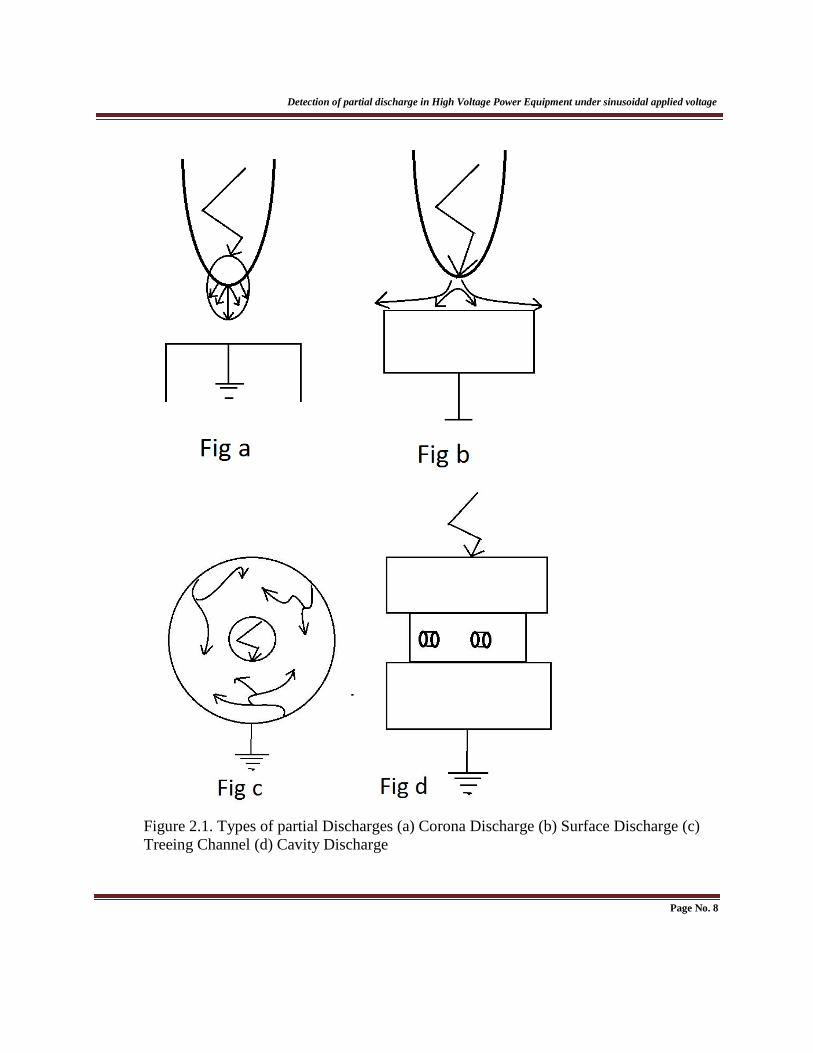
(i) Corona discharge: Corona discharge happens because of non-consistency of electric
field on sharp sides of conductor related to HV. The insulation supplied for such sort
of release is gas or air or liquid [2]. Such kind of discharge shows up for a long
length of time around the bare conductor. They are not assaulting specifically to the
insulating framework like inner and surface discharge. Just by the circuitous activity
of ozone shaped by corona decays insulating materials utilized.
(ii) Surface discharge: Surface discharge happens on reaction of dielectric material, for
example, gas/strong interface as ends over focused times the stress on material
.
Page No.6

Detection of partial discharge in High Voltage Power Equipment under sinusoidal applied voltage
This may happen in bushing, end of link, any point on insulator surface between
terminals. The presence of such discharge relies on upon different variables, for
example, as Permittivity of the dielectric material
Voltage difference between conductors
Properties of the insulation
(iii)Treeing channel: High power fields are delivered in an insulating material at its
sharp edges and it disintegrates the insulating material .That is in charge of
generation of persistent partial discharge.
(iv) Cavity discharge: The cavities are by and large framed in solid or liquid insulating
materials. The cavity is by and large loaded with gas or air. At the point when the
gas in the pit is over focused on such discharges are occurring.
Page No. 7
Detection of partial discharge in High Voltage Power Equipment under sinusoidal applied voltage
Figure 2.1. Types of partial Discharges (a) Corona Discharge (b) Surface Discharge (c)
Treeing Channel (d) Cavity Discharge
Page No. 8

Detection of partial discharge in High Voltage Power Equipment under sinusoidal applied voltage
2.4. EFFECT OF PD IN INSULATING SYSTEM
Presence of PD is the fundamental purpose behind debasement of insulating material and in
charge of happening of electrical breakdown. The event of reiteration rate of discharge is the
explanation behind mechanical degradation of the insulating material. The impact of release on
high voltage power equipment is serious to the insulation framework. Insulation harm happens
because of appearance of PD. The conductivity property of the insulation ascents because of
substance changes in the dielectric. By and large insusceptibility of inorganic dielectrics is more.
Porcelain, glass, mica are having a place with such dielectric. Polymer dielectrics are having a
place with natural dielectrics.
By and large, PD creates vitality as warmth. Heat vitality is the fundamental purpose
degradation of the protection. This impact is known as thermal impact on insulating materials
utilized. For high voltage power supplies, the decay of the protection can be known by checking
the PD exercises. PD movement ought to be checked time to time by the power engineer or power
manager at the season of assembling. 2.5. PD DETECTION METHODS There are different systems are investigated for the PD estimation in view of both electrical and
non-electrical phenomena. The strategies which have been prominently known for PD
measurement are,
(i) Optical detection method
(ii) Acoustic detection method
(iii) Chemical detection method
(iv) Electrical detection method
Page No. 9

Detection of partial discharge in High Voltage Power Equipment under sinusoidal applied voltage
2.4.1. OPTICAL DETECTION METHOD In optical detection system light is scattered as ionization, excitation process amid the presence
of discharge. The outflow of light is subject to the insulating medium utilized and different
parameters like temperature, pressure kind of insulating material is appropriate for this detection
strategy. So some trouble emerges in the event of execution in high voltage transformers because
of opaque nature of mineral oil.
2.4.2. ACOUSTIC DETECTION METHOD In acoustic detection strategy, acoustic sensors are set outside of the HV hardware for discovery
of PDs [10, 11]. The acoustic system is successful for seeing and encoding the acoustic Signal
created amid a partial discharge occasion. Acoustic routines have numerous points of interest
over different systems. Acoustic system is unaffected to electromagnetic interference (EMI),
which can diminish the affectability of electrical strategies [11]. The constraint of this
identification technique is the way of acoustic wave spread is confused because of the utilization
of non-homogeneous gadget like high voltage transformer. This technique is broadly relevant for
discovery of the different sorts of PD, discovering the area of insulation disappointment. The
trouble emerges behind this strategy is necessity of sensitivity.
2.4.3. CHEMICAL DETECTION METHOD In the chemical detection strategy, PDs are distinguished by watching the chemical changes in
the arrangement of protecting material utilized as a part of HV force hardware. In this system,
the dissolve gas analysis (DGA) and high performance liquid chromatography (HPLC) are
broadly utilized for PD determination. DGA gives the data of discharge regarding the volume of
gas created and HPLC measures the by items, for example, glucose and corrupted types of
glucose delivered [10, 11]. Some downside emerges in this substance identification technique,
for example, it doesn't give the data about the attributes of PDs and area of PDs.
Page No. 10
Detection of partial discharge in High Voltage Power Equipment under sinusoidal applied voltage .
2.4.4. ELECTRICAL DETECTION METHOD Electrical recognition strategy is a standout amongst the most famous strategies in HV power
system for PD estimation. In this work, electrical detection strategy has been utilized to reenact
the estimation of PDs in the model using transformer oil as an insulator. It concentrates on
appearance of the current and voltage pulse made by the current streamer in the impurities [10].
The beats are under one second and variety of recurrence segments in the scope of KHz, The
state of the pulse and event of phase location inside the ac cycle gives the data about kind of PD
and data about insulation failure. Time area recording gadget is utilized for perception of partial
discharge driving forces in this process of detection. This strategy is insulating material for
online electrical PD identification. Both broadband and narrow band electrical noise could be
found amid the operation of HV equipment. It is not simple to independent those electrical noises
and PDs. The defection which are gotten in this recognition technique rely on upon the geometry
of high voltage transformer. This technique has a few downsides however has wide application
in power plant which helps the power engineer by giving fundamental and critical data with
respect to the characteristic, appearance of changed sorts of PD and about the event of insulation
in high voltage power gear like transformer, link and so on.
2.6. FACTORS INFLUENCING THE DIELECTRIC STRENGTH OF INSULATING
MATERIAL The fundamental properties of the insulating materials utilized for high voltage power types of
equipment are:
1. Insulation resistance ought to be high.
2. Dielectric strength ought to be high.
3. Should have effective mechanical properties.
4. Materials ought to be unaffected by other chemicals.
Page No. 11
Detection of partial discharge in High Voltage Power Equipment under sinusoidal applied voltage
It is studied over that a few components or conditions make impact on dielectric quality of
insulation. The dielectric quality of insulating material relies on temperature, impurities, and so
forth and some different variables are likewise in charge of it. A. TEMPERATURE
The capacity of the insulation is reliant on the working temperature. Higher the temperature, the
level of degradation ought to be high and lesser will be its life. The temperature has an impact on
the dielectric quality of insulating material. It relies on the sorts of materials utilized as a part of
the high voltage power supplies. One sample is desiring it is the impact of temperature in the
dielectric quality of dielectric material utilized as a part of force supplies. The utilized dielectric
medium utilized is transformer oil which is inhumane to the temperature. As the oil has lower BP,
the dielectric quality of the material utilized abatements because of formation of vapor air
bubbles. The temperature at which the force supplies work is in charge of degradation of
insulating material utilized. The attributes of quality of the material utilized and temperature at
which supplies work is inversely corresponding.
B. ELECTRODE AND GAP CONDITIONS Effective distance between electrodes makes high impact on partial discharge and thus influences
material properties. The breakdown quality of oil relies on its width, terminal shape and material
utilized for protection. The size and state of anodes are in charge of determination of the volume
of medium related to high electric anxiety. Increment in volume builds the debasement content
particles. More debasement particles substance brings down the breakdown voltage of the space
between terminals. C. IMPURITIES The vicinity of polluting influence will make an impact on insulating material which is utilized
as a part of force supplies. The quality of dielectric liquid utilized as a part of high voltage
transformer reductions to 70 % in view of the polluting influence substance like metal particle. D .OTHER FACTORS The dielectric quality of protecting material which is utilized as a part of power supplies is
influenced by different variables likewise i.e. thickness of the example and mugginess.
Page No. 12

Detection of partial discharge in High Voltage Power Equipment under sinusoidal applied voltage Thickness of the example is specifically relative to the dielectric quality of the insulating
material and surface condition like dampness is contrarily corresponding to the dielectric quality
of the material. It has been watched that
Dielectric quality increments with the increment in thickness of the example.
Dielectric quality reductions with the increment in moisture.
2.7. ROLE OF APPARENT CHARGE
Partial discharge is the sequences of dielectric breakdown of a little partition of a solid or a
liquid electrical insulation framework which is due to high voltage stress. Partial discharge inside
an insulating framework might possibly uncover any obvious releases as the release occasions
have a tendency to have a more sporadic character. The impacts of discharge inside links and
other high voltage hardware ought not to be dealt with gently as it can even prompt complete
failure. PD is an electrical release that can conceivably bring about major issues amongst HV
equipment. As the PD is not quantifiable specifically with the assistance of the apparent charge
technique PDs are identified and measured in high voltage power hardware. The apparent charge
is the vital amount of all PD estimation. The word clear was presented on the grounds that this
charge is not equivalent to the measure of charge by regional standards included at the site of
release or void [13]. As indicated by IEC standard 60270 (International electro techno
Commission), the definition of Apparent charge is given by “Apparent charge q of a PD pulse is
that unipolar charge which, if injected within a very short time between the terminals of the test
object in a specified test circuit, would give the same reading on the measuring instrument as the
PD current pulse itself. The apparent charge is usually expressed in Picocoulombs”. The
apparent charge can't be measured straightforwardly. To quantify apparent charge the measuring
instrument obliges some adjustment. As the partial discharge is profoundly relies on upon the
geometrical setup of the void vicinity. As the PD inside the power equipment is not specifically
quantifiable due to the PD sources are not open. To conquer the above issue an apparent charge
strategy is utilized for estimation of the PD movement.
Page No. 13

CHAPTER-3
MATHEMATICAL MODELLING OF PARTIAL
DISCHARGE
Analyzing of void parameter
Circuit model for PD measurement
Partial Discharge measurement system
Electrical circuit illustration for PD measurement
Simulink model description for detection for partial discharge
Chapter-3
Mathematical modeling of partial discharge
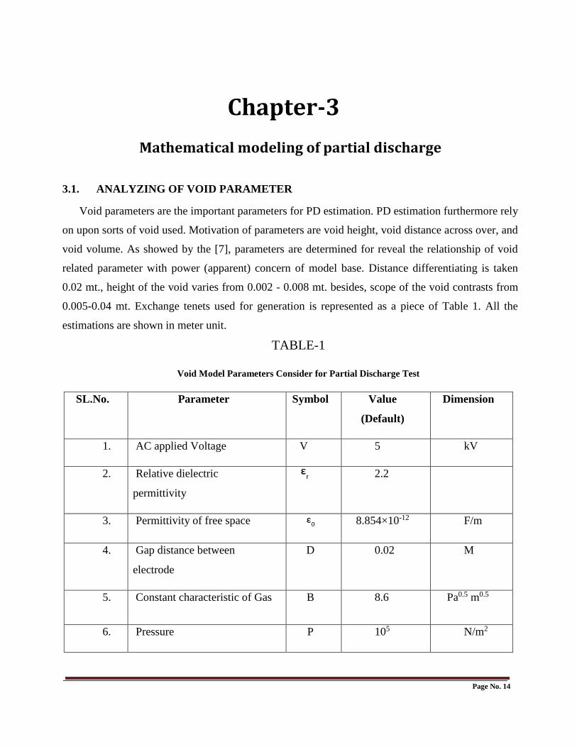
3.1. ANALYZING OF VOID PARAMETER
Void parameters are the important parameters for PD estimation. PD estimation furthermore rely
on upon sorts of void used. Motivation of parameters are void height, void distance across over, and
void volume. As showed by the [7], parameters are determined for reveal the relationship of void
related parameter with power (apparent) concern of model base. Distance differentiating is taken
0.02 mt., height of the void varies from 0.002 - 0.008 mt. besides, scope of the void contrasts from
0.005-0.04 mt. Exchange tenets used for generation is represented as a piece of Table 1. All the
estimations are shown in meter unit.
TABLE-1
Void Model Parameters Consider for Partial Discharge Test
SL.No. Parameter Symbol Value
(Default)
Dimension
1. AC applied Voltage V 5 kV
2. Relative dielectric
permittivity
2.2
3. Permittivity of free space 8.854×10⁻¹² F/m
4. Gap distance between
electrode
D 0.02 M
5. Constant characteristic of Gas B 8.6 Pa0.5 m0.5
6. Pressure P 105 N/m2
Page No. 14
Detection of partial discharge in High Voltage Power Equipment under sinusoidal applied voltage
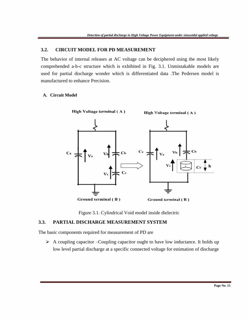
3.2. CIRCUIT MODEL FOR PD MEASUREMENT
The behavior of internal releases at AC voltage can be deciphered using the most likely
comprehended a-b-c structure which is exhibited in Fig. 3.1. Unmistakable models are
used for partial discharge wonder which is differentiated data .The Pedersen model is
manufactured to enhance Precision.
A. Circuit Model
Figure 3.1. Cylindrical Void model inside dielectric
3.3. PARTIAL DISCHARGE MEASUREMENT SYSTEM The basic components required for measurement of PD are
A coupling capacitor –Coupling capacitor ought to have low inductance. It holds up
low level partial discharge at a specific connected voltage for estimation of discharge
Page No. 15

Detection of partial discharge in High Voltage Power Equipment under sinusoidal applied voltage
Magnitude when coupling capacitor is joined in arrangement with the measuring
framework. A larger amount of PD is measured when coupling capacitor and
measuring Framework is joined independently. This happens when measuring
framework is associated in Arrangement with the test object.
A high voltage supply –High voltage supply is having low degree of background
Noise to pass the discharge magnitude which is to be measured for a particular
Applied voltage.
High voltage connection having sufficiently lower degree of background noise.
Input impedance for measuring system consisting of Rm, L, and C. Input impedance
is the most determinant factor for the wave shape of the PD impulse.
A high voltage filter- It is used for reduction of background noise from the power
Supply. Such filters are also used for improvement of voltage stability.
A test object- Consists of three capacitors. One capacitor is connected in parallel
with the two series capacitors
Cc corresponds to the cylindrical void present inside
the solid insulation
Test object
Cb corresponding to the capacitance of the remaining
series insulation with void(Cc)
Ca corresponds to the capacitance of the remaining
discharge-free insulation of the rest of the solid insulator
Measuring instrument -The measuring framework is utilized to recognize the
watched Electrical discharge from the test item.
Display unit and PC programming utilized for trademark study and its examinant.
Page No. 16
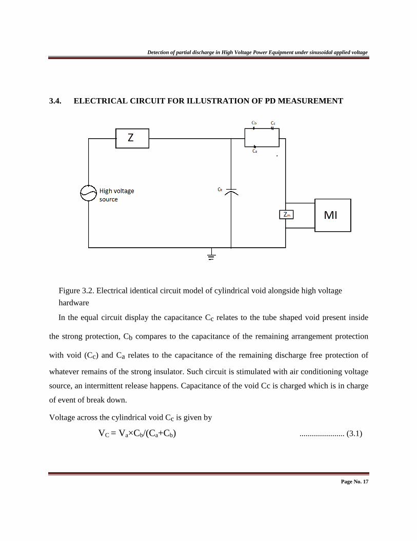
Detection of partial discharge in High Voltage Power Equipment under sinusoidal applied voltage
3.4. ELECTRICAL CIRCUIT FOR ILLUSTRATION OF PD MEASUREMENT
Figure 3.2. Electrical identical circuit model of cylindrical void alongside high voltage
hardware
In the equal circuit display the capacitance Cc relates to the tube shaped void present inside
the strong protection, Cb compares to the capacitance of the remaining arrangement protection
with void (Cc) and Ca relates to the capacitance of the remaining discharge free protection of
whatever remains of the strong insulator. Such circuit is stimulated with air conditioning voltage
source, an intermittent release happens. Capacitance of the void Cc is charged which is in charge
of event of break down.
Voltage across the cylindrical void Cc is given by
VC = Va×Cb/(Ca+Cb) ...................... (3.1)
Page No. 17
Detection of partial discharge in High Voltage Power Equipment under sinusoidal applied voltage
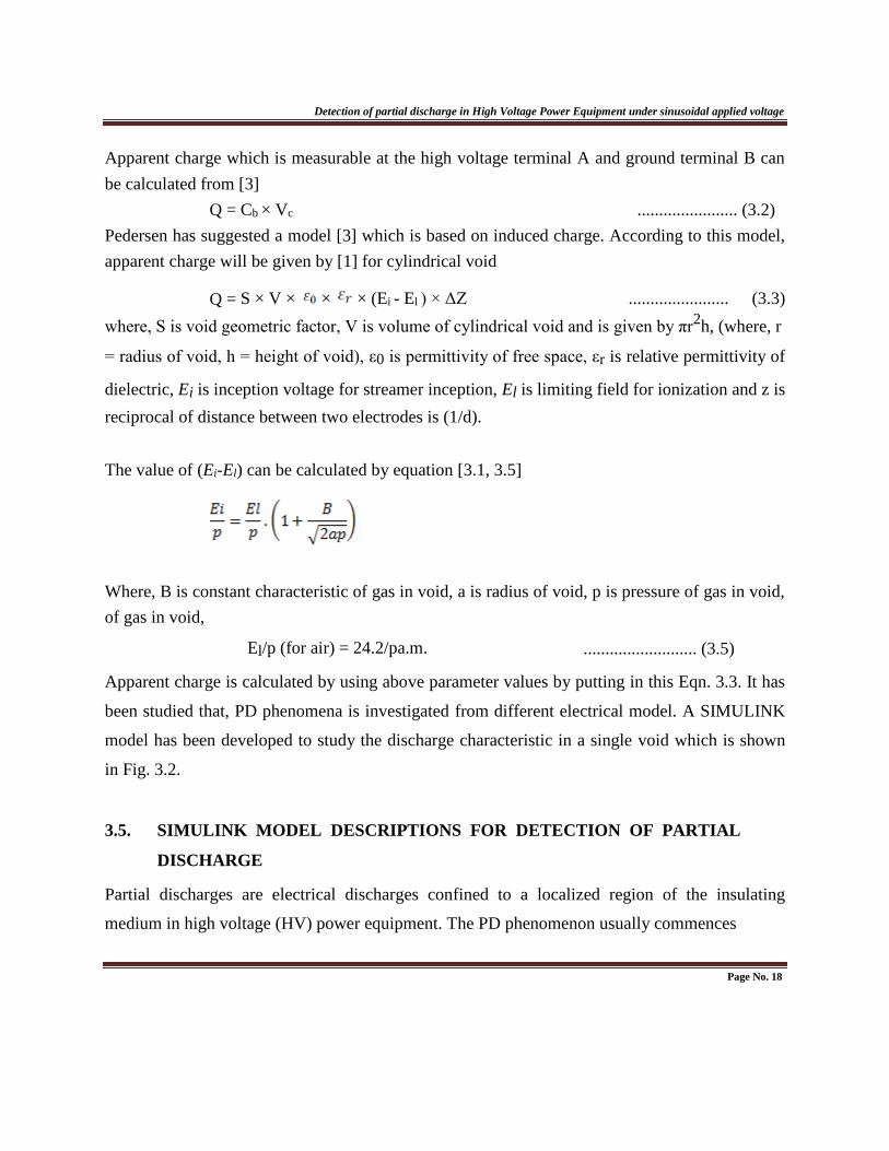
Apparent charge which is measurable at the high voltage terminal A and ground terminal B can
be calculated from [3]
Q = Cb × Vc ....................... (3.2)
Pedersen has suggested a model [3] which is based on induced charge. According to this model,
apparent charge will be given by [1] for cylindrical void
Q = S × V × × × (Ei - El ) × ΔZ ....................... (3.3)
where, S is void geometric factor, V is volume of cylindrical void and is given by πr2h, (where, r
= radius of void, h = height of void), ε0 is permittivity of free space, εr is relative permittivity of
dielectric, Ei is inception voltage for streamer inception, El is limiting field for ionization and z is
reciprocal of distance between two electrodes is (1/d).
The value of (Ei-El) can be calculated by equation [3.1, 3.5]
Where, B is constant characteristic of gas in void, a is radius of void, p is pressure of gas in void,
of gas in void,
El/p (for air) = 24.2/pa.m. .......................... (3.5) Apparent charge is calculated by using above parameter values by putting in this Eqn. 3.3. It has
been studied that, PD phenomena is investigated from different electrical model. A SIMULINK
model has been developed to study the discharge characteristic in a single void which is shown
in Fig. 3.2.
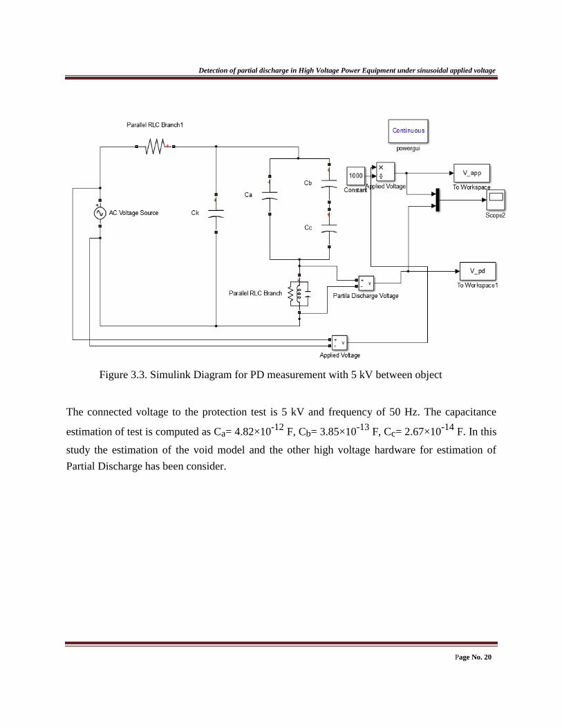
3.5. SIMULINK MODEL DESCRIPTIONS FOR DETECTION OF PARTIAL
DISCHARGE Partial discharges are electrical discharges confined to a localized region of the insulating
medium in high voltage (HV) power equipment. The PD phenomenon usually commences
Page No. 18
Detection of partial discharge in High Voltage Power Equipment under sinusoidal applied voltage
Inside the void, breaks, in void rises inside liquid dielectrics or consideration inside the strong
insulating medium. Also, PDs likewise happen at the limits between the distinctive insulating
materials, tainting, poor conveyor profiles and gliding metal-work in the HV gear [3-8]. The
electrical PD discovery system are in view of the presence of the PD current or voltage beat over
the test article for essential examination, which may be either a basic dielectric test item or
extensive HV power mechanical assembly. To assess the crucial amounts of PD pulse, a basic
proportionate capacitor circuit of strong insulator having barrel shaped void is thought seriously
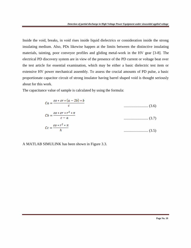
about for this work.
The capacitance value of sample is calculated by using the formula:
.......................... (3.6)
.......................... (3.7)
.......................... (3.5)
A MATLAB SIMULINK has been shown in Figure 3.3.
Page No. 19
Detection of partial discharge in High Voltage Power Equipment under sinusoidal applied voltage
Figure 3.3. Simulink Diagram for PD measurement with 5 kV between object
The connected voltage to the protection test is 5 kV and frequency of 50 Hz. The capacitance
estimation of test is computed as Ca= 4.82×10⁻¹²
F, Cb= 3.85×10⁻¹³
F, Cc= 2.67×10⁻¹⁴
F. In this
study the estimation of the void model and the other high voltage hardware for estimation of
Partial Discharge has been consider.
Page No. 20

CHAPTER-4
SIMULATION RESULTS
AND
DISCUSSION

Chapter-4
Results and Discussions
4. RESULTS AND DISCUSSIONS
To watch the PD movement because of vicinity of void inside the created strong protection
demonstrate a high voltage of 0-30 kV is connected in the middle of the anode. As the event of
the PD inside the force hardware is not straightforwardly quantifiable due to the PD sources are
not open a clear charge system is utilized. As indicated by IEC 60270 apparent charge „q‟ of a
PD pulse is that charge which if injected in a short time between the terminals of a test object in
a specified test circuit, would give the same reading on the measuring instruments as the PD
current pulse itself.
Figure 4.1.The relation between apparent charge and height of the void
Page No. 21
Detection of partial discharge in High Voltage Power Equipment under sinusoidal applied voltage It additionally mulled over that, clear charge is an essential element for PD estimation in the high
voltage power hardware. As the PD is very relies on upon the geometrical setup of the void
vicinity in the strong protection the connection between apparent charge and height of the void,
volume of the void and measurement of the void is considered in this study.
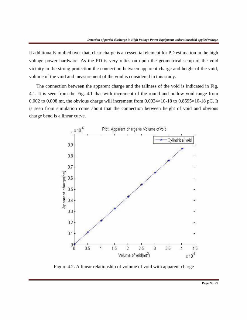
The connection between the apparent charge and the tallness of the void is indicated in Fig.
4.1. It is seen from the Fig. 4.1 that with increment of the round and hollow void range from
0.002 to 0.008 mt, the obvious charge will increment from 0.0034×10⁻¹⁸ to 0.8695×10⁻¹⁸ pC. It
is seen from simulation come about that the connection between height of void and obvious
charge bend is a linear curve.
Figure 4.2. A linear relationship of volume of void with apparent charge
Page No. 22
Detection of partial discharge in High Voltage Power Equipment under sinusoidal applied voltage
Another study has been done in this work which is the connection between the apparent
charge and the volume of the void. It is watched that the apparent charge is likewise a component
of volume geometry of the void structure. It is likewise watched that, the volume is
straightforwardly identified with obvious charge which is indicated in Fig. 4.2. It is seen from
simulation come about that the connection between void volume and apparent charge bend is a
straight one.
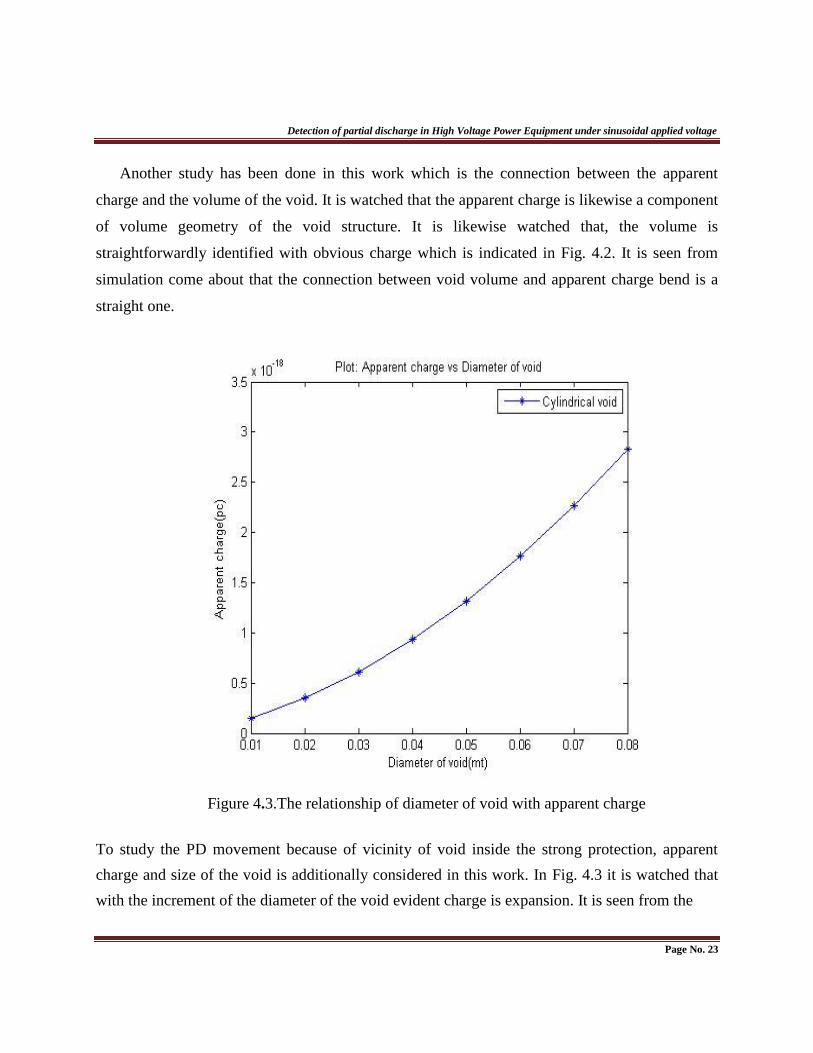
Figure 4.3.The relationship of diameter of void with apparent charge To study the PD movement because of vicinity of void inside the strong protection, apparent
charge and size of the void is additionally considered in this work. In Fig. 4.3 it is watched that
with the increment of the diameter of the void evident charge is expansion. It is seen from the
Page No. 23

Detection of partial discharge in High Voltage Power Equipment under sinusoidal applied voltage Fig. 4.3 the diameter of the cylindrical void changes from 0.01 mt.-0.08 mt. and comparing
estimation of the clear charge is changes from 0.034×10⁻¹⁸
to 0.8695×10⁻¹⁸
pC.
It is comprehend from the above result that the mean of the PD is likewise differ as the
apparent charge is shifting of changing the void distance across and void volume.
Page No. 24

Detection of partial discharge in High Voltage Power Equipment under sinusoidal applied voltage
Apparent charge is figured by utilizing above parameter esteem by putting in the Eqn.4.1.
The dimensional setup of void parameter influence the adjustments in the PD plentifulness while
5kV connected voltage is given between the two cathodes.
The amplitude value of the PD pulse can be determined by this equation
………………….(4.1)
Where, V represents the result of PD amplitude, q is apparent charge, Ck coupling capacitance,
.Therefore by increasing the height of the void
the PD pulse sufficiency is additionally increments as due to the apparent charge of the same
void is changes. Because of the change of the void height the void capacitance is likewise
changes which are delineated.
Page No. 25
And w is

Detection of partial discharge in High Voltage Power Equipment under sinusoidal applied voltage Further an examination has been made for vicinity of PD pulse over an aggregate measuring
period under applied voltage of 5 kV. Partial Discharge top worth changes with the sinusoidal
connected voltage. PD voltage goes Maximum to Minimum and can obtain values with the
variety in source voltage.
Page No 26

CHAPTER-5
CONCLUSION
AND
SCOPE FOR FUTURE WORK

Chapter-5
Conclusions and Scope for Future work
5.1. CONCLUSION
Partial discharges are a significant wellspring of protection failure in High Voltage Power
framework which needs to be observed constantly to evade the early disappointment in the
force framework system. The PD movement inside the liquid protection is profoundly relies on
upon the whole geometry of the void vicinity inside the liquid protection structure.
Furthermore, PD increments with the increment of connected voltage inside the Liquid
protection. Detachment of air bubble particles are exceedingly basic extensive protest because
of its impact which lessen the nature of protection and the estimation of Partial Discharge
Inception Voltage (PDIV).
.
Page No. 27

Detection of partial discharge in High Voltage Power Equipment under sinusoidal applied voltage
5.2. SCOPE FOR FUTURE WORK
A diverse kind of void structure has to be created to research the execution normal for PD
inside the distinctive dielectric medium.
Detection of the PD movement inside the HV power hardware with various detection
technique which helps the early determination of such high voltage power hardware for
their increments of lifetime and additionally the solid operation.
Frequency examination of PD utilizing the created structure.
On-line checking of the HV hardware utilizing defferent structure.
Page No. 28

REFERENCES
References
REFERENCE [1] G. C. Crichton, P. W. Karlsson and A. Pedersen, “Partial Discharges in Ellipsoidal and
Spherical Voids”, IEEE Trans. on Dielectric and Electrical Insulation, Vol. 24, No. 2, pp.
335-342, April 1989.
[2] R. J. Van Brunt, “Physics and Chemistry of partial discharges and corona”, IEEE Trans. On
dielectric and Electrical Insulation, Vol. 1, No. 5, pp. 761-784, October 1994.
[3] M. G. Danikas, “Some New Relationships and a Scaling Law Regarding Partial Discharges
in Spherical Cavities Enclosed in Solid Insulation”, Acta Electrotechnica Napocensis, Vol.
39, No. 1, pp. 5-9, 1998.
[4] A. A. Paithankar, A. D. Mokashi, “Can PD Phenomena be Analysed by Deterministic
Chaos?” EIC’97, Chicago, (IEEE) Conference proceedings, pp. 283-290, 1997.
[5] N. Kolev, P. Darjanov, E. Gadjeva and D. Darjanova, “Partial Discharge Phenomena
Simulation using General-purpose Analysis Program”, Proc of 6th IEEE International
Conference on Conduction and Breakdown in solid Dielectrics-ICSD 98, pp. 149-152, June
22-25, Vasteras, Sweden, 1998.
[6] C. Y. Ren, Y. H. Cheng, P. Yan, Y. H. Sun, T. Shao, “Simulation of Partial Discharges in
Single and Double voids Using SIMULINK”, Journal of Xi’an Jiatong University, Vol. 38,
No. 10, pp. 120-122, 2004.
[7] N. Kolev, P. Darjanov, E. Gadjeva and D. Darjanova, “An approach to develop a partial
discharge investigation”, Proc. of the IEEE Electrical Insulation Conference and Electrical
Manufacturing and Coil Windings conference, pp. 507-510, Chicago, 1997.
[8] L. Satish, and W. S. Zaengl, “Artificial Neural Networks for recognition of 3D Partial
Discharge patterns”, IEEE Trans. on Dielectrics and Electrical Insulation, Vol. 1, No. 2, pp.
265-275, April 1994.
[9] F. Gutleisch and L. Niemeyer, “Measurement and Simulation of PD in Epoxy Voids”, IEEE
Transaction on Dielectrics and Electrical insulation, Vol. 2, No. 5, pp. 729-743, 1995.
Page No. 29

References
[10] R. Bartnikas, “Partial Discharge their mechanism, Detection and Measurement”, IEEE
Trans. Electr. Insul. Vol. 9, pp. 763-808, 2002.
[11] L. E. Lundgaard, “Partial discharge. XIII. Acoustic partial discharge detection-fundamental
Considerations,” IEEE Electrical Insulation Magazine, 1992, 8(4): 25–31
[12] .S. Karmakar, N. K. Roy, P. Kumbhakar, “Partial Discharge Measurement of Transformer
with ICT Facilities”, Third International Conference on Power Systems, Kharagpur, India,
December 27 -29, 2009.
[13] S. Karmakar, N. K. Roy and P. Kumbhakar “Monitoring of high voltage power transformer
using direct Optical Partial Discharges detection technique”, journal of Optics, Vol. 38, No.
4, pp.207-215, 2009.
[14] E. Kuffel, W. S. Zaengl, J.Kuffel, High voltage engineering: fundamentals, Published by
Eleslever, ISBN 0-7506-3634-3, second edition, 2005.
[15] F. H. Krueger, Partial Discharge Detection in High Voltage Equipment, London, Boston,
1989.
[16] M. S. Naidu and V. Kamaraju, High Voltage Engineering, New Delhi, Tata McGraw-Hill,
pp. 69-85, 2004.
[17] Mu-Kuen Chen and C. Y. Cheng, “Proceedings of 2008 International Symposium on
Electrical Insulating Materials”, September 7-11, Yokkaichi, Mie, Japan, 2008.
[18] T. Krüger and R. Patsch, “Active Noise Reduction for Partial Discharge Measurement in
the Frequency Domain”, IEEE Bologna Power Tech Conference, Bologna, Italy, June 23th
26th, 2003.
[19] G. Chen and F. Baharudin, “Partial Discharge Modeling Based on a Cylindrical Model in
Solid Dielectrics”, International Conference on Condition Monitoring and Diagnosis,
China, April 21-24, 2008.
[20] C. Forssén and H. Edin, “Partial Discharges in a Cavity at Variable Applied Frequency Part
1 Measurements”, IEEE Transactions on Dielectrics and Electrical Insulation, Vol. 15,
No. 6, December 2008.
Page No. 30

References
[20] R. E. James and B. T. Phung, “Development of Computer-based Measurements and their
Application to PD Pattern Analysis”, IEEE Transactions on Dielectrics and Electrical
Insulation, Vol. 2, No. 5, October 1995.
[21] K. Wu1, T. Ijichi, T. Kato, Y. Suzuoki, F. Komori, T. Okamoto, “Contribution of Surface
Conductivity to the Current forms of Partial Discharges in Voids”, IEEE Transactions on
Dielectrics and Electrical Insulation, Vol. 12, No. 6, pp .1116-1124, December 2005.
[22] Q. Shaozhen and S. Birlasekaran, “The Study of PD Propagation Phenomenon in Power
Network”, IEEE Transactions on power delivery, Vol. 21, No. 3, pp.1083-1091, July 2006.
[23] Suwarno School of Electrical Engineering and Informatics, Institute Teknologi Bandung,
Indonesia, “Role of Applied Voltage Waveforms on Partial Discharge Patterns of Electrical
Treeing in Low Density Polyethylene”, International Journal of Electrical and Power
Engineering 3(3):184190, ISSN:1990-7958, Medwell Journal, 2009.
[24] W. Deng, Z. Zheng, L. Ruan, Y. Shen, Q. Xie, H. Wang, “Power Apparatus Insulation
Diagnosis through Partial Discharge in a Smarter Grid”, Supported by National Basic
Research Program of China.
[25] N. P. Kolev, Michael G, Danikas, E. D. Gadjeva, N. R. Gourov, “Development of Partial
Discharge Model, Simulation and Measurement”, Conference on Electrical Insulation and
Dielectric Phenomena, pp.214-217, 2009.
Page No. 31