Embed Size (px)
Citation preview

Page 670
Analysis of Modular Multilevel Converters with Dc Short Circuit Fault
Blocking Capability Bipolar HVDC Transmission Systems Navitha Petla
M.Tech- EPS,
Department of EEE,
St. Martins Engineering College, Hyd, T.S, India.
T.Achyutha Rao
Professor,
Department of EEE,
St. Martins Engineering College, Hyd, T.S, India.
ABSTRACT:
This project proposes a model predictive control
(MPC) method for modular-multilevel-converter
(MMC) high-voltage direct current (HVDC). To
control the MMC-HVDC system properly, the ac
current, circulating current, and submodule (SM)
capacitor voltage are taken into consideration. The
existing MPC methods for the MMC-HVDC system
utilize weighting factors to configure the cost function
in combinations of the SM capacitor voltage balancing
algorithm, ac current control, and circulating current
control. Because all combinations of the switch states
are considered in order to minimize the cost function,
their possible combinations increase geometrically
according to the increase of the level of the MMC,
which is a significant disadvantage. This project
proposes a new MPC method with a reduced number
of states for ac current control, circulating current
control, and the SM capacitor voltage-balancing
algorithm. The proposed cost functions are divided
into three types according to their control purposes.
Each cost function determines the minimum number of
states for controlling the ac current, circulating current,
and SM capacitor voltage. The efficacy of the
proposed controlling method is verified through
simulation results using MATLAB/Simulink.
INTRODUCTION:
Currently investment and research on high voltage
direct current (HVDC) systems have been actively
conducted and expanded to improve the efficiency and
reliability of electric power generation through large-
capacity power transmission and linkage among
different networks. Modular multilevel converters
seem to have great potential in energy conversion in
the near future.
High power applications, such as dc interconnections,
dc power grids, and off-shore wind power generation
are in need of accurate power flow control and high-
efficiency power conversion in order to reduce both
their operating costs and their environmental impact.
1)Line-commutated current-source converters (CSCs)
that use thyristors (Fig. 1, CSC-HVdc): This
technology is well established for high power,
typically around 1000 MW, with the largest project
being the Itaipu system in Brazil at 6300 MW power
level. The longest power transmission in the world will
transmit 6400 MW power from the Xiangjiaba
hydropower plant to Shanghai.
Fig 1: HVDC system based on CSC technology with
thyristors
2) Forced-commutated VSCs that use gate turn-off
thyristors (GTOs) or in most industrial cases insulated
gate bipolar transistors (IGBTs) (Fig. 2, VSC-HVdc):
It is well-established technology for medium power
levels, thus far, with recent projects ranging around
300–400 MW power level.
Fig 2: HVDC system based on VSC technology
built with IGBTs
On the other hand, VSC-HVdc systems represent
recent developments in the area of dc power
transmission technology [48].

Page 671
The experience with VSC-HVdc at commercial level
scatters over the last 12 years. The breakthrough was
made when the world’s first VSC-based PWM-
controlled HVdc system using IGBTs was installed in
March 1997 (Hellsjon project, Sweden, 3 MW, 10 km
distance, ¨ ±10 kV). Elimination of Redundant Voltage
Vectors: As presented in Section I, the five-level
inverter generates 125 voltage vectors, there are some
redundant vectors generated with different voltage
levels. With C cells in each leg of the CHB inverter,
the amount of non-redundant voltage vectors is V=
12C2 + 6C + 1.
Modular Multilevel Converters
Introduction:
The development of new technologies and devices
during the 20th century enhanced the interest in
electric power systems. Modern civilization based his
operation on an increasing energy demand and on the
substitutions of human activities with complex and
sophisticated machines; thus, studies on electric power
generation and conversion devices become every day
more and more important.
Fig 3: Basic structure of MMC
Description and principle of operation of MMC:
The typical structure of a MMC is shown in Fig. 2, and
the configuration of a Sub Module (SM) is given in
Fig. 3. Each SM is a simple chopper cell composed of
two IGBT switches (T1 and T2), two anti-parallel
diodes (D1 and D2) and a capacitor C. Each phase leg
of the converter has two arms, each one constituted by
a number N of SMs. In each arm there is also a small
inductor to compensate for the voltage difference
between upper and lower arms produced when a SM is
switched in or out.
With reference to the SM shown in Fig. 2, the output
voltage UO is given by,
UO = UC if T1 is ON and T2 is OFF
UO = 0 if T1 is OFF and T2 is ON
Where UC is the instantaneous capacitor voltage
Figure 4: Schematic of a three-phase Modular
Multi-level Converter.
Fig. 5: Block diagram of a hybrid MMC-HVDC
system, including the half-bridgeand full-bridge
SMs with a highlighted dc-fault current path.
SIMULATION RESULTS:
In this section, the performance of various MMCs with
different SM configurations is evaluated and compared
based on simulation studies conducted on a 21-level
MMC-HVDC converter station in the
PSCAD/EMTDC environment. The study system
parameters are listed in Table III.
A. Case 1: Comparative Studies for Various MMC
Configurations
In Table IV, six MMC configurations based on the
half-bridge, the full-bridge, the clamp-double, the
Page 672
unipolar-voltage full-bridge, the three-level cross-
connected, and the five-level cross-connected SMs in
terms of the semiconductor power losses and the
required number of semiconductor component tsare
compared. In normal operating mode, the MMC
system of Fig. 1 is in a steady-state condition and 25-
MW real power flows from the dc side to the ac side.
The system also provides18-MVar reactive power.
TABLE IV: COMPARISON OF THE MMC
CONFIGURATIONS WITH VARIOUS SMS
TABLE V: COMPARISON OF THE HYBRID
MMC CONFIGURATIONS WITH VARIOUS
SMS
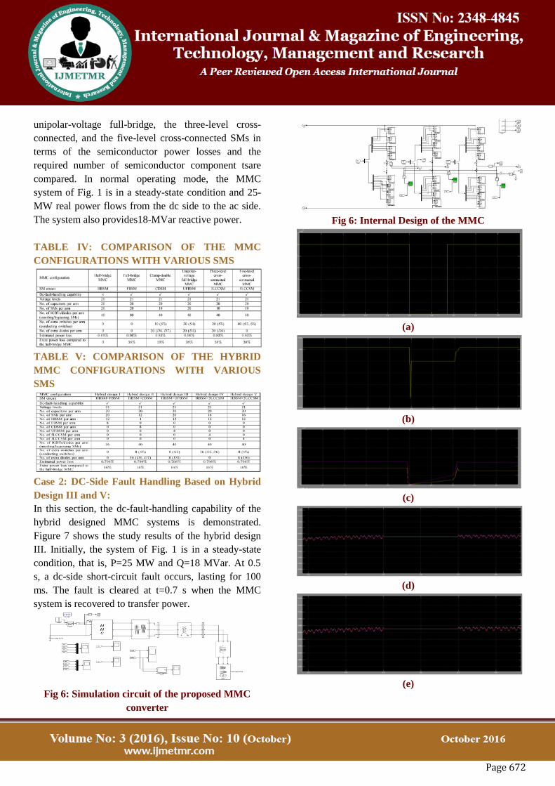
Case 2: DC-Side Fault Handling Based on Hybrid
Design III and V:
In this section, the dc-fault-handling capability of the
hybrid designed MMC systems is demonstrated.
Figure 7 shows the study results of the hybrid design
III. Initially, the system of Fig. 1 is in a steady-state
condition, that is, P=25 MW and Q=18 MVar. At 0.5
s, a dc-side short-circuit fault occurs, lasting for 100
ms. The fault is cleared at t=0.7 s when the MMC
system is recovered to transfer power.
Fig 6: Simulation circuit of the proposed MMC
converter
Fig 6: Internal Design of the MMC
(a)
(b)
(c)
(d)
(e)

Page 673
(f& g) Fig. 7. DC-side short-circuit fault handling of
the hybrid-designed MMCHVDC system (hybrid
design III) with the half-bridge and unipolar-
voltage full-bridge SMs: (a) and (b) dc voltage and
current, (c) real and reactive power, (d) and (e) SM
capacitor voltages of the upper and lower arms of
phase- , (f), and (g) ac-side currents and voltages.
(a)
(b)
(c)
(d)
(e)
(f& g) Fig. 8: DC-side short-circuit fault handling
of the hybrid-designed MMCHVDCsystem (hybrid
design V) with the half-bridge and three-level cross-
connectedSMs: (a) and (b) dc voltage and current,
(c) real and reactive power, (d) and (e) SM
capacitor voltages of the upper and lower arms of
phase- , (f), and (g) ac-side currents and voltages.
THE PROPOSED METHOD FOR MMC-HVDC
SYSTEM
A. Multiloop control strategy:
The MMC converter consists of three independent H-
bridges that are connected to a common dc-link
capacitor. VSCs are connected in series to the supply
grid through a single phase transformer. The proposed
Fault Current Interruption (FCI) consists of
independent and identical controllers for single phase
VSC of the MMC. The fundamental frequency
components of supply voltage Vs, load voltage Vl and
injected voltage Vinj.

Page 674
Fig 9: Block diagram of multi loop control strategy
υs = Vs x cos(ωt+θs) (1)
υl = Vl x cos(ωt+θl) (2)
υs =υs-υl = Vinj x cos(ωt+θinj) (3)
The FCI function requires a phasor parameter
estimator (digital filter) which attenuates the harmonic
contents of the measured signal. To attenuate all
harmonics, the filter must have a full-cycle data
window length which leads to one cycle delay in the
MMC response. Thus, a compromise between the
voltage injection speed and disturbance attenuation is
made.FCI performs satisfactorily under fault
conditions where the measured voltages and current
signals are highly distorted. Fig. 9 shows a per-phase
block diagram of the proposed MMC control system
corresponding to the FCI operation mode, where Vn is
the nominal rms phase voltage. The control system of
Fig. 9 utilizes the dc-link voltage VDC and the
harmonicfilter capacitor current icap as the input
signals.
The study in this paper is based on the fault current
detection method. The fault detection mechanism for
each phase is activated when the absolute value of the
instantaneous current exceeds twice the rated load
current. The proposed multiloop control system
includes an outer control loop (voltage phasorcontrol)
and an inner control loop (instantaneous voltage
control). The inner loop provides damping for the
transients caused by theMMC, and improves the
dynamic response and stability of the MMC. When a
downstream fault is detected, the outer loop controls
the injected voltage magnitude and phase angle of the
faulty phase(s) and reduces the load-side voltage to
zero, to interrupt the fault current and restore the PCC
voltage.
VOLTAGE PHASOR CONTROL:
In the FCI operation mode, the required injected
voltage phasor is equal to the source voltage phasor.
Performance of the voltage phasor control,in terms of
transient response, speed, and steady-state error, is
enhanced by independent control of voltage magnitude
and phase, and incorporating feed forward signals to
the feedback control system. Parameters of each
controller are determined to achieve a fast response
with zero steady-state error. The output of the phasor
control system is areference phasor denoted by
Vinj* = Vinj
*xθinj
To eliminate the effects of the dc-link voltage
variations on the injected voltages, Vinj* is normalized
by VDC.
C.INSTANTANEOUS VOLTAGE CONTROL:
Under ideal conditions, a voltage sag can be
effectively compensated if the output of the phasor-
based controller is directly fed to the sinusoidal pulse-
width modulation (SPWM)unit. However, resonances
of the harmonic filter cannot be eliminated under such
conditions. Therefore, to improve the stability and
dynamic response of the MMC, an instantaneous
injected voltage controller and a harmonic filter
capacitor current controllerare used to attenuate
resonances. The generated reference signal for the
injected voltage Vinj* is compared with the measured
injected voltage Vinj. and the error is fed to the voltage
controller. the output of the voltage controllericap* is
the reference signal for the filter capacitor current
control loop. The steady-state error of the proposed
control system is fully eliminated by the PI controllers
in the outer control loop(i.e C1 and C2) which track dc
signals (magnitude and phase angle).Therefore, there
is no need for higher order controllers in the inner
control loop which are designed based on sinusoidal
references. A large results in amplification of the
MMC. Filter resonance and can adversely impact the
system stability [18].
Thus, the transient response of the MMC is enhanced
by a feed forward loop, and a small proportional gain

Page 675
is utilized as the voltage controller. A large damps the
harmonic filter resonance more effectively, but it is
limited by practical considerations (e.g.,
amplification of capacitor current noise, measurement
noise, and dc offset [18]). Therefore, the lowest value
of the proportional gain which can effectively damp
the resonances is utilized. The output of the current
controller is added to the feed forward voltage to
derive the signal for the PWM generator. The proposed
FCI method limits the maximum fault current to about
2.5 times the nominal value of the load current and
interrupts the fault currents in less than 2 cycles.
Depicts variations of the dc-link voltage during the
FCI operation, and indicates that the dc-link voltage
rise under the worst c ase (i.e., a severe three phase
fault).
MATLAB/SIMULINK
FIG 10: SIMULINK MODEL OF THE
PROPOSED SYSTEM
FIG 11: SIMULINK MODEL OF MULTILOOP
CONTROL
FIG 12:SIMULATION RESULTS UNDER
UNBALANCED GRID CONDITIONS:A) GRID
CURRENT B) GRID VOLTAGE C)ACTIVE
POWER D) REACTIVE POWER
E)REFERENCE VOLTAGE F)DC LINK
CURRENT G)DC LINK VOLTAGE
FIG 13: SIMULATED OUTPUTS OF DC
VOLTAGE AND DC CURRENT
CONCLUSION:
This paper proposes the MPC method with a reduced
number of considered states for the MMC-HVDC
system. To control the MMC, three cost functions
were adopted: first, a cost function to control ac-side
current; second, a cost function to control the inner
unbalanced current and DC-link current; and third, a
cost function for SM capacitor voltage balancing and
switch frequency reduction. The proposed MPC
method minimizes the number of statuses to be
considered by means of the cost functions with the
MMC stably controlled. The study results demonstrate
that the hybrid-designed MMC configurations based
on a combination of the half-bridge and the proposed
SM circuits are the optimal design among all evaluated
systems in terms of dc fault-handling capability,
semiconductor power losses, and semiconductor
device requirements.

Page 676
FUTURE SCOPE:
The Alternate Arm Modular Multilevel Converter is
further implemented over Modular multilevel
converter topology for VSC based HVDC applications.
The major concern of sequential proper switching
of capacitors of each sub module can be solved by
sorting technique.
REFERENCES:
[1] S. Debnath, J. Qin, B. Bahrani, M. Saeedifard, and
P. Barbosa, “Operation,control, and applications of the
modular multilevel converter: Areview,” IEEE Trans.
Power Electron., vol. 30, no. 1, pp. 37–53, Jan.2015.
[2] S. Allebrod, R. Hamerski, and R. Marquardt, “New
transformerless,scalable modular multilevel converters
for HVDC-transmission,”inProc. IEEE Power
Electronics Specialists Conf., Jun. 2008, pp.174–179.
[3] J. Dorn, H. Huang, and D. Retzmann, “A new
multilevel voltagesourcedconverter topology for
HVDC applications,” presented at theCIGRE Session,
Paris, France, 2008, B4-30.
[4] R. Marquardt, “Modular multilevel converter: An
universal conceptfor HVDC-networks and extended
DC-bus-applications,” in Proc. Int.Power Electron.
Conf., Jun. 2010, pp. 502–507.
[5] B. Gemmell, J. Dorn, D. Retzmann, and D.
Soerangr, “Prospects ofmultilevel VSC technologies
for power transmission,” in Proc. IEEETransm.Distrib.
Conf. Expo., Apr. 2008, pp. 1–16.
[6] K. Friedrich, “Modern HVDC PLUS application of
VSC in modularmultilevel converter topology,” in
Proc. IEEE Int. Symp. Ind. Electron.,2010, pp. 3807–
3810.
[7] M. Saeedifard and R. Iravani, “Dynamic
performance of a modularmultilevel back-to-back
HVDC system,” IEEE Trans. Power Del., vol.25, no.
4, pp. 2903–2912, Oct. 2010.
[8] J. Peralta, H. Saad, S. Dennetiere, J. Mahseredjian,
and S. Nguefeu,“Detailed and averaged models for a
401-level MMC-HVDC system,”IEEE Trans. Power
Del., vol. 27, no. 3, pp. 1501–1508, Jul. 2012.
[9] J. Qin and M. Saeedifard, “Predictive control of a
modular multilevelconverter for a back-to-back HVDC
system,” IEEE Trans. Power Del.,vol. 27, no. 3, pp.
1538–1547, Jul. 2012.
[10] G. T. Son, H.-J.Lee, T. S. Nam, Y.-H.Chug, and
U.-H. Lee, “Designand control of a modular multilevel
HVDC converter with redundantpower modules for
noninterruptible energy transfer,” IEEE Trans.Power
Del., vol. 27, no. 3, pp. 1611–1619, Jul. 2012.
[11] A. Nami, J. Liang, F. Dijkhuizen, and G.
Demetriades, “Modular multilevelconverters for
HVDC applications: Review on converter cellsand
functionalities,” IEEE Trans. Power Electron., vol. 30,
no. 1, pp.18–36, Jan. 2015.
[12] L. Tang and B.-T.Ooi, “Locating and isolating dc
faults in multiterminaldc systems,” IEEE Trans. Power
Del., vol. 22, no. 3, pp.1877–1884, Jul. 2007.


![Modular Multilevel Submodules for Converters, from the ... · Modern HVDC Transmission – MMC [M²C] = Modular concept based on power electronic building blocks modular converter](https://img.dokumen.tips/doc/110x75/5ea641f2a0779206f824b607/modular-multilevel-submodules-for-converters-from-the-modern-hvdc-transmission.jpg)


![Aalborg Universitet Impact of lifetime model selections on ... · Modular Multilevel Converters (MMCs) are promising high-power Voltage-Source Converters (VSCs) for wind farms [1]](https://img.dokumen.tips/doc/110x75/5f44c47f1439a6770968c9c7/aalborg-universitet-impact-of-lifetime-model-selections-on-modular-multilevel.jpg)