Embed Size (px)
Citation preview
Analog Rytm MKIIA different drum
User Manual
FCC compliance statementThis device complies with part 15 of the FCC rules. Operation is subject to the following two conditions: (1) This device may not cause harmful interference, and (2) this device must accept any interference received, including interference that may cause undesired operation.
NOTE: This equipment has been tested and found to comply with the limits for a Class B digital device, pursuant to Part 15 of the FCC Rules. These limits are designed to provide reasonable protection against harmful interference in a residential installation. This equipment generates, uses and can radiate radio frequency energy and, if not installed and used in accordance with the instructions, may cause harmful interference to radio communications. However, there is no guarantee that interference will not occur in a particular installation. If this equipment does cause harmful interference to radio or television reception, which can be determined by turning the equipment off and on, the user is encour-aged to try to correct the interference by one or more of the following measures:
• Reorient or relocate the receiving antenna.• Increase the separation between the equipment and receiver.• Connect the equipment into an outlet on a circuit different from that to which the receiver is
connected.• Consult the dealer or an experienced radio/TV technician for help.
European Union regulation compliance statementThis product has been tested to comply with the Low Voltage Directive 2014/35/EU and the Electro-magnetic Compatibility Directive 2014/30/EU. The product meets the requirements of RoHS 2 Directive 2011/65/EU.
This symbol indicates that your product must be disposed of properly according to local laws and regulations.
Legal disclaimerThe information in this document is subject to change without notice and should not be construed as a commitment by Elektron. Elektron assumes no responsibility for any errors that may appear in this doc-ument. Elektron may also make improvements and/or changes in the products and programs described in this document at any time without notice. In no event shall Elektron be liable for any special, indirect, or consequential damages or any damages whatsoever resulting from loss of use, data, or profits, whether in an action of contract, negligence, or other action, arising out of or in connection with the use or performance of this information.
CanadaThis This Class B digital apparatus complies with Canadian ICES-003. Cet appareil numerique de la classe B est conforme a la norme NMB-003

IMPORTANT SAFETY AND MAINTENANCE INSTRUCTIONSPlease read these instructions carefully and adhere to the operating advice.
1. Do not use this unit near water.2. Never use aggressive cleaners on the casing or on the screen. Remove dust, dirt and fingerprints with
a soft, dry and non-abrasive cloth. More persistent dirt can be removed with a slightly damp cloth using only water. Disconnect all cables while doing this. Only reconnect them when the product is safely dry.
3. To avoid scratches or damage, never use sharp objects near the casing or the screen. Avoid applying any pressure to the screen itself.
4. Install in accordance with the manufacturer’s instructions. Make sure you place the unit on a stable sur-face before use. If you mount the unit in a rack, be sure to tighten all four screws in the rack mount holes.
5. Connect the unit to an easily accessible electrical outlet close to the unit.6. When transporting the unit, use accessories recommended by the manufacturer or the original box and
padding.7. Do not install near any heat sources such as radiators, heat registers, stoves, or any other equipment
(including amplifiers) producing heat. 8. Do not put a protective cover on the unit while the unit is powered on.9. This product, by itself or in combination with amplifiers, headphones or speakers, is capable of produc-
ing sound levels that may cause permanent hearing loss. Do not operate at a high volume level or at a level that is uncomfortable.
10. Protect the power cord from being walked on or pinched particularly at plugs, convenience receptacles, and the point where they exit from the unit.
11. Use attachments/accessories specified by the manufacturer.12. Unplug this unit during lightning storms or when it is not used for long periods of time.13. Refer all servicing to qualified service technicians. Servicing is required when the unit has been
damaged in any way, liquid has been spilled or objects have fallen into the unit, the unit has been exposed to rain or moisture, does not operate normally, or has been dropped.
WARNINGTo reduce the risk of fire, electrical shock or product damage:
• Do not expose the unit to rain, moisture, dripping or splashing and also avoid placing objects filled with liquid, such as vases, on the unit.
• Do not expose the unit to direct sunlight, nor use it in ambient temperatures exceeding 30°C as this can lead to malfunction.
• Do not open the casing. There are no user repairable or adjustable parts inside. Leave service and re-pairs to trained service technicians only.
• Do not exceed the limitations specified in the Electrical specifications.
SOUND PEAKS• A brief 3 kHz signal will be sent to all outs of the Analog Rytm MKII when the Test mode on the Early
Startup menu is activated. Remember to turn down the volume on all speakers and headphones before activating Test mode.
• During calibration there will be loud and unpleasant sounds on the individual outs. Disconnect these during calibration.
SAFETY INSTRUCTIONS FOR THE POWER ADAPTER ELEKTRON PSU-3b• The adapter is not safety grounded and may only be used indoors.• To ensure good ventilation for the adapter, do not place it in tight spaces. To prevent risk of electric
shock and fire because of overheating, ensure that curtains and other objects do not prevent adapter ventilation.
• Do not expose the power adapter to direct sunlight, nor use it in ambient temperatures exceeding 40°C.• Connect the adapter to an easily accessible electrical outlet close to the unit.• The adapter is in standby mode when the power cord is connected. The primary circuit is always active
when the cord is connected to the power outlet. Pull out the cord to completely disconnect the adapter.• In the EU, only use CE approved power cords.
TABLE OF CONTENTS
4
TABLE OF CONTENTS
1. INTRODUCTION . . . . . . . . . . . . . . . . . . . . . . . . . . . . . . . . . . . . . . . . . . . . . . . . . . . . . . . . . . . . . . . .81.1 CONVENTIONS IN THIS MANUAL . . . . . . . . . . . . . . . . . . . . . . . . . . . . . . . . . . . . . . . . . . . . . . . . . . . . . . . . . . . . . 8
2. THE ANALOG RYTM MKII . . . . . . . . . . . . . . . . . . . . . . . . . . . . . . . . . . . . . . . . . . . . . . . . . . . . . . .9
3. PANEL LAYOUT AND CONNECTORS . . . . . . . . . . . . . . . . . . . . . . . . . . . . . . . . . . . . . . . . . . .103.1 FRONT PANEL . . . . . . . . . . . . . . . . . . . . . . . . . . . . . . . . . . . . . . . . . . . . . . . . . . . . . . . . . . . . . . . . . . . . . . . . . . . . . 10
3.2 REAR CONNECTORS. . . . . . . . . . . . . . . . . . . . . . . . . . . . . . . . . . . . . . . . . . . . . . . . . . . . . . . . . . . . . . . . . . . . . . . 12
3.3 SETTING UP AND STARTING THE ANALOG RYTM MKII . . . . . . . . . . . . . . . . . . . . . . . . . . . . . . . . . . . . . 12
4. ANALOG RYTM MKII SOUND ARCHITECTURE. . . . . . . . . . . . . . . . . . . . . . . . . . . . . . . . . . 134.1 VOICE CIRCUITS . . . . . . . . . . . . . . . . . . . . . . . . . . . . . . . . . . . . . . . . . . . . . . . . . . . . . . . . . . . . . . . . . . . . . . . . . . . 13
4.2 ABOUT MACHINES. . . . . . . . . . . . . . . . . . . . . . . . . . . . . . . . . . . . . . . . . . . . . . . . . . . . . . . . . . . . . . . . . . . . . . . . . 13
5. OVERVIEW OF THE ANALOG RYTM MKII DATA STRUCTURE . . . . . . . . . . . . . . . . . . .145.1 +DRIVE . . . . . . . . . . . . . . . . . . . . . . . . . . . . . . . . . . . . . . . . . . . . . . . . . . . . . . . . . . . . . . . . . . . . . . . . . . . . . . . . . . . . 14
5.2 DATA STRUCTURE . . . . . . . . . . . . . . . . . . . . . . . . . . . . . . . . . . . . . . . . . . . . . . . . . . . . . . . . . . . . . . . . . . . . . . . . . 145.2.1 PROJECT . . . . . . . . . . . . . . . . . . . . . . . . . . . . . . . . . . . . . . . . . . . . . . . . . . . . . . . . . . . . . . . . . . . . . . . . . . . . . . . . . 145.2.2 KITS . . . . . . . . . . . . . . . . . . . . . . . . . . . . . . . . . . . . . . . . . . . . . . . . . . . . . . . . . . . . . . . . . . . . . . . . . . . . . . . . . . . . . 145.2.3 SOUNDS . . . . . . . . . . . . . . . . . . . . . . . . . . . . . . . . . . . . . . . . . . . . . . . . . . . . . . . . . . . . . . . . . . . . . . . . . . . . . . . . . 145.2.4 SAMPLES . . . . . . . . . . . . . . . . . . . . . . . . . . . . . . . . . . . . . . . . . . . . . . . . . . . . . . . . . . . . . . . . . . . . . . . . . . . . . . . . 145.2.5 PATTERNS . . . . . . . . . . . . . . . . . . . . . . . . . . . . . . . . . . . . . . . . . . . . . . . . . . . . . . . . . . . . . . . . . . . . . . . . . . . . . . . 145.2.6 SONGS . . . . . . . . . . . . . . . . . . . . . . . . . . . . . . . . . . . . . . . . . . . . . . . . . . . . . . . . . . . . . . . . . . . . . . . . . . . . . . . . . . 155.2.7 GLOBALS . . . . . . . . . . . . . . . . . . . . . . . . . . . . . . . . . . . . . . . . . . . . . . . . . . . . . . . . . . . . . . . . . . . . . . . . . . . . . . . . 15
5.3 ABOUT THE TRACKS . . . . . . . . . . . . . . . . . . . . . . . . . . . . . . . . . . . . . . . . . . . . . . . . . . . . . . . . . . . . . . . . . . . . . . 155.3.1 THE DRUM TRACKS . . . . . . . . . . . . . . . . . . . . . . . . . . . . . . . . . . . . . . . . . . . . . . . . . . . . . . . . . . . . . . . . . . . . . . . 155.3.2 THE FX TRACK . . . . . . . . . . . . . . . . . . . . . . . . . . . . . . . . . . . . . . . . . . . . . . . . . . . . . . . . . . . . . . . . . . . . . . . . . . . 155.3.3 EDITING THE TRACKS . . . . . . . . . . . . . . . . . . . . . . . . . . . . . . . . . . . . . . . . . . . . . . . . . . . . . . . . . . . . . . . . . . . . 15
6. THE USER INTERFACE . . . . . . . . . . . . . . . . . . . . . . . . . . . . . . . . . . . . . . . . . . . . . . . . . . . . . . . .166.1 SCREEN NAVIGATION . . . . . . . . . . . . . . . . . . . . . . . . . . . . . . . . . . . . . . . . . . . . . . . . . . . . . . . . . . . . . . . . . . . . . . 16
6.2 PARAMETER EDITING . . . . . . . . . . . . . . . . . . . . . . . . . . . . . . . . . . . . . . . . . . . . . . . . . . . . . . . . . . . . . . . . . . . . . 166.2.1 QUICK PARAMETER EDITING . . . . . . . . . . . . . . . . . . . . . . . . . . . . . . . . . . . . . . . . . . . . . . . . . . . . . . . . . . . . . 166.2.2 PARAMETER VALUE JUMP . . . . . . . . . . . . . . . . . . . . . . . . . . . . . . . . . . . . . . . . . . . . . . . . . . . . . . . . . . . . . . . . 166.2.3 [FUNC] KEY PRESS COMBINATIONS . . . . . . . . . . . . . . . . . . . . . . . . . . . . . . . . . . . . . . . . . . . . . . . . . . . . . 16
6.3 QUICK SCROLLING . . . . . . . . . . . . . . . . . . . . . . . . . . . . . . . . . . . . . . . . . . . . . . . . . . . . . . . . . . . . . . . . . . . . . . . . 17
6.4 COPY, CLEAR AND PASTE . . . . . . . . . . . . . . . . . . . . . . . . . . . . . . . . . . . . . . . . . . . . . . . . . . . . . . . . . . . . . . . . . 17
6.5 THE NAMING SCREEN . . . . . . . . . . . . . . . . . . . . . . . . . . . . . . . . . . . . . . . . . . . . . . . . . . . . . . . . . . . . . . . . . . . . . 176.5.1 POP-UP NAMING . . . . . . . . . . . . . . . . . . . . . . . . . . . . . . . . . . . . . . . . . . . . . . . . . . . . . . . . . . . . . . . . . . . . . . . . . . 17
6.6 OVERBRIDGE . . . . . . . . . . . . . . . . . . . . . . . . . . . . . . . . . . . . . . . . . . . . . . . . . . . . . . . . . . . . . . . . . . . . . . . . . . . . . . 18
7. QUICK START . . . . . . . . . . . . . . . . . . . . . . . . . . . . . . . . . . . . . . . . . . . . . . . . . . . . . . . . . . . . . . . . .197.1 PLAYING THE FACTORY PRESETS . . . . . . . . . . . . . . . . . . . . . . . . . . . . . . . . . . . . . . . . . . . . . . . . . . . . . . . . . . 19
7.1.1 PERFORMANCE MODE . . . . . . . . . . . . . . . . . . . . . . . . . . . . . . . . . . . . . . . . . . . . . . . . . . . . . . . . . . . . . . . . . . . . 197.1.2 SCENE MODE . . . . . . . . . . . . . . . . . . . . . . . . . . . . . . . . . . . . . . . . . . . . . . . . . . . . . . . . . . . . . . . . . . . . . . . . . . . . . 197.1.3 CHROMATIC MODE . . . . . . . . . . . . . . . . . . . . . . . . . . . . . . . . . . . . . . . . . . . . . . . . . . . . . . . . . . . . . . . . . . . . . . . 197.1.4 MUTE MODE . . . . . . . . . . . . . . . . . . . . . . . . . . . . . . . . . . . . . . . . . . . . . . . . . . . . . . . . . . . . . . . . . . . . . . . . . . . . . . 197.1.5 TEMPO . . . . . . . . . . . . . . . . . . . . . . . . . . . . . . . . . . . . . . . . . . . . . . . . . . . . . . . . . . . . . . . . . . . . . . . . . . . . . . . . . . .207.1.6 EDITING PARAMETERS . . . . . . . . . . . . . . . . . . . . . . . . . . . . . . . . . . . . . . . . . . . . . . . . . . . . . . . . . . . . . . . . . . . .20
8. ANALOG RYTM MKII CONTROLS . . . . . . . . . . . . . . . . . . . . . . . . . . . . . . . . . . . . . . . . . . . . . . 218.1 PADS . . . . . . . . . . . . . . . . . . . . . . . . . . . . . . . . . . . . . . . . . . . . . . . . . . . . . . . . . . . . . . . . . . . . . . . . . . . . . . . . . . . . . . 21
8.2 MACHINES . . . . . . . . . . . . . . . . . . . . . . . . . . . . . . . . . . . . . . . . . . . . . . . . . . . . . . . . . . . . . . . . . . . . . . . . . . . . . . . . 22
TABLE OF CONTENTS
5
8.3 ROTARY ENCODERS . . . . . . . . . . . . . . . . . . . . . . . . . . . . . . . . . . . . . . . . . . . . . . . . . . . . . . . . . . . . . . . . . . . . . . . 22
8.4 PRAGMATIC OPERATION . . . . . . . . . . . . . . . . . . . . . . . . . . . . . . . . . . . . . . . . . . . . . . . . . . . . . . . . . . . . . . . . . . 22
8.5 KEY BEHAVIOR . . . . . . . . . . . . . . . . . . . . . . . . . . . . . . . . . . . . . . . . . . . . . . . . . . . . . . . . . . . . . . . . . . . . . . . . . . . . 22
8.6 MIDI NOTES . . . . . . . . . . . . . . . . . . . . . . . . . . . . . . . . . . . . . . . . . . . . . . . . . . . . . . . . . . . . . . . . . . . . . . . . . . . . . . . 22
8.7 MODE KEYS . . . . . . . . . . . . . . . . . . . . . . . . . . . . . . . . . . . . . . . . . . . . . . . . . . . . . . . . . . . . . . . . . . . . . . . . . . . . . . . 238.7.1 PLAY MODE . . . . . . . . . . . . . . . . . . . . . . . . . . . . . . . . . . . . . . . . . . . . . . . . . . . . . . . . . . . . . . . . . . . . . . . . . . . . . . . 238.7.2 MUTE MODE . . . . . . . . . . . . . . . . . . . . . . . . . . . . . . . . . . . . . . . . . . . . . . . . . . . . . . . . . . . . . . . . . . . . . . . . . . . . . 238.7.3 CHROMATIC MODE . . . . . . . . . . . . . . . . . . . . . . . . . . . . . . . . . . . . . . . . . . . . . . . . . . . . . . . . . . . . . . . . . . . . . . 238.7.4 SCENE MODE . . . . . . . . . . . . . . . . . . . . . . . . . . . . . . . . . . . . . . . . . . . . . . . . . . . . . . . . . . . . . . . . . . . . . . . . . . . . 238.7.5 PERFORMANCE MODE . . . . . . . . . . . . . . . . . . . . . . . . . . . . . . . . . . . . . . . . . . . . . . . . . . . . . . . . . . . . . . . . . . . 23
9. PROJECTS . . . . . . . . . . . . . . . . . . . . . . . . . . . . . . . . . . . . . . . . . . . . . . . . . . . . . . . . . . . . . . . . . . . 249.1 PROJECT MENU . . . . . . . . . . . . . . . . . . . . . . . . . . . . . . . . . . . . . . . . . . . . . . . . . . . . . . . . . . . . . . . . . . . . . . . . . . . . 24
10. KITS AND SOUNDS . . . . . . . . . . . . . . . . . . . . . . . . . . . . . . . . . . . . . . . . . . . . . . . . . . . . . . . . . . 2610.1 THE +DRIVE SOUND LIBRARY AND THE SOUND POOL . . . . . . . . . . . . . . . . . . . . . . . . . . . . . . . . . . . . . 26
10.2 KIT MENU . . . . . . . . . . . . . . . . . . . . . . . . . . . . . . . . . . . . . . . . . . . . . . . . . . . . . . . . . . . . . . . . . . . . . . . . . . . . . . . . 2610.2.1 RELOAD KIT . . . . . . . . . . . . . . . . . . . . . . . . . . . . . . . . . . . . . . . . . . . . . . . . . . . . . . . . . . . . . . . . . . . . . . . . . . . . . 2610.2.2 LOAD KIT . . . . . . . . . . . . . . . . . . . . . . . . . . . . . . . . . . . . . . . . . . . . . . . . . . . . . . . . . . . . . . . . . . . . . . . . . . . . . . . . 2610.2.3 SAVE KIT . . . . . . . . . . . . . . . . . . . . . . . . . . . . . . . . . . . . . . . . . . . . . . . . . . . . . . . . . . . . . . . . . . . . . . . . . . . . . . . . 2710.2.4 CLEAR KIT . . . . . . . . . . . . . . . . . . . . . . . . . . . . . . . . . . . . . . . . . . . . . . . . . . . . . . . . . . . . . . . . . . . . . . . . . . . . . . 2710.2.5 TRACK ROUTING KIT . . . . . . . . . . . . . . . . . . . . . . . . . . . . . . . . . . . . . . . . . . . . . . . . . . . . . . . . . . . . . . . . . . . . 2710.2.6 CONTROL IN 1 MOD . . . . . . . . . . . . . . . . . . . . . . . . . . . . . . . . . . . . . . . . . . . . . . . . . . . . . . . . . . . . . . . . . . . . . 2710.2.7 CONTROL IN 2 MOD . . . . . . . . . . . . . . . . . . . . . . . . . . . . . . . . . . . . . . . . . . . . . . . . . . . . . . . . . . . . . . . . . . . . . 28
10.3 SCENE MODE . . . . . . . . . . . . . . . . . . . . . . . . . . . . . . . . . . . . . . . . . . . . . . . . . . . . . . . . . . . . . . . . . . . . . . . . . . . . . 2810.3.1 SCENE EDIT . . . . . . . . . . . . . . . . . . . . . . . . . . . . . . . . . . . . . . . . . . . . . . . . . . . . . . . . . . . . . . . . . . . . . . . . . . . . . 28
10.4 PERFORMANCE MODE . . . . . . . . . . . . . . . . . . . . . . . . . . . . . . . . . . . . . . . . . . . . . . . . . . . . . . . . . . . . . . . . . . . 2910.4.1 PERFORMANCE EDIT . . . . . . . . . . . . . . . . . . . . . . . . . . . . . . . . . . . . . . . . . . . . . . . . . . . . . . . . . . . . . . . . . . . . 2910.4.2 QUICK PERFORMANCE . . . . . . . . . . . . . . . . . . . . . . . . . . . . . . . . . . . . . . . . . . . . . . . . . . . . . . . . . . . . . . . . . .30
10.5 SOUND MENU . . . . . . . . . . . . . . . . . . . . . . . . . . . . . . . . . . . . . . . . . . . . . . . . . . . . . . . . . . . . . . . . . . . . . . . . . . . . 3110.5.1 SOUND BROWSER . . . . . . . . . . . . . . . . . . . . . . . . . . . . . . . . . . . . . . . . . . . . . . . . . . . . . . . . . . . . . . . . . . . . . . . 3110.5.2 SOUND MANAGER . . . . . . . . . . . . . . . . . . . . . . . . . . . . . . . . . . . . . . . . . . . . . . . . . . . . . . . . . . . . . . . . . . . . . . 3210.5.3 CLEAR TRACK SOUND . . . . . . . . . . . . . . . . . . . . . . . . . . . . . . . . . . . . . . . . . . . . . . . . . . . . . . . . . . . . . . . . . .3310.5.4 RENAME TRACK SOUND . . . . . . . . . . . . . . . . . . . . . . . . . . . . . . . . . . . . . . . . . . . . . . . . . . . . . . . . . . . . . . . .3310.5.5 SOUND SETTINGS . . . . . . . . . . . . . . . . . . . . . . . . . . . . . . . . . . . . . . . . . . . . . . . . . . . . . . . . . . . . . . . . . . . . . .33
10.6 PLAYING A SOUND . . . . . . . . . . . . . . . . . . . . . . . . . . . . . . . . . . . . . . . . . . . . . . . . . . . . . . . . . . . . . . . . . . . . . . . 34
10.7 EDITING A SOUND . . . . . . . . . . . . . . . . . . . . . . . . . . . . . . . . . . . . . . . . . . . . . . . . . . . . . . . . . . . . . . . . . . . . . . . . 34
10.8 SELECTING A SAMPLE . . . . . . . . . . . . . . . . . . . . . . . . . . . . . . . . . . . . . . . . . . . . . . . . . . . . . . . . . . . . . . . . . . . . 35
10.9 EDITING THE FX . . . . . . . . . . . . . . . . . . . . . . . . . . . . . . . . . . . . . . . . . . . . . . . . . . . . . . . . . . . . . . . . . . . . . . . . . . 36
11. THE SEQUENCER . . . . . . . . . . . . . . . . . . . . . . . . . . . . . . . . . . . . . . . . . . . . . . . . . . . . . . . . . . . . 3711.1 BASIC PATTERN OPERATIONS . . . . . . . . . . . . . . . . . . . . . . . . . . . . . . . . . . . . . . . . . . . . . . . . . . . . . . . . . . . . . 37
11.1.1 SELECTING A PATTERN . . . . . . . . . . . . . . . . . . . . . . . . . . . . . . . . . . . . . . . . . . . . . . . . . . . . . . . . . . . . . . . . . . . 3711.1.2 PATTERN CONTROL . . . . . . . . . . . . . . . . . . . . . . . . . . . . . . . . . . . . . . . . . . . . . . . . . . . . . . . . . . . . . . . . . . . . . . 3711.1.3 TEMPO . . . . . . . . . . . . . . . . . . . . . . . . . . . . . . . . . . . . . . . . . . . . . . . . . . . . . . . . . . . . . . . . . . . . . . . . . . . . . . . . . . . 37
11.2 PATTERN MODES . . . . . . . . . . . . . . . . . . . . . . . . . . . . . . . . . . . . . . . . . . . . . . . . . . . . . . . . . . . . . . . . . . . . . . . . . 38
11.3 EDITING A PATTERN . . . . . . . . . . . . . . . . . . . . . . . . . . . . . . . . . . . . . . . . . . . . . . . . . . . . . . . . . . . . . . . . . . . . . . 3811.3.1 TRIG TYPES . . . . . . . . . . . . . . . . . . . . . . . . . . . . . . . . . . . . . . . . . . . . . . . . . . . . . . . . . . . . . . . . . . . . . . . . . . . . . .3811.3.2 GRID RECORDING MODE . . . . . . . . . . . . . . . . . . . . . . . . . . . . . . . . . . . . . . . . . . . . . . . . . . . . . . . . . . . . . . . .3911.3.3 LIVE RECORDING MODE . . . . . . . . . . . . . . . . . . . . . . . . . . . . . . . . . . . . . . . . . . . . . . . . . . . . . . . . . . . . . . . . .39
11.4 RETRIG MENU. . . . . . . . . . . . . . . . . . . . . . . . . . . . . . . . . . . . . . . . . . . . . . . . . . . . . . . . . . . . . . . . . . . . . . . . . . . . . 39
11.5 TRACK MENU . . . . . . . . . . . . . . . . . . . . . . . . . . . . . . . . . . . . . . . . . . . . . . . . . . . . . . . . . . . . . . . . . . . . . . . . . . . . . 40
11.6 PATTERN MENU . . . . . . . . . . . . . . . . . . . . . . . . . . . . . . . . . . . . . . . . . . . . . . . . . . . . . . . . . . . . . . . . . . . . . . . . . . . 41

TABLE OF CONTENTS
6
11.7 TRIG MENU . . . . . . . . . . . . . . . . . . . . . . . . . . . . . . . . . . . . . . . . . . . . . . . . . . . . . . . . . . . . . . . . . . . . . . . . . . . . . . . 4111.7.1 QUANTIZATION . . . . . . . . . . . . . . . . . . . . . . . . . . . . . . . . . . . . . . . . . . . . . . . . . . . . . . . . . . . . . . . . . . . . . . . . . . . 42
11.8 FIXED VELOCITY . . . . . . . . . . . . . . . . . . . . . . . . . . . . . . . . . . . . . . . . . . . . . . . . . . . . . . . . . . . . . . . . . . . . . . . . . . 42
11.9 CLICK TRACK . . . . . . . . . . . . . . . . . . . . . . . . . . . . . . . . . . . . . . . . . . . . . . . . . . . . . . . . . . . . . . . . . . . . . . . . . . . . . 43
11.10 SCALE MENU . . . . . . . . . . . . . . . . . . . . . . . . . . . . . . . . . . . . . . . . . . . . . . . . . . . . . . . . . . . . . . . . . . . . . . . . . . . . . 4311.10.1 NORMAL MODE . . . . . . . . . . . . . . . . . . . . . . . . . . . . . . . . . . . . . . . . . . . . . . . . . . . . . . . . . . . . . . . . . . . . . . . . .4311.10.2 ADVANCED MODE . . . . . . . . . . . . . . . . . . . . . . . . . . . . . . . . . . . . . . . . . . . . . . . . . . . . . . . . . . . . . . . . . . . . . .44
11.11 SEQUENCER FEATURES . . . . . . . . . . . . . . . . . . . . . . . . . . . . . . . . . . . . . . . . . . . . . . . . . . . . . . . . . . . . . . . . . . 4411.11.1 PARAMETER LOCKS . . . . . . . . . . . . . . . . . . . . . . . . . . . . . . . . . . . . . . . . . . . . . . . . . . . . . . . . . . . . . . . . . . . . .4411.11.2 SOUND LOCKS . . . . . . . . . . . . . . . . . . . . . . . . . . . . . . . . . . . . . . . . . . . . . . . . . . . . . . . . . . . . . . . . . . . . . . . . . . 4511.11.3 CONDITIONAL LOCKS . . . . . . . . . . . . . . . . . . . . . . . . . . . . . . . . . . . . . . . . . . . . . . . . . . . . . . . . . . . . . . . . . . . 4511.11.4 FILL MODE . . . . . . . . . . . . . . . . . . . . . . . . . . . . . . . . . . . . . . . . . . . . . . . . . . . . . . . . . . . . . . . . . . . . . . . . . . . . . .4611.11.5 TRIG MUTE . . . . . . . . . . . . . . . . . . . . . . . . . . . . . . . . . . . . . . . . . . . . . . . . . . . . . . . . . . . . . . . . . . . . . . . . . . . . . .4611.11.6 ACCENT . . . . . . . . . . . . . . . . . . . . . . . . . . . . . . . . . . . . . . . . . . . . . . . . . . . . . . . . . . . . . . . . . . . . . . . . . . . . . . . . .4611.11.7 SWING . . . . . . . . . . . . . . . . . . . . . . . . . . . . . . . . . . . . . . . . . . . . . . . . . . . . . . . . . . . . . . . . . . . . . . . . . . . . . . . . . . . 4711.11.8 PARAMETER SLIDE . . . . . . . . . . . . . . . . . . . . . . . . . . . . . . . . . . . . . . . . . . . . . . . . . . . . . . . . . . . . . . . . . . . . . . 4711.11.9 COPY, PASTE, AND CLEAR OPERATIONS . . . . . . . . . . . . . . . . . . . . . . . . . . . . . . . . . . . . . . . . . . . . . . . . .4811.11.10 QUICK SAVE AND RELOAD COMMANDS . . . . . . . . . . . . . . . . . . . . . . . . . . . . . . . . . . . . . . . . . . . . . . . .48
12. CHAINS AND SONGS . . . . . . . . . . . . . . . . . . . . . . . . . . . . . . . . . . . . . . . . . . . . . . . . . . . . . . . . 4912.1 CHAINS . . . . . . . . . . . . . . . . . . . . . . . . . . . . . . . . . . . . . . . . . . . . . . . . . . . . . . . . . . . . . . . . . . . . . . . . . . . . . . . . . . . 49
12.1.1 DETAILED MODE . . . . . . . . . . . . . . . . . . . . . . . . . . . . . . . . . . . . . . . . . . . . . . . . . . . . . . . . . . . . . . . . . . . . . . . . .4912.1.2 QUICK MODE . . . . . . . . . . . . . . . . . . . . . . . . . . . . . . . . . . . . . . . . . . . . . . . . . . . . . . . . . . . . . . . . . . . . . . . . . . . .49
12.2 SONGS . . . . . . . . . . . . . . . . . . . . . . . . . . . . . . . . . . . . . . . . . . . . . . . . . . . . . . . . . . . . . . . . . . . . . . . . . . . . . . . . . . . 4912.2.1 SONG EDIT MENU . . . . . . . . . . . . . . . . . . . . . . . . . . . . . . . . . . . . . . . . . . . . . . . . . . . . . . . . . . . . . . . . . . . . . . . .4912.2.2 ADDING SONG ROWS AND ASSIGNING PATTERNS AND CHAINS . . . . . . . . . . . . . . . . . . . . . . . . .5012.2.3 ADDING REPEATS AND MUTES . . . . . . . . . . . . . . . . . . . . . . . . . . . . . . . . . . . . . . . . . . . . . . . . . . . . . . . . . .5012.2.4 SONG MENU . . . . . . . . . . . . . . . . . . . . . . . . . . . . . . . . . . . . . . . . . . . . . . . . . . . . . . . . . . . . . . . . . . . . . . . . . . . . 51
13. SAMPLING . . . . . . . . . . . . . . . . . . . . . . . . . . . . . . . . . . . . . . . . . . . . . . . . . . . . . . . . . . . . . . . . . . 5213.1 SAMPLING MENU . . . . . . . . . . . . . . . . . . . . . . . . . . . . . . . . . . . . . . . . . . . . . . . . . . . . . . . . . . . . . . . . . . . . . . . . . . 52
13.1.1 REC . . . . . . . . . . . . . . . . . . . . . . . . . . . . . . . . . . . . . . . . . . . . . . . . . . . . . . . . . . . . . . . . . . . . . . . . . . . . . . . . . . . . . . 5213.1.2 ARM . . . . . . . . . . . . . . . . . . . . . . . . . . . . . . . . . . . . . . . . . . . . . . . . . . . . . . . . . . . . . . . . . . . . . . . . . . . . . . . . . . . . . 5213.1.3 THR . . . . . . . . . . . . . . . . . . . . . . . . . . . . . . . . . . . . . . . . . . . . . . . . . . . . . . . . . . . . . . . . . . . . . . . . . . . . . . . . . . . . . . 5213.1.4 SRC . . . . . . . . . . . . . . . . . . . . . . . . . . . . . . . . . . . . . . . . . . . . . . . . . . . . . . . . . . . . . . . . . . . . . . . . . . . . . . . . . . . . . 5213.1.5 MON . . . . . . . . . . . . . . . . . . . . . . . . . . . . . . . . . . . . . . . . . . . . . . . . . . . . . . . . . . . . . . . . . . . . . . . . . . . . . . . . . . . . . 52
13.2 SAMPLING WITH THE ANALOG RYTM MKII . . . . . . . . . . . . . . . . . . . . . . . . . . . . . . . . . . . . . . . . . . . . . . . . 52
13.3 DIRECT SAMPLING . . . . . . . . . . . . . . . . . . . . . . . . . . . . . . . . . . . . . . . . . . . . . . . . . . . . . . . . . . . . . . . . . . . . . . . 53
14. GLOBAL SETTINGS MENU . . . . . . . . . . . . . . . . . . . . . . . . . . . . . . . . . . . . . . . . . . . . . . . . . . 5414.1 PROJECT . . . . . . . . . . . . . . . . . . . . . . . . . . . . . . . . . . . . . . . . . . . . . . . . . . . . . . . . . . . . . . . . . . . . . . . . . . . . . . . . . 54
14.2 SAMPLES . . . . . . . . . . . . . . . . . . . . . . . . . . . . . . . . . . . . . . . . . . . . . . . . . . . . . . . . . . . . . . . . . . . . . . . . . . . . . . . . . 5414.2.1 LOADING, UNLOADING OR REPLACING A SAMPLE . . . . . . . . . . . . . . . . . . . . . . . . . . . . . . . . . . . . . . . 5414.2.2 RECEIVING SAMPLES FROM A COMPUTER . . . . . . . . . . . . . . . . . . . . . . . . . . . . . . . . . . . . . . . . . . . . . . 5514.2.3 CREATING A NEW DESTINATION DIRECTORY . . . . . . . . . . . . . . . . . . . . . . . . . . . . . . . . . . . . . . . . . . . . 56
14.3 GLOBAL SLOT . . . . . . . . . . . . . . . . . . . . . . . . . . . . . . . . . . . . . . . . . . . . . . . . . . . . . . . . . . . . . . . . . . . . . . . . . . . . 56
14.4 SEQUENCER CONFIG . . . . . . . . . . . . . . . . . . . . . . . . . . . . . . . . . . . . . . . . . . . . . . . . . . . . . . . . . . . . . . . . . . . . . 56
14.5 MIDI CONFIG . . . . . . . . . . . . . . . . . . . . . . . . . . . . . . . . . . . . . . . . . . . . . . . . . . . . . . . . . . . . . . . . . . . . . . . . . . . . . 5714.5.1 SYNC . . . . . . . . . . . . . . . . . . . . . . . . . . . . . . . . . . . . . . . . . . . . . . . . . . . . . . . . . . . . . . . . . . . . . . . . . . . . . . . . . . . . 5714.5.2 PORT CONFIG . . . . . . . . . . . . . . . . . . . . . . . . . . . . . . . . . . . . . . . . . . . . . . . . . . . . . . . . . . . . . . . . . . . . . . . . . . . 5714.5.3 CHANNELS . . . . . . . . . . . . . . . . . . . . . . . . . . . . . . . . . . . . . . . . . . . . . . . . . . . . . . . . . . . . . . . . . . . . . . . . . . . . . . 58
14.6 TRACK ROUTING GLOBAL . . . . . . . . . . . . . . . . . . . . . . . . . . . . . . . . . . . . . . . . . . . . . . . . . . . . . . . . . . . . . . . . 59
14.7 CONTROL INPUT 1 . . . . . . . . . . . . . . . . . . . . . . . . . . . . . . . . . . . . . . . . . . . . . . . . . . . . . . . . . . . . . . . . . . . . . . . . 59
14.8 CONTROL INPUT 2 . . . . . . . . . . . . . . . . . . . . . . . . . . . . . . . . . . . . . . . . . . . . . . . . . . . . . . . . . . . . . . . . . . . . . . . . 60

TABLE OF CONTENTS
7
14.9 SYSEX DUMP . . . . . . . . . . . . . . . . . . . . . . . . . . . . . . . . . . . . . . . . . . . . . . . . . . . . . . . . . . . . . . . . . . . . . . . . . . . . . 6014.9.1 SYSEX SEND . . . . . . . . . . . . . . . . . . . . . . . . . . . . . . . . . . . . . . . . . . . . . . . . . . . . . . . . . . . . . . . . . . . . . . . . . . . . .6014.9.2 SYSEX RECEIVE . . . . . . . . . . . . . . . . . . . . . . . . . . . . . . . . . . . . . . . . . . . . . . . . . . . . . . . . . . . . . . . . . . . . . . . . . 61
14.10 SYSTEM . . . . . . . . . . . . . . . . . . . . . . . . . . . . . . . . . . . . . . . . . . . . . . . . . . . . . . . . . . . . . . . . . . . . . . . . . . . . . . . . . 6214.10.1 USB CONFIG . . . . . . . . . . . . . . . . . . . . . . . . . . . . . . . . . . . . . . . . . . . . . . . . . . . . . . . . . . . . . . . . . . . . . . . . . . . . 6214.10.2 OS UPGRADE . . . . . . . . . . . . . . . . . . . . . . . . . . . . . . . . . . . . . . . . . . . . . . . . . . . . . . . . . . . . . . . . . . . . . . . . . . . 6214.10.3 FORMAT +DRIVE . . . . . . . . . . . . . . . . . . . . . . . . . . . . . . . . . . . . . . . . . . . . . . . . . . . . . . . . . . . . . . . . . . . . . . . .6314.10.4 CALIBRATION. . . . . . . . . . . . . . . . . . . . . . . . . . . . . . . . . . . . . . . . . . . . . . . . . . . . . . . . . . . . . . . . . . . . . . . . . . .63
15. STARTUP MENU . . . . . . . . . . . . . . . . . . . . . . . . . . . . . . . . . . . . . . . . . . . . . . . . . . . . . . . . . . . . . 6415.1 TEST MODE . . . . . . . . . . . . . . . . . . . . . . . . . . . . . . . . . . . . . . . . . . . . . . . . . . . . . . . . . . . . . . . . . . . . . . . . . . . . . . . 64
15.2 EMPTY RESET . . . . . . . . . . . . . . . . . . . . . . . . . . . . . . . . . . . . . . . . . . . . . . . . . . . . . . . . . . . . . . . . . . . . . . . . . . . . 64
15.3 FACTORY RESET . . . . . . . . . . . . . . . . . . . . . . . . . . . . . . . . . . . . . . . . . . . . . . . . . . . . . . . . . . . . . . . . . . . . . . . . . 64
15.4 OS UPGRADE . . . . . . . . . . . . . . . . . . . . . . . . . . . . . . . . . . . . . . . . . . . . . . . . . . . . . . . . . . . . . . . . . . . . . . . . . . . . . 64
15.5 EXIT . . . . . . . . . . . . . . . . . . . . . . . . . . . . . . . . . . . . . . . . . . . . . . . . . . . . . . . . . . . . . . . . . . . . . . . . . . . . . . . . . . . . . . 64
16. SETUP EXAMPLES . . . . . . . . . . . . . . . . . . . . . . . . . . . . . . . . . . . . . . . . . . . . . . . . . . . . . . . . . . 6516.1 ANALOG RYTM MKII WITH A MONOPHONIC BASS MACHINE . . . . . . . . . . . . . . . . . . . . . . . . . . . . . . . 65
16.2 ANALOG RYTM MKII WITH A STEREOPHONIC DRUM MACHINE . . . . . . . . . . . . . . . . . . . . . . . . . . . . 65
16.3 ANALOG RYTM MKII WITH OTHER ELEKTRON GEAR . . . . . . . . . . . . . . . . . . . . . . . . . . . . . . . . . . . . . . 66
17. USEFUL KEY COMBINATIONS (QUICK KEYS) . . . . . . . . . . . . . . . . . . . . . . . . . . . . . . . . . 68
18. TECHNICAL INFORMATION . . . . . . . . . . . . . . . . . . . . . . . . . . . . . . . . . . . . . . . . . . . . . . . . . . 70
19. CREDITS AND CONTACT INFORMATION . . . . . . . . . . . . . . . . . . . . . . . . . . . . . . . . . . . . . 70
APPENDIX A: DRUM TRACK PARAMETERS. . . . . . . . . . . . . . . . . . . . . . . . . . . . . . . . . . . . . . . 71
APPENDIX B: FX TRACK PARAMETERS . . . . . . . . . . . . . . . . . . . . . . . . . . . . . . . . . . . . . . . . . .75
APPENDIX C: MIDI . . . . . . . . . . . . . . . . . . . . . . . . . . . . . . . . . . . . . . . . . . . . . . . . . . . . . . . . . . . . . . 79
APPENDIX D: MACHINES . . . . . . . . . . . . . . . . . . . . . . . . . . . . . . . . . . . . . . . . . . . . . . . . . . . . . . . 88

1. INTRODUCTION
8
1. INTRODUCTIONThank you for purchasing Analog Rytm MKII. It is a hybrid analog/digital drum machine featuring, among many other things, the intuitive Elektron step sequencer. The innovative combination of modern technolo-gy and tried and trusted ways of sound generation lets you create any kind of drum: purely analog, sam-ple-based or a combination of the two. To get the most out of your machine, we recommend that you read this manual in its entirety.
1.1 CONVENTIONS IN THIS MANUALIn this manual, we use the following conventions to describe the Analog Rytm MKII user interface:
• KEY NAMES Written in uppercase, bold style and within brackets. For example, the key labeled “FUNC” is called [FUNC].
• KNOBS Written in uppercase, bold, italic letters. For example, the knob “Track Level” is called TRACK LEVEL.
• LED INDICATORS Written in uppercase letters with angle brackets. For example, the pattern page LEDs are called: <PATTERN PAGE>.
• MENU NAMES Written in uppercase letters. For example, the PROJECT menu.
• PARAMETER NAMES, MENU OPTIONS Written in uppercase bold letters for parameter names and certain menu options where you can make settings or perform actions. For example, CLOCK SEND.
• PARAMETER SETTING ALTERNATIVES Written in uppercase letters. For example, OFF.
• SCREEN MESSAGES Written in uppercase letters with quotation marks. For example, “BANK A: CHOOSE PTN.”
You also find the following symbols throughout the manual:
Important information that requires your attention.
A tip that makes it easier for you to interact with the Analog Rytm MKII
2. THE ANALOG RYTM MKII
9
2. THE ANALOG RYTM MKIIRhythm, a forward motion carried by regular elements and silences, is something that is present in all our lives. You can see it in the motion of the astronomical bodies that creates the shifting of days, months and years. It is also happening inside our human bodies where biological clocks are governing our internal pro-cesses. The rhythm of life drives us inexorably forward and carries us along on our journey.
However, rhythm is not only something that controls us, but it is also something we control and create. We harness the rhythm of probability and re-occurrence to guide us to make the right decisions. We create cy-cles and patterns that help us to make order in a complex world and to establish a sense of stability in life.
Rhythm is also one of the foundational building blocks of music. The steady beat of the drums has been our constant companion throughout all human history. From the primitive beats of the ancient tribal cultures via the classical masters to the dark dance floors of the Berlin clubs - rhythm is there!
The Elektron Analog Rytm MKII truly adds its beat and power to the pulse of life. It is an eight voice analog/digital hybrid drum machine featuring the twang of the analog domain, the instant control, and effects of the digital domain and the wonderful interplay of both. The analog signal path, digital controls, samples, additive modulation and sampling capability, makes this drum machine a solid instrument with a voice of its own. The innovative combination of modern technology and tried and trusted ways of sound generation lets you create any kind of drum: purely analog, sample-based or a combination of the two. For all its layers of complexity and depth, it remains instantly accessible and - we are sure you agree - fun to play.
Whether the musical world you choose to inhabit is an ordered, harmonious and intelligible one or one of disharmony, chaos and earth-shattering noise, the Analog Rytm MKII will be your guide, companion, and rhythm-maker. It is our firm belief that you will have as much fun using the machine as we have had develop-ing it. Enjoy.
The Elektron Team
Analog Rytm MKII User Manual. This manual is copyright © 2017 Elektron Music Machines MAV AB. All reproduction, digital or printed, without written authorization is strictly prohibited. The information in this manual may change without notice. Elektron’s product names, logotypes, titles, words or phrases may be registered and protected by Swedish and international law. All other brand or product names are trademarks or registered trademarks of their respective holders. This manual for Analog Rytm MKII OS version 1.40 was last updated November 29, 2017.
3. PANEL LAYOUT AND CONNECTORS
10
3. PANEL LAYOUT AND CONNECTORS
3.1 FRONT PANEL
Direct
Kit Sound Track Pattern Song Setup Tap TempoSave Project
Save Kit
MIDI Config
New Chain Edit SongSequential Direct Start Direct Jump Temp Jump
Metronome Trig Mute
Scale
Accent Swing Slide Copy Clear Paste Cue Fill
Mute
Sound Browser
Assign Samples SettingsQuantize
BD SD RS CP BT LT MT HT CH OH CY CB
Main Out Ext In Audio In MIDI In MIDI Out MIDI Thru Control InBD LT CH/OHRS/CP USB DC In Power
Delay Reverb Dist Comp LFO
Sync BSync ASD MT/HT CY/CBBT
Main Volume
A
E F G H
B C D
Quick Perf Amount Track Level
1 BD 2 SD 3 RS 4 CP
5 BT 6 LT 7 MT 8 HT
9 CH 10 OH 11 CY 12 CB Save
Reload
Retrig +
Retrig -µTime - µTime +
2 3 4 5 6 7 8 9 10 11 12 13 14 15 16
A B C D
E F G H
YES
1 2 10
26
14
28
3 4 5 6 87 9 131211
15
18
19
20
16
17
2425 2223 21
27
29
30
3132 33 34 35 36
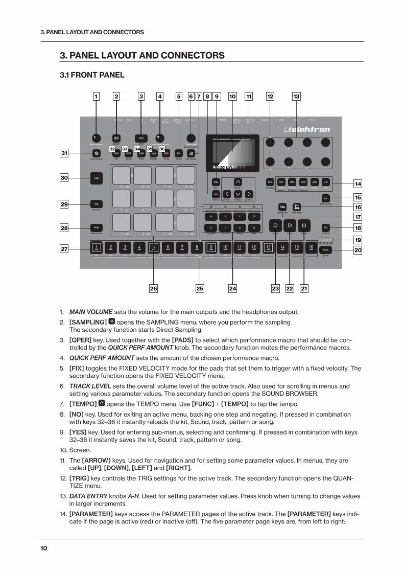
1. MAIN VOLUME sets the volume for the main outputs and the headphones output.
2. [SAMPLING] opens the SAMPLING menu, where you perform the sampling. The secondary function starts Direct Sampling.
3. [QPER] key. Used together with the [PADS] to select which performance macro that should be con-trolled by the QUICK PERF AMOUNT knob. The secondary function mutes the performance macros.
4. QUICK PERF AMOUNT sets the amount of the chosen performance macro.
5. [FIX] toggles the FIXED VELOCITY mode for the pads that set them to trigger with a fixed velocity. The secondary function opens the FIXED VELOCITY menu.
6. TRACK LEVEL sets the overall volume level of the active track. Also used for scrolling in menus and setting various parameter values. The secondary function opens the SOUND BROWSER.
7. [TEMPO] opens the TEMPO menu. Use [FUNC] + [TEMPO] to tap the tempo.
8. [NO] key. Used for exiting an active menu, backing one step and negating. If pressed in combination with keys 32–36 it instantly reloads the kit, Sound, track, pattern or song.
9. [YES] key. Used for entering sub-menus, selecting and confirming. If pressed in combination with keys 32–36 it instantly saves the kit, Sound, track, pattern or song.
10. Screen.
11. The [ARROW] keys. Used for navigation and for setting some parameter values. In menus, they are called [UP], [DOWN], [LEFT] and [RIGHT].
12. [TRIG] key controls the TRIG settings for the active track. The secondary function opens the QUAN-TIZE menu.
13. DATA ENTRY knobs A-H. Used for setting parameter values. Press knob when turning to change values in larger increments.
14. [PARAMETER] keys access the PARAMETER pages of the active track. The [PARAMETER] keys indi-cate if the page is active (red) or inactive (off). The five parameter page keys are, from left to right:

3. PANEL LAYOUT AND CONNECTORS
11
SRC key accesses the SYNTH parameters of the track Sound. These control the drum synthesis. When the FX track is active, the DELAY parameter page is accessed. The secondary function opens the MA-CHINE selection menu. SMPL key takes you to the SAMPLE page. Various aspects of the sample playback are set on this page. When the FX track is active, the REVERB parameter page is accessed. The secondary function opens the SAMPLE selection menu. FLTR key accesses the FILTER page. The analog multimode filter parameters are set here. When the FX track is active, the DISTORTION parameter page is accessed. The secondary function opens the SOUND SETTINGS menu. AMP key takes you to the AMP page, where the shape of the amplitude envelope is set. When the FX track is active, the COMPRESSOR parameter page is accessed. LFO key accesses the LFO parameters for the active track.
15. [FX] selects the FX track. Th secondary function opens the MIDI CONFIG menu.
16. [SONG MODE] activates/deactivates SONG mode. The secondary function is SONG edit.
17. [CHAIN MODE] activates/deactivates CHAIN mode. The secondary function initiates a new CHAIN.
18. [FILL] Activates FILL mode (when GRID RECORDING mode is not active). The secondary function cues the FILL mode.
19. <PATTERN PAGE> LEDs indicate how many pattern pages the active pattern consists of and which pattern page is currently active. The LED flashes on the pattern page that is currently playing.
20. [PAGE] selects the active pattern page, if the pattern has more than 16 steps. The secondary function opens the SCALE menu.
21. [STOP] stops playback. The secondary function is a paste operation.
22. [PLAY] starts the playback of the sequencer. The secondary function is a clear operation.
23. [RECORD] key. Activates/deactivates GRID RECORDING mode. Keep [RECORD] pressed, then press [PLAY], to activate LIVE RECORDING mode. Activate/deactivate QUANTIZATION of LIVE RECORDING by keeping [RECORD] pressed, then tapping [PLAY] twice. The secondary function is a copy operation.
24. [BANK A–H] selects between banks A–H.
25. <PATTERN MODE> LEDs indicate the currently selected PATTERN mode.
26. [PADS] have many possible functions depending on which mode is active and what each pad is set to do. The primary function is to play the track Sounds. Each drum track has a dedicated pad. <PADS> exhibits a variety of colors depending on what mode the Analog Rytm MKII is in and what the pads are used for.
27. [TRIG] keys are used for entering or removing sequencer trigs, in combination with the [PADS], and pa-rameter locks, in combination with the DATA ENTRY knobs. They are also used to select a pattern when one of the [BANK] keys are pressed.
28. [RTRG] key will if pressed in combination with one of the [PADS], continuously retrig the Sound. It also lets you assign custom retrigs for each of the drum tracks on a side menu appearing on the screen whenever the key is pressed. The secondary function opens the CLICK TRACK menu.
29. [TRK] key. Press [TRK] + one of the [PADS] to select a drum track for editing or CHROMATIC play. Note that the FX track has a separate dedicated key. The secondary function saves the current kit.
30. [FUNC] key. Press and hold for accessing secondary functions for some of the other keys. The secondary functions are written in blue text on the panel.
31. [GLOBAL SETTINGS] opens the GLOBAL SETTINGS menu. The secondary function opens the SAVE PROJECT menu. A long press opens the LOAD PROJECT menu.
32. [PLAY MODE] activates the PLAY mode, in which the pads are used to play the current sound loaded to every pad. The secondary function opens the KIT menu.
33. [MUTE] activates the MUTE mode. The secondary function opens the SOUND menu.
34. [CHRO] activates the CHROMATIC mode, in which the pads are used to play the current track Sound chromatically across four octaves. The secondary function opens the TRACK menu.
35. [SCNE] activates the SCENE mode, in which a one-push instant change of an array of parameter set-tings is possible. The secondary function opens the PATTERN menu.
36. [PERF] activates PERFORMANCE mode. The secondary function opens the SONG menu.

3. PANEL LAYOUT AND CONNECTORS
12
3.2 REAR CONNECTORS
1 32 4 5 6 7 8 9 10 11 12
1. POWER. Turns the unit on and off.
2. DC IN. Use the included Elektron PSU-3b power adapter, connected to a power outlet.
3. USB. Use an A to B USB 2.0 connector cable to a computer host.
4. EXP/CV IN. Input for expression pedal or CV. Use standard 1/4” mono phone plug for CV signals.
5. MIDI THRU/SYNC B. Forwards data from MIDI IN. Can also be configured to send DIN sync to legacy instruments. Use a standard MIDI cable to connect another MIDI device in the chain.
6. MIDI OUT/SYNC A. MIDI data output. Can also be configured to send DIN sync to legacy instruments. Use a standard MIDI cable to connect to MIDI In of an external MIDI device.
7. MIDI IN. MIDI data input. Use a standard MIDI cable to connect to MIDI Out of an external MIDI device.
8. AUDIO IN L/R. Inputs for sampling or sound card use. Use 1/4” mono phone plugs (unbalanced connection).
9. TRACK OUT. Individual drum voice outputs. Use either 1/4” mono phone plugs (unbalanced connection) or 1/4” (Tip/Ring/Sleeve) phone plugs (balanced connection).
10. EXT IN L/R. Use 1/4” mono phone plugs (unbalanced connection) to input sound from an external audio source.
11. MAIN OUT L/R. Use either 1/4” mono phone plugs (unbalanced connection) or 1/4” (Tip/Ring/Sleeve) phone plugs (balanced connection).
12. HEADPHONES OUT. Connect standard headphones with 1/4” stereo phone plug.
3.3 SETTING UP AND STARTING THE ANALOG RYTM MKIIMake sure you place the Analog Rytm MKII on a stable support, such as a sturdy table with sufficient cable space or mount on a rack capable of a 3 kg load.
Before you connect the Analog Rytm MKII to other equipment, make sure all units are switched off.
Plug the included PSU-3b adapter to a power outlet and insert the small plug into the Analog Rytm MKII DC IN connector.
Connect the Main Out L/R from the Analog Rytm MKII to your mixer or amplifier.
If you want to use MIDI in conjunction with your Analog Rytm MKII, connect the MIDI OUT port of the device you wish to send data from to the MIDI IN port of the Analog Rytm MKII. The MIDI THRU port duplicates the data arriving at the MIDI IN port, and you can use it for chaining several MIDI units together.
Switch on all units. Switch on the Analog Rytm MKII by pressing the Power rocker switch located at the back of the unit. Wait 2 seconds after the screen goes out before restarting the unit.
4. ANALOG RYTM MKII SOUND ARCHITECTURE
13
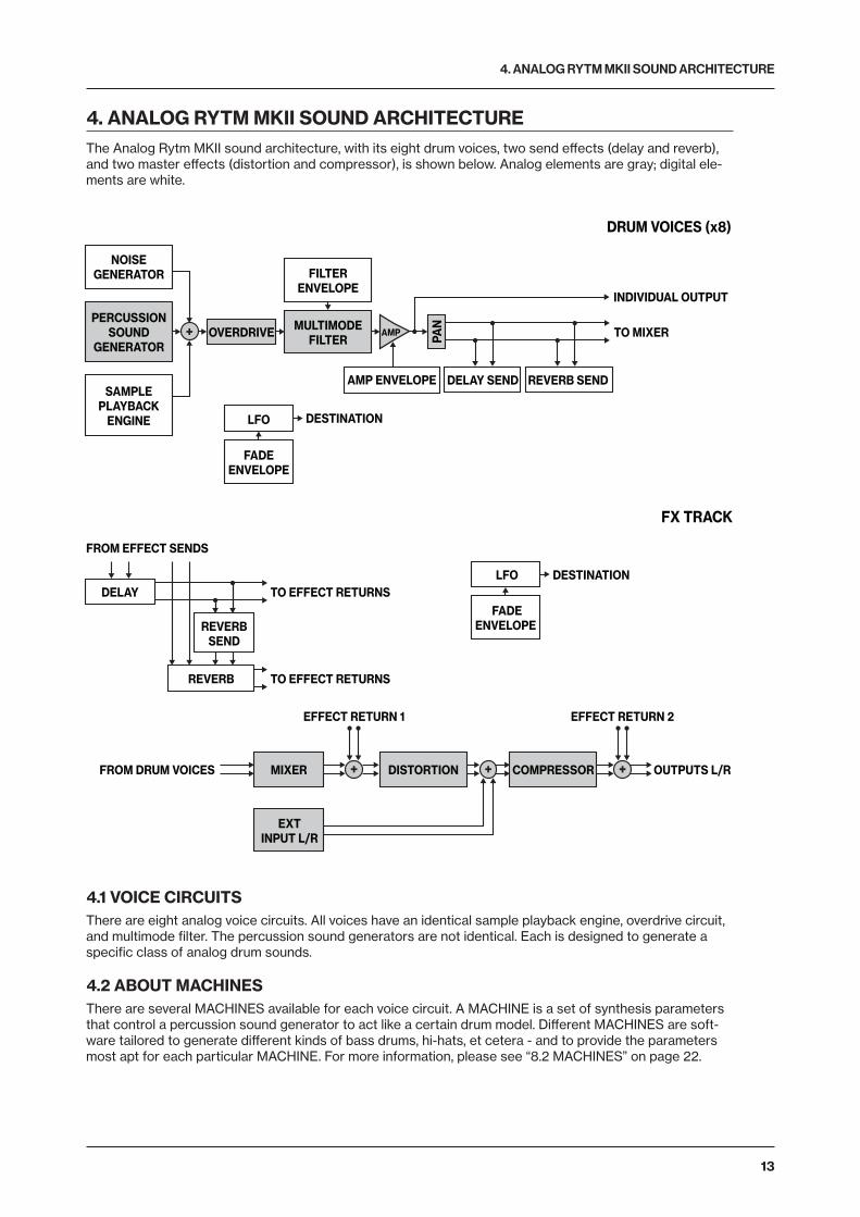
4. ANALOG RYTM MKII SOUND ARCHITECTUREThe Analog Rytm MKII sound architecture, with its eight drum voices, two send effects (delay and reverb), and two master effects (distortion and compressor), is shown below. Analog elements are gray; digital ele-ments are white.
PERCUSSIONSOUND
GENERATOR
SAMPLEPLAYBACK
ENGINE
OVERDRIVE MULTIMODEFILTER
MIXER
EXTINPUT L/R
DISTORTION COMPRESSOR
AMP
NOISEGENERATOR FILTER
ENVELOPE
AMP ENVELOPE
REVERBSEND
DELAY
REVERB
FROM EFFECT SENDS
EFFECT RETURN 1
FROM DRUM VOICES OUTPUTS L/R
EFFECT RETURN 2
TO EFFECT RETURNS
FADEENVELOPE
LFO DESTINATION
FADEENVELOPE
LFO DESTINATION
TO EFFECT RETURNS
DRUM VOICES (x8)
FX TRACK
PAN
DELAY SEND REVERB SEND
TO MIXER
INDIVIDUAL OUTPUT
4.1 VOICE CIRCUITSThere are eight analog voice circuits. All voices have an identical sample playback engine, overdrive circuit, and multimode filter. The percussion sound generators are not identical. Each is designed to generate a specific class of analog drum sounds.
4.2 ABOUT MACHINESThere are several MACHINES available for each voice circuit. A MACHINE is a set of synthesis parameters that control a percussion sound generator to act like a certain drum model. Different MACHINES are soft-ware tailored to generate different kinds of bass drums, hi-hats, et cetera - and to provide the parameters most apt for each particular MACHINE. For more information, please see “8.2 MACHINES” on page 22.

5. OVERVIEW OF THE ANALOG RYTM MKII DATA STRUCTURE
14
5. OVERVIEW OF THE ANALOG RYTM MKII DATA STRUCTUREThe image below outlines the data structure of the Analog Rytm MKII.
MASTER/SEND FX 12 DRUM SOUNDS
12 SONGS 128 PATTERNS 128 KITS 128 SOUNDS 127 SAMPLES
4 GLOBALS
PROJECT +DRIVE128 PROJECTS
SOUND LIBRARYSAMPLEBANK
5.1 +DRIVEThe +Drive is a non-volatile storage. It keeps up to 128 projects (thousands of patterns, kits and songs) stored internally. The +Drive also contains the +Drive Sound library, capable of storing 4096 drum Sounds, and the Sample bank. All projects have access to these Sounds and samples.
5.2 DATA STRUCTURE
5.2.1 PROJECTA project contains 128 patterns, 128 kits, 16 songs, 4 global slots, 127 sample slots and a project Sound pool consisting of up to 128 Sounds. General settings and states are stored in the project. When a project is loaded it becomes the active working state of the Analog Rytm MKII. From here it is possible to edit the patterns, kits, songs, and globals of the project. Every time the Analog Rytm MKII is switched on, it boots to the active working state, the active project. Projects are saved, loaded and managed in the GLOBAL SETTINGS menu. Read more about projects in the section “9. PROJECTS” on page 24.
5.2.2 KITSA kit is a collection of twelve drum track Sounds and the FX track parameter settings. When editing a track, changes made to the parameter settings is stored in the active kit. Each project of the Analog Rytm MKII contains 128 individual kits. A pattern always links to one of the kits. Read more in the section “10. KITS AND SOUNDS” on page 26.
5.2.3 SOUNDSA Sound consists of the parameter settings found in the PARAMETER pages SRC, SMPL, FLTR, AMP, and LFO. Sounds are stored in the Sound pool of the active project or the +Drive Sound library. The Sound pool has 128 Sound slots and the +Drive Sound library holds up to 4096 sounds. Read more in the section “10. KITS AND SOUNDS” on page 26.
5.2.4 SAMPLESYou can load up to 64 MB (about 11 minutes) of samples in a project, using a maximum of 127 sample slots. There are many preset samples to choose from in the +Drive Sample bank. Additional samples can be transferred to the Analog Rytm MKII from a computer with the Elektron Transfer software. You can also sample straight into the Analog Rytm MKII. See section “14. GLOBAL SETTINGS MENU” on page 54, and “13. SAMPLING” on page 52.
5.2.5 PATTERNSFor each of the 8 banks, 16 patterns are available, which means 128 patterns are always readily available for each project. A pattern contains sequencer data like drum trigs, trig mutes and parameter locks for the drum tracks and the FX track, as well as default settings on the TRIG page and length, swing, and time signature settings. Read more in the section “11. THE SEQUENCER” on page 37.

5. OVERVIEW OF THE ANALOG RYTM MKII DATA STRUCTURE
15
5.2.6 SONGS16 songs are available for each project. They are used to sequence the playback of patterns. Songs are built of patterns and chains. Read more about songs in the section “12.2 SONGS” on page 49.
5.2.7 GLOBALSThe GLOBAL settings contain overarching settings for the sequencer, MIDI, and global track routing. Four global slots are available for each project, each with its specific settings. Read more about the glob-al settings in the section “14. GLOBAL SETTINGS MENU” on page 54.
5.3 ABOUT THE TRACKS
5.3.1 THE DRUM TRACKSThere are 12 drum tracks. To select a track for editing, press and hold [TRK] key and then press one of the [PADS]. Each drum track uses a specific drum voice controlled by one of the MACHINES available for the voice. All drum tracks can layer analog percussion sounds and sampled sounds, to distort and filter them, and apply a dedicated LFO each.
5.3.2 THE FX TRACKThe FX track controls the Analog Rytm MKII send effects DELAY and REVERB, as well as the DISTOR-TION and COMPRESSOR master effects. One LFO is also available for this track. To select the FX track for editing, press the [FX] key.
5.3.3 EDITING THE TRACKSThe five [PARAMETER] keys open parameter pages that are used for editing the tracks. The SRC page of a drum track contains different parameters depending on the MACHINE chosen for the analog percus-sion sound generator. The other pages are identical for all drum tracks; the SMPL page for the sample playback engine, the FLTR page for the multimode filter and its filter envelope, the AMP page for the am-plitude envelope and effect sends, and the LFO page for the low-frequency oscillator. The corresponding five parameter pages for the FX track controls the four effects and the FX LFO. Edit parameters using the DATA ENTRY knobs A-H. Press and turn a knob to adjust its parameter in larger increments.
6. THE USER INTERFACE
16
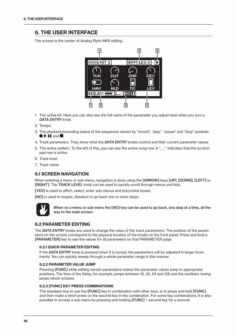
6. THE USER INTERFACEThe screen is the center of Analog Rytm MKII editing.
2 31
4567
1. The active kit. Here you can also see the full name of the parameter you adjust here when you turn a DATA ENTRY knob.
2. Tempo.
3. The playback/recording status of the sequencer shown by “record”, “play”, “pause” and “stop” symbols; , , , and .
4. Track parameters. They show what the DATA ENTRY knobs control and their current parameter values
5. The active pattern. To the left of this, you can see the active song row. A “_ _:” indicates that the scratch pad row is active.
6. Track level.
7. Track name.
6.1 SCREEN NAVIGATIONWhen entering a menu or sub-menu, navigation is done using the [ARROW] keys [UP], [DOWN], [LEFT] or [RIGHT]. The TRACK LEVEL knob can be used to quickly scroll through menus and lists.
[YES] is used to affirm, select, enter sub-menus and tick/untick boxes.
[NO] is used to negate, deselect or go back one or more steps.
When on a menu or sub-menu the [NO] key can be used to go back, one step at a time, all the way to the main screen.
6.2 PARAMETER EDITINGThe DATA ENTRY knobs are used to change the value of the track parameters. The position of the param-eters on the screen correspond to the physical location of the knobs on the front panel. Press and hold a [PARAMETER] key to see the values for all parameters on that PARAMETER page.
6.2.1 QUICK PARAMETER EDITINGIf the DATA ENTRY knob is pressed when it is turned, the parameters will be adjusted in larger incre-ments. You can quickly sweep through a whole parameter range in this manner.
6.2.2 PARAMETER VALUE JUMPPressing [FUNC] while editing certain parameters makes the parameter values jump to appropriate positions. The time of the Delay, for example, jumps between 16, 32, 64 and 128 and the oscillator tuning jumps whole octaves.
6.2.3 [FUNC] KEY PRESS COMBINATIONSThe standard way to use the [FUNC] key in combination with other keys, is to press and hold [FUNC] and then make a short press on the second key in the combination. For some key combinations, it is also possible to access a sub-menu by pressing and holding [FUNC] + second key for a second.
6. THE USER INTERFACE
17
6.3 QUICK SCROLLINGScroll through menus using the TRACK LEVEL knob. Quick scrolling is possible on many menus. Press [FUNC] + the [UP] or [DOWN] arrow keys to move the cursor one menu page at a time.
6.4 COPY, CLEAR AND PASTECopy, clear and paste commands are available in many contexts. Press [FUNC] + [RECORD] to perform a copy operation. Press [FUNC] + [STOP] to perform a paste operation. Press [FUNC] + [PLAY] to perform a clear operation. Paste and clear operations are undone by repeating the key press combination. Please see the different sections in the manual for more information on when these commands are applicable.
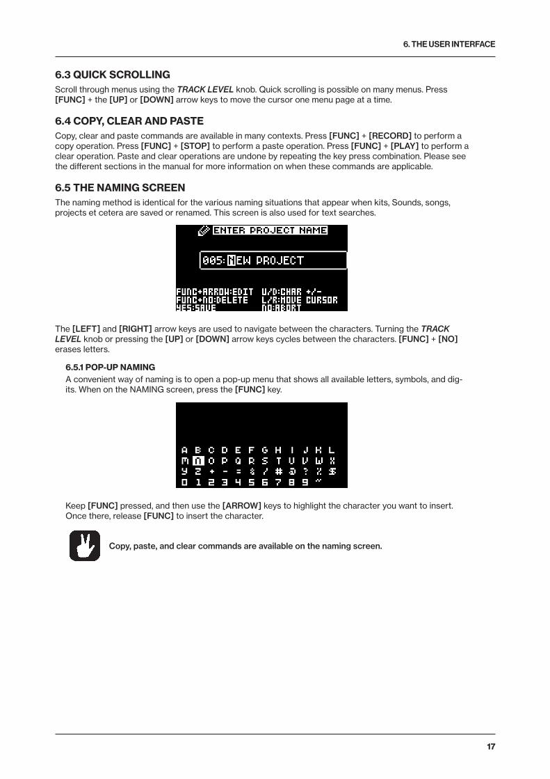
6.5 THE NAMING SCREENThe naming method is identical for the various naming situations that appear when kits, Sounds, songs, projects et cetera are saved or renamed. This screen is also used for text searches.
The [LEFT] and [RIGHT] arrow keys are used to navigate between the characters. Turning the TRACK LEVEL knob or pressing the [UP] or [DOWN] arrow keys cycles between the characters. [FUNC] + [NO] erases letters.
6.5.1 POP-UP NAMINGA convenient way of naming is to open a pop-up menu that shows all available letters, symbols, and dig-its. When on the NAMING screen, press the [FUNC] key.
Keep [FUNC] pressed, and then use the [ARROW] keys to highlight the character you want to insert. Once there, release [FUNC] to insert the character.
Copy, paste, and clear commands are available on the naming screen.
6. THE USER INTERFACE
18
6.6 OVERBRIDGE
USB
Direct
Kit Sound Track Pattern Song Setup Tap TempoSave Project
Save Kit
MIDI Config
New Chain Edit SongSequential Direct Start Direct Jump Temp Jump
Metronome Trig Mute
Scale
Accent Swing Slide Copy Clear Paste Cue Fill
Mute
Sound Browser
Assign Samples SettingsQuantize
BD SD RS CP BT LT MT HT CH OH CY CB
Main Out Ext In Audio In MIDI In MIDI Out MIDI Thru Control InBD LT CH/OHRS/CP USB DC In Power
Delay Reverb Dist Comp LFO
Sync BSync ASD MT/HT CY/CBBT
Main Volume
A
E F G H
B C D
Quick Perf Amount Track Level
1 BD 2 SD 3 RS 4 CP
5 BT 6 LT 7 MT 8 HT
9 CH 10 OH 11 CY 12 CB Save
Reload
Retrig +
Retrig -µTime - µTime +
2 3 4 5 6 7 8 9 10 11 12 13 14 15 16
A B C D
E F G H
YES
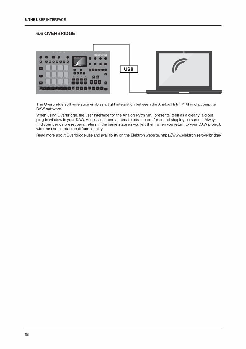
The Overbridge software suite enables a tight integration between the Analog Rytm MKII and a computer DAW software.
When using Overbridge, the user interface for the Analog Rytm MKII presents itself as a clearly laid out plug-in window in your DAW. Access, edit and automate parameters for sound shaping on screen. Always find your device preset parameters in the same state as you left them when you return to your DAW project, with the useful total recall functionality.
Read more about Overbridge use and availability on the Elektron website: https://www.elektron.se/overbridge/
7. QUICK START
19
7. QUICK STARTThis quick start guides you through some of the basic operations to start using the Analog Rytm MKII right away. First, connect it as described in section “3.3 SETTING UP AND STARTING THE ANALOG RYTM MKII” on page 12.
7.1 PLAYING THE FACTORY PRESETSYou find several preset patterns, kits, and Sounds in the Analog Rytm MKII. Follow the instructions below to get started exploring your new instrument.
1. Press [PLAY] to listen to pattern A01.
2. Press [BANK A] + [TRIG 2] to select pattern A02, which is the second demo pattern. Pattern A02 starts to play when pattern A01 reaches it end. Press [BANK A] + [TRIG 3] to select pattern A03 and so on.
3. Press [MUTE] + the [PAD] of the drum track you want to mute. Unmute by repeating the procedure.
4. Press [STOP] to stop playback.
7.1.1 PERFORMANCE MODEThe PERFORMANCE mode enables each one of the twelve pads to control several PARAMETER page parameters at once. Change many dimensions of one or more drum track Sounds at the touch of a single pad. A set of such parameter locks is called a performance macro, shown with dim green <PADS>. Try out the preset macros:
1. Make sure a pattern is playing.
2. Press the [PERF] key to enter PERFORMANCE mode.
3. Press the dim green [PADS]. Apply different pressures and hear how the sound of the pattern changes.
7.1.2 SCENE MODEThe SCENE mode turns the twelve pads into instant sound shifters. Similar to a performance macro, several parameters from any track can be changed by pressing a single pad. A scene is a fixed set of parameter values, ready to be activated or deactivated, shown with dim blue <PADS>. Try out the preset scenes by following the instructions below. A bright blue color pad shows the active scene.
1. Make sure a pattern is playing.
2. Press the [SCNE] key to enter SCENE mode.
3. Tap one of the dim blue color [PADS] to activate a scene. Tap again to deactivate.
7.1.3 CHROMATIC MODEAny track Sound may be played chromatically using the 12 pads. The chromatic note pitch is increased linearly for each successive pad pressed: left to right, bottom to top. Twelve successive pads make one octave. The range spans four octaves, middle, one up and two down. The middle octave has sky blue color <PADS>, the two below are of violet and dark blue color, in that order, and the one above is yellow.
1. Select the drum track to play chromatically by pressing [TRK] + one of the [PADS].
2. Press the [CHRO] key to enter CHROMATIC mode.
3. Play the [PADS]. The active track Sound will be pitched differently for each of the 12 pads comprising the middle octave. Reach higher or lower octaves, one row at a time, by pressing [ARROW] keys [UP] or [DOWN], respectively.
The CHROMATIC mode is an effective way to add musical variety to your beats. The timbre, tonality, and impact of playing a Sound chromatically depend on the track type and how the Sound is designed. The synth part, the sample part or both synth and sample part of the Sound may be chromatic enabled. This is done in the SOUND SETTINGS. For more information, please see “10.5.2 SOUND MANAGER” on page 32.
7.1.4 MUTE MODEYou can mute the sequencer of any of the twelve drum tracks in this mode. Unlike the CHROMATIC mode, it makes no difference which track is active when this mode is activated. All tracks are accessed simultaneously.
1. Make sure a pattern is playing.
2. Press the [MUTE] key to enter MUTE mode.

7. QUICK START
20
3. Press any of the [PADS] to mute the corresponding track. Press again to unmute. The color of the <PADS> indicates the mute status. Unlit <PADS> are muted. Green <PADS> are audible.
4. Press and hold [FUNC] and then any of the [PADS] to preselect a mute, or mute/unmute sever-al tracks in one go. Once you release [FUNC], the selected mutes come into effect. Blue colored <PADS> show the preselected mutes.
When MUTE mode is active, press [RTRG] and one of the [PADS] if you wish to activate solo, in other words, mute all tracks except the one selected. Press again to deactivate solo. Keeping [RTRG] pressed, multiple tracks may be solo activated/deactivated. Solo activated <PADS> are of turquoise color.
7.1.5 TEMPOTo change the overall BPM setting, open the TEMPO screen by pressing the [TEMPO] key.
Use the TRACK LEVEL knob to change tempo in steps of one BPM. Pressing the knob while turning it changes the tempo eight steps at a time. The [ARROW] keys [UP] or [DOWN] change the tempo steps of 0.1 BPM.
On the main interface screen, you can also press and hold [ARROW] keys [LEFT] or [RIGHT] to tempo-rarily nudge the tempo up or down by 10%. Release to revert the BPM to its original setting.
7.1.6 EDITING PARAMETERSEach drum track has five PARAMETER pages, accessed by pressing the [SRC], [SMPL], [FLTR], [AMP], and [LFO] keys. The parameters found here affect the sound in various ways. When the FX track is active, the corresponding PARAMETER pages are DELAY, REVERB, DISTORTION, COMPRESSOR, and LFO, accessed by the same keys.
1. Make sure a pattern is playing.
2. Press [TRK] + [PADS] 1–12 to select one of the twelve drum tracks.
3. To change, for example, the cutoff of the filter, press the FILTER key. The display then shows the FIL-TER page. The parameter labeled FRQ changes the cutoff of the filter. Turn DATA ENTRY knob E to change the parameter value, and hear how the Sound is affected.
Try out the rest of the PARAMETER page parameters to explore a variety of sound shaping possibilities.
To reload the Sound to its original state, press [NO] + [MUTE].
To reload the whole kit to its original state, press [NO] + [PLAY MODE].
To save kit changes, press [YES] + [PLAY MODE].
8. ANALOG RYTM MKII CONTROLS
21
8. ANALOG RYTM MKII CONTROLSThe Analog Rytm MKII is played using the [PADS]. The responsive, velocity and pressure sensitive pads can be assigned to perform many possible functions. The <PADS> can display a variety of colors. There are a variety of modes: PLAY mode, MUTE mode, CHROMATIC mode, SCENE mode and PERFORMANCE mode.
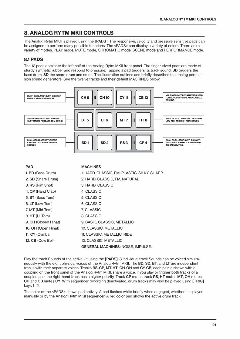
8.1 PADSThe 12 pads dominate the left half of the Analog Rytm MKII front panel. The finger-sized pads are made of sturdy synthetic rubber and respond to pressure. Tapping a pad triggers its track sound. BD triggers the bass drum, SD the snare drum and so on. The illustration outlines and briefly describes the analog percus-sion sound generators. See the twelve tracks and their default MACHINES below.
MULTI-OSCILATOR SYNTHESIS FOR HIHAT SOUND GENERATION.
SINGLE-OSCILLATOR SYNTHESIS CUSTOMIZED FOR BASS TOM SOUND.
DUAL-OSCILLATOR SYNTHESIS CAPABLE OF A WIDE RANGE OF SOUNDS.
MULTI-OSCILATOR SYNTHESIS SUITED FOR VARIOUS CYMBAL AND COWBELL SOUNDS.
SINGLE-OSCILLATOR SYNTHESIS FOR LOW- MID- AND HIGH TOM SOUNDS.
DUAL-OSCILLATOR SYNTHESIS WITH ADDITIONAL RIMSHOT SOUND SHAP-ING CAPABILITIES.
CH 9 OH 10 CY 11 CB 12
BT 5
BD 1 SD 2 RS 3 CP 4
LT 6 MT 7 HT 8
PAD
1. BD (Bass Drum)
2. SD (Snare Drum)
3. RS (Rim Shot)
4. CP (Hand Clap)
5. BT (Bass Tom)
6. LT (Low Tom)
7. MT (Mid Tom)
8. HT (Hi Tom)
9. CH (Closed Hihat)
10. OH (Open Hihat)
11. CY (Cymbal)
12. CB (Cow Bell)
MACHINES
1. HARD, CLASSIC, FM, PLASTIC, SILKY, SHARP
2. HARD, CLASSIC, FM, NATURAL
3. HARD, CLASSIC
4. CLASSIC
5. CLASSIC
6. CLASSIC
7. CLASSIC
8. CLASSIC
9. BASIC, CLASSIC, METALLIC
10. CLASSIC, METALLIC
11. CLASSIC, METALLIC, RIDE
12. CLASSIC, METALLIC
GENERAL MACHINES: NOISE, IMPULSE.
Play the track Sounds of the active kit using the [PADS]. 8 individual track Sounds can be voiced simulta-neously with the eight physical voices of the Analog Rytm MKII. The BD, SD, BT, and LT are independent tracks with their separate voices. Tracks RS-CP, MT-HT, CH-OH and CY-CB, each pair is shown with a coupling on the front panel of the Analog Rytm MKII, share a voice. If you play or trigger both tracks of a coupled pair, the right-hand track has a higher priority. Track CP mutes track RS, HT mutes MT, OH mutes CH and CB mutes CY. With sequencer recording deactivated, drum tracks may also be played using [TRIG] keys 1-12.
The color of the <PADS> shows pad activity. A pad flashes white briefly when engaged, whether it is played manually or by the Analog Rytm MKII sequencer. A red color pad shows the active drum track.

8. ANALOG RYTM MKII CONTROLS
22
8.2 MACHINESSelect a drum track MACHINE by quickly pressing the [SRC] key twice or press [FUNC] + [SRC]. A MA-CHINE makes use of the physical percussion sound generator of the voice circuit in a certain way, to make a characteristic drum model.
For example, the BD track uses the sound generator of the first voice circuit. Its default BDHD MACHINE includes one tunable analog oscillator, a choice of three different waveforms and a custom envelope to shape the sound. These MACHINE-specific synthesis parameters are on the SRC parameter page. If you select another MACHINE, it engages the sound generator differently - employing more than one oscillator, for example - enabling the BD track to perform frequency modulation and many other sound generating techniques.
All MACHINES cannot be accessed from all tracks since the tracks control different physical sound gen-erators. The illustration above shows the tracks that can make use of a specific type of percussion sound generator within the boundaries of the same gray-shaded box. For a more comprehensive list of MA-CHINES, the tracks that can use them and the specific SRC page parameters they give access to, please see “APPENDIX D: MACHINES” on page 88.
8.3 ROTARY ENCODERSThe eight DATA ENTRY knobs, the TRACK LEVEL, the QUICK PERF AMOUNT knob, and the MAIN VOL-UME knob are made of sturdy two-component plastic with a shape designed to fit snugly between thumb and forefinger, and a rubbery surface to prevent slipping. The MAIN VOLUME and QUICK PERF AMOUNT are absolute encoders, spanning roughly 320 degrees from left extreme to right extreme. A small white dot on its top surface shows the encoders position. The TRACK LEVEL and DATA ENTRY knobs (with which you set various parameter values for the active kit) are relative encoders that can be rotated any number of turns. Pressing and turning these encoders changes their associated values at a higher speed.
8.4 PRAGMATIC OPERATIONThe functional layout of the Analog Rytm MKII front panel ensures many complex operations can be done using only one hand, leaving the other hand free to tweak sounds. With all mode and track keys near each other, one-handed track muting, chromatic play, scene change, and performance macro deployment are possible. As is one-handed retrigging, tempo tapping, pattern mode change, and pattern selection.
8.5 KEY BEHAVIORAs a group, the track selection keys ([TRK] + any of the [PADS] and the [FX] key) have radio button func-tionality, i.e., when a new track is set to be active, the previous one is simultaneously deactivated (one and only one track must always be selected). Likewise, the group that consists of the five [PARAMETER] keys and the [TRIG] key has radio button functionality.
The mode keys [PLAY MODE], [MUTE], [CHRO], [SCNE] and [PERF] keys have both on/off and radio button functionality (which means they can all be switched off, but only one of them can be on at the same time). This behavior goes for the [SONG MODE] and [CHAIN MODE] keys as well.
The [TRK], [FUNC] and [RTRG] keys must be pressed in combination with other keys to exert functionality.
8.6 MIDI NOTESSome functions can be triggered by sending MIDI note values from an external MIDI device (a MIDI key-board or a computer, for example) connected to the Analog Rytm MKII via standard MIDI cable or a USB 2.0 A to B connector cable.
Of the 128 notes in the standard MIDI range, 0–11 corresponds to notes C0 through to B0, the leftmost oc-tave (which is sometimes called C-2–B-2 in certain applications) will trigger the Sound of track 1 through to track 12, respectively (provided they are set to their default channels 1–12). These note values map to each of the twelve tracks, regardless of which track is active.
MIDI note values 12–59 (corresponding to notes C1–B4, the second through to the fifth octave in the MIDI range) will trigger the Sound of the active track in any of its 48 chromatic variations (as if played by the pads in CHROMATIC mode, see section below), from lowest to highest pitch. The track Sound must be enabled for chromatic play if any variation is to be heard. Activate via the SOUND SETTINGS. For more information, please see “10.5.2 SOUND MANAGER” on page 32.
MIDI program change messages 0–127 selects pattern 1–128 (A01–H16) on the Analog Rytm MKII. Addition-ally, MIDI CC and NRPN messages can be sent to control various aspects of the Analog Rytm MKII. See “APPENDIX C: MIDI” on page 79 for a complete specification.

8. ANALOG RYTM MKII CONTROLS
23
8.7 MODE KEYSThere are five main keys with which you select the mode of operation on the Analog Rytm MKII: [PLAY MODE], [MUTE], [CHRO], [SCNE] and [PERF].
8.7.1 PLAY MODETo activate the PLAY MODE mode, press the [PLAY MODE] key. In PLAY MODE the pads are used to play the drum Sounds that is loaded to their corresponding track.
8.7.2 MUTE MODETo activate the MUTE mode, press the [MUTE] key. You can mute the sequencer of any of the twelve drum tracks in this mode. Press any of the [PADS] to mute the corresponding track. Press again to un-mute. The color of the <PADS> indicates the mute status. Muted <PADS> are unlit. Audible pads <PADS> are green.
Press and hold [FUNC] and then any of the [PADS] to preselect a mute, or mute/unmute several tracks in one go. Once you release [FUNC], the selected mutes come into effect. Blue color <PADS>. show preselected mutes
Press [RTRG] and one of the [PADS] if you wish to activate solo, in other words, mute all tracks except the one selected. Press again to deactivate solo. Keeping [RTRG] pressed, multiple tracks may be solo activated/deactivated. Solo activated <PADS> are turquoise.
The tracks you have muted in this mode stay muted even if you change the pattern or load a new kit. After exiting MUTE mode, the [MUTE] key stays lit, half-bright red if any of the tracks are muted. The MUTE mode is a part of the active state of the machine. It is not stored to the current kit or pattern. Mutes activated in MUTE mode are the master mutes, and they override any TRIG MUTE patterns on the sequencer or any SONG MUTE program on any pattern of the active song.
8.7.3 CHROMATIC MODEPressing the [CHRO] key turns the [PADS] of the Analog Rytm MKII into a chromatic keyboard. When in this mode, you can play the Sound of the active track chromatically.
Any track Sound may be played in this mode using the 12 pads. The chromatic note pitch is linearly increased for each successive pad pressed: left to right, bottom to top. Twelve pads in succession make up one octave. The range spans four octaves, middle, 1 up and 2 down. The middle octave has blue color <PADS>, the two below are of violet and dark blue color, in that order, and the one above is yellow. Reach higher or lower octaves, one row at a time, by pressing the [ARROW] keys [UP] or [DOWN], respectively.
The Synth part, the Sample part or both at once of any Sound may be chromatic enabled. This is done in the SOUND SETTINGS. For more information, please see “10.5.2 SOUND MANAGER” on page 32.
Notes trigged chromatically can be recorded on the sequencer. Find out how this is done in sections “11.3.2 GRID RECORDING MODE” on page 39 and “11.3.3 LIVE RECORDING MODE” on page 39.
Like the MUTE mode, the active state of the CHROMATIC mode (the portion of the chromatic keyboard currently visible on the pads) is not stored per kit or pattern but stays in its set state until it is changed.
8.7.4 SCENE MODEThe SCENE mode turns the twelve pads into instant sound shifters. Press a single pad to change several parameters from any track. A scene is a fixed set of parameter values, ready to be activated or deactivat-ed. To activate the SCENE mode, press the [SCNE] key.
By carefully assigning a set of parameter values, you can prepare a scene that makes the same kit sound drastically (or subtly) different whenever activated. After exiting SCENE mode, the [SCNE] key stays lit, half-bright red if any of the scenes are active. Unlike the MUTE or CHROMATIC mode, SCENE mode settings are stored in the active kit. See “10.3 SCENE MODE” on page 28.
8.7.5 PERFORMANCE MODEPress the [PERF] key to enter PERFORMANCE mode. This mode enables the [PADS] to control several PARAMETER page parameters at once. Change many dimensions of one or more drum track Sounds at the touch of a single pad. A pad in this mode, prepared with one or many additive layers of parameter modulation, is called a performance macro. While setting up a performance macro is done in a similar way as setting up a scene, there is a major difference in the way these two modes operate. A scene is a static, ON/OFF command of an array of parameters set to specific values. A performance macro engag-es the assigned parameters dynamically. When using a performance macro, the parameters are modulat-ed relative to the pressure applied to the pad.
PERFORMANCE mode settings are stored as part of a kit. For more information, please see “10.4 PER-FORMANCE MODE” on page 29.

9. PROJECTS
24
9. PROJECTSA project is the top level of the Analog Rytm MKII workflow. A project contains 128 patterns, 128 kits, and 16 songs, 4 global slots, and a project Sound pool consisting of up to 128 Sounds. Projects are handy when, for exam-ple, you want to save a specific setup for a live performance or when managing a select number of compo-sitions. The +Drive can store 128 projects.
When a project is loaded it becomes the active working state of Analog Rytm MKII, independent of the +Drive. Analog Rytm MKII keeps track of what project slot the active project was loaded from. It is possible to edit the patterns, kits, songs, and globals of a loaded project.
Within an active project, all changes made are automatically remembered by the Analog Rytm MKII, let-ting you switch back and forth between patterns and kits and edit the patterns, kits, and parameters in any order you like without the need to save each adjustment manually. Patterns, the active kit Sounds, and settings, songs and globals are remembered even after the power is turned off. However, regarding kits (the main entity for editing and collectively storing a complete set of Sounds and effects), when the Analog Rytm MKII is switched off, only the settings of the active kit are preserved. If for example, the kit linked to pattern 1 is edited (kit A), another pattern is selected and its kit edited (kit B) and then the power is turned off, only the changes to kit B (the most recent active kit) will be remembered. We highly recommend that you specif-ically save the kits you have been working on manually using the quick command [YES] + [PLAY MODE]. Find out more about kits in the section “10. KITS AND SOUNDS” on page 26.
Project changes are not automatically written to the +Drive. To store the active working state of the project to a +Drive slot, the project needs to be saved manually. See below on how to load and save projects.
9.1 PROJECT MENUProjects are managed in the PROJECT menu, located in the GLOBAL SETTINGS menu. Open the GLOBAL SETTINGS menu by pressing [GLOBAL SETTINGS].
Scroll through the list by using [UP]/[DOWN] or the TRACK LEVEL knob and select PROJECT. Open the menu by pressing [YES].
LOAD PROJECT opens a project selection screen where you choose a project to be loaded. Note that the active project will not be saved before loading the new project. This menu can be accessed directly by pressing and holding [GLOBAL SETTINGS] for a little while. If you wish to create a new project, select CREATE NEW at the very bottom of the list. The new project will be a blank slate.

9. PROJECTS
25
SAVE PROJECT opens a project selection screen where you choose a slot to save the active project to. This menu can be accessed directly by pressing [FUNC] + [GLOBAL SETTINGS].
PROJECT MANAGER launches the PROJECT MANAGER menu. Selecting a project in this menu and pressing the [RIGHT] arrow key brings up a list of commands.
CLEAR resets the project slot to a clean state.
DELETE removes the project from the slot.
RENAME opens a screen where you can rename the project file.
LOAD FROM loads the selected project. This overwrites the active project!
SAVE TO saves the active project to the selected slot.
TOGGLE toggles write protection on or off. Write-protected projects cannot be overwritten, renamed or erased. A write-protected project is shown with a padlock symbol.
INIT NEW initializes an empty file slot with a clean project. This option is only available for empty project slots.
• Multiple projects can be selected and deselected by highlighting them and pressing [YES].• The currently active project is linked to the slot shown with a small arrow in front of the
project name.• A lock symbol indicates the project is write protected.• Projects can be copied/cleared/pasted.
LOAD FROM in the PROJECT MANAGER overwrites the active project. Be sure to save your project before you load another.

10. KITS AND SOUNDS
26
10. KITS AND SOUNDSEvery project has the capacity of 128 different kits. A kit is a collection of 12 drum track Sounds and an FX track and their specific parameter settings. A Sound is composed of synth, sample, filter, effect sends, envelope and LFO settings in any combination. Sounds are assigned to the twelve drum tracks.
Each of the drum tracks contains one Sound. The PARAMETER page settings for each track in a kit can be saved as an individual Sound if so desired. A Sound that has been loaded, from the +Drive or the Sound Pool to a track, becomes a part of the active kit. Any changes made to a track Sound do not affect the stored Sound. It affects and become part of the active kit. A pattern, controlling the playback of the kit, always links to a specific kit (non-exclusively). Any changes to the kit affect other patterns using the same kit. When the Analog Rytm MKII is switched off, only the active kit preserves its changes. Other kits must be saved.
A Kit contains:
• Sound parameter settings for the 12 drum tracks.• FX track parameter settings.• LEVEL settings for the drum and FX tracks.• RETRIG settings.• General SOUND SETTINGS.• PERFORMANCE and SCENE mode macros and parameter settings.
A Sound contains:
• Settings for the PARAMETER pages of a drum track.
• The graphics in the top left part of the screen shows the name of the active kit. When you press a [TRK] key and one of the [PADS], this information briefly changes to show the name of the track Sound.
• When you create a brand new pattern, using an existing kit that is already linked to anoth-er pattern, we recommend tha t you save and rename the kit, the first thing you do (see below). Unless, of course, you intend kit changes to affect multiple patterns.
10.1 THE +DRIVE SOUND LIBRARY AND THE SOUND POOLSounds can be loaded to a kit from either the +Drive Sound library or the Sound pool of the active project. The +Drive Sound library has the capacity of 4096 Sounds, available to all projects. The Sound pool is a part of a project and can contain up to 128 Sounds. The major benefit of Sounds loaded to the Sound pool is the possibility for them to be Sound locked. This feature is not available for the Sounds in the +Drive Sound library. Read more about Sound locking in the section “11.11.2 SOUND LOCKS” on page 45.
10.2 KIT MENUIn the KIT menu, commands relating to kits are found, including kit save and kit load. Open the menu by pressing [FUNC] + [PLAY MODE]. Use the [UP] and [DOWN] arrow keys to move between the commands. Press [YES] to confirm your selection. Exit the menu by pressing [NO].
10.2.1 RELOAD KITReloads either the active kit, reverting it to its saved status or all kits. Using the [LEFT] and [RIGHT] keys selects whether only the active kit or all kits will be reloaded. [NO] + [KIT] offers a shortcut to reloading the active kit.
10.2.2 LOAD KITOpens a menu where one of the up to 128 saved kits can be loaded. The kit list will appear when this menu is accessed. The active kit is shown with inverted graphics. Select the kit you want to load by using the [ARROW] keys or the TRACK LEVEL knob. [LEFT]/[RIGHT] will quickly scroll between the menu

10. KITS AND SOUNDS
27
pages. Once a kit has been selected, press [YES] to load it. The loaded kit are linked to the active pat-tern. If the active kit is loaded, it will be reloaded to the state it was saved in.
10.2.3 SAVE KITSaves all the current kit related settings as a kit. When a kit is saved, it will be linked to the active pat-tern. [YES] + [PLAY MODE] offers a shortcut to this command, saving the kit instantly to the same slot and with the name of the kit unchanged. It is good practice to use the shortcut frequently to ensure kit changes are saved.
When this menu is opened, the kit list will appear. The active kit is shown with inverted graphics. Select the slot to which the kit will be saved by using the [ARROW] keys or the TRACK LEVEL knob. Press [YES] to save to the selected slot. The NAMING screen, covered on page 17, will appear.
10.2.4 CLEAR KITClears the content of the currently loaded kit, basically initializing it. When selecting this option a prompt will appear. Press [YES] to clear the kit or [NO] to cancel the operation. Note that no kit information will be permanently lost until the kit is saved to the same kit slot it was loaded from.
10.2.5 TRACK ROUTING KITCustomizes track routing. The default setting is to use the TRACK ROUTING global settings found in the GLOBAL SETTINGS menu. See section “14.6 TRACK ROUTING GLOBAL” on page 59.
If you want custom settings for the currently active kit, press [YES] to untick the USE GLOBAL SETTING box and use the [ARROW] keys [UP] and [DOWN] to navigate the menu.
USE GLOBAL SETTING press [YES] if you decide to use GLOBAL settings after all. The <PADS> shows what the current GLOBAL settings are for the drum tracks. <PADS> of a green color send to main. Unlit <PADS> do not.
ROUTE TO MAIN highlight this option to customize which of the 12 tracks will send to the master ef-fects (Distortion and Compressor) and main output. Use the [PADS] to activate/deactivate send from the track of each corresponding pad. <PADS> of a green color send to main. Unlit <PADS> do not. Note that each track still sends to its individual output.
SEND TO FX highlight this option to customize the send FX routing of the 12 tracks. Use the [PADS] to activate/deactivate each corresponding track for sending to the send FX (Delay and Reverb). <PADS> of a yellow color send to FX. Unlit <PADS> do not.
10.2.6 CONTROL IN 1 MODOpens the CONTROL IN 1 MOD setup for Control In 1. Basically this is like a performance macro that you can control with CV or an expression pedal connected to the Control In 1 input (labeled EXP/CV IN 1 on the Analog Rytm MKII back panel). The setup for the Control In 1 input can be found in the GLOBAL SET-TINGS menu. For more information, please see “14.7 CONTROL INPUT 1” on page 59. This modulation macro is configured the same way as a performance macro.

10. KITS AND SOUNDS
28
Up to five track parameters can be assigned to a modulation macro. Parameters can be selected from all drum tracks and the FX track. Press DATA ENTRY knobs A–E to select the track from which parameters you want to assign to the macro. Select the track parameters that will be assigned by turning DATA EN-TRY knobs A-E. Confirm a selection by clicking the knob or by pressing [YES]. DATA ENTRY knobs F-J are then used to set the depth of the five track parameters. The depth is an offset of the original track parameter value. By default, the parameter macro knob spans a parameter value range of -128–127. A parameter macro value of 0 will not introduce any changes to the sound.
The bar on the left in the screen shows a graphical representation of the incoming signal.
10.2.7 CONTROL IN 2 MODSame functions as CONTROL 1 IN MOD but for Control In 2.
• Copy, clear and paste operations are available in the LOAD KIT and SAVE KIT menus.• Use the TRACK LEVEL knob to scroll through the LOAD KIT and SAVE KIT menus.• Once you have assembled a kit you like or changed it to your liking, don’t forget to save
it using the shortcut [YES] + [PLAY MODE].• An asterisk symbol following the kit name denotes a kit that is not used by any pattern.
10.3 SCENE MODEPress [SCNE] to enter scene mode. A scene is a collection of fixed parameter locks. It enables an instant makeover of how the tracks of the active kit sound, at the touch of a single pad. 12 scenes may be assigned, one for each of the [PADS].
Press one of the [PADS] when in scene mode to activate a scene. Only one scene may be active at a time. When active, the pad to which the scene is assigned glows blue. The <PADS> of non-empty, inactive scenes glow half-bright blue. Empty scenes have unlit pads. If the pad of the active track contains a scene, the pad is violet colored (a mix of the active track color and the scene color, red and blue).
10.3.1 SCENE EDITThere are 12 assignable scenes available, one for each pad. Make sure SCENE mode is active. Select which scene to edit by pressing one of the [PADS]. Then press and hold the [SCNE] key for a short while to edit the scene.
When SCENE mode is active, [FUNC] + one of the [PADS] offers a convenient shortcut to scene edit mode.
When scene edit is active, the bottom of the screen reveals a list showing, from left to right, the scene number, the number of locked parameters, an option to clear the scene and an option to clear all scenes. Use the [ARROW] keys [LEFT] and [RIGHT] to navigate this list.
SCENE shows which scene is being edited. Use [ARROW] keys [UP] and [DOWN] to select another scene.

10. KITS AND SOUNDS
29
LOCKS shows the number of parameter locks assigned to the scene. This changes by adding or removing parameter locks (see below).
<CLEAR> clears all parameter locks assigned to the scene being edited. Press [YES] when this option is highlighted to clear the scene.
<CLEAR ALL> clears all parameter locks on all the 12 scenes. Press [YES] when this option is high-lighted to clear all scenes.
While keeping the scene pad pressed, various parameters can be locked to the scene by turning the DATA ENTRY knobs. Any parameter, from any of the 13 tracks, can be modulated and locked to the scene. Choose the drum tracks from which the parameter locks will be assigned by pressing [TRK] + [PADS]. If parameters from the FX track are to be locked to the scene, press the [FX] key. The parame-ters available for modulation and scene assignation are visible on the screen.
When a scene is edited, the pads of drum tracks containing parameter locks glows half-bright red and flicker. The active track, from which parameter locks are currently set, glows full-bright red. If a scene contains FX track parameter locks, the [FX] key flickers while editing the scene. When the scene pad is pressed during edit, parameter locks are shown with inverted graphics and their fixed values (provided the particular track, and the particular parameter page where the locked parameter is located, is active) are also shown.
A total of 48 different parameters may be locked to any of the 12 scenes, in any combination, for each kit. For example, 48 parameter locks may be used for a single scene, two scenes may use 24 parameter locks each, four scenes may use, say, 2, 4, 10 and 32 parameter locks, and so on.
The scene of each pad can be copied, pasted to another pad or cleared using [FUNC] + [RECORD]/[STOP]/[PLAY], respectively. SCENE settings are stored to the active kit. Remember to save the kit regularly with [YES] + [PLAY MODE].
Once the editing is done, simply press the [SCNE] key again to exit scene edit mode. The parameter locks you entered will be instantly enabled whenever the scene is activated.
10.4 PERFORMANCE MODEEnter PERFORMANCE mode by pressing the [PERF] key. The PERFORMANCE mode enables you to tweak one or several parameters, chosen from any track, by applying different amounts of pressure to any of the [PADS] containing a performance macro. 12 performances may be assigned, one for each of the [PADS].
• By gently increasing the amount of pressure applied to a pad containing a performance macro (or quickly pressing, and then gently releasing the applied pressure), all intermedi-ate values of the parameter lock range can be heard while going from one extreme of the modulation depth to the other.
• Press [FUNC] + [QPER] to mute the PERFORMANCE mode. This temporarily mutes all the changes that have been made to the track parameters by the performance macros. Press [FUNC] + [QPER] again to unmute the PERFORMANCE mode to let the changes affect the parameters again. The [QPER] key is green when PERFORMANCE mode is active and turned off then PERFORMANCE mode is muted.
• As the name implies, the PERFORMANCE mode is a live performance feature. As is the SCENE mode. When recording on the sequencer, PERFORMANCE mode macros and SCENES are not possible to parameter lock.
10.4.1 PERFORMANCE EDITMake sure PERFORMANCE mode is active. Press and hold the [PERF] key for a short while to enter edit mode.
There are 12 assignable performance macros available, one for each pad. Select which macro to edit by pressing one of the [PADS]. When performance edit is active, the bottom of the screen reveals a list showing, from left to right, the performance macro number, the number of locked parameters, an option to clear the macro and an option to clear all macros. Use the [ARROW] keys [LEFT] and [RIGHT] to navigate through this list.

10. KITS AND SOUNDS
30
PERF shows which performance macro is edited. Use [ARROW] keys [UP] and [DOWN] to select another performance macro to edit.
LOCKS shows the number of parameter locks assigned to the performance macro. This figure will only change by adding or removing parameter locks (see below).
<CLEAR> clears all parameter locks assigned to the performance macro that you edit. Press [YES] when this option is highlighted to clear the macro.
<CLEAR ALL> clears all parameter locks on all the 12 performance macros. Press [YES] when this option is highlighted to clear all macros.
While keeping the pad pressed, various parameters can be locked to the macro by turning the DATA ENTRY knobs. Any parameter, from any of the 13 tracks, can be locked to the macro. Choose the drum tracks from which the parameter locks will be assigned by pressing [TRK] + [PADS]. If parameters from the FX track are to be locked to the macro, press the [FX] key. The parameters available for modulation and macro assignation will be visible on the screen.
When a macro is edited, the pads of drum tracks containing parameter locks will glow half-bright red and flicker. The active track, from which parameter locks are currently set, will glow full-bright red and flicker. If a macro contains FX track parameter locks, the [FX] key will flicker while editing. When a pad contain-ing a performance macro is pressed during edit, parameter locks are shown with inverted graphics and their modulation depth values (provided the particular track, and the particular parameter page where the locked parameter is located, is active) are also shown.
A total of 48 different parameters may be locked to any of the 12 performance macros, in any combina-tion, for each kit. For example, 48 parameter locks may be used for a single macro, two macros may use 24 parameter locks each, four macros may use, say, 2, 4, 10 and 32 parameter locks, and so on.
• While the process of editing a performance macro is similar to editing a scene, the parameter locks have a completely different functionality. Whereas scene mode locks are fixed values, performance mode locks are modulation depth settings.
• If, for example, the TUN parameter on the SRC parameter page of the BD track is locked to a value of +24, the performance macro will, when engaged, perform a relative increase of the TUN setting of the track Sound between 0 and +24, depend-ing on the amount of pressure applied to the pad to which the performance macro is assigned. 0 if no pressure is applied, 12 if medium pressure is applied and 24 if maxi-mum pressure is applied.
• If the TUN parameter is locked to a value of -24 instead, no pressure will produce a relative value decrease of 0, medium pressure -12 and maximum pressure -24.
• Note that the offset is relative to the general TUN (or any other) parameter setting: if the general setting is 30, a parameter lock with a modulation depth of +24 is set, and maximum pressure is applied to the pad which contains the performance macro, the resulting value will be +54.
The macro of each pad can be copied, pasted to another pad or cleared using [FUNC] + [RECORD]/[STOP]/[PLAY], respectively. PERFORMANCE mode settings are stored to the active kit. Remember to save the kit regularly with [YES] + [PLAY MODE].
Once the editing is done, simply press the [PERF] key again to exit edit mode. The parameter locks you entered will be activated whenever the pad containing the performance macro is pressed, provided PERFORMANCE mode (but not performance edit) is active. The relative modulation depth of all locked parameters will respond to the amount of pressure applied to the pad.
10.4.2 QUICK PERFORMANCEQuick performance gives you the possibility to control one of your performance macros without being in PERFORMANCE mode. Press [QPER] + [PADS] or [QPER] + [TRIG 1–12] keys to select which perfor-mance macro you want to control with Quick performance. The [PADS] and the [TRIG 1–12] keys cor-relate to the 12 performance macros you have at your disposal. For more information, please see “10.4.1

10. KITS AND SOUNDS
31
PERFORMANCE EDIT” on page 29. Once you have selected which performance macro to control, use the QUICK PERF AMOUNT knob to control how much the performance macro will affect the tracks.
10.5 SOUND MENUIn this menu Sounds in the +Drive Sound library or the Sound pool of the active project can be browsed and managed. Other menu options let you clear the track Sound, rename the track Sound or change the set-tings for the track Sound. Open the menu by pressing [FUNC] + [MUTE]. Use the [UP] and [DOWN] arrow keys to move between the options. Press [YES] to confirm your selection. Exit the menu by pressing [NO].
10.5.1 SOUND BROWSERThe SOUND BROWSER is for previewing and loading of Sounds. Opening the menu shows a list of all Sounds in either the +Drive Sound library or the Sound pool. Only the Sounds that can be loaded to the active track will be shown. For example, if the CH track is active, only the Sounds using the MACHINES available for the CH (and OH) track is visible. If you wish to browse various Bass Drum Sounds, for in-stance, first make sure the BD is the active track by pressing [TRK] + the first [PADS] key. Scroll the list by turning the TRACK LEVEL knob or by pressing [UP]/[DOWN]. Load a Sound by pressing [YES]. Un-like the SOUND MANAGER menu, it does not have the SOUND OPERATIONS menu. Also, empty Sound slots are not shown here.
You can also double-press [TRK] to open the SOUND BROWSER.
Pressing [LEFT] accesses the SORTING menu. Press [YES] to execute the commands. Press [NO] or the [RIGHT] arrow key to exit the menu.
VIEW POOL lists Sounds available in the Sound pool of the active project. The command is only avail-able when browsing the +Drive Sound library.
VIEW +DRIVE lists Sounds available on the +Drive Sound library. The command is only available when browsing the Sound pool of the active project.
SORT ABC sorts the Sounds in alphabetical order. The command is only available when Sounds are sorted by slot number.

10. KITS AND SOUNDS
32
SORT 123 sorts the Sounds by slot number (or +Drive position). The command is only available when Sounds are sorted alphabetically.
FILTER opens a list where Sounds can be arranged according to tags. Select and deselect tags by pressing [YES]. Multiple tags can be selected. Exit the tag list by pressing [NO].
SEARCH performs a text search and list all Sounds with names matching or including the text input. See “6.5 THE NAMING SCREEN” on page 17 on how to enter text.
10.5.2 SOUND MANAGERThe SOUND MANAGER is a more comprehensive version of the SOUND BROWSER. Sounds can be saved, loaded, renamed, tagged et cetera. Opening this menu shows a list of all Sounds found in either the +Drive Sound library or the Sound pool. Unlike the browser, all Sounds will be shown, not just the Sounds that can be used by the active track. The color of the active track pad will show if the Sound can be loaded or not. Violet color means it can. Additionally, when a Sound is highlighted, the <PADS> of all tracks to which the Sound can be loaded will be shown in dim red color. Sounds can be previewed by tapping the pad of the active track, provided that the Sound can be voiced by the track (i.e. the pad color is violet) Scroll the list by turning the TRACK LEVEL knob or by pressing [UP]/[DOWN].
Pressing [LEFT] accesses the SORTING menu. The available commands are the same as those found in the SORTING menu of the SOUND BROWSER. Read more in the section “10.5.1 SOUND BROWSER” on page 31.
Pressing [RIGHT] accesses the SOUND OPERATIONS menu. The available operations affects the highlighted Sound. Press [YES] to apply the commands to the selected Sound. Press [NO] or the [LEFT] arrow key to exit the menu.
LOAD TO TRACK loads the selected Sound to the active track and makes it a part of the active kit.
COPY TO... Copies the selected sounds to one of the following:
• POOL copies the selected Sounds to the first free slots of the active project Sound pool.
• +DRIVE copies the selected Sounds to the first free slots of the +Drive Sound library.
• +BANK (A-P) copies the selected Sounds to the first free slots of a specific bank inside the +Drive.
STORE TRACK SOUND saves the active track Sound to the selected slot. Please note that outside of the SOUND MANAGER, at any time (except when in MUTE mode or SONG EDIT mode), [YES] + [MUTE] offers a shortcut to this operation.

10. KITS AND SOUNDS
33
RENAME renames the selected Sound.
EDIT TAGS opens a menu where Sounds can be tagged. Sounds can have any number of tags, but only the first two will be shown on the Sound list. Apply or remove tags by pressing [YES].
DELETE deletes the Sound.
SELECT ALL selects all Sounds in the list.
DESELECT ALL deselects all Sounds in the list.
TOGGLE enables or disables write protection for the selected Sounds. When a Sound is write pro-tected it cannot be overwritten, renamed, tagged or deleted.
SEND SYSEX sends the selected Sounds as SysEx data.
• Sounds in the +Drive Sound library are organized into 16 banks, ranging from A to P. Each bank can contain 256 Sounds. Use the [TRIG] keys to view only Sounds located in a specific bank.
• You can preview the currently selected Sound by tapping the pad of the active track. All Sounds available for the active track can be previewed. Please note that if the previewed Sound is sent to the effects, the current effects settings will affect it.
• Several Sounds can be simultaneously affected by the commands available in the SOUND OPERATIONS menu. Select/deselect individual Sounds by highlighting them and pressing [YES].
• Press [FUNC] + [UP]/[DOWN] for faster scrolling in the Sound list.
10.5.3 CLEAR TRACK SOUNDSets the PARAMETER page parameters of the active track to their default values. When choosing this option, a prompt will appear. Press [YES] to reinitialize the parameters or [NO] to cancel the operation. Note that no parameter information will be permanently lost until the kit is saved to the same slot it was loaded from.
10.5.4 RENAME TRACK SOUNDOpens a NAMING screen where the Sound of the active track can be renamed.
10.5.5 SOUND SETTINGSOpens a menu where various overarching Sound settings are found. These settings are stored to the active kit. Use the [UP]/[DOWN] arrow keys or the TRACK LEVEL knob to scroll through the menu. Use the [LEFT]/[RIGHT] arrow keys to change the settings.
MACHINE select the MACHINE with which the active track Sound will be generated. Only the MACHINES available for the active track will be shown. To swiftly change MACHINE, use the shortcut command by quickly pressing the first [PARAMETER] key, SRC, twice. To find out more about MA-CHINES, see “APPENDIX D: MACHINES” on page 88.
CHROMATIC sets which parts of the Sound CHROMATIC mode, as well as the trig page NOT param-eter, will affect:
• OFF means the pitch will not be affected at all.
• SYNTH affects the pitch of the Synth part only.
• SAMPLE affects the pitch of the Sample part only.
• SYN+SMP affects the pitch of both Synth and Sample parts.
ENV RESET sets the filter envelope behavior:
• OFF does not reset the envelopes for each consecutive trig (lets the cycle complete).
• FILTER resets the envelopes for each consecutive trig (default).

10. KITS AND SOUNDS
34
VELOCITY TO VOL select how velocity will affect volume when playing the Sound on the [PADS] or with an external MIDI unit.
• OFF means velocity will not affect the volume of the Sound.
• ON means the volume will correspond linearly to velocity.
VELOCITY MOD gives access to a menu where up to five PARAMETER page parameters can be assigned to the velocity mod parameter. Open the menu by pressing [YES]. Use DATA ENTRY knobs A-D to select parameters from any of the PARAMETER pages. Press [YES] to confirm selection. Use DATA ENTRY knobs E-H to set the modulation depth for the chosen parameters. Use the TRACK LEVEL knob to set the overarching velocity range.
AFTERTOUCH gives access to a menu where up to five PARAMETER page parameters can be as-signed to the [PADS] or external MIDI unit aftertouch command. Open the menu by pressing [YES]. Use DATA ENTRY knobs A-D to select parameters from any of the PARAMETER pages. Press [YES] to confirm selection. Use DATA ENTRY knobs E-H to set the modulation depth for the chosen param-eters. Use the TRACK LEVEL knob to set the overarching velocity range.
SMP: displays the full name of the sample loaded to the active track.
LEGACY FX SEND will when checked lower the FX send levels slightly to make Sounds made for an earlier Analog Rytm OS sound as they were intended.
• Copy, clear and paste operations are available in the SOUND BROWSER and SOUND MANAGER.
• Use the TRACK LEVEL knob for faster scrolling in the SOUND BROWSER and SOUND MANAGER.
10.6 PLAYING A SOUNDPress [PLAY MODE] to use the [PADS] to trigger the drum track Sounds, and then tap any of the [PADS] to play the Sounds of the active kit. The <PADS> will briefly flash when pressed. Each pad is velocity sensi-tive, so a gentle yap and a decisive stab on the pad will produce drum sounds of different intensities.
Use [FUNC] + [PADS] to trig the Sound at the velocity set on the trig page for each track (the VEL param-eter). You can also set the pads to trigger with a fixed velocity. For more information, please see “11.8 FIXED VELOCITY” on page 42.
The [TRIG] keys 1-12 can also be used to play the Sounds of the twelve tracks, also at the velocity set on the trig page for each track.
Press and hold [RTRG], then press and hold any of the [PADS] to continuously retrig the track Sound for as long as the pad is held. Play drum rolls in this manner on one or several of the pads, each with its own assignable retrig settings. Pressure controls retrig velocity. Aftertouch is disabled during retrig. See “11.4 RETRIG MENU” on page 39.
Sounds that are designed for aftertouch play may be played by tapping and then pressing a pad without lift-ing your finger in between. Settings controlling this can be found in the SOUND menu. For more information, please see “10.5 SOUND MENU” on page 31.
PLAYING A SOUND WITH AN EXTERNAL MIDI UNIT
Besides using the [PADS], the Sounds can also be played using an external MIDI controller or keyboard connected to Analog Rytm MKII. Which MIDI tracks the voices respond to are set up in the MIDI CHAN-NELS menu, covered in the section “14.5.3 CHANNELS” on page 58.
10.7 EDITING A SOUNDSelect one of the drum tracks for editing by pressing [TRK] + one of the [PADS]. The information bar on the screen, showing which kit is loaded, will briefly change to show the name of the drum track Sound. When editing, the MACHINE, Sound and sample settings of the track can be changed, and any changes made will be stored as part of the active kit.
Adjust the overall volume level of the active drum track with the TRACK LEVEL knob.
The current MACHINE in use will determine which SYNTH parameters will be available for Sound modula-tion. Press [FUNC] + [SRC] or quickly press the [SRC], key twice to open a menu for MACHINE selection.

10. KITS AND SOUNDS
35
Browse through the MACHINE list using the [ARROW] keys [UP] and [DOWN]. Sample the MACHINE cur-rently outlined by tapping the pad of the active track. Select the outlined MACHINE by pressing [YES]. Exit without switching MACHINE by pressing [NO].
Edit a track Sound by adjusting the parameters found on the PARAMETER pages. Access these pages by pressing one of the five [PARAMETER] page keys. Use the DATA ENTRY knobs A-H to change the pa-rameters. For a complete description of the functions of the parameters, please see “APPENDIX A: DRUM TRACK PARAMETERS” on page 71.
SRC controls the analog drum synthesis parameters of the MACHINE selected.
SMPL controls the sample selection and settings.
FLTR controls the filter mode, cutoff frequency, and envelope.
AMP controls the amplitude parameters, effect sends, and levels.
LFO controls parameters for the LFO of the active track.
When you want to save a particular Sound with all its current parameter settings, use the quick command [YES] + [MUTE]. Toggle destination, Sound Pool or +Drive, by accessing the left-hand menu, [ARROW] key [LEFT], then press [YES]. Select which slot to save to using the [ARROW] keys [UP] and [DOWN], or the TRACK LEVEL knob, and press [YES]. If you select a non-empty slot, the current Sound will overwrite the Sound previously saved to the slot. Name the Sound (see “THE NAMING SCREEN” on page 10) and select a suitable tag, or several tags (KICK, SNARE, RIMSHOT et cetera), using the [ARROW] keys + [YES].
The complete Sound, comprised of all its parameter settings, may be copied to another track by first press-ing [TRK] + [RECORD], then selecting the track you want to copy the Sound to using [TRK] + one of the [PADS], and finally pasting by pressing [TRK] + [STOP]. Note that the Sound can only be pasted to a track that is compatible with the Sound.
10.8 SELECTING A SAMPLEAny of the 127 user samples in the (RAM) memory may be assigned to a Sound on any of the drum tracks. The user samples can be replaced, relocated and otherwise managed in the SAMPLES manager found in the GLOBAL MENU. See section “14.2 SAMPLES” on page 54. Select the active drum track by pressing [TRK] + one of the [PADS]. Open the SAMPLE parameter page by pressing the [SMPL] key.
Press DATA ENTRY knob D to bring up a list of samples.

10. KITS AND SOUNDS
36
Turn the knob counter-clockwise to scroll up the list, clockwise to scroll down the list. Tap the pad of the active track while browsing to listen to the sample currently outlined.
Press [FUNC] and [YES] to replace a sample in one of the slots with one found in any of the sample direc-tories. To learn more about sample directories, see “GLOBAL MENU” on page 51.
To select an outlined sample, press [YES]. Press DATA ENTRY knob D or [NO] to exit the list without se-lecting a sample.
Sample selection may also be accessed by double-pressing the [SMPL] key.
10.9 EDITING THE FXSelect the FX track for editing by pressing the [FX] key. The FX track controls Analog Rytm MKII internal send effects (Delay and Reverb) and master effects (Distortion and Compression). Editing the FX track is similar to editing the Sounds of the drum tracks. The PARAMETER pages contain all FX parameters.
There are five PARAMETER pages for the FX track. Access the PARAMETER pages by pressing one of the [PARAMETER] keys. Use the DATA ENTRY knobs A-H to change the parameters. The first two, Delay and Reverb, are send effects: their parameters are set on the FX track, but their incoming signals are set on the DEL and REV send parameters on the AMP page of each drum track. The following two, Distortion and Compressor, are master effects: they condition all sounds with distortion or compression. The last page is the dedicated FX track LFO, with which you can temper any of the parameters on the FX track with a cus-tom low-frequency oscillation along one of seven possible waveforms, enabling - to name but one example - tidal modulation of sound distortion. For complete explanations of the parameters on the FX track, please see “APPENDIX B: FX TRACK PARAMETERS” on page 75.
DELAY controls the character, reverb send and volume of the delay send effect.
REVERB controls the character and volume of the reverb send effect.
DIST controls the amount and character of distortion applied.
COMP controls the behavior, volume and dry/wet mix of sound compression.
LFO controls parameters for the FX track LFO.
• FX and track parameter settings are stored as part of a kit. Don’t forget to save the kit and give it a unique name once you have achieved the results you want, or simply press [YES] + [PLAY MODE] to quickly save the active kit with its name unchanged.
Set the master return level of the Delay and Reverb outputs on the FX track with the TRACK LEVEL knob. These send effects also have individual volume parameters.
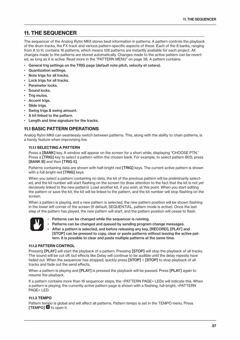
11. THE SEQUENCER
37
11. THE SEQUENCERThe sequencer of the Analog Rytm MKII stores beat information in patterns. A pattern controls the playback of the drum tracks, the FX track and various pattern-specific aspects of these. Each of the 8 banks, ranging from A to H, contains 16 patterns, which means 128 patterns are instantly available for each project. All changes made to the patterns are stored automatically. Changes made to the active pattern can be revert-ed, as long as it is active. Read more in the “PATTERN MENU” on page 38. A pattern contains:
• General trig settings on the TRIG page (default note pitch, velocity et cetera).• Quantization settings.• Note trigs for all tracks.• Lock trigs for all tracks.• Parameter locks.• Sound locks.• Trig mutes.• Accent trigs.• Slide trigs.• Swing trigs & swing amount.• A kit linked to the pattern.• Length and time signature for the tracks.
11.1 BASIC PATTERN OPERATIONSAnalog Rytm MKII can seamlessly switch between patterns. This, along with the ability to chain patterns, is a handy feature when improvising live.
11.1.1 SELECTING A PATTERNPress a [BANK] key. A window will appear on the screen for a short while, displaying “CHOOSE PTN.” Press a [TRIG] key to select a pattern within the chosen bank. For example, to select pattern B05, press [BANK B] and then [TRIG 5].
Patterns containing data are shown with half-bright red [TRIG] keys. The current active pattern is shown with a full-bright red [TRIG] keys.
When you select a pattern containing no data, the kit of the previous pattern will be preliminarily select-ed, and the kit number will start flashing on the screen (to draw attention to the fact that the kit is not yet decisively linked to the new pattern). Load another kit, if you wish, at this point. When you start editing the pattern or save the kit, the kit will be linked to the pattern, and the kit number will stop flashing on the screen.
When a pattern is playing, and a new pattern is selected, the new pattern position will be shown flashing in the lower left corner of the screen (If default, SEQUENTIAL, pattern mode is active). Once the last step of the pattern has played, the new pattern will start, and the pattern position will cease to flash.
• Patterns can be changed while the sequencer is running.• Patterns can be changed and queued by sending program change messages.• After a pattern is selected, and before releasing any key, [RECORD], [PLAY] and
[STOP] can be pressed to copy, clear or paste patterns without leaving the active pat-tern. It is possible to clear and paste multiple patterns at the same time.
11.1.2 PATTERN CONTROLPressing [PLAY] will start the playback of a pattern. Pressing [STOP] will stop the playback of all tracks. The sound will be cut off, but effects like Delay will continue to be audible until the delay repeats have faded out. When the sequencer has stopped, quickly press [STOP] + [STOP] to stop playback of all tracks and fade out the send effects.
When a pattern is playing and [PLAY] is pressed the playback will be paused. Press [PLAY] again to resume the playback.
If a pattern contains more than 16 sequencer steps, the <PATTERN PAGE> LEDs will indicate this. When a pattern is playing, the currently active pattern page is shown with a flashing, full-bright, <PATTERN PAGE> LED.
11.1.3 TEMPOPattern tempo is global and will affect all patterns. Pattern tempo is set in the TEMPO menu. Press [TEMPO] to open it.
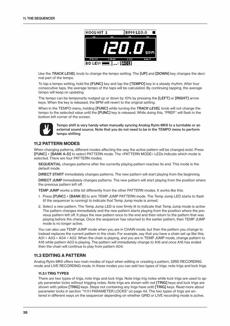
11. THE SEQUENCER
38
Use the TRACK LEVEL knob to change the tempo setting. The [UP] and [DOWN] key changes the deci-mal part of the tempo.
To tap a tempo setting, hold the [FUNC] key and tap the [TEMPO] key in a steady rhythm. After four consecutive taps, the average tempo of the taps will be calculated. By continuing tapping, the average tempo will keep on updating.
The tempo can be temporarily nudged up or down by 10% by pressing the [LEFT] or [RIGHT] arrow keys. When the key is released, the BPM will revert to the original setting.
When in the TEMPO menu, holding [FUNC] while turning the TRACK LEVEL knob will not change the tempo to the selected value until the [FUNC] key is released. While doing this, “PREP.” will flash in the bottom left corner of the screen.
Tempo shift is very handy when manually syncing Analog Rytm MKII to a turntable or an external sound source. Note that you do not need to be in the TEMPO menu to perform tempo shifting
11.2 PATTERN MODESWhen changing patterns, different modes affecting the way the active pattern will be changed exist. Press [FUNC] + [BANK A–D] to select PATTERN mode. The <PATTERN MODE> LEDs indicate which mode is selected. There are four PATTERN modes.
SEQUENTIAL changes patterns after the currently playing pattern reaches its end. This mode is the default mode.
DIRECT START immediately changes patterns. The new pattern will start playing from the beginning.
DIRECT JUMP immediately changes patterns. The new pattern will start playing from the position where the previous pattern left off.
TEMP JUMP works a little bit differently from the other PATTERN modes. It works like this:
1. Press [FUNC] + [BANK D] to arm TEMP JUMP PATTERN mode. The Temp Jump LED starts to flash (if the sequencer is running) to indicate that Temp Jump mode is armed.
2. Select a new pattern. The Temp Jump LED is now firmly lit to indicate that Temp Jump mode is active The pattern changes immediately and the new pattern starts playing from the position where the pre-vious pattern left off. It plays the new pattern once to the end and then return to the pattern that was playing before the change. Once the sequencer has returned to the earlier pattern, then TEMP JUMP mode is no longer active.
You can also use TEMP JUMP mode when you are in CHAIN mode, but then the pattern you change to instead replaces the current pattern in the chain. For example, say that you have a chain set up like this: A01 > A03 > A04 > A02. When the chain is playing, and you are in TEMP JUMP mode, change pattern to A16 while pattern A03 is playing. The pattern will immediately change to A16 and once A16 has ended then the chain will continue to play from pattern A04.
11.3 EDITING A PATTERNAnalog Rytm MKII offers two main modes of input when editing or creating a pattern, GRID RECORDING mode and LIVE RECORDING mode. In these modes you can add two types of trigs: note trigs and lock trigs.
11.3.1 TRIG TYPESThere are two types of trigs, note trigs and lock trigs. Note trigs trig notes while lock trigs are used to ap-ply parameter locks without trigging notes. Note trigs are shown with red [TRIG] keys and lock trigs are shown with yellow [TRIG] keys. Steps not containing any trigs have unlit [TRIG] keys. Read more about parameter locks in section “11.11.1 PARAMETER LOCKS” on page 44. The two types of trigs are en-tered in different ways on the sequencer depending on whether GRID or LIVE recording mode is active.
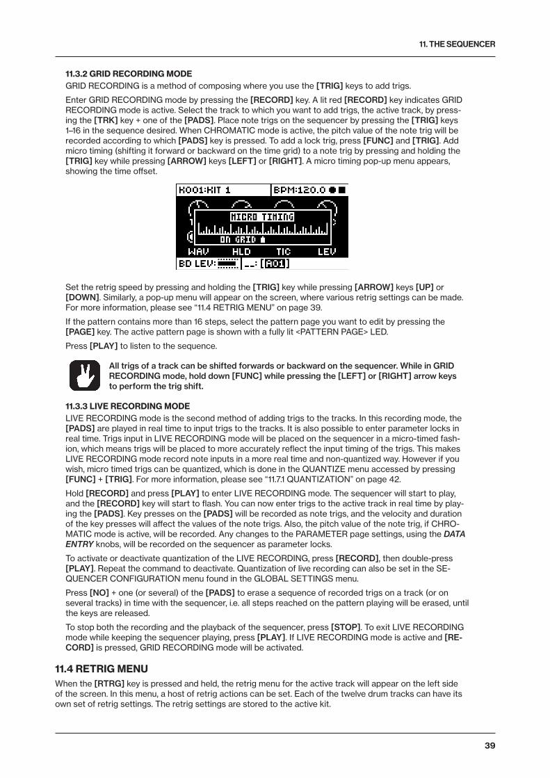
11. THE SEQUENCER
39
11.3.2 GRID RECORDING MODEGRID RECORDING is a method of composing where you use the [TRIG] keys to add trigs.
Enter GRID RECORDING mode by pressing the [RECORD] key. A lit red [RECORD] key indicates GRID RECORDING mode is active. Select the track to which you want to add trigs, the active track, by press-ing the [TRK] key + one of the [PADS]. Place note trigs on the sequencer by pressing the [TRIG] keys 1–16 in the sequence desired. When CHROMATIC mode is active, the pitch value of the note trig will be recorded according to which [PADS] key is pressed. To add a lock trig, press [FUNC] and [TRIG]. Add micro timing (shifting it forward or backward on the time grid) to a note trig by pressing and holding the [TRIG] key while pressing [ARROW] keys [LEFT] or [RIGHT]. A micro timing pop-up menu appears, showing the time offset.
Set the retrig speed by pressing and holding the [TRIG] key while pressing [ARROW] keys [UP] or [DOWN]. Similarly, a pop-up menu will appear on the screen, where various retrig settings can be made. For more information, please see “11.4 RETRIG MENU” on page 39.
If the pattern contains more than 16 steps, select the pattern page you want to edit by pressing the [PAGE] key. The active pattern page is shown with a fully lit <PATTERN PAGE> LED.
Press [PLAY] to listen to the sequence.
All trigs of a track can be shifted forwards or backward on the sequencer. While in GRID RECORDING mode, hold down [FUNC] while pressing the [LEFT] or [RIGHT] arrow keys to perform the trig shift.
11.3.3 LIVE RECORDING MODELIVE RECORDING mode is the second method of adding trigs to the tracks. In this recording mode, the [PADS] are played in real time to input trigs to the tracks. It is also possible to enter parameter locks in real time. Trigs input in LIVE RECORDING mode will be placed on the sequencer in a micro-timed fash-ion, which means trigs will be placed to more accurately reflect the input timing of the trigs. This makes LIVE RECORDING mode record note inputs in a more real time and non-quantized way. However if you wish, micro timed trigs can be quantized, which is done in the QUANTIZE menu accessed by pressing [FUNC] + [TRIG]. For more information, please see “11.7.1 QUANTIZATION” on page 42.
Hold [RECORD] and press [PLAY] to enter LIVE RECORDING mode. The sequencer will start to play, and the [RECORD] key will start to flash. You can now enter trigs to the active track in real time by play-ing the [PADS]. Key presses on the [PADS] will be recorded as note trigs, and the velocity and duration of the key presses will affect the values of the note trigs. Also, the pitch value of the note trig, if CHRO-MATIC mode is active, will be recorded. Any changes to the PARAMETER page settings, using the DATA ENTRY knobs, will be recorded on the sequencer as parameter locks.
To activate or deactivate quantization of the LIVE RECORDING, press [RECORD], then double-press [PLAY]. Repeat the command to deactivate. Quantization of live recording can also be set in the SE-QUENCER CONFIGURATION menu found in the GLOBAL SETTINGS menu.
Press [NO] + one (or several) of the [PADS] to erase a sequence of recorded trigs on a track (or on several tracks) in time with the sequencer, i.e. all steps reached on the pattern playing will be erased, until the keys are released.
To stop both the recording and the playback of the sequencer, press [STOP]. To exit LIVE RECORDING mode while keeping the sequencer playing, press [PLAY]. If LIVE RECORDING mode is active and [RE-CORD] is pressed, GRID RECORDING mode will be activated.
11.4 RETRIG MENUWhen the [RTRG] key is pressed and held, the retrig menu for the active track will appear on the left side of the screen. In this menu, a host of retrig actions can be set. Each of the twelve drum tracks can have its own set of retrig settings. The retrig settings are stored to the active kit.

11. THE SEQUENCER
40
Use the [ARROW] keys [UP] and [DOWN] to highlight one of the retrig actions (there are more than the four visible on the screen). Change values using the [ARROW] keys [LEFT] and [RIGHT]. The values can also be set using the TRACK LEVEL knob. The retrig actions available in this menu are:
RETRIG Sets the retrig rate (1/1, 1/2, 1/3, 1/4, 1/5, 1/6, 1/8, 1/10, 1/12, 1/16, 1/20, 1/24, 1/32, 1/40, 1/48, 1/64 or 1/80). 1/16 is the nominal retrig rate, one trig per step. 1/32 corresponds to two trigs per step and so on. To trig triplets, for example, set the retrig rate to 1/12 (or 1/24).
LENGTH Sets the duration of the retrig velocity curve in fractions of, or rational or integer multiples of, a step (0,125 - INF). 1/16 is the nominal length of one step. This setting affects the behavior of the velocity curve (see directly below), by defining the boundaries of its envelope.
VEL. CUR Sets the velocity curve fade out/fade in of the retrig (-128 to 127). -128 corresponds to a com-plete fade out during the set length, -64 fades out to half the velocity during the set length, 0 equals a flat velocity curve with no fade, 64 fades into half velocity during the set length and 127 fades in com-pletely to full velocity during the set length.
ALWAYS ON Sets retrig lock ON/OFF. When on, the retrig will activate whenever the pad of the active track is pressed without the need to press [RTRG] first.
Retrigs can be recorded on the sequencer in GRID RECORDING mode as well as in LIVE RECORDING mode. They are recorded as separate trigs. If the retrig speed is greater than the duration of a sequencer step, trigs are created with additional internal steps (i.e., steps with retrig enabled). Trigless trigs are insert-ed to record pad pressure changes.
Retrigs can be customized on any of the sequencer steps. Press a [TRIG] key, then press the [RTRG] key or the [ARROW] keys [UP] or [DOWN]. This will bring up a pop-up menu on the screen showing four retrig actions.
As long as the [TRIG] key is pressed, the pop-up menu will remain visible. In order to activate/deactivate the retrig, press the [RTRG] key, or turn DATA ENTRY knob A. To set the retrig rate, press the [ARROW] keys [UP] and [DOWN] or turn DATA ENTRY knob E. Change the length of the retrig velocity curve using DATA ENTRY knob D. The velocity curve of the retrig is set using DATA ENTRY knob H. The knob works in a bipolar fashion, spanning the range -128 to 127. Negative velocity values fade out the retrig to the set amount, positive values fade it in. The retrig settings in this menu can also be accessed from the RETRIG menu. However, retrig settings placed on a specific trig on the sequencer via the pop-up menu will override the general retrig settings for the active track. Read more about the functionality of retrig settings on the previous page.
11.5 TRACK MENUSettings and options for the active track are found in this menu. Open the menu by pressing [FUNC] + [CHRO]. Browse the list using the [UP]/[DOWN] arrow keys or the TRACK LEVEL knob. Select by pressing [YES]. Change the track that will be affected by pressing the [TRK] key + one of the [PADS].
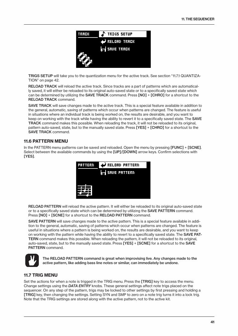
11. THE SEQUENCER
41
TRIGS SETUP will take you to the quantization menu for the active track. See section “11.7.1 QUANTIZA-TION” on page 42.
RELOAD TRACK will reload the active track. Since tracks are a part of patterns which are automatical-ly saved, it will either be reloaded to its original auto-saved state or to a specifically saved state which can be determined by utilizing the SAVE TRACK command. Press [NO] + [CHRO] for a shortcut to the RELOAD TRACK command.
SAVE TRACK will save changes made to the active track. This is a special feature available in addition to the general, automatic, saving of patterns which occur when patterns are changed. The feature is useful in situations where an individual track is being worked on, the results are desirable, and you want to keep on working with the track while having the ability to revert it to a specifically saved state. The SAVE TRACK command makes this possible. When reloading the track, it will not be reloaded to its original, pattern auto-saved, state, but to the manually saved state. Press [YES] + [CHRO] for a shortcut to the SAVE TRACK command.
11.6 PATTERN MENUIn the PATTERN menu patterns can be saved and reloaded. Open the menu by pressing [FUNC] + [SCNE]. Select between the available commands by using the [UP]/[DOWN] arrow keys. Confirm selections with [YES].
RELOAD PATTERN will reload the active pattern. It will either be reloaded to its original auto-saved state or to a specifically saved state which can be determined by utilizing the SAVE PATTERN command. Press [NO] + [SCNE] for a shortcut to the RELOAD PATTERN command.
SAVE PATTERN will save changes made to the active pattern. This is a special feature available in addi-tion to the general, automatic, saving of patterns which occur when patterns are changed. The feature is useful in situations where a pattern is being worked on, the results are desirable, and you want to keep on working with the pattern while having the ability to revert to a specifically saved state. The SAVE PAT-TERN command makes this possible. When reloading the pattern, it will not be reloaded to its original, auto-saved, state, but to the manually saved state. Press [YES] + [SCNE] for a shortcut to the SAVE PATTERN command.
The RELOAD PATTERN command is great when improvising live. Any changes made to the active pattern, like adding bass line notes or similar, can immediately be undone.
11.7 TRIG MENUSet the actions for when a note is trigged in the TRIG menu. Press the [TRIG] key to access the menu. Change settings using the DATA ENTRY knobs. These general settings affect note trigs placed on the sequencer. On any step of the pattern, trigs may be locked to other settings by first pressing and holding a [TRIG] key, then changing the settings. Setting SYN and SMP to zero on a note trig turns it into a lock trig. Note that the TRIG settings are stored along with the active pattern, not to the active kit.

11. THE SEQUENCER
42
NOT sets the pitch of the note when trigged, ranging from -24 to 24. When LIVE RECORDING and play-ing in CHROMATIC mode, the pitch of the [PADS] played will override this setting.
VEL sets the velocity at which the note trig on the sequencer is trigged, 1 to 127. This velocity is used when trigging with [FUNC] + [PADS] or with the [TRIG] keys or with the pads in FIXED VELOCITY mode and the fixed velocity set to AUTO. In LIVE RECORDING mode, the velocity at which the [PADS] are tapped will override this setting.
LEN sets the length of the note trig. Again, in LIVE RECORDING mode, the duration of pressing the [PADS] overrides this general setting.
TRC sets the Trig Condition with which a set of conditional rules can be applied to any trig, using a pa-rameter lock. For more information, please see “11.11.3 CONDITIONAL LOCKS” on page 45.
SYN controls if the synth part of the Sound will be trigged.
SMP controls if the sample part of the sound will be trigged.
ENV controls if the filter envelope will be trigged.
LFO controls if the LFO will be trigged.
11.7.1 QUANTIZATIONAccess the menu by pressing [FUNC] + [TRIG]. Navigate the menu using the [UP]/[DOWN] arrow keys or the TRACK LEVEL knob. Change settings with the [LEFT]/[RIGHT] arrow keys or any of the DATA ENTRY knobs.
GLOBAL QUANTIZE will affect all micro-timed trigs of all tracks. The higher the quantize value, the more all micro-timed trigs will be quantized. Range 0-127.
TRK QUANTIZE will affect all micro-timed trigs of the active track. The higher the quantize value, the more all micro-timed trigs will be quantized. Range 0-127.
11.8 FIXED VELOCITYPress [FIX] to enable the FIXED VELOCITY mode for the pads and set them to trig with a fixed velocity. Press [FUNC] + [FIX] to access the menu where you can adjust the fixed velocity amount.
Set the fixed velocity amount, by turning the TRACK LEVEL knob or by pressing [ARROW] keys [UP] or [DOWN]. The default setting is 100. The AUTO setting sets the fixed velocity to the default velocity as

11. THE SEQUENCER
43
specified by the VEL parameter in the TRIG menu. For more information, please see “11.7 TRIG MENU” on page 41.
11.9 CLICK TRACKThe CLICK TRACK menu controls the internal metronome of Analog Rytm MKII. Open the menu by pressing [FUNC] + [RTRG]. Use the [UP]/[DOWN] arrow keys or the TRACK LEVEL knob to scroll through the list of settings. Press [LEFT]/[RIGHT] or any of the DATA ENTRY knobs to change the highlighted setting.
ACTIVE activates/deactivates the metronome. It is also possible, outside of this menu, to keep [FUNC] + [RTRG] pressed for a second to toggle the metronome click on and off.
TIME SIG. NUM controls the note measure of the metronome time signature.
TIME SIG. DEN controls the beat measure of the metronome.
PREROLL controls for how many bars the metronome will sound before the sequencer starts playing. This setting is only relevant when LIVE RECORDING mode is initiated.
VOLUME controls the volume of the click.
11.10 SCALE MENUThe length and timing of the pattern can be changed on this screen. Two modes exist in the SCALE menu. In NORMAL mode all tracks share the same length. In ADVANCED mode each track can have different lengths. Access the SCALE SETUP menu by pressing [FUNC] + [PAGE]. Use the [LEFT] and [RIGHT] arrow keys to select between the available settings. Use the [UP] and [DOWN] keys to adjust the different settings and to select between the two modes.
11.10.1 NORMAL MODEThis is the default mode. In this mode, all tracks of the pattern share the same length and time signature. This screen will appear when the NORMAL setting is active.
The first two settings control the step length of the pattern. The leftmost number selects the number of steps in the pattern. The maximum number of steps available to the pattern is determined by the total length, set by the parameter to the right. This can be either 16, 32, 48 or 64 steps. If 17 steps or more are used in a pattern, the [PAGE] key is, while in GRID RECORDING mode, used to toggle between the different pattern pages.
The rightmost parameter controls the time signature of the pattern. It offers seven possible settings, 1/8X, 1/4X, 1/2X, 3/4X, 1X, 3/2X and 2X. A setting of 1/8X will play back the pattern at one-eighth of the set tempo. 3/4X plays the pattern back at three-quarters of the tempo. 3/2X will play back the pattern twice as fast as the 3/4X setting. 2X will make the pattern play at twice the BPM.
Trigs are automatically copied when extending the length of a pattern. If a pattern consists of for exam-ple two pages and the pattern length is increased to four pages; the two added pattern pages will be copies of the first two pattern pages.
Press the [PAGE] key for quickly changing the total length of the pattern. Press the [TRIG] keys to quickly change the number of steps of the pattern.

11. THE SEQUENCER
44
A 2X time signature setting is useful for increasing the base resolution of the step sequencer to 32nd notes. A 3/4X setting is useful when Analog Rytm MKII is playing alongside other instruments set to the same BPM, and you want Analog Rytm MKII to play triplets.
11.10.2 ADVANCED MODEIn this mode, the tracks of the pattern can be assigned individual lengths. Select ADVANCED mode by navigating to the SCALE column using the [LEFT] arrow key. Select ADVANCED by using the [DOWN] arrow key. In ADVANCED mode, two columns exist, TRACK and MASTER.
The TRACK column sets the step length of the track. It works just like setting the pattern length in NOR-MAL mode. The settings will only affect the active track. Press the [TRK] keys to select the track whose scale settings will be edited.
The MASTER column is only available in ADVANCED mode. Here the master length, the master change length and the general time signature of the pattern are set.
LEN controls the amount of steps the pattern will play before all tracks are restarted. An INF setting will make the tracks of the pattern loop infinitely, without ever being restarted. Note that this setting also affects for how long the active pattern will play before a chained pattern starts playing. This can be overridden by the CHNG parameter.
CHNG controls for how long the active pattern will play before a cued or chained pattern will begin to play. This setting is important when for example LEN is set to INF. If no CHNG setting is made, the pattern will play infinitely, and the next pattern will thus not be cued. However, if CHNG, for instance, is set to 64, the pattern will behave like a pattern consisting of 64 steps regarding cueing and chaining.
MASTER SCALE is the rightmost setting. It sets the general time signature of the pattern.
If INF is selected, the active pattern will play infinitely, making it impossible to change to another pattern (when SEQUENTIAL pattern play mode is used).
Press [FUNC] + [UP]/[DOWN] to set the MASTER LENGTH in increments of 16.
11.11 SEQUENCER FEATURES
11.11.1 PARAMETER LOCKSParameter locks enable all trigs to have their unique parameter values. The note trigs of a drum track can have, for example, different pitch, amp or filter settings. All parameters found on the PARAMETER pages are possible to parameter lock, and parameter locks can be applied to all types of tracks. Additionally, all settings on the TRIG page may be locked (see “TRIG MENU” on page 38). For an overview of all parame-ters on the PARAMETER pages, check out “APPENDIX A: DRUM TRACK PARAMETERS” on page 71.
To apply parameter locks in GRID RECORDING mode, press and hold the [TRIG] key of a trig. Adjust the parameters you want to lock using the DATA ENTRY knobs. The graphics in the screen will become in-verted for the locked parameter and the locked parameter value will be displayed. The [TRIG] key of the locked trig will begin to flash rapidly, indicating the trig now contains a parameter lock. Remove a single parameter lock by holding [TRIG] + pressing the DATA ENTRY knob of the locked parameter. By remov-ing a note trig and entering it again, all parameter locks will be erased from the trig.
In CHROMATIC mode, a note pitch parameter lock will be shown with a red color pad when you press and hold the [TRIG] key containing such a lock.
In LIVE RECORDING mode, turning a DATA ENTRY knob, or playing the [PADS] in CHROMATIC mode, will input parameter locks to the active track. Note trigs will be locked accordingly, and lock trigs contain-ing the locks will be placed on the sequencer steps not containing note trigs.
11. THE SEQUENCER
45
To remove the parameter locks of all tracks while LIVE RECORDING mode is active, press and hold [FUNC] + [NO]. Sound locks will, however, not be erased.
Press [NO] + one (or several) of the [PADS] to erase a sequence of recorded trigs on a specific track (or on several tracks) in time with the sequencer, i.e., all steps reached on the pattern playing will be erased until the keys are released. Sound locks will not be erased.
Remove specific parameter locks in real time by pressing [NO] while pressing the DATA ENTRY knob corresponding to the parameter that will be removed.
Up to 72 different parameters can be locked in a pattern. A parameter counts as one (1) locked parameter no matter how many trigs that lock it. If for example the cutoff parame-ter of the filter is locked on every sequencer step, there are still 71 other parameters that can be locked.
11.11.2 SOUND LOCKSAll drum Sounds in the Sound pool of the active project can be changed per sequencer step. Press and hold a note trig and turn the TRACK LEVEL knob. The Sound pool list will appear. Scroll the list using the TRACK LEVEL knob, select the Sound you want to assign to the note trig and then release the [TRIG] key. The [TRIG] key will start to flash. Press and hold the [TRIG] key of the note trig to show the as-signed Sound.
Remember, all Sounds may not be loaded to all tracks. If a Sound in the list is incompatible with the active track, it may not be sound locked. When browsing the Sound pool, Sounds that are incompatible with the active track are shown with a flashing (!) symbol on the screen. As are empty Sound pool slots.
The first position in the Sound pool list, titled TRACK SOUND, is the default selection. It will play the corresponding track Sound of the active kit.
11.11.3 CONDITIONAL LOCKSOn the TRIG page, there is a parameter called TRC (Trig Condition) with which a set of conditional rules can be applied to any trig, using a parameter lock. Each setting is a logical condition that determines whether a trig set on a track in the sequencer is triggered or not. If the condition is true, then the trig be-comes active and affect the track. If the condition is false, the trig is ignored. You must first place a note trig or lock trig on the sequencer step to where you want to apply a conditional lock.
The sequencer needs to be in FILL mode to activate the conditional lock called FILL. For more informa-tion, please see “11.11.4 FILL MODE” on page 46.
You can set the following trig conditions:
FILL is true (activates the trig) when FILL mode is active (see above).
FILL is true when FILL is false. A trig with this trig condition is active when you are not in FILL mode.
PRE is true if the most recently evaluated trig condition on the same track was true. (PRE and PRE conditions are ignored and not evaluated.)
PRE is true when PRE is false. A trig with this trig condition is active if the most recently evaluated trig condition on the same track was not true. (PRE and PRE conditions are ignored and not evaluated.)
Example 1: Trig 1, 50% = True > Trig 2, PRE = False > Trig 3, PRE = False > Trig 4, PRE = TrueExample 2: Trig 1, 50% = False > Trig 2, PRE = True > Trig 3, PRE = True > Trig 4, PRE = FalseNEI is true if the most recently evaluated trig condition on the neighbor track was true. (PRE and PRE conditions on the neighbor track are ignored and not evaluated.) The neighbor track is the track before the active track. For example, track 3 is the neighbor track of track 4. NEI and NEI conditional trigs on track 4 evaluate the conditional trigs placed on track 3. The NEI condition is false if no condi-tional trigs exist on the neighbor track.
NEI is true when NEI is false. A trig with this trig condition is active if the most recently evaluated trig condition on the neighbor track was not true. (PRE and PRE conditions on the neighbor track are ignored and not evaluated.)
1ST is true the first time the pattern plays (when looped).
1ST is true when 1ST is false. A trig with this trig condition is always active apart from the first time the pattern plays (when looped).
X% is a probability condition. There is an X% chance that the trig will be active.

11. THE SEQUENCER
46
A:B A sets how many times the pattern plays before the trig condition is true. B sets how many times the pattern plays before the count is reset and starts over again. This cycle then repeats until you stop the sequencer.
For example: With the setting 1:2, the trig condition is true the first time the pattern plays and then the third, the fifth, and so on. With the setting 2:2, the trig condition is true the second time the pattern plays and then the fourth, the sixth, and so on. With the setting 2:4, the trig condition is true the second time the pattern plays and then the sixth, the tenth, and so on. With the setting 4:7 the trig condition is true the fourth time the pattern plays and then the eleventh, the eighteenth, and so on.
• Conditional parameter locks are a great way to add variety to a pattern. To set up a grid of mutually exclusive or conclusive note trigs across any of the synth tracks, and throwing some probability locks in there as well (perhaps, in turn, also sporting an array of logically conditioned trigs) is a neat way to make the most minimal of compositions come alive with randomness.
• Note that random or arbitrary variety is not the only way of using conditional trigs. They may also be used, for example, to have two different melodic or percussive sequences on the same track, one of which is activated only when FILL mode is active.
11.11.4 FILL MODEFILL mode can be used to create a temporary variation, such as a drum fill, in your pattern.
Press [FUNC] + [FILL] to cue FILL mode for one pattern cycle. [FILL] starts to flash to indicate that FILL mode is cued. FILL mode will become active ([FILL] shines with a steady light) when the pattern loops, and remain active until the pattern loops again. You can also activate FILL mode at any time, and for any duration, by pressing and holding the [FILL] key when the pattern is playing (GRID RECORDING mode cannot be active). The FILL mode is active for as long as the key is held.
11.11.5 TRIG MUTEThe TRIG MUTE screen allows you to add mute masks on a sequencer pattern. Each track can have its own trig mute trigs. Open the menu by pressing [FUNC] + [BANK E].
Enter trig mute trigs by pressing the [TRIG] keys. While on the TRIG MUTE screen, the trigs entered will mute any trigs placed on the active track, given the trigs are located on the same sequencer steps. If you wish to edit the step property on all tracks simultaneously, not just the active track, press and hold [FUNC] key and then enter the trigs. The steps containing note trigs will be shown with dimly lit [TRIG] keys.
• Trig mutes can be quickly added to note trigs or lock trigs. Keep the note trig or lock trig pressed and press [BANK E]. A trig mute trig will automatically be placed on the same sequencer step as the note trig/lock trig.
• Press a note trig/lock trig to quickly see if a trig mute trig is placed on the same se-quencer step as the trig. If that is the case, the [BANK E] key will light up.
• Trig mutes are good for experimenting with the feel of tracks when playing live. The last eight steps of a bass line track could, for example, be muted to build suspense.
11.11.6 ACCENTAdding accent trigs is useful for quickly changing the velocity for chosen steps of a track. Accent level is a destination for modulation, which means it can be affected by, for example, LFOs. Open the ACCENT menu by pressing [FUNC] + [BANK F].

11. THE SEQUENCER
47
Select the track that will be affected by pressing the corresponding [TRK] key. Select the accent value by turning the TRACK LEVEL knob. The higher the value, the more accentuation will be added to accent trigs.
While the ACCENT menu is open, the sequencer will display accent trigs. Place or remove accent trigs by pressing the [TRIG] keys. If you wish to edit the step property on all tracks simultaneously, not just the active track, press and hold [FUNC] key and then enter the trigs. If an accent trig is placed on the same sequencer step as a note trig, the note trig will be accentuated.
• A note trig can be quickly accented. Keep the note trig pressed and press [BANK F]. An accent trig will automatically be placed on the same sequencer step as the note trig.
• Press a note trig/lock trig to quickly see if an accent trig is placed on the same se-quencer step as the trig. If that is the case, the [BANK F] key will light up.
11.11.7 SWINGAdjust the swing setting of the pattern, to employ a propulsive, rhythmic groove. Access this menu by pressing [FUNC] + [BANK G].
Set the SWING ratio to 51-80%, by turning the TRACK LEVEL knob or by pressing [ARROW] keys [UP] or [DOWN]. The default setting is equal spacing, 50%. Customize the swing pattern, shown by lit [TRIG] keys, using the [TRIG] keys.
11.11.8 PARAMETER SLIDEThe PARAMETER SLIDE menu makes it possible for the parameter values of two separate note trigs or lock trigs of a track to slide between each other. Open the menu by pressing [FUNC] + [BANK H]. When this menu is active, and [TRIG] keys are pressed, slide trigs will be placed on the sequencer. If you wish to edit the step property on all tracks simultaneously, not just the active track, press and hold [FUNC] key and then enter the trigs.
For a parameter value to slide between two trigs, it needs to be locked on one of the trigs. A locked pa-rameter value will slide to the unlocked value and vice versa. To make the parameter value slide, place a slide trig on the same sequencer step as the trig whose parameters you want to slide. The speed of the slide is relative to the current tempo, and the slide is completed when the next trig is reached. Several parameter values can slide at the same time.

11. THE SEQUENCER
48
• Parameter slides can be quickly added to note trigs or lock trigs. Keep the note trig or lock trig pressed and press [BANK H]. A parameter slide trig will automatically be placed on the same sequencer step as the note trig/lock trig.
• Press a note trig/lock trig to quickly see if a parameter slide trig is placed on the same sequencer step as the trig. If that is the case, the [BANK H] key will light up.
11.11.9 COPY, PASTE, AND CLEAR OPERATIONSPatterns, track pages, tracks, and trigs can be copied, pasted and cleared.
The active pattern can be copied to either another location in the same bank or to a location in anoth-er bank. To perform a pattern copy operation, GRID RECORDING mode must be inactivated. Copy the pattern by pressing [FUNC] + [RECORD]. Select another pattern and paste the copied pattern to this lo-cation by pressing [FUNC] + [STOP]. The operation can be undone by pressing [FUNC] + [STOP] again. Clear a pattern by pressing [FUNC] + [PLAY]. Undo the operation by repeating the key presses.
After selecting a pattern, and before releasing any key, [RECORD], [PLAY] and [STOP] can be pressed to copy, clear or paste patterns.
Individual sequencer tracks can be copied, pasted and cleared in the same way as patterns. To do so, GRID RECORDING mode needs to be active.
A single track page may also be copied, pasted and cleared. It is similar to copying/pasting/clearing a track, but will only affect the active track page. GRID RECORDING mode needs to be active. Select the track page of choice by pressing the [PAGE] key. Copy by pressing [PAGE] + [RECORD]. Select a new track page and press [PAGE] + [STOP] to paste. Undo by pressing [PAGE] + [STOP] again. Press [PAGE] + [PLAY] to clear the active track page. Undo the operation by repeating the key presses.
Trigs, complete with all parameter lock settings, can be copied, pasted and cleared as well. GRID RE-CORDING mode needs to be active to access this functionality. Press and hold a trig and press [RE-CORD] to perform the copy operation. Paste by holding another [TRIG] key and pressing [STOP]. It is also possible to copy more than one trig. Hold several trigs and press [RECORD]. The trig first pressed will act as the starting point. When pasting, the other copied trigs will be placed in relation to this trig. Paste the copied sequence of trigs by holding another [TRIG] key and pressing [STOP]. Clear trig locks by holding one or more trigs and press [PLAY].
11.11.10 QUICK SAVE AND RELOAD COMMANDSKits, Sounds, tracks, patterns, and songs can instantly be saved and reloaded. When reloading, settings will revert to their saved state.
• To quick save a kit, press [YES] + [PLAY MODE]. This command is the same as the SAVE KIT com-mand found in the KIT menu, see “10.2 KIT MENU” on page 26.
• To quick save the track Sound of the active track, press [YES] + [MUTE]. This command is the same as the STORE TRACK SOUND command found in the SOUND MANAGER menu, see “10.5.2 SOUND MANAGER” on page 32.
• To quick save a track, press [YES] + [CHRO]. The operation is the same as the SAVE TRACK com-mand, see “11.5 TRACK MENU” on page 40.
• To quick save the active pattern, press [YES] + [SCNE]. The operation is the same as the SAVE PAT-TERN command, see “11.6 PATTERN MENU” on page 41. This is useful to create a restore point before you start a session of live tweaking that might not turn out the way you want.
• To quick save a song, press [YES] + [PERF]. The command is the same as the SAVE command found in the SONG menu, see “12.2.4 SONG MENU” on page 51.
• To quick reload a kit, press [NO] + [PLAY MODE]. This command is the same as the RELOAD KIT command found in the KIT menu, see “10.2 KIT MENU” on page 26. This is useful in a live situation after a kit has been subject to improvised changes.
• To quick reload the track Sound of the active track, press [NO] + [MUTE]. This is the same as kit reload, but only on the active track (not all tracks).
• To quick reload a track, press [NO] + [CHRO]. The operation is the same as the RELOAD TRACK command, see “11.5 TRACK MENU” on page 40.
• To quick reload the active pattern, press [NO] + [SCNE]. The operation is the same as the RELOAD PATTERN command, see “11.6 PATTERN MENU” on page 41. Only useful until another pattern is selected, as an undo operation after live changes.
• To quick reload a song, press [NO] + [PERF]. The command is the same as the RELOAD command found in the SONG menu, see “12.2.4 SONG MENU” on page 51.

12. CHAINS AND SONGS
49
12. CHAINS AND SONGSChains are sequences that consist of one or more patterns. Chains are used to form songs.
256 pattern entries are available to the 64 chains. For example, one chain can consist of 256 patterns or two chains can consist of 128 patterns each.
One song is always active and worked on. Songs contain two main forms of entries, song rows, and a scratch pad row. The active song row is visible in the bottom left part of the LCD. If a scratch pad row is active, the graphics will show “_ _:”. The scratch pad row is by default placed after all song rows.
Each song row contains a chain. These entries are saved together with the song. The scratch pad row also contains a chain or a pattern and is also saved as part of the song. The purpose of the scratch pad row is to enable experimentation with chains and patterns without affecting already programmed song rows.
12.1 CHAINSIf the active song row or scratch pad row contains a chain, all patterns of the chain will be played when activating the CHAIN mode by pressing [CHAIN MODE] . When deactivating the mode, and SONG mode is not active, the currently active pattern will be played over and over. The active pattern, and any other pat-terns in the chain are visible at the bottom of the screen. The active pattern is shown with inverted color.
There are two ways to create chains: Detailed chain mode and Quick chain mode.
12.1.1 DETAILED MODECHAIN mode must be active if you want to create chains in detailed mode. Create chains in detailed mode by pressing [CHAIN MODE] + [LEFT]/[RIGHT] to move the chain cursor. It can either be placed before a pattern, on a pattern or after a pattern. If the cursor is placed before a pattern and a new pat-tern is selected by pressing [BANK] + [TRIG], the selected pattern will be inserted before the pattern located after the cursor. If the cursor is highlighting a pattern and a new pattern is selected, the high-lighted pattern will be replaced. When activating CHAIN mode, the patterns in the chain will be played in sequence. The chain will be looped once the final pattern of the chain has played.
12.1.2 QUICK MODETo create chains in quick mode, press [BANK] and then press the [TRIG] key for the pattern you want the chain to start with. As long as you keep the first [TRIG] key pressed, subsequent [TRIG] keys pressed will add patterns to the chain. In quick mode, it is only possible to chain patterns from the same bank. Please note that the previous chain will be erased when using quick mode. PATTERN mode must be set to SEQUENTIAL if you wish to create chains in quick mode.
Pressing [CHAIN MODE] + [NO] will, depending on the location of the chain cursor, either erase the pattern located before the cursor or the one highlighted by it.
Pressing [FUNC] + [CHAIN MODE] will create a new, blank, scratch pad row. The scratch pad row will be placed at the very bottom of the song row list (which can be seen when opening the SONG EDIT menu). The content of the previous scratch pad row will be added as a new song row following the last song row. See SONG EDIT MENU on how to relocate song rows (including the scratch pad row) within the song.
CHAIN mode is ideal when improvising live. When CHAIN mode is deactivated and only the currently active pattern is looping, create a chain and then activate CHAIN mode. At any time, exit CHAIN mode to loop one pattern only. Add and remove patterns to create a completely new chain and activate CHAIN mode again. By creating new chains through pressing [FUNC] + [CHAIN MODE], improvised songs can quickly be created.
12.2 SONGSSongs are essentially patterns and chains structured to form a longer sequence. To enter SONG mode, press the [SONG MODE] key. The [SONG MODE] key will light up, indicating SONG mode is active. The active song will start to play, row by row. If the active song row is the scratch pad row (in its bottom-of-the-stack default position) it will play through its chain of patterns once, then stop. If the scratch pad row has been moved within the song, it will play the following song row. The song row playing is shown in the lower left corner of the screen.
12.2.1 SONG EDIT MENUSongs are created in the SONG EDIT menu, which is accessed by pressing [FUNC] + [SONG MODE].

12. CHAINS AND SONGS
50
Songs are played row by row, starting from the top and moving towards the bottom. If a song row con-tains a chain, all patterns in the chain will play before the song play position moves to the next row. The song play position is shown with inverted pattern number graphics. In the top right corner of the screen, the BPM and the amount of played bars and beats is shown.
To navigate between song rows as well as patterns assigned to the song rows, use the [ARROW] keys. When the song cursor highlights a pattern position, the pattern number becomes enclosed by a square. When the song cursor is placed before or after a pattern, it will form a thin line.
To start playing a Song from the beginning, double-press [STOP]. The song play position will automat-ically be moved to the first pattern of the first song row. Songs can, however, start playing from any pattern position. Highlight a pattern position by moving the song cursor using the [ARROW] keys. Press [YES] to select this position. The graphics will become inverted, indicating this is the song play position. Press [PLAY] to start playing the Song from this position.
Copy, paste, and clear commands can be executed on the song rows.
12.2.2 ADDING SONG ROWS AND ASSIGNING PATTERNS AND CHAINSPress [FUNC] + [YES] to add a song row. The new song row will be inserted below the row on which the cursor is, and the pattern A01 will automatically be assigned to the new row. To assign another pattern to the song row, use the [ARROW] keys to move the song cursor so the pattern assigned to the row becomes highlighted and then press a [BANK] key + a [TRIG] key. In general, the pattern assigning pro-cedure is the same as when selecting a pattern, covered in the section “11.1.1 SELECTING A PATTERN” on page 37.
To add a chain to a song row, select a song row and press the [RIGHT] arrow key. The song cursor will move from the pattern position and form a thin, standing line. Press a [BANK] key + a [TRIG] key to select the pattern that will be added to the chain.
Remove a pattern in a chain by highlighting it with the song cursor and pressing [FUNC] + [NO].
If a song row contains a chain, individual patterns can be rearranged in the chain. Select the pattern by highlighting it with the song cursor and press [FUNC] + [LEFT]/[RIGHT].
Move a song row up or down in the song by moving the song cursor to the song row and pressing [FUNC] + [UP]/[DOWN].
Erase a song row, one pattern at a time, by pressing [FUNC] + [NO] repeatedly.
12.2.3 ADDING REPEATS AND MUTESVarious extra information can be entered for song rows and the pattern or patterns assigned to the song rows.
Repeat a song row a chosen number of times by moving to the leftmost position of the song row with the cursor. Turn DATA ENTRY knob A to select how many times the song row will be repeated.
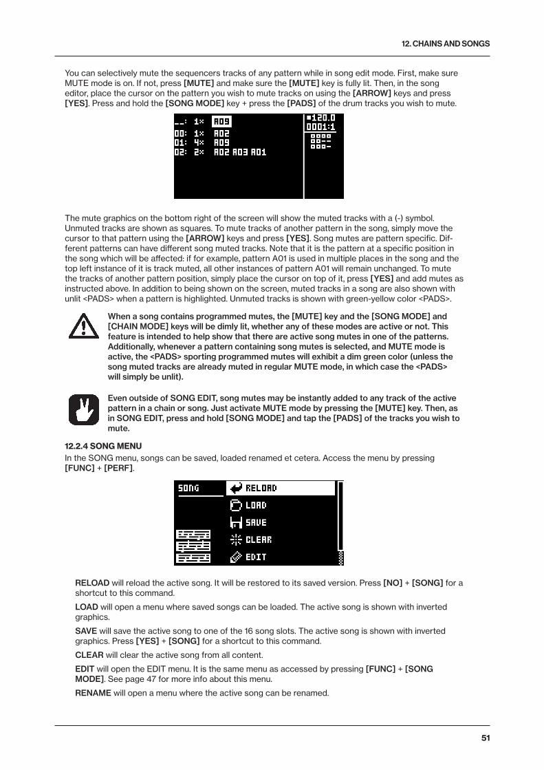
12. CHAINS AND SONGS
51
You can selectively mute the sequencers tracks of any pattern while in song edit mode. First, make sure MUTE mode is on. If not, press [MUTE] and make sure the [MUTE] key is fully lit. Then, in the song editor, place the cursor on the pattern you wish to mute tracks on using the [ARROW] keys and press [YES]. Press and hold the [SONG MODE] key + press the [PADS] of the drum tracks you wish to mute.
The mute graphics on the bottom right of the screen will show the muted tracks with a (-) symbol. Unmuted tracks are shown as squares. To mute tracks of another pattern in the song, simply move the cursor to that pattern using the [ARROW] keys and press [YES]. Song mutes are pattern specific. Dif-ferent patterns can have different song muted tracks. Note that it is the pattern at a specific position in the song which will be affected: if for example, pattern A01 is used in multiple places in the song and the top left instance of it is track muted, all other instances of pattern A01 will remain unchanged. To mute the tracks of another pattern position, simply place the cursor on top of it, press [YES] and add mutes as instructed above. In addition to being shown on the screen, muted tracks in a song are also shown with unlit <PADS> when a pattern is highlighted. Unmuted tracks is shown with green-yellow color <PADS>.
When a song contains programmed mutes, the [MUTE] key and the [SONG MODE] and [CHAIN MODE] keys will be dimly lit, whether any of these modes are active or not. This feature is intended to help show that there are active song mutes in one of the patterns. Additionally, whenever a pattern containing song mutes is selected, and MUTE mode is active, the <PADS> sporting programmed mutes will exhibit a dim green color (unless the song muted tracks are already muted in regular MUTE mode, in which case the <PADS> will simply be unlit).
Even outside of SONG EDIT, song mutes may be instantly added to any track of the active pattern in a chain or song. Just activate MUTE mode by pressing the [MUTE] key. Then, as in SONG EDIT, press and hold [SONG MODE] and tap the [PADS] of the tracks you wish to mute.
12.2.4 SONG MENUIn the SONG menu, songs can be saved, loaded renamed et cetera. Access the menu by pressing [FUNC] + [PERF].
RELOAD will reload the active song. It will be restored to its saved version. Press [NO] + [SONG] for a shortcut to this command.
LOAD will open a menu where saved songs can be loaded. The active song is shown with inverted graphics.
SAVE will save the active song to one of the 16 song slots. The active song is shown with inverted graphics. Press [YES] + [SONG] for a shortcut to this command.
CLEAR will clear the active song from all content.
EDIT will open the EDIT menu. It is the same menu as accessed by pressing [FUNC] + [SONG MODE]. See page 47 for more info about this menu.
RENAME will open a menu where the active song can be renamed.

13. SAMPLING
52
13. SAMPLINGAnalog Rytm MKII is also a competent and accessible sampler. It can sample audio from external sources via the AUDIO IN inputs, and it can also sample audio internally from the Analog Rytm MKII itself. The max-imum sampling time is 33 seconds.
13.1 SAMPLING MENUThe SAMPLING menu offers settings that control the different aspects of sampling.
Press [SAMPLING] to access this menu. Use the DATA ENTRY knobs to change the parameters.
13.1.1 RECPress [FUNC] + [YES] to start sampling. Press [YES] to stop sampling.
13.1.2 ARMPress [YES] to arm the sampler. The sampler is now in arm mode and it will start sampling when the incoming audio exceeds the threshold level. See below. (Press [SAMPLING] + [NO] to cancel.)
13.1.3 THRIf you have selected to arm the sampler, the sampling begins when the incoming audio signal exceeds the threshold setting. Set the threshold high enough so that it is not triggered by background noise, but low enough that you capture all of the signal.
13.1.4 SRCSource selects between different audio sources to sample from.
• AUD L+R sets the input source to sample external audio through the AUDIO IN L+R inputs. The audio is summed together to mono.
• AUD L sets the input source to AUDIO IN L.
• AUD R sets the input source to AUDIO IN R.
• BD, SD, RS/CP, BT, LT, MT/HT, CH/OH, CY/CB sets the input source to the internal audio from the separate drum tracks.
• MAIN sets the input source to the internal MAIN L+R channels. The audio is summed together to mono.
13.1.5 MONSelects the option to monitor the incoming audio through the Analog Rytm MKII or not.
Please note that in most cases you always monitor the internal audio and this parameter is then not available when you chose the separate drum tracks or MAIN as input sources. How-ever, if your sample source is an individual track that you have routed not to send audio to the MAIN OUT, then the MON parameter is available. For more information, please see “14.6 TRACK ROUTING GLOBAL” on page 59.
13.2 SAMPLING WITH THE ANALOG RYTM MKII1. If you use an external audio source, connect it to the Analog Rytm MKII.2. Press [SAMPLING] to access the SAMPLING menu and then use DATA ENTRY knob G to set
SOURCE to your preferred audio input source. 3. Keep an eye on the audio input meter and play the audio source and make sure that the volume of the
audio source is as strong as possible, but without clipping or distorting. If needed, set MON to YES to monitor the incoming audio through the Analog Rytm MKII.

13. SAMPLING
53
4. Again, with an eye on the audio input meter, use DATA ENTRY knob F to set THR just above the indi-cated background noise of the audio source (when it is not playing).
5. Press [YES] to arm the sampler and then play the sound source. When the incoming audio signal exceeds the set threshold level, sampling will start.
6. Press [YES] when you want to stop sampling. The Analog Rytm MKII then automatically normalizes the sample.
7. Use the DATA ENTRY knobs A and C to set the parameters TRIM START and TRIM END to trim the sample to the desired length. You can use the DATA ENTRY knobs B and D to zoom in and out to make it easier to see where to trim the sample. Press [FUNC] + [YES] to preview the sample. Press [YES] to trim the sample. After you have trimmed the sample, you can press [NO] to untrim the sample if you are not happy with the result.
8. Press [YES] to save the sample.9. Name the sample and press [YES] again to confirm the save.10. Press one of the [PADS] to select the track to where you want to assign the sample. Press [NO] if you
don’t want to assign the sample to a track.
Press [FUNC] + [NO] if you wish to discard the sample.
Press [NO] to close the SAMPLING menu.
13.3 DIRECT SAMPLINGYou can also perform sampling without using the SAMPLING menu. This is achieved by a set of key press combinations. The sampler will use the SRC and THR settings that were last used.
1. Press [SAMPLING] + [YES] to arm the sampler. The [SAMPLING] key turns yellow. You can also start direct sampling without arming the sampler first. Press [FUNC] + [SAMPLING] to manually start sampling.
2. When the incoming audio signal exceeds the set threshold level (or you manually start direct sam-pling), the sampling starts, and the [SAMPLING] key turns red.
3. Press [FUNC] + [SAMPLING] to stop sampling. The [SAMPLING] key first turns dark red while nor-malizing the sample, then green when it is done.
Press [SAMPLING] + [NO] to cancel at any stage of the Direct Sampling process.

14. GLOBAL SETTINGS MENU
54
14. GLOBAL SETTINGS MENU The GLOBAL SETTINGS menu offers settings that affect Analog Rytm MKII on a global level. Global sequencer, MIDI, and track routing settings are made here. Up to four Global slots are available, each with its individual settings.
Access the menu by pressing [GLOBAL SETTINGS]. Scroll the list by using [UP]/[DOWN] or the TRACK LEVEL knob. Open a highlighted menu by pressing [YES].
14.1 PROJECTThis is where you manage the projects. This menu is described in the section “9. PROJECTS” on page 24.
14.2 SAMPLESManage your samples here. On the main screen, seen below, you can access one of three main directories, FACTORY, INCOMING, or recorded. In the FACTORY directory, several preset samples can be found in one of the ten subdirectories. The INCOMING directory, is the default destination for samples sent to the Ana-log Rytm MKII +Drive storage via the C6 utility software. The RECORDED directory is the default destina-tion for samples that is sampled with the Analog Rytm MKII. Press [YES] to open a directory.
To open a subdirectory, simply highlight it using the [ARROW] keys and press [YES]. To exit a directory, select the item labeled “..” at the very top of the screen and press [YES]. Do this repeatedly to return to the top of the directory hierarchy. To discern directories from sample files, all directories, including the directory exit row, “..”, are labeled with a (D) at the end of the row. When browsing a directory in the +Drive, a sample assigned to one of the 127 sample slots of the active project has its slot number shown after its name, as seen below.
14.2.1 LOADING, UNLOADING OR REPLACING A SAMPLEThe following is an example of how to load one or several of the preset samples to the active project. First, open the FACTORY directory. Second, open the PERCUSSION directory. Highlight the first sample, “Agogo High” and press [YES] to tick it. Browse the list and tick a few other samples. Any sample may be previewed (played back by the voice of the active track) by first highlighting it and then pressing [FUNC] + [YES]. Circa, ten seconds of the sample will be previewed. Third, press the [RIGHT] arrow key. A menu will appear on the right side of the screen.
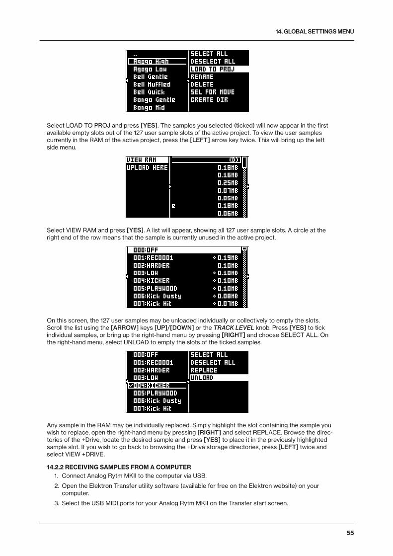
14. GLOBAL SETTINGS MENU
55
Select LOAD TO PROJ and press [YES]. The samples you selected (ticked) will now appear in the first available empty slots out of the 127 user sample slots of the active project. To view the user samples currently in the RAM of the active project, press the [LEFT] arrow key twice. This will bring up the left side menu.
Select VIEW RAM and press [YES]. A list will appear, showing all 127 user sample slots. A circle at the right end of the row means that the sample is currently unused in the active project.
On this screen, the 127 user samples may be unloaded individually or collectively to empty the slots. Scroll the list using the [ARROW] keys [UP]/[DOWN] or the TRACK LEVEL knob. Press [YES] to tick individual samples, or bring up the right-hand menu by pressing [RIGHT] and choose SELECT ALL. On the right-hand menu, select UNLOAD to empty the slots of the ticked samples.
Any sample in the RAM may be individually replaced. Simply highlight the slot containing the sample you wish to replace, open the right-hand menu by pressing [RIGHT] and select REPLACE. Browse the direc-tories of the +Drive, locate the desired sample and press [YES] to place it in the previously highlighted sample slot. If you wish to go back to browsing the +Drive storage directories, press [LEFT] twice and select VIEW +DRIVE.
14.2.2 RECEIVING SAMPLES FROM A COMPUTER1. Connect Analog Rytm MKII to the computer via USB.
2. Open the Elektron Transfer utility software (available for free on the Elektron website) on your computer.
3. Select the USB MIDI ports for your Analog Rytm MKII on the Transfer start screen.
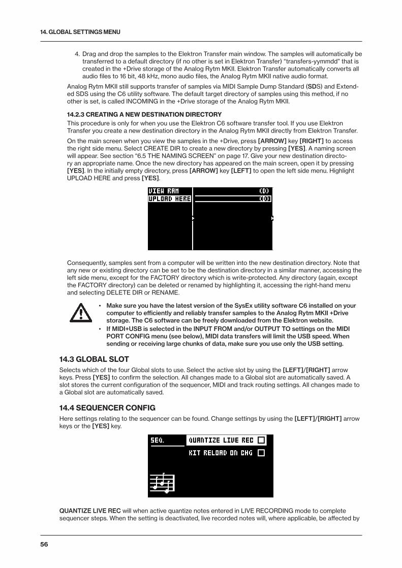
14. GLOBAL SETTINGS MENU
56
4. Drag and drop the samples to the Elektron Transfer main window. The samples will automatically be transferred to a default directory (if no other is set in Elektron Transfer) “transfers-yymmdd” that is created in the +Drive storage of the Analog Rytm MKII. Elektron Transfer automatically converts all audio files to 16 bit, 48 kHz, mono audio files, the Analog Rytm MKII native audio format.
Analog Rytm MKII still supports transfer of samples via MIDI Sample Dump Standard (SDS) and Extend-ed SDS using the C6 utility software. The default target directory of samples using this method, if no other is set, is called INCOMING in the +Drive storage of the Analog Rytm MKII.
14.2.3 CREATING A NEW DESTINATION DIRECTORYThis procedure is only for when you use the Elektron C6 software transfer tool. If you use Elektron Transfer you create a new destination directory in the Analog Rytm MKII directly from Elektron Transfer.
On the main screen when you view the samples in the +Drive, press [ARROW] key [RIGHT] to access the right side menu. Select CREATE DIR to create a new directory by pressing [YES]. A naming screen will appear. See section “6.5 THE NAMING SCREEN” on page 17. Give your new destination directo-ry an appropriate name. Once the new directory has appeared on the main screen, open it by pressing [YES]. In the initially empty directory, press [ARROW] key [LEFT] to open the left side menu. Highlight UPLOAD HERE and press [YES].
Consequently, samples sent from a computer will be written into the new destination directory. Note that any new or existing directory can be set to be the destination directory in a similar manner, accessing the left side menu, except for the FACTORY directory which is write-protected. Any directory (again, except the FACTORY directory) can be deleted or renamed by highlighting it, accessing the right-hand menu and selecting DELETE DIR or RENAME.
• Make sure you have the latest version of the SysEx utility software C6 installed on your computer to efficiently and reliably transfer samples to the Analog Rytm MKII +Drive storage. The C6 software can be freely downloaded from the Elektron website.
• If MIDI+USB is selected in the INPUT FROM and/or OUTPUT TO settings on the MIDI PORT CONFIG menu (see below), MIDI data transfers will limit the USB speed. When sending or receiving large chunks of data, make sure you use only the USB setting.
14.3 GLOBAL SLOTSelects which of the four Global slots to use. Select the active slot by using the [LEFT]/[RIGHT] arrow keys. Press [YES] to confirm the selection. All changes made to a Global slot are automatically saved. A slot stores the current configuration of the sequencer, MIDI and track routing settings. All changes made to a Global slot are automatically saved.
14.4 SEQUENCER CONFIGHere settings relating to the sequencer can be found. Change settings by using the [LEFT]/[RIGHT] arrow keys or the [YES] key.
QUANTIZE LIVE REC will when active quantize notes entered in LIVE RECORDING mode to complete sequencer steps. When the setting is deactivated, live recorded notes will, where applicable, be affected by
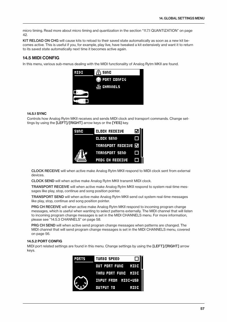
14. GLOBAL SETTINGS MENU
57
micro timing. Read more about micro timing and quantization in the section “11.7.1 QUANTIZATION” on page 42.
KIT RELOAD ON CHG will cause kits to reload to their saved state automatically as soon as a new kit be-comes active. This is useful if you, for example, play live, have tweaked a kit extensively and want it to return to its saved state automatically next time it becomes active again.
14.5 MIDI CONFIGIn this menu, various sub-menus dealing with the MIDI functionality of Analog Rytm MKII are found.
14.5.1 SYNCControls how Analog Rytm MKII receives and sends MIDI clock and transport commands. Change set-tings by using the [LEFT]/[RIGHT] arrow keys or the [YES] key.
CLOCK RECEIVE will when active make Analog Rytm MKII respond to MIDI clock sent from external devices.
CLOCK SEND will when active make Analog Rytm MKII transmit MIDI clock.
TRANSPORT RECEIVE will when active make Analog Rytm MKII respond to system real-time mes-sages like play, stop, continue and song position pointer.
TRANSPORT SEND will when active make Analog Rytm MKII send out system real-time messages like play, stop, continue and song position pointer.
PRG CH RECEIVE will when active make Analog Rytm MKII respond to incoming program change messages, which is useful when wanting to select patterns externally. The MIDI channel that will listen to incoming program change messages is set in the MIDI CHANNELS menu. For more information, please see “14.5.3 CHANNELS” on page 58.
PRG CH SEND will when active send program change messages when patterns are changed. The MIDI channel that will send program change messages is set in the MIDI CHANNELS menu, covered on page 56.
14.5.2 PORT CONFIGMIDI port related settings are found in this menu. Change settings by using the [LEFT]/[RIGHT] arrow keys.

14. GLOBAL SETTINGS MENU
58
TURBO SPEED press [YES] to start the turbo speed negotiation. Speed is chosen automatically. Please note that you must use a MIDI interface that supports the Turbo-MIDI protocol.
OUT PORT FUNCTIONALITY selects what type of signal the MIDI OUT port will send.
• MIDI makes it possible for the port to send out MIDI data.
• DIN 24 will make the port send DIN 24 sync pulses. No MIDI data is sent on the port when this option is selected.
• DIN 48 will make the port send DIN 48 sync pulses. No MIDI data is sent on the port when this option is selected.
THRU PORT FUNCTIONALITY selects what type of signal the MIDI THRU port will send. The settings are the same as for OUT PORT FUNCTIONALITY.
INPUT FROM selects the source Analog Rytm MKII will receive MIDI data from.
• DISABLED will make Analog Rytm MKII disregard any incoming MIDI data.
• MIDI will make Analog Rytm MKII listen only to MIDI data sent to the MIDI IN port.
• USB will make Analog Rytm MKII listen only to MIDI data sent to the USB port.
• MIDI+USB will make Analog Rytm MKII listen to MIDI data sent to both the MIDI IN and USB ports.
OUTPUT TO selects the destination to which Analog Rytm MKII will send MIDI data.
• DISABLED will stop Analog Rytm MKII from sending out any MIDI data.
• MIDI will make Analog Rytm MKII send MIDI data to the MIDI OUT port only.
• USB will make Analog Rytm MKII send MIDI data to the USB port only.
• MIDI+USB will make Analog Rytm MKII send MIDI data to both the MIDI OUT and USB ports.
• If MIDI+USB is selected in the INPUT FROM and/or OUTPUT TO settings, MIDI data transfers will limit the USB speed. When sending or receiving large chunks of data, make sure you use only the USB setting.
OUTPUT CH selects whether the [PADS] and the knobs will send data on the auto channel or the track channel.
PARAM OUTPUT selects what type of MIDI messages the DATA ENTRY knobs will send. For information about which CC/NRPN parameters that will be sent, please see “APPENDIX C: MIDI” on page 79.
• NRPN will make the knobs send out NRPN MIDI messages.
• CC will make the knobs send out CC MIDI messages.
ENCODER DEST controls whether the DATA ENTRY and TRACK LEVEL knobs will send MIDI data or not. When set to INT, no MIDI data will be sent. When set to INT + EXT, MIDI will be sent internally as well as externally.
PAD DEST controls whether the [PADS] will send MIDI data or not. When set to INT, no MIDI data will be sent. When set to INT + EXT, MIDI will be sent internally as well as externally. When set to EXT, MIDI will only be sent externally.
PRESSURE DEST controls whether varying pressure applied to the [PADS] will send MIDI data or not. When set to INT, no MIDI data will be sent. When set to INT + EXT, MIDI will be sent internally as well as externally. When set to EXT, MIDI will only be sent externally.
MUTE DEST controls whether activating/deactivating mutes will send MIDI data or not. When set to INT, no MIDI data will be sent. When set to INT + EXT, MIDI will be sent internally as well as externally. When set to EXT, MIDI will only be sent externally.
RECEIVE NOTES will when active, make it possible to play Analog Rytm MKII using an external MIDI keyboard.
RECEIVE CC/NRPN will when active make it possible to control Analog Rytm MKII parameters from an external MIDI device sending CC/NRPN data.
14.5.3 CHANNELSThis menu handles the MIDI channel configuration.
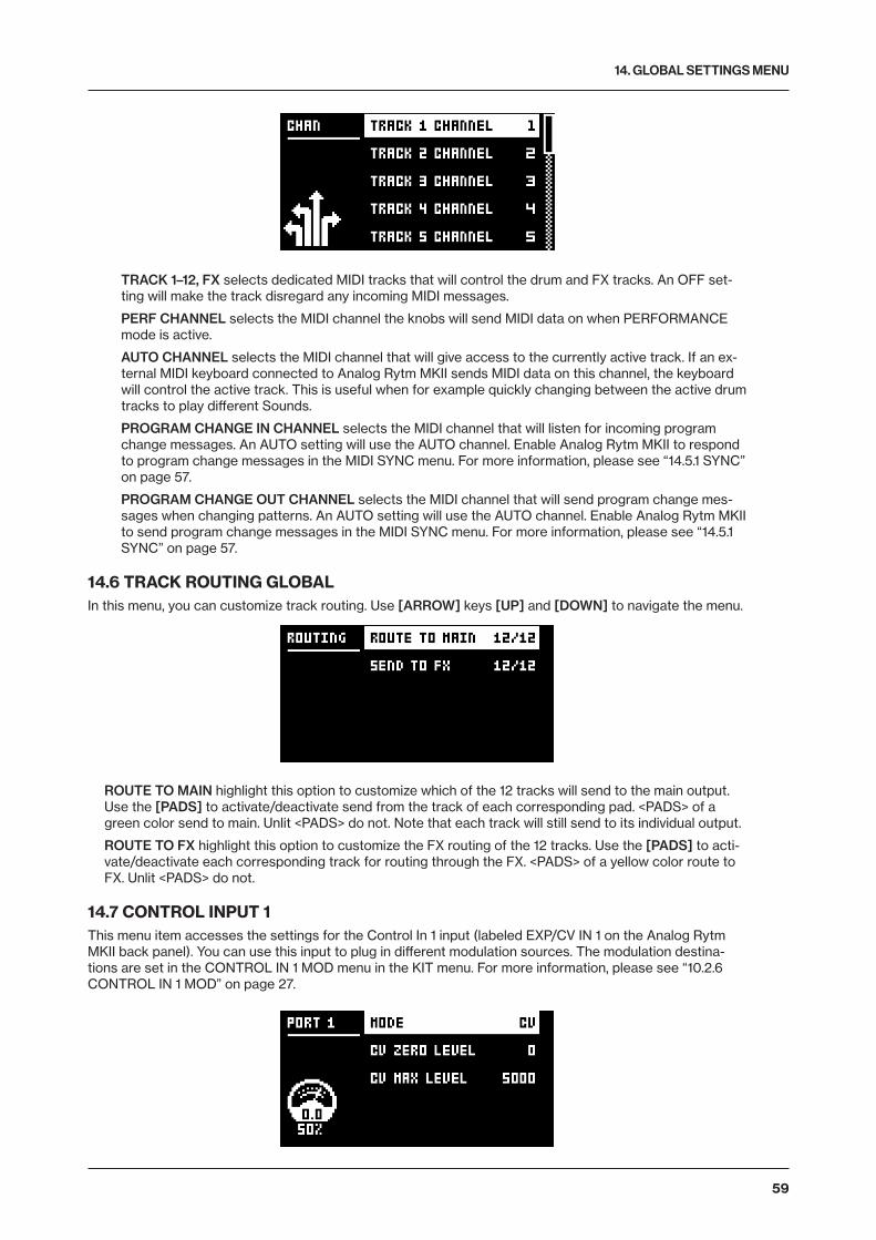
14. GLOBAL SETTINGS MENU
59
TRACK 1–12, FX selects dedicated MIDI tracks that will control the drum and FX tracks. An OFF set-ting will make the track disregard any incoming MIDI messages.
PERF CHANNEL selects the MIDI channel the knobs will send MIDI data on when PERFORMANCE mode is active.
AUTO CHANNEL selects the MIDI channel that will give access to the currently active track. If an ex-ternal MIDI keyboard connected to Analog Rytm MKII sends MIDI data on this channel, the keyboard will control the active track. This is useful when for example quickly changing between the active drum tracks to play different Sounds.
PROGRAM CHANGE IN CHANNEL selects the MIDI channel that will listen for incoming program change messages. An AUTO setting will use the AUTO channel. Enable Analog Rytm MKII to respond to program change messages in the MIDI SYNC menu. For more information, please see “14.5.1 SYNC” on page 57.
PROGRAM CHANGE OUT CHANNEL selects the MIDI channel that will send program change mes-sages when changing patterns. An AUTO setting will use the AUTO channel. Enable Analog Rytm MKII to send program change messages in the MIDI SYNC menu. For more information, please see “14.5.1 SYNC” on page 57.
14.6 TRACK ROUTING GLOBALIn this menu, you can customize track routing. Use [ARROW] keys [UP] and [DOWN] to navigate the menu.
ROUTE TO MAIN highlight this option to customize which of the 12 tracks will send to the main output. Use the [PADS] to activate/deactivate send from the track of each corresponding pad. <PADS> of a green color send to main. Unlit <PADS> do not. Note that each track will still send to its individual output.
ROUTE TO FX highlight this option to customize the FX routing of the 12 tracks. Use the [PADS] to acti-vate/deactivate each corresponding track for routing through the FX. <PADS> of a yellow color route to FX. Unlit <PADS> do not.
14.7 CONTROL INPUT 1This menu item accesses the settings for the Control In 1 input (labeled EXP/CV IN 1 on the Analog Rytm MKII back panel). You can use this input to plug in different modulation sources. The modulation destina-tions are set in the CONTROL IN 1 MOD menu in the KIT menu. For more information, please see “10.2.6 CONTROL IN 1 MOD” on page 27.

14. GLOBAL SETTINGS MENU
60
MODE Sets the port mode to adjust to different kinds of input signals. There are three modes: CV (Control Volt-age), EXPR (Expression Pedal), and OFF.CV ZERO LEVEL (Available when MODE is set to CV.) Sets the Volt level at which CV modulation amount is zero. A control input level equal to this setting cor-responds to zero modulation. (-5.50 V–+5.50 V).CV MAX LEVEL (Available when MODE is set to CV.) Sets the Volt level at which CV modulation amount is max. A control input level equal to this setting cor-responds to full modulation. (-5.50 V–+5.50 V).EXPRESSION LEARN (Available when MODE is set to EXPR.) Sets the highest and lowest limit of the control input level. When in this setting, connect the Expression pedal to CONTROL IN A/B. Press YES and then move the expression pedal first to max and then to min position. Press YES to save settings.REVERSE DIRECTION (Available when MODE is set to EXPR.) Reverses the direction of how the Expression pedal sends control input signals.
14.8 CONTROL INPUT 2The available settings are the same as for CONTROL INPUT 1.
14.9 SYSEX DUMPIn the SYSEX DUMP menu, kits, Sounds, patterns, songs and global slots can be sent and received. Note that Sample transfer is handled exclusively via the SAMPLES menu (see above). Select a menu option using [UP]/[DOWN] or the TRACK LEVEL knob. Press [YES] to open the highlighted menu selection.
When receiving or sending SysEx data, the MIDI ports or the USB port of Analog Rytm MKII must be con-nected to the external sending/receiving device.
• If the external device is a computer, we recommend using our free SysEx utility C6, which can be downloaded from the Elektron website.
14.9.1 SYSEX SENDHere kits, Sounds, patterns, songs and global slots can be sent to an external device via the MIDI OUT port or the USB port of Analog Rytm MKII.
The column to the left selects what will be backed up. Select the column using the [LEFT] arrow key. Use the [UP]/[DOWN] keys or the TRACK LEVEL knob to scroll through the column. The SysEx data send alternatives located in the column to the right will change depending on the selection made in the left column. Press the [RIGHT] arrow key to access this column. Use the [UP]/[DOWN] keys or the TRACK LEVEL knob to select what will be sent. Press [YES] to initiate the SysEx send procedure.
ALL offers the possibility to do complete backups of various data.
• WHOLE PROJECT sends all kits, Sounds, patterns, songs and global slots + settings to the receiving device. I.e. the complete project.

14. GLOBAL SETTINGS MENU
61
• ALL SOUNDS sends all Sounds to the receiving device.
• ALL KITS sends all kits to the receiving device.
• ALL PATTERNS sends all patterns to the receiving device.
• ALL SONGS sends all songs to the receiving device.
• ALL GLOBALS sends all global slots to the receiving device.
• ALL SETTINGS sends all settings to the receiving device.
KIT sends the selected kit to the receiving device. An asterisk at the end of the kit name indicates the kit is not linked to any pattern.
SOUND sends the selected Sound to the receiving device.
PATTERN sends the selected pattern to the receiving device. To the right of the pattern slot, the name of the kit linked to the pattern is visible. An asterisk indicates the pattern is not linked to a kit.
PATTERN + KIT sendsthe send the selected pattern plus its associated kit to the receiving device.
SONG sends the selected Song to the receiving device.
GLOBAL sends the selected Global slot to the receiving device.
• Backing up your data regularly is important!• Before initiating a SysEx send, first, make sure the receiving device is listening for data
to be sent. If C6 is used, once transmission is complete, always check that none of the objects are broken
14.9.2 SYSEX RECEIVEHere kits, Sounds, patterns, songs and global slots can be received from an external device via the MIDI IN port or the USB port of Analog Rytm MKII.
The column to the left selects what will be received. Select the column using the [LEFT] arrow key. Use the [UP]/[DOWN] keys or the TRACK LEVEL knob to scroll through the column. The SysEx data receive alternatives located in the column to the right will change depending on the selection made in the left column. Press the [RIGHT] arrow key to access this column. Use the [UP]/[DOWN] keys or the TRACK LEVEL knob to select what will be received. Press [YES] to initiate the SysEx receive procedure. Analog Rytm MKII will start listening to incoming data. Press [NO] to stop listening.
ANYTHING will listen to and receive any viable SysEx data sent.
KIT will exclusively listen to and receive kit data.
• ACTIVE KIT will when receiving kit SysEx data replace currently active kit with the received kit.
• KIT 01–128 will store a received kit to the selected kit slot. An asterisk at the end of the kit name indicates the kit is not linked to any pattern.
SOUND POOL will store a received Sound to the selected slot of the Sound Pool of the active project.
+DRIVE SOUND will store a received Sound to the selected slot of the +Drive Sound library. The option ANYWHERE will place the Sound in the first free slot available. To the right of the bank indication, the number of free slots can be seen.
PATTERN will store a received pattern to the selected pattern slot. To the right of the pattern slot, the name of the kit linked to the pattern is visible. An asterisk indicates the pattern is not linked to a kit.
SONG will store a received song to the selected song slot.
GLOBAL will store a received global to the selected global slot.

14. GLOBAL SETTINGS MENU
62
• Initiate the SysEx send from the sending device after Analog Rytm MKII has started listening to incoming data.
• When receiving to a specific list position, any subsequent data will be received on the next position, or positions, in the list.
• Analog Rytm MKII can receive SysEx data at any time, regardless of the currently active menu. The data will be loaded into the position specified when it was saved, or to the first free slot if unspecified.
14.10 SYSTEMThe System menu contains USB CONFIG, OS UPGRADE, FORMAT +DRIVE, CALIBRATION and VERIFY FACTORY SAMPLES options for the Analog Rytm MKII.
14.10.1 USB CONFIGTo use the Analog Rytm MKII as an Overbridge device (For more information, please see “6.6 OVER-BRIDGE” on page 18.) you must set it to Overbridge mode. Do so by selecting the OVERBRIDGE MODE menu item and ticking the box by pressing [YES].
Should you, for some reason, wish to disable the Overbridge integration functionality, select the item called USB-MIDI ONLY and press [YES].
14.10.2 OS UPGRADEUse this menu option is used when you want to upgrade the Analog Rytm MKII OS. To send the OS syx file, use our free Elektron Transfer software. The OS syx file and Elektron Transfer can be downloaded from the Elektron website.
For the transfer to be possible, the device sending the OS syx file must be connected to either the MIDI IN or USB port of Analog Rytm MKII.
Please note that the Analog Rytm MKII will not appear as an icon on your computer desktop.
1. Press [YES] to make Analog Rytm MKII start listening for incoming OS SysEx data. If you wish to cancel the waiting state, press [NO].
2. Open Elektron Transfer and select Elektron Analog Rytm MKII for MIDI Input device as well as MIDI Output device.
3. Drag and drop the syx file to the Elektron Transfer main window to send it to the Analog Rytm MKII.
A progress bar is visible on the Analog Rytm MKII screen when receiving the OS. When the process is successfully completed, the OS is updated and the unit reboots.
If you wish to cancel the waiting state, press [NO].
For the transfer to be possible, the device sending the OS syx-file must be connected to either the MIDI IN or USB port of Analog Rytm MKII.
Please note that the Analog Rytm MKII will not appear as an icon on your computer desktop.
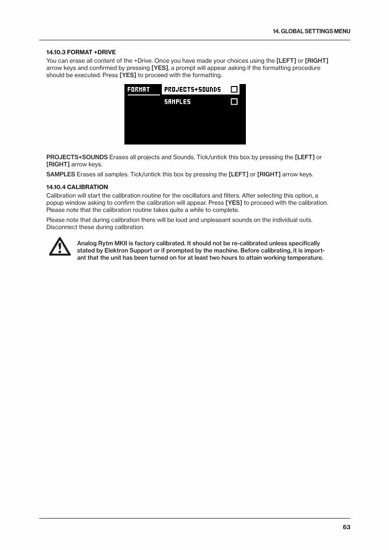
14. GLOBAL SETTINGS MENU
63
14.10.3 FORMAT +DRIVEYou can erase all content of the +Drive. Once you have made your choices using the [LEFT] or [RIGHT] arrow keys and confirmed by pressing [YES], a prompt will appear asking if the formatting procedure should be executed. Press [YES] to proceed with the formatting.
PROJECTS+SOUNDS Erases all projects and Sounds. Tick/untick this box by pressing the [LEFT] or [RIGHT] arrow keys.
SAMPLES Erases all samples. Tick/untick this box by pressing the [LEFT] or [RIGHT] arrow keys.
14.10.4 CALIBRATIONCalibration will start the calibration routine for the oscillators and filters. After selecting this option, a popup window asking to confirm the calibration will appear. Press [YES] to proceed with the calibration. Please note that the calibration routine takes quite a while to complete.
Please note that during calibration there will be loud and unpleasant sounds on the individual outs. Disconnect these during calibration.
Analog Rytm MKII is factory calibrated. It should not be re-calibrated unless specifically stated by Elektron Support or if prompted by the machine. Before calibrating, it is import-ant that the unit has been turned on for at least two hours to attain working temperature.
15. STARTUP MENU
64
15. STARTUP MENUTo access this menu, hold down the [FUNC] key while powering up Analog Rytm MKII. From here you can perform a variety of tasks. To choose the different alternatives, press the corresponding [TRIG] key.
15.1 TEST MODETo enter this mode, press the[TRIG 1] key.
Warning: For testing purposes, a short loud beep is heard through all outputs of the unit.
If you have any trouble with your Analog Rytm MKII and suspect it may be due to a hardware problem, perform this self-test. No errors should be reported as shown below. If that is not the case, contact Elektron support or the retailer that you bought Analog Rytm MKII from. The [UP] and [DOWN] keys can be used to scroll through the test log.
15.2 EMPTY RESETTo perform this operation, press the [TRIG 2] key. All kits, patterns, Sounds and songs will be erased. The +Drive remains intact.
15.3 FACTORY RESETWhen performing a factory reset on the Analog Rytm MKII, it will overwrite and re-initialize the active RAM project (including all pattern, kit, sound pool and global data). The +Drive project slot 1 will be overwritten and re-initialized with factory preset patterns, kits, Sounds and settings. Sound bank A will be overwritten with the factory Sounds.
If you wish to keep the active project, remember to save it to a +Drive project slot higher than 1 before you perform a factory reset. To perform a factory reset, press the [TRIG 3] key.
15.4 OS UPGRADEInitiate the OS upgrade by pressing the [TRIG 5] key. Analog Rytm MKII will enter a waiting stage, listen-ing for incoming OS data, and “READY TO RECEIVE” will be shown on the screen. For the transfer to be possible, the device sending the OS syx file should be connected to the MIDI IN port of Analog Rytm MKII. To send the OS syx file, use our free SysEx utility software C6. The OS syx file and the C6 software can be downloaded from the Elektron website.
USB MIDI transfers are not possible when in the STARTUP menu.
Please note that the Analog Rytm MKII will not appear as an icon on your computer desktop.
On your computer, download the OS syx file, open the C6 software. Click “Configure” and select Elektron Analog Rytm MKII for MIDI In as well as MIDI Out. Drag the syx file to the C6 main window, then highlight it by pointing and clicking on it with the mouse pointer. Point and click on the “send” button in the top left corner of the C6 window.
As the Analog Rytm MKII receives the OS a progress bar will show how much of the OS has been received. When the transfer is finished the message “UPGRADING... DO NOT TURN OFF” appears. During the up-grade, the [TRIG] keys will light up one after another, first in a dimly lit cycle (erasing the old OS) and then in a second cycle with fully lit LEDs (writing the new OS). Please note that this takes a little while. When this process is finished, the OS is updated, and the unit restarts.
• When you send the OS syx file, use our free SysEx utility C6. You can download it from the Elektron website.
15.5 EXITPress the [TRIG 5] key to exit the STARTUP menu.

16. SETUP EXAMPLES
65
16. SETUP EXAMPLESThe Analog Rytm MKII likes to play with other machines. Whether it uses its ability to sync and play with legacy machines, plays its part among other Elektron machines or plays with incoming audio: Analog Rytm MKII gets along with other gear. Three examples are shown here.
16.1 ANALOG RYTM MKII WITH A MONOPHONIC BASS MACHINE
MAIN OUT TO MIXER MONO PHONE TO MIXER
DIN SYNC 24
The DIN sync capabilities of the Analog Rytm MKII allows you to use gear from times gone by.
In this example, a legacy monophonic bass machine is used alongside the Analog Rytm MKII. The bass machine bassline is started, stopped and tempo controlled with the Analog Rytm MKII.
1. Prepare a bassline pattern on the bass machine.
2. Connect the output of the bass machine to the mixer using a standard phone cable.
3. Connect the Analog Rytm MKII outputs to the mixer using standard phone cables.
4. Connect the MIDI Out of the Analog Rytm MKII to the SYNC IN of the bass machine.
5. In the GLOBAL SETTINGS > MIDI PORT CONFIGURATION menu of the Analog Rytm MKII, set OUT PORT FUNC to DIN24
6. Prepare a rhythm on the Analog Rytm MKII.
16.2 ANALOG RYTM MKII WITH A STEREOPHONIC DRUM MACHINE
DIN SYNC 24
MONO TO STEREO SPLIT PHONE
MAIN OUT TO MIXER

16. SETUP EXAMPLES
66
Use the Analog Rytm MKII compressor when you incorporate sounds from external instruments in your composition.
The following example shows how an old drum machine is hooked up to the Analog Rytm MKII. The stereo output from the drum machine can be compressed to fit in nicely, and its patterns started, stopped and tempo controlled, using the Analog Rytm MKII.
1. Prepare a rhythm pattern on your heritage drum machine.
2. Connect the stereo outputs of the drum machine to the inputs of the Analog Rytm MKII using a mono to stereo split phone cord.
3. Connect the MIDI Out of the Analog Rytm MKII to the SYNC of the drum machine.
4. In the GLOBAL SETTINGS > MIDI PORT CONFIGURATION menu of the Analog Rytm MKII, set OUT PORT FUNC to DIN24.
5. Start the rhythm on the drum machine and access the COMPRESSOR of the Analog Rytm MKII by pressing the [FX] key, then the [AMP] key. Set the parameters according to taste.
6. Prepare a rhythm on the Analog Rytm MKII.
16.3 ANALOG RYTM MKII WITH OTHER ELEKTRON GEAR
To P.A.
Analog Rytm MKII works very well together with other Elektron devices. Here, it is used together with an Octatrack MKII and an Analog Four MKII.

16. SETUP EXAMPLES
67
In this example, the Analog Rytm MKII creates the beats. The Analog Four MKII is used for bass and synth sounds. The Octatrack MKII plays back loops and samples the audio from the Analog Rytm MKII and the Analog Four MKII.
1. Connect the Analog Rytm MKII main outputs to the Analog Four MKII inputs, the Analog Four MKII main outputs to one of the input pairs of the Octatrack MKII, and the main outputs of the Octatrack MKII to the PA.
2. Make sure the Analog machines are MIDI slaved to the Octatrack MKII using two standard MIDI cables.
3. In GLOBAL SETTINGS > MIDI CONFIG > SYNC menu on the Analog Rytm MKII, ensure that CLOCK RECEIVE, and PROG CH RECEIVE is active.
4. In GLOBAL SETTINGS > MIDI CONFIG > PORT CONFIG menu on the Analog Rytm MKII, set INPUT FROM to MIDI or MIDI+USB.
5. Use the internal effects of the Analog Four MKII on the incoming signal from the Analog Rytm MKII. Make a performance macro on the Analog Four MKII that controls the desired FX parameters.

17. USEFUL KEY COMBINATIONS (QUICK KEYS)
68
17. USEFUL KEY COMBINATIONS (QUICK KEYS)Use the key combinations below to quickly perform certain tasks.
GENERAL[FUNC] + [RECORD] will perform a copy command. Action depends on the currently active page or mode.
[FUNC] + [PLAY] will perform a clear command. Action depends on the currently active page or mode.
[FUNC] + [STOP] will perform a paste command. Action depends on the content that was copied.
NAMING[FUNC] + [ARROW] (on the NAMING screen) to choose a letter.
[FUNC] + [NO] (on the NAMING screen) to erase a letter.
ASSIGN SYNTH / SAMPLEDouble-press [SRC] to access MACHINE (Synth engine) selection.
Double-press [SMPL] to access SAMPLE selection (from the 127 user samples of the active Kit).
When SAMPLE selection is open, pick a slot and press [FUNC] + [YES] to access +Drive samples.
SAVING AND RELOADING[YES] + [PLAY MODE] will save Kit.
[NO] + [PLAY MODE] will reload Kit.
[YES] + [MUTE] will save Sound.
[NO] + [MUTE] will reload Sound.
[YES] + [SCNE] will save Pattern.
[NO] + [SCNE] will reload Pattern.
[YES] + [CHRO] will save Track.
[NO] + [CHRO] will reload Track.
[YES] + [PERF] will save Song.
[NO] + [PERF] will reload Song.
MENU ACCESS[GLOBAL SETTINGS] to open the GLOBAL SETTINGS menu.
[FUNC] + [PLAY MODE] to open the KIT menu.
[FUNC] + [MUTE] to open the SOUND menu.
Double-press [TRK] to open the SOUND BROWSER.
SEQUENCER SETTINGS[FUNC] + [TEMPO] to tap tempo.
[FUNC] + [RTRG] to access the CLICK TRACK settings.
[FUNC] + [TRIG] to access the QUANTIZE settings.
[FUNC] + [PAGE] to access the pattern / track SCALE settings.
MUTES AND SOLO[FUNC] + [PADS] will mute/unmute one or several Tracks (activate by releasing [FUNC]).
[RTRG] + [PADS] to solo enable Track (multiple Tracks may be solo:ed).
SEQUENCER RECORDING[RECORD] + [PLAY] to start LIVE RECORDING.
[RECORD] + double-tap [PLAY] will activate/deactivate QUANTIZE LIVE RECORDING.
[NO] + one of the [PADS] during LIVE RECORDING to clear the trigs from a sequencer track.
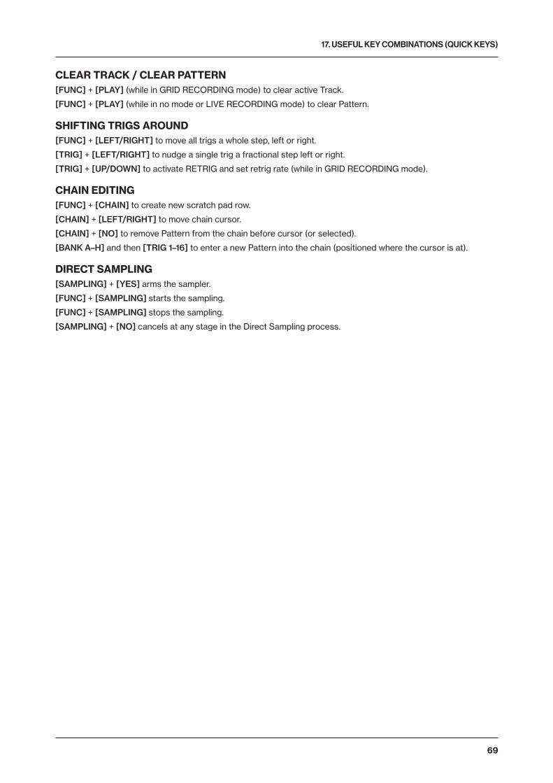
17. USEFUL KEY COMBINATIONS (QUICK KEYS)
69
CLEAR TRACK / CLEAR PATTERN[FUNC] + [PLAY] (while in GRID RECORDING mode) to clear active Track.
[FUNC] + [PLAY] (while in no mode or LIVE RECORDING mode) to clear Pattern.
SHIFTING TRIGS AROUND[FUNC] + [LEFT/RIGHT] to move all trigs a whole step, left or right.
[TRIG] + [LEFT/RIGHT] to nudge a single trig a fractional step left or right.
[TRIG] + [UP/DOWN] to activate RETRIG and set retrig rate (while in GRID RECORDING mode).
CHAIN EDITING[FUNC] + [CHAIN] to create new scratch pad row.
[CHAIN] + [LEFT/RIGHT] to move chain cursor.
[CHAIN] + [NO] to remove Pattern from the chain before cursor (or selected).
[BANK A–H] and then [TRIG 1–16] to enter a new Pattern into the chain (positioned where the cursor is at).
DIRECT SAMPLING[SAMPLING] + [YES] arms the sampler.
[FUNC] + [SAMPLING] starts the sampling.
[FUNC] + [SAMPLING] stops the sampling.
[SAMPLING] + [NO] cancels at any stage in the Direct Sampling process.

18. TECHNICAL INFORMATION
70
18. TECHNICAL INFORMATION
SPECIFICATIONS
ELECTRICAL SPECIFICATIONSImpedance balanced audio outputs: Main outputs level: +15 dBu Output impedance: 440 Ω unbalanced
Individual outputs: Output level: +15 dBu Output Impedance: 440 Ω
Headphones output: Headphones out level: +15 dBu Output impedance: 55 Ω
Unbalanced external inputs: Input level: +15 dBu maximum Audio input impedance: 9 kΩ
Balanced audio inputs: Input level: +15 dBu maximum Audio input impedance: 19 kΩ Digital S/N ratio: 110 dB (20–20,000 Hz)
Unit power consumption: 14 W typical, 20 W maximum. Recommended power supply: PSU-3b or similar 12 V DC, 2A
HARDWARE128 × 64 pixel OLED screen MIDI In/Out/Thru with DIN Sync out 2 x 1/4” impedance balanced audio out jacks 1 x 1/4” stereo headphone jack 8 x 1/4” impedance balanced individual track output jacks 2 × 1/4” balanced audio in jacks 2 × 1/4” ext in jacks 2 × 1/4” CV/Expression inputs 48 kHz, 24-bit D/A, and A/D converters Flash-EEPROM upgradable OS Electrically isolated USB 2.0 port
PHYSICAL SPECIFICATIONSAluminum enclosure Dimensions: W385 × D225 × H82 mm (15.2 × 8.85 × 3.3″) including knobs, jacks, and feet Weight: approximately 2.4 kg (5.3 lbs)
19. CREDITS AND CONTACT INFORMATION
CREDITS
PRODUCT DESIGN AND DEVELOPMENTOscar Albinsson Ali Alper Çakır Oscar Dragen Magnus Forsell Anders Gärder Andreas Henriksson Fabian Hundertmark Christer Lindström Jimmy Myhrman Jon Mårtensson Viktor Nilsson David Revelj Mattias Rickardsson Martin Sigby Daniel Troberg
ADDITIONAL DESIGNUfuk Demir Thomas Ekelund
DOCUMENTATIONDaniel Sterner Erik Ångman
CONTACT INFORMATION
ELEKTRON WEBSITEhttp://www.elektron.se
OFFICE ADDRESSElektron Music Machines MAV AB Sockerbruket 9 SE-414 51 Gothenburg Sweden
TELEPHONE+46 (0)31 743 744 0

APPENDIX A: DRUM TRACK PARAMETERS
71
APPENDIX A: DRUM TRACK PARAMETERSThis appendix lists the parameters on the five PARAMETER pages for the drum tracks and explains them. With one exception, each page contains the same parameters on all drum tracks. The exception is the SRC page, where parameters will vary depending on the active MACHINE.
A.1 SRCControls the (analog and digital) sound synthesis. The default parameters for the BD track with the BDHD machine are shown here. For the SRC pages of other machines, see “APPENDIX D: MACHINES” on page 88.
SYNTH (BDHD)
TUN (Tune) sets the pitch of the voltage controlled oscillator in chromatic semitones. (-64–+63)
SWT (Sweep Time) sets the pitch sweep time. Low values result in a short sweep, while high values result in a long sweep. (0–127)
SNP (Snap Amount) sets the amount of snap, an immediate pitch sweep at the start of the sound attack phase. Use together with TIC to shape the transient sound components. (0–127)
DEC (Decay) sets the length of the decay phase. Low values mean a steep, quick decay while high val-ues produce a more gentle slope and a sound of longer duration. (0–127)
WAV (Waveform) sets the voltage controlled oscillator waveform to sine, asymmetric sine or triangle. The three waveforms, in that order, produce sounds with increasing amounts of overtone content. (0, 1 or 2).
HLD (Hold) sets the length of the hold phase before the decay phase kicks in. Low values correspond to short hold time, high values correspond to longer hold time. Use to shape the body of the drum sound. (0–127)
TIC (Tick Level) sets the level of the transient tick sound. Use together with SNP to shape the composite transient sound. (0–127)
LEV (Level) sets the volume of the SYNTH sound. (0–127)
A.2 SMPLThe parameters on this page control the playback of the user samples. A project has 127 user sample slots. Within each kit, these samples may be dynamically allocated, modulated and customized.
SAMPLE
TUN (Tune) sets the pitch of the sample in equivalents of chromatic semitones. To move faster, press the knob while turning it. The knob works in a bipolar fashion, with 0, north, leaving the pitch unchanged. Range (-24–+24), equivalent to four octaves.
FIN (Fine Tune) fine tunes the pitch of the sample. This parameter is an offset from the TUN parameter. The knob works in a bipolar fashion. The whole range (-64–+63) spans one semitone down and one semitone up.

APPENDIX A: DRUM TRACK PARAMETERS
72
BR (Bit Reduction) increasing the value of this parameter decreases the resolution of the sample, making it more grainy. Use when you want the sound of your drum sample to punch dirty like the sound effects of classic coin-op fighting games. (0–127)
SMP (Sample Slot) turn this knob to browse the list of up to 127 samples loaded into the project. Turn the knob clockwise to scroll down the list, counter-clockwise to scroll up. The first position, OFF, plays no sample at all (OFF, 1–127).
STA (Start) sets the starting point for the playback of the sample. The extreme values of the range (0-120) are the very beginning and the very end of the sample, respectively. This is a codependent parame-ter and must be set together with END.
END (End) sets the end point for the playback of the sample. The extreme values of the range (0-120) are the very beginning and the very end of the sample, respectively. If the value of END is lower than the value of STA, the sample will be played back backward.
LOP (Loop) when OFF, the sample will be played back once every time it is trigged. When ON, the sam-ple will loop continuously for the length of the trig (set with LEN on the TRIG page), confined by the AMP page envelope parameter settings HLD and DEC. (1/0 - ON/OFF).
LEV (Level) sets the volume of the sample. (0–127)
A.3 FLTROn the FILTER page you will find all parameters that control the analog multimode filter and its associated envelope.
FILTER
ATK (Attack) sets the length of the attack phase of the filter envelope. (0–127)
DEC (Decay) sets the length of the decay of the filter envelope. (0–127)
SUS (Sustain Level) sets the sustain level of the filter envelope. (0–127)
REL (Release) sets the length of the release phase of the filter envelope. (0–127)
FRQ (Frequency) sets the cutoff frequency of the multimode filter. (0–127)
RES (Resonance) sets the resonance behavior of the filter. Resonance introduces a peak in the spec-trum at the cutoff frequency. With the Bandstop filter type, there is a notch instead of a peak. The notch will be at its widest at the lowest Resonance setting. (0–127)
TYP (Filter Type) selects the filter type. Seven types are available: 2-pole Lowpass, 1-pole Lowpass, Bandpass, 1-pole Highpass, 2-pole Highpass, Bandstop, and Peak. Technically all of them are resonant 2-pole filters, but the 1-pole types have a flatter spectrum like simple 1-pole filters and are convenient for equalizer duties.
ENV (Envelope Depth) sets the depth of modulation within the filter envelope. The knob is bipolar, mean-ing that both negative and positive modulation depth is available. Range (-64–+63)
A.4 AMPThe AMP page controls parameters for the amplitude envelope, overdrive, effects sends, panning and volume.

APPENDIX A: DRUM TRACK PARAMETERS
73
AMP
ATK (Attack) sets the length of the attack phase of the amp envelope. (0–127)
HLD (Hold) sets the length of the hold phase of the amp envelope before the decay phase kicks in. Range (AUTO, 1–127). The AUTO setting means the hold phase is determined by the time the pad of the drum track is physically pressed. Values in the range (1–127) fix the hold phase, from very short times at the left extreme to increasingly long times to the right, regardless of how long the pad is pressed.
DEC (Decay) sets the length of the decay phase of the amp envelope. (0–INF)
OVR (Overdrive) sets the overdrive (gain increase boost of the amp), located before the multimode filter in the signal path. (0–127)
DEL (Delay Send) sets the amount of the Sound that will be sent through to the Delay effect (see “AP-PENDIX B: FX TRACK PARAMETERS” on page 75). (0–127)
REV (Reverb Send) sets the amount of the Sound that will be sent through to the Reverb effect (see Appendix B). (0–127)
PAN (Pan) positions the Sound in the stereo field. The knob function is bipolar with 0 being the perfectly balanced midpoint, -64 sending all sound to the left channel and +63 sending all sound to the right.
VOL (Volume) sets the volume of amplification of the Sound. This parameter is independent of the overall track level. (0–127)
A.5 LFOThe LFO can be used to interfere creatively with any parameter found on the SRC, SMPL, FLTR and AMP pages. Customize the low-frequency oscillator behavior, orientation, and depth on this page.
LFO
SPD (Speed) sets the speed of the LFO. For the LFO to be synced to straight beats, try settings of 8, 16 or 32. The knob is bi-polar. The LFO cycle can be played backward by using negative values. (-64–+63)
MUL (Multiplier) multiplies the SPD parameter by the set factor. (x) multiplies the current tempo, (dot) syncs the LFO to 120 BPM regardless of the tempo. 24 settings: (12 tempo synced, 12 free).
FAD (Fade In/Out) makes it possible to fade in/fade out the LFO modulation. The knob is bipolar. Positive values give a fade-out, negative values give a fade-in. A mid position (0) will result in no fade in/fade out. (-64–+63)
DST (Destination) selects the destination for the LFO. A list will appear when you turn the knob. Choose a parameter from any of the parameter pages. Turn the knob clockwise to go down the list, counter-clockwise to go up. Preview how the LFO modulation will affect the sound by highlighting a destination. Confirm a selection by pressing [YES].
WAV (Waveform) sets the LFO waveform. There are seven waveforms: Triangle, Sine, Square, Sawtooth, Exponential, Ramp and Random.
SPH (Start Phase) sets the LFO cycle start position when it is trigged. Range (0-127). 0 is the start of a complete wave cycle and 127 is the end point. 64 is the dead center.
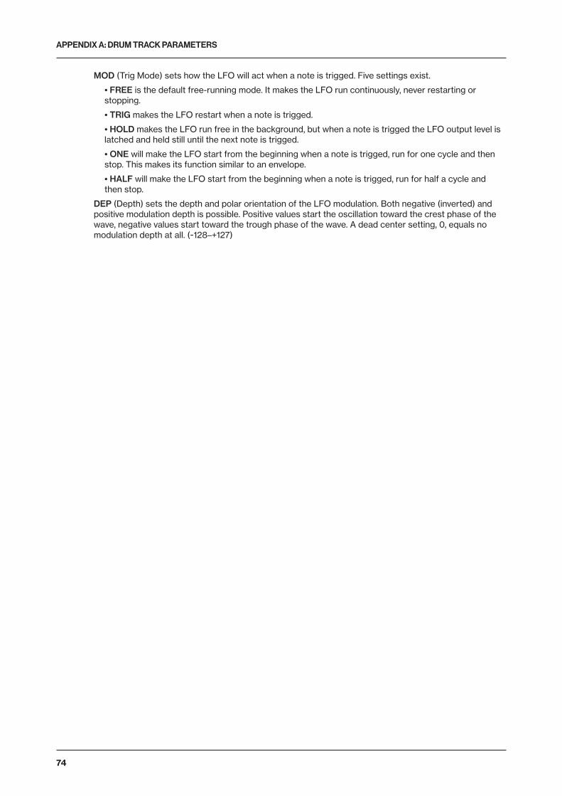
APPENDIX A: DRUM TRACK PARAMETERS
74
MOD (Trig Mode) sets how the LFO will act when a note is trigged. Five settings exist.
• FREE is the default free-running mode. It makes the LFO run continuously, never restarting or stopping.
• TRIG makes the LFO restart when a note is trigged.
• HOLD makes the LFO run free in the background, but when a note is trigged the LFO output level is latched and held still until the next note is trigged.
• ONE will make the LFO start from the beginning when a note is trigged, run for one cycle and then stop. This makes its function similar to an envelope.
• HALF will make the LFO start from the beginning when a note is trigged, run for half a cycle and then stop.
DEP (Depth) sets the depth and polar orientation of the LFO modulation. Both negative (inverted) and positive modulation depth is possible. Positive values start the oscillation toward the crest phase of the wave, negative values start toward the trough phase of the wave. A dead center setting, 0, equals no modulation depth at all. (-128–+127)

APPENDIX B: FX TRACK PARAMETERS
75
APPENDIX B: FX TRACK PARAMETERSIn this appendix, the parameters of the FX track are shown and explained, one page at a time.
B.1 DELAYThe Delay send effect takes a duplicate of the input signal, delays it in time and then rejoins it with the origi-nal signal. Customize the delay parameters on this page.
DELAY
TIM (Delay Time) sets the delay time. It is relative to the current BPM and is measured in 128th notes. For instance, a setting of 32 equals a one beat delay (four sixteenth notes). (1–128)
X (Pingpong) sets the delay signal to alternate across the stereo field. There are two settings:
• 0 (off) if you wish to manually set the position of the delay signal in the stereo field instead. Do so using the WID parameter.
• 1 (on) makes the delay signal alternate between left and right pan positions. The WID parameter controls the amount of panning.
WID (Stereo Width) sets the delay signal pan width across the stereo field. The knob is bipolar. (-64–+63)
FDB (Feedback) sets the amount of delay output signal to feed back into the input of the delay. With higher parameter settings, infinite and/or swelling delays are possible to achieve. Please be aware that high feedback can lead to a very loud signal, and that the DOV parameter on the DISTORTION page can further increase the harshness of the feedback. (1–198)
HPF (HP Filter) sets the cutoff frequency of the delay highpass filter. (0–127)
LPF (LP Filter) sets the cutoff frequency of the delay lowpass filter. (0–127)
REV (Reverb Send) sets the amount of Delay output signal to be sent to the Reverb. (0–127)
VOL (Mix Volume) adjusts the volume of the Delay output signal. The output is routed either before or after the Distortion and Compressor effects, depending on the setting of the DEL parameter on the DIS-TORTION page. (0–127)
B.2 REVERBThe Reverb send effect controls the persistence, and ambient characteristics, of the sound reverberations. It can simulate many different sonic locations, from great spaces to small confinements.
REVERB
PRE (Pre-delay) sets the pre-delay time of the Reverb. (0–127)
DEC (Decay) sets the length of the decay phase of the reverberated signal, essentially setting the size of the acoustic space. (1–INF)
FRQ (Shelving Frequency) sets the shelving filter frequency. Together with the GAI parameter, it can be used to dampen the reverberated signal above a chosen frequency, making the reverberation sound more poignant or more muffled. (0–127)

APPENDIX B: FX TRACK PARAMETERS
76
GAI (Shelving Gain) affects the damping of the reverberated signal above the shelving frequency set by the FRQ parameter. At max value, the treble is included in the reverberations; lowering the value and gradually dampens it. (0–127)
HPF (HP Filter) sets the cutoff frequency of the reverb high-pass filter. (0–127)
LPF (LP Filter) sets the cutoff frequency of the reverb low-pass filter. (0–127)
VOL (Mix Volume) sets the volume of the Reverb output signal. The output is routed either before or after the Distortion and Compressor effects, depending on the setting of the REV parameter on the DISTOR-TION page. (0–127)
B.3 DISTORTIONThe distortion master effect pronounces the peaks of the signal and distorts them. Additionally, the sound may be offset in its entirety on this page and subjected to non-symmetrical distortion. This page also con-trols the overdrive of the Delay effect, as well as the routing of the Delay and Reverb effect returns.
DIST
AMT (Distortion Amount) sets the amount of distortion applied to the signal. (0–127)
SYM (Distortion Symmetry) offsets the whole signal (in the y-direction, if visualized as a wave cycle on a 2D graph) either up (positive values) or down (negative values) before applying distortion. This makes asymmetric distortion of the signal possible, fringing only the crests or the troughs of the wave. (-64–+63)
DOV (Delay Overdrive) sets the overdrive of the Delay effect, for a warm, dynamic distortion of the signal. Set this in conjunction with the FDB parameter on the DELAY page to produce anything from a tinge of shear to a very aggressive four-pound barrage of overtones. (0–127)
DEL (Delay Dist/Comp) sets the Delay effect to return before (PRE), or after (POST) the signal is subject to distortion and compression. The default setting is before. (PRE, POST)
REV (Reverb Dist/Comp) sets the Reverb effect to return before (PRE), or after (POST) the signal is subject to distortion and compression. The default setting is after. (PRE, POST)
B.4 COMPRESSORThe Compressor master effect compresses the dynamic range of the signal by reducing the volume of loud sounds relative to the quiet sounds. There are eight parameters with which the compressor is customized on this page.
COMP
THR (Threshold) sets the threshold of the compressor. A lower threshold means a larger portion of the signal will be subject to compression. There is a bar on the rightmost edge of the screen which will visu-ally represent the amount of compression. (0–127)
ATK (Attack) sets the time of the compressor attack phase, i.e., how quickly the compressor responds to loud peaks. The time of the attack phase is set in milliseconds. (0.03–30)

APPENDIX B: FX TRACK PARAMETERS
77
REL (Release) sets the time of the compressor release phase, i.e., how long it takes for the compression to recover in quieter moments. The time is set in seconds. Range (0.1–2, A1 or A2). A1 and A2 are two types of auto release phases, (A2) being slightly longer than (A1).
MUP (Makeup Gain) sets the makeup gain of the compressor output, to compensate for the reduced signal levels caused by compression. (0–127)
RAT (Compression Ratio) There are four different compression ratios, 1:2, 1:4, 1:8 and MAX. Higher ratios result in greater compression of the signal.
SEQ (Sidechain EQ) filters the signal before it is analyzed by the compressor in one of the following ways:
• OFF lets the sidechain signal remain unchanged.
• LPF lowpass filters the signal before analysis, making the compressor react mostly to the bass. Use this setting for a characteristic pumping compressor sound.
• HPF passes the signal through a highpass filter before it is analyzed, making the compressor react less to the bass. Use this setting to avoid pumping.
• HIT results in a balanced equalization of the sidechain signal, making the compressor react similarly to all frequencies of the signal.
MIX (Dry/Wet Mix) sets the mix of the uncompressed signal and the compressor output signal. The left extreme setting results in a completely uncompressed signal. The extreme right setting lets only the compressed signal pass through. All values in between mix the uncompressed signal with the com-pressed signal, also known as parallel compression. A definitive Motown compression effect may be achieved at moderate MIX settings combined with high RAT and low MUP settings. (0–127)
VOL (Volume) sets the volume of the output signal. (0–127)
B.5 FX LFOThe FX track LFO page parameters are shown and explained below.
LFO
SPD (Speed) sets the speed of the LFO. For the LFO to be synced to straight beats, try settings of 8, 16 or 32. The knob is bi-polar. The LFO cycle can be played backward by using negative values. (-64–+63)
MUL (Multiplier) multiplies the SPD parameter by the set factor. (x) multiplies the current tempo, (dot) syncs the LFO to 120 BPM regardless of the tempo. 24 settings: (12 tempo synced, 12 free).
FAD (Fade In/Out) makes it possible to fade in/fade out the LFO modulation. The knob is bipolar. Positive values give a fade-out, negative values give a fade-in. A mid position (0) will result in no fade in/fade out. (-64–+63)
DST (Destination) selects the destination for the LFO. A list will appear when you turn the knob. Choose a parameter from any of the parameter pages. Turn the knob clockwise to go down the list, counter-clockwise to go up. Preview how the LFO modulation will affect the sound by highlighting a destination. Confirm a selection by pressing [YES].
WAV (Waveform) sets the LFO waveform. There are seven waveforms: Triangle, Sine, Square, Sawtooth, Exponential, Ramp, and Random.
SPH (Start Phase) sets the wave phase where the LFO will start when it is trigged. (0–127) 0 is the start of a complete wave cycle, and 127 is the end point. 64 is the dead center.
MOD (Trig Mode) sets how the LFO will act when a note is trigged. Five settings exist.
• FREE is the default free-running mode. It makes the LFO run continuously, never restarting or stop-ping.
• TRIG makes the LFO restart when a note is trigged.

APPENDIX B: FX TRACK PARAMETERS
78
• HOLD makes the LFO run free in the background, but when a note is trigged the LFO output level is latched and held still until the next note is trigged.
• ONE makes the LFO start from the beginning when a note is trigged, run for one cycle and then stop, making the LFO act like an envelope.
• HALF makes the LFO start from the beginning when a note is trigged, run for half a cycle and then stop.
DEP (Depth) sets the depth and polar orientation of the LFO modulation. Both negative (inverted) and positive modulation depth is possible. Positive values start the oscillation toward the crest phase of the wave. Negative values start toward the trough phase of the wave. A dead center setting, 0, equals no modulation depth at all. (-128–+127)
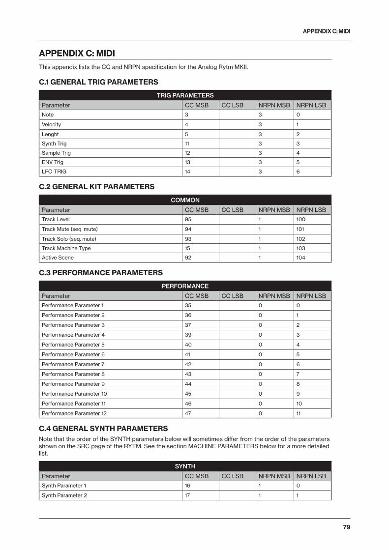
APPENDIX C: MIDI
79
APPENDIX C: MIDIThis appendix lists the CC and NRPN specification for the Analog Rytm MKII.
C.1 GENERAL TRIG PARAMETERS
TRIG PARAMETERS
Parameter CC MSB CC LSB NRPN MSB NRPN LSB
Note 3 3 0
Velocity 4 3 1
Lenght 5 3 2
Synth Trig 11 3 3
Sample Trig 12 3 4
ENV Trig 13 3 5
LFO TRIG 14 3 6
C.2 GENERAL KIT PARAMETERS
COMMON
Parameter CC MSB CC LSB NRPN MSB NRPN LSB
Track Level 95 1 100
Track Mute (seq. mute) 94 1 101
Track Solo (seq. mute) 93 1 102
Track Machine Type 15 1 103
Active Scene 92 1 104
C.3 PERFORMANCE PARAMETERS
PERFORMANCE
Parameter CC MSB CC LSB NRPN MSB NRPN LSB
Performance Parameter 1 35 0 0
Performance Parameter 2 36 0 1
Performance Parameter 3 37 0 2
Performance Parameter 4 39 0 3
Performance Parameter 5 40 0 4
Performance Parameter 6 41 0 5
Performance Parameter 7 42 0 6
Performance Parameter 8 43 0 7
Performance Parameter 9 44 0 8
Performance Parameter 10 45 0 9
Performance Parameter 11 46 0 10
Performance Parameter 12 47 0 11
C.4 GENERAL SYNTH PARAMETERSNote that the order of the SYNTH parameters below will sometimes differ from the order of the parameters shown on the SRC page of the RYTM. See the section MACHINE PARAMETERS below for a more detailed list.
SYNTH
Parameter CC MSB CC LSB NRPN MSB NRPN LSB
Synth Parameter 1 16 1 0
Synth Parameter 2 17 1 1

APPENDIX C: MIDI
80
SYNTH
Parameter CC MSB CC LSB NRPN MSB NRPN LSB
Synth Parameter 3 18 1 2
Synth Parameter 4 19 1 3
Synth Parameter 5 20 1 4
Synth Parameter 6 21 1 5
Synth Parameter 7 22 1 6
Synth Parameter 8 23 1 7
SAMPLE
Parameter CC MSB CC LSB NRPN MSB NRPN LSB
Sample Tune 24 1 8
Sample Fine tune 25 1 9
Sample Bit Reduction 26 1 10
Sample Slot 27 1 11
Sample Start 28 1 12
Sample End 29 1 13
Sample Loop 30 1 14
Sample Level 31 1 15
FILTER
Parameter CC MSB CC LSB NRPN MSB NRPN LSB
Filter Attack Time 70 1 16
Filter Decay Time 71 1 17
Filter Sustain Level 72 1 18
Filter Release Time 73 1 19
Filter Frequency 74 1 20
Filter Resonance 75 1 21
Filter Mode 76 1 22
Filter Env Depth 77 1 23
AMP
Parameter CC MSB CC LSB NRPN MSB NRPN LSB
Amp Attack Time 78 1 24
Amp Hold Time 79 1 25
Amp Decay Time 80 1 26
Amp Overdrive 81 1 27
Amp Delay Send 82 1 28
Amp Reverb Send 83 1 29
Amp Pan 10 1 30
Amp Volume 7 1 31

APPENDIX C: MIDI
81
C.5 LFO PARAMETERSNote that the LFO depth is a high-resolution parameter, with CC LSB value.
LFO
Parameter CC MSB CC LSB NRPN MSB NRPN LSB
LFO Speed 102 1 32
LFO Multiplier 103 1 33
LFO Fade In/Out 104 1 34
LFO Destination 105 1 35
LFO Waveform 106 1 36
LFO Start Phase 107 1 37
LFO Trig Mode 108 1 38
LFO Depth 109 118 1 39
C.6 FX PARAMETERS
DELAY
Parameter CC MSB CC LSB NRPN MSB NRPN LSB
Delay Time 16 2 0
Delay Pingpong 17 2 1
Delay Stereo Width 18 2 2
Delay Feedback 19 2 3
Delay Highpass Filter 20 2 4
Delay Lowpass Filter 21 2 5
Delay Reverb Send 22 2 6
Delay Mix Volume 23 2 7
REVERB
Parameter CC MSB CC LSB NRPN MSB NRPN LSB
Reverb Predelay 24 2 8
Reverb Decay Time 25 2 9
Reverb Shelving Freq 26 2 10
Reverb Shelving Gain 27 2 11
Reverb Highpass Filter 28 2 12
Reverb Lowpass Filter 29 2 13
Reverb Mix Volume 31 2 15
DISTORTION
Parameter CC MSB CC LSB NRPN MSB NRPN LSB
Dist Amount 70 2 16
Dist Symmetry 71 2 17
Delay Overdrive 72 2 18
Delay Dist/Comp Routing (pre/post) 76 2 22
Reverb Dist/Comp Routing (pre/post) 77 2 23
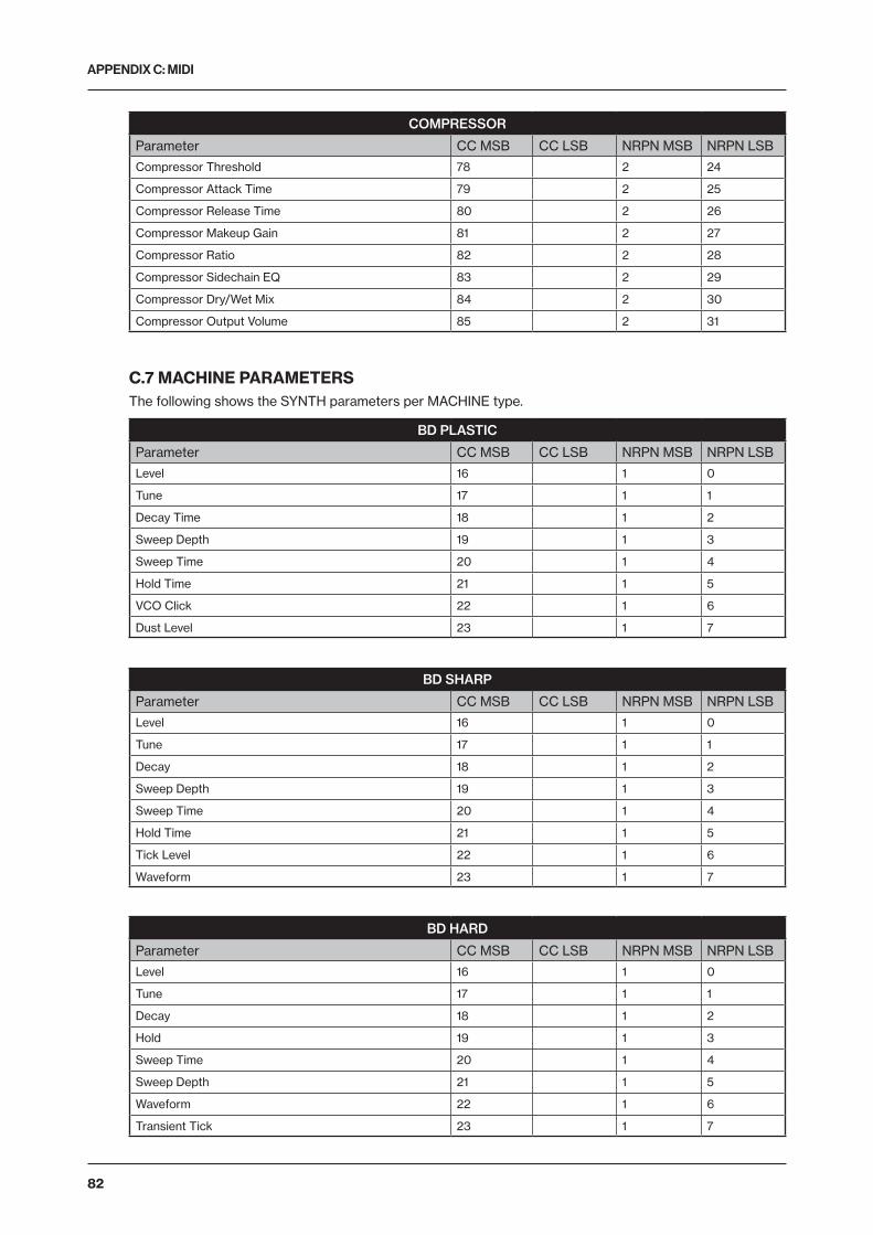
APPENDIX C: MIDI
82
COMPRESSOR
Parameter CC MSB CC LSB NRPN MSB NRPN LSB
Compressor Threshold 78 2 24
Compressor Attack Time 79 2 25
Compressor Release Time 80 2 26
Compressor Makeup Gain 81 2 27
Compressor Ratio 82 2 28
Compressor Sidechain EQ 83 2 29
Compressor Dry/Wet Mix 84 2 30
Compressor Output Volume 85 2 31
C.7 MACHINE PARAMETERSThe following shows the SYNTH parameters per MACHINE type.
BD PLASTIC
Parameter CC MSB CC LSB NRPN MSB NRPN LSB
Level 16 1 0
Tune 17 1 1
Decay Time 18 1 2
Sweep Depth 19 1 3
Sweep Time 20 1 4
Hold Time 21 1 5
VCO Click 22 1 6
Dust Level 23 1 7
BD SHARP
Parameter CC MSB CC LSB NRPN MSB NRPN LSB
Level 16 1 0
Tune 17 1 1
Decay 18 1 2
Sweep Depth 19 1 3
Sweep Time 20 1 4
Hold Time 21 1 5
Tick Level 22 1 6
Waveform 23 1 7
BD HARD
Parameter CC MSB CC LSB NRPN MSB NRPN LSB
Level 16 1 0
Tune 17 1 1
Decay 18 1 2
Hold 19 1 3
Sweep Time 20 1 4
Sweep Depth 21 1 5
Waveform 22 1 6
Transient Tick 23 1 7

APPENDIX C: MIDI
83
BD CLASSIC
Parameter CC MSB CC LSB NRPN MSB NRPN LSB
Level 16 1 0
Tune 17 1 1
Decay 18 1 2
Hold 19 1 3
Sweep Time 20 1 4
Sweep Depth 21 1 5
Waveform 22 1 6
Transient Tick 23 1 7
BD FM
Parameter CC MSB CC LSB NRPN MSB NRPN LSB
Level 16 1 0
Tune 17 1 1
Decay 18 1 2
FM Amount 19 1 3
Sweep Time 20 1 4
FM Sweep Time 21 1 5
FM Decay Time 22 1 6
FM Tune 23 1 7
BD SILKY
Parameter CC MSB CC LSB NRPN MSB NRPN LSB
Level 16 1 0
Tune 17 1 1
Decay 18 1 2
Sweep Depth 19 1 3
Sweep Time 20 1 4
Hold 21 1 5
VCO Click 22 1 6
Dust Level 23 1 7
SD NATURAL
Parameter CC MSB CC LSB NRPN MSB NRPN LSB
Level 16 1 0
Tune 17 1 1
Body Decay 18 1 2
Noise Decay 19 1 3
Noise LPF 20 1 4
Noise Balance 21 1 5
Noise Resonance 22 1 6
Noise HPF 23 1 7

APPENDIX C: MIDI
84
SD HARD
Parameter CC MSB CC LSB NRPN MSB NRPN LSB
Level 16 1 0
Tune 17 1 1
Decay 18 1 2
Sweep Depth 19 1 3
Tick Level 20 1 4
Noise Decay 21 1 5
Noise Level 22 1 6
Sweep Time 23 1 7
SD CLASSIC
Parameter CC MSB CC LSB NRPN MSB NRPN LSB
Level 16 1 0
Tune 17 1 1
Decay 18 1 2
Detune 19 1 3
Snap Amount 20 1 4
Noise Decay 21 1 5
Noise Level 22 1 6
Osc Balance 23 1 7
SD FM
Parameter CC MSB CC LSB NRPN MSB NRPN LSB
Level 16 1 0
Tune 17 1 1
Decay 18 1 2
FM Tune 19 1 3
FM Decay Time 20 1 4
Noise Decay 21 1 5
Noise Level 22 1 6
FM Amount 23 1 7
RS HARD
Parameter CC MSB CC LSB NRPN MSB NRPN LSB
Level 16 1 0
Tune 17 1 1
Decay 18 1 2
Sweep Depth 19 1 3
Tick Level 20 1 4
Noise Level 21 1 5
Symmetry 22 1 6
Sweep Time 23 1 7

APPENDIX C: MIDI
85
RS CLASSIC
Parameter CC MSB CC LSB NRPN MSB NRPN LSB
Level 16 1 0
Tune Osc 1 17 1 1
Decay 18 1 2
Osc Balance 19 1 3
Tune Osc 2 20 1 4
Symmetry 21 1 5
Noise Level 22 1 6
Tick Level 23 1 7
CP CLASSIC
Parameter CC MSB CC LSB NRPN MSB NRPN LSB
Level 16 1 0
Noise Tone 17 1 1
Noise Decay 18 1 2
Clap Number 19 1 3
Clap Rate 20 1 4
Noise Level 21 1 5
Random Claps 22 1 6
Clap Decay 23 1 7
BT CLASSIC
Parameter CC MSB CC LSB NRPN MSB NRPN LSB
Level 16 1 0
Tune 17 1 1
Decay 18 1 2
Noise Level 20 1 4
Snap Type 21 1 5
LT, MT, HT CLASSIC
Parameter CC MSB CC LSB NRPN MSB NRPN LSB
Level 16 1 0
Tune 17 1 1
Decay 18 1 2
Sweep Depth 19 1 3
Sweep Time 20 1 4
Noise Decay 21 1 5
Noise Level 22 1 6
Noise Tone 23 1 7

APPENDIX C: MIDI
86
CH CLASSIC
Parameter CC MSB CC LSB NRPN MSB NRPN LSB
Level 16 1 0
Tune 17 1 1
Decay 18 1 2
Color 19 1 3
CH METALLIC
Parameter CC MSB CC LSB NRPN MSB NRPN LSB
Level 16 1 0
Tune 17 1 1
Decay Time 18 1 2
OH CLASSIC
Parameter CC MSB CC LSB NRPN MSB NRPN LSB
Level 16 1 0
Tune 17 1 1
Decay 18 1 2
Color 19 1 3
OH METALLIC
Parameter CC MSB CC LSB NRPN MSB NRPN LSB
Level 16 1 0
Tune 17 1 1
Decay Time 18 1 2
HH BASIC
Parameter CC MSB CC LSB NRPN MSB NRPN LSB
Level 16 1 0
Tune 17 1 1
Decay Time 18 1 2
Tone 19 1 3
Transient Decay 20 1 4
Osc Reset 21 1 5
CY METALLIC
Parameter CC MSB CC LSB NRPN MSB NRPN LSB
Level 16 1 0
Tune 17 1 1
Decay Time 18 1 2
Tone 19 1 3
Transient Decay 20 1 4
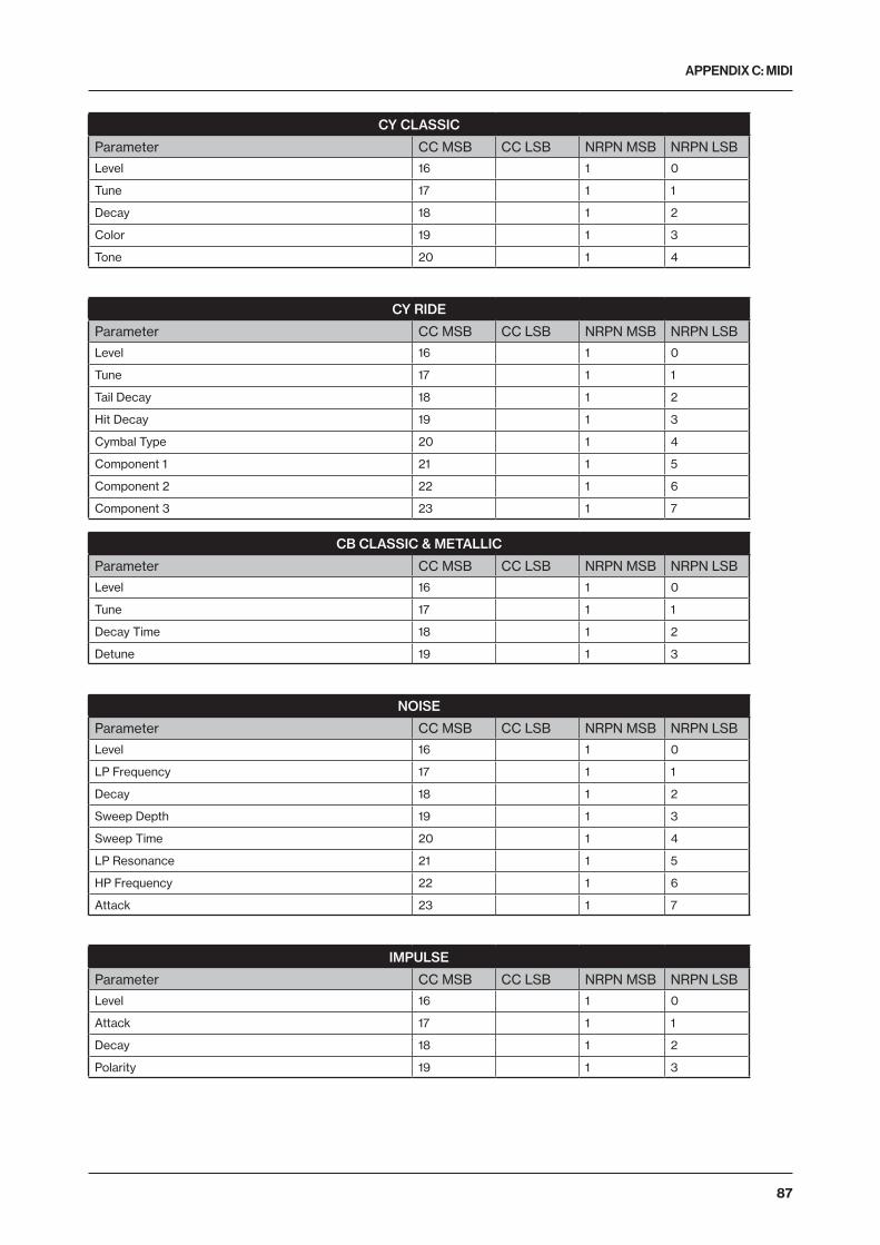
APPENDIX C: MIDI
87
CY CLASSIC
Parameter CC MSB CC LSB NRPN MSB NRPN LSB
Level 16 1 0
Tune 17 1 1
Decay 18 1 2
Color 19 1 3
Tone 20 1 4
CY RIDE
Parameter CC MSB CC LSB NRPN MSB NRPN LSB
Level 16 1 0
Tune 17 1 1
Tail Decay 18 1 2
Hit Decay 19 1 3
Cymbal Type 20 1 4
Component 1 21 1 5
Component 2 22 1 6
Component 3 23 1 7
CB CLASSIC & METALLIC
Parameter CC MSB CC LSB NRPN MSB NRPN LSB
Level 16 1 0
Tune 17 1 1
Decay Time 18 1 2
Detune 19 1 3
NOISE
Parameter CC MSB CC LSB NRPN MSB NRPN LSB
Level 16 1 0
LP Frequency 17 1 1
Decay 18 1 2
Sweep Depth 19 1 3
Sweep Time 20 1 4
LP Resonance 21 1 5
HP Frequency 22 1 6
Attack 23 1 7
IMPULSE
Parameter CC MSB CC LSB NRPN MSB NRPN LSB
Level 16 1 0
Attack 17 1 1
Decay 18 1 2
Polarity 19 1 3

APPENDIX D: MACHINES
88
APPENDIX D: MACHINESThis appendix lists the parameters on the SRC page of the drum tracks. The parameters available are determined by the MACHINE that has been selected. There are several MACHINES to choose from. See “ANALOG RYTM CONTROLS” on page 14 (illustration) for drum track voice allocation.
The MACHINES below can be used on all tracks: BD, SD, RS, CP, BT, LT, MT, HT, CH, OH, CY and CB.
D.1 ALL
NONE (SYNTH DISABLED)
There are no parameters on the SRC page when it is disabled. Select DISABLE, then save, to be able to make a sample-based Sound accessible, for loading and Sound Locking, on any of the 12 Tracks.
NOIS (WHITE NOISE GENERATOR)
LPF (LP Filter) sets the lowpass filter cutoff frequency. (0–127)
LPQ (LP Resonance) sets the amount of resonance around the cutoff frequency of the LP Filter. Zero value quenches resonance altogether (0–127)
ATK (Attack) sets the length of the attack phase. (0–127)
DEC (Decay) sets the length of the decay phase. (0–INF)
HPF (HP Filter) sets the highpass filter cutoff frequency. (0–127)
SWD (Sweep Depth) sets the depth of the LP Filter sweep. Negative as well as positive sweeps are possible. (-64–+63)
SWT (Sweep Time) sets the length of the sweep from the depth set by SWD. Low values result in snappy sweeps, high values result in longer sweeps. (0–127)
LEV (Level) sets the volume of noise. (0–127)
PULS (POSITIVE/NEGATIVE POLARITY IMPULSE)
ATK (Attack) sets the length of the attack phase. (0–127)
DEC (Decay) sets the length of the decay phase. (0–127)

APPENDIX D: MACHINES
89
POL (Polarity) sets the polarity, positive or negative. (POS, NEG)
LEV (Level) sets the volume of the impulse. (0–127)
The MACHINES below can be used on the BD, SD, RS and CP tracks.
D.2 BASS DRUM
BDHD (BASS DRUM HARD)
TUN (Tune) sets the pitch of the oscillator. (-64–63)
SWT (Sweep Time) sets the pitch sweep time. The depth of the sweep is fixed. (0–127)
SNP (Snap Amount) sets the snap transient level. (0–127)
DEC (Decay) sets the length of the decay phase. (0–127)
WAV (Waveform) sets the oscillator waveform to sine, asymmetric sine or triangle. (0, 1, 2)
HLD (Hold Time) sets the hold time, the time before the decay phase starts. (0–127)
TIC (Tick Level) sets the level of the transient tick. (0–127)
LEV (Level) sets the synth volume. (0–127)
BDCL (BASS DRUM CLASSIC)
TUN (Tune) sets the pitch of the oscillator. (-64–+63)
SWT (Sweep Time) sets the pitch sweep time. Low values result in a short sweep. (0–127)
SWD (Sweep Depth) sets the depth of the pitch sweep. (0–127)
DEC (Decay) sets the length of the decay phase. (0–127)
WAV (Waveform) sets the oscillator waveform to sine, asymmetric sine or triangle. (0–127)
HLD (Hold Time) sets the hold time, the time before the decay phase starts. (0–127)
TRA (Transient) sets the tick or noise transient sound and its level. (0–127)
LEV (Level) sets the synth volume. (0–127)
BDFM (BASS DRUM FM)
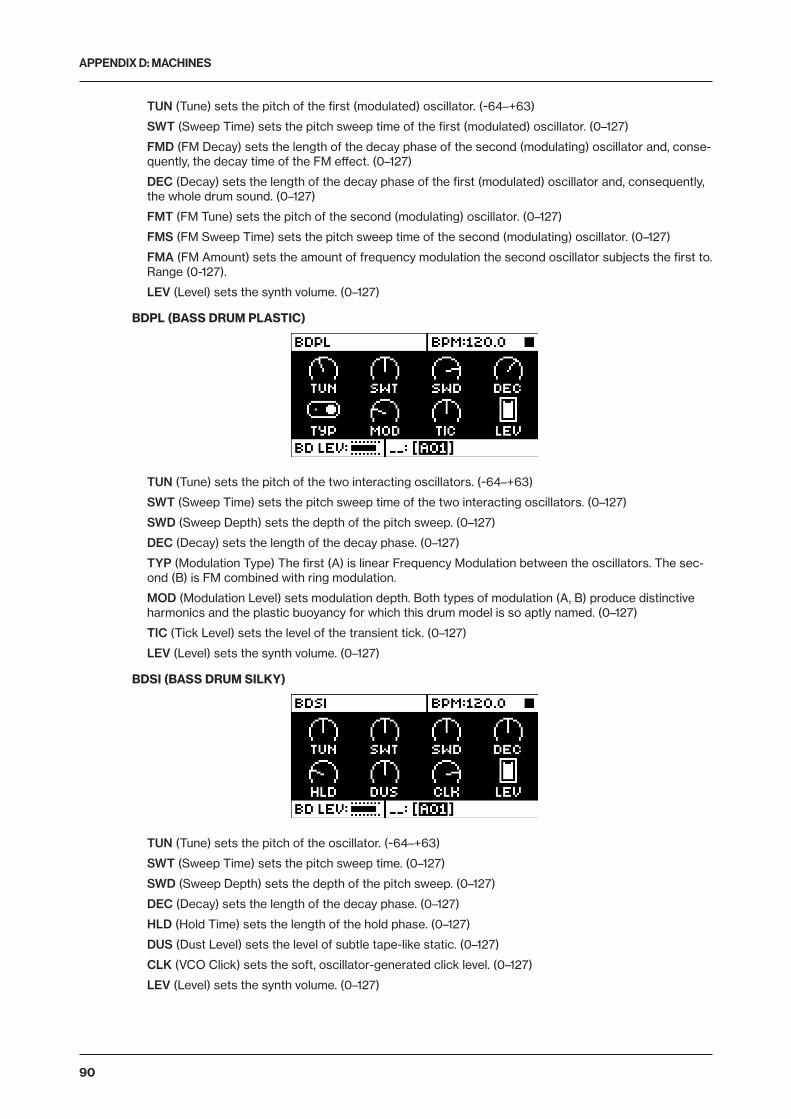
APPENDIX D: MACHINES
90
TUN (Tune) sets the pitch of the first (modulated) oscillator. (-64–+63)
SWT (Sweep Time) sets the pitch sweep time of the first (modulated) oscillator. (0–127)
FMD (FM Decay) sets the length of the decay phase of the second (modulating) oscillator and, conse-quently, the decay time of the FM effect. (0–127)
DEC (Decay) sets the length of the decay phase of the first (modulated) oscillator and, consequently, the whole drum sound. (0–127)
FMT (FM Tune) sets the pitch of the second (modulating) oscillator. (0–127)
FMS (FM Sweep Time) sets the pitch sweep time of the second (modulating) oscillator. (0–127)
FMA (FM Amount) sets the amount of frequency modulation the second oscillator subjects the first to. Range (0-127).
LEV (Level) sets the synth volume. (0–127)
BDPL (BASS DRUM PLASTIC)
TUN (Tune) sets the pitch of the two interacting oscillators. (-64–+63)
SWT (Sweep Time) sets the pitch sweep time of the two interacting oscillators. (0–127)
SWD (Sweep Depth) sets the depth of the pitch sweep. (0–127)
DEC (Decay) sets the length of the decay phase. (0–127)
TYP (Modulation Type) The first (A) is linear Frequency Modulation between the oscillators. The sec-ond (B) is FM combined with ring modulation.
MOD (Modulation Level) sets modulation depth. Both types of modulation (A, B) produce distinctive harmonics and the plastic buoyancy for which this drum model is so aptly named. (0–127)
TIC (Tick Level) sets the level of the transient tick. (0–127)
LEV (Level) sets the synth volume. (0–127)
BDSI (BASS DRUM SILKY)
TUN (Tune) sets the pitch of the oscillator. (-64–+63)
SWT (Sweep Time) sets the pitch sweep time. (0–127)
SWD (Sweep Depth) sets the depth of the pitch sweep. (0–127)
DEC (Decay) sets the length of the decay phase. (0–127)
HLD (Hold Time) sets the length of the hold phase. (0–127)
DUS (Dust Level) sets the level of subtle tape-like static. (0–127)
CLK (VCO Click) sets the soft, oscillator-generated click level. (0–127)
LEV (Level) sets the synth volume. (0–127)

APPENDIX D: MACHINES
91
BDSH (BASS DRUM SHARP)
TUN (Tune) sets the pitch of the oscillator. (-64–+63)
SWT (Sweep Time) sets the pitch sweep time. (0–127)
SWD (Sweep Depth) sets the depth of the pitch sweep. (0–127)
DEC (Decay) sets the length of the decay phase. (0–127)
HLD (Hold Time) sets the length of the hold phase. (0–127)
TIC (Tick Level) sets the level of transient tick. (0–127)
WAV (Waveform) sets the waveform. There are five waveforms to choose from (Sine, Asymmetric Sine, Triangle, Sinetooth and Sawtooth), and there is a choice between letting the oscillator run freely, or have it reset each time the synth is trigged (wave graphics showed with an anchor point on the LCD).
LEV (Level) sets the synth volume. (0–127)
D.3 SNARE DRUM
SDHD (SNARE DRUM HARD)
TUN (Tune) sets the pitch of the oscillators. The interval between them is fixed. (-64–+63)
SWT (Sweep Time) sets the pitch sweep time. (0–127)
SWD (Sweep Depth) sets the depth of the pitch sweep. (0–127)
DEC (Decay) sets the length of the decay phase. (0–127)
TIC (Tick Level) sets the level of the transient tick. (0–127)
NOD (Noise Decay) sets the length of the noise decay phase. (0–127)
NOL (Noise Level) sets the noise level. (0–127)
LEV (Level) sets the synth volume. (0–127)
SDCL (SNARE DRUM CLASSIC)
TUN (Tune) sets the common pitch of the oscillators. (-64–+63)
DET (Detune) sets the pitch of the second oscillator in relation to the first. (-64–+63)

APPENDIX D: MACHINES
92
BAL (Osc Balance) sets the balance between the levels of oscillator 1 and oscillator 2. (-64–+63)
DEC (Decay) sets the length of the decay phase. (0–127)
SNP (Snap Amount) sets the snap transient level. (0–127)
NOD (Noise Decay) sets the length of the noise decay phase. (0–127)
NOL (Noise Level) sets the noise level. (0–127)
LEV (Level) sets the synth volume. (0–127)
SDFM (SNARE DRUM FM)
TUN (Tune) sets the pitch of the first (modulated) oscillator. (-64–+63)
FMT (FM Tune) sets the pitch of the second (modulating) oscillator. (-64–63)
FMD (FM Decay Time) sets the decay time of the second (modulating) oscillator and, consequently, the decay time of the FM effect. (0–127)
DEC (Decay) sets the length of the decay phase of the first (modulated) oscillator and, consequently, the whole drum sound. (0–127)
FMA (FM Amount) sets the amount of frequency modulation the second oscillator subjects the first to. (0–127)
NOD (Noise Decay) sets the length of the noise decay phase. (0–127)
NOL (Noise Level) sets the noise level. (0–127)
LEV (Level) sets the synth volume. (0–127)
SDNA (SNARE DRUM NATURAL)
TUN (Tune) sets the pitch of the first oscillator. (-64–+63)
DEC (Noise Decay) sets the length of the noise decay. (0–127)
BAL (Noise Balance) sets the balance between noise and oscillator. (0–127)
BDY (Decay Time) sets the length of the decay phase of the oscillator. (0–127)
HPF (Noise HPF) sets the noise highpass filter cutoff frequency. (0–127)
LPF (Noise LPF) sets the noise lowpass filter cutoff frequency. (0–127)
RES (Noise Resonance) adds a resonant peak to the Noise LPF. Zero value quenches noise reso-nance altogether. (0–127)
LEV (Level) sets the synth volume. (0–127)

APPENDIX D: MACHINES
93
The MACHINES below can only be used on the RS and CP tracks.
D.4 RIMSHOT
RSHD (RIMSHOT HARD)
TUN (Tune) sets the pitch of the oscillators. (-64–+63)
SWT (Sweep Time) sets the pitch sweep time. (0–127)
SWD (Sweep Depth) sets the depth of the pitch sweep. (0–127)
DEC (Decay) sets the length of the decay phase. (0–127)
SYM (Symmetry) adjusts the nonlinearity in the special rimshot circuit. (0–127)
TIC (Tick Level) sets the level of the transient tick. (0–127)
NOL (Noise Level) sets the noise level. (0–127)
LEV (Level) sets the synth volume. (0–127)
RSCL (RIMSHOT CLASSIC)
T1 (Tune Osc1) sets the pitch of the first oscillator. (-64–+63)
T2 (Tune Osc2) sets the pitch of the second oscillator. (-64–+63)
BAL (Osc Balance) sets the balance between oscillator 1 and oscillator 2. (-64–+63)
DEC (Decay) sets the length of the decay phase. (0–127)
SYM (Symmetry) adjusts the nonlinearity in the special rimshot circuit. (-64–+63)
TIC (Tick Level) sets the level of the transient tick. (0–127)
NOL (Noise Level) sets the noise level. (0–127)
LEV (Level) sets the synth volume. (0–127)
D.5 HAND CLAP
CPCL (HAND CLAP CLASSIC)

APPENDIX D: MACHINES
94
RAT (Clap Rate) sets the rate of the hand claps. (0–127)
NUM (Clap Number) sets the number of hand claps. (0–127)
RND (Random Claps) randomizes the timing of the hand claps. (0–127)
CPD (Clap Decay) sets the length of the decay phase. (0–127)
TON (Noise Tone) sets the pitch of the noise. (0–127)
NOD (Noise Decay) sets the length of the decay phase of the noise. (0–127)
NOL (Noise Level) sets the noise level. (0–127)
LEV (Level) sets the synth volume. (0–127)
The MACHINE below can be used on the BT track.
D.6 BASS TOM
BTCL (BASS TOM CLASSIC)
TUN (Tune) sets the pitch of the oscillator. (-64–+63)
DEC (Decay) sets the length of the decay phase. (0–127)
SNP (Snap) sets the length of the snap transient. (0, 1, 2, 3)
NOL (Noise Level) sets the noise level. (0–127)
LEV (Level) sets the synth volume. (0–127)
The MACHINE below can be used on the LT, MT, and HT tracks.
D.7 LOW, MID, HIGH TOM
XTCL (TOM CLASSIC)
TUN (Tune) sets the pitch of the oscillator. (-64–+63)
SWT (Sweep Time) sets the pitch sweep time. (0–127)
SWD (Sweep Depth) sets the depth of the pitch sweep. (0–127)
DEC (Decay) sets the length of the decay phase. (0–127)
TON (Noise Tone) sets the pitch of the noise. (-64–+63)
NOD (Noise Decay) sets the length of the noise decay phase. (0–127)
NOL (Noise Level) sets the noise level. (0–127)
LEV (Level) sets the synth volume. (0–127)
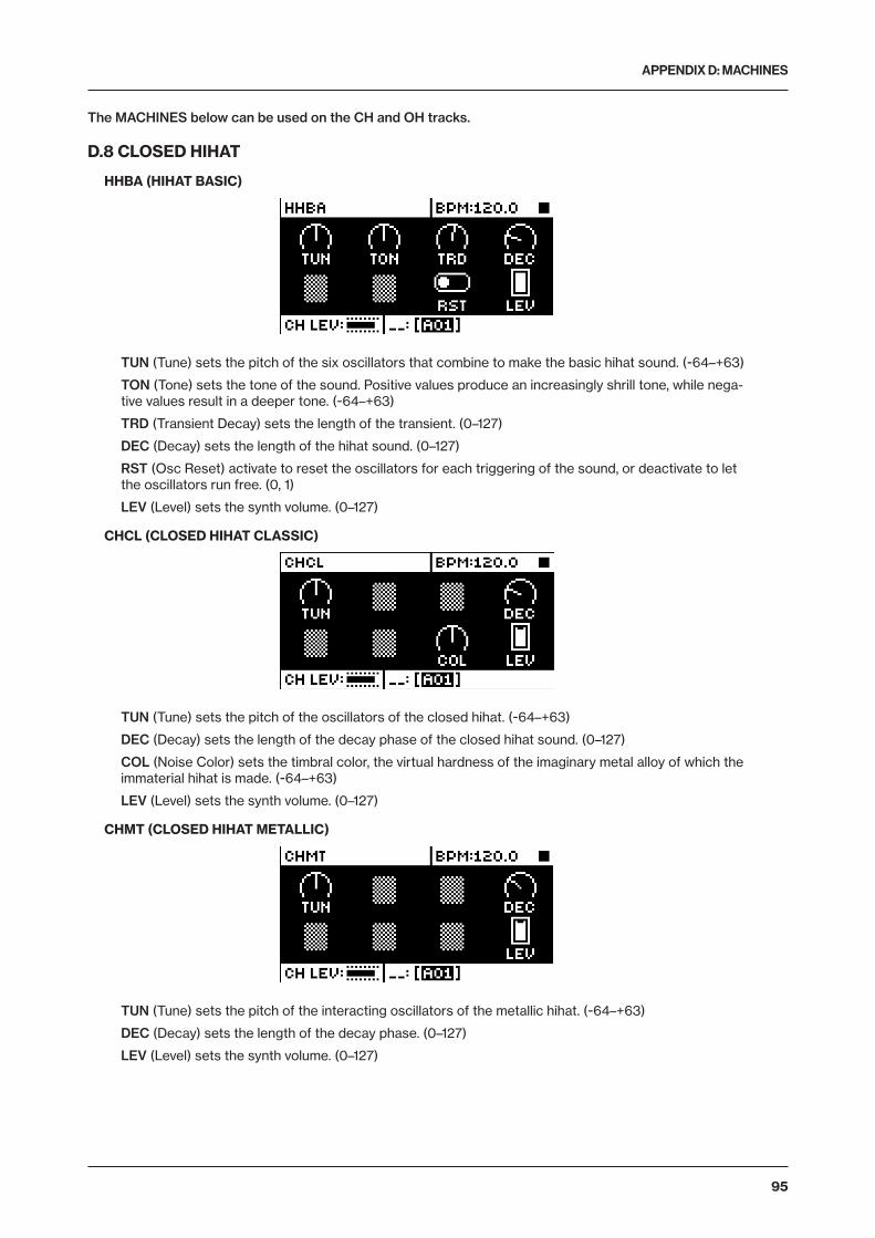
APPENDIX D: MACHINES
95
The MACHINES below can be used on the CH and OH tracks.
D.8 CLOSED HIHAT
HHBA (HIHAT BASIC)
TUN (Tune) sets the pitch of the six oscillators that combine to make the basic hihat sound. (-64–+63)
TON (Tone) sets the tone of the sound. Positive values produce an increasingly shrill tone, while nega-tive values result in a deeper tone. (-64–+63)
TRD (Transient Decay) sets the length of the transient. (0–127)
DEC (Decay) sets the length of the hihat sound. (0–127)
RST (Osc Reset) activate to reset the oscillators for each triggering of the sound, or deactivate to let the oscillators run free. (0, 1)
LEV (Level) sets the synth volume. (0–127)
CHCL (CLOSED HIHAT CLASSIC)
TUN (Tune) sets the pitch of the oscillators of the closed hihat. (-64–+63)
DEC (Decay) sets the length of the decay phase of the closed hihat sound. (0–127)
COL (Noise Color) sets the timbral color, the virtual hardness of the imaginary metal alloy of which the immaterial hihat is made. (-64–+63)
LEV (Level) sets the synth volume. (0–127)
CHMT (CLOSED HIHAT METALLIC)
TUN (Tune) sets the pitch of the interacting oscillators of the metallic hihat. (-64–+63)
DEC (Decay) sets the length of the decay phase. (0–127)
LEV (Level) sets the synth volume. (0–127)
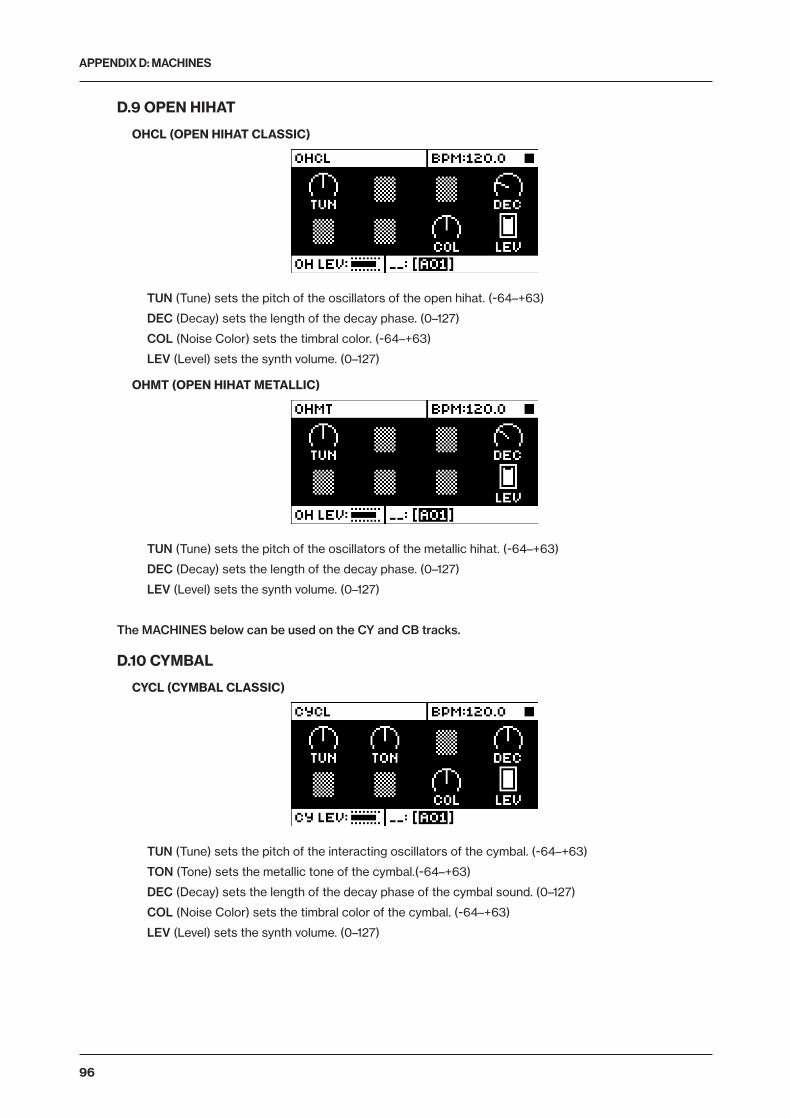
APPENDIX D: MACHINES
96
D.9 OPEN HIHAT
OHCL (OPEN HIHAT CLASSIC)
TUN (Tune) sets the pitch of the oscillators of the open hihat. (-64–+63)
DEC (Decay) sets the length of the decay phase. (0–127)
COL (Noise Color) sets the timbral color. (-64–+63)
LEV (Level) sets the synth volume. (0–127)
OHMT (OPEN HIHAT METALLIC)
TUN (Tune) sets the pitch of the oscillators of the metallic hihat. (-64–+63)
DEC (Decay) sets the length of the decay phase. (0–127)
LEV (Level) sets the synth volume. (0–127)
The MACHINES below can be used on the CY and CB tracks.
D.10 CYMBAL
CYCL (CYMBAL CLASSIC)
TUN (Tune) sets the pitch of the interacting oscillators of the cymbal. (-64–+63)
TON (Tone) sets the metallic tone of the cymbal.(-64–+63)
DEC (Decay) sets the length of the decay phase of the cymbal sound. (0–127)
COL (Noise Color) sets the timbral color of the cymbal. (-64–+63)
LEV (Level) sets the synth volume. (0–127)
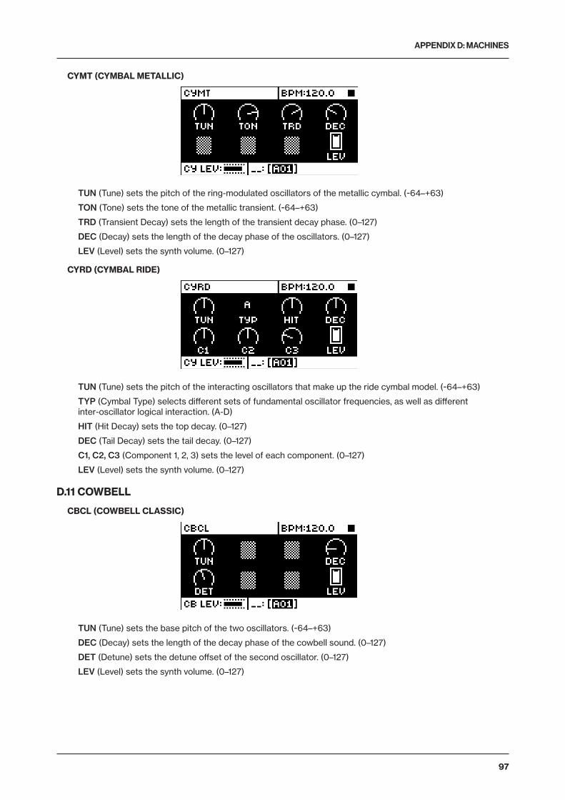
APPENDIX D: MACHINES
97
CYMT (CYMBAL METALLIC)
TUN (Tune) sets the pitch of the ring-modulated oscillators of the metallic cymbal. (-64–+63)
TON (Tone) sets the tone of the metallic transient. (-64–+63)
TRD (Transient Decay) sets the length of the transient decay phase. (0–127)
DEC (Decay) sets the length of the decay phase of the oscillators. (0–127)
LEV (Level) sets the synth volume. (0–127)
CYRD (CYMBAL RIDE)
TUN (Tune) sets the pitch of the interacting oscillators that make up the ride cymbal model. (-64–+63)
TYP (Cymbal Type) selects different sets of fundamental oscillator frequencies, as well as different inter-oscillator logical interaction. (A-D)
HIT (Hit Decay) sets the top decay. (0–127)
DEC (Tail Decay) sets the tail decay. (0–127)
C1, C2, C3 (Component 1, 2, 3) sets the level of each component. (0–127)
LEV (Level) sets the synth volume. (0–127)
D.11 COWBELL
CBCL (COWBELL CLASSIC)
TUN (Tune) sets the base pitch of the two oscillators. (-64–+63)
DEC (Decay) sets the length of the decay phase of the cowbell sound. (0–127)
DET (Detune) sets the detune offset of the second oscillator. (0–127)
LEV (Level) sets the synth volume. (0–127)

APPENDIX D: MACHINES
98
CBMT (COWBELL METALLIC)
TUN (Tune) sets the base pitch of the two oscillators. (-64–+63)
DEC (Decay) sets the length of the decay phase of the metallic cowbell sound. (0–127)
DET (Detune) sets the detune offset of the second oscillator. (0–127)
LEV (Level) sets the synth volume. (0–127)
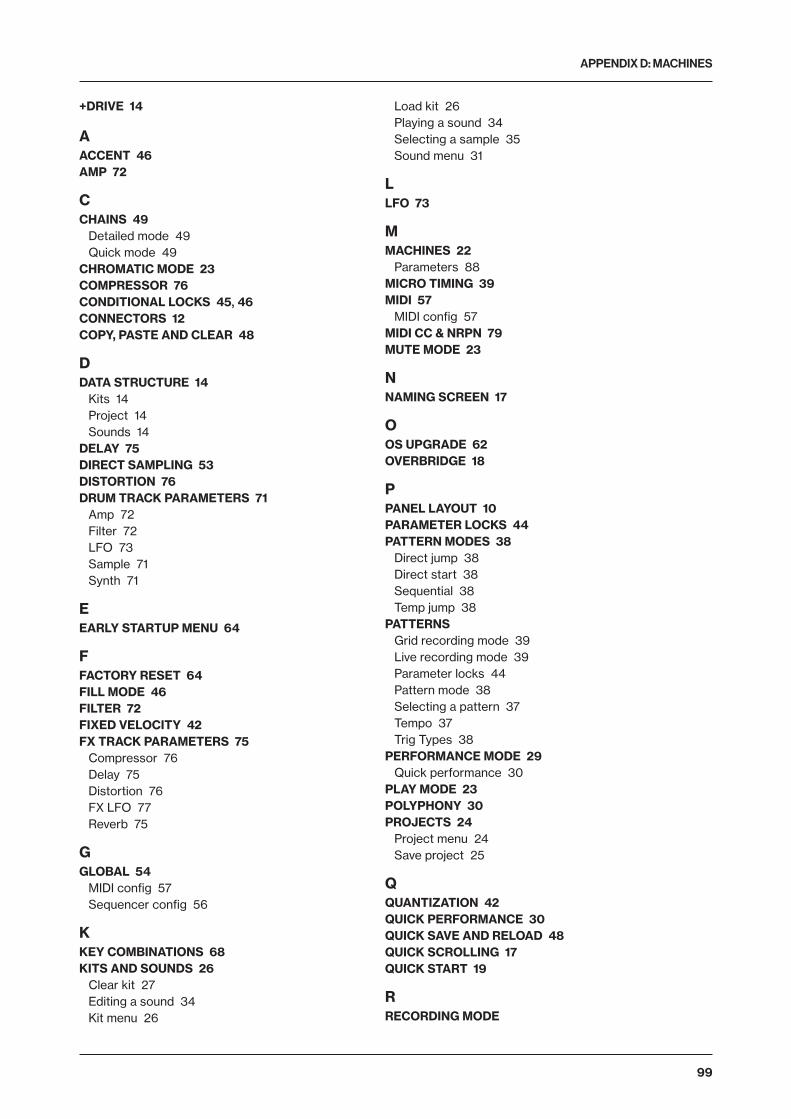
APPENDIX D: MACHINES
99
+DRIVE 14
AACCENT 46AMP 72
CCHAINS 49
Detailed mode 49Quick mode 49
CHROMATIC MODE 23COMPRESSOR 76CONDITIONAL LOCKS 45, 46CONNECTORS 12COPY, PASTE AND CLEAR 48
DDATA STRUCTURE 14
Kits 14Project 14Sounds 14
DELAY 75DIRECT SAMPLING 53DISTORTION 76DRUM TRACK PARAMETERS 71
Amp 72Filter 72LFO 73Sample 71Synth 71
EEARLY STARTUP MENU 64
FFACTORY RESET 64FILL MODE 46FILTER 72FIXED VELOCITY 42FX TRACK PARAMETERS 75
Compressor 76Delay 75Distortion 76FX LFO 77Reverb 75
GGLOBAL 54
MIDI config 57Sequencer config 56
KKEY COMBINATIONS 68KITS AND SOUNDS 26
Clear kit 27Editing a sound 34Kit menu 26
Load kit 26Playing a sound 34Selecting a sample 35Sound menu 31
LLFO 73
MMACHINES 22
Parameters 88MICRO TIMING 39MIDI 57
MIDI config 57MIDI CC & NRPN 79MUTE MODE 23
NNAMING SCREEN 17
OOS UPGRADE 62OVERBRIDGE 18
PPANEL LAYOUT 10PARAMETER LOCKS 44PATTERN MODES 38
Direct jump 38Direct start 38Sequential 38Temp jump 38
PATTERNSGrid recording mode 39Live recording mode 39Parameter locks 44Pattern mode 38Selecting a pattern 37Tempo 37Trig Types 38
PERFORMANCE MODE 29Quick performance 30
PLAY MODE 23POLYPHONY 30PROJECTS 24
Project menu 24Save project 25
QQUANTIZATION 42QUICK PERFORMANCE 30QUICK SAVE AND RELOAD 48QUICK SCROLLING 17QUICK START 19
RRECORDING MODE

APPENDIX D: MACHINES
100
Grid recording mode 39RECORDING MODES
Live recording mode 39REVERB 75
SSAFETY AND MAINTENANCE 3SAMPLE
Loading, unloading, replacing 54SAMPLES 54
Create a new destination directory 56Receiving from computer 55
SAMPLING 52Direct sampling 53Sampling audio 53
SCALE SETUPAdvanced mode 44Normal mode 43
SCENE MODE 28SEQUENCER 37
Accent 46Click track 43Conditional locks 45Editing a pattern 38Parameter locks 44Pattern control 37Pattern menu 41Pattern modes 38Retrig menu 39Scale menu 43Selecting a pattern 37Sound locks 45Swing 42, 47Track menu 40Trig menu 41Trig mute 46
SETUP EXAMPLES 65Analog Rytm with a monophonic bass machine 65Analog Rytm with other Elektron gear 66Analog Rytm with stereophonic drum machine 65
SONGS 49SOUND ARCHITECTURE 13SOUND BROWSER 31SOUND LOCKS 45SOUND MANAGER 32SOUNDS
Clear sound 33Editing a Sound 34Playing a Sound 34Rename Sound 33
SPECIFICATIONS 70SWING 42, 47SYSEX
Sysex receive 61Sysex send 60
TTECHNICAL INFORMATION 70TEMPO
Tap tempo 38Tempo nudge 38
TRACK ROUTINGGlobal 59Kit 27
TRIG MENU 41TRIG MUTE 46TRIGS
Lock trig 38Note 38Parameter lock 44Sound lock 45Trig mute 46
UUSER INTERFACE 16
VVOICE CIRCUITS 13


826
2EN
G-A