Embed Size (px)
Citation preview
Claplight MKII
Service Kring JOTA-JOTI
www.kitbuilding.org
Page 1 of 12
Version 01-04-2017
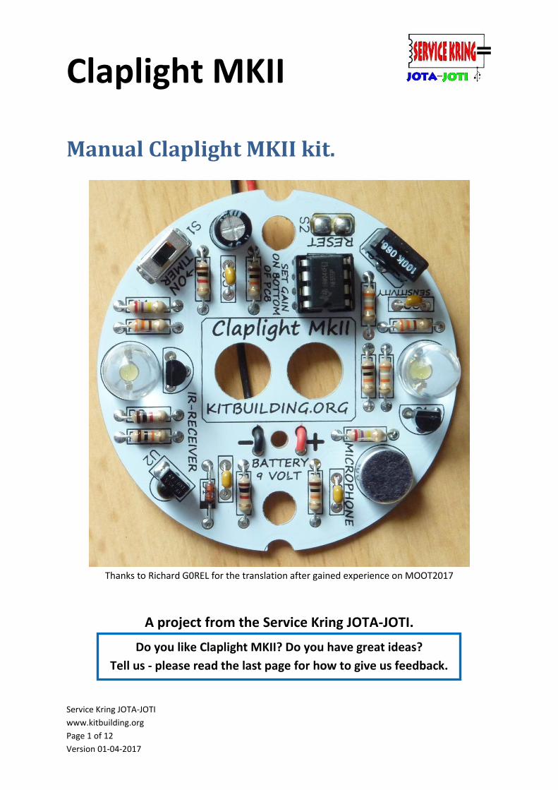
Manual Claplight MKII kit.
Thanks to Richard G0REL for the translation after gained experience on MOOT2017
A project from the Service Kring JOTA-JOTI.
Do you like Claplight MKII? Do you have great ideas?
Tell us - please read the last page for how to give us feedback.
Claplight MKII
Service Kring JOTA-JOTI
www.kitbuilding.org
Page 2 of 12
Version 01-04-2017
Manual Claplight MKII kit. ....................................................................................................................... 1
Remarks ................................................................................................................................................... 2
The Claplight MKII: .................................................................................................................................. 3
Usage ....................................................................................................................................................... 3
Content of the package: .......................................................................................................................... 4
Component Numbering and component values: .................................................................................... 5
Construction description of the Claplight MKII: ..................................................................................... 5
Mounting Sequence ............................................................................................................................ 6
The use and adjustment of the Claplight MKII: ....................................................................................... 8
Set Sensitivity Range: .......................................................................................................................... 8
Operation: ........................................................................................................................................... 8
Adjustment of the sensitivity: ............................................................................................................. 8
Usage: .................................................................................................................................................. 8
Schematic : .............................................................................................................................................. 9
Component assembly and solder side: ................................................................................................. 10
Complete ready build board : ................................................................................................................ 11
Soldering with children: ........................................................................................................................ 12
Feedback: .............................................................................................................................................. 12
Remarks
Unlike previous years, all the documentation for the kit is included in one big document. This keeps
all the background information and other information together, apart from the construction
description.
We advise you to read this entire document carefully. It is sufficient to print only pages 6 and 7 for
the purpose of building it. During construction, it can also be convenient to have page 8 on hand, as a
quick reference.
TIP: Build one kit yourself before JOTA. Besides being fun, it is also informative.
Claplight MKII
Service Kring JOTA-JOTI
www.kitbuilding.org
Page 3 of 12
Version 01-04-2017
We are very pleased that It appears that the solder activities are not only limited to the JOTA-JOTI
minded people, but also for use at group -weekends, international camps and schools activities.
Because of the continuing demand for the Claplight and other simple electronics kits, we facelifted
the famous and popular Claplight 2009 with a new look.
The Claplight MKII:
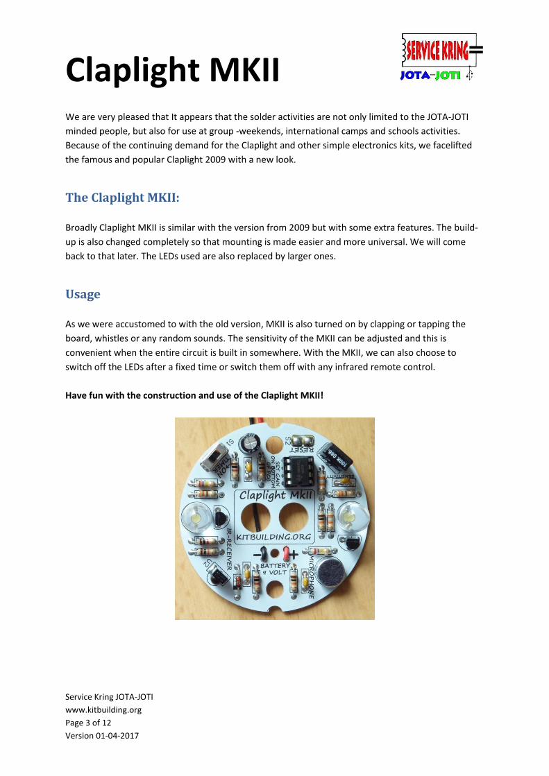
Broadly Claplight MKII is similar with the version from 2009 but with some extra features. The build-
up is also changed completely so that mounting is made easier and more universal. We will come
back to that later. The LEDs used are also replaced by larger ones.
Usage
As we were accustomed to with the old version, MKII is also turned on by clapping or tapping the
board, whistles or any random sounds. The sensitivity of the MKII can be adjusted and this is
convenient when the entire circuit is built in somewhere. With the MKII, we can also choose to
switch off the LEDs after a fixed time or switch them off with any infrared remote control.
Have fun with the construction and use of the Claplight MKII!
Claplight MKII
Service Kring JOTA-JOTI
www.kitbuilding.org
Page 4 of 12
Version 01-04-2017
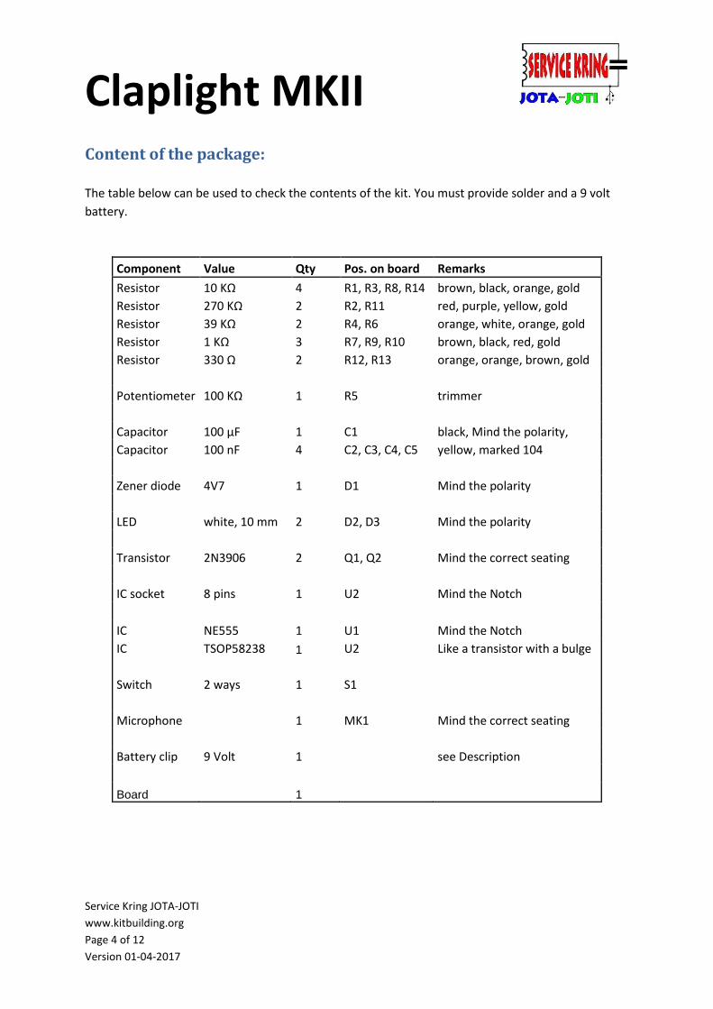
Content of the package:
The table below can be used to check the contents of the kit. You must provide solder and a 9 volt
battery.
Component Value Qty Pos. on board Remarks
Resistor 10 KΩ 4 R1, R3, R8, R14 brown, black, orange, gold
Resistor 270 KΩ 2 R2, R11 red, purple, yellow, gold
Resistor 39 KΩ 2 R4, R6 orange, white, orange, gold
Resistor 1 KΩ 3 R7, R9, R10 brown, black, red, gold
Resistor 330 Ω 2 R12, R13 orange, orange, brown, gold
Potentiometer 100 KΩ 1 R5 trimmer
Capacitor 100 µF 1 C1 black, Mind the polarity,
Capacitor 100 nF 4 C2, C3, C4, C5 yellow, marked 104
Zener diode 4V7 1 D1 Mind the polarity
LED white, 10 mm 2 D2, D3 Mind the polarity
Transistor 2N3906 2 Q1, Q2 Mind the correct seating
IC socket 8 pins 1 U2 Mind the Notch
IC NE555 1 U1 Mind the Notch
IC TSOP58238 1 U2 Like a transistor with a bulge
Switch 2 ways 1 S1
Microphone 1 MK1 Mind the correct seating
Battery clip 9 Volt 1 see Description
Board 1
Claplight MKII
Service Kring JOTA-JOTI
www.kitbuilding.org
Page 5 of 12
Version 01-04-2017
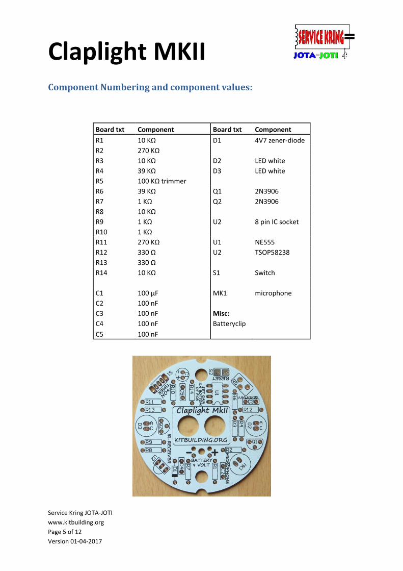
Component Numbering and component values:
Board txt Component Board txt Component
R1 10 KΩ D1 4V7 zener-diode
R2 270 KΩ
R3 10 KΩ D2 LED white
R4 39 KΩ D3 LED white
R5 100 KΩ trimmer
R6 39 KΩ Q1 2N3906
R7 1 KΩ Q2 2N3906
R8 10 KΩ
R9 1 KΩ U2 8 pin IC socket
R10 1 KΩ
R11 270 KΩ U1 NE555
R12 330 Ω U2 TSOP58238
R13 330 Ω
R14 10 KΩ S1 Switch
C1 100 µF MK1 microphone
C2 100 nF
C3 100 nF Misc:
C4 100 nF Batteryclip
C5 100 nF
Claplight MKII
Service Kring JOTA-JOTI
www.kitbuilding.org
Page 6 of 12
Version 01-04-2017
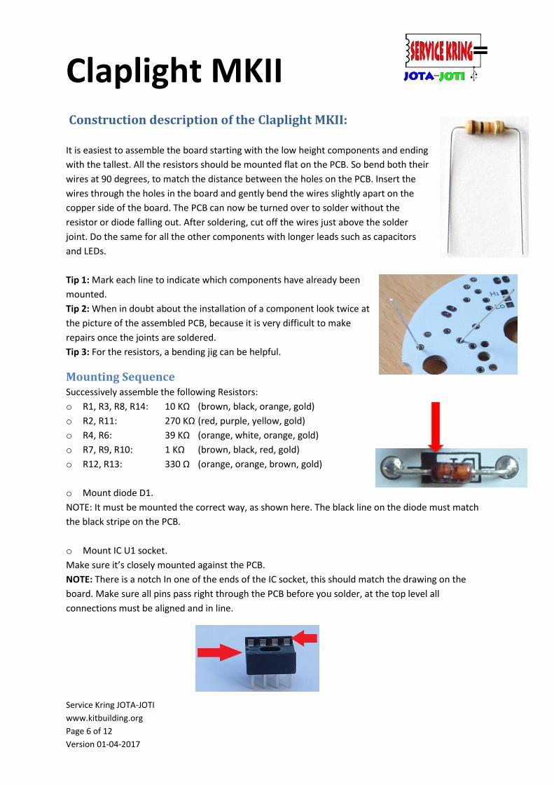
Construction description of the Claplight MKII:
It is easiest to assemble the board starting with the low height components and ending
with the tallest. All the resistors should be mounted flat on the PCB. So bend both their
wires at 90 degrees, to match the distance between the holes on the PCB. Insert the
wires through the holes in the board and gently bend the wires slightly apart on the
copper side of the board. The PCB can now be turned over to solder without the
resistor or diode falling out. After soldering, cut off the wires just above the solder
joint. Do the same for all the other components with longer leads such as capacitors
and LEDs.
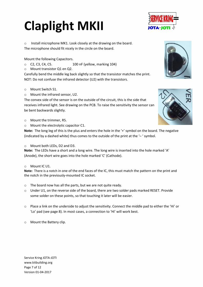
Tip 1: Mark each line to indicate which components have already been
mounted.
Tip 2: When in doubt about the installation of a component look twice at
the picture of the assembled PCB, because it is very difficult to make
repairs once the joints are soldered.
Tip 3: For the resistors, a bending jig can be helpful.
Mounting Sequence Successively assemble the following Resistors:
o R1, R3, R8, R14: 10 KΩ (brown, black, orange, gold)
o R2, R11: 270 KΩ (red, purple, yellow, gold)
o R4, R6: 39 KΩ (orange, white, orange, gold)
o R7, R9, R10: 1 KΩ (brown, black, red, gold)
o R12, R13: 330 Ω (orange, orange, brown, gold)
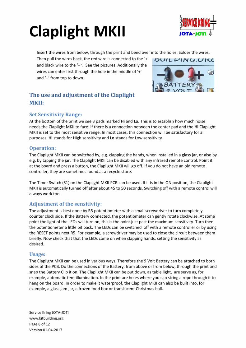
o Mount diode D1.
NOTE: It must be mounted the correct way, as shown here. The black line on the diode must match
the black stripe on the PCB.
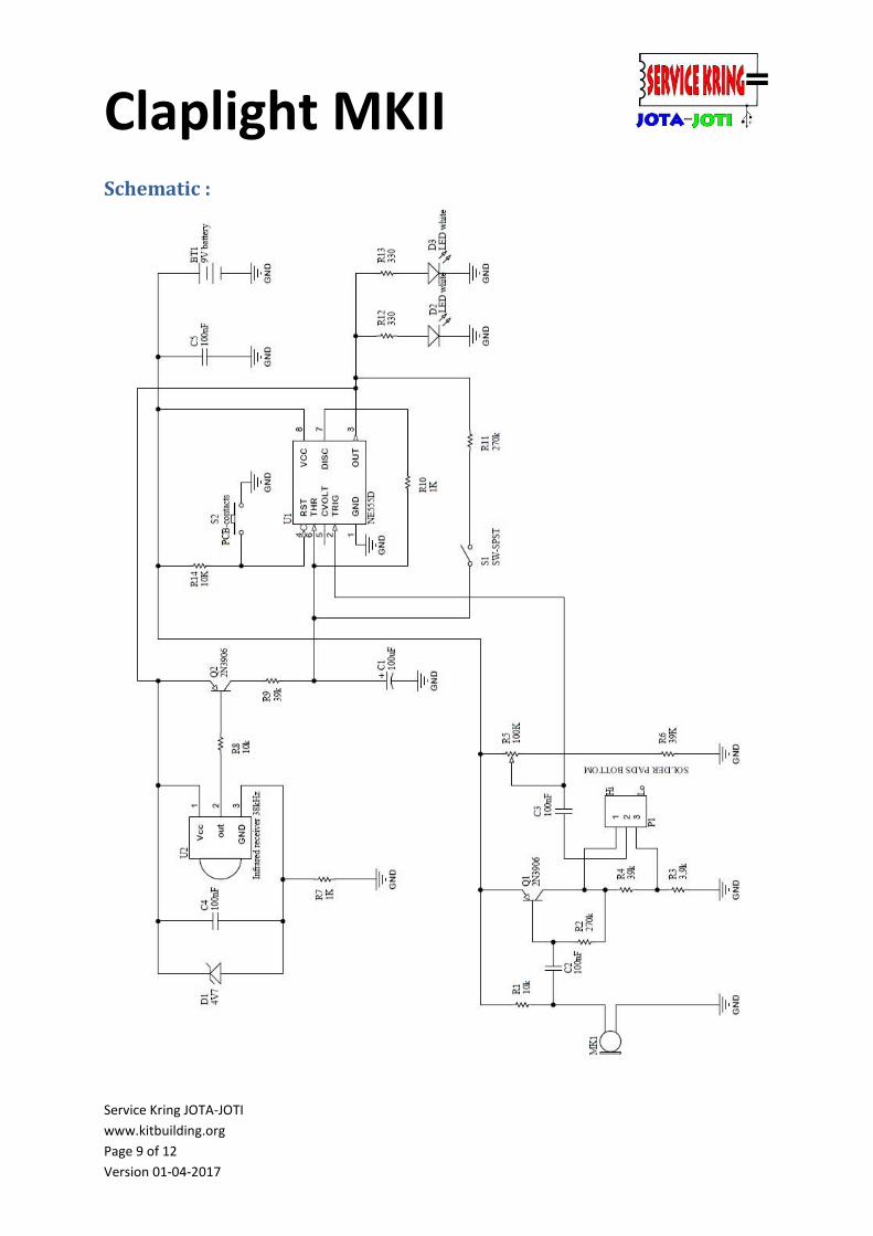
o Mount IC U1 socket.
Make sure it’s closely mounted against the PCB.
NOTE: There is a notch In one of the ends of the IC socket, this should match the drawing on the
board. Make sure all pins pass right through the PCB before you solder, at the top level all
connections must be aligned and in line.
Claplight MKII
Service Kring JOTA-JOTI
www.kitbuilding.org
Page 7 of 12
Version 01-04-2017
o Install microphone MK1. Look closely at the drawing on the board.
The microphone should fit nicely in the circle on the board.
Mount the following Capacitors.
o C2, C3, C4, C5. 100 nF (yellow, marking 104) o Mount transistor Q1 en Q2.
Carefully bend the middle leg back slightly so that the transistor matches the print.
NOT: Do not confuse the infrared detector (U2) with the transistors.
o Mount Switch S1.
o Mount the infrared sensor, U2.
The convex side of the sensor is on the outside of the circuit, this is the side that
receives infrared light. See drawing on the PCB. To raise the sensitivity the sensor can
be bent backwards slightly.
o Mount the trimmer, R5.
o Mount the electrolytic capacitor C1.
Note: The long leg of this is the plus and enters the hole in the ’+’ symbol on the board. The negative
(indicated by a dashed white) thus comes to the outside of the print at the ‘– ‘ symbol.
o Mount both LEDs, D2 and D3. Note: The LEDs have a short and a long wire. The long wire is inserted into the hole marked ‘A’
(Anode), the short wire goes into the hole marked ‘C’ (Cathode).
o Mount IC U1. Note: There is a notch in one of the end faces of the IC, this must match the pattern on the print and the notch in the previously-mounted IC socket.
o The board now has all the parts, but we are not quite ready.
o Under U1, on the reverse side of the board, there are two solder pads marked RESET. Provide
some solder on these points, so that touching it later will be easier.
o Place a link on the underside to adjust the sensitivity. Connect the middle pad to either the ‘Hi’ or
‘Lo’ pad (see page 8). In most cases, a connection to ‘Hi’ will work best.
o Mount the Battery clip.
Claplight MKII
Service Kring JOTA-JOTI
www.kitbuilding.org
Page 8 of 12
Version 01-04-2017
Insert the wires from below, through the print and bend over into the holes. Solder the wires.
Then pull the wires back, the red wire is connected to the ‘+‘
and black wire to the ‘– ‘. See the pictures. Additionally the
wires can enter first through the hole in the middle of ‘+’
and ‘–‘ from top to down.
The use and adjustment of the Claplight
MKII:
Set Sensitivity Range: At the bottom of the print we see 3 pads marked Hi and Lo. This is to establish how much noise needs the Claplight MKII to face. If there is a connection between the center pad and the Hi Claplight MKII is set to the most sensitive range. In most cases, this connection will be satisfactory for all purposes. Hi stands for High sensitivity and Lo stands for Low sensitivity.
Operation: The Claplight MKII can be switched by, e.g. clapping the hands, when installed in a glass jar, or also by e.g. by tapping the jar. The Claplight MKII can be disabled with any infrared remote control. Point it at the board and press a button, the Claplight MKII will go off. If you do not have an old remote controller, they are sometimes found at a recycle store. The Timer Switch (S1) on the Claplight MKII PCB can be used. If it is in the ON position, the Claplight MKII is automatically turned off after about 45 to 50 seconds. Switching off with a remote control will always work too.
Adjustment of the sensitivity: The adjustment is best done by R5 potentiometer with a small screwdriver to turn completely counter clock side. If the Battery connected, the potentiometer can gently rotate clockwise. At some point the light of the LEDs will turn on, this is the point just past the maximum sensitivity. Turn then the potentiometer a little bit back. The LEDs can be switched off with a remote controller or by using the RESET points next R5. For example, a screwdriver may be used to close the circuit between them briefly. Now check that that the LEDs come on when clapping hands, setting the sensitivity as desired.
Usage: The Claplight MKII can be used in various ways. Therefore the 9 Volt Battery can be attached to both sides of the PCB. Do the connections of the Battery, from above or from below, through the print and snap the Battery Clip it on. The Claplight MKII can be put down, as table light, are serve as, for example, automatic tent illumination. In the print are holes where you can string a rope through it to hang on the board. In order to make it waterproof, the Claplight MKII can also be built into, for example, a glass jam jar, a frozen food box or translucent Christmas ball.
Claplight MKII
Service Kring JOTA-JOTI
www.kitbuilding.org
Page 9 of 12
Version 01-04-2017
Schematic :
Claplight MKII
Service Kring JOTA-JOTI
www.kitbuilding.org
Page 10 of 12
Version 01-04-2017
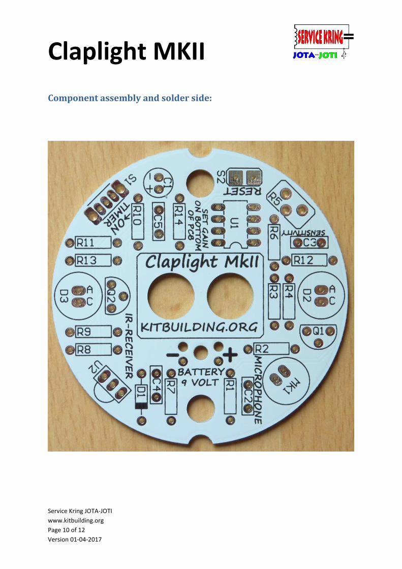
Component assembly and solder side:
Claplight MKII
Service Kring JOTA-JOTI
www.kitbuilding.org
Page 11 of 12
Version 01-04-2017
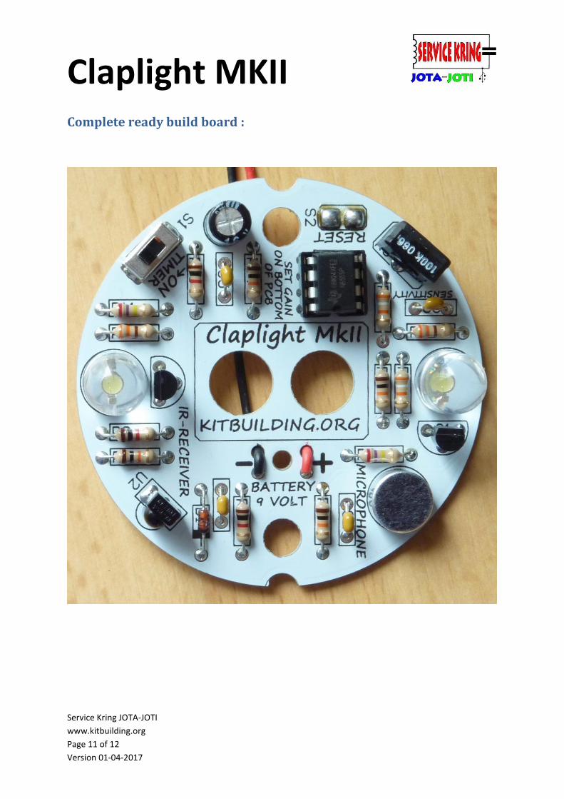
Complete ready build board :
Claplight MKII
Service Kring JOTA-JOTI
www.kitbuilding.org
Page 12 of 12
Version 01-04-2017
Soldering with children:
There are some pitfalls when soldering with children. By avoiding these, it is likely that the new little
project can be completed successfully.
In the field, we see the following problems:
• The making of the soldered connection takes (much) too long, a good soldered connection is made
in about 3 seconds. Approximately 1.5 seconds for pre-heat (with a little solder to the tip for good
heat conduction), attach solder, solder and remove the soldering iron. Children do not have this skill
yet and the materials are heated for too long and thus too hot.
• Children often tend to put solder on the soldering iron and then "stick" the solder on the board, the
flux is already burning and poor soldering is the result. In an attempt to get it right, the solder
connection heats up too long, causing component failures, etc.
• Temperature-controlled soldering irons are set at too high a temperature, for leaded solder around
320°C is a good temperature for soldering.
• NON-controlled soldering irons often have too high power and the bit temperature can reach 450 -
500 °C. An iron with a power of about 15 to 20 W is the most suitable for these boards.
• The assistant has previously not read the manual and do not know exactly what to do.
• There is too little guidance in relation to the number of participants. Certainly the youngest
children, many need much guidance. Aim for one attendant per Beaver and with Cubs / Gnomes one
supervisor per soldering station (2 children). With older Scouts, go for one supervisor for four
members. If the members are more experienced this can be adjusted of course.
• Besides the guidance soldering, it is advisable to have one supervisor who checks the PCB with the
components mounted on it before soldering and (if applicable) places the ICs, etc. This trouble-
shooter can also look at mal-functioning PCBs that do not work right away.
Feedback:
Do you have comments or would like to give your feedback about the Claplight?
Do you have comments or questions about the Service Kring JOTA-JOTI?
Please contact us via the contact form on the site www.kitbuilding.org
On behalf of the Service Kring JOTA-JOTI, we wish everyone a lot of fun building but also enjoy the
Claplight MKII