Embed Size (px)
Citation preview

Technical University of Crete
Thesis
An Application for Controlling aWireless Sensor Network Using a
Smartphone
Author:
Costas Zarifis
Examination Committee:
(Supervisor) Prof. Antonios Deligiannakis
Prof. Aggelos Bletsas
Prof. Minos Garofalakis
A thesis submitted in fulfillment of the requirements
for the degree of Bachelor in Electronic and Computer Engineering
in
Department of Electronic and Computer Engineering
May 20, 2013
ΠΟΛΥΤΕΧΝΕΙΟ ΚΡΗΤΗΣ
ΔΙΠΛΩΜΑΤΙΚΗ ΕΡΓΑΣΙΑ
Εφαρμογή Χειρισμού ΑσύρματουΔικτύου Αισθητήρων με Χρήση ενός
Smartphone
Συγγραφέας:
Κώστας Ζαρίφης
Εξεταστική Επιτροπή:
(Επιβλέπων) Καθ. Αντώνιος Δεληγιαννάκης
Καθ. ΄Αγγελος Μπλέτσας
Καθ. Μίνως Γαροφαλάκης
Εκπόνηση διπλωματικής εργασίας προς ολοκήρωση των προπτυχιακών σπουδών του
τμήματος
Ηλεκτρονικών Μηχανικών και Μηχανικών Υπολογιστών
20 Μαΐου 2013

“Talk is cheap. Show me the code.”
Linus Torvalds

TECHNICAL UNIVERSITY OF CRETE
Abstract
Softnet
Department of Electronic and Computer Engineering
Bachelor in Electronic and Computer Engineering
An Application for Controlling a Wireless Sensor Network Using a
Smartphone
by Costas Zarifis
The use of smartphone devices over the past years seems to follow a growing trend.
This great acceptance along with the endless possibilities that go hand to hand with
having a mini computer at all times within reach, can explain this vast interest shown
by solo developers and major companies in the mobile industry. As a result, many
innovative applications roll out daily to the various online stores, making the lives of the
smartphone users a lot better. This thesis describes the design and implementation of
a mobile app, a Web Service and a TinyOS application, that bind together allowing the
user to execute a variety of queries on a sensor network from any place in the world.
Until now, the user of a sensor network was usually constrained to be in the same room
or area in which the network was installed, in order to execute a query and receive the
measurements retrieved by the sensors or to detect outlier measurements from motes.
Although nowadays there are various programs that enable users to operate a sensor
network, they do not effectively resolve some issues that arise. Many of these programs
do in fact have a graphical user interface (GUI) that allows the users to operate on it,
but it is usually somewhat outdated and abstract. As a result the user can easily get
confused while using it. Additionally, since they have not received any major updates
recently, they usually cannot run on modern operating systems and more importantly,
they can only run on conventional computers and not on mobile devices.
The user of the mobile application developed as a part of this Thesis on the other hand,
can operate a Wireless Sensor Network (WSN) without the aforementioned limitations.
The user-interface of this app is simple and easy to use, following the trends set by
Google and other major companies. Additionally, since this is a mobile application, the
user can use it while on the go, without geographical restrictions. He could be in the
same room where the sensors are installed, or in an entirely different continent and still
be able to use the sensor network, as long as there is internet access.
Mobile applications certainly have many advantages over applications that are intended
to run on desktops or laptops but they also come with some restrictions. The limited
battery life that the majority of these devices have, is without a doubt the most
important concern for a developer. Big screens with high resolution may be easier
to view and operate on (not to mention impressive), considering the fact that almost
every single smartphone produced today comes with a touch screen, but it has a big
impact on the battery life. The same applies to radio usage. Wi-Fi and 3G-4G networks
can drain the battery within a few minutes of heavy traffic. The mobile app developer
should also keep in mind that even if the majority of these device have a respectable
processing power for a mobile device, it really is no match for the processing power
of conventional desktops and laptops. Additionally, the fact that these smartphones
support multitasking can affect even more the already limited processing power. What
multitasking means is that other processes are executed simultaneously. As a result other
processes may use the same resources our application uses. It is therefore important to
develop applications that do not overuse the provided resources, as this may cause
problems to other applications running on the background.
More or less the same principles apply when developing the applications run on the
sensor network. While the Operating System used by the motes is fairly lightweight
and the CPU as the rest of the hardware configuration does not seem to be very power
consuming, it is important for the developer to keep in mind that he should find ways to
keep radio and CPU usage to the minimum. Furthermore, these devices have a limited
flash memory which means that the produced executable file has to be relatively small
as well.
Last but not least, in order for the before-mentioned parts to tie together, a web service
had to be implemented. The client, which in this case is the mobile application, interacts
with the mote network using internet access. In order for this to be possible the client
should first interact with a web service that ”listens to” a specific public internet address,
which in turn interacts with the mote network. Basically, the role of the web service is
to disseminate messages between the mobile app and the sensor network and to keep
track of the activities that take place.

Acknowledgements
First of all, I would like to thank my Thesis supervisor Prof. Antonios Deligiannakis for
his continuous inspiration, support, and trust during our cooperation. I would also like
to thank the members of the examination committee Prof. Aggelos Bletsas and Prof.
Minos Garofalakis.
Furthermore, I would like to thank from the bottom of my heart Antonios Igglezakis,
who did an amazing work on his outlier detection application, which he let me integrate
into my Thesis. His assistance was more than helpful and his patience is certainly one
of his most valuable virtues.
In addition, I want to thank my friends for their moral support and their belief in me
for the past years, and of course for being there for me during the times I needed them
the most. I’m really honored to have met you guys and I wish you nothing but the best!
Last but not least, I can’t find the words to describe the help, support and never-
ending love I receive daily from my beloved family, not to mention their patience and
understanding over the past few years.
Costas Zarifis
Technical University of Crete
May 2013
iv
Contents
Abstract ii
Acknowledgements iv
List of Figures viii
1 Introduction 1
1.1 Mobile Industry and Mobile Software Development . . . . . . . . . . . . . 1
1.2 Sensor Network and TinyOS . . . . . . . . . . . . . . . . . . . . . . . . . . 2
1.3 Web Services . . . . . . . . . . . . . . . . . . . . . . . . . . . . . . . . . . 3
1.4 Thesis Contribution . . . . . . . . . . . . . . . . . . . . . . . . . . . . . . 4
2 Architecture 6
2.1 Client-Server Model . . . . . . . . . . . . . . . . . . . . . . . . . . . . . . 6
2.1.1 Two-Tier Architecture . . . . . . . . . . . . . . . . . . . . . . . . . 7
2.1.2 Multitier Architecture (N-Tier Architecture) . . . . . . . . . . . . 9
2.1.3 Error Handling . . . . . . . . . . . . . . . . . . . . . . . . . . . . . 10
2.2 Model View Controller (MVC) . . . . . . . . . . . . . . . . . . . . . . . . 11
2.3 Comparison Between Three-tier and MVC Architecture . . . . . . . . . . 11
2.4 N-Tier Architecture in this Implementation . . . . . . . . . . . . . . . . . 12
2.5 Integrated Development Environments (IDE) . . . . . . . . . . . . . . . . 14
2.5.1 NetBeans IDE . . . . . . . . . . . . . . . . . . . . . . . . . . . . . 15
2.5.2 Eclipse IDE . . . . . . . . . . . . . . . . . . . . . . . . . . . . . . . 15
2.6 Software Development Kit (SDK) . . . . . . . . . . . . . . . . . . . . . . . 16
2.7 Mobile Architectures . . . . . . . . . . . . . . . . . . . . . . . . . . . . . . 16
2.7.1 Platforms . . . . . . . . . . . . . . . . . . . . . . . . . . . . . . . . 17
2.7.2 ARM Architecture . . . . . . . . . . . . . . . . . . . . . . . . . . . 17
2.7.2.1 RISC architecture . . . . . . . . . . . . . . . . . . . . . . 17
2.7.2.2 ARM vs Intel . . . . . . . . . . . . . . . . . . . . . . . . . 18
2.7.3 Mobile Development . . . . . . . . . . . . . . . . . . . . . . . . . . 19
2.7.4 Android Development . . . . . . . . . . . . . . . . . . . . . . . . . 21
2.7.4.1 Activity Lifecycle . . . . . . . . . . . . . . . . . . . . . . 21
2.7.4.2 Screen Sizes in Android . . . . . . . . . . . . . . . . . . . 23
2.7.4.3 Different Platform Versions . . . . . . . . . . . . . . . . . 24
2.8 Web Services . . . . . . . . . . . . . . . . . . . . . . . . . . . . . . . . . . 25
2.8.1 SOAP Based Web Services . . . . . . . . . . . . . . . . . . . . . . 25
v

Contents vi
2.8.1.1 RPC . . . . . . . . . . . . . . . . . . . . . . . . . . . . . 26
2.8.1.2 Document Transmission . . . . . . . . . . . . . . . . . . . 27
2.8.1.3 The Structure of a SOAP Message . . . . . . . . . . . . . 28
2.8.1.4 The SOAP Message Path . . . . . . . . . . . . . . . . . . 30
2.8.2 RESTful Web Services . . . . . . . . . . . . . . . . . . . . . . . . . 30
2.8.3 REST vs SOAP . . . . . . . . . . . . . . . . . . . . . . . . . . . . 32
2.8.4 (Un)Marshalling . . . . . . . . . . . . . . . . . . . . . . . . . . . . 33
2.9 TinyOS Architecture . . . . . . . . . . . . . . . . . . . . . . . . . . . . . . 35
2.9.1 Interfaces . . . . . . . . . . . . . . . . . . . . . . . . . . . . . . . . 36
2.9.2 Modules & Configurations . . . . . . . . . . . . . . . . . . . . . . . 36
2.9.3 Singletons & Generic Components . . . . . . . . . . . . . . . . . . 36
2.9.4 Events & Tasks . . . . . . . . . . . . . . . . . . . . . . . . . . . . . 37
3 Requirements Analysis, User Interface Prototyping and Evaluation 38
3.1 Introduction . . . . . . . . . . . . . . . . . . . . . . . . . . . . . . . . . . . 38
3.2 Personas . . . . . . . . . . . . . . . . . . . . . . . . . . . . . . . . . . . . . 39
3.2.1 Anne, 41, Professor . . . . . . . . . . . . . . . . . . . . . . . . . . . 40
3.2.2 John, 63, Businessman . . . . . . . . . . . . . . . . . . . . . . . . . 41
3.2.3 Katia, 23, Undergraduate Student . . . . . . . . . . . . . . . . . . 42
3.3 Storyboarding . . . . . . . . . . . . . . . . . . . . . . . . . . . . . . . . . . 43
3.3.1 Receiving Feedback . . . . . . . . . . . . . . . . . . . . . . . . . . 47
3.4 Paper Prototyping . . . . . . . . . . . . . . . . . . . . . . . . . . . . . . . 48
3.5 Testing, Evaluation & Adjustments . . . . . . . . . . . . . . . . . . . . . 52
3.5.1 Cognitive Walkthrough . . . . . . . . . . . . . . . . . . . . . . . . 52
3.5.2 Think Aloud Method/Protocol . . . . . . . . . . . . . . . . . . . . 54
3.5.3 Adjustments . . . . . . . . . . . . . . . . . . . . . . . . . . . . . . 54
4 Sensor Network & TinyOS 56
4.1 Introduction . . . . . . . . . . . . . . . . . . . . . . . . . . . . . . . . . . . 56
4.2 Developing a TinyOS Application . . . . . . . . . . . . . . . . . . . . . . . 56
4.2.1 Simulating TinyOS Networks . . . . . . . . . . . . . . . . . . . . . 57
4.3 Power Consumption . . . . . . . . . . . . . . . . . . . . . . . . . . . . . . 62
4.4 TAG (Tiny AGgregation Service for Ad-Hoc Sensor Networks) . . . . . . 62
4.5 TiNA (A Scheme for Temporal Coherency-Aware in-Network Aggregation) 64
4.6 Description of Sensor Measurement TinyOS Application . . . . . . . . . . 64
4.6.1 Routing Phase . . . . . . . . . . . . . . . . . . . . . . . . . . . . . 64
4.6.2 Synchronization Phase . . . . . . . . . . . . . . . . . . . . . . . . . 66
4.6.3 Collection Phase . . . . . . . . . . . . . . . . . . . . . . . . . . . . 67
4.6.4 Ending Phase . . . . . . . . . . . . . . . . . . . . . . . . . . . . . . 67
4.7 Outlier Detection . . . . . . . . . . . . . . . . . . . . . . . . . . . . . . . . 68
4.7.1 The Geometric Approach . . . . . . . . . . . . . . . . . . . . . . . 68
4.8 Summary . . . . . . . . . . . . . . . . . . . . . . . . . . . . . . . . . . . . 68
5 Web Service 70
5.1 Introduction . . . . . . . . . . . . . . . . . . . . . . . . . . . . . . . . . . . 70
5.2 Choosing the Right Architecture & Framework . . . . . . . . . . . . . . . 70
5.3 JAX-WS . . . . . . . . . . . . . . . . . . . . . . . . . . . . . . . . . . . . . 71

Contents vii
5.4 XML Schema . . . . . . . . . . . . . . . . . . . . . . . . . . . . . . . . . . 83
5.5 Web Service - TinyOS Interaction . . . . . . . . . . . . . . . . . . . . . . 85
6 Database Design 87
6.1 Introduction . . . . . . . . . . . . . . . . . . . . . . . . . . . . . . . . . . . 87
6.2 Analysis of the Database Design . . . . . . . . . . . . . . . . . . . . . . . 88
6.2.1 User . . . . . . . . . . . . . . . . . . . . . . . . . . . . . . . . . . . 88
6.2.2 Session . . . . . . . . . . . . . . . . . . . . . . . . . . . . . . . . . 88
6.2.3 Measurements . . . . . . . . . . . . . . . . . . . . . . . . . . . . . 89
6.2.4 Edges . . . . . . . . . . . . . . . . . . . . . . . . . . . . . . . . . . 90
6.2.5 outliersEdges - outlierEdgesFinal . . . . . . . . . . . . . . . . . . . 90
6.2.6 Occupied . . . . . . . . . . . . . . . . . . . . . . . . . . . . . . . . 91
6.3 Relational Schema . . . . . . . . . . . . . . . . . . . . . . . . . . . . . . . 91
6.4 Summary . . . . . . . . . . . . . . . . . . . . . . . . . . . . . . . . . . . . 92
7 Android Application 93
7.1 Introduction . . . . . . . . . . . . . . . . . . . . . . . . . . . . . . . . . . . 93
7.2 Mobile Limitations . . . . . . . . . . . . . . . . . . . . . . . . . . . . . . . 93
7.3 Abstraction . . . . . . . . . . . . . . . . . . . . . . . . . . . . . . . . . . . 94
7.4 Blocking - Non blocking Operations . . . . . . . . . . . . . . . . . . . . . 94
7.4.1 Android’s AsyncTask . . . . . . . . . . . . . . . . . . . . . . . . . . 95
7.4.2 Android’s Background Service . . . . . . . . . . . . . . . . . . . . 97
7.5 Storage Option . . . . . . . . . . . . . . . . . . . . . . . . . . . . . . . . . 98
7.5.1 Shared Preferences . . . . . . . . . . . . . . . . . . . . . . . . . . . 98
7.5.2 Internal Storage . . . . . . . . . . . . . . . . . . . . . . . . . . . . 99
7.5.3 External Storage . . . . . . . . . . . . . . . . . . . . . . . . . . . . 99
7.5.4 SQLite Databases . . . . . . . . . . . . . . . . . . . . . . . . . . . 99
7.6 kSOAP2 . . . . . . . . . . . . . . . . . . . . . . . . . . . . . . . . . . . . . 100
7.7 User Interface . . . . . . . . . . . . . . . . . . . . . . . . . . . . . . . . . . 103
7.7.1 Android Layouts . . . . . . . . . . . . . . . . . . . . . . . . . . . . 103
7.7.2 Action Bar . . . . . . . . . . . . . . . . . . . . . . . . . . . . . . . 108
7.7.3 Canvas . . . . . . . . . . . . . . . . . . . . . . . . . . . . . . . . . 109
7.7.4 AChartEngine - A Charting Library for Android Applications . . . 113
7.8 Summary . . . . . . . . . . . . . . . . . . . . . . . . . . . . . . . . . . . . 117
8 Conclusion 119
8.1 Summary . . . . . . . . . . . . . . . . . . . . . . . . . . . . . . . . . . . . 119
8.2 Future Work . . . . . . . . . . . . . . . . . . . . . . . . . . . . . . . . . . 121
8.2.1 Web Application . . . . . . . . . . . . . . . . . . . . . . . . . . . . 121
8.2.2 Limit Bandwidth - Use Cache . . . . . . . . . . . . . . . . . . . . . 121
8.2.3 Additional Functionality for the Sensor Network . . . . . . . . . . 121
Bibliography 123

List of Figures
2.1 Two-Tier Architecture. . . . . . . . . . . . . . . . . . . . . . . . . . . . . . . 8
2.2 Multitier Architecture. . . . . . . . . . . . . . . . . . . . . . . . . . . . . . . 9
2.3 Three-Tier Architecture. . . . . . . . . . . . . . . . . . . . . . . . . . . . . . 10
2.4 ModelViewController. . . . . . . . . . . . . . . . . . . . . . . . . . . . . . . 12
2.5 Architecture of the Implemented System. . . . . . . . . . . . . . . . . . . . . 13
2.6 Eclipse - Popular IDE. . . . . . . . . . . . . . . . . . . . . . . . . . . . . . . 14
2.7 NetBeans IDE. . . . . . . . . . . . . . . . . . . . . . . . . . . . . . . . . . . 15
2.8 Control Data Corporation (CDC) 6600. . . . . . . . . . . . . . . . . . . . . . 18
2.9 Activity States with Callback Methods. . . . . . . . . . . . . . . . . . . . . . 22
2.10 SOAP Web Services. . . . . . . . . . . . . . . . . . . . . . . . . . . . . . . . 25
2.11 SOAP Structure. . . . . . . . . . . . . . . . . . . . . . . . . . . . . . . . . . 27
2.12 a SOAP message path. . . . . . . . . . . . . . . . . . . . . . . . . . . . . . . 30
2.13 RESTful Web Services. . . . . . . . . . . . . . . . . . . . . . . . . . . . . . . 31
2.14 REST vs SOAP. . . . . . . . . . . . . . . . . . . . . . . . . . . . . . . . . . 32
2.15 (Un)Marshalling. . . . . . . . . . . . . . . . . . . . . . . . . . . . . . . . . . 34
3.1 Professor Anne . . . . . . . . . . . . . . . . . . . . . . . . . . . . . . . . . 40
3.2 Mr. John . . . . . . . . . . . . . . . . . . . . . . . . . . . . . . . . . . . . 41
3.3 Ms Katia . . . . . . . . . . . . . . . . . . . . . . . . . . . . . . . . . . . . 42
3.4 Storyboarding 1st Image. . . . . . . . . . . . . . . . . . . . . . . . . . . . . . 44
3.5 Storyboarding 2nd Image. . . . . . . . . . . . . . . . . . . . . . . . . . . . . 44
3.6 Storyboarding 3rd Image. . . . . . . . . . . . . . . . . . . . . . . . . . . . . 45
3.7 Storyboarding 4th Image. . . . . . . . . . . . . . . . . . . . . . . . . . . . . 45
3.8 Storyboarding 5th Image. . . . . . . . . . . . . . . . . . . . . . . . . . . . . 46
3.9 Storyboarding 6th Image. . . . . . . . . . . . . . . . . . . . . . . . . . . . . 46
3.10 Paper Prototyping 1st Image. . . . . . . . . . . . . . . . . . . . . . . . . . . 49
3.11 Paper Prototyping 2nd Image. . . . . . . . . . . . . . . . . . . . . . . . . . . 49
3.12 Paper Prototyping 3rd Image. . . . . . . . . . . . . . . . . . . . . . . . . . . 50
3.13 Paper Prototyping 4th Image. . . . . . . . . . . . . . . . . . . . . . . . . . . 50
3.14 Paper Prototyping 5th Image. . . . . . . . . . . . . . . . . . . . . . . . . . . 51
3.15 Paper Prototyping 6th Image. . . . . . . . . . . . . . . . . . . . . . . . . . . 51
4.1 Iris mote. . . . . . . . . . . . . . . . . . . . . . . . . . . . . . . . . . . . . . 57
4.2 Epochs of nodes that belong to different depths. . . . . . . . . . . . . . . . . . 63
5.1 JAX-WS communication between the server & the client. . . . . . . . . . . . . 71
5.2 Auto-generated JAX-WS web interface to interact with the Web Service . . . . 83
6.1 Database’s Enhanced Entity Relationship Model (EER). . . . . . . . . . . . . . 87
viii

List of Figures ix
7.1 Login Screen. . . . . . . . . . . . . . . . . . . . . . . . . . . . . . . . . . . . 108
7.2 Action Bar on Main Menu Screen . . . . . . . . . . . . . . . . . . . . . . . 110
7.3 Action Bar on a Preview Screen . . . . . . . . . . . . . . . . . . . . . . . . 110
7.4 Action Bar while background operations are performed . . . . . . . . . . . 110
7.5 Action Bar on Screen Displaying preview Sessions . . . . . . . . . . . . . 110
7.6 Action Bar Widgets . . . . . . . . . . . . . . . . . . . . . . . . . . . . . . 110
7.7 Canvas Drawings for Sensor Measurements . . . . . . . . . . . . . . . . . 112
7.8 Canvas Drawings for Outlier Detection . . . . . . . . . . . . . . . . . . . . 113
7.9 AChartEngine examples for mobile phone . . . . . . . . . . . . . . . . . . 114
7.10 AChartEngine examples for tablet. . . . . . . . . . . . . . . . . . . . . . . . . 115
7.11 Downloading Sensor Measurements. . . . . . . . . . . . . . . . . . . . . . . . 116
7.12 Execution of a Summary Query . . . . . . . . . . . . . . . . . . . . . . . . 116
7.13 Execution of a Count Query . . . . . . . . . . . . . . . . . . . . . . . . . . 117
8.1 Architecture of the Implemented System. . . . . . . . . . . . . . . . . . . . . 120

Chapter 1
Introduction
1.1 Mobile Industry and Mobile Software Development
The use of smartphone devices over the past years seem to follow a growing trend. In
2011 there where 835 million smartphone users, which corresponds to 40% of total mobile
subscribers, with that number being expected to double by 2015. In addition, it should
be noted that research from Morgan Stanley states that by 2015, the total number of
mobile users browsing Internet will be more than that of the desktop.
The role of applications combined with the flexibility they offer, are the major factors
behind the popularity of smartphone usage. The time spent on applications compared
to the time spent on websites has grown from 73% (2011) to 81% (present). The
number of new subscriptions to Android and iOS systems, which at the moment lead
the smartphone market share, in the first half of this year had already crossed 84
million compared to the total number of 2011 year subscriptions which was 38 million.
The average number of applications per smartphone has increased from 32% to 41%.
Moreover, the percentage of app downloads in Android and iOS operating system phones
has grown from 74% to 88%. All these statistics indicate that mobile industry is without
question on a raise.
These figures also show that mobile development offers opportunities for profit not only
to software companies but to solo developers as well. Innovative software can easily be
built and help users in their personal and professional lives. In addition, due to the fact
that more and more developers get involved into mobile development, it is not unusual
for companies and simple users to hire experienced solo developers to build customized
applications that satisfy their needs completely.
1

Chapter 1. Introduction 2
Android is, at the moment, one of the most popular mobile platforms, with hundreds of
millions of mobile devices in more than 190 countries around the world, with daily
activations surged from a million Android devices back in June of 2012 to today’s
number of 1.3 million. additionally, Android is a Linux-based operating system designed
primarily for touchscreen mobile devices. It is developed by Google in conjunction
with the Open Handset Alliance, which is a consortium of 86 hardware, software, and
telecommunication companies devoted to advancing open standards for mobile devices.
In addition, Google has released the Android code as open-source, under the Apache
License. Open-source software is known to act as a magnetic pole to developers and
surely Android is no exception to that. A great number of developers are actively
involved in Android development not only by building simple applications but in other
ways as well. Custom ROMs, which are aftermarket firmware distributions, are too
many to count. The importance of this factor for a buyer, when deciding what mobile
device satisfies him the most, is crucial. This is explained by the fact that mobile
device manufacturers usually stop offering software updates to older devices even if the
hardware can support them, mainly due to financial reasons. This is where custom
ROMs step in, as the amount of money a buyer invests into an Android device will not
lose its value after a couple of months, because these custom ROMs will keep the software
of the device up to date. All in all, having followed for a long time the developments on
mobile industry, it seemed that choosing to build the client as an Android application
was the way to go.
1.2 Sensor Network and TinyOS
A wireless sensor network (WSN) consists of spatially distributed autonomous sensors
that monitor physical or environmental conditions, such as temperature, sound, pressure
and so forth while they cooperatively pass their data wirelessly through the network to
the base station. The development of wireless sensor networks was motivated by military
applications such as battlefield surveillance. Today such networks are used in many
industrial and consumer applications, such as in the industrial process of monitoring
and control, machine health monitoring, and so forth.
The sensor nodes used in this application use TinyOS as their operating system. TinyOS
is a free open source, BSD-licensed, component-based operating system, designed for
low-power wireless devices. TinyOS is written in nesC(network embedded systems C)
programming language. There is a worldwide community from academia and industry
that uses, develops and support TinyOS and its associated tools. This operating system
is less common in the embedded world of sensing and control. In the area of the

Chapter 1. Introduction 3
embedded systems, applications are usually bound to a specific hardware. This is
preferred due to the very limited hardware resources and the degree of specialization of
the applications.
On the other hand, WSNs sensors are embedded but general-purpose that can support
a variety of applications and at the same time they manage to support heterogeneous
hardware components. In addition, wireless networking requires greater concurrent
processing than wired protocols. As a result while a WSN node is carrying out its
normal data acquisition and processing steps, it also needs to service protocol events
and packet transfers that arise asynchronously from the network. However, hardware
resources remain diverse and constrained, especially in terms of memory and power.
TinyOS was designed specifically for WSNs. It introduces a structured event-driven
execution model and a component-based software design that enhances robustness, and
minimizes power consumption to the minimum. The components that can be used by
this system, use well-defined interfaces to connect with each other. These interfaces
resemble schematic wires that ”glue” hardware components together.
However, besides all the above-mentioned positive facts about WSNs, TinyOS and nesC,
developing an application intended to run on a real life sensor network is considered to
be a fairly hard task. In fact, even the execution of an application and the interaction of
the sensor network with a computer requires a good understanding of these technologies
that surely is not found on the average PC user. Not to mention, that terminal is
primarily used to interact with the network and surely not every user is familiar with
it. Of course, there are clients that manage to interact with the sensors in a satisfying
manner, but most of them have not received any major update in years. This has an
impact not only on the graphical user interface (GUI) which feels outdated, but on the
fact that they are not compatible with the later versions of OSs found on most modern
PCs. All these facts combined with the mentioned raise of smartphone devices were the
motivation of this thesis project.
1.3 Web Services
Web services caught the attention of the IT industry back in 1999 when a press conference
was held in San Francisco by Microsoft. Microsoft Chairman Bill Gates, introduced
the world to a new revolutionary concept called BizTalk which was later formalized
under the name ”.Net”. As Bill Gates cited, web services are supposed to manage the
interconnection issues between different types of software peaces together. In addition,
these different software programs can be developed in completely different programming

Chapter 1. Introduction 4
languages and run on completely different hardware without causing any problems on
their interconnectivity.
Since, in our case, the Android device had to be able to connect to the sensor network,
without any proximity limitations to the area where the sensor network was installed, a
web service had to be used. The primary concept of web services is that a client sends
a request over HTTP (or any similar protocol) to an address in which the web service
is hosted and ”listens to”. When the web service receives it, it sends a response back to
the client with the requested data. The developer of the client does not have to be aware
of what is happening in the server side, he only needs to make sure that the messages
that are sent and received follow the rules that the provider of the service has set. On
the other hand, the business logic that runs on the server side is completely up to the
developer of the Web Service as long as the data returned to the client, again, follow
the rules he set.
1.4 Thesis Contribution
The main object of this thesis was to find a way to assemble these three parts, the
sensor network, the android application and the web service, in such manner that will
let users use a sensor network without any prior knowledge to any of these fields. In
order to achieve that goal, it was important to make sure that final user would not have
to worry about technical issues since that user could be virtually anyone. Any user that
just wants to keep track of the temperature, light or humidity levels of an area, which
could be his house or his office, had to be able to do so without any technical concerns.
Thus, the interface of the application had to successfully inform the user, providing him
with the data he needs in a clean and minimalistic design, without demanding too much
effort on his part. Of course since the target user of this system can be anyone with or
without any prior technological knowledge we had to make sure that precautions had to
be taken in order to avoid destructive use of the system.
It should be mentioned that this application works in the same way no matter what it
measures. The fact that TinyOS is a component-based OS provides the option to use
components that especially measure what the end user wants without any changes to
the main code of the application with just a minor change on the wiring. That way, it
is possible to satisfy the needs of a broader audience and use the system in a variety of
situations since it is possible to receive any kind of measurement and not be limited to
a specific one.

Chapter 1. Introduction 5
In order for someone to use this system a number of sensors running TinyOS have to be
acquired. Right after the installation of the provided application on each and every one
of them, they should be placed into the area on which they will operate. The base station
of this network must be connected to a computer system with internet access. After
acquiring a unique internet address and having initiated the service on the computer
system, it is ready to accept incoming messages from the client. The client in this case,
is the Android App. When the user creates an account with his personal details, through
the application he can log in and start using the system.
When a user chooses the operation he wants, a request message is sent to the Web
Service. Right after all checks take place in order to make sure that the sent message is
valid, the Web Service sends a message with the chosen settings to the base station. From
this moment the sensor network operates autonomously, configuring all the variables
required to execute the right query with the selected settings and periodically sending
messages back to the base station that are forwarded to the Web Service. When the
web service receives a message from the sensor network, it instantly saves the data to
a database and forwards them to the client. At this point the client is responsible of
presenting the measurements in an easily comprehensive manner.

Chapter 2
Architecture
Since we have roughly described how the system works. It is time to analyze some of
the architectures that had to be used in order to be able to implement this system.
2.1 Client-Server Model
The client-server model is a computing model that acts as a distributed system, partitioning
tasks or workloads between the providers of a resource or service, called servers, and
service requesters, called clients. Usually clients and servers run on different machines
and communicate over a computer network, but it is possible for both clients and servers
to reside in the same system, although this usually only occurs while developing and
testing the service and the client.
A server machine is a host on which one or more server applications run sharing their
resources with clients. The main job of a server is, as its name states, to serve requests
sent from the clients by sending them back the requested content. Clients are therefore
the ones that initiate the communication between them and the applications that reside
on servers.
This model goes way back, at a time when servers were large-scale mainframe computers
that occupied large rooms and were connected to simple terminals, but since then many
things have changed. Through the years, personal computers started to evolve and
replaced these terminals, but the processing of data continued to take place into the
mainframes. With the improvement in computer technology, the processing demands
started to split between personal computers and mainframes. This brings us to the
present, where personal computers can still run as clients but they also possess enough
processing power to process data on their own.
6

Chapter 2. Architecture 7
Today there are three kinds of clients:
• Fat Client. Is also known as rich client or thick client. This type of client is
responsible for processing data by itself since it does not rely on a server for this
but acts more autonomously. In addition, This client runs on a machine that is
powerful enough to process the data and not just display them to the user, thus
the requirements for the machines hosting this type of client are higher than the
ones hosting the following clients.
• Thin Client. This type of client is only responsible for the graphical visualization
of the data retrieved from a server. Since the data are received already processed
by the server, these clients can run usually in low-end machines as the processing
power is not usually an issue when displaying data.
• Hybrid Client. This client is a mixture of the previously mentioned types of
clients. It relies on the server to retrieve the data but he processes them locally.
The hardware requirements of this client vary depending on how heavy the data
processing procedure is.
2.1.1 Two-Tier Architecture
Encapsulation is a design idea related to the existence of compartmentalization within
a system. The main point is that the developer is not obligated to know exactly how
a component is implemented in order to use it. The components resemble black boxes,
which the developers can use and build their own applications without any knowledge of
their implementation specifics. That way, as long as the interface between components
does not change it does not really matter how the are implemented.
The only thing that surely remains constant, is that the term Two-Tier Architecture
describes a software architecture model that consists of two parts, clients and servers.
Clients connect to a server over a network and use the downloaded data to operate on.
In earlier years, these clients connected to a file server and obtained entire files from its
hard drive. As this architecture was used more and more the limitation of file sharing
became obvious. The network traffic was too high for the amount of useful information
acquired by the clients. This problem was resolved by using database servers instead of
file servers. This way the server-side only transmits the useful data that the client needs
thus decreasing the network traffic and allowing more clients to use the same resources.
Typically, both Structured Query Language (SQL) and Remote Procedure Calls (RPCs)
were used to communicate between the client and server. The Two-Tier client-server

Chapter 2. Architecture 8
Figure 2.1: Two-Tier Architecture.
architecture was widely used and still is in some occasions. In this architecture, clients
directly connect to the database server. The database server process might be hosted
on the same machine where the the client runs (localhost) or on a remote machine.
This architecture offered a good application developing speed, but as the number of
clients raised along with the data that had to be transmitted, this architecture showed
its weaknesses.
The disadvantages of having a client directly connected to a database are numerous.
The most important ones are the following:
• Security. It is considered a bad idea to grant direct access into a database to
anyone without an intermediate level of security.
• Cache. As the number of requests raise, the database has to continuously execute
request queries on its tables. Instead, it would be a good idea to use some sort of
cache when the results remain unchanged over time.
• Scalability. As the data get bigger it is sometime useful to use more than one
data resources in parallel in order to achieve better load balance. This is extremely
difficult since it requires changes on the client side that may not be possible in
some cases to occur.
• Encapsulation. Sometimes changes have to take place on the database implementation.
This will cause problems on the clients since the queries that are executed have to
change and the only way to do that is by changing the (remote, at times) clients.
• Portability. Since a client program might be cross-platform, creating a data
access layer into each platform’s clients may be too hard compared to creating a

Chapter 2. Architecture 9
Figure 2.2: Multitier Architecture.
consumer layer that simply connects to a component used to feed the client with
the same data without platform specific details.
• Performance Tuning. Since a content provider might allow third-party applications
to connect and retrieve the data he provides, it is almost positive that the queries
run on the database will not be the most optimal, since the third-party developers
might not be aware of what kind of tuning has been performed to the DB.
The need for an intermediate level between the client and the database, that solves the
above-mentioned issues, was obvious.
2.1.2 Multitier Architecture (N-Tier Architecture)
N-tier application architecture provides a model by which developers can create flexible
and reusable applications. The segmentation of an application into tiers provides developers
with the ability to implement or change a specific layer without having to modify the
rest of the layers.

Chapter 2. Architecture 10
Figure 2.3: Three-Tier Architecture.
Three-tier architecture is the most used architecture. It typically consists of a presentation
layer (client) which is responsible for the presentation of the data retrieved from the
server, a data access layer which is responsible for accessing the data that the client has
requested and an intermediate part that connects the two other layers in a secure way.
2.1.3 Error Handling
Since this model operates on a distributed environment, through a network there are
many problems that may occur. Some of these problems are the following:
• The database might be down.
• The network may be unavailable.
• The client is trying to connect with the server in order to add existing data into a
database.
• The client is trying to operate on data that require some kind of permission.
These were only some of the problems that may occur and that they should be handled
in a secure and robust way. It is also important that the user has to be informed, in a
comprehensive way, about what exactly goes wrong, when this happens.

Chapter 2. Architecture 11
2.2 Model View Controller (MVC)
Model View Controller is a design pattern invented by the Smalltalk programmer Trygve
Reenskaug, and it has been used in a variety of frameworks, including the one used for
building Android applications. The model consists of three parts:
• The Model which is responsible for managing the behavior of the application
domain by responding to request that require the retrieval or modification of data.
• The View which is responsible for displaying information on the screen.
• The Controller which is responsible for the collection and interpretation of
the users’ actions, such as clicks, scrolls and so forth, and the execution of the
appropriate code to serve them. Additionally, the Controller is responsible for the
updates performed on both the model and the view in such a way that will give
the users a feeling of reaction to their actions.
At this point, it should be mentioned that both the view and the controller depend on
the model, but the model is independent from both the controller and the view. In many
rich-client applications, view and controller are implemented as one object, however in
most web applications there is a clear separation of the two since the usage of a universal
client, which in this case is the browser, demands this approach.
The main advantage of this pattern is the ease of testing and the compartmentalization.
When developing large-scale applications there are too many components connected with
ways that it makes it too difficult to even test a simple function. Even worse, when an
error occurs it is too difficult to locate the problematic component and solve the issue.
This is why the MVC design pattern is so popular, because due to the clear separation of
the components, the developer will know where to look for the problem if this occurs. In
addition when there is a graphical user interface (GUI) it is even more time consuming
to test the application, but since the developer can test the model separately from the
view he can make sure that the model works without having to simulate every single
use case.
2.3 Comparison Between Three-tier and MVCArchitecture
After having analyzed both Three-tier and MVC architectures one can easily observe
that they are quite similar. Both of these architectures exploit the compartmentalization
of an application into components that connect with each other. But the main difference

Chapter 2. Architecture 12
Figure 2.4: ModelViewController.
is that three-tier architecture is linear, as the client never ties directly to the database
without using the intermediate layer, on the contrary the MVC architecture is triangular.
the view sends updates to the controller, the controller updates the model, and the view
gets updated directly from the model.
2.4 N-Tier Architecture in this Implementation
In the system created for this thesis implementation, there are four components that
have to bind together, as it can easily be noticed by looking at figure 8.1. There is
the Android application, the web service, the sensor network and the database. The
Android application behaves as a client. The user interacts with the client in order to
use the sensor network. The client interacts with the web service to control the sensor
network and to perform actions such as signing up and logging in and out of our system.
A certain level of abstraction has to be implemented, as the user should not be bothered
with communication specifics and so on. He should just be aware of the important data
and the state of the system.
The web service on the other hand acts as the connecting link between the client and
the other components. It can be imagined as the middleman of the system. It exchanges
messages with the client, the database and the sensor network in order to bind these
components together. The web service should provide all the necessary information to
the client (and indirectly to the user), while at the same time it ensures the security and
the well-being of the system.
The sensor network also interacts with the web service. When a query has to be executed,
a message is sent via the web service to the base-station. The base-station, which is the

Chapter 2. Architecture 13
Figure 2.5: Architecture of the Implemented System.
only mote that has to be connected to the web service, receives this message, it decodes
it and it transmits the useful data to the rest of the motes wirelessly. Right after every
node has received this routing message, they are aware of the execution specifics and
they begin the selected function. Every time, a message is sent to the base-station it
is being forwarded and stored in the database. That way, users can access previously
executed queries easily.
Finally, a database is used to store the received measurements of the sensor network.
Apart from the measurements, the database keeps the user accounts, where information
such as, the exact time when users signed up or logged into our system are stored,
along with other elements such as avatar pictures and more. Additionally, since the web
service is stateless, some tables are used to store some sort of ”state” in order to avoid
problems such as the simultaneous execution of a query on a single sensor network by
more than one users.
To sum up, in order to implement the expected functionality, we had to create a 4-Tier
system. The client in our case, is a mobile application, run on an Android device, the

Chapter 2. Architecture 14
Figure 2.6: Eclipse - Popular IDE.
TinyOS application clearly runs on the sensor motes, while the web service and the
database are hosted on the same machine.
2.5 Integrated Development Environments (IDE)
An Integrated Development Environment is a PC application that provides to the
developer all the tools necessary for a successful software development. Usually it
consists of:
• A source code editor. Typically this is a text editor designed in a way that
simplifies and speeds up the process of code writing. This is usually done by a
number of functionalities such as syntax highlighting for a specific programming
language, auto-complete, bracket matching and more.
• A build automation tool. This tool is used in order to let the developers focus
on coding without having concerns about compiling, building and executing a
program, since this is done with a single click from the UI of the IDE.
• A debugger. While coding some bugs are expected to occur. A debugger is used
to make the developer’s life, easier while spotting and resolving them. Basically,
it provides tools that allow the developers to examine how the program is being
executed allowing them to trace the problematic part which is responsible for
crashes or unwanted behavior.
Today there is a variety of IDEs available. Some of them are bound to a specific
programming language, while others are multi-language. In addition, some of these
applications are free like Eclipse, NetBeans and Anjuta while others require a fee to
download and use like Microsoft Visual Studio. It should be mentioned at this point,
that there are alternative ways to implement an application, for example a developer
can just use a simple editor and a terminal, and there are many reasons for a developer
Chapter 2. Architecture 15
Figure 2.7: NetBeans IDE.
to do that. Nevertheless IDEs provide an easy and comprehensive way to build complex
applications.
During this Thesis implementation both NetBeans IDE and Eclipse IDE were used.
NetBeans was used primarily for the implementation of the Web Service. It is a
lightweight IDE with easy to use interface that seems to be ideal for web development.
Additionally, due to the JAX-WS plug-in the development of the Web Service was much
easier, due to the additional functionality it provided. On the other hand, the Android
application that operates as the client in this implementation was developed on Eclipse.
Google provides a variety of plugins that work on Eclipse and make the development of
an Android application a unique experience.
2.5.1 NetBeans IDE
NetBeans is a cross platform integrated development environment for developing applications
primarily in Java. However, apart from Java other languages are supported as well.
C/C++, Groovy, PHP and HTML5 are only some of those. NetBeans Platform allows
applications to be developed from a set of components called modules. These modules
provide a well defined functionality, such as syntactic support for a programming language,
support for a versioning system like GIT or SVN, or other functionality that can be
used during the developmental procedure. Users can choose to download NetBeans IDE
bundles tailored to specific developmental needs or download a basic version of this
software and install other features at a later time. Finally, from July 2006 through 2007
NetBeans was licensed under Sun’s Common Development and Distribution License
(CDDL), a license based on the Mozilla Public License (MPL). However, from October
2007, NetBeans was offered under a dual license of the CDDL and the GPL version.
2.5.2 Eclipse IDE
Eclipse is also a well known cross platform multi-language software development environment
written mostly in Java. Additional functionality is provided by various modules that can
be installed on top of it. One of these modules is the ADT plugin. This tool is designed
to provide an environment suitable for the development of Android applications. ADT
Chapter 2. Architecture 16
extends the capabilities of Eclipse allowing easiest creation of the application’s UI and
offering a variety of other equally important tools.
2.6 Software Development Kit (SDK)
While developing an application the programmer might need a set of tools and libraries
in order to be able to use a certain resource of the system, or just to implement a
function easier using code that already exists. This set of tools is called SDK. Usually
SDK is just an application programming interface (API) which is a set of files that are
used in order to get access to already implemented code. For example, when developing
an android app a set of methods may have to be called or implemented (interface) in
order for the application to run on the specific platform.
SDK may also include a set of tools that are used from the IDE to produce a more
appropriate coding experience which is suitable for the corresponding platform. It
usually, also includes documentation files that provide information about specific functions
and sample code for the developer to decrease its learning curve.
It should be mentioned that SDK licenses are a big issue that the developer should take
into consideration if he is planning to distribute his application. The reason why this is
so important is because many licenses are opposing. This means that some of the rules
that the SDK license establishes might mean that the software built using a certain SDK
cannot be distributed in a specific way. For example a GPL-licensed SDK will probably
be incompatible with a propriety software.
Propriety software or closed source software is a computer software licensed under
exclusive legal rights that limit the person to whom it has been granted the right to
use the software in many ways. These restrictions include the prohibition of the user of
the software to redistribute, modify, share, study, or reverse engineer it. On the other
hand, a GPL-licensed SDK guarantees that the end users of the software built using this
SDK will be able to do the aforementioned tasks without limitations.
2.7 Mobile Architectures
While in the past computers had to be disconnected from their internal network in
order to be taken elsewhere, today mobile architectures provide the possibility to be
always connected when transit. This, combined with the remarkable acceptance of
mobile technologies from the public, results in the creation of an always-connected user

Chapter 2. Architecture 17
experience. Nevertheless, at this moment, there is without a doubt, a lack of a common
industry view concerning mobile architectures. This is maybe caused due to the fact
that this is a transitional period, since all these factors are completely new, therefore
the industry has not found the time to adjust yet. This is particularly true considering
the hardware of the mobile devices.
2.7.1 Platforms
Today there is a variety of mobile platforms available. The majority of these OSs are
Linux based and the most popular ones are Android, iOS and Symbian OS. These OSs,
just like any operating system, are responsible for the management of the hardware of
these handheld devices. Access to the hardware resources are provided as services by
the Operating System. The various applications use these services in order to be able
to operate on the device.
Modern mobile operating systems allow the usage of the features that every conventional
computer operating system provides, combined with additional features such the usage
of touchscreens, cameras, near field communication, GPSs and many more. But the main
issue with these operating systems is that they emphasize on low power consumption
since the devices they run on are battery powered.
2.7.2 ARM Architecture
ARM is the most widely used architecture in mobile devices. In 2005 ARM was used in
more than the 98% of mobile phones and was also used extensively in other devices too
such as calculators, PDAs, media players, hand-held gaming consoles and so forth.
2.7.2.1 RISC architecture
ARM is a RISC architecture. RISC comes from Reduced Instruction Set Computing
which is a CPU strategy based on the insight that simplified instructions can provide
higher performance if this simplicity enables much faster execution of each instruction.
Mainly, RISC uses a small highly-optimized instruction set instead of more complex
instructions found in other architectures.
RISC term was coined by David Patterson of the Berkeley RISC project which started
in 1980 but similar projects where proposed before that time. In 1964 Seymour Cray,
who was an electrical engineer known as the architect responsible for the design of a
series of supercomputers that were the fastest worldwide for decades, built the CDC
Chapter 2. Architecture 18
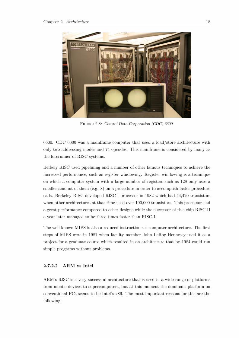
Figure 2.8: Control Data Corporation (CDC) 6600.
6600. CDC 6600 was a mainframe computer that used a load/store architecture with
only two addressing modes and 74 opcodes. This mainframe is considered by many as
the forerunner of RISC systems.
Berkely RISC used pipelining and a number of other famous techniques to achieve the
increased performance, such as register windowing. Register windowing is a technique
on which a computer system with a large number of registers such as 128 only uses a
smaller amount of them (e.g. 8) on a procedure in order to accomplish faster procedure
calls. Berkeley RISC developed RISC-I processor in 1982 which had 44,420 transistors
when other architectures at that time used over 100,000 transistors. This processor had
a great performance compared to other designs while the successor of this chip RISC-II
a year later managed to be three times faster than RISC-I.
The well known MIPS is also a reduced instruction set computer architecture. The first
steps of MIPS were in 1981 when faculty member John LeRoy Hennessy used it as a
project for a graduate course which resulted in an architecture that by 1984 could run
simple programs without problems.
2.7.2.2 ARM vs Intel
ARM’s RISC is a very successful architecture that is used in a wide range of platforms
from mobile devices to supercomputers, but at this moment the dominant platform on
conventional PCs seems to be Intel’s x86. The most important reasons for this are the
following:

Chapter 2. Architecture 19
• From the very beginning of PC industry PC applications were written for, or
compiled into x86 machines, while RISC does not have a similar installed base. As
a result users where forced to stick with this architecture since in order for this to
change a substantial amount of switching costs and discomfort would be required,
not to mention the compatibility issues that would arise.
• In fact RISC architecture was able to scale up in performance quite quickly and
cheaply, but Intel had vast amounts of money to invest in processor development.
As a result the x86 architecture started developing in a much faster pace compared
to the RISC architecture.
Since Intel’s x86 is the dominant platform on PCs a reasonable argument would be why
this does not apply to mobile devices. The main reason is that ARMs limited power
consuption is ideal for the portable devices, on the other hand x86 platform requires a
heavy power supply to power up the system. Of course x86 is usually more powerful than
ARM but usually this is not an issue on mobile devices since the majority of the OSs
used and the applications that run upon them are extremely lightweight. In addition,
x86 is a very backwards compatible system which is expected from desktops, but the
same does not necessarily apply to mobile phones and other mobile devices. Usually
mobile devices roll out with a particular operating system pre-installed and the user
rarely decides to change it.
Furthermore, ARM systems have an edge because as an open-licensed core, it has an
entire ecosystem of vendors that provide solutions on specific areas, thus it has a great
interface that allows it to connect easily with other devices. However, x86 chips are
produced solely by Intel. As a result the device manufacturers are forced to use the
components that Intel decides to bundle on their chips. Finally, this architecture
supports java programming which is an important factor for its extended use. In
addition, it should be noted that ARM processors are much smaller, making them ideal
for mobile devices.
2.7.3 Mobile Development
Mobile application development is the process of developing a program which runs on
low-power handheld device such as mobile phones, tablets and so on. These applications
can come pre-installed by the manufacturer of the device or can be downloaded and
installed from users afterwards. In addition they can be ordinary web applications that
run within the browser and may have been optimized for mobile use.

Chapter 2. Architecture 20
Applications were originally offered for general productivity and information retrieval
by their users. In the beginning, apps were used to view mails, weather conditions,
calendars and more, but later the public demand combined with the availability of the
advanced developer tools concluded in a broader range of categories such as mobile
games, mobile ticketing, social networking, e-banking, geolocation services and so on.
In addition web developers took into account the large rise in mobile device usage and
started building web applications optimized for small screens. Thus, there were no
restrictions concerning what operating system is used since the only program that is
needed for a web application is a web browser, which usually comes pre-installed on
every device. One more advantage of mobile optimized web applications is that they
do not require an installation and as a result no storage space is needed, although it
is usually required to download a certain amount of data in order to run properly the
cache can be cleared after the application has been used, freeing all used space.
Of course there are some disadvantages when using web applications instead of native
ones. Firstly, web browsers require to navigate into a specific web address. As a result
internet access is required at all times. This is an important disadvantage since there is
not always a WiFi available and 3G/4G data plans remain expensive in many countries
not to mention that 3G/4G signal is very limited in some locations. On the other
hand native applications can run entirely locally without requiring internet access. In
addition, as mentioned, web applications require navigation into a specific address which
means that typing is almost always required. This is usually not an issue when using
a PC but typing in a mobile device with a small touchscreen can be very inconvenient,
typing errors are easy to occur ruining the user experience of the application and causing
discomfort. On the other hand native applications either run entirely locally, so they
do not require any typing to connect, and even if they require some kind of online
transaction with a remote server they usually connect instantly in a predefined address
when opened by the user. Finally, native applications may use some extra space on
the memory of the device but they usually need a lot less internet usage in order to do
the same tasks that a web app does. This is caused due to the fact that usually when
using a web application the whole user interface has to be downloaded in order to be
rendered by the browser. On the other hand a native application, which requires internet
access, only needs the data from the server side since it is responsible for rendering them
correctly.
As we mentioned earlier, the developer usually uses an IDE in order to be able to
implement the application he wants easily and without concerns that have to do with
make-files, inclusion of the right libraries and so on. In addition, he needs the appropriate

Chapter 2. Architecture 21
SDK for the platform on which the application will run. In order to be able to test the
application, the developer needs to either use a testing device or an emulator.
Emulators are an inexpensive way for the developer to test his application on the
computer he uses to develop it. Usually these emulators are provided by the SDK
without any additional fee. When the programmer decides to use an emulator usually
a window appears that has the appearance of a phone with a fully functional operating
system. This means that even if the user cannot make calls he can navigate into the
applications, folders and settings of the virtual phone and test his application.
Another way of testing an application, is by using a physical device. Of course, this
is not always possible as the developer might not own a testing device. Additionally
many platforms, such as Apple’s iOS, require an extra fee in order to run the created
application into a physical device. Nevertheless, it is advised to test the application into
a device before publishing it, in order to make sure that no bugs appear on it.
2.7.4 Android Development
Android uses Activities to show the UI of the applications. It is a single focused screen
the user can interact with. The programmer has in his disposal some standard functions
to manipulate the behavior of this screen during the various stages of the application.
These various stages of an application, are known as the Activity’s Lifecycle. Activities
are managed using an activity stack. When a new activity is started, it is placed on
the top of the stack, which contains other running activities. An activity remains below
another newly added Activity until the later one exits. At that time the older Activity
returns to the foreground.
2.7.4.1 Activity Lifecycle
Activities can rotate between four stages:
• Active or Running is an activity that is placed at the top of the Activity Stack.
The UI of this Activity is shown to the user and he/she can interact with it.
• Paused is an Activity when it has lost focus because another non-full sized or
transparent Activity is on top of it at the Activity Stack. A paused Activity is
considered to be alive keeping the state and the variables it had before, but if the
OS decides that there are extremely limited resources it will be terminated.

Chapter 2. Architecture 22
Figure 2.9: Activity States with Callback Methods.
• Stopped is an Activity when it is completely covered by another one. In this
state the Activity is not visible to the user and is considered to be stopped until
the OS decided to kill it due to limited resources.
• When an Activity is either stopped or paused and the resources are coming to an
end, the OS ”asks” the Activity to finish. If this does not happen it is killed by the
OS. When the user resumes this terminated Activity must be completely restarted
and restored to the previous state.

Chapter 2. Architecture 23
Callback methods, if implemented enable a programmer to perform operations during
the transition of the Activity from one state to the other.
The three loops that a programmer should be aware of while developing an Android
application are the following:
• The entire lifetime of an Activity happens between the first call to onCreate()
through the final call to onDestroy(). This means that an Activity will do a
setup of the state and the resources that will be required on onCreate() and will
release the resources on onDestroy(). For example, in the application developed
for this Thesis, at one point an Activity creates two background services that are
responsible for sequential calls to the Web Service. When this Activity reaches
its final stage these two background services must be stopped and another request
has to be sent to the Web Service to terminate the operation that is executed. All
these operations occur on the onDestroy() function.
• The visible lifetime of an activity happens between a call to onStart() until a
corresponding call to onStop(). During this time the user can see changes to the
Activity even if it is not on the foreground. It is a good practice to create an
operation that is influenced by such changes at the onStart() function and destroy
it on the onStop() function as no changes will occur after this function is called.
• The foreground lifetime of an activity happens between a call to onResume()
until a corresponding call to onPause(). During this period the Activity is in front
of other Activities and interacting with the user. A great example that shows the
meaning of this cycle is the following: If an Activity is changing constantly, for
example a graph is being drawn in real-time, and the device goes to sleep, the
interface will keep changing even if the user cannot see any change. This results in
a higher power consumption and an overall bad implementation. The drawing of
the graph can be paused on the onPause() function and resumed when the activity
regains focus if a s without losing any values.
At this point it has to be mentioned that an application does not necessarily implement
all those methods. Many of them can be omitted as long as the application runs correctly
without crashing, consuming valuable resources when they should be free and so forth.
2.7.4.2 Screen Sizes in Android
Android is intended to run on devices with various screen sizes and the same applies to
the Android applications. This fact can cause problems on some Activities and a special

Chapter 2. Architecture 24
care should be provided from the programmer. This special care may include alternative
resources that optimize the user experience on every available screen size.
Two general properties categorize the screen of every device: size and density. The size
of a screen can be small, normal, large or extra large and the density can be low (ldpi),
medium (mdpi), high (hdpi) or extra high (xhdpi).
Special directories are provided for the necessary resources, which have to be properly
scaled to the various density buckets. The appropriate scale for each density bucket is:
• xhdpi: 2.0
• hdpi: 1.5
• mdpi: 1.0 (baseline)
• ldpi: 0.75
This means that if an image is required in 20x20 dimensions for an xhdpi screen the same
image must be created in 15x15 for an hdpi screen, in 10x10 for mdpi and in 7.5x7.5 for
ldpi screens.
2.7.4.3 Different Platform Versions
Android is constantly under development. This results in a broad range of changes
on the various methods and functionalities from one version to the other. While from
one perspective this is a positive feature, as it means that bugs and security issues are
resolved, the changes made from one Android version to the other, may require specific
code for a functionality to run properly, that depends on the version of Android.
Android and Google offer to the programmer tools that show real-time stats of the
devices that interact with Google Play, which is the store a user can visit to download
new applications. These stats can be useful to a developer as they give information
concerning which Android versions should be supported the most. If an Android version
is installed on the vast majority of the device that interact with this store, then it
certainly is advised for this version to be supported.
During the development of the Android application of this thesis this problem arose
several times. Apart from the fact that some functions where no longer supported on
later versions of Android, or they are deprecated, which meant that this specific part
had to be implemented differently. Some functions, changed drastically causing crashes
when run on versions different from the one used for testing.

Chapter 2. Architecture 25
Figure 2.10: SOAP Web Services.
Android allows the programmer to specifically set the supported versions of Android
but this certainly does not solve the problem. As a result many blocks of code had
to be version specific. Thankfully, Android provides functionality that can make this
process easier, as a simple function can return information about the system of the
device, but again this version specific code at times is so extended that has resulted in
many problems on the Android community.
At the time, these lines were written a bundle had just rolled out from Google that
included libraries used in previous versions of Android. The purpose of this bundle is to
allow the programmers make applications backwards compatible easier, but again this
may end up creating more problems.
2.8 Web Services
Web Services enable the communication between two electronic devices over the World
Wide Web. According to W3C a Web Service is ”a software system designed to support
interoperable machine-to-machine interaction over a network”. To enable this over-the-
network interaction, many protocols can be used including but not limited to HTTP.
There are two known types of Web Services, SOAP based and REST. Both of which
will be analyzed here.
2.8.1 SOAP Based Web Services
Typically, they provide an interface described in an XML-like document called Web
Services Description Language (WSDL). This document in particular is used to describe

Chapter 2. Architecture 26
the functionality offered by the service and the rules the clients need in order to make
valid requests to the Web Service and receive responses in a predictable format.
More specifically, WSDL describes services as a collection of network endpoints, or
ports. A port is defined by associating a network address with a reusable binding, and
a collection of ports defines a service. Messages are abstract descriptions of the data
being exchanged, and port types are abstract collections of supported operations.
WSDL is usually combined with SOAP and an XML Schema to provide Web Services
over the internet. Clients are connected to a Web Service by accessing the WSDL file.
That way the client can determine what operations are offered by the service provider.
SOAP is used in order to call one of these operations using XML files or other binding
mechanisms.
There are two types of SOAP requests. The first one is Remote Procedure Call (RPC)
style requests, which usually is synchronous. By synchronous we mean that the client
transmits a request and waits for the response from the server. The second type is the
document request. In this type of SOAP request, a complete XML file is transmitted
from the client to the server and a response, which once again is an XML file, is returned.
2.8.1.1 RPC
SOAP-RPC is an implementation of a Remote Procedure Call. In this case, there is an
inter-process communication that allows a program to call a subroutine to execute in
a remote computer as if it was a local function. Additionally, the programmer is not
obligated to write code for the various details of this interaction. He just follows some
specifications and writes the same code he would write if this function was executing
locally.
This communication is initiated by the client. The client sends a request to a remote
server, including the parameters that would be sent if the function was executed locally.
After the server processes the data included in the request message it sends a response.
During this time, the client is blocked, it cannot go on executing the rest of the lines
of code as it has to wait for the service to respond. This of course, applies to the cases
where no asynchronous mechanisms are used.
Some worth-mentioning problems that may occur during this interaction, which cannot
occur during a local function call are the various network problems. The challenging
part usually is the fact that during these network failures the clients cannot know if the
remote procedure was actually invoked or not. In this case a simple recall would solve

Chapter 2. Architecture 27
Figure 2.11: SOAP Structure.
the problem but this does not apply to the occasions where the procedures have different
functionality depending on the number of times they are called.
2.8.1.2 Document Transmission
In this type of message exchanging a complete XML document (or a document created as
a part of another marshaling-unmarshaling mechanism e.g JSON in a SOAPjr Service) is
transmitted as the body of the SOAP message instead of simple parameters. A schema
common to both the sender and the receiver is used to encode and decode the data.
When responding to the request, the server side does not send just a single returning
value, instead, a complete document is sent that contains all the information that a
normal invoice would have, the difference is that in this case the document is marked-up
and machine readable.
This style of messaging has some advantages over the RPC style messaging. For starters,
RPC callings are relatively static. If the service provider decides to change the RPC
interface, even slightly, he will break the contract between the server and the client. As
a result an application that has the role of a client in an RPC service will malfunction.
On the other hand, the rules on a document transmission are more flexible and less rigid.
On a document exchange that uses XML, changes can be made to the XML schema
used to bind the data, without resulting in a faulty communication between the server
and the client. The changed XML document will be transmitted and the new XML
schema will be used to unbind the data, without causing problems to the transmission
of the data. Furthermore, since in this case the message is a self contained document,
it is more suitable for an asynchronous communication.
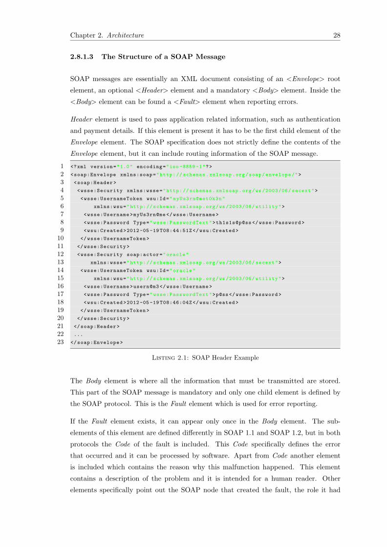
Chapter 2. Architecture 28
2.8.1.3 The Structure of a SOAP Message
SOAP messages are essentially an XML document consisting of an <Envelope> root
element, an optional <Header> element and a mandatory <Body> element. Inside the
<Body> element can be found a <Fault> element when reporting errors.
Header element is used to pass application related information, such as authentication
and payment details. If this element is present it has to be the first child element of the
Envelope element. The SOAP specification does not strictly define the contents of the
Envelope element, but it can include routing information of the SOAP message.
1 <?xml version="1.0" encoding="iso -8859 -1"?>
2 <soap:Envelope xmlns:soap="http: // schemas.xmlsoap.org/soap/envelope/">
3 <soap:Header >
4 <wsse:Security xmlns:wsse="http: // schemas.xmlsoap.org/ws /2003/06/ secext">
5 <wsse:UsernameToken wsu:Id="myUs3rn@met0k3n"
6 xmlns:wsu="http: // schemas.xmlsoap.org/ws /2003/06/ utility">
7 <wsse:Username >myUs3rn@me </wsse:Username >
8 <wsse:Password Type="wsse:PasswordText">th1s1s@p@ss </wsse:Password >
9 <wsu:Created >2012 -05 -19 T08:44:51Z </wsu:Created >
10 </wsse:UsernameToken >
11 </wsse:Security >
12 <wsse:Security soap:actor="oracle"
13 xmlns:wsse="http: // schemas.xmlsoap.org/ws /2003/06/ secext">
14 <wsse:UsernameToken wsu:Id="oracle"
15 xmlns:wsu="http: // schemas.xmlsoap.org/ws /2003/06/ utility">
16 <wsse:Username >usern@m3 </wsse:Username >
17 <wsse:Password Type="wsse:PasswordText">p@ss</wsse:Password >
18 <wsu:Created >2012 -05 -19 T08:46:04Z </wsu:Created >
19 </wsse:UsernameToken >
20 </wsse:Security >
21 </soap:Header >
22 ...
23 </soap:Envelope >
Listing 2.1: SOAP Header Example
The Body element is where all the information that must be transmitted are stored.
This part of the SOAP message is mandatory and only one child element is defined by
the SOAP protocol. This is the Fault element which is used for error reporting.
If the Fault element exists, it can appear only once in the Body element. The sub-
elements of this element are defined differently in SOAP 1.1 and SOAP 1.2, but in both
protocols the Code of the fault is included. This Code specifically defines the error
that occurred and it can be processed by software. Apart from Code another element
is included which contains the reason why this malfunction happened. This element
contains a description of the problem and it is intended for a human reader. Other
elements specifically point out the SOAP node that created the fault, the role it had

Chapter 2. Architecture 29
and other details concerning the problem. The programmer can use these error codes
while developing the client application and the web service or he can use other structures,
which he has to define by himself with an XML schema, that describe the problem
1 <soap:Envelope xmlns:soap="http: //www.w3.org /2003/05/ soap -envelope"
2 xmlns:xml=http://www.w3.org/XML /1998/ namespace
3 xmlns:wsa="http:// schemas.xmlsoap.org/ws /2004/08/ addressing"
4 xmlns:dsc="http:// schemas.microsoft.com/windows /2008/12/ wdp/
5 distributedscan/configuration">
6 <soap:Header >
7 <wsa:Action >http:// schemas.xmlsoap.org/ws /2004/08/ addressing/fault </wsa:Action >
8 <!-- Headers excluded for brevity -->
9 </soap:Header >
10 <soap:Body >
11 <soap:Fault >
12 <soap:Code >
13 <soap:Value >soap:Receiver </soap:Value >
14 <soap:Subcode >
15 <soap:Value >dsc:ClientErrorJobTokenNotFound </soap:Value >
16 </soap:Subcode >
17 </soap:Code >
18 <soap:Reason >
19 <soap:Text xml:lang="en">A PostScan job identified by the
20 specified dsc:JobToken argument could not be found.</soap:Text >
21 </soap:Reason >
22 </soap:Fault >
23 </soap:Body >
24 </soap:Envelope >
Listing 2.2: SOAP Body Example that contains Fault element
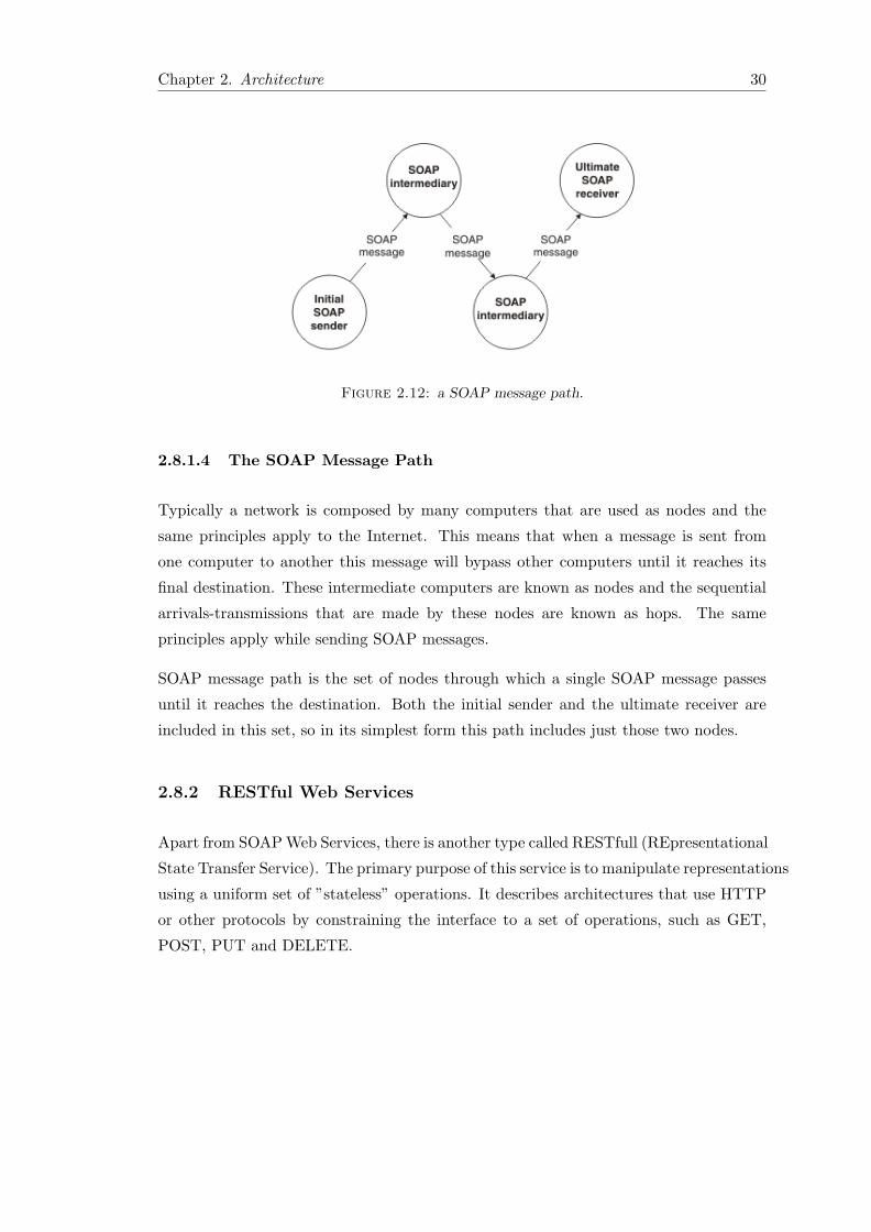
Chapter 2. Architecture 30
Figure 2.12: a SOAP message path.
2.8.1.4 The SOAP Message Path
Typically a network is composed by many computers that are used as nodes and the
same principles apply to the Internet. This means that when a message is sent from
one computer to another this message will bypass other computers until it reaches its
final destination. These intermediate computers are known as nodes and the sequential
arrivals-transmissions that are made by these nodes are known as hops. The same
principles apply while sending SOAP messages.
SOAP message path is the set of nodes through which a single SOAP message passes
until it reaches the destination. Both the initial sender and the ultimate receiver are
included in this set, so in its simplest form this path includes just those two nodes.
2.8.2 RESTful Web Services
Apart from SOAPWeb Services, there is another type called RESTfull (REpresentational
State Transfer Service). The primary purpose of this service is to manipulate representations
using a uniform set of ”stateless” operations. It describes architectures that use HTTP
or other protocols by constraining the interface to a set of operations, such as GET,
POST, PUT and DELETE.

Chapter 2. Architecture 31
Figure 2.13: RESTful Web Services.
State is a technical term used to describe a set of stored information, at a given point in
time to which a program has access to. As the Web Service is called from different clients,
it is a better approach to consider every request as a new one. This results in a less
complex and a ”cleaner” service with a more predictable behavior. An implementation
which has the above-mentioned characteristics is considered stateless.
As all service do, REST services provide access to resources. A client uses a way to
identify the resources that are needed, such as using URIs when interacting with a
web based REST service. Later, a representation of the requested resources is returned
to the client. Usually these resources are returned in a form that allows them to be
recognized and manipulated correctly by the client. Standard ways to represent the
data in order to be transmitted are HTML, XML or JSON bindings. Apart from the
format of the returning information, the identifier of the resource and the action required,
the client does not need to know any network-specific information. For example, the
calling application does not need to know any details considering whether or not there
are caches, proxies or other elements between the client and the service.
In a REST service the client is in command. When a client has in its disposal a
representation of a resource, it also has all the needed information that would allow
it to make a modification or even delete the entire resource from the server, provided
that it has the rights to do so.
Hypermedia as the Engine of Application State (HATEOAS) is one of the constraints
of the REST application architecture. The main principle is that the client can interact
with a server side application using hypermedia generated dynamically by the service.
As a result, a REST client can interact with a server without prior knowledge of the

Chapter 2. Architecture 32
Figure 2.14: REST vs SOAP.
interface used by the service. Apart from some fixed endpoints that usually are known
in advance, a client uses the information retrieved by the service in order to proceed
using and manipulating the resources provided. This opposes to the way SOAP services
operate, as a specific contract in a form of a fixed interface is used to provide information
concerning all the available functionality of the service.
2.8.3 REST vs SOAP
Although, Web API is moving away from SOAP based services and more into RESTfull,
in this thesis implementation, we chose to build a SOAP Web Service. There are many
advantages and disadvantages of both these types of services.
Firstly, REST services are indeed very lightweight. They are not as complex as SOAP
services are, but despite the fact that they are very light and easy to implement they
are not as secure as SOAP services are. SOAP services have been a standard for many
years, they have been used ceaselessly by many service providers and there are many
APIs that can be used to build great services, especially in JAVA.
A certain drawback that SOAP services have is that they require more bandwidth than
REST services do, since XML is primarily used for the interconnection between the
client and the server, more data are transmitted. The messages transmitted in a SOAP

Chapter 2. Architecture 33
service include information that is seemingly useless and can be avoided. This is utilized
in REST services but since in our case the transferred data are not that big and since
we had the chance to exclude some of the unused data from the XML messages, these
disadvantages were limited to the minimum. Apart from that, the security factor of
SOAP services gave a certain advantage.
Furthermore, as SOAP services have been used for more years than REST services,
there are many tools available to choose from and many bugs and problems have been
eliminated over the years. Additionally, since the greatest part of the processing of data,
during this interaction between the server and the client, is performed on the server side,
as opposed to REST services, (where more workload is brought upon the client side) the
SOAP approach was preferred. The reason why SOAP was preferred is that in our case
the client is a mobile application, that runs on a device with limited capabilities, while
the server is a much more powerful machine.
Additionally, as we mentioned there are many APIs and tools available for building a
SOAP web service, this results in more features that can be utilized. For example as
we mentioned before, a standard way of using a web service is: a client makes a request
to a specific address and after a while the server side responds to that request with the
available data. This surely seems to be more than simple but what happens when the
server side needs to send data to the client without receiving a request? If for example
an event occurs on the server side, that would trigger a process during which information
should be returned to the client without any requests from it, there could be a problem.
In a SOAP service this is no issue. Asynchronous communication can be implemented
by a couple of methods, and can solve this problem.
2.8.4 (Un)Marshalling
Usually the intermediate level, has to operate on data related to an object. This object
has to be transmitted to the client but in order for this to happen it must be encoded
in some way that will make the communication between the server and the client easier.
This is done by marshalling. Marshalling is the conversion of an object into a data
structure such as an XML, JSON or other formats in order to transmit it or to store
it. Unmarshalling is the reverse procedure but it is common to refer to both types of
conversion as marshalling.
Marshalling is also considered synonymous with the term serialization. This is not
entirely true since marshalling records the state and the codebase in a way that when
this object is unmarshalled a complete copy of the original object is obtained including,
in most cases, the class definition of an object. On the other hand serialization is just
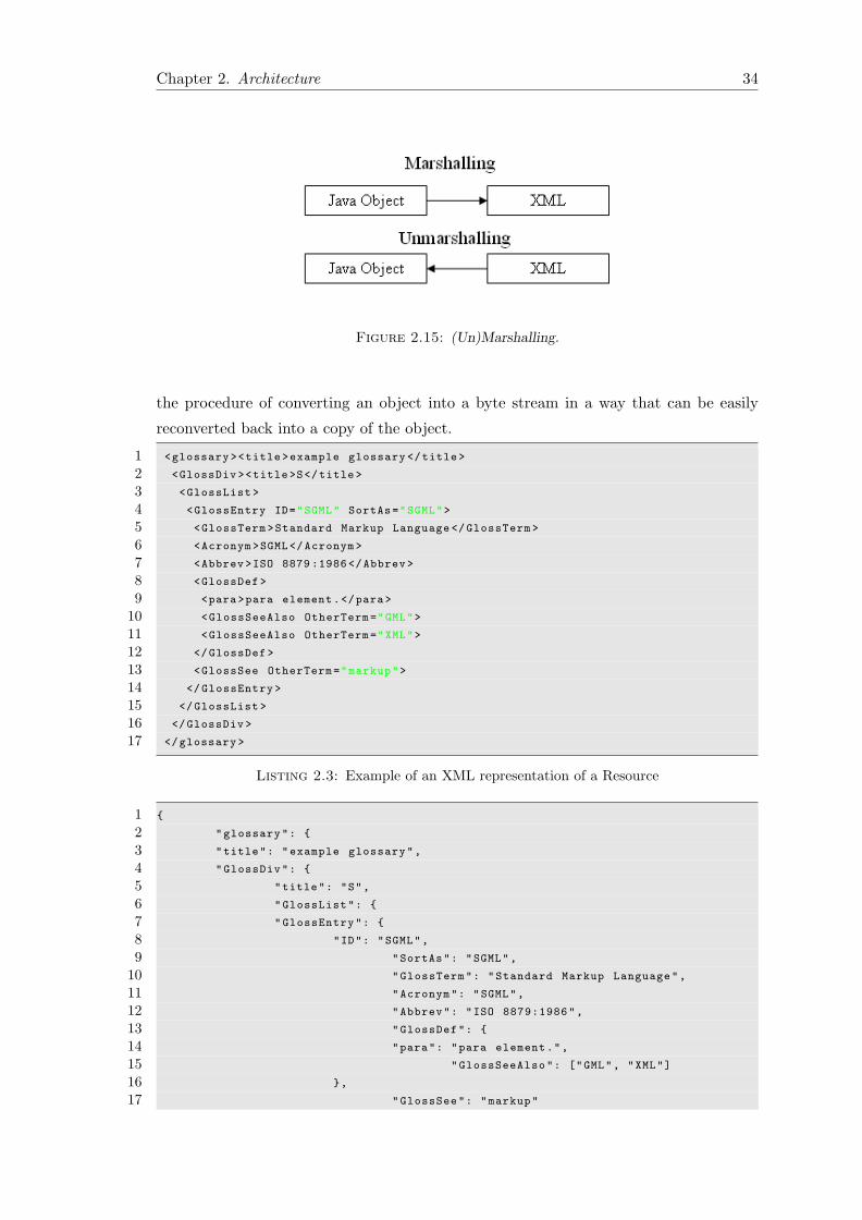
Chapter 2. Architecture 34
Figure 2.15: (Un)Marshalling.
the procedure of converting an object into a byte stream in a way that can be easily
reconverted back into a copy of the object.
1 <glossary ><title>example glossary </title >
2 <GlossDiv ><title>S</title >
3 <GlossList >
4 <GlossEntry ID="SGML" SortAs="SGML">
5 <GlossTerm >Standard Markup Language </GlossTerm >
6 <Acronym >SGML</Acronym >
7 <Abbrev >ISO 8879 :1986</Abbrev >
8 <GlossDef >
9 <para>para element.</para>
10 <GlossSeeAlso OtherTerm="GML">
11 <GlossSeeAlso OtherTerm="XML">
12 </GlossDef >
13 <GlossSee OtherTerm="markup">
14 </GlossEntry >
15 </GlossList >
16 </GlossDiv >
17 </glossary >
Listing 2.3: Example of an XML representation of a Resource
1 {
2 "glossary": {
3 "title": "example glossary",
4 "GlossDiv": {
5 "title": "S",
6 "GlossList": {
7 "GlossEntry": {
8 "ID": "SGML",
9 "SortAs": "SGML",
10 "GlossTerm": "Standard Markup Language",
11 "Acronym": "SGML",
12 "Abbrev": "ISO 8879:1986",
13 "GlossDef": {
14 "para": "para element.",
15 "GlossSeeAlso": ["GML", "XML"]
16 },
17 "GlossSee": "markup"

Chapter 2. Architecture 35
18 }
19 }
20 }
21 }
22 }
Listing 2.4: Example of an JSON representation of the Same Resource
2.9 TinyOS Architecture
TinyOS is an open source, BSD licensed operating system specially designed for low-
power wireless devices. The main difference between this architecture and the one used
in traditional Operating Systems is that the requirements of the later system are too
demanding.
Specifically, in a traditional OS there are large memory and storage requirements in order
to support functionalities that seems rather useless for a sensor mote. Additionally, a
standard Operating System is undoubtedly too complex and power consuming for a
wireless device.
An ideally designed device for our purpose should have efficiency as a main attribute,
in order to run as a node on a sensor network. By efficiency, we mean that we want
an architecture with a small footprint, with a low system overhead and certainly with
a low power consumption, as those characteristics are crucial for every remote/mobile
device, because these devices are intended to run solely on batteries and it is intended
to do this for a long period of time. Apart from these elements, all the rest that are
usually found on the majority of the Operating Systems intended for use on a PC, such
as a subsystem responsible for the UI, are just a burden in our case.
TinyOS is ideal for running on low power motes, as it is bundled with all the required
components, but without the extra weight of the unnecessary ones. TinyOS does not
include a kernel. This means that there is a direct hardware manipulation that limits
the resources needed for the completion of a task and at the same time, this immediacy,
although it seems to lead to a somewhat low level programming, at the end of the day,
it serves well its purpose.
The unnecessary system overhead is stripped down by a number of other ways too.
Firstly, there is no process management as there is only one process needed that runs
on the fly. Furthermore, there is no virtual memory as it is simply not needed. There is
just a single linear physical address space. What is more, there is no dynamic memory
allocation mechanism, which means that the memory is assigned at compile time. This
Chapter 2. Architecture 36
system although very efficient, it can be dysfunctional if the image of the program that
runs on this systems ends up being too big. So the programmer should make sure
that the application will remain small. Additionally, other problems may occur due to
memory issues that may result in faulty behavior of the program while running.
When applying a closer look on TinyOS, one can notice that there is a certain separation
of construction and composition. Components contain ”slices” of code responsible for
a specific functionality. Apart from the applications, the libraries are also bundled in
components. Two or more components are wired together using an interface.
The programming language used for the synthesis of those components is nesC. NesC
is a language that resembles C but some additional features, are added to fully support
the functionality needed in TinyOS.
2.9.1 Interfaces
In the TinyOS framework a component can either provide or use an interface. Interfaces
describe a logical related set of commands and events. When a component provides an
interface, it provides a functionality to the component that uses it. The used interfaces
represent the functionality the components need in order to be able to perform the task
they are intended to.
In TinyOS interfaces are bidirectional. This means, that interfaces provide a set of
commands that have to be implemented by the interface’s provider and a set of events
that have to be implemented by the component that uses a particular interface, otherwise
an error will occur. Additionally, a component can use or provide multiple interfaces
and multiple instances of the same interface. The set of interfaces a component uses
and provides is called that component’s signature.
2.9.2 Modules & Configurations
Modules and Configurations are two types of the components found in TinyOS. Modules
provide the source code, the implementation of an interface, while configurations are used
to assemble components together. Typically the process of connecting interfaces used
by a set of components with interfaces provided by others, is called wiring.
2.9.3 Singletons & Generic Components
Two other types of components in TinyOS are singletons and generic components.
Singletons are unique, they exist in a global namespace and as a result they can only

Chapter 2. Architecture 37
exist once, while generic components can have multiple instances. Two configurations
that use the same singleton component are essentially accessing the same variables.
2.9.4 Events & Tasks
Another interesting set of features in TinyOS is the asynchronous events and tasks.
Tasks cannot preempt each other, events can preempt tasks since they have a higher
priority and events can preempt each other once enabled. This is critical in many ways.
If for example two messages arrive at the same time to a mote, the appropriate event
will get fired twice overriding the variables formerly containing useful information. This
will have as a result the loss of one of two messages. If on the other hand, the data
included on the messages are instantly copied to other memory locations, as soon as the
events are fired and tasks are posted to process these data,they will not be overridden
and no data loss will occur. TinyOS scheduler runs tasks one by one in the order they
are posted until their completion.

Chapter 3
Requirements Analysis, User
Interface Prototyping and
Evaluation
3.1 Introduction
Before the implementation of every application begins, a set of requirements has to be
defined. Designers should be able to visualize the product along with the functionality it
will provide. It is important to clarify what exactly the product is about. ”What is the
problem this application is about to solve?”, and ”how does this application solve the
problem in a better way than other products?”, are questions that should be answered
before continuing to the implementation.
After having answered these questions, we can go to the next step, which is the actual
design of the interface. Usually the developers have a specific model of the final product
in mind, which they know that can be implemented (since they have the technical skills)
and they believe that it will be adopted by the end-users. Unfortunately, this usually is
far from the truth. Programmers are not always the most representative users. If the
final product has as a target group, tech-savvy people, then programmers may be the
best for this job, but if this is not the case their final design will probably not be that
good. It is therefore significant to use real users to evaluate the interface.
By creating paper prototypes, the developing team can easily brainstorm on the design
of the application and later, use these prototypes to evaluate the interface. This method
is easy, fast and efficient. The prototypes are created easily, in just a few minutes or
hours at most, and after they have been evaluated by the users, it is also easy and fast
38

Chapter 3. Requirements Analysis, User Interface Prototyping and Evaluation 39
to make adjustments on them or to throw them away and create new ones from scratch
to solve potential problems. It is noteworthy that the alternative would be to implement
the entire application, use real users to evaluate it and then make adjustments. That
would require too much time if major changes were required, so it is preferable to spot
design errors from an early stage and solve them before they reach the next stages.
In this chapter, we describe the entire process of requirement analysis, paper prototyping
and evaluation using real users. Additionally, more information about other techniques
such as personas, storyboardings and more will follow.
3.2 Personas
Personas are fictional characters created to imitate the users of a product. By analyzing
the special characteristics and attributes of a persona, the designer is able to understand
the requirements of the product and the criteria that must be met in order to be
successful.
Particularly, instead of having an abstract idea about potential users the designer puts
a face on a representative sample user. Instead of dealing with abstract imaginary users,
he has to deal with a specific person, that has a particular educational background,
certain needs and concerns and a specific ability to adapt to new technologies.
This process in overall leads to a better understanding of the users. Usually, developers
put themselves in the user’s position in order to be able to figure out the interface of the
application they are building. However, the developers may have nothing in common
with the target users and as a result it is rather doubtful that this product will eventually
satisfy the needs of the target group. By using personas, on the other hand the entire
developing team tries to figure out the unique characteristics of the end user and create
a design that suits him and covers his needs.
Bellow, there is a extensive analysis of the personas used for this specific application.

Chapter 3. Requirements Analysis, User Interface Prototyping and Evaluation 40
3.2.1 Anne, 41, Professor
Figure 3.1: ProfessorAnne
Name: Anne
Age: 41
Research Interests:
• Advanced compact MOSFET models
• Analog—RF integrated circuit design
• RF characterization & modeling of nanoscale
electronic devices
Professional Service: Regular reviewer for IEEE
Trans. on Electron Devices,IEEE Trans. on CAD of Int.
Circuits and Systems.
Teaching:
• ACE 506: Design of CMOS Analog Integrated Circuits
• ACE 604: Special Themes of Analog IC Design
Anne is a well-known researcher of the field of electronics. She received her bachelor’s
degree from the National Taiwan University and her Ph.D. in electrical engineering
from U.C. Davis. She has a long list of publications on her field of interest and she is
currently working into a revolutionary method of constructing a transistor that will lead
to a radical increase on the processing power of CPUs.
Anne uses PCs and smartphones into her everyday life. She is certainly able to use
applications that do not have the most user-friendly interface, but she definitely prefers
to use web and mobile applications with a sleek, easy to use interfaces that follow the
design patterns used by the vast majority of today’s applications.
She might be interested in this product as it will help her in the research she currently
does. Electrical circuits and transistors are easily affected by the environmental conditions.
Her lab does have all the necessary equipment to measure the temperature and humidity
in the room were it is placed, but the problem is that she is not always in her lab. She has
many responsibilities, such as preparing for lectures, office hours, attending workshops
and seminars, that force her to spend time outside of the lab.
On the other hand she is concerned that her T.A. students that have access to the lab
might change the temperature of the room, and cause critical problems to her work.
This application allows her to endlessly monitor the conditions of the lab at any time.

Chapter 3. Requirements Analysis, User Interface Prototyping and Evaluation 41
She could be traveling to another country in order to attend a conference or she could
be at her house relaxing after a long day, and she could still be positive that her project
remained intact. Additionally, the outlier detection algorithm helps her notice any
abnormalities that may occur in her lab, again from any location.
3.2.2 John, 63, Businessman
Figure 3.2: Mr. John
Name: John
Age: 63
Education:
• University of Phoenix
• University of Wisconsin-Madison - School of
Business
• Shasta College
Currently: President and Founder at Johnson - Murray
and Sons, Inc. & Real Estate Consultant & VP of Luxury
Home
John is a businessman with many years of experience in the industrial world. He is
constantly talking with his associates from around the globe on the phone and is always
on the go. The airports are his second home, as he travels a lot in order to take care of
all his business matters.
John, does not like computers. Since, he is used in traveling a lot, he feels constraint
while using them, even laptops seem inconvenient to him as they are rather heavy to
carry around at all times. Additionally, their battery life is not that good and he has to
recharge them constantly. On the other hand, John has always with him his smartphone
because it allows him to check his mail and communicate with his associates free of
charge.
He might be interested in this product because he currently is the president of a well-
known firm, that recently bought a building to use as a factory. In this factory, expensive
but sensitive to high temperatures equipment will be used and he is worried that if he
does not take special care of the indoor temperature and humidity the equipment will
be ruined. Since this is a new factory in a foreign country he does not know if there is
anyone responsible enough to take care of this problem for him, so he has to do it by
himself.

Chapter 3. Requirements Analysis, User Interface Prototyping and Evaluation 42
This product will allow him to keep taking care all his business matters without worrying
about the equipment of this factory. If he is worried, he can just check the temperature
on each and every one of this factory’s rooms and make sure that everything is fine. If
on the other hand, a problem occurs the outlier detection algorithm will help him find
out that there is a problem and either get to the factory by himself to solve the problem
or send one of his assistants.
3.2.3 Katia, 23, Undergraduate Student
Figure 3.3: Ms Katia
Name: Katia
Age: 23
Education:
• Undergraduate student at the Conservation of
Antiquities and Works of Art Department at the
Technological Educational Institute of Athens
• 23th High-school of Athens
Currently: Working as an intern at the Academy of Athens
and at the same time working on her Thesis assignment.
Katia is a young female student that currently works as an intern at the Academy
of Athens. As every young energetic 23-year-old she is an excellent user of technology
related products. She always carries around her smartphone and she is always connected
with her friends over social networks.
Apart from that, Katia although not a poweruser, she considers her smartphone to be a
very powerful tool, and she uses it as such. When she is lost or just trying to get from
point A to point B using public transportation she uses Google Maps, she checks her
mails on the go, reads news portals and uses other programs to make her life easier.
She might be interested in this product because at the Academy of Athens where she
currently works, the administrator has set up a number of sensors. She along with the
administrator can be held responsible for the monitoring of the conditions of the room
where delicate ancient artwork is positioned. These artifacts under the right conditions
can be preserved for a very long time, and since the room in which they are placed is used
as an exhibition room, this system can ensure that the criteria for the ideal conditions
will be met.

Chapter 3. Requirements Analysis, User Interface Prototyping and Evaluation 43
3.3 Storyboarding
Storyboarding in Software Engineering is used to describe the specifications of a particular
software. During this phase, the user interface of project is decided, or to be more
precise, an early stage of that interface. These prototypes can take less than a day to
be completed for an entire system, as opposed to a finalized software system. They are
easy to share at large groups and they do not give the false impression that the system
is already developed. After all, the project is just at the beginning and this phase exists
just to make sure that the developing team is pointing to the right direction. The users
that are going to have access to the storyboards during the testing phase should feel
that it is something easy to create and throw away. That way it will be easier for them
to give a negative feedback, if necessary.
Storyboards are performed in many different ways. They sometimes are created electronically,
although they may end up taking too much time and ending up looking too detailed for
their purpose, or they could be little sketches on white boards or on papers. Usually,
they look like raw comics, a simple picture of an interface that includes the buttons and
figures that are going to be positioned there is more than enough. Of course, they could
even include drawings of people using the software on their everyday lives, it is up to
the developing team to use it in the way that suits them, it can even be used to boost
the morale and bonding of the team, but it is vital to be understandable by the users.
The following images illustrate how this project was initially conceived, and how the
requirements were set at first.

Chapter 3. Requirements Analysis, User Interface Prototyping and Evaluation 44
Figure 3.4: Storyboarding 1st Image.
Figure 3.5: Storyboarding 2nd Image.

Chapter 3. Requirements Analysis, User Interface Prototyping and Evaluation 45
Figure 3.6: Storyboarding 3rd Image.
Figure 3.7: Storyboarding 4th Image.

Chapter 3. Requirements Analysis, User Interface Prototyping and Evaluation 46
Figure 3.8: Storyboarding 5th Image.
Figure 3.9: Storyboarding 6th Image.

Chapter 3. Requirements Analysis, User Interface Prototyping and Evaluation 47
These illustrations show some simple screens of the application. As mentioned they are
the first step towards the final user interface of the program. Once this step is completed
it is easier to get in contact with end users and find out if the UI of the application is
understandable or if improvements should be made.
3.3.1 Receiving Feedback
After showing these images to potential users we were able to collect feedback that would
allow us to make the interface better. At first glance, the users noticed that the interface
seemed to be similar to other well-known applications such as Facebook, Google Plus
and others. This was intentional and it is undoubtedly a positive feedback. By using a
familiar interface the user spends less time familiarizing himself with it and more time
actually using it.
The users faced some problems considering the terminology used. For example when
the user chooses the option: ”Measurement Retrieval” a screen appears that contains
the term: ”TCT” this is because the program that operates on the sensor network
implements TiNa, a scheme used to minimize energy consumption. While it is critical
to make sure that no misconceptions exist from the user, this fix has a low priority as the
users will be informed about the various operations of the system, when it is delivered
to them. An easy fix, however, would be to include a button next to it. This button
when clicked on, it could show information or even examples of how this function could
be used.
On the other hand, some of the users expressed concerns about the fact that it may
be difficult for them to spot a more ”secret” link. Specifically, the storyboards show
that by taping on the top of the screen, where the user’s name and avatar picture is
displayed, they could have access to a screen that includes all the personal data given
by them when singing up. This has certainly a higher priority and it will be fixed on
the next stage.
Overall, this stage was successful, it appears that the interface will be familiar to the
users but some minor changes should be implemented to make it even better. These
changes will be viewed on the next stage, which is the paper prototyping.

Chapter 3. Requirements Analysis, User Interface Prototyping and Evaluation 48
3.4 Paper Prototyping
Paper prototyping is a widely used method in Human-Computer Interaction. It provides
the opportunity to create software that meets the user’s expectations. During this stage,
again, hand-sketched or computer made drawings of the interface are created, but these
prototypes are usually more detailed when compared to the ones created during the
storyboarding phase.
The main idea is the same; developers use this technique to test the interface they have in
mind, using real life users, without writing a single line of code. While paper prototypes
are usually more detailed, as it can be observed from the following images, it certainly
requires far less time to create, compared to the time that would be needed if the entire
user interface was implemented programmatically, and thus it is easier to make changes.
Usually, during this stage simple office supplies are used once again like pen and paper.
Since in our case we try to create the user interface of a mobile device, the paper
prototypes should look like mobile phones. Thankfully, it was not necessary to draw
multiple instances of the layout of a mobile phone, because a simple layout was found
online and was used instead. This helped us focus on the actual UI design without
wasting too much time creating a drawing of a mobile device.

Chapter 3. Requirements Analysis, User Interface Prototyping and Evaluation 49
Figure 3.10: Paper Prototyping 1st Image.
Figure 3.11: Paper Prototyping 2nd Image.

Chapter 3. Requirements Analysis, User Interface Prototyping and Evaluation 50
Figure 3.12: Paper Prototyping 3rd Image.
Figure 3.13: Paper Prototyping 4th Image.

Chapter 3. Requirements Analysis, User Interface Prototyping and Evaluation 51
Figure 3.14: Paper Prototyping 5th Image.
Figure 3.15: Paper Prototyping 6th Image.

Chapter 3. Requirements Analysis, User Interface Prototyping and Evaluation 52
3.5 Testing, Evaluation & Adjustments
There are various ways to evaluate the user interface of an application from Heuristic
Evaluation, to Hallway Testing and more. In this specific project Cognitive Walkthrough
along with Think-Aloud Methodology was used.
3.5.1 Cognitive Walkthrough
Cognitive Walkthrough is a way of testing a software and identifying usability issues.
It starts by specifying the set of actions necessary to accomplish a specific task and the
way the system responds when every single one is performed. Later the designers and
developers use a group of potential users and they ask them to perform the specific tasks.
Afterwards a report of issues is compiled based on the completion or incompletion of
the specified tasks.
There is a number of questions that the evaluating team should ask while deciding if
the execution of a specific task was successful or not. Some of them are the following:
• Is it easy for the user navigate correctly in order to reach his goal?
• Can the user notice the state the application is on at all times?
• Is every button easy to spot by the user?
• Is the feedback provided by the application enough to make the user feel comfortable
that he is following the right path?
• Is the user able to complete a specific task in a reasonable time window?
Below is the list of tasks that the users were requested to complete along with the time
window in which the are supposed to complete the specific task:
I Supposedly that the user has already created an account with the specified username
and password, we want him/her to use them in order to log into the system. (6
seconds including the transitions of switching the paper prototypes)
II Change the Avatar picture and the first name he chose when he/she created the
account. (13 seconds)
III View the last query he/she executed on the sensor network. (10 seconds)

Chapter 3. Requirements Analysis, User Interface Prototyping and Evaluation 53
IV Run an outlier detection query on the sensor network using L inf as the similarity
function and a threshold of 50. (15 seconds)
V Stop the execution of the query. (2 seconds)
VI Execution of a sensor measurement query. Select to NOT take into consideration
the TCT and and to show the average of the measurements. (18 seconds)
VII View the plot of the measurements, the tree structure created by the sensor network
and the list containing each measurement. (8 seconds)
VIII Stop the query. (2 seconds)
IX Log out. (4 seconds)
Below is a table with the expected time for each task along with the time the users
needed in order to complete it.
Task Expected Time Anne John Katia
I 7 5 5 4
II 19 12 17 7
III 9 4 6 3
IV 15 8 14 7
V 3 1 4 1
VI 18 6 13 7
VII 8 3 4 2
VIII 3 1 1 1
IX 4 6 13 8
The time the users achieved was timed by a person using a conventional timer so some
sort of deviation is expected. Additionally, since the users were talking while performing
the tasks (the reason will be mentioned later) in some occasions we had to roughly
subtract that time so the values may not be that precise. Nevertheless, the green values
show that a user had no problem performing the task within the time limit whereas the
red values show that he faced a problem.
At this moment we should say a couple of things about the users. Firstly, Anne is a
professor with experience in software systems. She uses mobile devices every day, so
she is expected to do well on these tasks, and so she does. Katia, is a young student
and as every 23 year-old she uses computers and smartphones all the time. As a result,
if something is wrong in the design it will surely be spotted by those two users. John
is significantly older than the rest of the group, and while he uses his smartphone on

Chapter 3. Requirements Analysis, User Interface Prototyping and Evaluation 54
an everyday basis, he is expected to face some problems. All these users are expected
to complete every task, but some latency on behalf of John is also excepted and the
numbers collected confirm this hypothesis.
3.5.2 Think Aloud Method/Protocol
Think-aloud protocol is a method used in usability testing. The main purpose of this
method is to collect as much data as possible from users concerning the design of the
application. During this process users are encouraged to express their thoughts while
they try to complete a specific task. In our case, the tasks that the users were supposed
to complete are ones mentioned earlier. The paper prototypes created earlier were also
used for this process.
This method enables the observers to see first-handed the difficulties users might have
while using the application. Additionally, since the users are not guided but they are
encouraged to express their thoughts, the observers can have at all times a direct access
to the user’s state of mind. Usually, this process is recorded, but due to the limited
resources the user’s thoughts were just being noted and a discussion took place later to
expand their thinking, explain what they meant when making a comment and so forth.
3.5.3 Adjustments
At the end of this process we were able to notice that logging out and stopping the
execution of a query were certainly problematic. Stopping query was supposed to occur
by pressing a stop icon at the top of the screen. Since John was not able to spot it,
we decided to make it bigger and to add more buttons that would be responsible for
the navigation and for special functionality on the top of the screen. Furthermore, next
to this button a ”loading” icon will be added to let the user know that this query is
currently being executed. The action bar as it is commonly known is used by many well-
known applications for this specific purpose. This is a bar that stays on the top of the
screen at all times. Even if the user scrolls down a list this remains visible. Additionally,
since the back button is used in Android devices to stop a function or go back a similar
functionality should be supported by this application. To sum up, the user can now stop
the execution of a query by pressing a stop button which stays at the top of the screen
at all times or by pressing the back button on the device.
During this testing procedure it was obvious that some adjustments should be performed
concerning the ”log out” functionality. The user was supposed to press the menu button
and select the log out icon. While this is quite common among Android devices (this is

Chapter 3. Requirements Analysis, User Interface Prototyping and Evaluation 55
the way a user can log out of Facebook on an Android device) we thought it would be
much better to relocate this button. Additionally, after searching on the official Android
Developers website, an article was found that stated exactly what we discovered by
ourselves. The options that appear when a user presses the menu button are rarely
used. The reason is of course that they remain invisible during the greatest part so the
user does not even realize their existence. It is also stated that developers are advised
to stop using this functionality as it will not be supported on later versions. Since the
action bar will be used for this kind of functionality, therefore we thought it would be
better to add the log out button on the action bar as well.

Chapter 4
Sensor Network & TinyOS
4.1 Introduction
TinyOS is a free open source operating system. It is written in nesC programming
language, which is a dialect of C optimized for the low memory usage of sensor devices.
TinyOS programs form components. A component can use and can be used by other
components. Interfaces are used to enable the interconnection of the components.
Certain interfaces are provided by TinyOS ”out of the box”. These modules usually
support basic operations such as packet communications, storage, timers and so forth.
Additionally, the motes can interact with computers to print messages on the terminal
or to send messages to the serial port by using the TinyOS API and implementing the
appropriate methods.
TinyOS provides a great framework which in turn is responsible for great applications.
These applications range from simple programs that have as a main purpose to help
programmers understand how things work, up to complicated programs that implement
non-trivial complex applications described in research papers.
4.2 Developing a TinyOS Application
Before a programmer starts implementing a program in TinyOS, he should take some
time to review some of the tutorials available online. The vast majority of these tutorials
use the aforementioned sample programs to teach the potential TinyOS programmers
everything about this system with a step-by-step procedure. Additionally, ”TinyOS
Programming” [8] is a great book that will certainly be useful not only to a beginner in
TinyOS but to more experienced programmers as well.
56

Chapter 4. Sensor Network & TinyOS 57
Figure 4.1: Iris mote.
What is more Yeti [3] is a plugin for eclipse IDE that can be very useful while development
tinyOS applications. Although it is not currently under development, it is a tool that
undoubtedly will save a lot of time to any programmer. Additionally, a syntax highlighter
for nesc is available for the famous editors gEdit and Kate.
4.2.1 Simulating TinyOS Networks
TinyOS applications are expected to run on motes with very limited resources in extremely
uncontrollable physical environments. If that was not enough the embedded nature of
those sensors makes controllable experiments difficult, therefore reproducing a bug is
virtually impossible. As a result debugging is a really difficult procedure.
What adds to that statement, is the fact that no mechanism can be used to control
the execution of the program. No breakpoints can be used to check if the program runs
correctly and printing out messages can be truly problematic as the buffer is very limited
and messages are frequently lost. Not to mention that in order for these messages to be
printed on the screen of a conventional computer, every mote has to be connected with
it. However connecting the motes an entire sensor network to a PC can be extremely
inconvenient.

Chapter 4. Sensor Network & TinyOS 58
TOSSIM is a very useful mote simulator that can be used to easily develop sensor
network applications. This simulator scales to thousands of nodes and compiles directly
from the source code. TOSSIM simulates the TinyOS network stack at the bit level,
this means that the programmer can use this simulator to experiment not just with top
level applications but with low level protocols as well.

Chapter 4. Sensor Network & TinyOS 59
Below is a sample of the python script that enabled us to simulate the nesC application.
1 #!/usr/bin/python
2
3 # import TOSSIM simulator
4 from TOSSIM import *
5 import sys ,os
6 import random
7
8 # these are the messages used during the transactions
9 # between the base station and the server
10
11 from ForwardToParentMsgAvg import *
12 from NotifyParentMsg import *
13 from RoutingMsg import *
14
15 t=Tossim ([])
16 h=sys.stdout
17
18 # output everything to logfile.txt
19
20 f= open(’./ logfile.txt’,’w’)
21 SIM_END_TIME= 10000 * t.ticksPerSecond ()
22
23 # these are the channels used , more information
24 # considering this feature will follow ...
25
26 t.addChannel("childPrblm",f)
27 t.addChannel("RoutingMsg",f)
28 t.addChannel("NotifyParentMsg",f)
29 t.addChannel("myTimer", f)
30 t.addChannel("myCount",f)
31 t.addChannel("myLed",f)
32 t.addChannel("Serial",f)
33 t.addChannel("windowStream",f)
34 t.addChannel("SRTreeC",f)
35
36 # TOSSIM enables us to select exactly when
37 # the motes will boot.

Chapter 4. Sensor Network & TinyOS 60
38
39 for i in range (0 ,10):
40 m=t.getNode(i)
41 m.bootAtTime (10*t.ticksPerSecond () + i)
42
43 # This file describes the topology of the network
44 # specifically it includes couples of nodes
45 # for each couple an one -way edge is created
46 # for a two -way edge both the same couple must
47 # be added with a reverse order
48
49 topo = open("topology.txt", "r")
50
51 # ...
Listing 4.1: Python script making use of TOSSIM simulator
The channels added on the code above are responsible for printing out debugging
messages at run-time. This is how debugging messages can be printed:
dbg("SRTreeC" , "Forwarding NotifyParentMsg from senderID= %d
to parentID=%d \n" , m->senderID, parentID);
It is identical to the way fprintf works in C but these commands are omitted if the
application is installed on conventional motes in order to run faster.
To interact with the simulated network SerialForwarder can be used. This interface
enables its user to send and receive data through the serial port. Additionally, Message
Interface Generator (MIG) can be used to generate Java classes or python scripts that
represent the message objects.
Below is the make file with the commands used to generate these files for 3 distinct
message packets.
1 MyCodeFromLab.class: $(wildcard *.java) RoutingMsg.java
2 ForwardToParentMsgAvg.java NotifyParentMsg.java
3 javac *.java
4
5 RoutingMsg.java:
6 mig java -target=null $(CFLAGS)
7 -java -classname=RoutingMsg

Chapter 4. Sensor Network & TinyOS 61
8 SimpleRoutingTree.h RoutingMsg -o $@
9
10 RoutingMsg.py:
11 mig python -target=null $(CFLAGS)
12 -python -classname=RoutingMsg
13 SimpleRoutingTree.h RoutingMsg -o $@
14
15
16
17 NotifyParentMsg.java:
18 mig java -target=null $(CFLAGS)
19 -java -classname=NotifyParentMsg
20 SimpleRoutingTree.h NotifyParentMsg -o $@
21
22 NotifyParentMsg.py:
23 mig python -target=null $(CFLAGS)
24 -python -classname=NotifyParentMsg
25 SimpleRoutingTree.h NotifyParentMsg -o $@
26
27
28
29 ForwardToParentMsgAvg.java:
30 mig java -target=null $(CFLAGS)
31 -java -classname=ForwardToParentMsgAvg
32 SimpleRoutingTree.h forwardToParentMsgAvg -o $@
33
34 ForwardToParentMsgAvg.py:
35 mig python -target=null $(CFLAGS)
36 -python -classname=ForwardToParentMsgAvg
37 SimpleRoutingTree.h forwardToParentMsgAvg -o $@
38
39 include $(MAKERULES)
Listing 4.2: Make File commands to generate Java classes and python files for message
packets via MIG
TOSSIM proved to be more than helpful during the developing phase. Unfortunately,
even if everything runs smoothly on TOSSIM, when the same program is installed on
sensor motes some bugs may still appear. At this point the only identifiers that can
be used from the programmer to solve these bugs are the LEDs included on the sensor

Chapter 4. Sensor Network & TinyOS 62
nodes. This is perhaps the most difficult part of the TinyOS application. A simple bug
may end up taking way too much time to solve, so methodical programmers may have
a certain advantage at this point.
4.3 Power Consumption
Since these motes are supposed to run independently in remote areas for a long time
they should be energy efficient. Limiting power consumption has been the main purpose
of many publications in the field of Wireless Sensor Networks this definitely shows the
importance of energy efficiency on such networks. Certain mechanisms were used to
limit the power consumption in this application as well.
Firstly, it should be mentioned that there are two ways to accomplish energy efficient
algorithms. The first one is by limiting the information transmitted by individual nodes
and the second one is by increasing the amount of time the nodes remain inactive.
Both of these ways were used to make our application more energy efficient. Two
algorithms were used to accomplish this, TAG and TiNA.
4.4 TAG (Tiny AGgregation Service for Ad-Hoc Sensor
Networks)
TAG [9] (Tiny AGgregation Service for Ad-Hoc Sensor Networks) among others, states
that the processing and computation of aggregate queries can be performed within the
network to limit the transmitted amount of data. In TAG the base-station generates an
aggregate query that the user specifies and it is being transmitted towards the sensor
motes within the network.
Messages are transmitted from the base station to the nearest nodes and these messages
are forwarded to their neighborhood nodes, thus creating a tree. At the end of this
distribution phase, a tree is being created and the base station is positioned at the
root of this tree while each node belongs to a certain depth and has a unique ID.
Additionally, each node is aware of the parent node to whom it will be periodically
sending the outcome of the aggregate query computed by the measurement it receives
along with the measurement received from the sub-tree formed under it.
Furthermore, each node is aware of the epoch, which is the time window in which new
measurements are being retrieved. This epoch is divided in shorter time slots during
which the nodes at a specific depth operate. Within this time slot, a node has to firstly

Chapter 4. Sensor Network & TinyOS 63
Figure 4.2: Epochs of nodes that belong to different depths.
retrieve the measurements of his children, include its own measurement and forward
a message including these data to the parent node. The nodes that belong to other
depths remain inactive during this procedure until the time comes for them to operate
accordingly. This is known as the collection phase.
It should be mentioned that the radio of a node remains inactive during the greatest
part of the epoch. This is the reason why the power consumption is significantly lower
when compared to a system that does not implement a similar mechanism.
A valid question at this point would be how a node can choose the time slot during
which the radio remains active. The time window has to be long enough in order to
receive all the messages from the children nodes, but not so long that the epoch ends
before all the messages of the current epoch are retrieved from the base station. There
is certainly no right answer to this question, it depends on the tree that is formed on
each occasion. However it should be clear that if the epoch is too small and the tree too
long, then the window during which the messages are transmitted may be too small and
some of them may be lost.
Another point that should be clear from the figure 4.2 is that the time slots are not
exactly sequential. Parents do not start listening at the exact time when their children
send their data, this is because certain limitations exist in the quality of the clock
synchronization algorithms. As a result, parents are supposed to listen before the
children start sending their data.

Chapter 4. Sensor Network & TinyOS 64
4.5 TiNA (A Scheme for Temporal Coherency-Aware in-
Network Aggregation)
TiNA [12] was also used to limit the power consumption. The main idea of this
publication is that two sequential measurements retrieved by a sensor usually are not
that different from one another. As a result sending sequential values that are very
similar does not significantly change the result of the aggregate query of the sensor
network. However it does result in higher power consumption since identical values are
sent periodically. Therefore, a tolerance clause can be used to avoid sending the same
value over and over again. If the newer value is different enough from the last one it is
being transmitted, otherwise it is not.
This mechanism lowers the number of messages that are being transmitted within
a network since new measurements that do not provide any useful information are
withheld. Since sensor network applications are intended to run on different environments,
some measurements that are considered useful in one occasion may not be so useful in
another. Therefore, the user is able to select which measurements are in fact useful and
which are not by specifying the tolerance clause at the beginning of the application.
This tolerance is described by the TCT. If the previously sent value is different from
the current more than TCT% then the current value is also sent otherwise it is being
suppressed.
|V new − V old||V old|
> TCT%
4.6 Description of Sensor Measurement TinyOS Application
This thesis implementation contains two TinyOS applications. The first one is used to
collect the aggregate values of the sensor network. The main object of this application is
to retrieve the measurements of the network and use the serial communication mentioned
earlier to transmit these measurements to a server. That way the measurements can be
stored into a database and can be later retrieved from the mobile application.
4.6.1 Routing Phase
At first this application begins with the routing phase. During this phase a message
is broadcasted by the base-station and is being forwarded from node to node until an

Chapter 4. Sensor Network & TinyOS 65
entire tree is formed. This message contains information about the aggregate query that
is going to be executed and it includes data about the current depth and the parent
node.
1 typedef nx_struct RoutingMsg
2 {
3 // The ID of the mote sending the routing message
4 nx_uint16_t senderID;
5
6 // The depth of the sender of this message
7 nx_uint8_t depth;
8
9 // The aggregate query that will be executed
10 // This can be summary , max -min value etc.
11 nx_uint16_t cosummaryFun;
12
13 // At this point the TCT is specified.
14 nx_uint16_t tct;
15 nx_uint8_t ignoreTCT;
16 } RoutingMsg;
Listing 4.3: Struct used to contain the fields of the Routing Message
When a node receives a routing message, it uses the data included in the message to set
up the local variables used during the collection phase and it responds with a message
notifying previous node that from now on it is considered as the current node’s father.
The parents from now on are aware of which nodes are their children so during each
epoch they know how many messages they should expect to receive. If a parent node
does not receive a packet from a child it is considered that its value has been suppressed
due to the TCT.
In general, lost messages are quite common on real life sensor networks due to various
reasons. Mainly messages can get lost because of collisions between two or more packets.
The same thing applies to our sensor network. Routing and NotifyParent messages can
get lost. Re-sending routing messages can cause more problems than it would solve so
no special actions are performed when a routing message gets lost, but a simple restart
of the application would solve this problem. On the other hand when NotifyParent
messages are lost a node is unaware that an entire sub-tree may exist under it. As
a result the aggregate query may be complete wrong if the values of that branch are
omitted. A certain mechanism is implemented that uses the unique id of a node to decide
when the notify parent message will be sent, that way we can avoid losing messages from

Chapter 4. Sensor Network & TinyOS 66
collisions. Additionally, when a message with a measurement arrives and the sender is
not on the list with the children nodes, it is instantly added to avoid any problems.
4.6.2 Synchronization Phase
As mentioned above each node turns on and off the radio on specific time slots to
receive and send packets. In order for this to happen every node on this network has
to be synchronized. A special component is used for this purpose that makes use of a
global clock. After syncing every node can estimate the exact moment to turn the radio
on and off.
1 components TimeSyncC as SyncC;
2 MainC.SoftwareInit -> SyncC;
3 SyncC.Boot -> MainC;
4 SRTreeC.SyncControl ->SyncC;
5 SRTreeC.GlobalTime ->SyncC;
Listing 4.4: Wiring of Time Sync Component
1 // ...
2 // The synctimer component should be booted by now
3 uint32_t tmpTime , stime;
4 // if this is equal to SUCCESS this node is synced
5 if (call GlobalTime.getGlobalTime (& tmpTime )== SUCCESS)
6 {
7 // counter to keep count of how
8 // many times this node is
9 // is considered synced
10 timesSynced = timesSynced +1;
11 if(timesSynced >= 5){
12 // if period is 10000 miliseconds
13 stime= (tmpTime +10000)/ 10000;
14 stime -=1;
15 stime *=10000;
16 call GlobalTime.global2Local (& stime);
17
18 // call the appropriate timers to turn on and off
19 // the radio
20 call TurnOnRdioTimr.startPeriodicAt(stime -
21 curdepth *500 ,4000);

Chapter 4. Sensor Network & TinyOS 67
22 call TurnOffRdioTimr.startPeriodicAt(stime -
23 (curdepth +1)*500 - smltnWnd ,4000);
24
25 // it is synced stop syncing
26 call SyncControl.stop ();
27 }
28 }
29 else
30 {
31 // if it gets here this node is not synchronized
32 // act accordingly
33 }
34 // ...
Listing 4.5: Using Time Synced component
4.6.3 Collection Phase
After the motes have been synced they are ready to collect measurements and calculate
the result of the aggregate query. The aggregate query demands the calculation of the
summary, average, maximum, minimum or count value of the tree. This process is
performed periodically until the user selects to stop the measurement gathering. The
result of the aggregate query is sent to the base station and is being forwarded through
the serial port. On the receiving end of this serial port there is a web service listening
for new packets. When a new packet is received it is un-serialized and stored into the
database.
4.6.4 Ending Phase
If the user selects to stop the execution of a query the motes have to be informed.
However since the motes turn on and off the radio if such decision is made by the user
and a cancellation query is sent there is no guarantee that it will reach every node.
In order to be certain that no problems will occur while stopping the query a special
window is opened periodically. During this window every node on the tree turns on the
radio. If the user desires to stop the execution, a special message will be transmitted
through the nodes of the tree. After receiving such a packet every mote re-initializes
its variables, the timers are stopped and the radio is turned on. That way when the
user decides to execute another aggregate query every mote will be in his disposal again.

Chapter 4. Sensor Network & TinyOS 68
If on the other hand such a query is not transmitted this window shuts down and the
sensor network goes again in the collection phase, until the next epoch.
4.7 Outlier Detection
The second application is about outlier detection. This is the process of detecting
abnormal node measurements within a sensor network. This information is useful since it
may lead to interesting findings. Abnormal measurements may be due to malfunctioning
motes or due to other physical phenomena, such as fires. This application was created
by Mr. Antonis Igglezakis as a part of his thesis implementation and was included in this
project. The implementation was based on a recent paper from Mr. Sabbas Burdakis
about an algorithm for detecting outliers in sensor networks, based on a geometric
approach [2].
4.7.1 The Geometric Approach
This outlier detection framework is based on the geometric approach [2]. This approach
enables us to monitor whether a specific complex function computed over the average
of vectors maintained by all sensor nodes, is above or below a certain threshold. Many
functions can be used to determine whether two nodes are similar or not, but since
it is not this thesis’ subject we will not continue describing the various details of this
approach.
The only thing that we need to specify at this moment is how this application interacts
with our system. It can be viewed, typically, as a black box that uses the user’s inputs
and produces the output. The user specifies which similarity function will be used and
which is the threshold. Each edge gains a similarity number, this number can be above
or below the threshold provided by the user and therefore the two connected edges can
be similar or dissimilar.
4.8 Summary
This thesis project includes among others, two TinyOS applications. The first one is
a simple measurement retrieval application, that utilizes the user’s input to perform
the execution of a sum, average, maximum, minimum or count query. Additionally,
this application includes a couple of mechanisms to limit the power consumption of the
sensor motes in order to expand their battery life.

Chapter 4. Sensor Network & TinyOS 69
The first mechanism is to turn the radio on only when it is absolutely necessary. Radio
can drain the battery life within a short period of time so it is advised to use it wisely.
The radio turns on, only when a node is supposed to receive packets from its children
and transmit a packet to its father node. In all other occasions the radio remains off.
TiNA [12] was also implemented. Since sending and receiving measurements that
are not so different from previous ones, also drains the battery life and no useful
information is being transmitted, this protocol puts an end to this. Measurements
are being transmitted only if they are different enough from previous ones. Which
measurements are considered different and which are not is up to the user of this
application.The user on the beginning, specifies the tolerance clause by setting up the
TCT. If the newest value is more than TCT% different from the previously sent one, it
is considered different enough and it is being transmitted.
When the user wants to stop the execution of this application, a cancellation query is
being transmitted. Since the radio of the nodes in a network is being turned on and off
on completely different time slots, arbitrarily broadcasting a packet on a random time
slot would definitely result in its loss. So on a specific time slot every node of the network
turns on the radio for a limited time. If the user has chosen to stop the execution of this
query a packet is broadcasted at that specific time and it is received from the nodes of
the entire network.
Apart from this TinyOS application an other one responsible for detecting outliers is
also included in this thesis implementation. Outlier detection is the process of detecting
nodes with abnormal measurements within a network. Methodologies related to this
process have gained the attention of the academic and industrial community due to the
interesting information that can be extracted from such findings.
Since the TinyOS application performing the outlier detection technique was already
implemented by another student for his thesis implementation, we just included it in
this project. A client and a server were implemented to correctly control this application
and enable the user to detect and view dissimilar nodes within a network.

Chapter 5
Web Service
5.1 Introduction
The main objective of this thesis implementation is to be able to control the described
sensor network via a mobile device from any place in the world. In order to accomplish
that an intermediate layer had to be used since the sensor network cannot directly
connect with the mobile device. The reason why this step was necessary is because no
web service is bundled with the TinyOS architecture, so we had to build our own.
This intermediate level has to accept connections from the mobile device through the
internet and interact with the sensor network to manipulate it. Apart from that this
level has to be able to receive the messages from the sensor network through the serial
port, store them in a database and send those data to the client as well.
5.2 Choosing the Right Architecture & Framework
Recently, a lot of work has been done in the field of Web Services, mainly due to the
industrial interest in this field. This naturally results in the creation of many distinct
architectures and frameworks. One of the most challenging parts of the engineer’s job
is to choose the tools that will enable him to create the best application possible. Since
in this case Web Service tools are rolled out almost daily, choosing the right ones for a
specific task can be a really tough task.
SOAP (Simple Object Access Protocol) and REST (REpresentational State Transfer)
are the two approaches available in this field. Each of these two architectures has a
series of available frameworks and tools that can be used. Every single one of these
architectures and respectively their frameworks and tools have their own advantages
70

Chapter 5. Web Service 71
Figure 5.1: JAX-WS communication between the server & the client.
and disadvantages so the best option depends on the occasion in which they will be
used.
REST approach is praised for its ease of use and the fact that it is extremely lightweight.
It has recently been used by many well-known companies and organizations. This
approach is very easy to understand and it can be used by virtually any client and server
that has HTTP/HTTPS support. SOAP on the other hand has been used extensively
for the past few years and it will continue to do so. The majority of the initial issues
have been fixed since it has been around for quite a while.
SOAP has some additional overhead compared to REST, but it also comes with some
advantages over it. SOAP is more ”generic” than REST which means that while REST
architecture can only be used on HTTP/HTTPS protocols, SOAP can additionally be
used over SMTP (Simple Mail Transfer Protocol), JMS (Java Messaging Service) and
more. On the other hand SOAP relies on XML to represent the transmitted information
which is more verbose compared to REST. After weighting each option we decided to
go with SOAP Architecture as we noted in the section: ”REST vs SOAP”
5.3 JAX-WS
JAX-WS stands for Java API for XML Web Services. JAX-WS is a framework used to
build web services and clients that communicate using XML. Although SOAP message
transaction can be very complex, this API hides this complexity from the developer.
In JAX-WS, the developer specifies the web service operations by defining the available
methods. Annotations are used to specify the various elements of the Web Service.
Client programs are also easy to code. A client creates a proxy (a local object representing

Chapter 5. Web Service 72
the service) and then simply invokes methods on this proxy. These are called stubs
and the corresponding methods of the service are called skeletons. With JAX-WS, the
developer does not generate or parse SOAP messages. It is the JAX-WS runtime system
that converts the API calls and responses to and from SOAP messages.
1 // Imports
2 // ...
3 import javax.jws.WebService;
4 import javax.jws.WebMethod;
5 import javax.jws.WebParam;
6 // ...
7 // Name of the web service
8 @WebService(serviceName = "SensorWebService")
9 public class SensorWebService {
10 /**
11 * Web service operation
12 */
13 // Name of the method
14 @WebMethod(operationName = "startMoteNetwork")
15 public String startMoteNetwork(@WebParam(name =
16 "routingMSG") String routingMSG) {
17 androidToTiny and2Tiny = new androidToTiny ();
18 String about2Return =
19 and2Tiny.receiveRequestForm(routingMSG );
20 System.out.println("about to return:
21 "+about2Return );
22 return about2Return;
23 }
24 // ...
25 // other methods
26 }
Listing 5.1: Web Service source code sample showing the annotations used in JAX-
WS
After specifying the methods of the Web Service, we could start implementing the
business logic. In our case, several methods responsible for the interconnection of the
web service with the sensor network were implemented. Additionally, in order to create
a complete user interface, the user should be able to log into the system to use the

Chapter 5. Web Service 73
TinyOS application and view previously executed queries, several web service methods
had to be implemented for this as well.
After compiling the project a WAR file is created, this is the equivalent executable file
for the Web Services. This file contains the components of the Service and after being
deployed to Apache Tomcat or Glassfish we can use a client to interact with it. If
we open a browser and connect to the right address the following WSDL file will be
displayed:
1
2 <?xml version=’1.0’ encoding=’UTF -8’?>
3 <!-- Published by JAX -WS RI at
4 http://jax -ws.dev.java.net. RI’s version is Metro /2.1
5 (branches /2.1 -6728; 2011 -02 -03 T14:14:58 +0000)
6 JAXWS -RI /2.2.3 JAXWS /2.2. -->
7 <!-- Generated by JAX -WS RI at http: //
8 jax -ws.dev.java.net. RI’s version is Metro
9 /2.1 (branches /2.1 -6728; 2011 -02 -03 T14:14:58 +0000)
10 JAXWS -RI /2.2.3 JAXWS /2.2. --><definitions xmlns:wsu=
11 "http: //docs.oasis -open.org/wss /2004/01/ oasis -200401 -wss -
12 wssecurity -utility -1.0. xsd" xmlns:wsp="http://www.w3.org/
13 ns/ws -policy" xmlns:wsp1_2="http:// schemas.xmlsoap.org/ws/
14 2004/09/ policy" xmlns:wsam="http://www.w3.org /2007/05/
15 addressing/metadata" xmlns:soap=
16 "http: // schemas.xmlsoap.org/wsdl/soap/"
17 xmlns:tns="http: // tiny_service/"
18 xmlns:xsd="http://www.w3.org /2001/ XMLSchema"
19 xmlns="http:// schemas.xmlsoap.org/wsdl/"
20 targetNamespace="http:// tiny_service/" name=
21 "SensorWebService">
22 <types >
23 <xsd:schema >
24 <xsd:import namespace="http: // tiny_service/"
25 schemaLocation="http:// localhost:8080/
26 SensorWebService/SensorWebService?xsd=1" />
27 </xsd:schema >
28 </types >
29 <message name="requestUser">
30 <part name="parameters" element="tns:requestUser" />
31 </message >

Chapter 5. Web Service 74
32 <message name="requestUserResponse">
33 <part name="parameters" element="tns:requestUserResponse" />
34 </message >
35 <message name="SignUpUser">
36 <part name="parameters" element="tns:SignUpUser" />
37 </message >
38 <message name="SignUpUserResponse">
39 <part name="parameters" element="tns:SignUpUserResponse" />
40 </message >
41 <message name="getOutlierEdges">
42 <part name="parameters" element="tns:getOutlierEdges" />
43 </message >
44 <message name="getOutlierEdgesResponse">
45 <part name="parameters" element="tns:
46 getOutlierEdgesResponse" />
47 </message >
48 <message name="endOutlierSession">
49 <part name="parameters" element=
50 "tns:endOutlierSession" />
51 </message >
52 <message name="endOutlierSessionResponse">
53 <part name="parameters" element=
54 "tns:endOutlierSessionResponse" />
55 </message >
56 <message name="getOtherSessions">
57 <part name="parameters" element=
58 "tns:getOtherSessions" />
59 </message >
60 <message name="getOtherSessionsResponse">
61 <part name="parameters" element=
62 "tns:getOtherSessionsResponse" />
63 </message >
64 <message name="getEdgesOfaSession">
65 <part name="parameters" element=
66 "tns:getEdgesOfaSession" />
67 </message >
68 <message name="getEdgesOfaSessionResponse">
69 <part name="parameters" element=
70 "tns:getEdgesOfaSessionResponse" />

Chapter 5. Web Service 75
71 </message >
72 <message name="outlierDetStart">
73 <part name="parameters" element=
74 "tns:outlierDetStart" />
75 </message >
76 <message name="outlierDetStartResponse">
77 <part name="parameters" element=
78 "tns:outlierDetStartResponse" />
79 </message >
80 <message name="endMeasurementSession">
81 <part name="parameters" element=
82 "tns:endMeasurementSession" />
83 </message >
84 <message name="endMeasurementSessionResponse">
85 <part name="parameters" element=
86 "tns:endMeasurementSessionResponse" />
87 </message >
88 <message name="startMoteNetwork">
89 <part name="parameters" element=
90 "tns:startMoteNetwork" />
91 </message >
92 <message name="startMoteNetworkResponse">
93 <part name="parameters" element=
94 "tns:startMoteNetworkResponse" />
95 </message >
96 <message name="getMeasurementsOfaSession">
97 <part name="parameters" element=
98 "tns:getMeasurementsOfaSession" />
99 </message >
100 <message name="getMeasurementsOfaSessionResponse">
101 <part name="parameters"
102 element="tns:getMeasurementsOfaSessionResponse" />
103 </message >
104 <message name="checkPeriodicReqFromService">
105 <part name="parameters" element=
106 "tns:checkPeriodicReqFromService" />
107 </message >
108 <message name="checkPeriodicReqFromServiceResponse">
109 <part name="parameters"

Chapter 5. Web Service 76
110 element="tns:checkPeriodicReqFromServiceResponse" />
111 </message >
112 <message name="response">
113 <part name="parameters" element="tns:response" />
114 </message >
115 <message name="responseResponse">
116 <part name="parameters" element=
117 "tns:responseResponse" />
118 </message >
119 <message name="updateUser">
120 <part name="parameters" element=
121 "tns:updateUser" />
122 </message >
123 <message name="updateUserResponse">
124 <part name="parameters" element=
125 "tns:updateUserResponse" />
126 </message >
127 <portType name="SensorWebService">
128 <operation name="requestUser">
129 <input wsam:Action="http: // tiny_service/
130 SensorWebService/requestUserRequest"
131 message="tns:requestUser" />
132 <output wsam:Action=
133 "http: // tiny_service/SensorWebService/
134 requestUserResponse" message=
135 "tns:requestUserResponse" />
136 </operation >
137 <operation name="SignUpUser">
138 <input wsam:Action=
139 "http: // tiny_service/SensorWebService/
140 SignUpUserRequest" message=
141 "tns:SignUpUser" />
142 <output wsam:Action=
143 "http: // tiny_service/SensorWebService/
144 SignUpUserResponse" message=
145 "tns:SignUpUserResponse" />
146 </operation >
147 <operation name="getOutlierEdges">
148 <input wsam:Action=

Chapter 5. Web Service 77
149 "http: // tiny_service/SensorWebService/
150 getOutlierEdgesRequest" message=
151 "tns:getOutlierEdges" />
152 <output wsam:Action=
153 "http: // tiny_service/SensorWebService/
154 getOutlierEdgesResponse" message=
155 "tns:getOutlierEdgesResponse" />
156 </operation >
157 <operation name="endOutlierSession">
158 <input wsam:Action=
159 "http: // tiny_service/SensorWebService/
160 endOutlierSessionRequest"
161 message="tns:endOutlierSession" />
162 <output wsam:Action=
163 "http: // tiny_service/SensorWebService/
164 endOutlierSessionResponse" message="tns:
165 endOutlierSessionResponse" />
166 </operation >
167 <operation name="getOtherSessions">
168 <input wsam:Action=
169 "http: // tiny_service/SensorWebService/
170 getOtherSessionsRequest"
171 message="tns:getOtherSessions" />
172 <output wsam:Action=
173 "http: // tiny_service/SensorWebService/
174 getOtherSessionsResponse"
175 message="tns:getOtherSessionsResponse" />
176 </operation >
177 <operation name="getEdgesOfaSession">
178 <input wsam:Action=
179 "http: // tiny_service/SensorWebService/
180 getEdgesOfaSessionRequest" message=
181 "tns:getEdgesOfaSession" />
182 <output wsam:Action=
183 "http: // tiny_service/SensorWebService/
184 getEdgesOfaSessionResponse" message="tns:
185 getEdgesOfaSessionResponse" />
186 </operation >
187 <operation name="outlierDetStart">

Chapter 5. Web Service 78
188 <input wsam:Action=
189 "http: // tiny_service/SensorWebService/
190 outlierDetStartRequest" message=
191 "tns:outlierDetStart" />
192 <output wsam:Action=
193 "http: // tiny_service/SensorWebService/
194 outlierDetStartResponse" message=
195 "tns:outlierDetStartResponse" />
196 </operation >
197 <operation name="endMeasurementSession">
198 <input wsam:Action=
199 "http: // tiny_service/SensorWebService/
200 endMeasurementSessionRequest" message=
201 "tns:endMeasurementSession" />
202 <output wsam:Action=
203 "http: // tiny_service/SensorWebService/
204 endMeasurementSessionResponse"
205 message="tns:endMeasurementSessionResponse" />
206 </operation >
207 <operation name="startMoteNetwork">
208 <input wsam:Action=
209 "http: // tiny_service/SensorWebService/
210 startMoteNetworkRequest" message=
211 "tns:startMoteNetwork" />
212 <output wsam:Action=
213 "http: // tiny_service/SensorWebService/
214 startMoteNetworkResponse" message=
215 "tns:startMoteNetworkResponse" />
216 </operation >
217 <operation name="getMeasurementsOfaSession">
218 <input wsam:Action=
219 "http: // tiny_service/SensorWebService/
220 getMeasurementsOfaSessionRequest"
221 message="tns:getMeasurementsOfaSession" />
222 <output wsam:Action=
223 "http: // tiny_service/SensorWebService/
224 getMeasurementsOfaSessionResponse"
225 message="tns:getMeasurementsOfaSessionResponse" />
226

Chapter 5. Web Service 79
227 </operation >
228 <operation name="checkPeriodicReqFromService">
229 <input
230 wsam:Action="http: // tiny_service/SensorWebService/
231 checkPeriodicReqFromServiceRequest"
232 message="tns:checkPeriodicReqFromService" />
233 <output wsam:Action="http:// tiny_service/SensorWebService/
234 checkPeriodicReqFromServiceResponse"
235 message="tns:checkPeriodicReqFromServiceResponse" />
236 </operation >
237 <operation name="response">
238 <input wsam:Action="http: // tiny_service/SensorWebService/
239 responseRequest" message="tns:response" />
240 <output wsam:Action="http:// tiny_service/SensorWebService/
241 responseResponse" message="tns:responseResponse" />
242 </operation >
243 <operation name="updateUser">
244 <input wsam:Action="http: // tiny_service/SensorWebService/
245 updateUserRequest" message="tns:updateUser" />
246 <output wsam:Action="http:// tiny_service/SensorWebService/
247 updateUserResponse" message="tns:updateUserResponse" />
248 </operation >
249 </portType >
250 <binding name="SensorWebServicePortBinding"
251 type="tns:SensorWebService">
252 <soap:binding transport="http: // schemas.xmlsoap.org/
253 soap/http" style="document" />
254 <operation name="requestUser">
255 <soap:operation soapAction="" />
256 <input >
257 <soap:body use="literal" />
258 </input >
259 <output >
260 <soap:body use="literal" />
261 </output >
262 </operation >
263 <operation name="SignUpUser">
264 <soap:operation soapAction="" />
265 <input >

Chapter 5. Web Service 80
266 <soap:body use="literal" />
267 </input >
268 <output >
269 <soap:body use="literal" />
270 </output >
271 </operation >
272 <operation name="getOutlierEdges">
273 <soap:operation soapAction="" />
274 <input >
275 <soap:body use="literal" />
276 </input >
277 <output >
278 <soap:body use="literal" />
279 </output >
280 </operation >
281 <operation name="endOutlierSession">
282 <soap:operation soapAction="" />
283 <input >
284 <soap:body use="literal" />
285 </input >
286 <output >
287 <soap:body use="literal" />
288 </output >
289 </operation >
290 <operation name="getOtherSessions">
291 <soap:operation soapAction="" />
292 <input >
293 <soap:body use="literal" />
294 </input >
295 <output >
296 <soap:body use="literal" />
297 </output >
298 </operation >
299 <operation name="getEdgesOfaSession">
300 <soap:operation soapAction="" />
301 <input >
302 <soap:body use="literal" />
303 </input >
304 <output >

Chapter 5. Web Service 81
305 <soap:body use="literal" />
306 </output >
307 </operation >
308 <operation name="outlierDetStart">
309 <soap:operation soapAction="" />
310 <input >
311 <soap:body use="literal" />
312 </input >
313 <output >
314 <soap:body use="literal" />
315 </output >
316 </operation >
317 <operation name="endMeasurementSession">
318 <soap:operation soapAction="" />
319 <input >
320 <soap:body use="literal" />
321 </input >
322 <output >
323 <soap:body use="literal" />
324 </output >
325 </operation >
326 <operation name="startMoteNetwork">
327 <soap:operation soapAction="" />
328 <input >
329 <soap:body use="literal" />
330 </input >
331 <output >
332 <soap:body use="literal" />
333 </output >
334 </operation >
335 <operation name="getMeasurementsOfaSession">
336 <soap:operation soapAction="" />
337 <input >
338 <soap:body use="literal" />
339 </input >
340 <output >
341 <soap:body use="literal" />
342 </output >
343 </operation >

Chapter 5. Web Service 82
344 <operation name="checkPeriodicReqFromService">
345 <soap:operation soapAction="" />
346 <input >
347 <soap:body use="literal" />
348 </input >
349 <output >
350 <soap:body use="literal" />
351 </output >
352 </operation >
353 <operation name="response">
354 <soap:operation soapAction="" />
355 <input >
356 <soap:body use="literal" />
357 </input >
358 <output >
359 <soap:body use="literal" />
360 </output >
361 </operation >
362 <operation name="updateUser">
363 <soap:operation soapAction="" />
364 <input >
365 <soap:body use="literal" />
366 </input >
367 <output >
368 <soap:body use="literal" />
369 </output >
370 </operation >
371 </binding >
372 <service name="SensorWebService">
373 <port name="SensorWebServicePort"
374 binding="tns:SensorWebServicePortBinding">
375 <soap:address
376 location="http: // localhost:8080/SensorWebService/
377 SensorWebService" />
378 </port>
379 </service >
380 </definitions >
Listing 5.2: WSDL file of the implemented Web Service

Chapter 5. Web Service 83
Figure 5.2: Auto-generated JAX-WS web interface to interact with the Web Service
Our service, in this example, is hosted on the URL: http://localhost:8080/SensorWebService/SensorWebService
of course since this WSDL is auto-generated we can host it in a server with a different
URL and the WSDL file will be updated.
Furthermore the JAX-WS Web Services once deployed, provide a simple web interface
to interact with it.
5.4 XML Schema
Since the SOAP Web-Services communicate with the Clients using XML messages, we
had to find a way to describe them. That way the corresponding java objects could be
generated using a binder. These objects would include conventional getters and setters
to bind and unbind those messages in order to manipulate their contents.
Luckily XSL (EXtensible Stylesheet Language) could be used to describe those messages
and XMLBeans could be used to generate them into java objects. XSL refers to a family
of languages used to render and transform XML documents. XSLT, specifically was used
to describe those messages.
1 <?xml version="1.0" encoding="UTF -8"?>
2 <xs:schema xmlns:xs="http://www.w3.org /2001/ XMLSchema"
3 xmlns:tns="http: // thesis.androiny.org/measurements"
4 targetNamespace="http:// thesis.androiny.org/measurements"

Chapter 5. Web Service 84
5 elementFormDefault="qualified">
6
7 <xs:element name="measurementList">
8 <xs:complexType >
9 <xs:sequence minOccurs="0" maxOccurs="unbounded">
10 <xs:element name="measurement" type="tns:Measurement"/>
11 </xs:sequence >
12 </xs:complexType >
13 </xs:element >
14 <xs:complexType name="Measurement">
15 <xs:sequence >
16 <xs:element name="id" type="xs:string"/>
17 <xs:element name="actualMeasurement" type="xs:string"/>
18 <xs:element name="isTemperature" type="xs:string"/>
19 <xs:element name="measurementReceivedOn" type=
20 "xs:string"/>
21 <xs:element name="sessionIDfk" type="xs:string"/>
22 </xs:sequence >
23 </xs:complexType >
24 </xs:schema >
Listing 5.3: XSLT file used to describe the messages containing a sensor measurement
transmitted from the Web Service to the client
Later on XMLBeans was used to generate the jar files with the appropriate Objects. This
gave us the ability to bind and unbind the transmitted messages automatically within
the service. Apart from XMLBeans other binders could also have been used (such as
JAXB). But since the differences in performance are not that noticeable XMLBeans
seemed to be more than enough. These differences in the performance requirements are
considered meaningless, because the service is hosted in a server with specs noticeably
higher than the ones of a mobile device within the same price range, so the processing
power needed from each of these binders is virtually the same.
We should clarify at this point that this method was used to bind and unbind the
contents included in the SOAP messages. SOAP messages include various information
about the infrastructure of the web service. But since a certain level of abstraction
is implemented to avoid the unnecessary hassle, the developer interacts only with the
useful information of his applications. This is why the aforementioned auto-generated
objects were created to encode and decode this information.

Chapter 5. Web Service 85
5.5 Web Service - TinyOS Interaction
After describing the way the client-server interaction was implemented, it is time to
describe how the sensor network interacts with the web service. As mentioned earlier
TinyOS provides a tool that allows us to generate Java Classes and Python or C files
describing the messages transmitted from the sensor motes to the computer and vise
versa. This tool is named MIG (Message Interface Generator). Every message is in
reality a sequence of bytes. What this tool does is parsing and un-parsing this sequence
to a packet with usable fields.
Unfortunately, various problems were faced while trying to use the Java API for sending
and receiving messages. Probably, many instances of the transactional mechanism were
created by the web service while creating new threads to serve the requests and the
TinyOS Java API could not handle that issue.
That was perhaps one of the most critical stages of this project. The provided Java
API for the interconnection between the motes and the Web Service could not operate
as it should. Many potential solutions were tested and every single one of them failed
miserably.
That is, until we tried to implement a python script for the much needed interconnection
between these two parts. Finally, that was successful. Apparently the Python API did
not face any of the problems Java did. Unfortunately, it was not possible to re-implement
the entire web service in python as the frameworks available for implementing SOAP
services are noticeably inferior compared to JAX-WS and since the biggest part of the
web service was already completed we chose to follow the middle path.
The Web Service would execute a python script which would be responsible for the
communication with the sensor network. This script would remain active to receive the
messages sent from the base station and store them in the database.
When the user decided to stop the execution, the client would normally connect to
the web service. The web service would transmit this message to the base-station and
the cancellation query would be forwarded to the nodes of the network. But, since
now responsible for the communication with the sensors is not the service itself but the
python script, we needed to find a way to notify the script that it is time to stop the
query.
The solution was actually simple. When the python script was executed a simple file
would be created. What this file represented is that a query was being executed. The
python script periodically checks if this file still exists and if it does not, a cancellation

Chapter 5. Web Service 86
query is sent to the sensor network. As a result the only operation that was requested
from the Web Service was to delete this file.
Finally, after implementing the above-mentioned system the communication between
the computer and the base-station was completed.

Chapter 6
Database Design
6.1 Introduction
In this chapter, we describe the design of the database system used to support our
application. This system ensures the security and the well-being of the system. It keeps
Figure 6.1: Database’s Enhanced Entity Relationship Model (EER).
87

Chapter 6. Database Design 88
data that range from simple representations of objects such as the details of the users’
accounts to tables storing information related to security restrictions applied to the
system.
In figure 6.1 we can view the complete Enhanced Entity Relationship Model (EER)
which provides a birds-view on how the database system is organized.
6.2 Analysis of the Database Design
In this section we will analyze the entities of the database system and the attributes
each of these entities possesses.
6.2.1 User
The user is the actual operator of the system. No functionality can be performed if no
user account has been created. The required attributes are the following:
• Username. It is used as the primary key of this entity
• Password. It is used along with the username to identify a user
• Name
• Lastname
• Avatar. It is an optional profile picture the user can enter
• AccountCreatedOn. It keeps the exact moment in which the user created the
account
• LastLoggedin. It keeps the last time the user logged into our system
• Mail. It keeps the user’s e-mail address. In future work this attribute can be
used to send e-mails with additional features provided by the system, to restore
the user’s password and so forth
6.2.2 Session
The session is the central entity related to every action that takes place on the sensor
network. No session can be created if the user has not logged in or signed up, since
the username is used as a foreign key in this entity. This is a vital component while

Chapter 6. Database Design 89
executing a query on the sensor network. Every time a new query is requested, a new
session is being created. The session’s attributes are the following:
• sid. It is used as the primary key of this entity
• UserFK. It is used as a foreign key pointing to the user entity. Every time, a
new session is created the username of the user that chose to execute the query,
is stored here. The reason why this is necessary, is because we want to be able
to retrieve every previously executed session along with the measurements, edges
and so forth if the user chooses to see the history log
• hasFinished. This is a boolean attribute used to identify if the session has been
completed or not. This becomes true when the user presses the stop query
• startedAt. It keeps the precise time in which the session started
• finishedAt. It keeps the precise time in which the session finished
• isitoutlier. This attribute is used in order to specify which application runs on
the sensor network. If false, the executed application is the sensor measurement
application, if true the executed application is the outlier detection app.
• QueryOrFunc. This attribute is used to specify the exact query or function that
is being executed. If during this session the sensor measurement application is
executed this field can take one of the values: sum, average, maximum, minimum
or count. On the other hand, if the outlier detection application was executed it
can get one of the L1, L2 or L inf options.
• thresholdOrTct. This is used to keep the threshold used by the outlier detection,
or the TCT of the sensor measurement application. In case the sensor measurement
application is executed, it gets the value ”-1” if no TCT has been selected.
• period. This value shows how often new measurements arrive from the sensor
network.
6.2.3 Measurements
In case the sensor measurement application is initialized, this entity is used to keep the
retrieved measurements. The attributes of this entity are the following:
• id. It is used as the primary key of this entity
• measurement. This is the actual measurement sent from the base-station.

Chapter 6. Database Design 90
• isTemperature. It keeps information about the physical quantity that is being
measured by the sensor network. The most convenient quantity is the light
intensity because it allows us to easily change the retrieved measurements by just
turning on and off the lights or by covering the sensor motes with another object.
This quantity has been extensively used to test the application because it enables
us to test the application without having to wait for a long time, as we would have,
if we tested it using the room temperature, or any other physical quantity.
• measurementReceivedOn. This keeps the exact time in which a measurement
was retrieved.
• sessionFKey. Foreign key pointing to the session entity.
6.2.4 Edges
When the sensor measurement application is initialized, an actual representation of the
tree created on the sensor network has to be visualized on the Android application. In
order for this to happen the edges created by the sensor network have to be stored in
the database.The attributes of this entity are the following:
• id. It is used as the primary key of this entity
• parentNode. This keeps the id of the node that is closer to the root.
• childNode. This keeps the id of the node that is further away from the root.
• depth. This keeps the exact depth of the child node, in order to be easily visualized
on the Android application.
• sessionFKey. Foreign key pointing to the session entity.
6.2.5 outliersEdges - outlierEdgesFinal
When the sensor outlier detection application is initialized, the sensor network has to
be visualized. Apart from a simple visualization, information about the similarity of the
nodes also have to appear on the client’s screen. In order to achieve these visual effects
this entity has to be used. Specifically, the attributes of this entity are the following:
• id. It is used as the primary key of this entity
• nodeOne. This keeps the id of the first node.

Chapter 6. Database Design 91
• nodeTwo. This keeps the id of the second node.
• createdOn. This keeps the exact moment when this edge arrived at the web
service from the base-station.
• hasChanged. This keeps information about changes that occur on the edges.
• similarity. This keeps the exact similarity these two nodes have with each other,
according to the outlier detection application.
• threshold. This keeps the exact threshold the user chose when he started the
application. It is used along with the actual similarity the nodes have with each
other by the client to draw the edge with the appropriate color. An edge has a
green color if the two connecting motes are similar or red if they are not.
Since this entity is being changed periodically, these data are stored on the memory.
When the user decides to stop the execution of the query, the stored data are transferred
to the outlierEdgesFinal table which includes the id of the current session as a foreign
key for future reference.
6.2.6 Occupied
The sensor network can only be operated by a single user. Therefore a mechanism had
to be implemented to avoid the access of multiple users on the same network. The
”Occupied” table is used as a part of this mechanism. When a user chooses to execute
a query on the network the occ value turns from false to true.
Now, if a new user chooses to run a new query while the system is busy, a message
shows up, informing the user that this action is not allowed. Since responsible for the
interconnection between the server and the client is actually the python script, as we
mentioned on the previous chapter, there is an expected latency between the time in
which the user presses the stop button and the actual execution of the stopping query
on the sensor network. So this table changes back to false only when this procedure has
been completed and the sensor network has been reinitialized and is therefore ready to
accept new connection.
6.3 Relational Schema
The EER schema of the database is translated into a Relational Schema that reflects
the tables used in the database. Table 6.1 shows exactly how each of these entities are
transformed into relations.

Chapter 6. Database Design 92
Table name Attributes
Users Username, Password, Name, Lastname, Avatar,AccountCreatedOn, LastLoggedIn, Mail
Edges id, parentNode, childNode, depth, sessionIDfk (FK)
Measurements id, measurements, isTemperature, measurementReceivedOn,sessionFKey (FK)
OutlierEdges id, nodeOne, nodeTwo, createdOn, hasChanged, similarity,threshold
OutlierEdgesFinal id, nodeOne, nodeTwo, createdOn, hasChanged, similarity,threshold , sessionIDfk (FK)
Session sid, UserFK (FK), hasFinished, startedAt, finishedAt,isitoutlier, queryOrFunc, thresholdOrTct, period
Occupied occ
Table 6.1: Relational Schema.
Attributes that function as primary keys are underlined, while attributes that function
as foreign keys clearly declare it by having the (FK) next to their name.
6.4 Summary
In this chapter we described the database design implemented for this application. This
design operates as the backbone of our system. Since the web service is stateless,
database tables are used to represent some sort of state when this is required. To
sum up, in this section we described the analysis of the database design, by analyzing
the enhanced entity relationship model (EER) and the relational schema used for the
synthesis of the database tables.

Chapter 7
Android Application
7.1 Introduction
In this chapter, we describe the implementation of the Android application. This app is
what the end user utilizes to interact with our system. This application should provide
easy-to-use functionality, as the end-user could be virtually anyone. Additionally, a
certain level of abstraction had to be implemented, because users without any prior
knowledge of sensor networks, databases or web services should be able to operate our
system without any problems.
7.2 Mobile Limitations
Since the targeted medium in our occasion is a mobile device, we should take into account
several limitations that are bound together with these devices. Firstly, their processing
power is significantly lower when compared to conventional computers. Therefore, it
is preferable to execute complex calculations on the server side, and just let the client
consume these results.
Additionally, battery consumption is undoubtedly a major factor. Poorly written applications,
often use resources that are not really necessary, thus resulting in higher power consumption.
A higher battery consumption results in a lower battery life and in a disappointed user
that will uninstall our application in no time.
Storage is another important issue on these devices. Especially older devices, have very
limited space that can be used by third-party applications. Since we wanted to allow
the vast majority of the Android users to be able to run our application, we had to make
sure that the size of our executable file was kept to the minimum.
93

Chapter 7. Android Application 94
The data transmission takes place over a WiFi or a mobile network (3G - 4G). In this
case the actual mobility of such devices works against us. The device can easily be
disconnected from the network, and if this is not bad enough, the bandwidth can be
very limited. It is therefore essential, to keep the transmitted messages small and to
limit unnecessary data transmission. Caching is a method that can be used to limit
these data transmissions and was extensively used in this application. With caching
certain data that have been transmitted in the past are stored locally on the device.
As a result, if they are needed again they can be accessed directly from the cache, thus
avoiding an unnecessary connection with the web service.
Furthermore, since our target devices are mobile phones with limited screen size it is
significant to take into account that limited screen real estate. Moreover, another relative
issue is the fact that there are many Android powered devices with very different screen
sizes. As a result, it is really important to make sure that our application will have the
same ”feel” when running on completely different screen sizes.
7.3 Abstraction
Certain elements/actions can require a specific knowledge of the terminology in order to
be used correctly. However it is essential to be able to hide any unnecessary elements/actions
that can confuse the user. Additionally, while it is important for the user to be informed
about the current state of the application at all times, a certain level of abstraction had
to be implemented in order to avoid the display of unnecessary data that may confuse
him or her.
In order to achieve this, many operations are performed on the background, thus creating
a more natural flow of the UI. When useful information are received, the operations that
run on the background gain access of the UI thread and perform changes on the screen
layout. Additionally, pop up messages inform the user about certain changes that occur
on the background. That way the user is always aware about what happens, not only
on the client side, but on the server side and the sensor network as well.
7.4 Blocking - Non blocking Operations
There are two kinds of actions that involve the execution of code on the background,
blocking and non blocking. The first one requires the completion of a specific piece
of code, before continuing to any further actions. For example, when the user tries to
log in, a special method is called on the background that is responsible for sending the

Chapter 7. Android Application 95
username and password to the server in order to identify him. After these data have
been transmitted, the client awaits for the response from the server to continue.
The reason why this operation is performed on the background is because a loading
screen has to pop up in the foreground. If these operations take place on the foreground,
the application will freeze. Obviously, if something like this happens the user will be
confused. There is no possible way of knowing if the application is not responding
because it crashed, or because the execution of a specific block of code is taking place.
On the other hand, a loading screen prohibits the user from taking any more actions
(except from canceling the identification) while at the same time it clearly informs him
that an operation takes place, so he should wait. If the identification is successful the
loading screen fades and a screen with the main menu loads up, to enable him take
further actions.
When the measurement retrieval application is executed, again a certain piece of code
runs on the background periodically checking if a new measurement has been retrieved.
The difference is that now the user can perform actions, such us selecting to view the
nodes of the created tree, select to view the graph with the measurements, zoom into
the graph, choose to see a list with the individual measurements, and so forth. In this
occasion, there is no loading screen prohibiting the user from performing the above-
mentioned actions, because it is unnecessary.
The obvious difference between these two occasions is that in the first one a certain
action has to be performed before continuing to the next, while the same does not apply
to the second one. Specifically, on the first occasion we need to be certain that the user
has logged in before showing him the main menu screen. If the user has not created
an account, a message is being displayed informing him about this fact and suggesting
to create one. However, on the second occasion, the fact that we periodically check
for new measurements does not change the sequence of the execution. This of course
changes drastically in case the user selects to stop the query. In that case, a stopping
query is sent to the service and is being forwarded through the sensor network, while the
periodically executed functions that request newer measurements cease their execution.
7.4.1 Android’s AsyncTask
Thankfully Android OS provides a useful Class that enables the execution of background
operations without having to manipulate threads and handlers. Thread is a concurrent
unit of execution. Each thread has its own call stack for methods being invoked, their
arguments and local variables. Each Java virtual machine has at least one main thread
running, which started when the VM was launched, but an application can launch

Chapter 7. Android Application 96
additional threads while running. Threads in a single VM can interact with each other
by using shared libraries and monitors associated with these objects.
While AsyncTask is a very useful tool that makes the execution of background operations
a specifically easy task, it does not constitute a generic threading framework. It should
be used for short operations with a small duration of a couple of seconds at most. An
asynchronous task is defined by 3 generic types, called Params, Progress and Result, and
4 steps, called onPreExecute, doInBackground, onProgressUpdate and onPostExecute.
AsyncTask must be an inner class to be used and it should override at least the doInBackground
method. The three generic types are the following:
1. Params, the type of the parameters sent to the task upon execution.
2. Progress, the type of the progress units published during the background computation.
3. Result, the type of the result of the background computation.
The 4 steps the asynchronous task follows are the following:
1. onPreExecute(), invoked on the UI thread before the task is executed. This
step is normally used to setup the task, for instance by showing a progress bar or
a loading screen on the user interface.
2. doInBackground(Params...), invoked on the background thread immediately
after onPreExecute() finishes executing. This step is used to perform background
computation that can take a long time. The parameters of the asynchronous
task are passed to this step. The result of the computation must be returned
by this step and will be passed back to the last step. This step can also use
publishProgress(Progress...) to publish one or more units of progress. These values
are published on the UI thread, in the onProgressUpdate(Progress...) step.
3. onProgressUpdate(Progress...), invoked on the UI thread after a call to publishProgress
(Progress...). The timing of the execution is undefined. This method is used to
display any form of progress in the user interface while the background computation
is still executing. For instance, it can be used to animate a progress bar or show
logs of the completed percentage in a text field.
4. onPostExecute(Result), invoked on the UI thread after the background computation
finishes. The result of the background computation is passed to this step as a
parameter. If a progress bar or a loading screen has been used this is a great point
to dismiss it.

Chapter 7. Android Application 97
7.4.2 Android’s Background Service
Let’s say that an Android application requests some measurements from the server but
the returning values have to be displayed on more than one screens. Since the data that
are about to be displayed are the same, it is rather inefficient to use AsyncTasks on each
of those screens to request them multiple times. On the other hand, we could request
the data using a single background operation and store them locally on the phone. That
way when these data are needed again they can be accessed directly from the phone.
Since, AsyncTask will be used to access the data from the internal memory of the phone,
we had to find a way to periodically check for new measurements on the sensor network.
Android API provides a useful component called Service. Services are components that
operate on the background and perform long-running operations. They do not provide
a user interface and the biggest advantage is that it can be fired from an activity class
used to display a screen, and continue running on the background even if a new screen
or even a new application has loaded.
Additionally, a component can bind to a service to interact with it or even perform
interprocess communication (IPC). A service can essentially take two forms:
1. Started When a service is started by another component such as an activity, it
can run on the background indefinitely, even if the component that started it gets
destroyed. Usually, when a service is just started and not bound, it is used to
perform a single operation that takes a lot of time and it is not expected to return
anything to the caller.
A great example that shows the power of this component, is the uploading of a
file to a server. This action may require a lot of time to perform so it cannot
be executed from the UI thread as it will freeze until the uploading is finished.
Additionally, it does not have to return anything to the calling activity, when the
file is uploaded the service can terminate itself. If we want to find out whether the
action was completed, the activity can check if the service is terminated or still
running by using a function provided by this API.
2. BoundA service is bound when the function bindService() is called by an application.
A bound service offers a client-server interface within the same device that allows
components to interact with the service, send requests, get results, and even
perform these interaction across processes using interprocess communication (IPC).
A bound service runs only as long as another application component is bound to
it. Multiple components can bind to the service at once, but when all of them
unbind, the service is destroyed.

Chapter 7. Android Application 98
Although the documentation on Android Developers generally discusses these two types
of services separately, a service can work both ways. It can be started (to run indefinitely)
and also allow binding. It is simply a matter of whether callback methods are implemented.
The methods that have to be implemented are: onStartCommand(), to allow components
to start it and onBind(), to allow binding.
Regardless of whether a service is started, bound, or both, any application component
can use the service (even from another application), in the same way that any component
can use an activity by starting it with an Intent. However, services can be declared as
private in the manifest file, and block access from other applications.
A service runs in the main thread of its hosting process. The service does not create
its own thread and does not run in a separate process (unless it is specifically declared
otherwise). This means that, if a service is going to do any CPU intensive work or
blocking operations (such as MP3 playback or networking), a new thread should be
created within the service to do that task. By using a separate thread, the risk of
Application Not Responding (ANR) errors will be reduced and the application’s main
thread can remain dedicated to user interaction with other activities.
7.5 Storage Option
In this application, a service was used, as we mentioned previously, to request new
measurements from the server and the various activities were used to display them in
more than one screens. In order to store these measurements locally, we had to choose
between the storage options provided by Android OS.
The storage options are the following:
• Shared Preferences, store private primitive data in key-value pairs.
• Internal Storage, store private data on the device memory.
• External Storage, store public data on the shared external storage.
• SQLite Databases, store structured data in a private database.
7.5.1 Shared Preferences
This is a general framework that allows developers to save and retrieve persistent key-
value pairs of primitive data types. Primitive data types that can be stored include:

Chapter 7. Android Application 99
booleans, floats, ints, longs, and strings. This data will persist across user sessions (even
if the application that stored it, is killed).
7.5.2 Internal Storage
Files can be stored directly on the device’s internal storage. By default, files saved to the
internal storage are private to the application that stored them and other applications
cannot access them (nor can the user). When the user uninstalls the application, these
files are also removed.
If the programmer wants to temporarily cache some data, rather than store them
persistently, he could use a provided method of the internal storage that enables him
to save temporary cache files. When the device is low on internal storage space the OS
may delete these files to recover space. Again, in this occasion when the user decides to
uninstall the applications these files are also removed.
7.5.3 External Storage
Every Android device supports a shared external storage that can be used for data
storage. In some devices this storage refers to an inserted SD card while in others it
refers to an internal storage unit(such as a hard drive in the device). These files are
reachable from anyone. The user can access them if he connects the phone via a USB
cable to a computer while other applications can access them if they are aware of the
filenames. In case a device includes an internal memory along with an SD card slot, this
method uses only the internal memory unit to store the files.
7.5.4 SQLite Databases
Android provides full support for SQLite databases. Any created databases will be
accessible by name to any class in the application, but not outside of the application.
SQLite is a relational database management system with a very small overhead. In
contrast to other database management systems, SQLite is not a separate process that
is accessed from the client application, but an integral part of it.
The SQLite library is linked in the application program. The application uses SQLite’s
functionality through simple function calls, which reduce latency in database access,
since function calls within a single process are more efficient than inter-process communication.
SQLite read operations can be multitasked, though writes can only be performed sequentially.

Chapter 7. Android Application 100
Since this was the most advanced, fast, and easy-to-use storage option, without any
security risks we decided to use it. When the user tries to log in, execute an aggregation
query or perform any action that may require the exchange of valuable data, SQLite
was used to store these data locally in case the are needed in the future. That way, they
can be accessed faster and without adding an additional burden on the network.
Additionally, a very powerful tool included in the Android SDK, is sqlite3. This tool
allows the developers to browse table contents, run SQL commands, and perform other
useful functions on SQLite databases. ADB command shell can be used to initialize
the sqlite3 command-line program and manage the SQLite databases created by any
Android applications. The sqlite3 tool includes many useful commands, such as .dump
to print out the contents of a table and .schema to print the SQL CREATE statement
for an existing table. The tool also allows developers to execute SQLite commands on
the fly.
7.6 kSOAP2
As we mentioned earlier we used a SOAP web service to feed the client with the needed
information. Unfortunately, Android OS does not natively support the interaction with
SOAP web services. Additionally, while JAX-WS framework (which was used for the
development of the web service) could also be used to generate the client stubs, which
would enable the client-server communication, the overall size of the application would
have been extremely big for a mobile application.
Stubs are seemingly simple methods that work in the same way conventional methods
(functions) work. What makes stubs so interesting is the fact that when these functions
are called, instead of locally executing a piece of software, a call is initialized to a remote
server. This server uses the transmitted-over-the-network arguments, and responds
with another message. Sadly though, the generating stub methods created by JAX-
WS framework are usually used by java applications intended to run on conventional
computers. As a result, the main restriction in using the auto-generated JAX-WS stub
methods is the fact that the generated API, is usually too big. As mentioned, it is
rather significant to be able to keep the overall size of our Android application to the
minimum. So, if our application has an average size of 1-2 MB and the generated API
alone is more than 15-25 MB, it is rather inefficient to use this API for our client-server
communication.
After a long search we were able to find an API that seemed to be perfect for our
case. kSOAP2-android provides a lightweight and efficient SOAP client library for the

Chapter 7. Android Application 101
Android platform. It is a fork of the kSOAP2 library that is tested mostly on the
Android platform, but should also work on other platforms that use Java libraries.
kSOAP2 is also still using Java 1.3, so it should work fine on JavaME, Blackberry and
so on. Furthermore, ksoap2-android is licensed under MIT and can therefore be included
in any commercial application.
Bellow is a slice of code that shows exactly how kSOAP2 can be used to connect to a
web service:
1 public class LoginActivity extends Activity {
2 // declaration of Web Service ’s namespace ,
3 // method and SOAP action
4 private static final String NAMESPACE =
5 "http :// tiny_service/";
6 private static String URL;
7 private static final String METHOD_NAME =
8 "requestUser";
9 private static final String SOAP_ACTION =
10 "http :// tiny_service/SensorWebService";
11 // This gets executed when a new screen
12 // loads up in Android.
13 @Override
14 public void onCreate(Bundle savedInstanceState) {
15 // get the URL of the WSDL file of the
16 // web service from Android resources
17 // if we choose to host the service
18 // on a new URL just change the specific
19 // resource instead of changing every
20 // URL from every activity.
21 URL = this.getString(R.string.StringWithURL );
22 //...
23 //more code
24 //call asynchronous task
25 //...
26 // This is AsyncTask. We talked about it before
27 // This method is executed on the background
28 @Override
29 protected String [] doInBackground(Void ... voids) {
30 // use kSOAP ’s objects!

Chapter 7. Android Application 102
31 SoapObject request = new SoapObject(NAMESPACE ,
32 METHOD_NAME );
33 PropertyInfo propInfo=new PropertyInfo ();
34 propInfo.name="User";
35 propInfo.type=PropertyInfo.STRING_CLASS;
36
37 // ... more code ...
38
39 request.addProperty(propInfo ,
40 serializeLoginForm(username.getText (). toString(),
41 password.getText (). toString(), retFromtDB ));
42 SoapSerializationEnvelope envelope = new
43 SoapSerializationEnvelope(SoapEnvelope.VER11 );
44 envelope.setOutputSoapObject(request );
45 HttpTransportSE androidHttpTransport =
46 new HttpTransportSE(URL);
47 // Try calling the Web Service!
48 try {
49 androidHttpTransport.call(SOAP_ACTION , envelope );
50 // get the response message!
51 SoapPrimitive resultsRequestSOAP =
52 (SoapPrimitive) envelope.getResponse ();
53 // ... more code ...
54 // check for errors then
55 // parse it and then display it on the
56 // foreground if everything was OK!
57
58
59
60 }
Listing 7.1: kSOAP2-android implementation example
Notice that the developer has to specifically declare the name of the calling function,
the namespace and the SOAP action of the web service, along with the URL were the
WSDL file can be found. Usually none of these are necessary when auto-generated stubs
are used instead.
While this is much more error prone, the fact that kSOAP adds only a couple of
hundreds kB when included in a project, makes it perfect for mobile applications. The

Chapter 7. Android Application 103
executable file of mobile applications is important to stay as small as possible due to the
aforementioned limited space of mobile phones.
7.7 User Interface
In every application perhaps the most important part, apart from the actual functionality,
is the user interface. This is the part that the end user interacts with, so a well designed
user interface is crucial. Human - computer Interaction (HCI) is a particularly interesting
field, that involves the study, planning, and design of the interaction between people
(users) and computers.
Attention to human-machine interaction is important because poorly designed human-
machine interfaces can lead to many unexpected problems. A famous example is the
”Three Mile Island accident”. This was a partial nuclear meltdown that occurred in
USA and it is believed that this problem arose because of a poorly designed interface. In
particular, a hidden indicator light led to an operator manually overriding the automatic
emergency cooling system of the reactor. The operator mistakenly believed that there
was too much coolant water present in the reactor and enabled the steam pressure release
but instead a nuclear meltdown was caused.
A long term goal of HCI is to design systems that minimize the barrier between the
human’s cognitive model of what they want to accomplish and the computer’s understanding
of the user’s task. A set of rules about the do-s and don’t-s has been developed over time.
Since this is a mobile application, this part is even more challenging, when compared
to a desktop or a web application. The fact that user input is not based on the use
of a hardware keyboard and mouse but on the screen touch, requires the designing of
buttons and other UI elements that are big enough to be ”pressed” by a finger but on
the other hand, the limited screen real estate of mobile phones limits the number of UI
elements that a single screen can contain.
7.7.1 Android Layouts
A layout defines the visual structure for a user interface, such as the UI for an activity
or app widget. A layout can be declared in two ways:
• XML UI Elements Android provides a straightforward XML vocabulary that
corresponds to the View classes and subclasses, such as those for widgets and
layouts. XML resembles the HTML and CSS code that every web page contains.

Chapter 7. Android Application 104
• UI Elements Manipulated on Runtime An application can create View and
ViewGroup objects (and manipulate their properties) programmatically. This
resembles the code that every dynamic web page contains.
The Android framework provides the option to use either or both of these methods for
declaring and managing the application’s UI. For example, the default layout elements
can be declared in XML along with the screen elements that will appear in them and
their properties. Additionally, the code that is being executed on run-time can add or
modify the state of those elements, thus generating a more dynamic feel of the UI.
The fact that Android enables the developer to declare the UI in XML, helps in separating
the presentation of the application from the code that controls the behavior. The
UI description is not inextricably linked to the application code. This means that
modifications can occur without requiring any adjustments on the source code. Additionally,
declaring the layout in XML makes it easier to visualize the structure of your UI, so it
is easier to debug problems.
In general, the XML vocabulary for declaring UI elements closely follows the structure
and naming of the classes and methods, where element names correspond to class names
and attribute names correspond to methods. In fact, the correspondence is often so
direct that the link between the XML attribute and the corresponding class method
(and vise versa) can be easily guessed. However, not all vocabulary is identical. In some
cases, there are slight naming differences. For example, the EditText element has a text
attribute that corresponds to EditText.setText().
The following XML code is used to create a simple log-in form:
1 <?xml version="1.0" encoding="utf -8"?>
2 <RelativeLayout
3 xmlns:android="http:// schemas.android.com/apk/res/android"
4 android:layout_width="fill_parent"
5 android:layout_height="fill_parent"
6 android:fillViewport="true"
7 android:background="#680000"
8 >
9 <!-- Action Bar -->
10 <RelativeLayout
11 android:id="@+id/actionbar"
12 android:layout_width="fill_parent"
13 android:layout_height="50dp"

Chapter 7. Android Application 105
14 android:layout_alignParentTop="true"
15 android:background="#181818">
16 <!-- Name of the application -->
17 <TextView android:text="Androiny"
18 android:textSize="20dp"
19 android:layout_centerInParent="true"
20 android:layout_width="wrap_content"
21 android:layout_height="wrap_content"/>
22 </RelativeLayout >
23 <!-- Make it scrollable -->
24 <ScrollView xmlns:android=
25 "http:// schemas.android.com/apk/res/android"
26 android:id="@+id/ScrollView01"
27 android:layout_width="wrap_content"
28 android:layout_height="wrap_content"
29 android:layout_below="@id/actionbar"
30 android:background="#680000">
31 <RelativeLayout
32 android:layout_width="fill_parent"
33 android:layout_height="wrap_content"
34 android:background="#680000"
35 >
36 <!-- Header Starts -->
37 <LinearLayout android:id=
38 "@+id/header"
39 android:layout_width="fill_parent"
40 android:layout_height="wrap_content"
41 android:paddingTop="5dip"
42 android:paddingBottom="5dip">
43
44 </LinearLayout >
45 <!-- Header Ends -->
46 <!-- Area Before Form Start -->
47 <LinearLayout android:id="@+id/footer"
48 android:layout_width="fill_parent"
49 android:layout_height="90dip"
50 android:background="#680000"
51 android:layout_alignParentBottom="true">
52 </LinearLayout >

Chapter 7. Android Application 106
53 <!-- Area Before Form Ends -->
54 <!-- Login Form -->
55 <LinearLayout
56 xmlns:android="http:// schemas.android.com/
57 apk/res/android"
58 android:orientation="vertical"
59 android:layout_width="match_parent"
60 android:layout_height="wrap_content"
61 android:background="#680000"
62 android:padding="10dip"
63 android:layout_below="@id/header">
64 <!-- Username Label -->
65 <TextView android:layout_width="fill_parent"
66 android:layout_height="wrap_content"
67 android:textColor="#ffffff"
68 android:text="Username"/>
69 <EditText android:layout_width="fill_parent"
70 android:id="@+id/username"
71 android:layout_height="wrap_content"
72 android:layout_marginTop="5dip"
73 android:layout_marginBottom="20dip"
74 android:singleLine="true"/>
75 <!-- Password Label -->
76 <TextView android:layout_width="fill_parent"
77 android:layout_height="wrap_content"
78 android:textColor="#ffffff"
79 android:text="Password"/>
80 <EditText android:layout_width="fill_parent"
81 android:id="@+id/password"
82 android:layout_height="wrap_content"
83 android:layout_marginTop="5dip"
84 android:singleLine="true"
85 android:password="true"/>
86 <!-- Login button -->
87 <Button android:id="@+id/btnLogin"
88 android:layout_width="fill_parent"
89 android:layout_height="wrap_content"
90 android:layout_marginTop="10dip"
91 android:text="Login"/>
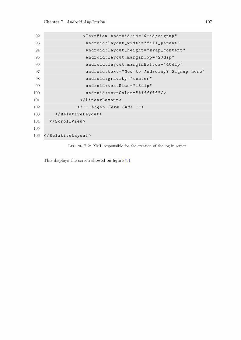
Chapter 7. Android Application 107
92 <TextView android:id="@+id/signup"
93 android:layout_width="fill_parent"
94 android:layout_height="wrap_content"
95 android:layout_marginTop="20dip"
96 android:layout_marginBottom="40dip"
97 android:text="New to Androiny? Signup here"
98 android:gravity="center"
99 android:textSize="15dip"
100 android:textColor="#ffffff"/>
101 </LinearLayout >
102 <!-- Login Form Ends -->
103 </RelativeLayout >
104 </ScrollView >
105
106 </RelativeLayout >
Listing 7.2: XML responsible for the creation of the log in screen.
This displays the screen showed on figure 7.1

Chapter 7. Android Application 108
Figure 7.1: Login Screen.
7.7.2 Action Bar
Android’s action bar is a window feature that identifies the application and user location
while it also provides actions and navigation modes. This component can be used to
present user actions or global navigation.
Action bars offer consistency on the user interface across the various screens, within an
application. Additionally, since Android devices come in very different screen sizes, the
fact that this feature gracefully adapts into each of those screen sizes, is a very significant
feature. Moreover, since this element is extensively used by many applications, including
applications developed by well-known companies, such as Facebook, Google, Twitter and
so forth, the user does not have to spend time familiarizing himself to this feature.

Chapter 7. Android Application 109
This component can be used when specific UI elements need to be easily accessible by
the user. It can be used to host elements such as share buttons, that enable the users to
share content on famous social network websites, navigation buttons such as back, home
or menu buttons. These buttons seem to be ideally placed inside the action bar, as they
have to be particularly easy to spot. Undoubtedly, the application’s name or the name
of the specific screen or even loading screen icons can be added on this component to
help the user understand the current state in which the application is in.
The only drawback of this component is the fact that it is intended to run on Android 3.0
(API level 11) and above. While Android provides the option to use this component on
older Android versions, there is a limitation on the functionality that can be supported
by them. Since, as we mentioned earlier this application was created while keeping in
mind the fact that it is important to be compatible not just with recent high-end devices
but, with older and more low-end devices as well, it seemed appropriate to create our
own Action bar widget to support the functionality we anticipated, and at the same
time avoid these limitations.
At figures 7.6 various Action Bars are displayed. It is easily noticeable that on the
center of the action bar, the name of the application is positioned. On the left there is
positioned a button that has always exactly the same functionality the hard-key back
button has, which is stopping the execution of the query or going back to the previous
screen or the Main Menu screen. On the right, a button with an extra functionality is
displayed. At times, this button is a log off icon placed there to inform the user that
the application’s state allows the logging of from our system. While on occasions when
log off operations simply cannot be performed (for instance when a transaction with the
web service, or a background operation is taking place) a loading screen icon is displayed
instead.
7.7.3 Canvas
As we have mentioned multiple times, the main purpose of this application is to help the
user operate a sensor network. Two operations are supported. The first one is to detect
outlier nodes within the sensor network and the second one is to execute an aggregation
query and inform the user about the measurements received from the sensor network. In
both these occasions, the user has to be aware of the formed network. During the outlier
detection functionality, the user has to be able to get information such as the outlier
nodes and precisely view how different these nodes are from the neighboring ones. On
the sensor measurement functionality, information about the created tree by the sensor
network, has to be displayed.
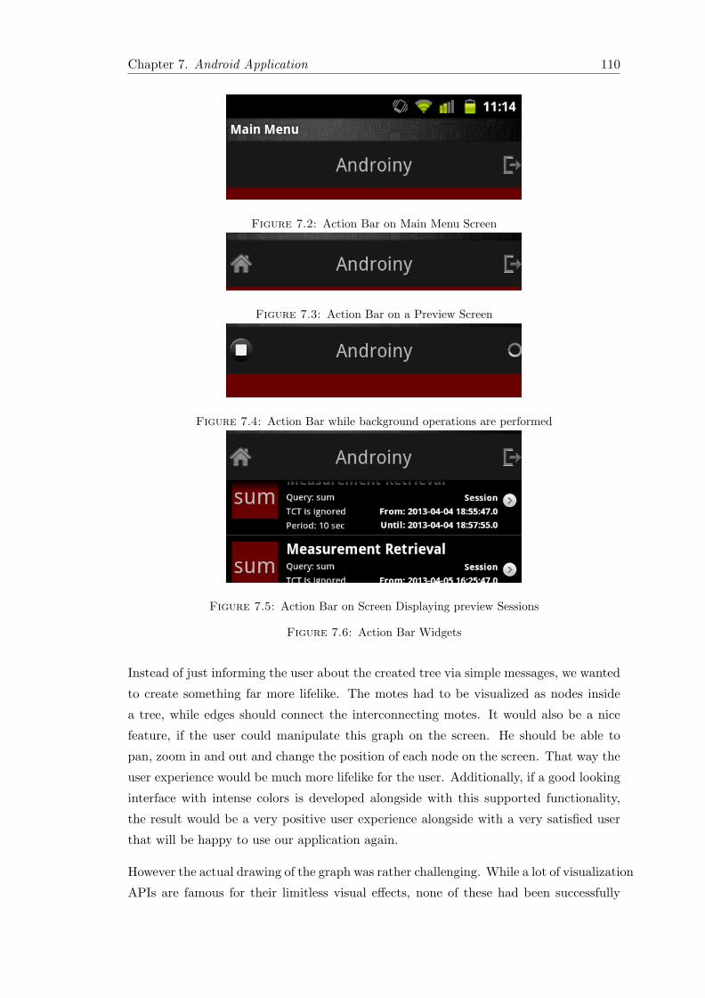
Chapter 7. Android Application 110
Figure 7.2: Action Bar on Main Menu Screen
Figure 7.3: Action Bar on a Preview Screen
Figure 7.4: Action Bar while background operations are performed
Figure 7.5: Action Bar on Screen Displaying preview Sessions
Figure 7.6: Action Bar Widgets
Instead of just informing the user about the created tree via simple messages, we wanted
to create something far more lifelike. The motes had to be visualized as nodes inside
a tree, while edges should connect the interconnecting motes. It would also be a nice
feature, if the user could manipulate this graph on the screen. He should be able to
pan, zoom in and out and change the position of each node on the screen. That way the
user experience would be much more lifelike for the user. Additionally, if a good looking
interface with intense colors is developed alongside with this supported functionality,
the result would be a very positive user experience alongside with a very satisfied user
that will be happy to use our application again.
However the actual drawing of the graph was rather challenging. While a lot of visualization
APIs are famous for their limitless visual effects, none of these had been successfully

Chapter 7. Android Application 111
ported for native Android applications by the time this projected started. Also, the
existing Android API did not provide any tools that could be used for the visualization
of the sensor network graph, and no third party API was able to visualize the sensor
network exactly the way we wanted. Obviously, gaming engines used to develop video
games for Android devices were excluded right away due to the fact that, while they do
enable the developer to create very detailed graphics, the overall size of the application
would be too big for our needs. After all, we should be able to run this application not
only on high powered phones but on middle and low-ranged devices as well. Last but
not least, several javascript libraries could be used, but that would create an additional
load to the very limited bandwidth of the mobile devices. Additionally, many of those
could not be rendered correctly on older devices.
Sadly, we had to create the graphics on our own again. Android API provides a
framework API that enables the drawing of 2D shapes. That way custom low-level
graphics could be rendered into a canvas. It should be mentioned that this part was
extremely hard to implement, because we could not use a middle layer that would
be responsible for the creation of the graphics and the animations using simple calls.
Everything should be performed manually. We had to draw simple circles (used to
represent the motes) on a canvas and display it on the fly while at the same time
animations had to be implemented to provide feedback on the users’ actions.
Every time the user decided to execute a query on the sensor network, and the sensor
network responded via the web service with all the necessary information about the
specifics of the formed tree or graph, an actual representation of this tree or graph had
to be displayed on the screen. This means that during this transaction the Android
application had to create the shapes that represented the motes, and each of those had
to be positioned using specific coordinates into the canvas. The radius of the nodes and
the exact coordinates had to be specifically selected in a way that would not let the
nodes appear outside of the visible canvas, while at the same time, if a tree was shown
the user had to be able to see from the visualization the exact depth it had on that
tree. Additionally, special care should be given in order to avoid two or more nodes
appearing on top of each other. The fact that this application is supposed to run on
Android devices with very different screen sizes, and the fact that the number of nodes
can change drastically from the first execution to the next, made the drawing of this
graph particularly challenging.
Furthermore, an actual animation had to be performed. When the user chooses to pan
the screen a sensor actually tracks the movement of his finger and computes exactly
how fast or slow and in which direction the finger is ”traveling” in order to animate
the movement of these nodes to the same direction. In order to do this efficiently,

Chapter 7. Android Application 112
some sort of sampling was implemented. Instead of endlessly monitoring the movement
and changing the coordinates of each of these nodes and edges, which would have been
extremely power consuming, a simple timer was used that gets fired periodically every
a couple of hundred milliseconds and computes the difference between the last X-Y
coordinates of the finger and the newest ones. Of course the coordinates of the drawn
elements are changed accordingly, thus creating the illusion of animation.
Something similar was implemented to enable the zoom-in and zoom-out effect. A very
famous gesture that is extensively used on multi-touch screens, is the pinch-to-zoom
gesture. During this gesture, the user uses two fingers to zoom in or out of the displaying
graphics. In order to zoom in, the user’s two fingers draw away from each other and
the exact opposite is performed to zoom out. This gives a feeling of direct manipulation
on virtual objects. This gesture along with the panning gesture, gives the illusion of
manipulating digital shapes as if they were real-life objects placed upon a surface. Since
Android 1.6 multi-touch gestures are allowed, so we added this feature to make the user
experience better. However, we had to use the canvas to visualize this action, so we had
to manually count the distance that the two fingers ”traveled” and use this number to
manually change the sizes of the lines and the radius of the circles.
Figures 7.7 and 7.8 show some of the drawings on the canvas.
Figure 7.7: Canvas Drawings for Sensor Measurements

Chapter 7. Android Application 113
Figure 7.8: Canvas Drawings for Outlier Detection
7.7.4 AChartEngine - A Charting Library for Android Applications
AChartEngine is a charting library available for use in Android Applications. It supports
all the Android SDK versions starting from 1.6. Since as we mentioned versions prior to
Android 1.6 do not support pinch to zoom gestures, it displays zoom in and out buttons
to cover this functionality. By the time these words were written the devices that used
a version of Android from 1.6 and above were more than 99% in a global scale.
Adding charting to an Android application with AChartEngine, is as simple as adding
the achartengine-x.y.z.jar to the application classpath and start coding against its APIs.
The jar file is only 110 KB in size, which is quite a small footprint for an Android
application. However, AChartEngine offers support for many chart types.
AChartEngine currently supports the following chart types:
• Line Chart
• Area Chart
• Scatter Chart
• Time Chart

Chapter 7. Android Application 114
• Bar Chart
• Pie Chart
• Bubble Chart
• Doughnut Chart
• Range (high-low) Bar Chart
• Dial Chart / Gauge
• Combined (any combination of Line, Cubic Line, Scatter, Bar, Range Bar, Bubble)
Chart
• Cubic Line Chart
All the above supported chart types can contain multiple series, can be displayed with
the X axis horizontally or vertically and support many other custom features. The model
and the graphing code is well optimized such as it can handle and display huge number
of values.
In figures 7.9 and 7.10 some examples can be viewed that show the potential of this
charting library.
Figure 7.9: AChartEngine examples for mobile phone

Chapter 7. Android Application 115
Figure 7.10: AChartEngine examples for tablet.
Figures 7.11, 7.12, 7.13 show how the sensor measurements are being displayed. Since
we wanted to have as much space as possible for these screens, we chose to display these
images on full-screen. This means that the notification bar which usually appears on
top of the screen is now hidden. Since the user wants to be able to view these graphs
with as many details as possible, and since this application can be executed even on
devices with screens sizes less than 3 inches, it appeared to be a good idea to display
these activities on full screen. After all, it is important to draw the attention of the
user to the measurements while executing a query. If the user ends the execution of a
query and decides to return to the Main menu, the screen will restore its size allowing
the notification bar to be viewed again.

Chapter 7. Android Application 116
Figure 7.11: Downloading Sensor Measurements.
Figure 7.12: Execution of a Summary Query

Chapter 7. Android Application 117
Figure 7.13: Execution of a Count Query
7.8 Summary
To sum up, the client application is perhaps the most important component of our
system. While the code itself is not as challenging as the TinyOS application (even if
the overall number of lines was extremely high when compared to the web service or the
TinyOS application), there were many aspects that had to be taken into consideration.
Firstly, the look and feel of the application had to be appealing. It is important to make
the user feel satisfied after using our application, so we had to make sure that warm,
and cheerful colors were used instead of cold or dark colors which are known to generate
negative emotions. Apart from good-looking, the application had to be useful. Users
are expected to operate a sensor network while on the go, so it is very important to
have an easy-to-use interface. In order to achieve this, we used graphic elements that
are already well-known to Android users as they have been used extensively on other
famous Android applications.
Furthermore, it seemed to be particularly important to make the application fast and
responsive. It is important to avoid latency and the same applies to freezes. This is
especially true when the operator is in a hurry, or trying to multitask. Therefore, we
had to make sure that the exchanging messages had to be limited in size and frequency.

Chapter 7. Android Application 118
When the requirements of the application would not let as avoid big messages, caching
mechanisms were implemented. That way we made sure that the future messages would
be far smaller in size. While in case the frequency, in which messages were transmitted
could not be limited, we chose to perform many of these exchanges on the background
and store the received data locally on the device, before they were actually needed. It
is noteworthy that all of this takes place without bothering the user, or distracting him
by showing annoying pop up loading screens.

Chapter 8
Conclusion
8.1 Summary
In this thesis implementation, we created a complete system that enables the manipulation
of a sensor network using a mobile application. The user of this system is able to
execute operations such as simple sensor measurement retrievals or outlier detection
functionalities, without having to deal with bloated software that requires advanced
programming skills to run. Additionally, while several applications have been developed
in the past, enabling the direct manipulation of a sensor network, neither of them was
free from certain limitations.
The vast majority of these applications is intended to run on older versions of the
Windows operating system. Undoubtedly, there were some obvious restrictions that
arose from this fact. The user had to specifically install outdated versions of an operating
system he would not use for anything else. Dual/Triple-booting, installations of virtual
machines and other complicated operations had to be performed in order for him to be
able to operate a simple sensor network. Apart from that, he was forced to sit behind a
screen in order to operate on the sensor network since Windows is a desktop operating
system.
These limitations, certainly do not apply to our system. Firstly, the client program
used by the end user to enable him interact with our system is an Android application.
This application was developed while keeping in mind that it had to run flawlessly both
on older and newer versions of Android. Additionally, since Android is a very popular
operating system with millions of activations per day, it is rather self-explanatory that
the target audience is particularly big in number, so there should not be any real
limitations there. It is worth mentioning that, the fact that Android is such a successful
119

Chapter 8. Conclusion 120
Figure 8.1: Architecture of the Implemented System.
operating system, works in our favor. A new cheap Android device can be purchased in
a price lower than that of a sensor mote. This is far cheaper than buying a brand new
computer, so there is also a certain advantage on this part too.
Perhaps the most important advantage of this system is the mobility factor. The users
can be virtually anywhere and still be able to use our system, provided that there is an
internet connection. The fact that this system is using a web service, as an intermediate
level between the Android application and the actual sensor network can verify the
flexibility that comes with our system. The web service also guarantees the security of
our system, since the client cannot not operate directly on the sensor network. That
way several activities performed by potential hackers with intentions to cause problems
to our system, are limited. Additionally, since this is a SOAP application, there is
literally no limitations concerning the operating system the server uses. The web service
is hosted on conventional HTTP servers, such as Glassfish or Tomcat which run both
on Windows and Linux operating systems.

Chapter 8. Conclusion 121
8.2 Future Work
The work performed in the context of this thesis implementation can be used as the
base for a several future implementations. some of which are listed below.
8.2.1 Web Application
While this system is natively supported by one of the most popular mobile operating
systems, it is again subjected to limitations. In order for someone to use it, he has to
own an Android device. However with minor work, a web interface of this system can
be implemented in order for it to be supported by any device with internet access. The
fact that the web service was implemented by an extensively used SOAP framework can
act in our favor. An auto-generated API created by this framework can be used to link
this potential web client with the web service and the sensor network.
The only thing the potential developer has to do in order to implement this web client
is to just use this system and build upon it. By utilizing the functions and messages
described in the WSDL file of this web service, he can actually interact with the sensor
network. Obviously, in the same way, native clients intended to run on other operating
systems can also be implemented. Since the messages are transmitted using SOAP and
the actual useful information is in XML, it means that clients can use them regardless
of the programming language used for their implementation.
8.2.2 Limit Bandwidth - Use Cache
While several actions have been performed in order to avoid the unnecessary transactions
of the client with the web service, some additional work can also be performed. For the
time being, SQLite databases have been used to store data such as avatar pictures,
recently executed queries and so forth. A smart system can be implemented to perform
these transactions before these actual data are requested. For example background
operations could be used when the device is connected to a Wi-Fi network to make a
complete copy of the data related to a specific user, that could be previewed when the
device does not have internet access.
8.2.3 Additional Functionality for the Sensor Network
While two sensor network applications have been used by this system, additional functionality
can be added in the future. Furthermore, expansion of the supported applications

Chapter 8. Conclusion 122
can also be performed. For example a ”group by” functionality can be added. With
this functionality, the user will be able to place sensors on different environments (e.g.
different rooms) and be able to view the the conditions in each of these environments
separately.

Bibliography
[1] AChartEngine. Achartengine is a charting library for android applications.
Available online at: https://code.google.com/p/achartengine/ and http://
www.achartengine.org/.
[2] Sabbas Burdakis and Antonios Deligiannakis. Detecting outliers in sensor networks
using the geometric approach. In Kementsietsidis and Salles [7], pages 1108–1119.
[3] Nicolas Burri, Roland Flury, Silvan Nellen, Benjamin Sigg, Philipp Sommer, and
Roger Wattenhofer. Yeti: an eclipse plug-in for tinyos 2.1. In David E. Culler, Jie
Liu, and Matt Welsh, editors, SenSys, pages 295–296. ACM, 2009.
[4] David E. Culler. Tinyos: Operating system design for wireless sensor networks. Only
available online: http://www.sensorsmag.com/networking-communications/
tinyos-operating-system-design-wireless-sensor-networks-918.
[5] CyanogenMod. Cyanogenmod (pronounced sigh-an-oh-jen-mod), is a customized,
aftermarket community based firmware distribution for several android devices.
Only available online: http://www.cyanogenmod.com/.
[6] IndiaNIC. The 2012 smartphone users statistics & growth in the united states of
america. Only available online: http://www.test.org/doe/, 8 2012.
[7] Anastasios Kementsietsidis and Marcos Antonio Vaz Salles, editors. IEEE 28th
International Conference on Data Engineering (ICDE 2012), Washington, DC,
USA (Arlington, Virginia), 1-5 April, 2012. IEEE Computer Society, 2012.
[8] Philip Levis and David Gay. TinyOS Programming. Cambridge University Press,
New York, NY, USA, 1st edition, 2009.
[9] Samuel Madden, Michael J. Franklin, Joseph M. Hellerstein, and Wei Hong. Tag:
a tiny aggregation service for ad-hoc sensor networks. SIGOPS Oper. Syst. Rev.,
36(SI):131–146, December 2002.
123

Bibliography 124
[10] Jack M. Maness, Tomasz Miaskiewicz, and Tamara Sumner. Using personas to
understand the needs and goals of institutional repository users. Available online
at: http://www.dlib.org/dlib/september08/maness/09maness.html.
[11] Mike Rozlog. Rest and soap: When should i use each (or both)? Available online
at: http://www.infoq.com/articles/rest-soap-when-to-use-each.
[12] Mohamed A. Sharaf, Jonathan Beaver, Alexandros Labrinidis, and Panos K.
Chrysanthis. Tina: a scheme for temporal coherency-aware in-network aggregation.
pages 69–76, 2003.
[13] Brian Suda. Soap web servcie implementation. Master’s thesis, The University of
Edinburgh, 11 2003.
[14] TinyOS. Event-based operating environment/framework designed for use with
embedded networked sensors, to support concurrency intense operations needed
by. Only available online: http://www.tinyos.net/.
[15] wikipedia. Three mile island accident. Available online at: http://en.wikipedia.
org/wiki/Three_Mile_Island_accident.