Embed Size (px)
Citation preview
METALURGIJA 45 (2006) 4, 307-312 307
M. Jurković et al.: AN ANALYSIS AND MODELLING OF SPINNING PROCESS WITHOUT ...
Received - Primljeno: 2003-12-24Accepted - Prihvaćeno: 2005-12-25
Preliminary Note - Prethodno priopćenje
iSSN 0543-5846METABk 45 (4) 307-312 (2006)
UDC - UDK 621.983.3:621.774.7:62–462:621.7.016.3:519.863=111
M. Jurković, Z. Jurković, M. MAhMić
M. Jurković, Z. Jurković, Faculty of Engineering university of rijeka, Croatia, M. Mahmić, Faculty of Technical Engineering university of Bihać, Bosnia and herzegovina
INTRODUCTION
The modelling of spinning process is similarly to the process of deep drawing. The workpiece is flat blank.
it is obtained by this processing through simple pre-ssing roller the parts of complex form of good mechanical characteristics and surface which quality is near to the quality obtained after grinding.
it can be obtained the different axial-symmetrical parts. The working parts are divided to symmetrical, conical with curved drawing and combined parts. The spinning process doesn’t enable to produce of unsymmetrical parts [1 - 7].
Tool design that are used for spinning processing is very simple, that secure smaller price and longer the time of explotation life. The same tools can be used for indivi-dual operations at the different parts producing.
THEORETICAL BASIS OF SPINNING PROCESS
At the procedure of metal processing through spinning is the main motion circular and it is made by workpiece
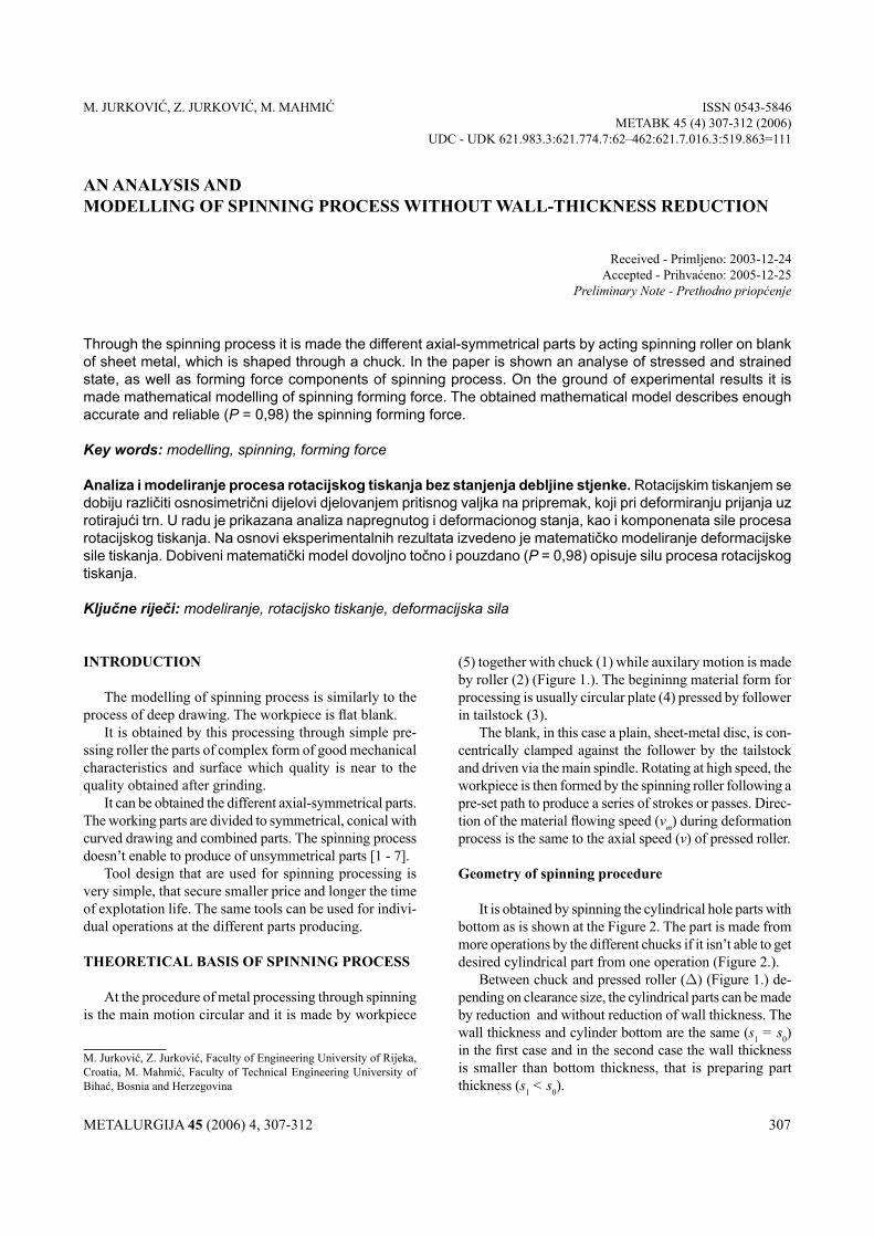
(5) together with chuck (1) while auxilary motion is made by roller (2) (Figure 1.). The begininng material form for processing is usually circular plate (4) pressed by follower in tailstock (3).
The blank, in this case a plain, sheet-metal disc, is con-centrically clamped against the follower by the tailstock and driven via the main spindle. rotating at high speed, the workpiece is then formed by the spinning roller following a pre-set path to produce a series of strokes or passes. Direc-tion of the material flowing speed (vm) during deformation process is the same to the axial speed (v) of pressed roller.
Geometry of spinning procedure
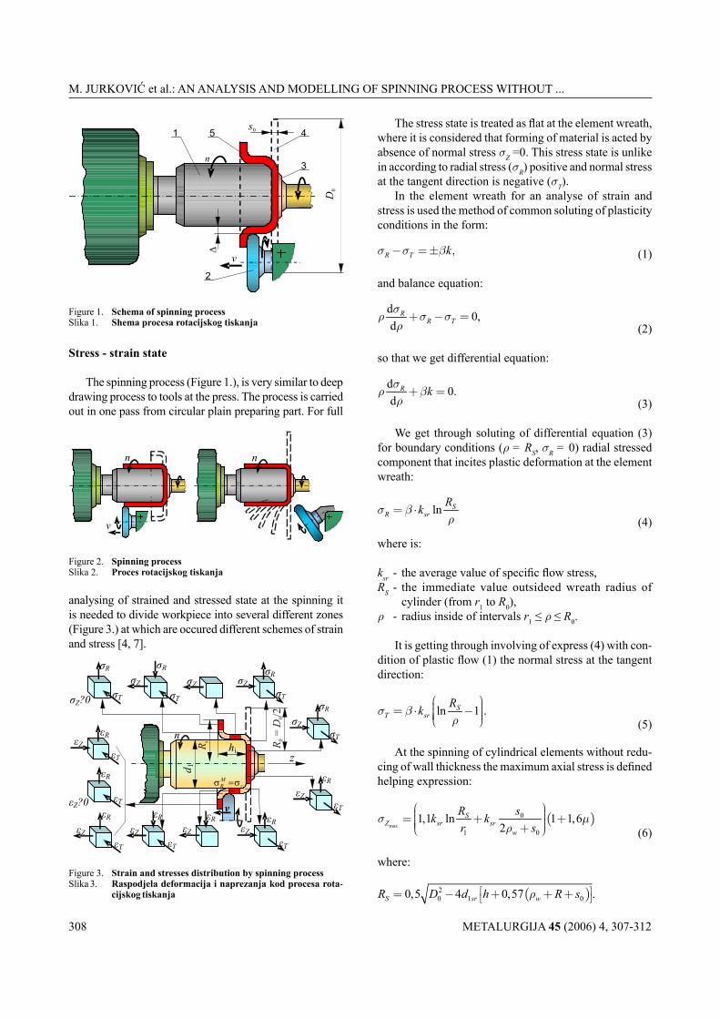
it is obtained by spinning the cylindrical hole parts with bottom as is shown at the Figure 2. The part is made from more operations by the different chucks if it isn’t able to get desired cylindrical part from one operation (Figure 2.).
Between chuck and pressed roller (D) (Figure 1.) de-pending on clearance size, the cylindrical parts can be made by reduction and without reduction of wall thickness. The wall thickness and cylinder bottom are the same (s1 = s0) in the first case and in the second case the wall thickness is smaller than bottom thickness, that is preparing part thickness (s1 < s0).
AN ANALYSIS ANDMODELLING OF SPINNING PROCESS WITHOUT WALL-THICKNESS REDUCTION
Through the spinning process it is made the different axial-symmetrical parts by acting spinning roller on blank of sheet metal, which is shaped through a chuck. In the paper is shown an analyse of stressed and strained state, as well as forming force components of spinning process. On the ground of experimental results it is made mathematical modelling of spinning forming force. The obtained mathematical model describes enough accurate and reliable (P = 0,98) the spinning forming force.
Key words: modelling, spinning, forming force
Analiza i modeliranje procesa rotacijskog tiskanja bez stanjenja debljine stjenke. Rotacijskim tiskanjem se dobiju različiti osnosimetrični dijelovi djelovanjem pritisnog valjka na pripremak, koji pri deformiranju prijanja uz rotirajući trn. U radu je prikazana analiza napregnutog i deformacionog stanja, kao i komponenata sile procesa rotacijskog tiskanja. Na osnovi eksperimentalnih rezultata izvedeno je matematičko modeliranje deformacijske sile tiskanja. Dobiveni matematički model dovoljno točno i pouzdano (P = 0,98) opisuje silu procesa rotacijskog tiskanja.
Ključne riječi: modeliranje, rotacijsko tiskanje, deformacijska sila
METALURGIJA 45 (2006) 4, 307-312308
M. Jurković et al.: AN ANALYSIS AND MODELLING OF SPINNING PROCESS WITHOUT ...
Stress - strain state
The spinning process (Figure 1.), is very similar to deep drawing process to tools at the press. The process is carried out in one pass from circular plain preparing part. For full
analysing of strained and stressed state at the spinning it is needed to divide workpiece into several different zones (Figure 3.) at which are occured different schemes of strain and stress [4, 7].
The stress state is treated as flat at the element wreath, where it is considered that forming of material is acted by absence of normal stress sZ =0. This stress state is unlike in according to radial stress (sR) positive and normal stress at the tangent direction is negative (sT).
in the element wreath for an analyse of strain and stress is used the method of common soluting of plasticity conditions in the form:
,R T kσ σ β− =± (1)
and balance equation:
d 0,d
RR T
σρ σ σρ+ − =
(2)
so that we get differential equation:
d 0.d
R kσρ βρ+ =
(3)
We get through soluting of differential equation (3) for boundary conditions (r = RS, sR = 0) radial stressed component that incites plastic deformation at the element wreath:
ln SR sr
Rkσ βρ
= ⋅ (4)
where is:
ksr - the average value of specific flow stress,RS - the immediate value outsideed wreath radius of
cylinder (from r1 to R0),r - radius inside of intervals r1 ≤ r ≤ R0.
it is getting through involving of express (4) with con-dition of plastic flow (1) the normal stress at the tangent direction:
ln 1 .ST sr
Rkσ βρ
= ⋅ − (5)
At the spinning of cylindrical elements without redu-cing of wall thickness the maximum axial stress is defined helping expression:
( )max
0
1 0
1,1 ln 1 1,62
SZ sr sr
w
R sk kr s
σ µρ
= + + + (6)
where:
( )20 1 00,5 4 0,57 .S sr wR D d h R sρ = − + + +
METALURGIJA 45 (2006) 4, 307-312 309
M. Jurković et al.: AN ANALYSIS AND MODELLING OF SPINNING PROCESS WITHOUT ...
Maximum axial stress ( )max
,Zσ obtained by h = 0.
Degree of deformation
The fitted relative strain at the element wreath are:- at the tangent direction:
2 2 20
1,T
SR Rρ
ερ
= −+ − (7)
- at the radial direction (direction of sheet of metal thic-kness):
1 2ln,
2 ln
S
R TS
R
Rρε ε
ρ
−= ⋅−
(8)
- at the axial direction:
( ).Z T Rε ε ε=− + (9)
At the immediate strained zone it is normal strains under pressed roller:
1 1,Ti
da
ε = −
1 0
0
0,R Ss s
sε ε
−= = ≈
( )11
2.i i
Z hi
h a da d
ε ε− −
= =− (10)
where:
( )214 0,75i ia d d h R= + + - the immediate value of
workpiece diameter which was deformed in the cylinder of hi height.
Logarithmic strain at the part under pressed roller are defined by expressions:
1 1
0 1
2ln , ln 0, ln .iT R Z
i i
hd sa s a d
ϕ ϕ ϕ= = ≈ =− (11)
Forming forces of the spinning process
The axial components of force is determined by expression:
max,Z A Z ZF F Aσ= = ⋅ (12)
unless the contact surface of axial force:
0 02 2 .Z wvA ls s dn
= = ⋅ (13)
on the basis of plastic flowing condition the maximum radial strain expresses:
max1,15R Z srkσ σ= + (14)
and
2R wv vA dn n
= ⋅ (15)
or the maximum component of force is:
max max.R R RF Aσ= ⋅ (16)
owing to simplifying the state of deformation it is taken into account the plane state of deformation and the tangent stress is:
max
1,152 2
srZ RT
kσ σσ
+= =
(17)
and tangent components of force:
max maxT T TF Aσ= ⋅ (18)
where the contact surface is:
01 2 .2T w
vA sn
ρ= ⋅ (19)
The experimental researchings are shown that the maximum radial force occurs immediatelly at the end of spinning of cylindrical part. The axial stress in this moment equals zero (sZ = 0). Total force:
2 2 2 .A R TF F F F= + + (20)
THE EXPERIMENTALANALYSIS OF THE PROCESS
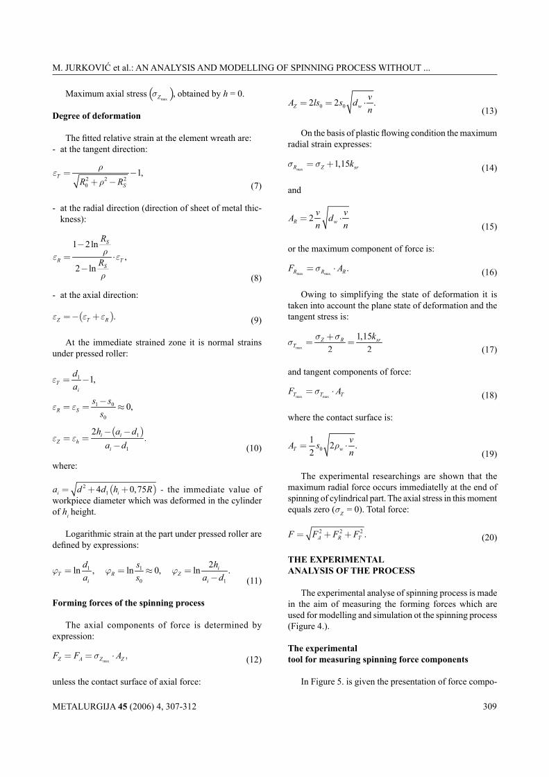
The experimental analyse of spinning process is made in the aim of measuring the forming forces which are used for modelling and simulation ot the spinning process (Figure 4.).
The experimentaltool for measuring spinning force components
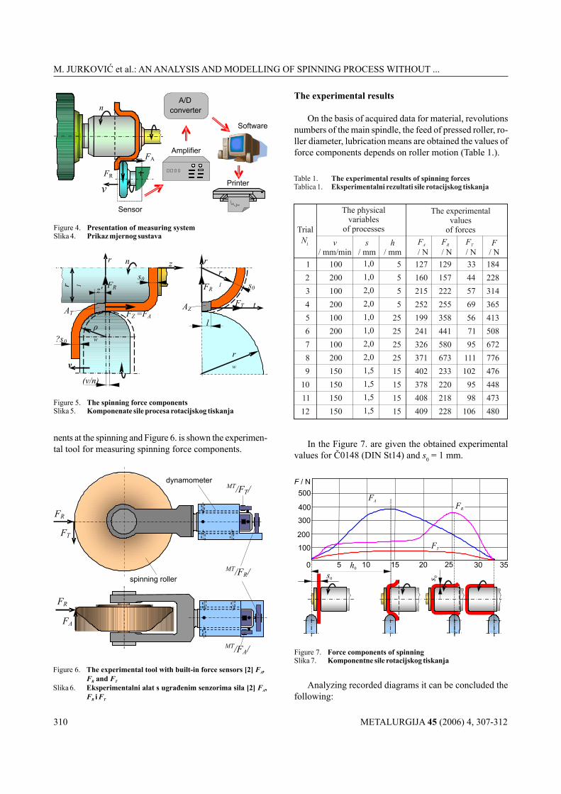
in Figure 5. is given the presentation of force compo-
METALURGIJA 45 (2006) 4, 307-312310
M. Jurković et al.: AN ANALYSIS AND MODELLING OF SPINNING PROCESS WITHOUT ...
nents at the spinning and Figure 6. is shown the experimen-tal tool for measuring spinning force components.
The experimental results
on the basis of acquired data for material, revolutions numbers of the main spindle, the feed of pressed roller, ro-ller diameter, lubrication means are obtained the values of force components depends on roller motion (Table 1.).
in the Figure 7. are given the obtained experimental values for Č0148 (DiN St14) and s0 = 1 mm.
Analyzing recorded diagrams it can be concluded the following:
METALURGIJA 45 (2006) 4, 307-312 311
M. Jurković et al.: AN ANALYSIS AND MODELLING OF SPINNING PROCESS WITHOUT ...
- the pressed roller moves during the process by constant speed,
- the tangent component has nearly constant value during the process,
- the maximum value of radial force occurs at the end of the process,
- the decreasing of axial force after reaching of maximum is stepped (at the cylindrical parts obtained through com-bined action) but at the parts obtained without reducing the decreasing of axial force is extended.
FORCE MODELLING
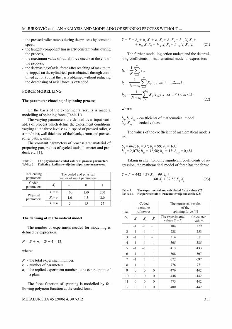
The parameter choosing of spinning process
on the basis of the experimental results is made a modelling of spinning force (Table 1.).
The varying parameters are defined over input vari-ables of process which define the experiment conditions varying at the three levels: axial speed of pressed roller, v /(mm/min), wall thickness of the blank, s /mm and pressed roller path, h /mm.
The constant parameters of process are: material of preparing part, radius of cycled tools, diameter and pro-duct, etc. [1].
The defining of mathematical model
The number of experiment needed for modelling is defined by expression:
N = 2k + n0 = 23 + 4 = 12,
where:
N - the total experiment number,k - number of parameters,n0 - the replied experiment number at the central point of
a plan.
The force function of spinning is modelled by fo-llowing polynom function at the coded form:
Y = F = b0 + b1 X1 + b2 X2 + b3 X3 + b12 X1 X2 + + b23 X2 X3 + b13 X1 X3 + b123 X1 X2 X3 (21)
The further modelling action understand the determi-ning coefficients of mathematical model to expression:
01
1 ,N
jj
b yN =
= ∑
0 1
1 , za 1,2,..., ,N
i ij jj
b X y i kN n =
= =− ∑
0 1
1 , za 1 .N
im ij mj jj
b X X y i m kN n =
= ≤ < <− ∑ (22)
where:
b0, bi, bim - coefficients of mathematical model,Xij, Xmj - coded values.
The values of the coefficient of mathematical models are:
b0 = 442; b1 = 37; b2 = 99; b3 = 160;b12 = 2,078; b23 = 32,58; b13 = 13; b123 = 0,481.
Taking in attention only significant coefficients of re-gression, the mathematical model of force has the form:
Y = F = 442 + 37 X1 + 99 X2 + + 160 X3 + 32,58 X2 X3 (23)
METALURGIJA 45 (2006) 4, 307-312312
M. Jurković et al.: AN ANALYSIS AND MODELLING OF SPINNING PROCESS WITHOUT ...
List of symbols
n - revolutions numbers of chuck /min–1
v - axial speed of pressed roller /(mm/min) vm - the material flowing speed /(mm/min) D0 - diameter of workpiece (blank diameter)
/mm d1 - diameter of rotary chuck (chuck diame-
ter) /mm r1 - chuck radius /mm d - diameter of finished product /mm s - wall thickness /mm s0 - initial sheet thickness /mm dw - diameter of pressed roller /mm rw - roller radius /mm h - pressed roller path /mm l - spinning length /mm d1sr - the immediate diameter of workpiece
wreath /mm R0 - blank radius /mm RS - the immediate value outsideed wreath
radius of cylinder (from r1 to R0) /mm ai - the immediate value of workpiece
diameter which was deformed in the cylinder of hi height /mm
v/n - spinning feed of roller /mm·rev–1
k - number of parameters ksr - the average value of flow stress /Pa Ds - absolute reducing of wall thickness
/mm a0 - angle of chuck /° a - angle of pressed roller /° b - Lode coefficient (b = 1,0 to 1,55) m - coefficient of friction r - radius inside of intervals r1 ≤ r ≤ R0
/mm sR, sZ, sT - radial, axial and tangent stress /Pa
max max max, , R Z Tσ σ σ - maximum stresses in radial, axial and
tangent direction /Pa eR, eZ, eT - the relative strains in radial, axial and
tangent direction jR, jZ, jT - logarithmic strains FR, FZ, FT - the force components in radial, axial and
tangent direction /Nmax max max
, , R Z TF F F - maximum force in radial, axial and tangent direction /N
F - total force /N AR, AZ, AT - the pressed contact surface at the radial,
axial and tangent direction / mm2
Xij, Xmj - coded values n0 - the replied experiment number at the
central point of a plane b0, bi, bim - coefficients of mathematical model N - the total experiment number MT - strain gages
REFERENCES
[1] M. Jurković, Mathematical Modelling and optimization of Ma-chining Processes, Faculty of Engineering, university of rijeka, rijeka, 1999, p. 151 - 176 and 335 - 386.
[2] D. Lazarević, Sile pri rotacionom izvlačenju koničnih delova, Xviii Savetovanje proizvodnog mašinstva Jugoslavije, Mašinski fakultet, Niš, 1984, p. 363 - 377.
[3] M. Jurković, Band Cross Section Geometry in the Function of Thermo-Mechanical Factors and Stress State of Cold Forming Processes, Dissertation thesis, 1981, p. 148 - 192.
[4] D. Lazarević, v. Stoiljković, Naponsko - deformaciono stanje i sile pri rotacionom izvlačenju cilindričnih delova bez redukcije debl-jine zida, Xvii Savetovanje proizvodnog mašinstva Jugoslavije, Titograd, 1983, p. iii19 - iii22.
[5] k. Lange, Lehrbuch der umformtechnik, Band 3, Blechbearbeitung, Springer-verlag, Berlin-heidelberg New York, 1975, p. 1 - 456.
[6] M. Jurković, Z. Jurković, Direct Determining of Stress and Friction Coefficient on the Contact Surface of Tool and Workpiece, Proc. 1st int. Conf. iCiT ’97, 1 (1997), Ljubljana - Maribor, p. 127 - 132.
[7] N. i. Mogiljnji, rotacionaja vytjažka oboločkovyh detalej na stan-kah, Mašinostroenie, Moskva, 1983, p. 1 - 190.
The coefficient of multiple regression R = 0,993 shows very good correlation between varying Xi and spinning force Fj.
The mathematical model (23) enough correctly and reli-able (P = 0,98) describes the process force of spinning inside the space of applied experiment what shows the comparing of experimental and calculated values (Table 3.).
Encoding the mathematical model (23) is obtained the physical mathematical model of the spinning force in the form of:
Y = – 59,39 + 0,74v + 100,26s + 6,226h + 6,516s·h (24)
CONCLUSIONS
in according to deep drawing this procedure has de-fined advantages:- enable producing of complex products,- deformation is made in the part under pressed roller,
unless at deep drawing at the whole volume of part countour,
- the tools are more simple design than the tools of deep drawing,
- the tool life is longer and tool costs are smaller,- smaller forming force,- the tool is flexibile because the same can be used for
different parts producing.
The ground failures are:- unsymetrical parts cann’t be produce,- smaller production in according to deep drawing.
The mathematical modelling of the force of spinning eno-ugh correctly and reliable describes forming force, that are confirmed by obtained model of the that has reliability P = 0,98 and the coefficient of multiple regression R = 0,993.