Embed Size (px)
Citation preview

Mechanics & Industry 21, 402 (2020)© AFM, EDP Sciences 2020https://doi.org/10.1051/meca/2019086
Mechanics&IndustryAvailable online at:
www.mechanics-industry.org
REGULAR ARTICLE
Study on optimization of thermal spinning processof accumulator shellBin Li1,2, Yunan Li1,2, Peihao Zhu1,2,*, Wenpeng Ma1,2, Yinhong Xiao1,2, and Xiang Li1,2
1 Tianjin Key Laboratory for Advanced Mechatronic System Design and Intelligent Control, School of Mechanical Engineering,Tianjin University of Technology, Tianjin 300384, PR China
2 National Demonstration Center for Experimental Mechanical and Electrical Engineering Education, Tianjin University ofTechnology, Tianjin, PR China
* e-mail: z
Received: 18 May 2019 / Accepted: 15 November 2019
Abstract. In view of the shortcomings of the existing hot spinning process technology of the accumulator shell, amethod for optimizing themulti-spinning process parameters is proposed. The Johnson-Cook constitutivemodelof the accumulator shell material – 34CrMo4 alloy steel � was established with its parameters obtainedexperimentally. The finite element simulation was carried out for the hot spinning and closing process. Based onwhich, three parameters with the greatest influence on the spinning formation were studied: spinningtemperature, spindle speed and friction coefficient. Combined with the central composite test, the responsesurface model and the mapping relationship between the three parameters and the maximummises stress as wellas the maximum wall thickness increment of the shell were established. The Pareto optimized solution set wasobtained through multi-objective optimization. Under the condition of not affecting product quality, theoptimized solution with low spinning temperature and high spindle speed is selected to reduce energy loss andimprove work efficiency. The results indicate that the optimized process is experimentally verified to reduce theprocess temperature by nearly 30 °C, and the efficiency is increased by 25%.
Keywords: Accumulator / hot spinning technology / finite element / response surface / multi-objectiveoptimization
1 Introduction
The accumulator is an energy storage device in hydraulicand pneumatic systems that stores or releases thecompressive energy to ensure that the entire system isunder normal pressure. The shell of the accumulator is animportant part, and its manufacturing process is especiallyimportant to ensure the stability of the system transmis-sion [1,2]. Therefore, it is of great significance to study thehot spinning process of the shell for its preparation. Atpresent, the processing method of the accumulator shell isusually welding. However, there are obvious processingdefects in it because stress concentration and cracks oftenoccur at the welding points [3,4], which causes theaccumulator to be scrapped [5,6]. Compared with thetraditional welding process, the spinning process canprepare a seamless accumulator, which fundamentallyavoids the processing defects caused by traditionalprocessing method, improves the accumulator quality
and reduces the rejection rate and the processing cost [7,8].The hot spinning process of the accumulator shellmentioned above is a high-energy process. Due to thecurrent unreasonable process parameters, the effectiveenergy conversion ratio is not high, and most of the energyis lost in the form of heat energy [9–11]. Therefore,optimization of the parameters of the hot spinning processfor the accumulator shell is of vital importance for energysaving and the emission reduction.
At present, hot spinning processing has broad applica-tion prospects in the accumulator shell manufacturingindustry due to the advantages of good metal deformationconditions, high material utilization rate, and significantproduct performance [12,13]. Although the hot spinningprocess has many advantages, there are still processingdefects and deficiencies due to improper process param-eters, such as peeling, corrugation, cracks, pinch instabilityand insufficient surface accuracy that may occur duringspinning [14,15]. Many scholars at home and abroad havestudied the improvement of spinning process parameters inresponse to the above problems. Some scholars optimizethe spinning process parameters by the optimization
2 B. Li et al.: Mechanics & Industry 21, 402 (2020)
algorithms. For example, Zhu [16] transformed multi-objective optimization into single-objective optimizationthrough genetic algorithm, and finally found the optimalparameters to improve the safety of the accumulator.Hashemi Abbas et al. [17] used an adaptive optimizationalgorithm combined with fuzzy logic control and annealingoptimization algorithm to find the optimal pressure loadcurve to prevent wrinkling of the shell casing duringspinning contraction. Yoon et al. [18] used geneticalgorithms in the noise reduction study of accumulatorsto reduce noise while reducing the transmission loss ofenergy to high frequency vibration. In addition, manyscholars use simulation software to analyze the dynamicmodel or numericalmodel of the accumulator, and optimizethe model parameters to achieve the purpose of processparameter optimization. Chen et al. [19] established thedynamic model of accumulator and pipeline throughAMESim software, and analyzed the relevant parametersaffecting the characteristics of the accumulator, optimizedthemodel, and finally optimized the parameters to improvethe stability of the system. Lin et al. [20] studied the finiteelement model of the influence of staggered spinningparameters on the accuracy of parts. The optimizationparameters were obtained based on finite element analysis,which improved the precision of machining. Li et al. [21]used the ABAQUS software to establish a three-dimen-sional model of the part in the forming method ofsimultaneous spinning to produce two conical parts. Theprocessing parameters were determined by metal formingprinciple analysis. Sedighi et al. [22] studied the spinningmanufacturing of aluminum conical tubes, using three-dimensional dynamic explicit model to simulate and studythe strain distribution in the track, and finally found thatthe hardness of the conical tubes increased significantly.Takahashia et al. [23] studied the spinning process ofSUS409 tube, calculated the damage value of the fracturecriterion and the position of themaximumdamage value byestablishing a three-dimensional finite element model, anddetermined the spinning condition without crack. Luo et al.[24] studied the spinning technology of large-componentcomplex thin-walled shells used in aerospace, and proposeda composite spinning process combined with back rolls toestablish roll-type spinning and multi-neck spinning. Theysimulated the influence of different spinning processparameters on the maximum equivalent stress as well asmaximum ellipticity of the sample with the finite elementmodel of press forming, and determined the back rollerspinning process parameters. Xue et al. [25] carried outnonlinear finite element simulation on the neck-spinningprocess, and studied the internal and external stressdistribution of the pipeline deformation zone during themulti-pass shrinkage process. Zhanga [26] proposed aprocess to optimize the spinning compression port, whichreversed the flow direction of the material and the directionof the spinning roller, and found that the internal surfaceprecision was significantly improved. Roy et al. [27] usedthe experimental-numerical method to carry out theintermittent spinning test at room temperature on the6061-0 aluminum alloy gas cylinder, and established anumerical simulation model to obtain the effect of spinningroller path on tube shape and thickness variation.
However, these studies have their shortcomings.Firstly, they only considered the influence of the spinningprocess on the quality parameters of the processedproducts, while ignored that the hot spinning processitself is a highly energy-intensive process and reducing themanufacturing costs is also a strong desire of manufac-turers which should ensure energy-saving manufacturingand avoid the defects of spinning processing. Secondly, anumber of process parameters have an effect on the spinforming. Considering the influence factors of the spinningroller path alone, optimizing the spinning roller path is notenough to characterize the optimization of the entire hotspinning process. Finally, the accurate numerical model ofthe accumulator material was not tested. It may result inan optimization result that is not meaningful to actualproduction guidance. Therefore, this paper makes aHopkinson pressure bar experiment to accurately deter-mine the constitutive model of the material for theaccumulator material. For the problem of multiplespinning process parameters, the response surface-basedcentral composite test [28] is used to determine the keyinfluence parameters, and then apply multi-objectiveoptimization algorithm for process parameter optimiza-tion. Under the premise of accurate modeling, theparameters are optimized for the high energy consumptionin production and the complexity of multi-parameterproblems, which reflects the novelty of this research.
In view of the high energy consumption and lowproduction efficiency, which is common in the hot spinningprocess of accumulator shell [29,30], the process parametersneed to be optimized to achieve the purpose of energy-saving manufacturing without changing the accumulatorquality. According to the above optimization objectives, anoptimization method of accumulator spinning processparameters is proposed, which includes the followingprocedures: establishing the constitutive model of theaccumulator shell material and the finite element model ofthe neck-spinning, analyzing the response surface relation-ship between parameters, and optimizing the processparameter.
2 Materials and methods
In this section, the method of establishing the Johnson-Cook constitutive model of the material of the accumulatorcasing 34CrMo4 alloy steel, the process of using theobtained model to make the finite element analysis of theneck-spinning, the analysis method of the optimizedparameters and the experimental design of the optimizedparameters are introduced.
2.1 Johnson-Cook constitutive model of 34CrMo4alloy steel
During the process of neck-spinning the accumulator shell,the sample material is often subjected to elastic deforma-tion, large deformation and large strain rate at hightemperature. Therefore, Jonson-Cook constitutive model[31,32] is adopted to consider the influence of variousfactors (strain, strain rate, thermal softening) on the
B. Li et al.: Mechanics & Industry 21, 402 (2020) 3
hardening stress of the sample material. The Jonson-Cookconstitutive model formula [33] is as follows:
s ¼ AþBenP� �
1þ Cln_e_e0
� �1� T � T 0
Tmelt � T 0
� �m� �ð1Þ
where,A is the yield strength under quasi-static conditions,B is the strain hardening parameter, eP is the equivalentplastic strain, n is the hardening index, C is the strain ratestrengthening parameter, _e is the equivalent plastic strainrate, _e0 is the reference strain rate of the material, T0 is theroom temperature, usually 25 °C, Tmelt is the melting pointof the material; m is the thermal softening parameter.
To determine the constitutive model of the 34CrMo4alloy steel, it is necessary to determine A,B,C,n,m informula (1). At room temperature and quasi-static, theJonson-Cook constitutive formula (1) can be rewritten intoformula (2), and the formula (2) can be rewritten asformula (3) by the following formula:
s ¼ AþBenP ð2Þ
lnðs �AÞ ¼ nlnep þ lnB: ð3ÞIt can be seen from formula (3) that the values of A, B
and n in the constitutive model can be obtained byexperiments and data analysis under static conditions. Inorder to obtain the quasi-static mechanical properties ofthe 34CrMo4 alloy steel, experiment is carried out on theCSS electronic universal testing machine. The model of themachine is WEW-300B manufactured by HaochengTechnology Co., Ltd., and the test used a cylindricalsample with a diameter of 10mm and a height of 5mm. Theexperiment is carried out at room temperature (20 °C), andaccording to the national standard GB/T7314-2017 “Metalmaterial compression test method at room temperature”.Ais the initial yield strength of the material at roomtemperature and quasi-static. A can be determined by thetest. The strain and stress values of the material obtainedin the experiment can be used to obtain a fitting curve. Theslope of the fitted curve is n, the intersection with the y-axisis lnB, from which parameters B and n can be obtained.
To determine the parameters C and m in theconstitutive model, the dynamic mechanical test mustbe carried out on the basis of the static parameters. Thedynamic mechanical performance test is carried out withthe Hopkinson pressure bar device. The device is operatedby Beijing Dexing Technology Co., Ltd., China. Thecompany’s productionmodel is ALT1000. The stress-straincurve of the material at different temperatures and strainrates is measured by the device. Considering the mechani-cal properties of 34CrMo4 alloy steel, the cuttingtemperature and the configuration of Hopkinson pressurebar experimental device, it is determined that thetemperature range of the design test is from 950 °C to1150 °C, and the strain rate is from 0.1 s�1 to 6.0 s�1.
The schematic of the Hopkinson pressure bar experi-mental device is pushing the bullet in the gas chamber, thespeed measuring system can measure the speed of thebullet, and the bullet impacts the input rod through the
force transmission to compress the test specimen andfinally to the transmission rod. The strain measurementrecording system records the strain gauge signal [34,35].
According to the incident wave, reflected wave andtransmitted wave measured by the experimental device,the stress wave theory can be used to determine the valuesof strain, strain rate and stress from the formulas (4)–(6).
e ¼ � 2C0
L0
Z t
0
eidt ð4Þ
_e ¼ 2C0
L0er ð5Þ
s ¼ EA
Asee ð6Þ
where, E is the Young’s modulus, A is the cross-sectionalarea, C0 is the elastic wave velocity, L0 is the initial lengthof the sample, As is the cross-sectional area of the sample,ei is the incident strain wave, er is the reflected strain wave,ee is the transmission Strain wave.
In the case of different strain rates at the sametemperature, the constitutive model formula of thematerial can be rewritten as formula (7) as follows:
s
AþBePn� 1 ¼ Cln_e
∗: ð7Þ
The stress-strain relationship with the same tempera-ture and different strain rate can be obtained by theHopkinson pressure bar experiment. The formula (7) canbe used to obtain the fitting curve, where C is the slope ofthe fitting function.
In the case of different strain rates at differenttemperatures, the constitutive formula of the materialcan be rewritten as formula (8) as follows:
lnðAþB epn0 Þ � s
AþB epn0
� �¼ mlnT
∗: ð8Þ
The stress-strain relationship with the same strain rateand different temperature can be obtained by theHopkinson pressure bar experiment. The formula (8) canbe used to obtain the fitting curve, where m is the slope ofthe fitting function.
2.2 Finite element model of spinning
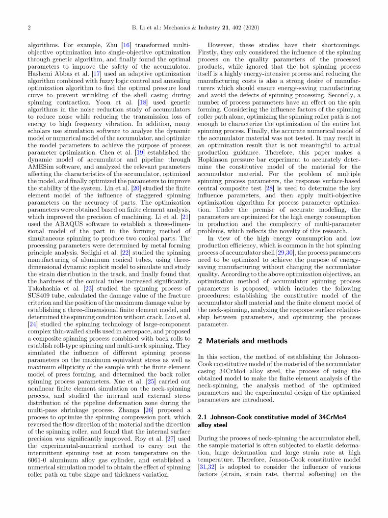
To establish of the finite element model of the accumulatorneck-spinning, it is necessary to analyze the motionrelationship between the spinning roller and the tubebillet. In the actual accumulator spinning process, in orderto process the work-piece that meets the design require-ments, the spinning motion is decomposed into threemotion modes as shown in Figure 1: axial velocity V, itsown rotational angular velocity w1, oscillating motion w2,and w3 is the billet rotation speed. After the actualproduction analysis, the simulation motion parameters
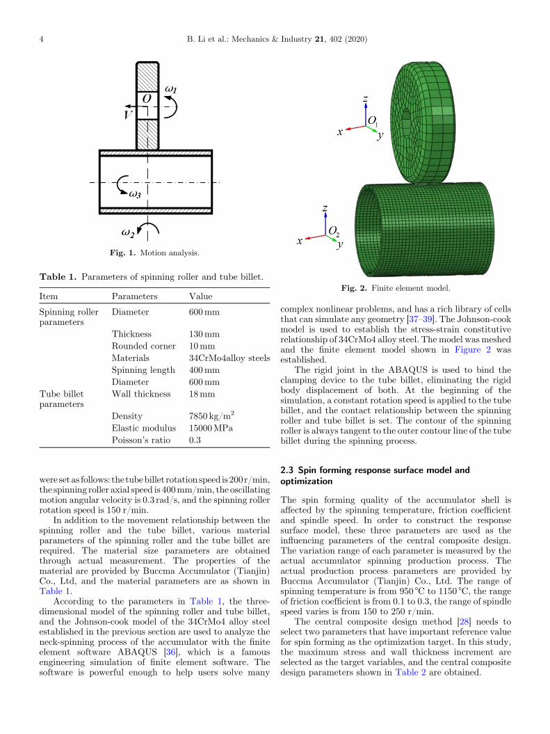
Table 1. Parameters of spinning roller and tube billet.
Item Parameters Value
Spinning rollerparameters
Diameter 600mm
Thickness 130mmRounded corner 10mmMaterials 34CrMo4alloy steelsSpinning length 400mmDiameter 600mm
Tube billetparameters
Wall thickness 18mm
Density 7850 kg/m2
Elastic modulus 15000MPaPoisson’s ratio 0.3
Fig. 1. Motion analysis.
Fig. 2. Finite element model.
4 B. Li et al.: Mechanics & Industry 21, 402 (2020)
were setas follows: thetubebillet rotation speed is200r/min,the spinning roller axial speed is 400mm/min, the oscillatingmotion angular velocity is 0.3 rad/s, and the spinning rollerrotation speed is 150 r/min.
In addition to the movement relationship between thespinning roller and the tube billet, various materialparameters of the spinning roller and the tube billet arerequired. The material size parameters are obtainedthrough actual measurement. The properties of thematerial are provided by Buccma Accumulator (Tianjin)Co., Ltd, and the material parameters are as shown inTable 1.
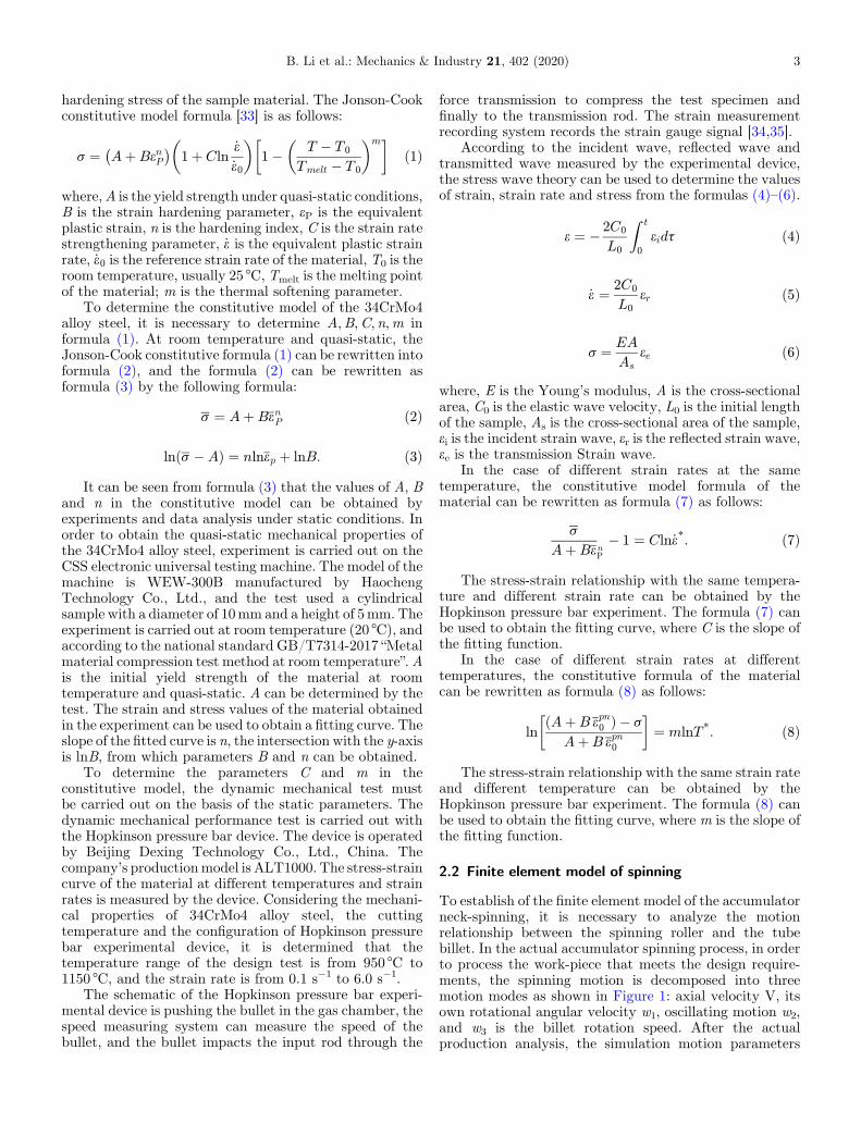
According to the parameters in Table 1, the three-dimensional model of the spinning roller and tube billet,and the Johnson-cook model of the 34CrMo4 alloy steelestablished in the previous section are used to analyze theneck-spinning process of the accumulator with the finiteelement software ABAQUS [36], which is a famousengineering simulation of finite element software. Thesoftware is powerful enough to help users solve many
complex nonlinear problems, and has a rich library of cellsthat can simulate any geometry [37–39]. The Johnson-cookmodel is used to establish the stress-strain constitutiverelationship of 34CrMo4 alloy steel. The model was meshedand the finite element model shown in Figure 2 wasestablished.
The rigid joint in the ABAQUS is used to bind theclamping device to the tube billet, eliminating the rigidbody displacement of both. At the beginning of thesimulation, a constant rotation speed is applied to the tubebillet, and the contact relationship between the spinningroller and tube billet is set. The contour of the spinningroller is always tangent to the outer contour line of the tubebillet during the spinning process.
2.3 Spin forming response surface model andoptimization
The spin forming quality of the accumulator shell isaffected by the spinning temperature, friction coefficientand spindle speed. In order to construct the responsesurface model, these three parameters are used as theinfluencing parameters of the central composite design.The variation range of each parameter is measured by theactual accumulator spinning production process. Theactual production process parameters are provided byBuccma Accumulator (Tianjin) Co., Ltd. The range ofspinning temperature is from 950 °C to 1150 °C, the rangeof friction coefficient is from 0.1 to 0.3, the range of spindlespeed varies is from 150 to 250 r/min.
The central composite design method [28] needs toselect two parameters that have important reference valuefor spin forming as the optimization target. In this study,the maximum stress and wall thickness increment areselected as the target variables, and the central compositedesign parameters shown in Table 2 are obtained.

Table 2. Test parameters of response surface model.
No. The spinningtemperature x1 (°C)
Frictioncoefficient x2
Main spindlespeed x3 (r/min)
Maximumstress y1 (MPa)
Maximum thicknessincrement y2 (mm)
1 1150 0.20 250 290.6 4.62 1050 0.30 250 271.6 5.13 1150 0.30 200 274.2 4.24 1050 0.20 150 282.8 4.55 1050 0.20 200 282.8 4.56 950 0.20 150 317.7 5.47 1050 0.10 250 304.2 4.08 950 0.20 250 321.3 5.59 950 0.30 200 308.7 6.010 950 0.10 200 333.4 5.1
B. Li et al.: Mechanics & Industry 21, 402 (2020) 5
In this paper, the response surface method is used toestablish the mapping relationship between the maximumstress, thickness increment and parameters. There are twocommonly used approximate models in the responsesurface method: the first-order response surface modeland the second-order response surface model. Because ofthe nonlinear relationship between the maximum stress,the thickness increment and the three influencing param-eters, the first-order response surface model cannot satisfythe regression effect. Therefore, this paper adopts second-order response surface model to establish the spin-sleevemodel of the accumulator shell. The second-order responsesurface model expression [40,41] is:
_y ¼ a0 þXNi¼1
aixi þXNj¼1
ajx2j þ
XNijði<jÞ
aijxixj ð9Þ
where,_y is the response predicted by the approximate
model, x is the design variable,N is the number of variables,a is the undetermined coefficient [42], which can bedetermined by formula (10).
a ¼ XTX� ��1
XTy ð10Þ
where,X is the experimental sample point matrix,XT is thetransposed matrix of x, y is experimental observationvector.
In order to obtain themapping relationship, the second-order response surface linear regression can be performedwith variables in Table 2 by using the Design-Expertsoftware. Design Expert [43–45] is feature-rich experimen-tal analysis software developed by Statease. It providesdrawing functions, which can draw function graphs,analysis graphs, coordinates, and chemical reaction graphs.The software can draw response surface analysis graphics.The graph can analyze the influence relationship betweenthe maximum mises stress and each parameter, and therelationship between the thickness increment and eachparameter.
The accumulator process optimization studied in thispaper is a multi-objective optimization problem, which isthe optimization design of two or more objectives at the
same time. The optimal solution obtained by multi-objective optimization is the result of trade-offs amongvarious goals. The optimal solution obtained may not bethe optimal solution of a single goal, but it is the solutionthat makes each sub-goal reaches the optimal solution asfar as possible. The NSGA-II algorithm enhances theability of choosing solutions near the Pareto, whichaccelerate to obtain the optimal solution.
According to the obtained parametric formulas formulti-objective optimization, the problems to be studiedare described in combination with the actual situation.Within the range of variation allowed by the independentvariables x1, x2 andx3, it is desirable to simultaneouslyobtain the minimum value of the maximummisses stress y1and the minimum value of the thickness increment y2.
Isight software is used for multi-objective optimization.Isight [46,47] is engineering design development systemsoftware developed by the Ph.D. of the MassachusettsInstitute of Technology. It is recognized by the world as a“software robot” that integrates CAD/CAM/CAE andPDM systems. The regression formula and the initialvalues of the design variables x1, x2 and x3 are input into thecomputer, the upper and lower limits of the variable are set,and the NSGA-II algorithm [48,49] is selected to solve allthe solutions of Pareto.
2.4 Experimentation
The Isight software provides a set of optimal solutions forthe actual accumulator spinning production. To verify thevalidity of the optimized spinning process parameters,experiment is performed on the spinning machine of theBuccma Accumulator Co., Ltd. The spinning machinemodel is YR-420, which is manufactured by Yongrun HighPressure Container (Taizhou) Co., Ltd., and is shown inFigure 3. This machine is used to produce the accumulator,and the residual stress of accumulator is compared betweenthe former process and the optimized one to verify whetherthe optimized product qualifies or not.
In order to investigate whether the optimized processparameters improve the efficiency of the accumulatormanufacturing, it is necessary to calculate the productionefficiency, and calculate the time takenby the spinning roller
6 B. Li et al.: Mechanics & Industry 21, 402 (2020)
to spin the tube billet once. The formula is as shown informula (11). The efficiency calculation formula is shown informula (12). It is determined that the feed ratio of thespinning roller is to be introduced. The feed ratio ofthe spinning roller is one spinning of the main spindle andthedistance that the spinning rollermoves.The formula is asshown in formula (13). The feed ratio is a very importantparameter in the spinning forming process, and whether thevalue is selected properly directly affects themolding qualityof the spinning product. According to Buccma Accumu-lator’s years of experience in the manufacture of accumu-lators, the quality of the accumulator is best when the feedratio f is fixed at 2.
t ¼ l
vð11Þ
h ¼ t0 � t
t0ð12Þ
f ¼ v
nð13Þ
Fig. 3. Spinning machine.
Fig. 4. Results of static compression test:(a) st
where, f is the feed ratio of the spinning roller, v is the feedspeed of the spinning roller, n is the spindle speed, t0 is thetime it takes for the spinning roller to spin once beforeoptimization, and h is the efficiency.
The formula for calculating the efficiency that can bederived from the above formulas (11)–(13) can be rewrittenas formula (14).
h ¼ n� n0
n0: ð14Þ
In order to verify the effectiveness of the optimizedprocessparameters, theresidual stressof thespinningpartsbeforeandafter optimization is analyzed by the Proto-LXRD X-rayresidual stress analyzer [50], which ismanufactured byProto,Canada, and candetect residual stress atdifferent positions ofa part. By comparing the residual stresses at differentpositionsoftheaccumulatorbeforeandaftertheoptimization,it can be verified whether the accumulator manufactured isqualified after optimization.
3 Results
3.1 Johnson-cook constitutive model
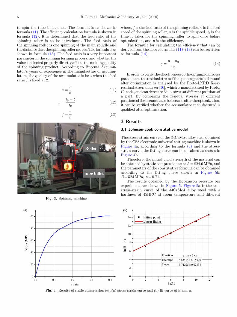
The stress-strain curve of the 34CrMo4 alloy steel obtainedby the CSS electronic universal testing machine is shown inFigure 4a, according to the formula (3) and the stress-strain curve, the fitting curve can be obtained as shown inFigure 4b.
Therefore, the initial yield strength of the material canbe obtained by static compression test:A=824.6MPa, andthe parameters of the constitutive formula can be obtainedaccording to the fitting curve shown in Figure 5b:B=524MPa, n=0.71.
The results obtained by the Hopkinson pressure barexperiment are shown in Figure 5. Figure 5a is the truestress-strain curve of the 34CrMo4 alloy steel with ahardness of 45HRC at room temperature and different
ress-strain curve and (b) fit curve of B and n.
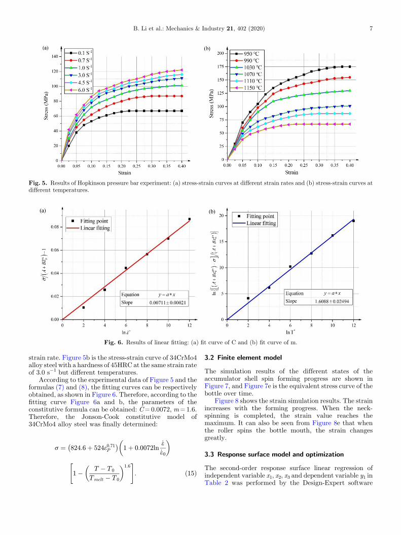
Fig. 5. Results of Hopkinson pressure bar experiment: (a) stress-strain curves at different strain rates and (b) stress-strain curves atdifferent temperatures.
Fig. 6. Results of linear fitting: (a) fit curve of C and (b) fit curve of m.
B. Li et al.: Mechanics & Industry 21, 402 (2020) 7
strain rate. Figure 5b is the stress-strain curve of 34CrMo4alloy steel with a hardness of 45HRC at the same strain rateof 3.0 s�1 but different temperatures.
According to the experimental data of Figure 5 and theformulas (7) and (8), the fitting curves can be respectivelyobtained, as shown in Figure 6. Therefore, according to thefitting curve Figure 6a and b, the parameters of theconstitutive formula can be obtained: C=0.0072, m=1.6.Therefore, the Jonson-Cook constitutive model of34CrMo4 alloy steel was finally determined:
s ¼ 824:6þ 524e0:71P
� �1þ 0:0072ln
_e_e0
� �
1� T � T 0
Tmelt � T 0
� �1:6" #
: ð15Þ
3.2 Finite element model
The simulation results of the different states of theaccumulator shell spin forming progress are shown inFigure 7, and Figure 7e is the equivalent stress curve of thebottle over time.
Figure 8 shows the strain simulation results. The strainincreases with the forming progress. When the neck-spinning is completed, the strain value reaches themaximum. It can also be seen from Figure 8e that whenthe roller spins the bottle mouth, the strain changesgreatly.
3.3 Response surface model and optimization
The second-order response surface linear regression ofindependent variable x1, x2, x3 and dependent variable y1 inTable 2 was performed by the Design-Expert software
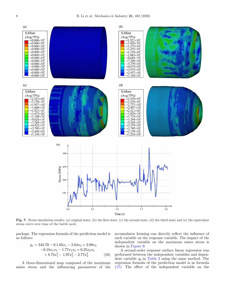
Fig. 7. Stress simulation results: (a) original state, (b) the first state, (c) the second state, (d) the third state and (e) the equivalentstress curve over time of the bottle neck.
8 B. Li et al.: Mechanics & Industry 21, 402 (2020)
package. The regression formula of the prediction model isas follows:
y1 ¼ 343:70� 0:1:65x1 � 2:64x2 þ 2:09x3
�0:18x1x2 � 1:77x1x3 þ 0:25x2x3
þ 8:75x21 � 1:97x2
2 � 2:77x23 ð16Þ
A three-dimensional map composed of the maximummises stress and the influencing parameters of the
accumulator forming can directly reflect the influence ofeach variable on the response variable. The impact of theindependent variable on the maximum mises stress isshown in Figure 9.
A second-order response surface linear regression wasperformed between the independent variables and depen-dent variable y2 in Table 2 using the same method. Theregression formula of the prediction model is as formula(17). The effect of the independent variable on the
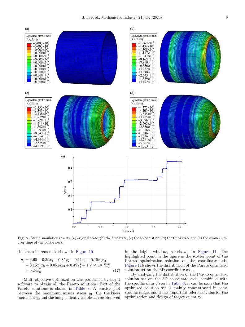
Fig. 8. Strain simulation results: (a) original state, (b) the first state, (c) the second state, (d) the third state and (e) the strain curveover time of the bottle neck.
B. Li et al.: Mechanics & Industry 21, 402 (2020) 9
thickness increment is shown in Figure 10.
y2 ¼ 4:65� 0:39x1 þ 0:85x2 � 0:11x3 � 0:15x1x2
� 0:15x1x3 þ 0:05x2x3 þ 0:49x21 þ 1:7 � 10�2x2
2
þ 0:24x23 ð17Þ
Multi-objective optimization was performed by Isightsoftware to obtain all the Pareto solutions. Part of thePareto solutions is shown in Table 3. A scatter plotbetween the maximum misses stress y1, the thicknessincrement y2 and the independent variable can be observed
in the Isight window, as shown in Figure 11. Thehighlighted point in the figure is the scatter point of thePareto optimization solution on the coordinate axis.Figure 11b shows the distribution of the Pareto optimizedsolution set on the 3D coordinate axis.
By analyzing the distribution of the Pareto optimizedsolution set on the 3D coordinate axis, combined withthe specific data given in Table 3, it can be seen that theoptimized solution set is mainly concentrated in somespecific range, and it has important reference value for theoptimization and design of target quantity.
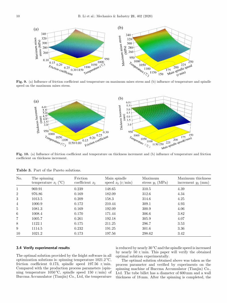
Fig. 9. (a) Influence of friction coefficient and temperature on maximum mises stress and (b) influence of temperature and spindlespeed on the maximum mises stress.
Fig. 10. (a) Influence of friction coefficient and temperature on thickness increment and (b) influence of temperature and frictioncoefficient on thickness increment.
Table 3. Part of the Pareto solutions.
No. The spinningtemperature x1 (°C)
Frictioncoefficient x2
Main spindlespeed x3 (r/min)
Maximumstress y1 (MPa)
Maximum thicknessincrement y2 (mm)
1 969.91 0.239 148.65 310.5 4.392 976.86 0.169 182.09 312.6 4.343 1013.5 0.209 158.3 314.6 4.254 1000.9 0.172 210.44 309.1 4.935 1081.3 0.169 192.09 300.9 4.066 1008.4 0.170 171.44 306.6 3.827 1005.7 0.261 192.18 305.9 4.078 1122.1 0.175 211.25 296.7 3.539 1114.5 0.232 191.25 301.6 3.3610 1021.2 0.173 197.56 298.62 3.42
10 B. Li et al.: Mechanics & Industry 21, 402 (2020)
3.4 Verify experimental results
The optimal solution provided by the Isight software in alloptimization solutions is: spinning temperature 1021.2 °C,friction coefficient 0.173, spindle speed 197.56 r/min.Compared with the production process parameters (spin-ning temperature 1050 °C, spindle speed 150 r/min) ofBuccma Accumulator (Tianjin) Co., Ltd, the temperature
is reduced by nearly 30 °C and the spindle speed is increasedby nearly 50 r/min. This paper will verify the obtainedoptimal solution experimentally.
The optimal solution obtained above was taken as theprocess parameter and verified by experiments on thespinning machine of Buccma Accumulator (Tianjin) Co.,Ltd. The tube billet has a diameter of 600mm and a wallthickness of 18mm. After the spinning is completed, the
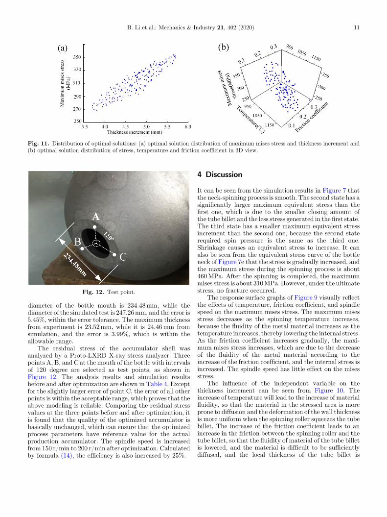
Fig. 11. Distribution of optimal solutions: (a) optimal solution distribution of maximum mises stress and thickness increment and(b) optimal solution distribution of stress, temperature and friction coefficient in 3D view.
Fig. 12. Test point.
B. Li et al.: Mechanics & Industry 21, 402 (2020) 11
diameter of the bottle mouth is 234.48mm, while thediameter of the simulated test is 247.26mm, and the error is5.45%, within the error tolerance. The maximum thicknessfrom experiment is 23.52mm, while it is 24.46mm fromsimulation, and the error is 3.99%, which is within theallowable range.
The residual stress of the accumulator shell wasanalyzed by a Proto-LXRD X-ray stress analyzer. Threepoints A, B, and C at the mouth of the bottle with intervalsof 120 degree are selected as test points, as shown inFigure 12. The analysis results and simulation resultsbefore and after optimization are shown in Table 4. Exceptfor the slightly larger error of point C, the error of all otherpoints is within the acceptable range, which proves that theabove modeling is reliable. Comparing the residual stressvalues at the three points before and after optimization, itis found that the quality of the optimized accumulator isbasically unchanged, which can ensure that the optimizedprocess parameters have reference value for the actualproduction accumulator. The spindle speed is increasedfrom 150 r/min to 200 r/min after optimization. Calculatedby formula (14), the efficiency is also increased by 25%.
4 Discussion
It can be seen from the simulation results in Figure 7 thatthe neck-spinning process is smooth. The second state has asignificantly larger maximum equivalent stress than thefirst one, which is due to the smaller closing amount ofthe tube billet and the less stress generated in the first state.The third state has a smaller maximum equivalent stressincrement than the second one, because the second staterequired spin pressure is the same as the third one.Shrinkage causes an equivalent stress to increase. It canalso be seen from the equivalent stress curve of the bottleneck of Figure 7e that the stress is gradually increased, andthe maximum stress during the spinning process is about460MPa. After the spinning is completed, the maximummises stress is about 310MPa. However, under the ultimatestress, no fracture occurred.
The response surface graphs of Figure 9 visually reflectthe effects of temperature, friction coefficient, and spindlespeed on the maximum mises stress. The maximum misesstress decreases as the spinning temperature increases,because the fluidity of the metal material increases as thetemperature increases, thereby lowering the internal stress.As the friction coefficient increases gradually, the maxi-mum mises stress increases, which are due to the decreaseof the fluidity of the metal material according to theincrease of the friction coefficient, and the internal stress isincreased. The spindle speed has little effect on the misesstress.
The influence of the independent variable on thethickness increment can be seen from Figure 10. Theincrease of temperature will lead to the increase of materialfluidity, so that the material in the stressed area is moreprone to diffusion and the deformation of the wall thicknessis more uniform when the spinning roller squeezes the tubebillet. The increase of the friction coefficient leads to anincrease in the friction between the spinning roller and thetube billet, so that the fluidity of material of the tube billetis lowered, and the material is difficult to be sufficientlydiffused, and the local thickness of the tube billet is
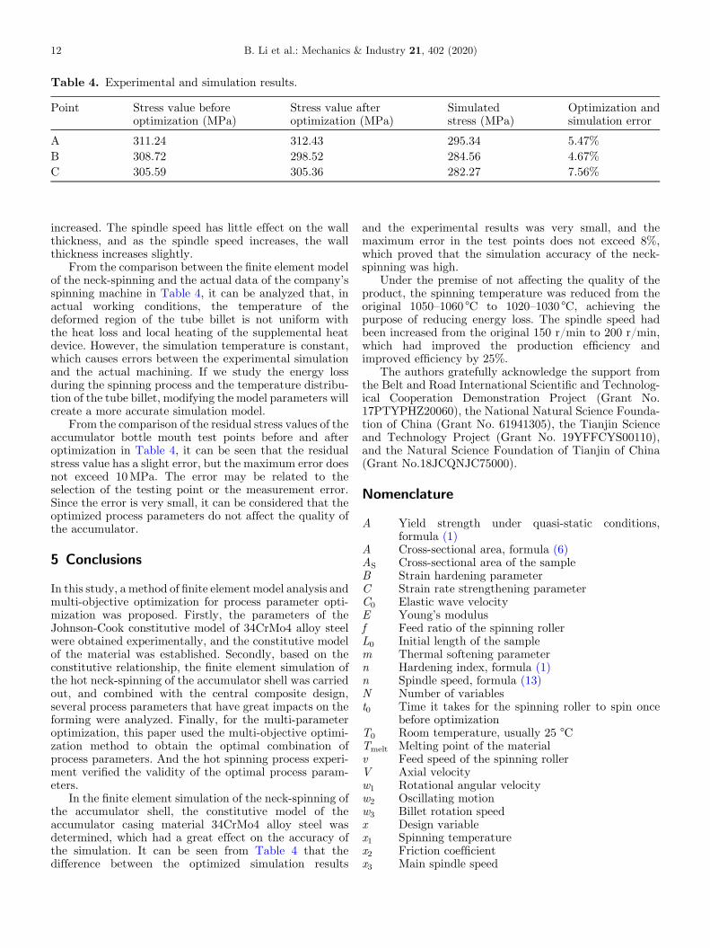
Table 4. Experimental and simulation results.
Point Stress value beforeoptimization (MPa)
Stress value afteroptimization (MPa)
Simulatedstress (MPa)
Optimization andsimulation error
A 311.24 312.43 295.34 5.47%B 308.72 298.52 284.56 4.67%C 305.59 305.36 282.27 7.56%
12 B. Li et al.: Mechanics & Industry 21, 402 (2020)
increased. The spindle speed has little effect on the wallthickness, and as the spindle speed increases, the wallthickness increases slightly.
From the comparison between the finite element modelof the neck-spinning and the actual data of the company’sspinning machine in Table 4, it can be analyzed that, inactual working conditions, the temperature of thedeformed region of the tube billet is not uniform withthe heat loss and local heating of the supplemental heatdevice. However, the simulation temperature is constant,which causes errors between the experimental simulationand the actual machining. If we study the energy lossduring the spinning process and the temperature distribu-tion of the tube billet, modifying the model parameters willcreate a more accurate simulation model.
From the comparison of the residual stress values of theaccumulator bottle mouth test points before and afteroptimization in Table 4, it can be seen that the residualstress value has a slight error, but the maximum error doesnot exceed 10MPa. The error may be related to theselection of the testing point or the measurement error.Since the error is very small, it can be considered that theoptimized process parameters do not affect the quality ofthe accumulator.
5 Conclusions
In this study, a method of finite element model analysis andmulti-objective optimization for process parameter opti-mization was proposed. Firstly, the parameters of theJohnson-Cook constitutive model of 34CrMo4 alloy steelwere obtained experimentally, and the constitutive modelof the material was established. Secondly, based on theconstitutive relationship, the finite element simulation ofthe hot neck-spinning of the accumulator shell was carriedout, and combined with the central composite design,several process parameters that have great impacts on theforming were analyzed. Finally, for the multi-parameteroptimization, this paper used the multi-objective optimi-zation method to obtain the optimal combination ofprocess parameters. And the hot spinning process experi-ment verified the validity of the optimal process param-eters.
In the finite element simulation of the neck-spinning ofthe accumulator shell, the constitutive model of theaccumulator casing material 34CrMo4 alloy steel wasdetermined, which had a great effect on the accuracy ofthe simulation. It can be seen from Table 4 that thedifference between the optimized simulation results
and the experimental results was very small, and themaximum error in the test points does not exceed 8%,which proved that the simulation accuracy of the neck-spinning was high.
Under the premise of not affecting the quality of theproduct, the spinning temperature was reduced from theoriginal 1050–1060 °C to 1020–1030 °C, achieving thepurpose of reducing energy loss. The spindle speed hadbeen increased from the original 150 r/min to 200 r/min,which had improved the production efficiency andimproved efficiency by 25%.
The authors gratefully acknowledge the support fromthe Belt and Road International Scientific and Technolog-ical Cooperation Demonstration Project (Grant No.17PTYPHZ20060), the National Natural Science Founda-tion of China (Grant No. 61941305), the Tianjin Scienceand Technology Project (Grant No. 19YFFCYS00110),and the Natural Science Foundation of Tianjin of China(Grant No.18JCQNJC75000).
Nomenclature
A
Yield strength under quasi-static conditions,formula (1)A
Cross-sectional area, formula (6) AS Cross-sectional area of the sample B Strain hardening parameter C Strain rate strengthening parameter C0 Elastic wave velocity E Young’s modulus f Feed ratio of the spinning roller L0 Initial length of the sample m Thermal softening parameter n Hardening index, formula (1) n Spindle speed, formula (13) N Number of variables t0 Time it takes for the spinning roller to spin oncebefore optimization
T0 Room temperature, usually 25 °C Tmelt Melting point of the material v Feed speed of the spinning roller V Axial velocity w1 Rotational angular velocity w2 Oscillating motion w3 Billet rotation speed x Design variable x1 Spinning temperature x2 Friction coefficient x3 Main spindle speed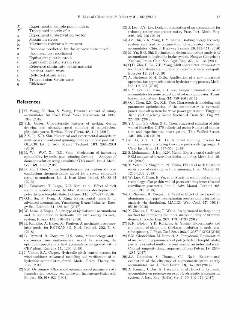
B. Li et al.: Mechanics & Industry 21, 402 (2020) 13
X
Experimental sample point matrix XT Transposed matrix of x y Experimental observation vector y1 Maximum stress y2 Maximum thickness increment _y Response predicted by the approximate model a Undetermined coefficient eP Equivalent plastic strain _e Equivalent plastic strain rate _e0 Reference strain rate of the material ei Incident strain wave er Reflected strain wave ee Transmission Strain wave h EfficiencyReferences
[1] C. Wang, Y. Han, S. Wang, Pressure control of rotaryaccumulator, Int. Conf. Fluid Power Mechatron. 14, 1395–1398 (2015)
[2] V.E. Geller, Characteristic features of necking duringdrawing and ultrahigh-speed spinning of polyethylenephthalate yarns, Review, Fibre Chem. 48, 1–11 (2016)
[3] Z.X. Li, X.D. Shu, Numerical and experimental analysis onmulti-pass conventional spinning of the cylindrical part withGH3030, Int. J. Adv. Manuf. Technol. 103, 2893–2901(2019)
[4] H. Wu, W.C. Xu, D.B. Shan, Mechanism of increasingspinnability by multi-pass spinning forming � Analysis ofdamage evolution using a modified GTNmodel, Int. J. Mech.Sci. 159, 1–19 (2019)
[5] B. Sun, J. Guo, Y. Lei, Simulation and verification of a non-equilibrium thermodynamic model for a steam catapult’ssteam accumulator, Int. J. Heat Mass Transf. 85, 88–97(2015)
[6] R. Tomisawa, T. Ikaga, K.H. Kim, et al., Effect of meltspinning conditions on the fiber structure development ofpolyethylene terephthalate, Polymer 116, 367–377 (2016)
[7] Q.H. Su, F. Peng, J. Xing, Experimental research onadvanced accumulator, Yuanzineng Kexue Jishu/At. Ener-gy Sci. Technol. 51, 636–640 (2017)
[8] W. Latas, J. Stojek, A new type of hydrokinetic accumulatorand its simulation in hydraulic lift with energy recoverysystem, Energy 153, 836–848 (2018)
[9] H. Kadakia, A. Baker, M. Paulsen, A mechanistic accumu-lator model for RETRAN-3D, Nucl. Technol. 202, 71–80(2018)
[10] B. Ryszard, B. Zbigniew, H.S. Anna, Methodology and acontinuous time mathematical model for selecting theoptimum capacity of a heat accumulator integrated with aCHP plant, Energies 11, 1240 (2018)
[11] I. Victor, S.A. Casper, Hydraulic pitch control system forwind turbines: Advanced modeling and verification of anhydraulic accumulator, Simul. Model. Pract. Theory. 79,1–22 (2017)
[12] S.M. Ostroumov, Choice and optimization of parameters of atranspiration cooling accumulator, Inzhenerno-FizicheskiiZhurnal 60, 918–922 (1991)
[13] J. Lee, U.Y. Lee, Design optimization of an accumulator forreducing rotary compressor noise, Proc. Inst. Mech. Eng.226, 285–296 (2012)
[14] J.Z. Hui, Y.K. Yang, H.Y. Zhang, Braking energy recoverysystem and control optimization of excavator based onaccumulator, Chin. J. Highway Transp. 29, 143–151 (2016)
[15] M. Yu, B.Q. Shi, Optimization design and robust analysis ofaccumulator in hydraulic brake system, Nongye GongchengXuebao/Trans. Chin. Soc. Agri. Eng. 27, 132–136 (2011)
[16] Q.D. Zhu, P. Lu, Z.B. Yang, Multi-parameter optimizationfor the wet steam accumulator of a steam-powered catapult,Energies 12, 234 (2019)
[17] A. Hashemi, M.H. Gollo, Application of a new integratedoptimization approach in sheet hydroforming process, Mech.Ind. 19, 303 (2018)
[18] U.Y. Lee, B.J. Kim, J.B. Lee, Design optimization of anaccumulator for noise reduction of rotary compressor, Trans.Korean Soc. Mech. Eng. 35, 759–766 (2011)
[19] Q.J. Chen, Z.X. Xu, X.H. Yue, Characteristic modeling andparameter optimization of the accumulator in hydraulicpower take-off system for wave power generation, YingyongJichu yu Gongcheng Kexue Xuebao/J. Basic Sci. Eng. 27,226–237 (2019)
[20] Y.C. Lin, S.S. Qian, X.M. Chen, Staggered spinning of thin-walled Hastelloy C-276 cylindrical parts: Numerical simula-tion and experimental investigation, Thin-Walled Struct.140, 466–476 (2019)
[21] M. Li, Y.Y. Xu, H. Li, A novel spinning process forsimultaneously producing two cone parts with big angle, J.Chin. Inst. Eng. 41, 547–556 (2018)
[22] S. Mohammad, J. Iraj, K.N. Mehdi, Experimental study andFEM analysis of forward hot dieless spinning, Mech. Ind. 19,404 (2018)
[23] T. Yoichi, K. Shigefumi, N. Takuo, Effects of neck length onoccurrence of cracking in tube spinning, Proc. Manuf. 15,1200–1206 (2018)
[24] W. Luo, F. Chan, B. Vu, et al. Study on compound spinningtechnology of large thin-walled parts with ring inner ribs andcurvilinear generatrix, Int. J. Adv. Manuf. Technol. 98,1199–1216 (2018)
[25] X. Zhiyong, R. Yuejuan, L. Wenbo, Effect of feed speed onaluminum alloy pipe neck-spinning process and deformationanalysis via simulation, MATEC Web Conf. 67, 05011–05016 (2016)
[26] X. Zhanga, L. Zhaoa, T. Wena, An optimized neck-spinningmethod for improving the inner surface quality of titaniumdomes, Procedia Eng. 207, 1731–1736 (2017)
[27] K.R. Biplov, Y.P. Korkolis, A. Yoshio, Experiments andsimulation of shape and thickness evolution in multi-passtube spinning, J. Phys. Conf. Ser. 1063, 012087–012092 (2018)
[28] S.M. Ghoreishian, M. Norouzi, A. Fereydooni, Optimizationof melt-spinning parameters of poly(ethylene terephthalate)partially oriented multi-filament yarn in an industrial scale:Central composite design approach, Fibers Polym. 18, 1280–1287 (2017)
[29] J.J. Cummins, S. Thomas, C.J. Nash, Experimentalevaluation of the efficiency of a pneumatic strain energyaccumulator, Int. J. Fluid Power. 18, 167–180 (2017)
[30] A. Kumar, J. Das, K. Dasgupta, et al., Effect of hydraulicaccumulator on pressure surge of a hydrostatic transmissionsystem, J. Inst. Eng. (India) Ser. C 99, 169–174 (2017)
14 B. Li et al.: Mechanics & Industry 21, 402 (2020)
[31] J. Cai, K. Wang, P. Zhai, A modified Johnson-Cookconstitutive formula to predict hot deformation behaviorof Ti-6Al-4V alloy, J. Mater. Eng. Perf. 24, 32–44 (2015)
[32] L.Z. Zhou, L.M. Yang, Comparative study on constitutivemodels to predict flow stress of Fe-Cr-Ni preform reinforcedAl-Si-Cu-Ni-Mg composite, J.Wuhan Univ. Technol. Mater.Sci. Ed. 32, 666–676 (2017)
[33] M. Alitavoli, A. Darvizeh, M. Moghaddam, Numericalmodeling based on coupled Eulerian-Lagrangian approachand experimental investigation of water jet spot weldingprocess, Thin-Walled Struct. 127, 617–628 (2018)
[34] X.-q. Chang, L.-y. Zhang, Y.-b. Yang, J.-l. Ren, ConstitutiveModels for Compressive Deformation of AZ80 MagnesiumAlloy underMultiple LoadingDirections and Strain Rates, J.Iron Steel Res. Int. 23, 64–68 (2016)
[35] D.-N. Zhang, Q.-Q. Shangguan, C.-J. Xie, F. Liu, Amodified Johnson-Cook model of dynamic tensile behaviorsfor 7075-T6 aluminum alloy, J. Alloys Compd. 619, 186–194 (2015)
[36] M. Machorro-López José, A. Bellino, S. Marchesiello,Wavelets-based damage localization on beams under theinfluence of moving loads, Mechanics 14, 107–113 (2013)
[37] K. Erik, Meshing recommendations for the P-approachapplication in ABAQUS � A tool for pheno-numericalspring-in prediction, Compos. Struct. 203, 1–10 (2018)
[38] S.Q. Zhang, J.X. Yan, L. Cao, Crack Propagation Simulationof Hot Mill Grinding with Wood Based on ADAMS andABAQUS, Linye Kexue/Scientia Silvae Sinicae. 54, 149–156(2018)
[39] Z.R. Yang, X.L. Bai, Y.H. Xie, Finite element analysis on thecollision between serial risers by using ABAQUS software, J.Vib. Shock 36, 196–200 (2017)
[40] X. Shi, P. Teixeira, J. Zhang, Kriging response surfacereliability analysis of a ship-stiffened plate with initialimperfections, Struct. Infrastruct. Eng. 89, 1–16 (2014)
[41] X.L. Jia, J. Wang, Y.L. Zhang, True stress and shakedownanalysis of pressure vessel under repeated internal pressure,Mech. Ind. 17, 410 (2016)
[42] C.N.C. Bhatra, S.A. Saheb, Note on reduction of dimension-ality for second order response surface design model,Commun. Stat. Theory Methods 46, 3520–3525 (2016)
[43] R.K. Kamaraj, J.G. Thankachi Raghuvaran, A.F. Pan-imayam, Performance and exhaust emission optimization ofa dual fuel engine by response surface methodology, Energies11, 3508 (2018)
[44] W.S. Liu, X.M. Yao, C.Q. Li, Optimization of configurationparameters of tail-sitter UAV based on response surface andgenetic algorithm, Trans. Chin. Soc. Agri. Mach. 50, 88–95(2019)
[45] A. Caglar, T. Sahan,M.S. Cogenli, A novel central compositedesign based response surface methodology optimizationstudy for the synthesis of Pd/CNT direct formic acid fuel cellanode catalyst, Int. J. Hydrogen Energy 43, 11002–11011(2018)
[46] C. Lu, L. Gao, X. Li, Energy-efficient multi-pass turningoperation using multi-objective backtracking search algo-rithm, J. Clean. Prod. 137, 1516–1531 (2016)
[47] M.A. Sahali, I. Belaidi, R. Serra, New approach for robustmulti-objective optimization of turning parameters usingprobabilistic genetic algorithm, Int. J. Adv. Manuf. Technol.83, 1265–1279 (2016)
[48] J. Song, J. Li, Q.H. Yang, Multi-objective optimizationand its application on irrigation scheduling based onAquaCrop and NSGA-II, J. Hydraulic Eng. 49, 1284–1295(2018)
[49] J. Huang, Z.B. Chen, Q.M. Liu,Multi-objective optimizationfor laser closure process parameters in vitro skin tissue basedon NSGA-II, Chin. J. Lasers 46, 0207001 (2019)
[50] L.B. Huo, Z.Q. Cao, F. Zhang, Numerical and experimentalstudy on TC4-DT titanium alloy structure after double coldexpansion, J. Northwest. Polytech. Univ. 36, 701–708 (2018)
Cite this article as: B. Li, Y. Li, P. Zhu,W.Ma, Y. Xiao, X. Li, Study on optimization of thermal spinning process of accumulatorshell, Mechanics & Industry 21, 402 (2020)