Embed Size (px)
Citation preview

35
Journal of Environmental Friendly Materials, Vol. 5, No. 1, 2021, 35-46.
Metallurgical Aspects of the Spinning Process in Metallic Liners
S. M. J. Hoseini1, H. Ghayour1, A. S. Golazani1,2*, M. K. Asgarani1, I. Ebrahimzadeh1
1Advanced Materials Research Center, Department of Materials Engineering, Najafabad Branch, Islamic Azad
University, Najafabad, Iran. 2Department of Materials Engineering, Karaj Branch, Islamic Azad University, Karaj, Iran.
Received: 01 February 2021 - Accepted: 06 April 2021
Abstract
Spinning is one of the novel and unique processes in metal forming for the production of cylindrical and conical thin-walled
parts with precise tolerances, good surface smoothness and suitable mechanical properties. This process includes
conventional spinning, shear forming and flow forming. Metallurgical investigation is great importance in this process. The
microstructure obtained from the spinning specimens, especially the shear forming and flow-forming, shows that the grains
and the impurity particles are elongated in the direction of the main axis and are also stretched in the circumferential
direction. This change in grain size on the roller side was larger than on the mandrel side. Fragmentation of coarse and brittle
particles has also been observed. Also, due to the amount of strain and forces applied, the grain size decreases and as a
result, the strength increases. The texture of the spinning parts has also changed. As the thickness decreases, the orientation
of the grains and textures increases and the large angle boundaries increase.
Keywords: Spinning, Shear Forming, Flow Forming, Microstructure, Texture.
1. Introduction
Spinning is a method of forming metals that has the
ability to produce seamless and hollow volumes
with a axis of symmetry such as cones, cylinders,
tubes, hemispheres or a combination of them. Also
in this process, hollow elliptical parts can be
produced with special methods. Whereas the deep
drawing process cannot be used to produce a part
with complex size or structure and the high cost of
the tools and mold, spinning is a suitable alternative
method. This process is widely used to produce
parts needed in the oil and gas industry, automotive,
pressure vessels, kitchen appliances, etc. For proper
use of these accessories, the final properties of the
manufactured part are important. Fig. 1. shows a
schematic of the spinning process and the equipment
and components of the device [1]. Since the high
cost of tools and molds is always an important point
in pressing or deep drawing, spinning is an
economical and efficient process with many
capabilities and an alternative and acceptable
method for production of parts.
Fig. 1. Schematic of the spinning process [1]
*Corresponding author
Email address: [email protected]
The advantages of the spinning process are [1, 2, 3]:
- Production without chips, seamless and cold
- Improving the mechanical properties of the
material such as yield strength
- Ability to produce parts with different dimensions
- No need for some operations such as machining,
grinding, etc.
- It is economical compared to other methods
- Dimensional accuracy of manufactured parts.
The spinning process is divided into two categories
in terms of thickness change during shaping: (i) in
conventional spinning, the wall‐thickness of the
blank remains nearly constant throughout the
process, thus the final wall‐thickness of the spun
part is equal to the thickness of the blank and this
process can be done with manual and machine
equipment. (ii) in shear spinning and flow forming
the wall‐thickness of the blank is reduced in power
spinning or flow forming and can only be done with
special equipment [4]. Fig. 2. shows the
classification types of spinning process.
Fig. 2. Classification of spinning processes [5].
1.1. Conventional Spinning
In this method, the deformation is done with a
bending mechanism and wall-thickness does not
change significantly. This process can be done by
using manual or machine devices. In this process, a
plate is placed between a rotating mandrel and the
36
Journal of Environmental Friendly Materials, Vol. 5, No. 1, 2021, 35-46.
roller of the machine. A compressive force is
applied which gradually bends the metal on the
mandrel after several working steps [6].
1.2. Shear Spinning
Another type of spinning is shear forming or shear
spinning, which is a subset of machine spinning.
The reason for this naming is the application of pure
shear force that is applied to the workpiece and
reduces the thickness and thinning of its wall [6].
In shear spinning, the roller in each pass reduces the
workpiece wall-thickness in a predictable and
calculable way, while the blank diameter remains
constant during the process.
The final thickness of the workpiece in conical shear
spinning follows Eq. (1)., which is called the sine
law, as shown in Fig. 3. [6, 7].
𝑡𝑓 = 𝑡0 𝑠𝑖𝑛 (𝛼
2) Eq. (1).
𝑟 = 1 − 𝑠𝑖𝑛 (𝛼
2) Eq. (2).
Fig. 3. Sine law [8].
Where tf is the final thickness of the workpiece, t0 is
the initial thickness of the preform and (α / 2) is the
half-angle of the mandrel cone. However, the result
is in real condition usually slightly different from
what is obtained from the sine law [8].Reduction of
the thickness more or less than in Eq. (2). causes the
flange to wrinkle or tear. The shear strain γ is
obtained from Eq. (3). [9]:
𝛾 = 𝑐𝑜𝑡 (𝛼
2) Eq. (3).
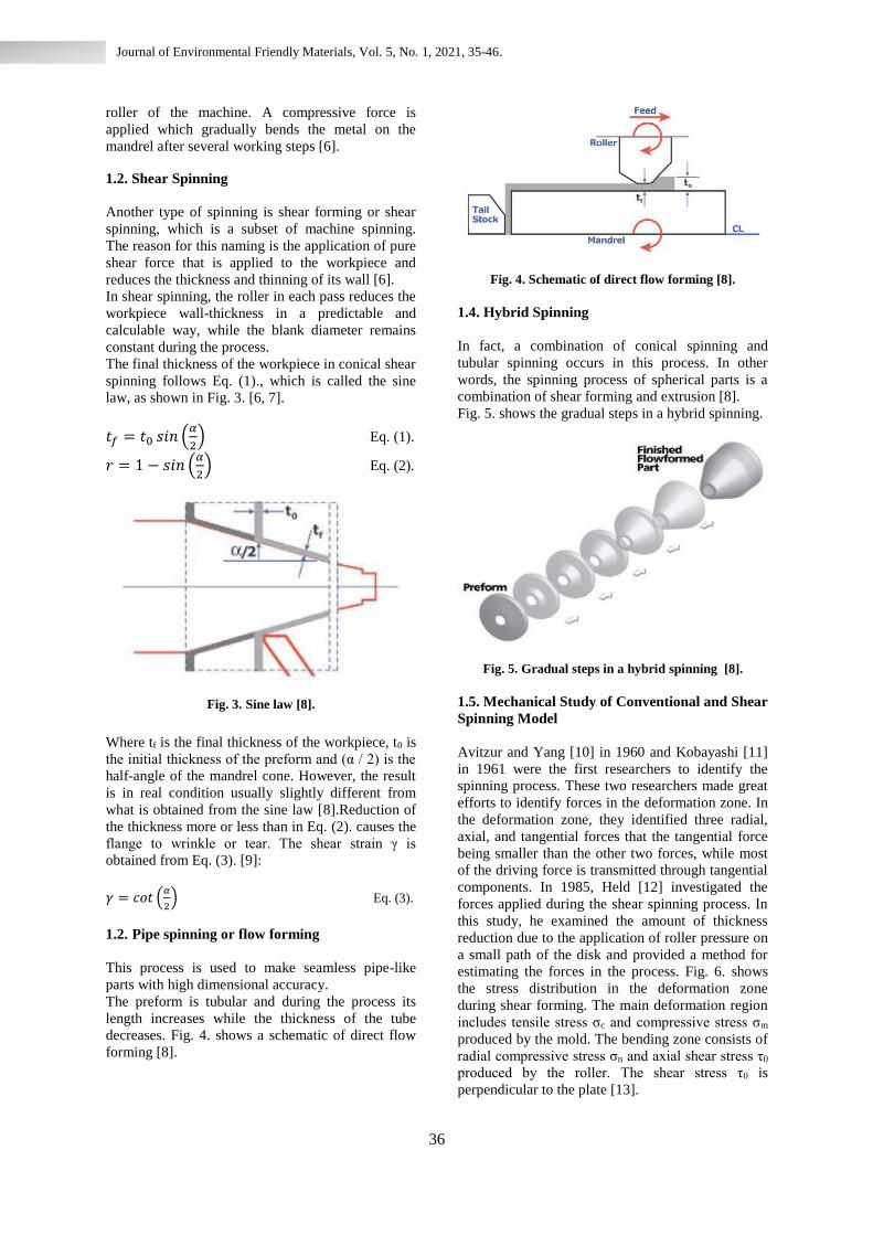
1.2. Pipe spinning or flow forming
This process is used to make seamless pipe-like
parts with high dimensional accuracy.
The preform is tubular and during the process its
length increases while the thickness of the tube
decreases. Fig. 4. shows a schematic of direct flow
forming [8].
Fig. 4. Schematic of direct flow forming [8].
1.4. Hybrid Spinning
In fact, a combination of conical spinning and
tubular spinning occurs in this process. In other
words, the spinning process of spherical parts is a
combination of shear forming and extrusion [8].
Fig. 5. shows the gradual steps in a hybrid spinning.
Fig. 5. Gradual steps in a hybrid spinning [8].
1.5. Mechanical Study of Conventional and Shear
Spinning Model
Avitzur and Yang [10] in 1960 and Kobayashi [11]
in 1961 were the first researchers to identify the
spinning process. These two researchers made great
efforts to identify forces in the deformation zone. In
the deformation zone, they identified three radial,
axial, and tangential forces that the tangential force
being smaller than the other two forces, while most
of the driving force is transmitted through tangential
components. In 1985, Held [12] investigated the
forces applied during the shear spinning process. In
this study, he examined the amount of thickness
reduction due to the application of roller pressure on
a small path of the disk and provided a method for
estimating the forces in the process. Fig. 6. shows
the stress distribution in the deformation zone
during shear forming. The main deformation region
includes tensile stress σc and compressive stress σm
produced by the mold. The bending zone consists of
radial compressive stress σn and axial shear stress τ0
produced by the roller. The shear stress τ0 is
perpendicular to the plate [13].

37
Journal of Environmental Friendly Materials, Vol. 5, No. 1, 2021, 35-46.
Fig. 6. Schematic of stress state in deformation area
during shear spinning [13].
In the conventional spinning model, it is assumed
that the thickness will not change during the
forming process (as shown in Fig. 7.). To produce
the final workpiece with radius R, the initial sheet
with radius r is needed. Considering the constant
volume and assuming that the thickness is constant
for the production of the final part, we follow
according to Eq. (4) [14]:
𝜋𝑟2𝑡 =2
3𝜋[(𝑅 + 𝑡)3 − 𝑅3] Eq. (4).
Fig. 7. Theory model of (a) Conventional spinning
(constant thickness), (b) Shear forming
(constant diameter) [14].
If r* is the radius of the initial sheet required to
produce the final workpiece with radius Rn and
angle α shown in Fig. 7., with the constant volume
theory Eq. (5). is obtained by[14]:
πr∗2t =2
3π[((R + t)3 − R3)(1 + cos α)] Eq. (5).
Where according to Eq. (6). is obtained:
cos α =√R2−Rn2
R Eq. (6).
Thus we can be expressed r * as a function of Rn
according to Eq. (7):
r∗(Rn) = √(2R2 + 2Rt2 +2
3t2)
R−√R2−n2
R Eq. (7).
Due to the fact that in the conventional spinning
model there is no change in thickness, so the amount
of strain in the direction of thickness will be zero.
The engineering hoop strain will easily be obtained
as Eq. (8) with consider to the initial (2πr*) and final
(2πRn) circumference [14]:
εh (Rn) =2πRn−2πr∗
2πr∗ =Rn−r∗
r∗ Eq. (8).
The engineering radial strain εr is determined using
constant volume law in terms of the engineering
strains as follows
(1 + εr)(1 + εh)(1 + εt) = 1 Eq. (9).
εr =−εh
1+εh Eq. (10).
εr(Rn) =r∗−Rn
Rn Eq. (11).
In shear spinning model, it is assumed that the
diameter of the sheet will not change during the
forming process and in fact the thickness in this
model will be variable [14]. In this model, the radial
position for each element does not change during
the process.
Thus the circumference of each circular element
(2πRn) remains constant during the process,
resulting in zero hoop strain. If t is the initial
thickness and α is the angle shown for point A in
Fig. 7.b, it can be seen that the final thickness will
be equal to t cosα. As a result, engineering strain in
the direction of thickness is obtained by Eq. (12)
[14]:
𝜀𝑡 (α ) = 𝑡 𝑐𝑜𝑠𝛼−𝑡
𝑡 = 𝑐𝑜𝑠𝛼 − 1 Eq. (12).
Therefore, the radial strain is obtained according to
the law of constant volume as follows.
ε t (α ) = 1
cos 𝛼 -1 Eq. (13).
𝜀𝑡 (Rn) = √𝑅2−𝑅𝑛2
𝑅 − 1 Eq. (14).
𝜀𝑡 (Rn) =𝑅
√𝑅2−𝑅𝑛2 -1 Eq. (15).
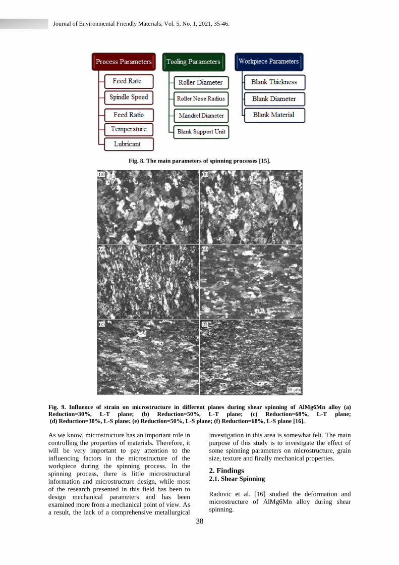
1.6. Main spinning parameters
There are three main types of parameters in spinning
processes, which are shown in Fig. 8. [15].
38
Journal of Environmental Friendly Materials, Vol. 5, No. 1, 2021, 35-46.
Fig. 8. The main parameters of spinning processes [15].
Fig. 9. Influence of strain on microstructure in different planes during shear spinning of AlMg6Mn alloy (a)
Reduction=30%, L-T plane; (b) Reduction=50%, L-T plane; (c) Reduction=68%, L-T plane;
(d) Reduction=30%, L-S plane; (e) Reduction=50%, L-S plane; (f) Reduction=68%, L-S plane [16].
As we know, microstructure has an important role in
controlling the properties of materials. Therefore, it
will be very important to pay attention to the
influencing factors in the microstructure of the
workpiece during the spinning process. In the
spinning process, there is little microstructural
information and microstructure design, while most
of the research presented in this field has been to
design mechanical parameters and has been
examined more from a mechanical point of view. As
a result, the lack of a comprehensive metallurgical
investigation in this area is somewhat felt. The main
purpose of this study is to investigate the effect of
some spinning parameters on microstructure, grain
size, texture and finally mechanical properties.
2. Findings 2.1. Shear Spinning
Radovic et al. [16] studied the deformation and
microstructure of AlMg6Mn alloy during shear
spinning.
39
Journal of Environmental Friendly Materials, Vol. 5, No. 1, 2021, 35-46.
They reduced the thicknesses 30%, 50% and 68%
by using different mandrels. The grain structure is
gradually developed refining during shear spinning. The grains are elongated in the axial direction by
increasing the amount of thickness reduction and are
also stretched in the rotational direction. In this
study, the most optimal combination of strength and
elongation was obtained, which has been attributed
to grain refinement and reaction of dislocations with
Mg and Mn particles and atoms in solid solution.
Finally, the effect of initial grain size as well as
mechanical properties have been investigated. In
this study, they concluded that high accumulated
energy, as a result of local deformation and high
strain rate, may lead to dynamic recovery. Recovery
in Al-Mg alloys usually stops during other
deformation modes. On the other hand, using
transmission electron microscopy (TEM), it has
been proven that dynamic recovery occurs during
shear spinning of AlMg3 alloy in high reducing
thickness, but this does not occur in cold rolling in
the same thickness reduction [16].
They also observed that during shear spinning, grain
refinement occurs gradually in both small and large
grains as the thickness decreases. The grains are
elongated in the axial direction (Fig. 9.a to Fig. 9.c)
and also stretched in the direction of rotation (Fig.
9.d to Fig. 9.f). Fragmentation of coarse and brittle
particles is also observed. They also reported an
important result, they reported that the grain size in
the shear spinning specimens did not differ much
from the rolled specimens in the same conditions.
They reported that shear spinning was effective in
improving the strength of AlMg6Mn alloy while
maintaining the elongation approximately.
Hardness and tensile strength gradually increase as
the wall thickness reductions. This phenomenon is
explained by grain refinement, hardening by particle
and Mg and Mn effects. Strength and hardness
indicate dependence on grain size, which increases
with decreasing grain size. High values of
elongation are justified by the dynamic recovery that
occurs with high accumulation energy as a result of
local deformation and high strain rate [16].
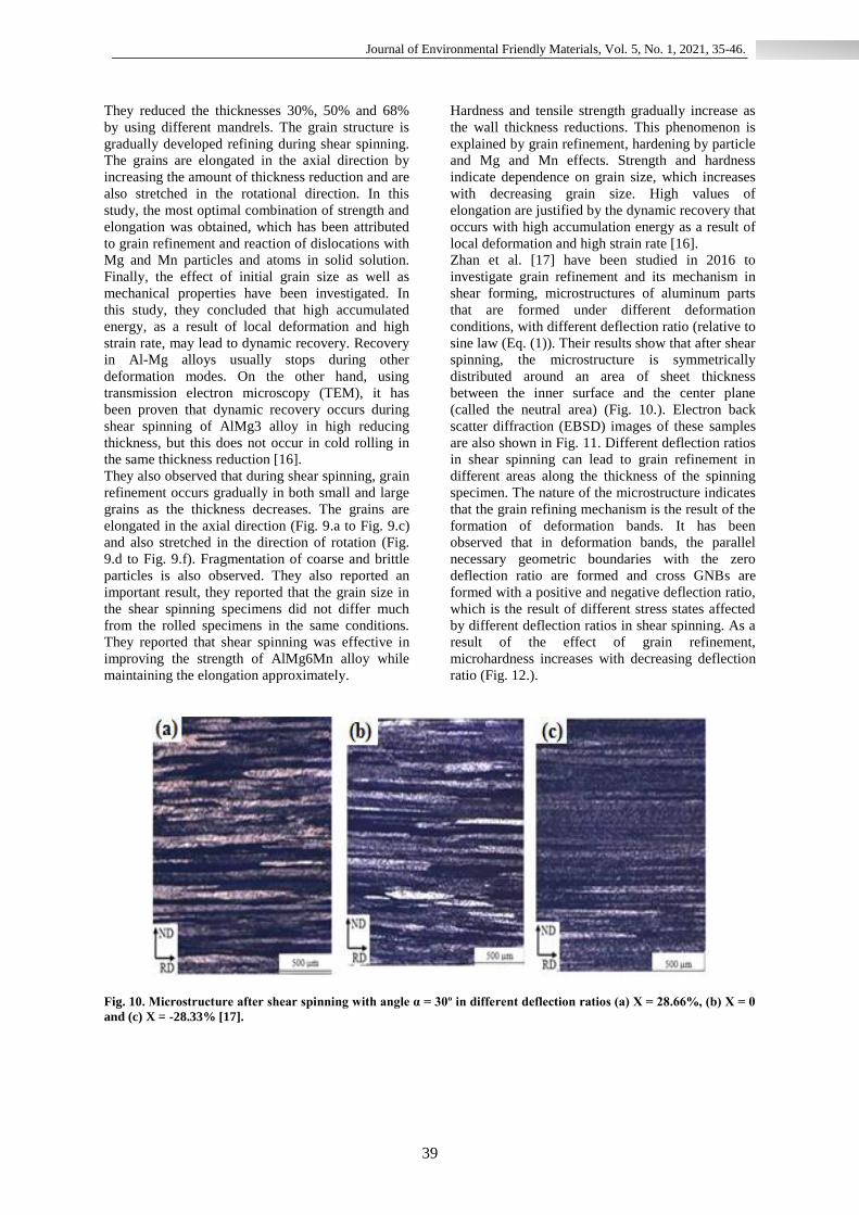
Zhan et al. [17] have been studied in 2016 to
investigate grain refinement and its mechanism in
shear forming, microstructures of aluminum parts
that are formed under different deformation
conditions, with different deflection ratio (relative to
sine law (Eq. (1)). Their results show that after shear
spinning, the microstructure is symmetrically
distributed around an area of sheet thickness
between the inner surface and the center plane
(called the neutral area) (Fig. 10.). Electron back
scatter diffraction (EBSD) images of these samples
are also shown in Fig. 11. Different deflection ratios
in shear spinning can lead to grain refinement in
different areas along the thickness of the spinning
specimen. The nature of the microstructure indicates
that the grain refining mechanism is the result of the
formation of deformation bands. It has been
observed that in deformation bands, the parallel
necessary geometric boundaries with the zero
deflection ratio are formed and cross GNBs are
formed with a positive and negative deflection ratio,
which is the result of different stress states affected
by different deflection ratios in shear spinning. As a
result of the effect of grain refinement,
microhardness increases with decreasing deflection
ratio (Fig. 12.).
Fig. 10. Microstructure after shear spinning with angle α = 30º in different deflection ratios (a) X = 28.66%, (b) X = 0
and (c) X = -28.33% [17].
40
Journal of Environmental Friendly Materials, Vol. 5, No. 1, 2021, 35-46.
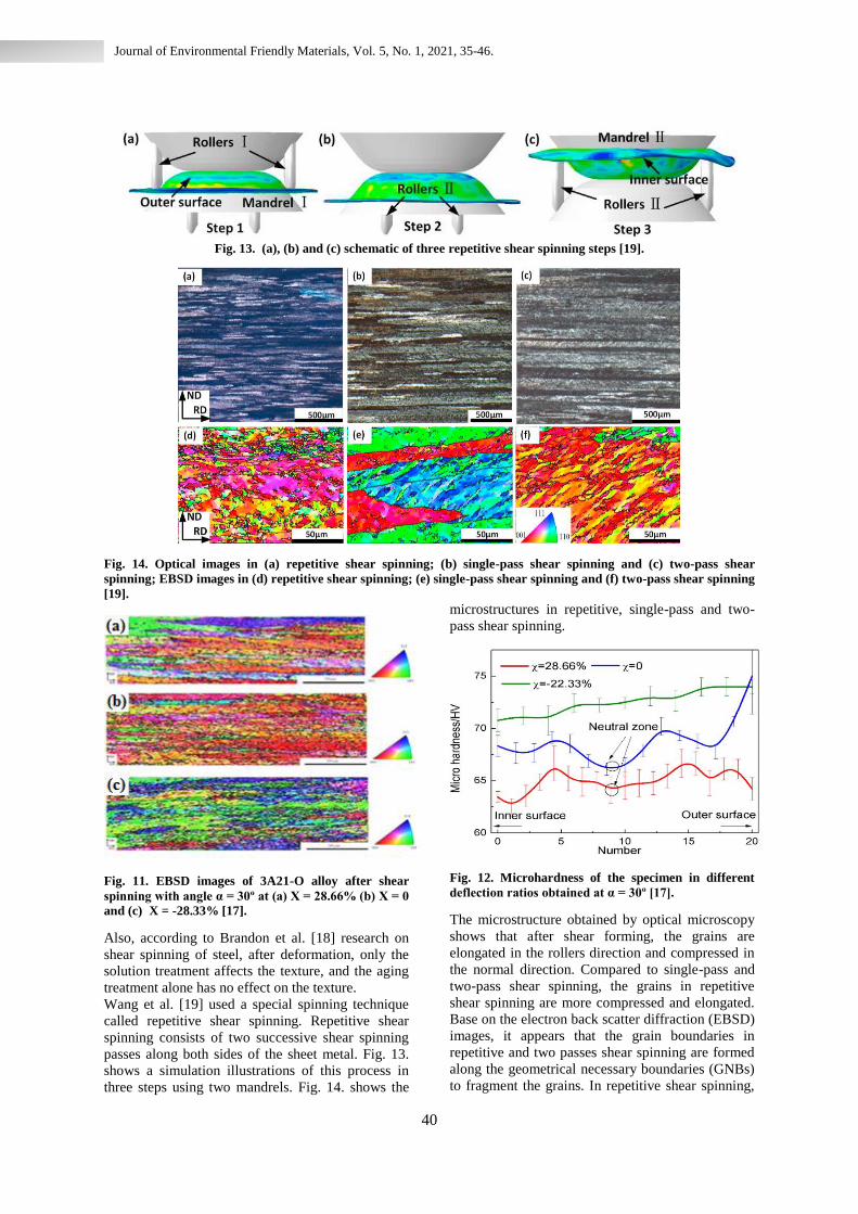
Fig. 13. (a), (b) and (c) schematic of three repetitive shear spinning steps [19].
Fig. 14. Optical images in (a) repetitive shear spinning; (b) single-pass shear spinning and (c) two-pass shear
spinning; EBSD images in (d) repetitive shear spinning; (e) single-pass shear spinning and (f) two-pass shear spinning
[19].
Fig. 11. EBSD images of 3A21-O alloy after shear
spinning with angle α = 30º at (a) X = 28.66% (b) X = 0
and (c) X = -28.33% [17].
Also, according to Brandon et al. [18] research on
shear spinning of steel, after deformation, only the
solution treatment affects the texture, and the aging
treatment alone has no effect on the texture.
Wang et al. [19] used a special spinning technique
called repetitive shear spinning. Repetitive shear
spinning consists of two successive shear spinning
passes along both sides of the sheet metal. Fig. 13.
shows a simulation illustrations of this process in
three steps using two mandrels. Fig. 14. shows the
microstructures in repetitive, single-pass and two-
pass shear spinning.
Fig. 12. Microhardness of the specimen in different
deflection ratios obtained at α = 30º [17].
The microstructure obtained by optical microscopy
shows that after shear forming, the grains are
elongated in the rollers direction and compressed in
the normal direction. Compared to single-pass and
two-pass shear spinning, the grains in repetitive
shear spinning are more compressed and elongated.
Base on the electron back scatter diffraction (EBSD)
images, it appears that the grain boundaries in
repetitive and two passes shear spinning are formed
along the geometrical necessary boundaries (GNBs)
to fragment the grains. In repetitive shear spinning,
41
Journal of Environmental Friendly Materials, Vol. 5, No. 1, 2021, 35-46.
a large number of small subdivided grains are
formed as shown in Fig. 14.d The grain size
obtained from the repetitive shear spinning process
is smaller than the one-pass and two-pass process
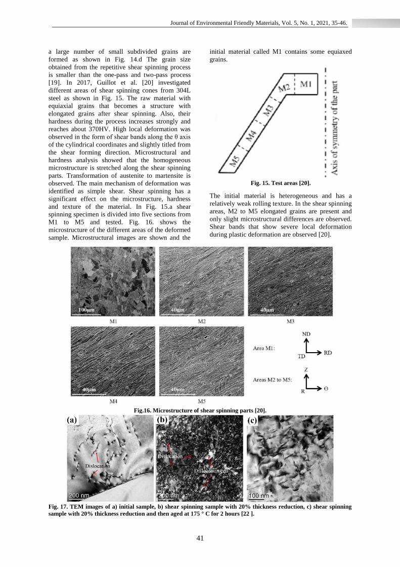
[19]. In 2017, Guillot et al. [20] investigated
different areas of shear spinning cones from 304L
steel as shown in Fig. 15. The raw material with
equiaxial grains that becomes a structure with
elongated grains after shear spinning. Also, their
hardness during the process increases strongly and
reaches about 370HV. High local deformation was
observed in the form of shear bands along the θ axis
of the cylindrical coordinates and slightly titled from
the shear forming direction. Microstructural and
hardness analysis showed that the homogeneous
microstructure is stretched along the shear spinning
parts. Transformation of austenite to martensite is
observed. The main mechanism of deformation was
identified as simple shear. Shear spinning has a
significant effect on the microstructure, hardness
and texture of the material. In Fig. 15.a shear
spinning specimen is divided into five sections from
M1 to M5 and tested. Fig. 16. shows the
microstructure of the different areas of the deformed
sample. Microstructural images are shown and the
initial material called M1 contains some equiaxed
grains.
Fig. 15. Test areas [20].
The initial material is heterogeneous and has a
relatively weak rolling texture. In the shear spinning
areas, M2 to M5 elongated grains are present and
only slight microstructural differences are observed.
Shear bands that show severe local deformation
during plastic deformation are observed [20].
Fig.16. Microstructure of shear spinning parts [20].
Fig. 17. TEM images of a) initial sample, b) shear spinning sample with 20% thickness reduction, c) shear spinning
sample with 20% thickness reduction and then aged at 175 ° C for 2 hours [22 ].
42
Journal of Environmental Friendly Materials, Vol. 5, No. 1, 2021, 35-46.
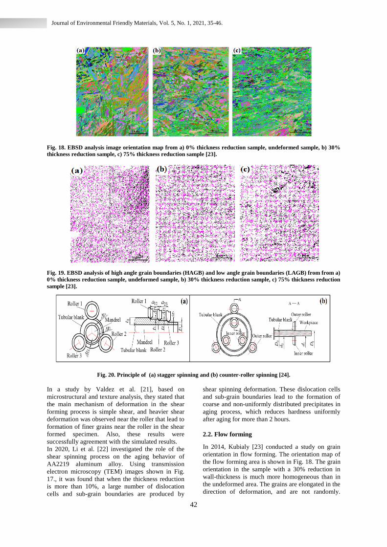
Fig. 18. EBSD analysis image orientation map from a) 0% thickness reduction sample, undeformed sample, b) 30%
thickness reduction sample, c) 75% thickness reduction sample [23].
Fig. 19. EBSD analysis of high angle grain boundaries (HAGB) and low angle grain boundaries (LAGB) from from a)
0% thickness reduction sample, undeformed sample, b) 30% thickness reduction sample, c) 75% thickness reduction
sample [23].
Fig. 20. Principle of (a) stagger spinning and (b) counter-roller spinning [24].
In a study by Valdez et al. [21], based on
microstructural and texture analysis, they stated that
the main mechanism of deformation in the shear
forming process is simple shear, and heavier shear
deformation was observed near the roller that lead to
formation of finer grains near the roller in the shear
formed specimen. Also, these results were
successfully agreement with the simulated results.
In 2020, Li et al. [22] investigated the role of the
shear spinning process on the aging behavior of
AA2219 aluminum alloy. Using transmission
electron microscopy (TEM) images shown in Fig.
17., it was found that when the thickness reduction
is more than 10%, a large number of dislocation
cells and sub-grain boundaries are produced by
shear spinning deformation. These dislocation cells
and sub-grain boundaries lead to the formation of
coarse and non-uniformly distributed precipitates in
aging process, which reduces hardness uniformly
after aging for more than 2 hours.
2.2. Flow forming
In 2014, Kubialy [23] conducted a study on grain
orientation in flow forming. The orientation map of
the flow forming area is shown in Fig. 18. The grain
orientation in the sample with a 30% reduction in
wall-thickness is much more homogeneous than in
the undeformed area. The grains are elongated in the
direction of deformation, and are not randomly.
43
Journal of Environmental Friendly Materials, Vol. 5, No. 1, 2021, 35-46.
Flow forming causes the grains to elongate in the x
direction, which results the number of grains
decreases in this direction. Fig. 19. shows the high
angle and low angle grain boundaries. The ratio
(HAGB / LAGB) is equal to
(42.56 / 57.44), which indicates a large number of
sub-grain boundaries. This indicates that even
before the flow forming process, there are sub-
boundaries in the microstructure. Kubialy by using
EBSD analysis showed that with increasing the
amount of strain (reduction of wall-thickness) the
orientation of the grains will be much more and
more homogeneous and the high angle boundaries
will increase somewhat [23].
Xiao et al. [24] investigated the effect of flow
forming process on grain refinement and observed
the overall grain refinement in the direction of the
thickness of the cylinder produced by the spinning
method. In this study, they demonstrated the
material flow model based on the upper bound
method and compared stagger spinning with
counter-roller spinning shown in Fig. 20. They also
performed metallographic and microstructural
analysis, which was very consistent with theoretical
analysis.
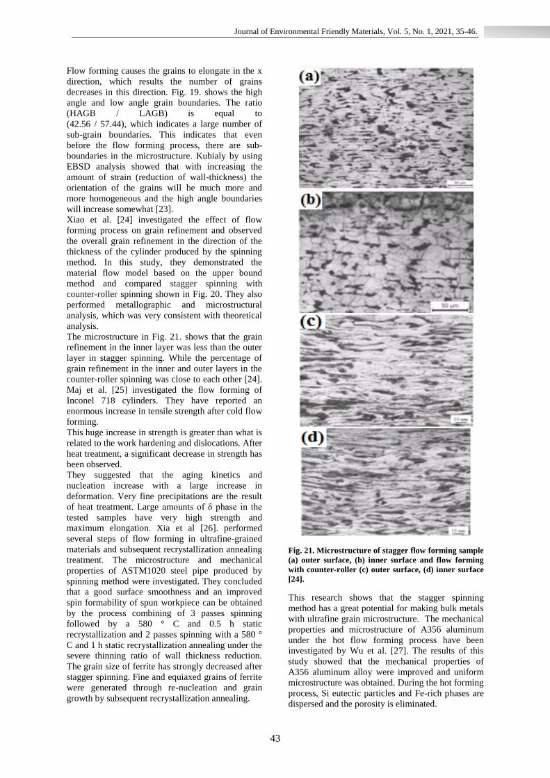
The microstructure in Fig. 21. shows that the grain
refinement in the inner layer was less than the outer
layer in stagger spinning. While the percentage of
grain refinement in the inner and outer layers in the
counter-roller spinning was close to each other [24].
Maj et al. [25] investigated the flow forming of
Inconel 718 cylinders. They have reported an
enormous increase in tensile strength after cold flow
forming.
This huge increase in strength is greater than what is
related to the work hardening and dislocations. After
heat treatment, a significant decrease in strength has
been observed.
They suggested that the aging kinetics and
nucleation increase with a large increase in
deformation. Very fine precipitations are the result
of heat treatment. Large amounts of δ phase in the
tested samples have very high strength and
maximum elongation. Xia et al [26]. performed
several steps of flow forming in ultrafine-grained
materials and subsequent recrystallization annealing
treatment. The microstructure and mechanical
properties of ASTM1020 steel pipe produced by
spinning method were investigated. They concluded
that a good surface smoothness and an improved
spin formability of spun workpiece can be obtained
by the process combining of 3 passes spinning
followed by a 580 ° C and 0.5 h static
recrystallization and 2 passes spinning with a 580 °
C and 1 h static recrystallization annealing under the
severe thinning ratio of wall thickness reduction.
The grain size of ferrite has strongly decreased after
stagger spinning. Fine and equiaxed grains of ferrite
were generated through re-nucleation and grain
growth by subsequent recrystallization annealing.
Fig. 21. Microstructure of stagger flow forming sample
(a) outer surface, (b) inner surface and flow forming
with counter-roller (c) outer surface, (d) inner surface
[24].
This research shows that the stagger spinning
method has a great potential for making bulk metals
with ultrafine grain microstructure. The mechanical
properties and microstructure of A356 aluminum
under the hot flow forming process have been
investigated by Wu et al. [27]. The results of this
study showed that the mechanical properties of
A356 aluminum alloy were improved and uniform
microstructure was obtained. During the hot forming
process, Si eutectic particles and Fe-rich phases are
dispersed and the porosity is eliminated.

44
Journal of Environmental Friendly Materials, Vol. 5, No. 1, 2021, 35-46.
Fig. 22. a) Schematic of the spinning process 3S, b) and c) EBSD images of surface microstructure in samples with
two different feed amounts [29].
Recrystallization of Al matrix and AlSiTi phase
precipitation also occur. The results of mechanical
properties tests also show that an improvement in
the final strength, an increase in toughness and a
decrease in the microhardness of the deformed
sample compared to the cast alloy were observed.
These results are attributed to the uniform
distribution of fine spherical eutectic Si particles,
increase in dislocation density, the elimination of
casting defects, and the fine-grained recrystallization
grain structure. The microstructure and mechanical
properties of hot flow forming and subsequent
annealing TA15 alloy pipes were also investigated
by Xu et al. [28]. The results of this study showed
that with increasing the number of flow forming
passes, the fiber microstructure is gradually
elongated in the axial direction and the circular
microstructure is stretched in the direction of
rotation. Also, the tensile stress increases and the
elongation decreases not only in the axial direction
but also in the circumferential direction. When the
thickness reduction ratio increases to close to or
over 40%, the tensile strength increases rapidly and
the elongation decreases, which means that titanium
alloy can be strengthened bi-directionally by power
spinning. The ductility of the spun TA15 alloy can
be improved by annealing treatment at a temperature
not higher than the recrystallization temperature and
slightly reducing the tensile strength. Debin et al.
[29] tested and investigated the cold flow forming
process in Ti-15-3 alloy. They suggested a method
that, using reverse extrusion and solution heat
treatment, could improve the microstructure of the
original billet and prevent cracking during spinning.
After the first spinning pass and the solution heat
treatment, the crystals of the material are refined and
the thickness reduction range increases in
subsequent spinning passes. In this way, by
increasing the number of spinning passes, the billet
is more easily shaped. As the number of spinning
passes and the degree of deformation increase, the
crystals become more refined.
The maximum allowable thickness reduction rate
has increased for each passes and the smallest
allowable value for the thickness reduction rate has
decreased, which has increased the thickness
reduction rate range. As the number of spinning
passes increases, spinning will become increasingly
easier. Solution Heat treatment is necessary in cold
spinning of Ti-15-3 alloy, so that the residual
stresses from the deformation are eliminated and the
crystals are refined. This treatment will help
improve the plasticity of the billet. A new method
for surface strengthening was introduced by Ren et
al. [30] called surface strengthening by spinning
(3S) method, which causes a difference in surface
layer microstructure compared to the sub-layers of
Cu-11% Al alloy (Fig. 22.).
Depending on the amount of grain refinement, the
microstructural difference can be divided into four
areas, which include the nanoscale grain area, the
fine grain area, the fine grain area, and the coarse
grain area from the surface to the center.
Meanwhile, the abundance of grain boundaries and
twin boundaries has been effective in inhibiting the
movement of dislocations in the surface layer during
the plastic deformation process. Subsequently, this
method has improved the surface mechanical
properties due to differences in the surface
microstructure compared to the sub-layers.
2.3. Conventional Spinning
In 2020, Gondo et al. [31] conducted research on the
conventional spinning in several passes on AA1050
aluminum sheet. By examining the microstructure
and texture of the spun workpiece, they showed that
the crystalline orientation had changed in two-thirds
of the thickness of the workpiece, and included four
types of crystalline texture, shown schematically in
Fig. 23.
45
Journal of Environmental Friendly Materials, Vol. 5, No. 1, 2021, 35-46.
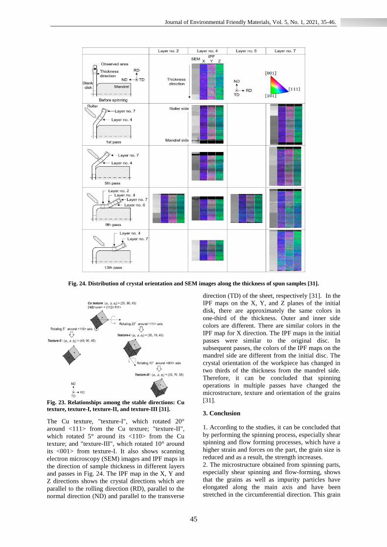
Fig. 24. Distribution of crystal orientation and SEM images along the thickness of spun samples [31].
Fig. 23. Relationships among the stable directions: Cu
texture, texture-I, texture-II, and texture-III [31].
The Cu texture, "texture-I", which rotated 20°
around <111> from the Cu texture; "texture-II",
which rotated 5° around its <110> from the Cu
texture; and "texture-III", which rotated 10° around
its <001> from texture-I. It also shows scanning
electron microscopy (SEM) images and IPF maps in
the direction of sample thickness in different layers
and passes in Fig. 24. The IPF map in the X, Y and
Z directions shows the crystal directions which are
parallel to the rolling direction (RD), parallel to the
normal direction (ND) and parallel to the transverse
direction (TD) of the sheet, respectively [31]. In the
IPF maps on the X, Y, and Z planes of the initial
disk, there are approximately the same colors in
one-third of the thickness. Outer and inner side
colors are different. There are similar colors in the
IPF map for X direction. The IPF maps in the initial
passes were similar to the original disc. In
subsequent passes, the colors of the IPF maps on the
mandrel side are different from the initial disc. The
crystal orientation of the workpiece has changed in
two thirds of the thickness from the mandrel side.
Therefore, it can be concluded that spinning
operations in multiple passes have changed the
microstructure, texture and orientation of the grains
[31].
3. Conclusion
1. According to the studies, it can be concluded that
by performing the spinning process, especially shear
spinning and flow forming processes, which have a
higher strain and forces on the part, the grain size is
reduced and as a result, the strength increases.
2. The microstructure obtained from spinning parts,
especially shear spinning and flow-forming, shows
that the grains as well as impurity particles have
elongated along the main axis and have been
stretched in the circumferential direction. This grain
46
Journal of Environmental Friendly Materials, Vol. 5, No. 1, 2021, 35-46.
size change was greater on the roller side than on the
mandrel side. Fragmentation of coarse and brittle
particles is also observed. The nature of the
microstructure indicates that the grain refining
mechanism is the result of the formation of
deformation bands.
3. With the changes in the microstructure, the
texture of the spinning parts has also changed. With
increasing thickness reduction, the orientation of the
grains and texture changes and the high angle
boundaries increase.
4. The microstructure of different areas of a cone
produced by shear spinning method, from apex to
base, has been investigated to show that there is no
difference in the microstructure of these areas.
5. The results obtained from hot spinning show that
the mechanical properties have been improved and a
uniform microstructure is obtained. During the hot
forming process, eutectic particles and impurity
phases are dispersed and the porosity is eliminated.
As the number of passes increases, the fiber
microstructure gradually elongated in the axial
direction and the circular microstructure stretched in
the circumferential direction.
References
[1] P. Pawar, A. Pagar, A. Shah and S. Yevale, Int.
J. Recent Innov. Trends Comput. Commun.,
5(2017), 1280.
[2] S. Kalpakjian and S. Rajagopal, Appl.
Metalworking, 2(1982), 211 .
[3] D. Marini, D. Cunningham, P. Xirouchakis and
J. Corney, Int. J. Mech. Eng. Technol. (IJMET),
7(2016), 285 .
[4] C. C. Wong, T. Dean and J. Lin, International J.
Mach. Tools Manuf., 43(2003), 1419 .
[5] Q. Xia, G. Xiao, H. Long, X. Cheng and X.
Sheng, Int. J. of Mach. Tools Manuf., 85(2014),
100.
[6] E. Hagan and J. Jeswiet, Proc. Inst. Mech. Eng.,
Part B: J. Eng. Manuf., 217(2003), 213 .
[7] W. F. Hosford and R. M. Caddell: Metal
Forming Mechanics And Metallurgy, Third Edition,
Cambridge University Press, (2007) .
[8] M. Sivanandini, S. Dhami and B. Pabla, Int. J.
Sci. Eng. Res., 3(2012), 1 .
[9] M. Hayama, T. Murota and H. Kudo, Bulletin Of
JSME, 8(1965),453 .
[10] B. Avitzur and C. T. Yang, Journal of Eng.
Ind., Trans. of the ASME, 82(1960), 231 .
[11] S. Kobayashi, I. K. Hall and E. G. Thomsen, J.
of Eng. Ind., Trans. of the ASME, 83(1961), 485 .
[12] M. Held, Propellants, Explosives, Pyrotechnics,
10(1985), 125 .
[13] F. Wang, P. Su, L. Qin, S. Dong, Y. Li and j.
Dong, Acta Metallurg. Sin., 33(2020), 1226 .
[14] H. Beni, Y. Beni and F. Biglari, Part C: J.
Mech. Eng. Sci., 225(2010), 509 .
[15] M.Tapase, M. han and K.V.Gurav, Int. J. Eng.
Dev..Res., 12(2014), 3004 .
[16] L. Radović, M. Nikačević and B. Jordović,
Trans. Nonferrous Metals Soc. China, 22(2012),
991 .
[17] M. Zhan, X. Wang and H. Long, Mater. Des.,
108(2016), 207 .
[18] D. Brandon, P. Ari gur, Z. Bratt and M. Gur,
Mater. Sci. Eng., 44(1980), 185 .
[19] X.X.Wang, M.Zhan and M.W.Fu, Procedia.
Eng., 207(2017), 1725 .
[20] M. Guillot, T. McCormack, M. Tuffs, A.
Rosochowsk, S.Halliday and P. Blackwell,
Procedia. Eng., 207(2017), 1719 .
[21] K. Valdez, B. Wynne and M. Lee, Proceedings
Of The 22nd International Esaform Conference On
Mater. Forming: Esaform 2019(AIP), 2113(2019),
170001 .
[22] Z. Li, M. Zhan, X. Fan, X. Wang and F. Ma, J.
Mater. Res. Technol., 9(2020), 4706 .
[23] C. Kubilay, Writer, Flow Forming Of
Aeroengine Materials. [Performance], PHD Thesis,
University of Manchester,En., (2014).
[24] G. Xiao, Q. Xia, X. Cheng and Y. Zhou, The
Int. J. Adv. Manuf. Technol., 78(2015), 971 .
[25] P.Maj, P.Blyskun, S.Kut, B.Romelczyk-
Baishya, T.Morgala, B.Adamczyk-Cieslak and
J.Mizera, J. Mater. Proces. Tech., 253(2018), 64 .
[26] Q. Xia, G. Xiao, H. Long, X. Cheng and B.
Yang, Mater. Des., 59(2014), 516 .
[27] X. Y. Wu, H. R. Zhang, H. L. Chen, L. N. Jia
and H. Zhang, China Foundry, 14, (2017),138 .
[28] W. C. Xu, D. B. Shan, Z. L. Wang, G. P. Yang,
Y. LÜ and D. C. Kang, Trans. Nonferrous Metals
Soc. of China, 17, (2007), 1205 .
[29] S.Debin, L.Yan, L.Ping and X. Yi, J. Mater.
Proces. Technol., 115(2001), 380 .
[30] C. X. Ren, Q. Wang, Z. J. Zhang, Y. K. Zhu
and Z. F. Zhang, Acta. Metallurg. Sin. (En. Lett.),
30, (2017), 212 .
[31] S. Gondo, H. Arai, S. Kajino and S. Nakano,
Metals, 10, (2020), 793.