Embed Size (px)
Citation preview
TALAT 1501
TALAT Lecture 1501
Aluminium: Physical Properties, Characteristics and Alloys
60 pages, 44 figures
Basic Level
prepared by Ron Cobden, Alcan, Banbury
Objectives:
− to provide a survey of the aluminium alloys available to the user − to describe their various properties − to give an insight into the choice of aluminium for a proposed application.
In the context of this lecture not every individual alloy and its properties have been treated in detail, but rather divided into alloy types with reference to the most commonly used alloys. For further details on alloy properties the reader is referred to available databanks like ALUSELECT of the European Aluminium Association (EAA) or to the European and national materials standards. Prerequisites: - good engineering background in materials, design and manufacturing processes Date of Issue: 1994 EAA - European Aluminium Association

TALAT 1501 2
1501 Aluminium: Physical Properties, Characteristics and Alloys
Contents 1501 Aluminium: Physical Properties, Characteristics and Alloys .........2
1501.01 History and Present State of Aluminium Production.............................. 4 The History and Production Process of Aluminium ................................................4 The Aluminium Industry Today...............................................................................7 Recycled or Secondary Aluminium .........................................................................8
1501.02 Important Physical Properties................................................................... 8 Atomic Structure......................................................................................................8 Crystal Structure ......................................................................................................9 Density .....................................................................................................................9 Electrical Conductivity and Resistivity..................................................................10 Non-Magnetic Property..........................................................................................11 Thermal Conductivity ............................................................................................12 Reflectance and Emissivity....................................................................................13 Corrosion Resistance .............................................................................................15 Thermal Expansion ................................................................................................17 Melting Temperature .............................................................................................18 Specific and Latent Heats ......................................................................................19
1501.03 Aluminium Alloy Availability.................................................................. 19 The Four Digit System for Wrought Alloy Identification......................................20 Alloy Systems ........................................................................................................22
Unalloyed Aluminium ....................................................................................... 24 Aluminium - Copper Alloys............................................................................... 25 Aluminium - Manganese Alloys ........................................................................ 25 Aluminium - Silicon Alloys ............................................................................... 25 Aluminium - Magnesium Alloys ........................................................................ 26 Aluminium - Magnesium - Silicon Alloys.......................................................... 26 Aluminium-Zinc-Magnesium and Aluminium-Zinc-Magnesium-Copper Alloys26 Aluminium - plus other elements which do not fall into any of the patterns outlined above................................................................................................... 27
The Five Digit System for Cast Alloy Identification .............................................27 Unalloyed Aluminium ....................................................................................... 27 Aluminium Alloys, Ingots and Casting ............................................................. 27

TALAT 1501 3
1501.04 Basic Physical Metallurgy ........................................................................ 29 Work Hardening.....................................................................................................29 Dispersion Hardening ............................................................................................30 Solid Solution Hardening.......................................................................................30 Precipitation Hardening .........................................................................................31 Temper Designations Non Heat-Treatable Alloys.................................................32 Temper Designations Heat-Treatable Alloys.........................................................33 Common Alloys and Applications.........................................................................34
1501.05 Aluminium Alloys ; Mechanical Properties............................................ 36 Tensile Strength .....................................................................................................36 Strength/Weight Ratio ...........................................................................................36 Proof Stress ............................................................................................................37 Elastic Properties ...................................................................................................39 Elongation ..............................................................................................................40 Compression ..........................................................................................................41 Bearing...................................................................................................................42 Shear ......................................................................................................................43 Hardness.................................................................................................................43 Ductility .................................................................................................................44 Creep ......................................................................................................................45 Properties at Elevated Temperatures......................................................................46 Properties at Low Temperatures ............................................................................48 Impact Strength ......................................................................................................49 Fracture Characteristics..........................................................................................49 Fatigue....................................................................................................................52
1501.06 Literature/References ............................................................................... 58 1501.07 List of Figures............................................................................................ 59

TALAT 1501 4
1501.01 History and Present State of Aluminium Production
• The history and production process of aluminium • The aluminium industry today • Recycled or secondary aluminium
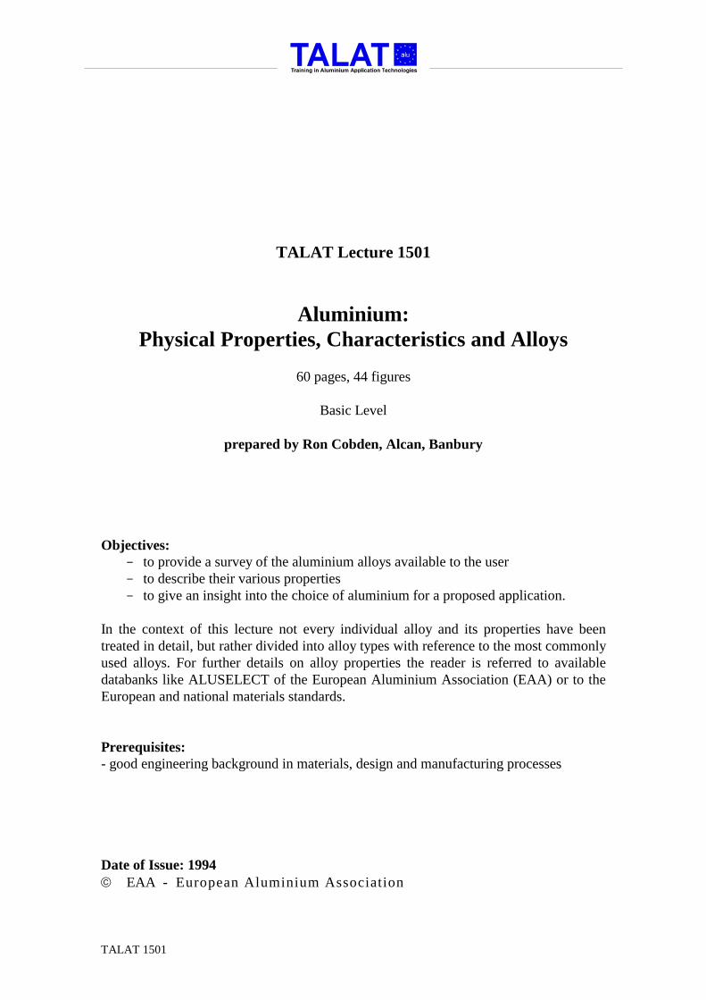
The History and Production Process of Aluminium Rare and expensive a century ago, aluminium has since been identified as the most common metal on earth, forming about eight percent of the earth's crust. It is the third most plentiful element known to man. Only oxygen and silicon (sand) exist in greater quantities. It was only in 1808 that Sir Humphrey Davy, the British electrochemist, established the existence of aluminium, and it was not until 17 years later that the Danish scientist Oersted produced the first tiny pellet of the metal. The next step in the ″discovery″ of aluminium was the determination of its specific gravity by the German scientist Wöhler in 1845. He established one of aluminium's outstanding characteristics - lightness. He also discovered that it was easy to shape, was stable in air, and could be melted with a blow torch. Research into aluminium then shifted to France. Experiments in production techniques enabled Henri Saint-Clair Deville to display a solid bar of the metal at the Paris Exhibition in 1855. But it cost him a fortune to produce, making aluminium more precious than gold, silver or platinum at that time. Napoleon III became enthusiastic about the possibilities of this new material, mainly for military purposes, and subsidised Deville in his efforts to find a low-cost method of production so that it could be made and used in large quantities. Deville was subsequently able to produce aluminium at a cost of 37 (£25) per kg but that was still too high to launch the metal commercially. Thirty years later improvements in production methods made in association with Hamilton Y. Castner, an American chemist, had lowered the price to $18 (£12) per kg. The metal was still potentially plentiful and useful but, even at this substantially reduced price, too expensive for general use. The total annual output at this time was only 15 tonnes. Then two unknown young scientists - Paul Louis Toussaint Héroult of France and Charles Martin Hall of the United States - took over the scientific search for the low-cost production of aluminium. They worked separately, each unaware of the other’s activities, in their respective countries. In 1886, after heart-breaking failures and little encouragement, the two scientists - almost simultaneously - came up with the same new process. The scientists who preceded Héroult and Hall had been concerned entirely with a chemical process for producing the metal. Héroult and Hall introduced a new concept. They

TALAT 1501 5
believed that the answer to economic production lay in an electrolytic method. They had the idea that if some substance could be found which would conduct electricity and in which aluminium oxide (Al2O3), known as alumina, would dissolve, then an electric current passed through the solution could deposit the aluminium as metal. There are some solutions which will dissolve aluminium, but these are aqueous (water) solutions. Unfortunately, water cannot be used because it would break down instead of the alumina when an electrical current is passed through it. There followed a long and intense search for a non-aqueous solution that would dissolve alumina. Both Hall and Héroult discovered that molten cryolite was the answer. Cryolite is a white translucent, sodium-aluminium fluoride material component found in its natural state only in Greenland. Most of the cryolite used in aluminium production today is synthetically produced. Held at 1030°C, the molten cryolite dissolves up to 20% of alumina readily. The electrolytic cell holding the molten cryolite is a tank lined with carbon which serves as one electrode. Large carbon blocks inserted from the top of the bath act as the anode, or other electrode, and a heavy electrical current is passed between these two sets of electrodes through the solution. This current breaks down the alumina into aluminium and oxygen. The molten metallic aluminium collects at the bottom of the cell and is drained off every few days as sufficient metal accumulates (see Figure 1501.01.01). The oxygen combines with the carbon at the anodes and is given off as carbon dioxide gas. This became the first industrially applied method of making the metal aluminium from alumina, and is the one still in use today.
alu
Training in Aluminium Application Technologies
Bauxite
Digester B
Filter C
Precipitator E
Rotary Kiln FCoolerNaOH Crusher A
Red Mud Residue D
Al2O3.3H2O
Cryolite Na3AlF6
Aluminium Fluoride AlF3
Molten AluminiumPot G
Syphon
Crucible H
Holding Furnace I
ALUMINIUM INGOT J
ELECTROLYTIC PROCESS
CASTING
Alumina Al2O3
Raw Materials and Processesfor Aluminium Production 1501.01.01
CHEMICALPROCESS
PetroleumCoke & Pitch
MoltenElectrolyte
The immediate effect of the discovery of this process was to send the price of aluminium tumbling from $18 to $4.50 per kg, the first step in a downward course which has today established the selling price in terms of under two dollars per kg. The first aluminium production companies were founded in 1888, two years after the electrolytic process was discovered - one each in France, the United States and

TALAT 1501 6
Switzerland. But the discoveries bringing about low-cost production did not lead directly to the widespread use of aluminium. Manufacturers, schooled in the traditions and skilled in the use of metals such as iron, copper and steel, were slow to capitalize on the potential benefits of this metal although it was known to be light, strong and highly resistant to corrosion. The first plant using the Héroult patent in fact produced aluminium bronze, for which there was a market. For many years after it became possible to make aluminium at a low price, it remained difficult to sell. Alumina is produced in a totally separate first stage process from Bauxite ore. This (Bayer) chemical process starts by immersing crushed bauxite into a caustic soda solution which dissolves the alumina to form sodium aluminate liquor (Figure 1501.01.01). After filtering, the impurities are left behind as a "red mud" and the liquid is treated to precipitate the aluminium content out of the solution which is now in the form of aluminium hydroxide. This material is then separated from the liquor and changed to alumina, which resembles course granulated sugar, by heating in kilns at 1000°C. Approximately 4 kilogrammes of bauxite is required to produce 2 kilogrammes of alumina. Although the process of manufacturing aluminium has changed little since the Héroult- Hall discovery the efficiency and environmental aspects have improved over the years. In today’s modern plants 12 to 14 kilowatt hours of electricity and 2 kilogrammes of alumina would be required to produce 1 kilogramme of metal. A more detailed breakdown of the raw materials to produce a tonne of metal is shown in Figure 1501.01.02.
alu
Training in Aluminium Application Technologies
BAUXITE 4 - 6 TONNES
Fuel Oil 0.45 tonnes ALUMINA 2 TONNES
Aluminium Fluoride 0.03 tonnes
Cryolite 0.02 tonnes
Furnace Lining (Cathodes)
Carbon 0.50 tonnes (Anodes)
Power 12000 - 14000 kWh/ tonne ALUMINIUM 1 TONNE
ALUMINA PLANT
ALUMINIUM SMELTER
Raw Materials to Produce One Tonne of Aluminium Ingot 1501.01.02
Caustic Soda0.08 tonnes
Petroleum Coke 0.46 tonnesPitch 0.10 tonnes
Calcined CoalPitchTar Alumina Trihydrate
Sulphuric AcidFluorspar

TALAT 1501 7
The Aluminium Industry Today The production of primary aluminium is a young industry - just over 100 years old. But it has developed to the point where scores of companies in some 35 countries are smelting aluminium and thousands more are manufacturing the many end products to which aluminium is so well suited. For its first half century the aluminium industry pursued the dual role of improving and enlarging production processes to reduce the price of the metal and, at the same time, proving the worth and feasibility of aluminium in a wide range of markets. Such was the dynamic approach of the industry to this problem that the consumption of aluminium gained the remarkable record of doubling every ten years. The strong demand for aluminium stimulated the rapid expansion of productive capacity to meet it. The first World War had a dramatic effect on aluminium production and consumption. In the six years between 1914 and 1919 world output soared from 70,800 tonnes to 132,500 tonnes a year and it is a striking testimony to the adaptability of the metal that after the very large expansion occasioned by war the ground was held. Once the changeover to civilian production had been carried through the increased capacity was occupied before very long in supplying the normal demands of industry. And this happened again, on a much larger scale, as a result of the second World War. World production of primary aluminium increased from 704,000 tonnes in 1939 to a peak of 1,950,000 tonnes in 1943, after which it declined considerably. At the end of World War II, the western world industry had completed an unprecedented threefold expansion in capacity in the space of four to five years. Civilian markets had to be developed for this new capacity. The demand for aluminium proved to be elastic and the expanded facilities were working at near capacity in a matter of a few years. Constant research and product development throughout the 1950's, 60's and 70's led to an almost endless range of consumer goods incorporating aluminium. Its basic benefits of lightness, strength, durability, formability, conductivity and finishability made it a much sought after product. The necessity for the industry itself to pioneer the use of aluminium led to an integrated structure in the major companies from the mining of bauxite to, in some cases, the finished consumer product. As the total world production soared, countries with raw materials and especially those with cheap energy resources, began to enter the market with primary metal for others to further the process. Today a significant proportion of metal is marketed in this way.
TALAT 1501 8
Recycled or Secondary Aluminium Aluminium is relatively unique in being highly economic to recycle. Metal can be reclaimed and refined for further use at an energy cost of only 5 per cent of that required to produce the same quantity of aluminium from its ore. There has been a healthy ″secondary″ metal industry for many years and as refining techniques improve the use that can be made of reclaimed aluminium will increase from its present usage in Europe of 40% of all metal currently processed. The most dramatic example of recycled metal is in the United States. In the USA of the one million tonnes of aluminium sheet used annually for beer and beverage cans, over 50% is supplied from used can scrap. Europe is now following this example with the building of dedicated aluminium can recycling plants.
1501.02 Important Physical Properties
• Atomic structure • Crystal structure • Density • Electrical conductivity and resistivity • Non-magnetic property • Thermal conductivity • Reflectance and emissivity • Corrosion resistance • Thermal expansion • Melting temperature • Specific and latent heats
Atomic Structure Aluminium is the third most plentiful element known to man, only oxygen and silicon exist in greater quantities. The element aluminium, chemical symbol Al, has the atomic number 13. According to present concepts, this means that an aluminium atom is composed of 13 electrons, each having a unit negative electrical charge, arranged in three orbits around a highly concentrated nucleus having a positive charge of 13. The three electrons in the outer orbit give the aluminium atom a valence or chemical combining power of +3 (see Figure 1501.02.01).

TALAT 1501 9
Crystal Structure When metals change from the molten to the solid state, they assume crystalline structures. The atoms arrange themselves in definite ordered symmetrical patterns which metallurgists speak of as "lattice" structures. Aluminium, like copper, silver and gold, crystallizes with the face-centred-cubic arrangement of atoms, common to most of the ductile metals. This means that the atoms form the corners of a cube, with one atom in the centre of each face (see Figure 1501.02.01). The length of the sides of the cube for high purity aluminium has been determined as 4.049 x 10⁻⁸ cm, the shortest distance between two atoms in the aluminium structure is 2 divided by 2 x 4.049. The face centred cubic structure is one of the arrangements assumed by close packed spheres, in this case with a diameter of 4.049 x 10⁻⁸ cm, the corners of the cube being at the centre of each sphere.
alu
Training in Aluminium Application Technologies1501.02.01
1m
1mm
1 2
4
5
6(8)
NUCLEUS
2 + 8 ELECTRONS
3 VALENCY ELECTRONS
1
23
4
5
6
(8)
31µm
Atomic Structure of Aluminium
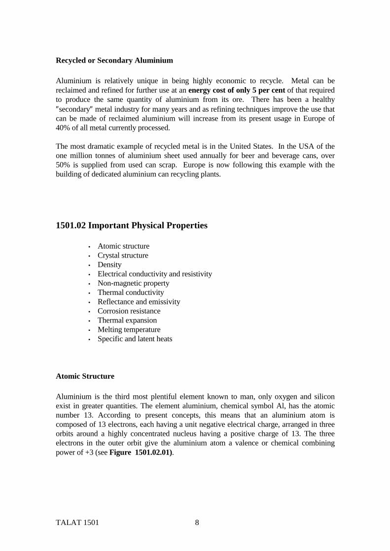
Density Lightness is the outstanding and best known characteristic of aluminium. The metal has an atomic weight of 26.98 and a specific gravity of 2.70, approximately one-third the weight of other commonly used metals; with the exception of titanium and magnesium (see Figure 1501.02.02). As with most metals the density decreases with increasing temperature. The addition of other metals in the amounts commonly used in aluminium alloys does not appreciably change the density (plus 3%, minus 2%), (see e.g. also Figure 1501.03.05), except in the case of Lithium alloys where the density of the alloy is reduced by up to 15%. Weight is important for all applications involving motion. Saving weight results in more payload or greater economy of operation. Saving weight also saves energy,
TALAT 1501 10
reduces vibration forces, improves the performance of reciprocating and moving parts, reduces tiredness when using manually operated equipment, offers lower shipping, handling and erection costs. Low weight combined with the high strength possible with special alloys has placed aluminium as the major material for aircraft construction for the past sixty years. Although purchased on a weight basis, metals are generally used on a volume basis, it is therefore important to compare the cost of aluminium with other materials on this basis (Figure 1501.02.02).
alu
Training in Aluminium Application Technologies
ALUMINIUM STEEL COPPER BRASS MONEL TITANIUM MAGNESIUM0
0.5
1
1.5
2
1
0.346 0.303 0.32 0.307
0.6
1.55
Volume per Unit Weight 1501.02.02
Electrical Conductivity and Resistivity The electrical conductivity of 99.99% pure aluminium at 200C is 63.8% of the International Annealed Copper Standard (IACS). Because of its low specific gravity, the mass electrical conductivity of pure aluminium is more than twice that of annealed copper and greater than that of any other metal (see Figure 1501.02.03). The resistivity at 200C is 2.69 microohm cm. The electrical conductivity which is the reciprocal of resistivity, is one of the more sensitive properties of aluminium being affected by both, changes in composition and thermal treatment. The addition of other metals in aluminium alloys lowers the electrical conductivity of the aluminium therefore this must be offset against any additional benefits which may be gained, such as an increase in strength. Heat treatment also affects the conductivity since elements in solid solution produce greater resistance than undissolved constituents.

TALAT 1501 11
The very good electrical properties of aluminium have made it an obvious choice for applications in the electrical industry, particularly in power distribution where it is used almost exclusively for overhead transmission lines and busbars. The first major aluminium transmission line was completed in 1898 in the USA: a 46-mile, three-phase installation for the Standard Electric Company of California, from Blue Lakes to Stockton. Its use later became much more general when it was found possible to reinforce the cable (usually alloy 1350) with galvanised steel wire which increased the spans without too much sag. Although this product is still used, high strength (6061 type) all aluminium multi-strand cables are now preferred for some installations because higher line tensions can be achieved which can be applied to increase the distance between the pylons or alternatively reduce their height.
alu
Training in Aluminium Application Technologies
CONDUCTIVITY OF METALS COMPARED
CONDUCTIVITY / UNIT WEIGHT
LENGTH OF CONDUCTOR
CONDUCTIVITY =1
RESISTIVITY (r )where
RESISTIVITY ( r) =RESISTANCE ( R ) X SECTION AREA
6061 ALLOY
1501.02.03Electrical Properties of Aluminium
ELECTRICAL PURITY Al6063 T6 AlCOPPERGOLDSILVER
ELECTRICAL PURITY Al6063 T6 AlCOPPERGOLDSILVER
1350 ALUMINIUMWITH GALVANISEDSTEEL CORE
Non-Magnetic Property Aluminium and its alloys are very slightly paramagnetic, as it has a magnetic permeability (m) slightly greater than one. The magnetic susceptibility χ (Chi), degree of magnetization/ applied magnetizing force, of 99.99 % purity aluminium is only 0.623 x 10⁻⁶, which for practical purposes is regarded as non magnetic (see Figure 1501.02.04). The relationship between m and χ is given by : m = 1 + 4^χ. Chi is influenced by alloying as follows: Cu decreases χ to 0.550 at 4.5% Cu (annealed) Cu decreases χ to 0.400 at 4.5% Cu (quenched) Fe in impurity quantities has no effect (FeAl3 has the same Chi value as aluminium)

TALAT 1501 12
Mn increases χ to 0.959at 1.38% Mn Cr increases χ to 0.669 at 0.63% Cr V reduces χ to 0.582 at 0.36% V The magnetic susceptibility is not sensitive to strain hardening, but varies slightly with temperature. The low magnetic characteristic of aluminium is of value in military ship structures where it has advantages of lightness and lower cost over other non-magnetic metals. It is also used to advantage in electronic equipment for screening where it may also double as heat sinks, usually in the form of finned extruded profiles. The requirement for manufacturers of electronic equipment to ensure that their products comply with EEC directives on Electronic Compatibility, has also led to an increase in the application of vacuum deposited aluminium films on to plastic enclosures. Special techniques have been developed to deposit thick layers of aluminium without the need for protective lacquering; these give very good shielding results and the non-magnetic properties ensure consistent operation over the life of the product.
alu
Training in Aluminium Application Technologies
0.64
0.56
0.48
0.40
0 2 4 6 8
ANNEALED
AS QUENCHED
COPPER %
MAGNETIC SUSCEPTIBILITYΧg x 106 at 30 °C
1501.02.04Magnetic Susceptibility of AlCu Alloy
Χg
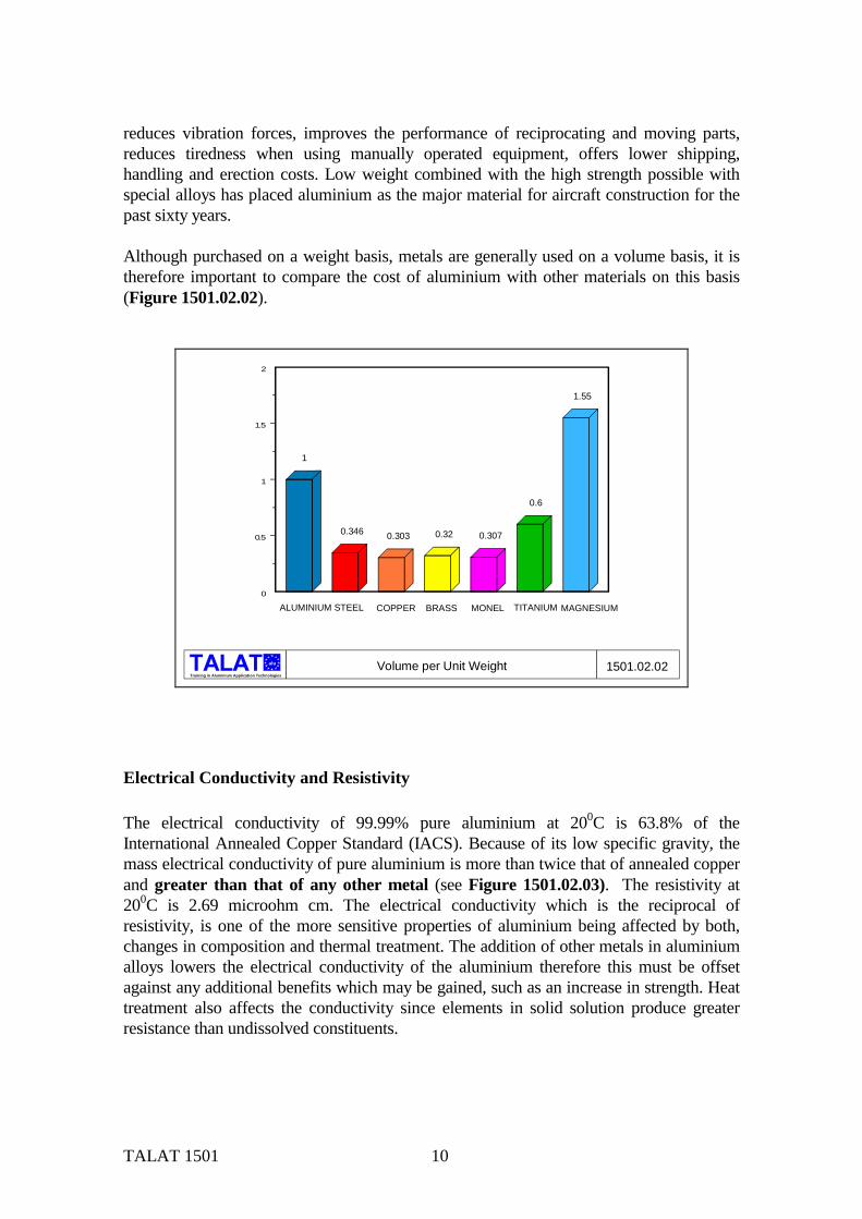
Thermal Conductivity The thermal conductivity, κ, of 99.99% pure aluminium is 244 W/mK for the temperature range 0-1000C which is 61.9% of the IACS, and again because of its low specific gravity its mass thermal conductivity is twice that of copper (see Figure 1501.02.05). Thermal conductivity can be calculated from electrical resistivity measurements using the formula κ =5.02λT x 10-9 +0.03, where κ is the thermal conductivity, λ is the electrical conductivity and T the absolute temperature in degrees Kelvin; this method is usually used to derive the values quoted in reference books. The thermal conductivity is reduced
TALAT 1501 13
slightly by the addition of alloying elements. Application of the formula has been found to be largely independent of composition with the exception of silicon. The combined properties of high thermal conductivity, low weight and good formability make aluminium an obvious choice for use in heat exchangers, car radiators and cooking utensils while in the cast form it is extensively used for I/C engine cylinder heads.
alu
Training in Aluminium Application Technologies
Copper
ALUMIN
IUM
Grey Iro
nBras
s
Copper
ALUMIN
IUM
Grey Iro
nBras
s
1.0
0.5
0
1.0
0.5
0
1.0
0.57
0.12
0.30
0.52
1.0
0.10 0.19
per UNIT WEIGHT
1501.02.05Thermal Conductivity of Aluminium Compared with other Metals
Thermal Conductivity of Aluminium Compared with other Metals
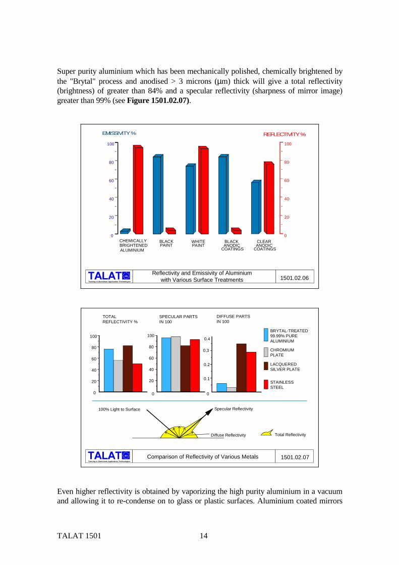
Reflectance and Emissivity Emissivity, the ease with which a substance radiates its own thermal energy, is closely allied to reflectivity; the best reflecting surface being the poorest emitter, and conversely the worst reflecting surface being the best emitter. Plain aluminium reflects about 75% of the light and 90% of the heat radiation that falls on it. The emissivity of the same piece of aluminium is, however, low (< 10% of that of a black body at the same temperature and with the same surroundings). The combined properties of high reflectivity and low emissivity give rise to the use of aluminium foil as a reflective insulating medium, either in dead air spaces or as a surface laminate combined with other insulating materials where it can also be arranged to provide the added benefit of an effective vapour barrier. The emissivity of the aluminium surface can be raised considerably by anodic treatment and is therefore a process that is employed in the construction of heat exchangers. E.g. clear anodic coatings raise the emissivity to between 35 and 65%, the phosphoric and chromic acid methods being the most effective in this respect. Black anodic coatings have an even greater effect and raise it as high as 95%. Figure 1501.02.06 shows the effect of various surface finishes on the emissivity of aluminium.
TALAT 1501 14
Super purity aluminium which has been mechanically polished, chemically brightened by the "Brytal" process and anodised > 3 microns (µm) thick will give a total reflectivity (brightness) of greater than 84% and a specular reflectivity (sharpness of mirror image) greater than 99% (see Figure 1501.02.07).
alu
Training in Aluminium Application Technologies
CHEMICALLY BLACK WHITE BLACK CLEAR0
20
40
60
80
100
0
20
40
60
80
100
BRIGHTENED PAINT PAINT ANODIC ANODICALUMINIUM COATINGS COATINGS
EMISSIVITY % REFLECTIVITY %
Reflectivity and Emissivity of Aluminium with Various Surface Treatments 1501.02.06
alu
Training in Aluminium Application Technologies
0
0.1
0.2
0.3
0.4
0
20
40
60
80
100
0
20
40
60
80
100
TOTAL REFLECTIVITY %
SPECULAR PARTS IN 100
DIFFUSE PARTS IN 100
100% Light to Surface Specular Reflectivity
Diffuse Reflectivity Total Reflectivity
Comparison of Reflectivity of Various Metals 1501.02.07
BRYTAL-TREATED99.99% PUREALUMINIUM
CHROMIUMPLATE
LACQUEREDSILVER PLATE
STAINLESSSTEEL
Even higher reflectivity is obtained by vaporizing the high purity aluminium in a vacuum and allowing it to re-condense on to glass or plastic surfaces. Aluminium coated mirrors
TALAT 1501 15
produced by this method are of particular interest to astronomers and in some ways are even more suitable than silver because they offer two important advantages. Firstly, an astronomical mirror coated with aluminium does not tarnish as quickly as silver and secondly, aluminium reflects ultra-violet light better. For these reasons the 60 and 100 inch mirrors of the Mount Wilson telescopes were "aluminized" as long ago as 1934.
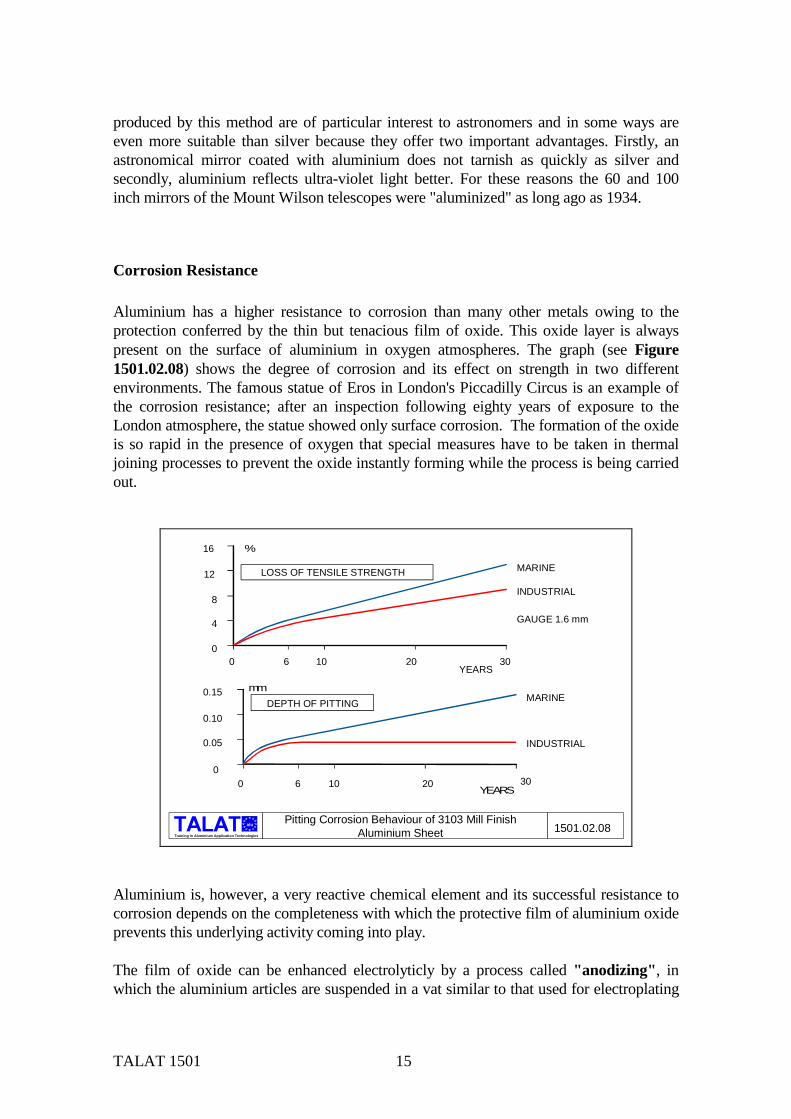
Corrosion Resistance Aluminium has a higher resistance to corrosion than many other metals owing to the protection conferred by the thin but tenacious film of oxide. This oxide layer is always present on the surface of aluminium in oxygen atmospheres. The graph (see Figure 1501.02.08) shows the degree of corrosion and its effect on strength in two different environments. The famous statue of Eros in London's Piccadilly Circus is an example of the corrosion resistance; after an inspection following eighty years of exposure to the London atmosphere, the statue showed only surface corrosion. The formation of the oxide is so rapid in the presence of oxygen that special measures have to be taken in thermal joining processes to prevent the oxide instantly forming while the process is being carried out.
alu
Training in Aluminium Application Technologies
0 6 10 20 300
0.10
0.15
0.05
MARINE
INDUSTRIAL
DEPTH OF PITTINGmm
YEARS
0 6 10 20 300
4
8
12
16
INDUSTRIAL
MARINELOSS OF TENSILE STRENGTH
%
YEARS
GAUGE 1.6 mm
1501.02.08Pitting Corrosion Behaviour of 3103 Mill Finish
Aluminium Sheet Aluminium is, however, a very reactive chemical element and its successful resistance to corrosion depends on the completeness with which the protective film of aluminium oxide prevents this underlying activity coming into play. The film of oxide can be enhanced electrolyticly by a process called "anodizing", in which the aluminium articles are suspended in a vat similar to that used for electroplating

TALAT 1501 16
but containing chromic, phosphoric or sulphuric acid solutions (Figure 1501.02.09). The anodic film also possesses the property of absorbing dyes thus enabling the metal to be tinted with attractive and enduring colours, thereby combining decoration with protection. Nearly all engineering metals are cathodic to aluminium and its alloys, therefore aluminium becomes sacrificial in the presence of an electrolyte. Exceptions to this situation are magnesium, cadmium and zinc which are anodic; for this reason cadmium and zinc are often used as a protection between aluminium and the other metal. 18/8, 18/8/2 and 13% Cr Stainless steels, titanium and chrome plate are further exceptions since they have a high potential difference to aluminium but form there own protective films which considerably reduce bimetallic effects (see Figure 1501.02.10).
alu
Training in Aluminium Application Technologies1501.02.09
CELL SIZE
METAL
A B C D E
A B+
Principles of Anodizing
THICKERANODICFILM
THINANODICFILM
BEFOREANODISING
AS "B"COATINGSTRIPPED
AS "D"REANODISEDTO RESTOREDIMENSIONS COATINGOF "B" ; THICKER MICROSTRUCTURE
OF ANODIC FILM
CELL WALLTHICKNESS
CURRENT ENTERING AND LEAVINGSOLUTION IN ANODISING
DIMENSIONAL CHANGES ONFORMATION OF ANODIC FILM
BARRIERLAYER
POREDIAMETER
alu
Training in Aluminium Application Technologies1501.02.10
Mg,Mg Base Alloys Attack on Al also
INDUSTRIALMARINE
RURAL
TOTAL IMMERSION
ATMOSPHERE
Bi-Metallic Corrosion at Junction ofAluminium with other Metals
Au,Pt,Rh,AgCu,Cu Alloys, "Ag" SolderSolder on Steel,CuNi,Ni AlloysSteel, Cast IronPb,SnSn/ Zn Plating on Steel
Al,Al Alloyswithout Cu or Zn
CdZn,Zn Alloys
TiStainless SteelChromium Plate
METAL COUPLED WITHALUMINIUM ORALUMINIUM ALLOY
Alloyed with Cu becomes more noble, with Zn less. AlZn alloys thus used as protective cladding for stronger AlCu alloys
Anodic to Al whichis protected
Form protective films.Where attack occursAl is corroded
Cathodic to Al whichis corroded
SEVERE ATTACKMINIMAL ATTACKMODERATE ATTACK
TALAT 1501 17
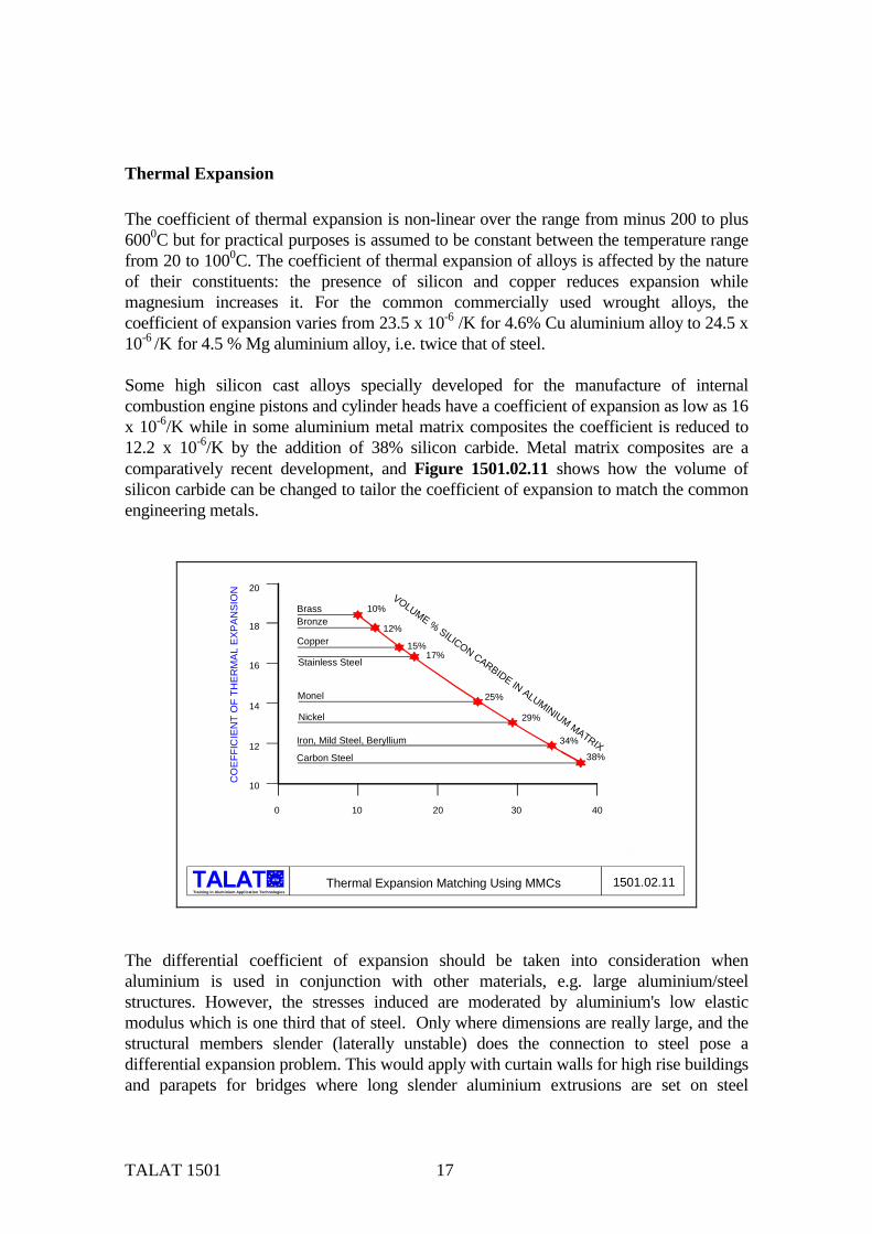
Thermal Expansion The coefficient of thermal expansion is non-linear over the range from minus 200 to plus 6000C but for practical purposes is assumed to be constant between the temperature range from 20 to 1000C. The coefficient of thermal expansion of alloys is affected by the nature of their constituents: the presence of silicon and copper reduces expansion while magnesium increases it. For the common commercially used wrought alloys, the coefficient of expansion varies from 23.5 x 10⁻⁶ /K for 4.6% Cu aluminium alloy to 24.5 x 10⁻⁶ /K for 4.5 % Mg aluminium alloy, i.e. twice that of steel. Some high silicon cast alloys specially developed for the manufacture of internal combustion engine pistons and cylinder heads have a coefficient of expansion as low as 16 x 10-6/K while in some aluminium metal matrix composites the coefficient is reduced to 12.2 x 10⁻⁶/K by the addition of 38% silicon carbide. Metal matrix composites are a comparatively recent development, and Figure 1501.02.11 shows how the volume of silicon carbide can be changed to tailor the coefficient of expansion to match the common engineering metals.
alu
Training in Aluminium Application Technologies
alu
0 10 20 30 40
20
18
16
14
12
10
10%
12%
15%17%
25%
29%
34%
38%
VOLUME % SILICON CARBIDE IN ALUMINIUM MATRIX
CO
EFFI
CIE
NT
OF
THER
MAL
EXP
ANSI
ON
BrassBronze
Copper
Stainless Steel
Monel
Nickel
Iron, Mild Steel, Beryllium
Carbon Steel
Thermal Expansion Matching Using MMCs 1501.02.11
The differential coefficient of expansion should be taken into consideration when aluminium is used in conjunction with other materials, e.g. large aluminium/steel structures. However, the stresses induced are moderated by aluminium's low elastic modulus which is one third that of steel. Only where dimensions are really large, and the structural members slender (laterally unstable) does the connection to steel pose a differential expansion problem. This would apply with curtain walls for high rise buildings and parapets for bridges where long slender aluminium extrusions are set on steel

TALAT 1501 18
frameworks. In these cases slip joints, plastic caulking and other stress-relieving devices are usually needed (see Figure 1501.02.12). In cases where the structure is stiff and unlikely to buckle such as an aluminium superstructure on a steel hulled ship all joints are now made rigid and the differential expansion is accepted as a compressive or tensile stress (Figure 1501.02.12). . Another form of dimensional change, which does not directly affect the user of aluminium but is important in the production of castings, is the contraction of the metal on solidification; this is dependant upon alloy and is between 1 and 2% (comparative figures for iron, steel and brass are 1%, 2%, and 1.5%, respectively).
alu
Training in Aluminium Application Technologies1501.02.12
C L
EXPANSION68 56
35
690 OVERALL
SECTION C - C
56 56 56
C
C
INDUCED TENSION0INDUCED COMPRESSION
WELD
WELD
ALUMINIUM
ALUMINIUM
STEEL
STEEL
ALUMINIUM / STEEL TRANSITION JOINT
RAIL JOINT - BRIDGE EXPANSION UP TO 50mm TOTAL MOVEMENT
Sliding and Rigid Joints ofAluminium/ Steel Structures
ZERO STRESS
JOINT SYMMETRICALABOUT C / L
10 X 35 SLOTS FRONT& REAR OF JOINT
10 DIA HOLE FRONT& REAR FOR RAIL JOINT
RIGIDJOINT
SLIDINGJOINT
TRANSITION PIECE- AREA TO BEPROTECTED -
Melting Temperature The melting point of aluminium is sensitive to purity, e.g. for 99.99% pure aluminium at atmospheric pressure it is 6600C but this reduces to 6350C for 99.5% commercial pure aluminium. The addition of alloying elements reduces this still further down to 5000C for some magnesium alloys under certain conditions. The melting point increases with pressure in a straight line relationship to 9800C at 50 kbar. The difference between the melting points of two alloys of aluminium is used to advantage in the manufacture of aluminium heat exchangers, where the fins are made from aluminium-manganese (3103) or (3003) alloy clad with 5, 7.5% or 10% silicon alloy. The assembled heat exchanger is heated to the temperature which will just melt the cladding while allowing the core to remain solid; this causes the molten cladding alloy to flow by

TALAT 1501 19
capillary action to the joints which become structural on cooling (Figure 1501.02.13). The highly controlled heating necessary in this brazing process is done using either a vacuum furnace, controlled atmosphere furnace, or flux bath.
alu
Training in Aluminium Application Technologies
SOLIDIFIED CLADDING
1501.02.13
BEFORE BRAZING AFTER BRAZING
3003 (Al Mn) CORE
Al Si 10% CLADDING
626
610
595
°C
Brazing of Aluminium Using Clad Sheet
MELTING POINT COREFURNACE TEMPERATURE +/- 3
MELTING POINT CLADDING
Specific and Latent Heats Aluminium has a relatively high specific heat when compared with other metals on a weight basis, i.e. 921 J/kg at 1000C which is higher than that of any common metal except magnesium (1046); iron and steel are about 500 and copper and brass 377. On a volume basis, however, the heat capacity of aluminium is less than any of the heavier metals. 1501.03 Aluminium Alloy Availability
• The four digit system for wrought alloy identification • Alloy systems
− Unalloyed aluminium − Aluminium-copper alloys − Aluminium-manganese alloys − Aluminium-silicon alloys − Aluminium-magnesium alloys − Aluminium-magnesium-silicon alloys − Aluminium-zinc-magnesium and aluminium-zinc-magnesium-copper
alloys − Aluminium-plus other elements which do not fall into any of the patterns outlined above
• The five digit system for cast alloy identification − Unalloyed aluminium
TALAT 1501 20
− Aluminium alloys, ingots and casting Aluminium is the backbone of the aerospace industry, is used to assist with cooking and packaging, assist in the manufacture of high grade steel and is the base for a versatile paint. Aluminium is a light and attractive metal exhibiting a high degree of corrosion resistance in normal corrosive environments. It is also soft, hard, easy to weld, difficult to weld, and a host of other seemingly conflicting characteristics. If this sounds confused, it is. The properties of a particular aluminium product depend on the alloy chosen. The term aluminium refers to a family of alloys. Knowledge of these alloys is the key to the effective use of aluminium. Outlined below is the family of aluminium alloys which are readily available commercially.
The Four Digit System for Wrought Alloy Identification As a major step towards alignment of Aluminium and Aluminium Alloy compositions on an international basis, most countries have agreed to adopt the 4 digit classification for wrought alloy composition designation. This system is administered by the Aluminium Association (AA), Washington USA, who compile the ″Registration record of International Alloy Designations and Chemical Composition Limits for Wrought Aluminium Alloys″. The European reference for the alloys will be identified with the preface EN and AW which indicated European Normative Aluminium Wrought alloys. In all other respects the alloy numbers and composition limits are identical to those registered by the Aluminium Association (Figure 1501.03.01).

TALAT 1501 21
alu
Training in Aluminium Application Technologies1501.03.01
XXXX
(X)(X)(X)(X)
XXX
XXXX
XXXX
Aluminium Alloy Designation System
WROUGHTALLOYS*)EN AW-
CASTINGALLOYS*)
EN AB-EN AC-EN AM-
1XXX02XXX04XXX05XXX07XXX08XXX09XXX0
None (min. 99.00% Al)CuSiMgZnSnMaster Alloys
Major alloyingelement
Atoms in solution
Workhardening
Precipitationhardening
Non-heattreatablealloys
Heattreatablealloys
Aluminium Alloy Designation System (CEN)
1XXX3XXX4XXX5XXX
2XXX6XXX7XXX8XXX
None (min. 99.00% Al)MnSiMg
CuMg + SiZnOther
*) letters preceding the alloy numbers have the following meaning EN = European Standard A = Aluminium B = Ingot C = Cast Alloy M = Master Alloy W = Wrought Alloy
Sources: according to EN 573; prEN 1780
The first of the four digits in the designation indicates the alloy group in terms of the major alloying elements, viz, 1XXX Aluminium of 99,00% minimum purity and higher 2XXX Copper 3XXX Manganese 4XXX Silicone 5XXX Magnesium 6XXX Magnesium and Silicon 7XXX Zinc 8XXX Other elements 9XXX Unused series 1XXX Group. In this group for minimum purities of 99,00% and greater, the last
two of the four digits indicate the minimum percentage of aluminium. For example, 1070 indicates aluminium purity of 99,70%.
The second digit indicates modifications in impurity limits or alloying elements. If the second digit is zero it indicates unalloyed aluminium having natural impurity limits; integers 1-9 indicated special control of one or more individual impurities or alloying elements. For example, 1145 indicates aluminium of 99,45% minimum purity with the second digit 1 indicating special control of Iron and Silicon.

TALAT 1501 22
2XXX to 8XXX Groups In these groups the last two of the four digits have no special
significance but serve only to identify the different alloys in the group. The second digit indicates alloy modifications; if it is zero it indicates the original alloy.
National variations consisting of minor changes in the chemical
composition of a standard alloy are accepted in the international system and are identified by a suffix letter after the numerical designation, e.g. 6101A. Experimental alloys are indicated by the prefix X, eg. X2030.
Alloy Systems Figures 1501.03.02 - 05 inclusive show the relationship between the properties and characteristics of the various alloy groupings. For instance, natural, unalloyed aluminium possesses an ultimate tensile strength of about 70 Mpa which compares to 700 MPa and above for some of the 7XXX series (Figure 1501.03.02).
alu
Training in Aluminium Application Technologies
1XXX 3XXX 5XXX 6XXX 7XXX 2XXX 7XXX
CHEMICAL CODE
STRENGTH
Al Al Mn Al Mg Al Mg Si Al Zn Mg
Soft Low Medium Medium High High
PROPERTY
Tensile Strength, Hardness and Impact Sensitivity
Ductility (Elongation)
The Effect of Alloying Elements on Tensile Strength, Hardness, Impact Sensitivity and Ductility 1501.03.02
AlloyType
Al CuMg Si
Al ZnMg Cu

TALAT 1501 23
alu
Training in Aluminium Application Technologies
1XXX 3XXX 5XXX 6XXX 7XXX 2XXX 7XXX
CHEMICAL CODE
STRENGTH
Al Al Mn Al Mg Al Mg Si Al Zn Mg
Soft Low Medium Medium High High
PROPERTY
Anodising
Weldability
The Effect of Alloying Elements onWeldability and Anodising 1501.03.03
Al CuMg Si
Al ZnMg Cu
AlloyType
alu
Training in Aluminium Application Technologies
1XXX 3XXX 5XXX 6XXX 7XXX 2XXX 7XXX
CHEMICAL CODE
STRENGTH
Al Al Mn Al Mg Al Mg Si Al Zn Mg
Soft Low Medium Medium High High
PROPERTY
The Effects of Alloying Elements onCorrosion Resistance and Fatigue Strength 1501.03.04
AlloyType
Al CuMg Si
Al ZnMg Cu
Corrosion Resistance
Fatigue Strength
alu
Training in Aluminium Application Technologies
1XXX 3XXX 5XXX 6XXX 7XXX 2XXX 7XXX
CHEMICAL CODE
STRENGTH
Al Al Mn Al Mg Al Mg Si Al Zn Mg
Soft Low Medium Medium High High
PROPERTY
Density
Young's Modulus
The Effect of Alloying Elements on Density and Young's Modulus 1501.03.05
AlloyType
Al CuMg Si
Al ZnMg Cu
TALAT 1501 24
Wrought aluminium alloys are those in which the cast ingot is mechanically worked by processes such as rolling, drawing, extruding or forging, These alloys fall into several groups; each group being distinguished by one main alloying constituent, as outlined in further detail below. All wrought alloys are further divided into two general classes namely the "heat-treatable" and "non-heat treatable" alloys.
Unalloyed Aluminium EN system EN AW-1xxx e.g. 1200 Commercially pure aluminium (99.0% pure) is soft, ductile and of little structural value, but as extracted it normally contains up to 1.5% impurities; mainly iron and silicon. These have a marked effect on the properties of the metal, so that, with the further hardness acquired during rolling, commercial purity aluminium has a useful degree of strength and is widely produced in sheet form. It is very ductile in the annealed condition, has excellent corrosion resistance and is ideal for use in the food and chemical industries. It is rolled to foil thickness for use in food, confectionery and cigarette packaging and has even been used for making shaped panels for vehicles where its high elongation was of prime importance for the forming processes involved.

TALAT 1501 25
Aluminium - Copper Alloys EN system EN AW - 2XXX e.g. 2014 With copper as the principle element, these alloys require solution heat treatment to achieve optimum mechanical properties, which can exceed that of mild steel. A typical example here is 2014, a composition of Cu Si Mn Mg 4,0-4,58 0,6-0,9% 0,4-1,2% 0,5-0,9% giving typical tensile properties of 460 Mpa. This group of alloys with additions such as Pb (X2030) or Pb + Bi (2011) give the best machinability but there is a trend to avoid these additions because of potential scrap contamination. Typical alloys in this group are 2017, 2024, 2014 X2030 and 2011. Generally, these alloys have limited cold formability, except in the annealed condition, and less corrosion resistance than other alloys; they are therefore generally anodised for protection from aggressive environments. They are also more difficult to weld. Alloys in this family are particularly useful for aircraft and military applications.
Aluminium - Manganese Alloys EN system EN AW - 3XXX e.g. 3004 The addition of approximately 1% manganese increases the strength by approximately 10 - 15% compared with 1200, without any major loss in ductility. This non-heat treatable alloy generally finds a wide application where greater strength than 1200 is required without any major loss in corrosion. Major end uses of the common alloys in this range include roofing sheet (3105 + 3103) and vehicle panelling (3103).
Aluminium - Silicon Alloys EN system EN AW 4XXX eg 4043 Silicon can be added to aluminium alloys in quantities sufficient to cause a substantial lowering of the melting point. For this reason this alloy system is used entirely for welding wire and brazing filler alloys, where melting points lower than the parent metal are required. In themselves these alloys are non-heat-treatable but in general they pick up enough of the alloy constituents of the parent metal to respond to a limited degree of heat treatment.

TALAT 1501 26
Aluminium - Magnesium Alloys EN system EN AW 5XXX eg 5056 This series of alloys is non heat-treatable and exhibits the best combination of high strength with resistance to corrosion (as indicated by its frequent use in marine/sea water applications). This series also exhibits good weldability but when the Mg level exceed 3% there is a tendency for stress corrosion resistance to be reduced, dependent on the temper used and temperature of operation. Uses: pressure vessels, bulk road and rail vehicles, ships structures, chemical plant.
Aluminium - Magnesium - Silicon Alloys EN Systems EN AW - 6XXX eg 6063 This group of heat-treatable alloys uses a combination of magnesium and silicon (magnesium Silicide) to render it heat-treatable. These alloys find their greatest strength, combined with good corrosion resistance, ease of formability and excellent ability to be anodised. Typical alloys in this group include 6061, 6063 and 6082 used for building structure applications, and land and see transport applications.
Aluminium-Zinc-Magnesium and Aluminium-Zinc-Magnesium-Copper Alloys EN Systems EN AW - 7XXX eg 7075 This group of alloys exhibits the highest strength as far as aluminium is concerned and in many cases they are superior to that of high tensile steels. It is the combination of zinc and magnesium which makes the 7XXX alloys heat-treatable and gives rise to their very high strength. A typical example here is 7075 with a composition of: Zn Mg Cu 5,0-6,0% 2,0-3,0% 1,0%-2,0% giving a typical tensile strength of 580Mpa. This group of alloys is, however, relatively difficult to fabricate and requires a very high degree of technology to produce. It is mainly used in military applications.
TALAT 1501 27
Aluminium - plus other elements which do not fall into any of the patterns outlined above EN System EN AW - 8XXX e.g. 8011, a totally mixed bag of alloys ranging from 8011 for bottle capping to 8091 for Lithium alloy aircraft sheet.
The Five Digit System for Cast Alloy Identification The new European reference for alloys will be identified with the preface EN followed by a blank space followed by A which indicates aluminium then B,C, or M which indicate respectively ingots for re-melting, casting or master alloys. The cast alloy numbering system for Europe, Figure 1501.03.01, will use a five figure format as follows:
Unalloyed Aluminium The first of the five figures in the designation system is the number 1 (as used in wrought aluminium for aluminium for aluminium 99,00% minimum and greater). The second of the five figures in the designation system is the number 0. The third and fourth figures indicate the minimum aluminium percentage. They are the same as the two figures to the right of the decimal point in the minimum percentage, when it is expressed to the nearest 0.01 percent. Example AB-10 97 0 for Al 99, 97 The fifth figure is 0, 1 or 2 depending on the application being general or specific.
Aluminium Alloys, Ingots and Casting For a given alloy, ingot and casting have the same numerical designation. The first of the five figures in the designations indicates the major alloying element and is the same as that used in the wrought aluminium system. - Copper 2XXX

TALAT 1501 28
- Silicon 4XXX - Magnesium 5XXX - Zinc 7XXX The second of the five figures in the designation indicates the alloy group. -2 1 XXX : A1Cu -4 1 XXX : A1SiMgTi -4 2 XXX : A1Si7Mg -4 3 XXX : AlSi10Mg -4 4 XXX : A1Si -4 5 XXX : AlSiCu -4 6 XXX : AlSi9Cu -4 7 XXX : AlSi (Cu) -4 8 XXX : AlSiCuNiMg -5 1 XXX : AlMg -7 1 XXX : AlZnMg The third figure is arbitrary. The fourth figure is generally 0. The fifth figure is always 0 for CEN alloys and never 0 for AECMA alloys.

TALAT 1501 29
1501.04 Basic Physical Metallurgy
• Work hardening • Dispersion hardening • Solid solution hardening • Precipitation hardening • Temper designations non heat-treatable alloys • Temper designations heat-treatable alloys • Common alloys and applications
There are four basic ways in which aluminium can be strengthened: work hardening, dispersion hardening, solid solution hardening and precipitation hardening. These hardening processes are effective because they produce conditions that impede the movement of dislocations. Dislocations are faults that enable metal crystals to slip at stresses very much below those that would be required to move two perfect crystal planes past one another.
Work Hardening Whenever aluminium products are fabricated by rolling, extruding, drawing, bending, etc., work is done on the metal. When work is done below the metal's recrystallisation temperature (cold work), it not only forms the metal, but also increases it strength due to the fact that dislocations trying to glide on different slip planes interact causing a "traffic jam" that prevents them from moving. Fabricating processes carried out above the metal's recrystallization temperature (hot work) do not normally increase strength over the annealed strength condition. With non heat-treatable wrought alloys, cold work is the only way of increasing strength. With heat treatable alloy, cold work applied after heat treating can increase strength still further. Work hardening of non heat treatable aluminium magnesium and pure aluminium alloy is shown in Figure 1501.04.01.

TALAT 1501 30
alu
Training in Aluminium Application Technologies1501.04.01
300
250
200
150
100
5040
30
20
10
00 20 40 60 80
STRENGTH
DUCTILITY
% REDUCTION IN AREA BY COLD WORK SLIP PLANES
Work Hardening of Aluminium
ELONGATION% ON 50 mm
ULTIMATETENSILESTRENGTH N/ mm2
DEFORMATION OFALUMINIUM GRAINUNDER PRESSURESTRONG ALLOYS
STRONG ALLOYS
COMMERCIALLY PURE ALUMINIUM
COMMERCIALLY PURE ALUMINIUM
Dispersion Hardening Fine particles of an insoluble material are uniformly distributed throughout the cristal lattice in such a way as to impede the movement of dislocations (eg 3000 series). With aluminium, dispersion-hardening may be achieved in two ways: − by the addition of alloying elements that combine chemically with the metal or each
other to form fine particles that precipitate from the matrix − by mixing particles of a suitable substance (for example A1203) with powdered
aluminium and then compacting the mixture into a solid mass.
Solid Solution Hardening Most alloys are solid solutions of one or more metals dissolved in another metal: either the alloying of atoms take over the lattice positions of some of the base-metal atoms (substitutional solid solutions) or they occupy spaces in the lattice between the base-metal (interstitial solid solutions). In both cases, the base-metal lattice is distorted, retarding the movement of dislocations and hence strengthening the metal. The 5000 series with magnesium as the solute is a good example. Most aluminium alloys reflect some solid solution hardening as a result of one or more elements being dissolved in the aluminium base, each element's contribution to the strength of the alloy is roughly additive. Usually these alloys are further strengthened by heat treatment or by work hardening.

TALAT 1501 31
Precipitation Hardening Precipitation hardening is a two stage heat treatment. It can be applied only to those groups of alloys which are heat treatable (i.e. 2000, 6000 and 7000 wrought series). Firstly, a supersaturated condition is produced by solution heat treatment. Secondly the "ageing" process that occurs after quenching may be accelerated by heating the alloy until a second and coherent phase is precipitated. This coherent phase strengthens the alloys by obstructing the movements of dislocations. Solution treatment involves heating the alloy to a temperature just below the lowest melting point of the alloy system, holding at this temperature until the base metal dissolves a significant amount of the alloying elements (Figure 1501.04.02). The alloy is then rapidly cooled to retain as much of the alloying elements in solution as possible and so produce a supersaturated solid solution. This supersaturated condition is usually unstable and therefore heat-treatable alloys are used in this condition, i.e. T4.
alu
Training in Aluminium Application Technologies1501.04.02
OVER-AGING
COALESCED
AGING
SUPER-SATURATED
PRECIPITATE
Al
CuAl2
Al + CuAl2
800
700
600
500
400
300
200
100 0 1 2 3 4 5 6 7
LIQUID
°C
% Cu
Metallurgy of Precipitacion Hardening (e.g Al -Cu System)
SOLID SOLUTION ofALUMINIUM and COPPER
SOLID SOLUTION ofALUMINIUM and COPPERwith PARTICLES of CuAl2
LIQUID: and SOLIDSOLUTION
SOLUTION HEAT TREATMENTTEMPERATURE
CuAl2
RAPIDCOOLING
SLOWCOOLING
After solution heat-treatment most heat-treatable alloys exhibit some age-hardening at room temperature. The rate and extent of natural age-hardening at room temperature varies from alloy to alloy. For example, 2024 reaches a stable condition in four days and is therefore widely used in naturally aged tempers. By contrast, 7075 and most other aluminium-zinc-magnesium-copper alloys continue to age-harden indefinitely at room temperature and are seldom used in naturally aged temper.

TALAT 1501 32
Heating above room temperature accelerates the precipitation reaction, in practice, therefore, precipitation-hardened alloys are usually ″artificially aged' (precipitation heat treated) to develop maximum properties as quickly as possible. The temperature range within which control of the precipitation reactions is feasible is 120-180°C. The actual temperature depends on such variables as the alloy, the properties desired and production schedule. An aluminium alloy that responds to precipitation hardening must contain amounts of soluble alloying elements that exceed the solid solubility limit at room temperature. Figure 1501.04.02. shows one corner of the phase diagram of such an alloy. In addition, the alloy must be able to dissolve the excess of soluble alloying elements and then to precipitate them (or the compounds they form) as distinctive constituents within the crystal lattice. The constituents precipitated must have a structure different from the solid solution. Careful control of this precipitation reaction is essential, otherwise the hardening constituents become too coarse and contribute little to the strengthening. The effect of time and temperature on the precipitation process is shown in Figure 1501.04.03.
alu
Training in Aluminium Application Technologies
1501.04.03
0 1 2 3 4 5 6 7 8
325
300
275
250
225
UTS
MPa
SOAKING TIME (HOURS)
Ageing-Curves for Aluminium Alloy 6082
SOAKINGTEMPERATURE
185°C
200 °C170°C
215°C
Temper Designations Non Heat-Treatable Alloys These are alloys in which the mechanical properties may be enhanced by the amount of cold work introduced after the last annealing operation. The properties so obtained will be reduced by subsequent heating and cannot be restored except by additional cold work.

TALAT 1501 33
In the non heat-treatable alloys there are generally six available tempers (Figure 1501.04.04). It should be remembered, however, that all tempers are not always available for all alloys. The most common tempers range from annealed, designated by ″0″, to the full-hard tempers designated by temper HX8. The term H8 refers to the maximum amount of cold work which is commercially practical for the particular alloy. An alloy in the HX8 condition will exhibit a 75% increase in strength over the same alloy in the ″0″ condition. Between the annealed and the HX8 state there are generally three intermediate levels of hardness referred to as: Quarter hard HX2 Half hard HX4 Three quarters hard HX6 Products are produced in the ″F″ temper, are defined as "as fabricated". ″F″ represents an undefined strength enhancement above the annealed state ″0″.
alu
Training in Aluminium Application Technologies1501.04.04
XXXX -F-O
-H1-H2-H3
-HX2-HX4-HX6-HX8
-T2-T4-T5-T6-T8
as-fabricatedannealed
Work-hardened and partially annealedWork-hardened only
Work-hardened and stabilized by low temperature treatment
Quarter-hardHalf-hardThree-quarter-hardFully-hard
Cooled from an elevated temperature and naturally agedSolution heat-treated and naturally agedCooled from an elevated temperature shaping process and artifically agedSolution heat treated and artifically agedSolution heat-treated, cold worked and aged
XXXX
XXXX
Degree of cold working
A Selection of Common Temper Designations forAluminium Alloys
NON-HEATTREATABLE
ALLOYS
HEATTREATABLE
ALLOYS
Temper Designations Heat-Treatable Alloys These are alloys in which the mechanical properties may be changed by heat treatment. Heat is used to enhance strength but can also be used to decrease strength through annealing to assist with forming; these alloys can also be re-heat-treated after annealing or forming to restore their original properties, This is a major difference compared with non heat-treatable alloys (Figure 1501.04.04).

TALAT 1501 34
The major tempers in this area are designated and defined according to international standards (AA, ISO, CEN): 0 Fully annealed T3 Solution heat-treated, cold worked out, naturally aged T4 Solution heat-treated and naturally aged T5 Cooled from an elevated temperature shaping process and
then artificially aged T6 Solution heat-treated, artificially aged T8 Solution heat-treated, cold worked and artificially aged The T4 is produced by "solution heat treatment" which, as mentioned previously, consists of heating the alloy to a predetermined temperature just below its melting point, at which point some of the alloy constituents dissolve and are then taken into what is referred to as "solid solution". To ensure that this situation is maintained the material is quenched rapidly. An example of this is 2014 where the temperature is raised to 500°C ± 5% before quenching in water.
Common Alloys and Applications The following list gives a brief survey of commonly used aluminium alloys, their characteristics and common uses:
Alloy 1050/ 1200 2014A 3103/ 3003 5251/ 5052 *5454 *5083/ 5182
Alloy Characteristics Non heat-treatable. Good formability, weldability and corrosion resistance Heat-treatable. High strength. Non- weldable. Poor corrosion resistance Non-treatable. Medium strength work hardening alloy. Good weldability, formability and corrosion resistance. Non-heat-treatable. Medium strength work hardening alloy. Good weldability, formability and corrosion resistance. Non-heat-treatable. Used at temperatures between 650°C and 200°C. Good weldability and
Common Uses Food and Chemical Industry Airframes Vehicle panelling, structures exposed to marine atmospheres, mine cages Vehicle panelling, structures exposed to marine atmospheres, mine cages. Pressure vessels, road and rail tankers. Transport of Ammonium Nitrate, Petroleum tankers, Chemical plants. Pressure vessels and road transport
Form S.P E.P S.P.E S.P S.P S.P.E

TALAT 1501 35
*6063 *6061/ *6082 *6005A 7020 7075
corrosion resistant. Non-heat-treatable. Good weldability and corrosion resistance. Very resistant to sea water, industrial atmospheres. A superior alloy for cryogenic use (in annealed condition) Heat-treatable. Medium strength alloy. Good weldability and corrosion resistance. Used for intricate profiles. Heat-treatable. Medium strength. Good weldability and corrosion resistance. Heat-treatable. Properties very similar to 6082. Preferable as air-quenchable, therefore has less distortion problems. Not notch-sensitive. Heat-treatable. Age-hardens naturally, therefore will recover properties in heat-affected zone after welding. Susceptible to stress corrosion. Good ballistic deterrent properties. Very high strength. Heat-treatable. Non-weldable. Poor corrosion resistance.
applications below 65°C. Shipbuilding structures in general. Architectural extrusions (internal and external) window frames, irrigation pipes. Stressed structural members, bridges, cranes, roof trusses, beer barrels Thin wall wide extrusions Armoured vehicles, military bridges, motor cycle and bicycle frames Airframes
E S.P.E E P.E E.P
* Most commonly used alloys; S = Sheet; P = Plate; E = Extrusions Some differences in properties and characteristics for the different alloys and alloy groups can also be appreciated from Figures 1501.03.02 till 05.
TALAT 1501 36
1501.05 Aluminium Alloys ; Mechanical Properties
• Tensile strength • Strength/weight ratio • Proof stress • Elastic properties • Elongation • Compression • Bearing • Shear • Hardness • Ductility • Creep • Properties at elevated temperatures • Properties at low temperatures • Impact strength • Fracture characteristics • Fatigue
Tensile Strength Behaviour under tension is generally considered the first yardstick of an engineering material, and Figure 1501.05.01 shows typical tensile stress/strain curves for four different aluminium alloys and compares them with a range of engineering metals. The alloys are: 99.5% pure aluminium (1050A) in the fully annealed state, suitable for deep pressing; a 4.5% magnesium-aluminium alloy (5083) after strain-hardening, by rolling, to the ″half-hard″ temper, used in marine and welded structures; a magnesium-manganese-silicon alloy 6082 after solution treatment and ageing to the fully heat treated ″T6″-condition, used in commercial structures and a zinc-magnesium-copper-aluminium alloy 7075 in the fully heat treated condition used in aircraft construction.
Strength/Weight Ratio As can be seen from Figure 1501.05.01 the high tensile steels have the highest strengths of all the metals. These are followed by Titanium and the aircraft aluminium alloys and some way below these the commercial structural alloys 5083-H12 and 6082-T6. If we now consider the strength available for a given mass by dividing the tensile strength by the density we get quite a different picture (Figure 1501.05.02). We now find the 7075 at the top with the commercial structural alloys moving to the mid range above the common mild steel.

TALAT 1501 37
alu
Training in Aluminium Application Technologies
STRAIN %
STR
ESS
[ N /
mm
² ]
1 2 3 4 5 6 7
1200
1100
1000
900
800
700
600
500
400
300
200
100ALUMINIUM 1050 A
ALUMINIUM 5083 H12ALUMINIUM 6082-T6
ALUMINIUM 7075-T6
HIGH TENSILE STEEL - ALLOY
TITANIUM 6AL - 4V
COPPER HARD DRAWN
MILD STEEL
MAGNESIUM AECMA MG-P-61
1501.05.01Stress-Strain Curves of Aluminium in Comparision
with Various Metals and Alloys
alu
Training in Aluminium Application Technologies
100
200
1 2 3 4 5 6 7 STRAIN %
AIRCRAFT ALUMINIUM 7075-T6
TITANIUM 6AL - 4V
STEEL - ALLOYMAGNESIUM AECMA MG -P-61
ALUMINIUM 6082-T6STRUCTURALALUMINIUM 5083 H12
COPPER HARD DRAWN
PURE ALUMINIUM 1050 A
MILD STEEL
NON-STRUCTURAL
STRESSDENSITY
= N/mm²g/cm³
1501.05.02Density-Related Strength of Aluminium in
Comparision with Various Metals and Alloys
Proof Stress With mild steel there is a clearly defined point on the stress strain curve at which the elastic limit is reached; this ″yield point″ is followed by a sharp reduction in the stress before the metal exhibits a plastic flow region with stress again increasing with strain until the ultimate stress is reached and the stress reduces to the point of failure.

TALAT 1501 38
In most cases no clearly defined elastic limit or yield point is to be seen on stress/strain curves for aluminium alloys, this is apparent by looking at Figure 1501.05.03. For this reason the point of departure from the elastic range has to be defined arbitrarily. For convenience in routine testing, a point is chosen at which the permanent deformation is easily measured: at one time, a permanent set of 0.1% of the original gauge length was used. Today, however, 0.2% is the international norm. The stress at which a 0.2% set is observed is called the ″0.2% proof stress″ and, because it reveals the onset of plastic movement, is often of more value to the designer than the ultimate stress. Figure 1501.05.03 shows how it is obtained from a stress/strain diagram.
alu
Training in Aluminium Application Technologies
0.2 0.4 0.6 0.8 1.0 1.2
500
400
300
200
100
STRESSMPa
STRAIN %
ALUMINIUM
STEEL
0.2% STRAIN LIMIT
UPPERYIELDLIMIT
A B C
1501.05.03Plastic Yield Behaviour of Aluminium and Mild Steel
Some alloys, notably the heavily strain-hardened ones, have a high ratio of proof strength to ultimate stress; in 1200 H8 for example the 0.2% proof stress is 140 MPa and the ultimate stress 150 MPa. Generally, the ratio of proof to ultimate varies from 40% for soft tempers to 95% for the hardest; in the fully heat treated alloys it is about 85%. Although a high proof stress is in itself an advantage, a high proof stress/ultimate stress ratio implies a low ductility. Where strain is the criterion for design, it follows that the imposed stress would be one third in an aluminium member compared to one in steel. If we compare the curves for a similar strength aluminium and steel (shown in Figure 1501.05.03) and consider a 0.1% strain by drawing a vertical line at A the stress in the steel is 200 MPa whereas in the aluminium is only 66.6 MPa. It can also be seen from the graph that a strain of 0.3% (line B) is necessary to induce the same stress in the aluminium member. It is also worth noting that the aluminium represented by the curve in Figure 1501.05.03 would still be

TALAT 1501 39
in the elastic range at 0.38% strain (line C) while the steel subjected to the same rate of strain would have entered the plastic range. The area under the tensile stress-strain curve to the point of failure provides a measure of the capacity of a material to absorb energy under simple tensile loading.
Elastic Properties From Figure 1501.05.03 it can be seen that for the initial part of the stress-strain curve the strain per unit increase of stress is much higher for aluminium than for steel, measurement shows that it is three times higher. The slope of this part of the curve determines the Modulus of Elasticity (Young’s Modulus) e.g. stress divided by strain. It follows therefore that the Modulus of Elasticity for aluminium is one-third that of steel, being between 65500 and 72400 MPa for most aluminium alloys. From the information already given it is clear that when a steel structural member is replaced by one of identical form in an aluminium alloy the weight will be one third but the elastic deflection will be about three times as large. From this we can deduce that an aluminium member of identical dimension to one in steel will absorb three times as much energy, but only up to the point where the stress in the aluminium remains below the limit of proportionality. It is worth noting that stiffness is defined as the product of the Modulus of Elasticity and the Moment of Inertia of a section (E x I) and it is this which determines the deflection when subjected to a bending load. This allows the application of another attribute of aluminium, its ability to be made into a variety of complex structural shapes by extrusion. The extrusion process provides the designer with the opportunity to shape the metal to achieve maximum efficiency in the design of a section usually by making it deeper. However, making a section deeper often sacrifices some of the potential weight saving with the result that it only weighs about half that of the steel member instead of a third. Figure 1501.05.04 shows two different approaches of saving weight when using aluminium instead of steel for the main beams of a road trailer. All sections have the same bending stiffness, the aluminium 'I' beam has been designed with a maximum overall extrusion dimension and minimum extrusion thickness, while the aluminium box beam has been designed to the same width as the steel beam but with additional special features to improve the build. The aluminium I beam exhibits an improved section modulus and consequently a lower induced stress in bending in addition to a 57% weight saving, but because of its slender shape has inherent poor torsional stability. The aluminium box beam exhibits an even greater improvement in section modulus combined with a considerable improvement in torsional stability but only a 33% weight saving. By changing the design any combination of characteristics inside the practical manufacturing limits can be obtained.

TALAT 1501 40
Young#s Modulus can vary by as much as 40% with the addition of up to 15% Manganese but for commercial alloys it only varies one or two percent and this variation is ignored in standard structural calculations.
alu
Training in Aluminium Application Technologies
110
300
460
165 110
417
STEEL ALUMINIUM ALUMINIUMWEIGHT kg/m
MOMENT of I mm4
MODULUS Z mm³
TORSIONAL
WEIGHT SAVED %
40 16.9 27
76 X 106 225 X 106 228 X 106
25 X 104 49 X 104 52 X 104
1 0.24 27.5
57 32.5
FACTORSTIFFNESS
1501.05.04Stiffness-Weight Relationsship as Design Criteria
Example: Trailer Chassis
WELDS POSITIONEDAWAY FROM POINTSOF HIGHEST STRESS
TEE SLOT GEOMETRYAPPROPRIATE TOPROPRIETORY BOLTS
EXTRUSION DESIGNEDFOR EASE OF BENDINGOF CHASSIS NECK
The Torsional Modulus or Modulus of Rigidity of aluminium e.g. shear stress divided by angular strain is again about a third of that for steel being 26000 MPa for aluminium compared to 82700 Mpa for steel. The same rules should therefore be applied by the designer when looking at aluminium designs in torsion as in bending. Poisons Ratio e.g. lateral strain divided by longitudinal strain is ν = 0.33.
Elongation The amount of permanent stretch at the instant of breaking is a useful guide to the ductility of a metal, and a minimum value is usually demanded by standard specifications. It is not, however, an infallible index of workability and selection of an alloy for forming operations should never be made on this basis alone. ″Elongation″ may be found by clamping the pieces of a broken test specimen together and measuring between marks applied before starting the test. It is generally expressed as a percentage of the original gauge length of the test specimen. Elongation is not equal everywhere in the specimen but is greatest around the fracture; the gauge length chosen will therefore greatly influence the value, and is always specified. A gauge length of 50 mm is a common standard. For better comparison of different sized specimens, the length may be referred to the original cross-sectional area. A
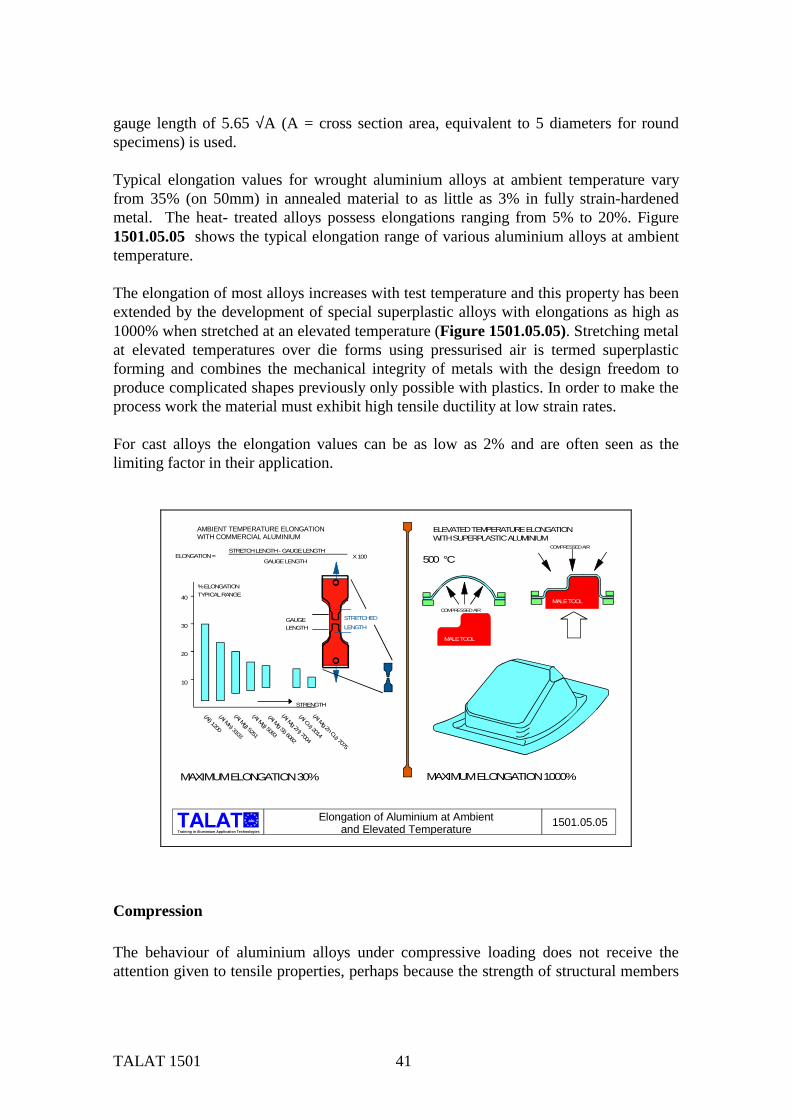
TALAT 1501 41
gauge length of 5.65 √A (A = cross section area, equivalent to 5 diameters for round specimens) is used. Typical elongation values for wrought aluminium alloys at ambient temperature vary from 35% (on 50mm) in annealed material to as little as 3% in fully strain-hardened metal. The heat- treated alloys possess elongations ranging from 5% to 20%. Figure 1501.05.05 shows the typical elongation range of various aluminium alloys at ambient temperature. The elongation of most alloys increases with test temperature and this property has been extended by the development of special superplastic alloys with elongations as high as 1000% when stretched at an elevated temperature (Figure 1501.05.05). Stretching metal at elevated temperatures over die forms using pressurised air is termed superplastic forming and combines the mechanical integrity of metals with the design freedom to produce complicated shapes previously only possible with plastics. In order to make the process work the material must exhibit high tensile ductility at low strain rates. For cast alloys the elongation values can be as low as 2% and are often seen as the limiting factor in their application.
alu
Training in Aluminium Application Technologies
MAXIMUM ELONGATION 30% MAXIMUM ELONGATION 1000%
500 °C
40
30
20
10
(Al) 1200
(Al Mn) 3103
(Al Mg) 5251
(Al Mg Si) 6082
(Al Mg Zn) 7004
(Al Cu) 2014
(Al Mg Zn Cu) 7075
STRENGTH
% ELONGATIONTYPICAL RANGE
ELONGATION =STRETCH LENGTH - GAUGE LENGTH
GAUGE LENGTHX 100
COMPRESSED AIR
MALE TOOL
GAUGELENGTH
STRETCHEDLENGTH
COMPRESSED AIR
MALE TOOL
1501.05.05Elongation of Aluminium at Ambientand Elevated Temperature
ELEVATED TEMPERATURE ELONGATIONWITH SUPERPLASTIC ALUMINIUM
(Al Mg) 5083
AMBIENT TEMPERATURE ELONGATIONWITH COMMERCIAL ALUMINIUM
Compression The behaviour of aluminium alloys under compressive loading does not receive the attention given to tensile properties, perhaps because the strength of structural members
TALAT 1501 42
is so often limited by buckling, and the actual compressive strength of the metal is not approached (Figure 1501.05.06). For most engineering purposes it is customary to use the same design stress for compressive work as for tensile. In the testing machine, an aluminium alloy will show an apparently higher strength in compression than in tension, but this can in part be attributed to the changing cross-sectional areas of the specimens, increasing in one case and decreasing in the other, while the stress is based on the original area. Cylindrical specimens of the softer aluminium alloys can be compressed to thick discs before cracking, and even then may still sustain the load. The harder alloys show a more definite failure point and pronounced cracking. A proof stress, at which there is a small measurable departure from the elastic range, is therefore usually quoted, and will be roughly equal to the corresponding tensile proof stress; in cast or forged metal it is usually slightly higher. Sheet and extruded products, however, are often straightened by stretching, an effect of which is to lower the compressive proof stress and raise the tensile proof stress by small amounts.
Bearing The ultimate bearing or crushing strength of aluminium is as difficult to define, test, or relate to tensile properties as it is with other metals. Bearing must, however, often be a criterion in the design of riveted or bolted structures, and a bearing yield stress is widely recognized; this is arbitrarily defined as the pressure (per unit effective bearing area) exerted by a pin at a round hole that will permanently deform the hole by 2% of its original diameter (Figure 1501.05.06). This stress, for most alloys, approximates in value to the ultimate tensile stress. The ultimate bearing strength of most aluminium alloys is about 1.8 times the U.T.S.

TALAT 1501 43
alu
Training in Aluminium Application Technologies
600
500
400
300
200
100
150
125
100
75
50
25
1200
5251
5083
6082
7004
2014
7075
3103
STRENGTHMPa BRINEL
HARDNESS
STRESS =P
AREA
P
P
P
P
L
=K Lrλ
λ
STRESS
SLENDERNESSRATIO
COMPRESSION CASES
d
PSTRESS = P
dt
P
Pt
BEARING
P
P
d
STRESS = 4 Pd2
SHEAR
1501.05.06
ULTIMATEBEARINGSTRENGTH
ULTIMATESHEAR
STRENGTH
BRINELHARDNESS
π
P
Compression, Shear, Bearing Strengthand Hardness for Different Aluminium Alloys
Shear In the wrought alloys the ratio of ultimate sheer stress to ultimate tensile stress varies with composition and method of fabrication from about 0.5 to 0.75. When test results are not available, a ratio of 0.55 is safe for most purposes (Figure 1501.05.06). Rivets in low and medium strength alloys, with shear strengths up to 200 MPa can be driven cold. Small rivets in stronger alloys can be driven in the soft state immediately following solution treatment and, on natural age-hardening, shear strengths up to 260 MPa will be developed.
Hardness Resistance to surface indentation is an approximate guide to the condition of an alloy, and is used as an inspection measure. Brinell (steel ball), Vickers (diamond) and Shore Scleroscope (diamond Hammer) testing machines are applied to aluminium alloys; typical Brinell values range from 20 for annealed commercially pure-metal to 175 for the strongest alloy (Figure 1501.05.06). Hardness readings should never be regarded as a quantitative index to tensile strength, as is often done with steels, for in aluminium the relation between these two properties is far from constant. The surface hardness of aluminium can be increased considerably by the process of hard anodising (500VPN) and is therefore often employed to improve the wear resistance of components.

TALAT 1501 44
Ductility We have said the elongation of a tensile test piece at fracture is a useful but not a conclusive key to the ductility of an alloy. Simple bend tests are widely used as a further indication of workability. A strip of metal with smooth rounded edges is bent through 90° or 180° by hand or mallet over a steel former of prescribed radius. By using successively tighter formers, a minimum bend radius, at which there is no cracking, can be found, and is usually quoted as a multiple of sheet thickness ″t″, for example, 1½ t. To obtain a measure of ductility a sample of sheet that is intended for deep drawing or pressing is often subjected to the Erichsen cupping test in which a hemispherical punch is forced by a hand-operated screw against one side of the sheet, stretching the metal into a dome or cup (Figure 1501.05.07). The depth of penetration at fracture gives an indication of the amenability of the metal to deep drawing processes involving stretching, though not necessarily to other pressing operations. Much of the value of this test lies in its ability to show up to two phenomena that will prevent successful drawing: a coarse grain structure produces roughness of the cup surface and perhaps an early failure through local thinning; and directionality or variation of properties in relation to the direction of rolling affects the shape of the fracture, which should be circular.
alu
Training in Aluminium Application Technologies
15
10
5
00.5 1.0 1.5 2.0 2.5 3.00
DEPT
H O
F DR
AW (
D ),
MM
SHEET THICKNESS ( t ),MM
FOR COMMERCIALLY PURE ALUMINIUM 1200
H 12
H 14
ANNEALED
H 18FULLY HARD
Dt
10 mm SPHERICALRADIUS
CLAMP
1501.05.07Erichsen Cupping Test: Effect of Sheet Thickness

TALAT 1501 45
Creep In the preceding discussions of tensile, compressive and shear properties it is implied that the stress is increased continuously and that the accompanying strains are independent of time under any given stress. If, however, a stress less than the ultimate strength is constantly maintained for a long period of time, the strain increases continuously (Figure 1501.05.08). If the stress is high enough or held long enough, the specimen eventually fails in the mode which would have occurred under continuously increasing loading. In this respect, the behaviour of aluminium is like that of other metals, and the term used for this form of failure is Creep Rupture. The creep strength of metals reduces as the operating temperature increases, again aluminium's behaviour is the same as other metals. It follows, therefore, that Creep strength cannot be expressed by a single number but must be related to operating temperatures, time and amount of deformation. Figure 1501.05.08 illustrates these relationships for an Al-Cu alloy. These data are important to the designer of a structure which is subject to stress and temperature, such as hot tarmac carrying vehicles (required life 1000's hrs), some forms of pressure vessels used in process plant (required life 100,000 hrs). It may also be necessary for predicting the life of a structure in hazard situations such as a safety critical structure surrounded by a fire (30 mins), or even a very short rupture life as maybe required in a rocket shell (2 mins). In all of these cases the time to failure at a given stress level and temperature is the design criterion, and the data are usually applied with a suitable safety allowance on time.
alu
Training in Aluminium Application Technologies
STRAIN,%
TIME - HOURS0 100 200 300 400 500
0.8
0.6
0.4
0.2
0
200 °C
175 °C
150 °C
AB
C
D
CURVES FOR ANAlCu ALLOYSTRESSED AT 110 MPa
FAILURE
1501.05.08Creep Curves for an Aluminium-Copper
Alloy Stressed at 110 MPa

TALAT 1501 46
The information available to the designer is generally the result of tests on tensile specimens subjected to constant stress at a carefully controlled temperature. By loading a number of specimens at different stress levels and constant temperature, or at different temperatures and a constant stress, perhaps for some thousands of hours, a family of curves can be obtained of the form shown in the graph Figure 1501.05.08. In each of these curves, deformation increases in four stages: first elastically, on loading (O to A on the top curve); secondly (A to B), at a decreasing rate; thirdly (B to C), at an almost constant rate, which may be negligibly small at low stresses and temperatures; and lastly (C to D), at an increasing rate which leads to failure. In this example, only the top curve has entered the final stage. The graph indicates the ways open to the designer to interpret the data. One route is to limit the total creep at a given temperature to say 0.1% in 10,000 hrs resulting in an allowable working stress. Another is to limit the working stress to a level at which the final stage of the creep curve will not be entered during the intended life of the product, and at which the total deformation at the end of this time will be within acceptable limits. Either of these methods can be applied to proposed applications. The time taken to produce creep data can be very protracted and it is usually considered impractical to continue creep and creep rupture tests beyond a few thousand hours. However, designers of pressure vessels require data that will indicate rupture at 100,000 hrs and it is therefore necessary to extrapolate the available data. Several methods have been devised for making such extrapolations, notably those by Larson and Miller, White, Clark and Wilson, Manson and Haferd and Orr, Sherby and Dorn.
Properties at Elevated Temperatures The strength of aluminium alloys decreases with the increase in temperature excluding the effects of age-hardening within narrow temperature ranges for various holding periods. The time of exposure is important in the case of cold worked or heat-treated alloys (Figure 1501.05.09) but has little or no effect on the properties of annealed alloys. The heating time at test temperature is often quoted as 10,000 hrs, but with the time-temperature dependence of strength it may be necessary for other exposure times to be considered. Shear, compression, bearing and fatigue strengths vary with temperature in much the same way as tensile strength; ratios of these strengths to tensile strength may be taken as constant.

TALAT 1501 47
alu
Training in Aluminium Application Technologies
alu
140
120
100
80
60
40
20
0-400 -200 0 200 400 600%
of R
OO
M T
EMPE
RAT
UR
E TE
NSI
LE S
TREN
GTH
TEMPERATURE in °C
10,000 hr
1,000 hr
100 hr
10 hr
1/2 hr
Tensile Strength of 2014-T6 at Test Temperatures 1501.05.09
The reduction in strength caused by exposure to elevated temperatures can only be regained by heat treatment or cold work or a combination of these processes which is usually impractical in the case of fabricated items. The tensile strength of an AlCu4MgSi alloy, tested at room temperature after exposure at elevated temperature, is shown in Figure 1501.05.10. After either short term exposure at high temperature or long term exposure at medium temperature the material approaches a super soft annealed condition and the lower limit strength becomes constant.
alu
Training in Aluminium Application Technologies
% of ROOM TEMPERATURE TENSILE STRENGTH
TEMPERATURE °C
10,000 hr
1,000 hr
100 hr
10 hr
1/2 hr
110
100
90
80
70
60
50
40
3050 100 150 200 250 300 350 400
Tensile Strength of 2014-T6 Tested at Room Temperature after Exposure at Elevated Temperature 1501.05.10
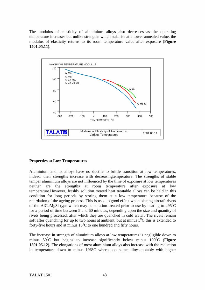
TALAT 1501 48
The modulus of elasticity of aluminium alloys also decreases as the operating temperature increases but unlike strengths which stabilise at a lower annealed value, the modulus of elasticity returns to its room temperature value after exposure (Figure 1501.05.11).
alu
Training in Aluminium Application Technologies1501.05.11
% of ROOM TEMPERATURE MODULUS
TEMPERATURE °C
120
100
80
60
40-300 -200 -100 0 100 200 300 400 500
Al Mn,Al Mg, Al Zn Mg, Al Zn Cu Mg
Al Cu
Al Mg Si
Modulus of Elasticity of Aluminium atVarious Temperatures
Properties at Low Temperatures Aluminium and its alloys have no ductile to brittle transition at low temperatures, indeed, their strengths increase with decreasingtemperature. The strengths of stable temper aluminium alloys are not influenced by the time of exposure at low temperatures neither are the strengths at room temperature after exposure at low temperature.However, freshly solution treated heat treatable alloys can be held in this condition for long periods by storing them at a low temperature because of the retardation of the ageing process. This is used to good effect when placing aircraft rivets of the AlCuMgSi type which may be solution treated prior to use by heating to 4950C for a period of time between 5 and 60 minutes, depending upon the size and quantity of rivets being processed, after which they are quenched in cold water. The rivets remain soft after quenching for up to two hours at ambient, but at minus 50C this is extended to forty-five hours and at minus 150C to one hundred and fifty hours. The increase in strength of aluminium alloys at low temperatures is negligible down to minus 500C but begins to increase significantly below minus 1000C (Figure 1501.05.12). The elongations of most aluminium alloys also increase with the reduction in temperature down to minus 196°C whereupon some alloys notably with higher
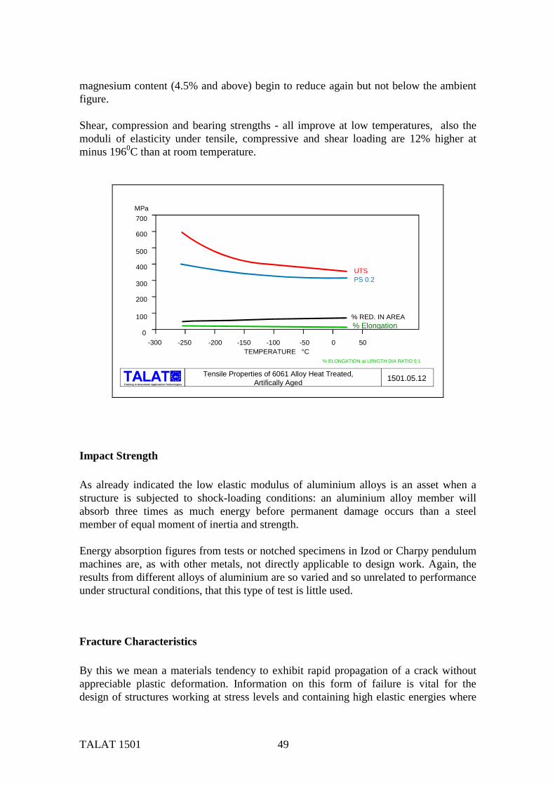
TALAT 1501 49
magnesium content (4.5% and above) begin to reduce again but not below the ambient figure. Shear, compression and bearing strengths - all improve at low temperatures, also the moduli of elasticity under tensile, compressive and shear loading are 12% higher at minus 1960C than at room temperature.
alu
Training in Aluminium Application Technologies
MPa
TEMPERATURE °C
700
600
500
400
300
200
100
0-300 -250 -200 -150 -100 -50 0 50
UTSPS 0.2
% RED. IN AREA
% ELONGATION at LENGTH DIA RATIO 5:1
Tensile Properties of 6061 Alloy Heat Treated,Artifically Aged 1501.05.12
% Elongation
Impact Strength As already indicated the low elastic modulus of aluminium alloys is an asset when a structure is subjected to shock-loading conditions: an aluminium alloy member will absorb three times as much energy before permanent damage occurs than a steel member of equal moment of inertia and strength. Energy absorption figures from tests or notched specimens in Izod or Charpy pendulum machines are, as with other metals, not directly applicable to design work. Again, the results from different alloys of aluminium are so varied and so unrelated to performance under structural conditions, that this type of test is little used.
Fracture Characteristics By this we mean a materials tendency to exhibit rapid propagation of a crack without appreciable plastic deformation. Information on this form of failure is vital for the design of structures working at stress levels and containing high elastic energies where
TALAT 1501 50
sudden failure would be catastrophic. Elongation and reduction of area from tensile tests and the ratio of yield to tensile strength, both give indications of fracture characteristics, but for the engineer these indications are seldom sufficient to be used alone as a basis for design. Charpy and Izod notched bar impact tests have been widely employed to determine the transition temperatures for ferritic steels, i.e. temperatures at which the alloys begin to exhibit brittle fracture characteristics, but these tests are generally unsuitable for aluminium and its alloys because the latter do not exhibit a transition temperature. Also notched bar impact test values for aluminium alloys are almost constant from ambient down to temperatures of minus 2680C; in addition most wrought alloys are so tough the test bars do not fracture. Therefore no useful data are obtained. To overcome this problem an adaption of the Navy tear test, originally developed by Noah Kahn to investigate the sudden failures of welded steel ships, is often employed to assess a fracture rating factor for aluminium and its alloys. In this test the energies required to initiate and propagate a crack in a specially prepared test piece (Figure 1501.05.13) are obtained by calculating the appropriate areas under the load extension curve. The energy required to propagate a crack in the tear test divided by the net cross sectional area of the specimen is referred to as the "unit propagation energy". It provides a measure of tear resistance and, indirectly, a measure of fracture toughness. The unit propagation energy obtained from the test can be related directly to the strain energy release rate for alloys that conform to the fracture mechanics theory, thereby providing a realistic measure of the resistance to rapid crack propagation. Test procedures have also been developed which relate the fracture strength of a material to a flaw or crack size or specific design detail, thereby providing a measure of "fracture toughness". Fracture toughness can be described as the resistance of a material to unstable crack propagation at elastic stresses, or to low ductility fracture of any kind. Testing for fracture toughness requires the initiation of a crack of known length in a specially prepared test piece either by fatigue loading but usually by cutting a very thin slot followed by loading in the same manner as the Navy tear test (Figure 1501.05.13),. A relationship between the stress intensity factor K, uniform gross tensile stress σa, and the length of the crack 2a is given by K = σa 2πa . The stress intensity factor K (at the onset of unstable crack propagation) decreases with the increase in metal thickness and approaches a constant minimum value which is identified as KIc the "critical elastic stress intensity factor".or the plain strain fracture toughness. KIc is analogous to yield stress since it is the minimum stress intensity at which failure can start at a given temperature and at full thickness for plain strain conditions. The fracture toughness route is not suitable for highly ductile alloys since they do not exhibit rapid crack propagation under elastic conditions. The test is therefore usually confined to the high strength heat treatable alloys.
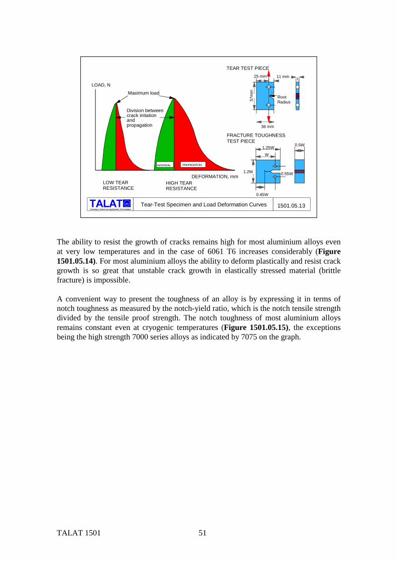
TALAT 1501 51
alu
Training in Aluminium Application Technologies
Maximum load
INITATION PROPAGATION
LOAD, N
DEFORMATION, mm
57m
m
25 mm 11 mm
36 mm
RootRadius
t
TEAR TEST PIECE
W
1.25W
1.2W
0.45W
0.55W
0.5W
FRACTURE TOUGHNESS TEST PIECE
Tear-Test Specimen and Load Deformation Curves 1501.05.13
HIGH TEARRESISTANCE
LOW TEARRESISTANCE
Division betweencrack initationandpropagation
The ability to resist the growth of cracks remains high for most aluminium alloys even at very low temperatures and in the case of 6061 T6 increases considerably (Figure 1501.05.14). For most aluminium alloys the ability to deform plastically and resist crack growth is so great that unstable crack growth in elastically stressed material (brittle fracture) is impossible. A convenient way to present the toughness of an alloy is by expressing it in terms of notch toughness as measured by the notch-yield ratio, which is the notch tensile strength divided by the tensile proof strength. The notch toughness of most aluminium alloys remains constant even at cryogenic temperatures (Figure 1501.05.15), the exceptions being the high strength 7000 series alloys as indicated by 7075 on the graph.

TALAT 1501 52
alu
Training in Aluminium Application Technologies
DATA FROM TEAR TESTS ON 0.063 IN. SHEET IN THE TRANSVERSE DIRECTION
-250 -200 -150 -100 -50 0 500
0.1
0.2
0.3
0.4
TEMPERATURE °C
UNIT PROPOGATION ENERGY mm-N/mm² or mm-Mpa
Alloy 6061 T6
Alloy 2219 T81 Alloy 5454 H 34
Alloy 2014 T6
Alloy 5083 H 113
Alloy 7075-T73
1501.05.14Unit Propagation Energies ofAluminium Alloys at Various Temperatures
alu
Training in Aluminium Application Technologies
-250 00
0.5
1
1.5
2
2.5
TEMPERATURE °C
NOTCH-YIELD RATIO (Notch Tensile Strength / Yield Stress)
CYLINDRICAL SPECIMENSNOTCH TIP RADIUS > 0.025 mmK > 14
5454-0
5083-H321
2014-T651
7075-T651
t
-200 -150 -100 -50 50 100
1501.05.15Toughness Properties of Aluminium Alloysat Low Temperatures
Fatigue (see also TALAT Lectures 2400) In common with other metals aluminium will fracture when subjected to variable or repeated loads at stress levels considerably lower than it would be the case with static loads. This type of failure which consists of the formation of cracks under the action of the fluctuating loads is known as fatigue. The fluctuating loads in practice could be caused by live loads, vibration or repeated temperature changes. The direction in which

TALAT 1501 53
the fatigue crack propagates is always perpendicular to the line of action of the stresses causing the crack. As the crack progresses the stress on the residual cross section increases so that there is a corresponding increase in the rate of crack propagation. Ultimately a stage is reached when the remaining area is insufficient to support the applied load and final rupture occurs. Fatigue cracks may be very difficult to detect since unlike tensile failures there is no visible surface contraction at the point of failure. When assessing fatigue three basic factors need to be known: 1. Number of stress cycles.
2. A definition of the stress cycle.
3. Surface finish or contour shape of the component.
The number of stress cycles is usually known or can be established by the designer for a given application. When defining a stress cycle there are four basic parameters; 1. The minimum stress Smin
2. The maximum stress Smax
3. The mean stress Sm = (Smin + Smax)/2
4. The stress range Sr = Smax - Smin
The stress cycle is fully defined provided that any two of these four quantities are known. Figure 1501.05.16 shows these factors relating to typical stress cycle patterns. Machines have been developed to apply these various types of loading rapidly and easily. A simple and well known example is the Wöhler machine, in which a cylindrical specimen is arranged as a beam or a cantilever under a steady load. Rotation of the specimen subjects it to sinusoidal alternating loading cycles. The AMSLER test machine has been developed to provide high speed tensile and compression loading of specimens to a specified wave form. The effect of the mean stress or superimposed stress on the stress cycle is shown in Figure 1501.05.17. As can be seen an imposed tensile stress reduces the number of cycles to cause failure while an imposed compressive stress increases the cycles.

TALAT 1501 54
alu
Training in Aluminium Application Technologies
W
CYCLECOUNTER
MOTOR FLEXIBLEBEARINGMAIN
COUPLINGSPECIMEN
CANTILEVERBEARING
ROTATING CANTILEVERFATIGUE TESTING MACHINE
F MAX
F MIN 1 STRESS
MEAN STRESS= ZERO
+
-
TIME
CYCLESTRESS PATTERN AT A POINT ON OUTER SURFACEOF ROTATING BAR
SIMPLE FATIGUE
VARIABLE TENSILE MACHINE
1 STRESS CYCLE
STRESS
TIME
LOAD CURVE SHAPE
SURFACE EFFECTNO EFFECT ON FATIGUE STRENGTH LARGE EFFECT ON FATIGUE STRENGTH
1501.05.16Basic Factors in Fatigue Testing
alu
Training in Aluminium Application Technologies
154
77
CYCLESto FAILURE
f minf max
105
1.1 x 10⁵
2 x 10⁵
6 x 10⁵
8 x 10⁵ 2 x 10 6 10
+ 0.25+ 0.5 0 - 0.125 - 0.25 - 0.5 - 1.0
STRESS
MEAN
F Max
F Min
t/5 maxt
MPa
ALLOYS 5251. 5083. 6082. ( BASED ON BS CP118 DATA ) CLASS 3 MEMBER
+ 38.5
- 38.5
8
STRESS
RANGE
1501.05.17The Effect of Mean Stress on Fatigue Lifeof Welded Aluminium Alloys
Unlike creep testing, fatigue testing can be speeded up; the results are not prejudiced until frequencies of the order of 500 Hz are approached. This enables many millions of cycles to be applied in a practical time. Loads applied at resonant frequency, mechanically or electrically excited can often be used to save power. The usual procedure in fatigue testing is to test a number of specimens at different stress levels. By plotting, in each case, the stress to cause failure, a stress/number (S/N) curve is obtained of the type shown in Figure 1501.05.18. It will be seen that the S/N curve for steel flattens out eventually, implying that there is a level of stress below which the
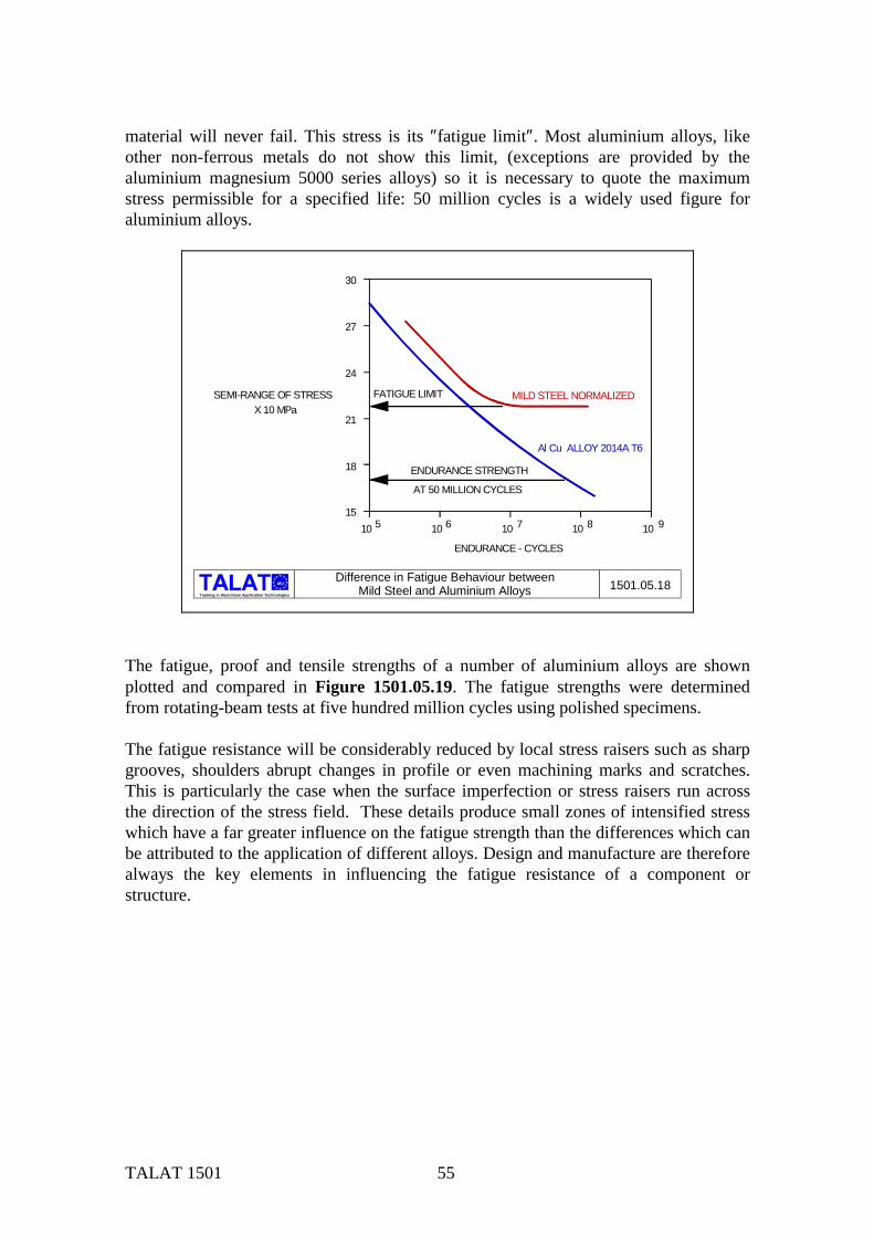
TALAT 1501 55
material will never fail. This stress is its ″fatigue limit″. Most aluminium alloys, like other non-ferrous metals do not show this limit, (exceptions are provided by the aluminium magnesium 5000 series alloys) so it is necessary to quote the maximum stress permissible for a specified life: 50 million cycles is a widely used figure for aluminium alloys.
alu
Training in Aluminium Application Technologies
SEMI-RANGE OF STRESSX 10 MPa
ENDURANCE - CYCLES
10 10 10 10 105 6 7 8 9
30
27
24
21
18
15
MILD STEEL NORMALIZED
Al Cu ALLOY 2014A T6
FATIGUE LIMIT
ENDURANCE STRENGTH
AT 50 MILLION CYCLES
1501.05.18Difference in Fatigue Behaviour betweenMild Steel and Aluminium Alloys
The fatigue, proof and tensile strengths of a number of aluminium alloys are shown plotted and compared in Figure 1501.05.19. The fatigue strengths were determined from rotating-beam tests at five hundred million cycles using polished specimens. The fatigue resistance will be considerably reduced by local stress raisers such as sharp grooves, shoulders abrupt changes in profile or even machining marks and scratches. This is particularly the case when the surface imperfection or stress raisers run across the direction of the stress field. These details produce small zones of intensified stress which have a far greater influence on the fatigue strength than the differences which can be attributed to the application of different alloys. Design and manufacture are therefore always the key elements in influencing the fatigue resistance of a component or structure.

TALAT 1501 56
alu
Training in Aluminium Application Technologies
Strength (MPa)
Alloy and Temper
0 136 272 408 544
Fatigue Strength500,000,000 cyclesPolished specimens
7075
2014
7004
6061
70045083606130035454
3003
UltimateProof
T6
T6
T6A
T6
T4AH11T4H140
0
-
-
-
-
-----
-
Fatigue
1501.05.19Fatigue, Proof and Ultimate Tensile Strengths
of some Wrought Aluminium Alloys
These last statements are particularly true when considering welded fabrications and they hold true both for aluminium and steel. There are three major factors responsible for the low fatigue strength of welded joints.
Profile: A weld produces a surface discontinuity, which creates stress concentrations. It follows therefore that a fillet weld will have a lower fatigue strength than say a flush ground butt. The orientation of the surface discontinuity is also important (as illustrated in Figure 1501.05.16). Defects: Welds often contain surface ripples or crack-like discontinuities which act as fatigue crack initiators. Residual stress: Welded joints contain high levels of tensile residual stress (Figure 1501.05.20), which act like the superimposed stress shown in Figure 1501.05.17. These are caused by the thermal shrinkage inherent in the process.
The presence of residual welding stresses and the possibility of stress raisers introduced to the parent material during its working life by the accumulation of cuts and scratches, has prompted recent actions to rationalize the application of fatigue data in commercial structures. This latest thinking is applied to the S/N curves published in The British Standard for the structural use of aluminium (BS 8118, Part1:1991). These curves assume that a maximum stress of yield tension is always present in the joint. From a practical standpoint this therefore assumes that the life of a joint subjected to a stress fluctuation between -30 MPa and + 40 MPa is not different from that of the same joint subjected to a stress fluctuating between +30 MPa and +100 MPa. The curves only force

TALAT 1501 57
the designer to assess the stress range and ignore any further influence of mean stress; this follows the same format as that used in the UK structural steel bridge design code BS5400. The aluminium values for the S/N curves in BS 8118 are nominally BS5400 steel divided by 3. Other countries are applying the basic fatigue data in different ways in practice, for instance Canada still uses the concept of applied mean stress. Therefore the interpretation of theory into practice will continue to be a point of inconsistency for the foreseeable future. The high levels of tensile residual stress at the welds can be reduced by hammer or shot peening which has the effect of inducing beneficial compressive stresses and thereby improving the fatigue life. The fatigue life of the weld can also be improved by removing weld surface ripples by grinding or water jet erosion.
alu
Training in Aluminium Application Technologies
COLD
COLD
COLD CUT
CUT
HOT
COLD
COLD
RESIDUALSTRESSES
+
--+-
-
LONGITUDINAL TRANSVERSE
1501.05.20Residual Stresses Around a Butt Weld

TALAT 1501 58
1501.06 Literature/References
Aluminium-Taschenbuch Edited by Aluminium-Zentrale. XXVI/1094 pages, 699 figures, 342 tables,
14.Edition, 1983/1988, ISBN 3-87017-169-3. Metals Handbook American Society for Metals, 2nd edition, 1990 E.Hatch (Editor): Aluminium - Properties and Physical Metallurgy American Society for Metals, Metals Park, Ohio, 1984, ISBN 0-87179-176-6 ALUSELECT - The European Engineering Properity Database for Wrought
Aluminium and Aluminium Alloys, 2 diskettes.EAA, KTH 1992 Mateds: The Materials Technology Education System SkanAluminium, KTH 1990 Sandström, R.: Introduction to Materials Selection, KTH 1990 D.G. Altenpohl: Aluminum Viewed From Within - An Introduction to the
Metallurgy of Aluminum Fabrication, XII/225 pages, 190 figures, 16 tables. Aluminium-Verlag Düsseldorf, 1982, ISBN 3-87017-138-3
The Properties of Aluminum and ist Alloys. Aluminum Federation Ltd., Birmingham 1993 F. King: Aluminum and its Alloys. Ellis Harwood Series in Metals Materials. Ellis Harwood, Chichester, England
1987 Aluminum Association Inc. Registration Record of International Alloy Designations and Chemical
Composition Limits for Wrought Aluminum and Wrought Aluminum Alloys. Aluminum Association, Washington DC, May 1987 (or most recent).

TALAT 1501 59
1501.07 List of Figures Figure Nr. Figure Title (Overhead) 1501.01.01 Raw Materials and Processes for Aluminium Production 1501.01.02 Raw Materials to Produce One Tonne of Aluminium Ingot 1501.02.01 Atomic Structure of Aluminium 1501.02.02 Volume per Unit Weight 1501.02.03 Electrical Properties of Aluminium Compared With Other Metals 1501.02.04 Magnetic Susceptibility of Al-Cu Alloys 1501.02.05 Thermal Conductivity of Aluminium Compared with Other Metals 1501.02.06 Reflectivity and Emissivity of Aluminium with Various Surface Treatments 1501.02.07 Comparison of Reflectivity of Various Metals 1501.02.08 Pitting Corrosion Behaviour of 3103 Mill Finish Aluminium Sheet 1501.02.09 Principles of Anodizing 1501.02.10 Bi-Metallic Corrosion at Junction of Aluminium with Other Metals 1501.02.11 Thermal Expansion Matching Using MMCs 1501.02.12 Sliding and Rigid Joints of Aluminium/Steel Structures 1501.02.13 Brazing of Aluminium Using Clad Sheet 1501.03.01 Aluminium Alloy Designation System 1501.03.02 The Effect of Alloying Elements on Tensile Strength, Hardness, Impact
Sensitivity and Ductility 1501.03.03 The Effect of Alloying Elements on Weldability and Anodizing 1501.03.04 The Effects of Alloying Elements on Corrosion Resistance and Fatigue
Strength 1501.03.05 The Effect of Alloying Elements on Density and Young’s Modulus 1501.04.01 Work Hardening of Aluminium 1501.04.02 Metallurgy of Precipitation Hardening (e.g.Al-Cu System) 1501.04.03 Ageing Curves for Aluminium Alloy 6082 1501.04.04 A Selection of Common Temper Designation for Aluminium Alloys 1501.05.01 Stress-Strain Curves of Aluminium in Comparison with Various Metals and
Alloys 1501.05.02 Density-Related Strength of Aluminium in Comparison with Various Metals
and Alloys 1501.05.03 Plastic Yield Behaviour of Aluminium and Mild Steel 1501.05.04 Stiffness-Weight Relationship as Design Criteria
Example: Trailer Chassis 1501.05.05 Elongation of Aluminium at Ambient and Elevated Temperatures

TALAT 1501 60
Figure Nr. Figure Title (Overhead) 1501.05.06 Compression, Shear, Bearing Strength and Hardness for Different Aluminium
Alloys 1501.05.07 Erichsen Cupping Test: Effect of Sheet Thickness 1501.05.08 Creep Curves for an Aluminium-Copper Alloy Stressed at 110 MPa 1501.05.09 Tensile Strength of 2014-T6 at Test Temperatures 1501.05.10 Tensile Strength of 2014-T6 Tested at Room Temperature after Exposure at
Elevated Temperature 1501.05.11 Modulus of Elasticity of Aluminium at Various Temperatures 1501.05.12 Tensile Properties of 6061 Alloy Heat Treated, Artificially Aged 1501.05.13 Tear-Test Specimen and Load-Deformation Curves 1501.05.14 Unit Propagation Energies of Aluminium Alloys at Various Temperatures. 1501.05.15 Toughness Properties of Aluminium Alloys at Low Temperatures 1501.05.16 Basic Factors in Fatigue Testing 1501.05.17 The Effect of Mean Stress on Fatigue Life of Welded Aluminium Alloys 1501.05.18 Difference in Fatigue Behaviour between Mild Steel and Aluminium Alloys 1501.05.19 Fatigue, Proof and Ultimate Tensile Strengths of some Wrought Aluminium
Alloys 1501.05.20 Residual Stresses around a Butt Weld