Embed Size (px)
Citation preview
AlphaPilot MFM
Operation Manual
www.alphatronmarine.com
2 | Introduction
Contents
I. Preface ............................................................................................................................................. 5
Revision History ................................................................................................................................... 6
Glossary ............................................................................................................................................... 7
Abbreviations ................................................................................................................................... 7
Definitions ........................................................................................................................................ 8
II. Safety Information ......................................................................................................................... 12
III. Warranty........................................................................................................................................ 14
IV. About the manual .......................................................................................................................... 15
Intended readers ............................................................................................................................... 15
Manual overview ............................................................................................................................... 15
Related documents ............................................................................................................................ 15
1 Introduction ................................................................................................................................... 16
2 AlphaPilot MFM control unit ......................................................................................................... 17
3 Operating modes ........................................................................................................................... 22
3.1 Introduction ........................................................................................................................... 22
3.2 Standby (S) mode .................................................................................................................. 24
3.3 Follow-Up (F) mode ............................................................................................................... 24
3.4 Auto (A) control mode ........................................................................................................... 25
3.4.1 Introduction ................................................................................................................... 25
3.4.2 Enable Auto (A) control mode ....................................................................................... 26
3.4.3 Steering in Auto (A) control mode ................................................................................ 26
3.5 Low Speed Heading Control mode ........................................................................................ 27
3.5.1 Introduction ................................................................................................................... 27
3.5.2 Enable Low Speed Heading Control mode .................................................................... 28
3.5.3 Steering in Low Speed Heading Control mode .............................................................. 29
3.6 Dodge (D) mode .................................................................................................................... 30
3.6.1 Introduction ................................................................................................................... 30
3.6.2 Enable Dodge (D) control mode .................................................................................... 30
3.6.3 Steering in Dodge (D) control mode .............................................................................. 30
3.7 Override (O) control mode .................................................................................................... 31
3.7.1 Introduction ................................................................................................................... 31
3.7.2 Enable Override (O) control mode ................................................................................ 32
3 | Introduction
3.7.3 Steering in Override (O) control mode .......................................................................... 32
3.8 Track (T) control modes ......................................................................................................... 33
3.8.1 Introduction ................................................................................................................... 33
3.8.2 Track (T) control mode, TCS category A, B .................................................................... 34
3.8.3 Track (TN or TI) control mode, TCS category C .............................................................. 38
3.9 Rate of Turn (R) control mode ............................................................................................... 40
3.9.1 Introduction ................................................................................................................... 40
3.9.2 Enable Rate of Turn (R) mode ....................................................................................... 41
3.9.3 Steering in Rate of Turn (R) mode ................................................................................. 41
3.9.4 Change parameters ....................................................................................................... 41
3.10 CTS pilot (C) control mode..................................................................................................... 42
3.10.1 Introduction ................................................................................................................... 42
3.10.2 Enable CTS pilot (C) control mode ................................................................................. 43
3.10.3 Steering in CTS pilot (C) control mode .......................................................................... 43
3.10.4 Change the resolution ................................................................................................... 43
3.10.5 Change parameters ....................................................................................................... 43
3.11 Wind vane (V) control mode ................................................................................................. 44
3.11.1 Introduction ................................................................................................................... 44
3.11.2 Enable Wind vane (V) control mode ............................................................................. 45
3.11.3 Steering in Wind vane (V) control mode ....................................................................... 45
3.11.4 Change parameters ....................................................................................................... 45
4 Controls and functions .................................................................................................................. 47
4.1 Reset and turn off .................................................................................................................. 47
4.2 Enabling control ..................................................................................................................... 48
4.2.1 Control allowed/not allowed ........................................................................................ 49
4.2.2 Control handover........................................................................................................... 49
4.3 Alert handling ........................................................................................................................ 50
4.4 Dimming ................................................................................................................................ 50
4.5 Alarm test .............................................................................................................................. 50
5 Menus ............................................................................................................................................ 51
5.1 Menu ‘Parameters’ ................................................................................................................ 51
5.2 Menu ‘Alarm Settings’ ........................................................................................................... 53
5.3 Menu ‘Advanced’ .................................................................................................................. 54
4 | Introduction
5.3.1 Submenu ‘Set Devices’ .................................................................................................. 54
5.3.2 Submenu ‘Panel Settings’ .............................................................................................. 57
5.4 Menu ‘Installation’ ................................................................................................................ 58
5.5 Alert logs ................................................................................................................................ 59
6 Alarms, warnings, and cautions .................................................................................................... 60
7 Troubleshooting ............................................................................................................................ 64
Appendices ............................................................................................................................................ 65
Appendix A: Specification - AlphaPilot MFM control unit ................................................................. 65
Appendix B: Alphatron MFM Alerts .................................................................................................. 66
5 | Introduction
I. Preface The Alphatron AlphaPilot MFM system is a type approved Heading Control System (i.e. Autopilot)
with self-adjusting ‘Auto Tune’ algorithm, designed to fit vessels of any size, including high speed
crafts. It is a modern and technologically advanced digital vessel control unit that is intended to
reduce the operator’s workload, increase the vessel motion efficiency and improve operational
safety.
The AlphaPilot MFM control unit is the main control module of the AlphaPilot MFM system. It is
used for control and monitoring of autopilot operation, setting vessel heading or rudder angle,
selection of autopilot operating modes.
• Thoroughly read this operation manual before operating the equipment.
• We recommend keeping this manual nearby the equipment to ensure ready access to it.
6 | Introduction
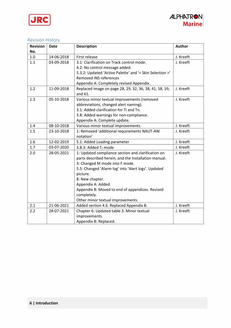
Revision History Revision No.
Date Description Author
1.0 14-06-2018 First release J. Kreeft
1.1 03-09-2018 3.1: Clarification on Track control mode. 4.2: No control message added. 5.3.2: Updated ‘Active Palette’ and ‘< Skin Selection >’ Removed INS references Appendix A: Completely revised Appendix.
J. Kreeft
1.2 11-09-2018 Replaced image on page 28, 29, 32, 36, 38, 41, 58, 59, and 61.
J. Kreeft
1.3 05-10-2018 Various minor textual improvements (removed abbreviations, changed alert naming). 3.1: Added clarification for Ti and Tn. 3.8: Added warnings for non-compliance. Appendix A: Complete update.
J. Kreeft
1.4 08-10-2018 Various minor textual improvements. J. Kreeft
1.5 23-10-2018 1: Removed ‘additional requirements NAUT-AW notation’
J. Kreeft
1.6 12-02-2019 5.1: Added Loading parameter J. Kreeft
1.7 03-07-2020 3.8.3: Added TI mode J. Kreeft
2.0 28-05-2021 1: Updated compliance section and clarification on parts described herein, and the Installation manual. 3: Changed M mode into F mode. 5.5: Changed ‘Alarm log’ into ‘Alert logs’. Updated picture. 8: New chapter. Appendix A: Added. Appendix B: Moved to end of appendices. Revised completely. Other minor textual improvements
J. Kreeft
2.1 21-06-2021 Added section 4.6. Replaced Appendix B. J. Kreeft
2.2 28-07-2021 Chapter 6: Updated table 3. Minor textual improvements. Appendix B: Replaced.
J. Kreeft
7 | Introduction
Glossary The glossary contains a list of abbreviations and a list of definitions.
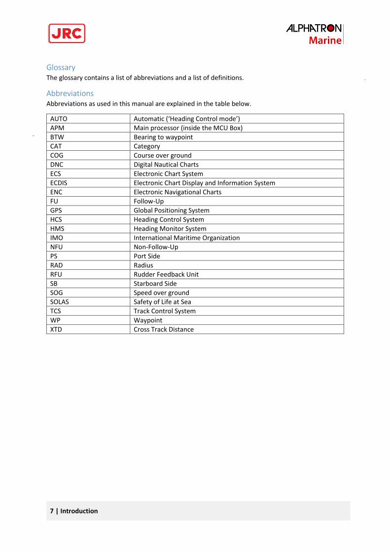
Abbreviations Abbreviations as used in this manual are explained in the table below.
AUTO Automatic (‘Heading Control mode’)
APM Main processor (inside the MCU Box)
BTW Bearing to waypoint
CAT Category
COG Course over ground
DNC Digital Nautical Charts
ECS Electronic Chart System
ECDIS Electronic Chart Display and Information System
ENC Electronic Navigational Charts
FU Follow-Up
GPS Global Positioning System
HCS Heading Control System
HMS Heading Monitor System
IMO International Maritime Organization
NFU Non-Follow-Up
PS Port Side
RAD Radius
RFU Rudder Feedback Unit
SB Starboard Side
SOG Speed over ground
SOLAS Safety of Life at Sea
TCS Track Control System
WP Waypoint
XTD Cross Track Distance
8 | Introduction
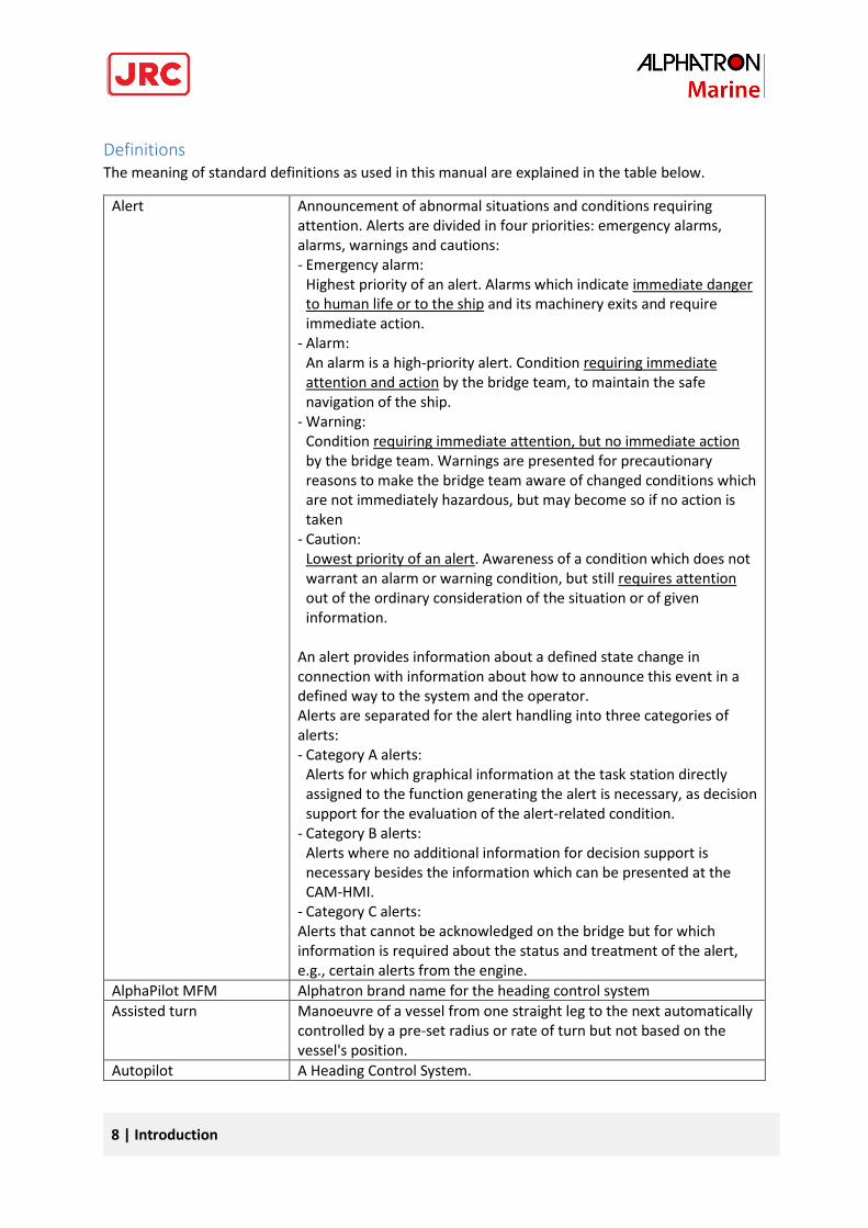
Definitions The meaning of standard definitions as used in this manual are explained in the table below.
Alert Announcement of abnormal situations and conditions requiring attention. Alerts are divided in four priorities: emergency alarms, alarms, warnings and cautions: - Emergency alarm:
Highest priority of an alert. Alarms which indicate immediate danger to human life or to the ship and its machinery exits and require immediate action.
- Alarm: An alarm is a high-priority alert. Condition requiring immediate attention and action by the bridge team, to maintain the safe navigation of the ship.
- Warning: Condition requiring immediate attention, but no immediate action by the bridge team. Warnings are presented for precautionary reasons to make the bridge team aware of changed conditions which are not immediately hazardous, but may become so if no action is taken
- Caution: Lowest priority of an alert. Awareness of a condition which does not warrant an alarm or warning condition, but still requires attention out of the ordinary consideration of the situation or of given information.
An alert provides information about a defined state change in connection with information about how to announce this event in a defined way to the system and the operator. Alerts are separated for the alert handling into three categories of alerts: - Category A alerts:
Alerts for which graphical information at the task station directly assigned to the function generating the alert is necessary, as decision support for the evaluation of the alert-related condition.
- Category B alerts: Alerts where no additional information for decision support is necessary besides the information which can be presented at the CAM-HMI.
- Category C alerts: Alerts that cannot be acknowledged on the bridge but for which information is required about the status and treatment of the alert, e.g., certain alerts from the engine.
AlphaPilot MFM Alphatron brand name for the heading control system
Assisted turn Manoeuvre of a vessel from one straight leg to the next automatically controlled by a pre-set radius or rate of turn but not based on the vessel's position.
Autopilot A Heading Control System.
9 | Introduction
COG (Course Over Ground)
COG is the actual direction of progress of a vessel, between two points, with respect to the surface of the earth. The vessel’s heading may differ from the COG because of wind, tide and currents.
Course A vessel's course is the cardinal direction along which the vessel is to be steered. It is to be distinguished from the vessel's heading, which is the compass direction in which the craft's bow is pointed.
Cross track distance Perpendicular distance of the vessel from the track including direction (negative if the vessel is left of the intended track)
Cross track error See ‘Cross track distance’
Cross-track limit Maximum cross track distance before an alert is activated.
Curved track Non-straight track between two straight legs.
ECDIS (Electronic Chart Display and Information System)
A geographic information system used for nautical navigation that complies with IMO regulations as an alternative to paper nautical charts. An ECDIS displays the information from ENC or DNC and integrates position information from position, heading and speed through water reference systems and optionally other navigational sensors. Other sensors which could interface with an ECDIS are radar, Navtex, Automatic Identification Systems (AIS), and depth sounders.
Electronic Navigational Charts
An official database created by a national hydrographic office for use with an ECDIS.
Heading The horizontal direction in which a vessel points or heads at any instant, expressed in angular units from a reference direction, usually from 000° at the reference direction clockwise through 360°.
Heading control Control of the vessel's heading.
HCS (Heading Control System)
A system which enables a vessel to keep a pre-set heading with minimum operation of the vessel's steering gear, within limits related to the vessel's manoeuvrability in conjunction with their sources of heading information. The HCS may work together with a TCS. A turn rate control or a turning-radius control for performing turns may be provided. The term HCS differentiates the automatic pilot (autopilot) from a system designed to keep a vessel on a pre-determined track throughout its passage, which is called TCS.
Heading Monitor System This system monitors the actual heading sensor by an independent second source.
Helm A wheel or tiller by which a vessel is steered.
IEC A non-profit, non-governmental international standards organization that prepares and publishes International Standards for all electrical, electronic and related technologies.
Indication Visual display of any message to the user which may be accompanied by a low intensity acoustic signal to gain attention.
Latitude and Longitude The units that represent the coordinates at geographic coordinate system.
LOG Speed data from Water Speed Log
Leg Line between two waypoints defining the track.
10 | Introduction
Main conning position Place on the bridge with a commanding view providing the necessary information and equipment for the conning officer to carry out his functions.
Main steering gear The machinery, rudder actuators, steering gear power units, if any, and ancillary equipment and the means of applying torque to the rudder stock (e.g. tiller or quadrant) necessary for effecting movement of the rudder for steering the vessel under normal service conditions.
Magnetic compass The Earth has a magnetic field which is approximately aligned with its axis of rotation. A magnetic compass is a device that uses this field to determine the cardinal directions.
Manual (steering) mode Method of controlling steering gear manually is contrast with automatic steering control mode (course control mode). Both Follow-Up and Non-Follow-Up modes may be considered as manual steering mode.
Override function An intentional fast change-over from automatic to temporary manual control.
Radius of turn Radius of a curved track
Rate-Of-Turn The speed (or rate) at which a vessel is turning at, or can turn at, measured in degrees per minute.
Relative bearing The direction of a target from own vessel expressed as an angular displacement from own vessel's heading.
Relative course The direction of motion of a target relative to own vessel's position expressed as an angular displacement from north. It is deduced from several measurements of target range and bearing on own vessel's radar.
Relative speed The speed of a target relative to own vessel's position. It is deduced from several measurements of target range and bearing on own vessel's radar.
Rudder Feedback Unit The Rudder Feedback Unit can be used in a rudder angle indicator system and as a part of the control loop in a steering control system.
SOLAS (Safety of Life at Sea)
An international maritime treaty which requires signatory flag states to ensure that vessels flagged by them comply with minimum safety standards in construction, equipment, and operation.
Speed The absolute value of velocity. May either be the vessel's speed through the water, or the speed made good over the ground.
SOG (Speed over ground) The speed of the vessel relative to the surface of the earth.
Steering gear The equipment provided on vessels to turn the vessel.
Steering mode selector A switch provided for the selection of manual steering modes and automatic steering devices.
Tiller A device that is used to turn the rudder, which then steers the boat.
Track Path to be followed over ground.
Track control Control of the vessel's movement along a track, where corrections made by the controller to compensate for wind, drift and other influences, are based on the cross-track error and not only on the bearing to the destination waypoint.
11 | Introduction
TCS (Track Control System)
System designed to keep a vessel on a pre-determined track throughout its passage. Track Control systems must be interfaced with an electronic position fixing system. SOLAS Regulation 19, 2.8.2 requires Heading Control or Track Control Systems to be fitted to all vessels of 10000 GT and upward. There is no requirement to fit a Track Control system to any class of vessel. Track Control Systems include the functional capabilities of Heading Control systems.
Waypoint An intermediate point or place on a route or line of travel, a stopping point or point at which course is changed.
12 | Introduction
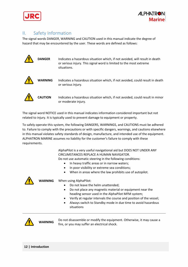
II. Safety Information The signal words DANGER, WARNING and CAUTION used in this manual indicate the degree of
hazard that may be encountered by the user. These words are defined as follows:
DANGER
Indicates a hazardous situation which, if not avoided, will result in death or serious injury. This signal word is limited to the most extreme situations.
WARNING
Indicates a hazardous situation which, if not avoided, could result in death or serious injury.
CAUTION
Indicates a hazardous situation which, if not avoided, could result in minor or moderate injury.
The signal word NOTICE used in this manual indicates information considered important but not
related to injury. It is typically used to prevent damage to equipment or property.
To safely operate this system, the following DANGERS, WARNINGS, and CAUTIONS must be adhered
to. Failure to comply with the precautions or with specific dangers, warnings, and cautions elsewhere
in this manual violates safety standards of design, manufacture, and intended use of the equipment.
ALPHATRON MARINE assumes no liability for the customer's failure to comply with these
requirements.
WARNING
AlphaPilot is a very useful navigational aid but DOES NOT UNDER ANY CIRCUMSTANCES REPLACE A HUMAN NAVIGATOR. Do not use automatic steering in the following conditions:
• In heavy traffic areas or in narrow waters;
• In poor visibility or extreme sea conditions;
• When in areas where the law prohibits use of autopilot.
When using AlphaPilot:
• Do not leave the helm unattended;
• Do not place any magnetic material or equipment near the heading sensor used in the AlphaPilot MFM system;
• Verify at regular intervals the course and position of the vessel;
• Always switch to Standby mode in due time to avoid hazardous situations
WARNING
Do not disassemble or modify the equipment. Otherwise, it may cause a fire, or you may suffer an electrical shock.
13 | Introduction
WARNING
Immediately turn off the power and disconnect the power supply cable if the equipment is generating any smoke or odour or is overheated. Immediately inform your local service agent of the symptom to have it repaired. Prolonged equipment operation under such a condition can cause a fire or electric shock.
WARNING
Do not place a container containing liquid on the equipment. Otherwise, it may cause a fire, or you may suffer an electrical shock if knocked over.
WARNING
When unplugging the instrument, be sure to remove the cord terminal correctly. If the cord is pulled, the cord may get damaged resulting in a fire or an electrical shock.
14 | Introduction
III. Warranty To not to adversely affect the warranty, the following notices must be adhered to.
NOTICE
Operating personnel must not remove equipment covers. Only personnel trained and certified by ALPHATRON MARINE must make component replacement and internal adjustment.
NOTICE
Do not disassemble or modify the equipment. Failure to observe this instruction may cause equipment failure, and it will void the warranty.
NOTICE
Any modification to this equipment without prior written permission from ALPHATRON MARINE will void the warranty.
NOTICE
Installation of this product shall only be done by a certified installation company approved by either ALPHATRON MARINE or by an official ALPHATRON MARINE distributor. Acting otherwise will void the warranty.
NOTICE
This product contains no operator serviceable parts. Service and repair shall only be carried out by personnel trained and certified by ALPHATRON MARINE.
NOTICE
Do not place a container containing liquid on the equipment. The equipment can be damaged if knocked over.
NOTICE
When cleaning the surface, do not use any organic solvent such as thinner or benzine. Otherwise, the paint and markings on the surface may get damaged. For cleaning the surface, remove the dust and debris and wipe with a clean dry cloth.
15 | Introduction
IV. About the manual
Intended readers This manual is an operation manual for the AlphaPilot MFM system and control unit. The manual is
intended for end users.
Manual overview This manual has the following chapters:
• Introduction contains a description of the AlphaPilot MFM system.
• AlphaPilot MFM control unit contains a description of the control unit and its interface.
• Operating modes contains a description of the autopilot operating modes.
• Controls and functions contains a description of the basic functions such as dimming, control
handover, alert handling, and alarm test.
• Menus contains a description of the accessible menus and menu items.
• Alarms, warnings, and cautions contains a description of alerts displayed on the AlphaPilot
MFM control unit.
Related documents The Alphatron AlphaPilot MFM system is available in many configurations, therefore 1 or more
documents listed below may not be applicable.
• Alphatron Marine FU Tiller Operation Manual
• Alphatron Marine FU Tiller ROT Operation Manual
• Alphatron Marine FU Tiller S/I Operation Manual
• Alphatron Marine NFU Tiller Operation Manual
• Alphatron Marine Handwheel SR Operation Manual
• Alphatron Marine Handwheel TR Operation Manual
• Alphatron Marine Mode Switch 2 Pos Operation Manual
• Alphatron Marine Mode Switch 3 Pos Operation Manual
• Alphatron Marine RFU Rudder Feedback Unit MD/HD Installation and Operation Manual
Contact the Alphatron dealer for copies of the documents listed above.
16 | Introduction
1 Introduction The Alphatron AlphaPilot MFM system is a type approved heading control system with self-adjusting
‘Auto Tune’ algorithm, designed to fit vessels of any size, including high speed crafts. It is a modern
and technologically advanced digital vessel control unit that is intended to reduce the operator’s
workload, increase the vessel motion efficiency and improve operational safety.
The AlphaPilot MFM control unit is the main operator control unit of the AlphaPilot MFM system. It
is used for control and monitoring of autopilot operation, setting vessel heading or rudder angle,
selection of autopilot operating modes.
The AlphaPilot MFM control unit works in conjunction with an MCU (Main Control Unit) Box, which
connects to the steering system or to the steering gear.
Refer to the AlphaPilot MFM Installation Manual for more details about the MCU Box and other
technical information (including, but not limited to details about connectivity, data input, and data
output).
WARNING! Always switch to Standby mode in due time to avoid hazardous situations.
WARNING! AlphaPilot is a very useful navigational aid but DOES NOT UNDER ANY
CIRCUMSTANCES REPLACE A HUMAN NAVIGATOR.
Do not use automatic steering in the following conditions:
• In heavy traffic areas or in narrow waters;
• In poor visibility or extreme sea conditions;
• When in areas where the law prohibits use of autopilot.
When using AlphaPilot:
• Do not leave the helm unattended;
• Do not place any magnetic material or equipment near the heading sensor used
in the AlphaPilot MFM system;
• Verify at regular intervals the course and position of the vessel;
• Always switch to Standby mode (i.e. Mode Switch to ‘MAN’ or ‘NFU’ position) in
due time to avoid hazardous situations (ref. SOLAS-74 (Safety of Life at Sea),
chapter 5, rule 19, International Regulations for
Preventing Collisions at Sea; Navigation Rules-72, Rule 5 & etc.)
Compliance
The Alphatron AlphaPilot MFS system meets the following carriage and performance requirements:
MED/4.16 Heading Control Systems (HCS):
17 | AlphaPilot MFM control unit
- SOLAS 74 Reg. V/18 & V/19
- IMO Res.A.342(IX)
- IMO Res.A.694(17)
- IMO Res.MSC.191(79)
- IMO Res.MSC.64(67) Annex 3
- IMO Res.MSC.302(87)
MED/4.40 Heading Control System (HCS) for High Speed Craft (HSC):
- SOLAS 74 Reg. X/3
- IMO Res.MSC.36(63)-(1994 HSC Code) 13
- IMO Res.MSC.97(73)-(2000 HSC Code) 13
- IMO Res.A.694(17)
- IMO Res.A.822(19)
- IMO Res.MSC.191(79)
- IMO Res.MSC.302(87)
- IMO MSC.1/Circ.1349
‘Fail-to-safety’ principle
‘Fail-to-safety’ principle is implemented in the AlphaPilot MFM system design, i.e. any failure results
in the least critical of any possible new conditions.
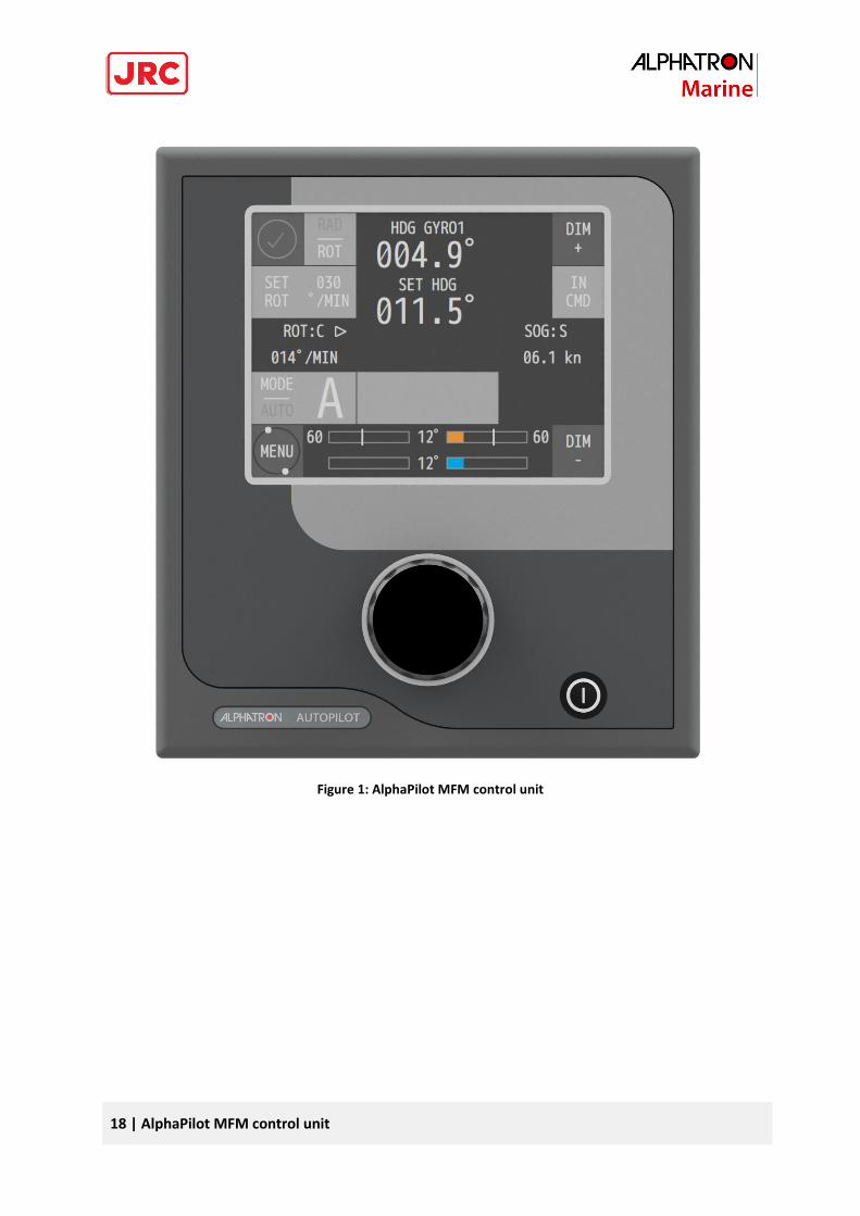
2 AlphaPilot MFM control unit The AlphaPilot MFM control unit has a touch screen display, a rotary knob, and a power button:
- The touch screen display shows information such as heading, current mode and settings, and
alerts. The touch screen display is also used to set parameters (see Figure 2 on page 19).
- The rotary knob is used for various purposes such as, changing heading, and setting
parameters.
- The power button is used to reset the AlphaPilot MFM.
18 | AlphaPilot MFM control unit
Figure 1: AlphaPilot MFM control unit
19 | AlphaPilot MFM control unit
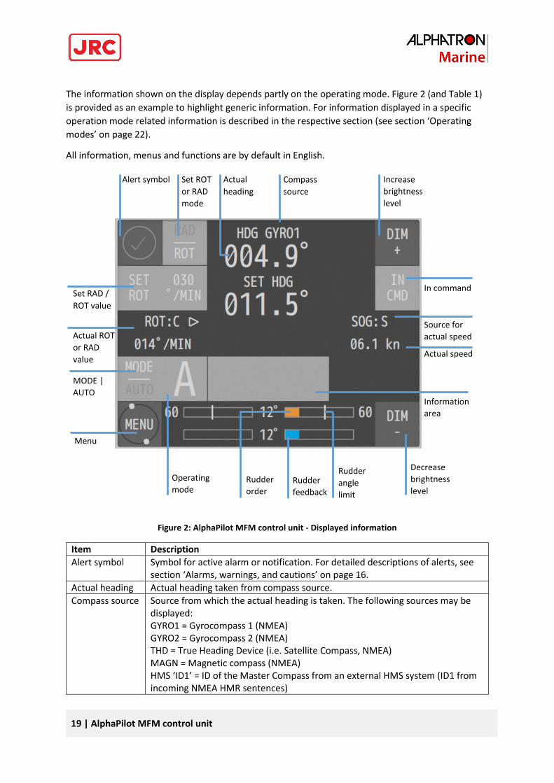
The information shown on the display depends partly on the operating mode. Figure 2 (and Table 1)
is provided as an example to highlight generic information. For information displayed in a specific
operation mode related information is described in the respective section (see section ‘Operating
modes’ on page 22).
All information, menus and functions are by default in English.
Figure 2: AlphaPilot MFM control unit - Displayed information
Item Description
Alert symbol Symbol for active alarm or notification. For detailed descriptions of alerts, see section ‘Alarms, warnings, and cautions’ on page 16.
Actual heading Actual heading taken from compass source.
Compass source Source from which the actual heading is taken. The following sources may be displayed: GYRO1 = Gyrocompass 1 (NMEA) GYRO2 = Gyrocompass 2 (NMEA) THD = True Heading Device (i.e. Satellite Compass, NMEA) MAGN = Magnetic compass (NMEA) HMS ‘ID1’ = ID of the Master Compass from an external HMS system (ID1 from incoming NMEA HMR sentences)
Actual
heading
Compass
source
Set RAD /
ROT value
Alert symbol Set ROT
or RAD
mode
Actual speed
Actual ROT
or RAD
value
MODE |
AUTO Information
area
Source for
actual speed
Operating
mode Rudder
order
Rudder
angle
limit
Decrease
brightness
level
Increase
brightness
level
In command
Menu
Rudder
feedback
20 | AlphaPilot MFM control unit
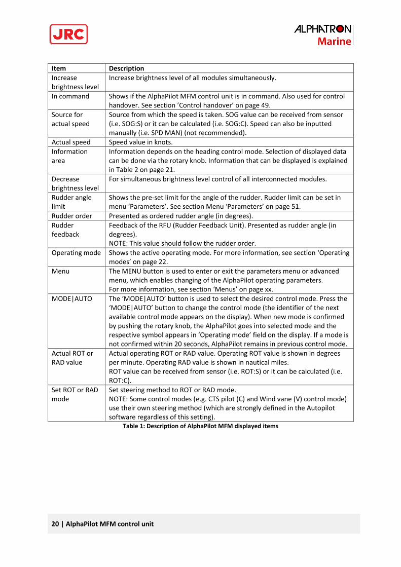
Item Description
Increase brightness level
Increase brightness level of all modules simultaneously.
In command Shows if the AlphaPilot MFM control unit is in command. Also used for control handover. See section ’Control handover’ on page 49.
Source for actual speed
Source from which the speed is taken. SOG value can be received from sensor (i.e. SOG:S) or it can be calculated (i.e. SOG:C). Speed can also be inputted manually (i.e. SPD MAN) (not recommended).
Actual speed Speed value in knots.
Information area
Information depends on the heading control mode. Selection of displayed data can be done via the rotary knob. Information that can be displayed is explained in Table 2 on page 21.
Decrease brightness level
For simultaneous brightness level control of all interconnected modules.
Rudder angle limit
Shows the pre-set limit for the angle of the rudder. Rudder limit can be set in menu ‘Parameters’. See section Menu ‘Parameters’ on page 51.
Rudder order Presented as ordered rudder angle (in degrees).
Rudder feedback
Feedback of the RFU (Rudder Feedback Unit). Presented as rudder angle (in degrees). NOTE: This value should follow the rudder order.
Operating mode Shows the active operating mode. For more information, see section ‘Operating modes’ on page 22.
Menu The MENU button is used to enter or exit the parameters menu or advanced menu, which enables changing of the AlphaPilot operating parameters. For more information, see section ‘Menus’ on page xx.
MODE|AUTO The ‘MODE|AUTO’ button is used to select the desired control mode. Press the ‘MODE|AUTO’ button to change the control mode (the identifier of the next available control mode appears on the display). When new mode is confirmed by pushing the rotary knob, the AlphaPilot goes into selected mode and the respective symbol appears in ‘Operating mode’ field on the display. If a mode is not confirmed within 20 seconds, AlphaPilot remains in previous control mode.
Actual ROT or RAD value
Actual operating ROT or RAD value. Operating ROT value is shown in degrees per minute. Operating RAD value is shown in nautical miles. ROT value can be received from sensor (i.e. ROT:S) or it can be calculated (i.e. ROT:C).
Set ROT or RAD mode
Set steering method to ROT or RAD mode. NOTE: Some control modes (e.g. CTS pilot (C) and Wind vane (V) control mode) use their own steering method (which are strongly defined in the Autopilot software regardless of this setting).
Table 1: Description of AlphaPilot MFM displayed items
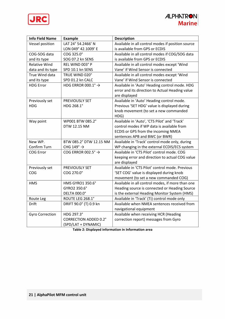
21 | AlphaPilot MFM control unit
Info Field Name Example Description
Vessel position LAT 24° 54.2466’ N LON 049° 42.1009’ E
Available in all control modes if position source is available from GPS or ECDIS
COG-SOG data and its type
COG 325.0° SOG 07.2 kn SENS
Available in all control modes if COG/SOG data is available from GPS or ECDIS
Relative Wind data and its type
REL WIND 003° P SPD 10.1 kn SENS
Available in all control modes except ‘Wind Vane’ if Wind Sensor is connected
True Wind data and its type
TRUE WIND 020° SPD 01.2 kn CALC
Available in all control modes except ‘Wind Vane’ if Wind Sensor is connected
HDG Error HDG ERROR 000.1° → Available in ‘Auto’ Heading control mode. HDG error and its direction to Actual Heading value are displayed
Previously set HDG
PREVIOUSLY SET HDG 268.1°
Available in ‘Auto’ Heading control mode. Previous ‘SET HDG’ value is displayed during knob movement (to set a new commanded HDG)
Way point WP001 BTW 085.2° DTW 12.15 NM
Available in ‘Auto’, ‘CTS Pilot’ and ‘Track’ control modes if WP data is available from ECDIS or GPS from the incoming NMEA sentences APB and BWC (or BWR)
New WP. Confirm Turn
BTW 085.2° DTW 12.15 NM CHG 149° →
Available in ‘Track’ control mode only, during WP changing in the external ECDIS/ECS system
COG Error COG ERROR 002.5° → Available in ‘CTS Pilot’ control mode. COG keeping error and direction to actual COG value are displayed
Previously set COG
PREVIOUSLY SET COG 270.0°
Available in ‘CTS Pilot’ control mode. Previous ‘SET COG’ value is displayed during knob movement (to set a new commanded COG)
HMS HMS GYRO1 350.6° GYRO2 350.6° DELTA 000.0°
Available in all control modes, if more than one Heading source is connected or Heading Source is the external Heading Monitor System (HMS)
Route Leg ROUTE LEG 268.1° Available in ‘Track’ (Ti) control mode only
Drift DRIFT 90.0° (T) 0.9 kn Available when NMEA sentences received from navigational equipment
Gyro Correction HDG 297.3° CORRECTION ADDED 0.2° (SPD/LAT + DYNAMIC)
Available when receiving HCR (Heading correction report) messages from Gyro
Table 2: Displayed information in Information area
22 | Operating modes
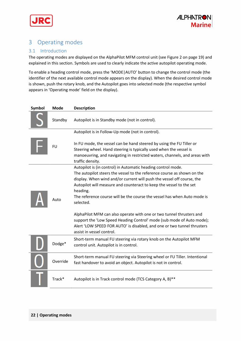
3 Operating modes
3.1 Introduction The operating modes are displayed on the AlphaPilot MFM control unit (see Figure 2 on page 19) and
explained in this section. Symbols are used to clearly indicate the active autopilot operating mode.
To enable a heading control mode, press the ‘MODE|AUTO’ button to change the control mode (the
identifier of the next available control mode appears on the display). When the desired control mode
is shown, push the rotary knob, and the Autopilot goes into selected mode (the respective symbol
appears in ‘Operating mode’ field on the display).
Symbol Mode Description
Standby Autopilot is in Standby mode (not in control).
FU
Autopilot is in Follow-Up mode (not in control).
In FU mode, the vessel can be hand steered by using the FU Tiller or
Steering wheel. Hand steering is typically used when the vessel is
manoeuvring, and navigating in restricted waters, channels, and areas with
traffic density.
Auto
Autopilot is (in control) in Automatic heading control mode.
The autopilot steers the vessel to the reference course as shown on the
display. When wind and/or current will push the vessel off course, the
Autopilot will measure and counteract to keep the vessel to the set
heading.
The reference course will be the course the vessel has when Auto mode is
selected.
AlphaPilot MFM can also operate with one or two tunnel thrusters and
support the ‘Low Speed Heading Control’ mode (sub mode of Auto mode);
Alert ‘LOW SPEED FOR AUTO’ is disabled, and one or two tunnel thrusters
assist in vessel control.
Dodge* Short-term manual FU steering via rotary knob on the Autopilot MFM
control unit. Autopilot is in control.
Override Short-term manual FU steering via Steering wheel or FU Tiller. Intentional
fast handover to avoid an object. Autopilot is not in control.
Track* Autopilot is in Track control mode (TCS Category A, B)**
F
23 | Operating modes
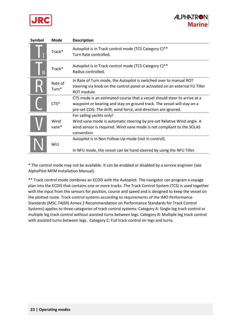
Symbol Mode Description
Track* Autopilot is in Track control mode (TCS Category C)**
Turn Rate controlled.
Track* Autopilot is in Track control mode (TCS Category C)**
Radius controlled.
Rate of
Turn*
In Rate of Turn mode, the Autopilot is switched over to manual ROT
steering via knob on the control panel or activated on an external FU Tiller
ROT module.
CTS*
CTS mode is an estimated course that a vessel should steer to arrive at a
waypoint or bearing and stay on ground track. The vessel will stay on a
pre-set COG. The drift, wind force, and direction are ignored.
Wind
vane*
For sailing yachts only!
Wind vane mode is automatic steering by pre-set Relative Wind angle. A
wind sensor is required. Wind vane mode is not compliant to the SOLAS
convention.
NFU
Autopilot is in Non-Follow-Up mode (not in control).
In NFU mode, the vessel can be hand steered by using the NFU Tiller.
* The control mode may not be available. It can be enabled or disabled by a service engineer (see
AlphaPilot MFM Installation Manual).
** Track control mode combines an ECDIS with the Autopilot. The navigator can program a voyage
plan into the ECDIS that contains one or more tracks. The Track Control System (TCS) is used together
with the input from the sensors for position, course and speed and is designed to keep the vessel on
the plotted route. Track control systems according to requirements of the IMO Performance
Standards (MSC.74(69) Annex 2 Recommendation on Performance Standards for Track Control
Systems) applies to three categories of track control systems: Category A: Single leg track control or
multiple leg track control without assisted turns between legs. Category B: Multiple leg track control
with assisted turns between legs. Category C: Full track control on legs and turns.
N
24 | Operating modes
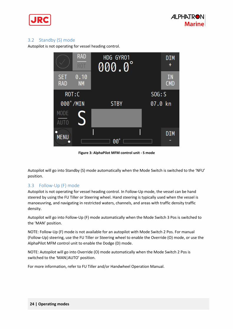
3.2 Standby (S) mode Autopilot is not operating for vessel heading control.
Figure 3: AlphaPilot MFM control unit - S mode
Autopilot will go into Standby (S) mode automatically when the Mode Switch is switched to the ‘NFU’
position.
3.3 Follow-Up (F) mode Autopilot is not operating for vessel heading control. In Follow-Up mode, the vessel can be hand
steered by using the FU Tiller or Steering wheel. Hand steering is typically used when the vessel is
manoeuvring, and navigating in restricted waters, channels, and areas with traffic density traffic
density.
Autopilot will go into Follow-Up (F) mode automatically when the Mode Switch 3 Pos is switched to
the ‘MAN’ position.
NOTE: Follow-Up (F) mode is not available for an autopilot with Mode Switch 2 Pos. For manual
(Follow-Up) steering, use the FU Tiller or Steering wheel to enable the Override (O) mode, or use the
AlphaPilot MFM control unit to enable the Dodge (D) mode.
NOTE: Autopilot will go into Override (O) mode automatically when the Mode Switch 2 Pos is
switched to the ‘MAN|AUTO’ position.
For more information, refer to FU Tiller and/or Handwheel Operation Manual.
25 | Operating modes
3.4 Auto (A) control mode
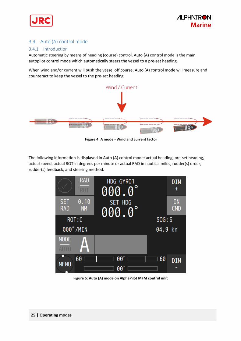
3.4.1 Introduction Automatic steering by means of heading (course) control. Auto (A) control mode is the main
autopilot control mode which automatically steers the vessel to a pre-set heading.
When wind and/or current will push the vessel off course, Auto (A) control mode will measure and
counteract to keep the vessel to the pre-set heading.
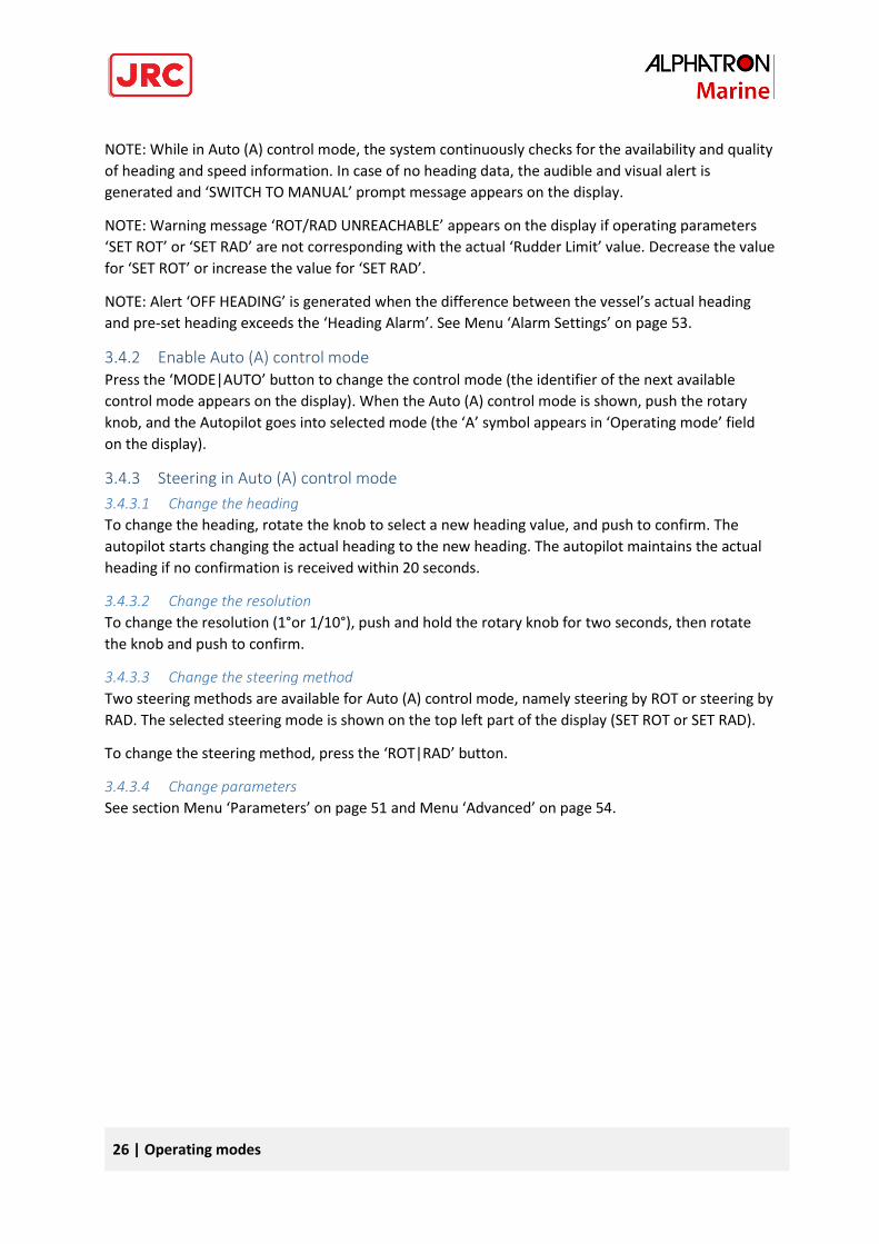
The following information is displayed in Auto (A) control mode: actual heading, pre-set heading,
actual speed, actual ROT in degrees per minute or actual RAD in nautical miles, rudder(s) order,
rudder(s) feedback, and steering method.
Figure 4: A mode - Wind and current factor
Figure 5: Auto (A) mode on AlphaPilot MFM control unit
26 | Operating modes
NOTE: While in Auto (A) control mode, the system continuously checks for the availability and quality
of heading and speed information. In case of no heading data, the audible and visual alert is
generated and ‘SWITCH TO MANUAL’ prompt message appears on the display.
NOTE: Warning message ‘ROT/RAD UNREACHABLE’ appears on the display if operating parameters
‘SET ROT’ or ‘SET RAD’ are not corresponding with the actual ‘Rudder Limit’ value. Decrease the value
for ‘SET ROT’ or increase the value for ‘SET RAD’.
NOTE: Alert ‘OFF HEADING’ is generated when the difference between the vessel’s actual heading
and pre-set heading exceeds the ‘Heading Alarm’. See Menu ‘Alarm Settings’ on page 53.
3.4.2 Enable Auto (A) control mode Press the ‘MODE|AUTO’ button to change the control mode (the identifier of the next available
control mode appears on the display). When the Auto (A) control mode is shown, push the rotary
knob, and the Autopilot goes into selected mode (the ‘A’ symbol appears in ‘Operating mode’ field
on the display).
3.4.3 Steering in Auto (A) control mode
3.4.3.1 Change the heading
To change the heading, rotate the knob to select a new heading value, and push to confirm. The
autopilot starts changing the actual heading to the new heading. The autopilot maintains the actual
heading if no confirmation is received within 20 seconds.
3.4.3.2 Change the resolution
To change the resolution (1°or 1/10°), push and hold the rotary knob for two seconds, then rotate
the knob and push to confirm.
3.4.3.3 Change the steering method
Two steering methods are available for Auto (A) control mode, namely steering by ROT or steering by
RAD. The selected steering mode is shown on the top left part of the display (SET ROT or SET RAD).
To change the steering method, press the ‘ROT|RAD’ button.
3.4.3.4 Change parameters
See section Menu ‘Parameters’ on page 51 and Menu ‘Advanced’ on page 54.
27 | Operating modes
3.5 Low Speed Heading Control mode
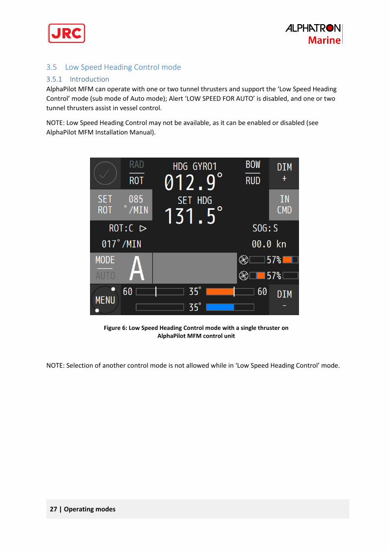
3.5.1 Introduction AlphaPilot MFM can operate with one or two tunnel thrusters and support the ‘Low Speed Heading
Control’ mode (sub mode of Auto mode); Alert ‘LOW SPEED FOR AUTO’ is disabled, and one or two
tunnel thrusters assist in vessel control.
NOTE: Low Speed Heading Control may not be available, as it can be enabled or disabled (see
AlphaPilot MFM Installation Manual).
NOTE: Selection of another control mode is not allowed while in ‘Low Speed Heading Control’ mode.
Figure 6: Low Speed Heading Control mode with a single thruster on AlphaPilot MFM control unit
28 | Operating modes
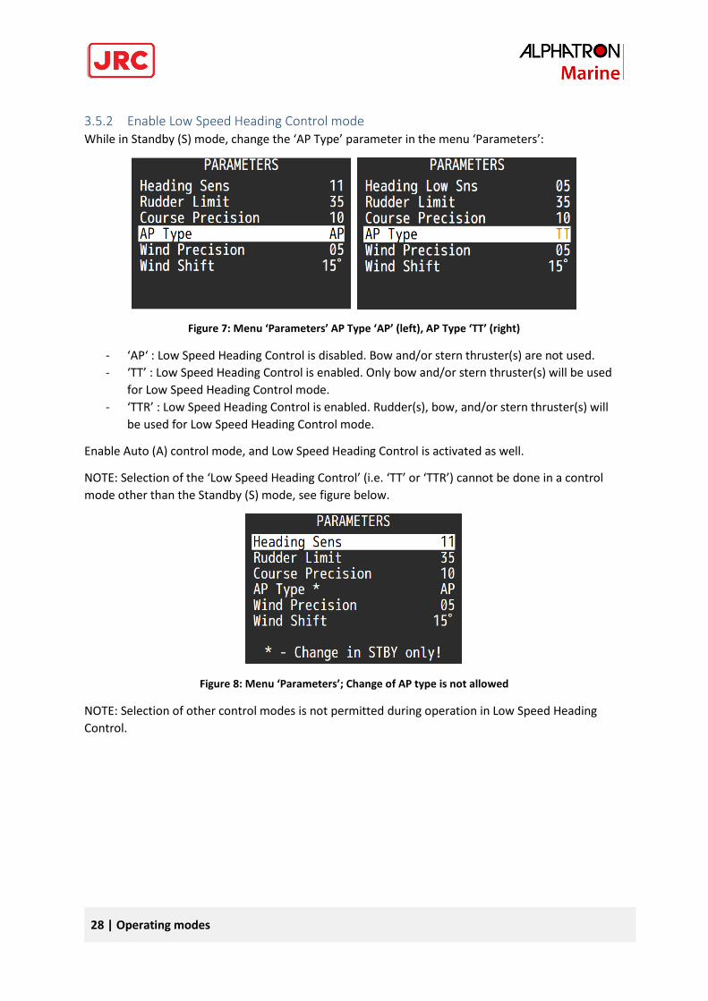
3.5.2 Enable Low Speed Heading Control mode While in Standby (S) mode, change the ‘AP Type’ parameter in the menu ‘Parameters’:
Figure 7: Menu ‘Parameters’ AP Type ‘AP’ (left), AP Type ‘TT’ (right)
- ‘AP‘ : Low Speed Heading Control is disabled. Bow and/or stern thruster(s) are not used.
- ‘TT’ : Low Speed Heading Control is enabled. Only bow and/or stern thruster(s) will be used
for Low Speed Heading Control mode.
- ‘TTR’ : Low Speed Heading Control is enabled. Rudder(s), bow, and/or stern thruster(s) will
be used for Low Speed Heading Control mode.
Enable Auto (A) control mode, and Low Speed Heading Control is activated as well.
NOTE: Selection of the ‘Low Speed Heading Control’ (i.e. ‘TT’ or ‘TTR’) cannot be done in a control
mode other than the Standby (S) mode, see figure below.
Figure 8: Menu ‘Parameters’; Change of AP type is not allowed
NOTE: Selection of other control modes is not permitted during operation in Low Speed Heading
Control.
29 | Operating modes
3.5.3 Steering in Low Speed Heading Control mode NOTE: In case of a single failure during operation in ‘Low Speed Heading Control’ mode, the
AlphaPilot MFM will use the following procedure to keep a ‘SET HDG’ as accurate as possible:
- Single thruster failure
Autopilot uses the second thruster (if available) and single, linked, or independent rudders –
if ‘AP Type’ is set to ‘TT’.
- Single rudder failure
Autopilot uses thruster(s) in ‘TT’ mode or thruster(s) and second independent rudder (if
available in ‘TTR’ mode).
In case of an emergency, always switch the Mode Switch to the ‘NFU’ position!
3.5.3.1 Change the heading
To change the heading, rotate the knob to select a new heading value, and push to confirm. The
autopilot starts changing the actual heading to the new heading. The autopilot maintains the actual
heading if no confirmation is received within 20 seconds.
3.5.3.2 Change the sensitivity of the thruster/heading keeping
Parameter ‘Heading Low Sns’ specifies the sensitivity of the thruster/heading keeping in the Low
Speed Heading Control mode.
Accepted range is 1 to 30. Recommended range is 5 to 12. Increase the parameter value if the vessel
responds too slowly to sea conditions, i.e. at significant off-headings the rudder angle changes and
forces to tunnel thruster(s) are not enough.
30 | Operating modes
3.6 Dodge (D) mode
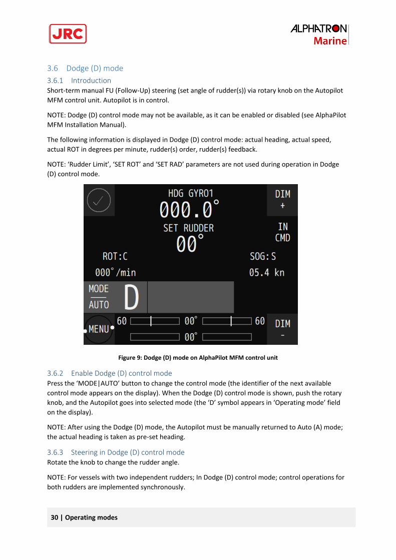
3.6.1 Introduction Short-term manual FU (Follow-Up) steering (set angle of rudder(s)) via rotary knob on the Autopilot
MFM control unit. Autopilot is in control.
NOTE: Dodge (D) control mode may not be available, as it can be enabled or disabled (see AlphaPilot
MFM Installation Manual).
The following information is displayed in Dodge (D) control mode: actual heading, actual speed,
actual ROT in degrees per minute, rudder(s) order, rudder(s) feedback.
NOTE: ‘Rudder Limit’, ‘SET ROT’ and ‘SET RAD’ parameters are not used during operation in Dodge
(D) control mode.
Figure 9: Dodge (D) mode on AlphaPilot MFM control unit
3.6.2 Enable Dodge (D) control mode Press the ‘MODE|AUTO’ button to change the control mode (the identifier of the next available
control mode appears on the display). When the Dodge (D) control mode is shown, push the rotary
knob, and the Autopilot goes into selected mode (the ‘D’ symbol appears in ‘Operating mode’ field
on the display).
NOTE: After using the Dodge (D) mode, the Autopilot must be manually returned to Auto (A) mode;
the actual heading is taken as pre-set heading.
3.6.3 Steering in Dodge (D) control mode Rotate the knob to change the rudder angle.
NOTE: For vessels with two independent rudders; In Dodge (D) control mode; control operations for
both rudders are implemented synchronously.
31 | Operating modes
3.7 Override (O) control mode
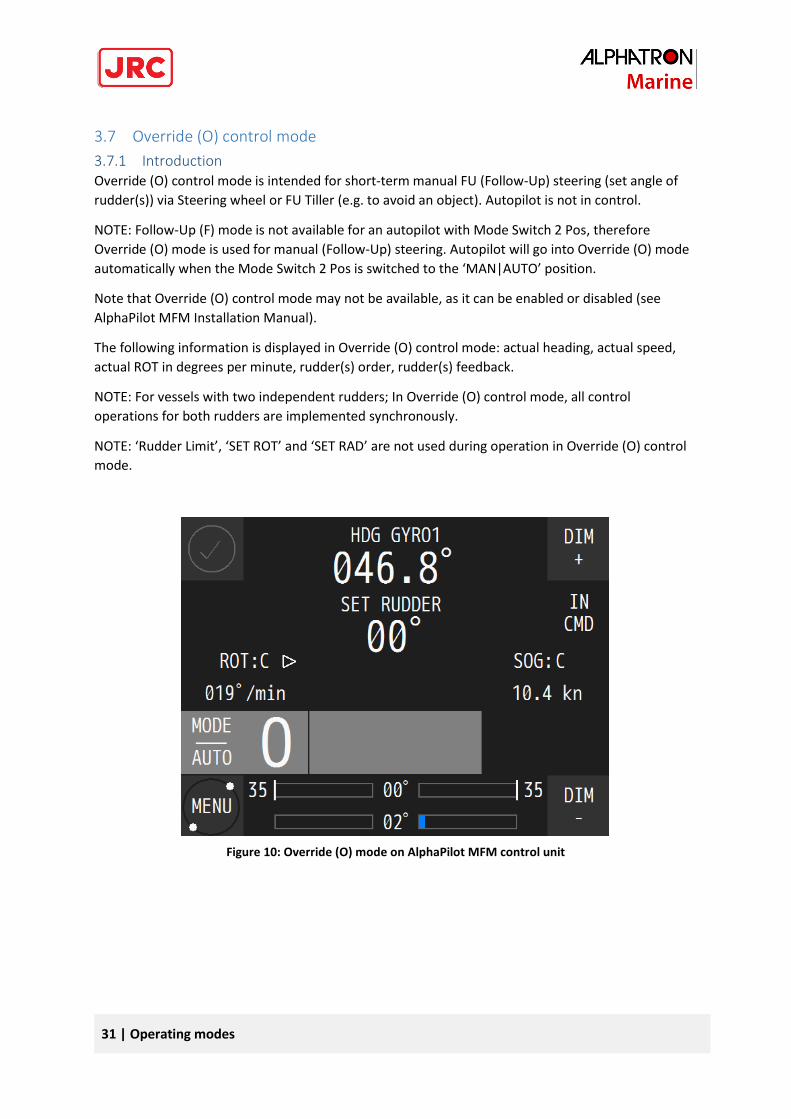
3.7.1 Introduction Override (O) control mode is intended for short-term manual FU (Follow-Up) steering (set angle of
rudder(s)) via Steering wheel or FU Tiller (e.g. to avoid an object). Autopilot is not in control.
NOTE: Follow-Up (F) mode is not available for an autopilot with Mode Switch 2 Pos, therefore
Override (O) mode is used for manual (Follow-Up) steering. Autopilot will go into Override (O) mode
automatically when the Mode Switch 2 Pos is switched to the ‘MAN|AUTO’ position.
Note that Override (O) control mode may not be available, as it can be enabled or disabled (see
AlphaPilot MFM Installation Manual).
The following information is displayed in Override (O) control mode: actual heading, actual speed,
actual ROT in degrees per minute, rudder(s) order, rudder(s) feedback.
NOTE: For vessels with two independent rudders; In Override (O) control mode, all control
operations for both rudders are implemented synchronously.
NOTE: ‘Rudder Limit’, ‘SET ROT’ and ‘SET RAD’ are not used during operation in Override (O) control
mode.
Figure 10: Override (O) mode on AlphaPilot MFM control unit
32 | Operating modes
3.7.2 Enable Override (O) control mode Override (O) control mode is only enabled via Steering wheel or FU Tiller.
Press the ‘FU’ button on the FU Tiller, and the control mode indicator ‘FU’ and handle indicator on
the FU Tiller will illuminate, meaning that the respective mode (i.e. Override (O) control mode) and
the handle is enabled. and the Autopilot goes into selected mode (the ‘O’ symbol appears in
‘Operating mode’ field on the display).
The AlphaPilot MFM control unit generates time limited audible signal and displays a warning
message ‘OVERRIDE’.
NOTE: After using the Override (O) control mode, the Autopilot must be manually returned to Auto
(A) mode; the actual heading is taken as pre-set heading.
3.7.3 Steering in Override (O) control mode Rotate the handle to change the rudder angle. For more details, refer to the FU Tiller Operation
manual.
33 | Operating modes
3.8 Track (T) control modes
3.8.1 Introduction Track (T) control mode (also referred to as ‘Track steering’) combines an ECDIS with the Autopilot.
The navigator can program a voyage plan into the ECDIS that contains one or more tracks.
The TCS (Track Control System) is used together with the input from the sensors for position, course
and speed and is designed to keep the vessel on the plotted route.
Track Control Systems according to requirements of the IMO Performance Standards (MSC.74(69)
Annex 2 Recommendation on Performance Standards for Track Control Systems) applies to three
categories of Track Control Systems:
- Category A: Single leg track control or multiple leg track control without assisted turns
between legs.
- Category B: Multiple leg track control with assisted turns between legs.
- Category C: Full track control on legs and turns.
The Autopilot covers two types of Track control modes:
- Track (T) control mode: Track control mode as per Category A, B
- Track (Tn or Ti) control mode: Track control mode as per Category C
34 | Operating modes
3.8.2 Track (T) control mode, TCS category A, B
3.8.2.1 Introduction
Note that Track (T) control mode, TCS category A, B, may not be available, as it can be enabled or
disabled (see AlphaPilot MFM Installation Manual).
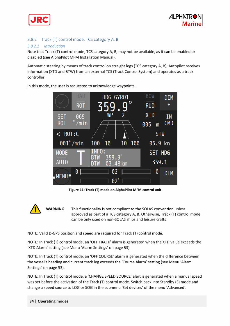
Automatic steering by means of track control on straight legs (TCS category A, B); Autopilot receives
information (XTD and BTW) from an external TCS (Track Control System) and operates as a track
controller.
In this mode, the user is requested to acknowledge waypoints.
WARNING
This functionality is not compliant to the SOLAS convention unless approved as part of a TCS category A, B. Otherwise, Track (T) control mode can be only used on non-SOLAS ships and leisure crafts
NOTE: Valid D-GPS position and speed are required for Track (T) control mode.
NOTE: In Track (T) control mode, an ‘OFF TRACK’ alarm is generated when the XTD value exceeds the
‘XTD Alarm’ setting (see Menu ‘Alarm Settings’ on page 53).
NOTE: In Track (T) control mode, an ‘OFF COURSE’ alarm is generated when the difference between
the vessel’s heading and current track leg exceeds the ‘Course Alarm’ setting (see Menu ‘Alarm
Settings’ on page 53).
NOTE: In Track (T) control mode, a ‘CHANGE SPEED SOURCE’ alert is generated when a manual speed
was set before the activation of the Track (T) control mode. Switch back into Standby (S) mode and
change a speed source to LOG or SOG in the submenu ‘Set devices’ of the menu ‘Advanced’.
Figure 11: Track (T) mode on AlphaPilot MFM control unit
35 | Operating modes
NOTE: While in Track (T) control mode, the system continuously checks for the availability and quality
of APB, BWC, BWR and VTG, GGA, GLL messages. In case if these messages are missing, the ‘TRACK
FAIL’ alarm is generated and ‘SWITCHED TO AUTO’ prompt message appears on the control panel
display. In this case actual heading is taken over as a pre-set heading in Auto (A) control mode
automatically.
The following information is displayed in Track (T) control mode: actual heading, pre-set heading,
actual speed, actual ROT in degrees per minute or actual RAD in nautical miles, rudder(s) order,
rudder(s) feedback, steering method.
NOTE: Steering by RAD is recommended in combination with an external ECS system/ECDIS.
NOTE: While in Auto (A) control mode, the system continuously checks for the availability and quality
of heading and speed information. In case of no heading data, the audible and visual alert is
generated and ‘SWITCH TO MANUAL’ prompt message appears on the display.
3.8.2.2 Enable Track (T) control mode
Press the ‘MODE|AUTO’ button to change the control mode (the identifier of the next available
control mode appears on the display). When the Track (T) control mode is shown, push the rotary
knob, and the AlphaPilot MFM system goes into selected mode (the ‘T’ symbol appears in ‘Operating
mode’ field on the display).
36 | Operating modes
3.8.2.3 Steering in Track (T) control mode
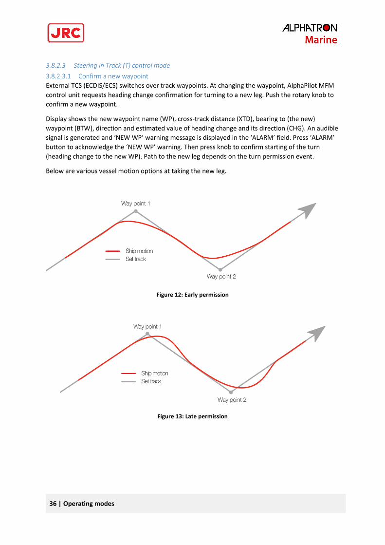
3.8.2.3.1 Confirm a new waypoint
External TCS (ECDIS/ECS) switches over track waypoints. At changing the waypoint, AlphaPilot MFM
control unit requests heading change confirmation for turning to a new leg. Push the rotary knob to
confirm a new waypoint.
Display shows the new waypoint name (WP), cross-track distance (XTD), bearing to (the new)
waypoint (BTW), direction and estimated value of heading change and its direction (CHG). An audible
signal is generated and ‘NEW WP’ warning message is displayed in the ‘ALARM’ field. Press ‘ALARM’
button to acknowledge the ‘NEW WP’ warning. Then press knob to confirm starting of the turn
(heading change to the new WP). Path to the new leg depends on the turn permission event.
Below are various vessel motion options at taking the new leg.
Figure 13: Late permission
Figure 12: Early permission
37 | Operating modes
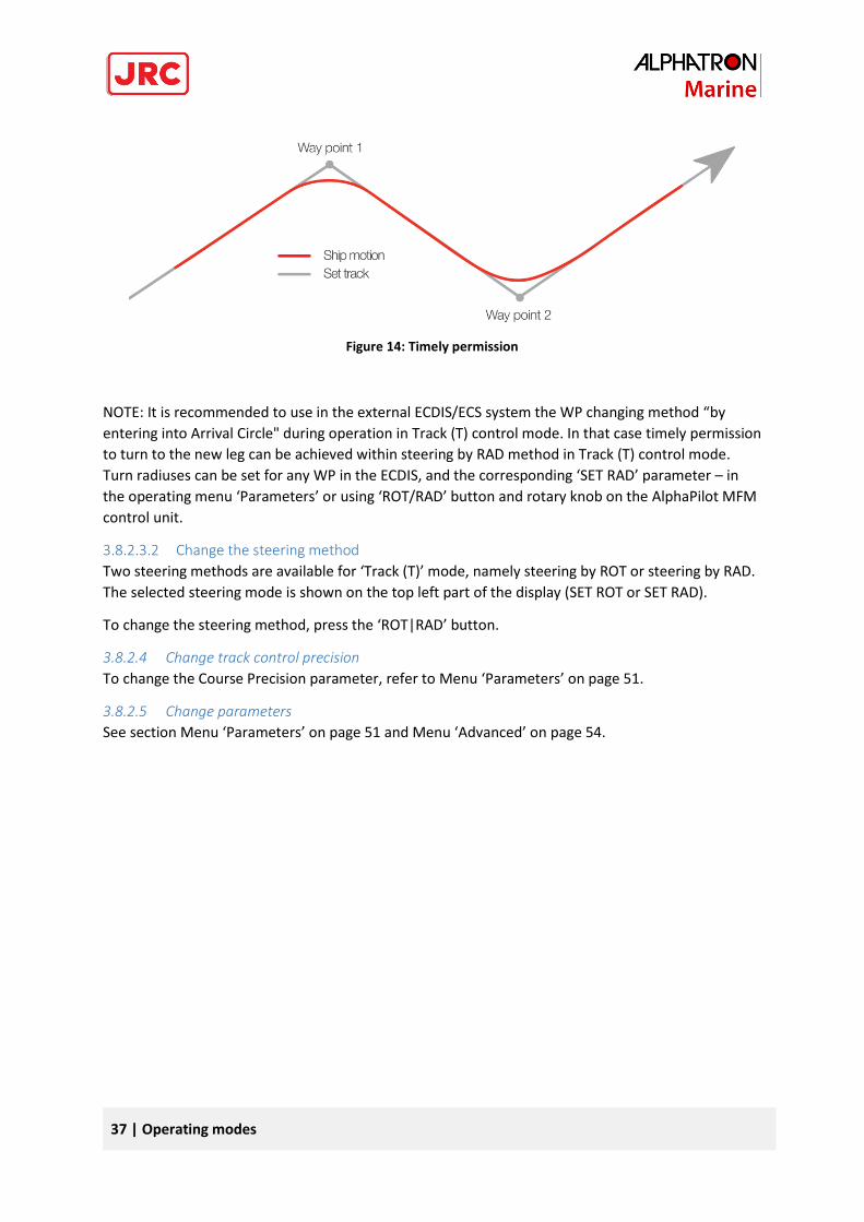
Figure 14: Timely permission
NOTE: It is recommended to use in the external ECDIS/ECS system the WP changing method “by
entering into Arrival Circle" during operation in Track (T) control mode. In that case timely permission
to turn to the new leg can be achieved within steering by RAD method in Track (T) control mode.
Turn radiuses can be set for any WP in the ECDIS, and the corresponding ‘SET RAD’ parameter – in
the operating menu ‘Parameters’ or using ‘ROT/RAD’ button and rotary knob on the AlphaPilot MFM
control unit.
3.8.2.3.2 Change the steering method
Two steering methods are available for ‘Track (T)’ mode, namely steering by ROT or steering by RAD.
The selected steering mode is shown on the top left part of the display (SET ROT or SET RAD).
To change the steering method, press the ‘ROT|RAD’ button.
3.8.2.4 Change track control precision
To change the Course Precision parameter, refer to Menu ‘Parameters’ on page 51.
3.8.2.5 Change parameters
See section Menu ‘Parameters’ on page 51 and Menu ‘Advanced’ on page 54.
38 | Operating modes
3.8.3 Track (TN or TI) control mode, TCS category C
3.8.3.1 Introduction
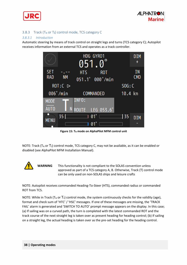
Automatic steering by means of track control on straight legs and turns (TCS category C); Autopilot
receives information from an external TCS and operates as a track controller.
NOTE: Track (TN or TI) control mode, TCS category C, may not be available, as it can be enabled or
disabled (see AlphaPilot MFM Installation Manual).
WARNING
This functionality is not compliant to the SOLAS convention unless approved as part of a TCS category A, B. Otherwise, Track (T) control mode can be only used on non-SOLAS ships and leisure crafts
NOTE: Autopilot receives commanded Heading-To-Steer (HTS), commanded radius or commanded
ROT from TCS.
NOTE: While in Track (TN or TI) control mode, the system continuously checks for the validity (age),
format and check sum of ‘HTC’ / ‘HSC’ messages. If one of these messages are missing, the ‘TRACK
FAIL’ alarm is generated and ‘SWITCH TO AUTO’ prompt message appears on the display. In this case;
(a) If sailing was on a curved path, the turn is completed with the latest commanded ROT and the
track course of the next straight leg is taken over as present heading for heading control; (b) If sailing
on a straight leg, the actual heading is taken over as the pre-set heading for the heading control.
Figure 16: Track (Ti) mode on AlphaPilot MFM control unit Figure 15: TN mode on AlphaPilot MFM control unit
39 | Operating modes
NOTE: In Track (TN or TI) control mode, a ‘CHANGE SPEED SOURCE’ alert is generated when a manual
speed was set before the activation of the Track (T) control mode. Switch back into Standby (S) mode
and change a speed source to LOG or SOG in the submenu ‘Set devices’ of the menu ‘Advanced’.
NOTE: ‘Rudder Limit’, ‘SET ROT’ and ‘SET RAD’ parameters are not used during operation in Track (TN
or TI) control mode. AlphaPilot uses incoming HTC sentences (commanded HTS, ROT or RAD) from an
external TCS.
3.8.3.2 Enable Track (TN or TI) control mode
Press the ‘MODE|AUTO’ button to change the control mode (the identifier of the next available
control mode appears on the display). When Track (TN or TI) control mode is shown, push the rotary
knob, and the Autopilot goes into selected mode (the ‘Tn’ symbol appears in ‘Operating mode’ field
on the display).
3.8.3.3 Steering in Track (TN or TI) control mode
Commanded heading to steer and rate of turn (HTC, HSC or proprietary messages) is set by an
external TCS Category C.
3.8.3.4 Change parameters
See section Menu ‘Parameters’ on page 51 and Menu ‘Advanced’ on page 54.
40 | Operating modes
3.9 Rate of Turn (R) control mode
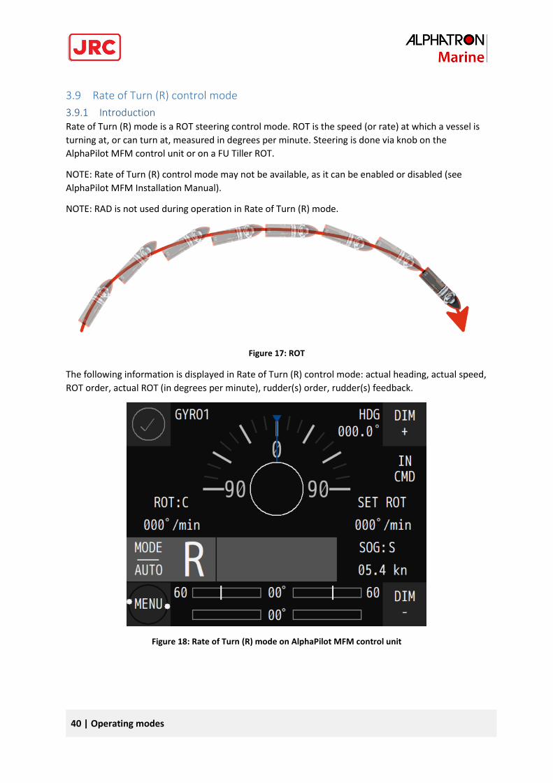
3.9.1 Introduction Rate of Turn (R) mode is a ROT steering control mode. ROT is the speed (or rate) at which a vessel is
turning at, or can turn at, measured in degrees per minute. Steering is done via knob on the
AlphaPilot MFM control unit or on a FU Tiller ROT.
NOTE: Rate of Turn (R) control mode may not be available, as it can be enabled or disabled (see
AlphaPilot MFM Installation Manual).
NOTE: RAD is not used during operation in Rate of Turn (R) mode.
Figure 17: ROT
The following information is displayed in Rate of Turn (R) control mode: actual heading, actual speed,
ROT order, actual ROT (in degrees per minute), rudder(s) order, rudder(s) feedback.
Figure 18: Rate of Turn (R) mode on AlphaPilot MFM control unit
41 | Operating modes
3.9.2 Enable Rate of Turn (R) mode
3.9.2.1 Enable Rate of Turn (R) mode from FU Tiller ROT
Press the ‘ROT’ button on the FU Tiller ROT, and the control mode indicator ‘ROT’ and handle
indicator on the FU Tiller ROT will illuminate, meaning that the respective mode (i.e. Rate of Turn (R)
control mode) and the handle is enabled. and the Autopilot goes into selected mode (the ‘R’ symbol
appears in ‘Operating mode’ field on the display).
For more details, refer to the FU Tiller ROT Operation Manual.
NOTE: The ‘FU’ button on other Tiller types (FU Tiller or FU Tiller S/is) used to enable the Dodge (D)
control mode.
3.9.2.2 Enable Rate of Turn (R) mode from AlphaPilot MFM control unit
Press the ‘MODE|AUTO’ button to change the control mode (the identifier of the next available
control mode appears on the display). When the Rate of Turn (R) control mode is shown, push the
rotary knob, and the Autopilot goes into selected mode (the ‘R’ symbol appears in ‘Operating mode’
field on the display).
NOTE: After using the Rate of Turn (R) control mode, the Autopilot must be manually returned to
Auto (A) mode; the actual heading is taken as pre-set heading.
3.9.3 Steering in Rate of Turn (R) mode Rotate the handle to change the ROT order.
3.9.4 Change parameters See section Menu ‘Parameters’ on page 51 and Menu ‘Advanced’ on page 54.
42 | Operating modes
3.10 CTS pilot (C) control mode
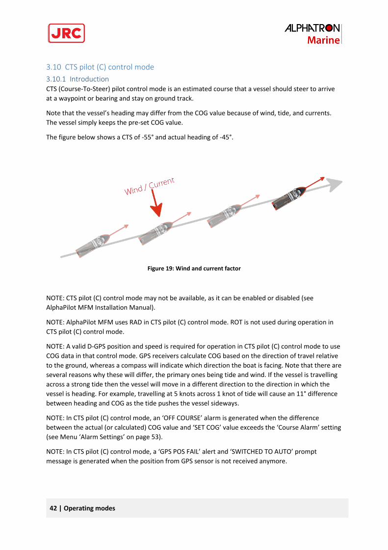
3.10.1 Introduction CTS (Course-To-Steer) pilot control mode is an estimated course that a vessel should steer to arrive
at a waypoint or bearing and stay on ground track.
Note that the vessel’s heading may differ from the COG value because of wind, tide, and currents.
The vessel simply keeps the pre-set COG value.
The figure below shows a CTS of -55° and actual heading of -45°.
Figure 19: Wind and current factor
NOTE: CTS pilot (C) control mode may not be available, as it can be enabled or disabled (see
AlphaPilot MFM Installation Manual).
NOTE: AlphaPilot MFM uses RAD in CTS pilot (C) control mode. ROT is not used during operation in
CTS pilot (C) control mode.
NOTE: A valid D-GPS position and speed is required for operation in CTS pilot (C) control mode to use
COG data in that control mode. GPS receivers calculate COG based on the direction of travel relative
to the ground, whereas a compass will indicate which direction the boat is facing. Note that there are
several reasons why these will differ, the primary ones being tide and wind. If the vessel is travelling
across a strong tide then the vessel will move in a different direction to the direction in which the
vessel is heading. For example, travelling at 5 knots across 1 knot of tide will cause an 11° difference
between heading and COG as the tide pushes the vessel sideways.
NOTE: In CTS pilot (C) control mode, an ‘OFF COURSE’ alarm is generated when the difference
between the actual (or calculated) COG value and ‘SET COG’ value exceeds the ‘Course Alarm’ setting
(see Menu ‘Alarm Settings’ on page 53).
NOTE: In CTS pilot (C) control mode, a ‘GPS POS FAIL’ alert and ‘SWITCHED TO AUTO’ prompt
message is generated when the position from GPS sensor is not received anymore.
43 | Operating modes
NOTE: In CTS pilot (C) control mode, a ‘CHANGE SPEED SOURCE’ alert is generated when a manual
speed was set before the activation of the CTS pilot (C) control mode. Switch back into Standby (S)
mode and change a speed source to SOG in the submenu ‘Set devices’ of the menu ‘Advanced’.
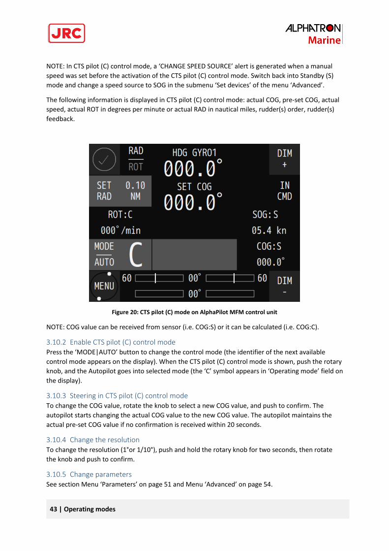
The following information is displayed in CTS pilot (C) control mode: actual COG, pre-set COG, actual
speed, actual ROT in degrees per minute or actual RAD in nautical miles, rudder(s) order, rudder(s)
feedback.
Figure 20: CTS pilot (C) mode on AlphaPilot MFM control unit
NOTE: COG value can be received from sensor (i.e. COG:S) or it can be calculated (i.e. COG:C).
3.10.2 Enable CTS pilot (C) control mode Press the ‘MODE|AUTO’ button to change the control mode (the identifier of the next available
control mode appears on the display). When the CTS pilot (C) control mode is shown, push the rotary
knob, and the Autopilot goes into selected mode (the ‘C’ symbol appears in ‘Operating mode’ field on
the display).
3.10.3 Steering in CTS pilot (C) control mode To change the COG value, rotate the knob to select a new COG value, and push to confirm. The
autopilot starts changing the actual COG value to the new COG value. The autopilot maintains the
actual pre-set COG value if no confirmation is received within 20 seconds.
3.10.4 Change the resolution To change the resolution (1°or 1/10°), push and hold the rotary knob for two seconds, then rotate
the knob and push to confirm.
3.10.5 Change parameters See section Menu ‘Parameters’ on page 51 and Menu ‘Advanced’ on page 54.
44 | Operating modes
3.11 Wind vane (V) control mode
3.11.1 Introduction For sailing yachts only. This control mode is intended for long sailing cruises at open sea when it is
comfortable to steer after the wind. When the wind changes the autopilot adapts to a new course
where the relative angle to the wind is maintained. When the boat tacks, the new heading will be the
same relative wind angle on the opposite side of the boat.
This control mode is not compliant to the SOLAS convention. Automatic steering by the pre-set
relative wind angle. A wind sensor is required.
NOTE: AlphaPilot MFM uses ROT in Wind vane (V) control mode. RAD is not used during operation in
Wind vane (V) control mode.
NOTE: Wind vane (V) control mode may not be available, as it can be enabled or disabled (see
AlphaPilot MFM Installation Manual).
NOTE: In Wind vane (V) control mode, Valid Wind data from the Wind sensor (Anemometer) is
required, otherwise ‘INVALID WIND DATA’ alarm message appears on the screen.
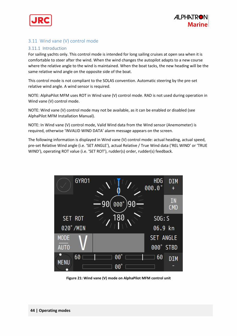
The following information is displayed in Wind vane (V) control mode: actual heading, actual speed,
pre-set Relative Wind angle (i.e. ‘SET ANGLE’), actual Relative / True Wind data (‘REL WIND’ or ‘TRUE
WIND’), operating ROT value (i.e. ‘SET ROT’), rudder(s) order, rudder(s) feedback.
Figure 21: Wind vane (V) mode on AlphaPilot MFM control unit
45 | Operating modes
3.11.2 Enable Wind vane (V) control mode Press the ‘MODE|AUTO’ button to change the control mode (the identifier of the next available
control mode appears on the display). When the Wind vane (V) control mode is shown, push the
rotary knob, and the Autopilot goes into selected mode (the ‘V’ symbol appears in ‘Operating mode’
field on the display).
When switching over to Wind vane (V) control mode, the actual Relative Wind Angle is taken as pre-
set Relative Wind Angle.
NOTE: Wind vane (V) control mode can be only activated when actual Wind Speed is a higher than a
‘Minimal Wind Speed’ pre-set parameter for this control mode (see AlphaPilot MFM Installation
Manual).
3.11.3 Steering in Wind vane (V) control mode To change the heading, rotate the knob to select a new Relative Wind Angle, and push to confirm.
The autopilot will adjust accordingly. The autopilot maintains the actual pre-set Relative Wind Angle
if no confirmation is received within 20 seconds.
NOTE: In Wind vane (V) control mode, a ‘WIND SHIFT’ alarm message is generated when the actual
Relative Wind angle deviates momentary from the pre-set Relative Wind Angle beyond a pre-set
limit. After that the AlphaPilot MFM is switched automatically to the Auto (A) control mode and
alarm ‘WINDVANE FAIL’ and a prompt message ‘SWITCHED TO AUTO’ is shown.
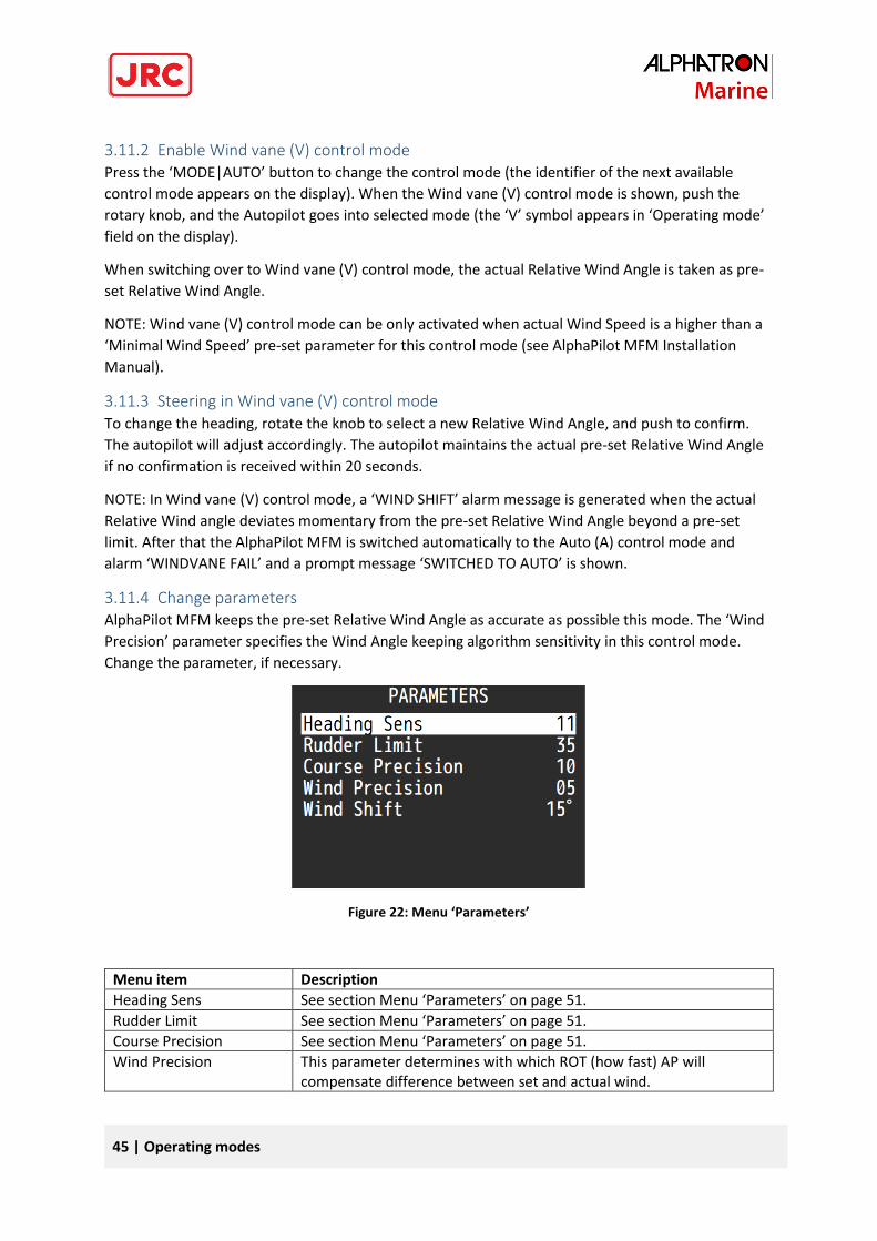
3.11.4 Change parameters AlphaPilot MFM keeps the pre-set Relative Wind Angle as accurate as possible this mode. The ‘Wind
Precision’ parameter specifies the Wind Angle keeping algorithm sensitivity in this control mode.
Change the parameter, if necessary.
Figure 22: Menu ‘Parameters’
Menu item Description
Heading Sens See section Menu ‘Parameters’ on page 51.
Rudder Limit See section Menu ‘Parameters’ on page 51.
Course Precision See section Menu ‘Parameters’ on page 51.
Wind Precision This parameter determines with which ROT (how fast) AP will compensate difference between set and actual wind.
46 | Operating modes
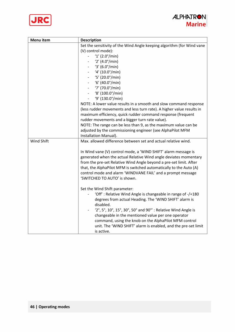
Menu item Description
Set the sensitivity of the Wind Angle keeping algorithm (for Wind vane (V) control mode):
- ‘1’ (2.0°/min) - ‘2’ (4.0°/min) - ‘3’ (6.0°/min) - ‘4’ (10.0°/min) - ‘5’ (20.0°/min) - ‘6’ (40.0°/min) - ‘7’ (70.0°/min) - ‘8’ (100.0°/min) - ‘9’ (130.0°/min)
NOTE: A lower value results in a smooth and slow command response (less rudder movements and less turn rate). A higher value results in maximum efficiency, quick rudder command response (frequent rudder movements and a bigger turn rate value). NOTE: The range can be less than 9, as the maximum value can be adjusted by the commissioning engineer (see AlphaPilot MFM Installation Manual).
Wind Shift Max. allowed difference between set and actual relative wind. In Wind vane (V) control mode, a ‘WIND SHIFT’ alarm message is generated when the actual Relative Wind angle deviates momentary from the pre-set Relative Wind Angle beyond a pre-set limit. After that, the AlphaPilot MFM is switched automatically to the Auto (A) control mode and alarm ‘WINDVANE FAIL’ and a prompt message ‘SWITCHED TO AUTO’ is shown. Set the Wind Shift parameter:
- ‘Off’ : Relative Wind Angle is changeable in range of -/+180 degrees from actual Heading. The ‘WIND SHIFT’ alarm is disabled.
- ‘2°, 5°, 10°, 15°, 30°, 50° and 90°’ : Relative Wind Angle is changeable in the mentioned value per one operator command, using the knob on the AlphaPilot MFM control unit. The ‘WIND SHIFT’ alarm is enabled, and the pre-set limit is active.
47 | Controls and functions
4 Controls and functions This section describes other controls and functions (not related to operating modes as described in
the previous section).
4.1 Reset and turn off Switch the AlphaPilot MFM system to Standby (S) mode. Switch the Alphatron Mode Switch 2 Pos (or
3 Pos) to the NFU position (or external mode selector on the Navigational Bridge in the appropriate
Standby mode).
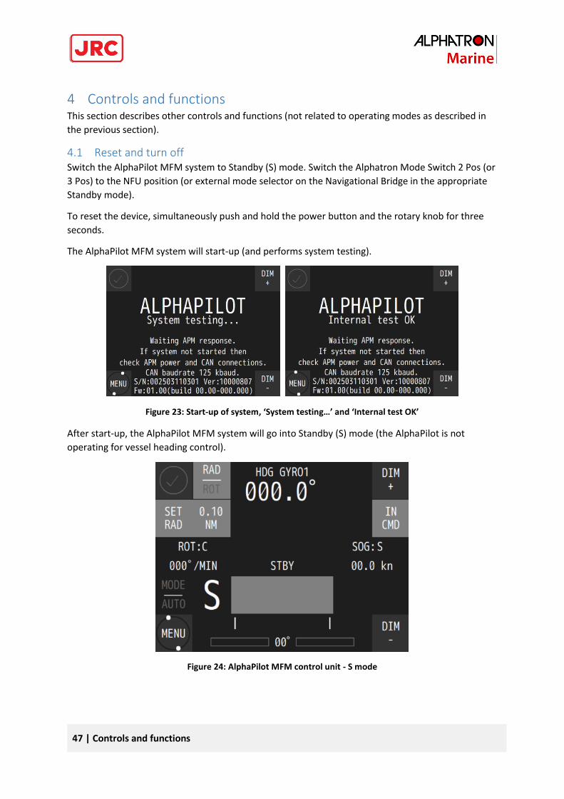
To reset the device, simultaneously push and hold the power button and the rotary knob for three
seconds.
The AlphaPilot MFM system will start-up (and performs system testing).
Figure 23: Start-up of system, ‘System testing…’ and ‘Internal test OK’
After start-up, the AlphaPilot MFM system will go into Standby (S) mode (the AlphaPilot is not
operating for vessel heading control).
Figure 24: AlphaPilot MFM control unit - S mode
48 | Controls and functions
The AlphaPilot MFM system is ready for operation. Switch the Alphatron Mode Switch to ‘AUTO’ (or
external mode selector on the Navigational Bridge in the appropriate Auto mode) to activate the
Auto (A) control mode.
NOTE: The AlphaPilot MFM can only be switched off by switching off the power (to prevent
accidental shutdown during operation).
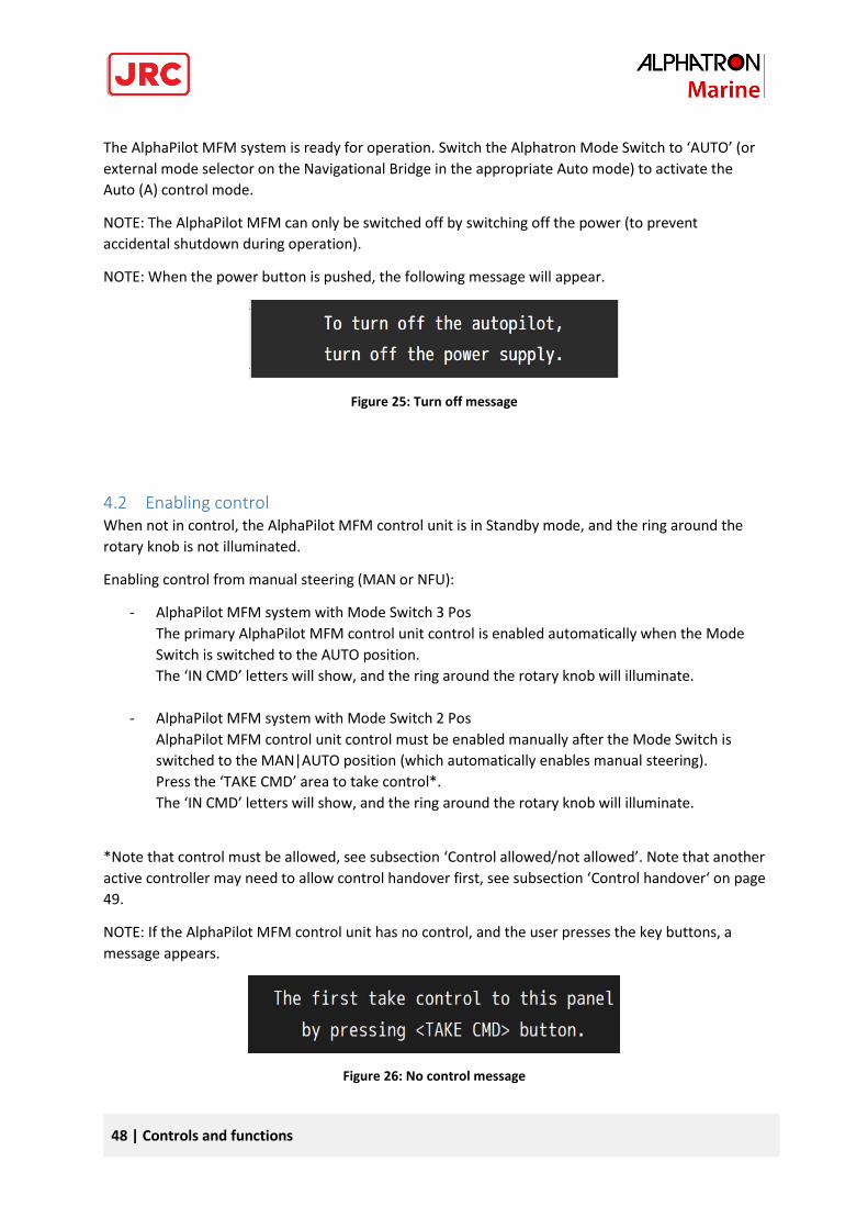
NOTE: When the power button is pushed, the following message will appear.
Figure 25: Turn off message
4.2 Enabling control When not in control, the AlphaPilot MFM control unit is in Standby mode, and the ring around the
rotary knob is not illuminated.
Enabling control from manual steering (MAN or NFU):
- AlphaPilot MFM system with Mode Switch 3 Pos
The primary AlphaPilot MFM control unit control is enabled automatically when the Mode
Switch is switched to the AUTO position.
The ‘IN CMD’ letters will show, and the ring around the rotary knob will illuminate.
- AlphaPilot MFM system with Mode Switch 2 Pos
AlphaPilot MFM control unit control must be enabled manually after the Mode Switch is
switched to the MAN|AUTO position (which automatically enables manual steering).
Press the ‘TAKE CMD’ area to take control*.
The ‘IN CMD’ letters will show, and the ring around the rotary knob will illuminate.
*Note that control must be allowed, see subsection ‘Control allowed/not allowed’. Note that another
active controller may need to allow control handover first, see subsection ‘Control handover‘ on page
49.
NOTE: If the AlphaPilot MFM control unit has no control, and the user presses the key buttons, a
message appears.
Figure 26: No control message
49 | Controls and functions
4.2.1 Control allowed/not allowed Control is allowed when the AlphaPilot MFM control unit shows ‘TAKE CMD’. Press the ‘TAKE CMD’
area to take control*.
* Note that another active controller may need to allow control handover first, see subsection
‘Control handover‘ on page 49.
4.2.2 Control handover If applicable, handover of control must be allowed first by the active controller to allow the
AlphaPilot MFM control unit to take control.
The method for control handover is pre-set during commissioning. Two system settings are possible,
namely ‘Take control’ or ‘Release/take control’.
4.2.2.1 Take control
Any controller can take control. Control handover allowance is not applicable.
Procedure for AlphaPilot MFM control unit:
- Push the ‘TAKE CMD’ button to enable control. The ‘TAKE CMD’ letters will change to ‘IN
CMD’, and the ring around the rotary knob will illuminate, meaning that the AlphaPilot MFM
control unit is in command and can take control, and that the rotary knob is enabled.
4.2.2.2 Release/take control
Any controller can take control, only when the active controller allows control handover.
Procedure for AlphaPilot MFM control unit:
- Take control
Allow control handover (i.e. release control) from the active controller. AlphaPilot MFM
control unit shows ‘TAKE CMD’ to indicate that take control is allowed.
Push the ‘TAKE CMD’ button to enable control. The ‘TAKE CMD’ letters will change to ‘IN
CMD’, and the ring around the rotary knob will illuminate, meaning that the AlphaPilot MFM
control unit is in command and can take control, and that the rotary knob is enabled.
- Release control
To allow control handover to another controller, push the ‘IN CMD’ area, until the ‘IN CMD’
text flashes (indication that control handover is allowed).
NOTE: The AlphaPilot MFM control unit stays in control until control is transferred to another
controller.
NOTE: The ‘IN CMD’ text keeps flashing until control is transferred to another controller. The
speaker produces one second beeps with one second interval to indicate that the operation
is not finished. There is no timeout.
NOTE: The AlphaPilot MFM control unit goes into Standby (S) mode when control is
transferred to another controller.
50 | Controls and functions
4.3 Alert handling When an alarm occurs, all alarm speaker buttons (of all interconnected modules) will flash in an
uninterrupted sequence, and the speakers will beep in an uninterrupted sequence.
The speakers can be muted via any alarm speaker button.
When the alarm (is read and) acknowledged on the AlphaPilot MFM control unit, then the
illumination will be constant, and the speaker will be muted (if not muted already via another
interconnected module). When the alarm is accepted (e.g. problem solved), then the illumination on
the alarm speaker button will turn off.
See section ‘Alarms, warnings, and cautions’ on page 60 for more information.
4.4 Dimming The ‘DIM -‘ and ‘DIM’ + buttons are dimmed to a pre-set brightness level. Control is always allowed.
Push the ‘DIM -’ or ‘DIM +’ button to simultaneously adjust the brightness level of all indicators on
the interconnected modules.
Note that the ring around the rotary knob is always illuminated (dimmed to a pre-set brightness
level).
4.5 Alarm test Generate an alarm for testing purpose. See ‘Alarm Test’ at section ‘Submenu ‘Panel Settings’’ on
page 57.
4.6 INS Sensor (Work with INS) Heading, speed and GNSS data come into the system from the ship’s Integrated Navigation System.
Additionally, the INS system sends messages about the quality of navigation information. Depending
on the status of the information quality, it can be used for different control modes. The navigation
information quality indicator is displayed in color.
The table below defines the marking of data that have been checked for validity, plausibility, and
integrity within the INS.
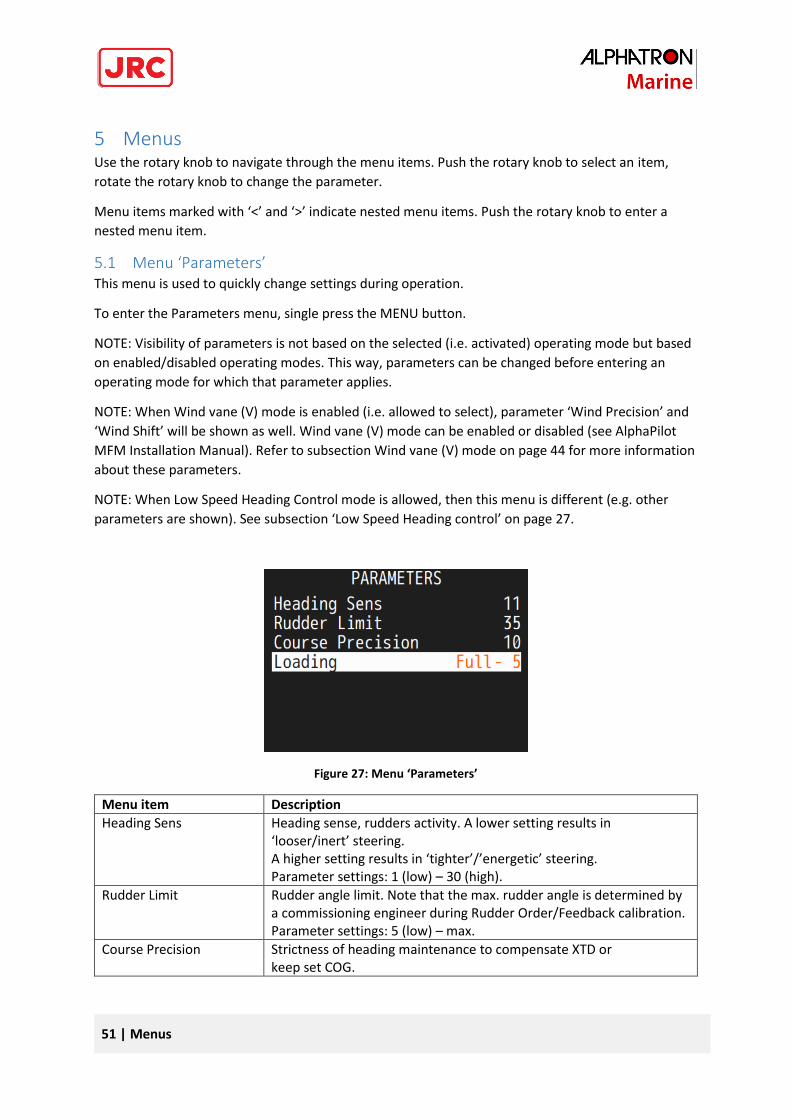
51 | Menus
5 Menus Use the rotary knob to navigate through the menu items. Push the rotary knob to select an item,
rotate the rotary knob to change the parameter.
Menu items marked with ‘<’ and ‘>’ indicate nested menu items. Push the rotary knob to enter a
nested menu item.
5.1 Menu ‘Parameters’ This menu is used to quickly change settings during operation.
To enter the Parameters menu, single press the MENU button.
NOTE: Visibility of parameters is not based on the selected (i.e. activated) operating mode but based
on enabled/disabled operating modes. This way, parameters can be changed before entering an
operating mode for which that parameter applies.
NOTE: When Wind vane (V) mode is enabled (i.e. allowed to select), parameter ‘Wind Precision’ and
‘Wind Shift’ will be shown as well. Wind vane (V) mode can be enabled or disabled (see AlphaPilot
MFM Installation Manual). Refer to subsection Wind vane (V) mode on page 44 for more information
about these parameters.
NOTE: When Low Speed Heading Control mode is allowed, then this menu is different (e.g. other
parameters are shown). See subsection ‘Low Speed Heading control’ on page 27.
Figure 27: Menu ‘Parameters’
Menu item Description
Heading Sens Heading sense, rudders activity. A lower setting results in ‘looser/inert’ steering. A higher setting results in ‘tighter’/’energetic’ steering. Parameter settings: 1 (low) – 30 (high).
Rudder Limit Rudder angle limit. Note that the max. rudder angle is determined by a commissioning engineer during Rudder Order/Feedback calibration. Parameter settings: 5 (low) – max.
Course Precision Strictness of heading maintenance to compensate XTD or keep set COG.
52 | Menus
Menu item Description
This setting is intended for XTD reducing in Track (T) control mode. Vessel heading is corrected more quickly and accurately when this parameter value is increased. This value should be defined depending on the weather conditions and voyage area during voyage in the Track (T) control mode. For example, the ‘Course Precision’ value for the ocean voyages may be set to 10 or smaller. Parameter settings: 1 (low) – 30 (high). NOTE: This parameter will be shown when a Track (T) control mode or CTS pilot (C) control mode is enabled (i.e. allowed to select). The modes can be enabled or disabled (see AlphaPilot MFM Installation Manual).
Loading Parameter to compensate for the change in manoeuvrability of the ship depending on the draft of the vessel. Examples: - Menu shows ‘Ballast 0 .. +5’: Autotuning of the vessel was carried out in ballast. Difference in draft can be set from 0 to +5 meters. - Menu shows ‘Half -5 .. +5’: Autotuning of the vessel was carried out half loaded. Difference in draft can be set from -5 to +5 meters. - Menu shows ‘Full -5 .. 0’: Autotuning of the vessel was carried out fully loaded. Difference in draft can be set from 0 to -5 meters. NOTE: The exact value of the parameter is determined by the crew for the best stability of heading and may not coincide with the real one. NOTE: This parameter will be shown when configured as a vessel with highly variable draft depending on loading.
Press the MENU button to exit the menu.
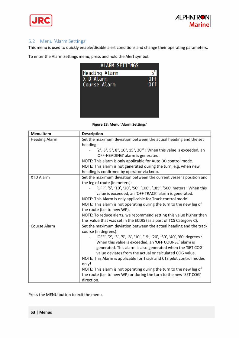
53 | Menus
5.2 Menu ‘Alarm Settings’ This menu is used to quickly enable/disable alert conditions and change their operating parameters.
To enter the Alarm Settings menu, press and hold the Alert symbol.
Figure 28: Menu ‘Alarm Settings’
Menu item Description
Heading Alarm Set the maximum deviation between the actual heading and the set heading:
- ‘2°, 3°, 5°, 8°, 10°, 15°, 20°’ : When this value is exceeded, an ‘OFF-HEADING’ alarm is generated.
NOTE: This alarm is only applicable for Auto (A) control mode. NOTE: This alarm is not generated during the turn, e.g. when new heading is confirmed by operator via knob.
XTD Alarm Set the maximum deviation between the current vessel’s position and the leg of route (in meters):
- ‘OFF’, ‘5’, ‘10’, ‘20’, ‘50’, ’100’, ‘185’, ‘500’ meters : When this value is exceeded, an ‘OFF TRACK’ alarm is generated.
NOTE: This Alarm is only applicable for Track control mode! NOTE: This alarm is not operating during the turn to the new leg of the route (i.e. to new WP). NOTE: To reduce alerts, we recommend setting this value higher than the value that was set in the ECDIS (as a part of TCS Category C).
Course Alarm Set the maximum deviation between the actual heading and the track course (in degrees):
- ‘OFF’, ‘2’, ‘3’, ‘5’, ‘8’, ‘10’, ‘15’, ‘20’, ‘30’, ‘40’, ‘60’ degrees : When this value is exceeded, an ‘OFF COURSE’ alarm is generated. This alarm is also generated when the ‘SET COG’ value deviates from the actual or calculated COG value.
NOTE: This Alarm is applicable for Track and CTS pilot control modes only! NOTE: This alarm is not operating during the turn to the new leg of the route (i.e. to new WP) or during the turn to the new ‘SET COG’ direction.
Press the MENU button to exit the menu.
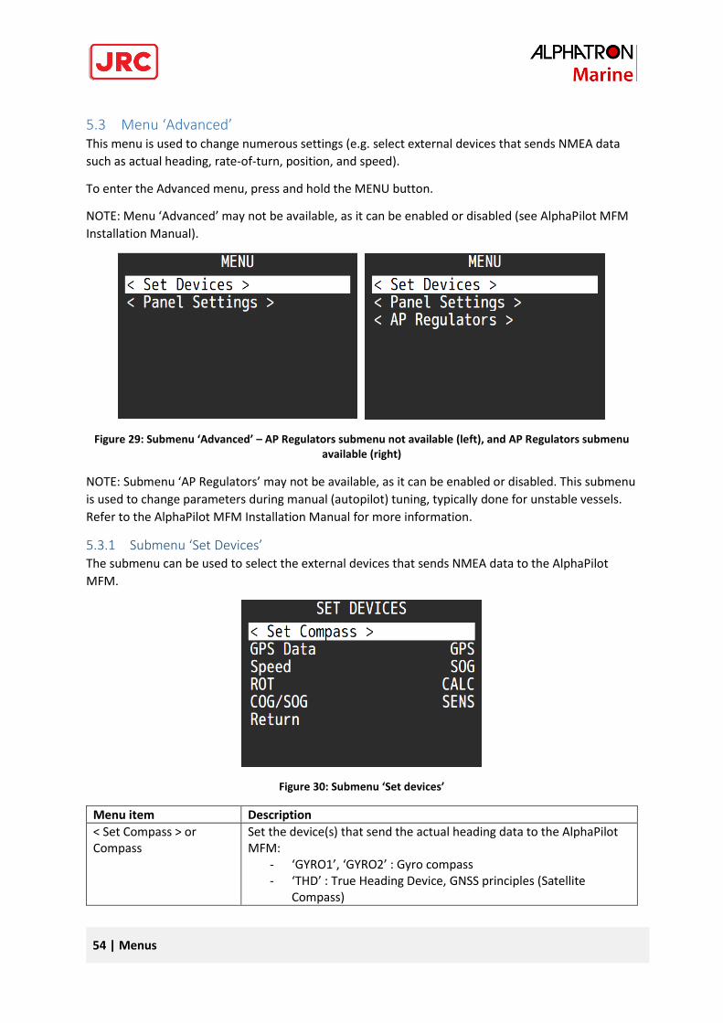
54 | Menus
5.3 Menu ‘Advanced’ This menu is used to change numerous settings (e.g. select external devices that sends NMEA data
such as actual heading, rate-of-turn, position, and speed).
To enter the Advanced menu, press and hold the MENU button.
NOTE: Menu ‘Advanced’ may not be available, as it can be enabled or disabled (see AlphaPilot MFM
Installation Manual).
Figure 29: Submenu ‘Advanced’ – AP Regulators submenu not available (left), and AP Regulators submenu available (right)
NOTE: Submenu ‘AP Regulators’ may not be available, as it can be enabled or disabled. This submenu
is used to change parameters during manual (autopilot) tuning, typically done for unstable vessels.
Refer to the AlphaPilot MFM Installation Manual for more information.
5.3.1 Submenu ‘Set Devices’ The submenu can be used to select the external devices that sends NMEA data to the AlphaPilot
MFM.
Figure 30: Submenu ‘Set devices’
Menu item Description
< Set Compass > or Compass
Set the device(s) that send the actual heading data to the AlphaPilot MFM:
- ‘GYRO1’, ‘GYRO2’ : Gyro compass - ‘THD’ : True Heading Device, GNSS principles (Satellite
Compass)
55 | Menus
Menu item Description
- ‘MAGN’ : Magnetic compass with NMEA output. - ‘HMS ID1’ : ID of the Master Compass from an external HMS
system (ID1 from incoming NMEA HMR sentences). If more than one compass is installed, then a submenu < Set Compass > appears here, instead of ‘Compass’. See next subsection.
GPS Data Set the device that sends vessel position data to the AlphaPilot MFM: - ‘GPS’ : Position data from D-GPS (GGA, GLL NMEA messages). - ‘ECDIS’ : Position data from navigation system (ECDIS/ECS).
NOTE: Position data is used for indication purposes (if GPS/ECDIS is connected to AlphaPilot MFM), and calculation of COG/SOG by incoming GGA, GLL sentences (if VTG sentences are unavailable from GPS/ECDIS). NOTE: Parameter can be changed only in Standby (S) mode.
Speed Set the device that sends vessel speed data to the AlphaPilot MFM: - ‘SOG’ : Speed data from GPS or ECDIS, depending on the
selected item for parameter ‘GPS Data’. - ‘LOG’ : Speed data from Water Speed Log. - ‘ECDIS LOG’ : Speed Through Water data from navigation
system (ECDIS, ECS, INS) by their VHW / VBW NMEA output. - ‘0 to 40’ : Manual speed setting, in knots (not preferred).
NOTE: Speed source can be changed only in Standby (S) mode, except for manual speed setting (‘0 to 40’) (can be used for some heading control modes (e.g. for Auto (A), Dodge (D), FU Override (O), Rate of Turn (R)). NOTE: Track (T) and CTS pilot (C) control modes require a real speed source.
ROT Set the source that sends vessel speed data to the AlphaPilot MFM: - ‘SENS’ : ROT data from an external ROT NMEA sensor. - ‘CALC’ : Calculated ROT data. Calculation based on the
information from primary heading source (e.g. master gyro compass).
NOTE: Only calculated ROT data is used for internal heading adaptive algorithm. This setting is only for the ROT presentation and operation in the Rate of Turn (R) control mode.
COG/SOG Select the source that sends COG and SOG data to the AlphaPilot MFM:
- ‘SENS’ : COG-SOG data from an external GPS sensor or ECDIS. - ‘CALC’ : Calculated COG-SOG data. Calculation based on the
position information from GPS or ECDIS (Latitude and Longitude)
NOTE: Only calculated COG-SOG data is used for internal course adaptive algorithm. This setting is only intended for the COG-SOG presentation on the AlphaPilot MFM control unit and operation in corresponding control modes (e.g. CTS pilot (C) control mode).
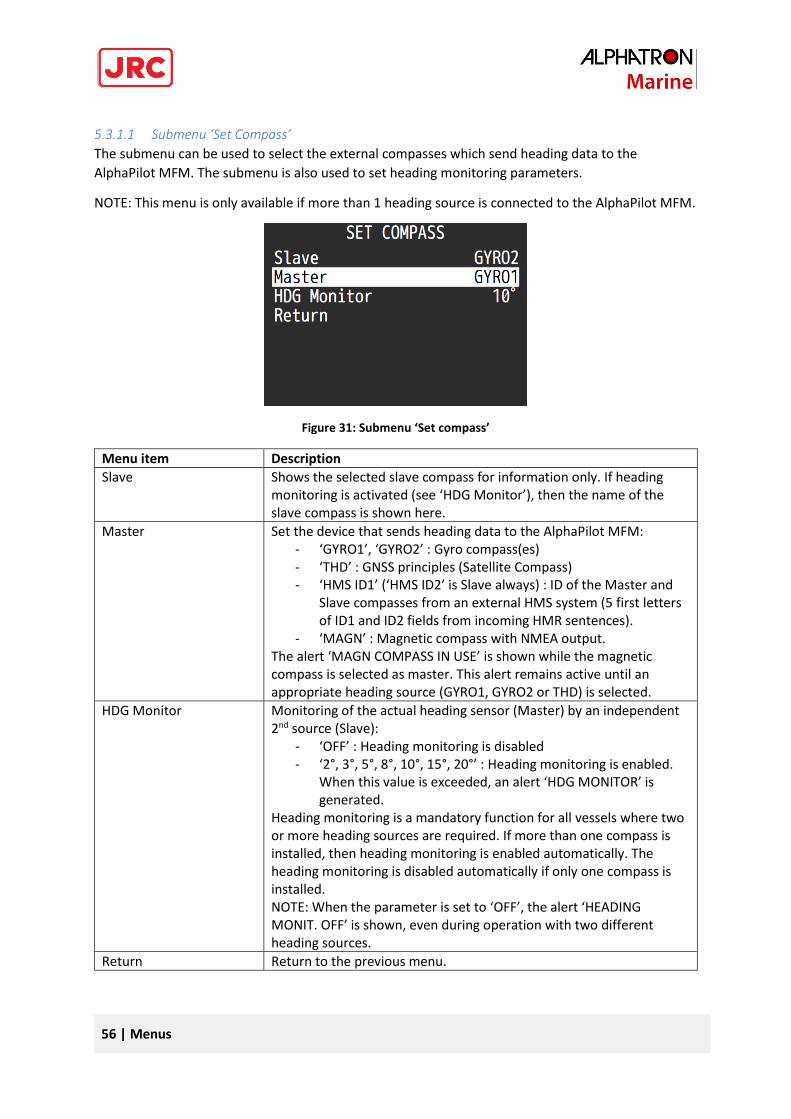
56 | Menus
5.3.1.1 Submenu ‘Set Compass’
The submenu can be used to select the external compasses which send heading data to the
AlphaPilot MFM. The submenu is also used to set heading monitoring parameters.
NOTE: This menu is only available if more than 1 heading source is connected to the AlphaPilot MFM.
Figure 31: Submenu ‘Set compass’
Menu item Description
Slave Shows the selected slave compass for information only. If heading monitoring is activated (see ‘HDG Monitor’), then the name of the slave compass is shown here.
Master Set the device that sends heading data to the AlphaPilot MFM: - ‘GYRO1’, ‘GYRO2’ : Gyro compass(es) - ‘THD’ : GNSS principles (Satellite Compass) - ‘HMS ID1’ (‘HMS ID2’ is Slave always) : ID of the Master and
Slave compasses from an external HMS system (5 first letters of ID1 and ID2 fields from incoming HMR sentences).
- ‘MAGN’ : Magnetic compass with NMEA output. The alert ‘MAGN COMPASS IN USE’ is shown while the magnetic compass is selected as master. This alert remains active until an appropriate heading source (GYRO1, GYRO2 or THD) is selected.
HDG Monitor Monitoring of the actual heading sensor (Master) by an independent 2nd source (Slave):
- ‘OFF’ : Heading monitoring is disabled - ‘2°, 3°, 5°, 8°, 10°, 15°, 20°’ : Heading monitoring is enabled.
When this value is exceeded, an alert ‘HDG MONITOR’ is generated.
Heading monitoring is a mandatory function for all vessels where two or more heading sources are required. If more than one compass is installed, then heading monitoring is enabled automatically. The heading monitoring is disabled automatically if only one compass is installed. NOTE: When the parameter is set to ‘OFF’, the alert ‘HEADING MONIT. OFF’ is shown, even during operation with two different heading sources.
Return Return to the previous menu.
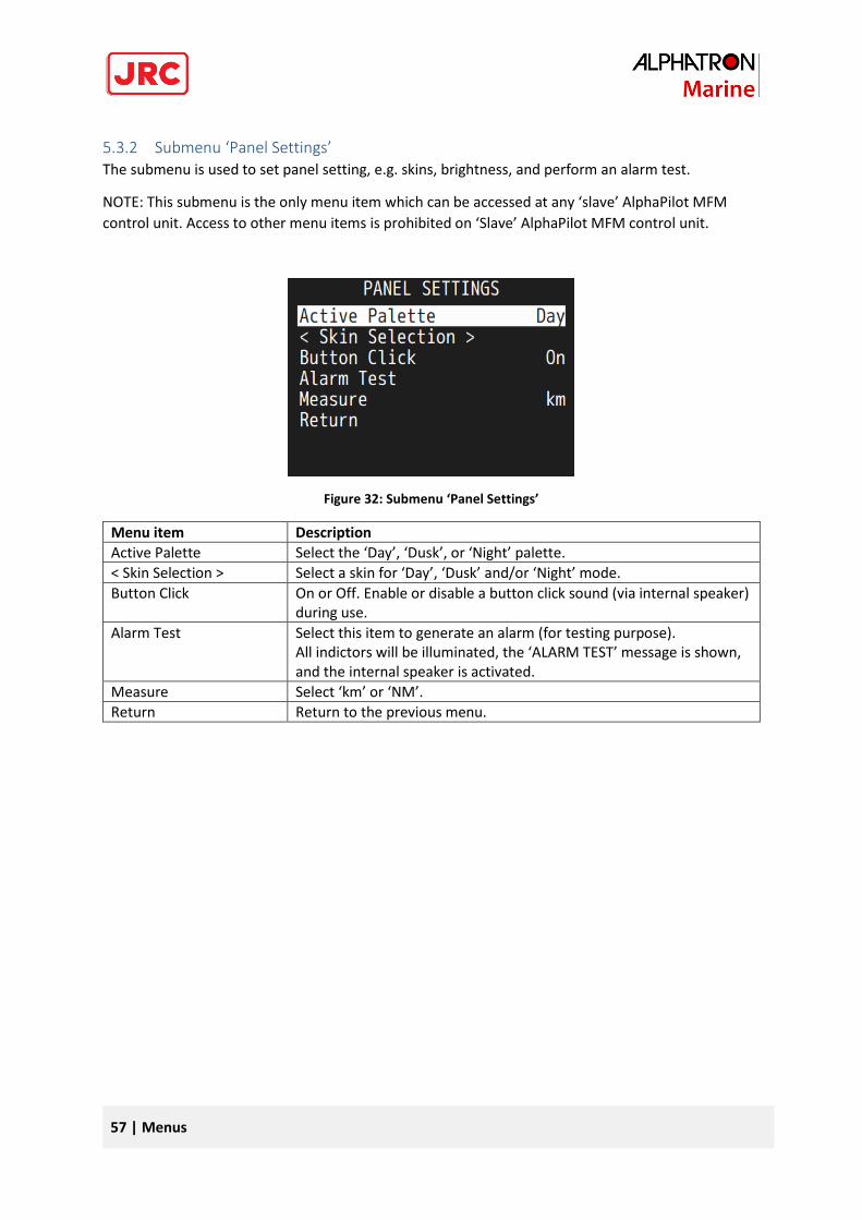
57 | Menus
5.3.2 Submenu ‘Panel Settings’ The submenu is used to set panel setting, e.g. skins, brightness, and perform an alarm test.
NOTE: This submenu is the only menu item which can be accessed at any ‘slave’ AlphaPilot MFM
control unit. Access to other menu items is prohibited on ‘Slave’ AlphaPilot MFM control unit.
Figure 32: Submenu ‘Panel Settings’
Menu item Description
Active Palette Select the ‘Day’, ‘Dusk’, or ‘Night’ palette.
< Skin Selection > Select a skin for ‘Day’, ‘Dusk’ and/or ‘Night’ mode.
Button Click On or Off. Enable or disable a button click sound (via internal speaker) during use.
Alarm Test Select this item to generate an alarm (for testing purpose). All indictors will be illuminated, the ‘ALARM TEST’ message is shown, and the internal speaker is activated.
Measure Select ‘km’ or ‘NM’.
Return Return to the previous menu.
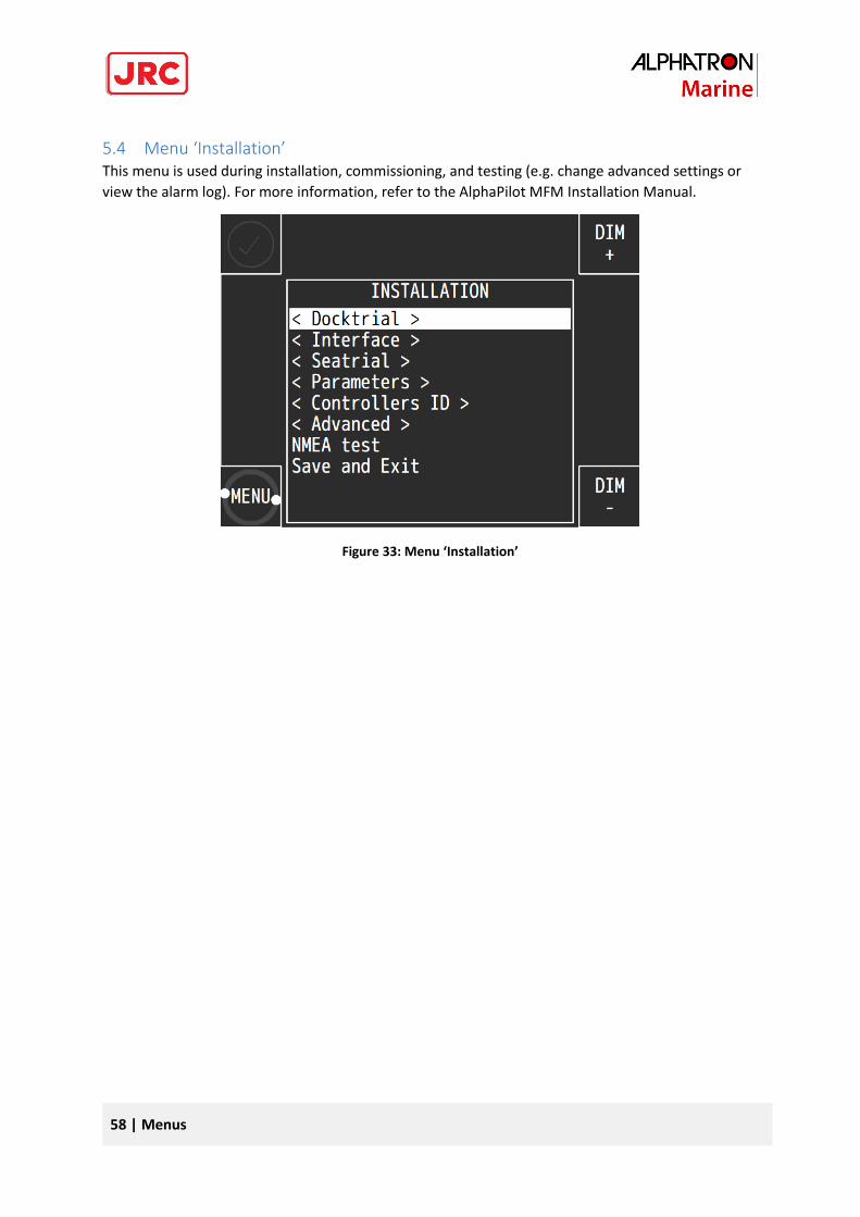
58 | Menus
5.4 Menu ‘Installation’ This menu is used during installation, commissioning, and testing (e.g. change advanced settings or
view the alarm log). For more information, refer to the AlphaPilot MFM Installation Manual.
Figure 33: Menu ‘Installation’
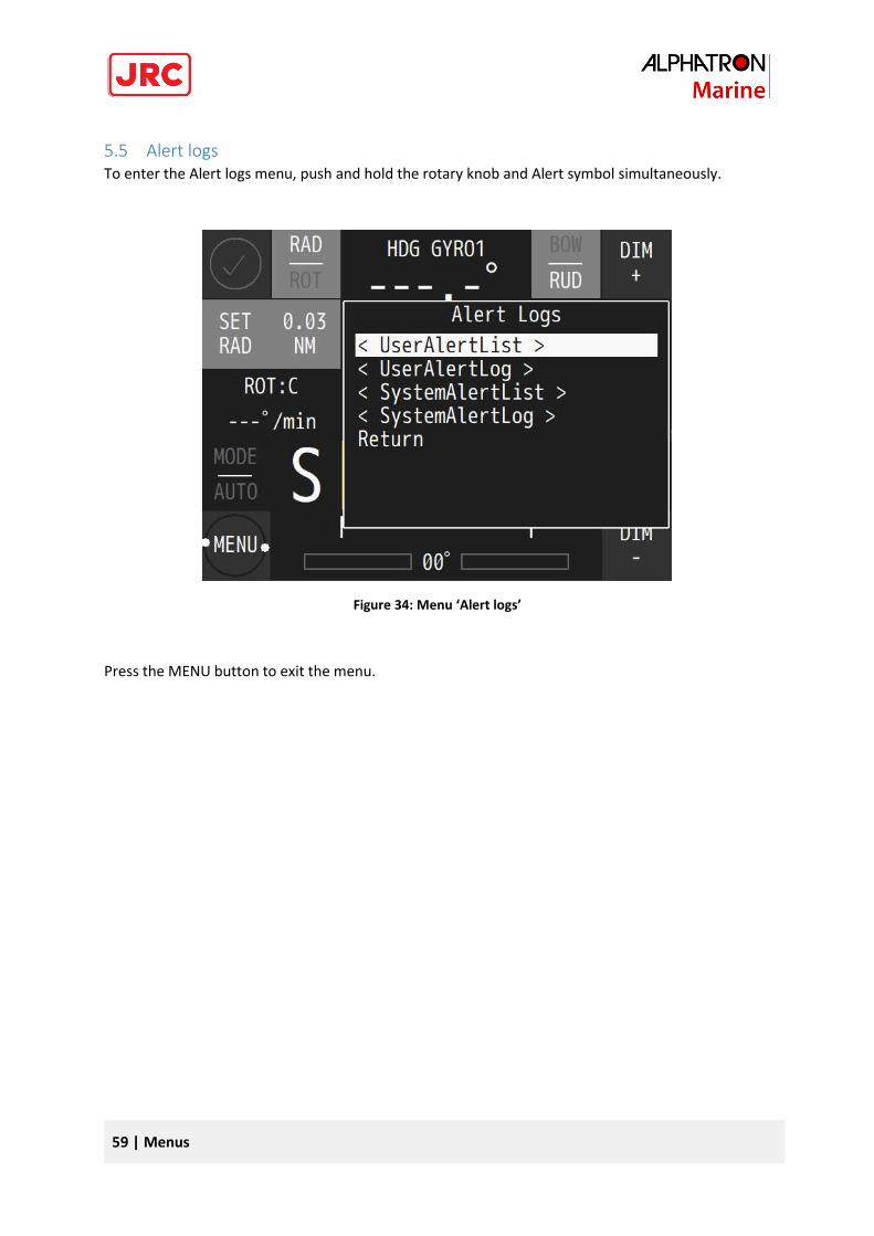
59 | Menus
5.5 Alert logs To enter the Alert logs menu, push and hold the rotary knob and Alert symbol simultaneously.
Figure 34: Menu ‘Alert logs’
Press the MENU button to exit the menu.
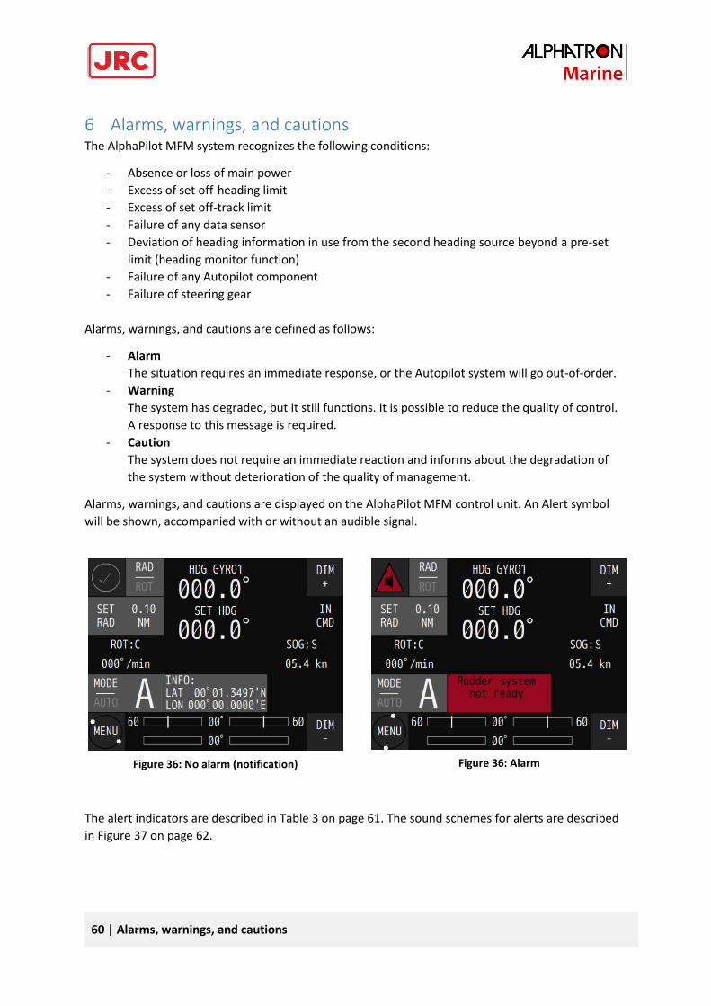
60 | Alarms, warnings, and cautions
6 Alarms, warnings, and cautions The AlphaPilot MFM system recognizes the following conditions:
- Absence or loss of main power
- Excess of set off-heading limit
- Excess of set off-track limit
- Failure of any data sensor
- Deviation of heading information in use from the second heading source beyond a pre-set
limit (heading monitor function)
- Failure of any Autopilot component
- Failure of steering gear
Alarms, warnings, and cautions are defined as follows:
- Alarm
The situation requires an immediate response, or the Autopilot system will go out-of-order.
- Warning
The system has degraded, but it still functions. It is possible to reduce the quality of control.
A response to this message is required.
- Caution
The system does not require an immediate reaction and informs about the degradation of
the system without deterioration of the quality of management.
Alarms, warnings, and cautions are displayed on the AlphaPilot MFM control unit. An Alert symbol
will be shown, accompanied with or without an audible signal.
The alert indicators are described in Table 3 on page 61. The sound schemes for alerts are described
in Figure 37 on page 62.
Figure 36: No alarm (notification) Figure 36: Alarm
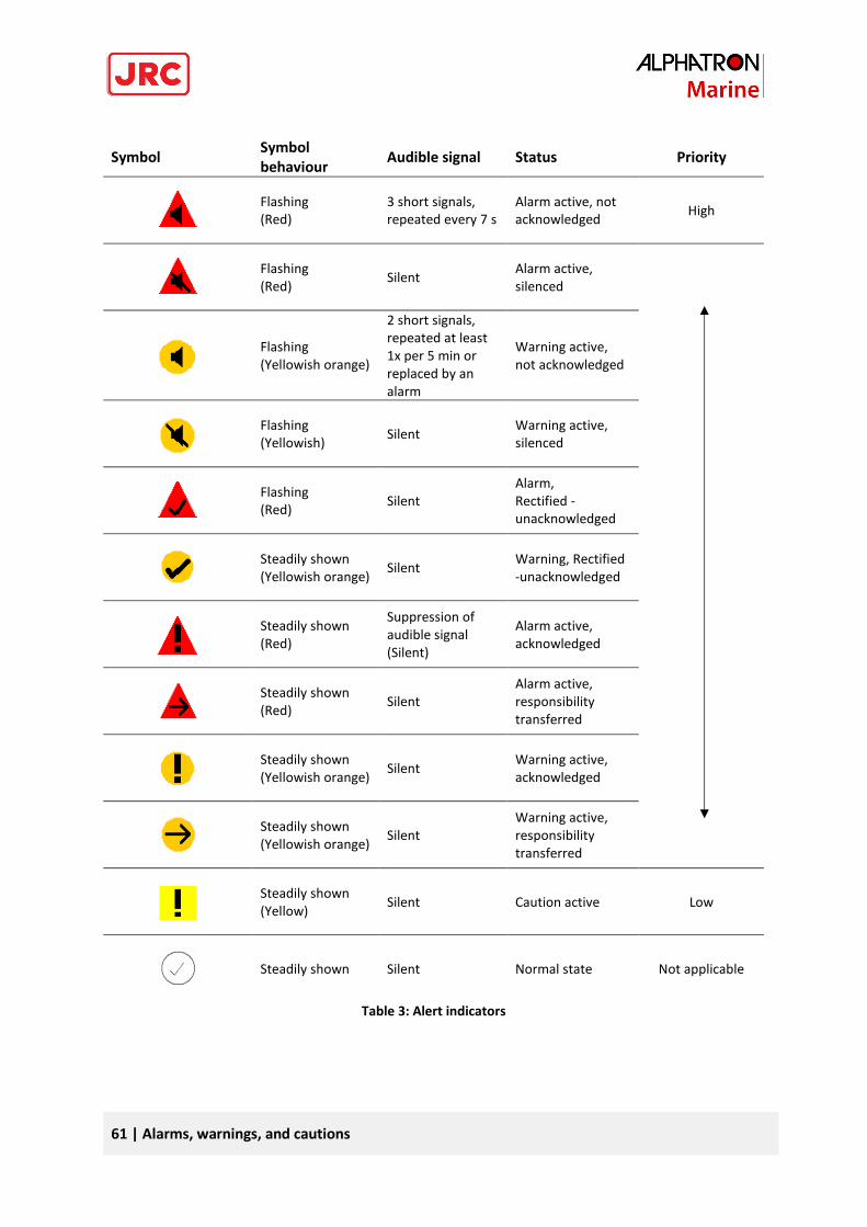
61 | Alarms, warnings, and cautions
Symbol Symbol behaviour
Audible signal Status Priority
Flashing (Red)
3 short signals, repeated every 7 s
Alarm active, not acknowledged
High
Flashing (Red)
Silent Alarm active, silenced
Flashing (Yellowish orange)
2 short signals, repeated at least 1x per 5 min or replaced by an alarm
Warning active, not acknowledged
Flashing (Yellowish)
Silent Warning active, silenced
Flashing (Red)
Silent Alarm, Rectified -unacknowledged
Steadily shown (Yellowish orange)
Silent Warning, Rectified -unacknowledged
Steadily shown (Red)
Suppression of audible signal (Silent)
Alarm active, acknowledged
Steadily shown (Red)
Silent Alarm active, responsibility transferred
Steadily shown (Yellowish orange)
Silent Warning active, acknowledged
Steadily shown (Yellowish orange)
Silent Warning active, responsibility transferred
Steadily shown (Yellow)
Silent Caution active Low
Steadily shown Silent Normal state Not applicable
Table 3: Alert indicators
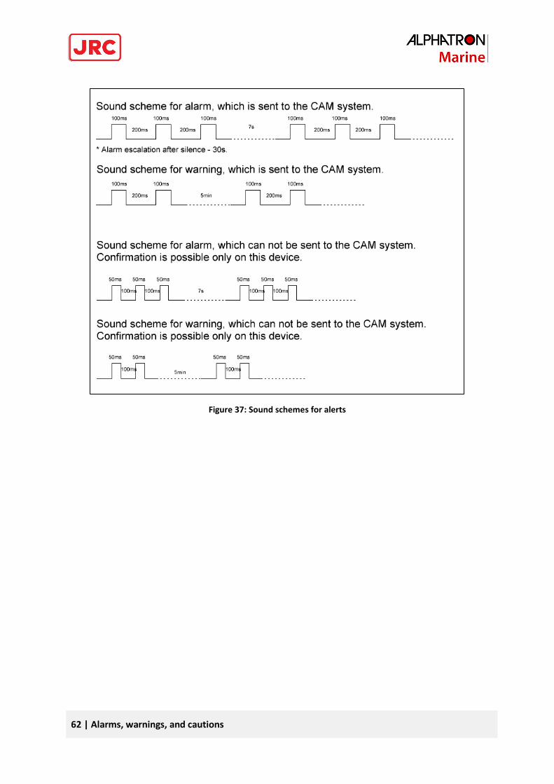
62 | Alarms, warnings, and cautions
Figure 37: Sound schemes for alerts
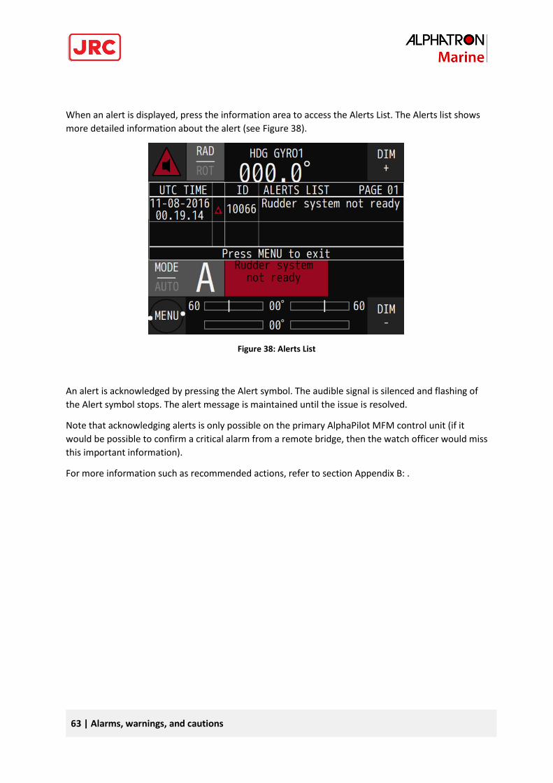
63 | Alarms, warnings, and cautions
When an alert is displayed, press the information area to access the Alerts List. The Alerts list shows
more detailed information about the alert (see Figure 38).
Figure 38: Alerts List
An alert is acknowledged by pressing the Alert symbol. The audible signal is silenced and flashing of
the Alert symbol stops. The alert message is maintained until the issue is resolved.
Note that acknowledging alerts is only possible on the primary AlphaPilot MFM control unit (if it
would be possible to confirm a critical alarm from a remote bridge, then the watch officer would miss
this important information).
For more information such as recommended actions, refer to section Appendix B: .
64 | Troubleshooting
7 Troubleshooting When an abnormal condition has arisen, then the autopilot generates an audible alert, and an alert
message is displayed on the AlphaPilot MFM control unit. Press the information area to access the
Alerts list. The Alerts list shows more detailed information about the alert, such as the Alert ID.
All alerts are listed in Appendix B: Alphatron MFM Alerts.
To view all alerts in the log, see Submenu ‘Alert logs’ on page 59.
If the equipment for some reason does not work as described in this manual, contact the distributor
or dealer, from where the equipment was originally bought. The distributor or dealer will have
experience and know-how to assist with further technical support and troubleshooting.
All information that will get back to Alphatron Marin, either directly or indirectly, will be handled
with confidentiality. End-user sensitive data will not be shared with any third party without prior
written acceptance from the involved parties.
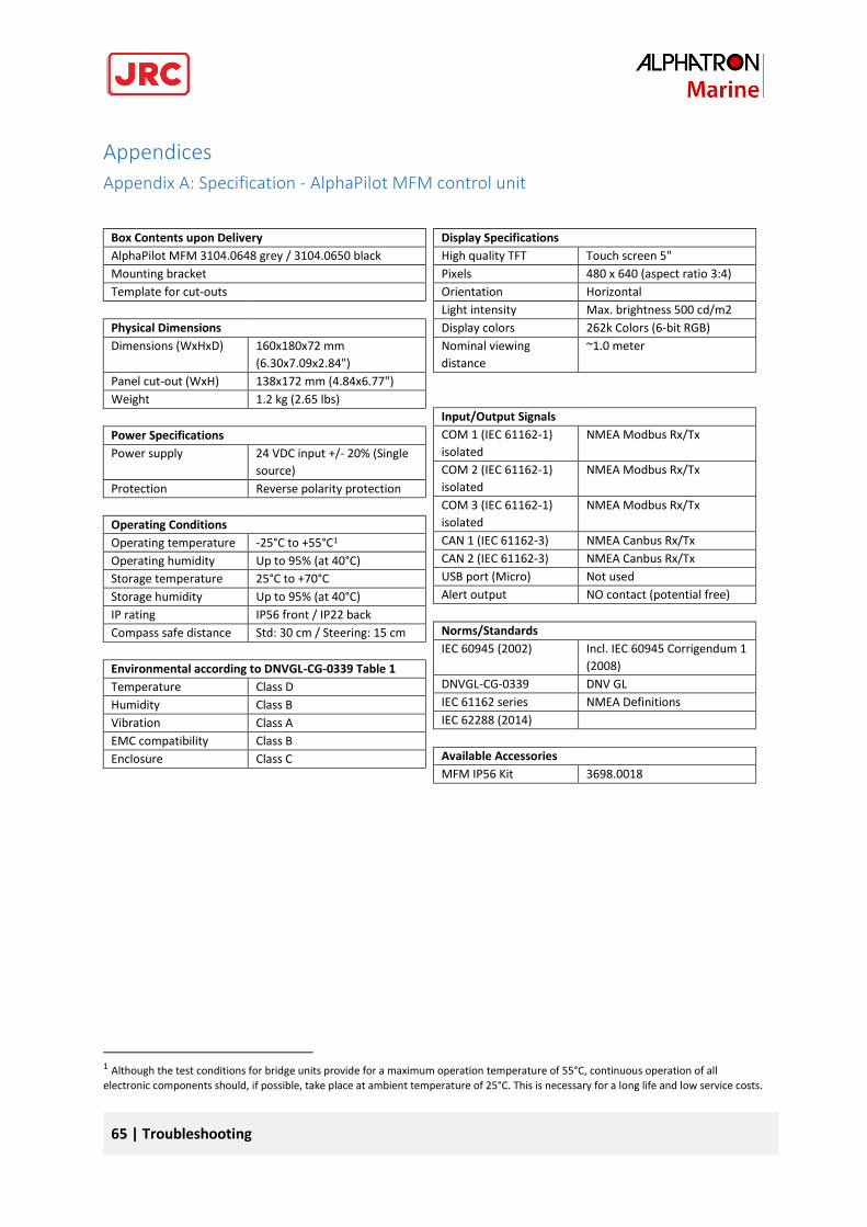
65 | Troubleshooting
Appendices
Appendix A: Specification - AlphaPilot MFM control unit
Box Contents upon Delivery
AlphaPilot MFM 3104.0648 grey / 3104.0650 black
Mounting bracket
Template for cut-outs
Physical Dimensions
Dimensions (WxHxD) 160x180x72 mm
(6.30x7.09x2.84")
Panel cut-out (WxH) 138x172 mm (4.84x6.77")
Weight 1.2 kg (2.65 lbs)
Power Specifications
Power supply 24 VDC input +/- 20% (Single
source)
Protection Reverse polarity protection
Operating Conditions
Operating temperature -25°C to +55°C1
Operating humidity Up to 95% (at 40°C)
Storage temperature 25°C to +70°C
Storage humidity Up to 95% (at 40°C)
IP rating IP56 front / IP22 back
Compass safe distance Std: 30 cm / Steering: 15 cm
Environmental according to DNVGL-CG-0339 Table 1
Temperature Class D
Humidity Class B
Vibration Class A
EMC compatibility Class B
Enclosure Class C
Display Specifications
High quality TFT Touch screen 5"
Pixels 480 x 640 (aspect ratio 3:4)
Orientation Horizontal
Light intensity Max. brightness 500 cd/m2 Display colors 262k Colors (6-bit RGB)
Nominal viewing
distance
~1.0 meter
Input/Output Signals
COM 1 (IEC 61162-1)
isolated
NMEA Modbus Rx/Tx
COM 2 (IEC 61162-1)
isolated
NMEA Modbus Rx/Tx
COM 3 (IEC 61162-1)
isolated
NMEA Modbus Rx/Tx
CAN 1 (IEC 61162-3) NMEA Canbus Rx/Tx
CAN 2 (IEC 61162-3) NMEA Canbus Rx/Tx
USB port (Micro) Not used
Alert output NO contact (potential free)
Norms/Standards
IEC 60945 (2002) Incl. IEC 60945 Corrigendum 1
(2008)
DNVGL-CG-0339 DNV GL
IEC 61162 series NMEA Definitions
IEC 62288 (2014)
Available Accessories
MFM IP56 Kit 3698.0018
1 Although the test conditions for bridge units provide for a maximum operation temperature of 55°C, continuous operation of all
electronic components should, if possible, take place at ambient temperature of 25°C. This is necessary for a long life and low service costs.
66 | Troubleshooting
Appendix B: Alphatron MFM Alerts
Communication with CAM and local indication.
Work modes as abbreviated in this appendix are:
• Standby (STBY) mode
• Auto (AUTO) heading control mode
• Track (TC) control mode (Category A, B or C depending on configuration)
• Course control (CC) mode
• Temporary Override to FU Tiller or wheel (FFU)
• Temporary Override to FU Tiller (OVR)
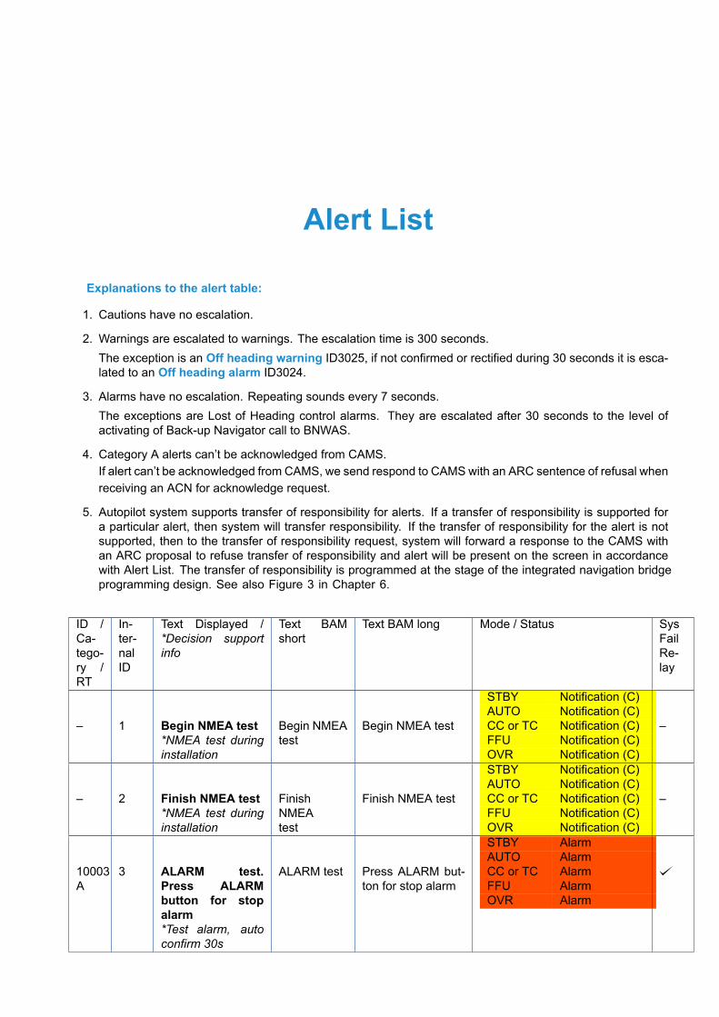
Alert List
Explanations to the alert table:
1. Cautions have no escalation.
2. Warnings are escalated to warnings. The escalation time is 300 seconds.The exception is an Off heading warning ID3025, if not confirmed or rectified during 30 seconds it is esca-lated to an Off heading alarm ID3024.
3. Alarms have no escalation. Repeating sounds every 7 seconds.The exceptions are Lost of Heading control alarms. They are escalated after 30 seconds to the level ofactivating of Back-up Navigator call to BNWAS.
4. Category A alerts can’t be acknowledged from CAMS.If alert can’t be acknowledged from CAMS, we send respond to CAMS with an ARC sentence of refusal whenreceiving an ACN for acknowledge request.
5. Autopilot system supports transfer of responsibility for alerts. If a transfer of responsibility is supported fora particular alert, then system will transfer responsibility. If the transfer of responsibility for the alert is notsupported, then to the transfer of responsibility request, system will forward a response to the CAMS withan ARC proposal to refuse transfer of responsibility and alert will be present on the screen in accordancewith Alert List. The transfer of responsibility is programmed at the stage of the integrated navigation bridgeprogramming design. See also Figure 3 in Chapter 6.
ID /Ca-tego-ry /RT
In-ter-nalID
Text Displayed /*Decision supportinfo
Text BAMshort
Text BAM long Mode / Status SysFailRe-lay
– 1 Begin NMEA test*NMEA test duringinstallation
Begin NMEAtest
Begin NMEA test
STBY Notification (C)AUTO Notification (C)CC or TC Notification (C)FFU Notification (C)OVR Notification (C)
–
– 2 Finish NMEA test*NMEA test duringinstallation
FinishNMEAtest
Finish NMEA test
STBY Notification (C)AUTO Notification (C)CC or TC Notification (C)FFU Notification (C)OVR Notification (C)
–
10003A
3 ALARM test.Press ALARMbutton for stopalarm*Test alarm, autoconfirm 30s
ALARM test Press ALARM but-ton for stop alarm
STBY AlarmAUTO AlarmCC or TC AlarmFFU AlarmOVR Alarm
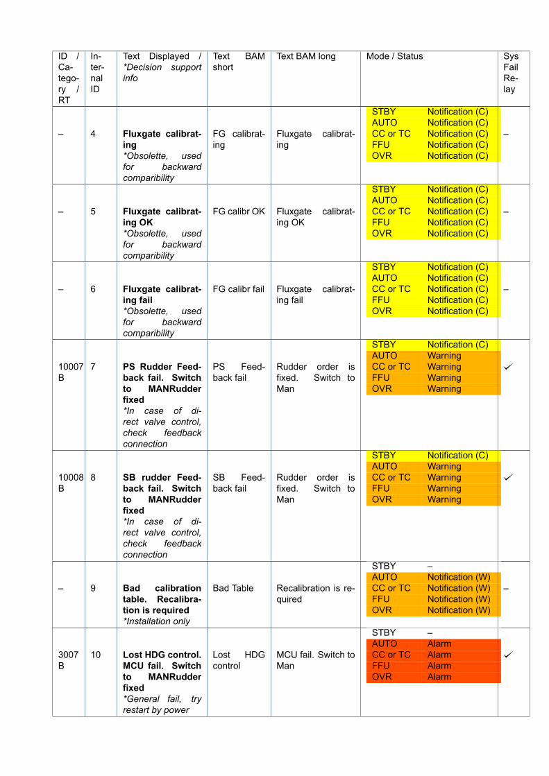
ID /Ca-tego-ry /RT
In-ter-nalID
Text Displayed /*Decision supportinfo
Text BAMshort
Text BAM long Mode / Status SysFailRe-lay
– 4 Fluxgate calibrat-ing*Obsolette, usedfor backwardcomparibility
FG calibrat-ing
Fluxgate calibrat-ing
STBY Notification (C)AUTO Notification (C)CC or TC Notification (C)FFU Notification (C)OVR Notification (C)
–
– 5 Fluxgate calibrat-ing OK*Obsolette, usedfor backwardcomparibility
FG calibr OK Fluxgate calibrat-ing OK
STBY Notification (C)AUTO Notification (C)CC or TC Notification (C)FFU Notification (C)OVR Notification (C)
–
– 6 Fluxgate calibrat-ing fail*Obsolette, usedfor backwardcomparibility
FG calibr fail Fluxgate calibrat-ing fail
STBY Notification (C)AUTO Notification (C)CC or TC Notification (C)FFU Notification (C)OVR Notification (C)
–
10007B
7 PS Rudder Feed-back fail. Switchto MANRudderfixed*In case of di-rect valve control,check feedbackconnection
PS Feed-back fail
Rudder order isfixed. Switch toMan
STBY Notification (C)AUTO WarningCC or TC WarningFFU WarningOVR Warning
10008B
8 SB rudder Feed-back fail. Switchto MANRudderfixed*In case of di-rect valve control,check feedbackconnection
SB Feed-back fail
Rudder order isfixed. Switch toMan
STBY Notification (C)AUTO WarningCC or TC WarningFFU WarningOVR Warning
– 9 Bad calibrationtable. Recalibra-tion is required*Installation only
Bad Table Recalibration is re-quired
STBY –AUTO Notification (W)CC or TC Notification (W)FFU Notification (W)OVR Notification (W)
–
3007B
10 Lost HDG control.MCU fail. Switchto MANRudderfixed*General fail, tryrestart by power
Lost HDGcontrol
MCU fail. Switch toMan
STBY –AUTO AlarmCC or TC AlarmFFU AlarmOVR Alarm
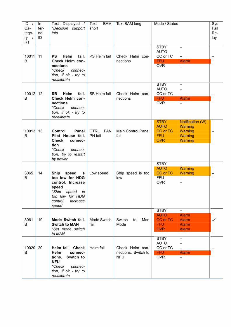
ID /Ca-tego-ry /RT
In-ter-nalID
Text Displayed /*Decision supportinfo
Text BAMshort
Text BAM long Mode / Status SysFailRe-lay
10011B
11 PS Helm fail.Check Helm con-nections*Check connec-tion, if ok - try torecalibrate
PS Helm fail Check Helm con-nections
STBY –AUTO –CC or TC –FFU AlarmOVR –
–
10012B
12 SB Helm fail.Check Helm con-nections*Check connec-tion, if ok - try torecalibrate
SB Helm fail Check Helm con-nections
STBY –AUTO –CC or TC –FFU AlarmOVR –
–
10013B
13 Control PanelPilot House fail.Check connec-tion*Check connec-tion, try to restartby power
CTRL PANPH fail
Main Control Panelfail
STBY Notification (W)AUTO WarningCC or TC WarningFFU WarningOVR Warning
–
3065B
14 Ship speed istoo low for HDGcontrol. Increasespeed*Ship speed istoo low for HDGcontrol. Increasespeed
Low speed Ship speed is toolow
STBY –AUTO WarningCC or TC WarningFFU –OVR –
–
3061B
19 Mode Switch fail.Switch to MAN*Set mode switchto MAN
Mode Switchfail
Switch to ManMode
STBY –AUTO AlarmCC or TC AlarmFFU AlarmOVR Alarm
10020B
20 Helm fail. CheckHelm connec-tions. Switch toNFU*Check connec-tion, if ok - try torecalibrate
Helm fail Check Helm con-nections. Switch toNFU
STBY –AUTO –CC or TC –FFU AlarmOVR –
–
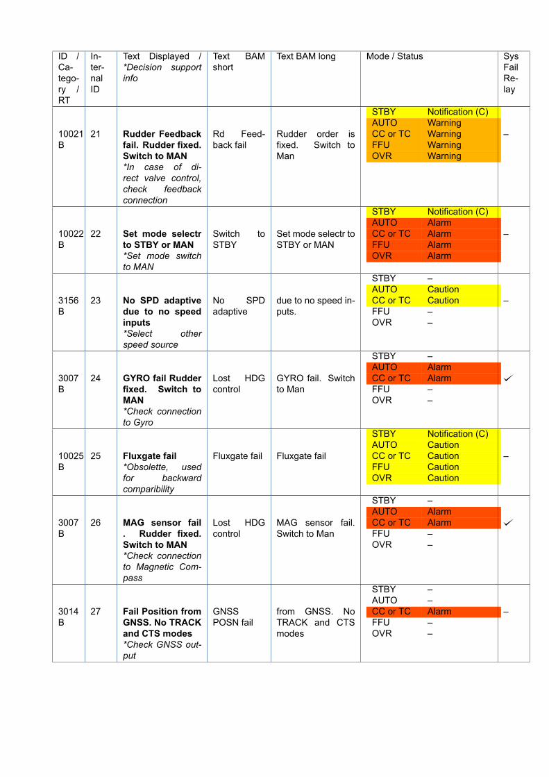
ID /Ca-tego-ry /RT
In-ter-nalID
Text Displayed /*Decision supportinfo
Text BAMshort
Text BAM long Mode / Status SysFailRe-lay
10021B
21 Rudder Feedbackfail. Rudder fixed.Switch to MAN*In case of di-rect valve control,check feedbackconnection
Rd Feed-back fail
Rudder order isfixed. Switch toMan
STBY Notification (C)AUTO WarningCC or TC WarningFFU WarningOVR Warning
–
10022B
22 Set mode selectrto STBY or MAN*Set mode switchto MAN
Switch toSTBY
Set mode selectr toSTBY or MAN
STBY Notification (C)AUTO AlarmCC or TC AlarmFFU AlarmOVR Alarm
–
3156B
23 No SPD adaptivedue to no speedinputs*Select otherspeed source
No SPDadaptive
due to no speed in-puts.
STBY –AUTO CautionCC or TC CautionFFU –OVR –
–
3007B
24 GYRO fail Rudderfixed. Switch toMAN*Check connectionto Gyro
Lost HDGcontrol
GYRO fail. Switchto Man
STBY –AUTO AlarmCC or TC AlarmFFU –OVR –
10025B
25 Fluxgate fail*Obsolette, usedfor backwardcomparibility
Fluxgate fail Fluxgate fail
STBY Notification (C)AUTO CautionCC or TC CautionFFU CautionOVR Caution
–
3007B
26 MAG sensor fail. Rudder fixed.Switch to MAN*Check connectionto Magnetic Com-pass
Lost HDGcontrol
MAG sensor fail.Switch to Man
STBY –AUTO AlarmCC or TC AlarmFFU –OVR –
3014B
27 Fail Position fromGNSS. No TRACKand CTS modes*Check GNSS out-put
GNSSPOSN fail
from GNSS. NoTRACK and CTSmodes
STBY –AUTO –CC or TC AlarmFFU –OVR –
–
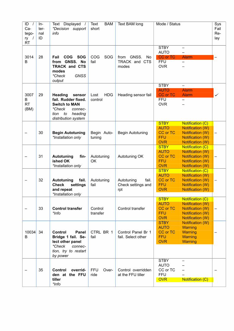
ID /Ca-tego-ry /RT
In-ter-nalID
Text Displayed /*Decision supportinfo
Text BAMshort
Text BAM long Mode / Status SysFailRe-lay
3014B
28 Fail COG SOGfrom GNSS. NoTRACK and CTSmodes*Check GNSSoutput
COG SOGfail
from GNSS. NoTRACK and CTSmodes
STBY –AUTO –CC or TC AlarmFFU –OVR –
–
3007BRT(BM)
29 Heading sensorfail. Rudder fixed.Switch to MAN*Check connec-tion to headingdistribution system
Lost HDGcontrol
Heading sensor fail
STBY –AUTO AlarmCC or TC AlarmFFU –OVR –
– 30 Begin Autotuning*Installation only
Begin Auto-tuning
Begin Autotuning
STBY Notification (C)AUTO Notification (W)CC or TC Notification (W)FFU Notification (W)OVR Notification (W)
–
– 31 Autotuning fin-ished OK*Installation only
AutotuningOK
Autotuning OK
STBY Notification (C)AUTO Notification (W)CC or TC Notification (W)FFU Notification (W)OVR Notification (W)
–
– 32 Autotuning fail.Check settingsand repeat*Installation only
Autotuningfail
Autotuning fail.Check settings andrpt
STBY Notification (C)AUTO Notification (W)CC or TC Notification (W)FFU Notification (W)OVR Notification (W)
–
– 33 Control transfer*Info
Controltransfer
Control transfer
STBY Notification (C)AUTO Notification (W)CC or TC Notification (W)FFU Notification (W)OVR Notification (W)
–
10034B
34 Control PanelBridge 1 fail. Se-lect other panel*Check connec-tion, try to restartby power
CTRL BR 1fail
Control Panel Br 1fail. Select other
STBY Notification (W)AUTO WarningCC or TC WarningFFU WarningOVR Warning
–
– 35 Control overrid-den at the FFUtiller*Info
FFU Over-ride
Control overriddenat the FFU tiller
STBY –AUTO –CC or TC –FFU –OVR Notification (C)
–
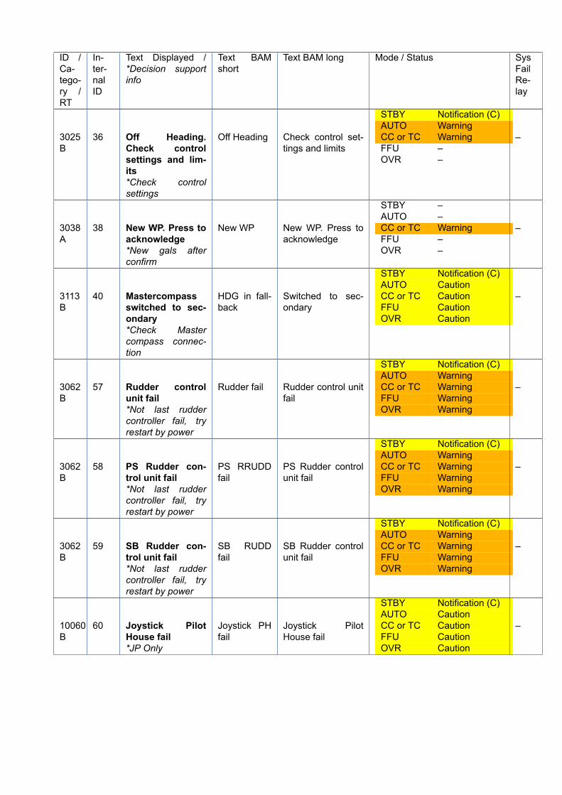
ID /Ca-tego-ry /RT
In-ter-nalID
Text Displayed /*Decision supportinfo
Text BAMshort
Text BAM long Mode / Status SysFailRe-lay
3025B
36 Off Heading.Check controlsettings and lim-its*Check controlsettings
Off Heading Check control set-tings and limits
STBY Notification (C)AUTO WarningCC or TC WarningFFU –OVR –
–
3038A
38 New WP. Press toacknowledge*New gals afterconfirm
New WP New WP. Press toacknowledge
STBY –AUTO –CC or TC WarningFFU –OVR –
–
3113B
40 Mastercompassswitched to sec-ondary*Check Mastercompass connec-tion
HDG in fall-back
Switched to sec-ondary
STBY Notification (C)AUTO CautionCC or TC CautionFFU CautionOVR Caution
–
3062B
57 Rudder controlunit fail*Not last ruddercontroller fail, tryrestart by power
Rudder fail Rudder control unitfail
STBY Notification (C)AUTO WarningCC or TC WarningFFU WarningOVR Warning
–
3062B
58 PS Rudder con-trol unit fail*Not last ruddercontroller fail, tryrestart by power
PS RRUDDfail
PS Rudder controlunit fail
STBY Notification (C)AUTO WarningCC or TC WarningFFU WarningOVR Warning
–
3062B
59 SB Rudder con-trol unit fail*Not last ruddercontroller fail, tryrestart by power
SB RUDDfail
SB Rudder controlunit fail
STBY Notification (C)AUTO WarningCC or TC WarningFFU WarningOVR Warning
–
10060B
60 Joystick PilotHouse fail*JP Only
Joystick PHfail
Joystick PilotHouse fail
STBY Notification (C)AUTO CautionCC or TC CautionFFU CautionOVR Caution
–
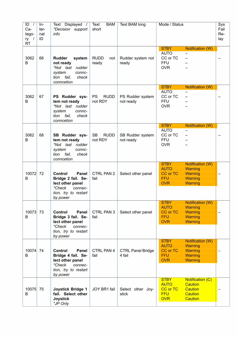
ID /Ca-tego-ry /RT
In-ter-nalID
Text Displayed /*Decision supportinfo
Text BAMshort
Text BAM long Mode / Status SysFailRe-lay
3062B
66 Rudder systemnot ready*Not last ruddersystem connc-tion fail, checkconncetion
RUDD notready
Rudder system notready
STBY Notification (W)AUTO –CC or TC –FFU –OVR –
–
3062B
67 PS Rudder sys-tem not ready*Not last ruddersystem connc-tion fail, checkconncetion
PS RUDDnot RDY
PS Rudder systemnot ready
STBY Notification (W)AUTO –CC or TC –FFU –OVR –
–
3062B
68 SB Rudder sys-tem not ready*Not last ruddersystem connc-tion fail, checkconncetion
SB RUDDnot RDY
SB Rudder systemnot ready
STBY Notification (W)AUTO –CC or TC –FFU –OVR –
–
10072B
72 Control PanelBridge 2 fail. Se-lect other panel*Check connec-tion, try to restartby power
CTRL PAN 2fail
Select other panel
STBY Notification (W)AUTO WarningCC or TC WarningFFU WarningOVR Warning
–
10073B
73 Control PanelBridge 3 fail. Se-lect other panel*Check connec-tion, try to restartby power
CTRL PAN 3fail
Select other panel
STBY Notification (W)AUTO WarningCC or TC WarningFFU WarningOVR Warning
–
10074B
74 Control PanelBridge 4 fail. Se-lect other panel*Check connec-tion, try to restartby power
CTRL PAN 4fail
CTRL Panel Bridge4 fail
STBY Notification (W)AUTO WarningCC or TC WarningFFU WarningOVR Warning
–
10075B
75 Joystick Bridge 1fail. Select otherJoystick*JP Only
JOY BR1 fail Select other Joy-stick
STBY Notification (C)AUTO CautionCC or TC CautionFFU CautionOVR Caution
–
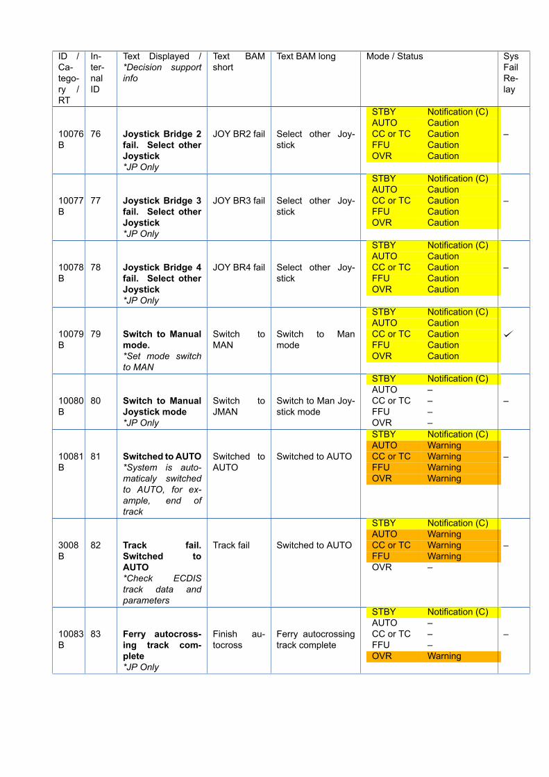
ID /Ca-tego-ry /RT
In-ter-nalID
Text Displayed /*Decision supportinfo
Text BAMshort
Text BAM long Mode / Status SysFailRe-lay
10076B
76 Joystick Bridge 2fail. Select otherJoystick*JP Only
JOY BR2 fail Select other Joy-stick
STBY Notification (C)AUTO CautionCC or TC CautionFFU CautionOVR Caution
–
10077B
77 Joystick Bridge 3fail. Select otherJoystick*JP Only
JOY BR3 fail Select other Joy-stick
STBY Notification (C)AUTO CautionCC or TC CautionFFU CautionOVR Caution
–
10078B
78 Joystick Bridge 4fail. Select otherJoystick*JP Only
JOY BR4 fail Select other Joy-stick
STBY Notification (C)AUTO CautionCC or TC CautionFFU CautionOVR Caution
–
10079B
79 Switch to Manualmode.*Set mode switchto MAN
Switch toMAN
Switch to Manmode
STBY Notification (C)AUTO CautionCC or TC CautionFFU CautionOVR Caution
10080B
80 Switch to ManualJoystick mode*JP Only
Switch toJMAN
Switch to Man Joy-stick mode
STBY Notification (C)AUTO –CC or TC –FFU –OVR –
–
10081B
81 Switched to AUTO*System is auto-maticaly switchedto AUTO, for ex-ample, end oftrack
Switched toAUTO
Switched to AUTO
STBY Notification (C)AUTO WarningCC or TC WarningFFU WarningOVR Warning
–
3008B
82 Track fail.Switched toAUTO*Check ECDIStrack data andparameters
Track fail Switched to AUTO
STBY Notification (C)AUTO WarningCC or TC WarningFFU WarningOVR –
–
10083B
83 Ferry autocross-ing track com-plete*JP Only
Finish au-tocross
Ferry autocrossingtrack complete
STBY Notification (C)AUTO –CC or TC –FFU –OVR Warning
–
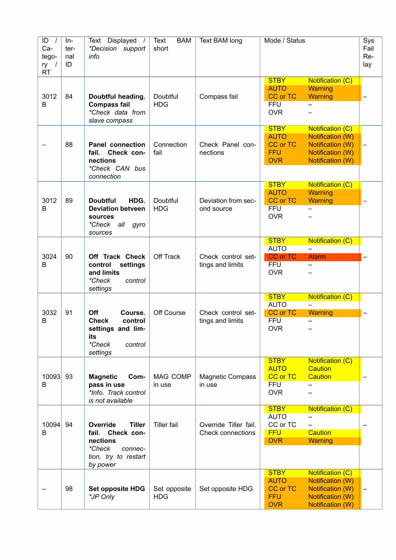
ID /Ca-tego-ry /RT
In-ter-nalID
Text Displayed /*Decision supportinfo
Text BAMshort
Text BAM long Mode / Status SysFailRe-lay
3012B
84 Doubtful heading.Compass fail*Check data fromslave compass
DoubtfulHDG
Compass fail
STBY Notification (C)AUTO WarningCC or TC WarningFFU –OVR –
–
– 88 Panel connectionfail. Check con-nections*Check CAN busconnection
Connectionfail
Check Panel con-nections
STBY Notification (C)AUTO Notification (W)CC or TC Notification (W)FFU Notification (W)OVR Notification (W)
–
3012B
89 Doubtful HDG.Deviation betveensources*Check all gyrosources
DoubtfulHDG
Deviation from sec-ond source
STBY Notification (C)AUTO WarningCC or TC WarningFFU –OVR –
–
3024B
90 Off Track Checkcontrol settingsand limits*Check controlsettings
Off Track Check control set-tings and limits
STBY Notification (C)AUTO –CC or TC AlarmFFU –OVR –
–
3032B
91 Off Course.Check controlsettings and lim-its*Check controlsettings
Off Course Check control set-tings and limits
STBY Notification (C)AUTO –CC or TC WarningFFU –OVR –
–
10093B
93 Magnetic Com-pass in use*Info. Track controlis not available
MAG COMPin use
Magnetic Compassin use
STBY Notification (C)AUTO CautionCC or TC CautionFFU –OVR –
–
10094B
94 Override Tillerfail. Check con-nections*Check connec-tion, try to restartby power
Tiller fail Override Tiller fail.Check connections
STBY Notification (C)AUTO –CC or TC –FFU CautionOVR Warning
–
– 98 Set opposite HDG*JP Only
Set oppositeHDG
Set opposite HDG
STBY Notification (C)AUTO Notification (W)CC or TC Notification (W)FFU Notification (W)OVR Notification (W)
–
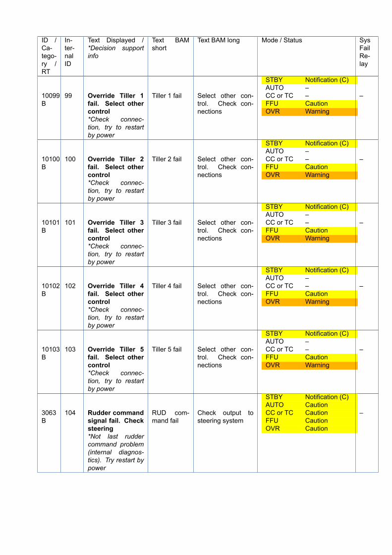
ID /Ca-tego-ry /RT
In-ter-nalID
Text Displayed /*Decision supportinfo
Text BAMshort
Text BAM long Mode / Status SysFailRe-lay
10099B
99 Override Tiller 1fail. Select othercontrol*Check connec-tion, try to restartby power
Tiller 1 fail Select other con-trol. Check con-nections
STBY Notification (C)AUTO –CC or TC –FFU CautionOVR Warning
–
10100B
100 Override Tiller 2fail. Select othercontrol*Check connec-tion, try to restartby power
Tiller 2 fail Select other con-trol. Check con-nections
STBY Notification (C)AUTO –CC or TC –FFU CautionOVR Warning
–
10101B
101 Override Tiller 3fail. Select othercontrol*Check connec-tion, try to restartby power
Tiller 3 fail Select other con-trol. Check con-nections
STBY Notification (C)AUTO –CC or TC –FFU CautionOVR Warning
–
10102B
102 Override Tiller 4fail. Select othercontrol*Check connec-tion, try to restartby power
Tiller 4 fail Select other con-trol. Check con-nections
STBY Notification (C)AUTO –CC or TC –FFU CautionOVR Warning
–
10103B
103 Override Tiller 5fail. Select othercontrol*Check connec-tion, try to restartby power
Tiller 5 fail Select other con-trol. Check con-nections
STBY Notification (C)AUTO –CC or TC –FFU CautionOVR Warning
–
3063B
104 Rudder commandsignal fail. Checksteering*Not last ruddercommand problem(internal diagnos-tics). Try restart bypower
RUD com-mand fail
Check output tosteering system
STBY Notification (C)AUTO CautionCC or TC CautionFFU CautionOVR Caution
–
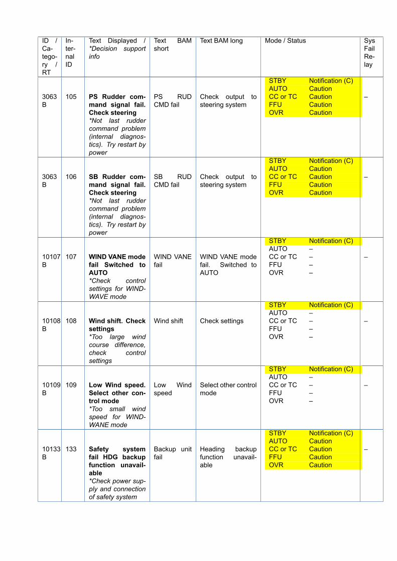
ID /Ca-tego-ry /RT
In-ter-nalID
Text Displayed /*Decision supportinfo
Text BAMshort
Text BAM long Mode / Status SysFailRe-lay
3063B
105 PS Rudder com-mand signal fail.Check steering*Not last ruddercommand problem(internal diagnos-tics). Try restart bypower
PS RUDCMD fail
Check output tosteering system
STBY Notification (C)AUTO CautionCC or TC CautionFFU CautionOVR Caution
–
3063B
106 SB Rudder com-mand signal fail.Check steering*Not last ruddercommand problem(internal diagnos-tics). Try restart bypower
SB RUDCMD fail
Check output tosteering system
STBY Notification (C)AUTO CautionCC or TC CautionFFU CautionOVR Caution
–
10107B
107 WIND VANE modefail Switched toAUTO*Check controlsettings for WIND-WAVE mode
WIND VANEfail
WIND VANE modefail. Switched toAUTO
STBY Notification (C)AUTO –CC or TC –FFU –OVR –
–
10108B
108 Wind shift. Checksettings*Too large windcourse difference,check controlsettings
Wind shift Check settings
STBY Notification (C)AUTO –CC or TC –FFU –OVR –
–
10109B
109 Low Wind speed.Select other con-trol mode*Too small windspeed for WIND-WANE mode
Low Windspeed
Select other controlmode
STBY Notification (C)AUTO –CC or TC –FFU –OVR –
–
10133B
133 Safety systemfail HDG backupfunction unavail-able*Check power sup-ply and connectionof safety system
Backup unitfail
Heading backupfunction unavail-able
STBY Notification (C)AUTO CautionCC or TC CautionFFU CautionOVR Caution
–
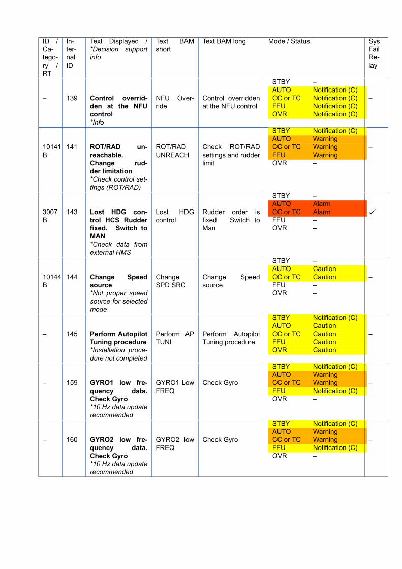
ID /Ca-tego-ry /RT
In-ter-nalID
Text Displayed /*Decision supportinfo
Text BAMshort
Text BAM long Mode / Status SysFailRe-lay
– 139 Control overrid-den at the NFUcontrol*Info
NFU Over-ride
Control overriddenat the NFU control
STBY –AUTO Notification (C)CC or TC Notification (C)FFU Notification (C)OVR Notification (C)
–
10141B
141 ROT/RAD un-reachable.Change rud-der limitation*Check control set-tings (ROT/RAD)
ROT/RADUNREACH
Check ROT/RADsettings and rudderlimit
STBY Notification (C)AUTO WarningCC or TC WarningFFU WarningOVR –
–
3007B
143 Lost HDG con-trol HCS Rudderfixed. Switch toMAN*Check data fromexternal HMS
Lost HDGcontrol
Rudder order isfixed. Switch toMan
STBY –AUTO AlarmCC or TC AlarmFFU –OVR –
10144B
144 Change Speedsource*Not proper speedsource for selectedmode
ChangeSPD SRC
Change Speedsource
STBY –AUTO CautionCC or TC CautionFFU –OVR –
–
– 145 Perform AutopilotTuning procedure*Installation proce-dure not completed
Perform APTUNI
Perform AutopilotTuning procedure
STBY Notification (C)AUTO CautionCC or TC CautionFFU CautionOVR Caution
–
– 159 GYRO1 low fre-quency data.Check Gyro*10 Hz data updaterecommended
GYRO1 LowFREQ
Check Gyro
STBY Notification (C)AUTO WarningCC or TC WarningFFU Notification (C)OVR –
–
– 160 GYRO2 low fre-quency data.Check Gyro*10 Hz data updaterecommended
GYRO2 lowFREQ
Check Gyro
STBY Notification (C)AUTO WarningCC or TC WarningFFU Notification (C)OVR –
–
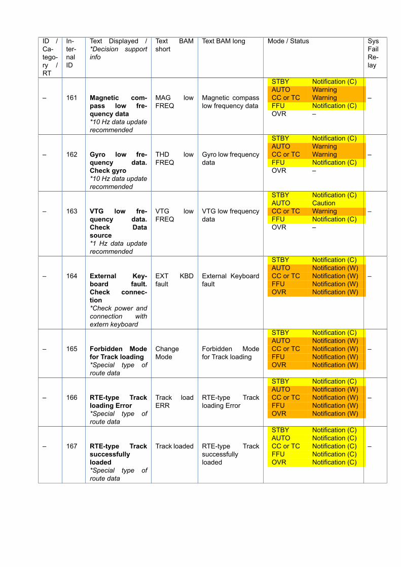
ID /Ca-tego-ry /RT
In-ter-nalID
Text Displayed /*Decision supportinfo
Text BAMshort
Text BAM long Mode / Status SysFailRe-lay
– 161 Magnetic com-pass low fre-quency data*10 Hz data updaterecommended
MAG lowFREQ
Magnetic compasslow frequency data
STBY Notification (C)AUTO WarningCC or TC WarningFFU Notification (C)OVR –
–
– 162 Gyro low fre-quency data.Check gyro*10 Hz data updaterecommended
THD lowFREQ
Gyro low frequencydata
STBY Notification (C)AUTO WarningCC or TC WarningFFU Notification (C)OVR –
–
– 163 VTG low fre-quency data.Check Datasource*1 Hz data updaterecommended
VTG lowFREQ
VTG low frequencydata
STBY Notification (C)AUTO CautionCC or TC WarningFFU Notification (C)OVR –
–
– 164 External Key-board fault.Check connec-tion*Check power andconnection withextern keyboard
EXT KBDfault
External Keyboardfault
STBY Notification (C)AUTO Notification (W)CC or TC Notification (W)FFU Notification (W)OVR Notification (W)
–
– 165 Forbidden Modefor Track loading*Special type ofroute data
ChangeMode
Forbidden Modefor Track loading
STBY Notification (C)AUTO Notification (W)CC or TC Notification (W)FFU Notification (W)OVR Notification (W)
–
– 166 RTE-type Trackloading Error*Special type ofroute data
Track loadERR
RTE-type Trackloading Error
STBY Notification (C)AUTO Notification (W)CC or TC Notification (W)FFU Notification (W)OVR Notification (W)
–
– 167 RTE-type Tracksuccessfullyloaded*Special type ofroute data
Track loaded RTE-type Tracksuccessfullyloaded
STBY Notification (C)AUTO Notification (C)CC or TC Notification (C)FFU Notification (C)OVR Notification (C)
–
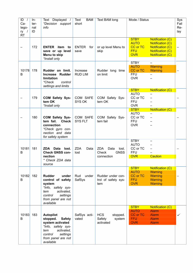
ID /Ca-tego-ry /RT
In-ter-nalID
Text Displayed /*Decision supportinfo
Text BAMshort
Text BAM long Mode / Status SysFailRe-lay
– 172 ENTER item tosave or up levelMenu to skip*Install only
ENTER forsave
or up level Menu toskip
STBY Notification (C)AUTO Notification (C)CC or TC Notification (C)FFU Notification (C)OVR Notification (C)
–
10178B
178 Rudder on limit.Increase Rudderlimitation*Check controlsettings and limits
IncreaseRUD LIM
Rudder long timeon limit
STBY –AUTO WarningCC or TC WarningFFU –OVR –
–
– 179 COM Safety Sys-tem OK*Install only
COM SAFESYS OK
COM Safety Sys-tem OK
STBY Notification (C)AUTO –CC or TC –FFU –OVR –
–
– 180 COM Safety Sys-tem fail. Checkconnection*Check gyro con-nection and datafor safety system
COM SAFESYS FLT
COM Safety Sys-tem fail
STBY Notification (C)AUTO –CC or TC –FFU –OVR –
–
10181B
181 ZDA Data lost.Check GNSS con-nection* Check ZDA datasource
ZDA Datalost
ZDA Data lost.Check GNSSconnection
STBY –AUTO –CC or TC –FFU –OVR Caution
–
10182B
182 Rudder undercontrol of safetysystem*Info, safety sys-tem activated,control settingsfrom panel are notavailable
Rud underSafSys
Rudder under con-trol of safety sys-tem
STBY Notification (C)AUTO WarningCC or TC WarningFFU WarningOVR Warning
–
10183B
183 Autopilotstopped. Safetysystem activated*Info, safety sys-tem activated,control settingsfrom panel are notavailable
SafSys acti-vated
HCS stopped.Safety systemactivated
STBY Notification (C)AUTO AlarmCC or TC AlarmFFU AlarmOVR Alarm
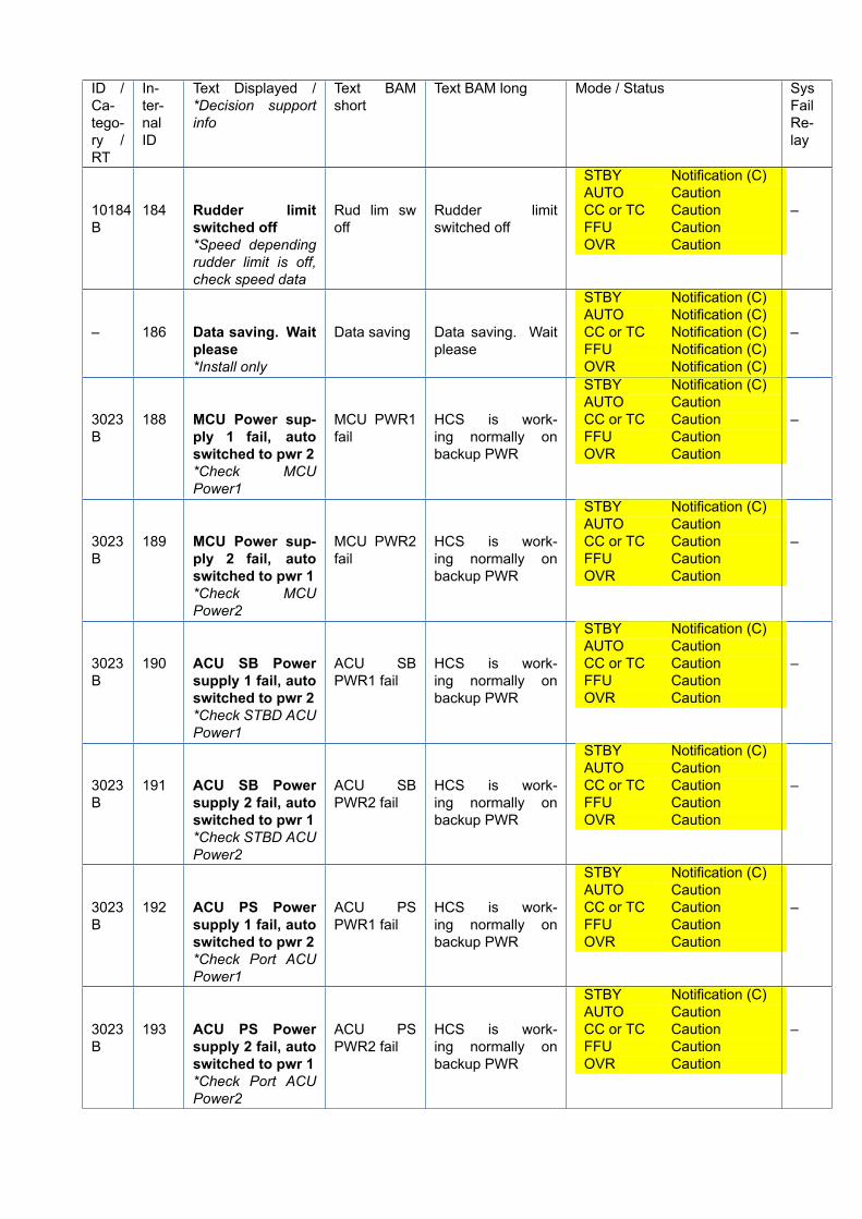
ID /Ca-tego-ry /RT
In-ter-nalID
Text Displayed /*Decision supportinfo
Text BAMshort
Text BAM long Mode / Status SysFailRe-lay
10184B
184 Rudder limitswitched off*Speed dependingrudder limit is off,check speed data
Rud lim swoff
Rudder limitswitched off
STBY Notification (C)AUTO CautionCC or TC CautionFFU CautionOVR Caution
–
– 186 Data saving. Waitplease*Install only
Data saving Data saving. Waitplease
STBY Notification (C)AUTO Notification (C)CC or TC Notification (C)FFU Notification (C)OVR Notification (C)
–
3023B
188 MCU Power sup-ply 1 fail, autoswitched to pwr 2*Check MCUPower1
MCU PWR1fail
HCS is work-ing normally onbackup PWR
STBY Notification (C)AUTO CautionCC or TC CautionFFU CautionOVR Caution
–
3023B
189 MCU Power sup-ply 2 fail, autoswitched to pwr 1*Check MCUPower2
MCU PWR2fail
HCS is work-ing normally onbackup PWR
STBY Notification (C)AUTO CautionCC or TC CautionFFU CautionOVR Caution
–
3023B
190 ACU SB Powersupply 1 fail, autoswitched to pwr 2*Check STBD ACUPower1
ACU SBPWR1 fail
HCS is work-ing normally onbackup PWR
STBY Notification (C)AUTO CautionCC or TC CautionFFU CautionOVR Caution
–
3023B
191 ACU SB Powersupply 2 fail, autoswitched to pwr 1*Check STBD ACUPower2
ACU SBPWR2 fail
HCS is work-ing normally onbackup PWR
STBY Notification (C)AUTO CautionCC or TC CautionFFU CautionOVR Caution
–
3023B
192 ACU PS Powersupply 1 fail, autoswitched to pwr 2*Check Port ACUPower1
ACU PSPWR1 fail
HCS is work-ing normally onbackup PWR
STBY Notification (C)AUTO CautionCC or TC CautionFFU CautionOVR Caution
–
3023B
193 ACU PS Powersupply 2 fail, autoswitched to pwr 1*Check Port ACUPower2
ACU PSPWR2 fail
HCS is work-ing normally onbackup PWR
STBY Notification (C)AUTO CautionCC or TC CautionFFU CautionOVR Caution
–
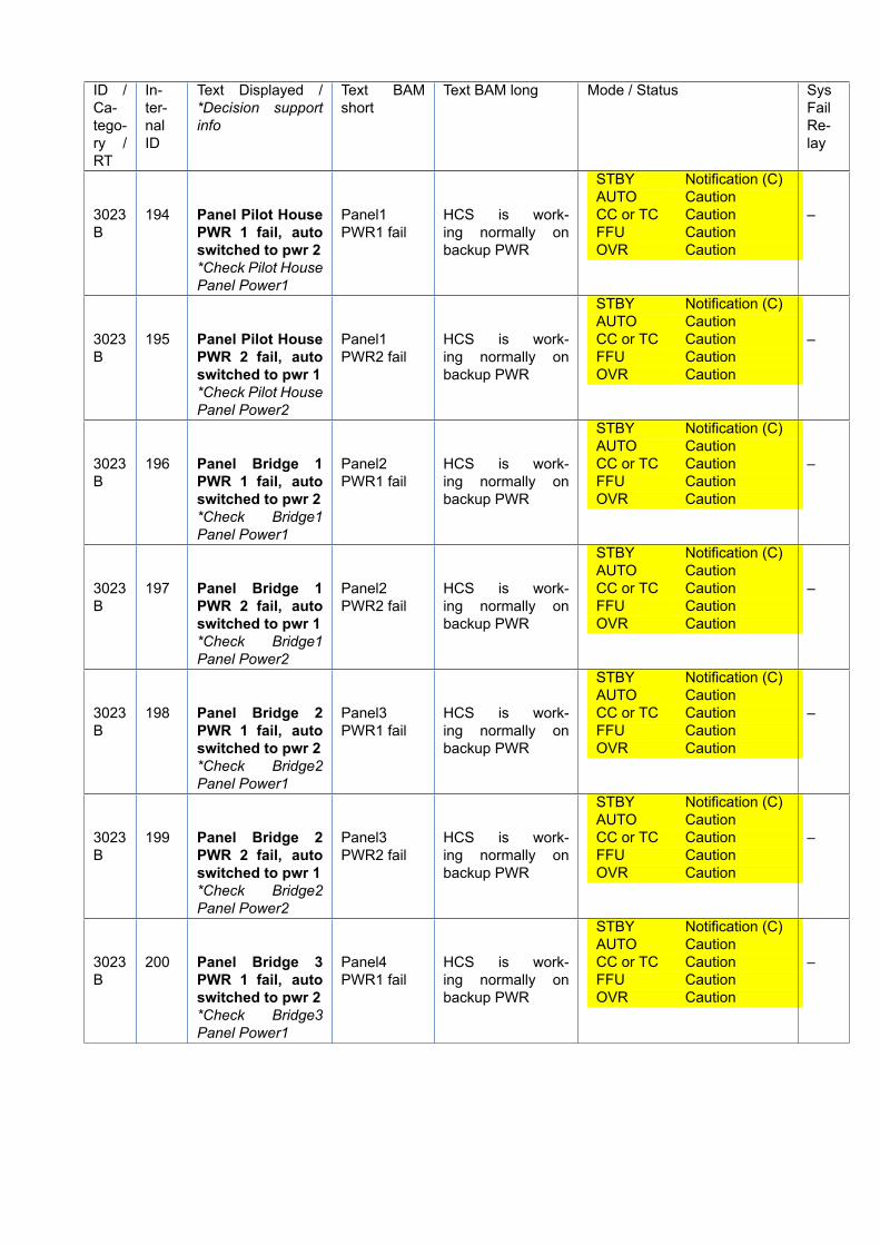
ID /Ca-tego-ry /RT
In-ter-nalID
Text Displayed /*Decision supportinfo
Text BAMshort
Text BAM long Mode / Status SysFailRe-lay
3023B
194 Panel Pilot HousePWR 1 fail, autoswitched to pwr 2*Check Pilot HousePanel Power1
Panel1PWR1 fail
HCS is work-ing normally onbackup PWR
STBY Notification (C)AUTO CautionCC or TC CautionFFU CautionOVR Caution
–
3023B
195 Panel Pilot HousePWR 2 fail, autoswitched to pwr 1*Check Pilot HousePanel Power2
Panel1PWR2 fail
HCS is work-ing normally onbackup PWR
STBY Notification (C)AUTO CautionCC or TC CautionFFU CautionOVR Caution
–
3023B
196 Panel Bridge 1PWR 1 fail, autoswitched to pwr 2*Check Bridge1Panel Power1
Panel2PWR1 fail
HCS is work-ing normally onbackup PWR
STBY Notification (C)AUTO CautionCC or TC CautionFFU CautionOVR Caution
–
3023B
197 Panel Bridge 1PWR 2 fail, autoswitched to pwr 1*Check Bridge1Panel Power2
Panel2PWR2 fail
HCS is work-ing normally onbackup PWR
STBY Notification (C)AUTO CautionCC or TC CautionFFU CautionOVR Caution
–
3023B
198 Panel Bridge 2PWR 1 fail, autoswitched to pwr 2*Check Bridge2Panel Power1
Panel3PWR1 fail
HCS is work-ing normally onbackup PWR
STBY Notification (C)AUTO CautionCC or TC CautionFFU CautionOVR Caution
–
3023B
199 Panel Bridge 2PWR 2 fail, autoswitched to pwr 1*Check Bridge2Panel Power2
Panel3PWR2 fail
HCS is work-ing normally onbackup PWR
STBY Notification (C)AUTO CautionCC or TC CautionFFU CautionOVR Caution
–
3023B
200 Panel Bridge 3PWR 1 fail, autoswitched to pwr 2*Check Bridge3Panel Power1
Panel4PWR1 fail
HCS is work-ing normally onbackup PWR
STBY Notification (C)AUTO CautionCC or TC CautionFFU CautionOVR Caution
–
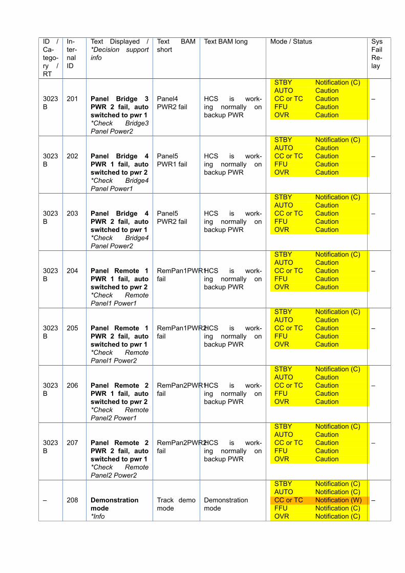
ID /Ca-tego-ry /RT
In-ter-nalID
Text Displayed /*Decision supportinfo
Text BAMshort
Text BAM long Mode / Status SysFailRe-lay
3023B
201 Panel Bridge 3PWR 2 fail, autoswitched to pwr 1*Check Bridge3Panel Power2
Panel4PWR2 fail
HCS is work-ing normally onbackup PWR
STBY Notification (C)AUTO CautionCC or TC CautionFFU CautionOVR Caution
–
3023B
202 Panel Bridge 4PWR 1 fail, autoswitched to pwr 2*Check Bridge4Panel Power1
Panel5PWR1 fail
HCS is work-ing normally onbackup PWR
STBY Notification (C)AUTO CautionCC or TC CautionFFU CautionOVR Caution
–
3023B
203 Panel Bridge 4PWR 2 fail, autoswitched to pwr 1*Check Bridge4Panel Power2
Panel5PWR2 fail
HCS is work-ing normally onbackup PWR
STBY Notification (C)AUTO CautionCC or TC CautionFFU CautionOVR Caution
–
3023B
204 Panel Remote 1PWR 1 fail, autoswitched to pwr 2*Check RemotePanel1 Power1
RemPan1PWR1fail
HCS is work-ing normally onbackup PWR
STBY Notification (C)AUTO CautionCC or TC CautionFFU CautionOVR Caution
–
3023B
205 Panel Remote 1PWR 2 fail, autoswitched to pwr 1*Check RemotePanel1 Power2
RemPan1PWR2fail
HCS is work-ing normally onbackup PWR
STBY Notification (C)AUTO CautionCC or TC CautionFFU CautionOVR Caution
–
3023B
206 Panel Remote 2PWR 1 fail, autoswitched to pwr 2*Check RemotePanel2 Power1
RemPan2PWR1fail
HCS is work-ing normally onbackup PWR
STBY Notification (C)AUTO CautionCC or TC CautionFFU CautionOVR Caution
–
3023B
207 Panel Remote 2PWR 2 fail, autoswitched to pwr 1*Check RemotePanel2 Power2
RemPan2PWR2fail
HCS is work-ing normally onbackup PWR
STBY Notification (C)AUTO CautionCC or TC CautionFFU CautionOVR Caution
–
– 208 Demonstrationmode*Info
Track demomode
Demonstrationmode
STBY Notification (C)AUTO Notification (C)CC or TC Notification (W)FFU Notification (C)OVR Notification (C)
–
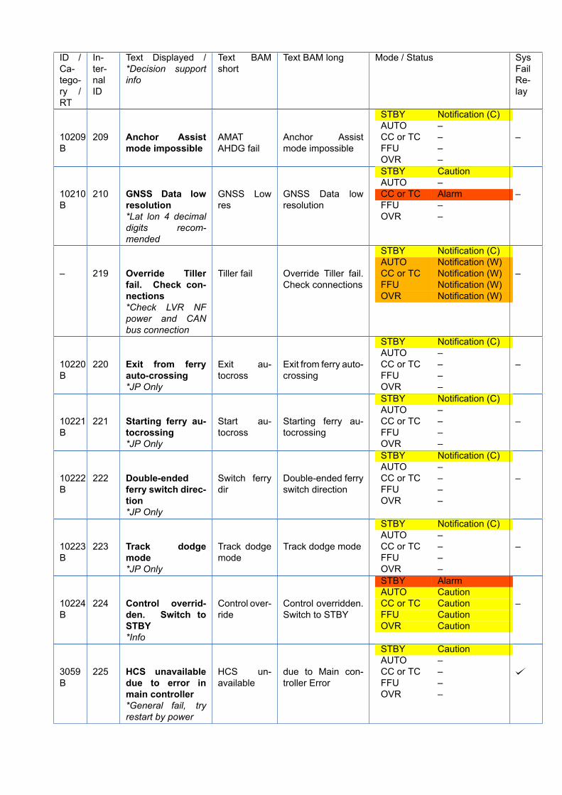
ID /Ca-tego-ry /RT
In-ter-nalID
Text Displayed /*Decision supportinfo
Text BAMshort
Text BAM long Mode / Status SysFailRe-lay
10209B
209 Anchor Assistmode impossible
AMATAHDG fail
Anchor Assistmode impossible
STBY Notification (C)AUTO –CC or TC –FFU –OVR –
–
10210B
210 GNSS Data lowresolution*Lat lon 4 decimaldigits recom-mended
GNSS Lowres
GNSS Data lowresolution
STBY CautionAUTO –CC or TC AlarmFFU –OVR –
–
– 219 Override Tillerfail. Check con-nections*Check LVR NFpower and CANbus connection
Tiller fail Override Tiller fail.Check connections
STBY Notification (C)AUTO Notification (W)CC or TC Notification (W)FFU Notification (W)OVR Notification (W)
–
10220B
220 Exit from ferryauto-crossing*JP Only
Exit au-tocross
Exit from ferry auto-crossing
STBY Notification (C)AUTO –CC or TC –FFU –OVR –
–
10221B
221 Starting ferry au-tocrossing*JP Only
Start au-tocross
Starting ferry au-tocrossing
STBY Notification (C)AUTO –CC or TC –FFU –OVR –
–
10222B
222 Double-endedferry switch direc-tion*JP Only
Switch ferrydir
Double-ended ferryswitch direction
STBY Notification (C)AUTO –CC or TC –FFU –OVR –
–
10223B
223 Track dodgemode*JP Only
Track dodgemode
Track dodge mode
STBY Notification (C)AUTO –CC or TC –FFU –OVR –
–
10224B
224 Control overrid-den. Switch toSTBY*Info
Control over-ride
Control overridden.Switch to STBY
STBY AlarmAUTO CautionCC or TC CautionFFU CautionOVR Caution
–
3059B
225 HCS unavailabledue to error inmain controller*General fail, tryrestart by power
HCS un-available
due to Main con-troller Error
STBY CautionAUTO –CC or TC –FFU –OVR –
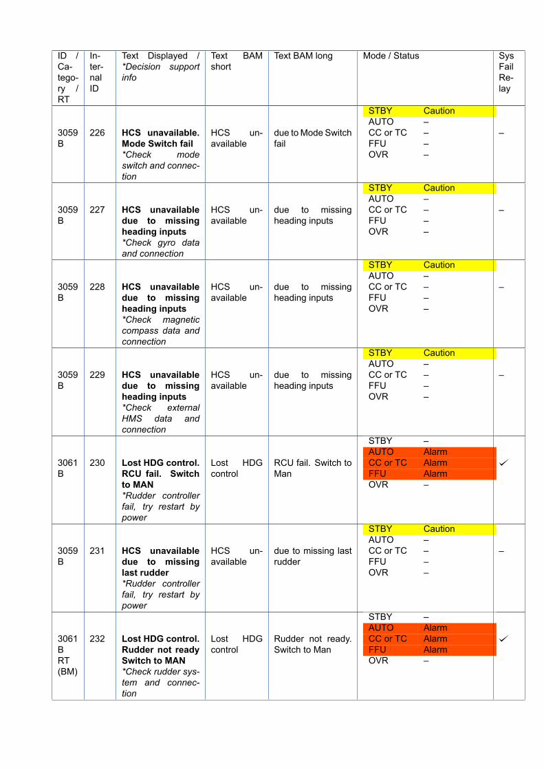
ID /Ca-tego-ry /RT
In-ter-nalID
Text Displayed /*Decision supportinfo
Text BAMshort
Text BAM long Mode / Status SysFailRe-lay
3059B
226 HCS unavailable.Mode Switch fail*Check modeswitch and connec-tion
HCS un-available
due toMode Switchfail
STBY CautionAUTO –CC or TC –FFU –OVR –
–
3059B
227 HCS unavailabledue to missingheading inputs*Check gyro dataand connection
HCS un-available
due to missingheading inputs
STBY CautionAUTO –CC or TC –FFU –OVR –
–
3059B
228 HCS unavailabledue to missingheading inputs*Check magneticcompass data andconnection
HCS un-available
due to missingheading inputs
STBY CautionAUTO –CC or TC –FFU –OVR –
–
3059B
229 HCS unavailabledue to missingheading inputs*Check externalHMS data andconnection
HCS un-available
due to missingheading inputs
STBY CautionAUTO –CC or TC –FFU –OVR –
–
3061B
230 Lost HDG control.RCU fail. Switchto MAN*Rudder controllerfail, try restart bypower
Lost HDGcontrol
RCU fail. Switch toMan
STBY –AUTO AlarmCC or TC AlarmFFU AlarmOVR –
3059B
231 HCS unavailabledue to missinglast rudder*Rudder controllerfail, try restart bypower
HCS un-available
due to missing lastrudder
STBY CautionAUTO –CC or TC –FFU –OVR –
–
3061BRT(BM)
232 Lost HDG control.Rudder not readySwitch to MAN*Check rudder sys-tem and connec-tion
Lost HDGcontrol
Rudder not ready.Switch to Man
STBY –AUTO AlarmCC or TC AlarmFFU AlarmOVR –
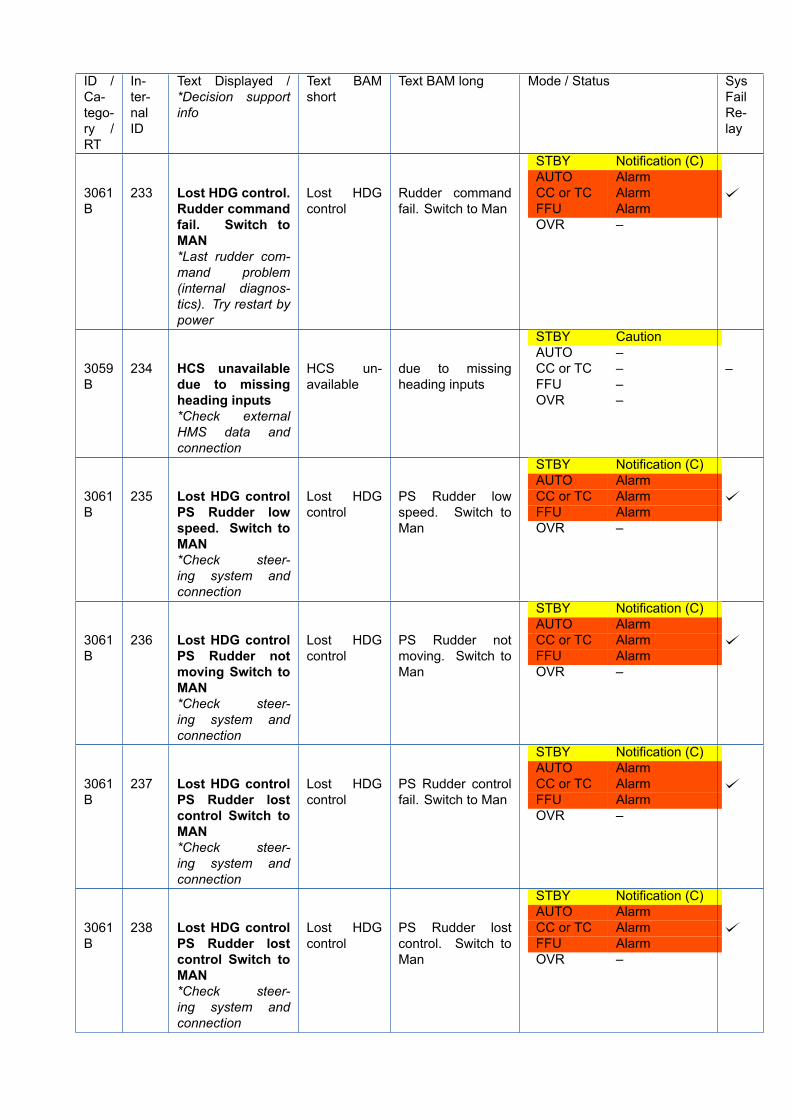
ID /Ca-tego-ry /RT
In-ter-nalID
Text Displayed /*Decision supportinfo
Text BAMshort
Text BAM long Mode / Status SysFailRe-lay
3061B
233 Lost HDG control.Rudder commandfail. Switch toMAN*Last rudder com-mand problem(internal diagnos-tics). Try restart bypower
Lost HDGcontrol
Rudder commandfail. Switch to Man
STBY Notification (C)AUTO AlarmCC or TC AlarmFFU AlarmOVR –
3059B
234 HCS unavailabledue to missingheading inputs*Check externalHMS data andconnection
HCS un-available
due to missingheading inputs
STBY CautionAUTO –CC or TC –FFU –OVR –
–
3061B
235 Lost HDG controlPS Rudder lowspeed. Switch toMAN*Check steer-ing system andconnection
Lost HDGcontrol
PS Rudder lowspeed. Switch toMan
STBY Notification (C)AUTO AlarmCC or TC AlarmFFU AlarmOVR –
3061B
236 Lost HDG controlPS Rudder notmoving Switch toMAN*Check steer-ing system andconnection
Lost HDGcontrol
PS Rudder notmoving. Switch toMan
STBY Notification (C)AUTO AlarmCC or TC AlarmFFU AlarmOVR –
3061B
237 Lost HDG controlPS Rudder lostcontrol Switch toMAN*Check steer-ing system andconnection
Lost HDGcontrol
PS Rudder controlfail. Switch to Man
STBY Notification (C)AUTO AlarmCC or TC AlarmFFU AlarmOVR –
3061B
238 Lost HDG controlPS Rudder lostcontrol Switch toMAN*Check steer-ing system andconnection
Lost HDGcontrol
PS Rudder lostcontrol. Switch toMan
STBY Notification (C)AUTO AlarmCC or TC AlarmFFU AlarmOVR –
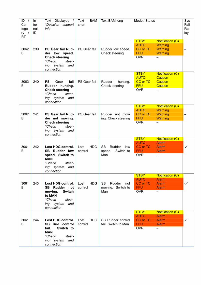
ID /Ca-tego-ry /RT
In-ter-nalID
Text Displayed /*Decision supportinfo
Text BAMshort
Text BAM long Mode / Status SysFailRe-lay
3062B
239 PS Gear fail Rud-der low speed.Check steering*Check steer-ing system andconnection
PS Gear fail Rudder low speed.Check steering
STBY Notification (C)AUTO WarningCC or TC WarningFFU WarningOVR –
–
3063B
240 PS Gear failRudder hunting.Check steering*Check steer-ing system andconnection
PS Gear fail Rudder hunting.Check steering
STBY Notification (C)AUTO CautionCC or TC CautionFFU CautionOVR –
–
3062B
241 PS Gear fail Rud-der not moving.Check steering*Check steer-ing system andconnection
PS Gear fail Rudder not mov-ing. Check steering
STBY Notification (C)AUTO WarningCC or TC WarningFFU WarningOVR –
–
3061B
242 Lost HDG control.SB Rudder lowspeed. Switch toMAN*Check steer-ing system andconnection
Lost HDGcontrol
SB Rudder lowspeed. Switch toMan
STBY Notification (C)AUTO AlarmCC or TC AlarmFFU AlarmOVR –
3061B
243 Lost HDG control.SB Rudder notmoving. Switchto MAN*Check steer-ing system andconnection
Lost HDGcontrol
SB Rudder notmoving. Switch toMan
STBY Notification (C)AUTO AlarmCC or TC AlarmFFU AlarmOVR –
3061B
244 Lost HDG control.SB Rud controlfail. Switch toMAN*Check steer-ing system andconnection
Lost HDGcontrol
SB Rudder controlfail. Switch to Man
STBY Notification (C)AUTO AlarmCC or TC AlarmFFU AlarmOVR –
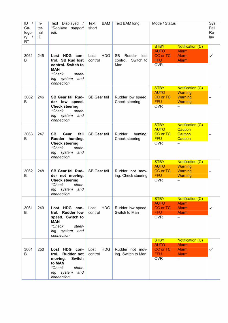
ID /Ca-tego-ry /RT
In-ter-nalID
Text Displayed /*Decision supportinfo
Text BAMshort
Text BAM long Mode / Status SysFailRe-lay
3061B
245 Lost HDG con-trol. SB Rud lostcontrol. Switch toMAN*Check steer-ing system andconnection
Lost HDGcontrol
SB Rudder lostcontrol. Switch toMan
STBY Notification (C)AUTO AlarmCC or TC AlarmFFU AlarmOVR –
3062B
246 SB Gear fail Rud-der low speed.Check steering*Check steer-ing system andconnection
SB Gear fail Rudder low speed.Check steering
STBY Notification (C)AUTO WarningCC or TC WarningFFU WarningOVR –
–
3063B
247 SB Gear failRudder hunting.Check steering*Check steer-ing system andconnection
SB Gear fail Rudder hunting.Check steering
STBY Notification (C)AUTO CautionCC or TC CautionFFU CautionOVR –
–
3062B
248 SB Gear fail Rud-der not moving.Check steering*Check steer-ing system andconnection
SB Gear fail Rudder not mov-ing. Check steering
STBY Notification (C)AUTO WarningCC or TC WarningFFU WarningOVR –
–
3061B
249 Lost HDG con-trol. Rudder lowspeed. Switch toMAN*Check steer-ing system andconnection
Lost HDGcontrol
Rudder low speed.Switch to Man
STBY Notification (C)AUTO AlarmCC or TC AlarmFFU AlarmOVR –
3061B
250 Lost HDG con-trol. Rudder notmoving. Switchto MAN*Check steer-ing system andconnection
Lost HDGcontrol
Rudder not mov-ing. Switch to Man
STBY Notification (C)AUTO AlarmCC or TC AlarmFFU AlarmOVR –
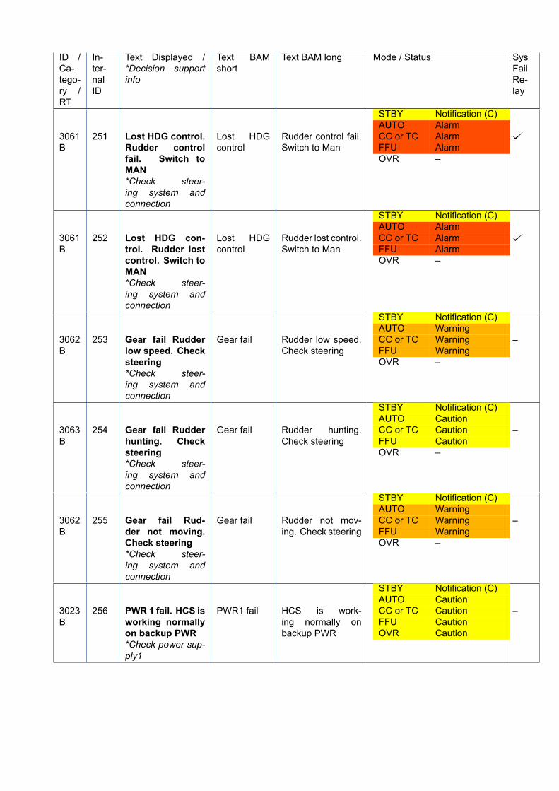
ID /Ca-tego-ry /RT
In-ter-nalID
Text Displayed /*Decision supportinfo
Text BAMshort
Text BAM long Mode / Status SysFailRe-lay
3061B
251 Lost HDG control.Rudder controlfail. Switch toMAN*Check steer-ing system andconnection
Lost HDGcontrol
Rudder control fail.Switch to Man
STBY Notification (C)AUTO AlarmCC or TC AlarmFFU AlarmOVR –
3061B
252 Lost HDG con-trol. Rudder lostcontrol. Switch toMAN*Check steer-ing system andconnection
Lost HDGcontrol
Rudder lost control.Switch to Man
STBY Notification (C)AUTO AlarmCC or TC AlarmFFU AlarmOVR –
3062B
253 Gear fail Rudderlow speed. Checksteering*Check steer-ing system andconnection
Gear fail Rudder low speed.Check steering
STBY Notification (C)AUTO WarningCC or TC WarningFFU WarningOVR –
–
3063B
254 Gear fail Rudderhunting. Checksteering*Check steer-ing system andconnection
Gear fail Rudder hunting.Check steering
STBY Notification (C)AUTO CautionCC or TC CautionFFU CautionOVR –
–
3062B
255 Gear fail Rud-der not moving.Check steering*Check steer-ing system andconnection
Gear fail Rudder not mov-ing. Check steering
STBY Notification (C)AUTO WarningCC or TC WarningFFU WarningOVR –
–
3023B
256 PWR 1 fail. HCS isworking normallyon backup PWR*Check power sup-ply1
PWR1 fail HCS is work-ing normally onbackup PWR
STBY Notification (C)AUTO CautionCC or TC CautionFFU CautionOVR Caution
–
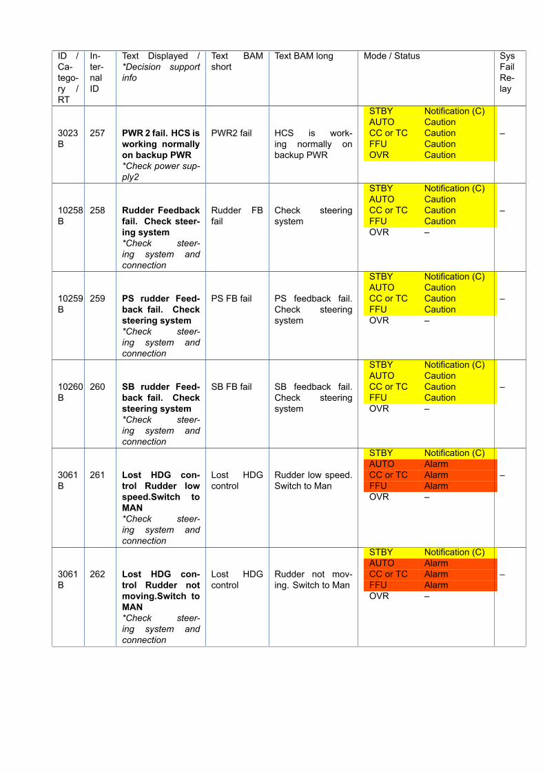
ID /Ca-tego-ry /RT
In-ter-nalID
Text Displayed /*Decision supportinfo
Text BAMshort
Text BAM long Mode / Status SysFailRe-lay
3023B
257 PWR 2 fail. HCS isworking normallyon backup PWR*Check power sup-ply2
PWR2 fail HCS is work-ing normally onbackup PWR
STBY Notification (C)AUTO CautionCC or TC CautionFFU CautionOVR Caution
–
10258B
258 Rudder Feedbackfail. Check steer-ing system*Check steer-ing system andconnection
Rudder FBfail
Check steeringsystem
STBY Notification (C)AUTO CautionCC or TC CautionFFU CautionOVR –
–
10259B
259 PS rudder Feed-back fail. Checksteering system*Check steer-ing system andconnection
PS FB fail PS feedback fail.Check steeringsystem
STBY Notification (C)AUTO CautionCC or TC CautionFFU CautionOVR –
–
10260B
260 SB rudder Feed-back fail. Checksteering system*Check steer-ing system andconnection
SB FB fail SB feedback fail.Check steeringsystem
STBY Notification (C)AUTO CautionCC or TC CautionFFU CautionOVR –
–
3061B
261 Lost HDG con-trol Rudder lowspeed.Switch toMAN*Check steer-ing system andconnection
Lost HDGcontrol
Rudder low speed.Switch to Man
STBY Notification (C)AUTO AlarmCC or TC AlarmFFU AlarmOVR –
–
3061B
262 Lost HDG con-trol Rudder notmoving.Switch toMAN*Check steer-ing system andconnection
Lost HDGcontrol
Rudder not mov-ing. Switch to Man
STBY Notification (C)AUTO AlarmCC or TC AlarmFFU AlarmOVR –
–
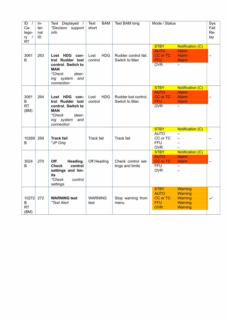
ID /Ca-tego-ry /RT
In-ter-nalID
Text Displayed /*Decision supportinfo
Text BAMshort
Text BAM long Mode / Status SysFailRe-lay
3061B
263 Lost HDG con-trol Rudder lostcontrol. Switch toMAN*Check steer-ing system andconnection
Lost HDGcontrol
Rudder control fail.Switch to Man
STBY Notification (C)AUTO AlarmCC or TC AlarmFFU AlarmOVR –
–
3061BRT(BM)
264 Lost HDG con-trol Rudder lostcontrol. Switch toMAN*Check steer-ing system andconnection
Lost HDGcontrol
Rudder lost control.Switch to Man
STBY Notification (C)AUTO AlarmCC or TC AlarmFFU AlarmOVR –
–
10269B
269 Track fail*JP Only
Track fail Track fail
STBY Notification (C)AUTO –CC or TC –FFU –OVR –
–
3024B
270 Off Heading.Check controlsettings and lim-its*Check controlsettings
Off Heading Check control set-tings and limits
STBY Notification (C)AUTO AlarmCC or TC AlarmFFU –OVR –
–
10272BRT(BM)
272 WARNING test*Test Alert
WARNINGtest
Stop warning frommenu
STBY WarningAUTO WarningCC or TC WarningFFU WarningOVR Warning
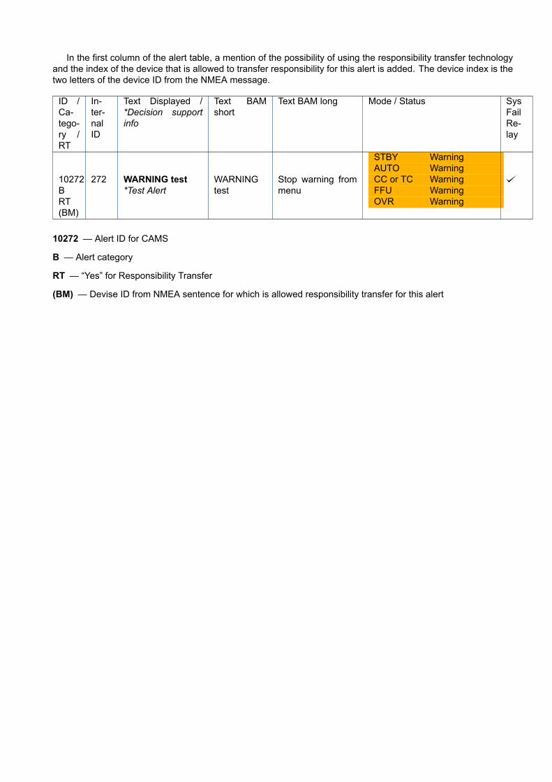
In the first column of the alert table, a mention of the possibility of using the responsibility transfer technologyand the index of the device that is allowed to transfer responsibility for this alert is added. The device index is thetwo letters of the device ID from the NMEA message.
ID /Ca-tego-ry /RT
In-ter-nalID
Text Displayed /*Decision supportinfo
Text BAMshort
Text BAM long Mode / Status SysFailRe-lay
10272BRT(BM)
272 WARNING test*Test Alert
WARNINGtest
Stop warning frommenu
STBY WarningAUTO WarningCC or TC WarningFFU WarningOVR Warning
10272 — Alert ID for CAMS
B — Alert category
RT — “Yes” for Responsibility Transfer
(BM) — Devise ID from NMEA sentence for which is allowed responsibility transfer for this alert
All over the world,
close to the customer
JRC/Alphatron Marine Schaardijk 23 (harbor 115) 3063 NH Rotterdam The Netherlands T +31 10 453 4000 F +31 10 453 4010 [email protected] ww.alphatronmarine.com
The information in this document is subject to change without noticeand does not represent a commitment on the part of Alphatron Marine B.V.
Document name Document type Document nr. Version
: AlphaPilot MFM : Operation Manual : 1030_OM : V2.2
© All rights reserved Alphatron Marine B.V.
Centers of Excellence
Houston, Rotterdam, Singapore, Tokyo