Embed Size (px)
Citation preview

AGENDA
NFPA TECHNICAL COMMITTEE ON INIATING DEVICES FOR FIRE ALARM AND SIGNALING SYSTEMS
Report on Proposal Meeting
January 17-19, 2011 Hard Rock Hotel
San Diego, CA
Item No. Subject 11-1-1 Call to Order 11-1-2 Introduction of Members and Guests 11-1-3 Staff Remarks 11-1-4 Chair Remarks 11-1-5 Task Group Reports 11-1-6 Processing of Proposals [Enclosure] 11-1-7 Other Business 11-1-8 Adjournment

Proposal # Log#Comm.Action
Tech.Comm. Section
Sort Listing
CP4 Entire Document- ( ):72-4 SIG-IDS
20a 2.3.1- ( ):72- SIG-IDS
498b 3.3.52 Condition, 3.3.228 Response, and 3.3.240- ( ):72-24 SIG-IDS
72 3.3.59 Detector and 3.3.59.xx Gas Detector- ( ):72-31 SIG-IDS
117b Chapter 4- ( ):72-61 SIG-IDS
333b Chapter 8- ( ):72-70 SIG-IDS
584 17.1.1- ( ):72-231a SIG-IDS
425 17.1.2 and A.17.1.2 (New)- ( ):72-232 SIG-IDS
4 17.4.9 and 17.7.5.5.8- ( ):72-233 SIG-IDS
238 17.5.3.1.4- ( ):72-234 SIG-IDS
585 17.5.3.2- ( ):72-234a SIG-IDS
612 Table 17.6.3.5.1- ( ):72-234b SIG-IDS
613 Table 17.6.3.5.1- ( ):72-234c SIG-IDS
16 17.6.3.5.2- ( ):72-235 SIG-IDS
17 17.7.3.1.3- ( ):72-236 SIG-IDS
536 17.7.3.2.3, 17.7.3.2.3.1, and 17.7.3.2.3.5- ( ):72-237 SIG-IDS
132 17.7.3.3.1- ( ):72-238 SIG-IDS
121 17.7.3.6.1- ( ):72-239 SIG-IDS
586 17.7.3.6.2- ( ):72-239a SIG-IDS
197 17.7.4.2.2 (New)- ( ):72-240 SIG-IDS
199 17.7.5.2.3 (New)- ( ):72-241 SIG-IDS
239 17.7.5.4.2.2- ( ):72-242 SIG-IDS
200 17.7.5.5.5 (New)- ( ):72-243 SIG-IDS
10 17.7.5.6- ( ):72-244 SIG-IDS
110 Table 17.7.6.3.3.1- ( ):72-245 SIG-IDS
249 17.7.7.5 (New)- ( ):72-246 SIG-IDS
125 17.10.2.1- ( ):72-247 SIG-IDS
126 17.10.2.2- ( ):72-248 SIG-IDS
202 17.12.2- ( ):72-249 SIG-IDS
435 17.14.3, 17.4.4, and A.17.4.4 (New)- ( ):72-250 SIG-IDS
204 17.14.5 (New)- ( ):72-251 SIG-IDS
332 17.16.1.3- ( ):72-252 SIG-IDS
331 17.16.1.5- ( ):72-253 SIG-IDS
322 17.16.2.2.2- ( ):72-254 SIG-IDS
321 17.16.5.1 (New)- ( ):72-255 SIG-IDS
240 A.17.5.3.1.4 (New)- ( ):72-578 SIG-IDS
608 A.17.6.3.5.2- ( ):72-578a SIG-IDS
475 A.17.7.3.1.4- ( ):72-579 SIG-IDS
477 A.17.7.3.1.4- ( ):72- SIG-IDS
120 A.17.7.3.6.6- ( ):72-580 SIG-IDS
Page 1A2012Cycle

Proposal # Log#Comm.Action
Tech.Comm. Section
Sort Listing
604 A.17.7.3.6.6- ( ):72-580a SIG-IDS
198 A.17.7.4.2.2 (New)- ( ):72-581 SIG-IDS
241 A.17.7.5.4.2.2- ( ):72-582 SIG-IDS
201 A.17.7.5.5.5 (New)- ( ):72-583 SIG-IDS
203 A.17.12.2- ( ):72-584 SIG-IDS
205 A.17.14.5 (New)- ( ):72-585 SIG-IDS
21 B.6.5- ( ):72-603 SIG-IDS
24 H.1.2.1- ( ):72-611 SIG-IDS
Page 2A2012Cycle

Report on Proposals – June 2012 NFPA 72_______________________________________________________________________________________________72- Log #20a SIG-IDS
_______________________________________________________________________________________________John F. Bender, Underwriters Laboratories Inc.
Update the references to the following ANSI Publications:ANSI/UL 217, , 2006, revised 2008 2010. (SIG-HOU)ANSI/UL 268, , 2006 2009. (SIG-IDS)ANSI/UL 864, , 2003, revised 2006 2010.
(SIG-ECS)ANSI/UL 985, , 2000, revised 2003 2008. (SIG-HOU)ANSI/UL 2017, , 2000 2008, revised 2004 2009.
(SIG-ECS)Update referenced standards to the most recent revisions and add ANSI approval designation to
ANSI/UL 2017. The revisions to UL 217 include clarification of Smoldering Smoke Test wood stick amount andorientation new surge tests, a reference to NFPA 302 in Scope and addition of lower beam limits for flammable liquidfuel fire. UL 268 is the first publication of the common UL and ULC standard for Smoke Detectors for Fire AlarmSystems. National differences are identified in the new standard. UL 864 has been revised to include Fail-Safe FireRelease Devices. UL 985 reflects the recent reaffirmation as an American National Standard. The revisions of ANSI/UL2017 are to address universal upkeep of UL Standards for Safety. These revisions are considered to benon-substantive.
_______________________________________________________________________________________________72- Log #477 SIG-IDS
_______________________________________________________________________________________________Daniel G. Decker, Safety Systems, Inc.
_______________________________________________________________________________________________72-4 Log #CP4 SIG-IDS
_______________________________________________________________________________________________Technical Committee on Initiating Devices for Fire Alarm Systems,
Review entire document to: 1) Update any extracted material by preparing separate proposals todo so, and 2) review and update references to other organizations documents, by preparing proposal(s) as required.
To conform to the NFPA Regulations Governing Committee Projects.
1Printed on 12/13/2010

Report on Proposals – June 2012 NFPA 72_______________________________________________________________________________________________72-24 Log #498b SIG-IDS
_______________________________________________________________________________________________Andrew G. Berezowski, Honeywell Inc.
Add new text to read as follows:
The state of an environment, fire alarm, or signaling or system
A situation, environmental state, or equipment state that warrants some type of signal, notification, communication,response, action or service.
An environment that poses an immediate threat to life, property, or mission.
A potential threat to life or property may be present and time is available for investigation.
The complete failure of a protection system (e.g. fire system inoperable, ECS inoperable, sprinkler system inoperable,etc.), or an event causing the activation of a supervisory initiating device used to monitor an environmental element,system element, component, or function, whose failure poses a high risk to life, property or mission (e.g. sprinkler valveclosed, water tank low water level, low building temperature, etc.), or the absence of a guard’s tour supervisory signalwithin prescribed timing requirements, or the presence of a guards’ tour supervisory signal outside of prescribedsequencing requirements, or the presence of a delinquency signal.
High risk elements, components, and functions should be identified using risk analysis.
A fault in a portion of a system monitored for integrity that does not render the complete system inoperable.
The environment is within acceptable limits, circuits, systems, and components are functioning as designed and noabnormal condition exists.
Actions taken on the receipt of a signal and the results of those actions
Actions taken on receipt of an alarm signal or of multiple alarm signals and the results of those actions such as: theactuation of alarm notification appliances, elevator recall, smoke control measures, emergency responder dispatch,deployment of resources in accordance with a risk analysis and emergency action plan, etc.
Actions taken on receipt of a pre-alarm signal or of multiple pre-alarm signals and the results of those actions such as:the actuation of notification appliances, dispatch of personnel, investigation of circumstances and problem resolution inaccordance with a risk analysis and action plan, etc.
Actions taken on receipt of a delinquency signal or of a supervisory signal that indicates the presence of a supervisorycondition or of multiple supervisory signals that indicate multiple supervisory conditions, and the results of those actionssuch as: the actuation of supervisory notification appliances, the shutdown of appliances, fan shutdown or activation,dispatch of personnel, investigation of circumstances and problem resolution in accordance with a risk analysis andaction plan, etc.
Actions taken on receipt of a trouble signal or multiple trouble signals and the results of those actions such as: theactivation of trouble notification appliances, dispatch of service personnel, deployment of resources in accordance withan action plan etc.
A message status indication indicating a condition, communicated by electrical, visible, audible, wireless, or othermeans. (SIG-FUN)
A signal indicating an emergency condition or an alert that requires action. A message (in any form) that results fromthe manual or automatic detection of an alarm condition including: outputs of activated alarm initiating devices, the lightand sound from actuated alarm notification appliances, etc. (SIG-FUN)
2Printed on 12/13/2010

Report on Proposals – June 2012 NFPA 72A signal indicating the need for action in connection with the supervision of guards or system attendants. (SIG-PRO)
A distinctive alarm signal intended to be recognized by the occupants as requiring evacuation of the building. (SIG-PRO)
A signal initiated by An alarm signal that results from the manual or automatic detection of a fire alarm conditionincluding: outputs from a activated fire alarm-initiating devices such as a manual fire alarm box, automatic fire detector,waterflow switch, or other device in which activation is indicative of the presence of a fire or fire signature. (SIG-FUN)
A supervisory signal monitoring the performance of guard patrols indicating that a guard has activated a guard’s tourreporting station. (SIG-PRO)
A message (in any form) that results from the detection of a pre-alarm condition including: outputs of analog initiatingdevices prior to reaching alarm levels, information regarding the activities of terrorists, the light and sound from actuatednotification appliances, etc.
A message (in any form) that results from the return to normal (deactivation) of an activated initiating device or systemindicating the absence of an abnormal condition at the location of the initiating device or system.
A signal indicating the need for action in connection with the supervision of guard tours, the fire suppression systems orequipment, or the maintenance features of related systems. In systems other than those supporting guard’s toursupervisory service, a message (in any form) that results from the manual or automatic detection of a supervisorycondition including: activated supervisory signal-initiating device outputs, transmissions to supervising stations, the lightand sound from actuated supervisory notification appliances, etc. In systems supporting guard’s tour supervisoryservice, a message indicating that a guard has activated a guard’s tour reporting station (not in itself an indication of asupervisory condition) or a delinquency signal indicating a supervisory condition. (SIG-FUN)
A signal initiated by a system or device indicative of a fault in a monitored circuit, system, or component. A message (inany form) that results from the manual or automatic detection of a trouble condition including: off-normal outputs fromintegrity monitoring circuits, the light and sound from actuated trouble notification appliances, etc. (SIG-FUN)
This proposal is the result of the work of the SIG-ACC Alarm Trouble and Supervisory Task Group(ATS TG) charged with developing definitions for the use of the terms alarm, trouble and supervisory in the context oftheir three forms of use (as a condition or state, as a signal indicating the presence of a state, and as a response oraction in association with receiving a signal). Those participating in the task group were: Larry Shudak, Wayne Moore,Frank Van Overmeiren, Ray Grill, and Andrew Berezowski. These proposed definitions and revised definitions areprovided for use by other TCs in the ROP meetings so that they might develop proposals to clarify the use of termswithin their chapters and improve the flow/understanding of the code. New definitions and sub-definitions have beendeveloped for the terms Condition and Response. The term Pre-Alarm has been introduced for possible use in place of“supervisory smoke detection” and “supervisory carbon monoxide” so that the original meaning of the term Supervisorymight be clarified and preserved. The proposed definitions and revised definitions have been presented as a group sothat they may be evaluated collectively.
3Printed on 12/13/2010

Report on Proposals – June 2012 NFPA 72_______________________________________________________________________________________________72-31 Log #72 SIG-IDS
_______________________________________________________________________________________________Samuel M. Miller, BP Exploration Alaska
Revise text to read as follows:3.3.59 Detector. A device suitable for connection to a circuit that has a sensor that responds to a physical stimulus
such as gas, heat or smoke.3.3.59.xx Gas Detector. A device that detects the presence of a specified gas concentration. Gas detectors can be
either spot-type or line-type detectors.Gas detection devices which detect combustible, flammable or toxic gases are routinely installed to
initiate occupant evacuation, or other control functions to mitigate the risk of an explosion or fire. Many times thesefunctions are combined with a building or facility fire alarm system. Section 17.10 was added to the 2010 edition ofNFPA 72 and it outlines minimum requirements when these detectors are added on a fire alarm system. Section 3.3.59defines the types of detectors covered by chapter 17 and it does not include a definition for a gas detector which is notrelated to detecting gases produced from a fire. The addition of the proposed text clarifies gas detection devices arerecognized by the standard and it maintains consistency with chapter 17.
4Printed on 12/13/2010

Report on Proposals – June 2012 NFPA 72_______________________________________________________________________________________________72-61 Log #117b SIG-IDS
_______________________________________________________________________________________________Merton W. Bunker, Jr., US Department of State
(1) Add new Chapter 4 as follows:
****Insert Include 72_L117_R Here****
2. Insert existing Figure 10.18.2.1.1 as new Figure 4.3.2.2.3.2.
3. Insert existing Figure A.10.2.1.1 as Figure A.4.3.2.2.3.2
4. Delete existing Section 10.18 in its entirety, to include Sections A.10.18.1.4, A.10.18.2.1.1, A.10.18.2.3(1), andA.10.18.2.4.
5. Renumber existing Section 10.19 as Section 10.18.
6. Delete existing Sections 14.6.1.2 and A.14.6.1.2.
1. The items required by the proposed sections are necessary to assist technicians in the properinstallation, programming, and maintenance of the system. Good shop drawings will facilitate a better installation,resulting in a more reliable and more easily maintained system.
2. These items can, and sometimes do, appear in fire alarm specifications. However, many systems are installedwithout the benefit of specifications. In this case, there is no requirement to provide adequate drawings.
3. NFPA 13 contains a similar list of requirements for working drawings in the body of the standard. NFPA 72 shouldalso contain these requirements.
4. National and local building codes require some of the items added by this proposal. This proposal seeks to placethese requirements in NFPA 72, rather than in a building code.
5Printed on 12/13/2010

1 NFPA 72 Log #117 Rec A2012 ROP
Chapter 4 – Approvals and Documentation 4.1 Application. All system approvals and documentation shall comply with the minimum requirements of this chapter. 4.2 Approvals. 4.2.1 Notification. The authority having jurisdiction shall be notified prior to installation or alteration of equipment or wiring. 4.2.2 Required Documentation. At the authority having jurisdiction’s request, complete information as required by Section 4.3 shall be submitted for approval. 4.3 Documentation. 4.3.1 Working Plans (Shop drawings). Working plans (shop drawings) shall be drawn to an indicated scale, on sheets of uniform size, with a plan of each floor. 4.3.1.1 General. Shop drawings for fire alarm systems shall provide basic information and shall provide the basis for the record (as-built) drawings required elsewhere in this Code. 4.3.1.2 Content. Working plans (shop drawings) shall include the following information: (1) Name of protected premises, owner, and occupant (where applicable) (2) Name of installer or contractor (3) Location of protected premises (4) Device legend in accordance with NFPA 170, Standard for Fire Safety and Emergency Symbols (5) Date of issue and any revisions 4.3.1.3 Floor Plans. Floor plan drawings shall be drawn to an indicated scale and shall include the following information: (1) Floor identification (2) Point of compass (indication of north) (3) Graphic scale (4) All walls and doors (5) All partitions extending to within 10 percent of the ceiling height (where applicable) (6) Room descriptions (7) Fire alarm device/component locations (8) Locations of fire alarm primary power connection(s) (9) Locations of monitor/control interfaces to other systems (10) Riser locations (11) Type and number of fire alarm system components/devices on each circuit, on each floor or level (12) Type and quantity of conductors and conduit (if used) used for each circuit (13) Location of all supply and return air diffusers (where automatic detection is used)

2 NFPA 72 Log #117 Rec A2012 ROP
(14) Identification of any ceiling over 10 feet in height where automatic fire detection is being proposed. (15) Details of ceiling geometries, including beams and solid joists, where automatic fire detection is being proposed. 4.3.1.4 Riser Diagrams. Fire alarm system riser diagrams shall include the following information: (1) General arrangement of the system in building cross-section (2) Number of risers (3) Type and number of circuits in each riser (4) Type and number of fire alarm system components/devices on each circuit, on each floor or level (5) Type and quantity of conductors and conduit (if used) for each circuit. 4.3.1.5 Control Unit Diagrams. Control unit wiring diagrams shall be provided for all control equipment (i.e., equipment listed as either a control unit or control unit accessory), power supplies, battery chargers, and annunciators and shall include the following information: (1) Identification of the control equipment depicted (2) Location(s) (3) All field wiring terminals and terminal identifications (4) All circuits connected to field wiring terminals and circuit identifications (5) All indicators and manual controls, including the full text of all labels (6) All field connections to supervising station signaling equipment, releasing equipment, and fire safety control interfaces 4.3.1.6 Typical Wiring Diagrams. Typical wiring diagrams shall be provided for all initiating devices, notification appliances, remote indicators, annunciators, remote test stations, and end-of-line and power supervisory devices. 4.3.1.7* Matrix of Operation. A matrix of operation shall be provided on all working drawings. 4.3.1.8 Calculations. System calculations shall be provided with all shop drawings as follows: (1) Battery calculations (2) Loop resistance calculations (if required) (3) Notification appliance circuit voltage drop calculations 4.3.2 Completion Documents. 4.3.2.1 General. Before requesting final approval of the installation, the installing contractor shall furnish a written statement stating that the system has been installed in accordance with approved plans and tested in accordance with the manufacturer’s published instructions and the appropriate NFPA requirements. 4.3.2.2 Documentation Required. Every system shall include the following documentation, which shall be delivered to the owner or the owner’s representative upon final acceptance of the system:

3 NFPA 72 Log #117 Rec A2012 ROP
(1)An owner’s manual and manufacturer’s published instructions covering all system equipment, as described in Section 4.3.2.2.1 (2) Record (as-built) drawings, as described in Section 4.3.2.2.2 (3) A record of completion (4) For software-based systems, record copy of the site-specific software (5) A contractor’s statement as described in Section 4.3.2.1. 4.3.2.2.1 Owner’s Manual. An owner’s manual shall contain the following documentation: (1) A detailed narrative description of the system inputs, evacuation signaling, ancillary functions, annunciation, intended sequence of operations, expansion capability, application considerations, and limitations (2) A written sequence of operation for the system. (3) Operator instructions for basic system operations, including alarm acknowledgment, system reset, interpretation of system output (LEDs, CRT display, and printout), operation of manual evacuation signaling and ancillary function controls, and change of printer paper (4) A detailed description of routine maintenance and testing as required and recommended and as would be provided under a maintenance contract, including testing and maintenance instructions for each type of device installed. This information shall include the following: (a) Listing of the individual system components that require periodic testing and maintenance (b) Step-by-step instructions detailing the requisite testing and maintenance procedures, and the intervals at which these procedures shall be performed, for each type of device installed (c) A schedule that correlates the testing and maintenance procedures that are required by this section (5) Detailed troubleshooting instructions for each trouble condition generated from the monitored field wiring, including opens, grounds, and loop failures. These instructions shall include a list of all trouble signals annunciated by the system, a description of the condition(s) that causes such trouble signals, and step-by-step instructions describing how to isolate such problems and correct them (or how to call for service, as appropriate).] (6) A service directory, including a list of names and telephone numbers of those who provide service for the system. 4.3.2.2.2 Record (As-Built) Drawings. Record drawings shall be drawn to an indicated scale, on sheets of uniform size, with a plan of each floor. 4.3.2.2.21.1 General. Record drawings for fire alarm systems shall provide basic information and shall reflect the actual installation of all equipment, components, and wiring. 4.3.2.2.2.1.2 Content. Record drawings shall include the following information: (1) Name of protected premises, owner, and occupant (where applicable) (2) Name of installer or contractor (3) Location of protected premises (4) Device legend in accordance with NFPA 170, Standard for Fire Safety and Emergency Symbols

4 NFPA 72 Log #117 Rec A2012 ROP
(5) Date of issue and any revisions 4.3.2.2.2.1.3 Floor Plans. Floor plan drawings shall be drawn to an indicated scale and shall include the following information: (1) Floor identification (2) Point of compass (indication of north) (3) Graphic scale (4) All walls and doors (5) All partitions extending to within 10 percent of the ceiling height (where applicable) (6) Room descriptions (7) Fire alarm device/component locations (8) Locations of fire alarm primary power connection(s) (9) Locations of monitor/control interfaces to other systems (10) Riser locations (11) Type and number of fire alarm system components/devices on each circuit, on each floor or level (12) Type and quantity of conductors and conduit (if used) used for each circuit (13) Location of all supply and return air diffusers (where automatic detection is used) 4.3.2.2.2.1.4 Riser Diagrams. Fire alarm system riser diagrams shall include the following information: (1) General arrangement of the system in building cross-section (2) Number of risers (3) Type and number of circuits in each riser (4) Type and number of fire alarm system components/devices on each circuit, on each floor or level (5) Type and quantity of conductors and conduit (if used) for each circuit. 4.3.2.2.2.1.5 Control Unit Diagrams. Control unit wiring diagrams shall be provided for all control equipment (i.e., equipment listed as either a control unit or control unit accessory), power supplies, battery chargers, and annunciators and shall include the following information: (1) Identification of the control equipment depicted (2) Location(s) (3) All field wiring terminals and terminal identifications (4) All circuits connected to field wiring terminals and circuit identifications (5) All indicators and manual controls, including the full text of all labels (6) All field connections to supervising station signaling equipment, releasing equipment, and fire safety control interfaces 4.3.2.2.2.1.6 Typical Wiring Diagrams. Typical wiring diagrams shall be provided for all initiating devices, notification appliances, remote indicators, annunciators, remote test stations, and end-of-line and power supervisory devices. 4.3.2.2.2.1.7* Matrix of Operation. A matrix of operation shall be provided on all record drawings to reflect actual programming at the time of completion.

5 NFPA 72 Log #117 Rec A2012 ROP
4.3.2.2.3 Record of Completion. 4.3.2.2.3.1* The record of completion form, Figure 4.2.2.2.3.3, shall be permitted to be a part of the written statement required in 4.3.2.1. When more than one contractor has been responsible for the installation, each contractor shall complete the portions of the form for which that contractor had responsibility. 4.3.2.2.3.2* The record of completion form, Figure 4.3.2.2.3.2, shall be permitted to be a part of the documents that support the requirements of 4.3.3. 4.3.2.2.3.3* The preparation of a record of completion, Figure 4.3.2.2.3.2, shall be the responsibility of the qualified and experienced person described in 10.4.2. 4.3.2.2.3.4* The preparation of a record of completion, Figure 4.3.2.2.3.2 shall be in accordance with 4.3.2.2.3.5 through 4.3.2.3.12. 4.3.2.2.3.5 Parts 1 through 14 of the record of completion shall be completed after the system is installed and the installation wiring has been checked. 4.3.2.2.3.6 Parts 15 and 16 of the record of completion shall be completed after the operational acceptance tests have been completed. 4.3.2.2.3.7 A preliminary copy of the record of completion shall be given to the system owner and, if requested, to other authorities having jurisdiction after completion of the installation wiring tests. 4.3.2.2.3.8 A final copy of the record of completion shall be provided after completion of the operational acceptance tests. 4.3.2.2.3.9 One copy of the record of completion shall be stored at the fire alarm control unit or other approved location. 4.3.2.2.3.10 This copy shall be updated to reflect all system additions or modifications and maintained in a current condition at all times. 4.3.2.2.3.11 Where not stored at the main fire alarm control unit, the location of these documents shall be identified at the main fire alarm control unit. 4.3.2.2.3.12 If the documents are located in a separate enclosure or cabinet, the separate enclosure or cabinet shall be prominently labeled FIRE ALARM DOCUMENTS. 4.3.2.2.3.13 Revision. All fire alarm system modifications made after the initial installation shall be recorded on a revised version of the original record of completion. 4.3.2.2.3.13.1 All changes from the original information shall be shown.

6 NFPA 72 Log #117 Rec A2012 ROP
4.3.2.2.3.13.2 The revised record of completion shall include a revision date. 4.3.2.2.3.14 Alternatives to Record of Completion. A document containing the required elements of the Record of Completion shall be permitted to be used as an alternative to the Record of Completion where the installed system contains only certain elements found in the Record of Completion. 4.3.2.2.3.15 Electronic Record of Completion. Where approved by the authority having jurisdiction, the Record of Completion shall be permitted to be filed electronically instead of on paper. If filed electronically the document must be in a format that cannot be modified and that has been approved by the AHJ. 4.3.2.2.4* Site Specific Software. 4.3.2.2.4.1 For software-based systems, a copy of the site-specific software shall be provided to the system owner or owner’s designated representative. 4.3.2.2.4.2 A copy of the site-specific software shall be stored on-site in non-volatile, non-erasable, non-rewritable memory. 4.3.2.2.4.3 The system owner shall be responsible for maintaining these records for the life of the system for examination by any authority having jurisdiction. Paper or electronic media shall be permitted. 4.3.3* Verification of Compliant Installation. Where required by the authority having jurisdiction, compliance of the completed installation with the requirements of this Code, as implemented via the referring code(s), specifications, and/or other criteria applicable to the specific installation, shall be certified by a qualified and impartial third-party organization acceptable to the authority having jurisdiction. 4.3.3.1 Verification shall ensure that the installed system includes all components and functions, that those components and functions are installed and operate as required, that the system has been 100 percent acceptance tested in accordance with Chapter 14, and that all required documentation has been provided to the system owner. Exception: Where the installation is an extension, modification, or reconfiguration of an existing system, the verification shall be required for the new work only, and reacceptance testing in accordance with Chapter 14 shall be acceptable. 4.3.3.2 For supervising station systems, the verification shall also ascertain proper arrangement, transmission, and receipt of all signals required to be transmitted off-premises. Exception: Where the installation is an extension, modification, or reconfiguration of an existing system, the verification shall be required for the new work only, and reacceptance testing in accordance with Chapter 14 shall be acceptable.

7 NFPA 72 Log #117 Rec A2012 ROP
4.3.3.3 Verification shall include written confirmation that any required corrective actions have been completed. 4.3.4 Records. 4.3.4.1 A complete record of the tests and operations of each system shall be kept until the next test and for 1 year thereafter. 4.3.4.2 The record shall be available for examination and, if required, reported to the authority having jurisdiction. Archiving of records by any means shall be permitted if hard copies of the records can be provided promptly when requested. 4.3.4.3 If off-premises monitoring is provided, records of all signals, tests, and operations recorded at the supervising station shall be maintained for not less than 1 year. 2. Add related Annex A sections as follows: A. 4.3.1.7 See A.14.6.2.4(9) for an example for a matrix of operation. A. 4.3.2.2.2.1.7 See A.14.6.2.4(9) for an example for a matrix of operation. A.4.3.2.2.3.1 Protected premises fire alarm systems are often installed under construction or remodeling contracts and subsequently connected to a supervising station alarm system under a separate contract. All contractors should complete the portions of the record of completion form for the portions of the connected systems for which they are responsible. Several partially completed forms might be accepted by the authority having jurisdiction provided that all portions of the connected systems are covered in the set of forms. A.4.3.2.2.3.3 The requirements of Chapter 14 should be used to perform the installation wiring and operational acceptance tests required when completing the record of completion. The record of completion form shall be permitted to be used to record decisions reached prior to installation regarding intended system type(s), circuit designations, device types, notification appliance type, power sources, and the means of transmission to the supervising station. An example of a completed record of completion form is shown in Figure A.4.3.2.2.3.3. A.4.3.2.2.3.4 The requirements of Chapter 14 should be used to perform the installation wiring and operational acceptance tests required when completing the record of completion. The record of completion form shall be permitted to be used to record decisions reached prior to installation regarding intended system type(s), circuit designations, device types, notification appliance type, power sources, and the means of transmission to the supervising station. An example of a completed record of completion form is shown in Figure A.4.3.2.2.3.2.

8 NFPA 72 Log #117 Rec A2012 ROP
A.4.3.3 This section is intended to provide a basis for the authority having jurisdiction to require third-party verification and certification that the authority having jurisdiction and the system owner can rely on to reasonably assure that the fire alarm system installation complies with the applicable requirements. A.4.3.2.2.4 With many software-based fire systems, a copy of the site-specific software is required to restore system operation if a catastrophic system failure should occur. Without a back-up copy readily available on site, recovery of system operation by authorized service personnel can be substantially delayed. The intent of this requirement is to provide authorized service personnel with an on-site copy of the site-specific software. The on-site copy should provide a means to recover the last installed and tested version of the site-specific operation of the system. This typically would be an electronic copy of the source files required to load an external programming device with the site-specific data. This requirement does not extend to the system executive software, nor does it require that the external programmer software if required be stored on site. It is intended that this copy of the software be an electronic version stored on a non-rewritable media containing all of the file(s) or data necessary to restore the system and not just a printed version of the operation stored on electronic media. One example of a non-rewritable media is a CD-R.

Report on Proposals – June 2012 NFPA 72_______________________________________________________________________________________________72-70 Log #333b SIG-IDS
_______________________________________________________________________________________________Scott Lacey, Lacey Fire Protection Engineering
It was suggested that ECS consider a new chapter for “Documentation." Chapter 8 is currentlyreserved. This number was used only to maintain a chapter sequence.
***Include 72_L333_R.docx here***
Currently there are several sections related to documentation within the code. There are also anumber of problem areas that are not addressed. The draft provided is an effort to pull criteria into one chapter and toaddress new areas.
Several states have tried to address engineering quality problems through licensing boards. This move has beenpushed by the installers. We often hear that more needs to be done to address engineering bid documents. Is itappropriate that it be addressed in the code as well? There are also many other issues that we regularly hear about andsee more and more in specs because they are good ideas. This is an attempt to introduce many of these areas into thecode so that the AHJ and the bidders can get better documents up front. Language is also provided so that contractorscan get the CAD files necessary to prepare shop drawings. Once proposed, it may be good to run this by AIA to seehow architects feel before it gets pushed too far. AIA may provide assistance in language and/or contract issues.
If this proposal is accepted then the corresponding current documents sections need to be removed from other areasof the code.
_______________________________________________________________________________________________72-231a Log #584 SIG-IDS
_______________________________________________________________________________________________Thomas P. Hammerberg, Automatic Fire Alarm Association, Inc.
Revise text as follows:17.1 Application17.1.1 The performance, selection, use, and location of automatic fire detection devices, sprinkler fire suppression
system, waterflow detectors, pressure switches, manually activated fire alarm stations, and supervisory signal–initiatingdevices (including guard tour reporting used to ensure timely warning for the purposes of life safety and the protection ofa building, a space, a structure, an area, or an object) shall comply with the minimum requirements of this chapter.
This standard is written to address the Alarm and Signaling requirements of all fire protection anddetection systems. In reference to waterflow detectors, the wording in this section only addresses “sprinkler systemwater flow detectors”. Water flow detectors and pressure switches are key signaling devices of most if not all otherforms of fire suppression and extinguishing systems as well. The wording should be less specific (sprinkler systems)and should also include pressure switches and all forms of fire suppression system water flow detectors.
6Printed on 12/13/2010

72/L333/R/A2012/ROP/ P a g e | 1
Proposed new Chapter 8 Documentation by ECS Task Group on Documentation (Currently, Chapter 8 is a reserved chapter so picked for concept) 8.1 Application. 8.1.1 Systems covered by this standard shall be provided with documentation as outlined by this chapter. 8.1.2 This chapter outlines a minimum level of documentation that shall be provided for systems covered under this standard. This chapter does not prohibit additional documentation from being provided. 8.1.3 The requirements of other chapters shall also apply unless they are in conflict with this chapter. 8.1.4 Unless required by other governing laws, codes, or standards, the requirements of this chapter shall not apply to one and two family residences covered by Chapter 29. 8.2 Security of Documentation 8.2.1 It is recognized that there are circumstances in which the security and protection of some system documents may require measures other than that prescribed in this standard. 8.2.1.1 Security for mass notification, and other such system documentation shall be determined by the stakeholders. Where such conditions have been identified, the stakeholders shall clearly identify what and how system documents shall be maintained to satisfy the integrity of this section with regards to, reviews, future service, modifications, and system support. 8.2.1.2 Due to freedom of information laws allowing for public access to documents submitted to and retained by code officials, it may be necessary for secure documents to be reviewed by code officials at alternate locations. Such conditions shall be identified by the stakeholders and discussed with the authorities having jurisdiction(s) in advance. 8.2.1.2.1 Where such documents can not be protected from public access, it shall be acceptable to remove sensitive information from submitted documents as long as the owner retains complete documents that will be made accessible to the authority having jurisdiction at an owner designated location. {Since a common expectation of MNS is to function during security and/or terrorist events, it may be critical that system design be protected. The new language is intended to reinforce this deviation from previous practice as necessary.} 8.3 Approval and Acceptance. 8.3.1 The authority having jurisdiction shall be notified prior to installation or alteration of equipment or wiring. 8.3.2* At the authority having jurisdiction’s request, complete information regarding the system or system alterations, shall be submitted for approval. Upon request, such documents shall also be submitted to the owner or owners authorized agent. 8.3.3 Neither approval nor acceptance by an authority having jurisdiction, owner, or owner’s agent shall relieve a designer(s) or installer(s) from providing a system compliant with governing laws, codes, standards, or preliminary plan requirements specified by an engineer. 8.3.4 Deviations from requirements of governing laws, codes, standards, or preliminary plan requirements specified by an engineer, shall be clearly identified and documented as such. Documentation of equivalency shall be provided in accordance with 1.5. 8.3.5* When a system or component is required to be installed in accordance with performance based criteria as specified by a registered engineer, such systems shall be reviewed and accepted by the respective engineer. A.8.3.5 Due to unique design and construction challenges, fire protection concepts are often established on performance based engineering practices. When such practices have been approved by the AHJ, the engineer of record needs to sign off on the final installation documents to ensure that all conditions have been satisfied. Such engineering analysis may be beyond the qualifications of the code authority. As such, it is imperative that the engineer of record review and accept final concepts as accepted by the AHJ. 8.3.6 Alternate means of submittals and reviews shall be permitted as outlined in 8.2. 8.4 Design Documents. {Currently there is no requirement within 72 for design documents to be prepared before installation. Only that they be submitted to the AHJ if the AHJ requests them. If the AHJ does not request them then the contractor can install the system without preparing any design documents or calculations. Tries to address on-going problem of engineers putting a few devices on bid documents and telling contractor to provide a compliant system. } 8.4.1 Prior to installing new systems, replacing an existing system, or upgrading a system, design documents shall be prepared. 8.4.2 Design documents shall contain information related to the system which shall include specifications, shop drawings, input/output matrix, battery calculations, notification appliance voltage drop calculations for strobes and speakers, and product cut-sheets, shall be prepared prior to installation of any new system. 8.4.2 Systems that are altered shall have design documents prepared that are applicable to the portion(s) of the system being altered. 8.4.3 Design documents may include preliminary plans issued as guidance and direction, shop drawing submittals, risk assessment, emergency response plan, or a combination of these. 8.4.4 Design documents shall be revised as necessary following installation to represent as-built conditions and include record drawings.

72/L333/R/A2012/ROP/ P a g e | 2
8.4.5 CAD Files 8.4.5.1 Unless approved otherwise by the authority having jurisdiction and with technical justification, the architect, engineer, or owner shall make available electronic Computer Aided Drafting (CAD) files to the individual preparing final shop drawings, and record drawings, when such files exist. 8.4.5.1.1 At minimum, available files shall include base floor plans, elevation details, structural floor/roof framing for exposed spaces, and details necessary to coordinate for unique protection schemes. 8.4.5.1.2 Any fees for providing electronic files or for converting such files shall be included in preliminary documents, or shall be provided upon request during the solicitation stage. 8.4.5.1.3 Written agreements, such as contracts limiting or preventing further distribution, shall be permitted. 8.4.5.1.4 Electronic files shall allow for drawings to be at required scale. 8.4.5.1.5 Electronic files shall allow for un-related text, notes, equipment, etc. to be isolated or removed for clarity. 8.4.5.1.6 Electronic file floor plans and details shall be consistent with those used in drawings issued or revised for building permits. 8.4.5.2 If electronic files can not or will not be made available in accordance with 8.4.5.1, solicitation documents shall indicate such. 8.4.6 Preliminary Plans {When poor shop drawings are submitted for review, or systems are improperly installed, investigations frequently find that the lack of information, inconsistent information, or non-compliant information such as device spacing within bid documents contribute to system problems. To be competitive in getting a job, contractors regularly must bid device counts based on devices shown. Engineers often show a few devices on drawings and then hold the installing contractor accountable for providing a code compliant system with a drawing note. Prior to now, the requirements within this standard are developed and targeted around the installing contractor. The purpose of this section is to assign initial design accountability where it belongs when an engineer prepares bid documents. Providing this section provides the AHJ the ability to enforce accountability at the top level. Language does not require that an engineer be involved, only what is required when an engineer is involved.} 8.4.6.1 Unless required otherwise by governing laws, codes, standards, or an enforcing authority, preliminary plans such as those used for bidding, solicitation, or for obtaining a building permit, shall comply with section 8.4.6. 8.4.6.2 Performance criteria required in support of alternative means and methods for other codes, standards, or construction features shall be clearly identified. Such information shall reference applicable waivers, appeals, variances, or similarly approved deviations from prescriptive criteria. 8.4.6.3 When issued by a registered architect or engineer, the architect or engineer shall provide information outlined by 8.4.6 as a minimum. 8.4.6.3.1 Such information shall be in compliance with criteria of this standard, listings of the equipment, or performance criteria. 8.4.6.4 When preliminary documents for bidding or solicitation are prepared and issued by a qualified designer other than a registered architect or engineer, the documents shall contain information outlined in 8.4.6. 8.4.6.4.1 The qualifications of the designer shall be found acceptable to the authority having jurisdiction prior to preparation of preliminary documents. 8.4.6.5 Preliminary documents shall include the following: (1) Specifications applicable to the project (2) When devices are shown on preliminary drawings, the devices shall be located in accordance with standards, listings, and limitations of the equipment specified around. When no particular product limitations are specified around, the prescriptive criteria of applicable standards shall be used. (3) Interface between systems such as fire alarm, mass notification, security, HVAC, smoke control, paging, background music, audio visual equipment, elevators, access control, other fire protection systems, etc. (4) Sequence of operation (5) Survivability of system circuits and equipment (6) Notification zones, when applicable (7) Message content for voice systems (8) Off-site, proprietary, or other means of system monitoring to be provide (as applicable) (9) Codes and editions applicable to the system(s) (10) Any specific requirements of the owner, governing authority, or insurance carrier. (11) Any specific voice delivery components beyond standard industry products required to achieve intelligibility. 8.4.6.6 Acoustic properties of spaces shall be considered with respect to speaker selection and placement to ensure intelligibility can be met. A.8.4.6.6 Achieving intelligibility in certain spaces such as large open or hard surfaced spaces often requires evaluation of the environmental acoustic properties. The burden of speech intelligibility is frequently placed on the installing fire alarm contractor. However, this contractor has no control over the architectural acoustic aspects of a space. Speaker selection and/or placement frequently have limited effect in such spaces. Therefore, it is essential that the architects and engineers account for the necessary acoustic treatments and intended speaker placement during the physical design of the space. It is not practical to expect a sub contractor to account for such architectural implications during construction.

72/L333/R/A2012/ROP/ P a g e | 3
8.4.6.6.1 The architect, engineer, and/or preliminary design professional shall identify the need for, and provide provisions for acoustical treatments required to achieve speech intelligibility. The burden to provide an intelligible acoustic environment beyond the limitations of the voice delivery components shall be independent of the installer responsible for providing final system shop drawing submittal package. 8.4.6.6.2 Acoustical treatments shall include, but not be limited to sound baffles, sound absorption materials, or other such physical treatments to a space. Voice delivery components such as speakers, amplifiers, circuiting, etc. shall not be considered acoustical treatments. 8.4.7 Risk Assessment 8.4.7.1 When a risk assessment is required to be prepared, such as for a mass notification system, findings of the risk assessment shall be documented. 8.4.7.2 When identified by the stakeholders, security and protection of the risk assessment shall be in accordance with 8.2.1. 8.4.7.3 The risk assessment shall identify the various scenarios evaluated, and the anticipated outcomes. 8.4.7.3.1 The stakeholders shall identify the worthiness of a respective scenario and shall identify if the scenario and outcome shall be included in documentation. 8.4.7.4 [Provide additional info here] 8.4.8 Emergency Response Plan 8.4.8.1 When an emergency response plan is required to be prepared, such as for a mass notification system, findings of the plan shall be documented. 8.4.8.2 When identified by the stakeholders, security and protection of the emergency response plan shall be in accordance with 8.2.1. 8.4.8.3 The emergency response plan shall identify the various scenarios evaluated, and the anticipated outcomes. 8.4.8.3.1 The stakeholders shall identify the worthiness of a respective scenario and shall identify if the scenario and outcome shall be included in documentation. 8.4.8.4 [Provide additional info here] 8.4.9 Shop Drawing Submittal Package 8.4.9.1 Shop drawings shall be prepared to scale. 8.4.9.1.1 Floor plan scale shall be not smaller than 1/8” = 1’ and shall include a bar scale on the respective sheets. 8.4.9.1.2 Drawing package shall include: (1) Floor plans to scale (2) Riser details showing all panels, devices, interconnections with other systems, and interconnections between components (3) Input/Output matrix showing sequence of operation between actions (4) Battery calculations (5) Voltage calculations for strobes and speakers 8.4.9.2 Product cut sheets 8.4.9.2.1 Product cut sheets or data sheets shall be provided which include manufacture, model, limitations, listings, and other features outlining product features. 8.4.9.2.2 Product cut sheets shall be bound and organized as required by the authority having jurisdiction. 8.4.9.3* Calculations. A.8.4.9.3 [Provide sample calculations in annex] 8.4.9.3.1 Calculations not included on drawings shall be bound and included with submittal. 8.4.9.3.2 Voltage drop calculations on 24 Volt systems shall use a nominal starting voltage of 20.4 volts DC, and an ending voltage of 16 volts DC, unless listed otherwise. 8.4.9.3.3 Voltage drop calculations for strobes shall be provided in a lump-sum / end-of-line method. 8.4.9.3.4 Voltage drop calculations for strobes prepared using point-to-point method shall allow for a 1 volt safety margin. 8.4.9.3.5 Calculations for speaker circuits shall maintain at least 85% of the starting voltage per circuit. {Research provided by submitter sponsored by the Phoenix Fire Department and the Arizona Chapter of the Automatic Fire Alarm Association validated that when point-to-point calculations are used a safety factor is required to account for field conditions. Report can be made available.} 8.5* Verification of Compliant Installation. 8.5.1Where required, compliance of the completed installation with the requirements of this Code, as implemented via the referring code(s), specifications, and/or other criteria applicable to the specific installation, shall be certified by a qualified and impartial third-party organization acceptable to the authority having jurisdiction. 8.5.2 Verification shall ensure that the installed system includes all components and functions, that those components and functions are installed and operate as required, that the system has been 100 percent acceptance tested in accordance with Chapter 14, and that all required documentation has been provided to the system owner.

72/L333/R/A2012/ROP/ P a g e | 4
Exception: Where the installation is an extension, modification, or reconfiguration of an existing system, the verification shall be required for the new work only, and reacceptance testing in accordance with Chapter 14 shall be acceptable. 8.5.3 For supervising station systems, the verification shall also ascertain proper arrangement, transmission, and receipt of all signals required to be transmitted off-premises. Exception: Where the installation is an extension, modification, or reconfiguration of an existing system, the verification shall be required for the new work only, and reacceptance testing in accordance with Chapter 14 shall be acceptable. 8.5.4 Verification shall include written confirmation that any required corrective actions have been completed. 8.6 Completion Documents 8.6.1 Record of Completion 8.6.1.1 The preparation of a record of completion, similar to Figure 8.5.1.1, shall be the responsibility of the qualified and experienced person described in 10.4.2. 8.6.1.2 A customized form developed around the particular system which contains applicable information may be used. The form is not required to contain information or items that are not applicable to the particular system. The preparation of a record of completion, similar to Figure 8.5.1.1 shall be in accordance with ??? through ????. {The current language implies that Figure 10.18.2.1.1 is required to be used. New language clarifies that the figure is a guide for intended information and not necessarily the only option while maintaining intended criteria of 10.18.2.1.2.1 through 10.18.2.1.2.8.) 8.6.1.3 All systems that are modified after the initial installation shall have the original, or latest overall system, record of completion revised or attached to show all changes from the original information and shall be identified with a revision date. 8.6.1.4* Where the original, or the latest overall system, record of completion can not be obtained, a new overall system record of completion shall be provided that documents the system configuration as discovered during the current projects scope of work. A.8.6.1.4 It is the intent that if an original or current record of completion is not available for the overall system, the installer will provide a new record of completion that addresses items discovered about the system. The installer will complete the respective sections related to the overall system that have been discovered under the current scope of work. It is not the intent of this section to require an in-depth evaluation of an existing system solely for the purpose of completing a system-wide record of completion. {Current language assumes that there is always an existing record of completion available, when in fact, it is seldom available. In addition the current language provides no alternatives. The proposed language is intended to provide direction towards the intent when no existing documentation is available.} 8.6.2 Record Drawings 8.6.2.1 Shop drawings used throughout installation shall be marked to reflect field variations. 8.6.2.2 Design documents shall be revised to reflect actual conditions of installation. 8.6.2.3 Record drawings shall be turned over to the owner with a copy placed inside the as-built cabinet. 8.6.2.3.1 When identified by the stakeholders and in accordance with 8.2, alternate locations shall be permitted. 8.7 Record Retention. 8.7.1 System Testing. A complete record of system tests and operations of each system shall be kept until the next test and for 1 year thereafter. 8.7.1.1 The test record shall be available for examination and, if required, reported to the authority having jurisdiction. Archiving of records by any means shall be permitted if hard copies of the records can be provided promptly when requested. 8.7.1.2 If off-premises monitoring is provided, records of all signals, tests, and operations recorded at the supervising station shall be maintained for not less than 1 year. 8.7.2 System Documents. Documents regarding system design and function shall be maintained for the life of the system. 8.7.2.1 Revisions and alterations to systems shall be recorded and records maintained with the original system design documents. 8.7.2.2 System documents shall include the following as applicable: (1) Record Drawings (2) Product data sheets (3) Alternative means and methods, variances, appeals, etc. (4) Risk Assessment (5) Emergency Response Plan 8.7 As-Built Cabinet 8.7.1 With every new system or major renovation a cabinet shall be installed adjacent to the main control panels. This cabinet shall be sized to accommodate record drawings, product cut sheets, inspection records, and software media. 8.7.2 It shall be permitted to locate the as-built cabinet in an alternate location when such location is clearly identified at the system panel location. 8.7.3 Unless approved otherwise by the authority having jurisdiction, the as-built cabinet shall be provided with a lock keyed the same as the system panel.

72/L333/R/A2012/ROP/ P a g e | 5
8.8 Inspection, Testing, and Maintenance 8.8.1 [Provide additional info here] 8.9* Impairments. 8.9.1 The system owner or their designated representative shall be notified when a fire alarm system or part thereof is impaired. Impairments to systems shall include out-of-service events. 8.9.2 A record shall be maintained by the system owner or designated representative for a period of 1 year from the date the impairment is corrected. 8.9.3* Where required, mitigating measures acceptable to the authority having jurisdiction shall be implemented for the period that the system is impaired. 8.9.4 The system owner or owner’s designated representative shall be notified when an impairment period is completed or discontinued.

Report on Proposals – June 2012 NFPA 72_______________________________________________________________________________________________72-232 Log #425 SIG-IDS
_______________________________________________________________________________________________Robert P. Schifiliti, R. P. Schifiliti Associates, Inc.
Add new 17.1.2 and renumber existing 17.1.2 through 17.1.6.17.1.2 * This chapter does not require the installation initiating devices.A17.1.2 The initiating devices chapter does not specify requirements for having or using any particular type of initiatingdevice for a particular application. The requirements to have certain initiating devices are found in other NFPA codesand standards, or in other governing laws, codes or standards. In a few instances other parts of this code may requiresome minimal complement of initiating devices. For example, section 10.5 requires a smoke detector at control unitlocations but does not require complete smoke detection of any particular area. Similarly, 23.8.5.1.2 requires at leastone manual fire alarm box on any fire alarm system that is connected to a supervising station and that also employsautomatic fire detectors or water flow detection devices. Thus, a system that might be required solely for the purpose ofmonitoring a sprinkler system and sending a signal off premises would still require a smoke detector at any control unitlocations as well as a single manual pull station.
Clarifies that the requirements to have initiating devices comes from other codes, standards, laws orregulations.
_______________________________________________________________________________________________72-233 Log #4 SIG-IDS
_______________________________________________________________________________________________
Thomas P. Hammerberg, Automatic Fire Alarm Association, Inc.
Where required by 17.4.8 and unless the specific detector alarm or supervisory signal is indicated at the controlunit, remote alarm or supervisory indicators shall be installed in an accessible location and shall be clearly labeled toindicate both their function and the air-handling unit(s) associated with each detector.
In NFPA 72, 2007 edition, paragraphs 5.16.5.8 and 5.16.5.9 went together. ROP-205 moved 5.16.5.8to apply to all smoke detectors (17.4 General Requirements). I was the submitter of that proposal. The change to thisparagraph was to delete the word “duct” in front of “smoke detectors” in the first line. The intent was to require the use ofremote indicators for all concealed smoke detectors, not just duct smoke detectors. This proposal was accepted and thenew language will be in the General Requirements section as shown below.
[ROP-205]However, I did not submit a request to move paragraph 5.16.5.9 if proposal ROP-205 was successful. 5.16.5.9 willremain in the duct detector section and reads as follows:
My request for this TIA is to move paragraph 17.7.5.5.8 [old 5.16.5.9] to 17.4.9 so the twoparagraphs reside together in NFPA 72, 2010 edition and to change the reference from paragraph 5.7.5.4.8 in17.7.5.5.8 to paragraph 17.4.8 to reflect the same requirement that existed in the 2007 edition. They were not intendedto be separated. In addition, paragraph 5.7.5.4.8 does not exist so it is an invalid reference. If this is not corrected,paragraph 17.7.5.5.8 will make no sense to the users of the code.
7Printed on 12/13/2010
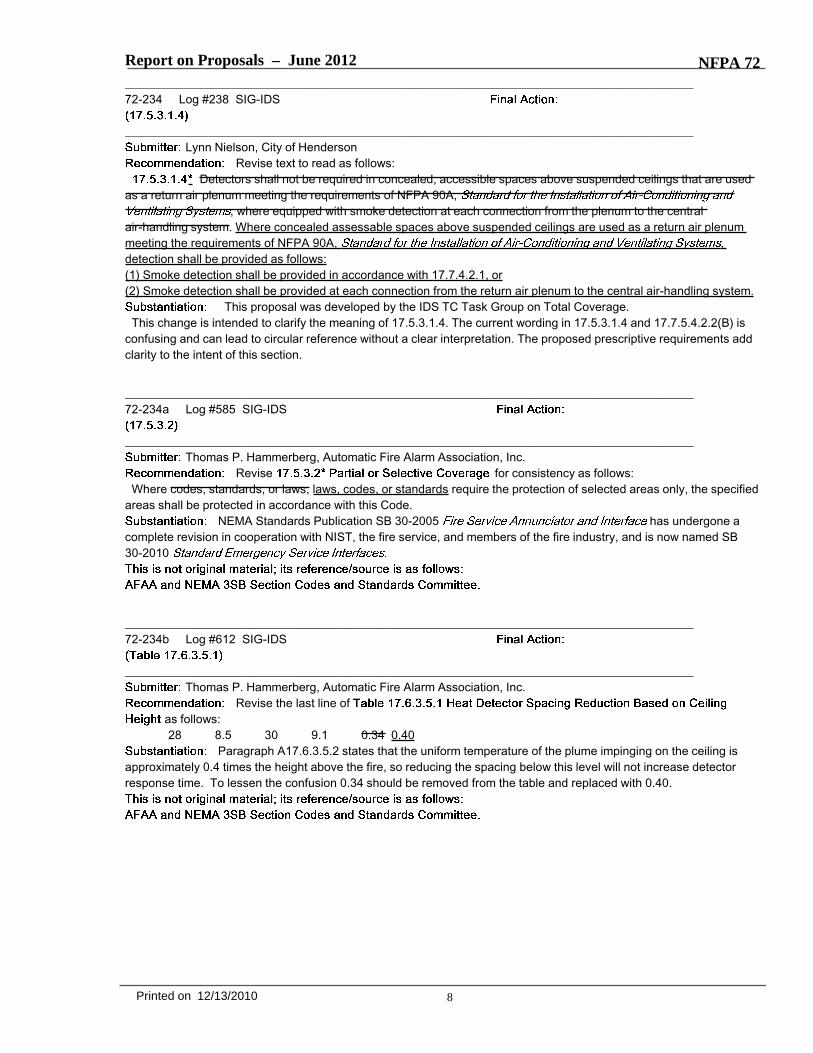
Report on Proposals – June 2012 NFPA 72_______________________________________________________________________________________________72-234 Log #238 SIG-IDS
_______________________________________________________________________________________________Lynn Nielson, City of Henderson
Revise text to read as follows:Detectors shall not be required in concealed, accessible spaces above suspended ceilings that are used
as a return air plenum meeting the requirements of NFPA 90A,, where equipped with smoke detection at each connection from the plenum to the central
air-handling system. Where concealed assessable spaces above suspended ceilings are used as a return air plenummeeting the requirements of NFPA 90A, ,detection shall be provided as follows:(1) Smoke detection shall be provided in accordance with 17.7.4.2.1, or(2) Smoke detection shall be provided at each connection from the return air plenum to the central air-handling system.
This proposal was developed by the IDS TC Task Group on Total Coverage.This change is intended to clarify the meaning of 17.5.3.1.4. The current wording in 17.5.3.1.4 and 17.7.5.4.2.2(B) is
confusing and can lead to circular reference without a clear interpretation. The proposed prescriptive requirements addclarity to the intent of this section.
_______________________________________________________________________________________________72-234a Log #585 SIG-IDS
_______________________________________________________________________________________________Thomas P. Hammerberg, Automatic Fire Alarm Association, Inc.
Revise for consistency as follows:Where codes, standards, or laws, laws, codes, or standards require the protection of selected areas only, the specified
areas shall be protected in accordance with this Code.NEMA Standards Publication SB 30-2005 has undergone a
complete revision in cooperation with NIST, the fire service, and members of the fire industry, and is now named SB30-2010
_______________________________________________________________________________________________72-234b Log #612 SIG-IDS
_______________________________________________________________________________________________Thomas P. Hammerberg, Automatic Fire Alarm Association, Inc.
Revise the last line ofas follows:28 8.5 30 9.1 0.34 0.40
Paragraph A17.6.3.5.2 states that the uniform temperature of the plume impinging on the ceiling isapproximately 0.4 times the height above the fire, so reducing the spacing below this level will not increase detectorresponse time. To lessen the confusion 0.34 should be removed from the table and replaced with 0.40.
8Printed on 12/13/2010

Report on Proposals – June 2012 NFPA 72_______________________________________________________________________________________________72-234c Log #613 SIG-IDS
_______________________________________________________________________________________________Thomas P. Hammerberg, Automatic Fire Alarm Association, Inc.
Remove the first two columns (text and values) of Table 17.6.3.5.1.
****Insert Table 17.6.3.5.1 Here****
This table has been a source of confusion. Values for the ceiling height repeat in the in the first andthird columns. If the user is not careful they will pick the improper spacing factor. In an example with a 20 ft ceilingheight the spacing factor of 0.58 may be used when the correct value of 0.64 should be used.
9Printed on 12/13/2010

72/L613/Tb 17.6.3.5.1/A2012/ROP
Table 17.6.3.5.1 Heat Detector Spacing Reduction Based on Ceiling Height
Ceiling Height Above
Ceiling Height Up To
And Including
Multiply Listed
Spaced By
ft m ft m 0 0 10 3.0 1.00 10 3.0 12 3.7 0.91 12 3.7 14 403 0.84 14 403 16 409 0.77 16 4.9 18 5.5 0.71 18 5.5 20 6.1 0.64 20 6.1 22 6.7 0.58 22 6.7 24 7.3 0.52 24 7.3 26 7.9 0.46 26 7.9 28 8.5 0.40 28 8.5 30 9.1 0.34

Report on Proposals – June 2012 NFPA 72_______________________________________________________________________________________________72-235 Log #16 SIG-IDS
_______________________________________________________________________________________________Stephen J. DiGiovanni, Clark County Fire Department
Revise text to read as follows:17.6.3.5.2 Spacing Minimum. The minimum spacing of heat detectors shall not be required to be less than 0.4 times
the height of the ceiling. Where heat detectors are installed more than 30 feetabove the floor below, the spacing between heat detectors shall be determined by an engineering analysis.
The base code provides incorrect guidance regarding spacing of heat detectors. The proposalattempts to remove the 0.4 factor, and replace it with code language requiring an engineering analysis for ceiling heightsexceeding 30 feet.
The annex to Section 17.6.5.3.5.2 states that “the width of uniform temperature of the plume when it impinges theceiling is approximately 0.4 times the height above the fire”. The 0.4 factor is a good estimation for the visible plume ofa fire, but is not a good estimation for the heat plume. This factor is used in Appendix B Figure 4.9.1, referencingspacing methods for projected beam detectors, which is appropriate until stratification occurs. However, use of thisfactor is not appropriate for heat-sensing devices, such as heat detectors. Temperature decays as ceiling heightincreases, whereas the 0.4 factor increases as ceiling height increases; this is inherently inconsistent and shows whythe 0.4 is not appropriate.
There are three factors that need to be addressed. First, as ceiling height increases, plume temperature at the plumecenterline decreases. Thus, heat detector performance worsens as ceiling height increases. Second, a plume does nothave uniform temperature across the width of the visible plume. Maximum temperature is seen at the plume centerline,but the temperature inside the plume decays away from the plume centerline. The plume temperature decays toapproximately one-half of the centerline temperature at a distance 0.1 times the height away from the plume centerline.Please note that his excess temperature width is exactly half of the visible plume width. Third, as the heated gasesimpinge on the ceiling and travel away from the centerline, the temperatures decay the further the gases have to travel.Due to these three factors, the use of the 0.4 factor is not appropriate for heat detector spacing.
Factor #1: Plume centerline temperature decreases as the ceiling gets taller. This temperature is given by correlationsdeveloped by Heskestad and presented in various forms (SFPE Handbook, 2nd Edition, pgs 2-9 through 2-19), notablyadopted by Klote and Milke as Formula 10.19 in Design of Smoke Management Systems. In all of the forms of theformula, plume centerline temperature is inversely exponentially proportional to ceiling height, at a negative exponentialrate of 5/3. For example, if the ceiling height between two applications is doubled, the plume centerline temperature isreduced by over two-thirds. Due to the lower temperatures, heat detector performance is hindered due to taller ceilingsheights. In contrast, in using the 0.4 factor, if the ceiling height is doubled, the allowed spacing between heat detectorsis doubled as well. This is only appropriate if heat detector performance is expected to be better with increased ceilingsheights, but this is not true.
Factor #2: Contrary to the annex material to Section 17.6.5.3.5.2, plumes do not have uniform temperature at ceilingimpingement, and certainly do not appreciably maintain temperatures at the 0.4 factor. Again, temperatures within theplume away from the centerline are provided by formulae developed by Heskestad. This formula is also adopted byKlote and Milke, as formula 10.18. From these formulae, plume temperature will reduce to one-half of the centerlinetemperature at a distance away from the plume centerline of approximately 10% of the ceiling height. This would lead toan approximate factor of 0.2, and not 0.4, and would also indicate that plume temperature is in fact not uniform acrossthe plume.
Factor #3: As the plume impinges a ceiling, a ceiling jet is formed. This ceiling jet heats the heat-sensing deviceprimarily through convection. The further away one measures from the plume centerline, the greater the temperaturedecay within the ceiling jet. In the SFPE chapter by David Evans (SFPE Handbook, 2nd Edition, pgs 2-32 through 2-39)there are two approximations for temperature decay away from the centerline, one from Alpert and one from Heskestadand Delichatsios. The Alpert approximations showed no temperature decay up to a factor of 0.36 (near the 0.4, but stillnot as liberal as 0.4), whereas the Heskestad/Delichatsios approximations showed immediate decay at a factorexceeding 0.2. Both approximations indicate that the 0.4 factor is too liberal and does not address temperature decay.
This proposal seeks to remove the 0.4 factor found in Section 17.6.3.5.2, as no basis is found to continue its use. Infact, there is significant evidence that the actual factor, if one is used, should be no greater than 0.2. One item toconsider is that the use of any of these factors, whether it be 0.4, 0.36, or 0.2, does not incorporate the effects of tallceiling heights. For this reason, code language is proposed that requires an engineering analysis for heat detectorsplaced on ceilings over 30 feet in height.If the committee agrees to this code proposal, the existing associated appendix material needs to be deleted.
10Printed on 12/13/2010

Report on Proposals – June 2012 NFPA 72
_______________________________________________________________________________________________72-236 Log #17 SIG-IDS
_______________________________________________________________________________________________Stephen J. DiGiovanni, Clark County Fire Department
Add text to read as follows:17.7.3.1.3 If the intent is to protect against a specific hazard, and the detectors are not otherwise required by this code
or other applicable codes, the detector(s) shall be permitted to be installed closer to the hazard in a position where thedetector can intercept the smoke.
The intent of this proposal is to more clearly define where this code language is applicable, to addressonly those situations where additional protection is being provided. The base code language seems to imply that smokedetectors must be allowed to be installed outside of its listings and other code requirements regarding device location,so long as the argument is made that the detector is closer to a specific hazard. The rest of the base code does notprohibit placing a detector closer to a hazard, but the detector location must still comply with requirements such asdistance below a ceiling and horizontal coverage area limitations. For instance, for area with tall ceilings (See Section21.3.5 for reference to a “tall ceiling”), past practice has allowed for the installation of the smoke detector on the wall,more than 12 inches below the ceiling, just above the hazard being protected. Installing a detector in this locationignores the way that smoke travels, and essentially provides no protection for the hazard until smoke has filled theceiling and has banked down to wherever the device is located. This process delays the response time of the detector,limiting or eliminating any protection that the detector should have provided. It is imperative to limit this code section sothat base code mandates that required detectors are located in accordance with the device location requirements foundelsewhere in the code.
_______________________________________________________________________________________________72-237 Log #536 SIG-IDS
_______________________________________________________________________________________________Robert P. Schifiliti, R. P. Schifiliti Associates, Inc.
Revise existing 17.7.3.2.3 as follows:17.7.3.2.3 On smooth ceilings, spacing for spot-type smoke detectors shall be in accordance with 17.7.3.2.3.1 through
17.7.3.2.3.5 17.7.3.2.3.4.Replace existing 17.7.3.2.3.1 as follows:17.7.3.2.3.1* In the absence of specific performance-based design criteria, one of the following requirements shall
apply:(1) The distance between smoke detectors shall not exceed a nominal spacing of 30 ft (9.1 m) and there shall be
detectors within a distance of one-half the nominal spacing, measured at right angles from all walls or partitionsextending upward to within the top 15 percent of the ceiling height.
(2) All points on the ceiling shall have a detector within a distance equal to or less than 0.7 times the nominal 30 ft (9.1m) spacing (0.7S).
Delete existing 17.7.3.2.3.5.17.6.3.1.1 permits designers and installers of heat detection systems to use a linear spacing the
protection radius rule (0.7 S). As currently written, 17.7.3.2.3 requires compliance with 17.7.3.2.3.117.7.3.2.3.5. Since 17.7.3.2.3.1 requires spacing no more than 30 ft (linear), many AHJs will not allow the use of theprotection radius rule (0.7S) in narrow spaces such as corridors.
11Printed on 12/13/2010

Report on Proposals – June 2012 NFPA 72_______________________________________________________________________________________________72-238 Log #132 SIG-IDS
_______________________________________________________________________________________________Andrew B. Woodward, Arup
Add text to read as follows:17.7.3.3.1 Where a beam is located at the peak, spot-type smoke detector(s) shall be located at the bottom of the
beam that is at the peak of the ceiling.The requirements for beam ceilings do not clearly address the location of spot-type smoke detectors
where there is a ridge beam located at the peak of a ceiling. This requirement provides clarification for locatingspot-type smoke detectors under this condition.
_______________________________________________________________________________________________72-239 Log #121 SIG-IDS
_______________________________________________________________________________________________Abhay Nadgir, Kidde-Fenwal, Inc.
Add text to read as follows:Each sampling port of an air sampling–type smoke detector shall be treated as a spot-type detector for the purpose of
location and spacing. While multiple sensitivity levels are permitted, each air sampling–type smoke detector shall betreated as a single detector for the purpose of reporting alarm, trouble and supervisory events.
Many if not most Air Sampling detectors on the market today provide multiple alarm levels (pre-alarm,alarm-1, alarm-2, etc). The additional text is intended to clarify that, should they occur, the multiple alarms are from thesame detector and to ultimately preclude the possibility of the multiple alarms being misconstrued as alarms fromdifferent detectors.
_______________________________________________________________________________________________72-239a Log #586 SIG-IDS
_______________________________________________________________________________________________Thomas P. Hammerberg, Automatic Fire Alarm Association, Inc.
Add new text as follows and renumber subsequent paragraphs:17.7.3.6.2 While multiple sensitivity levels are permitted, each air sampling–type smoke detector shall be treated as a
single detector for the purpose of reporting alarm, trouble and supervisory events.While the code is clear as to the treatment of each sampling port for the purpose of location and
spacing, there is need to clarify required treatment for the purpose of reporting.
12Printed on 12/13/2010

Report on Proposals – June 2012 NFPA 72_______________________________________________________________________________________________72-240 Log #197 SIG-IDS
_______________________________________________________________________________________________Jack Parow, International Association of Fire Chiefs (IAFC) / Rep. FLSS of the IAFC and the CSAA
Add new text to read as follows:Detectors placed in environmental air ducts or plenums shall be supervisory devices.
A number of proposals have been submitted to the NFPA 72® project for this cycle to assist indecreasing the number of unwanted or nuisance alarms
Under the present code, duct detectors may cause either an alarm or supervisory signals. Duct detectors are notintended to be a life safety device, nor are they intended to provide area detection. Because of the areas that they areinstalled within, they are prone to unwanted or nuisance alarms. This proposal if accepted would require that ductdetectors that are located within environmental are ducts or plenums only be supervisory devices.
The reduction of unwanted or nuisance alarms are a central point of the International Association of Fire Chiefs (IAFC)position statement on Eliminating Unwanted and Nuisance Fire Alarm Activations. A copy of this paper may be found athttp://www.iafc.org/associations/4685/files/IAFCposition_EliminatingUnwantedandNuisanceFireAlarmActivations.pdf
_______________________________________________________________________________________________72-241 Log #199 SIG-IDS
_______________________________________________________________________________________________Jack Parow, International Association of Fire Chiefs (IAFC) / Rep. FLSS of the IAFC and the CSAA
Add new text to read as follows:Smoke detectors used solely for closing dampers or for heating, ventilating, and air-conditioning system
shutdown shall not activate the building evacuation alarm. These detectors shall be supervisory devices.A number of proposals have been submitted to the NFPA 72® project for this cycle to assist in
decreasing the number of unwanted or nuisance alarmsUnder the present code, duct detectors may cause either an alarm or supervisory signals. NFPA 90A, section
6.4.4.2.1 does not require smoke detectors used solely for closing dampers or for heating, ventilating, andair-conditioning system shutdown to activate the building evacuation alarm. Duct detectors used in these applicationsare not intended to be life safety devices, nor are they intended to provide open area protection. Because of the areasthat they are installed within, they are prone to unwanted or nuisance alarms. This proposal if accepted would requirethat duct detectors that are located within air duct systems only be supervisory devices.
The reduction of unwanted or nuisance alarms are a central point of the International Association of Fire Chiefs (IAFC)position statement on A copy of this paper may be found athttp://www.iafc.org/associations/4685/files/IAFCposition_EliminatingUnwantedandNuisanceFireAlarmActivations.pdf.
Note: If the above proposal is submitted it should not be necessary to submit the duct detector changes proposed forSections 17.7.4.2.2 and 17.7.5.5.5.
13Printed on 12/13/2010
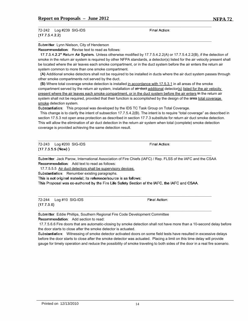
Report on Proposals – June 2012 NFPA 72_______________________________________________________________________________________________72-242 Log #239 SIG-IDS
_______________________________________________________________________________________________Lynn Nielson, City of Henderson
Revise text to read as follows:Unless otherwise modified by 17.7.5.4.2.2(A) or 17.7.5.4.2.2(B), if the detection of
smoke in the return air system is required by other NFPA standards, a detector(s) listed for the air velocity present shallbe located where the air leaves each smoke compartment, or in the duct system before the air enters the return airsystem common to more than one smoke compartment.
Additional smoke detectors shall not be required to be installed in ducts where the air duct system passes throughother smoke compartments not served by the duct.
Where total coverage smoke detection is installed in accordance with 17.5.3.1 in all areas of the smokecompartment served by the return air system, installation of air duct additional detector(s) listed for the air velocitypresent where the air leaves each smoke compartment, or in the duct system before the air enters in the return airsystem shall not be required, provided that their function is accomplished by the design of the area total coveragesmoke detection system.
This proposal was developed by the IDS TC Task Group on Total Coverage.This change is to clarify the intent of subsection 17.7.5.4.2(B). The intent is to require “total coverage” as described in
section 17.5.3 not open area protection as described in section 17.7.3 substitute for return air duct smoke detection.This will allow the elimination of air duct detection in the return air system when total (complete) smoke detectioncoverage is provided achieving the same detection result.
_______________________________________________________________________________________________72-243 Log #200 SIG-IDS
_______________________________________________________________________________________________Jack Parow, International Association of Fire Chiefs (IAFC) / Rep. FLSS of the IAFC and the CSAA
Add text to read as follows:17.7.5.5.5 Air duct detectors shall be supervisory devices.
Renumber existing paragraphs.
_______________________________________________________________________________________________72-244 Log #10 SIG-IDS
_______________________________________________________________________________________________Eddie Phillips, Southern Regional Fire Code Development Committee
Add section to read:17.7.5.6.6 Fire doors that are automatic-closing by smoke detection shall not have more than a 10-second delay before
the door starts to close after the smoke detector is actuated.Witnessing of smoke detector activated doors on some field tests have resulted in excessive delays
before the door starts to close after the smoke detector was actuated. Placing a limit on this time delay will providegauge for timely operation and reduce the possibility of smoke traveling to both sides of the door in a real fire scenario.
14Printed on 12/13/2010

Report on Proposals – June 2012 NFPA 72_______________________________________________________________________________________________72-245 Log #110 SIG-IDS
_______________________________________________________________________________________________Merton W. Bunker, Jr., US Department of State
Add the following to the header for Table 17.7.6.3.3.1:“(Not to be Used for Under-Floor or Above-Ceiling spaces).”
Table 17.7.6.3.3.1 and Figure 17.7.6.3.3.1 essentially contain the same data. Figure 17.7.6.3.3.1contains this parenthetical statement after the heading. This proposed change only seeks to provide consistencybetween the two.
_______________________________________________________________________________________________72-246 Log #249 SIG-IDS
_______________________________________________________________________________________________Vic Humm, Vic Humm & Associates
Add new 17.7.7.5 to read as follows:Video Imaging Smoke Detection system that requires the use of interior or exterior facility lighting to maintain functional
operation, then he lighting load shall be include in the secondary power requirements as outlined in section 10.5.6Typically video systems will use the emergency lighting referred, too as night lighting. The energy
sources supplying this lighting may optionally have 90 minutes of emergency power. This requirement will maintain theoperation of the system during a power outage.
_______________________________________________________________________________________________72-247 Log #125 SIG-IDS
_______________________________________________________________________________________________Jon D. Miller, Detector Electronics Corp.
Revise text as follows :"Gas detection equipment shall be listed for detection of the specific gas or vapor to be encountered. In applications in
which the gas to be detected is of a gas that differs from the gas used in the process of listing or approval. thecharacterization of the detector shall be adjusted in accordance with the manufacturer's published instructions."
All gas detectors will encounter gases other than those intended for it to detect. Combustible gasdetectors are intended to detect a range of hydrocarbon gases. Usually Methane is the major component of the gasstream and calibration is performed with a methane test gas. Where other gases such as Propane or Pentane areexpected in significant quantity, calibration is performed to enhance the detection of those gases. Gas detectors are alsoevaluated for the impact of other gases in accordance with the relevant gas performance standards. Where other gasesmight be present that have a significant impact on the operation of a particular gas detector, an alternate choice of gasdetector should be made. Gases present (in combination with the intended gas) which are not intended to be detectedshould not be required to be included in the listing or approval. The gas detection requirement should be equivalent tothe fire detector requirement of Clause 17.8.3.2.4.
15Printed on 12/13/2010

Report on Proposals – June 2012 NFPA 72_______________________________________________________________________________________________72-248 Log #126 SIG-IDS
_______________________________________________________________________________________________Jon D. Miller, Detector Electronics Corp.
Revise text to read as follows:Any gas detection systems installed on a fire alarm system shall comply with all the applicable requirements of
Chapters 1,10, 14, 17, and 23 of this Code. For gas detection equipment. only the primary signaling circuit is required tobe classified. For analog gas detection equipment. a loss of performance of the analog signal circuit shall not exceed therequirements of ANS/IISA-12.13.01 , ANSI/ISA-12 .13.04 or ANSI/ISA-92.00.01 during ground fault condition.
1) Gas detection equipment includes ancillary circuits (eg. calibration line circuit, HART communicationcircuit, etc.) which may initiate special routines during ground fault condition introducing a change in analog signal staterather than trouble signal. Special routines are subject to evaluation in accordance with the relevant gas performancestandards (ANSI/ISA-12.13.01, ANSI/ISA-12.13.04 or ANSI/ISA-92.00.01), and the related ancillary circuits should bepermitted to operate as intended under a ground fault condition.
2) For analog (4-20mA) signaling gas detection equipment, the analog signal circuit may be negatively affected(increase or decrease of analog signal) during a ground fault condition. Although the signal may be affected, the signalshould not exceed the accuracy requirements of the relevant gas performance standards (ANSI/ISA-12.13.01,ANSI/ISA-12.13.04 or ANSI/ISA-92.00.01).
_______________________________________________________________________________________________72-249 Log #202 SIG-IDS
_______________________________________________________________________________________________Jack Parow, International Association of Fire Chiefs (IAFC) / Rep. FLSS of the IAFC and the CSAA
Revise text to read as follows:17.12.2* Activation of the initiating device shall occur between 45 seconds and within 90 seconds of waterflow at the
alarm-initiating device when flow occurs that is equal to or greater than that from a single sprinkler of the smallest orificesize installed in the system.
A number of proposals have been submitted to the NFPA 72® project for this cycle to assist indecreasing the number of unwanted or nuisance alarms
Under the present code, vane flow switches must trip within 90 seconds of the flow of water. There is no minimum timerequirement. Because of this, there are some jurisdictions that require a trip of the flow switch within thirty or evenfifteen seconds of the start of the flow. This creates a problem with trips that may be caused by a water surge.
This proposal still retains the requirement that the trip must occur within 90 seconds, but would require that the systemwould not trip prior to 45 seconds of the flow of water. This would eliminate a large percentage of unwanted or nuisancealarms caused by water surges.
The revisions to the Annex material provide additional information for the users of NFPA 72®.The reduction of unwanted or nuisance alarms are a central point of the International Association of Fire Chiefs (IAFC)
position statement on Eliminating Unwanted and Nuisance Fire Alarm Activations. A copy of this paper may be found athttp://www.iafc.org/associations/4685/files/IAFCposition_EliminatingUnwantedandNuisanceFireAlarmActivations.pdf
16Printed on 12/13/2010

Report on Proposals – June 2012 NFPA 72_______________________________________________________________________________________________72-250 Log #435 SIG-IDS
_______________________________________________________________________________________________Robert P. Schifiliti, R. P. Schifiliti Associates, Inc.
Add New 17.14.3, 17.14.4 and A.17.14.4 and renumber all following paragraphs:17.14.3 Listed manual initiating devices shall be permitted to be single action or double action.17.14.4 * Listed protective covers shall be permitted to be installed over single or double action manual initiatingdevices.A. 17.14.4 Protective covers, also called pull station protectors can be installed over manual initiating devices to providemechanical protection, environmental protection and to reduce the likelihood of accidental or malicious activation. Theunits must be listed to ensure that they do not hinder the operation of the pull stations and to ensure that they meetaccessibility requirements for activation by persons with physical disabilities. The code explicitly permits installing themover single or double action manual boxes. When installed over a double action box, the assembly effectively becomesa triple action box. Some units include battery operated audible warning signals that have been shown to determalicious activations. To be effective, it is important that the regular staff or occupants be aware of the sound andinvestigate immediately in order to catch someone who might otherwise activate the box without cause or to ensure thatthe box is activated if there is a legitimate reason.
The use of these devices has been very effective at reducing nuisance alarms. However, NFPA staffcontinues to get questions about whether they are permitted and whether a double action station can be made into atriple action station by inclusion of a protective cover. This code text makes it clear that they are permitted and that theymust be listed for the purpose.
_______________________________________________________________________________________________72-251 Log #204 SIG-IDS
_______________________________________________________________________________________________Jack Parow, International Association of Fire Chiefs (IAFC) / Rep. FLSS of the IAFC and the CSAA
Add text to read as follows:17.14.5 Manual fire alarm boxes shall be enclosed within a listed means of mechanical protection.
None given.
_______________________________________________________________________________________________72-252 Log #332 SIG-IDS
_______________________________________________________________________________________________Scott Lacey, Lacey Fire Protection Engineering
Add text to read as follows:17.16.1.3 Fully close the valve and verify signal status throughout closure. The off-normal signal shall not be restored
at any valve position except normal.Manufacturers instruction manual such as System Sensor OSY2 Gate Valve Switch only require
turning the valve 2 turns or one-fifth of the rotation as this is the clear requirement of the code. This is not sufficient asnearly every field valve I have tested will restore to normal condition when fully closed and the roller is in the threads. Itis essential that this paragraph be clarified to require full closure of the valve with signal status verified through closure.
17Printed on 12/13/2010

Report on Proposals – June 2012 NFPA 72_______________________________________________________________________________________________72-253 Log #331 SIG-IDS
_______________________________________________________________________________________________Scott Lacey, Lacey Fire Protection Engineering
Add text to read as follows:17.16.1.5* A supervisory switch that incorporate rollers over valve stem threads shall have the roller diameter sized a
minimum of 250% larger than the thread width.A.17.16.1.5 Rollers that are not large enough will drop down into the valve stem threads just as the roller is intended to
drop into the manufacturer’s grove. In such condition the valve can be fully closed with the tamper switch indicating anormal condition. Providing a larger roller limits the movement down into the threads. An example would be a valvestem with threads of 0.20” width should use a roller of 0.50” in diameter. Groove in valve stem for normal status shall belarge enough to accommodate roller.
During commissioning we find that more than 80% of systems will indicate normal condition when thevalve is fully closed and the rod is within the threads. The tolerance of a small roller going into the threads vs. themanufacturer’s notch is so close that it is very difficult and sometimes impossible to get a switch to not show normalcondition with valve closed. Potter provided alternate rollers for testing and it was found that changing to a 0.500” rollerwould address the problem. Due to importance of this item and due to other manufacturers, it is felt necessary to be acode item. This issue was reported to UL in January 2009 for potter and System Sensor switches and the problem stillexists. This is an easy fix to a major problem that has been technically validated with larger roller.
Note: Supporting material is available for review at NFPA Headquarters.
_______________________________________________________________________________________________72-254 Log #322 SIG-IDS
_______________________________________________________________________________________________Thomas J. Parrish, Telgian
Revise text to read as follows:17.16.2.2.2 Dry Type Pipe Sprinkler.(1) A pressure supervisory signal-initiating device for a dry pipe sprinkler system shall indicate both high- and low
-pressure conditions.(2) The off-normal signal shall be initiated when the pressure increases or decreases by 10 psi (70 kPa).
The definition of a dry pipe sprinkler system from NFPA 13 is 3.4.5 Dry Pipe Sprinkler System. Asprinkler system employing automatic sprinklers that are attached to a piping system containing air or nitrogen underpressure, the release of which (as from the opening of a sprinkler) permits the water pressure to open a valve known asa dry pipe valve, and the water then flows into the piping system and out the opened sprinklers.
A dry type sprinkler is an individual device as defined in NFPA 13 as follows:3.6.3.2* Dry Sprinkler. A sprinkler secured in an extension nipple that has a seal at the inlet end to prevent water from
entering the nipple until the sprinkler operates.My proposal will correct the incorrect terminology from the title of this section. I have also added spaces between Dry
and Pipe as well as Low and Pressure.
18Printed on 12/13/2010

Report on Proposals – June 2012 NFPA 72_______________________________________________________________________________________________72-255 Log #321 SIG-IDS
_______________________________________________________________________________________________Thomas J. Parrish, Telgian
Add new text to read as follows:17.16.5.1 Room temperature supervisory device shall be installed in any room or enclosure that houses water based
fire protection devices in areas that are exposed to freezing conditions.The provision is in the code to require a low temperature device to initiate both a low temperature and
a return to normal signal to the fire alarm and signaling system. There is no requirement currently to install the devicewe are requiring the signal from. This provision would require a low temperature device be installed in locations that aresubject to freezing conditions.
_______________________________________________________________________________________________72-578 Log #240 SIG-IDS
_______________________________________________________________________________________________Lynn Nielson, City of Henderson
Add text to read as follows:A.17.5.3.1.4 Total coverage requires that a fire above the suspended ceiling be detected. Detector spacing and
location for above ceiling spaces are addressed in 17.7.3.5.2. If that above-ceiling space is used as a air return plenum,this detection can be provided either by smoke detectors placed in accordance with 17.7.4.2.1 or where the air leavesthe smoke compartment in accordance with 17.7.5.4.2.2.
This proposal was developed by the IDS TC Task Group on Total Coverage.This change is intended to clarify the meaning of 17.5.3.1.4. The current wording in 17.5.3.1.4 and 17.7.5.4.2.2(B) is
confusing and can lead to circular reference without a clear interpretation. The proposed prescriptive requirements addclarity to the intent of this section.
_______________________________________________________________________________________________72-578a Log #608 SIG-IDS
_______________________________________________________________________________________________Thomas P. Hammerberg, Automatic Fire Alarm Association, Inc.
Revise A.17.6.3.5.2 as follows:The width of uniform temperature of the plume when it impinges on the ceiling is approximately 0.4 times the height
above the fire, so reducing the spacing below this level will not increase response time. For example, a detector with alisted spacing of 15 ft (4.6 m) or 225 ft2 (21 m2) need not be spaced closer than 12 ft (3.7 m) on a 30 ft 9.1 m) ceiling.,even though Table 17.6.3.5.1 states that the spacing should be 0.34 x 15 ft (0.34 x 4.6 m), which equals 5.1 ft (1.6 m).
If our proposal to change .34 to .4 on Table 17.6.3.5.1 is accepted, this will correlate with it byremoving the reference to .34 in the second sentence.
19Printed on 12/13/2010

Report on Proposals – June 2012 NFPA 72_______________________________________________________________________________________________72-579 Log #475 SIG-IDS
_______________________________________________________________________________________________Daniel G. Decker, Safety Systems, Inc.
Delete the following text:A.17.7.3.1.4 There are some applications that do not require full area protection, but do require detection, to initiate
action when specific objects or spaces are threatened by smoke or fire, such as at elevator landings that have ceilings inexcess of 15 ft (4.6 m) and for protection of fire alarm control units. In high-ceiling areas, to achieve the desiredinitiation, such as for elevator recall and protection of fire alarm control units (FACUs), detection should be placed on thewall above and within 60 in. (1.52 m) from the top of the elevator door(s) or FACU.
Based on the Fundamentals TC action on Comment 72-150 in the 2010 cycle, the smoke detectorabove the control panel is required to activate prior to the sprinkler system activating, as water from a dischargedsprinkler head could incapacitate the control panel. Consequently, it is necessary to locate the smoke detector incompliance with 17.7.3.2.1 and locate the smoke detector on the ceiling or on the wall within 12 inches of the ceiling.Locating a smoke detector on a wall 6 ft from the top of the control unit does nothing to assure that the smoke will reachthe detector prior to sprinkler activation.
_______________________________________________________________________________________________72-580 Log #120 SIG-IDS
_______________________________________________________________________________________________Abhay Nadgir, Kidde-Fenwal, Inc.
Revise text to read as follows:The air sampling–type detector system should be able to withstand dusty environments by either air filtering, or
electronic discrimination of particle size, other listed methods or combinations thereof. The detector should be capableof providing optimal time delays of alarm outputs to eliminate nuisance alarms due to transient smoke conditions. Thedetector should also provide facilities for the connection of monitoring equipment for the recording of background smokelevel information necessary in setting alert and alarm levels and delays.
The text in the current code appears to limit filtering of the incoming air to one of two methods. Thechange will (i) remove the limitation, (ii) permit a combination of the two currently acceptable methods and (iii) imposethe requirement that any new method(s) be listed for the purpose.
_______________________________________________________________________________________________72-580a Log #604 SIG-IDS
_______________________________________________________________________________________________Thomas P. Hammerberg, Automatic Fire Alarm Association, Inc.
Revise text to read as follows:A.17.7.3.6.6 The air sampling–type detector system should be able to withstand dusty environments by either air
filtering, or electronic discrimination of particle size, a combination thereof or other listed methods. The detector shouldbe capable of providing optimal time delays of alarm outputs to eliminate nuisance alarms due to transient smokeconditions. The detector should also provide facilities for the connection of monitoring equipment for the recording ofbackground smoke level information necessary in setting alert and alarm levels and delays.
The current text limits of filtering to one of two methods. The change will remove this limitation.
20Printed on 12/13/2010

Report on Proposals – June 2012 NFPA 72_______________________________________________________________________________________________72-581 Log #198 SIG-IDS
_______________________________________________________________________________________________Jack Parow, International Association of Fire Chiefs (IAFC) / Rep. FLSS of the IAFC and the CSAA
Add new text to read as follows:These detectors are not intended for life safety but rather for the shutting down of air-handling systems.
The spaces that these detectors are located are subject to dust and other particles that a smoke detector may beactivated by. Detectors that are programmed as alarm devices could be prone to transmitting nuisance alarms.
Renumber existing paragraphs.
_______________________________________________________________________________________________72-582 Log #241 SIG-IDS
_______________________________________________________________________________________________Lynn Nielson, City of Henderson
Revise text to read as follows:Detectors listed for the air velocity present can be permitted to be installed at the opening where the
return air enters the common return air system. The detectors should be installed up to 12 in. (300mm)in front of orbehind the opening and spaced according to the following opening dimensions
:(1)(a) Up to 36 in. (910 mm) — One detector centered in opening(b) Up to 72 in. (1.83 m) —Two detectors located at the one-quarter points of the opening(c) Over 72 in. (1.83 m) — One additional detector for each full 24 in. (610 mm) of opening
(2) The number and spacing of the detector(s) in the depth (vertical) of the opening should be the same asthose given for the width (horizontal) in A.17.7.5.4.2.2(1).
(3) Detectors should be oriented in the most favorable position for smoke entry with respect to the directionof airflow. The path of a projected beam–type detector across the return air openings should be considered equivalent incoverage to a row of individual detectors.
Additional duct smoke detection is not required where the air leaves each smoke compartment or in the duct systembefore the air enters the return air system in the return air of a smoke compartment provided with total (complete) smokedetection compliant with 17.5.3 because the addition of duct smoke detection would essentially not add any substantialdetection benefit.
This proposal was developed by the IDS TC Task Group on Total Coverage.This change will clarify the intent of the code modification allowed by using subsection 17.7.5.4.2(B). The term “area
detection system” is not defined. The term “total coverage” is defined in section 17.5.3. The intent of subsection17.7.5.4.2(B) is to allow elimination of the air duct detector in the return air system when the smoke detection provided iscomplete or total coverage achieving the same result.
21Printed on 12/13/2010

Report on Proposals – June 2012 NFPA 72_______________________________________________________________________________________________72-583 Log #201 SIG-IDS
_______________________________________________________________________________________________Jack Parow, International Association of Fire Chiefs (IAFC) / Rep. FLSS of the IAFC and the CSAA
Add text to read as follows:A.17.7.5.5.5 These detectors are not intended for life safety but rather for the shutting down of air-handling systems.
The spaces that these detectors are located are subject to dust and other particles that a smoke detector may beactivated by. Detectors that are programmed as alarm devices could be prone to transmitting nuisance alarms
Renumber existing paragraphs
_______________________________________________________________________________________________72-584 Log #203 SIG-IDS
_______________________________________________________________________________________________Jack Parow, International Association of Fire Chiefs (IAFC) / Rep. FLSS of the IAFC and the CSAA
Revise text to read as follows:A.17.12.2 The waterflow device should be field adjusted so that an alarm is initiated no sooner than 45 seconds or no
more than 90 seconds after a sustained flow of at least 10 gpm (40 L/min). The retard being set to a minimum of 45seconds eliminates a number of nuisance alarms that may be caused by a water surge.
Features that should be investigated to minimize alarm response time include the following:(1) Elimination of trapped air in the sprinkler system piping(2) Use of an excess pressure pump(3) Use of pressure drop alarm-initiating devices(4) A combination thereof
Care should be used when choosing waterflow alarm-initiating devices for hydraulically calculated looped systems andthose systems using small orifice sprinklers. Such systems might incorporate a single point flow of significantly less than10 gpm (40 L/min). In such cases, additional waterflow alarm-initiating devices or the use of pressure drop-typewaterflow alarm-initiating devices might be necessary.
Care should be used when choosing waterflow alarm-initiating devices for sprinkler systems that use on–off sprinklersto ensure that an alarm is initiated in the event of a waterflow condition. On–off sprinklers open at a predeterminedtemperature and close when the temperature reaches a predetermined lower temperature. With certain types of fires,waterflow might occur in a series of short bursts of a duration of 10 seconds to 30 seconds each. An alarm-initiatingdevice with retard might not detect waterflow under these conditions. An excess pressure system or a system thatoperates on pressure drop should be considered to facilitate waterflow detection on sprinkler systems that use on–offsprinklers.
Excess pressure systems can be used with or without alarm valves. The following is a description of one type ofexcess pressure system with an alarm valve.
An excess pressure system with an alarm valve consists of an excess pressure pump with pressure switches to controlthe operation of the pump. The inlet of the pump is connected to the supply side of the alarm valve, and the outlet isconnected to the sprinkler system. The pump control pressure switch is of the differential type, maintaining the sprinklersystem pressure above the main pressure by a constant amount. Another switch monitors low sprinkler system pressureto initiate a supervisory signal in the event of a failure of the pump or other malfunction. An additional pressure switchcan be used to stop pump operation in the event of a deficiency in water supply. Another pressure switch is connectedto the alarm outlet of the alarm valve to initiate a waterflow alarm signal when waterflow exists. This type of system alsoinherently prevents false alarms due to water surges. The sprinkler retard chamber should be eliminated to enhance thedetection capability of the system for short duration flows.
No substantiation given.
22Printed on 12/13/2010

Report on Proposals – June 2012 NFPA 72_______________________________________________________________________________________________72-585 Log #205 SIG-IDS
_______________________________________________________________________________________________Jack Parow, International Association of Fire Chiefs (IAFC) / Rep. FLSS of the IAFC and the CSAA
Add text to read as follows:A.17.14.5 To reduce malicious alarms, manual fire alarm boxes placed within a listed enclosure prevent a number of
false alarms being generated. The listed covers also reduce alarms that may be caused by accidental contact. Theenclosure is to be listed for the manual fire alarm box that it is to be placed over.
Renumber existing paragraphs that follow.
_______________________________________________________________________________________________72-603 Log #21 SIG-IDS
_______________________________________________________________________________________________John F. Bender, Underwriters Laboratories Inc.
Revise text as follows:B.6.5 References(35) UL 268, , Underwriters Laboratories, Inc.,
Northbrook, IL, 2006 2009.Update referenced standard to most recent revision. UL 268 is the first publication of the common UL
and ULC standard for Smoke Detectors for Fire Alarm Systems. National differences are identified in the new standard.
_______________________________________________________________________________________________72-611 Log #24 SIG-IDS
_______________________________________________________________________________________________John F. Bender, Underwriters Laboratories Inc.
Revise text as follows:American National Standards Institute, Inc., 25 West 43rd Street, 4th floor, New York, NY
10036.ANSI/ASME A17.1a/CSA B44a, , 2008.ANSI/ATA 878.1, , 1999.ANSI/EIA 709.1, , 1999.ANSI/FM 3260,
2004.ANSI S3.2, , 1989, revised 1999.ANSI S3.41, , 1990, reaffirmed 2008.ANSI/UL 268, , 2006 2009. (SIG-IDS)ANSI/UL 464, 2003, revised 2008 2009. (SIG-NAS)ANSI/UL 521, , 1999, revised 2004 2010. (SIG-NAS)ANSI/UL 864, , 2003, revised 2006 2010.
(SIG-ECS, SIG-TMS)ANSI/UL 1638,
2001, revised 2008.ANSI/UL 1971, , 2002, revised 2008.
Update referenced standards to most recent revisions. UL 268 is the first publication of the commonUL and ULC standard for Smoke Detectors for Fire Alarm Systems. National differences are identified in the newstandard. UL 464 includes a new section for protective covers and accessories and a new jarring test, revises markingrequirements, outdoor use salt spray test, various test voltages, temperature tests, endurance test, and deletes the dusttest. ANSI/UL 521 updated the temperature test. UL 864 has been revised to include fail-safe fire release devices.
23Printed on 12/13/2010