Embed Size (px)
Citation preview

© ABBSlide 114-Nov-16
Advances in Grid EquipmentTransmission Shunt Compensation
Joe Warner, Electric Power Industry Conference (EPIC), November 15, 2016

© ABBSlide 214-Nov-16
Advances in Transmission Shunt Compensation
BoA: Book of Acronyms
MSC/MSR: Mechanically Switched Capacitor/Reactor
SVC: Static Var Compensator
TCR: Thyristor Controlled Reactor
TSR/TSC: Thyristor Switched Reactor/Capacitor
STATCOM: Static Synchronous Condenser
NPC: Neutral-Point Clamped
MMC: Multi-level Modular Converter
IGBT: Insulated-Gate Bipolar Transistor
Excerpt from the BoA

© ABBSlide 314-Nov-16
Shifting transmission system
Synchronous generation retirement
Penetration of distributed renewables and dynamic load
Resulting in
Weak networks with a resonance approaching fundamental frequency
Increased vulnerability to disturbance
Increased requirements for mitigation solutions
Advances in Transmission Shunt CompensationNetwork Challenges

© ABBSlide 414-Nov-16
Advances in Transmission Shunt CompensationNetwork Challenges
National Grid Electric, Ten Year Statement

© ABBSlide 514-Nov-16
Advances in Transmission Shunt Compensation
Network resonances are shifting due to system changes
Resonance frequencies and system damping affected by:
Number of un-tuned shunt capacitor banks (over-compensation)
Cable and T-line charging
Parallel FACTS and HVDC installations (filters)
System loading (active and reactive)
Network Challenges

© ABBSlide 614-Nov-16
Solutions:
Cheap and low-loss for steady-state compensation
Challenges:
Slow switch-in/out and discharge
Network dependent voltage step Δ𝑈𝑈𝑈𝑈 ≈
𝑄𝑄𝑆𝑆
Overcompensation leads to low network resonance and has resulted in inadvertent network collapse
𝑟𝑟 =𝑆𝑆𝑄𝑄
Advances in Transmission Shunt CompensationMechanically Switched Capacitors
52

© ABBSlide 714-Nov-16
Solutions:
Inertia increases system strength and provides fault current
Reactive power compensation without generating harmonics
Natural thermal overload capacity
Challenges:
Smaller output range ( < 100 MW)
Var support provided by automatic excitation control, medium speed
Maintenance
Losses
Advances in Transmission Shunt CompensationSynchronous Condensers

© ABBSlide 814-Nov-16
Solutions:
Fast, continuously variable output
Large sizes available ( > 400 Mvar)
Robust overvoltage capability
Configurable to maximize value
Challenges:
TCR generates harmonics
Filter design dependent on network harmonic impedances
Difficulty operating in a weak network
Output varies with 𝑉𝑉2
Advances in Transmission Shunt CompensationStatic Var Compensator (SVC)
´TCR TSR TSC Harmonic Filters
Static Var Compensator (SVC)

© ABBSlide 914-Nov-16
Three-level NPC concept Pulse Width Modulation
High Switching frequency (>1.5 kHz)
Maximum rating of 100 MVA
IGBT units in series
With IGBTS no voltage grading circuits (snubber circuits)
Common dc-link
Well suited for energy storage
High harmonic generation
Substantial power losses
Advances in Transmission Shunt CompensationSTATCOM Converter Topologies
-
0
+
0 0.005 0.01 0.015 0.02 0.025 0.03 0.035 0.04-2
-1
0
1
2
t [s]
u1-u
2

© ABBSlide 1014-Nov-16
Chainlink MMC concept Cascaded H-bridges.
Modular in # of cells
1 cell = 4 semiconductors (V1 – V4)
Number depends on required output.
Distributed dc-link
Low switching frequency ( ~300 Hz)
Lower power losses
Advances in Transmission Shunt CompensationSTATCOM Converter Topologies
+−
Udc
+−
Udc
+−
Udc
+−
Udc
+ −U
dc+ −
Udc
+ −U
dc+ −
Udc
+− Udc
+− Udc
+− Udc
+− Udc
+−
Udc
+ −
V1
V2
V3
V4

© ABBSlide 1114-Nov-16
−+
+
−
Udc
+
−
Udc
Advances in Transmission Shunt CompensationSTATCOM – How MMC works
20 cells vs. 2 cells above

© ABBSlide 1214-Nov-16
Solutions:
Fast, continuously variable output
MMC configuration typically filterless
Operates in a weak network
Output varies directly with voltage
Small footprint
Challenges:
Limited overvoltage capability
Advances in Transmission Shunt Compensation
VSC
V’’syst
Vconv
+ VDC -
IindIcap
Vsyst
System Voltage
Converte Voltage
Capacitive Current
Inductive Current
XT
Static Synchronous Compensator (STATCOM)

© ABBSlide 1314-Nov-16
Advances in Transmission Shunt CompensationSVC vs. STATCOM Performance
I
V
Inductive OutputCapacitive Output 0
1.0
1.0 1.0

© ABBSlide 1414-Nov-16
Advances in Transmission Shunt CompensationSVC vs. STATCOM Performance
I
V
Inductive OutputCapacitive Output 0
STATCOM (±100 MVAr)
SVC (±100 MVAr)
1.0
1.0 1.0
0.8
1.25
Vmin
SVC (+125/-100 MVAr)
A
B Performance driven by vars, not speed
© ABBSlide 1514-Nov-16
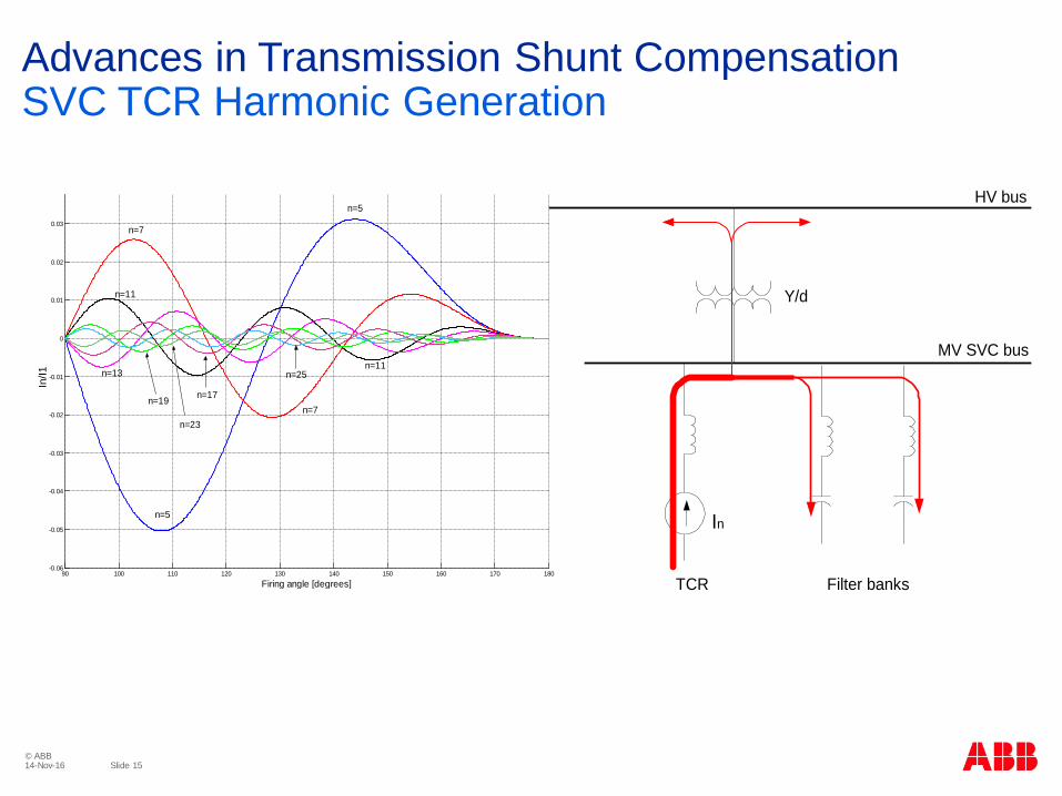
Advances in Transmission Shunt CompensationSVC TCR Harmonic Generation
HV bus
TCR
Y/d
MV SVC bus
In
Filter banks90 100 110 120 130 140 150 160 170 180
-0.06
-0.05
-0.04
-0.03
-0.02
-0.01
0
0.01
0.02
0.03
Firing angle [degrees]
In/I1
n=5
n=5
n=7
n=7
n=11
n=11n=13
n=19 n=17
n=25
n=23

© ABBSlide 1614-Nov-16
Advances in Transmission Shunt CompensationSTATCOM Harmonic Generation
© ABBSlide 1714-Nov-16
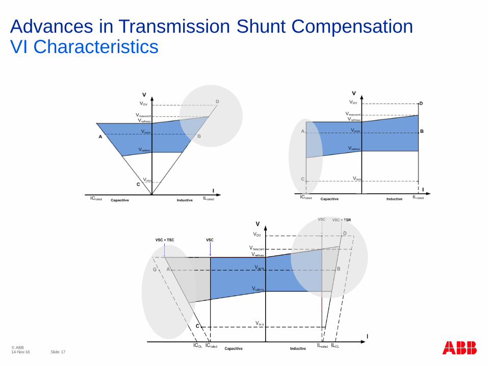
Advances in Transmission Shunt CompensationVI Characteristics