Embed Size (px)
Citation preview
UNIT-IV
SHUNT COMPENSATION
OBJECTIVES OF SHUNT COMPENSATION: Change the natural electrical characteristics of the transmission line to make it morecompatible with the prevailing load demand. Thus, shunt connected, fixed or mechanically switched reactors are applied tominimize line overvoltage under light load conditions, and shunt connected, fixed ormechanically switched capacitors are applied to maintain voltage levels underheavy load conditions. The ultimate objective of applying reactive shunt compensation in a transmissionsystem is to increase the transmittable power
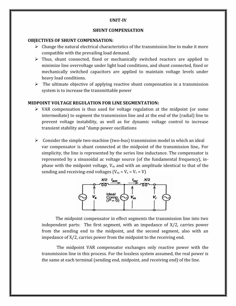
MIDPOINT VOLTAGE REGULATION FOR LINE SEGMENTATION: VAR compensation is thus used for voltage regulation at the midpoint (or someintermediate) to segment the transmission line and at the end of the (radial) line toprevent voltage instability, as well as for dynamic voltage control to increasetransient stability and "damp power oscillations Consider the simple two-machine (two-bus) transmission model in which an idealvar compensator is shunt connected at the midpoint of the transmission line,. Forsimplicity, the line is represented by the series line inductance. The compensator isrepresented by a sinusoidal ac voltage source (of the fundamental frequency), in-phase with the midpoint voltage, Vm and with an amplitude identical to that of thesending and receiving-end voltages (Vm = Vs = Vr = V)
The midpoint compensator in effect segments the transmission line into twoindependent parts: The first segment, with an impedance of X/2, carries powerfrom the sending end to the midpoint, and the second segment, also with animpedance of X/2, carries power from the midpoint to the receiving end.The midpoint VAR compensator exchanges only reactive power with thetransmission line in this process. For the lossless system assumed, the real power isthe same at each terminal (sending end, midpoint, and receiving end) of the line.
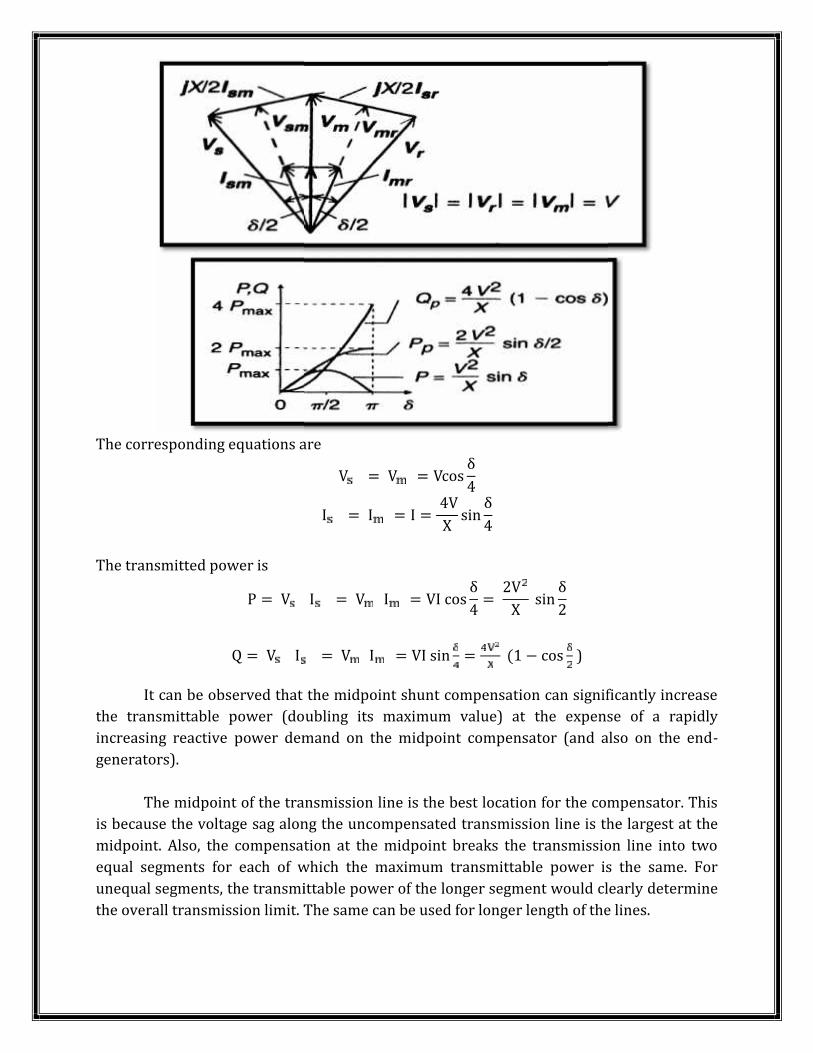
The corresponding equations are V = V = Vcos δ4I = I = I = 4VX sin δ4The transmitted power isP = V I = V I = VI cos δ4 = 2VX sin δ2Q = V I = V I = VI sin = (1 − cos )It can be observed that the midpoint shunt compensation can significantly increasethe transmittable power (doubling its maximum value) at the expense of a rapidlyincreasing reactive power demand on the midpoint compensator (and also on the end-generators).The midpoint of the transmission line is the best location for the compensator. Thisis because the voltage sag along the uncompensated transmission line is the largest at themidpoint. Also, the compensation at the midpoint breaks the transmission line into twoequal segments for each of which the maximum transmittable power is the same. Forunequal segments, the transmittable power of the longer segment would clearly determinethe overall transmission limit. The same can be used for longer length of the lines.
The corresponding equations are V = V = Vcos δ4I = I = I = 4VX sin δ4The transmitted power isP = V I = V I = VI cos δ4 = 2VX sin δ2Q = V I = V I = VI sin = (1 − cos )It can be observed that the midpoint shunt compensation can significantly increasethe transmittable power (doubling its maximum value) at the expense of a rapidlyincreasing reactive power demand on the midpoint compensator (and also on the end-generators).The midpoint of the transmission line is the best location for the compensator. Thisis because the voltage sag along the uncompensated transmission line is the largest at themidpoint. Also, the compensation at the midpoint breaks the transmission line into twoequal segments for each of which the maximum transmittable power is the same. Forunequal segments, the transmittable power of the longer segment would clearly determinethe overall transmission limit. The same can be used for longer length of the lines.
The corresponding equations are V = V = Vcos δ4I = I = I = 4VX sin δ4The transmitted power isP = V I = V I = VI cos δ4 = 2VX sin δ2Q = V I = V I = VI sin = (1 − cos )It can be observed that the midpoint shunt compensation can significantly increasethe transmittable power (doubling its maximum value) at the expense of a rapidlyincreasing reactive power demand on the midpoint compensator (and also on the end-generators).The midpoint of the transmission line is the best location for the compensator. Thisis because the voltage sag along the uncompensated transmission line is the largest at themidpoint. Also, the compensation at the midpoint breaks the transmission line into twoequal segments for each of which the maximum transmittable power is the same. Forunequal segments, the transmittable power of the longer segment would clearly determinethe overall transmission limit. The same can be used for longer length of the lines.
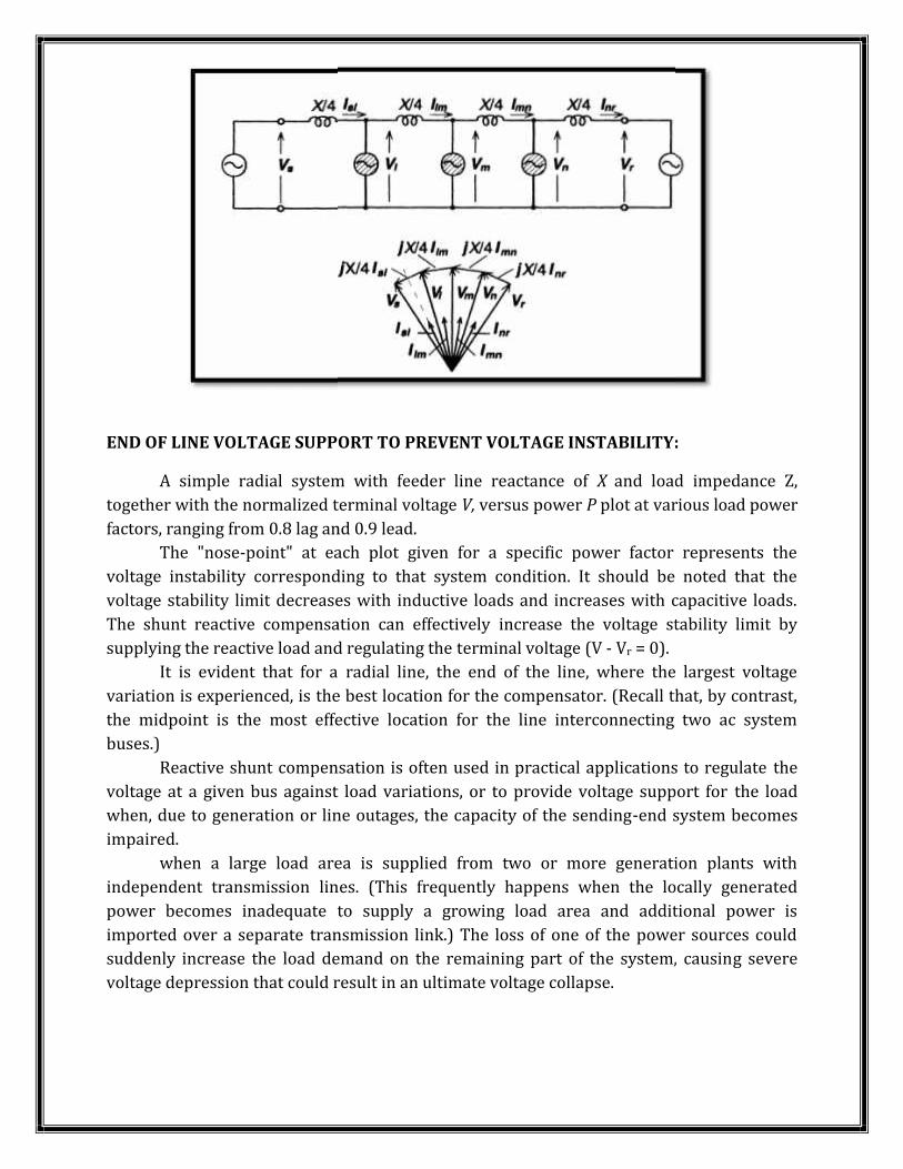
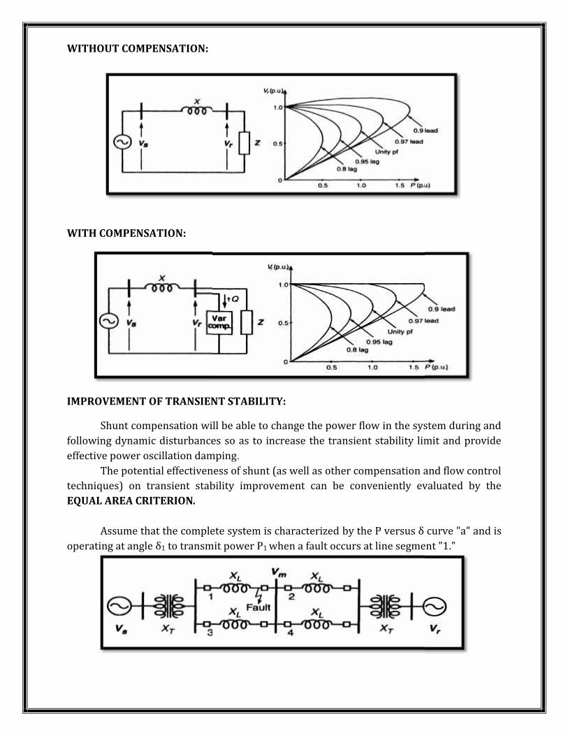
END OF LINE VOLTAGE SUPPORT TO PREVENT VOLTAGE INSTABILITY:A simple radial system with feeder line reactance of X and load impedance Z,together with the normalized terminal voltage V, versus power P plot at various load powerfactors, ranging from 0.8 lag and 0.9 lead.The "nose-point" at each plot given for a specific power factor represents thevoltage instability corresponding to that system condition. It should be noted that thevoltage stability limit decreases with inductive loads and increases with capacitive loads.The shunt reactive compensation can effectively increase the voltage stability limit bysupplying the reactive load and regulating the terminal voltage (V - Vr = 0).It is evident that for a radial line, the end of the line, where the largest voltagevariation is experienced, is the best location for the compensator. (Recall that, by contrast,the midpoint is the most effective location for the line interconnecting two ac systembuses.)Reactive shunt compensation is often used in practical applications to regulate thevoltage at a given bus against load variations, or to provide voltage support for the loadwhen, due to generation or line outages, the capacity of the sending-end system becomesimpaired.when a large load area is supplied from two or more generation plants withindependent transmission lines. (This frequently happens when the locally generatedpower becomes inadequate to supply a growing load area and additional power isimported over a separate transmission link.) The loss of one of the power sources couldsuddenly increase the load demand on the remaining part of the system, causing severevoltage depression that could result in an ultimate voltage collapse.
END OF LINE VOLTAGE SUPPORT TO PREVENT VOLTAGE INSTABILITY:A simple radial system with feeder line reactance of X and load impedance Z,together with the normalized terminal voltage V, versus power P plot at various load powerfactors, ranging from 0.8 lag and 0.9 lead.The "nose-point" at each plot given for a specific power factor represents thevoltage instability corresponding to that system condition. It should be noted that thevoltage stability limit decreases with inductive loads and increases with capacitive loads.The shunt reactive compensation can effectively increase the voltage stability limit bysupplying the reactive load and regulating the terminal voltage (V - Vr = 0).It is evident that for a radial line, the end of the line, where the largest voltagevariation is experienced, is the best location for the compensator. (Recall that, by contrast,the midpoint is the most effective location for the line interconnecting two ac systembuses.)Reactive shunt compensation is often used in practical applications to regulate thevoltage at a given bus against load variations, or to provide voltage support for the loadwhen, due to generation or line outages, the capacity of the sending-end system becomesimpaired.when a large load area is supplied from two or more generation plants withindependent transmission lines. (This frequently happens when the locally generatedpower becomes inadequate to supply a growing load area and additional power isimported over a separate transmission link.) The loss of one of the power sources couldsuddenly increase the load demand on the remaining part of the system, causing severevoltage depression that could result in an ultimate voltage collapse.
END OF LINE VOLTAGE SUPPORT TO PREVENT VOLTAGE INSTABILITY:A simple radial system with feeder line reactance of X and load impedance Z,together with the normalized terminal voltage V, versus power P plot at various load powerfactors, ranging from 0.8 lag and 0.9 lead.The "nose-point" at each plot given for a specific power factor represents thevoltage instability corresponding to that system condition. It should be noted that thevoltage stability limit decreases with inductive loads and increases with capacitive loads.The shunt reactive compensation can effectively increase the voltage stability limit bysupplying the reactive load and regulating the terminal voltage (V - Vr = 0).It is evident that for a radial line, the end of the line, where the largest voltagevariation is experienced, is the best location for the compensator. (Recall that, by contrast,the midpoint is the most effective location for the line interconnecting two ac systembuses.)Reactive shunt compensation is often used in practical applications to regulate thevoltage at a given bus against load variations, or to provide voltage support for the loadwhen, due to generation or line outages, the capacity of the sending-end system becomesimpaired.when a large load area is supplied from two or more generation plants withindependent transmission lines. (This frequently happens when the locally generatedpower becomes inadequate to supply a growing load area and additional power isimported over a separate transmission link.) The loss of one of the power sources couldsuddenly increase the load demand on the remaining part of the system, causing severevoltage depression that could result in an ultimate voltage collapse.
WITHOUT COMPENSATION:
WITH COMPENSATION:
IMPROVEMENT OF TRANSIENT STABILITY:Shunt compensation will be able to change the power flow in the system during andfollowing dynamic disturbances so as to increase the transient stability limit and provideeffective power oscillation damping.The potential effectiveness of shunt (as well as other compensation and flow controltechniques) on transient stability improvement can be conveniently evaluated by theEQUAL AREA CRITERION.Assume that the complete system is characterized by the P versus δ curve "a" and isoperating at angle δ1 to transmit power P1 when a fault occurs at line segment "1."
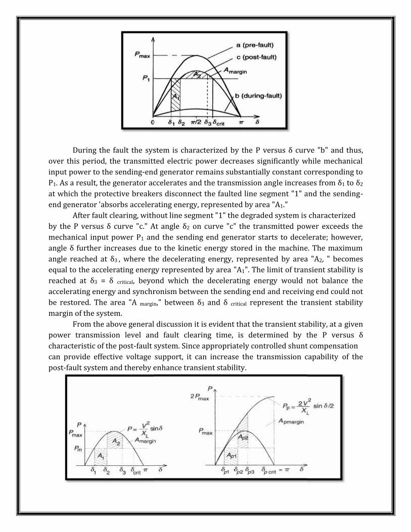
During the fault the system is characterized by the P versus δ curve "b" and thus,over this period, the transmitted electric power decreases significantly while mechanicalinput power to the sending-end generator remains substantially constant corresponding toP1. As a result, the generator accelerates and the transmission angle increases from δ1 to δ2at which the protective breakers disconnect the faulted line segment "1" and the sending-end generator 'absorbs accelerating energy, represented by area "A1."After fault clearing, without line segment "1" the degraded system is characterizedby the P versus δ curve "c." At angle δ2 on curve "c" the transmitted power exceeds themechanical input power P1 and the sending end generator starts to decelerate; however,angle δ further increases due to the kinetic energy stored in the machine. The maximumangle reached at δ3 , where the decelerating energy, represented by area "A2, " becomesequal to the accelerating energy represented by area "A1". The limit of transient stability isreached at δ3 = δ critical, beyond which the decelerating energy would not balance theaccelerating energy and synchronism between the sending end and receiving end could notbe restored. The area "A margin," between δ3 and δ critical represent the transient stabilitymargin of the system.From the above general discussion it is evident that the transient stability, at a givenpower transmission level and fault clearing time, is determined by the P versus δcharacteristic of the post-fault system. Since appropriately controlled shunt compensationcan provide effective voltage support, it can increase the transmission capability of thepost-fault system and thereby enhance transient stability.
During the fault the system is characterized by the P versus δ curve "b" and thus,over this period, the transmitted electric power decreases significantly while mechanicalinput power to the sending-end generator remains substantially constant corresponding toP1. As a result, the generator accelerates and the transmission angle increases from δ1 to δ2at which the protective breakers disconnect the faulted line segment "1" and the sending-end generator 'absorbs accelerating energy, represented by area "A1."After fault clearing, without line segment "1" the degraded system is characterizedby the P versus δ curve "c." At angle δ2 on curve "c" the transmitted power exceeds themechanical input power P1 and the sending end generator starts to decelerate; however,angle δ further increases due to the kinetic energy stored in the machine. The maximumangle reached at δ3 , where the decelerating energy, represented by area "A2, " becomesequal to the accelerating energy represented by area "A1". The limit of transient stability isreached at δ3 = δ critical, beyond which the decelerating energy would not balance theaccelerating energy and synchronism between the sending end and receiving end could notbe restored. The area "A margin," between δ3 and δ critical represent the transient stabilitymargin of the system.From the above general discussion it is evident that the transient stability, at a givenpower transmission level and fault clearing time, is determined by the P versus δcharacteristic of the post-fault system. Since appropriately controlled shunt compensationcan provide effective voltage support, it can increase the transmission capability of thepost-fault system and thereby enhance transient stability.
During the fault the system is characterized by the P versus δ curve "b" and thus,over this period, the transmitted electric power decreases significantly while mechanicalinput power to the sending-end generator remains substantially constant corresponding toP1. As a result, the generator accelerates and the transmission angle increases from δ1 to δ2at which the protective breakers disconnect the faulted line segment "1" and the sending-end generator 'absorbs accelerating energy, represented by area "A1."After fault clearing, without line segment "1" the degraded system is characterizedby the P versus δ curve "c." At angle δ2 on curve "c" the transmitted power exceeds themechanical input power P1 and the sending end generator starts to decelerate; however,angle δ further increases due to the kinetic energy stored in the machine. The maximumangle reached at δ3 , where the decelerating energy, represented by area "A2, " becomesequal to the accelerating energy represented by area "A1". The limit of transient stability isreached at δ3 = δ critical, beyond which the decelerating energy would not balance theaccelerating energy and synchronism between the sending end and receiving end could notbe restored. The area "A margin," between δ3 and δ critical represent the transient stabilitymargin of the system.From the above general discussion it is evident that the transient stability, at a givenpower transmission level and fault clearing time, is determined by the P versus δcharacteristic of the post-fault system. Since appropriately controlled shunt compensationcan provide effective voltage support, it can increase the transmission capability of thepost-fault system and thereby enhance transient stability.
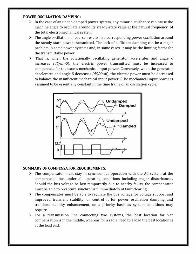
POWER OSCILLATION DAMPING: In the case of an under-damped power system, any minor disturbance can cause themachine angle to oscillate around its steady-state value at the natural frequency ofthe total electromechanical system. The angle oscillation, of course, results in a corresponding power oscillation aroundthe steady-state power transmitted. The lack of sufficient damping can be a majorproblem in some power systems and, in some cases, it may be the limiting factor forthe transmittable power. That is, when the rotationally oscillating generator accelerates and angle δincreases (dδ/dt>0), the electric power transmitted must be increased tocompensate for the excess mechanical input power. Conversely, when the generatordecelerates and angle δ decreases (dδ/dt<0), the electric power must be decreasedto balance the insufficient mechanical input power. (The mechanical input power isassumed to be essentially constant in the time frame of an oscillation cycle.)
SUMMARY OF COMPENSATOR REQUIREMENTS: The compensator must stay in synchronous operation with the AC system at thecompensated bus under all operating conditions including major disturbances.Should the bus voltage be lost temporarily due to nearby faults, the compensatormust be able to recapture synchronism immediately at fault clearing. The compensator must be able to regulate the bus voltage for voltage support andimproved transient stability, or control it for power oscillation damping andtransient stability enhancement, on a priority basis as system conditions mayrequire. For a transmission line connecting two systems, the best location for Varcompensation is in the middle, whereas for a radial feed to a load the best location isat the load end.
METHODS OF CONTROLLABLE VAR GENERATION:
VARIABLE IMPEDANCE TYPE STATIC VAR GENERATORS:o THYRISTOR CONTROLLED/ SWITCHED REACTOR (TCR/TSR)o THYRISTOR SWITCHED CAPACITOR (TSC)o FIXED CAPACITOR- THYRISTOR CONTROLLED REACTOR (FC-TCR).o THYRISTOR SWITCHED CAPACITOR-THYRISTOR CONTROLLED REACTOR
SWITCHING CONVERTER TYPE VAR GENERATORS:o STATIC CONDENSOR & STATIC COMPENSTOR (STATCON & STATCOM)
HYBRID VAR GENERATORS:o SWITCHING CONVERTER WITH TSC AND TCR
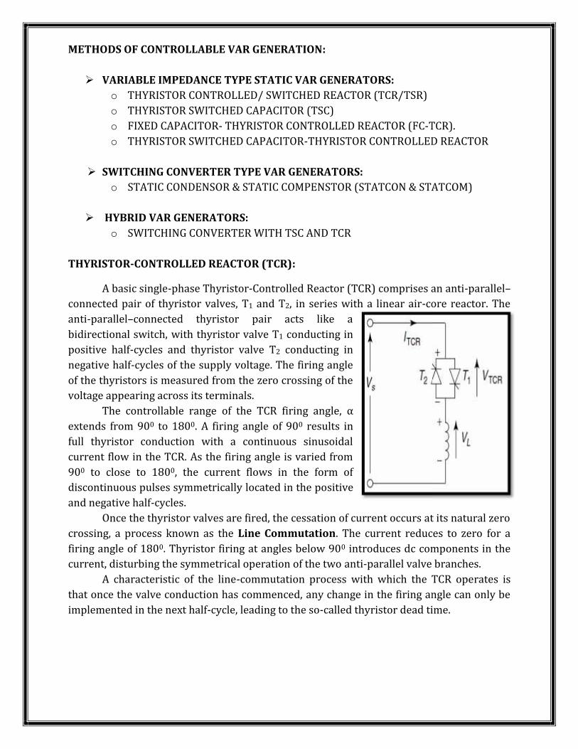
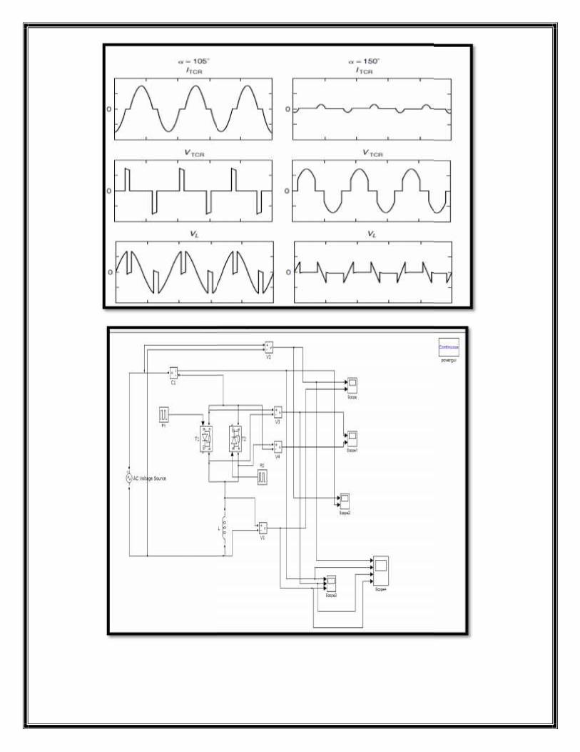
THYRISTOR-CONTROLLED REACTOR (TCR):A basic single-phase Thyristor-Controlled Reactor (TCR) comprises an anti-parallel–connected pair of thyristor valves, T1 and T2, in series with a linear air-core reactor. Theanti-parallel–connected thyristor pair acts like abidirectional switch, with thyristor valve T1 conducting inpositive half-cycles and thyristor valve T2 conducting innegative half-cycles of the supply voltage. The firing angleof the thyristors is measured from the zero crossing of thevoltage appearing across its terminals.The controllable range of the TCR firing angle, αextends from 900 to 1800. A firing angle of 900 results infull thyristor conduction with a continuous sinusoidalcurrent flow in the TCR. As the firing angle is varied from900 to close to 1800, the current flows in the form ofdiscontinuous pulses symmetrically located in the positiveand negative half-cycles.Once the thyristor valves are fired, the cessation of current occurs at its natural zerocrossing, a process known as the Line Commutation. The current reduces to zero for afiring angle of 1800. Thyristor firing at angles below 900 introduces dc components in thecurrent, disturbing the symmetrical operation of the two anti-parallel valve branches.A characteristic of the line-commutation process with which the TCR operates isthat once the valve conduction has commenced, any change in the firing angle can only beimplemented in the next half-cycle, leading to the so-called thyristor dead time.
METHODS OF CONTROLLABLE VAR GENERATION:
VARIABLE IMPEDANCE TYPE STATIC VAR GENERATORS:o THYRISTOR CONTROLLED/ SWITCHED REACTOR (TCR/TSR)o THYRISTOR SWITCHED CAPACITOR (TSC)o FIXED CAPACITOR- THYRISTOR CONTROLLED REACTOR (FC-TCR).o THYRISTOR SWITCHED CAPACITOR-THYRISTOR CONTROLLED REACTOR
SWITCHING CONVERTER TYPE VAR GENERATORS:o STATIC CONDENSOR & STATIC COMPENSTOR (STATCON & STATCOM)
HYBRID VAR GENERATORS:o SWITCHING CONVERTER WITH TSC AND TCR
THYRISTOR-CONTROLLED REACTOR (TCR):A basic single-phase Thyristor-Controlled Reactor (TCR) comprises an anti-parallel–connected pair of thyristor valves, T1 and T2, in series with a linear air-core reactor. Theanti-parallel–connected thyristor pair acts like abidirectional switch, with thyristor valve T1 conducting inpositive half-cycles and thyristor valve T2 conducting innegative half-cycles of the supply voltage. The firing angleof the thyristors is measured from the zero crossing of thevoltage appearing across its terminals.The controllable range of the TCR firing angle, αextends from 900 to 1800. A firing angle of 900 results infull thyristor conduction with a continuous sinusoidalcurrent flow in the TCR. As the firing angle is varied from900 to close to 1800, the current flows in the form ofdiscontinuous pulses symmetrically located in the positiveand negative half-cycles.Once the thyristor valves are fired, the cessation of current occurs at its natural zerocrossing, a process known as the Line Commutation. The current reduces to zero for afiring angle of 1800. Thyristor firing at angles below 900 introduces dc components in thecurrent, disturbing the symmetrical operation of the two anti-parallel valve branches.A characteristic of the line-commutation process with which the TCR operates isthat once the valve conduction has commenced, any change in the firing angle can only beimplemented in the next half-cycle, leading to the so-called thyristor dead time.
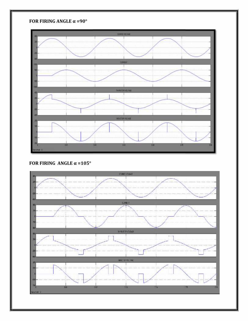
FOR FIRING ANGLE α =90°
FOR FIRING ANGLE α =105°
FOR FIRING ANGLE α =90°
FOR FIRING ANGLE α =105°
FOR FIRING ANGLE α =90°
FOR FIRING ANGLE α =105°
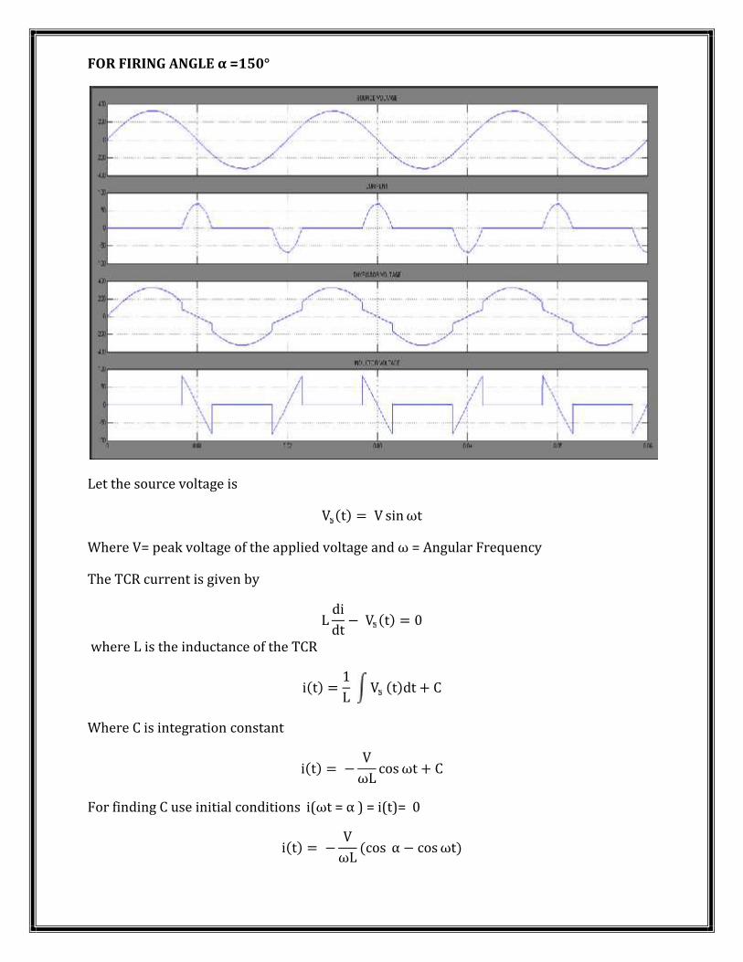
FOR FIRING ANGLE α =150°
Let the source voltage is V (t) = V sinωtWhere V= peak voltage of the applied voltage and ω = Angular FrequencyThe TCR current is given byL didt − V (t) = 0where L is the inductance of the TCR
i(t) = 1L V (t)dt + CWhere C is integration constanti(t) = − VωL cosωt + CFor finding C use initial conditions i(ωt = α ) = i(t)= 0
i(t) = − VωL (cos α − cosωt)
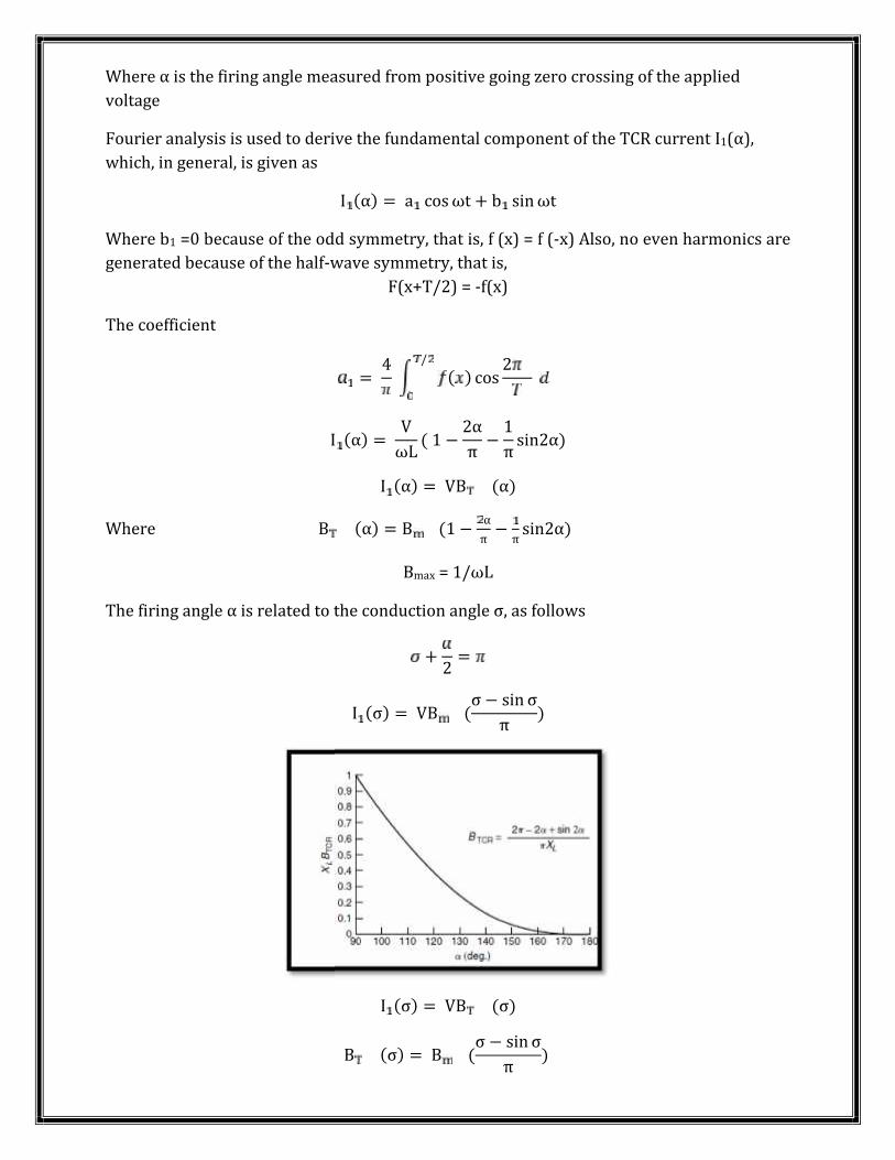
Where α is the firing angle measured from positive going zero crossing of the appliedvoltageFourier analysis is used to derive the fundamental component of the TCR current I1(α),which, in general, is given as I (α) = a cosωt + b sinωtWhere b1 =0 because of the odd symmetry, that is, f (x) = f (-x) Also, no even harmonics aregenerated because of the half-wave symmetry, that is,F(x+T/2) = -f(x)The coefficient= 4 ( ) cos 2/
I (α) = VωL ( 1 − 2απ − 1π sin2α)I (α) = VB (α)Where B (α) = B (1 − απ − π sin2α)Bmax = 1/ωLThe firing angle α is related to the conduction angle σ, as follows+ 2 =I (σ) = VB (σ − sin σπ )
I (σ) = VB (σ)B (σ) = B (σ − sin σπ )
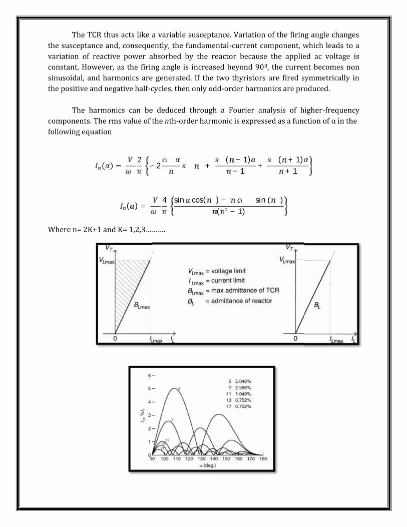
The TCR thus acts like a variable susceptance. Variation of the firing angle changesthe susceptance and, consequently, the fundamental-current component, which leads to avariation of reactive power absorbed by the reactor because the applied ac voltage isconstant. However, as the firing angle is increased beyond 900, the current becomes nonsinusoidal, and harmonics are generated. If the two thyristors are fired symmetrically inthe positive and negative half-cycles, then only odd-order harmonics are produced.The harmonics can be deduced through a Fourier analysis of higher-frequencycomponents. The rms value of the nth-order harmonic is expressed as a function of α in thefollowing equation( ) = 2 −2 + ( − 1)− 1 + ( + 1)+ 1
( ) = 4 sin cos( ) − sin ( )( − 1)Where n= 2K+1 and K= 1,2,3……….
The TCR thus acts like a variable susceptance. Variation of the firing angle changesthe susceptance and, consequently, the fundamental-current component, which leads to avariation of reactive power absorbed by the reactor because the applied ac voltage isconstant. However, as the firing angle is increased beyond 900, the current becomes nonsinusoidal, and harmonics are generated. If the two thyristors are fired symmetrically inthe positive and negative half-cycles, then only odd-order harmonics are produced.The harmonics can be deduced through a Fourier analysis of higher-frequencycomponents. The rms value of the nth-order harmonic is expressed as a function of α in thefollowing equation( ) = 2 − 2 + ( − 1)− 1 + ( + 1)+ 1
( ) = 4 sin cos( ) − sin ( )( − 1)Where n= 2K+1 and K= 1,2,3……….
THYRISTOR-SWITCHED REACTOR:
The TSR is a special case of a TCR in which the variable firing-angle control option isnot exercised. Instead, the device is operated in two states only: either fully on orfully off. If the thyristor valves are fired exactly at the voltage peaks corresponding to α = 90°for the forward-thyristor valve T1 and α = 270° (90 + 180) for the reverse-thyristorvalve T2, The maximum inductive current flows in the TCR as if the thyristorswitches were replaced by short circuits. However, if no firing pulses are issued tothe thyristors, the TSR will remain in a blocked-off state, and no current can flow. The TSR ensures a very rapid availability of rated inductive reactive power to thesystem. When a large magnitude of controlled reactive power, Q, is required, a partof Q is usually assigned to a small TSR of rating, say, Q/2; the rest is realized bymeans of a TCR also of a reduced rating Q/2. This arrangement results insubstantially decreased losses and harmonic content as compared to a single TCR ofrating Q.
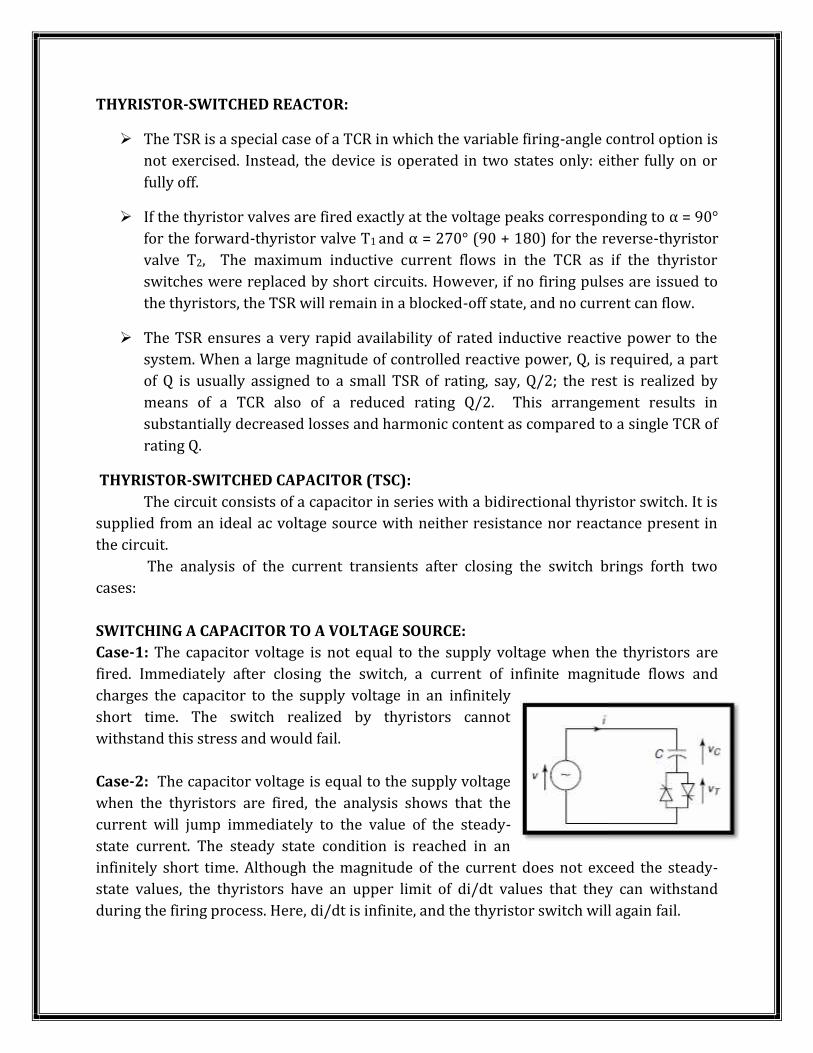
THYRISTOR-SWITCHED CAPACITOR (TSC):The circuit consists of a capacitor in series with a bidirectional thyristor switch. It issupplied from an ideal ac voltage source with neither resistance nor reactance present inthe circuit.The analysis of the current transients after closing the switch brings forth twocases:SWITCHING A CAPACITOR TO A VOLTAGE SOURCE:Case-1: The capacitor voltage is not equal to the supply voltage when the thyristors arefired. Immediately after closing the switch, a current of infinite magnitude flows andcharges the capacitor to the supply voltage in an infinitelyshort time. The switch realized by thyristors cannotwithstand this stress and would fail.Case-2: The capacitor voltage is equal to the supply voltagewhen the thyristors are fired, the analysis shows that thecurrent will jump immediately to the value of the steady-state current. The steady state condition is reached in aninfinitely short time. Although the magnitude of the current does not exceed the steady-state values, the thyristors have an upper limit of di/dt values that they can withstandduring the firing process. Here, di/dt is infinite, and the thyristor switch will again fail.
THYRISTOR-SWITCHED REACTOR:
The TSR is a special case of a TCR in which the variable firing-angle control option isnot exercised. Instead, the device is operated in two states only: either fully on orfully off. If the thyristor valves are fired exactly at the voltage peaks corresponding to α = 90°for the forward-thyristor valve T1 and α = 270° (90 + 180) for the reverse-thyristorvalve T2, The maximum inductive current flows in the TCR as if the thyristorswitches were replaced by short circuits. However, if no firing pulses are issued tothe thyristors, the TSR will remain in a blocked-off state, and no current can flow. The TSR ensures a very rapid availability of rated inductive reactive power to thesystem. When a large magnitude of controlled reactive power, Q, is required, a partof Q is usually assigned to a small TSR of rating, say, Q/2; the rest is realized bymeans of a TCR also of a reduced rating Q/2. This arrangement results insubstantially decreased losses and harmonic content as compared to a single TCR ofrating Q.
THYRISTOR-SWITCHED CAPACITOR (TSC):The circuit consists of a capacitor in series with a bidirectional thyristor switch. It issupplied from an ideal ac voltage source with neither resistance nor reactance present inthe circuit.The analysis of the current transients after closing the switch brings forth twocases:SWITCHING A CAPACITOR TO A VOLTAGE SOURCE:Case-1: The capacitor voltage is not equal to the supply voltage when the thyristors arefired. Immediately after closing the switch, a current of infinite magnitude flows andcharges the capacitor to the supply voltage in an infinitelyshort time. The switch realized by thyristors cannotwithstand this stress and would fail.Case-2: The capacitor voltage is equal to the supply voltagewhen the thyristors are fired, the analysis shows that thecurrent will jump immediately to the value of the steady-state current. The steady state condition is reached in aninfinitely short time. Although the magnitude of the current does not exceed the steady-state values, the thyristors have an upper limit of di/dt values that they can withstandduring the firing process. Here, di/dt is infinite, and the thyristor switch will again fail.
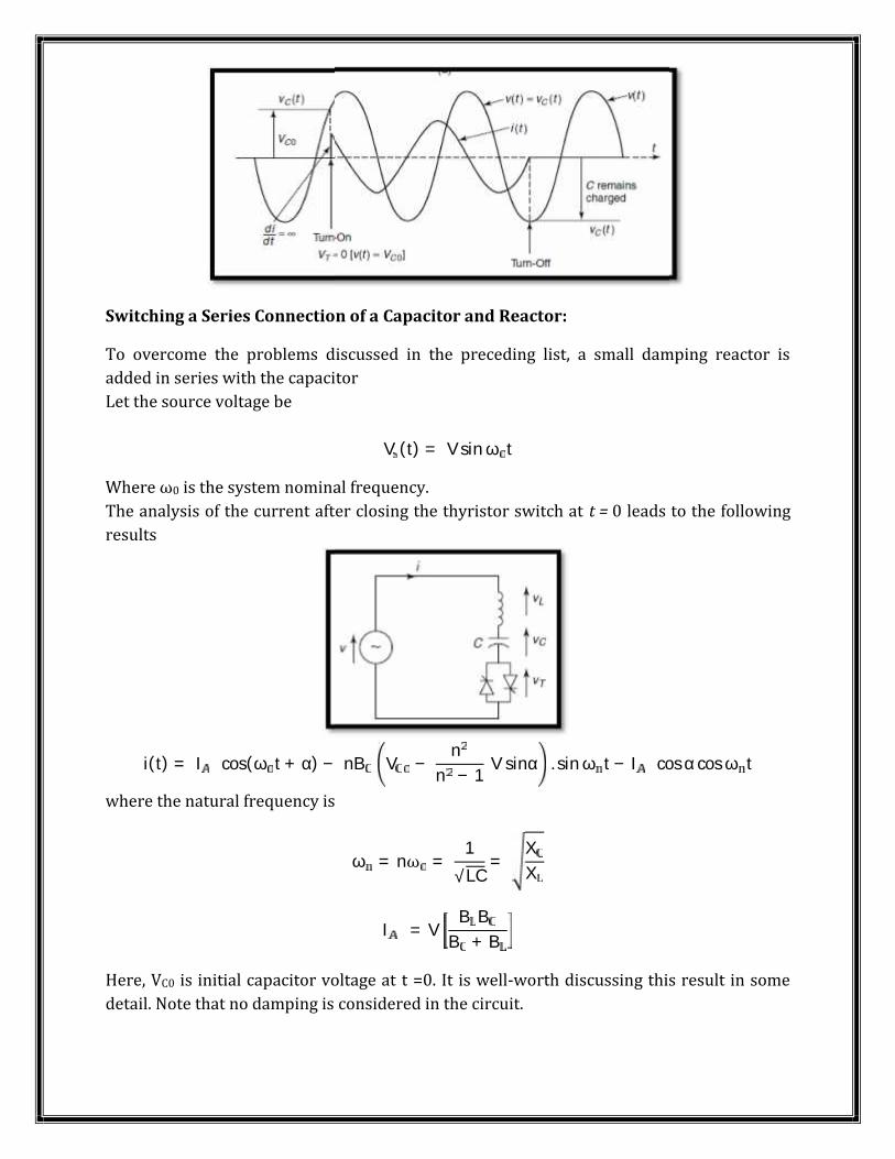
Switching a Series Connection of a Capacitor and Reactor:To overcome the problems discussed in the preceding list, a small damping reactor isadded in series with the capacitorLet the source voltage be V (t) = V sin ω tWhere ω0 is the system nominal frequency.The analysis of the current after closing the thyristor switch at t = 0 leads to the followingresults
i(t) = I cos(ω t + α) − nB V − nn − 1 V sinα . sin ω t − I cos α cos ω twhere the natural frequency isω = nω = 1√LC = XX
I = V B BB + BHere, VC0 is initial capacitor voltage at t =0. It is well-worth discussing this result in somedetail. Note that no damping is considered in the circuit.
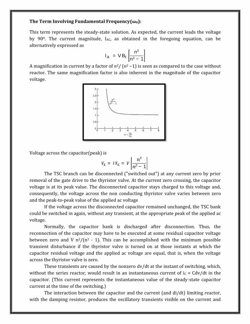
The Term Involving Fundamental Frequency(ω0):This term represents the steady-state solution. As expected, the current leads the voltageby 900. The current magnitude, IAC, as obtained in the foregoing equation, can bealternatively expressed as I = V B nn − 1A magnification in current by a factor of n2/ (n2 −1) is seen as compared to the case withoutreactor. The same magnification factor is also inherent in the magnitude of the capacitorvoltage.
Voltage across the capacitor(peak) is = = − 1The TSC branch can be disconnected ("switched out") at any current zero by priorremoval of the gate drive to the thyristor valve. At the current zero crossing, the capacitorvoltage is at its peak value. The disconnected capacitor stays charged to this voltage and,consequently, the voltage across the non conducting thyristor valve varies between zeroand the peak-to-peak value of the applied ac voltageIf the voltage across the disconnected capacitor remained unchanged, the TSC bankcould be switched in again, without any transient, at the appropriate peak of the applied acvoltage.Normally, the capacitor bank is discharged after disconnection. Thus, thereconnection of the capacitor may have to be executed at some residual capacitor voltagebetween zero and V n2/(n2 - 1). This can be accomplished with the minimum possibletransient disturbance if the thyristor valve is turned on at those instants at which thecapacitor residual voltage and the applied ac voltage are equal, that is, when the voltageacross the thyristor valve is zero.These transients are caused by the nonzero dv/dt at the instant of switching, which,without the series reactor, would result in an instantaneous current of iC = Cdv/dt in thecapacitor. (This current represents the instantaneous value of the steady-state capacitorcurrent at the time of the switching.)The interaction between the capacitor and the current (and di/dt) limiting reactor,with the damping resistor, produces the oscillatory transients visible on the current and
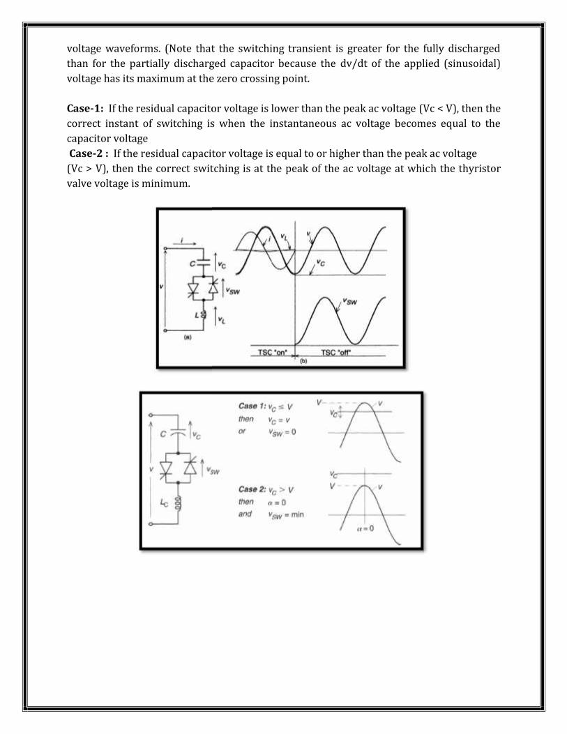
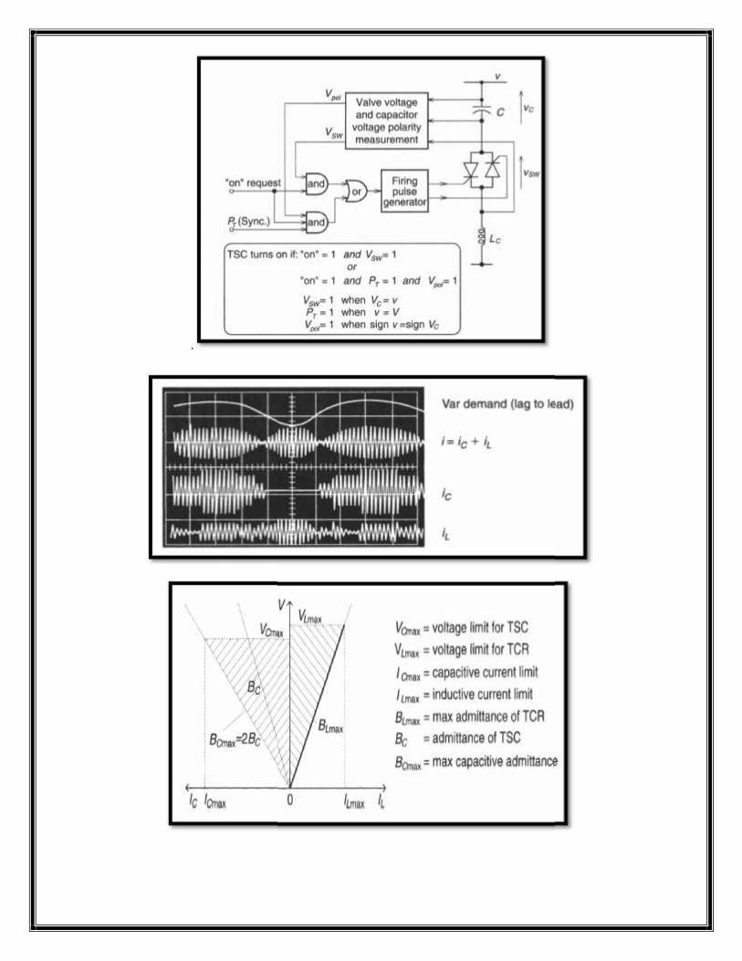
voltage waveforms. (Note that the switching transient is greater for the fully dischargedthan for the partially discharged capacitor because the dv/dt of the applied (sinusoidal)voltage has its maximum at the zero crossing point.Case-1: If the residual capacitor voltage is lower than the peak ac voltage (Vc < V), then thecorrect instant of switching is when the instantaneous ac voltage becomes equal to thecapacitor voltageCase-2 : If the residual capacitor voltage is equal to or higher than the peak ac voltage(Vc > V), then the correct switching is at the peak of the ac voltage at which the thyristorvalve voltage is minimum.
voltage waveforms. (Note that the switching transient is greater for the fully dischargedthan for the partially discharged capacitor because the dv/dt of the applied (sinusoidal)voltage has its maximum at the zero crossing point.Case-1: If the residual capacitor voltage is lower than the peak ac voltage (Vc < V), then thecorrect instant of switching is when the instantaneous ac voltage becomes equal to thecapacitor voltageCase-2 : If the residual capacitor voltage is equal to or higher than the peak ac voltage(Vc > V), then the correct switching is at the peak of the ac voltage at which the thyristorvalve voltage is minimum.
voltage waveforms. (Note that the switching transient is greater for the fully dischargedthan for the partially discharged capacitor because the dv/dt of the applied (sinusoidal)voltage has its maximum at the zero crossing point.Case-1: If the residual capacitor voltage is lower than the peak ac voltage (Vc < V), then thecorrect instant of switching is when the instantaneous ac voltage becomes equal to thecapacitor voltageCase-2 : If the residual capacitor voltage is equal to or higher than the peak ac voltage(Vc > V), then the correct switching is at the peak of the ac voltage at which the thyristorvalve voltage is minimum.
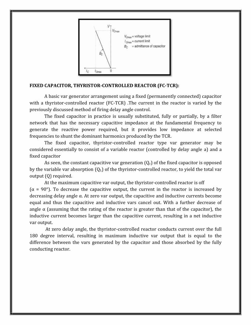
FIXED CAPACITOR, THYRISTOR-CONTROLLED REACTOR (FC-TCR):A basic var generator arrangement using a fixed (permanently connected) capacitorwith a thyristor-controlled reactor (FC-TCR) .The current in the reactor is varied by thepreviously discussed method of firing delay angle control.The fixed capacitor in practice is usually substituted, fully or partially, by a filternetwork that has the necessary capacitive impedance at the fundamental frequency togenerate the reactive power required, but it provides low impedance at selectedfrequencies to shunt the dominant harmonics produced by the TCR.The fixed capacitor, thyristor-controlled reactor type var generator may beconsidered essentially to consist of a variable reactor (controlled by delay angle a) and afixed capacitorAs seen, the constant capacitive var generation (Qc) of the fixed capacitor is opposedby the variable var absorption (QL) of the thyristor-controlled reactor, to yield the total varoutput (Q) required.At the maximum capacitive var output, the thyristor-controlled reactor is off(α = 90°). To decrease the capacitive output, the current in the reactor is increased bydecreasing delay angle α. At zero var output, the capacitive and inductive currents becomeequal and thus the capacitive and inductive vars cancel out. With a further decrease ofangle α (assuming that the rating of the reactor is greater than that of the capacitor), theinductive current becomes larger than the capacitive current, resulting in a net inductivevar output.At zero delay angle, the thyristor-controlled reactor conducts current over the full180 degree interval, resulting in maximum inductive var output that is equal to thedifference between the vars generated by the capacitor and those absorbed by the fullyconducting reactor.
FIXED CAPACITOR, THYRISTOR-CONTROLLED REACTOR (FC-TCR):A basic var generator arrangement using a fixed (permanently connected) capacitorwith a thyristor-controlled reactor (FC-TCR) .The current in the reactor is varied by thepreviously discussed method of firing delay angle control.The fixed capacitor in practice is usually substituted, fully or partially, by a filternetwork that has the necessary capacitive impedance at the fundamental frequency togenerate the reactive power required, but it provides low impedance at selectedfrequencies to shunt the dominant harmonics produced by the TCR.The fixed capacitor, thyristor-controlled reactor type var generator may beconsidered essentially to consist of a variable reactor (controlled by delay angle a) and afixed capacitorAs seen, the constant capacitive var generation (Qc) of the fixed capacitor is opposedby the variable var absorption (QL) of the thyristor-controlled reactor, to yield the total varoutput (Q) required.At the maximum capacitive var output, the thyristor-controlled reactor is off(α = 90°). To decrease the capacitive output, the current in the reactor is increased bydecreasing delay angle α. At zero var output, the capacitive and inductive currents becomeequal and thus the capacitive and inductive vars cancel out. With a further decrease ofangle α (assuming that the rating of the reactor is greater than that of the capacitor), theinductive current becomes larger than the capacitive current, resulting in a net inductivevar output.At zero delay angle, the thyristor-controlled reactor conducts current over the full180 degree interval, resulting in maximum inductive var output that is equal to thedifference between the vars generated by the capacitor and those absorbed by the fullyconducting reactor.
FIXED CAPACITOR, THYRISTOR-CONTROLLED REACTOR (FC-TCR):A basic var generator arrangement using a fixed (permanently connected) capacitorwith a thyristor-controlled reactor (FC-TCR) .The current in the reactor is varied by thepreviously discussed method of firing delay angle control.The fixed capacitor in practice is usually substituted, fully or partially, by a filternetwork that has the necessary capacitive impedance at the fundamental frequency togenerate the reactive power required, but it provides low impedance at selectedfrequencies to shunt the dominant harmonics produced by the TCR.The fixed capacitor, thyristor-controlled reactor type var generator may beconsidered essentially to consist of a variable reactor (controlled by delay angle a) and afixed capacitorAs seen, the constant capacitive var generation (Qc) of the fixed capacitor is opposedby the variable var absorption (QL) of the thyristor-controlled reactor, to yield the total varoutput (Q) required.At the maximum capacitive var output, the thyristor-controlled reactor is off(α = 90°). To decrease the capacitive output, the current in the reactor is increased bydecreasing delay angle α. At zero var output, the capacitive and inductive currents becomeequal and thus the capacitive and inductive vars cancel out. With a further decrease ofangle α (assuming that the rating of the reactor is greater than that of the capacitor), theinductive current becomes larger than the capacitive current, resulting in a net inductivevar output.At zero delay angle, the thyristor-controlled reactor conducts current over the full180 degree interval, resulting in maximum inductive var output that is equal to thedifference between the vars generated by the capacitor and those absorbed by the fullyconducting reactor.
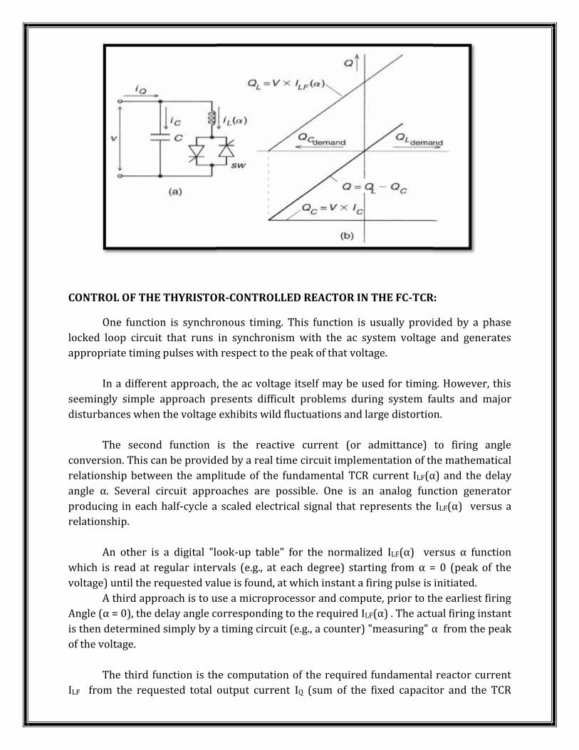
CONTROL OF THE THYRISTOR-CONTROLLED REACTOR IN THE FC-TCR:One function is synchronous timing. This function is usually provided by a phaselocked loop circuit that runs in synchronism with the ac system voltage and generatesappropriate timing pulses with respect to the peak of that voltage.In a different approach, the ac voltage itself may be used for timing. However, thisseemingly simple approach presents difficult problems during system faults and majordisturbances when the voltage exhibits wild fluctuations and large distortion.The second function is the reactive current (or admittance) to firing angleconversion. This can be provided by a real time circuit implementation of the mathematicalrelationship between the amplitude of the fundamental TCR current ILF(α) and the delayangle α. Several circuit approaches are possible. One is an analog function generatorproducing in each half-cycle a scaled electrical signal that represents the ILF(α) versus arelationship.An other is a digital "look-up table" for the normalized ILF(α) versus α functionwhich is read at regular intervals (e.g., at each degree) starting from α = 0 (peak of thevoltage) until the requested value is found, at which instant a firing pulse is initiated.A third approach is to use a microprocessor and compute, prior to the earliest firingAngle (α = 0), the delay angle corresponding to the required ILF(α) . The actual firing instantis then determined simply by a timing circuit (e.g., a counter) "measuring" α from the peakof the voltage.The third function is the computation of the required fundamental reactor currentILF from the requested total output current IQ (sum of the fixed capacitor and the TCR
CONTROL OF THE THYRISTOR-CONTROLLED REACTOR IN THE FC-TCR:One function is synchronous timing. This function is usually provided by a phaselocked loop circuit that runs in synchronism with the ac system voltage and generatesappropriate timing pulses with respect to the peak of that voltage.In a different approach, the ac voltage itself may be used for timing. However, thisseemingly simple approach presents difficult problems during system faults and majordisturbances when the voltage exhibits wild fluctuations and large distortion.The second function is the reactive current (or admittance) to firing angleconversion. This can be provided by a real time circuit implementation of the mathematicalrelationship between the amplitude of the fundamental TCR current ILF(α) and the delayangle α. Several circuit approaches are possible. One is an analog function generatorproducing in each half-cycle a scaled electrical signal that represents the ILF(α) versus arelationship.An other is a digital "look-up table" for the normalized ILF(α) versus α functionwhich is read at regular intervals (e.g., at each degree) starting from α = 0 (peak of thevoltage) until the requested value is found, at which instant a firing pulse is initiated.A third approach is to use a microprocessor and compute, prior to the earliest firingAngle (α = 0), the delay angle corresponding to the required ILF(α) . The actual firing instantis then determined simply by a timing circuit (e.g., a counter) "measuring" α from the peakof the voltage.The third function is the computation of the required fundamental reactor currentILF from the requested total output current IQ (sum of the fixed capacitor and the TCR
CONTROL OF THE THYRISTOR-CONTROLLED REACTOR IN THE FC-TCR:One function is synchronous timing. This function is usually provided by a phaselocked loop circuit that runs in synchronism with the ac system voltage and generatesappropriate timing pulses with respect to the peak of that voltage.In a different approach, the ac voltage itself may be used for timing. However, thisseemingly simple approach presents difficult problems during system faults and majordisturbances when the voltage exhibits wild fluctuations and large distortion.The second function is the reactive current (or admittance) to firing angleconversion. This can be provided by a real time circuit implementation of the mathematicalrelationship between the amplitude of the fundamental TCR current ILF(α) and the delayangle α. Several circuit approaches are possible. One is an analog function generatorproducing in each half-cycle a scaled electrical signal that represents the ILF(α) versus arelationship.An other is a digital "look-up table" for the normalized ILF(α) versus α functionwhich is read at regular intervals (e.g., at each degree) starting from α = 0 (peak of thevoltage) until the requested value is found, at which instant a firing pulse is initiated.A third approach is to use a microprocessor and compute, prior to the earliest firingAngle (α = 0), the delay angle corresponding to the required ILF(α) . The actual firing instantis then determined simply by a timing circuit (e.g., a counter) "measuring" α from the peakof the voltage.The third function is the computation of the required fundamental reactor currentILF from the requested total output current IQ (sum of the fixed capacitor and the TCR
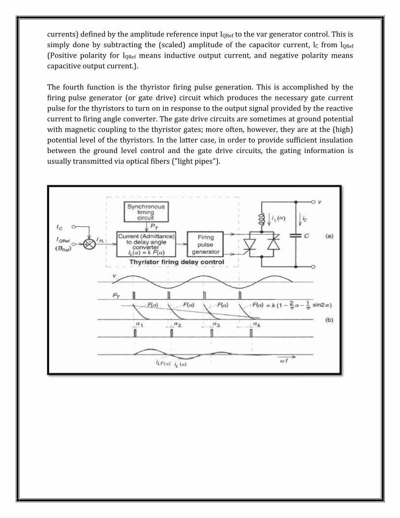
currents) defined by the amplitude reference input IQRef to the var generator control. This issimply done by subtracting the (scaled) amplitude of the capacitor current, lC from lQRef(Positive polarity for lQRef means inductive output current, and negative polarity meanscapacitive output current.).The fourth function is the thyristor firing pulse generation. This is accomplished by thefiring pulse generator (or gate drive) circuit which produces the necessary gate currentpulse for the thyristors to turn on in response to the output signal provided by the reactivecurrent to firing angle converter. The gate drive circuits are sometimes at ground potentialwith magnetic coupling to the thyristor gates; more often, however, they are at the (high)potential level of the thyristors. In the latter case, in order to provide sufficient insulationbetween the ground level control and the gate drive circuits, the gating information isusually transmitted via optical fibers ("light pipes").
currents) defined by the amplitude reference input IQRef to the var generator control. This issimply done by subtracting the (scaled) amplitude of the capacitor current, lC from lQRef(Positive polarity for lQRef means inductive output current, and negative polarity meanscapacitive output current.).The fourth function is the thyristor firing pulse generation. This is accomplished by thefiring pulse generator (or gate drive) circuit which produces the necessary gate currentpulse for the thyristors to turn on in response to the output signal provided by the reactivecurrent to firing angle converter. The gate drive circuits are sometimes at ground potentialwith magnetic coupling to the thyristor gates; more often, however, they are at the (high)potential level of the thyristors. In the latter case, in order to provide sufficient insulationbetween the ground level control and the gate drive circuits, the gating information isusually transmitted via optical fibers ("light pipes").
currents) defined by the amplitude reference input IQRef to the var generator control. This issimply done by subtracting the (scaled) amplitude of the capacitor current, lC from lQRef(Positive polarity for lQRef means inductive output current, and negative polarity meanscapacitive output current.).The fourth function is the thyristor firing pulse generation. This is accomplished by thefiring pulse generator (or gate drive) circuit which produces the necessary gate currentpulse for the thyristors to turn on in response to the output signal provided by the reactivecurrent to firing angle converter. The gate drive circuits are sometimes at ground potentialwith magnetic coupling to the thyristor gates; more often, however, they are at the (high)potential level of the thyristors. In the latter case, in order to provide sufficient insulationbetween the ground level control and the gate drive circuits, the gating information isusually transmitted via optical fibers ("light pipes").
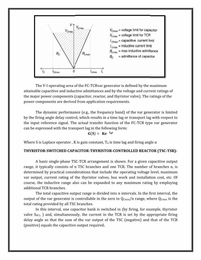
The V-I operating area of the FC-TCRvar generator is defined by the maximumattainable capacitive and inductive admittances and by the voltage and current ratings ofthe major power components (capacitor, reactor, and thyristor valve). The ratings of thepower components are derived from application requirements.The dynamic performance (e.g., the frequency band) of the var generator is limitedby the firing angle delay control, which results in a time lag or transport lag with respect tothe input reference signal. The actual transfer function of the FC-TCR type var generatorcan be expressed with the transport lag in the following form:( ) =Where S is Laplace operator , K is gain constant, Td is time lag and firing angle αTHYRISTOR-SWITCHED CAPACITOR-THYRISTOR-CONTROLLED REACTOR (TSC-TSR):A basic single-phase TSC-TCR arrangement is shown. For a given capacitive outputrange, it typically consists of n TSC branches and one TCR. The number of branches n, isdetermined by practical considerations that include the operating voltage level, maximumvar output, current rating of the thyristor valves, bus work and installation cost, etc. Ofcourse, the inductive range also can be expanded to any maximum rating by employingadditional TCR branches.The total capacitive output range is divided into n intervals. In the first interval, theoutput of the var generator is controllable in the zero to QCmax/n range, where QCmax is thetotal rating provided by all TSC branches.In this interval, one capacitor bank is switched in (by firing, for example, thyristorvalve SW1, ) and, simultaneously, the current in the TCR is set by the appropriate firingdelay angle so that the sum of the var output of the TSC (negative) and that of the TCR(positive) equals the capacitive output required.
The V-I operating area of the FC-TCRvar generator is defined by the maximumattainable capacitive and inductive admittances and by the voltage and current ratings ofthe major power components (capacitor, reactor, and thyristor valve). The ratings of thepower components are derived from application requirements.The dynamic performance (e.g., the frequency band) of the var generator is limitedby the firing angle delay control, which results in a time lag or transport lag with respect tothe input reference signal. The actual transfer function of the FC-TCR type var generatorcan be expressed with the transport lag in the following form:( ) =Where S is Laplace operator , K is gain constant, Td is time lag and firing angle αTHYRISTOR-SWITCHED CAPACITOR-THYRISTOR-CONTROLLED REACTOR (TSC-TSR):A basic single-phase TSC-TCR arrangement is shown. For a given capacitive outputrange, it typically consists of n TSC branches and one TCR. The number of branches n, isdetermined by practical considerations that include the operating voltage level, maximumvar output, current rating of the thyristor valves, bus work and installation cost, etc. Ofcourse, the inductive range also can be expanded to any maximum rating by employingadditional TCR branches.The total capacitive output range is divided into n intervals. In the first interval, theoutput of the var generator is controllable in the zero to QCmax/n range, where QCmax is thetotal rating provided by all TSC branches.In this interval, one capacitor bank is switched in (by firing, for example, thyristorvalve SW1, ) and, simultaneously, the current in the TCR is set by the appropriate firingdelay angle so that the sum of the var output of the TSC (negative) and that of the TCR(positive) equals the capacitive output required.
The V-I operating area of the FC-TCRvar generator is defined by the maximumattainable capacitive and inductive admittances and by the voltage and current ratings ofthe major power components (capacitor, reactor, and thyristor valve). The ratings of thepower components are derived from application requirements.The dynamic performance (e.g., the frequency band) of the var generator is limitedby the firing angle delay control, which results in a time lag or transport lag with respect tothe input reference signal. The actual transfer function of the FC-TCR type var generatorcan be expressed with the transport lag in the following form:( ) =Where S is Laplace operator , K is gain constant, Td is time lag and firing angle αTHYRISTOR-SWITCHED CAPACITOR-THYRISTOR-CONTROLLED REACTOR (TSC-TSR):A basic single-phase TSC-TCR arrangement is shown. For a given capacitive outputrange, it typically consists of n TSC branches and one TCR. The number of branches n, isdetermined by practical considerations that include the operating voltage level, maximumvar output, current rating of the thyristor valves, bus work and installation cost, etc. Ofcourse, the inductive range also can be expanded to any maximum rating by employingadditional TCR branches.The total capacitive output range is divided into n intervals. In the first interval, theoutput of the var generator is controllable in the zero to QCmax/n range, where QCmax is thetotal rating provided by all TSC branches.In this interval, one capacitor bank is switched in (by firing, for example, thyristorvalve SW1, ) and, simultaneously, the current in the TCR is set by the appropriate firingdelay angle so that the sum of the var output of the TSC (negative) and that of the TCR(positive) equals the capacitive output required.
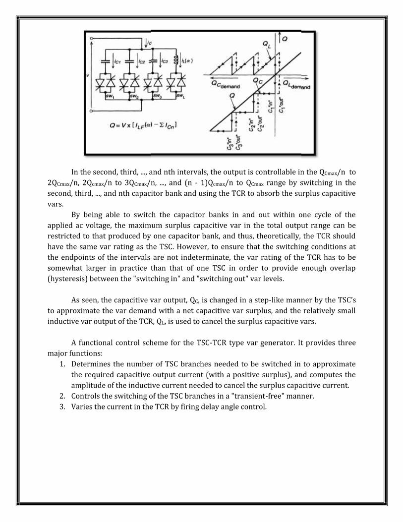
In the second, third, ..., and nth intervals, the output is controllable in the QCmax/n to2QCmax/n, 2Qcmax/n to 3QCmax/n, ..., and (n - 1)Qcmax/n to QCmax range by switching in thesecond, third, ..., and nth capacitor bank and using the TCR to absorb the surplus capacitivevars. By being able to switch the capacitor banks in and out within one cycle of theapplied ac voltage, the maximum surplus capacitive var in the total output range can berestricted to that produced by one capacitor bank, and thus, theoretically, the TCR shouldhave the same var rating as the TSC. However, to ensure that the switching conditions atthe endpoints of the intervals are not indeterminate, the var rating of the TCR has to besomewhat larger in practice than that of one TSC in order to provide enough overlap(hysteresis) between the "switching in" and "switching out" var levels.As seen, the capacitive var output, QC, is changed in a step-like manner by the TSC’sto approximate the var demand with a net capacitive var surplus, and the relatively smallinductive var output of the TCR, QL, is used to cancel the surplus capacitive vars.A functional control scheme for the TSC-TCR type var generator. It provides threemajor functions:1. Determines the number of TSC branches needed to be switched in to approximatethe required capacitive output current (with a positive surplus), and computes theamplitude of the inductive current needed to cancel the surplus capacitive current.2. Controls the switching of the TSC branches in a "transient-free" manner.3. Varies the current in the TCR by firing delay angle control.
In the second, third, ..., and nth intervals, the output is controllable in the QCmax/n to2QCmax/n, 2Qcmax/n to 3QCmax/n, ..., and (n - 1)Qcmax/n to QCmax range by switching in thesecond, third, ..., and nth capacitor bank and using the TCR to absorb the surplus capacitivevars. By being able to switch the capacitor banks in and out within one cycle of theapplied ac voltage, the maximum surplus capacitive var in the total output range can berestricted to that produced by one capacitor bank, and thus, theoretically, the TCR shouldhave the same var rating as the TSC. However, to ensure that the switching conditions atthe endpoints of the intervals are not indeterminate, the var rating of the TCR has to besomewhat larger in practice than that of one TSC in order to provide enough overlap(hysteresis) between the "switching in" and "switching out" var levels.As seen, the capacitive var output, QC, is changed in a step-like manner by the TSC’sto approximate the var demand with a net capacitive var surplus, and the relatively smallinductive var output of the TCR, QL, is used to cancel the surplus capacitive vars.A functional control scheme for the TSC-TCR type var generator. It provides threemajor functions:1. Determines the number of TSC branches needed to be switched in to approximatethe required capacitive output current (with a positive surplus), and computes theamplitude of the inductive current needed to cancel the surplus capacitive current.2. Controls the switching of the TSC branches in a "transient-free" manner.3. Varies the current in the TCR by firing delay angle control.
In the second, third, ..., and nth intervals, the output is controllable in the QCmax/n to2QCmax/n, 2Qcmax/n to 3QCmax/n, ..., and (n - 1)Qcmax/n to QCmax range by switching in thesecond, third, ..., and nth capacitor bank and using the TCR to absorb the surplus capacitivevars. By being able to switch the capacitor banks in and out within one cycle of theapplied ac voltage, the maximum surplus capacitive var in the total output range can berestricted to that produced by one capacitor bank, and thus, theoretically, the TCR shouldhave the same var rating as the TSC. However, to ensure that the switching conditions atthe endpoints of the intervals are not indeterminate, the var rating of the TCR has to besomewhat larger in practice than that of one TSC in order to provide enough overlap(hysteresis) between the "switching in" and "switching out" var levels.As seen, the capacitive var output, QC, is changed in a step-like manner by the TSC’sto approximate the var demand with a net capacitive var surplus, and the relatively smallinductive var output of the TCR, QL, is used to cancel the surplus capacitive vars.A functional control scheme for the TSC-TCR type var generator. It provides threemajor functions:1. Determines the number of TSC branches needed to be switched in to approximatethe required capacitive output current (with a positive surplus), and computes theamplitude of the inductive current needed to cancel the surplus capacitive current.2. Controls the switching of the TSC branches in a "transient-free" manner.3. Varies the current in the TCR by firing delay angle control.
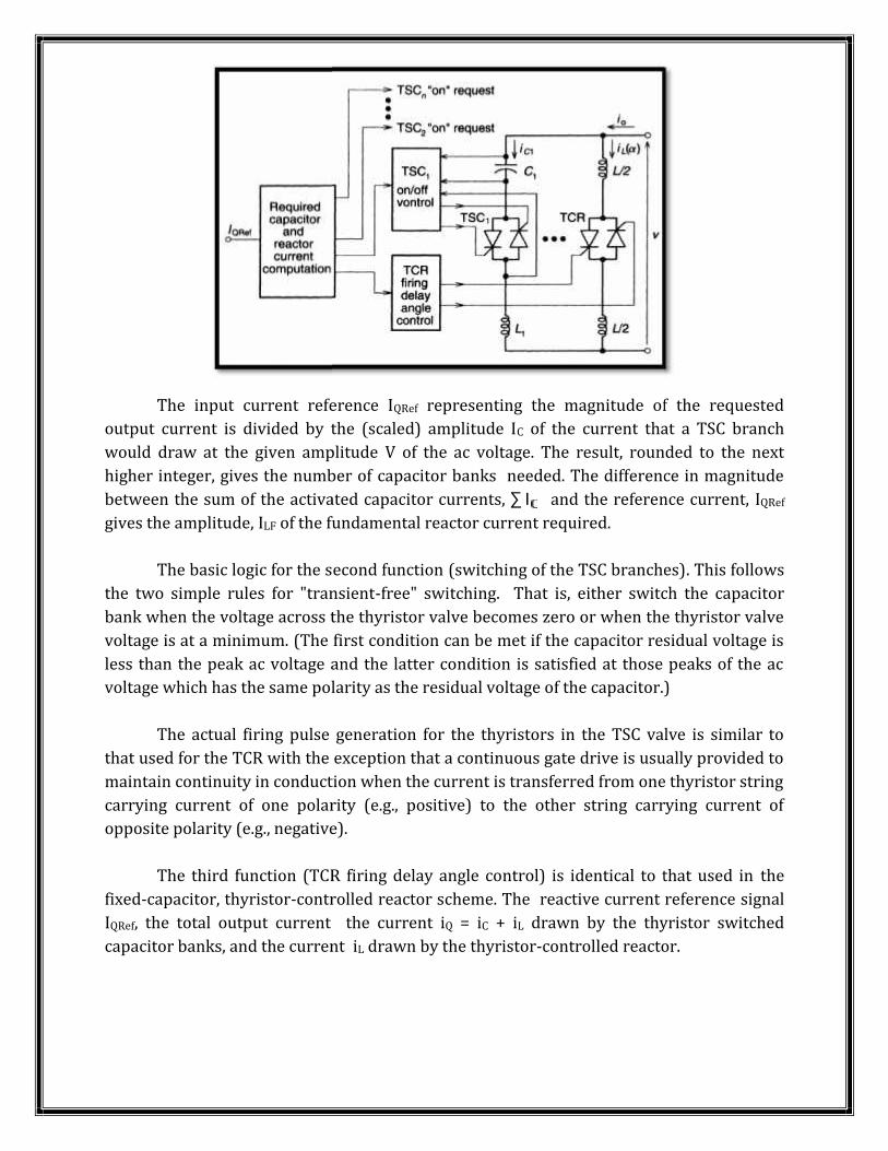
The input current reference IQRef representing the magnitude of the requestedoutput current is divided by the (scaled) amplitude IC of the current that a TSC branchwould draw at the given amplitude V of the ac voltage. The result, rounded to the nexthigher integer, gives the number of capacitor banks needed. The difference in magnitudebetween the sum of the activated capacitor currents, ∑ I and the reference current, IQRefgives the amplitude, ILF of the fundamental reactor current required.The basic logic for the second function (switching of the TSC branches). This followsthe two simple rules for "transient-free" switching. That is, either switch the capacitorbank when the voltage across the thyristor valve becomes zero or when the thyristor valvevoltage is at a minimum. (The first condition can be met if the capacitor residual voltage isless than the peak ac voltage and the latter condition is satisfied at those peaks of the acvoltage which has the same polarity as the residual voltage of the capacitor.)The actual firing pulse generation for the thyristors in the TSC valve is similar tothat used for the TCR with the exception that a continuous gate drive is usually provided tomaintain continuity in conduction when the current is transferred from one thyristor stringcarrying current of one polarity (e.g., positive) to the other string carrying current ofopposite polarity (e.g., negative).The third function (TCR firing delay angle control) is identical to that used in thefixed-capacitor, thyristor-controlled reactor scheme. The reactive current reference signalIQRef, the total output current the current iQ = iC + iL drawn by the thyristor switchedcapacitor banks, and the current iL drawn by the thyristor-controlled reactor.
The input current reference IQRef representing the magnitude of the requestedoutput current is divided by the (scaled) amplitude IC of the current that a TSC branchwould draw at the given amplitude V of the ac voltage. The result, rounded to the nexthigher integer, gives the number of capacitor banks needed. The difference in magnitudebetween the sum of the activated capacitor currents, ∑ I and the reference current, IQRefgives the amplitude, ILF of the fundamental reactor current required.The basic logic for the second function (switching of the TSC branches). This followsthe two simple rules for "transient-free" switching. That is, either switch the capacitorbank when the voltage across the thyristor valve becomes zero or when the thyristor valvevoltage is at a minimum. (The first condition can be met if the capacitor residual voltage isless than the peak ac voltage and the latter condition is satisfied at those peaks of the acvoltage which has the same polarity as the residual voltage of the capacitor.)The actual firing pulse generation for the thyristors in the TSC valve is similar tothat used for the TCR with the exception that a continuous gate drive is usually provided tomaintain continuity in conduction when the current is transferred from one thyristor stringcarrying current of one polarity (e.g., positive) to the other string carrying current ofopposite polarity (e.g., negative).The third function (TCR firing delay angle control) is identical to that used in thefixed-capacitor, thyristor-controlled reactor scheme. The reactive current reference signalIQRef, the total output current the current iQ = iC + iL drawn by the thyristor switchedcapacitor banks, and the current iL drawn by the thyristor-controlled reactor.
The input current reference IQRef representing the magnitude of the requestedoutput current is divided by the (scaled) amplitude IC of the current that a TSC branchwould draw at the given amplitude V of the ac voltage. The result, rounded to the nexthigher integer, gives the number of capacitor banks needed. The difference in magnitudebetween the sum of the activated capacitor currents, ∑ I and the reference current, IQRefgives the amplitude, ILF of the fundamental reactor current required.The basic logic for the second function (switching of the TSC branches). This followsthe two simple rules for "transient-free" switching. That is, either switch the capacitorbank when the voltage across the thyristor valve becomes zero or when the thyristor valvevoltage is at a minimum. (The first condition can be met if the capacitor residual voltage isless than the peak ac voltage and the latter condition is satisfied at those peaks of the acvoltage which has the same polarity as the residual voltage of the capacitor.)The actual firing pulse generation for the thyristors in the TSC valve is similar tothat used for the TCR with the exception that a continuous gate drive is usually provided tomaintain continuity in conduction when the current is transferred from one thyristor stringcarrying current of one polarity (e.g., positive) to the other string carrying current ofopposite polarity (e.g., negative).The third function (TCR firing delay angle control) is identical to that used in thefixed-capacitor, thyristor-controlled reactor scheme. The reactive current reference signalIQRef, the total output current the current iQ = iC + iL drawn by the thyristor switchedcapacitor banks, and the current iL drawn by the thyristor-controlled reactor.
...
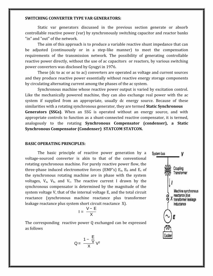
SWITCHING CONVERTER TYPE VAR GENERATORS:Static var generators discussed in the previous section generate or absorbcontrollable reactive power (var) by synchronously switching capacitor and reactor banks"in" and "out" of the network.The aim of this approach is to produce a variable reactive shunt impedance that canbe adjusted (continuously or in a step-like manner) to meet the compensationrequirements of the transmission network. The possibility of generating controllablereactive power directly, without the use of ac capacitors or reactors, by various switchingpower converters was disclosed by Gyugyi in 1976.These (dc to ac or ac to ac) converters are operated as voltage and current sourcesand they produce reactive power essentially without reactive energy storage componentsby circulating alternating current among the phases of the ac system.Synchronous machine whose reactive power output is varied by excitation control.Like the mechanically powered machine, they can also exchange real power with the acsystem if supplied from an appropriate, usually dc energy source. Because of thesesimilarities with a rotating synchronous generator, they are termed Static SynchronousGenerators (SSGs). When an SSG is operated without an energy source, and withappropriate controls to function as a shunt-connected reactive compensator, it is termed,analogously to the rotating Synchronous Compensator (condenser), a StaticSynchronous Compensator (Condenser) STATCOM STATCON.
BASIC OPERATING PRINCIPLES:The basic principle of reactive power generation by avoltage-sourced converter is akin to that of the conventionalrotating synchronous machine. For purely reactive power flow, thethree-phase induced electromotive forces (EMF’s) Ea, Eb and Ec ofthe synchronous rotating machine are in phase with the systemvoltages, Va, Vb, and Vc. The reactive current I drawn by thesynchronous compensator is determined by the magnitude of thesystem voltage V, that of the internal voltage E, and the total circuitreactance (synchronous machine reactance plus transformerleakage reactance plus system short circuit reactance X).I = V − EXThe corresponding reactive power Q exchanged can be expressedas followsQ = 1 − EVX V
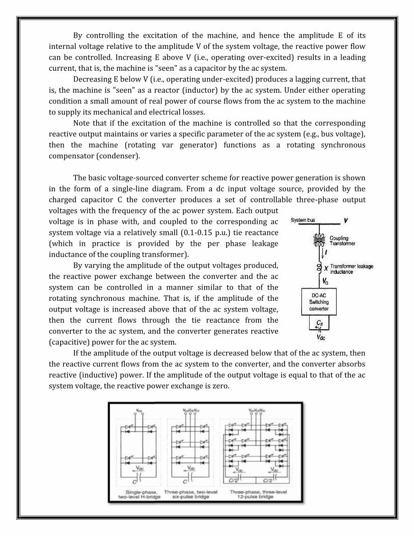
By controlling the excitation of the machine, and hence the amplitude E of itsinternal voltage relative to the amplitude V of the system voltage, the reactive power flowcan be controlled. Increasing E above V (i.e., operating over-excited) results in a leadingcurrent, that is, the machine is "seen" as a capacitor by the ac system.Decreasing E below V (i.e., operating under-excited) produces a lagging current, thatis, the machine is "seen" as a reactor (inductor) by the ac system. Under either operatingcondition a small amount of real power of course flows from the ac system to the machineto supply its mechanical and electrical losses.Note that if the excitation of the machine is controlled so that the correspondingreactive output maintains or varies a specific parameter of the ac system (e.g., bus voltage),then the machine (rotating var generator) functions as a rotating synchronouscompensator (condenser).The basic voltage-sourced converter scheme for reactive power generation is shownin the form of a single-line diagram. From a dc input voltage source, provided by thecharged capacitor C the converter produces a set of controllable three-phase outputvoltages with the frequency of the ac power system. Each outputvoltage is in phase with, and coupled to the corresponding acsystem voltage via a relatively small (0.1-0.15 p.u.) tie reactance(which in practice is provided by the per phase leakageinductance of the coupling transformer).By varying the amplitude of the output voltages produced,the reactive power exchange between the converter and the acsystem can be controlled in a manner similar to that of therotating synchronous machine. That is, if the amplitude of theoutput voltage is increased above that of the ac system voltage,then the current flows through the tie reactance from theconverter to the ac system, and the converter generates reactive(capacitive) power for the ac system.If the amplitude of the output voltage is decreased below that of the ac system, thenthe reactive current flows from the ac system to the converter, and the converter absorbsreactive (inductive) power. If the amplitude of the output voltage is equal to that of the acsystem voltage, the reactive power exchange is zero.
By controlling the excitation of the machine, and hence the amplitude E of itsinternal voltage relative to the amplitude V of the system voltage, the reactive power flowcan be controlled. Increasing E above V (i.e., operating over-excited) results in a leadingcurrent, that is, the machine is "seen" as a capacitor by the ac system.Decreasing E below V (i.e., operating under-excited) produces a lagging current, thatis, the machine is "seen" as a reactor (inductor) by the ac system. Under either operatingcondition a small amount of real power of course flows from the ac system to the machineto supply its mechanical and electrical losses.Note that if the excitation of the machine is controlled so that the correspondingreactive output maintains or varies a specific parameter of the ac system (e.g., bus voltage),then the machine (rotating var generator) functions as a rotating synchronouscompensator (condenser).The basic voltage-sourced converter scheme for reactive power generation is shownin the form of a single-line diagram. From a dc input voltage source, provided by thecharged capacitor C the converter produces a set of controllable three-phase outputvoltages with the frequency of the ac power system. Each outputvoltage is in phase with, and coupled to the corresponding acsystem voltage via a relatively small (0.1-0.15 p.u.) tie reactance(which in practice is provided by the per phase leakageinductance of the coupling transformer).By varying the amplitude of the output voltages produced,the reactive power exchange between the converter and the acsystem can be controlled in a manner similar to that of therotating synchronous machine. That is, if the amplitude of theoutput voltage is increased above that of the ac system voltage,then the current flows through the tie reactance from theconverter to the ac system, and the converter generates reactive(capacitive) power for the ac system.If the amplitude of the output voltage is decreased below that of the ac system, thenthe reactive current flows from the ac system to the converter, and the converter absorbsreactive (inductive) power. If the amplitude of the output voltage is equal to that of the acsystem voltage, the reactive power exchange is zero.
By controlling the excitation of the machine, and hence the amplitude E of itsinternal voltage relative to the amplitude V of the system voltage, the reactive power flowcan be controlled. Increasing E above V (i.e., operating over-excited) results in a leadingcurrent, that is, the machine is "seen" as a capacitor by the ac system.Decreasing E below V (i.e., operating under-excited) produces a lagging current, thatis, the machine is "seen" as a reactor (inductor) by the ac system. Under either operatingcondition a small amount of real power of course flows from the ac system to the machineto supply its mechanical and electrical losses.Note that if the excitation of the machine is controlled so that the correspondingreactive output maintains or varies a specific parameter of the ac system (e.g., bus voltage),then the machine (rotating var generator) functions as a rotating synchronouscompensator (condenser).The basic voltage-sourced converter scheme for reactive power generation is shownin the form of a single-line diagram. From a dc input voltage source, provided by thecharged capacitor C the converter produces a set of controllable three-phase outputvoltages with the frequency of the ac power system. Each outputvoltage is in phase with, and coupled to the corresponding acsystem voltage via a relatively small (0.1-0.15 p.u.) tie reactance(which in practice is provided by the per phase leakageinductance of the coupling transformer).By varying the amplitude of the output voltages produced,the reactive power exchange between the converter and the acsystem can be controlled in a manner similar to that of therotating synchronous machine. That is, if the amplitude of theoutput voltage is increased above that of the ac system voltage,then the current flows through the tie reactance from theconverter to the ac system, and the converter generates reactive(capacitive) power for the ac system.If the amplitude of the output voltage is decreased below that of the ac system, thenthe reactive current flows from the ac system to the converter, and the converter absorbsreactive (inductive) power. If the amplitude of the output voltage is equal to that of the acsystem voltage, the reactive power exchange is zero.
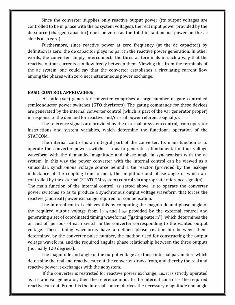
Since the converter supplies only reactive output power (its output voltages arecontrolled to be in phase with the ac system voltages), the real input power provided by thede source (charged capacitor) must be zero (as the total instantaneous power on the acside is also zero).Furthermore, since reactive power at zero frequency (at the dc capacitor) bydefinition is zero, the de capacitor plays no part in the reactive power generation. In otherwords, the converter simply interconnects the three ac terminals in such a way that thereactive output currents can flow freely between them. Viewing this from the terminals ofthe ac system, one could say that the converter establishes a circulating current flowamong the phases with zero net instantaneous power exchange.
BASIC CONTROL APPROACHES:A static (var) generator converter comprises a large number of gate controlledsemiconductor power switches (GTO thyristors). The gating commands for these devicesare generated by the internal converter control (which is part of the var generator proper)in response to the demand for reactive and/or real power reference signal(s).The reference signals are provided by the external or system control, from operatorinstructions and system variables, which determine the functional operation of theSTATCOM.The internal control is an integral part of the converter. Its main function is tooperate the converter power switches so as to generate a fundamental output voltagewaveform with the demanded magnitude and phase angle in synchronism with the acsystem. In this way the power converter with the internal control can be viewed as asinusoidal, synchronous voltage source behind a tie reactor (provided by the leakageinductance of the coupling transformer), the amplitude and phase angle of which arecontrolled by the external (STATCOM system) control via appropriate reference signal(s).The main function of the internal control, as stated above, is to operate the converterpower switches so as to produce a synchronous output voltage waveform that forces thereactive (and real) power exchange required for compensation.The internal control achieves this by computing the magnitude and phase angle ofthe required output voltage from IQRef and IPRef provided by the external control andgenerating a set of coordinated timing waveforms ("gating pattern"), which determines theon and off periods of each switch in the converter corresponding to the wanted outputvoltage. These timing waveforms have a defined phase relationship between them,determined by the converter pulse number, the method used for constructing the outputvoltage waveform, and the required angular phase relationship between the three outputs(normally 120 degrees).The magnitude and angle of the output voltage are those internal parameters whichdetermine the real and reactive current the converter draws from, and thereby the real andreactive power it exchanges with the ac system.If the converter is restricted for reactive power exchange, i.e., it is strictly operatedas a static var generator, then the reference input to the internal control is the requiredreactive current. From this the internal control derives the necessary magnitude and angle
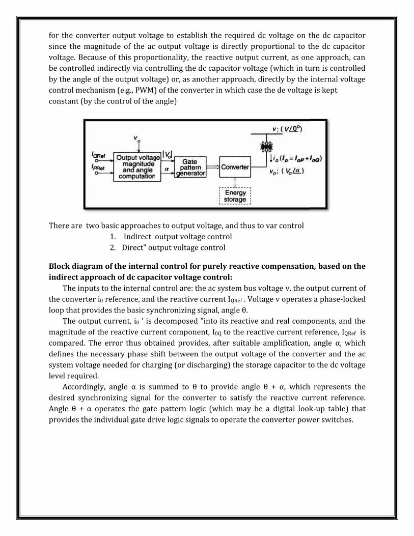
for the converter output voltage to establish the required dc voltage on the dc capacitorsince the magnitude of the ac output voltage is directly proportional to the dc capacitorvoltage. Because of this proportionality, the reactive output current, as one approach, canbe controlled indirectly via controlling the dc capacitor voltage (which in turn is controlledby the angle of the output voltage) or, as another approach, directly by the internal voltagecontrol mechanism (e.g., PWM) of the converter in which case the de voltage is keptconstant (by the control of the angle)
There are two basic approaches to output voltage, and thus to var control1. Indirect output voltage control2. Direct" output voltage controlBlock diagram of the internal control for purely reactive compensation, based on theindirect approach of dc capacitor voltage control:The inputs to the internal control are: the ac system bus voltage v, the output current ofthe converter i0 reference, and the reactive current IQRef . Voltage v operates a phase-lockedloop that provides the basic synchronizing signal, angle θ.The output current, i0 ' is decomposed "into its reactive and real components, and themagnitude of the reactive current component, I0Q to the reactive current reference, IQRef iscompared. The error thus obtained provides, after suitable amplification, angle α, whichdefines the necessary phase shift between the output voltage of the converter and the acsystem voltage needed for charging (or discharging) the storage capacitor to the dc voltagelevel required.Accordingly, angle α is summed to θ to provide angle θ + α, which represents thedesired synchronizing signal for the converter to satisfy the reactive current reference.Angle θ + α operates the gate pattern logic (which may be a digital look-up table) thatprovides the individual gate drive logic signals to operate the converter power switches.
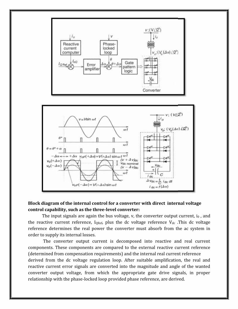
Block diagram of the internal control for a converter with direct internal voltagecontrol capability, such as the three-level converter:The input signals are again the bus voltage, v, the converter output current, i0 , andthe reactive current reference, IQRef, plus the dc voltage reference Vdc .This dc voltagereference determines the real power the converter must absorb from the ac system inorder to supply its internal losses.The converter output current is decomposed into reactive and real currentcomponents. These components are compared to the external reactive current reference(determined from compensation requirements) and the internal real current referencederived from the dc voltage regulation loop. After suitable amplification, the real andreactive current error signals are converted into the magnitude and angle of the wantedconverter output voltage, from which the appropriate gate drive signals, in properrelationship with the phase-locked loop provided phase reference, are derived.
Block diagram of the internal control for a converter with direct internal voltagecontrol capability, such as the three-level converter:The input signals are again the bus voltage, v, the converter output current, i0 , andthe reactive current reference, IQRef, plus the dc voltage reference Vdc .This dc voltagereference determines the real power the converter must absorb from the ac system inorder to supply its internal losses.The converter output current is decomposed into reactive and real currentcomponents. These components are compared to the external reactive current reference(determined from compensation requirements) and the internal real current referencederived from the dc voltage regulation loop. After suitable amplification, the real andreactive current error signals are converted into the magnitude and angle of the wantedconverter output voltage, from which the appropriate gate drive signals, in properrelationship with the phase-locked loop provided phase reference, are derived.
Block diagram of the internal control for a converter with direct internal voltagecontrol capability, such as the three-level converter:The input signals are again the bus voltage, v, the converter output current, i0 , andthe reactive current reference, IQRef, plus the dc voltage reference Vdc .This dc voltagereference determines the real power the converter must absorb from the ac system inorder to supply its internal losses.The converter output current is decomposed into reactive and real currentcomponents. These components are compared to the external reactive current reference(determined from compensation requirements) and the internal real current referencederived from the dc voltage regulation loop. After suitable amplification, the real andreactive current error signals are converted into the magnitude and angle of the wantedconverter output voltage, from which the appropriate gate drive signals, in properrelationship with the phase-locked loop provided phase reference, are derived.
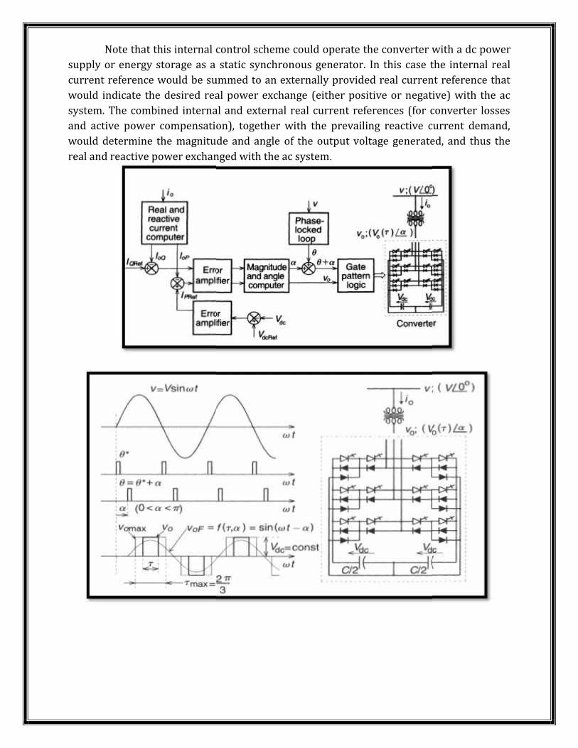
Note that this internal control scheme could operate the converter with a dc powersupply or energy storage as a static synchronous generator. In this case the internal realcurrent reference would be summed to an externally provided real current reference thatwould indicate the desired real power exchange (either positive or negative) with the acsystem. The combined internal and external real current references (for converter lossesand active power compensation), together with the prevailing reactive current demand,would determine the magnitude and angle of the output voltage generated, and thus thereal and reactive power exchanged with the ac system.
Note that this internal control scheme could operate the converter with a dc powersupply or energy storage as a static synchronous generator. In this case the internal realcurrent reference would be summed to an externally provided real current reference thatwould indicate the desired real power exchange (either positive or negative) with the acsystem. The combined internal and external real current references (for converter lossesand active power compensation), together with the prevailing reactive current demand,would determine the magnitude and angle of the output voltage generated, and thus thereal and reactive power exchanged with the ac system.
Note that this internal control scheme could operate the converter with a dc powersupply or energy storage as a static synchronous generator. In this case the internal realcurrent reference would be summed to an externally provided real current reference thatwould indicate the desired real power exchange (either positive or negative) with the acsystem. The combined internal and external real current references (for converter lossesand active power compensation), together with the prevailing reactive current demand,would determine the magnitude and angle of the output voltage generated, and thus thereal and reactive power exchanged with the ac system.
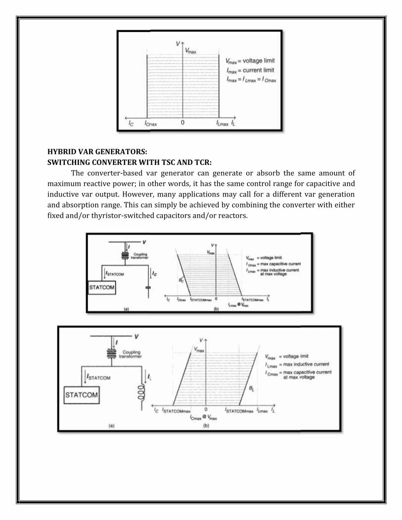
HYBRID VAR GENERATORS:SWITCHING CONVERTER WITH TSC AND TCR:The converter-based var generator can generate or absorb the same amount ofmaximum reactive power; in other words, it has the same control range for capacitive andinductive var output. However, many applications may call for a different var generationand absorption range. This can simply be achieved by combining the converter with eitherfixed and/or thyristor-switched capacitors and/or reactors.
HYBRID VAR GENERATORS:SWITCHING CONVERTER WITH TSC AND TCR:The converter-based var generator can generate or absorb the same amount ofmaximum reactive power; in other words, it has the same control range for capacitive andinductive var output. However, many applications may call for a different var generationand absorption range. This can simply be achieved by combining the converter with eitherfixed and/or thyristor-switched capacitors and/or reactors.
HYBRID VAR GENERATORS:SWITCHING CONVERTER WITH TSC AND TCR:The converter-based var generator can generate or absorb the same amount ofmaximum reactive power; in other words, it has the same control range for capacitive andinductive var output. However, many applications may call for a different var generationand absorption range. This can simply be achieved by combining the converter with eitherfixed and/or thyristor-switched capacitors and/or reactors.
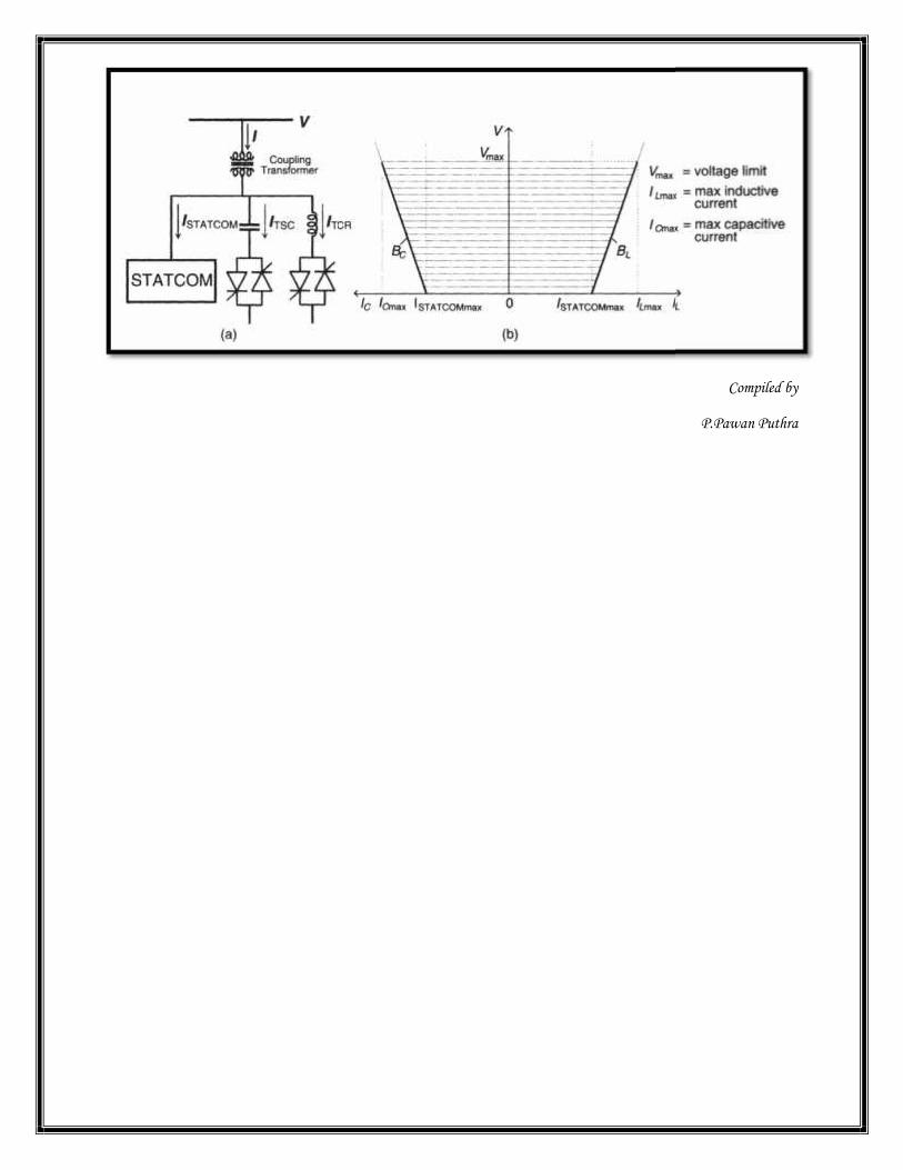
Compiled by
P.Pawan Puthra
Compiled by
P.Pawan Puthra
Compiled by
P.Pawan Puthra