Embed Size (px)
Citation preview
IOSR Journal of Electrical and Electronics Engineering (IOSR-JEEE)
e-ISSN: 2278-1676,p-ISSN: 2320-3331, Volume 12, Issue 4 Ver. I (Jul. – Aug. 2017), PP 54-66
www.iosrjournals.org
DOI: 10.9790/1676-1204015466 www.iosrjournals.org 54 | Page
Optimal Reactive Power Compensation in Transmission Networks By
TCSC Using Particle Swarm Optimization
Subhash Shankar Zope1, Dr. R. P. Singh2
1,2Computer Science and Engineering
1,2Sri Satya Sai University of Technology & Medical Sciences
1,2Opposite OILFED, Bhopal Indore Highway, Pachama, Sehore (India) 466001
Abstract: Increased demand for electrical energy and free market economies for electricity exchange, have pushed
power suppliers to pay a great attention to quality and cost of the latter, especially in transmission networks. To
reduce power losses due to the high level of the reactive currents transit and improve the voltage profile in
transmission systems, shunt capacitor banks are widely used. The problem to be solved is to find the capacitors
optimal number, sizes and locations so that they maximize the cost reduction. This paper is constructed as a function
of active and reactive power loss reduction. To solve this constrained non-linear problem, a heuristic technique,
based on the sensitivity factors of the system power losses, has been proposed. The optimal location TCSC is studied
on the basis of Particle Swarm Optimization (PSO) to minimize network losses. Validation of the proposed
implementation is done on the IEEE-14 and IEEE-30 bus systems.
Keywords: FACTS,PSO, TCSC
---------------------------------------------------------------------------------------------------------------------------------------
Date of Submission: 12-09-2017 Date of acceptance: 21-09-2017
---------------------------------------------------------------------------------------------------------------------------------------
I. Introduction The FACTS by means of the acronym "Flexible Alternating Current Transmission System" are devices that
by means of the activation of semiconductor elements of power, allow to improve the capacity of power transfer
between a point of consumption and one of generation, for this purpose the variables of the system influenced by the
flexible compensators are, the voltages of the nodes, the series impedances of the lines or the phase angles. In any
case it is translated. In a control of active and reactive power flows, although the one of more interest usually is the
decrease of the reactive one. Characteristically the FACTS present advantages over traditional methods of control
reagents in power systems, by the ability to intermittent in short and repetitive time periods that are mainly dependent
on the variability of the system demand [1]. When the network is disturbed (Short circuit, loss of a load or a group,
opening of a line, etc.), the difference between the mechanical and electrical powers leads to an acceleration or
deceleration which may lead to the loss of synchronism of one or more generation groups. The rotor angles oscillate
until the adjustment systems protection in order to restore the march in synchronism and lead the network to a state of
stable operation. However, the demand for electricity varies constantly over the course of a schedules, weather
conditions, other criteria are also taken into account such as holiday periods, holidays, weekends, holidays and events
that (strikes, sporting events, etc.). For this purpose the design of the electrical system has been made in such a way
that an entire inseparable chain is integrated beginning with: production, transport and distribution to consumers. You
cannot store large quantities of energy in electrical form, it is the problem is forced to produce the same quantity of
electricity that must be consumed; we also know that the production groups have certain technical limitations which
must not be exceeded which leads us to another problem too complicated one can translate it mathematically a non-
linear problem [2]. Therefore, the economic distribution of electric power produced by power stations at particular
marginal cost; has become the object of research and studies over the years. This process has been under study since
1928 due to its great importance in electric power; the numerous publications on this subject are clear proof. Several
methods and algorithms have been applied to solve this problem achieving better results. Early research has neglected
losses in lines subsequently several improvements of the original proposal have been developed by introducing the
losses as well as the operating limits of the production groups. Arriving at their final shapes; algorithms based on
marginal costs take into account:
Fuel costs and their efficiencies.
Operating and maintenance costs.
Operating limits and operating areas prohibited.
Unit response gradients.
Transmission losses (penalty factors).
Reserve constraints.
These algorithms prove their efficiencies and provide better results, but another result is the time factor.
Thanks to the development of "smart grids", a transition has been made towards a market more dynamic, fast and
efficient. Recently, the techniques of neural networks are beginning to be used in different fields of study of electrical
networks, including forecasts of consumption, load distribution and Economic Dispatch. The use of the method of

Optimal Reactive Power Compensation In Transmission Networks By Tcsc Using Particle Swarm ..
DOI: 10.9790/1676-1204015466 www.iosrjournals.org 55 | Page
neural networks makes it possible to avoid the disadvantages encountered by classical methods and more precisely
lost time; as well as this method is convenient to take into account the various non-linear and random factors.
1.1 Control of Transits
In a mesh interconnection network, the distribution of energy transits depends essentially:
Location of loads.
The location of production groups in operation.
Cross-border trade.
Location of reactive energy compensation means.
Impedances of the transport structures.
These transits of energy constitute a flow from the stations where customers are connected; it borrows the
lines and the transport cables in distributing in proportion to the inverse of their impedance. What is, in a way, a
preference marked for the "shortest path". This flow of energy is materialized by the current crosses the structures.
The higher the energy flow, the more current currents will be strong. These intensities may increase, particularly when
a structure is triggered by a defect. Indeed, the transit initially supported by this structure will be referred to the
neighbour’s structures; it is the phenomenon of transfer of charge.
The regulation of transits is ensured by playing mainly on two parameters:
Topology of the Network: By adapting the operating diagrams, the dispatcher modifies the impedances of the
different meshes of the network (creation of long queues to increase the impedance of the network or, on the contrary,
works in order to reduce it) and plays on the distribution of production sources.
Production Programs: By adapting the production programs of the groups, the dispatcher plays on the distribution of
sources of production versus loads. In the ultimate situation, the last resort is to act on the charges by shedding
customers. For a given topology, it is possible to evaluate, using the driving and simulation tools, the transits in each
of the works according to the adopted production plan and the location charges. In the same way, it is possible to
calculate the impact of the triggering of a transport structure or production, on the value of transits in the remaining
works [3] [4].
II. State Of The Art A very large part of the losses of power in the electrical networks are attributed to those of distribution. Out
of all the power conveyed by distribution networks, power losses are estimated at 14%. The level of these losses
combined with the deregulation of the electricity market has prompted the distribution companies to give serious
consideration to the problem of losses in distribution networks in order to increase power transmission before thinking
about Invest in the construction of new lines. For a given line configuration and given that the active power demand is
incompressible, the reduction of voltage drops and that of power losses can only be achieved by reducing the transit of
the strong reactive components of the line current. For this purpose reactive energy compensation is recommended
and one of the most indicated means is the application of shunt capacitor batteries which is the subject of the present
disclosure. However, it is not enough to place batteries of capacitors to say that the problem posed (circulation of
strong reactive currents) is solved. The optimization of the reactive energy compensation is to be understood as the
choice of the powers of the capacitor banks, their locations and even the time during which they will remain in line if
it is an adaptive compensation. Of course, these choices must be made so that there is the least power loss in line and
an improvement in the voltage profile while having a positive economic return. The choices of the objective function
are dictated by the concern to take into account both the electrical and economic aspects of the problem. The objective
function on which all the authors who have dealt with the problem of optimization of reactive energy compensation is
the so-called economic return function (saving function). However, since the installation of the capacitor banks
reduces not only the active losses but also the losses of reactive power then, unlike all the authors who have dealt with
the problem that is research concern, this paper will introduce into the objective function the reduction of reactive
power losses.The objective is therefore to determine the powers of the batteries and their locations in order to
minimize power losses, improve the voltage profile and thereby increase the transmission capacity of these lines.
Since the problem of optimizing the reactive energy compensation cannot be separated from the power flow then the
solution of the latter will be studied. A significant number of works have addressed the problem of optimizing the
reactive energy compensation in distribution lines, i.e. determining capacitor bank sizes and their locations to reduce
power losses in the line. Methods can be classified into four categories: analytics, numerical programming, heuristics,
and intelligence and meta-heuristics.
III. Analytical Methods The pioneer in the field is Cook [5]. In 1959, he studied the effects of capacitors on power losses in a radial
distribution network where the charges are uniformly distributed. It considered the reduction of power losses as an
objective function by considering a periodic reactive charging cycle. Cook then developed a network of convenient
curves to determine the most economical power of the capacitor bank and the location of the capacitor bank on the
line. The development of methods has led researchers to become increasingly interested in the optimization of reactive
energy compensation. Therefore, they have developed numerical methods for the analysis of the electrical network.
Duran [6] in 1968 used a dynamic programming approach to solve the problem of reactive energy compensation in
Optimal Reactive Power Compensation In Transmission Networks By Tcsc Using Particle Swarm ..
DOI: 10.9790/1676-1204015466 www.iosrjournals.org 56 | Page
distribution networks where charges are discrete. The method evaluates the desirability of placing a capacitor bank or
not at the different nodes of the network. It then uses the following objective function and exploits the fact that it is
Markovian. In 1983, Ponnavaikko and Prakasa Rao [7] presented a method for determining the optimum powers of
fixed and switchable capacitor banks to be placed on a distribution network by a so-called local variation method. In
this method, changes are made to the size of the battery placed at any node "i" by keeping the rest of the batteries
unchanged and checking whether this change improves the objective function and whether the solution satisfies the
constraints. If this is the case, the solution is retained and the second battery is switched to the last installed battery.
Rinker and these teams [8] in 1988, proposed a method for the optimal placement of capacitor banks in
distribution networks. They set up for this purpose recorders to determine the average consumption of a week this
average week is used to determine the best reactive energy compensation scheme. They then try a combination of
fixed and / or switchable batteries in one or more nodes of the network and determine the reduction of power losses. If
the batteries give results in agreement with the five best combinations retained during the recordings, they are retained
as a solution of the problem.
Baran and Wu [9] in 1988, presented a method for solving the problem of placing capacitor banks in
distribution networks. In this problem, the locations of the batteries, their sizes, their types, the stresses of the voltage
and the variations of the load are taken into account. The problem is considered to be a non-linear programming
problem where load flow is explicitly represented.
To solve this problem, it is broken down into a slave problem and a master problem. They exploit for this purpose the
property of optimization where:
min𝑒∈𝐸,𝑢∈𝑈 𝑓 𝑢, 𝑒 = min𝑒∈𝑅 inf𝑢∈𝑈 𝑓(𝑒, 𝑢) (1)
The calculation of the power flow first concerned the transmission or transmission networks. Newtonian methods
were then developed to solve the problem of power flow in the latter. Among these methods are the Newton-Raphson
method [10] and the fast decoupled Newton-Raphson method [11]. Attempts have been made to apply these methods
to the distribution networks but, since they diverge in the majority of cases due to the characteristics of these
networks, the configuration of which is radial, a large number of nodes and Branch, and especially since the R/X
ratios of the latter are very high. The topology of distribution networks has been exploited for some authors to develop
the technique of double-scanning of the line (backward / forward sweep technique). In recent decades particular
interest has been given to the distribution networks and to the calculation of the power flow which produces a
literature review of the methods developed for this purpose will be given in the paragraph that follows.
IV. Literature Review In recent decades, a number of techniques have been developed to resolve the issue of power flow in
distribution networks. Since it is not possible to give all the work carried out in this direction, it will be sufficient to
describe some of them only. Among the authors who dealt with this problem is Goswami [12] in 1991 gave a solution
of power flow in radial and weakly meshed distribution networks. When the network is meshed, the meshes are
broken and fictitious nodes are created, these nodes whose number of loops and the power flowing there are negative.
The model of load considered is the model with constant impedance. In [13] Das in 1995 proposed a method for
solving recursive relations, a function of the tensions based on scanning up and down the line. Abdul Rahman [14] in
1995 also proposed an iterative method. It uses the fundamental principles of theory of equivalent circuits of
Thevenin, to determine the factors of stability of the tension whose determination requires the knowledge of the
tensions of the nodes therefore the solution of the flow of charge. Haque in [15] in 1996 proposed an iterative method
that applies both to radial networks and to weakly meshed networks. It then converts the network if it is meshed, into
a radial network by breaking the meshes thus creating fictive nodes whose number is equal to that of the loops and
where the powers which circulate there are negative. Then, it determines the tensions of the nodes and their phases at
the origin by sweeping the line up and down. It initializes the tensions of all nodes to that of the source whose relative
value is equal to one. Thukaram in [16] presented a formulation and algorithm to solve the problem of power flow, for
large three-phase lines. The solution technique is based on sweeping up and down the line. Gosh [17] in 1999 which
will give a method involving the evaluation of simple algebraic expression. The method that it proposes is iterative
and or at the first iteration the tensions of the nodes are initialized to 1 in relative value. It then calculates the load
currents and the branch currents as a result of which it determines the voltages of the nodes. Mok in [18] in 2000
examined the effects of different load models the convergence of the power flow method. The technique on which it
was developed has been implemented and presented as a software called "distriflow" capable of performing power
flux analysis for a radial distribution network of any number of busbars. Haque [19] in 2000 developed a method for
calculating power flow in distribution networks where multiple sources operate. The method of solution is identical to
that given in reference [15]. It considers, for the solution, of problem, that the network is single source. The rest of the
sources are simulated by an injection of power at the points of their connections (negative powers). Aravindhababu
[20] in 2001 also proposed an iterative method in which the tensions of the nodes are assumed to be equal to that of
the voltage source (1 pu). He first gave the shape of the branch-to-node incidence matrix, then he calculated the
branch currents and the node tensions. As a criterion of convergence, he proposed the difference between the tensions
of two successive iterations. Augugliaro and Dusonchet [21] in 2001 used an iterative method of scanning the line up
and down with the convergence of the load flow calculation algorithm. To accelerate the convergence, they choose
values for the initial voltages of values close to their final values. This choice makes it possible to reduce the number

Optimal Reactive Power Compensation In Transmission Networks By Tcsc Using Particle Swarm ..
DOI: 10.9790/1676-1204015466 www.iosrjournals.org 57 | Page
of iterations and thus the computation time to reach the solution. Moreover, the authors in question determine the
topology of the network by using the incidence matrix branches to nodes whose generic elements are equal to zero
and one. Mekhamer in [22] in 2002 used the equations developed by Baran and Wu [23] for each node of the line but
with different procedures. In this method, the lateral branches are considered concentrated loads on the main line.
After that, it calculates the voltages of the nodes of the latter which it uses to calculate the tensions of the
nodes of the lateral branches. Afsari [24] in 2002, used a method of scanning the uphill line. It first evaluates the
tensions of the terminal nodes, which it takes as initial voltages at the first iteration. As a criterion of convergence, it
considers the difference between tensions obtained during two successive iterations. Ranjan and Das [25, 26] in 2002
and 2003 used the fundamental principles of the theory of electrical circuits and developed an algorithm to determine
the nodes after each branch automatically. However, in their methods, only the effective values of the node voltages
are determined based on the algebraic equations they have given. As a criterion of convergence they considered the
difference between the active and reactive powers that calculate during two successive iterations. Ranjan and Das [26]
in 2003, in their method of optimizing the distribution network configuration and determining the optimal location of
a transformation post, have given a solution to the problem of power flow similar to that of the Reference [25]. This
method, based on the theory of electrical circuits, has been modified to incorporate different models of the load.
Hamouda [27] in 2011, presented an iterative method based on the laws of electrical circuits and which allows the
evaluation of tensions and their phases at the origin. Also, it proposes an algorithm to define the nodes after each
branch, knowing the source and receiver nodes of each branch of the line. The speed of convergence was improved by
a suitableselection of the initial voltages. Because our concern is the optimization of reactive energy in distribution
networks that cannot be carried out without first solving the problem of load flow, we will address in this chapter the
solution of this problem. We begin by modeling the problem and giving a method of recognizing the configuration of
the line to finally test and validate the program developed for this purpose.
V. Thyristor Controlled Series Compensator (TCSC)
This device is widely used for the control of flow of power in the transmission lines through a series
compensation. The function of a TCSC, is to modify the impedance of the line, inserting capacitors or inductances in
series with the circuit to modify the power flow. The capacitive compensation is the most used, because it helps to
verify the natural inductive effects of the transmission lines. The advantage of the TCSC over conventional stabilizers
is that these latter use devices with mechanical drives, which over time and use tend to wear out and suffer
breakdowns, whereas the TCSC when using static drive devices based on Thyristors do not have this problem due to
mechanical stress [28]. For the modeling of a TCSC in a transmission line, the simplified PI model is taken from the
line and in series to the line impedance, a XTCSC variable reactance is placed, representing the inductive or
capacitive capacitance that the compensator has over the Line as shown in figure 1.
Fig. 1. Diagram of a Transmission Line Compensated with a TCSC [29]
5.1 TCSC Modeling
During the steady state, the compensator can freely change between reactance values according to its control. To
avoid over-compensation of the line, limits are recommended for the reactance oscillation, given by the equation (2).
−0,8 𝑋𝐿 ≤ 𝑋𝑇𝐶𝑆𝐶 ≤ 0,2 𝑋𝐿𝑝. 𝑢. (2)
The proposed limit vary among different research works, but a tendency of capacitive factor greater than 50% of
reactance of the line and inductive factor less than 25% of the inductance of the line is maintained.
In order to be used in a power flow, the model must be in a line impedance with the built-in transformer reactance, in
order to obtain the scheme shown in Figure 2, in this figure the reactance variations introduced by the compensator are
expressed through the variation equation (2).
Fig. 2. TCSC Power Injection Model [29]
Δ𝑦𝑖 ,𝑗 = 𝑦𝑗′ − 𝑦𝑖,𝑗 = 𝐺𝑖,𝑗
′ + 𝑗𝐵𝑖 ,𝑗′ − (𝐺𝑖,𝑗 + 𝑗𝐵𝑖 ,𝑗 ) (3)
Where
Optimal Reactive Power Compensation In Transmission Networks By Tcsc Using Particle Swarm ..
DOI: 10.9790/1676-1204015466 www.iosrjournals.org 58 | Page
𝐺𝑖,𝑗 + 𝑗𝐵𝑖 ,𝑗 =1
𝑍𝑖 ,𝑗 (4)
𝐺𝑖,𝑗 =𝑟𝑖,𝑗
𝑟𝑖,𝑗2 +𝑥𝑖,𝑗
2 , 𝐺𝑖 ,𝑗 =−𝑥𝑖,𝑗
𝑟𝑖,𝑗2 +𝑥𝑖 ,𝑗
2 (5)
𝐺𝑖,𝑗′ =
𝑟𝑖,𝑗
𝑟𝑖,𝑗2 + 𝑥𝑖,𝑗 +𝑥𝑇𝐶𝑆𝐶
2 , 𝐺𝑖,𝑗′ =
− 𝑥𝑖,𝑗 +𝑥𝑇𝐶𝑆𝐶
𝑟𝑖,𝑗2 + 𝑥𝑖,𝑗 +𝑥𝑇𝐶𝑆𝐶
2 (6)
In function (3) it is stated that in fact there is a variation of admittances by the presence of the compensator, so that the
admittances matrix will also be affected in the mean indicating (7).
𝑌𝐵𝑈𝑆′ = 𝑌𝐵𝑈𝑆 +
0 0 00 Δ𝑦𝑖,𝑗 0
0 0 0
………
0 0 00 −Δ𝑦𝑖,𝑗 0
0 0 0… … … … … … …0 0 00 −Δ𝑦𝑖 ,𝑗 0
0 0 0
⋯⋯⋯
0 0 00 Δ𝑦𝑖 ,𝑗 0
0 0 0𝐶𝑜𝑙 − 𝑖 … 𝐶𝑜𝑙 − 𝑗
𝐹𝑖𝑙𝑎 − 𝑖𝐹𝑖𝑙𝑎 − 𝑗
(7)
In terms of power flows between bars, the equations denoting power with the addition of the compensator can be
written for active and reactive power flow, applying the admittance variation produced by the compensator series so
that they are obtained [30, 31]:
𝑃𝑖𝑗𝑟𝐶𝑆𝐶 = 𝑉𝑖2𝐺𝑖,𝑗
′ − 𝑉𝑖𝑉𝑗 [𝐺𝑖,𝑗′ 𝐶𝑜𝑠 𝛿𝑖𝑗 − 𝐵𝑖 ,𝑗
′ 𝑆𝑖𝑛(𝛿𝑖𝑗 )] (8)
𝑄𝑖𝑗𝑟𝐶𝑆𝐶 = −𝑉𝑖2 𝐵𝑖𝑗
′ + 𝐵𝑠 + 𝑉𝑖𝑉𝑗 [𝐺𝑖𝑗′ 𝑆𝑖𝑛 𝛿𝑖𝑗 − 𝐵𝑖𝑗
′ 𝐶𝑜𝑠(𝛿𝑖𝑗 )] (9)
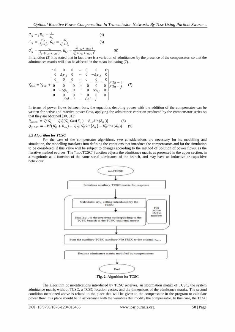
5.2 Algorithm for TCSC
For the case of the compensator algorithms, two considerations are necessary for its modelling and
simulation, the modelling translates into defining the variations that introduce the compensators and for the simulation
to be considered, if this value will be subject to changes according to the method of Solution of power flows, as the
iterative method evolves. The "modTCSC" function adjusts the admittance matrix as presented in the upper section, in
a magnitude as a function of the same serial admittance of the branch, and may have an inductive or capacitive
behaviour.
Fig. 2. Algorithm for TCSC
The algorithm of modifications introduced by TCSC receives, an information matrix of TCSC, the system
admittance matrix without TCSC, a TCSC location vector, and the dimensions of the admittance matrix. The second
condition mentioned above is related to the place that will be given to the compensator in the program to calculate
power flow, this place should be in accordance with the variables that modify the compensator. In this case, the TCSC

Optimal Reactive Power Compensation In Transmission Networks By Tcsc Using Particle Swarm ..
DOI: 10.9790/1676-1204015466 www.iosrjournals.org 59 | Page
changes the serial admittance of a branch of the system, so its location must go after the admittance matrix is
computed without compensators and it does not depend of any parameter that changes during the iterations as the
voltage, it is not necessary to place it within the loop of the iterative method.
In order to avoid that the "modTCSC" function is called without active TCSC, a conditional is placed that
allows to start the function only on the test of active compensators, this conditional is used for the three types of
compensators treated in this document and use a column to State of operation in each compensator that marks with
one the operation and with zero the non-operation of a compensator in an extension or bar.
VI. Formulation of The Problem
Power losses, low power factor and degradation of the voltage profile are the result of strong current flow in
power systems. These phenomena are more pronounced in distribution networks where the branch currents are
stronger compared to those circulating in the transport networks. This state has paid great attention to the distribution
networks and the strong currents circulating there in order to limit their intensities and thus improve the quality of
energy supplied to consumers. The limitation cannot be done, if the network is not reconfigured, by acting on the
reactive components of the branch currents then, the most indicated means is the installation of batteries of shunts
capacitors. The installation of capacitor banks must be done rationally, i.e. in such a way that the quality of the energy
is improved without, however, making major investments which would increase the energy consumption. The
problem is therefore to decide the number of batteries, their powers and their locations which would make an
objective function "F" maximum. This objective therefore makes the problem of reactive energy compensation an
optimization problem. However, owed to the discrete nature of the battery sizes and their locations, this problem is
non-linear with constraints. It is generally modelled as follows:
max 𝑓(𝑥, 𝑢) 𝑠𝑢𝑏𝑗𝑒𝑐𝑡 𝑡𝑜:𝑥𝑚𝑖𝑛 ≤ 𝑥 ≤ 𝑥𝑚𝑎𝑥
𝑢𝑚𝑖𝑛 ≤ 𝑢 ≤ 𝑢𝑚𝑎𝑥
𝑔(𝑥) ≥ 0
(10)
Where,
𝑓: is the objective function to maximize.
𝑔: is the equality constraint. It is the set of equations of the power flow
𝑥: is the control variable vector
𝑢: is the state variable vector.
6.1 Objective Function
The choice of the objective function is dictated by the concern to take into account at the same time the economic
aspect and the electrical aspect of the problem. The objective function on which all the authors who have dealt with
the problem of optimization of reactive energy compensation is the so-called "economic return" function or cost
reduction noted as "∆S". Mathematical expression is given by:
∆𝑆 = 𝑘𝑝∆𝑃 − 𝐾𝑐𝑖𝑄𝑐𝑖𝑛𝑐𝑖=1 (11)
Where,
𝑛𝑐: is the total number of batteries installed.
𝑘𝑝 : is the cost of kW produced (₹/kW).
𝐾𝑐𝑖 : is the annual price of kVAr installed depreciation and life included.
𝑄𝑐𝑖 : is the size of the installed battery at node "𝑘".
∆𝑃: is the reduction of the active power losses.
6.2 Reduction of Active Power Losses
The reduction of the power losses due to a battery "k" is equal to the difference of the losses of active power in the
network before and after the installation of the said capacitor bank. It is given by:
∆𝑃𝑘 = 𝑃𝑎𝑣𝑘− 𝑃𝑎𝑝𝑘
(12)
Where,
𝑃𝑎𝑣𝑘: are the active power losses in line before compensation.
𝑃𝑎𝑝𝑘: are active power losses in line after compensation.
6.3 Reduction of Reactive Power Losses
The reduction of the reactive power losses due to a battery installed at node "𝑘" of the distribution line is defined by
the difference between the losses before and after the installation of batteries in question of capacitors. It is given by:
∆𝑄𝑘 = 𝑄𝑎𝑣𝑘− 𝑄𝑎𝑝𝑘
(13)
Where,
𝑄𝑎𝑣𝑘: are the losses of reactive power in line before compensation.
𝑄𝑎𝑝𝑘: are the losses of reactive power in line after compensation.
6.4 Reactive Power Losses
The losses of reactive power in a distribution network line composed of n branches are given by the following
formula:
𝑄𝑎𝑣𝑘= 𝑥𝑖𝐼𝑖
2𝑛𝑖=1 (14)

Optimal Reactive Power Compensation In Transmission Networks By Tcsc Using Particle Swarm ..
DOI: 10.9790/1676-1204015466 www.iosrjournals.org 60 | Page
Where,
𝑥 is the reactance of branch 𝑖 𝐼𝑖 is the line current of the 𝑖𝑡 branch.
As with the active power losses, the active and reactive components of the branch current thus allow to write the
losses of reactive power as follows:
𝑄𝑎𝑣𝑘= 𝑥𝑖𝐼𝑎𝑖
2𝑛𝑖=1 + 𝑥𝑖𝐼𝑟𝑖
2𝑛𝑖=1 (15)
The losses of reactive power when a capacitor bank is placed on a node 𝑘 are given by:
𝑄𝑎𝑝𝑘= 𝑥𝑖𝐼𝑎𝑖
2𝑛𝑖=1 + 𝑥𝑖 𝐼𝑟𝑖 − 𝐼𝑐𝑟𝑘 2𝑘
𝑖=1 + 𝑥𝑖𝐼𝑟𝑖2𝑛
𝑖=𝑘+1 (16)
The reduction of reactive power losses by calculating the difference between equation (15) and equation (16), will be
equal to:
∆𝑄𝑘 = 2𝐼𝑐𝑟𝑘 𝑥𝑖𝐼𝑟𝑖 − 𝐼𝑐𝑟𝑘2𝑘
𝑖=1 𝑥𝑖𝑘𝑖=1 (17)
6.5 Heuristic Method
Heuristic methods are based on experience and practice. They are easy to understand and simple in their
implementation. They use sensitivity factors which they incorporate into optimization methods in order to achieve
qualitative solutions with small computational efforts. The heuristic methods were first introduced by Civanlar et al.
[32] and Taylor et al. [33] to reduce the power losses in the distribution networks by reconfiguration of the latter.
Because of the simplicity of the method. Abdel-Salam et al. [34] took up the idea and developed a heuristic method to
determine the sensitive nodes where the capacitor banks will be placed. The latter are decided by first finding the
branches where the most power losses occur as a result of the reactive charge currents. The node whose reactive load
current produces the most reduction in power losses in the branch in question is said to be the most sensitive. Chis et
al. [36] have enhanced the reference method [35] by considering that the most sensitive node is the one whose reactive
load current produces the most reduction in power losses of the entire network studied. In both of these last two
references the objective function considered is the net economic savings function except that in the case of Chis [36],
different load levels were considered. Haque [37] in the method he proposed was aimed at minimizing power losses.
The candidate nodes for receiving the capacitor banks are identified by installing at each of the nodes of the network
taken alone a capacitor bank which minimizes power losses. Once the candidate nodes are determined, the optimum
powers of the batteries to be placed there are determined simultaneously in order to avoid overcompensation.
Nevertheless, the author considered the powers of the batteries as continuous variables which does not answer the
reality of the problem. Mekhamer et al. [38] proposed two heuristic methods to solve the problem of optimization of
reactive energy compensation. In the first method which they proposed and all in [37], the sensitive nodes are
identified by installing, at each node of the network taken alone, a battery of capacitors which maximizes the
reduction of the cost. The most sensitive node is the one that gives the greatest cost reduction. It is therefore selected
first to receive the standard battery closest to the optimal battery which maximizes the cost reduction. The second
method proposed by the authors is identical to the first one except that in order to select the candidate nodes and to
calculate the optimal sizes of the batteries, they consider the reduction of the power losses instead of the reduction of
the cost. Hamouda et al. [39] gave a method in which the candidate nodes for receiving the capacitor banks are
determined as a function of the effect of the reactive current of the load at each node on the power losses of the whole
Network studied. These nodes are ranked in decreasing order according to the effects on power losses. The range node
1 is selected first to obtain a standard size battery, just smaller or just larger than the optimum size battery, depending
on the reduction it produces
Since the problem of determining the suitable battery locations has been separated from that of optimum power
determination since the locations are determined by the sensitivity factors then the size calculation is generally
modeled as follows:
max ∆𝑆𝑘(𝑄𝑐𝑘 ) 𝑠𝑢𝑏𝑗𝑒𝑐𝑡 𝑡𝑜:
𝑔 𝑄𝑐𝑘 = 0𝑄𝑐𝑚𝑖𝑛
≤ 𝑄𝑐𝑘 ≤ 𝑄𝑐𝑚𝑎𝑥
𝑉𝑚𝑖𝑛 ≤ 𝑉𝑖 ≤ 𝑉𝑚𝑎𝑥
(18)
6.6 New Modeling of the Problem
As stressed by Hamouda et al. [39], the stress imposed on the voltage may not be satisfied if small voltage limits are
considered and therefore the problem would be unresolved. Such as the placement of shunted capacitors on a
distribution network, where the effect is to increase the voltage which would at most exceed the maximum permissible
value. In this case, the network (or branch) is said to be overcompensated and thus the reactive component (𝐼𝑟𝑖 ) of the
branch current becomes positive. To avoid overcompensation, this component of the current d must always be
negative or equal to zero.
By substituting the constraint on the tension with that made on the branch current, the new mathematical model of the
problem becomes:
max ∆𝑆𝑘(𝑄𝑐𝑘 ) 𝑠𝑢𝑏𝑗𝑒𝑐𝑡 𝑡𝑜:
𝑔 𝑄𝑐𝑘 = 0𝑄𝑐𝑚𝑖 𝑛
≤ 𝑄𝑐𝑘 ≤ 𝑄𝑐𝑚𝑎𝑥
𝐼𝑟𝑖 ≤ 0 𝑖 = 1, , , 𝑛𝑗
(19)
Optimal Reactive Power Compensation In Transmission Networks By Tcsc Using Particle Swarm ..
DOI: 10.9790/1676-1204015466 www.iosrjournals.org 61 | Page
6.7 Optimal Operation of Batteries
The sensitivity of the reduction of the active power losses of the line to each of the reactive components of the charge
currents is used to determine the optimum battery locations [38]. This reduction in power losses for a given node "k"
is defined as the difference between the power losses before canceling the reactive current of the load at node "𝑘" and
after the latter has been canceled. It is given by:
∆𝑃𝑘 = 𝑃𝑘𝑎𝑣 − 𝑃𝑘
𝑎𝑝 (20)
The power losses before the cancellation of the reactive current of the load at the node "𝑘" are given by:
𝑃𝑘𝑎𝑣 = 𝑟𝑖𝐼𝑎𝑖
2𝑛𝑖=1 + 𝑟𝑖𝐼𝑟𝑖
2𝑛𝑖=1 (21)
The power losses after the cancellation of the reactive current of the load at the node "𝑘" are given by:
𝑃𝑘𝑎𝑝
= 𝑟𝑖𝐼𝑎𝑖2𝑛
𝑖=1 + 𝑟𝑖 𝐼𝑟𝑖 − 𝐼𝐿𝑟𝑘 2𝑘𝑖=1𝑖∈𝑆𝑘
+ 𝑟𝑖𝐼𝑟𝑖2𝑛
𝑖=𝑘+1 (22)
After simplification, the reduction in power losses will have the following expression:
∆𝑃𝑘 = 2𝐼𝐿𝑟𝑘 𝑟𝑖𝐼𝑟𝑖 − 𝐼𝐿𝑟𝑘2𝑘
𝑖=1𝑖∈𝑆𝑘
𝑟𝑖𝑘𝑖=1𝑖∈𝑆𝑘
(23)
The most sensitive node is one whose reactive charge current produces the greatest reduction in losses. It will then
have range 1 and will be considered first to receive a capacitor battery of optimal size.
6.8 Determination of Optimal Sizes
To calculate the optimum sizes of the batteries, the currents they generate are first determined. This current is
calculated so as to make the objective function the maximum ∆𝑆𝑘 cost reduction. This current is acquired by
undertaking the accompanying condition: 𝜕∆𝑆
𝜕𝐼𝑐𝑟𝑘= 0 (24)
The expression of the current is then given by:
𝐼𝑐𝑟𝑘 =
2𝑘𝑝 𝑟𝑖𝐼𝑟𝑖𝑘𝑖=1𝑖∈𝑆𝑘
+2𝑘𝑐𝑚 𝑥𝑖𝐼𝑟𝑖𝑘𝑖=1𝑖∈𝑆𝑘
−𝑘𝑐𝑘 𝑉𝑐𝑘
2𝑘𝑝 𝑟𝑖𝑘𝑖=1𝑖∈𝑆𝑘
+2𝑘𝑐𝑚 𝑥𝑖𝑘𝑖=1𝑖∈𝑆𝑘
(25)
The initial optimum power is calculated by the following expression:
𝑄𝑐𝑘 = 𝑉𝑐𝑘 𝐼𝑐𝑟𝑘 (26)
The maximum value of the cost reduction in this case:
∆𝑆𝑘𝑚𝑎𝑥=
2𝑘𝑝 𝑟𝑖𝐼𝑟𝑖𝑘𝑖=1 +2𝑘𝑐𝑚 𝑥𝑖𝐼𝑟𝑖−𝑘𝑐𝑘 𝑄𝑐𝑘
𝑘𝑖=1
2
4 𝑘𝑝 𝑟𝑖𝑘𝑖=1 +𝑘𝑐𝑚 𝑥𝑖
𝑘𝑖=1
(27)
The value of the equivalent power loss reduction is given by:
∆𝑃∆𝑆𝑚𝑎𝑥=
4𝑘𝑝2 𝑟𝑖
𝑘𝑖=1 𝐼𝑖
2 + 4𝑘𝑐𝑚 𝑥𝑖𝑘𝑖=1 𝐼𝑖
2 − 𝑘𝑐𝑘𝑉𝑐𝑘 2
2𝑘𝑝 𝑘𝑝 𝑟𝑖𝑘𝑖=1 + 𝑘𝑐𝑚 𝑥𝑖
𝑘𝑖=1
−𝑘𝑐𝑚 𝑥𝑖 2𝑘𝑝 𝑟𝑖
𝑘𝑖=1 𝐼𝑖 + 2𝑘𝑐𝑚 𝑥𝑖
𝑘𝑖=1 𝐼𝑖 − 𝑘𝑐𝑘𝑉𝑐𝑘
2𝑘𝑖=1
4 𝑘𝑝 𝑟𝑖𝑘𝑖=1 + 𝑘𝑐𝑚 𝑥𝑖
𝑘𝑖=1
2
(28)
VII. Load Flow Analysis Using Newton-Raphson Method This method requires more time per iteration where it does not requires only a few iterations even for large networks.
However, it requires storage as well as significant computing power. Let us assume:
𝑆𝑖 = 𝐼𝑖∗𝑉𝑖 (29)
𝐼𝑖∗ = 𝑌𝑖𝑚
∗𝑉𝑚∗𝑛
𝑚=1 (30)
𝑌𝑖𝑚 = 𝜌𝑖𝑚 + 𝑗𝛽𝑖𝑚 (31)
Because of the quadratic convergence of the Newton-Raphson method, a solution of accuracy can be achieved in just
a few iterations. These characteristics make the success of the Fast Decoupled Load Flow and the Newton-Raphson.
7.1 Fast Decoupled Load Flow (FDL)
The variation of the active power is less sensitive to the variation of the voltage V, on the other hand, it is more
sensitive to that of phase 𝛿. On the other hand, the variation of the reactive power is more sensitive to the variation of
the voltage V, and is less sensitive to that of phase𝛿. The elements of JACOBIEN 𝐽𝑃𝑉 are calculated: 𝜕𝑃𝑖
𝜕 𝑉𝑗 = 𝑉𝑖 . 𝑌𝑖𝑗 . cos(𝜃𝑖𝑗 − 𝛿𝑖 + 𝛿𝑗 ) (32)
Where, 𝜃𝑖𝑗 ≈ 90° 𝑎𝑛𝑑 𝛿𝑖 ≈ 𝛿𝑗 then 𝜕𝑃𝑖
𝜕 𝑉𝑗 ≈ 𝑉𝑖 . 𝑌𝑖𝑗 . cos(90°)=0.0
Now, we calculate the elements of JACOBIEN𝐽𝑄𝛿 : 𝜕𝑄𝑖
𝜕 𝛿𝑗 = − 𝑉𝑖 . 𝑉𝑗 . 𝑌𝑖𝑗 . cos(𝜃𝑖𝑗 − 𝛿𝑖 + 𝛿𝑗 ) (33)
Where, 𝜃𝑖𝑗 ≈ 90° 𝑎𝑛𝑑 𝛿𝑖 ≈ 𝛿𝑗 then 𝜕𝑄𝑖
𝜕 𝛿𝑗 ≈ − 𝑉𝑖 . 𝑉𝑗 . 𝑌𝑖𝑗 . cos 90° = 0.0

Optimal Reactive Power Compensation In Transmission Networks By Tcsc Using Particle Swarm ..
DOI: 10.9790/1676-1204015466 www.iosrjournals.org 62 | Page
Consequently, the sub-matrices of the JACOBIEN 𝐽𝑄𝛿 and 𝐽𝑃𝑉 are null.
Δ𝑃Δ𝑄
= 𝐽𝑃𝛾
0
0𝐽𝑄𝑉
. Δ𝛿Δ𝑉
⟹Δ𝑃 = 𝐽𝑃𝛿 . Δ𝛿 =
𝜕𝑃
𝜕𝛿. Δ𝛿
Δ𝑄 = 𝐽𝑄𝑉 . Δ 𝑉 =𝜕𝑄
𝜕 𝑉 . Δ 𝑉
(34)
The elements of JACOBIEN 𝐽𝑃𝛿 are calculated: 𝜕𝑃𝑖
𝜕𝛿𝑖=? (35)
𝜕𝑃𝑖
𝜕𝛿𝑖
= 𝑉𝑖 . 𝑉𝑗 . 𝑌𝑖𝑗 . sin(𝜃𝑖𝑗 − 𝛿𝑖 + 𝛿𝑗 )
𝑁
𝑗=𝑗≠𝑖
= − 𝑉𝑖 2. 𝑌𝑖𝑖 . sin 𝜃𝑖𝑖 + 𝑉𝑖 . 𝑉𝑗 . 𝑌𝑖𝑗 . sin(𝜃𝑖𝑗 − 𝛿𝑖 + 𝛿𝑗 )𝑁
𝑗=𝑗≠𝑖
(36)
Where, 𝜕𝑃𝑖
𝜕𝛿𝑖= − 𝑉𝑖
2. 𝑌𝑖𝑖 . sin 𝜃𝑖𝑖 − 𝑄𝑖 (37)
And
𝑄𝑖 = 𝑉𝑖 . 𝑉𝑗 . 𝑌𝑖𝑗 . sin(𝜃𝑖𝑗 − 𝛿𝑖 + 𝛿𝑗 )𝑁𝑗 = (38)
𝑌𝑖𝑖 . sin 𝜃𝑖𝑖 = 𝐵𝑖𝑖 , 𝐵𝑖𝑖 ≫ 𝑄𝐼𝜕𝑃𝑖
𝜕𝛿𝑖= − 𝑉𝑖
2. 𝐵𝑖𝑖 and 𝑉𝑖 2 = 𝑉𝑖 so
𝜕𝑃𝑖
𝜕𝛿𝑖= − 𝑉𝑖 . 𝐵𝑖𝑖
Now we calculate𝜕𝑃𝑖
𝜕𝛿𝑗=?
𝜕𝑃𝑖
𝜕𝛿𝑗= − 𝑉𝑖 . 𝑉𝑗 . 𝑌𝑖𝑗 . sin(𝜃𝑖𝑗 − 𝛿𝑖 + 𝛿𝑗 ) (39)
Since 𝛿𝑗 − 𝛿𝑖 ≈ 0, therefore, 𝜕𝑃𝑖
𝜕𝛿𝑗= − 𝑉𝑖 . 𝑉𝑗 . 𝑌𝑖𝑗 . sin(𝜃𝑖𝑗 ) (40)
Where, 𝑌𝑖𝑗 . sin 𝜃𝑖𝑗 = 𝐵𝑖𝑗 , 𝑉𝑗 ≈ 1 𝜕𝑃𝑖
𝜕𝛿𝑗= − 𝑉𝑗 . 𝐵𝑖𝑗 (41)
The elements of Jacobien 𝐽𝑄𝑉are calculated: 𝜕𝑄𝑖
𝜕𝑉𝑗=? (42)
𝜕𝑄𝑖
𝜕 𝑉𝑖 = −2. 𝑉𝑖 . 𝑌𝑖𝑖 . sin 𝜃𝑖𝑖 − 𝑉𝑗 . 𝑌𝑖𝑗 . sin(𝜃𝑖𝑗 − 𝛿𝑖 + 𝛿𝑗 )𝑛
𝑗=1𝑗≠𝑖
(43)
𝜕𝑄𝑖
𝜕 𝑉𝑖 = − 𝑉𝑖 . 𝑌𝑖𝑗 . sin 𝜃𝑖𝑖 − 𝑉𝑖
−1 𝑉𝑖 . 𝑉𝑗 . 𝑌𝑖𝑗 . sin(𝜃𝑖𝑗 − 𝛿𝑖 + 𝛿𝑗 )𝑛𝑗=1 (44)
𝜕𝑄𝑖
𝜕 𝑉𝑖 = − 𝑉𝑖 . 𝑌𝑖𝑖 . sin 𝜃𝑖𝑖 − 𝑉𝑖
−1 . 𝑄𝑖 (45)
Where 𝑄𝑖 = − 𝑉𝑖 . 𝑉𝑗 . 𝑌𝑖𝑗 . sin(𝜃𝑖𝑗 − 𝛿𝑖 + 𝛿𝑗 )𝑛𝑗 =1
𝑌𝑖𝑖 . sin 𝜃𝑖𝑖 = 𝐵𝑖𝑖 , 𝐵𝑖𝑖 ≫ 𝑄 ⟹𝜕𝑄𝑖
𝜕 𝑉𝑖 = − 𝑉𝑖 . 𝐵𝑖𝑖
And 𝜕𝑄𝑖
𝜕 𝑉𝑗 =?
𝜕𝑄𝑖
𝜕 𝑉𝑗 = − 𝑉𝑖 . 𝑌𝑖𝑖 . sin(𝜃𝑖𝑗 − 𝛿𝑖 + 𝛿𝑗 ) (46)
Since 𝛿𝑗 − 𝛿𝑖 ≈ 0, therefore, 𝜕𝑄𝑖
𝜕 𝑉𝑗 = − 𝑉𝑖 . 𝑌𝑖𝑖 . sin(𝜃𝑖𝑗 ) (47)
Where, 𝑌𝑖𝑖 . sin(𝜃𝑖𝑗 ) = Bii ,𝜕𝑄𝑖
𝜕 𝑉𝑗 = − 𝑉𝑖 . 𝐵𝑖𝑖
The individual power change equations in 𝐽𝑃𝛿 and 𝐽𝑄𝑉 are:
Δ𝑃𝑖 = − 𝑉𝑖 . 𝐵𝑖𝑗 . Δ𝛿𝑗𝑁𝐽=1 ⟹
Δ𝑃𝑖
𝑉𝑖 = −𝐵𝑖𝑗 . Δ𝛿𝑗
𝑁𝐽=1 (48)
Δ𝑄𝑖 = − 𝑉𝑖 . 𝐵𝑖𝑗 . Δ 𝑉𝑗 𝑁𝐽=1 ⟹
Δ𝑄𝑖
𝑉𝑖 = −𝐵𝑖𝑗 . Δ 𝑉𝑗
𝑁𝐽=1 (49)
Δ𝑃
𝑉𝑖 = −𝐵′. Δ𝛿 ⟹ Δ𝛿 = −[𝐵′] −1.
Δ𝑃
𝑉𝑖 (50)
Δ𝑄𝑖
𝑉𝑖 = −𝐵′′. Δ 𝑉 ⟹ Δ 𝑉 = −[𝐵′′] −1 .
Δ𝑄𝑖
𝑉𝑖 (51)
The fast decoupled method FDL performs the same execution times as that of Newton-Raphson for very small
networks. However, it becomes faster for more and the usual tolerances.
VIII. Optimal Location Using Particle Swarm Optimization (PSO) In the proposed system, the location of TCSC in a particular bus system is decided by PSO algorithms. The
objective function is minimized using the abovementioned technique. James Kennedy and Russell C. Eberhart

Optimal Reactive Power Compensation In Transmission Networks By Tcsc Using Particle Swarm ..
DOI: 10.9790/1676-1204015466 www.iosrjournals.org 63 | Page
proposed a PSO approach in 1995. This approach is a heuristic method [40]. The evaluation of candidate solution of
current search space is done on the basis of iteration process (as shown in Fig. 3). The minima and maxima of
objective function is determined by the candidate’s solution as it fits the task’s requirements. Since PSO algorithm do
not accept the objective function data as its inputs, therefore the solution is randomly away from minimum and
maximum (locally/ globally) and also unknown to the user. The speed and position of candidate’s solution is
maintained and at each level, fitness value is also updated. The best value of fitness is recorded by PSO for an
individual record. The other individuals reaching this value are taken as the individual best position and solution for
given problem. The individuals reaching this value are known as global best candidate solution with global best
position. The up gradation of global and individual best fitness value is carried out and if there is a requirement then
global and local best fitness values are even replaced. For PSO’s optimization capability, the updation of speed and
position is necessary. Each particle’s velocity is simplified with the help of subsequent formula:
𝑣𝑖 𝑡 + 1 = 𝑤𝑣𝑖 𝑡 + 𝑐1𝑟1 𝑥 𝑖 𝑡 − 𝑥𝑖 𝑡 + 𝑐2𝑟2 𝑔 𝑡 − 𝑥𝑖 𝑡 (52)
Fig. 3. Flow chart of PSO algorithm [40]
IX. Results Analysis
Load Flow Analysis Using Newton Raphson
Fig. 4. PSO iteration graph
Fig. 5. Active & Reactive power losses in IEEE-14 bus system using PSO
10 20 30 40 50 60 70 80 90 100112
114
116
118
120
122
124
Iteration Number
Glo
bal B
est
Particle Swarm optimization
NRPF NRPF with TCSC (PSO)0
10
20
30
40
50
60
Pow
er
Loss (
MW
& M
Var)
Active & Reactive Power Losses in IEEE Bus System
13.7214
56.5404
13.0825
46.6376
P
Q

Optimal Reactive Power Compensation In Transmission Networks By Tcsc Using Particle Swarm ..
DOI: 10.9790/1676-1204015466 www.iosrjournals.org 64 | Page
Load Flow Analysis Using Newton Raphson with TCSC at optimal location
Fig. 6. PSO iteration graph
Fig. 7. Active & Reactive power losses in IEEE-14 bus system with PSO
Load Flow Analysis Using Newton Raphson
Fig. 8. PSO iteration graph
Fig. 9. Active & Reactive power losses in IEEE-30 bus system using PSO
10 20 30 40 50 60 70 80 90 100100
110
120
130
140
150
160
Iteration Number
Glo
bal B
est
Particle Swarm optimization
NRPF NRPF with TCSC (PSO)0
1
2
3
4
5
6
7x 10
7
Pow
er L
oss
(MW
& M
Var
)
Active & Reactive Power Losses in IEEE Bus System
17.8162 69.4087
20466840.317
63489831.283P
Q
10 20 30 40 50 60 70 80 90 100160
165
170
175
Iteration Number
Glo
bal B
est
Particle Swarm optimization
NRPF NRPF with TCSC (PSO)0
10
20
30
40
50
60
70
80
90
Pow
er L
oss
(MW
& M
Var
)
Active & Reactive Power Losses in IEEE Bus System
19.0564
87.4032
19.7963
62.8041
P
Q
Optimal Reactive Power Compensation In Transmission Networks By Tcsc Using Particle Swarm ..
DOI: 10.9790/1676-1204015466 www.iosrjournals.org 65 | Page
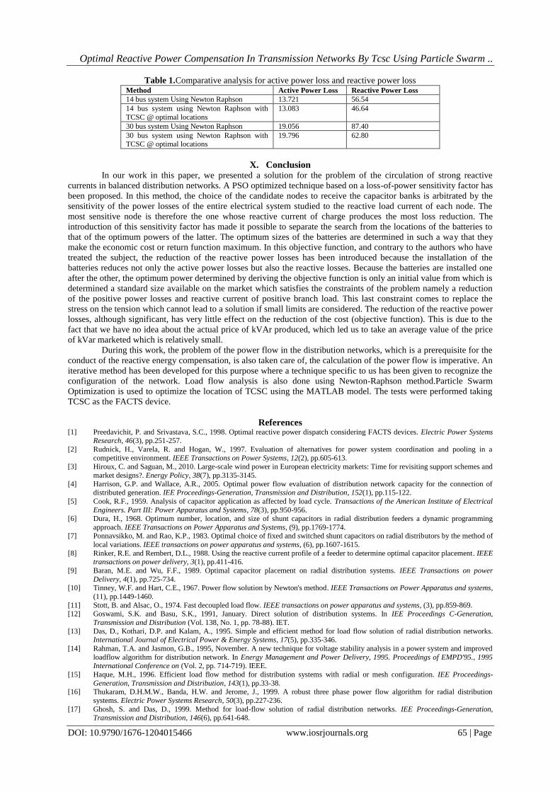
Table 1.Comparative analysis for active power loss and reactive power loss Method Active Power Loss Reactive Power Loss
14 bus system Using Newton Raphson 13.721 56.54
14 bus system using Newton Raphson with
TCSC @ optimal locations
13.083 46.64
30 bus system Using Newton Raphson 19.056 87.40
30 bus system using Newton Raphson with TCSC @ optimal locations
19.796 62.80
X. Conclusion In our work in this paper, we presented a solution for the problem of the circulation of strong reactive
currents in balanced distribution networks. A PSO optimized technique based on a loss-of-power sensitivity factor has
been proposed. In this method, the choice of the candidate nodes to receive the capacitor banks is arbitrated by the
sensitivity of the power losses of the entire electrical system studied to the reactive load current of each node. The
most sensitive node is therefore the one whose reactive current of charge produces the most loss reduction. The
introduction of this sensitivity factor has made it possible to separate the search from the locations of the batteries to
that of the optimum powers of the latter. The optimum sizes of the batteries are determined in such a way that they
make the economic cost or return function maximum. In this objective function, and contrary to the authors who have
treated the subject, the reduction of the reactive power losses has been introduced because the installation of the
batteries reduces not only the active power losses but also the reactive losses. Because the batteries are installed one
after the other, the optimum power determined by deriving the objective function is only an initial value from which is
determined a standard size available on the market which satisfies the constraints of the problem namely a reduction
of the positive power losses and reactive current of positive branch load. This last constraint comes to replace the
stress on the tension which cannot lead to a solution if small limits are considered. The reduction of the reactive power
losses, although significant, has very little effect on the reduction of the cost (objective function). This is due to the
fact that we have no idea about the actual price of kVAr produced, which led us to take an average value of the price
of kVar marketed which is relatively small.
During this work, the problem of the power flow in the distribution networks, which is a prerequisite for the
conduct of the reactive energy compensation, is also taken care of, the calculation of the power flow is imperative. An
iterative method has been developed for this purpose where a technique specific to us has been given to recognize the
configuration of the network. Load flow analysis is also done using Newton-Raphson method.Particle Swarm
Optimization is used to optimize the location of TCSC using the MATLAB model. The tests were performed taking
TCSC as the FACTS device.
References [1] Preedavichit, P. and Srivastava, S.C., 1998. Optimal reactive power dispatch considering FACTS devices. Electric Power Systems
Research, 46(3), pp.251-257.
[2] Rudnick, H., Varela, R. and Hogan, W., 1997. Evaluation of alternatives for power system coordination and pooling in a
competitive environment. IEEE Transactions on Power Systems, 12(2), pp.605-613. [3] Hiroux, C. and Saguan, M., 2010. Large-scale wind power in European electricity markets: Time for revisiting support schemes and
market designs?. Energy Policy, 38(7), pp.3135-3145.
[4] Harrison, G.P. and Wallace, A.R., 2005. Optimal power flow evaluation of distribution network capacity for the connection of distributed generation. IEE Proceedings-Generation, Transmission and Distribution, 152(1), pp.115-122.
[5] Cook, R.F., 1959. Analysis of capacitor application as affected by load cycle. Transactions of the American Institute of Electrical
Engineers. Part III: Power Apparatus and Systems, 78(3), pp.950-956.
[6] Dura, H., 1968. Optimum number, location, and size of shunt capacitors in radial distribution feeders a dynamic programming
approach. IEEE Transactions on Power Apparatus and Systems, (9), pp.1769-1774. [7] Ponnavsikko, M. and Rao, K.P., 1983. Optimal choice of fixed and switched shunt capacitors on radial distributors by the method of
local variations. IEEE transactions on power apparatus and systems, (6), pp.1607-1615.
[8] Rinker, R.E. and Rembert, D.L., 1988. Using the reactive current profile of a feeder to determine optimal capacitor placement. IEEE transactions on power delivery, 3(1), pp.411-416.
[9] Baran, M.E. and Wu, F.F., 1989. Optimal capacitor placement on radial distribution systems. IEEE Transactions on power
Delivery, 4(1), pp.725-734. [10] Tinney, W.F. and Hart, C.E., 1967. Power flow solution by Newton's method. IEEE Transactions on Power Apparatus and systems,
(11), pp.1449-1460.
[11] Stott, B. and Alsac, O., 1974. Fast decoupled load flow. IEEE transactions on power apparatus and systems, (3), pp.859-869. [12] Goswami, S.K. and Basu, S.K., 1991, January. Direct solution of distribution systems. In IEE Proceedings C-Generation,
Transmission and Distribution (Vol. 138, No. 1, pp. 78-88). IET.
[13] Das, D., Kothari, D.P. and Kalam, A., 1995. Simple and efficient method for load flow solution of radial distribution networks. International Journal of Electrical Power & Energy Systems, 17(5), pp.335-346.
[14] Rahman, T.A. and Jasmon, G.B., 1995, November. A new technique for voltage stability analysis in a power system and improved
loadflow algorithm for distribution network. In Energy Management and Power Delivery, 1995. Proceedings of EMPD'95., 1995 International Conference on (Vol. 2, pp. 714-719). IEEE.
[15] Haque, M.H., 1996. Efficient load flow method for distribution systems with radial or mesh configuration. IEE Proceedings-
Generation, Transmission and Distribution, 143(1), pp.33-38. [16] Thukaram, D.H.M.W., Banda, H.W. and Jerome, J., 1999. A robust three phase power flow algorithm for radial distribution
systems. Electric Power Systems Research, 50(3), pp.227-236.
[17] Ghosh, S. and Das, D., 1999. Method for load-flow solution of radial distribution networks. IEE Proceedings-Generation, Transmission and Distribution, 146(6), pp.641-648.
Optimal Reactive Power Compensation In Transmission Networks By Tcsc Using Particle Swarm ..
DOI: 10.9790/1676-1204015466 www.iosrjournals.org 66 | Page
[18] Mok, S. Elangovan, Cao Longjian, Mma Salama, S., 2000. A new approach for power flow analysis of balanced radial distribution
systems. Electric Machines &Power Systems, 28(4), pp.325-340.
[19] Haque, M.H., 2000. A general load flow method for distribution systems. Electric Power Systems Research, 54(1), pp.47-54. [20] Aravindhababu, P., Ganapathy, S. and Nayar, K.R., 2001. A novel technique for the analysis of radial distribution systems.
International journal of electrical power & energy systems, 23(3), pp.167-171.
[21] Augugliaro, A., Dusonchet, L., Ippolito, M.G. and Sanseverino, E.R., 2001. An efficient iterative method for load-flow solution in radial distribution networks. In Power Tech Proceedings, 2001 IEEE Porto (Vol. 3, pp. 6-pp). IEEE.
[22] Mekhamer, S.F., Soliman, S.A., Moustafa, M.A. and El-Hawary, M.E., 2002. Load flow solution of radial distribution feeders: a
new contribution. International journal of electrical power & energy systems, 24(9), pp.701-707. [23] Baran, M.E. and Wu, F.F., 1989. Network reconfiguration in distribution systems for loss reduction and load balancing. IEEE
Transactions on Power delivery, 4(2), pp.1401-1407.
[24] Afsari, M., Singh, S.P., Raju, G.S. and Rao, G.K., 2002. A fast power flow solution of radial distribution networks. Electric Power Components and Systems, 30(10), pp.1065-1074.
[25] Ranjan, R. and DAS, 2003. Simple and efficient computer algorithm to solve radial distribution networks. Electric power
components and systems, 31(1), pp.95-107. [26] Ranjan, R., Venkatesh, B. and Das, D., 2002. A new algorithm for power distribution system planning. Electric Power Systems
Research, 62(1), pp.55-65.
[27] Hamouda, A. and Zehar, K., 2011. Improved algorithm for radial distribution networks load flow solution. International Journal of Electrical Power & Energy Systems, 33(3), pp.508-514.
[28] Lakdja, F. and Gherbi, F.Z., 2010. Impact of Thyristors Controlled Series Capacitor Devices and Optimal Power Flow on Power
Systems. Leonardo Journal of Sciences, 9(16), pp.145-157. [29] Tabatabaei, N.M., Aghajani, G., Boushehri, N.S. and Shoarinejad, S., 2011. Optimal location of FACTS devices using adaptive
particle swarm optimization mixed with simulated annealing. International Journal on Technical and Physical Problems of
Engineering (IJTPE), 7, pp.60-70. [30] Gitizadeh, M. and Kalantar, M., 2009. Optimum allocation of FACTS devices in Fars Regional Electric Network using genetic
algorithm based goal attainment. Journal of Zhejiang University-SCIENCE A, 10(4), pp.478-487.
[31] Ismail, M., Tawfik, G. and Hsen, H.A., 2012. Optimal location of multi type FACTS devices for multiple contingencies using genetic algorithms. International Journal of Energy Engineering, 2(2), pp.29-35.
[32] Civanlar, S., Grainger, J.J., Yin, H. and Lee, S.S.H., 1988. Distribution feeder reconfiguration for loss reduction. IEEE Transactions
on Power Delivery, 3(3), pp.1217-1223. [33] Taylor, T. and Lubkeman, D., 1990. Implementation of heuristic search strategies for distribution feeder reconfiguration. IEEE
Transactions on Power Delivery, 5(1), pp.239-246.
[34] Abdel-Salam, T.S., Chikhani, A.Y. and Hackam, R., 1994. A new technique for loss reduction using compensating capacitors
applied to distribution systems with varying load condition. IEEE Transactions on Power Delivery, 9(2), pp.819-827.
[35] Bala, J.L., Kuntz, P.A. and Taylor, R.M., 1995, October. Sensivity-based optimal capacitor placement on a radial distribution
feeder. In Northcon 95. i EEE Technical Applications Conference and Workshops Northcon95 (pp. 225-230). IEEE. [36] Chis, M., Salama, M.M.A. and Jayaram, S., 1997. Capacitor placement in distribution systems using heuristic search strategies. IEE
Proceedings-Generation, Transmission and Distribution, 144(3), pp.225-230. [37] Haque, M.H., 2000. Improvement of power delivery efficiency of distribution systems through loss reduction. In Power
Engineering Society Winter Meeting, 2000. IEEE (Vol. 4, pp. 2739-2744). IEEE.
[38] Mekhamer, S.F., El-Hawary, M.E., Soliman, S.A., Moustafa, M.A. and Mansour, M.M., 2002. New heuristic strategies for reactive power compensation of radial distribution feeders. IEEE Transactions on Power Delivery, 17(4), pp.1128-1135.
[39] Hamouda, A., Lakehal, N. and Zehar, K., 2010. Heuristic method for reactive energy management in distribution feeders. Energy
conversion and management, 51(3), pp.518-523. [40] Kennedy, J., 2011. Particle swarm optimization. In Encyclopedia of machine learning (pp. 760-766). Springer US.
IOSR Journal of Electrical and Electronics Engineering (IOSR-JEEE) is UGC approved
Journal with Sl. No. 4198, Journal no. 45125.
Subhash Shankar Zope Optimal Reactive Power Compensation in Transmission Networks By
TCSC Using Particle Swarm Optimization." IOSR Journal of Electrical and Electronics
Engineering (IOSR-JEEE) 12.4 (2017): 54-66.