Embed Size (px)
Citation preview
N8600936-092017
www.olympus-ims.com
Shinjuku Monolith, 2-3-1 Nishi-Shinjuku, Shinjuku-ku, Tokyo 163-0914, Japan
• All company and product names are registered trademarks and/or trademarks of their respective owners.• Images on the PC monitors are simulated.
• OLYMPUS CORPORATION is ISO14001 certified.• OLYMPUS CORPORATION is ISO9001 certified.• This product is designed for use in industrial environments for the EMC performance. Using it in a residential environment may affect other equipment in the environment.
• Specifications and appearances are subject to change without any notice or obligation on the part of the manufacturer. • Illumination devices for microscope have suggested lifetimes. Periodic inspections are required. Please visit our web site for details.
Advanced Microscopy Solutions for Metallurgy Inspection
Inverted Metallurgical Microscope
GX53
11
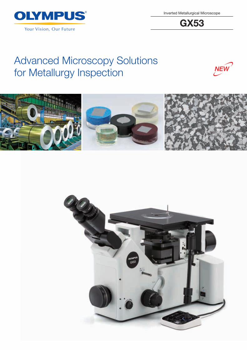
The GX53 inverted microscope is used for a wide range of applications often seen in the steel, automotive, electronics, and other manufacturing industries. The microscope enables users to inspect polished metals and cross-section samples simply by placing them upside down on the stage. The sample does not need to be leveled and can be thick, large, or heavy.The GX53 delivers crisp images that can be difficult to capture using conventional microscopy observation methods. When combined with OL
Quick analysis for large or thick sample materials
When combined with Pax-it™ 2 image analysis software, the microscope streamlines theinspection process from observation to image analysis and reporting.
22
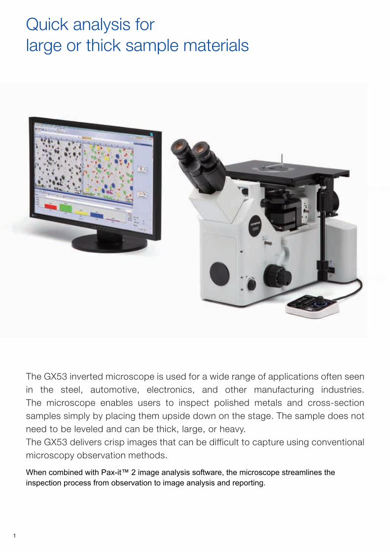
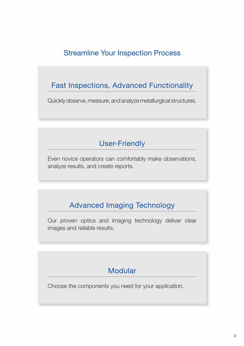
Quickly observe, measure, and analyze metallurgical structures.
Fast Inspections, Advanced Functionality
Streamline Your Inspection Process
Even novice operators can comfortably make observations, analyze results, and create reports.
User-Friendly
Our proven optics and imaging technology deliver clear images and reliable results.
Advanced Imaging Technology
Choose the components you need for your application.
Modular

3
Fast Inspections, Advanced Functionality
The GX53 microscope’s various observation capabilities provide clear, sharp images, so users can reliably detect defects in their samples.
The Invisible Becomes Visible: MIX TechnologyMIX technology produces unique observation images by combining darkfield with another observation method, such as brightfield or polarization. MIX observation enables users to view samples that are difficult to see with conventional microscopes, and represents even small height differences of sample surfaces. The circular LED illuminator used for darkfield observation has a directional darkfield function where one or more quadrants are illuminated at a given time. This reduces a sample’s halation and is useful for visualizing its surface texture.
Advanced Analysis Tools
Cross-section of a printed circuit board Stainless steel
MIX: Brightfield + Darkfield
DarkfieldQuardrant illumination of darkfield
Brightfield Brightfield
The substrate layers and through hole are invisible.
The texture is unobservable.
All the components are clearly represented. Both the material color and texture are visible.
The traces are invisible. The color information is eliminated.
MIX: Brightfield + Quardrant illumination of darkfield
7
User-Friendly
Maintain a comfortable posture
Convenient hand switch Easily control the stage during observation
Observe large, heavy samples Helps prevent objective collisions
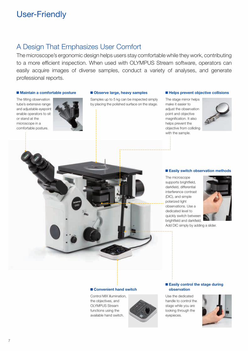
The tilting observation tube’s extensive range and adjustable eyepoint enable operators to sit or stand at the microscope in a comfortable posture.
Control MIX illumination, the objectives, and OLYMPUS Stream functions using the available hand switch.
Use the dedicated handle to control the stage while you are looking through the eyepieces.
Samples up to 5 kg can be inspected simply by placing the polished surface on the stage.
The stage mirror helps make it easier to adjust the observation point and objective magnification. It also helps prevent the objective from colliding with the sample.
Easily switch observation methods
The microscope supports brightfield, darkfield, differential interference contrast (DIC), and simple polarized light observations. Use a dedicated level to quickly switch between brightfield and darkfield. Add DIC simply by adding a slider.
The microscope’s ergonomic design helps users stay comfortable while they work, contributing to a more efficient inspection. When used with OLYMPUS Stream software, operators can easily acquire images of diverse samples, conduct a variety of analyses, and generate professional reports.
A Design That Emphasizes User Comfort
9
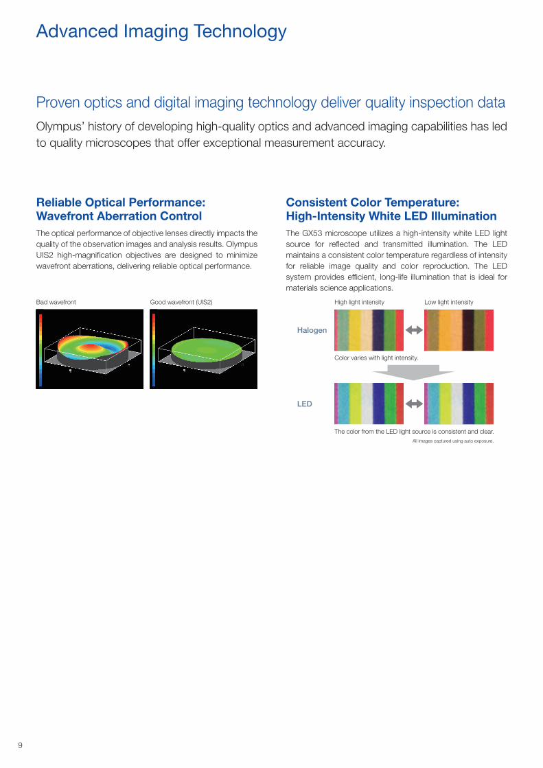
Bad wavefront
All images captured using auto exposure.
Good wavefront (UIS2) High light intensity Low light intensity
Halogen
LED
Color varies with light intensity.
The color from the LED light source is consistent and clear.
Reliable Optical Performance: Wavefront Aberration Control
Consistent Color Temperature: High-Intensity White LED Illumination
The optical performance of objective lenses directly impacts the quality of the observation images and analysis results. Olympus UIS2 high-magnification objectives are designed to minimize wavefront aberrations, delivering reliable optical performance.
The GX53 microscope utilizes a high-intensity white LED light source for reflected and transmitted illumination. The LED maintains a consistent color temperature regardless of intensity for reliable image quality and color reproduction. The LED system provides efficient, long-life illumination that is ideal for materials science applications.
Advanced Imaging Technology
Olympus’ history of developing high-quality optics and advanced imaging capabilities has led to quality microscopes that offer exceptional measurement accuracy.
Proven optics and digital imaging technology deliver quality inspection data
10
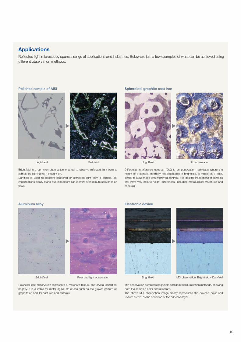
Brightfield is a common observation method to observe reflected light from a sample by illuminating it straight on.Darkfield is used to observe scattered or diffracted light from a sample, so imperfections clearly stand out. Inspectors can identify even minute scratches or flaws.
Polarized light observation represents a material’s texture and crystal condition brightly. It is suitable for metallurgical structures such as the growth pattern of graphite on nodular cast iron and minerals.
Differential interference contrast (DIC) is an observation technique where the height of a sample, normally not detectable in brightfield, is visible as a relief, similar to a 3D image with improved contrast. It is ideal for inspections of samples that have very minute height differences, including metallurgical structures and minerals.
MIX observation combines brightfield and darkfield illumination methods, showing both the sample’s color and structure.The above MIX observation image clearly reproduces the device’s color and texture as well as the condition of the adhesive layer.
Polished sample of AlSi
Aluminum alloy
Spheroidal graphite cast iron
Electronic device
Brightfield
Brightfield
Brightfield
Brightfield
Darkfield
Polarized light observation
DIC observation
MIX observation: Brightfield + Darkfield
ApplicationsReflected light microscopy spans a range of applications and industries. Below are just a few examples of what can be achieved using different observation methods.
11
Choose the Components You Need
Customizable
The GX53 microscope is designed to enable users to choose a variety of optical components to suit individual inspection and application requirements. The system can utilize all available observation methods. Users can also select from a variety of OLYMPUS Stream image analysis packages to meet image acquisition and analysis needs.
GX53 Reflected/Transmitted Light Combination
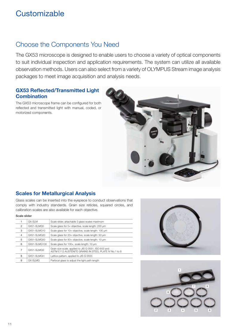
Scales for Metallurgical Analysis
The GX53 microscope frame can be configured for both reflected and transmitted light with manual, coded, or motorized components.
Glass scales can be inserted into the eyepiece to conduct observations that comply with industry standards. Grain size reticles, squared circles, and calibration scales are also available for each objective.
Scale slider
1 GX-SLM Scale slider, attachable 3 glass scales maximum
2 GX51-SLMG5 Scale glass for 5× objective, scale length: 200 μm
3 GX51-SLMG10 Scale glass for 10× objective, scale length: 100 μm
4 GX51-SLMG20 Scale glass for 20× objective, scale length: 50 μm
5 GX51-SLMG50 Scale glass for 50× objective, scale length: 10 μm
6 GX51-SLMG100 Scale glass for 100×, scale length: 10 μm
7 GX51-SLMGS Grain size scale, applied to JIS G 0551, ISO 643 and ASTM E112 AUSTENITE GRAINS IN STEEL PLATE IV No.1 to 8
8 GX51-SLMGH Lattice pattern, applied to JIS G 0555
9 GX-SLMG Parfocal glass to adjust the light path length
1
2 3 4
8
5
7
6
9
12
Microscope Frame
Light Sources
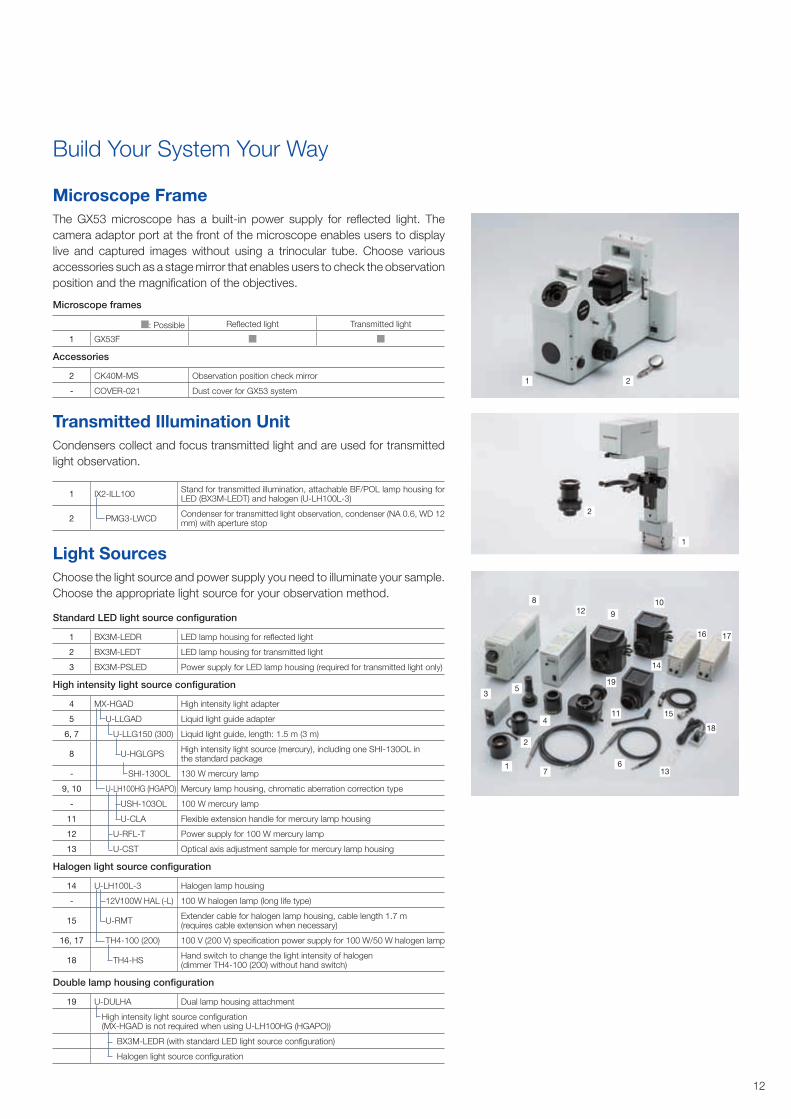
The GX53 microscope has a built-in power supply for reflected light. The camera adaptor port at the front of the microscope enables users to display live and captured images without using a trinocular tube. Choose various accessories such as a stage mirror that enables users to check the observation position and the magnification of the objectives.
Choose the light source and power supply you need to illuminate your sample. Choose the appropriate light source for your observation method.
Microscope frames
: Possible Reflected light Transmitted light
1 GX53F
Accessories
2 CK40M-MS Observation position check mirror
- COVER-021 Dust cover for GX53 system2
2
1
1
Standard LED light source configuration
1 BX3M-LEDR LED lamp housing for reflected light
2 BX3M-LEDT LED lamp housing for transmitted light
3 BX3M-PSLED Power supply for LED lamp housing (required for transmitted light only)
High intensity light source configuration
4 MX-HGAD High intensity light adapter
5 U-LLGAD Liquid light guide adapter
6, 7 U-LLG150 (300) Liquid light guide, length: 1.5 m (3 m)
8 U-HGLGPS High intensity light source (mercury), including one SHI-130OL in the standard package
- SHI-130OL 130 W mercury lamp
9, 10 U-LH100HG (HGAPO) Mercury lamp housing, chromatic aberration correction type
- USH-103OL 100 W mercury lamp
11 U-CLA Flexible extension handle for mercury lamp housing
12 U-RFL-T Power supply for 100 W mercury lamp
13 U-CST Optical axis adjustment sample for mercury lamp housing
Halogen light source configuration
14 U-LH100L-3 Halogen lamp housing
- 12V100W HAL (-L) 100 W halogen lamp (long life type)
15 U-RMT Extender cable for halogen lamp housing, cable length 1.7 m (requires cable extension when necessary)
16, 17 TH4-100 (200) 100 V (200 V) specification power supply for 100 W/50 W halogen lamp
18 TH4-HS Hand switch to change the light intensity of halogen (dimmer TH4-100 (200) without hand switch)
Double lamp housing configuration
19 U-DULHA Dual lamp housing attachment
High intensity light source configuration(MX-HGAD is not required when using U-LH100HG (HGAPO))
BX3M-LEDR (with standard LED light source configuration)
Halogen light source configuration
Transmitted Illumination UnitCondensers collect and focus transmitted light and are used for transmitted light observation.
1 IX2-ILL100 Stand for transmitted illumination, attachable BF/POL lamp housing for LED (BX3M-LEDT) and halogen (U-LH100L-3)
2 PMG3-LWCD Condenser for transmitted light observation, condenser (NA 0.6, WD 12 mm) with aperture stop
3
2
5
76
13
18
1511
14
19
4
1210
16
9
8
17
1
Build Your System Your Way
13
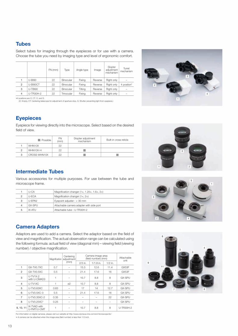
Camera AdaptersAdaptors are used to add a camera. Select the adaptor based on the field of view and magnification. The actual observation range can be calculated using the following formula: actual field of view (diagonal mm) – viewing field (viewing number) / objective magnification.
For information on digital cameras, please visit our website at http://www.olympus-ims.com/en/microscope/dc/
A camera can be attached when the image area (field number) is less than 1/3 inch.
MagnificationCentering
adjustment (mm)
Camera image area(field number) (mm) Attachable
unit2/3 in. 1/1.8 in. 1/2 in.
1 GX-TV0.7XC 0.7 – 15.3 12.6 11.4 GX53F
2 GX-TV0.5XC 0.5 – 21.4 17.6 16 GX53F
3 U-TV1X-2 with U-CMAD3 1 – 10.7 8.8 8 GX-SPU
4 U-TV1XC 1 ø2 10.7 8.8 8 GX-SPU
5 U-TV0.63XC 0.63 – 17 14 12.7 GX-SPU
6 U-TV0.5XC-3 0.5 – 21.4 17.6 16 GX-SPU
7 U-TV0.35XC-2 0.35 – – – 22 GX-SPU
8 U-TV0.25XC* 0.25 – – – – GX-SPU
9, 10, 11 IX-TVAD with U-FMT/U-CMT 1 – 10.7 8.8 8 U-TR30H-2
1
1
1
2
2
2
3
3
3
4
8
5
9
10 7 2 6
11
1
3
4
4
5
1 U-CA Magnification changer (1×, 1.25×, 1.6×, 2×)
2 U-ECA Magnification changer (1×, 2×)
3 U-EPA2 Eyepoint adjuster : + 30 mm
4 GX-SPU Attachable camera adapter with side port
5 IX-ATU Attachable tube : U-TR30H-2
Intermediate TubesVarious accessories for multiple purposes. For use between the tube and microscope frame.
TubesSelect tubes for imaging through the eyepieces or for use with a camera. Choose the tube you need by imaging type and level of ergonomic comfort.
FN (mm) Type Angle type ImageDiopter
adjustment mechanism
Turret mechanism
1 U-BI90 22 Binocular Fixing Reverse Right only –
2 U-BI90CT 22 Binocular Fixing Reverse Right only 4 positon*
3 U-TBI90 22 Binocular Tilting Reverse Right only –
4 U-TR30H-2 22 Trinocular Fixing Reverse Right only –
4 positions are O, CT, O, and S. (O: Empty, CT: Centering telescope for adjustment of aperture stop, S: Shutter preventing light from eyepiece.)
EyepiecesEyepiece for viewing directly into the microscope. Select based on the desired field of view.
: PossibleFN
(mm)Diopter adjustment
mechanism Built-in cross reticle
1 WHN10X 22
2 WHN10X-H 22
3 CROSS WHN10X 22
14
Nosepieces
Control Box Hand Switches
Sliders
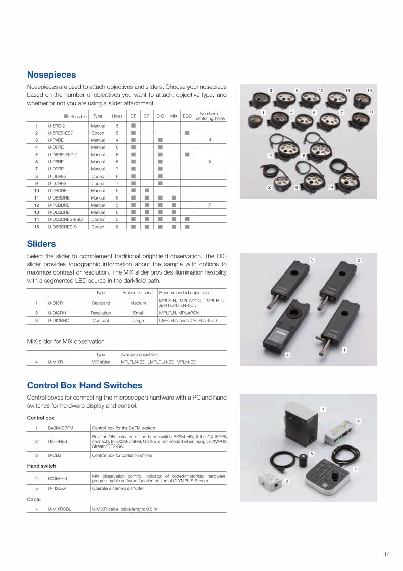
Nosepieces are used to attach objectives and sliders. Choose your nosepiece based on the number of objectives you want to attach, objective type, and whether or not you are using a slider attachment.
Control boxes for connecting the microscope’s hardware with a PC and hand switches for hardware display and control.
Select the slider to complement traditional brightfield observation. The DIC slider provides topographic information about the sample with options to maximize contrast or resolution. The MIX slider provides illumination flexibility with a segmented LED source in the darkfield path.
MIX slider for MIX observation
Type Amount of shear Recommended objectives
1 U-DICR Standard Medium MPLFLN, MPLAPON, LMPLFLN, and LCPLFLN-LCD
2 U-DICRH Resolution Small MPLFLN, MPLAPON
3 U-DICRHC Contrast Large LMPLFLN and LCPLFLN-LCD
Type Available objectives
4 U-MIXR MIX slider MPLFLN-BD, LMPLFLN-BD, MPLN-BD
3 6 12 13 10
2 8 14
9 15
1 4 5 7 11
1
1
3
5
4
2
23
4
: Possible Type Holes BF DF DIC MIX ESD Number of centering holes
1 U-5RE-2 Manual 5
2 U-5RES-ESD Coded 5
3 U-P4RE Manual 4 4
4 U-D6RE Manual 6
5 U-D6RE-ESD-2 Manual 6
6 U-P6RE Manual 6 2
7 U-D7RE Manual 7
8 U-D6RES Coded 6
9 U-D7RES Coded 7
10 U-5BDRE Manual 5
11 U-D5BDRE Manual 5
12 U-P5BDRE Manual 5 2
13 U-D6BDRE Manual 6
14 U-D5BDRES-ESD Coded 5
15 U-D6BDRES-S Coded 6
Control box
1 BX3M-CBFM Control box for the BXFM system
2 GX-IFRESBox for OB indicator of the hand switch BX3M-HS; If the GX-IFRES connects to BX3M-CBFM, U-CBS is not needed when using OLYMPUS Stream/DP2-SAL
3 U-CBS Control box for coded functions
Hand switch
4 BX3M-HS MIX observation control, indicator of coded/motorized hardware, programmable software function button of OLYMPUS Stream
5 U-HSEXP Operate a camera’s shutter
Cable
- U-MIXRCBL U-MIXR cable, cable length: 0.5 m
15
1
2
7
9
5
68
3
4
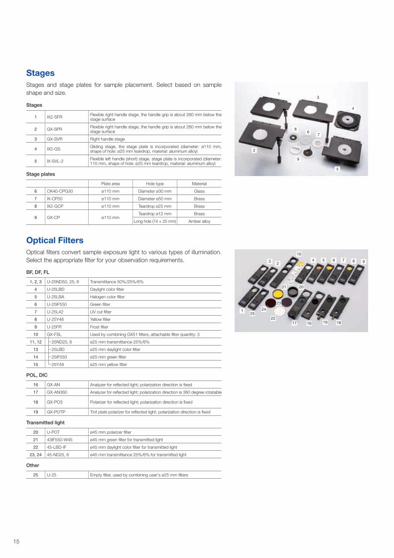
StagesStages and stage plates for sample placement. Select based on sample shape and size.
Stages
1 IX2-SFR Flexible right handle stage, the handle grip is about 260 mm below the stage surface
2 GX-SFR Flexible right handle stage, the handle grip is about 280 mm below the stage surface
3 GX-SVR Right handle stage
4 IX2-GS Gliding stage, the stage plate is incorporated (diameter: ø110 mm, shape of hole: ø25 mm teardrop, material: aluminum alloy)
5 IX-SVL-2 Flexible left handle (short) stage, stage plate is incorporated (diameter: 110 mm, shape of hole: ø25 mm teardrop, material: aluminum alloy)
Stage plates
Plate area Hole type Material
6 CK40-CPG30 ø110 mm Diameter ø30 mm Glass
7 IX-CP50 ø110 mm Diameter ø50 mm Brass
8 IX2-GCP ø110 mm Teardrop ø25 mm Brass
9 GX-CP ø110 mmTeardrop ø12 mm Brass
Long hole (74 × 25 mm) Amber alloy
Optical FiltersOptical filters convert sample exposure light to various types of illumination. Select the appropriate filter for your observation requirements.
1
10
6 8
19 1816
23
17
3 2 9415
13
12
11
14
21
5 7
2225
20
24
BF, DF, FL
1, 2, 3 U-25ND50, 25, 6 Transmittance 50%/25%/6%
4 U-25LBD Daylight color filter
5 U-25LBA Halogen color filter
6 U-25IF550 Green filter
7 U-25L42 UV cut filter
8 U-25Y48 Yellow filter
9 U-25FR Frost filter
10 GX-FSL Used by combining GX51 filters, attachable filter quantity: 3
11, 12 25ND25, 6 ø25 mm transmittance 25%/6%
13 25LBD ø25 mm daylight color filter
14 25IF550 ø25 mm green filter
15 25Y48 ø25 mm yellow filter
POL, DIC
16 GX-AN Analyzer for reflected light; polarization direction is fixed
17 GX-AN360 Analyzer for reflected light; polarization direction is 360 degree rotatable
18 GX-PO3 Polarizer for reflected light; polarization direction is fixed
19 GX-POTP Tint plate polarizer for reflected light; polarization direction is fixed
Transmitted light
20 U-POT ø45 mm polarizer filter
21 43IF550-W45 ø45 mm green filter for transmitted light
22 45-LBD-IF ø45 mm daylight color filter for transmitted light
23, 24 45-ND25, 6 ø45 mm transmittance 25%/6% for transmitted light
Other
25 U-25 Empty filter, used by combining user‘s ø25 mm filters
16
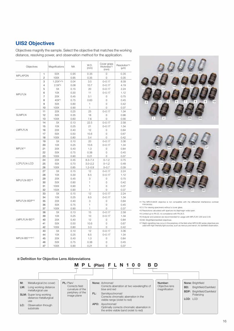
1 The MPLFLN40X objective is not compatible with the differential interference contrast microscopy.
2 0: For viewing specimens without a cover glass.
3 Resolutions calculated with aperture iris diaphragm wide open.
4 Limited up to FN 22, no compliance with FN 26.5.
5 Analyzer and polarizer are recommended for usage with MPLFLN1.25X and 2.5X.
6 BD: Brightfield/darkfield objectives.
7 Slight vignetting may occur in the periphery of the field when MPLN-BD series objectives are used with high-intensity light sources, such as mercury and xenon, for darkfield observation.
UIS2 ObjectivesObjectives magnify the sample. Select the objective that matches the working distance, resolving power, and observation method for the application.
19
11
3
1
43
33
38
27 28 29 30 31 32
39 40 41 42
34 35 36 37
44 45 46 47
2 24 25 26
4 5 6 7 8 9 10
12 13 14 15 16 17 18
20 21 22 23
Objectives Magnifications NA W.D. (mm)
Cover grass thickness*2
(mm)
Resolution*3 (μm)
MPLAPON 1 50X 0.95 0.35 0 0.35
2 100X 0.95 0.35 0 0.35
MPLFLN
3 1.25X*4*5 0.04 3.5 0–0.17 8.394 2.5X*5 0.08 10.7 0–0.17 4.195 5X 0.15 20 0–0.17 2.246 10X 0.30 11 0–0.17 1.127 20X 0.45 3.1 0 0.758 40X*1 0.75 0.63 0 0.459 50X 0.80 1 0 0.42
10 100X 0.90 1 0 0.37
SLMPLN 11 20X 0.25 25 0–0.17 1.3412 50X 0.35 18 0 0.9613 100X 0.60 7.6 0 0.56
LMPLFLN
14 5X 0.13 22.5 0–0.17 2.5815 10X 0.25 21 0–0.17 1.3416 20X 0.40 12 0 0.8417 50X 0.50 10.6 0 0.6718 100X 0.80 3.4 0 0.42
MPLN*4
19 5X 0.10 20 0–0.17 3.3620 10X 0.25 10.6 0–0.17 1.3421 20X 0.40 1.3 0 0.8422 50X 0.75 0.38 0 0.4523 100X 0.90 0.21 0 0.37
LCPLFLN-LCD 24 20X 0.45 8.3–7.4 0–1.2 0.7525 50X 0.70 3.0–2.2 0–1.2 0.4826 100X 0.85 1.2–0.9 0–0.7 0.39
MPLFLN-BD*6
27 5X 0.15 12 0–0.17 2.2428 10X 0.30 6.5 0–0.17 1.1229 20X 0.45 3 0 0.7530 50X 0.80 1 0 0.4231 100X 0.90 1 0 0.3732 150X 0.90 1 0 0.37
MPLFLN-BDP*6
33 5X 0.15 12 0–0.17 2.2434 10X 0.25 6.5 0–0.17 1.3435 20X 0.40 3 0 0.8436 50X 0.75 1 0 0.4537 100X 0.90 1 0 0.37
LMPLFLN-BD*6
38 5X 0.13 15 0–0.17 2.5839 10X 0.25 10 0–0.17 1.3440 20X 0.40 12 0 0.8441 50X 0.50 10.6 0 0.6742 100X 0.80 3.3 0 0.42
MPLN-BD*4*6*7
43 5X 0.10 12 0–0.17 3.3644 10X 0.25 6.5 0–0.17 1.3445 20X 0.40 1.3 0 0.8446 50X 0.75 0.38 0 0.4547 100X 0.90 0.21 0 0.37
M P L (Plan) F L N 1 0 0 B D Definition for Objective Lens Abbreviations
None: Brightfield
BD: Brightfield/Darkfield
BDP: Brightfield/Darkfield/ Polarizing
LCD: LCD
Number: Objective lens magnification
M: Metallurgical (no cover)
LM: Long working distance metallurgical use
SLM: Super long working distance metallurgical use
LC: Observation through substrate
None: Achromat/ Corrects aberration at two wavelengths of blue and red
FL: SemiApochromat/ Corrects chromatic aberration in the visible range (violet to red)
APO: Apochromat/ Optimally corrects chromatic aberration in the entire visible band (violet to red)
PL: Plan/ Corrects field curvature of the periphery of the image plane
17
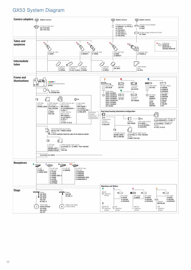
GX53 System Diagram
C-mount video portGX-TV0.5XCGX-TV0.7XC
Camera adapters
Tubes and eyepieces
Intermediate tubes
Frame and illuminations
Nosepieces
Digital camera
EyepiecesWHN10XWHN10X-HCROSS WHN10X
Binocular tubeU-BI90
Binocular tubeU-BI90U-BI90CT
For BFU-5RE-2U-5RES-ESD
Stage
Digital camera Digital camera
×2GX53 microscope standGX53F
For BF with slider slotU-P4REU-D6REU-D6RE-ESD-2U-P6REU-D7REU-D6RESU-D7RES
For BF/DFU-5BDRE
For BF/DF with slider slotU-D5BDREU-P5BDREU-D6BDREU-D5BDRES-ESDU-D6BDRES-S
EyepointadjusterU-EPA2
EyepointadjusterU-EPA2
EyepointadjusterU-EPA2
Magni�cationchangerU-CA, U-ECA
Binocular tubeU-BI90CT
Binocular tubeU-TBI90
Dual portGX-SPU
Trinocular tubeU-TR30H-2
Intermediate tubeIX-ATU
Camera mount adapterU-CMAD3 + U-TV1X-2U-TV1XCU-TV0.63XCU-TV0.5XC-3U-TV0.35XC-2U-TV0.25XC
Camera mount adapterU-FMTU-CMT
Primary image camera port tubeIX-TVAD
Dual lamp housing attachment con�guration
Double lamp housing attachmentU-DULHA
AdapterMX-HGAD
LED light sourceBX3M-LEDR +MX-LLHECBL
100W halogen light sourceU-LH100L-3 +TH4-100/200Option:U-RMT/TH4-HS
Light guide sourceU-LLGAD + U-LLG150/300 + U-HGLGPS
100W mercury apo light sourceU-LH100HGAPO + U-RFL-T100W mercury light sourceU-LH100HG + U-RFL-TOption:U-CST, U-CLA
Stage mirrorCK40M-MS
100W mercury apo light sourceMX-HGAD + U-LH100HGAPO + U-RFL-T100W mercury light sourceMX-HGAD + U-LH100HG + U-RFL-TOption:U-CST, U-CLA
Transmitted light illuminationIX2-ILL100 + PMG3-LWCDOption:U-POT/43IF550-W45/45-LBD-IF/45-ND6/45-ND25
100W halogen light sourceU-LH100L-3 +TH4-100/200Option:U-RMT/TH4-HS
LED light sourceBX3M-LEDR
Light guide source MX-HGAD +U-LLGAD + U-LLG150/300 + U-HGLGPS
Controller for GX53
100W halogen light sourceU-LH100L-3 + U-RMT+ TH4-100/200Option:TH4-HS
LED light sourceBX3M-LEDT + BX3M-PSLED
StageGX-SFRIX2-SFRGX-SVRIX2-GSIX-SVL-2
Insert plateCK40-CPG30IX-CP50IX2-GCPGX-CP
StageIX2-GSIX-SVL-2
Stage insert plate (incorporated)
Polarizer GX-PO
Tint plate polarizerGX-POTP
Filter sliderGX-FSL
ND �lter slidersU-25ND6U-25ND25U-25ND50Filter slidersU-25LBDU-25IF550U-25Y48U-25L42U-25FRU-25LBAU-25
AnalyzerGX-AN
Rotatable analyzer GX-AN360
ND �lters25ND625ND25Filters25FR25LBD25IF550
Scale sliderGX-SLM
Scale �ltersGX51-SLMG5GX51-SLMG10GX51-SLMG20GX51-SLMG50GX51-SLMG100GX51-SLMGSGX51-SLMGHGX-SLMG
Dual lamp housing attachment con�guration
Objectives and Sliders
BFobjective lenses
BF/DFobjective lenses
BFobjective lenses
DIC sliderU-DICRU-DICRHU-DICRHC
BF/DF objective lenses
DIC sliderU-DICRU-DICRHU-DICRHC
MIX sliderU-MIXR
BFobjective lenses
DIC sliderU-DICRU-DICRHU-DICRHCAdapter
BD-M-AD
18
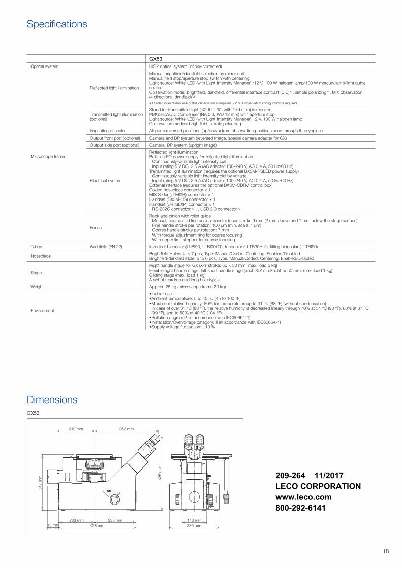
Specifications
GX53
Dimensions
213 mm
203 mm
317
mm
363 mm
425
mm
235 mm438 mm61 mm
140 mm280 mm
GX53Optical system UIS2 optical system (infinity-corrected)
Microscope frame
Reflected light illumination
Manual brightfield/darkfield selection by mirror unitManual field stop/aperture stop switch with centeringLight source: White LED (with Light Intensity Manager) /12 V, 100 W halogen lamp/100 W mercury lamp/light guide source Observation mode: brightfield, darkfield, differential interface contrast (DIC)*1, simple polarizing*1, MIX observation (4 directional darkfield)*2
1 Slider for exclusive use of this observation is required. 2 MIX observation configuration is required.
Transmitted light illumination (optional)
Stand for transmitted light (IX2-ILL100: with field stop) is requiredPMG3-LWCD: Condenser (NA 0.6, WD 12 mm) with aperture stopLight source: White LED (with Light Intensity Manager) 12 V, 100 W halogen lampObservation modes: brightfield, simple polarizing
Imprinting of scale All ports reversed positions (up/down) from observation positions seen through the eyepiece
Output front port (optional) Camera and DP system (reversed image, special camera adapter for GX)
Output side port (optional) Camera, DP system (upright image)
Electrical system
Reflected light illuminationBuilt-in LED power supply for reflected light illumination
Continuously-variable light intensity dialInput rating 5 V DC, 2.5 A (AC adapter 100–240 V, AC 0.4 A, 50 Hz/60 Hz)
Transmitted light illumination (requires the optional BX3M-PSLED power supply)Continuously-variable light intensity dial by voltageInput rating 5 V DC, 2.5 A (AC adapter 100–240 V, AC 0.4 A, 50 Hz/60 Hz)
External interface (requires the optional BX3M-CBFM control box)Coded nosepiece connector × 1MIX Slider (U-MIXR) connector × 1Handset (BX3M-HS) connector × 1Handset (U-HSEXP) connector × 1
RS-232C connector × 1, USB 2.0 connector × 1
Focus
Rack and pinion with roller guideManual, coarse and fine coaxial handle; focus stroke 9 mm (2 mm above and 7 mm below the stage surface)Fine handle stroke per rotation: 100 μm (min. scale: 1 μm)Coarse handle stroke per rotation: 7 mmWith torque adjustment ring for coarse focusingWith upper limit stopper for coarse focusing
Tubes Widefield (FN 22) Inverted: binocular (U-BI90, U-BI90CT), trinocular (U-TR30H-2), tilting binocular (U-TBI90)
Nosepiece Brightfield Holes: 4 to 7 pcs, Type: Manual/Coded, Centering: Enabled/Disabled Brighfield/darkfield Hole: 5 to 6 pcs, Type: Manual/Coded, Centering: Enabled/Disabled
Stage
Right handle stage for GX (X/Y stroke: 50 × 50 mm, max. load 5 kg)Flexible right handle stage, left short handle stage (each X/Y stroke: 50 × 50 mm, max. load 1 kg)Gliding stage (max. load 1 kg)A set of teardrop and long hole types
Weight Approx. 25 kg (microscope frame 20 kg)
Environment
•Indoor use•Ambient temperature: 5 to 40 °C (45 to 100 °F)• Maximum relative humidity: 80% for temperatures up to 31 °C (88 °F) (without condensation) In case of over 31 °C (88 °F), the relative humidity is decreased linearly through 70% at 34 °C (93 °F), 60% at 37 °C (99 °F), and to 50% at 40 °C (104 °F).
•Pollution degree: 2 (in accordance with IEC60664-1)•Installation/Overvoltage category: II (in accordance with IEC60664-1)•Supply voltage fluctuation: ±10 %
209-264 11/2017LECO CORPORATIONwww.leco.com800-292-6141