Embed Size (px)
Citation preview

Aalborg Universitet
Optimization of Front Axle Suspension System of Articulated Dump Truck
Langer, Thomas Heegaard; Christensen, Brian B.; Mouritsen, Ole Østergaard; Hansen,Michael RygaardPublished in:Proceedings of the First Joint International Conference on Multibody System Dynamics: CD-ROM
Publication date:2010
Document VersionAccepted author manuscript, peer reviewed version
Link to publication from Aalborg University
Citation for published version (APA):Langer, T. H., Christensen, B. B., Mouritsen, O. Ø., & Hansen, M. R. (2010). Optimization of Front AxleSuspension System of Articulated Dump Truck. In Proceedings of the First Joint International Conference onMultibody System Dynamics: CD-ROM
General rightsCopyright and moral rights for the publications made accessible in the public portal are retained by the authors and/or other copyright ownersand it is a condition of accessing publications that users recognise and abide by the legal requirements associated with these rights.
? Users may download and print one copy of any publication from the public portal for the purpose of private study or research. ? You may not further distribute the material or use it for any profit-making activity or commercial gain ? You may freely distribute the URL identifying the publication in the public portal ?
Take down policyIf you believe that this document breaches copyright please contact us at [email protected] providing details, and we will remove access tothe work immediately and investigate your claim.
Downloaded from vbn.aau.dk on: juni 12, 2018

The 1st Joint International Conference on Multibody System DynamicsMay 25–27, 2010, Lappeenranta, Finland
Optimization of Front Axle Suspension System of Articulated Dump Truck
Thomas H. Langer∗, Brian B. Christensen∗, Ole Ø. Mouritsen#, Michael R. Hansen†
∗ Research & Development DepartmentA/S Hydrema Produktion
Gl. Kirkevej 16, 9530 Støvring, Denmarke-mail: [email protected], [email protected]
# Depart. of Mechanical and Manufacturing EngineeringAalborg University
Pontoppidanstræde 101, 9220 Aalborg Ø, Denmarke-mail: [email protected]
† Department of EngineeringUniversity of Agder
Serviceboks 509, 4898 Grimstad, Norwaye-mail: [email protected]
ABSTRACT
Manufacturers of construction machinery are challenged toaccommodate legal requirements on the vibra-tion exposure associated with their products. For such machines a crucial performance parameter is thewhole body vibration level that the operator is subjected to.
This paper presents results from ongoing research collaboration between Hydrema Produktion A/S, AalborgUniversity and the University of Agder on comfort improvement. The main goal of the research project isto improve ride comfort of articulated construction machinery by use of multibody simulation models.
In this paper the application that has been subjected to comfort improvement is a two axle articulated dumptruck. The comfort has been in terms of whole body vibration exposure and the overall improvement hasbeen made possible by adding front axle suspension. However, a hydraulic stabilizing system between thetractor and trailer of the machine and the varying load distribution when turning the steering wheel hasrevealed a non-trivial task of sizing the new suspension system in an optimal way.
Hydraulic accumulators and valves are used as suspension elements. The topology of the suspension frameis given together with a work cycle used to evaluate the wholebody vibrations.
By use of a multibody simulation model of the dump truck the whole body vibration exposure has beencomputed using the predefined work cycle as model input. The design parameters comprise the compo-nents of the hydraulic subsystem of the suspension, i.e., the size of the hydraulic accumulators and theinitial gas pressure as well as the size of the damping orifices. The design criteria has been the comfort asevaluated from the typical work cycle with a number of side constraints such as availability of components,available space, collision avoidance and design rules given by the supplier of accumulators.
A non-gradient optimization routine has been applied to determine the optimal design, i.e., the design withthe best possible ride comfort in terms of whole body vibrations that does not violate any of the constraints.Some variables have been treated as discrete such as the accumulator volume. In general, the results havebeen encouraging and may be used directly as guidelines in both current and future design.
Keywords: ride comfort, suspension, construction machinery, optimization, discrete design variables.

1 INTRODUCTION
Ride comfort has become an important competitive parameteramong manufacturers of mobile machines,including construction machinery such as earth moving equipment. The reason for this is mainly legal re-quirements. The European directive 2002/44/EC defines somelimits for the daily exposure to vibrationsexperienced by human operators [21]. For whole body vibration these directives pose a non-trivial chal-lenge to accommodate with the equipment available on the market today.
The manufacturers are required to declare the vibration exposure associated with the use of the machinery.This prompts two challenges.
The first is getting information on realistic and representative duty cycles, as there is no standardized dutycycles from which the whole body vibration level should be declared. The first and only attempt to defineduty cycles for construction equipment is the technical specification ISO 25398 which were approved bythe European Committee for Standardization on April 18 2008[4]. It defines for example that an articulatedframe dumper undergoes 1) A loading process 2) travel with load 3) unloading and 4) travel without load.Though no information is given on travel speed, duration of the different operations or condition of thesoil on which the dumper is travelling. The technical specification lists some equivalent vibration valuesfor different kinds of construction machinery. Experiments emphasize that variation of travel speed runningover obstacles is pivotal to the vibration exposure on the operator [8] [16]. Also there is big difference in thedynamic response of a small dump with a 10 tons capacity and a big dump truck used in the mining industry.
The other challenge is to evaluate and improve the ride comfort of the machinery. Improvement of ridecomfort requires proper choices of the components for suspension systems. Often the design will be re-stricted by commercially available components. Evaluation and improvement of ride comfort is carried outmost cost efficiently by model based prototyping [3] [10]. In a computer model it is possible to changeparameters and evaluate the performance in a cost efficient way compared to changing and testing a fullscale prototype. But the model has to be able to evaluate the ride comfort in terms of whole body vibration.The calculation scheme for this is specified in ISO 2631 [1]. Doing the evaluation by simulation modelsrequires a three dimensional multibody simulation model with the ability to handle off-road soil conditions.
Figure 1. Hydrema 912DS Articulated Dump Truck.
In this paper a hydraulic suspension design for a 10 tonnes articulated dump truck, Figure1, is presentedand possible design variables are identified. Some design rules are introduced that effectively limits thefeasible design space improving the chances of finding a proper design. Multibody dynamics simulationis applied together with a non-gradient optimization routine to find the best combination of componentswithout violating the side constraints.
2 MODELLING
Hydrema Produktion A/S has in collaboration with Aalborg University and University of Agder developedan in-house three dimensional multibody code in Fortran 90.The program is able to simulate some of theHydrema vehicles. The program is build up in modules and the model can easily be parameterized. For thisresearch the multibody simulation code has been used to simulate the Hydrema 912DS Dumper, Figure2.

t
-
1
2
3
4
5
6
7
8
9
1011
12
XY
Z
Figure 2. Hydrema 912DS Articulated Dump Truck consisting of 12 bodies.
The governing equations for the mechanical system consist of a set of second order differential equationsand a set of algebraic equations. The entire set of equationsis listed in Equation1:
[
M −ΦTq
Φq 0
] [
h
λ
]
=
[
gext − b
γ
]
(1)
The governing equations for the hydraulic stabilizing system consist of a set of first order differential equa-tions given by:
p = C · h + π (2)
In Equation1 g ext is a vector containing the generalized external forces acting on each body. Gravity, hy-draulic cylinder forces, springs and dampers, propel torque and the tire-ground interactions all contribute tocomponents ofg ext. The stiffness and damping characteristics of rubber bushing and springs and dampersare described by linear and second order formulations. The wheels are modeled as individual bodies. Theexternal force components acting on the wheels are the reaction forces between the terrain and wheels. Theforce contributions from the hydraulic cylinders are calculated from the pressure states in the hydrauliccircuits such as stabilizing system, steering system and suspension system. The pressure gradients,p , arecomputed from Equation2 that is based on mass conservation and assumed Newtonian fluids yielding a setof decoupled equations.
For the numerical time integration of the initial value problem a fixed step integrator is applied. The dynam-ics of the hydraulic system is considerably stiffer than thedynamics of the mechanics. Therefore a smallertime step is applied for integration of the hydraulic statesof Equation2. By interpolation of the states ofthe mechanics it is possible to integrate the hydraulic gradients by smaller steps, see also [12].
In order to be able to evaluate realistic ride comfort on off-road conditions the tire response is crucial. Inthe multibody simulation code a tire model developed for off-road vehicles with big tires is applied. Themodel needs only few modeling parameters and is able to handle short wave terrain with obstacles, see also[19].
To control the dumper in the simulation model two inputs are used. The first one is the forward/backwardspeed. A reference speed is given and a PI Controller adjuststhe torque on the drive shaft and an opposite

torque where the engine is mounted. The other input is a path that the dumper should follow. The steering isdone by opening and closing valves connected to the two steering cylinders between the articulated frames.A controller is applied to convert the offset between the dumper and the path to a valve opening signal. Thecontroller is described in more detail in [24].
0 2 4 6-10
-5
0
5
10
15Cabin Acceleration
0 2 4 6-15
-10
-5
0
5
10
15Seat Acceleration
Acc
eler
atio
n[m
/s2
]
Cabin Seat
Time [s]Time [s]
Figure 3. Comparison of vertical accelerations from the simulation (green) of thecabin and seat withthe dynamic response of full scale measurement (black).
In order to evaluate the whole body vibration level in accordance with the ISO 2631 [1] digital filters arebuild into the model to handle the frequency weightings of the acceleration response. The digital filtersare implemented as described in [23] and facilitate the calculation of the vibration exposure for each of thethree directions as the RMS value of the weighted acceleration:
aw(direc) =
[
1
T
∫ T
0
a2w(direc)(t)dt
]12
(3)
Now the whole body vibration level is defined as the largest ofthe three vibration values with a scalarweighting on the x and y direction:
aw,max = max {1.4aw,x; 1.4aw,y; aw,z} (4)
The simulation code is explained in more detail in [18]. Before any design changes was made the dynamicresponse of the exiting dumper has been compared to measurement, Figure3, for a specific test track. Thesimulated response of the cabin and seat is in reasonable accordance with the reality. The vertical frequencyweighted root-mean-square accelerationawz for the simulation model is0.86. The measuredawz is 1.11.By experience the measured value will always be higher than the simulated because of the contribution ofvibration from engine, gearbox, etc. Though there is a difference between simulation and measurements itis concluded that the model is well suited for evaluating theperformance since the frequency response fitsquite well which is considered crucial when evaluating whole body vibrations.
3 CONSIDERED SYSTEM
As the Hydrema 912DS has stiff axles the topology shown in Figure4 has been chosen as front axle sus-pension. The front axle is mounted at the tractor behind the axle in a spherical joint. The sideway forces areprimarily transmitted through a Panhard tension/compression bar. The vertical forces are transmitted viathe two suspension cylinders as seen in Figure4.

Accumulator
CylinderA-frame
Spherical Joint
Panhard Bar
Stiff Wheel Axle
Roll Stabilizer
Figure 4. Front axle suspension design.
On Figure5 a simplified diagram is shown of one hydraulic suspension circuit. The ring side of the cylinderis connected to tank pressure with a thick hose and big fittings to minimize flow induced pressure losses.The bottom side of the cylinder contains the oil pressure which carries the load from the dumper. Thischamber is connected to a hydraulic accumulator through a direction valve parallel with an orifice.
Work of principal is that when the front wheel of the dumper hits an obstacle the oil from the bottom cham-ber should easily be displaced to the accumulator. The accumulator will afterwoods try to displace the oilback in the cylinder chamber when the pressure in the cylinder decreases again. On its way back is has topass through the orifice.
Hereby the accumulator represents a hydro-pneumatic spring of a suspension system and the orifice repre-sents damping. These represent the main components in the suspension circuit. Besides a very slow leveladjustment system is connected to the suspension circuit. It can supply or displace oil from the system.Because the supply system is throttled down it has no influence of the dynamics and is not modeled. Thesupply pressure is kept constant at 125 bar.
dc
d0pt
psupp
V0
p0
Figure 5. Characteristics of direction valve and orifice.
The direction valve is modeled as fully open/fully closed depending on the pressure difference between oilin the cylinder and the oil in the accumulator. The orifice is described by the orifice equation assumingturbulent flow. The accumulator is described by [22]:

constant = p · V n (5)
p is the pressure,V is the volume of the gas andn is the polytrophic exponent which can vary from 1 to1.67 [11].
To find the operational contraction valueCd of the orifice the pressure difference between cylinder andaccumulator has been plotted as a function of the cylinder speed. Aware that the oil is compressible it stillgives a reasonable indication of the response as seen in Figure6. The blue dots are measurements. A model
Pre
ssur
eD
iffer
enceb
ar
Cylinder Speedm/sFigure 6. Characteristics of direction valve and orifice.
of the direction valve and the orifice was made in MATLAB with the cylinder travel as input. The contrac-tion valueCd is adjusted to an operational value of1 which gives the characteristics shown by the red curvein Figure6. The plot on Figure6 also indicates that the direction valve and the orifice can bemodeled asturbulent flow.
The space on the considered machine is very limited. Therefore the topology design changes are very lim-ited. The stroke of the cylinders is given by the design engineer to80mm. Because of the limitation on thespace, there are the following design variables left: Volume of the accumulatorV0, initial pressure of theaccumulatorp0, the diameter of the cylinderdc, the diameter of the return orificedo and the stiffness of theroll stabilizer rubber block calledk and some clearancecr before the roll stabilizer acts.
Observing the 6 design variables reveals that they may be divided into two categories:
1. Discrete:yd = {dc V0}
2. Continuous:yc = {p0 d0 k cr}
Hydraulic cylinders are produced by Hydrema in standard dimensions. Some possible cylinders are listedin Table3 in Appendix I. From the supplier a number of nitrogen accumulators are extracted in a range offeasible sizes, Table4 in Appendix I. Each accumulator are subjected to some properties in terms of thepermitted operating pressurepper it can stand and a permitted pressure ratioPPR which is the maximumbetween the duty pressure and the initial pressure of the accumulatorp0.

4 IMPROVEMENT OF DESIGN
An optimization problem is in general formulated as the minimization of an objective functionO subjectedto n inequality constraints andm equality constraints:
min O(y) (6)
gi(y) < 0.0 i = 1...n (7)
hi(y) = 0.0 i = 1...m (8)
where,y =
[
y(d)
y(c)
]
, is the vector of design variables. The objective function and the inequality constraints
may be combined to form an augmented penalty functionΘ that can be subjected to minimization:
minΘ(y) = O(y) +
n∑
i=1
Gi(y) (9)
Gi(y) =
{
0g2
i (y)gi(y) ≥ 0gi(y) < 0
(10)
In this case the objective function is the ride comfort in terms of whole-body vibration exposure fromEquation4. As mentioned an articulated dump truck operates accordingto ISO 25398 within four modes:Loading process, travel with load, unloading, travel without load [4]. Experiences shows that the criticaloperation mode for a dump truck regarding ride comfort is travel [5] [8] [20].For agricultural tractors a standardized test track, ISO 5008, is used to evaluate the ride comfort [2]. Toevaluate the ride comfort of the Hydrema dump truck the100m smooth track specified in ISO 5008 is ap-plied, Figure7(a). ISO 5008 prescribes three different speeds. Here the14km/h speed is applied for anempty dump truck and10km/h for a fully loaded dump truck.
(a) ISO 5008 smooth track. (b) Load distribution at the front wheels whenfully steered out.
Figure 7.
An articulated vehicle is to a high degree characterized by the displacement of the center of gravity whenthe vehicle is steered out. This results in an unsymmetricalload distribution on the wheels, Figure7(b),and some stability issues often have to be considered [9] [17]. Applying front axle suspension to an articu-lated machine will cause the tractor to body roll because of the asymmetric load distribution. The hydraulicstabilizing system between the tractor and trailer counteract for some of the body roll movement. It isexperienced that body roll movement of the tractor is discomfortable when the suspension cylinder strokedifference (SCSD) is over30mm when fully steered out, which require a side constraint to the optimizationof the suspension. This is evaluated by a short simulation with and without load making a fully right turn.
Hereby 4 simulations are used to evaluate the quality of a configured suspension:
1. Fully right turn without load.
2. Fully right turn with load.
3. Travel without load at the ISO 5008 smooth track at14km/h.
4. Travel with load at the ISO 5008 smooth track10km/h.
Besides the side constraint of the SCSD, there are 7 other side constraints for the suspension system givenby the chosen design and the supplier of the accumulators:
1. Maximum peak pressure should not exceedp0 · PPR [15].
2. Maximum peak pressure should not exceedpper [15].
3. p0 should be higher than 90 percent of the minimum duty pressure[15].
4. The gas volume should not exceedV0 · 0.9 or be less than zero (2 constraints) [15].
5. The suspension cylinders should not reach the end stops (2constraints).
The objective function as well as the contributions from theside constraint violations to the augmentedobjective functions are all normalized. The value of the augmented objective function appears by addingthe whole-body vibration exposure with the square of all side constraint violations.[13] and [14] suggest that the discrete design variables are handled as continuous and then, in order to obtainan optimal design that is actually useful to apply on real world applications, an integer evaluation numberGu is added to the augmented objective function:
Gu =2
∑
j=1
(
ui − i
ǫ
)2
(11)
wherei is the rounded integer value ofu andǫ is a parameter that is gradually reduced. In practice this isdone by listing the discrete design variables in tables likeTable3 and Table4 considering the index numberat the left as the design variables and then interpolating between the rows when doing the evaluation.
To minimizeΘ(y) the complex method first presented by [7] is applied. It is a non-gradient based mappingmethod that uses a population of design called a complex. Thecomplex containsq design. Each configu-ration is evaluated with respect to Equation9. Then the design with the highest objective value is changed.This is done by mirroring it in the center of the remaining design by:
ynew
= κ · (yc− y
worst) + y
c, y
c=
∑q
i6=worst yi
q − 1(12)
κ is called the reflection constant which is set to1.3 as originally suggested by [7]. If the newly mirroreddesign continues to evaluate as the worst design it is moved toward the currently best design. The algorithmfor this depends on the number of successive mirror operations that has returned the particular design as theworst design,k:
ynew
=1
2·(
yworst
+ ǫ · yc+ (1 − ǫ) · y
best
)
+ σ (13)
ybest
is the currently best design andǫ is:
ǫ =
(
nr
nr + k − 1
)(nr+k−1
nr)
(14)
In Equation14 nr is a tuning parameter set to 4 andσ in Equation13 is an extra term suggested by [6]that takes into account a situation where the centroidy
ccoincides with a local minimum of the objective
function:σ = (y
c− y
best)(1 − ǫ)(2 · R − 1) (15)
R is a random number between 0 and 1.[7] suggests a population size that is twice the number of design variables and that is adopted here.

5 RESULTS
In figure8 the development in the augmented objective function for thefittest member of the population isshown. The criteria of converge is that the difference between the best and worst configuration should beless than0.01. Whenǫ is reduced, an increasement of the fittest member is observed, and then the solutionconverge again but to a higher value than before.
0 20 40 60 80 100 1200.7
0.8
0.9
1
1.1
1.2
1.3
1.4
1.5
150 200 250 3000.72
0.725
0.73
0.735
0.74
0.745
0.75
0.755
Number of iterationsNumber of iterations
ΘΘ
ǫ = 2.00
ǫ = 0.20
ǫ = 0.02
Figure 8. Development of augmented objective function value of fittest member.
In figure9 the development of the cylinder diameter and the accumulator size are shown by table indices.The values moves toward integer values as wanted.
0 50 100 150 200 250 300 3500
1
2
3
4
5
6
7
8
9
Number of iterations
Tabl
ein
dex
V0
dc
Figure 9. Development of the two discrete design variables.
In table1 the optimized design of the suspension system is shown.
The final design is about twice as good as the best member of thestart population.As no side constraints are violated in the final design the augmented object function value express thewhole-body vibration exposure. Compared to the Hydrema dump truck without front axle suspension the

dc V0 p0 d0 k cr
85mm 1l 23.4bar 3.23mm 1.94 · 106 Nm
1.77mm
Table 1. Final optimized design.
whole-body vibration exposure on this specific track is decreased from1.54m · s−2 to 0.73m · s−2, whichis a significant improvement.
Since the polytrophic exponentn can vary in a quite wide range [11] the whole-vibration exposure isevaluated for the final design propose with different sizes of the polytrophic exponent. From table2 anegliable difference in the vibration level is observed as function of the polytrophic exponent size.
Polytrophic exponentn 1.0 1.2 1.4 1.67WBV level 0.729 0.728 0.730 0.731
Table 2. Vibration level with different operational sizes of the polytrophic exponent.
In Appendix II a shorter simulation right front wheel hitting an30mm obstacle is used to optimize theconfiguration of the suspension system in the same way as on the test track. It seems there is no significantdifference in the final configuration for the100m long test track and the single obstacle. The discrete designvariables becomes the same as there is small deviation in thecontinuous variables. This indicates that thecomfort number is independent of track length and much more dependant of the system eigenfrequency andavoiding end-stops of the suspension system, which is supported by [25].
6 CONCLUSIONS
By a non-gradient optimization method the optimum configuration of six design variables are fund for ahydro-pneumatic suspension system for an articulated dumptruck. The evaluation criterion is a minimumlevel of whole-body exposure with a number of side constraints. Among these is the tolerable body rollwhen turning.
Two discrete design variables are handled as continuously and then an augmented objective restrict the de-sign variables to become exact components in a library. Hereby it is demonstrate that discrete variables indesign optimization of real world application can be done effectively.
Experimental work has been done to find operational values ofthe orifice equation and to ensure that theflow acts turbulent in order to have the right equation for thephysical phenomena. The operational poly-trophic exponent though is difficult to determine. A sensitivity study has shown that the vibration value isvery little dependent of the size of the polytrophic exponent.
Optimization has been carried through with a100m long standardized test track and a single small obstacle.The optimum design configuration becomes very similar. Thisresult encourages using short simulationsonly in future work. This will decrease evaluation time for adesign and though the overall developmenttime.
For the specific problem the optimization routine has found that the accumulator with the highest volumegives the lowest whole-body vibration. This result call foran evaluation with accumulators with highervolume and then the design engineer must check out, if is possible to implement such a high volume accu-mulator.

ACKNOWLEDGEMENT
The authors would like to thank R&D Manager T. K. Iversen, A/SHydrema Produktion for help, adviceand cooperation on this work.
The research work is funded by an Industrial PhD-grant from the Danish Agency for Science, Technologyand Innovation under the Danish Ministry of Science, Technology and Innovation.
REFERENCES
[1] ISO 2631-1 Mechanical vibration and shock Evaluation of human exposure to whole-body vibrationPart 1: General requirements. International Organization for Standardization, 1997.
[2] ISO 5008 Agricultural wheeled tractors and field machinery -Measurement of whole-body vibrationof the operator. International Organization for Standardization, 2002.
[3] Aktiv vibrationsdæmpning.Panorama(2007), 14–15.
[4] ISO 25398 Earth-moving machinery - Guidelines for assessment of exposure to whole-body vibrationof ride-on machines - Use harmonized data measured by international institutes, organizations andmanufacturers. International Organization for Standardization, 2008.
[5] HSE information sheet: Whole-body vibration in quarries.http://www.hse.gov.uk/vibration/wbv/quarries.pdf, 2010.
[6] A NDERSSON, J. A survey of multiobjective optimization in engineeringdesign. Technical LiTH-IKP-R-1097, Department of Mechanical Engineering, Linköping Unversity, Linköping, Sweden.
[7] BOX, M. J. A new method of constraint optimization and a comparison with other methods.ComputerJournal 8(1965), 42–52.
[8] CHRISTENSEN, B. B., AND LANGER, T. H. Experimental evaluation of whole body vibration on ahydrema 912DS dumper. Test report, A/S Hydrema Produktion,Støvring, 2009.
[9] DUDZINSKI , P. Projektierung mobiler arbeitsmaschinen mit virtuellen und experimentellen metho-den. Tech. rep., Technische Universität Wroclaw (Breslau).
[10] FILLA , R., AND PALMBERG, J. O. Using dynamic simulation in the development of constructionmachinery. InProceedings of the Eight Scandinavian International Conference on Fluid Power(Tam-pere, Finland, 2003).
[11] GILIOMEE , C. L. Mathematical modelling of hydraulic accumulators. University of Pretoria etd,2005.
[12] GONZALEZ, F., GONZALEZ, M., AND CUADRADO, J. Weak coupling of multibody dynamics andblock diagram simulation tools. InProceedings of the ASME 2009 International Design EngineeringTechnical Conference and Computers and Information in Engineering Conference(San Diego (CA),USA, Sept. 2009), ASME.
[13] HANSEN, M. R., AND ANDERSEN, T. O. Design optimization of hydralically actuated lifting tableusing mapping techniques. InProceedings of the Ninth Scandinavian International Conference onFluid Power SICFP(Linköping, Sweden, June 2005).
[14] HANSEN, M. R., AND ANDERSEN, T. O. A method for linked discrete design variables appliedtolifting tables. InProceedings of the 12th AIAA/ISSMO Multidisciplinary Analysis and OptimizationConference(Victoria, British Columbia Canada, Sept. 2008), AmericanInstitute of Aeronautics andAstronautics.
[15] HYDAC. Diaphragm accumulators welded types. http://www.hydac.com/de-en/products/hydraulic-accumulators/diaphragm-accumulators/diaphragm-accumulators-welded-types.html.
[16] JÖNSSON, P., AND LÖFROTH, C. RESULT: mobil provbana för standardiserad vibrationsmætning.Tech. Rep. 2, Skogforsk, Uppsala, Sweden, 2007.
[17] LANGER, T. H. Analysis of the 912 pendulum bar length influence on load distribution. Calculationand analysis, A/S Hydrema Produktion, Støvring, Feb. 2010.
[18] LANGER, T. H., AND BAK , M. K. Dynamic simulation for evaluation and improvement ofridecomfort in a hydrema ADT, 2008.
[19] LANGER, T. H., MOURITSEN, O. Ø., EBBESEN, M. K., AND HANSEN, M. R. A tire model for Off-Highway simulation and comfort evaluation. InProceedings of the ASME 2009 International DesignEngineering Technical Conference and Computers and Information in Engineering Conference(SanDiego (CA), USA, Sept. 2009).
[20] MAYTON , A. G. Evaluation of whole-body vibration exposures for haulage truck and loader operatorsin quarry operations. InProceedings of the ASME 2009 International Design Engineering TechnicalConference and Computers and Information in Engineering Conference(San Diego (CA), USA, Sept.2009).
[21] PARLIAMENT , E., AND OF THE EUROPEAN UNION, C. Directive 2002/44/EC of the european par-liament and of the council of 25 june 2002 on the minimum health and safety requirements regardingexposure of workers to the risks arising from the physical agents (vibration).
[22] RASMUSSEN, P. W., IVERSEN, F., HALLING , B., HOUNSGAARD, G., MØLBAK , H. G., KRIS-TENSEN, F. D., LYNGBÆK, E., RASMUSSEN, N. B., JESSEN, B. B., AND JANNERUP, O. HydraulikStåbi. Teknisk Forlag A/S, 1996.
[23] RIMELL , A. N., AND MANSFIELD, N. J. Design of digital filters for frequency weightings requiredfor risk assessments of workers exposed to vibration.Industrial Health 45(2007), 512–519.
[24] SAEKI , M. Path following control of articulated vehicle by backward driving. InProceedings of the2002 IEEE International Conference on Control Applications (Sept. 2002).
[25] TOSCANO, J. Improving operator comfort. http://www.sae.org/mags/sohe/6727, Aug. 2009.

APPENDIX I
COMPONENT LIBRARY
This appendix contains tabel for standard sizes of hydraulic cylinders and hydraulic accumulators.
dc Piston Diameter [mm]1 632 803 854 905 120
Table 3. Standard piston sizes.
V0 VolumeV0 [L] Permitted Operating Pressurepper [Bar] Permitted Pressure RatioPPR1 0.075 250 82 0.16 300 83 0.32 300 84 0.50 210 85 0.60 330 86 0.75 330 87 1.00 200 88 1.00 330 4
Table 4. Available accumulators sizes [15].
APPENDIX II
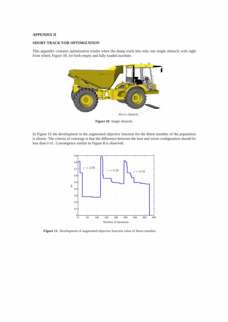
SHORT TRACK FOR OPTIMIZATION
This appendix contains optimization results when the dump truck hits only one single obstacle with rightfront wheel, Figure10, for both empty and fully loaded machine.
30mm obstacle.
Figure 10. Single obstacle.
In Figure11 the development in the augmented objective function for thefittest member of the populationis shown. The criteria of converge is that the difference between the best and worst configuration should beless than0.01. Convergence similar to Figure8 is observed.
0 50 100 150 200 250 300 350 4000
0.1
0.2
0.3
0.4
0.5
0.6
0.7
0.8
0.9
Number of iterations
Θ
ǫ = 2.00ǫ = 0.20 ǫ = 0.02
Figure 11. Development of augmented objective function value of fittest member.

In table5 the optimized design of the suspension system is shown.
dc V0 p0 d0 k cr
85mm 1l 26.6bar 3.32mm 1.89 · 106 Nm
1.28mm
Table 5. Final optimized design.
In figure12 the development of the cylinder diameter and the accumulator size are shown by table indices.The values moves toward integer values as wanted.
0 50 100 150 200 250 300 350 4000
2
4
6
8
10
12
Number of iterations
Tabl
ein
dex V0
dc
Figure 12. Development of the two discrete design variables.