Embed Size (px)
Citation preview
DATSUN 2802 MODEL S30 SERIES
NISSAN MOTOR CO., LTD. TOKYO, JAPAN
SECTION RA
REAR AXLE & REAR SUSPENSION
DESCRlPTlON ..................................... A. 2 REAR AXLE ........................................ A. 4 REAR SUSPENSlf lN ............................ A. 7
RA-11 SERVICE SPECIFICATIONS DATA AND ........................
.............. RA-13 TROUBLE DIAGNOSES A N D . CORRECTIONS
Rear Axle & Rear Suspension
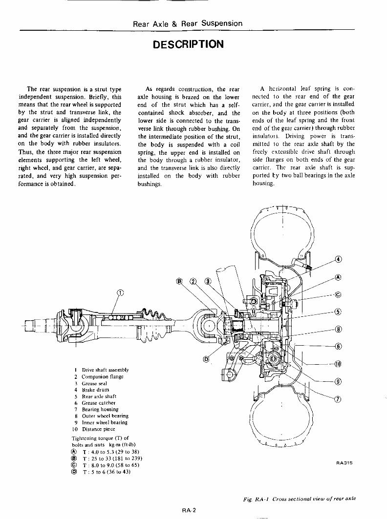
The rear suspension is a strut type independent suspension. Briefly, this means that the rear wheel is supported by the strut and transverse link, the gear carrier is aligned independently and separately from the suspension, and the gear carrier is installed directly on the body with rubber insulators, Thus, the three major rear suspension elements supporting the left wheel, right wheel, and gear carrier, are sepa- rated, and very high suspension per- formance is obtained.
D ESCR l PTl ON
As regards construction, the rear axle housing is brazed on the lower end of the strut which has a self- contained shock absorber, and the lower side is connected to the trans- verse link through rubber bushing. On the intermediate position of the strut, the body is suspended with a coil spring, the upper end is installed on the body through a rubber insulator, and the transverse link is also directly installed on the body with rubber bushings.
1 I
I Drive shaft assembly 2 Companion flanre
A hcrizontal leaf spring is con- nected lo the rear end of the gear carrier, and the gear carrier is installed on the t d y a t three positions (both ends of the leaf spring and the front end of the gear carrier) through rubber insulatols. Driving power is trans- mitted i o the rear axle shaft by the freely extensible drive shaft through side tlarges on both ends of the gear carrier. The rear axle shaft is sup- ported by two ball bearings in the axle housing.
3 Greasereal 4 Brakedrum 5 Rear axle shaft 6 Grease catcher 7 Bearing housing 8 Outer wheel bearing 9 Inner wheel bearing
10 Distance piece
Tightening larque (TI of bolls and nuts k g ~ m (fi-lb) @ @ @ @I T : 5 1 0 6 ( 3 6 1 0 4 3 )
T : 4.0 lo 5.3 (29 lo 38) T : 25 to 33 (181 lo 239) T : 8.0 lo 9.0 ( 5 8 10 65) RA315
Fig. RA-I (!ross sectional view of reor oxle
RA-2
-~
Rear Axle & Rear Suspension
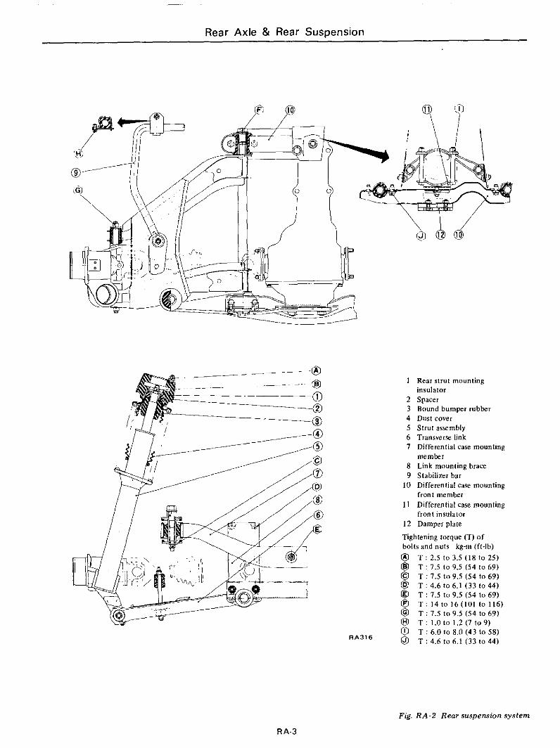
1 Rear strul mounting
2 Spacer 3 Bound bumper rubbcr 4 Dust cover 5 Strut assembly 6 Transverse link 7 Differential case mounting
8 Link mounting brace 9 Stabilizer bar
front member
front insulator
insulator
member
10 Differential case mounting
1 I Differential case mounling
1 2 Damper plate
Tightening torque (T) o f bolls and nuls kg-m (It-lb) @ @ @ @ @ @ @
0 @
T : 2.5 to 3.5 (18 to 2 5 ) T : 7.5 lo 9.5 (54 l o 6 9 ) T : 7.5 to 9.5 (54 to 69) T : 4.6 lo 6.1 (33 lo 44) T : 7.5 to 9.5 (54 lo 69) T : 1410 16(101 l o 116) T : 7.5 to 9.5 (54 to 69)
T : 6.0 lo 8.0 (43 lo 58) T : 4.6 to 6.1 (33 to 44)
0 T : 1.0 IO 1 . 2 (7 IO 9)
R A 3 1 6
Fig. R A - 2 Rear suspension system
RA-3
~ ~~
Rear Axle .& Rear Suspension
REAR AXLE
CONTENTS
WHEEL BEARING. OIL SEAL AND DRIVE SHAFT .
REMOVAL . . . . . . . . . . . . . . . . . . . . . . . . . . . . . RA-4 DISASSEMBLY
INSTALLATION . . . . . . . . . . . . . . . . . . . . . . . . . RA-4 ASSEMBLY.. . INSTRUCTIONS FOR ASSEMBLY OF
REAR AXLE SHAFT . . . . . . . . . . . . . . . . . . . . . . R A ~ 4 REMOVAL . . .
INSPECTION INSPECTION . . . . . . . . . . . . . . . . . . . . . . . . . . . RA-4
REAR WHEEL BEARING
WHEEL BEARING, OIL SEAL AND REAR AXLE SHAFT
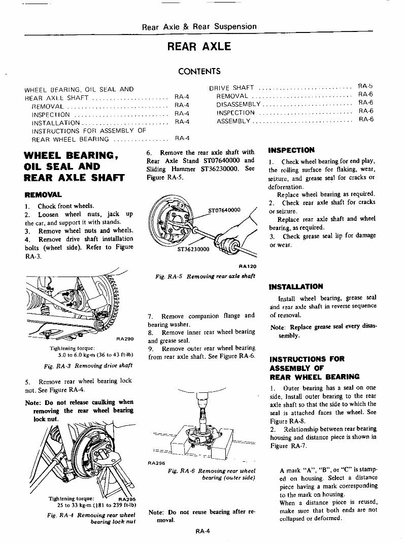
REMOVAL I . Chock front wheels. 2. Loosen wheel nuts, jack up the car, and support it with stands. 3. Remove wheel nuts and wheels. 4. Remove drive shaft installation bolts (wheel side). Refer t o Figure RA-3.
Tightening torque: 5.0 to 6.0 kg-m (36 to 43 ft-lb)
Fig. RA-3 Removing drive shaft
Remove rear wheel bearing lock 5. nut. See Figure RA-4.
Note: Do not release caulking when removing the IWU wheel bearing - lock nut.
Tightening torque: 25 to 33 kg-rn ( I 8 1 to 239 It-lb)
Fig. RA-4 Removing rear wheel bearing lock nut
. . . . . HA-4
6. Remove the rear axle shaft with Rear Axle Stand ST07640000 and Sliding Hammer ST36230000. See Figure RA-5.
R A l 2 O
Fig. RA-5 Removing rear axle shaft
7. Remove companion flange and bearing washer. 8. Remove inner rear wheel bearing and grease seal. 9. Remove outer rear wheel bearing from rear axle shaft. See Figure RA-6.
-. - RA296
Fig. RA-6 Removing reor wheel bearing (outer side)
Note: Do not reuse bearing after r e m o d .
RA-4
. . . . . . . . . . . . . . . . . . . . . . . . . . HA-5 . . . . . . . . . . . . . . . . . . . . . . . . . HA-6 . . . . . . . . . . . . . . . . . . . . . . . . . RA-6 . . . . . . . . . . . . . . . . . . . . . . . . . HA-6 . . . . . . . . . . . . . . . . . . . . . . . . . HA-6
INSPECTION I . Check wheel bearing for end play, the rolling surface for flaking, wear, seizure, and grease seal for cracks Or deformation.
Replace wheel bearing as required. 2. C:heck rear axle shaft for cracks or seiimre.
Replace rear axle shaft and wheel bearing, as required. 3. Check grease seal lip for damage or wear.
INSlALLATION Install wheel bearing, grease sed
and rear axle shaft in reverse sequence of removal.
Note: Replace grease seal every disas- sembly.
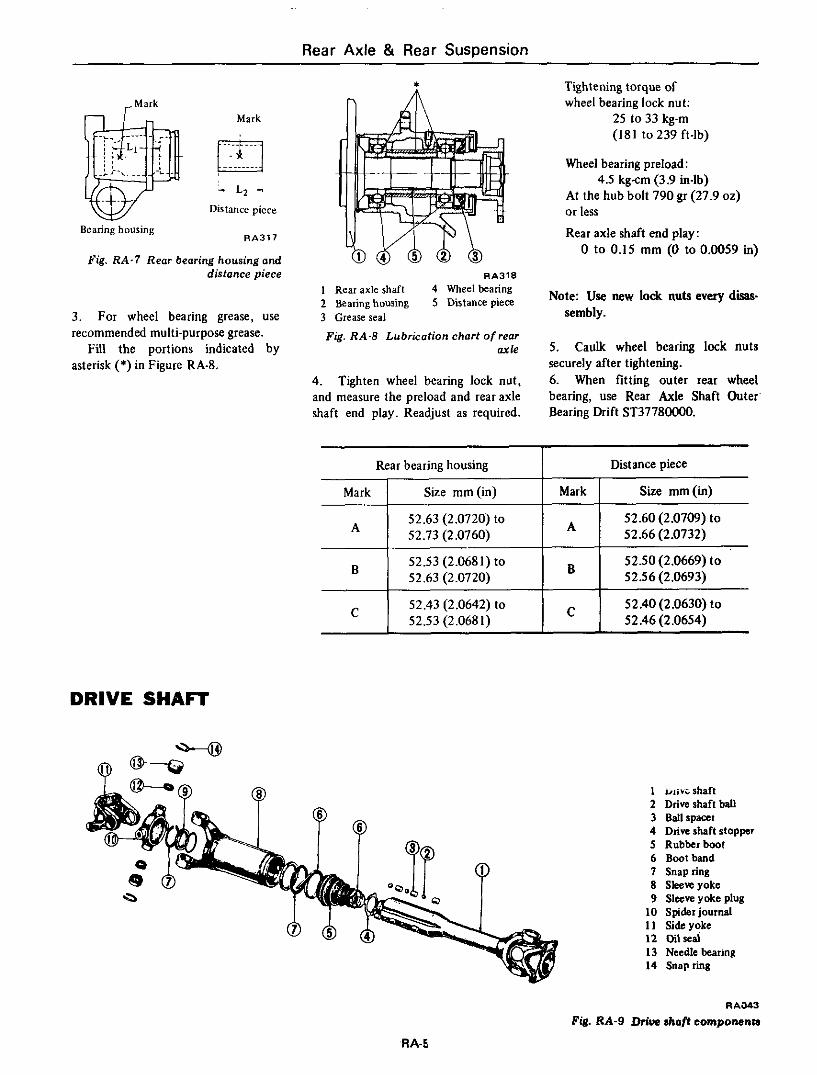
INSXRUCTIONS FOR ASSEMBLY OF REAR WHEEL BEARING 1. Outer bearing has a seal on one side. Install outer bearing to the rear axle shaft so that the side to which the seal is attached faces the wheel. See Figure RA-8. 2. Relationship between rear bearing housing and distance piece is shown in Figure RA-7.
A mark “A”, “ B , or “C” is Stamp- ed on housing. Select a distance piece having a mark corresponding to the mark on housing. When a distance piece is reused, make sure that both ends are not collapsed or deformed.
Rear Axle & Rear Suspension
Rear bearing housing
.Mark
Distance piece
Mark
.... .~. m ~. .. . . . .
- L* - Distance piece
A
B
C
Bearing housing RA317
52.60 (2.0709) to 52.66 (2.0732)
52.50 (2.0669) t o 52.56 (2.0693)
52.40 (2.0630) t o C 52.46 (2.0654)
A 52.63 (2.0720) to 52.73 (2.0760)
52.53 (2.0681) to 52.63 (2.0720)
52.43 (2.0642) to 52.53 (2.0681)
.
B
Fig. RA.7 Rear bearing housing and distance piece
3. For wheel bearing grease, use recommended multi-purpose grease.
Fill the portions indicated by asterisk (*) in Figure RA-8.
Tightening torque of wheel bearing lock nut:
25 to 33 kg-m (181 to239 ft-lb)
Wheel bearing preload: 4.5 kg-cm (3.9 in-lb)
At the hub bolt 790 gr (27.9 02)
or less
Rear axle shaft end play: 0 to 0.15 mm (0 to 0.0059 in)
HA318
I Rear axle shaft 4 Wheel bearing 2 Bearing housing 5 Distance piece 3 Greare seal
Fig. RA-8 Lubricotion chart of rear ax le
4. Tighten wheel bearing lock nut, and measure the preload and rear axle shaft end play. Readjust as required.
Note: Use new lock nuts every disae sembly.
5. Caulk wheel bearing lock nuts securely after tightening. 6. When fitting outer rear wheel bearing, use Rear Axle Shaft Outer Bearing Drift ST37780000.
DRIVE SHAFT
1 u i i r~shaf t 2 Driveshaft ball 3 Ballspaat 4 Dive shaft stopper 5 Rubberboot 6 Bootband 7 Snapring 8 Skeveyoke 9 Sleeve yoke plug
10 Spider journal I 1 Side yoke 12 oilseal 13 Needle bearing 14 Snapring
RA-3
Fig. RA-9 Drius ahoft compomnta
RA-5
Rear Axle i3 Rear Suspension
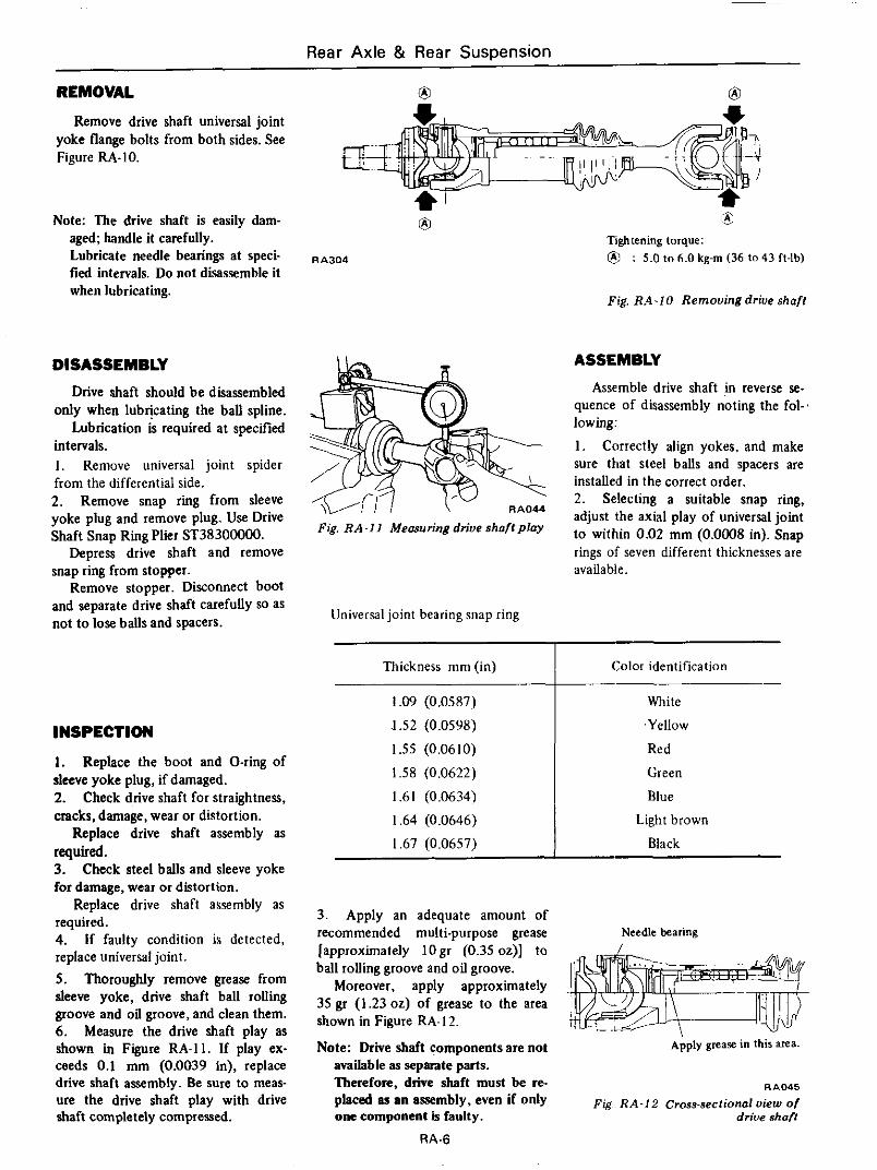
REMOVAL 0 Remove drive shaft universal joint
yoke flange bolts from both sides. See Figure RA- IO.
Note: The drive shaft is easily dam- aged; handle it carefully. Lubricate needle bearings at speci- fied intervals. Do not disassemble it when lubricating.
Tightening torque: @I RA304 : 5.0 to 6.0 kg-m (36 lo 43 fl-lb)
Fig. R.4-IO Remouingdriue shaft
Thickness mm (in)
1.09 (0.0587)
.I .52 (0.0598)
1.55 (0.0610)
1.58 (0.0622)
1.61 (0.0634)
I .64 (0.0646)
I .67 (0.0657)
DISASSEMBLY
Drive shaft should be disassembled only when lubricating the ball spline.
Lubrication h required at specified intervals. I . Remove universal joint spider from the differential side. 2. Remove snap ring from sleeve yoke plug and remove plug. Use Drive Shaft Snap Ring Plier ST38300000.
Depreu drive shaft and remove snap ring from stopper.
Remove stopper. Disconnect boot and separate drive shaft carefully so as not to lox balls and spacers.
Color identification
White
.Yellow
Red
Green
Blue
Light brown
Black
INSPECTION
1. Replace the boot and O-ring of sleeve yoke plug, if damaged. 2. Check drive shaft for straightness, cracks, damage, wear or distortion.
Replace drive shaft assembly as required. 3. Check steel balls and sleeve yoke for damage, wear or distortion.
Replace drive shaft assembly as required. 4. If faulty condition is detected, replace universal joint. 5 . Thoroughly remove grease from sleeve yoke, drive shaft ball rolling groove and oil groove, and clean them. 6. Measure the drive shaft play as shown in Figure RA-I I . If play ex-
ASSEMBLY
Assemble drive shaft in reverse se- quence of disassembly noting the fol-.
I . Correctly align yokes, and make sure that steel balls and spacers are installed in the correct order. 2. Selecting a suitable snap ring, adjust the axial play of universal joint to within 0.02 mm (0,0008 in), snap rings of seven different thicknesses are available.
lowing:
Fig. RA-II Meosuringdriueshaftploy
3. Apply an adequate amount of recommended multi-purpose grease [approximately lOgr (0.35 oz)] to ball rolling groove and oil groove.
Moreover, apply approximately 35 gr (1.23 02) of grease to the area shown in Figure RA- 12.
Note: Wive shaft components are not
Needle bearing
Apply grease in this area.
ceeds 0.1 mm (0.0039 in), replace
ure the drive shaft play with drive Fig R A - I 2 Cross-sectionof view of shaft completely compressed. one component is faulty. drive shaft
available as separate parts.
placed aa an assembly, even if only drive shaft assembly. Be sure to meas- Therefore, drive shaft must be re- RA045
RA-6
Rear Axle 81 Rear Suspension
REAR SUSPENSION
CONTENTS
REAR STRUT AND COIL SPRING . . . . . . . . . RA- 7 TRANSVERSE L I N K . , . . . . . . . . . . . . . . . . . . . . RA- 9 REMOVAL . . . . . . . . . . . . . . . . . . . . . . . . . . . . RA- 7 REMOVAL . . . . . . . . . . . . . . . . . . . . . . . . . . . . RA- 9 INSTALLATION.. . . . . . . . . . . . . . . . . . . . . . . RA- 8 INSPECTION . . . . . . . . . . . . . . . . . . . . . . . . . . RA-10
GEAR CARRIER AND DIFFERENTIAL INSTALLATION . . . . . . . . . . . . . . . . . . . . . . . . RA-10 MOUNTING MEMBER . . . . . . . . . . .
REMOVAL . . . . . . . . . . . . . . . . . . . INSPECTION . . . . . . . . . . . . . . . . . I NSTA L LAT I ON . . . . . . . . . . . . . . .
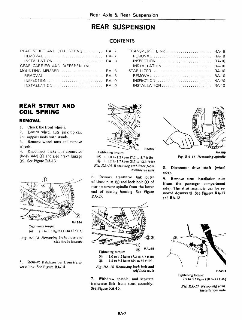
REAR STRUT AND COIL SPRING REMOVAL I . Chock the front wheels. 2. Loosen wheel nuts, jack up car, and support body with stands. 3. Remove wheel nuts and remove wheels. 4. Disconnect brake line connector (body side) @ and side brake linkage 0. See Figure RA-13.
Tightening forque:
@ : 1.5 to 1.8 kg-m ( I 1 to 13 fl-lb)
Fig. RA-13 Removing brake hose and side brake linkage
5. verse link. See Figure RA-14.
Remove stabilizer bar from trans-
. .
. . . . . . . R A ~ 8 STAB1 LIZ ER . . . . . . . . . . . . . . . . . . . . . . . . . . . . RA-1 0
. . . . . . . RA- 8 REMOVAL . . . . . . . . . . . . . . . . . . . . . . . . . . . . RA-10
. . . . . . . RA- 9 INSPECTION . . . . . . . . . . . . . . . . . . . . . . . . . . RA-IO
. . . . . . . RA- 9 INSTALLATION . . . . . . . . . . . . . . . . . . . . . . . . RA-10
RAZE7 Tightening torque: @ @
: 1.0 lo 1.2 kg-m (7.2 to 8.7 ft-lb) : 1.2 to 1.7 kg-m (8.7 lo 12.3 ft4b)
Fig. RA-14 Removing stabilizer from tronsverse link
6. Remove transverse link outer self-lock nuts 0 and lock bolt @ of rear transverse spindle from the lower end of bearing housing. See Figure RA-15.
@ RA288 Tightening torque: @ : 1.0 to 1.2 kg-m (7.2 to 8.7 ft-lb) @ : 7.5 to 9.5 kg-m (54 to 69 ft-lb)
Fig. RA-15 Removing lock bolt and self-loek nuts
7. Withdraw spindle, and separate transverse link from strut assembly. See Figure RA-16.
RA289 Fig. RA-16 Removing spindle
8. Disconnect drive shaft (wheel side). 9. Remove strut installation nuts (from the passenger compartment side). The strut assembly can be re- moved downward. See Figures RA-17 and RA-18.
RA291
2.5 to 3.5 kg-m (18 to 25 ft-lb)
Fig. RA-17 Removing strut installation nub
Tightening torque:
RA-7
Rear Axle & Rear Suspension
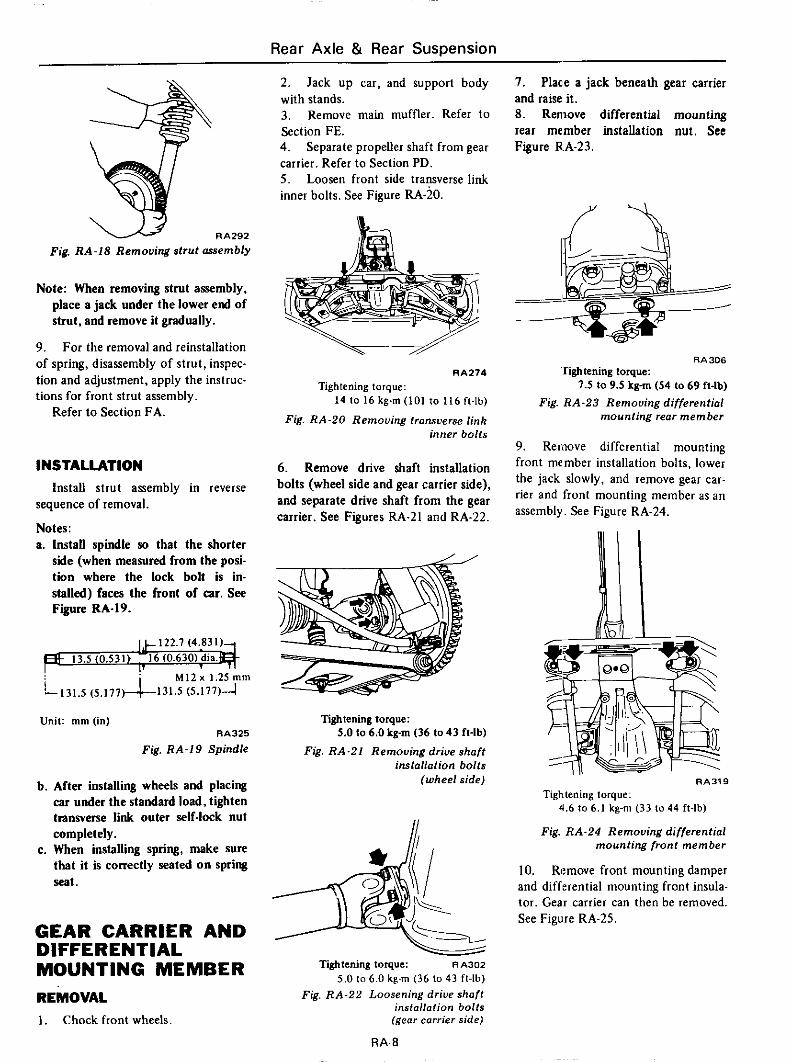
RA292
Fig. RA-18 Removing strut assembly
Note: When removing strut assembly, place a jack under the lower end of strut, and remove it gradually.
9. For the removal and reinstallation of spring, disassembly of strut, inspec- tion and adjustment, apply the instruc- tions for front strut assembly.
Refer to Section FA.
INSTALLATION
sequence of removal.
Notes: a. Install spindle so that the shorter
side (when measured from the posi- tion where the lock bolt is in- stalled) faces the front of car. See
Install strut assembly in reverse
Figure RA-19.
13.5 (0.531) . 16 (0.630) dia. M I 2 x 1.25 m m
i l 3 l . 5 (5.177)-&-13L.5 (5.177)J
Unit: mrn (in) RA325
Fig. RA-19 Spindle
b. After installing wheels and placing car under the standard load, tighten transverse link outer self-lock nut completely.
c. When installing spring, make sure that it is correctly seated on spring seat.
GEAR CARRIER AND DIFFERENTIAL MOUNTING MEMBER REMOVAL 1. Chock front wheels.
2. with stands. 3. Section FE. 4. carrier. Refer to Section PD. 5 . inner bolts. See Figure RA-20.
Jack up car, and support body
Remove main muffler. Refer to
Separate propeller shaft from gear
Loosen front side transverse link
~ ~ 2 7 4
141016kg-m( l0 l lo116f l - lb )
Fig. RA-20 Remooing transverse link inner bolts
Tightening torque:
6. Remove drive shaft installation bolts (wheel side and gear carrier side), and separate drive shaft from the gear carrier. See Figures RA-21 and RA-22.
Tightening torque: 5.0 lo 6.0 kg-m (36 to 43 It-lb)
Fig. RA-21 Removing drive shaft instnllntion bolts
(wheel side)
Tiitening torque: RA302
5.0 to 6.0 kg-m (36 lo 43 fl-lb) Fig. RA-22 Loosening drive shaft
instollation bolts (gew corrier side)
RA-8
7. P1ac.e a jack beneath gear carrier and raise it. 8. Remove differential mounting rear member installation nut. See Figure RA-23.
RA306 'Tightening torque:
7.5 to 9.5 kgm (54 to 69 fl-lb)
Fig. RA-23 Remouing differentinl mounting rear member
9. Remove differential mounting front member installation bolts, lower the jack slowly, and remove gear car- rier and front mounting member as an assembly. See Figure RA-24.
. I. RA319
Tightening torque: 4.6 lo 6.1 kg-m (33 to 44 fl-lb)
Fig. RA-24 Removing differentinl mounting front member
IO. Rmove front mounting damper and differential mounting front insula- tor. Gear carrier can then be removed. See Figure RA-25.
Rear Axle & Rear Suspension
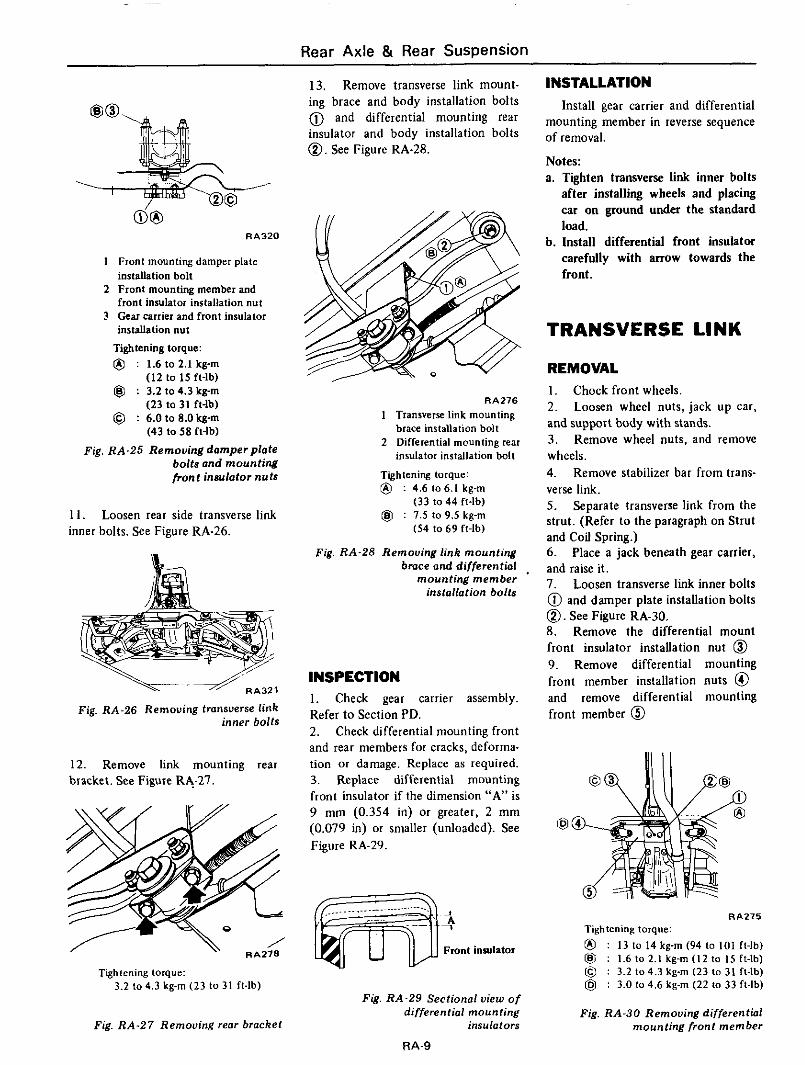
do RA320
1 Front mounting damper plate installation bolt
2 Front mounting member and front insulator installation nut
3 Gear Farrier and front insulatoi installation nut
Tightening torque: @ : 1.6 to 2.1 kg-m
(12 to 15 ft-lb) @ : 3.2 lo 4.3 kg-m
(23 to 31 ft-lb) I@ : 6.0 to 8.0 kg-m
(43 to 58 ft-lb) Fig. RA-25 Removing damperplate
bolts and mounting front insulator nuts
11. inner bolts. See Figure RA-26.
Loosen rear side transverse link
Fig. RA-26 Removing transverse link inner bolts
12. Remove link mounting rear bracket. See Figure RA27.
Tightening torque: 3.2 to 4.3 kg-m (23 lo 31 ft-lb)
Fig. RA-27 Removing rear bracket
13. Remove transverse link mount- ing brace and body installation bolts @ and differential mounting rear insulator and body installation bolts 0. See Figure RA-28.
RA276
1 Transverse link mounting brace installation bolt
2 Differential mounting rear insulator installation bolt
Tightening torque: @ : 4.6 lo 6.1 kg-m
(33 to 44 ft-lb) @ : 1.5 to 9.5 kg-m
(54 10 69 ft-lb)
Fig. RA-28 Removing link mounting brace and differential .
mounting member installation bolts
INSPECTION 1. Check gear carrier assembly. Refer to Section PD. 2. Check differential mounting front and rear members for cracks, deforma- tion or damage. Replace as required. 3. Replace differential mounting front insulator if the dimension “A” is 9 mm (0.354 in) or greater, 2 mm (0.079 in) or smaller (unloaded). See Figure RA-29.
3
1 A
Front insulator
Fig. RA-29 Sectional view o f different id mounting
insulators
RA-9
INSTALLATION Install gear carrier and differential
mounting member in reverse sequence of removal.
Notes: a. Tighten transverse link inner bolts
after installing wheels and placing car on ground under the standard load.
b. Install differential front insulator carefully with arrow towards the front.
TRANSVERSE LINK
REMOVAL 1. Chock front wheels. 2. Loosen wheel nuts, jack up car, and support body with stands. 3. Remove wheel nuts, and remove wheels. 4. Remove stabilizer bar from trans- verse link. 5 . Separate transverse link from the strut. (Refer to the paragraph on Strut and Coil Spring.) 6. Place a jack beneath gear carrier, and raise it. 7. Loosen transverse link inner bolts @ and damper plate installation bolts 0. See Figure RA-30. 8. Remove the differential mount front insulator instauation nut 0 9. Remove differential mounting front member installation nuts @ and remove differential mounting front member @
RA275 Tightening torque: @ : 13 lo 14 kg-rn (94 l o 101 ft-lb) @J : 1.6 to 2.1 kg-m ( I2 to I S ft-lb) @ : 3.2 104.3 kg-m (23 lo 31 ft-lb) @ : 3.0 lo 4.6 kg-m (22 to 33 ft-lb)
Fig. RA-30 Removing differential mounting front member
Rear Axle & Rear Suspension
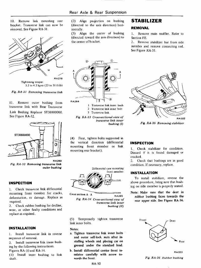
IO. Remove link mounting rear bracket. Transverse link can now be removed. See Figure RA-31.
RA278
Tightening torque: 3.2 104.3 kg-m (23 to 31 ft-lb)
Fig. RA-31 Removing transverse link
11. Remove outer bushing from transverse link with Rear Transverse
Link Bushing Replacer ST38800000. See Figure RA-32.
RA280
Fig. RA-32 Removing tmnsuerse link outer bushing
INSPECTION 1. Check transverse link differential mounting front member for clacks, deformation, or daniage. Replace as required. 2. Check rubber bushing for decline, wear, or other faulty conditions and replace as required.
INSTALLATION 1. Install transveise link in reverse sequence of removal. 2. Install transverse link inner bush- ing by the following instructions. Figures RA-33 and RA-34. ( I ) Install inner bushing to link shaft.
(2) Align projection on bushing (directed to the axis direction) hori- zontally. (3) Align the center of bushing (directed toward the axis direction) to the center of bracket.
STAlBlLlZER REMOlVAL 1. Remove main muffler. Refer to Section FE. 2. Remove stabilizer bar from side membei and remove connecting rod. See Figure RA-35.
I Transverse link inner bush 2 Transverse link inner bolt 3 Transverse link
Fig. RA-33 Cross-sectional uiew of transuerse link inner
bushing ( I )
(4) First, tighten bolts supported in the vertical direction (differential mounting front member or link mounting rear bracket).
Differential case mounting
u RA285 cross secfion A-A
Fig. RA-34 Cross-sectional uiew of transuerse link inner
bushing ( I I )
(5) Temporarily tighten transverse link inner bolts.
Notes: a. Tighten tranwerse link inner bolts
and outer self-lock nuts after in- stalling wheels and placing car on ground under the standard load.
b. Install differential carrier front in- sulator carefully with arrow to- wards the front.
RA-IO
RA322
Pig. RA-35 Removing stabilizer
INSPECTION I . , Check stabilizer for condition. Discard if it is found damaged or cracked. 2. Check that bushings are in good condition. If necessary, replace.
INSTALLATION To install stabilizer, reverse the
above procedure, being sure that bush- ing on side member is properly seated.
Note: Make sure that the dent in rubber bushing faces towards the rear upper side. See Figure RA-36.
RA323
Fig. XA-36 Rubber bushing
Rear Axle & Rear Suspension
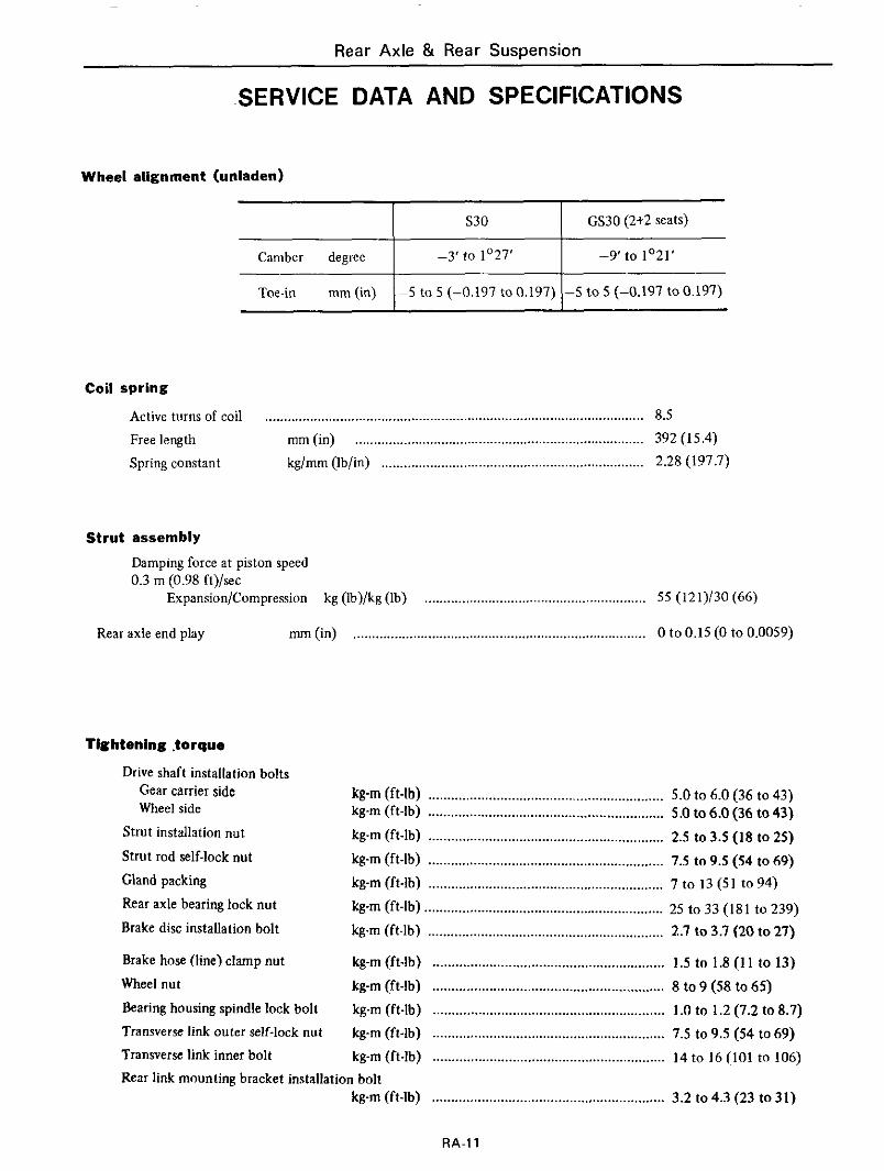
S30
SERVICE DATA AND SPECIFICATIONS
GS30 (2t2 seats) ~ ~ ~~~
Camber degree -3' to 1'27'
Toe-in mm (in) -5 to 5 (-0.197 to 0.197)
-9 ' to 1'21'
-5 to 5 (-0.197 to 0.197)
Coil spring
Active turns of coil ..................................................................................................... 8.5 Free length mm(in) ............................................................................. 392 (15.4) Spring constant kg/mm (Ib/in) ...................................................................... 2.28 (197.7)
Strut assembly
Damping force at piston speed 0.3 m (0.98 ft)/sec
Expansion/Compression kg (Ib)/kg (Ib) ........................................................... 5 5 (121)/30 (66)
Rear axle end play mm (in) .............................................................................. 0 to 0.15 (0 to 0.0059)
Tightening .torquo
Drive shaft installation bolts Gear carrier side Wheel side
Strut installation nut
Strut rod self-lock nut
Gland packing Rear axle bearing lock nut
Brake disc installation bolt
Brake hose (line) clamp nut
Wheel nut
Bearing housing spindle lock bolt Transverse link outer self-lock nut
Transverse link inner bolt
kg-m (ft-lb) ...................................... .................... 5.0 to 6.0 (36 to 43) kg-m (ft-lb) .............................................................. 5.0 to 6.0 (36 to 43)
k g m (ft-lb) .............................................................. 2.5 to 3.5 (18 to 25)
kg-m (ft-lb) ...................... ................................... 7.5 to 9.5 (54 to 69) k g m (ft-lb) ...................... kg-m (ft-lb) ............................................................... 25 to 33 (181 to 239)
kgm (ft-lb) ......................... ............................... 2.7 to 3.7 (20 to 27)
kg-m (ft-lb) ............................................................. 1.5 to 1.8 (1 1 to 13)
kg-m (ft-lb) ............................................................. 1.0 to 1.2 (7.2 to 8.7) kg-m (ft-lb) ............................................................. 7.5 to 9.5 (54 to 69) kg-m fft-lb) ............................................................. 14 to 16 (101 to 106)
............ 7 t o 13 (51 to 94)
kg-m (ft-lb) ............................................................. 8 to 9 (58 to 65)
Rear link mounting bracket installation bolt kg-m (ft-lb) ............................................................. 3.2 to 4.3 (23 t o 31)
RA-11
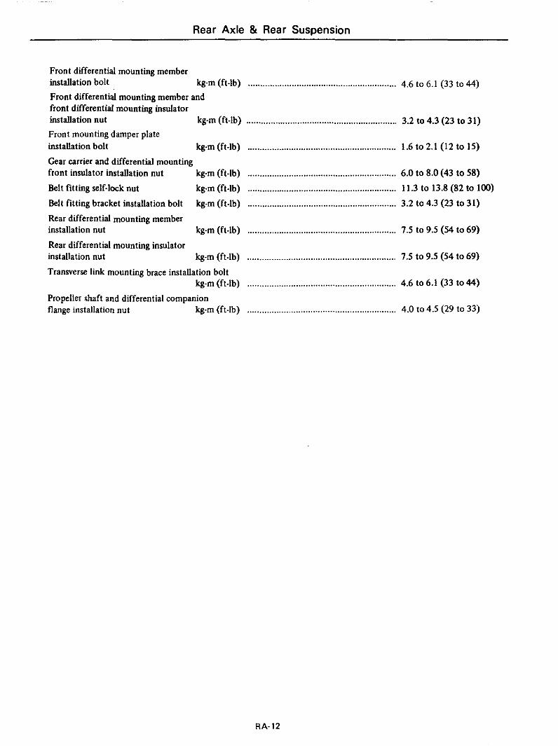
Rear Axle & Rear Suspension
Front differential mounting member
Front differential mounting member and front differential mounting insulator installation nut Front mounting damper plate installation bolt
Gear carrier and differential mounting front insulator installation nut
Belt fitting self-lock nut
Belt fitting bracket installation bolt Rear differential mounting member installation nut
Rear differential mounting insulator installation nut
Transverse link mounting brace installation bolt
Propeller shaft and differential companion flange installation nut
installation bolt kg-m (ft-lb) ............................................................. 4.6 to 6.1 (33 to 44)
kg-m (ft-lb) .............................................................. 3.2 to 4.3 (23 to 31)
kg-m (ft-lb) ............................................................. 1.6 to 2.1 (12 to IS)
kg-m (ft-lb) ............................................................. 6.0 to 8.0 (43 to 58) kg-m (ft-lb) ............................................................. 11.3 to 13.8 (82 to 100)
kg-m (ft-lb) ............................................................. 3.2 to 4.3 (23 to 31)
kg-m (ft-lb) ............................................................. 7.5 to 9.5 (54 to 69)
kg-m (ft-lb) ............................................................. 7.5 to 9.5 (54 to 69)
kg-m (ft-lb) ............................................................. 4.6 to 6.1 (33 to 44)
kg-m (ft-lb) ............................................................. 4.0 to 4.5 (29 to 33)
RA-12
Rear Axle & Rear Suspension
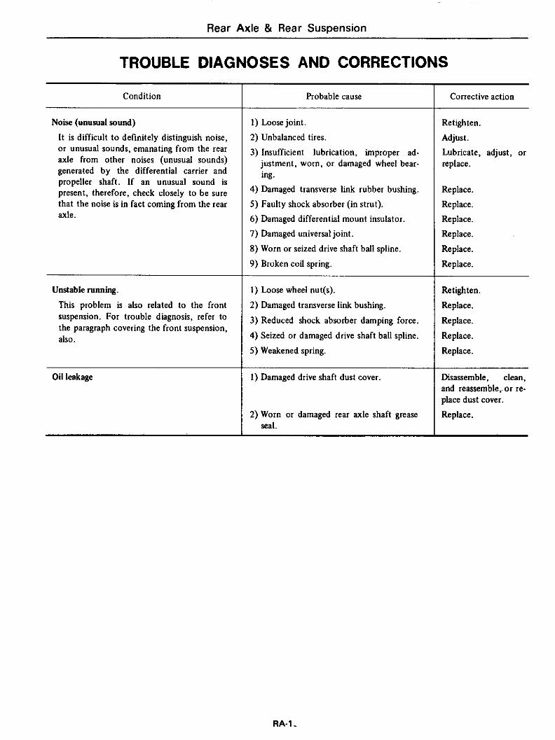
TROUBLE DIAGNOSES AND CORRECTIONS
Condition
Noise (unusual sound)
It is difficult t o definitely distinguish noise, or unusual sounds, emanating from the rear axle from other noises (unusual sounds) generated by the differential carrier and propeller shaft. If an unusual sound is present, therefore, check closely to be sure that the noise is in fact coming from the rear axle.
Unstable running.
This problem is also related to the front suspension. For trouble diagnosis, refer to the paragraph covering the front suspension, also.
Oil leakage
Probable cause
1) Loose joint.
2) Unbalanced tires.
3) Insufficient lubrication, improper ad- justment, worn, or damaged wheel bear- ing.
4) Damaged transverse link rubber bushing. 5) Faulty shock absorber (in strut). 6) Damaged differential mount insulator. 7) Damaged universal joint.
8) Worn or seized drive shaft ball spline.
9) Broken coil spring.
I ) Loose wheel nut(s).
2) Damaged transverse link bushing.
3) Reduced shock absorber damping force.
4) Seized or damaged drive shaft ball spline.
5) Weakened spring.
1) Damaged drive shaft dust cover
2) Worn or damaged rear axle shaft grease seal.
Corrective action
Retlghten. Adjust. Lubricate, adjust, or replace.
Replace. Replace. Replace. Replace.
Replace.
Replace.
Retighten.
Replace.
Replace.
Replace.
Replace.
Disassemble, clean, and reassemble,. or re- place dust cover.
Replace.
RA-1-
Rear Axle i3 Rear Suspension
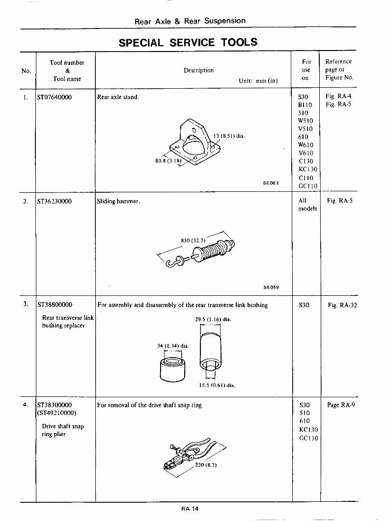
SPECIAL SERVICE TOOLS - NO.
L.
- 3.
-
4.
-
Tool number &
Tool name
r36230000
T38800000
Rear transverse lin bushing replacer
r3a300000 iT492 10000)
Drive shaft snap ring plier
Description
Unit: mm (in)
lear axle stand.
SE063
iliding hammer.
830
6 ?.E059
:or assembly and disassembly of the rear transverse link bushing
29.5 (1.16) dia.
3 34 (1.34) dia.
15.5 (0.61)dia
;or removal of the drive shaft snap ring
For use on - S30 B l l O SI0 WSlO VSIO 610 W 6 1 0 V610 C130 KC13C C l l O CCI 1c
All modelr
S30
S30 510 610 KC l3( GCI I (
Reference page or Figure No.
Fig. RA-4 Fig. RA-5
Fig. RA-5
Fig. RA-32
Page RA-9
RA-14
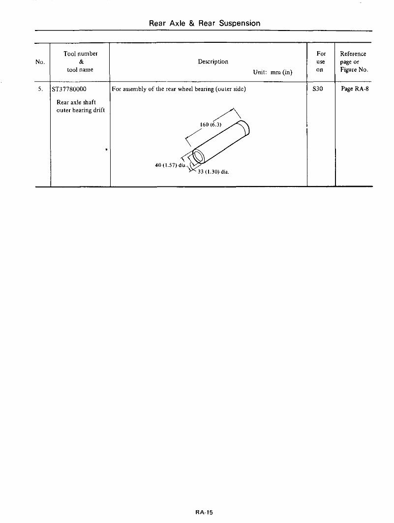
Rear Axle & Rear Suspension
Tool number &
tool name Description
Unit: mm (in)
,T37780000
Rear axle shaft outer bearing drift
I For assembly of the rear wheel bearing (outer side)
- For use on
S30
Reference page or Figure No.
Page RA-8
RA-15
509 Debby Lane Adamsville, AL 35005 http://www.zcarcreations.com [email protected]
NISSAN FACTORY SERVICE MANUAL CDROM END-USER LICENSE AGREEMENT NOTICE TO USER: THIS IS A CONTRACT. BY PURCHASING AND USING THE SERVICE MANUAL ON CDROM, YOU ACCEPT ALL THE TERMS AND CONDITIONS OF THIS AGREEMENT. This End User License Agreement accompanies the Service Manual on CDROM product and related explanatory materials. Please read this Agreement carefully. By purchasing and using the Service Manual on CDROM, you are implying that you have carefully read, agree with, and will adhere to the conditions set forth in this agreement. If you do not wish to accept the terms of this End User Agreement please do not use the Service Manual on CDROM. You will not be permitted to use the Service Manual on CDROM without consenting to this end user agreement. Upon your acceptance of this Agreement, Z Car Creations, LLC grants to you a nonexclusive license to use the Service Manual on CDROM, provided that you agree to the following: USE OF SOFTWARE You may install the contents of the CD on a hard disk or other storage device for personal use only. Each Service Manual on CDROM comes with a single user license. Under no circumstances should the contents of the Service Manual CDROM be placed on a server for purposes of distributing or allowing access to the material over a network. COPYRIGHT AND TRADEMARK RIGHTS The Service Manual CDROM is owned by Z Car Creations, LLC and its structure and organization, all graphics and coding are considered intellectual property of Z Car Creations, LLC. The manual content itself is property of Nissan Motors. The Service Manual on CDROM is also protected by United States Copyright Law and International Treaty provisions. This Agreement does not grant you any intellectual property or resale rights to the Service Manual CDROM. RESTRICTIONS You agree not to modify, adapt, translate, reverse engineer, decompile or disassemble the PDF file on the Service Manual CDROM. The Service Manual on CDROM is licensed and distributed by Z Car Creations, LLC for single user utilization of its contents only. Licensed users will be permitted to use the contents of the Service Manual CDROM for multimedia presentation to an audience from a single machine using a large display or projection device but the Service Manual CDROM may not otherwise be distributed, sold to or made accessible to multiple users. NO WARRANTY The software is being delivered to you AS IS and Z Car Creations, LLC makes no warranty as to its use or performance. Z CAR CREATIONS, LLC DOES NOT AND CANNOT WARRANT THE PERFORMANCE OR RESULTS YOU MAY OBTAIN BY USING THE SERVICE MANUAL CDROM OR DOCUMENTATION, NOR MAKES ANY WARRANTIES, EXPRESS OR IMPLIED, AS TO NONINFRINGEMENT OF THIRD-PARTY RIGHTS, MERCHANTABILITY, OR FITNESS FOR ANY PARTICULAR PURPOSE. IN NO EVENT WILL Z CAR CREATIONS, LLC BE LIABLE TO YOU FOR ANY CONSEQUENTIAL, INCIDENTAL, OR SPECIAL DAMAGES FOR ANY REASON.
509 Debby Lane Adamsville, AL 35005 http://www.zcarcreations.com [email protected]
GOVERNING LAW AND GENERAL PROVISIONS This Agreement will be governed by the laws of the State of Alabama, USA, excluding the application of its conflicts of law rules. This Agreement will not be governed by the United Nations Convention on Contracts for the International Sale of Goods, the application of which is expressly excluded. If any part of this Agreement is found void and unenforceable, it will not affect the validity of the balance of the Agreement, which shall remain valid and enforceable according to its terms. You agree that the Service Manual on CDROM will not be shipped, transferred or exported into any country or used in any manner prohibited by the United States Export Administration act or any other export laws, restrictions or regulations. This Agreement shall automatically terminate upon failure by you to comply with its terms. This Agreement may only be modified in writing signed by and authorized officer for Z Car Creations, LLC. Craig Borden Z Car Creations, LLC 509 Debby Lane Adamsville, AL 35005 USA YOUR ACCEPTANCE OF THE FOREGOING AGREEMENT IS IMPLIED UPON PURCHASING AND USING THE SERVICE MANUAL CDROM.