Embed Size (px)
Citation preview
Disassembly and Assembly of Differential (with out A.D.D.)
–SUSPENSION AND AXLE Front Differential (Disassembly and Assembly ofDifferential w/o A D D )
SA–66
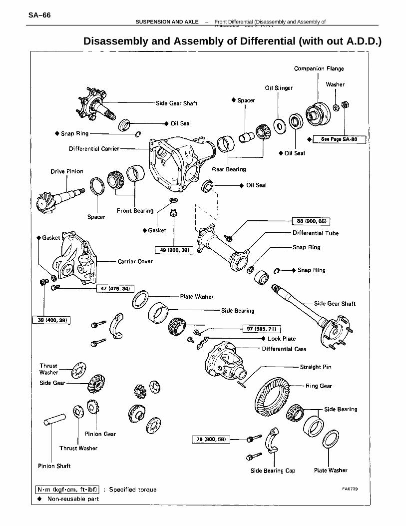
2. CHECK SIDE GEAR BACKLASHMeasure the side gear backlash while holding one piniongear toward the case.Standard backlash: 0.05 – 0.20 mm
(0.0020 – 0.0079 in.)
If the backlash is out of specification, install the correctthrust washers. (See page SA–71 )
3. REMOVE SIDE GEAR SHAFTSUsing SST, remove the side gear shafts from the differ–ential.SST 09910–00015 .
(09911–00011, 09912–00010, 09914–00011)
DISASSEMBLY OF DIFFERENTIAL1. REMOVE DIFFERENTIAL COVER
Remove the eight bolts and tap off the cover with aplastic–faced hammer.
4. REMOVE DIFFERENTIAL TUBERemove the four bolts and tap off the cover with aplastic–faced hammer.
5. REMOVE SIDE GEAR SHAFT OIL SEALSUsing SST, remove the oil seals.SST 09308–00010
–SUSPENSION AND AXLE Front Differential (Disassembly and Assembly ofDifferential w/o A D D )
SA–67
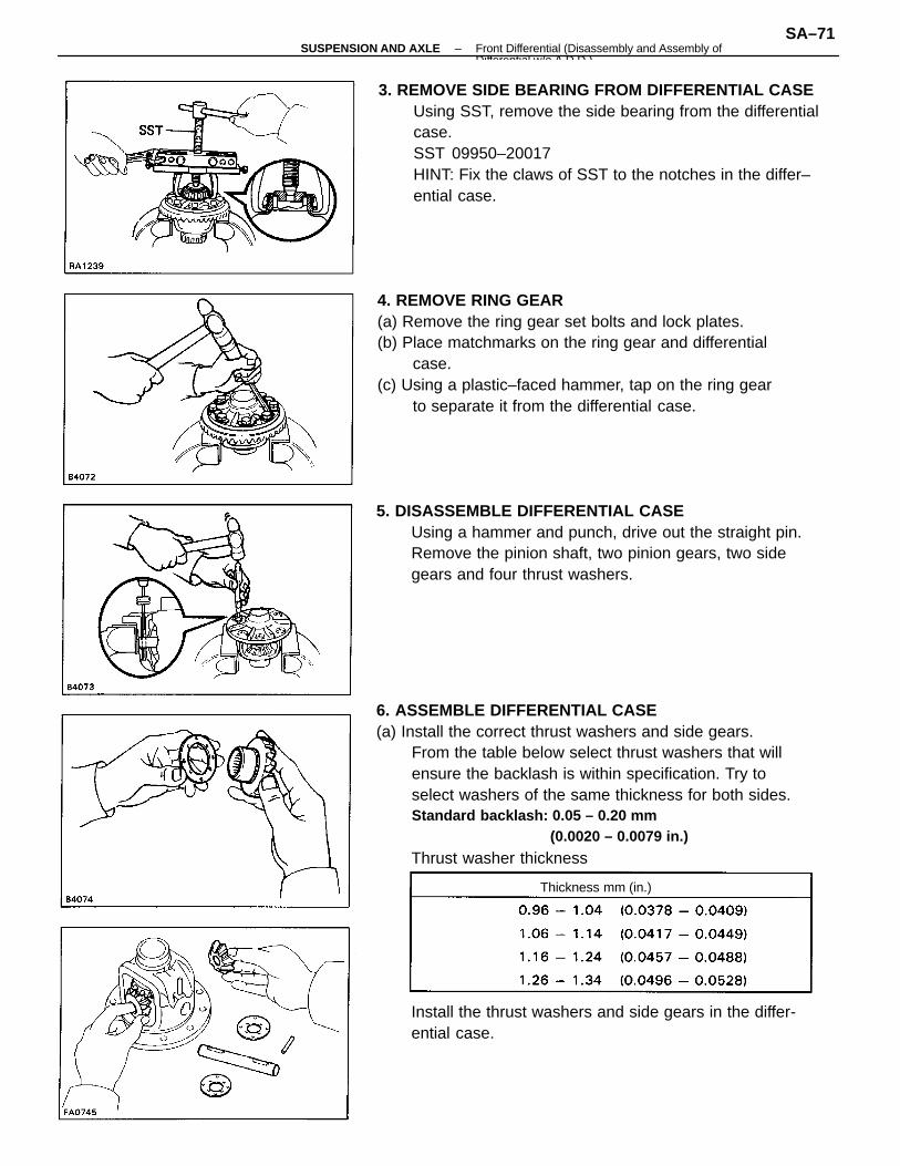
9. MEASURE DRIVE PINION PRELOADUsing a torque gauge, measure the preload of the back–lash between the drive pinion and ring gear.Preload (starting):
0.6 – 1.0 N–m (6 – 10 kgf–cm, 5.2 – 8.7 in.–lbf)
10. CHECK TOTAL PRELOADUsing a torque gauge, measure the total preload.Total preload (starting):
Add drive pinion preload0.4 – 0.6 N–m(4 – 6 kgf –cm, 3.5 – 5.2 in.–Ibf)
11. REMOVE COMPANION FLANGE(a) Using a hammer and chisel, loosen the staked part
of the nut.
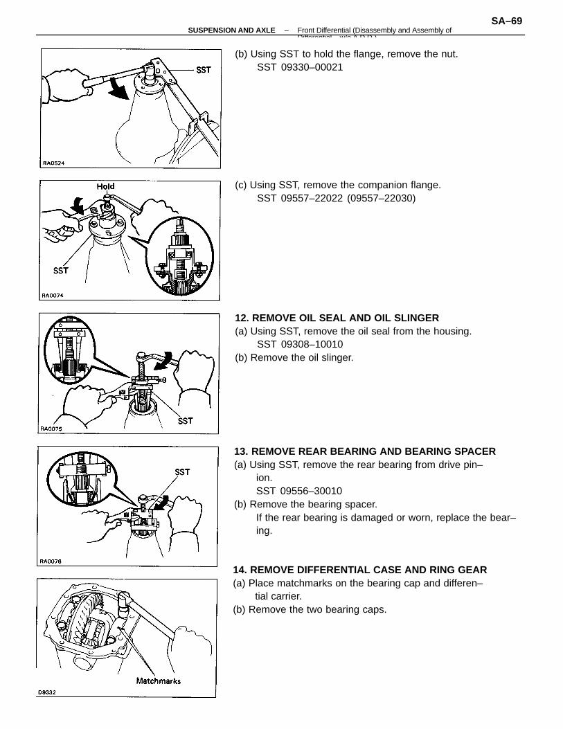
7. CHECK RING GEAR BACKLASH(a) Fix the dial indicator on the tooth surface at a 90�
angle.(b) Holding the drive pinion flange, measure the ring
gear backlash.Ring gear backlash: 0.13 – 0.18 mm
(0.0051 – 0.0071 in.)
If the backlash is not within specification, adjust the ringgear backlash.HINT: Measure from three or more places on the cir–cumference of the ring gear.
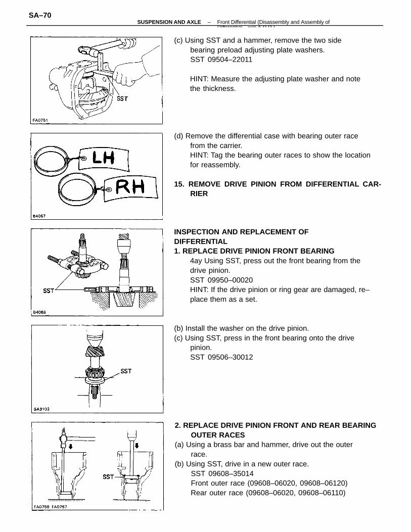
8. INSPECT TOOTH CONTACT BETWEEN RING GEAR ANDDRIVE PINION (SEE STEP 7 ON PAGE SA–78)
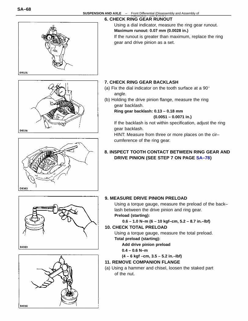
6. CHECK RING GEAR RUNOUTUsing a dial indicator, measure the ring gear runout.Maximum runout: 0.07 mm (0.0028 in.)
If the runout is greater than maximum, replace the ringgear and drive pinion as a set.
–SUSPENSION AND AXLE Front Differential (Disassembly and Assembly ofDifferential w/o A D D )
SA–68
13. REMOVE REAR BEARING AND BEARING SPACER(a) Using SST, remove the rear bearing from drive pin–
ion.SST 09556–30010
(b) Remove the bearing spacer.If the rear bearing is damaged or worn, replace the bear–ing.
14. REMOVE DIFFERENTIAL CASE AND RING GEAR(a) Place matchmarks on the bearing cap and differen–
tial carrier.(b) Remove the two bearing caps.
12. REMOVE OIL SEAL AND OIL SLINGER(a) Using SST, remove the oil seal from the housing.
SST 09308–10010(b) Remove the oil slinger.
(c) Using SST, remove the companion flange.SST 09557–22022 (09557–22030)
(b) Using SST to hold the flange, remove the nut.SST 09330–00021
–SUSPENSION AND AXLE Front Differential (Disassembly and Assembly ofDifferential w/o A D D )
SA–69
INSPECTION AND REPLACEMENT OFDIFFERENTIAL1. REPLACE DRIVE PINION FRONT BEARING
4ay Using SST, press out the front bearing from thedrive pinion.SST 09950–00020HINT: If the drive pinion or ring gear are damaged, re–place them as a set.
2. REPLACE DRIVE PINION FRONT AND REAR BEARINGOUTER RACES
(a) Using a brass bar and hammer, drive out the outerrace.
(b) Using SST, drive in a new outer race.SST 09608–35014Front outer race (09608–06020, 09608–06120)Rear outer race (09608–06020, 09608–06110)
(d) Remove the differential case with bearing outer racefrom the carrier.HINT: Tag the bearing outer races to show the locationfor reassembly.
15. REMOVE DRIVE PINION FROM DIFFERENTIAL CAR-RIER
(c) Using SST and a hammer, remove the two sidebearing preload adjusting plate washers.SST 09504–22011
HINT: Measure the adjusting plate washer and notethe thickness.
(b) Install the washer on the drive pinion.(c) Using SST, press in the front bearing onto the drive
pinion.SST 09506–30012
–SUSPENSION AND AXLE Front Differential (Disassembly and Assembly ofDifferential w/o A D D )
SA–70
6. ASSEMBLE DIFFERENTIAL CASE(a) Install the correct thrust washers and side gears.
From the table below select thrust washers that willensure the backlash is within specification. Try toselect washers of the same thickness for both sides.Standard backlash: 0.05 – 0.20 mm
(0.0020 – 0.0079 in.)
Thrust washer thickness
4. REMOVE RING GEAR(a) Remove the ring gear set bolts and lock plates.(b) Place matchmarks on the ring gear and differential
case.(c) Using a plastic–faced hammer, tap on the ring gear
to separate it from the differential case.
3. REMOVE SIDE BEARING FROM DIFFERENTIAL CASEUsing SST, remove the side bearing from the differentialcase.SST 09950–20017HINT: Fix the claws of SST to the notches in the differ–ential case.
5. DISASSEMBLE DIFFERENTIAL CASEUsing a hammer and punch, drive out the straight pin.Remove the pinion shaft, two pinion gears, two sidegears and four thrust washers.
Install the thrust washers and side gears in the differ-ential case.
Thickness mm (in.)
–SUSPENSION AND AXLE Front Differential (Disassembly and Assembly ofDifferential w/o A D D )
SA–71
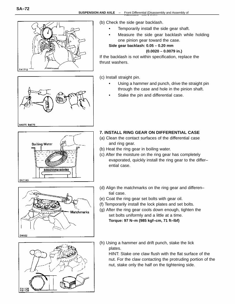
(b) Check the side gear backlash.
• Temporarily install the side gear shaft.
• Measure the side gear backlash while holdingone pinion gear toward the case.
Side gear backlash: 0.05 – 0.20 mm(0.0020 – 0.0079 in.)
If the backlash is not within specification, replace thethrust washers.
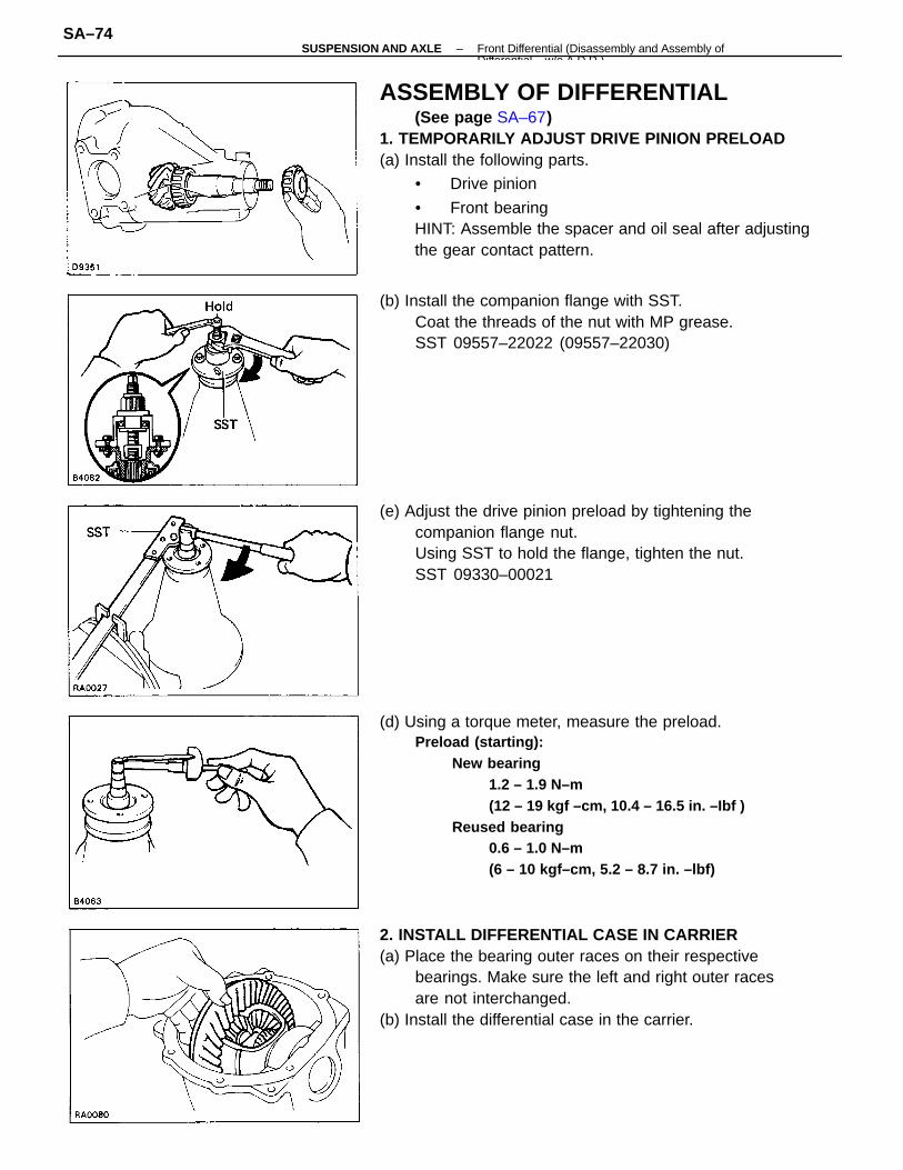
7. INSTALL RING GEAR ON DIFFERENTIAL CASE(a) Clean the contact surfaces of the differential case
and ring gear.(b) Heat the ring gear in boiling water.(c) After the moisture on the ring gear has completely
evaporated, quickly install the ring gear to the differ–ential case.
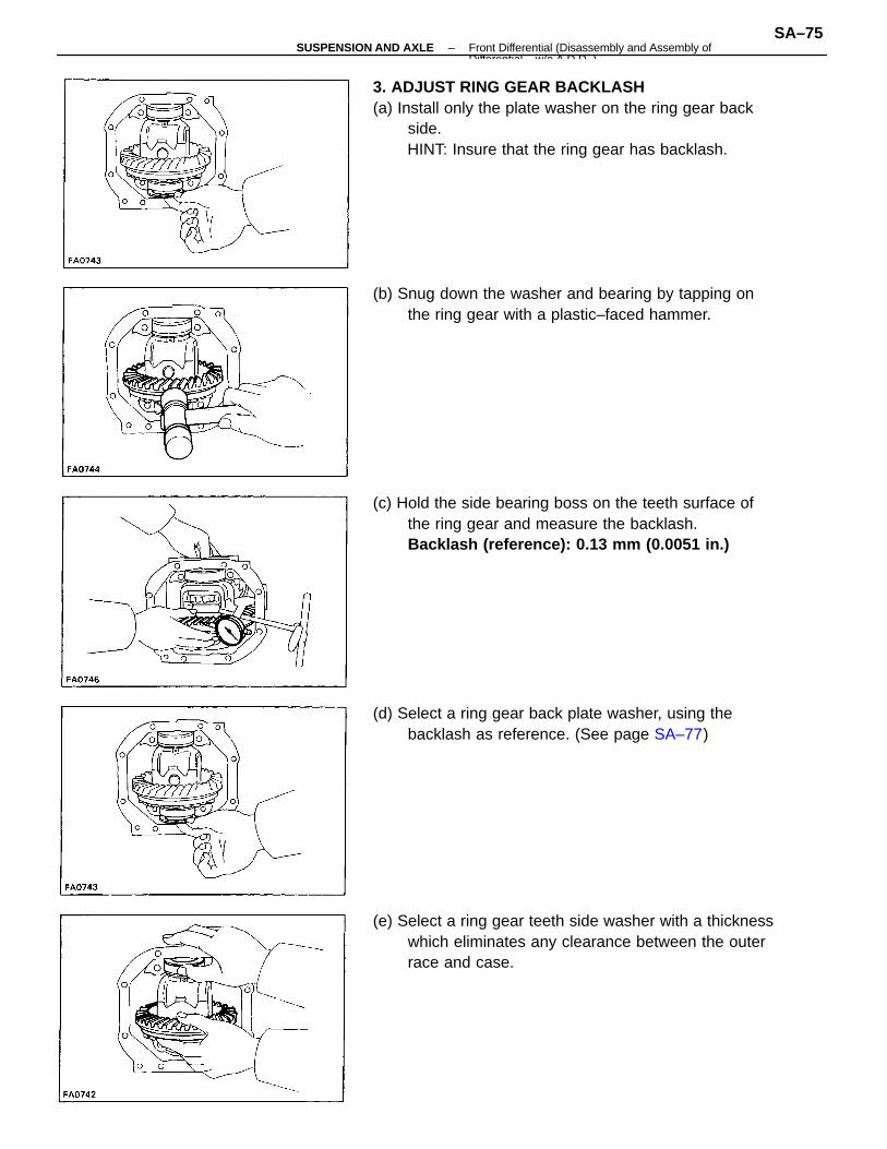
(d) Align the matchmarks on the ring gear and differen–tial case.
(e) Coat the ring gear set bolts with gear oil.(f) Temporarily install the lock plates and set bolts.(g) After the ring gear cools down enough, tighten the
set bolts uniformly and a little at a time.Torque: 97 N–m (985 kgf–cm, 71 ft–lbf)
(h) Using a hammer and drift punch, stake the lickplates.HINT: Stake one claw flush with the flat surface of thenut. For the claw contacting the protruding portion of thenut, stake only the half on the tightening side.
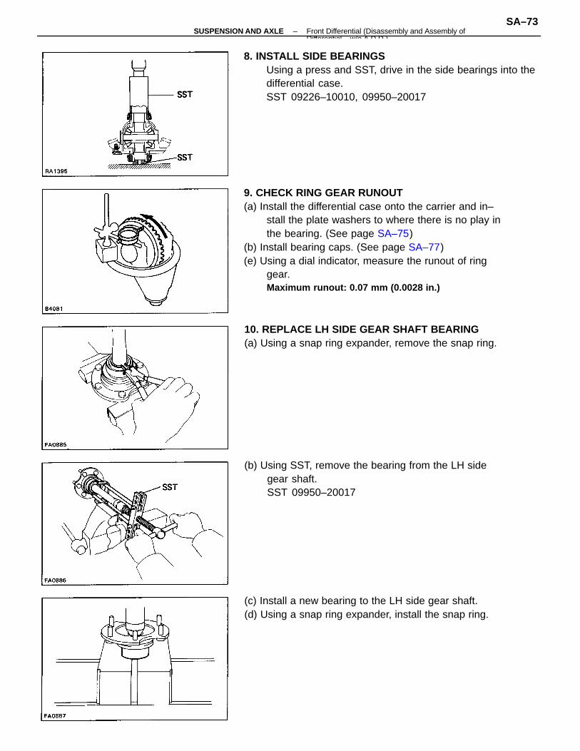
(c) Install straight pin.
• Using a hammer and punch, drive the straight pinthrough the case and hole in the pinion shaft.
• Stake the pin and differential case.
–SUSPENSION AND AXLE Front Differential (Disassembly and Assembly ofDifferential w/o A D D )
SA–72
9. CHECK RING GEAR RUNOUT(a) Install the differential case onto the carrier and in–
stall the plate washers to where there is no play inthe bearing. (See page SA–75)
(b) Install bearing caps. (See page SA–77)(e) Using a dial indicator, measure the runout of ring
gear.Maximum runout: 0.07 mm (0.0028 in.)
8. INSTALL SIDE BEARINGSUsing a press and SST, drive in the side bearings into thedifferential case.SST 09226–10010, 09950–20017
(b) Using SST, remove the bearing from the LH sidegear shaft.SST 09950–20017
10. REPLACE LH SIDE GEAR SHAFT BEARING(a) Using a snap ring expander, remove the snap ring.
(c) Install a new bearing to the LH side gear shaft.(d) Using a snap ring expander, install the snap ring.
–SUSPENSION AND AXLE Front Differential (Disassembly and Assembly ofDifferential w/o A D D )
SA–73
ASSEMBLY OF DIFFERENTIAL(See page SA–67)
1. TEMPORARILY ADJUST DRIVE PINION PRELOAD(a) Install the following parts.
• Drive pinion
• Front bearingHINT: Assemble the spacer and oil seal after adjustingthe gear contact pattern.
(d) Using a torque meter, measure the preload.Preload (starting):
New bearing1.2 – 1.9 N–m(12 – 19 kgf –cm, 10.4 – 16.5 in. –Ibf )
Reused bearing0.6 – 1.0 N–m(6 – 10 kgf–cm, 5.2 – 8.7 in. –lbf)
2. INSTALL DIFFERENTIAL CASE IN CARRIER(a) Place the bearing outer races on their respective
bearings. Make sure the left and right outer racesare not interchanged.
(b) Install the differential case in the carrier.
(e) Adjust the drive pinion preload by tightening thecompanion flange nut.Using SST to hold the flange, tighten the nut.SST 09330–00021
(b) Install the companion flange with SST.Coat the threads of the nut with MP grease.SST 09557–22022 (09557–22030)
–SUSPENSION AND AXLE Front Differential (Disassembly and Assembly ofDifferential w/o A D D )
SA–74
3. ADJUST RING GEAR BACKLASH(a) Install only the plate washer on the ring gear back
side.HINT: Insure that the ring gear has backlash.
(c) Hold the side bearing boss on the teeth surface ofthe ring gear and measure the backlash.Backlash (reference): 0.13 mm (0.0051 in.)
(e) Select a ring gear teeth side washer with a thicknesswhich eliminates any clearance between the outerrace and case.
(d) Select a ring gear back plate washer, using thebacklash as reference. (See page SA–77)
(b) Snug down the washer and bearing by tapping onthe ring gear with a plastic–faced hammer.
–SUSPENSION AND AXLE Front Differential (Disassembly and Assembly ofDifferential w/o A D D )
SA–75
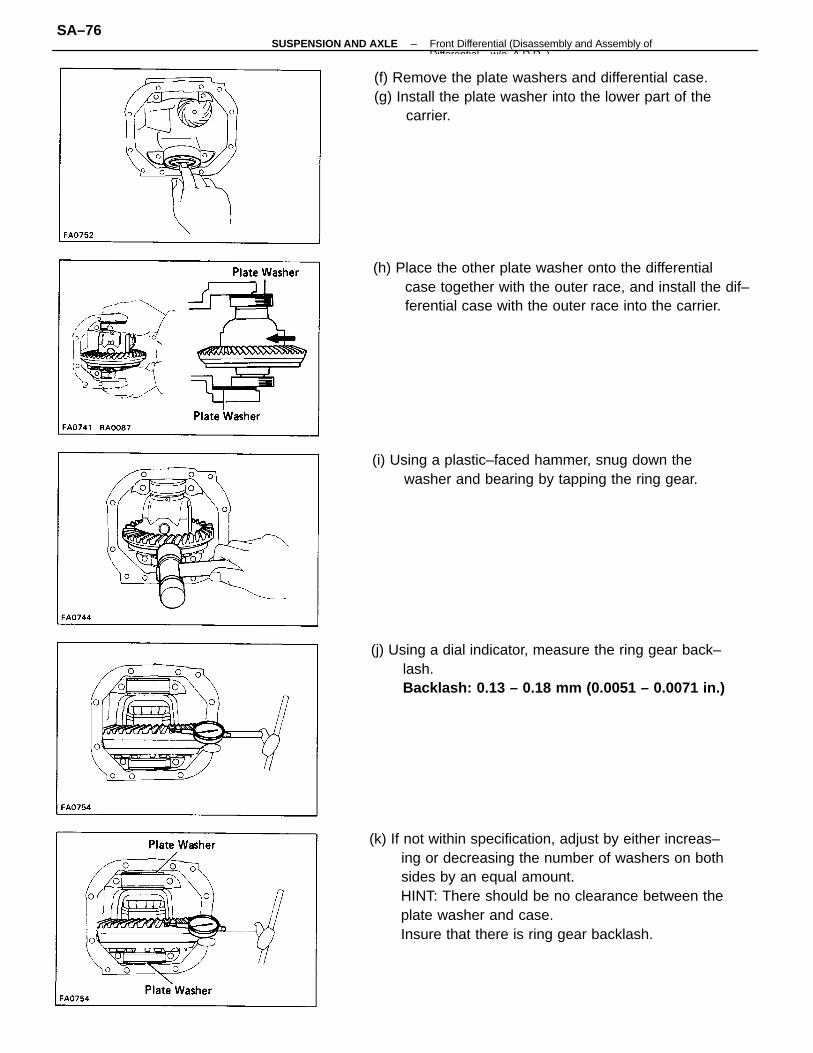
(k) If not within specification, adjust by either increas–ing or decreasing the number of washers on bothsides by an equal amount.HINT: There should be no clearance between theplate washer and case.Insure that there is ring gear backlash.
(j) Using a dial indicator, measure the ring gear back–lash.Backlash: 0.13 – 0.18 mm (0.0051 – 0.0071 in.)
(f) Remove the plate washers and differential case.(g) Install the plate washer into the lower part of the
carrier.
(h) Place the other plate washer onto the differentialcase together with the outer race, and install the dif–ferential case with the outer race into the carrier.
(i) Using a plastic–faced hammer, snug down thewasher and bearing by tapping the ring gear.
–SUSPENSION AND AXLE Front Differential (Disassembly and Assembly ofDifferential w/o A D D )
SA–76
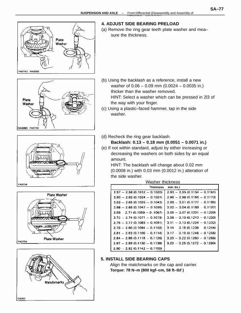
(d) Recheck the ring gear backlash.Backlash: 0.13 – 0.18 mm (0.0051 – 0.0071 in.)
(e) If not within standard, adjust by either increasing ordecreasing the washers on both sides by an equalamount.HINT: The backlash will change about 0.02 mm(0.0008 in.) with 0.03 mm (0.0012 in.) alteration ofthe side washer.
Washer thickness
(b) Using the backlash as a reference, install a newwasher of 0.06 – 0.09 mm (0.0024 – 0.0035 in.)thicker than the washer removed.HINT: Select a washer which can be pressed in 2l3 ofthe way with your finger.
(c) Using a plastic–faced hammer, tap in the sidewasher.
4. ADJUST SIDE BEARING PRELOAD(a) Remove the ring gear teeth plate washer and mea–
sure the thickness.
5. INSTALL SIDE BEARING CAPSAlign the matchmarks on the cap and carrier.Torque: 78 N–m (800 kgf–cm, 58 ft–Ibf )
–SUSPENSION AND AXLE Front Differential (Disassembly and Assembly ofDifferential w/o A D D )
SA–77
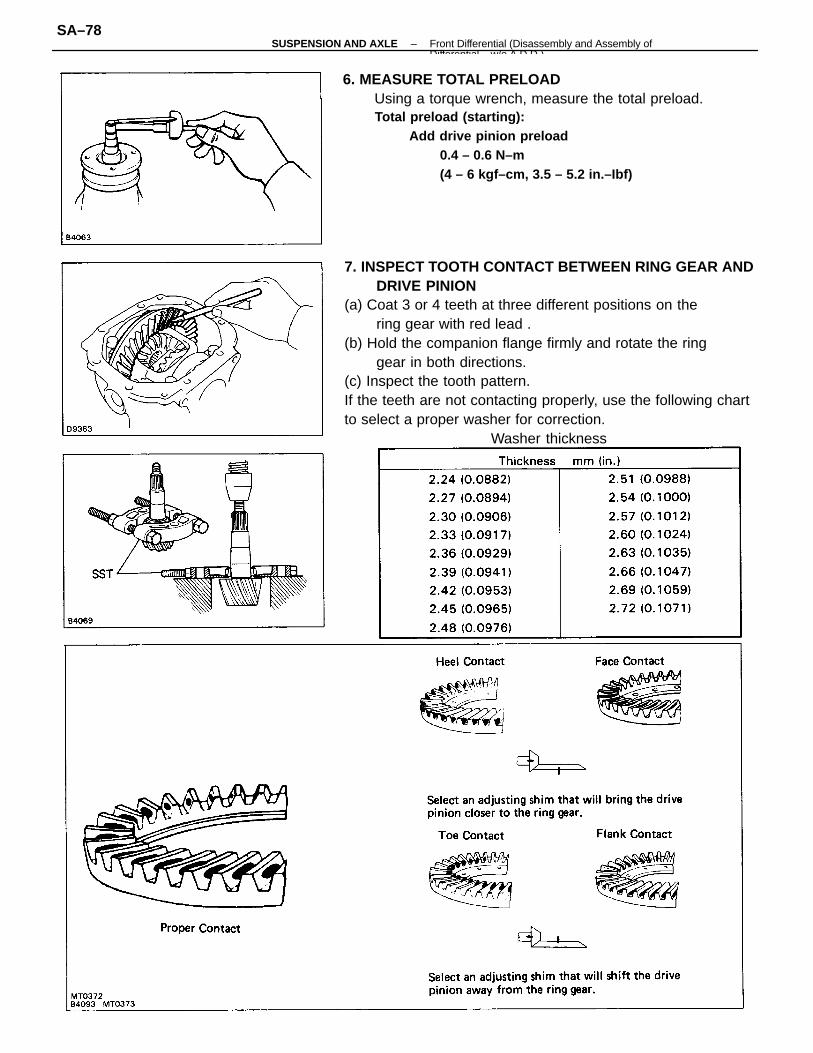
7. INSPECT TOOTH CONTACT BETWEEN RING GEAR ANDDRIVE PINION
(a) Coat 3 or 4 teeth at three different positions on thering gear with red lead .
(b) Hold the companion flange firmly and rotate the ringgear in both directions.
(c) Inspect the tooth pattern.If the teeth are not contacting properly, use the following chartto select a proper washer for correction.
Washer thickness
6. MEASURE TOTAL PRELOADUsing a torque wrench, measure the total preload.Total preload (starting):
Add drive pinion preload0.4 – 0.6 N–m(4 – 6 kgf–cm, 3.5 – 5.2 in.–Ibf)
–SUSPENSION AND AXLE Front Differential (Disassembly and Assembly ofDifferential w/o A D D )
SA–78
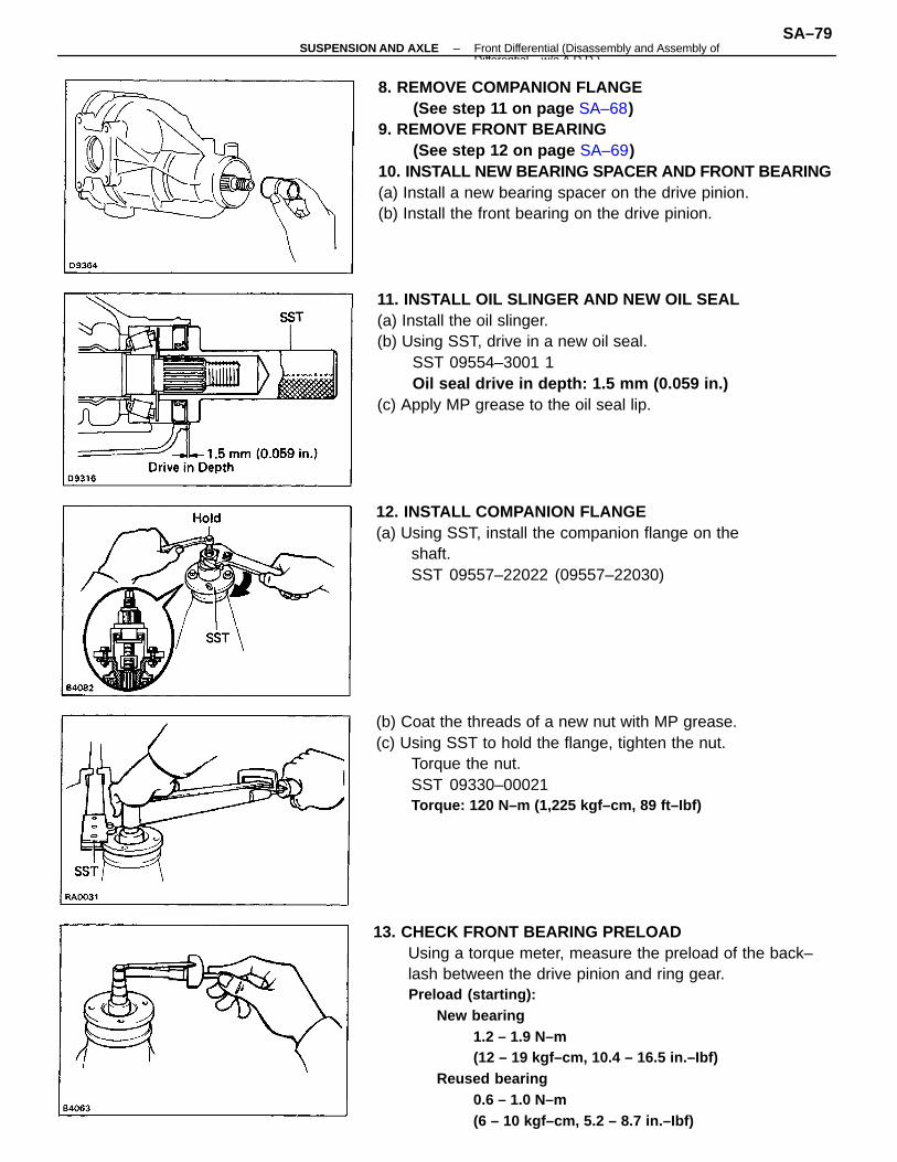
13. CHECK FRONT BEARING PRELOADUsing a torque meter, measure the preload of the back–lash between the drive pinion and ring gear.Preload (starting):
New bearing1.2 – 1.9 N–m(12 – 19 kgf–cm, 10.4 – 16.5 in.–Ibf)
Reused bearing0.6 – 1.0 N–m(6 – 10 kgf–cm, 5.2 – 8.7 in.–Ibf)
8. REMOVE COMPANION FLANGE(See step 11 on page SA–68)
9. REMOVE FRONT BEARING(See step 12 on page SA–69)
10. INSTALL NEW BEARING SPACER AND FRONT BEARING(a) Install a new bearing spacer on the drive pinion.(b) Install the front bearing on the drive pinion.
11. INSTALL OIL SLINGER AND NEW OIL SEAL(a) Install the oil slinger.(b) Using SST, drive in a new oil seal.
SST 09554–3001 1Oil seal drive in depth: 1.5 mm (0.059 in.)
(c) Apply MP grease to the oil seal lip.
(b) Coat the threads of a new nut with MP grease.(c) Using SST to hold the flange, tighten the nut.
Torque the nut.SST 09330–00021Torque: 120 N–m (1,225 kgf–cm, 89 ft–Ibf)
12. INSTALL COMPANION FLANGE(a) Using SST, install the companion flange on the
shaft.SST 09557–22022 (09557–22030)
–SUSPENSION AND AXLE Front Differential (Disassembly and Assembly ofDifferential w/o A D D )
SA–79
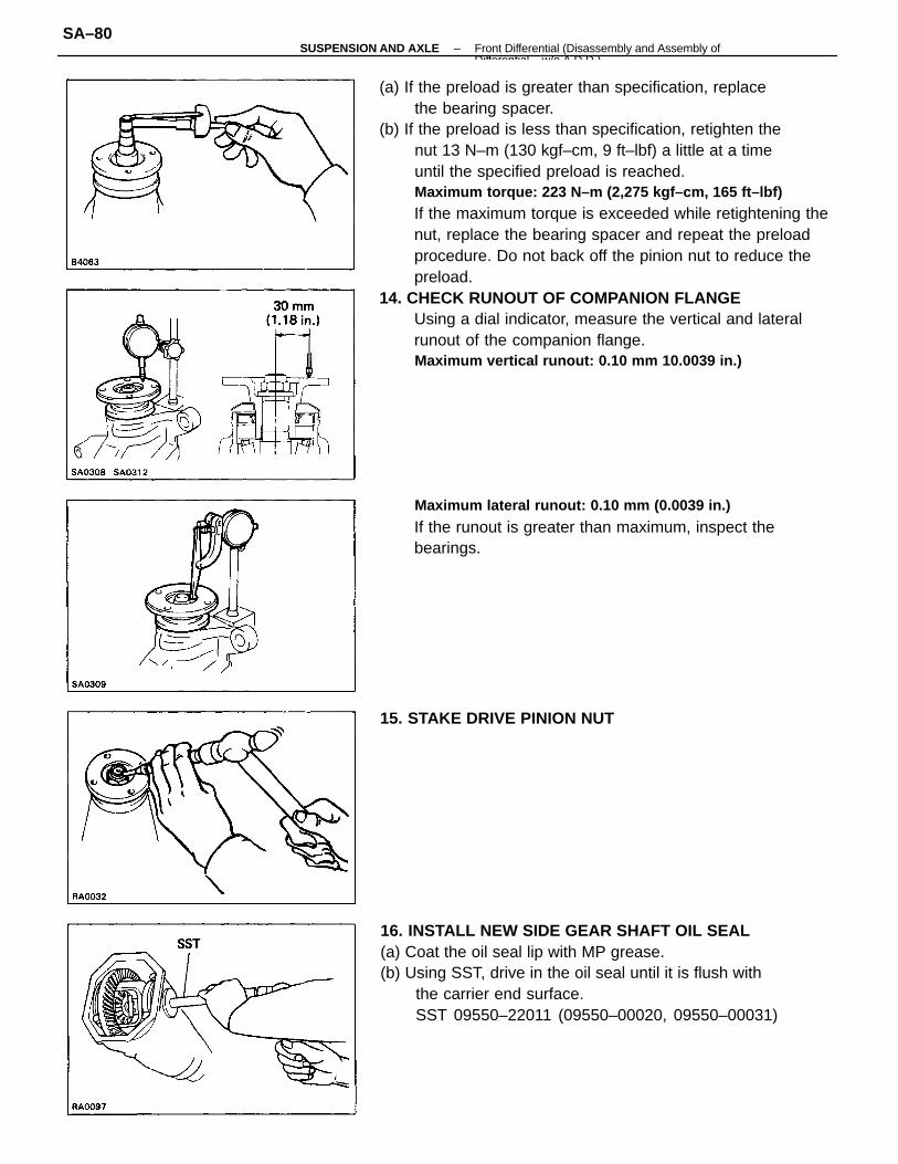
(a) If the preload is greater than specification, replacethe bearing spacer.
(b) If the preload is less than specification, retighten thenut 13 N–m (130 kgf–cm, 9 ft–lbf) a little at a timeuntil the specified preload is reached.Maximum torque: 223 N–m (2,275 kgf–cm, 165 ft–lbf)
If the maximum torque is exceeded while retightening thenut, replace the bearing spacer and repeat the preloadprocedure. Do not back off the pinion nut to reduce thepreload.
14. CHECK RUNOUT OF COMPANION FLANGEUsing a dial indicator, measure the vertical and lateralrunout of the companion flange.Maximum vertical runout: 0.10 mm 10.0039 in.)
16. INSTALL NEW SIDE GEAR SHAFT OIL SEAL(a) Coat the oil seal lip with MP grease.(b) Using SST, drive in the oil seal until it is flush with
the carrier end surface.SST 09550–22011 (09550–00020, 09550–00031)
Maximum lateral runout: 0.10 mm (0.0039 in.)
If the runout is greater than maximum, inspect thebearings.
15. STAKE DRIVE PINION NUT
–SUSPENSION AND AXLE Front Differential (Disassembly and Assembly ofDifferential w/o A D D )
SA–80
19. INSTALL DIFFERENTIAL CARRIER COVER(a) Remove any packing material and be careful not to
drop oil on the contacting surface of the differentialcarrier or carrier cover.
(b) Apply seal packing to the carrier cover.Seal packing: Part No. 08826–00090, THREE BOND
1281 or equivalent
HINT: Install the carrier cover within ten minutes afterapplying seal packing.
18. INSTALL SIDE GEAR SHAFTS(a) Before installing the shafts, replace the snap ring.(b) Using SST, install the side gear shafts to the differ–
ential carrier.SST 09910–00015(09911–00011, 09912–00010, 09914–00011)
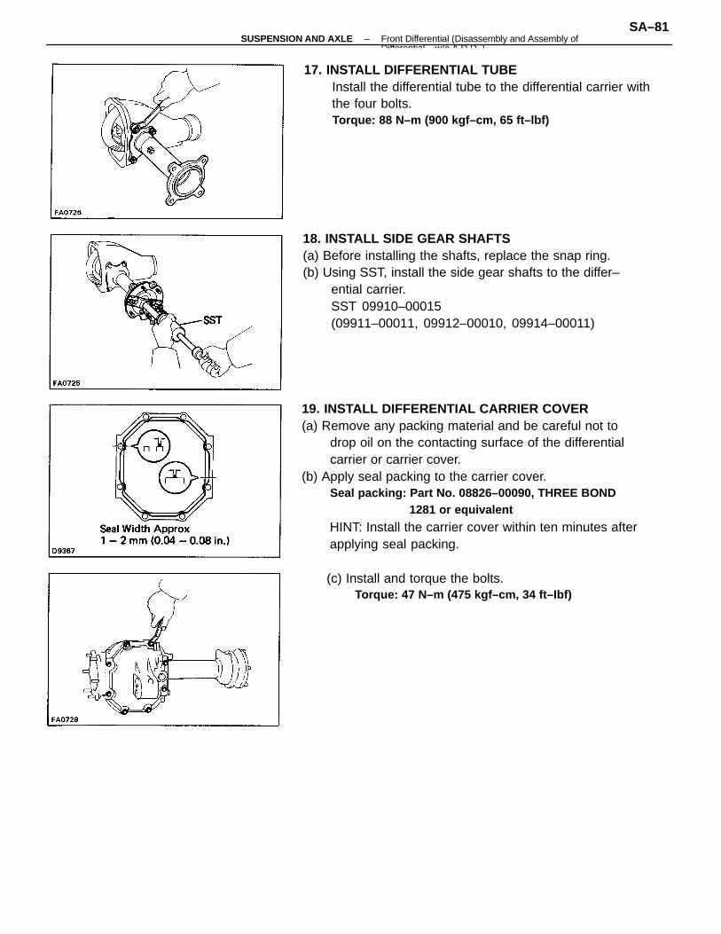
17. INSTALL DIFFERENTIAL TUBEInstall the differential tube to the differential carrier withthe four bolts.Torque: 88 N–m (900 kgf–cm, 65 ft–lbf)
(c) Install and torque the bolts.Torque: 47 N–m (475 kgf–cm, 34 ft–Ibf)
–SUSPENSION AND AXLE Front Differential (Disassembly and Assembly ofDifferential w/o A D D )
SA–81