Embed Size (px)
Citation preview
8/6/2019 A4K Technical Manual_(080528)
http://slidepdf.com/reader/full/a4k-technical-manual080528 1/32 - 1 -
TTAABBLLEE OOFF CCOONNTTEENNTTSS
1.... INDEX ...................... ......... 1
2.... INSTRUCTION............................... 3
3.... SAFETY INSTRUCTION............................... 4
4.... INTRODUCTION .................................. 5~14
4.1 SYSTEM TYPES. . . . . . . . . . . . . . . . . . . . . . . . . . . . . . . . . . . 5~6
4.1.1 8-PUSHBUTTON TYPES. . . . . . . . . . . . . . . . . . . . . . . . . . . . . . . . . .
5
4.1.2 12-PUSHBUTTON TYPES. . . . . . . . . . . . . . . . . . . . . . . . . . . . . . . . . . .
6
4.2 TRANSMITTER INSTRUCTION. . . . . . . . . . . . . . . . . . . . . . . . . . . . . . . . . . 7~11
4.2.1 TRANSMITTER OUTLINE. . . . . . . . . . . . . . . . . . . . . . . . . . . . . . . . . . .
7
4.2.2 TRANSMITTER EXTERNAL OUTLINE. . . . . . . . . . . . . . . . . . . . . . . . . . . . . . . . .
7
4.2.3 TRANSMITTER EXPLOSION VIEW. . . . . . . . . . . . . . . . . . . . . . . . . . . . . . . . .
84.2.4 TRANSMITTER INTERIOR DESCRIPTIONS
. . . . . . . . . . . . . . . . . . . . . . . . . . . . . . . . . .
9~10
4.2.5 HOW TO CHANGE SELECT SWITCH/ PUSHBUTTON. . . . . . . . . . . . . . . . . . . . . . . . . .
10
4.2.6 (1) RECHARGEABLE BATTERY (2) BATTERY CHARGER (3) SHOULDER STRAP. . . .
10
4.2.7 RECHARGEABLE BATTERY OUTPUT CONTACT DIAGRAM. . . . . . . . . . . . . . . . . . . . . . .
10
4.2.8 BATTERY CHARGER EXTERNAL DESCRIPTIONS. . . . . . . . . . . . . . . . . . . . . . . . . . . . . . . . .
11
4.3 RECEIVER INSTRUCTION. . . . . . . . . . . . . . . . . . . . . . . . . . . . . . . . . 12~14
4.3.1 RECEIVER OUTLINE. . . . . . . . . . . . . . . . . . . . . . . . . . . . . . . . .
12
4.3.2 RECEIVER EXTERNAL DESCRIPTION. . . . . . . . . . . . . . . . . . . . . . . . . . . . . . . .
12
4.3.3 RECEIVER EXPLOSION VIEW. . . . . . . . . . . . . . . . . . . . . . . . . . . . . . . . .
12
4.3.4 (1) RX MODULE CARD (2) DECODER CARD (3) RELAY CARD (4) POWER SUPPLY CARD 13~14
5.... SYSTEM CONFIGURATIONS................................. 15~22
5.1 SECURITY ID CODE SETTINGS. . . . . . . . . . . . . . . . . . . . . . . . . . . . . . . . . .
15
5.2 FREQUENCY (RF) CHANNEL SETTINGS. . . . . . . . . . . . . . . . . . . . . . . . . . . . . . . . 15
5.3 TRANSMITTER/ RECEIVER FUNCTION SETTING (REFER SOFTWARE MANUAL).
16
5.4 JUMPER SETTING – J1, J2. . . . . . . . . . . . . . . . . . . . . . . . . . . . . . . . . . . . . . . . . . . .
.
16
5.5 HOW TO CHANGE PUSHBUTTON (IMPORTANT). . . . . . . . . . . . . . . . . . . . . . . . .
165.6 OPTIONAL FEATURE: INFRARED STARTUP
. . . . . . . . . . . . . . . . . . . . . . . . . . . . . . .
17
5.6.1 INFRARED STARTUP ACCRESSORIES. . . . . . . . . . . . . . . . . . . . . . . . . . . . . . . . . . . . . . . . .
17
5.6.2 SET “INFRARED STARTUP” TO CHIP CARDS. . . . . . . . . . . . . . . . . . . . . . . . . . . . . . . . . . . . . . . 17
5.7 TANDEM (DUAL MASTER) MODE. . . . . . . . . . . . . . . . . . . . . . . . . . . . . . . . . . . 18
5.8 PITCH AND CATCH MODE. . . . . . . . . . . . . . . . . . . . . . . . . . . . . . . . . . .
18
5.9 1R2T PROTECTION. . . . . . . . . . . . . . . . . . . . . . . . . . . . . . . . . . . 18
5.10 TRANSMITTER CHANNEL IS SELECTABLE. . . . . . . . . . . . . . . . . . . . . 19~20
5.11 FREQUENCY (RF) CHANNEL TABLE: 433MHz. . . . . . . . . . . . . . . . . . . .
215.12 FREQUENCY (RF) CHANNEL TABLE: 173/301/350/418/447/480MHz . . . . . . . . . 22
8/6/2019 A4K Technical Manual_(080528)
http://slidepdf.com/reader/full/a4k-technical-manual080528 2/32 - 2 -
6.... TRANSMITTER OPERATION......................... 23~24
6.1 TRANSMITER OPERATION . . . . . . . . . . . . . . . . . . . . . . . . . . . . . . . . . . . . . . . . . . . . . . . . 23
6.2 TRANSMITTER LED DISPLAY & TROUBLE SHOOTING. . . . . . . . . . . . . . . . . . . . . . . . .
23~246.3 TRANSMITTER MAINTENANCE. . . . . . . . . . . . . . . . . . . . . . . . . . . . . . . . . . . . . . . . . . . . 24
7.... RECEIVER INSTALLATION .............................. 25`27
7.1 PREPARATION. . . . . . . . . . . . . . . . . . . . . . . . . . . . . . . . . .
25
7.2 STEP-BY-STEP INSTALLATION. . . . . . . . . . . . . . . . . . . . . . . . . . . . . . . . . . . .
26
7.3 RECEIVER LED DISPLAY & TROUBLE SHOOTING. . . . . . . . . . . . . . . . . . . . . . . . . . . .
27
8.... BATTERY CHARGING & BATTERY STATUS LED DISPLAY............ 28~29
8.1 BATTERY CHARGING . . . . . . . . . . . . . . . . . . . . . . . . . . . . . . . . . . . . . . . . . . . . . . . . . . . . 28
8.2 BATTERY STATUS LED DISPLAY & TROUBLE SHOOTING. . . . . . . . . . . . . . . . . . . . . . 29
9.... TROUBLE SHOOTING ............................. 30
10....SYSTEM SPECIFICATION................................... 31
10.1 TRANSMITTER SPECIFICATION. . . . . . . . . . . . . . . . . . . . . . . . . . . . . . . . . .
31
10.2 RECEVIER SPECIFICATION. . . . . . . . . . . . . . . . . . . . . . . . . . . . . . . . . . 31
10.3 BATTERY CHARGER SPECIFICATION. . . . . . . . . . . . . . . . . . . . . . . . . . . . . . . . . .
31
11....PARTS LIST .................................... 32
8/6/2019 A4K Technical Manual_(080528)
http://slidepdf.com/reader/full/a4k-technical-manual080528 3/32 - 3 -
2. INSTRUCTION
The Alpha 4000 series are highly durable, reliable and safe industrial radio remote control systems. The versatile
features of the Alpha 4000 series permit their use in many different remote control applications. The systems
can be used to control factory cranes, monorail systems, multiple hoists, trolleys, mining equipment, building
construction equipment, automatic control systems, and many others.
The system incorporates numerous safety circuits that guaranty maximum security and ensure the system is
resistant to outside interference. The major features of the Alpha 4000 series are as follow:
1. Alpha 4000 series has the automatic shut-off function, when encountering strong radio interference, and
when the transmitter/operator is out of receiving range. The receiver will start the automatic shutdown
function in 0.55 seconds.
2. The system is equipped with highly evolved software that has redundant error checking and correcting
capabilities to ensure 100% error-free transmission, decoding, and control of all output relays. This highly
evolved software includes CRC (Cyclical Redundancy Check) and Hamming Codes (Error Recovery)
programming.
3. The transmitter encoder and receiver decoder both utilize advanced microprocessor control. The availability
of 65,536 sets of unique ID codes will ensure that only commands from the matching control transmitter can
be carried out without any interference from other radio systems.
4. The system also utilizes advanced microprocessor control (watch dog) for data comparison and
crosschecking between the two decoding microprocessors. When fault are detected via this central
microprocessor, for maximum safety, the entire system will be shutdown immediately to avoid possibility of
any accidents occurring.
5. The Alpha 4000 series is equipped with numerous self-diagnosing functions:
MODE 1 (safe mode): If user in 40 seconds has not operated the transmitter, the transmitter will
automatic shutdown (multiple options by 40 second ~ 60 minutes, also may transmission
continuously and not close power source).
MODE 0 (power-saving model): Any has not operated the transmitter. The transmitter will automatic
shutdown for saving the power.
Alpha 4000 series includes one receiver, transmitter and battery charger. The major features as follows:
1. The transmitter casings are molded using industrial strength composite materials which are impervious to
dust, water, oil, acids, alkaline, heat and sunlight as well as being resistant to deformation due to long term
use in harsh environments. The pushbuttons are also constructed from industrial strength composite
materials with minimum of up to one million press cycles.2. Sensor-type battery charging. Metal and open type contact of battery charger provides water-proof and
strong construction of transmitter that fits every kind of environment. It also enables transmitter to charge
simply by putting it on battery charger.
3. The receiver manufactured by metal material to avoid strong radio interference and protect the internal
circuits.
4. Receiver internal circuits and modules are replaceable, such as RX modules card, decoder card, output relay
card and power supply card.
5. The system utilizes PLL synthesized RF transmission. It allows the user to select from 20 sets of frequency
channels best suited for the environment. The frequency channel is selected via simple dip-switch settings
inside the transmitter and receiver unit. 6. The transmitter and receiver both can be designed function at chip card.
7. Base on the system type selected, you may create all kinds of combination with the software to fit
different working environment.

8/6/2019 A4K Technical Manual_(080528)
http://slidepdf.com/reader/full/a4k-technical-manual080528 4/32 - 4 -
3. SAFETY INSTRUCTION
The following instructions should be strictly followed:
1. Make a daily check of the transmitter casing, pushbuttons and pushbutton rubber boot.Should it appear that anything could inhibit the proper operation of the transmitter unit, it
should be immediately removed from service.
2. Do not heat the battery or throw it into a fire. Do not touch the gold marking, for instance,
chip card, relay board, RX module and decoder board socket.
3. The transmitter voltage should be checked on a daily basis. If the voltage is low, the battery
pack should be recharged or replaced.
4. The emergency stop button (EMS) should be checked at the beginning of each shift to ensure
they are in the proper working order.
5. In the event of an emergency, push down the emergency stop button immediately to
deactivate the receiver main relay. Then turned the power “off” from the main power source
of the equipment.
6. The transmitter power key should be pulled “off” after each use and should never leave the
transmitter in the power “on” position when the unit is unattended.
7. Never operate a crane or equipment with two (2) transmitter units at the same time with
same frequency channel and ID code.
8. Do not use the same frequency channel and ID code as any other unit in use at the same
facility or within distance of 300 meters.
9. Ensure the waist belt and the shoulder strap is worn at all time during operation to avoid
accidental damages to the transmitter box.
10. When the transmitters and receivers should be repaired or adjustment. Refer all servicing to
qualified service personal. (Do not change parts like transistors, quartz… by yourselves.)
8/6/2019 A4K Technical Manual_(080528)
http://slidepdf.com/reader/full/a4k-technical-manual080528 5/32 - 5 -
4. INTRODUCTIONS
4.1 System Types
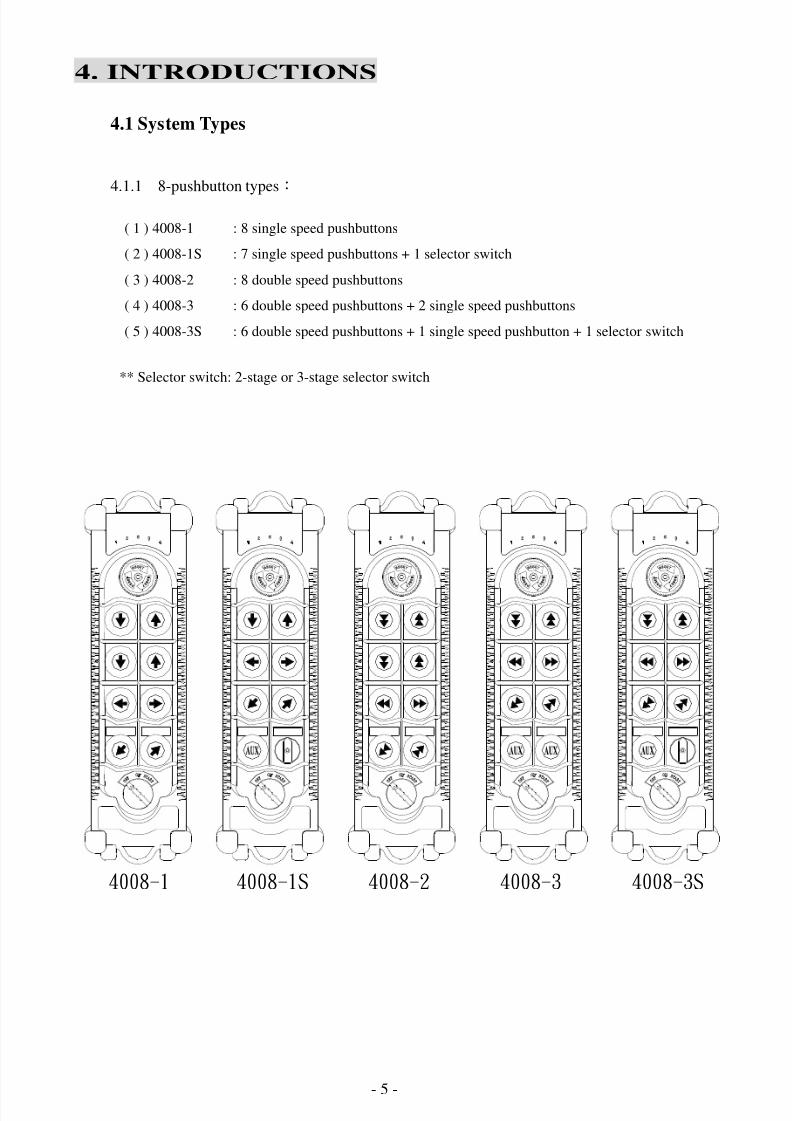
4.1.1 8-pushbutton types:
** Selector switch: 2-stage or 3-stage selector switch
( 1 ) 4008-1 : 8 single speed pushbuttons
( 2 ) 4008-1S : 7 single speed pushbuttons + 1 selector switch
( 3 ) 4008-2 : 8 double speed pushbuttons
( 4 ) 4008-3 : 6 double speed pushbuttons + 2 single speed pushbuttons
( 5 ) 4008-3S : 6 double speed pushbuttons + 1 single speed pushbutton + 1 selector switch
4008-3S4008-34008-24008-1S4008-1
8/6/2019 A4K Technical Manual_(080528)
http://slidepdf.com/reader/full/a4k-technical-manual080528 6/32 - 6 -
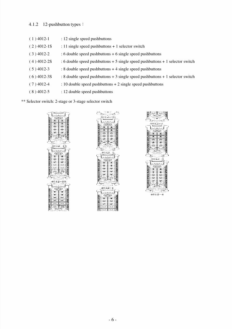
4.1.2 12-pushbutton types:
** Selector switch: 2-stage or 3-stage selector switch
4 0 1 2 - 1 4 0 1 2 - 1 S 4 0 1 2 - 2 4 0 1 2 - 3 4 0 1 2 - 4 4 0 1 2 - 3 S 4 0 1 2 - 2 S 4 0 1 2 - 5
( 1 ) 4012-1 : 12 single speed pushbuttons
( 2 ) 4012-1S : 11 single speed pushbuttons + 1 selector switch
( 3 ) 4012-2 : 6 double speed pushbuttons + 6 single speed pushbuttons
( 4 ) 4012-2S : 6 double speed pushbuttons + 5 single speed pushbuttons + 1 selector switch
( 5 ) 4012-3 : 8 double speed pushbuttons + 4 single speed pushbuttons
( 6 ) 4012-3S : 8 double speed pushbuttons + 3 single speed pushbuttons + 1 selector switch
( 7 ) 4012-4 : 10 double speed pushbuttons + 2 single speed pushbuttons
( 8 ) 4012-5 : 12 double speed pushbuttons
8/6/2019 A4K Technical Manual_(080528)
http://slidepdf.com/reader/full/a4k-technical-manual080528 7/32 - 7 -
4.2 Transmitter Instruction
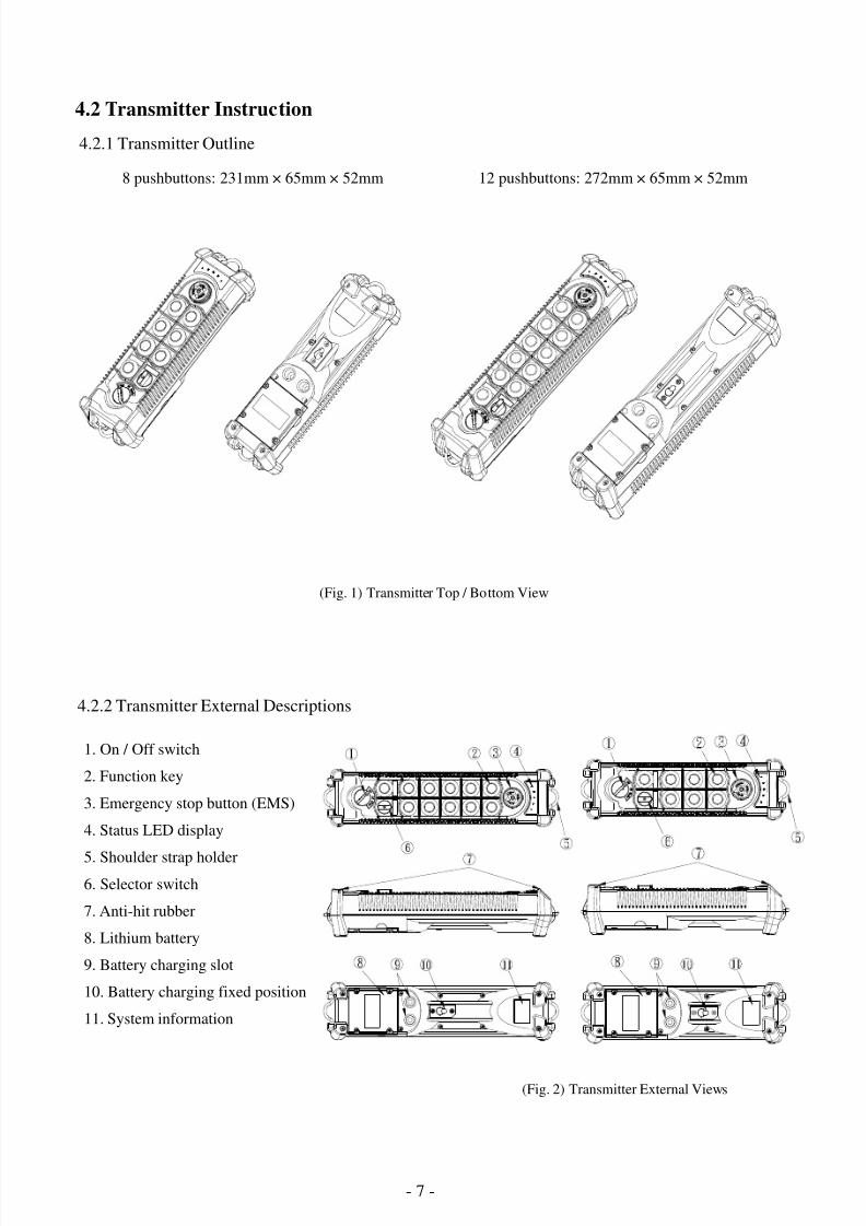
4.2.1 Transmitter Outline
8 pushbuttons: 231mm × 65mm × 52mm 12 pushbuttons: 272mm × 65mm × 52mm
(Fig. 1) Transmitter Top / Bottom View
4.2.2 Transmitter External Descriptions
1. On / Off switch
2. Function key
3. Emergency stop button (EMS)
4. Status LED display
5. Shoulder strap holder
6. Selector switch
7. Anti-hit rubber
8. Lithium battery
9. Battery charging slot
10. Battery charging fixed position
11. System information
(Fig. 2) Transmitter External Views
8
9
1 0
1
6
1 1
7
2
4
3
5
8
1 1
9
1 0
1
6
7
2
3
5
4
8/6/2019 A4K Technical Manual_(080528)
http://slidepdf.com/reader/full/a4k-technical-manual080528 8/32 - 8 -
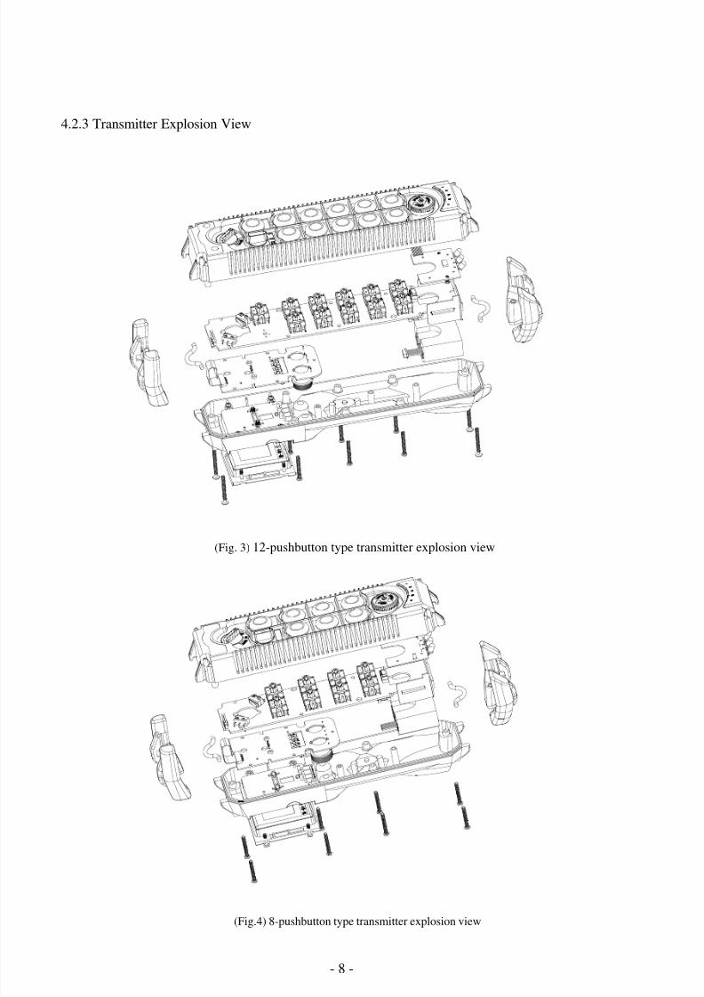
4.2.3 Transmitter Explosion View
(Fig. 3) 12-pushbutton type transmitter explosion view
(Fig.4) 8-pushbutton type transmitter explosion view
8/6/2019 A4K Technical Manual_(080528)
http://slidepdf.com/reader/full/a4k-technical-manual080528 9/32 - 9 -
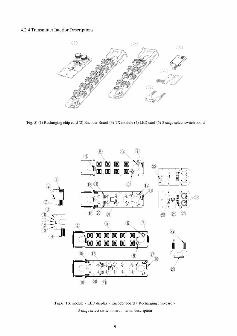
4.2.4 Transmitter Interior Descriptions
(Fig. 5) (1) Recharging chip card (2) Encoder Board (3) TX module (4) LED card (5) 3-stage select switch board
(Fig.6) TX module、
LED display、
Encoder board、
Recharging chip card、
3-stage select switch board internal description
1 0
1 3
1 2
1 1
1 4
2 0
1 9
2 1
S
H
1
1 5
1 6
4
5
3
9
2
1
1 6
1 9
1 5
2 1
2 0
S
H
1
4
5
2 3
1 8
8
6
7
1 7
2 8
2 7
1 7
8
1 8
6
7
2 2
2 4
2 5
2 6
8/6/2019 A4K Technical Manual_(080528)
http://slidepdf.com/reader/full/a4k-technical-manual080528 10/32 - 10 -
1. TX module RF channel dip-switch 2. TX quartz crystal frequency capacitor
3. TX module connector 4. Emergency Stop micro switch
5. One-speed, two-speed pushbuttons 6. Start micro switch
7. Induction power board to encoder board connector 8. Transmitter power micro switch
9. LED4 10. LED3
11. Status LED 12. LED2
13. LED1 14. LED connector
15. LED connector port 16. Function select dip-switch
17. Center CPU connector port 18. 3-stage Select switch board to encoder board connector
19. TX module connector port 20. ID code dip-switch
21. SH1 22. Encoder board to induction power board connector
23. J1, J2 jumper 24. Chip card holder
25. Battery terminal 26. Induction circuit
27. Select switch board to select board wire 28. Encoder board to 3-stage select switch board connector
4.2.5 How to Change Select Switch/ Pushbutton
1. Refer to 4.1 for transmitter types. And remove transmitter and receiver chip cards. (Note: When
change pushbutton to select switch type, you should insert 3-stage select switchboard, refer to Fig. 5).
2. Then solder SH1 short circuit for canceling original setting (Refer to Fig.6 for SH1 position).
3. Reset transmitter and receiver chip cards by programming tool. Then re-insert to transmitter and
receiver.
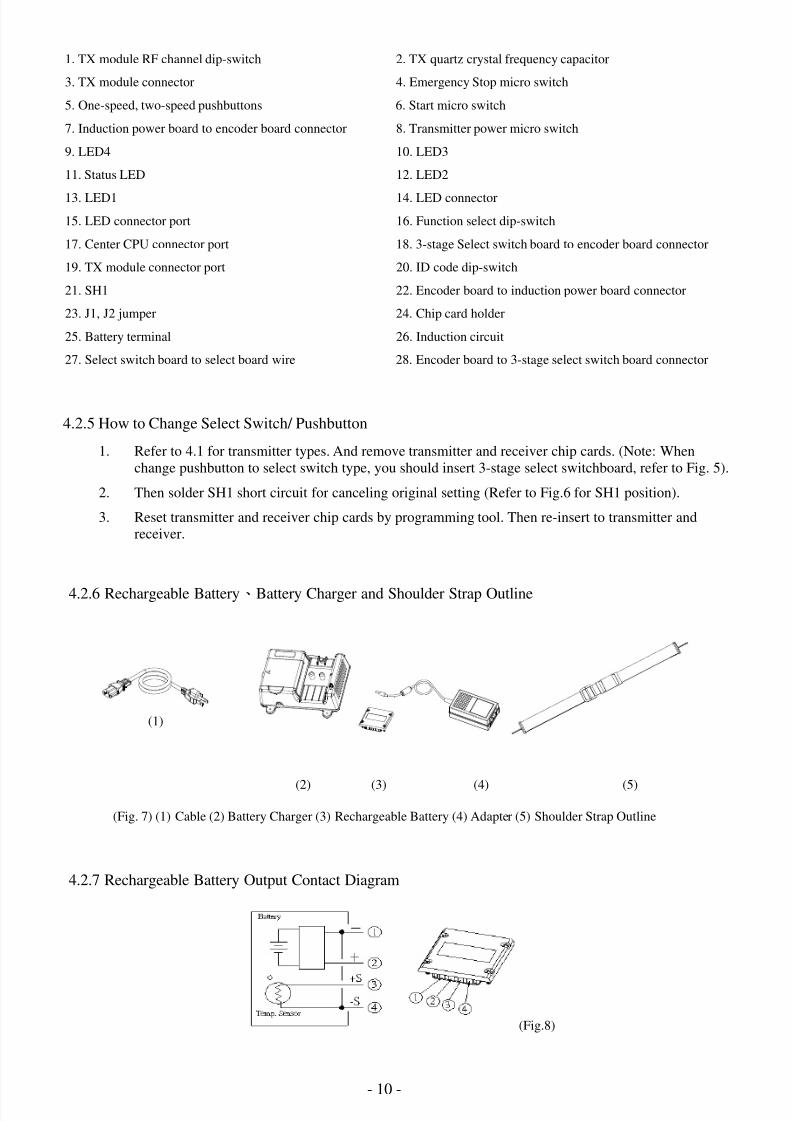
4.2.6 Rechargeable Battery、Battery Charger and Shoulder Strap Outline
(1)
(2) (3) (4) (5)
(Fig. 7) (1) Cable (2) Battery Charger (3) Rechargeable Battery (4) Adapter (5) Shoulder Strap Outline
4.2.7 Rechargeable Battery Output Contact Diagram
(Fig.8)
8/6/2019 A4K Technical Manual_(080528)
http://slidepdf.com/reader/full/a4k-technical-manual080528 11/32 - 11 -
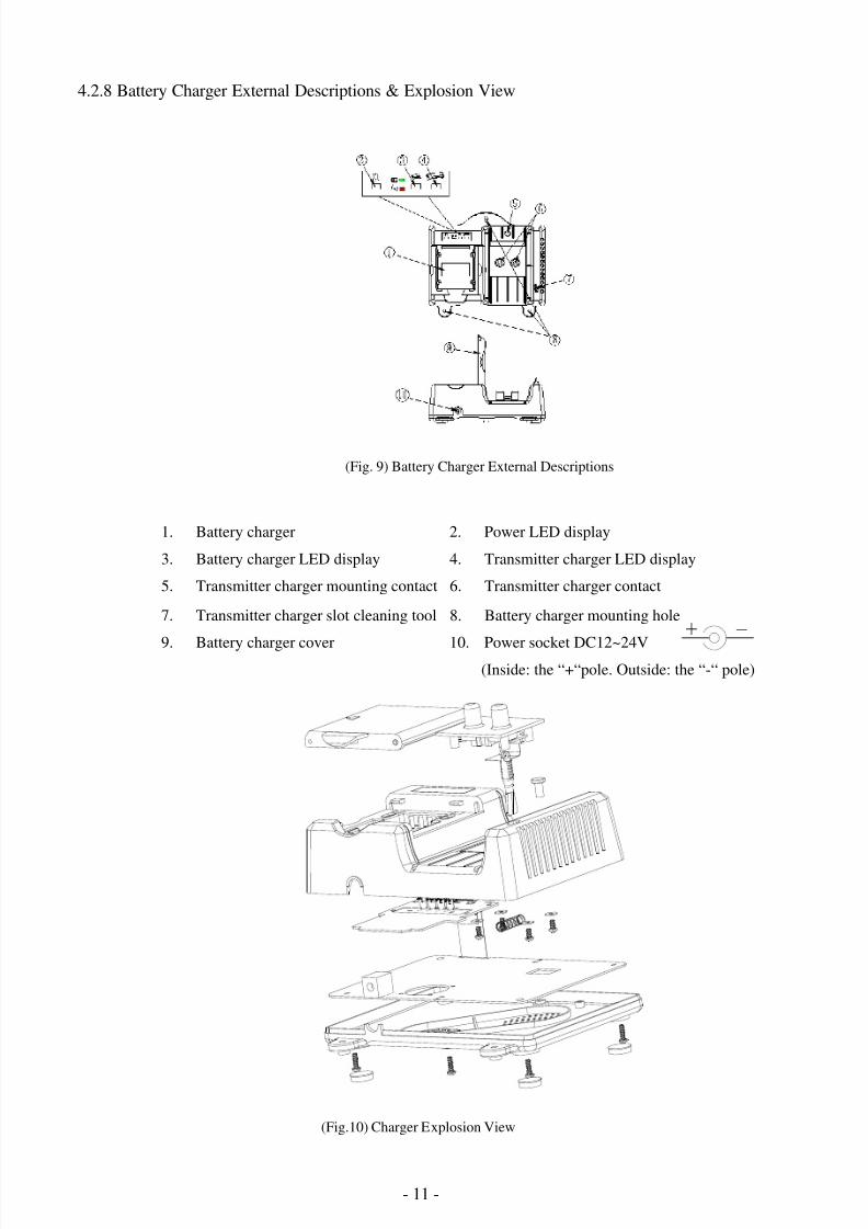
4.2.8 Battery Charger External Descriptions & Explosion View
(Fig. 9) Battery Charger External Descriptions
1. Battery charger 2. Power LED display
3. Battery charger LED display 4. Transmitter charger LED display
5. Transmitter charger mounting contact 6. Transmitter charger contact
7. Transmitter charger slot cleaning tool 8. Battery charger mounting hole
9. Battery charger cover 10. Power socket DC12~24V(Inside: the “+“pole. Outside: the “-“ pole)
(Fig.10) Charger Explosion View
_+
8/6/2019 A4K Technical Manual_(080528)
http://slidepdf.com/reader/full/a4k-technical-manual080528 12/32 - 12 -
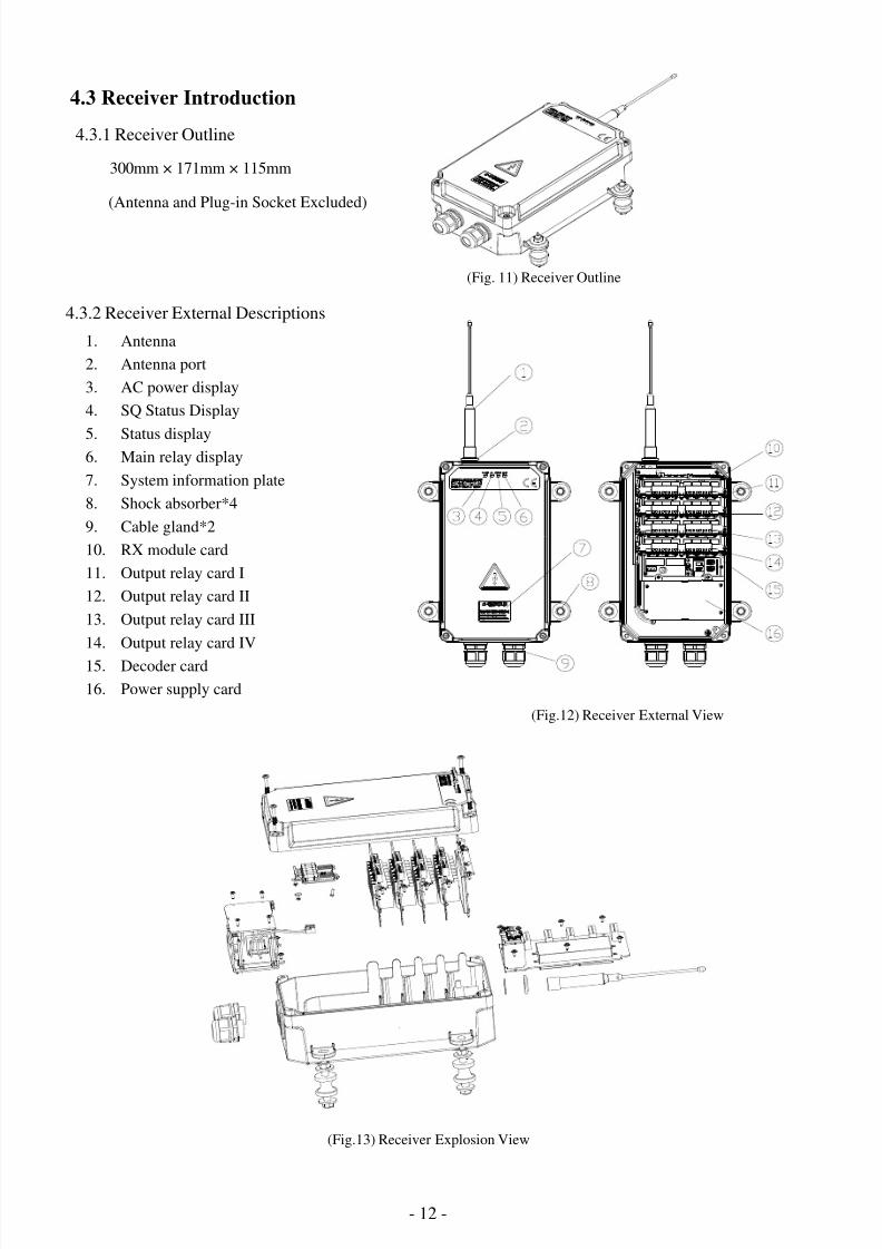
4.3 Receiver Introduction
4.3.1 Receiver Outline
300mm × 171mm × 115mm
(Antenna and Plug-in Socket Excluded)
(Fig. 11) Receiver Outline
4.3.2 Receiver External Descriptions
1. Antenna
2. Antenna port
3. AC power display
4. SQ Status Display
5. Status display6. Main relay display
7. System information plate
8. Shock absorber*4
9. Cable gland*2
10. RX module card
11. Output relay card I
12. Output relay card II
13. Output relay card III
14. Output relay card IV
15. Decoder card
16. Power supply card
(Fig.12) Receiver External View
(Fig.13) Receiver Explosion View
8/6/2019 A4K Technical Manual_(080528)
http://slidepdf.com/reader/full/a4k-technical-manual080528 13/32 - 13 -
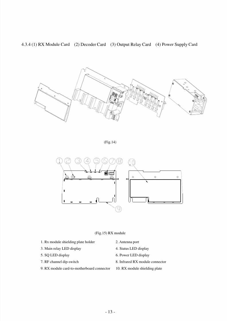
4.3.4 (1) RX Module Card (2) Decoder Card (3) Output Relay Card (4) Power Supply Card
(Fig.14)
(Fig.15) RX module
1. Rx module shielding plate holder 2. Antenna port
3. Main relay LED display 4. Status LED display
5. SQ LED display 6. Power LED display
7. RF channel dip-switch 8. Infrared RX module connector
9. RX module card-to-motherboard connector 10. RX module shielding plate

8/6/2019 A4K Technical Manual_(080528)
http://slidepdf.com/reader/full/a4k-technical-manual080528 14/32 - 14 -
(2) Decoder Board
1. Decoder shielding plate
2. Function select dip-switch
3. ID code dip-switch
4. Chip card holder
5. Chip card J1 & J2 socket
6. Power DC12V input connector
7. Spare power DC12V output connector
8. Main contact relay fuse 5A/250V
9. Main relay connector
10.Relay board contactor port IV
11. Relay board contactor port III
12. Relay board contactor port II
13. Relay board contactor port I
14. RX module connector port (圖 十 六
)解 碼 板
(Fig.16) Decoder Board
(3) Relay Board
1. Relay LED display
2. Relay output contact connector port
3. Contact relay holder
4. Contact relays
5. Relay LED display
6. Relay card-to-motherboard connector
(Fig.17) Relay Board
(4) Power Supply Card
1. Power supply board holder
2. Power DC12V2A output connector
3. Power input connector
4. Fuse slot
(Fig.18) Power supply module
8/6/2019 A4K Technical Manual_(080528)
http://slidepdf.com/reader/full/a4k-technical-manual080528 15/32 - 15 -
5. SYSTEM CONFIGURATIONS
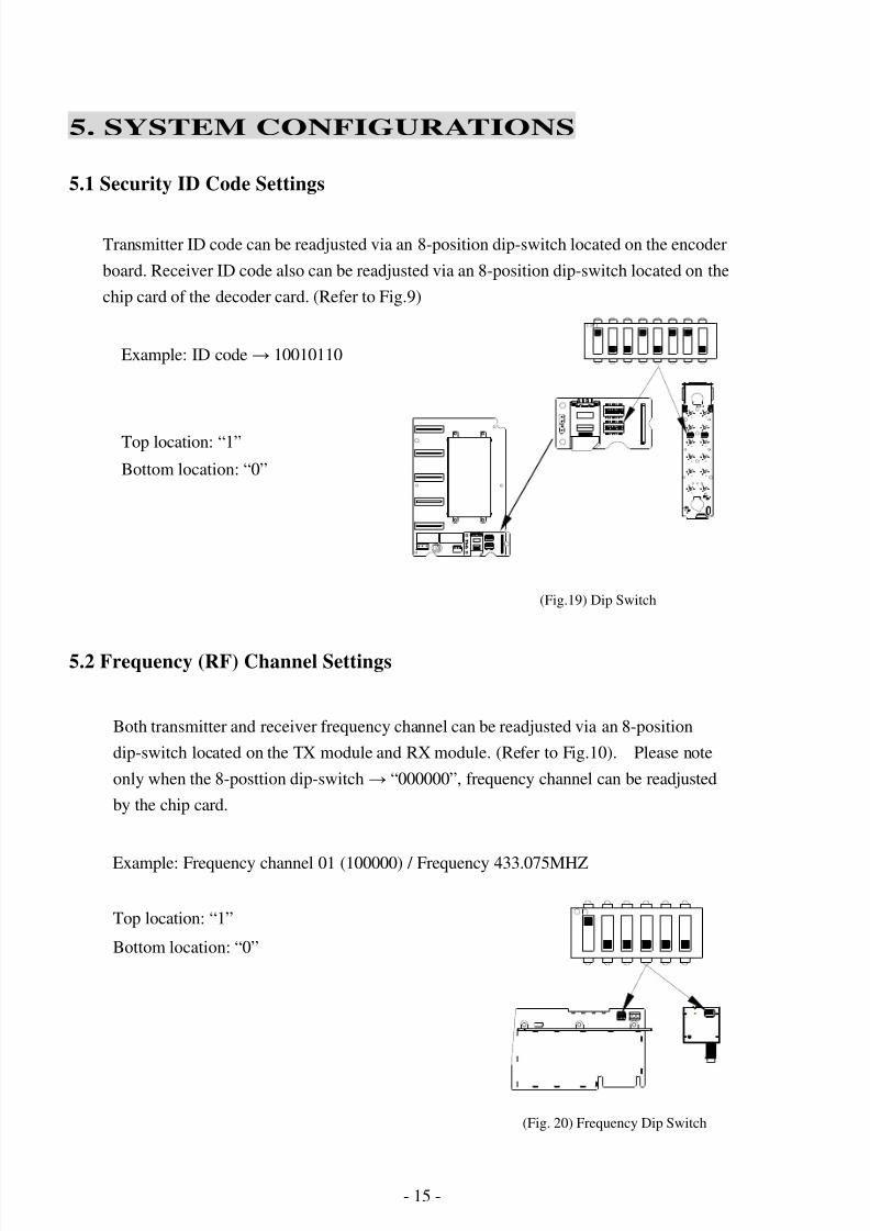
5.1 Security ID Code Settings
Transmitter ID code can be readjusted via an 8-position dip-switch located on the encoder
board. Receiver ID code also can be readjusted via an 8-position dip-switch located on the
chip card of the decoder card. (Refer to Fig.9)
Example: ID code→ 10010110
Top location: “1”
Bottom location: “0”
(Fig.19) Dip Switch
5.2 Frequency (RF) Channel Settings
Both transmitter and receiver frequency channel can be readjusted via an 8-position
dip-switch located on the TX module and RX module. (Refer to Fig.10). Please note
only when the 8-posttion dip-switch→ “000000”, frequency channel can be readjusted
by the chip card.
Example: Frequency channel 01 (100000) / Frequency 433.075MHZ
Top location: “1”
Bottom location: “0”
(Fig. 20) Frequency Dip Switch
8/6/2019 A4K Technical Manual_(080528)
http://slidepdf.com/reader/full/a4k-technical-manual080528 16/32 - 16 -
5.3 Transmitter / Receiver Function Setting (Please Refer Software Manual)
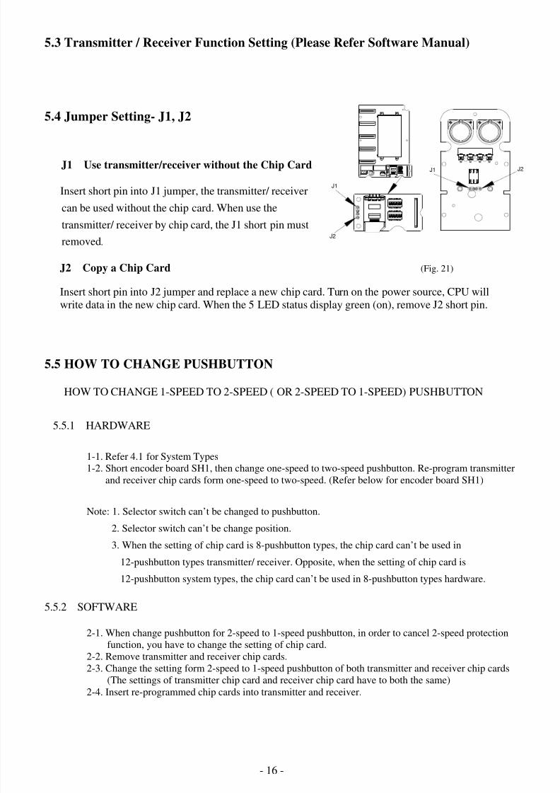
5.4 Jumper Setting- J1, J2
J1 Use transmitter/receiver without the Chip Card
Insert short pin into J1 jumper, the transmitter/ receiver
can be used without the chip card. When use the
transmitter/ receiver by chip card, the J1 short pin must
removed.
J2 Copy a Chip Card (Fig. 21)
Insert short pin into J2 jumper and replace a new chip card. Turn on the power source, CPU will
write data in the new chip card. When the 5 LED status display green (on), remove J2 short pin.
5.5 HOW TO CHANGE PUSHBUTTON
HOW TO CHANGE 1-SPEED TO 2-SPEED ( OR 2-SPEED TO 1-SPEED) PUSHBUTTON
5.5.1 HARDWARE
1-1. Refer 4.1 for System Types
1-2. Short encoder board SH1, then change one-speed to two-speed pushbutton. Re-program transmitter
and receiver chip cards form one-speed to two-speed. (Refer below for encoder board SH1)
Note: 1. Selector switch can’t be changed to pushbutton.
2. Selector switch can’t be change position.
3. When the setting of chip card is 8-pushbutton types, the chip card can’t be used in
12-pushbutton types transmitter/ receiver. Opposite, when the setting of chip card is
12-pushbutton system types, the chip card can’t be used in 8-pushbutton types hardware.
5.5.2 SOFTWARE
2-1. When change pushbutton for 2-speed to 1-speed pushbutton, in order to cancel 2-speed protection
function, you have to change the setting of chip card.
2-2. Remove transmitter and receiver chip cards.
2-3. Change the setting form 2-speed to 1-speed pushbutton of both transmitter and receiver chip cards
(The settings of transmitter chip card and receiver chip card have to both the same)
2-4. Insert re-programmed chip cards into transmitter and receiver.
J1
J2
J1 J2

8/6/2019 A4K Technical Manual_(080528)
http://slidepdf.com/reader/full/a4k-technical-manual080528 17/32 - 17 -
5.6 Optional Feature: Infrared Startup
(Fig. 22)
5.6.1 Infrared Startup Accessories:
1-1. Transmitter infrared LED sensor (refer to Fig.22)
1-2. Infrared receiving module (refer to Fig.22): If the ID code of the transmitter unit is altered via8-pin dip-switch setting inside the transmitter (refer to Fig.6), you must then also change
the ID code in the receiver (refer to page 14).
1-3. Infrared receiving module input connector (refer to Fig.22):
(1) GND (2) DC+8V (3) Infrared receiving module
5.6.2 Set “Infrared Startup” to chip card (refer to chapter 5.7 of software function setting manual).
If the system is equipped with “Infrared Startup” function, the operator then can only activate
the receiver MAIN relay within 100-meter linear distance from the location of the receiver or
the receiving infrared module. Point the infrared LED sensor located on the front of thetransmitter towards the infrared receiving module.
★ How to cancel “ Infrared Start” function
Insert pin both into (1) GND and (3) Infrared receiving module or remove Infrared receiving module
input connector (refer to Fig.22). Or reset transmitter and receiver chip cards without “Infrared start”
function.
Infrared receiving module
Transmitter infrared LED sensor
(Infrared receiving module connector
8/6/2019 A4K Technical Manual_(080528)
http://slidepdf.com/reader/full/a4k-technical-manual080528 18/32 - 18 -
5.7 Tandem (Dual Master) Mode
This mode allows two operators controlling two crane systems independently or one operator
controlling two crane systems simultaneously. (Crane I, Crane II, Crane I+II)
To operate in Tandem mode, please keep rotating the power switch to START position and
depressing Tandem button to select I, II or I+II, you may refer the LED status. Then release E-stop
switch → rotate the power to START again to operate the equipment. Note that the Tandem
pushbutton can only be set on the 7th
single-speed pushbutton for Alpha 4008 and 11th
single-speed
pushbutton for Alpha 4012. The two transmitters operated in Tandem mode should have different
channels and identical ID. It is only available under Mode 1. Please refer to below for LED status of
Tandem mode operation.
5.8 Pitch and Catch Mode
This mode allows two operators controlling one crane system from opposite ends of a long or cross
travel.
To operate in Pitch and Catch Mode, please depress the Release pushbutton and then rotate the
power switch to START position and release. The power of the receiver will be off (main relay will
be deactivated). Then, either turn on Transmitter 1 or Transmitter 2, the transmitter which be turned
on (activate main relay of the receiver) first will control the Crane.
Note that the Release pushbutton can only be set on the 7th
single-speed pushbutton for Alpha 4008
and 11th
single-speed pushbutton for Alpha 4012. The two transmitters operated in Pitch and Catch
mode should have different channels and same identical ID. It is only available under Mode 1.
5.9 1R2T Protection
Two transmitters to one receiver. For safety purpose, only one transmitter can control the receiver at
a time.
How to switch Transmitter 1/ Transmitter 2 to control the receiver in 1R2T protection
function:When the transmitter that controls the receiver is low-battery / depress emergency stop
button / rotate the power switch to OFF position. The main relay of receiver will be deactivated.
Then, either turn on Transmitter 1 again or turn on Transmitter 2, the transmitter which be turned on
first will control the receiver.
Note that the two transmitters operated in 1R2T Protection shall have same channels and identical
ID.
Crane I
Crane II
Crane I+II
: LED position 1: Red Light (LED position 2: Green Light)
: LED position 2: Red Light (LED position 1: Green Light)
: LED position 1 & 2: Red Light
8/6/2019 A4K Technical Manual_(080528)
http://slidepdf.com/reader/full/a4k-technical-manual080528 19/32 - 19 -
5.10 Transmitter Channel is Selectable
Operate a 3-step automatic return momentary selector switch to select transmitter channel.
Transmitter Channel is selectable function can be set on the 7th
single speed pushbutton on
8-pushbutton system types, 11th
single speed pushbutton on 12-pushbutton and 12+2-pushbutton
system types.
★ Transmitter shall have a 3-step automatic return momentary selector switch.
Start “Transmitter Channel is Selectable” function and identify Start channel and End channel
on transmitter chip card. When transmitter is operated in this function, receiver will
AUTOSCAN new channel.
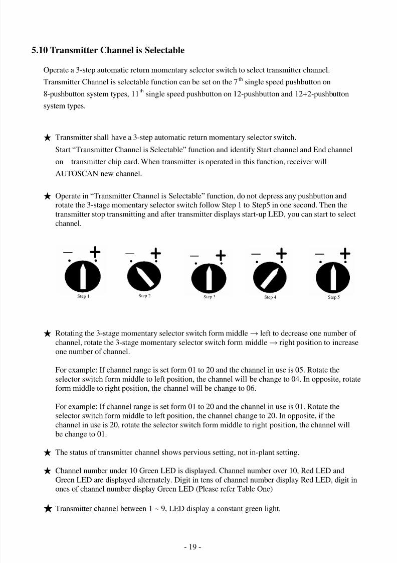
★ Operate in “Transmitter Channel is Selectable” function, do not depress any pushbutton androtate the 3-stage momentary selector switch follow Step 1 to Step5 in one second. Then the
transmitter stop transmitting and after transmitter displays start-up LED, you can start to select
channel.
★ Rotating the 3-stage momentary selector switch form middle→ left to decrease one number of
channel, rotate the 3-stage momentary selector switch form middle→ right position to increase
one number of channel.
For example: If channel range is set form 01 to 20 and the channel in use is 05. Rotate the
selector switch form middle to left position, the channel will be change to 04. In opposite, rotate
form middle to right position, the channel will be change to 06.
For example: If channel range is set form 01 to 20 and the channel in use is 01. Rotate the
selector switch form middle to left position, the channel change to 20. In opposite, if the
channel in use is 20, rotate the selector switch form middle to right position, the channel will
be change to 01.
★ The status of transmitter channel shows pervious setting, not in-plant setting.
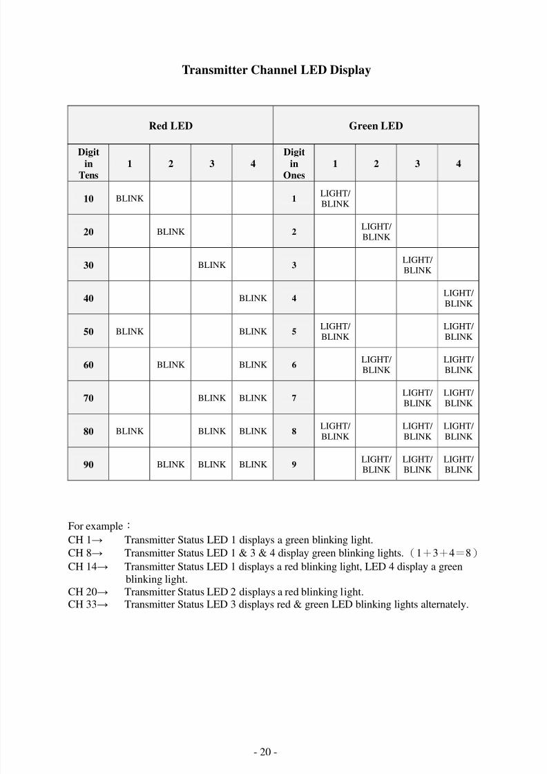
★ Channel number under 10 Green LED is displayed. Channel number over 10, Red LED and
Green LED are displayed alternately. Digit in tens of channel number display Red LED, digit inones of channel number display Green LED (Please refer Table One)
★ Transmitter channel between 1 ~ 9, LED display a constant green light.
- + . .
Step 1
- + . .
Step 3
- + . .
Step 4
- + . .
Step 5
- + . .
Step 2
8/6/2019 A4K Technical Manual_(080528)
http://slidepdf.com/reader/full/a4k-technical-manual080528 20/32 - 20 -
Transmitter Channel LED Display
Red LED Green LED
Digit
in
Tens
1 2 3 4
Digit
in
Ones
1 2 3 4
10 BLINK 1LIGHT/
BLINK
20 BLINK 2LIGHT/
BLINK
30 BLINK 3LIGHT/
BLINK
40 BLINK 4LIGHT/
BLINK
50 BLINK BLINK 5LIGHT/
BLINK
LIGHT/
BLINK
60 BLINK BLINK 6LIGHT/
BLINK
LIGHT/
BLINK
70 BLINK BLINK 7LIGHT/
BLINK
LIGHT/
BLINK
80 BLINK BLINK BLINK 8LIGHT/
BLINK
LIGHT/
BLINK
LIGHT/
BLINK
90 BLINK BLINK BLINK 9LIGHT/ BLINK
LIGHT/ BLINK
LIGHT/ BLINK
For example:
CH 1→ Transmitter Status LED 1 displays a green blinking light.CH 8→ Transmitter Status LED 1 & 3 & 4 display green blinking lights.(1+3+4=8)
CH 14→ Transmitter Status LED 1 displays a red blinking light, LED 4 display a green
blinking light.
CH 20→ Transmitter Status LED 2 displays a red blinking light.CH 33→ Transmitter Status LED 3 displays red & green LED blinking lights alternately.
8/6/2019 A4K Technical Manual_(080528)
http://slidepdf.com/reader/full/a4k-technical-manual080528 21/32 - 21 -
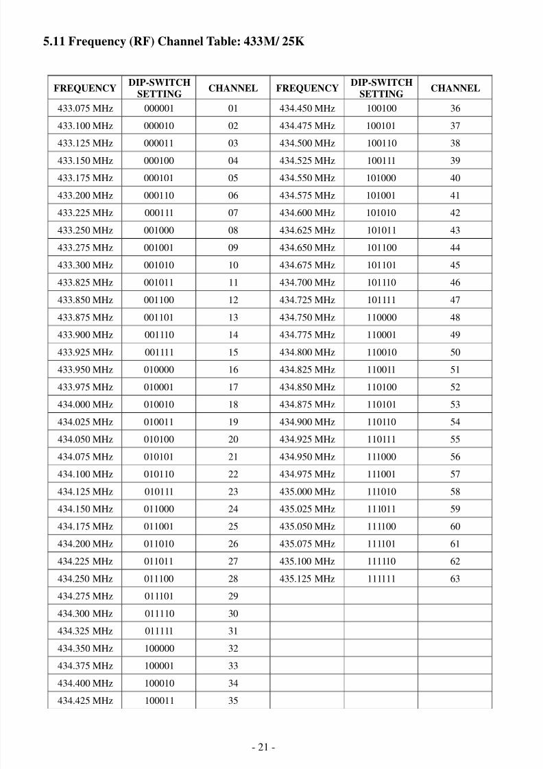
5.11 Frequency (RF) Channel Table: 433M/ 25K
FREQUENCYDIP-SWITCH
SETTINGCHANNEL FREQUENCY
DIP-SWITCH
SETTINGCHANNEL
433.075 MHz 000001 01 434.450 MHz 100100 36
433.100 MHz 000010 02 434.475 MHz 100101 37
433.125 MHz 000011 03 434.500 MHz 100110 38
433.150 MHz 000100 04 434.525 MHz 100111 39
433.175 MHz 000101 05 434.550 MHz 101000 40
433.200 MHz 000110 06 434.575 MHz 101001 41
433.225 MHz 000111 07 434.600 MHz 101010 42
433.250 MHz 001000 08 434.625 MHz 101011 43
433.275 MHz 001001 09 434.650 MHz 101100 44
433.300 MHz 001010 10 434.675 MHz 101101 45433.825 MHz 001011 11 434.700 MHz 101110 46
433.850 MHz 001100 12 434.725 MHz 101111 47
433.875 MHz 001101 13 434.750 MHz 110000 48
433.900 MHz 001110 14 434.775 MHz 110001 49
433.925 MHz 001111 15 434.800 MHz 110010 50
433.950 MHz 010000 16 434.825 MHz 110011 51
433.975 MHz 010001 17 434.850 MHz 110100 52
434.000 MHz 010010 18 434.875 MHz 110101 53
434.025 MHz 010011 19 434.900 MHz 110110 54
434.050 MHz 010100 20 434.925 MHz 110111 55
434.075 MHz 010101 21 434.950 MHz 111000 56
434.100 MHz 010110 22 434.975 MHz 111001 57
434.125 MHz 010111 23 435.000 MHz 111010 58
434.150 MHz 011000 24 435.025 MHz 111011 59
434.175 MHz 011001 25 435.050 MHz 111100 60
434.200 MHz 011010 26 435.075 MHz 111101 61
434.225 MHz 011011 27 435.100 MHz 111110 62
434.250 MHz 011100 28 435.125 MHz 111111 63
434.275 MHz 011101 29
434.300 MHz 011110 30
434.325 MHz 011111 31
434.350 MHz 100000 32
434.375 MHz 100001 33
434.400 MHz 100010 34
434.425 MHz 100011 35
8/6/2019 A4K Technical Manual_(080528)
http://slidepdf.com/reader/full/a4k-technical-manual080528 22/32 - 22 -
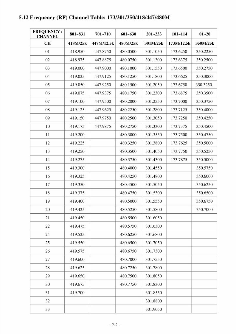
5.12 Frequency (RF) Channel Table: 173/301/350/418/447/480M
FREQUENCY /
CHANNEL801~831 701~710 601~630 201~233 101~114 01~20
CH 418M/25k 447M/12.5k 480M/25k 301M/25k 173M/12.5k 350M/25k
01 418.950 447.8750 480.0500 301.1050 173.6250 350.2250
02 418.975 447.8875 480.0750 301.1300 173.6375 350.2500
03 419.000 447.9000 480.1000 301.1550 173.6500 350.2750
04 419.025 447.9125 480.1250 301.1800 173.6625 350.3000
05 419.050 447.9250 480.1500 301.2050 173.6750 350.3250.
06 419.075 447.9375 480.1750 301.2300 173.6875 350.3500
07 419.100 447.9500 480.2000 301.2550 173.7000 350.3750
08 419.125 447.9625 480.2250 301.2800 173.7125 350.4000
09 419.150 447.9750 480.2500 301.3050 173.7250 350.4250
10 419.175 447.9875 480.2750 301.3300 173.7375 350.4500
11 419.200 480.3000 301.3550 173.7500 350.4750
12 419.225 480.3250 301.3800 173.7625 350.5000
13 419.250 480.3500 301.4050 173.7750 350.5250
14 419.275 480.3750 301.4300 173.7875 350.5000
15 419.300 480.4000 301.4550 350.5750
16 419.325 480.4250 301.4800 350.6000
17 419.350 480.4500 301.5050 350.6250
18 419.375 480.4750 301.5300 350.6500
19 419.400 480.5000 301.5550 350.6750
20 419.425 480.5250 301.5800 350.7000
21 419.450 480.5500 301.6050
22 419.475 480.5750 301.6300
24 419.525 480.6250 301.6800
25 419.550 480.6500 301.7050
26 419.575 480.6750 301.7300
27 419.600 480.7000 301.7550
28 419.625 480.7250 301.7800
29 419.650 480.7500 301.8050
30 419.675 480.7750 301.8300
31 419.700 301.8550
32 301.8800
33 301.9050
8/6/2019 A4K Technical Manual_(080528)
http://slidepdf.com/reader/full/a4k-technical-manual080528 23/32 - 23 -
6. TRANSMITTER OPERATION
6.1 Transmitter Operation
★ Make sure that the red emergency stop button (EMS) is elevated before the transmitter power is turned on.
1. Rotate the power switch: (Off) → (On) → (Start) to turn on the transmitter. The transmitter can be used
after the “power on” LED status display normally finished. Do not press any pushbutton when turn on the
transmitter.
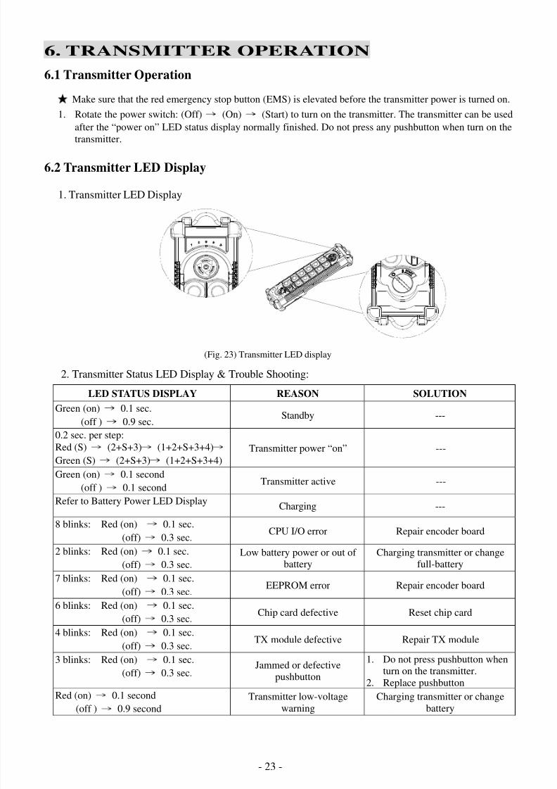
6.2 Transmitter LED Display
1. Transmitter LED Display
(Fig. 23) Transmitter LED display
2. Transmitter Status LED Display & Trouble Shooting:
LED STATUS DISPLAY REASON SOLUTION
Green (on) → 0.1 sec.
(off ) → 0.9 sec. Standby ---
0.2 sec. per step:
Red (S)→
(2+S+3)→
(1+2+S+3+4)→
Green (S)→
(2+S+3)→
(1+2+S+3+4)
Transmitter power “on” ---
Green (on)→
0.1 second
(off )→
0.1 secondTransmitter active ---
Refer to Battery Power LED DisplayCharging ---
8 blinks: Red (on) → 0.1 sec.
(off)→
0.3 sec.CPU I/O error Repair encoder board
2 blinks: Red (on)→
0.1 sec.(off)
→ 0.3 sec.
Low battery power or out of battery
Charging transmitter or changefull-battery
7 blinks: Red (on)→
0.1 sec.
(off)→
0.3 sec.EEPROM error Repair encoder board
6 blinks: Red (on)→
0.1 sec.
(off)→
0.3 sec.Chip card defective Reset chip card
4 blinks: Red (on)→
0.1 sec.
(off)→
0.3 sec.TX module defective Repair TX module
3 blinks: Red (on)→
0.1 sec.
(off)→
0.3 sec.Jammed or defective
pushbutton
1. Do not press pushbutton when
turn on the transmitter.
2. Replace pushbutton
Red (on)→
0.1 second
(off )→
0.9 second
Transmitter low-voltage
warning
Charging transmitter or change
battery

8/6/2019 A4K Technical Manual_(080528)
http://slidepdf.com/reader/full/a4k-technical-manual080528 24/32 - 24 -
N
Note: POS = Power Off Stop: When set the power switch to (Off) position, it will transmit “Stop” codes.
6.3 Transmitter LED Display
(Fig. 24)
LED STATUS DISPLAY REASON SOLUTION
5 blinks: Red (on) → 0.1 sec.
(off)→
0.3 sec.
No Chip card is inserted
- Insert programmed chip card or
refer to 1.
- Chip card defective:
1. Insert short pin into J1, the
transmitter can be used without
chip card. When use by chip card,
J1 must removed.
2. Replace new and programmedchip card.
Insert short pin into J2 jumper and
replace a new chip card. Then turn
on the power source, CPU will
copy data on the chip card. When
all five LED status display green(on), remove J2 pin.
Emergency stop or POS function
started (refer to note)---
Red (on)→
0.1 second
(off )→
0.1 second
Emergency stop with pressing
pushbuttonor pushbuttons jammed
---
0.5 sec. per step:
Green (1)→
(1+2)→
(1+2+S)→
(1+2+S+3)→
(1+2+S+3+4)
Update the chip card ---
0.5 sec. per step:
Green (4) → (3+4) → (S+3+4) →
(2+S+3+4) → (1+2+S+3+4)
Copy CPU data to chip card
1. All LED will display green (on)
when write data in chip card is
finished. Then remove J2 pin, the
transmitter can be used.
2. Any LED will display red (on)
when write data in chip card is
defective. Turn off the transmitterand try again or change new chip
card.
Check transmitter outline:A. Check the transmitter enclosure and pushbutton rubber boot. If damaged, enclosure and
pushbutton rubber boot should be replaced.B. Always keep the battery terminals clean.
C. Check if there is ample batter charge: Turn the transmitter on and check if the LED displays
“S” blinking green.
3. Loading the battery: Remove the battery cover screws which on the back of transmitter and load
the battery.
8/6/2019 A4K Technical Manual_(080528)
http://slidepdf.com/reader/full/a4k-technical-manual080528 25/32 - 25 -
7. RECEIVER INSTALLATION
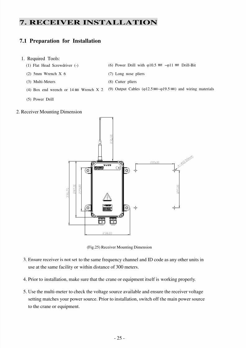
7.1 Preparation for Installation
2. Receiver Mounting Dimension
(Fig.25) Receiver Mounting Dimension
3. Ensure receiver is not set to the same frequency channel and ID code as any other units in
use at the same facility or within distance of 300 meters.
4. Prior to installation, make sure that the crane or equipment itself is working properly.
5. Use the multi-meter to check the voltage source available and ensure the receiver voltage
setting matches your power source. Prior to installation, switch off the main power source
to the crane or equipment.
1. Required Tools:(1) Flat Head Screwdriver (-) (6) Power Drill with φ10.5 ㎜ ~φ11 ㎜ Drill-Bit
(2) 5mm Wrench X 6 (7) Long nose pliers
(3) Multi-Meters (8) Cutter pliers
(4) Box end wrench or 14㎜
Wrench X 2
(5) Power Drill
(9) Output Cables (φ12.5㎜
~φ19.5㎜
) and wiring materials

8/6/2019 A4K Technical Manual_(080528)
http://slidepdf.com/reader/full/a4k-technical-manual080528 26/32 - 26 -
7.2 Step-by-Step Receiver Installation
1. Select a suitable location to mount the receiver.
2. As much as possible, the location selected should be has the antenna visible from all area
s where the transmitter is to be used.
3. The location selected should not be exposed to high levels of electric noise.
4. Ensure the selected location has adequate space to accommodate the receiver enclosure.
5. The distance between the antenna and the control panel should be as far as possible.
6. Drill four holes on the control panel (10.50mm)
7. Tighten all screws provided.
8. Ensure AC ground is connected to the power input terminal block otherwise chassis groun
d should be connected to the chassis ground connection hole on the receiver enclosure.
9. Ensure all wiring is correct and safely secured and all screws are fastened.
(Fig. 26) Receiver mounting size
8/6/2019 A4K Technical Manual_(080528)
http://slidepdf.com/reader/full/a4k-technical-manual080528 27/32 - 27 -
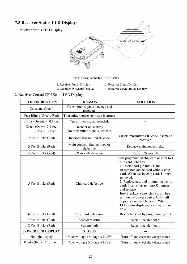
7.3 Receiver Status LED Displays
1. Receiver Status LED Display
(Fig 27) Receiver Status LED Display
2. Receiver Central CPU Status LED Display
LED INDICATION REASON SOLUTION
Constant (Green)Transmitted signals detected and
received.---
Fast Blinks (Green/ Red) Transmitter power (on) step incorrect
Blinks (Green) → 0.1 sec. Transmitted signal decoded. ---
Green (On)→
0.1 sec.
(Off)→
0.8 sec.
Decoder on standby
(No transmitted signals detected)---
2 Fast Blinks (Red) Incorrect transmitted ID code
Check transmitter’s ID code if same to
receiver.
3 Fast Blinks (Red)Main contact relay jammed or
defectiveReplace main contact relay
4 Fast Blinks (Red) RX module defective Repair RX module
5 Fast Blinks (Red) Chip card defective
Insert programmed chip card or refer to 1.
- Chip card defective:
1. Insert short pin into J1, the
transmitter can be used without chip
card. When use by chip card, J1 must
removed.
2. Replace new and programmed chip
card. Insert short pin into J2 jumperand replace
Insert replace a new chip card. Then
turn on the power source, CPU will
copy data on the chip card. When all
LED status display green (on), remove
J2 pin.
6 Fast Blinks (Red) Chip card data error Reset chip card by programming tool
7 Fast Blinks (Red) EEPORM error Repair decoder board
8 Fast Blinks (Red) System fault Repair decoder board
POWER LED DISPLAY STATUS ---
No light display Under-voltage ( voltage < 10.5V) Turn off and check the voltage source
Blinks (Red)→
0.1 sec. Over-voltage (voltage > 16V) Turn off and check the voltage source
1. Receiver Power Display 3. Receiver Status Display
2. Receiver SQ Status Display 4. Receiver MAIN Relay Display
8/6/2019 A4K Technical Manual_(080528)
http://slidepdf.com/reader/full/a4k-technical-manual080528 28/32 - 28 -
8. BATTERYCHARGING &LED DISPALY
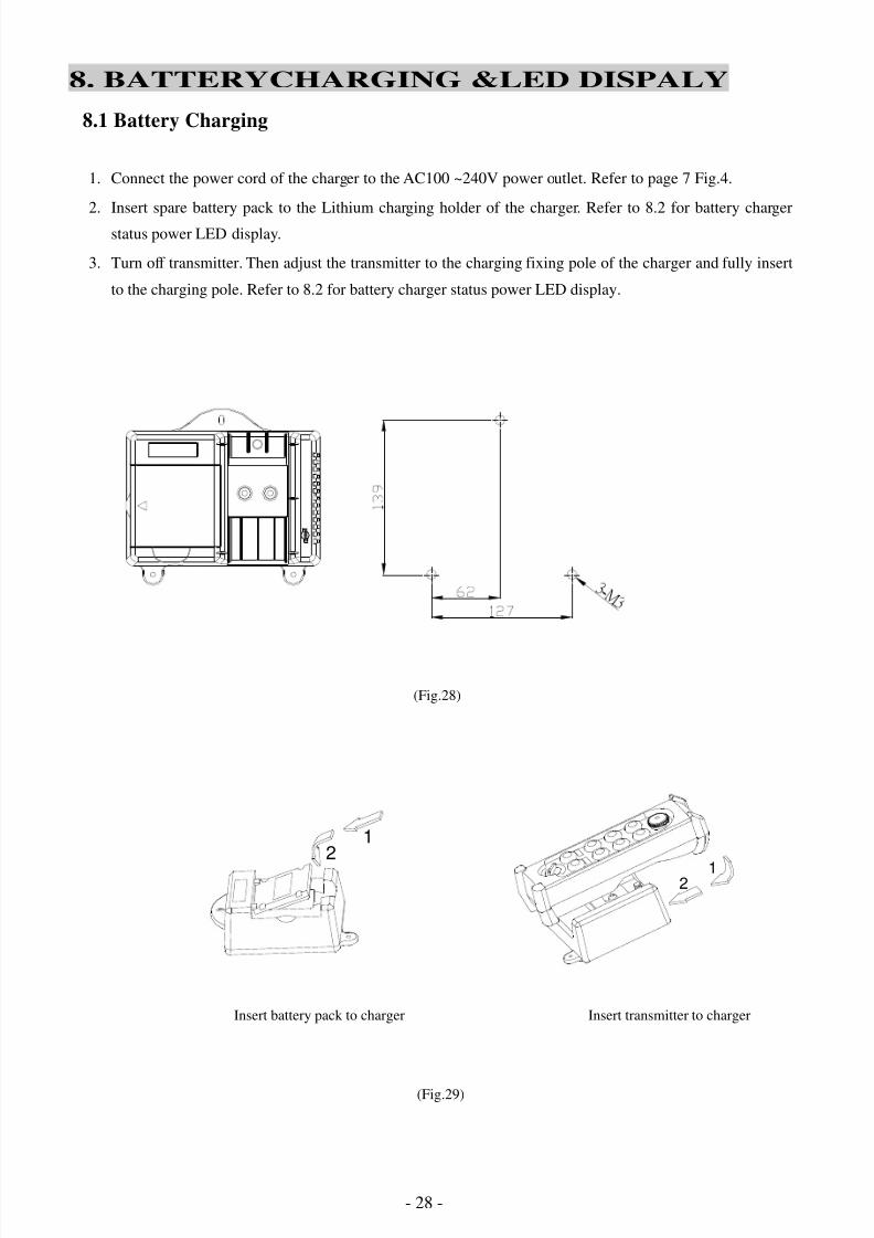
8.1 Battery Charging
1. Connect the power cord of the charger to the AC100 ~240V power outlet. Refer to page 7 Fig.4.
2. Insert spare battery pack to the Lithium charging holder of the charger. Refer to 8.2 for battery charger
status power LED display.
3. Turn off transmitter. Then adjust the transmitter to the charging fixing pole of the charger and fully insert
to the charging pole. Refer to 8.2 for battery charger status power LED display.
3
-
M
3
(Fig.28)
Insert battery pack to charger Insert transmitter to charger
(Fig.29)
21
12
8/6/2019 A4K Technical Manual_(080528)
http://slidepdf.com/reader/full/a4k-technical-manual080528 29/32 - 29 -
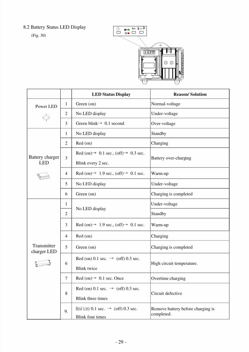
8.2 Battery Status LED Display
(Fig. 30)
LED Status Display Reason/ Solution
1 Green (on) Normal-voltage
2 No LED display Under-voltage
Power LED
3 Green blink → 0.1 second Over-voltage
1 No LED display Standby
2 Red (on) Charging
3Red (on)
→ 0.1 sec., (off)
→ 0.3 sec.
Blink every 2 sec.Battery over-charging
4 Red (on) → 1.9 sec., (off) → 0.1 sec. Warm-up
5 No LED display Under-voltage
Battery charger
LED
6 Green (on) Charging is completed
1 Under-voltage
2No LED display
Standby
3 Red (on) → 1.9 sec., (off) → 0.1 sec. Warm-up
4 Red (on) Charging
5 Green (on) Charging is completed
6Red (on) 0.1 sec.
→ (off) 0.3 sec.
Blink twiceHigh circuit temperature.
7 Red (on)→
0.1 sec. Once Overtime charging
Transmittercharger LED
8Red (on) 0.1 sec. → (off) 0.3 sec.
Blink three timesCircuit defective
9.R e d ( o n ) 0.1 sec. → (off) 0.3 sec.
Blink four times
Remove battery before charging iscompleted.
8/6/2019 A4K Technical Manual_(080528)
http://slidepdf.com/reader/full/a4k-technical-manual080528 30/32 - 30 -
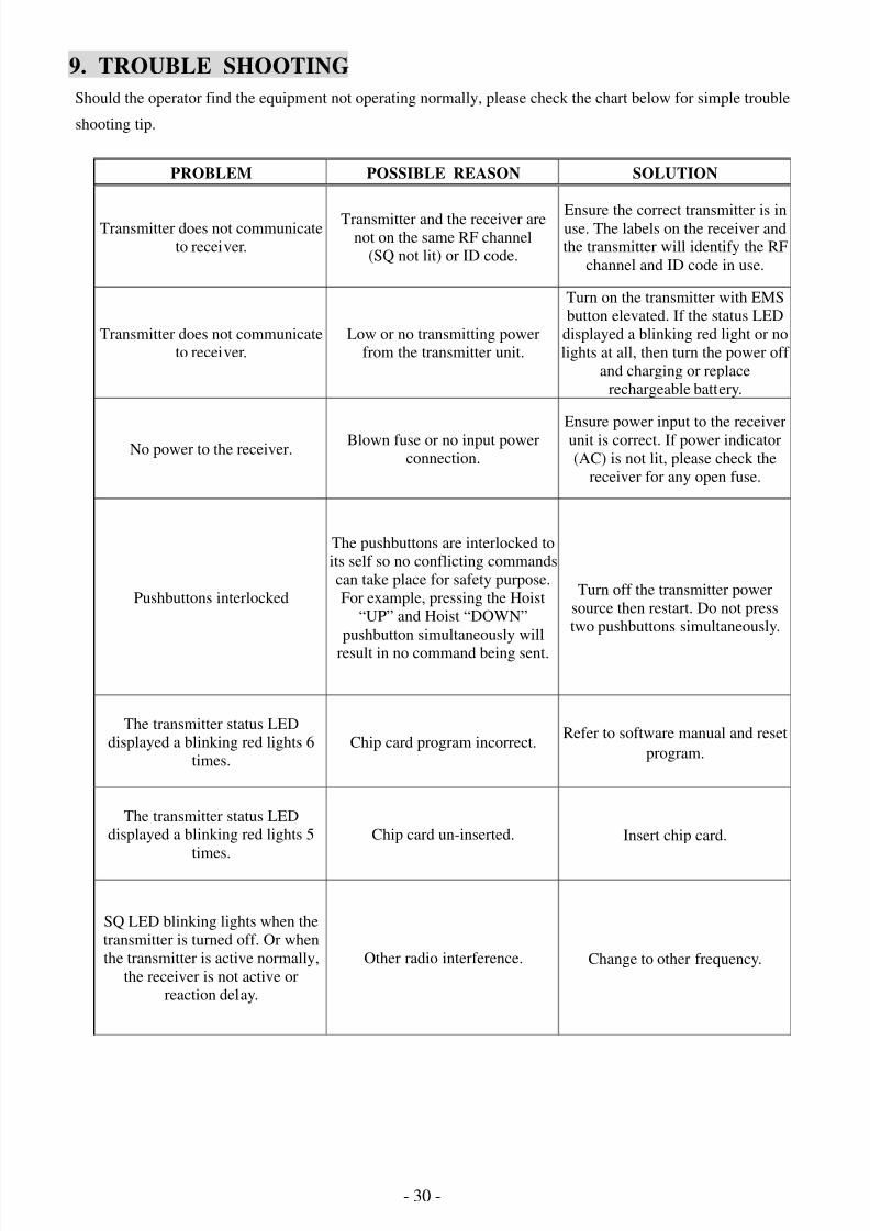
9. TROUBLE SHOOTING
Should the operator find the equipment not operating normally, please check the chart below for simple trouble
shooting tip.
PROBLEM POSSIBLE REASON SOLUTION
Transmitter does not communicate
to receiver.
Transmitter and the receiver arenot on the same RF channel
(SQ not lit) or ID code.
Ensure the correct transmitter is inuse. The labels on the receiver and
the transmitter will identify the RF
channel and ID code in use.
Transmitter does not communicate
to receiver.
Low or no transmitting power
from the transmitter unit.
Turn on the transmitter with EMS
button elevated. If the status LED
displayed a blinking red light or no
lights at all, then turn the power off
and charging or replace
rechargeable battery.
No power to the receiver.Blown fuse or no input power
connection.
Ensure power input to the receiver
unit is correct. If power indicator
(AC) is not lit, please check the
receiver for any open fuse.
Pushbuttons interlocked
The pushbuttons are interlocked to
its self so no conflicting commands
can take place for safety purpose.
For example, pressing the Hoist
“UP” and Hoist “DOWN”
pushbutton simultaneously will
result in no command being sent.
Turn off the transmitter power
source then restart. Do not press
two pushbuttons simultaneously.
The transmitter status LED
displayed a blinking red lights 6
times.
Chip card program incorrect.Refer to software manual and reset
program.
The transmitter status LED
displayed a blinking red lights 5
times.
Chip card un-inserted. Insert chip card.
SQ LED blinking lights when the
transmitter is turned off. Or when
the transmitter is active normally,
the receiver is not active or
reaction delay.
Other radio interference. Change to other frequency.
8/6/2019 A4K Technical Manual_(080528)
http://slidepdf.com/reader/full/a4k-technical-manual080528 31/32 - 31 -
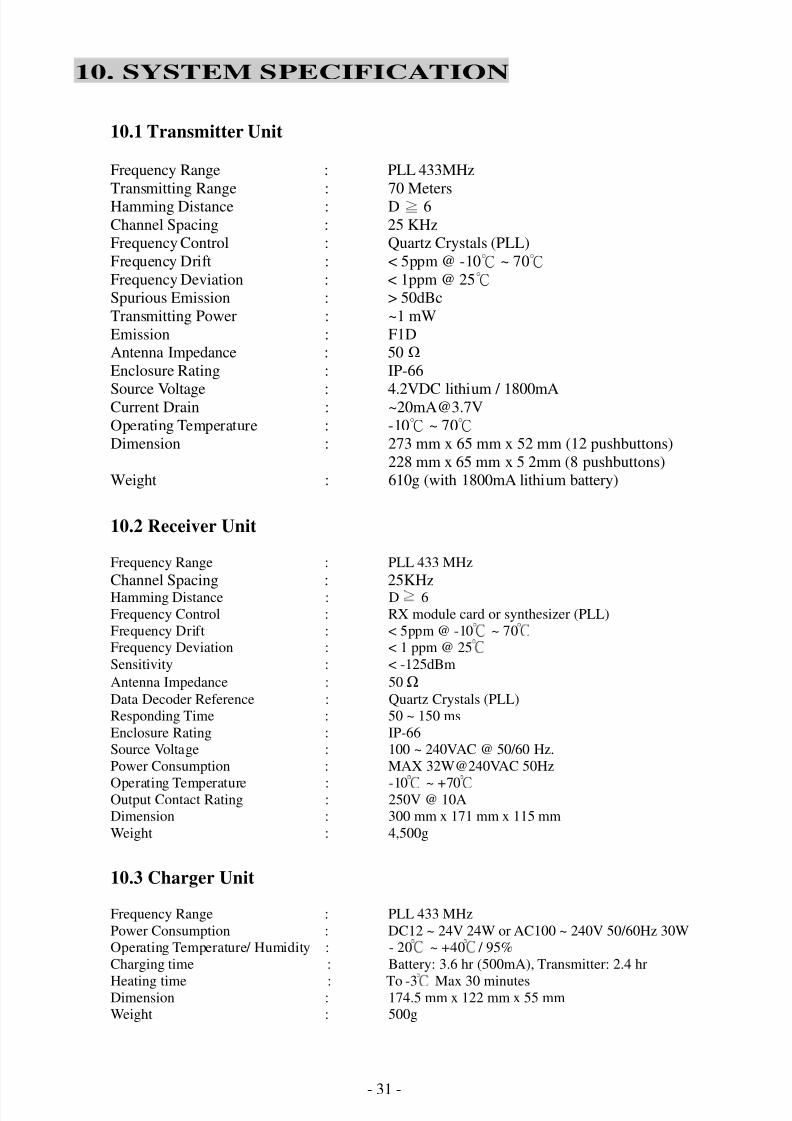
10. SYSTEM SPECIFICATION
10.1 Transmitter Unit
Frequency Range : PLL 433MHz
Transmitting Range : 70 MetersHamming Distance : D ≧ 6
Channel Spacing : 25 KHz
Frequency Control : Quartz Crystals (PLL)
Frequency Drift : < 5ppm @ -10 ~ 70℃ ℃
Frequency Deviation : < 1ppm @ 25℃
Spurious Emission : > 50dBc
Transmitting Power : ~1 mW
Emission : F1DAntenna Impedance : 50
Enclosure Rating : IP-66
Source Voltage : 4.2VDC lithium / 1800mACurrent Drain : [email protected]
Operating Temperature : -10 ~ 70℃ ℃
Dimension : 273 mm x 65 mm x 52 mm (12 pushbuttons)
228 mm x 65 mm x 5 2mm (8 pushbuttons)
Weight : 610g (with 1800mA lithium battery)
10.2 Receiver Unit
Frequency Range : PLL 433 MHz
Channel Spacing : 25KHzHamming Distance : D 6≧
Frequency Control : RX module card or synthesizer (PLL)
Frequency Drift : < 5ppm @ -10 ~ 70℃ ℃
Frequency Deviation : < 1 ppm @ 25℃
Sensitivity : < -125dBm
Antenna Impedance : 50
Data Decoder Reference : Quartz Crystals (PLL)
Responding Time : 50 ~ 150 ms
Enclosure Rating : IP-66
Source Voltage : 100 ~ 240VAC @ 50/60 Hz.
Power Consumption : MAX 32W@240VAC 50Hz
Operating Temperature : -10 ~ +70℃ ℃
Output Contact Rating : 250V @ 10A
Dimension : 300 mm x 171 mm x 115 mm
Weight : 4,500g
10.3 Charger Unit
Frequency Range : PLL 433 MHz
Power Consumption : DC12 ~ 24V 24W or AC100 ~ 240V 50/60Hz 30W
Operating Temperature/ Humidity : - 20 ~ +40℃ ℃
/ 95%
Charging time : Battery: 3.6 hr (500mA), Transmitter: 2.4 hr
Heating time : To -3℃
Max 30 minutesDimension : 174.5 mm x 122 mm x 55 mm
Weight : 500g
8/6/2019 A4K Technical Manual_(080528)
http://slidepdf.com/reader/full/a4k-technical-manual080528 32/32
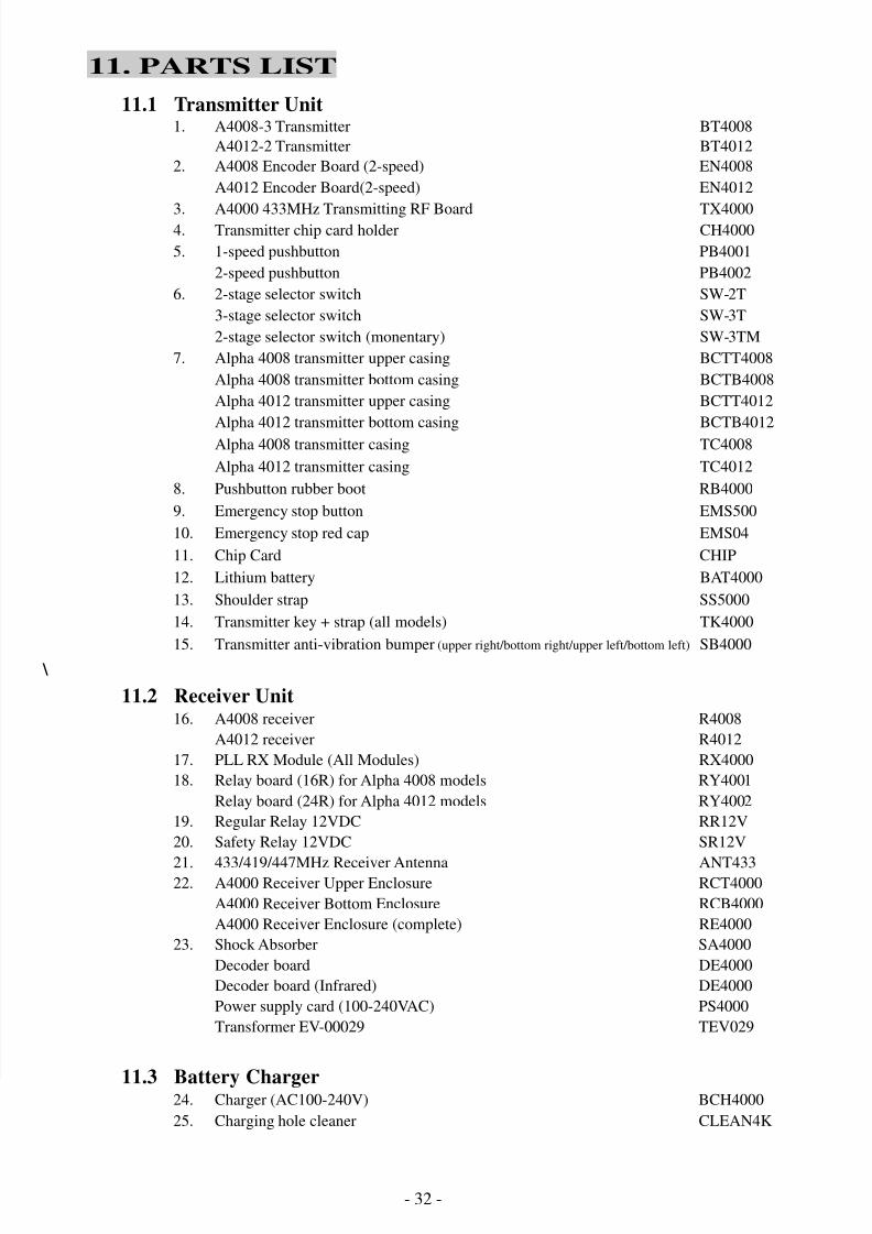
11. PARTS LIST
11.1 Transmitter Unit1. A4008-3 Transmitter BT4008
A4012-2 Transmitter BT4012
2. A4008 Encoder Board (2-speed) EN4008
A4012 Encoder Board(2-speed) EN4012
3. A4000 433MHz Transmitting RF Board TX40004. Transmitter chip card holder CH4000
5. 1-speed pushbutton PB4001
2-speed pushbutton PB4002
6. 2-stage selector switch SW-2T
3-stage selector switch SW-3T
2-stage selector switch (monentary) SW-3TM
7. Alpha 4008 transmitter upper casing BCTT4008
Alpha 4008 transmitter bottom casing BCTB4008
Alpha 4012 transmitter upper casing BCTT4012
Alpha 4012 transmitter bottom casing BCTB4012
Alpha 4008 transmitter casing TC4008
Alpha 4012 transmitter casing TC4012
8. Pushbutton rubber boot RB4000
9. Emergency stop button EMS500
10. Emergency stop red cap EMS04
11. Chip Card CHIP
12. Lithium battery BAT4000
13. Shoulder strap SS5000
14. Transmitter key + strap (all models) TK4000
15. Transmitter anti-vibration bumper (upper right/bottom right/upper left/bottom left) SB4000 \
11.2 Receiver Unit16. A4008 receiver R4008
A4012 receiver R4012
17. PLL RX Module (All Modules) RX4000
18. Relay board (16R) for Alpha 4008 models RY4001
Relay board (24R) for Alpha 4012 models RY4002
19. Regular Relay 12VDC RR12V
20. Safety Relay 12VDC SR12V
21. 433/419/447MHz Receiver Antenna ANT43322. A4000 Receiver Upper Enclosure RCT4000
A4000 Receiver Bottom Enclosure RCB4000
A4000 Receiver Enclosure (complete) RE4000
23. Shock Absorber SA4000
Decoder board DE4000
Decoder board (Infrared) DE4000
Power supply card (100-240VAC) PS4000
Transformer EV-00029 TEV029
11.3 Battery Charger24. Charger (AC100-240V) BCH4000