Embed Size (px)
Citation preview
A New 3D Display Using a Dynamically Reconfigurable
Display Matrix Surface
†Daqing Xue, ‡Darrell Wallace, †Roger Crawfis
The Ohio State University, Columbus, OH 43210, USA
ABSTRACT
This paper presents a new three-dimensional display system using a reconfigurable projection manifold. The display surface is warped interactively into a non-planar manifold according to the scene image’s depth information for the current view. Scene images are projected onto the display using computer graphics and a post-process warping. We currently use two projections to provide a complete coverage of the manifold surface from oblique projection angles. In this paper, we describe the overall design issues and goals of the projector-based rendering process, introduce the algorithms to model the projection manifold surface and describe the algorithms used to create the pre-warped images from the scene image. Our current prototype is a discrete tile-based approximation to the depth manifold. We describe our experiments with two such prototypes, one using a static test configuration, and another actuated using linear motion controllers for each discrete tile. This second prototype can be configured dynamically, as the depth information in the scene changes.
CR Categories and Subject Descriptors: I.3.3 [Computer Graphics]: Picture/Image Generation – Display Algorithms, Viewing Algorithms; I.3.7 [Computer Graphics]: Three-Dimensional Graphics and Realism.
Keywords: 3D display, multi-projector, image warping, spatially immersive display, motion parallax.
1. INTRODUCTION
The use of projectors to reintroduce real scenes has been a focus in the graphics community for many years. Contrary to the direct and expensive replica building of famous scenes such as in Walt Disney World’s Epcot Center in Orlando (USA) or the World Park in Beijing (China), computer graphics researchers prefer to provide an applicable and economic solution to reproduce a scene using three-dimensional computer graphics and virtual reality techniques [1,2,4,5,17,19]. As stated in [5], the main components of a spatially immersive display system typically include:
1) Scene modeling. This is the process to capture the scene with geometric information.
2) Display surface modeling and construction. The physical model is constructed and its display surface is modeled to receive the image projection.
3) Projector placement and calibration. The projectors are placed appropriately to fit the physical model and the user’s application. The projectors need to be calibrated to determine their geometric relation to the physical model.
4) Geometrical Registration. Due to overlapping of projectors and camera feedback tracking, both projectors and cameras must be registered to maintain geometrical integrity.
5) Tracking. The user’s eye is tracked to create the correct view dependent image.
6) Rendering. Rendering is an inverse process to casting the image on the display surface and it accounts for creating the correctly distorted images.
Scene modeling accounts for capturing a scene image with geometrical information (depth in our display system). It can be achieved either by creating a synthetic model in OpenGL or some other commercial software like Bryce4 [14] or by extracting the depth information from the taken scene pictures [13]. The ideal digital projector can be modeled as a pinhole camera and its calibration with the physical model is addressed in [9, 10, 15] by solving the projection matrix with respect to the labeled feature points.
In this paper we present a tile-based, three-dimensional, display system with a reconfigurable display matrix surface. Unlike the traditional displays which are typically planar, or piecewise planar in the case of the CAVE [4], our reconfigurable display is built out of a matrix of tiles. Each of these tiles can be repositioned to form a basic projected shape. Projected imagery fills in the details for a three dimensional view without the need for single person stereo. We develop the algorithms to model the discontinuous, tile-wise display surface to simulate the modeled scene shape, and warp the resulting scene imagery using an OpenGL texture mapping technique to create the correct projection onto the non-planar display surface. To dynamically manipulate the scene, we also develop a set of linear motion controllers for our display matrix.
The remainder of this paper is organized as follows. Section 2 examines related work in spatially immersive displays and three-dimensional displays. Section 3 describes the ideas and the implementation details of our rendering process. The algorithms for modeling the display surface and warping the scene image are provided. In section 4, we describe the servo-motor driver controls for the display matrix. In section 5, we present results and discuss the advantages and limitations of our 3D display. In section 6 we draw conclusions from our work.
† Email: {xue | crawfis}@cse.ohio-state.edu ‡ Email: [email protected]
2. RELATED WORK
2.1 Spatially Immersive Displays
The CAVETM presented by Cruz-Neira et al. [4] is probably the most well-known spatially immersive display (SID) system in the graphics community. Their initial CAVETM configuration includes the left, right, and front walls with rear projectors and the floor using a front projector. Each projector in the CAVETM
projects an image on the planar surfaces (left, right, and front walls, and the floor). The CAVETM obtains walk-through effects for an active viewer by tracking the user’s head position and updating the projected images on the walls accordingly.
Raskar et al. [2] introduce the concept of the “office of the future” and explore some implementation details like imperceptible structured light. Their goal is to realize the spatially immersive display in “anywhere in the office”. The general day-to-day surfaces like the walls, desk area, and tables in the office could be used as parts of the display surface. They also use a head-tracking device to determine the viewer’s position to provide the view-dependent image. Their focus is to adjust the imagery to remove the distortions caused by the non-planar surface. This provides a flat desktop. Such system can be used for entertainment like projecting the video on the curtained window [24]. Our system examines the reverse process, that of distorting the display surface and the imagery to provide a 2.5D view.
Both of these displays require stereo rendering using liquid crystal shutter glasses, which limits simultaneous viewing in a multi-user setting.
Nakatani et al. [23] developed a similar display matrix to display 3D objects by orchestrating the vertical motion of a dense array of pin-rods. They demonstrated the concept and their results in their “Popup” videos†.
2.2 True 3D Displays
An alternative for the spatially immersive display is to build a physical model as presented by Raskar et al [1] and Low et al. [5]. They both construct static physical models, one of a miniature Taj Mahal, the other a life-sized room, that approximate the shapes of objects with neutral (white) colored materials. Shader lamps [1], the computer-controlled projectors, are used to map detail textures on the surface of the models, providing a virtual painting application. The viewer’s eyes are tracked to provide view dependent illumination, such as specular highlights.
An emmetropic (normal) human eye views an object clearly in real space by both adjusting the eye’s focus (accommodation) to eliminate blur and changing the relative eye’s position (vergence) to remove double vision. Accommodation and vergence are coupled to achieve stereovision. The common stereoscopic displays like a head-mounted display (HMD) provide two disparate perspective views to achieve a perception of depth without coupling the two perceptual processes, accommodation and vergence. This causes an unnatural experience of true depth. Traub [18], Fuchs [19] and Johnson [20] introduced a varifocal mirror to stimulate the viewer eye’s accommodation and vergence
† http://www.star.t.u-tokyo.ac.jp/projects/popup/movie/concept.mpg, http://www.star.t.u-tokyo.ac.jp/projects/popup/movie/displaying_popup.mpg.
to obtain a truly three-dimensional display. One drawback is that nearer objects cannot occlude the more distant ones. McQuaide et al. [8] present a deformable membrane mirror to generate multiple focal planes achieving a monocular 3D display. They use a virtual retinal display (VRD) [17], in which an image is directly scanned on the retina of the viewer’s eye via a laser beam. A more attractive true 3D display is holographic stereograms [21]. In a holographic stereogram, a sequence of views (usually more than 100) from slightly differing side-to-side viewpoints images are projected onto the holographic film with laser interference. After exposure and processing, the viewer will see a solid object or 3D scene floating in the vicinity of the film. However, the large computation to generate view-dependent images and the exposure time make it impractical for interactive display. Combining holograms with interactive computer graphics to provide augmented reality is an emerging technique [25].
3. RENDERING PROCESS
3.1 System Overview
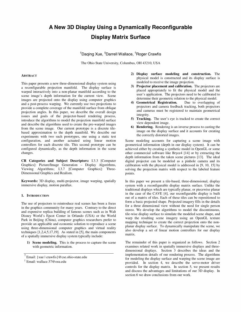
Figure 1 shows the diagrams of rendering process and the physical configuration of our display system. The display matrix surface consists of an m×n set of square tiles (see figure 1b). To reproduce an approximation to the real scene on such tile-wise 3D display, a desired image with depth information is used as the input reference image to be warped and projected onto the display. We dealt strictly with computer generated scenes in this paper, so an accurate depth is easily obtainable. From the depth information, the display surface is configured to roughly match the scene’s shape. The reference scene image is then mapped onto the non-planar display surface to simulate the scene. Here, we assume the viewpoint to the center of the display surface is with that of the camera which captured the depth. Since we want to place a walking area for the viewer in the very front of the display surface, the projector must be placed aside from the walking area. Thus the reference image must be warped before cast onto the surface, such that the user in the center of the walking area still sees a geometrically correct scene.
Figure 1b shows the physical configuration of our 3D display system. The display surface is configured to approximate the
Scene image
Display matrix surface
Scene model
Motion linear controller
Zbuffer/ Depth image
Reference image
Warped image projection
Render from projector
Render from camera
(a)
Walking area
left projector
right projector
tile
viewpoint
Display Matrix
(b)
Figure 1: (a) The system overview diagram. (b) The top view of the tile-wise 3D display system
geometric profile. The scene image is warped and projected onto the tiles of the display surface from the left projector. The right projector is used to remove shadows produced from the left projector due to tile occlusions. The viewer at the center of the walking area sees a truly three-dimensional representation of the scene on the non-planar display wall. A stereo or three-dimensional view of the world is easily obtained by the user moving his or her head slightly from side to side, providing a nice motion parallax effect coupled with occlusion.
We will describe the following three aspects of our system in details: display surface modeling, scene image warping, and shadow removal.
3.2 Display Surface Modeling
In the surface modeling in [2, 4, 12], the display surfaces are not related to the scene model, but are solely modeled to correct distortions arising from the projection on the non-planar display surface. The purpose of our display surface modeling is to create an approximation to the scene geometry according to the depth information from the scene image. The viewer at the viewpoint in the walking area (figure 1b) can be imagined as a virtual camera.
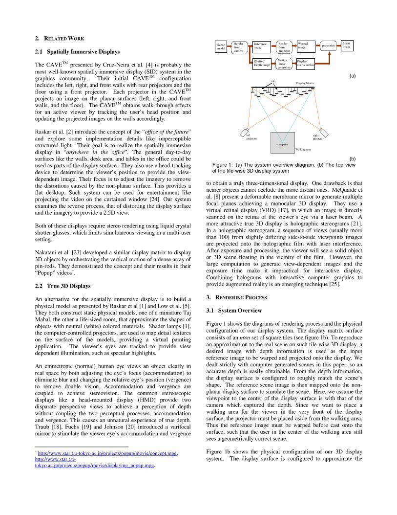
The scene image is evenly divided into the same number of tiles as the display matrix surface. For each tile, we calculate its average depth from its counterpart in the depth image. Then the tile on the display is extended according to this depth. For the virtual camera at the viewpoint, the change in the depth of the tile generates a different projection of the scene image. The tile depth must be changed due to this new set of pixels. This is an iterative process and is repeated until the tile depth converges to a fixed point. We developed an iterative algorithm to determine the tile depth and partition the scene image. Our experiment shows that usually no more than 10 iteration steps are necessary to achieve a tile’s stable position. The algorithm for this is listed below:
Figure 2 shows the resulting images from determining the tile depth of a scene with an obliquely placed torus. The tile images are framed to indicate their projections on the scene image. The tile highlighted with a bold red border clearly demonstrates the iterative depth solution. Its depth converges to a fixed position after 8 iterations. The algorithm generates texture mapping coordinates for each tile, such that the proper set of pixels from the rendered image is cast onto the tile.
3.3 Scene Image Warping
This depth mapping and projection works well, provided the projection is perpendicular to the display tiles. However, we want the display to be perpendicular to the viewer line of sight as much as possible. This limits the placement of the projectors. In our system, the solution is to place the projector on the left side of the walking area as in figure 1b. As other research has pointed out, the resulting image can be pre-warped to account for this distorted projection for both planar surfaces and non-planar surfaces [1, 2, 12]. For the case of a piece-wise approximation to the scene’s depth function, we are faced with two more problems: 1) mapping the image to the distorted and even discontinuous projection surfaces; 2) dealing with occlusion problems resulting from the oblique projection and non-planar display surface. The reference scene image is pre-distorted such that, when cast from the projector’s viewpoint onto the display wall, it still looks correct to
1) Initialize all tiles on the display wall with depth -1; 2) Set a virtual camera at the center of the walking area; 3) Render each tile of the display matrix to the virtual
camera; 4) Assign each tile with the scene image portion according
to its position in the frame buffer; 5) Calculate the tile depth from its mapped scene image
portion; 6) Repeat 3)-5) until all tiles reach stable positions.
(a) (b) (c) step=1, d = -0.70 (d) step=2, d=-0.86
(e) step=3, d = -0.77 (f) step=4, d=-0.83 (g) step=6, d = -0.81 (h) step=8, d=-0.81
Figure 2: The iterative process to determine the tile average depth from the texture image it covers. (a) and (b) are the scene and its depth images. (c)-(h) are the image partitions for different steps. The depth of the tile with bold red border is labeled below for each step.
the viewer in the center of the walking area. The right projector is used to remove the shadows due to the non-planar multi-surface display. We will discuss the details for shadow removal in section 3.4.
Many image warping techniques can be performed to generate the desired distorted image. Projective texture mapping was introduced by Segal et al. [6] to generate shadows and lighting effects; Debevec et al. [7] use projective texture mapping to create the view dependent texture for image based rendering and Raskar et al. [12] applied it to create the warped image implicitly for their multi-surfaces. For projective 2D texture mapping, the 3-component homogeneous coordinate (s,t,q) is provided for each primitive, and the interpolated homogeneous coordinate is projected to a real 2D texture coordinate, (s/q, t/q), used to index into the texture image. However, in our algorithm, we have obtained the texture image portion for each tile. We can thus provide the 2-component real coordinate (s,t) in texture space to index into the texture image directly. Our current implementation uses conventional 2D texture mapping in OpenGL to create the distorted scene image efficiently from the initial reference scene image.
In Section 3.2, we discussed how to build the tile-wise display surface model from the reference scene depth image. Now we can imagine the left projector renders these tiles mapped with their desired image coordinates to create the warped image. The warping is achieved tile by tile with OpenGL texture mapping. No explicit warping function is involved for an individual tile. However, these tiles overlap, resulting in occlusions. Hence, we do not have a continuous warping, but a disjoint reprojection. Since the tiles are occluded, they must be sorted according to their depth and rendered in a back-to-front order to obtain the correctly distorted image.
From the above discussion, we obtain the pseudo code for our warping algorithm as following:
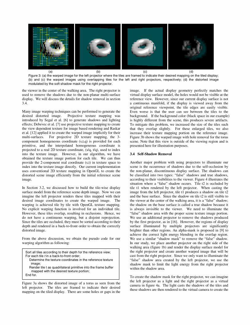
Figure 3a shows the distorted image of a torus as seen from the left projector. The tiles are framed to indicate their desired mapping on the tiled display. There are some holes or gaps in the
image. If the actual display geometry perfectly matches the virtual display surface model, the holes would not be visible at the reference view. However, since our current display surface is not a continuous manifold, if the display is viewed away from the original reference viewpoint, the tile edges are easily visible. Even worse is that the user can see between the tiles to the background. If the background color (black space in our example) is highly different from the scene, this produces severe artifacts. To mitigate this problem, we increased the size of the tiles such that they overlap slightly. For these enlarged tiles, we also increase their texture mapping portion on the reference image. Figure 3b shows the warped image with hole removal for the torus scene. Note that this view is outside of the viewing region and is presented here for illustration purposes.
3.4 Self-Shadow Removal
Another major problem with using projectors to illuminate our scene is the occurrence of shadows due to the self-occlusion by the non-planar, discontinuous display surface. The shadows can be classified into two types: “false” shadows and true shadows, according to their visibilities to the viewer. Figure 4 illustrates the situation where a “false” shadow occurs. Tile t2 is occluded by tile t1 when rendered by the left projector. When casting the image from the left projector, tile t1 produces a shadow on tile t2 and the base surface. Since the shadow on tile t2 is still visible to the viewer at the center of the walking area, it is a “false” shadow; the shadow on the base surface is called a true shadow because it is always invisible to the viewer. We need to illuminate the “false” shadow area with the proper scene texture image portion. We use an additional projector to remove the shadows produced by the first projector, as in [16]. However, the regions of display surface illuminated by multiple projectors are significantly brighter than other regions. An alpha-mask is proposed in [9] to achieve the correct light energy blending in the overlap region. We use a similar “shadow mask” to remove the “false” shadow. In our study, we place another projector on the right side of the walking area (figure 1b) and render the display surface model for the right projector and create another warped image that will be cast from the right projector. Since we only want to illuminate the “false” shadow area created by the left projector, we use the shadow mask to limit the light energy from the right projector within the shadow area.
To create the shadow mask for the right projector, we can imagine the left projector as a light and the right projector as a virtual camera in figure 4a. The light casts the shadows of the tiles and these shadows are then rendered to the virtual camera to create the
Sort all tiles according to their depth for the reference view; For each tile t in a back-to-front order;
Determine the texture coordinates in the reference texture image;
Render tile t as quadrilateral primitive into the frame buffer mapped with the desired texture portion;
End for.
(a) (b) (c) (d) Figure 3: (a) the warped image for the left projector where the tiles are framed to indicate their desired mapping on the tiled display; (b) and (c) the warped images using overlapping tiles for the left and right projectors, respectively; (d) the distorted image modulated by the soft shadow mask for the right projector.
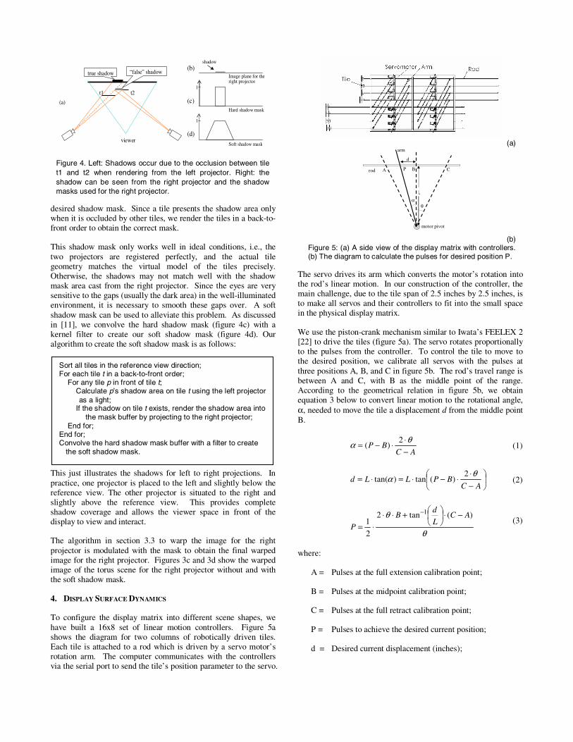
desired shadow mask. Since a tile presents the shadow area only when it is occluded by other tiles, we render the tiles in a back-to-front order to obtain the correct mask.
This shadow mask only works well in ideal conditions, i.e., the two projectors are registered perfectly, and the actual tile geometry matches the virtual model of the tiles precisely. Otherwise, the shadows may not match well with the shadow mask area cast from the right projector. Since the eyes are very sensitive to the gaps (usually the dark area) in the well-illuminated environment, it is necessary to smooth these gaps over. A soft shadow mask can be used to alleviate this problem. As discussed in [11], we convolve the hard shadow mask (figure 4c) with a kernel filter to create our soft shadow mask (figure 4d). Our algorithm to create the soft shadow mask is as follows:
This just illustrates the shadows for left to right projections. In practice, one projector is placed to the left and slightly below the reference view. The other projector is situated to the right and slightly above the reference view. This provides complete shadow coverage and allows the viewer space in front of the display to view and interact.
The algorithm in section 3.3 to warp the image for the right projector is modulated with the mask to obtain the final warped image for the right projector. Figures 3c and 3d show the warped image of the torus scene for the right projector without and with the soft shadow mask.
4. DISPLAY SURFACE DYNAMICS
To configure the display matrix into different scene shapes, we have built a 16x8 set of linear motion controllers. Figure 5a shows the diagram for two columns of robotically driven tiles. Each tile is attached to a rod which is driven by a servo motor’s rotation arm. The computer communicates with the controllers via the serial port to send the tile’s position parameter to the servo.
The servo drives its arm which converts the motor’s rotation into the rod’s linear motion. In our construction of the controller, the main challenge, due to the tile span of 2.5 inches by 2.5 inches, is to make all servos and their controllers to fit into the small space in the physical display matrix.
We use the piston-crank mechanism similar to Iwata’s FEELEX 2 [22] to drive the tiles (figure 5a). The servo rotates proportionally to the pulses from the controller. To control the tile to move to the desired position, we calibrate all servos with the pulses at three positions A, B, and C in figure 5b. The rod’s travel range is between A and C, with B as the middle point of the range. According to the geometrical relation in figure 5b, we obtain equation 3 below to convert linear motion to the rotational angle, α, needed to move the tile a displacement d from the middle point B.
ACBP
−⋅⋅−= θα 2
)( (1)
⎟⎠
⎞⎜⎝
⎛−⋅
⋅−⋅=⋅=AC
BPLLdθα 2
)(tan)tan( (2)
θ
θ )(tan2
2
11 AC
L
dB
P
−⋅⎟⎠⎞
⎜⎝⎛+⋅⋅
⋅=
−
(3)
where:
A = Pulses at the full extension calibration point;
B = Pulses at the midpoint calibration point;
C = Pulses at the full retract calibration point;
P = Pulses to achieve the desired current position;
d = Desired current displacement (inches);
(a)
A B C
θα
P
d
rod
motor pivot
arm
(b)
Figure 5: (a) A side view of the display matrix with controllers. (b) The diagram to calculate the pulses for desired position P.
Sort all tiles in the reference view direction; For each tile t in a back-to-front order;
For any tile p in front of tile t; Calculate p’s shadow area on tile t using the left projector as a light;
If the shadow on tile t exists, render the shadow area into the mask buffer by projecting to the right projector;
End for; End for; Convolve the hard shadow mask buffer with a filter to create
the soft shadow mask.
viewer
“false” shadow true shadow
t1 t2
(a)
Image plane for the right projector
Soft shadow mask
Hard shadow mask
shadow (b)
(c)
(d)
1
1
Figure 4. Left: Shadows occur due to the occlusion between tile t1 and t2 when rendering from the left projector. Right: the shadow can be seen from the right projector and the shadow masks used for the right projector.
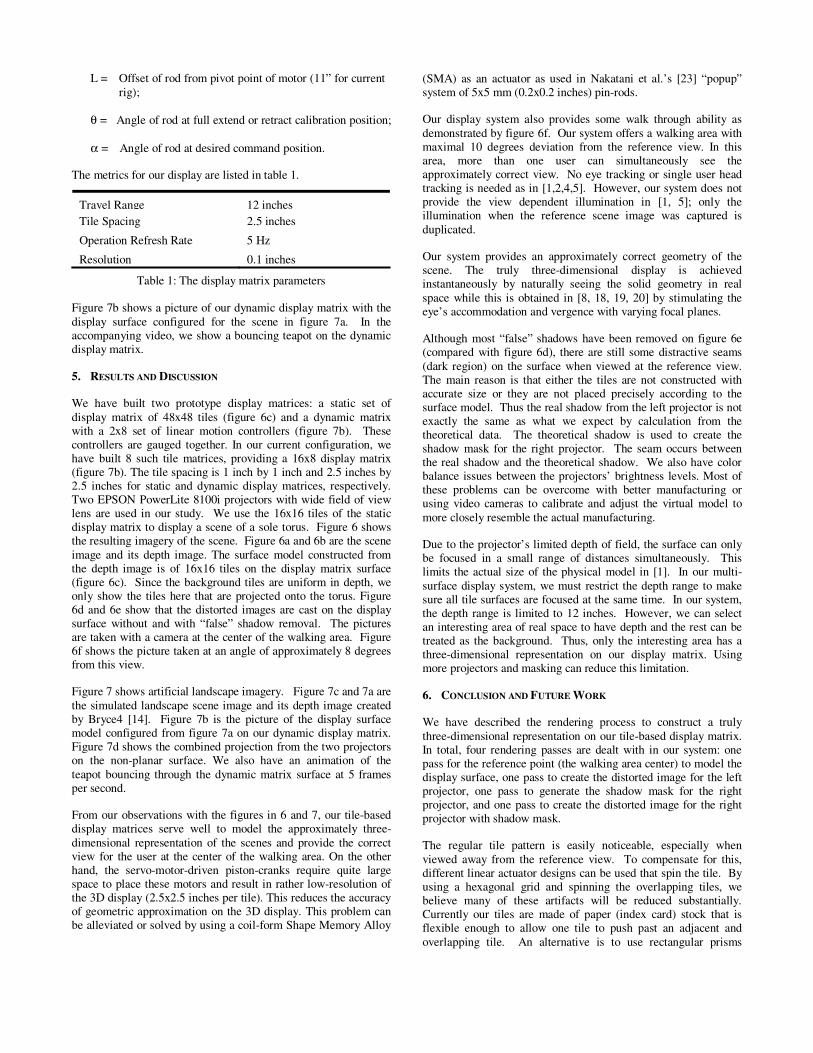
L = Offset of rod from pivot point of motor (11” for current rig);
θ = Angle of rod at full extend or retract calibration position;
α = Angle of rod at desired command position.
The metrics for our display are listed in table 1.
Travel Range 12 inches Tile Spacing 2.5 inches
Operation Refresh Rate 5 Hz
Resolution 0.1 inches
Table 1: The display matrix parameters
Figure 7b shows a picture of our dynamic display matrix with the display surface configured for the scene in figure 7a. In the accompanying video, we show a bouncing teapot on the dynamic display matrix.
5. RESULTS AND DISCUSSION
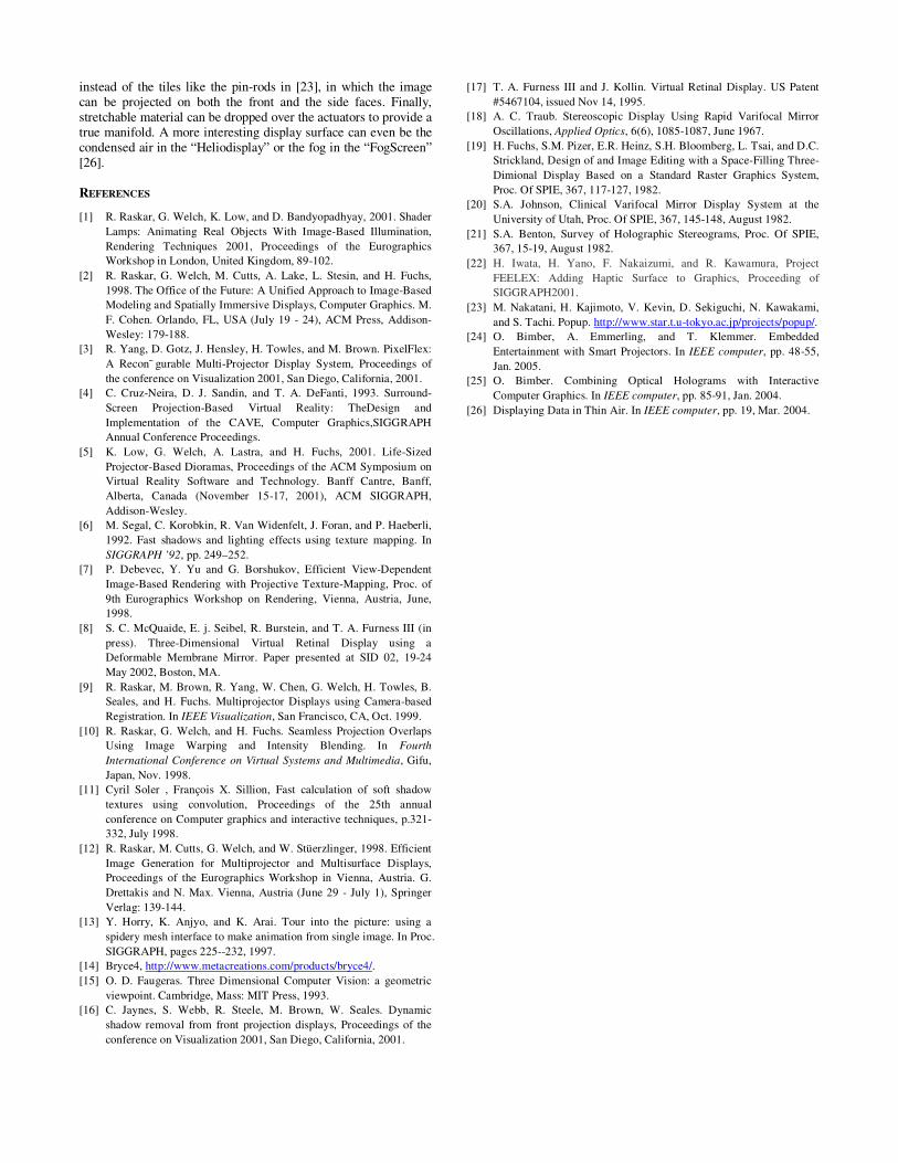
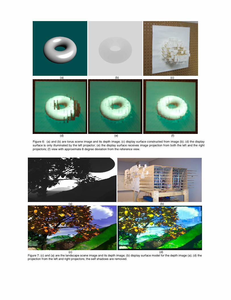
We have built two prototype display matrices: a static set of display matrix of 48x48 tiles (figure 6c) and a dynamic matrix with a 2x8 set of linear motion controllers (figure 7b). These controllers are gauged together. In our current configuration, we have built 8 such tile matrices, providing a 16x8 display matrix (figure 7b). The tile spacing is 1 inch by 1 inch and 2.5 inches by 2.5 inches for static and dynamic display matrices, respectively. Two EPSON PowerLite 8100i projectors with wide field of view lens are used in our study. We use the 16x16 tiles of the static display matrix to display a scene of a sole torus. Figure 6 shows the resulting imagery of the scene. Figure 6a and 6b are the scene image and its depth image. The surface model constructed from the depth image is of 16x16 tiles on the display matrix surface (figure 6c). Since the background tiles are uniform in depth, we only show the tiles here that are projected onto the torus. Figure 6d and 6e show that the distorted images are cast on the display surface without and with “false” shadow removal. The pictures are taken with a camera at the center of the walking area. Figure 6f shows the picture taken at an angle of approximately 8 degrees from this view.
Figure 7 shows artificial landscape imagery. Figure 7c and 7a are the simulated landscape scene image and its depth image created by Bryce4 [14]. Figure 7b is the picture of the display surface model configured from figure 7a on our dynamic display matrix. Figure 7d shows the combined projection from the two projectors on the non-planar surface. We also have an animation of the teapot bouncing through the dynamic matrix surface at 5 frames per second.
From our observations with the figures in 6 and 7, our tile-based display matrices serve well to model the approximately three-dimensional representation of the scenes and provide the correct view for the user at the center of the walking area. On the other hand, the servo-motor-driven piston-cranks require quite large space to place these motors and result in rather low-resolution of the 3D display (2.5x2.5 inches per tile). This reduces the accuracy of geometric approximation on the 3D display. This problem can be alleviated or solved by using a coil-form Shape Memory Alloy
(SMA) as an actuator as used in Nakatani et al.’s [23] “popup” system of 5x5 mm (0.2x0.2 inches) pin-rods.
Our display system also provides some walk through ability as demonstrated by figure 6f. Our system offers a walking area with maximal 10 degrees deviation from the reference view. In this area, more than one user can simultaneously see the approximately correct view. No eye tracking or single user head tracking is needed as in [1,2,4,5]. However, our system does not provide the view dependent illumination in [1, 5]; only the illumination when the reference scene image was captured is duplicated.
Our system provides an approximately correct geometry of the scene. The truly three-dimensional display is achieved instantaneously by naturally seeing the solid geometry in real space while this is obtained in [8, 18, 19, 20] by stimulating the eye’s accommodation and vergence with varying focal planes.
Although most “false” shadows have been removed on figure 6e (compared with figure 6d), there are still some distractive seams (dark region) on the surface when viewed at the reference view. The main reason is that either the tiles are not constructed with accurate size or they are not placed precisely according to the surface model. Thus the real shadow from the left projector is not exactly the same as what we expect by calculation from the theoretical data. The theoretical shadow is used to create the shadow mask for the right projector. The seam occurs between the real shadow and the theoretical shadow. We also have color balance issues between the projectors’ brightness levels. Most of these problems can be overcome with better manufacturing or using video cameras to calibrate and adjust the virtual model to more closely resemble the actual manufacturing.
Due to the projector’s limited depth of field, the surface can only be focused in a small range of distances simultaneously. This limits the actual size of the physical model in [1]. In our multi-surface display system, we must restrict the depth range to make sure all tile surfaces are focused at the same time. In our system, the depth range is limited to 12 inches. However, we can select an interesting area of real space to have depth and the rest can be treated as the background. Thus, only the interesting area has a three-dimensional representation on our display matrix. Using more projectors and masking can reduce this limitation.
6. CONCLUSION AND FUTURE WORK
We have described the rendering process to construct a truly three-dimensional representation on our tile-based display matrix. In total, four rendering passes are dealt with in our system: one pass for the reference point (the walking area center) to model the display surface, one pass to create the distorted image for the left projector, one pass to generate the shadow mask for the right projector, and one pass to create the distorted image for the right projector with shadow mask.
The regular tile pattern is easily noticeable, especially when viewed away from the reference view. To compensate for this, different linear actuator designs can be used that spin the tile. By using a hexagonal grid and spinning the overlapping tiles, we believe many of these artifacts will be reduced substantially. Currently our tiles are made of paper (index card) stock that is flexible enough to allow one tile to push past an adjacent and overlapping tile. An alternative is to use rectangular prisms
instead of the tiles like the pin-rods in [23], in which the image can be projected on both the front and the side faces. Finally, stretchable material can be dropped over the actuators to provide a true manifold. A more interesting display surface can even be the condensed air in the “Heliodisplay” or the fog in the “FogScreen” [26].
REFERENCES
[1] R. Raskar, G. Welch, K. Low, and D. Bandyopadhyay, 2001. Shader Lamps: Animating Real Objects With Image-Based Illumination, Rendering Techniques 2001, Proceedings of the Eurographics Workshop in London, United Kingdom, 89-102.
[2] R. Raskar, G. Welch, M. Cutts, A. Lake, L. Stesin, and H. Fuchs, 1998. The Office of the Future: A Unified Approach to Image-Based Modeling and Spatially Immersive Displays, Computer Graphics. M. F. Cohen. Orlando, FL, USA (July 19 - 24), ACM Press, Addison-Wesley: 179-188.
[3] R. Yang, D. Gotz, J. Hensley, H. Towles, and M. Brown. PixelFlex: A Recon¯ gurable Multi-Projector Display System, Proceedings of the conference on Visualization 2001, San Diego, California, 2001.
[4] C. Cruz-Neira, D. J. Sandin, and T. A. DeFanti, 1993. Surround-Screen Projection-Based Virtual Reality: TheDesign and Implementation of the CAVE, Computer Graphics,SIGGRAPH Annual Conference Proceedings.
[5] K. Low, G. Welch, A. Lastra, and H. Fuchs, 2001. Life-Sized Projector-Based Dioramas, Proceedings of the ACM Symposium on Virtual Reality Software and Technology. Banff Cantre, Banff, Alberta, Canada (November 15-17, 2001), ACM SIGGRAPH, Addison-Wesley.
[6] M. Segal, C. Korobkin, R. Van Widenfelt, J. Foran, and P. Haeberli, 1992. Fast shadows and lighting effects using texture mapping. In SIGGRAPH ’92, pp. 249–252.
[7] P. Debevec, Y. Yu and G. Borshukov, Efficient View-Dependent Image-Based Rendering with Projective Texture-Mapping, Proc. of 9th Eurographics Workshop on Rendering, Vienna, Austria, June, 1998.
[8] S. C. McQuaide, E. j. Seibel, R. Burstein, and T. A. Furness III (in press). Three-Dimensional Virtual Retinal Display using a Deformable Membrane Mirror. Paper presented at SID 02, 19-24 May 2002, Boston, MA.
[9] R. Raskar, M. Brown, R. Yang, W. Chen, G. Welch, H. Towles, B. Seales, and H. Fuchs. Multiprojector Displays using Camera-based Registration. In IEEE Visualization, San Francisco, CA, Oct. 1999.
[10] R. Raskar, G. Welch, and H. Fuchs. Seamless Projection Overlaps Using Image Warping and Intensity Blending. In Fourth International Conference on Virtual Systems and Multimedia, Gifu, Japan, Nov. 1998.
[11] Cyril Soler , François X. Sillion, Fast calculation of soft shadow textures using convolution, Proceedings of the 25th annual conference on Computer graphics and interactive techniques, p.321-332, July 1998.
[12] R. Raskar, M. Cutts, G. Welch, and W. Stüerzlinger, 1998. Efficient Image Generation for Multiprojector and Multisurface Displays, Proceedings of the Eurographics Workshop in Vienna, Austria. G. Drettakis and N. Max. Vienna, Austria (June 29 - July 1), Springer Verlag: 139-144.
[13] Y. Horry, K. Anjyo, and K. Arai. Tour into the picture: using a spidery mesh interface to make animation from single image. In Proc. SIGGRAPH, pages 225--232, 1997.
[14] Bryce4, http://www.metacreations.com/products/bryce4/. [15] O. D. Faugeras. Three Dimensional Computer Vision: a geometric
viewpoint. Cambridge, Mass: MIT Press, 1993. [16] C. Jaynes, S. Webb, R. Steele, M. Brown, W. Seales. Dynamic
shadow removal from front projection displays, Proceedings of the conference on Visualization 2001, San Diego, California, 2001.
[17] T. A. Furness III and J. Kollin. Virtual Retinal Display. US Patent #5467104, issued Nov 14, 1995.
[18] A. C. Traub. Stereoscopic Display Using Rapid Varifocal Mirror Oscillations, Applied Optics, 6(6), 1085-1087, June 1967.
[19] H. Fuchs, S.M. Pizer, E.R. Heinz, S.H. Bloomberg, L. Tsai, and D.C. Strickland, Design of and Image Editing with a Space-Filling Three-Dimional Display Based on a Standard Raster Graphics System, Proc. Of SPIE, 367, 117-127, 1982.
[20] S.A. Johnson, Clinical Varifocal Mirror Display System at the University of Utah, Proc. Of SPIE, 367, 145-148, August 1982.
[21] S.A. Benton, Survey of Holographic Stereograms, Proc. Of SPIE, 367, 15-19, August 1982.
[22] H. Iwata, H. Yano, F. Nakaizumi, and R. Kawamura, Project FEELEX: Adding Haptic Surface to Graphics, Proceeding of SIGGRAPH2001.
[23] M. Nakatani, H. Kajimoto, V. Kevin, D. Sekiguchi, N. Kawakami, and S. Tachi. Popup. http://www.star.t.u-tokyo.ac.jp/projects/popup/.
[24] O. Bimber, A. Emmerling, and T. Klemmer. Embedded Entertainment with Smart Projectors. In IEEE computer, pp. 48-55, Jan. 2005.
[25] O. Bimber. Combining Optical Holograms with Interactive Computer Graphics. In IEEE computer, pp. 85-91, Jan. 2004.
[26] Displaying Data in Thin Air. In IEEE computer, pp. 19, Mar. 2004.
(a) (b) (c)
(d) (e) (f)
Figure 6: (a) and (b) are torus scene image and its depth image; (c) display surface constructed from image (b); (d) the display surface is only illuminated by the left projector; (e) the display surface receives image projection from both the left and the right projectors; (f) view with approximate 8 degree deviation from the reference view.
(a) (b)
(c) (d) Figure 7: (c) and (a) are the landscape scene image and its depth image; (b) display surface model for the depth image (a); (d) the projection from the left and right projectors; the self shadows are removed.