Embed Size (px)
Citation preview

IEEE TRANSACTIONS ON VERY LARGE SCALE INTEGRATION (VLSI) SYSTEMS, VOL. 10, NO. 4, AUGUST 2002 399
HW/SW Codesign Techniques for DynamicallyReconfigurable Architectures
Juanjo Noguera and Rosa M. Badia
Abstract—Hardward/software (HW/SW) codesign and recon-figurable computing are commonly used methodologies for digital-systems design. However, no previous work has been carried outin order to define a HW/SW codesign methodology with dynamicscheduling for run-time reconfigurable architectures. In addition,all previous approaches to reconfigurable computing multicontextscheduling are based on static-scheduling techniques. In this paper,we present three main contributions: 1) a novel HW/SW codesignmethodology with dynamic scheduling for discrete event systemsusing dynamically reconfigurable architectures; 2) a new dynamicapproach to reconfigurable computing multicontext scheduling;and 3) a HW/SW partitioning algorithm for dynamically reconfig-urable architectures. We have developed a whole codesign frame-work, where we have applied our methodology and algorithms tothe case study of software acceleration. An exhaustive study hasbeen carried out, and the obtained results demonstrate the bene-fits of our approach.
Index Terms—Dynamic scheduling, dynamically reconfigurablearchitectures, HW/SW codesign, HW/SW partitioning.
I. INTRODUCTION
THE CONTINUED progress of semiconductor technologyhas enabled the “system-on-chip” (SoC) to become a
reality. In this sense, programmable logic manufacturers havealso proposed new products. An example of this is the Altera’snew device Excalibur, which integrates a processor core (ARM,MIPS, or NIOS), embedded memory and programmable logic[1]. New types of devices, which are run-time reconfigurable,have also been proposed thanks to the advents of the dynam-ically reconfigurable logic (DRL). An example of this, is theVirtex family from Xilinx, which is partially reconfigurable atrun time [2]. A hybrid device, which combines both above ex-plained features, is the CS2112 chip from Chameleon Systems,Inc. This device integrates a RISC core, embedded memory, anda run-time reconfigurable fabric on a single chip [3]. Clearly,all these devices could be used as the final-target architectureof a hardware/software (HW/SW) codesign methodology.Reconfigurable computing (RC) [16] is an interesting
alternative to application specific integrated circuits (ASICs)and the general-purpose processor systems, since it providesthe flexibility of software processors and the efficiency and
Manuscript received October 30, 2000; revised January 18, 2002. This workwas supported by CICYT-TIC project TIC2001-2476-C03-02.J. Noguera is with Hewlett-Packard Inkjet Commercial Division, Department
of Research and Development, San Cugat del Valles, 08190 Spain (e-mail:[email protected]).R. M. Badia is with the Technical University of Catalonia (DAC-UPC),
Computer Architecture Department, Barcelona, 08034 Spain (e-mail:[email protected]).Digital Object Identifier 10.1109/TVLSI.2002.801575
throughput of hardware coprocessors. DRL devices and ar-chitectures present new and exciting challenges to the designautomation community. The major challenge introduced byDRL devices is the reconfiguration latency, which must beminimized in order to maximize application performance.In order to achieve run-time reconfiguration, the systemspecification (typically, a task graph) must be partitioned intotemporal exclusive segments (called reconfiguration contexts).This process is usually known as temporal partitioning andit is a way to address the problem of reconfiguration latency.A different approach is to find an execution order for a set oftasks that meets system-design objectives (i.e., minimize theapplication execution time). This is known as DRL multicontextscheduling.There are a great number of approaches to HW/SW code-
sign of embedded systems, which use different techniques forpartitioning and scheduling. However, DRL devices and archi-tectures change many of the basic assumptions in the HW/SWcodesign process. The flexibility of dynamic reconfiguration(multiple configurations, partial and run-time reconfiguration,etc.) requires new methodologies and the development of newalgorithms, as conventional codesign approaches do not con-sider the features of these new DRL devices and architectures.
A. Previous Related WorkTraditionally, HW/SW codesign challenges and DRL chal-
lenges have been addressed independently.Earlier approaches to the HW/SW codesign, model the
system based on a template of a CPU and an ASIC [11],[14]. HW/SW partitioning and scheduling techniques can bedifferentiated in several ways. For instance, partitioning can beclassified as fine-grained (if it partitions the system specifica-tion at the basic-block level) or as coarse-grained (if systemspecification is partitioned at the process or task level). Also,HW/SW scheduling can be classified as static or dynamic. Ascheduling policy is said to be static when tasks are executedin a fixed order determined offline, and dynamic when theorder of execution is decided online. HW/SW tasks’ sequencecan change dynamically in complex embedded systems (i.e.,control-dominated applications), since such systems often haveto operate under many different conditions. Although, therehas been a lot of previous work in static HW/SW scheduling,the dynamic scheduling problem in HW/SW codesign hasonly been addressed in a few research efforts. A strategy forthe mixed implementation of dynamic real-time schedulersin HW/SW is presented in [27]. In [4] a review of severalapproaches to control-dominated and dataflow-dominatedsoftware scheduling is presented.
1063-8210/02$17.00 © 2002 IEEE
Authorized licensed use limited to: University of Florida. Downloaded on March 17, 2009 at 18:35 from IEEE Xplore. Restrictions apply.

400 IEEE TRANSACTIONS ON VERY LARGE SCALE INTEGRATION (VLSI) SYSTEMS, VOL. 10, NO. 4, AUGUST 2002
On the other hand, several approaches can be found in theliterature addressing reconfiguration latency minimization.Configuration prefetching techniques have been used forreconfiguration latency minimization. They are based on theidea of loading the next reconfiguration context before itis required, hence, overlapping device reconfiguration andapplication execution. Hauck first introduced configurationprefetching in [15], where a single-context prefetching tech-nique is presented. Also, several references can be found inthe literature addressing temporal partitioning and multicontextscheduling for reconfiguration latency minimization. See [24]as an example. All these previous approaches address theproblem of reconfiguration latency minimization, but they donot address HW/SW partitioning and scheduling.Recent research efforts have addressed this open problem.
In [7], an integrated algorithm for HW/SW partitioning andscheduling, temporal partitioning, and context scheduling ispresented. A more recent work [22] presents a fine-grainedHW/SW partitioning algorithm (at loop level). Both previousapproaches are similar to [12] which take the reconfigurationtime into account when performing the partitioning, but they donot consider the effects of configuration prefetching for latencyminimization. In [17], this topic is introduced, and a HW/SWcosynthesis approach for partially reconfigurable devices ispresented. They do not address multicontext devices. Moreover,this approach, which is based on an ILP formulation, is limitedby the high execution times of the algorithm, which hardlygives solutions for task graphs having more than ten tasks.
B. Motivation and Contributions of the Paper
New approaches are possible because 1) all existing ap-proaches to DRL multicontext scheduling are based on static(compile time) scheduling techniques and 2) no previouswork has been carried out in order to define a HW/SW code-sign methodology with dynamic scheduling based on DRLarchitectures.In this paper, we address these two open problems and
present the following: 1) a novel HW/SW codesign method-ology with dynamic scheduling for dynamically reconfigurablearchitectures, 2) a dynamic approach to DRL multicontextscheduling, and 3) an automatic HW/SW partitioning algorithmfor DRL architectures. The proposed algorithm takes into ac-count the reconfiguration latency when performing the HW/SWpartitioning. The experiments carried out demonstrate that thebenefits of using a prefetching technique, for reconfigurationlatency minimization, can be improved if it is considered at theHW/SW partitioning level.The rest of the paper is organized as follows: Section II
introduces the HW/SW codesign methodology with dynamicscheduling, and the target architectures (named, local, andshared memory architectures). In Sections III and IV, wepresent two-different algorithms (HW/SW partitioning andDRL multicontext scheduling) for the shared and local memoryarchitectures. In Section V, we apply our methodology andalgorithms to the software acceleration of telecom networkssimulation, and present the obtained results. An improvedHW/SW partitioning algorithm for DRL architectures is
presented in Section VI. Finally, Section VII presents theconclusions of this work.
II. HW/SW CODESIGN FOR DISCRETE EVENT SYSTEMS
Discrete event (DE) systems design has been recently ad-dressed using HW/SW codesign techniques [13], [21]. How-ever, none of these approaches is based on DRL devices as thehardware platform.The methodology presented here addresses the problem of
HW/SW codesign with dynamic scheduling for DE systemsusing a heterogeneous architecture that contains a standardoff-the-shelf processor and a DRL based architecture. It isimportant to note that the proposed methodology followsan object orientation paradigm, and uses the object orientedconcepts in all its steps (specification, HW/SW partitioning andscheduling, etc.). The majority of previous related work onlyuses this object oriented approach at the system specification(modeling) level. See [37], as an example.
A. Definitions
1) Discrete event class is a concurrent process type with acertain behavior, which is specified as a function of thestate variables and input events. See Fig. 1(a).
2) Discrete event object is a concrete instance of a DE class.Several DE objects from a single DE class are possible.Given twoDE objects ( and ) theymay differin the value of their state variables. See Fig. 1(b).
3) Event is a member of where is a setof tags, (the real numbers), a given set of DEclasses, a set of DE objects, and a set of values. Tagsare used to model time and values represent operands orresults of event computation.
4) Event stream (ES) is a list of events sequentially orderedby tag. Tags can represent, for example, event occurrenceor event deadline. See Fig. 1(c).
5) Discrete event functional unit is a physical component(i.e., DRL device or SW processor) where an event
can be executed. A functional unit has anactive pair (class, object), . See Fig. 1(d).Our methodology assumes that: (1) several DE classes
could be mapped into a single DE functional unit, and (2)all DE objects from a DE class are mapped into the sameDE functional unit where the DE class has been mapped.
6) Object switch is the mechanism that allows a DE func-tional unit to change from one DE object to another, bothDE objects belonging to a same DE class. For example,if an input event has to be processedin a DE functional unit with an active pairthen an object switch should be performed. Object switchmeans a change of values in the state variables from theones of a concrete DE object to the others of anotherDE object .
7) Class switch is themechanism that allows aDE functionalunit to change from one DE class to another. For example,if an input event should be processedin a DE functional unit with an active pair ,
Authorized licensed use limited to: University of Florida. Downloaded on March 17, 2009 at 18:35 from IEEE Xplore. Restrictions apply.
NOGUERA AND BADIA: HW/SW CODESIGN TECHNIQUES 401
(a) (b) (c) (d)
Fig. 1. HW/SW codesign methodology definitions.
Fig. 2. HW/SW codesign methodology.
then a class switch should be performed. Class switch, incase of a DRL device, means a context reconfiguration.
B. HW/SW Codesign Methodology With Dynamic Scheduling
The methodology we propose is depicted in Fig. 2. It is di-vided in three stages: application stage, static stage, and dy-namic stage. The key points in our methodology are: (1) appli-cation and dynamic stages handle DE classes and objects, and(2) static stage only handles DE classes.The application stage includes discrete event system speci-
fication and design constraints. We assume the use of an ho-mogenous modeling language for system specification, wherea set of independent DE classes must be first modeled. After-wards, these DE classes are used to specify the entire system as aset of interrelated DE objects, which communicate among themusing events. These DE objects are interrelated creating a con-crete topology. A DE object computation is activated upon thearrival of an event. By design constraints we understand any de-sign requirement necessary when synthesizing the design (i.e.,timing or area requirements).The static stage includes typical phases of a codesignmethod-
ology: (1) estimation, (2) HW/SW partitioning, (3) HW and SWsynthesis, and (4) extraction.As previously stated, the static stage handles DE classes.
However, the system has been specified as a set of interrelatedDE objects, which are instances of previously specified DEclasses. The final goals of the methodology’s extraction phase
are, for a given DE class, to obtain 1) a list of all its instances(DE objects) and 2) a list of all different DE classes and objectsconnected to it. Both lists are afterwards attached to each DEclass found in the system specification. Once this step hasfinished, DE classes can be viewed as a set of independenttasks.Note that although our methodology, addresses DRL archi-
tectures, a temporal partitioning phase can not be found. TheDE object/class extraction phase should be viewed as the tem-poral partitioning algorithm. Indeed, the temporal partitioningalgorithm is included within our concept of DE class, as DEclasses are functionally independent tasks.We classify our HW/SW partitioning approach as coarse-
grained, since it works at the DE class level. Different HW/SWpartitioning algorithms can be applied depending on the appli-cation. The solution obtained by the HW/SW partitioning algo-rithm should meet design constraints.The estimation phase also deals with DE classes and the used
estimators depend on the final application. Typically used es-timators (HW/SW execution time, DRL area, etc.) can be ob-tained using high-level synthesis and profiling tools.The dynamic stage includes HW/SW Scheduling and DRL
multicontext Scheduling. Both schedulers base their function-ality on the events present in the event stream. Our methodologyassumes that both of them are implemented in hardware usinga centralized control scheme. As it is shown in Fig. 2, thesescheduling policies (HW/SW and DRL) cooperate and runin parallel during application run-time execution, in order to
Authorized licensed use limited to: University of Florida. Downloaded on March 17, 2009 at 18:35 from IEEE Xplore. Restrictions apply.

402 IEEE TRANSACTIONS ON VERY LARGE SCALE INTEGRATION (VLSI) SYSTEMS, VOL. 10, NO. 4, AUGUST 2002
(a)
(b)
Fig. 3. DRL target architectures.
meet design constraints. With this goal, application executiontime is minimized by parallelizing event executions with DRLreconfigurations.The aim of the HW/SW scheduler is to decide at run time the
execution order of the events stored in the event stream. Severalpolicies could be implemented by the HW/SW scheduler basedon the application requirements (i.e., earliest deadline first, useor not of a pre-emptive technique).On the other hand, the DRLmulticontext scheduler should be
viewed as a tool used by the HW/SW scheduler. A tool in the
sense that its goal is to facilitate or minimize the class switchingmechanism to the HW/SW scheduler. As in the HW/SW parti-tioning and scheduling, we assume that different DRL sched-ulers can be defined depending on the application.
C. Target Architectures
The methodology we propose can be mapped to a target ar-chitecture with two variants: the shared memory architecture orthe local memory architecture.
Authorized licensed use limited to: University of Florida. Downloaded on March 17, 2009 at 18:35 from IEEE Xplore. Restrictions apply.

NOGUERA AND BADIA: HW/SW CODESIGN TECHNIQUES 403
1) SharedMemory Target Architecture: The sharedmemorytarget architecture is depicted in Fig. 3(a). This architecture in-cludes a software processor, a DRL-based hardware coprocessorand shared memory resources.The software processor is a uniprocessing system, which can
only execute one event at the same time. The DRL-based copro-cessor can execute multiple events concurrently. HW/SW coop-erate (interact) via a DMA based memory-sharing mechanism.The DRL-based coprocessor architecture is divided in:
1) HW/SW and DRL multicontext scheduler; 2) DRL array;3) object state memory; 4) DRL context memory; and (5)event-stream memory. The HW/SW and DRL multicontextschedulers must implement functions associated to the dynamicstage of our methodology, as previously explained. Eventsget the central scheduler through I/O ports or as a result ofa previous event computation. The event stream is stored inthe event stream memory. DRL contexts (which correspondto several DE classes from an application) are stored in theDRL context memory, and they can be loaded to any DRL cellusing the class bus. Finally, DE objects states (state variables)are stored in the object state memory. Any DRL cell using theobject bus can access the object state variables. The proposedDRL coprocessor architecture is scalable and it is possible toapply any associative mapping between DE objects/classes andDRL cells.The DRL array communicates with these memories and the
central scheduler through several and functionally independentbusses (object, class, and event busses). We assume that eachDRL array element, named DRL cell, can implement any DEclass with a required area 20 K gates.2) Local Memory Target Architecture: Another possibility
for the target architecture is to assume that the object statememory is distributed or local to each DRL cell, all the restremaining as described in the Section I-C1 [see Fig. 3(b)].As previously stated, with a shared object state memory, anyassociative mapping between DE objects/classes and DRL cellscan be implemented. Instead, if a local object state memory isconsidered, the mapping between DE classes/objects and DRLcells should be direct, as the state variables for each objectwould be local to a concrete DRL cell. Both target architec-tures influence the development of the HW/SW partitioningalgorithm and the scheduling algorithms (HW/SW and DRLmulticontext).
III. ALGORITHMS FOR THE SHARED MEMORYTARGET ARCHITECTURE
In this section, we present two algorithms for the sharedmemory architecture: 1) a resource constrained HW/SWpartitioning algorithm and (2) a dynamic DRL multicontextscheduling algorithm.
A. HW/SW Partitioning Algorithm
1) Problem Statement: A set of independent DE classesis the input to the HW/SW partitioning
algorithm, which throughout its execution will work with twosubsets ( and ).
Fig. 4. List-based HW/SW partitioning algorithm for the shared memoryarchitecture.
• is the subset of DE classes mapped to hardware,, .
• is the subset of DE classes mapped to software,, .
• , .A concrete class of the input set of classes, is character-
ized by a set of estimators
AET AET SVM DRLA NO (1)
whereAET average execution time for a hardware imple-
mentation of the class ;AET average execution time for a software implemen-
tation of the class ;SVM state variables memory size required by the
class;DRLA DRL required area for the class;NO number of objects of this class.Let us also consider that design constraints are: (1) object
state memory, (2) class (DRL context) memory, and (3) the DRLcell area. The total object state memory is denoted by OSMA(object state memory available). DRLA stands for the DRL cellavailable Area.We state our problem as maximizing the number of DE
classes mapped to the DRL architecture while meeting memoryresources and DRL cell available area constraints
(2)
2) HW/SW Partitioning Algorithm: The proposed HW/SWalgorithm is a list-based partitioning algorithm. The algorithmmaps more time consuming DE classes to hardware. Thus, theset of input DE classes must be sequentially ordered and moretime consuming DE classes should be prioritized whenmappingto hardware. This objective is implemented using a cost func-tion. For this example, we propose the following cost function,although other cost functions could be applied
(3)
Authorized licensed use limited to: University of Florida. Downloaded on March 17, 2009 at 18:35 from IEEE Xplore. Restrictions apply.

404 IEEE TRANSACTIONS ON VERY LARGE SCALE INTEGRATION (VLSI) SYSTEMS, VOL. 10, NO. 4, AUGUST 2002
(a) (b)
Fig. 5. DRL cell and CPU possible states.
Indeed, this cost function prioritized DE classes with signifi-cant difference in its HW and SW execution times. We assumethat lower values, as a result of applying this cost function, arebetter than higher values. So, our sort function classifies valuesfrom lowest to highest.The pseudocode of the proposed HW/SW partitioning algo-
rithm is shown in Fig. 4. It obtains the initial sequentially or-dered list after the cost function has been applied toall DE classes. Afterwards, the algorithm performs a loop andtries to map as many DE classes to hardware as possible, whilememory and DRL area constraints are met.Available Resources (DeClass ) function checks that the
current hardware partition plus DE class complies withmemory constraints. Function GetFirst (List ) returnsand extracts the first DE class from the initial ordered list.
B. Dynamic DRL Architecture ManagementIn this section, we present the dynamic architecture manage-
ment, and concretely, a dynamic event-drivenDRLmulticontextscheduler for the shared memory target architecture.We assumethat only the first event of the event stream, which is sorted bythe shortest tag, is being processed on aDE functional unit (DRLcell or CPU) at the same time. That is, the HW/SW scheduleronly schedules one event at the same time, which indeed is itsmain objective. Modifications of this scheduler are possible inorder to have several events being processed in parallel.A second objective of the HW/SW scheduler is to manage the
active objects and classes of the DRL cells and CPU, performingthe class and object switches required to execute an event. Thisfunctionality can be observed in Fig. 5, which represents thefinite state machines for the DRL cells, and the CPU. As intro-duced in Section II-B, the HW/SW scheduler is implementedusing a centralized control scheme, whichmeans that this sched-uler controls all DRL cells and CPU state transitions, as shownin Fig. 5.Let us explain Fig. 5(a). We can observe that initially a DRL
cell is in the idle state, which represents that the DRL has fin-ishedwith the execution of an event, and it is available to processa new event [see edge H, Fig. 5(a)]. Then, the HW/SW sched-uler selects (following the previous commented policy) an eventto execute in this available DRL cell. To schedule an event canmean to perform different tasks: 1) to enter into the class switchstate, if the event class is not loaded into the DRL cell (edge B);2) to enter into the object switch state, if the event object is notloaded into the DRL cell (edge D); and/or 3) to enter into theexecution state if the DRL cell has already active the required
Fig. 6. HW/SW and DRL dynamic scheduling.
Fig. 7. Dynamic DRL multicontext scheduling.
class and object (edge I). The class switch, object switch, andexecution states are characterized by a processing time, whichis known at compile time. That is, when a DRL cell enters intoone of these three states, the time that the DRL cell will remainin the state is fixed. Whenever, one of these states has finishedits execution, there is a change of the active state. For example,if the active state is class switch, the next active state would be-come object switch (edge C). The same idea is applied to edge E.However, in order to minimize class switching (DRL recon-
figuration) overheads to the HW/SW scheduler and improve thetotal application execution time, it is possible to start loading
Authorized licensed use limited to: University of Florida. Downloaded on March 17, 2009 at 18:35 from IEEE Xplore. Restrictions apply.

NOGUERA AND BADIA: HW/SW CODESIGN TECHNIQUES 405
(a) (b) (c)
Fig. 8. DRL multicontext scheduling examples.
the required DE class into the DRL array before it is actuallyrequired by the HW/SW scheduler (edge A). This is the aimof the DRL multicontext scheduler, which will be explainedin Section III-B1. This scheduling policy is based on a look-ahead strategy into the event stream memory (see Fig. 6). Eventwindow (EW) describes the number of events that are observedin advance and is left as a parameter of our scheduler.By introducing this class switch (reconfiguration) prefetching
mechanism, it is possible to overlap the reconfiguration of aDRL cell with the event execution in another DRL cell. Usingthis approach, it is possible that a given DRL cell finishes withclass and object switch, but the event can not be processed be-cause the execution of the previous events in the event stream(with shortest tags) has not finished. In this case, the DRL cellenters into the waiting state (edge F). Finally, the DRL cell willexit this state and enter into the execution state (edge G), whenordered by the HW/SW scheduler. The time that a DRL cellwill remain in the waiting state is not fixed, and it will be de-termined at run time, according to the dynamic behavior of theevent stream.Following, Fig. 5(b) is explained. This figure depicts the fi-
nite state machine for the CPU. As in the previous case, initiallythe CPU is in the idle state. Whenever, a concrete event must beprocessed by the CPU, the HW/SW scheduler will start a com-munication process with the CPUusing the system bus (edgeA).Indeed, this communication state means to send to the CPU, theevent to be processed. The CPU will perform a class switch if itis required. If an object switch is required, the CPU will enter inthis state (edge C), and if not it will enter in the execution state(edge B). Moreover, and with the idea of minimizing commu-nications overheads, it is possible to start the CPU communica-tion process, while an event is being executed in the DRL array.So, the HW/SW scheduler will start the communication processusing the event window concept. In the same manner as in thecase of a DRL cell, the CPU has a waiting state.1) DRL Multicontext Scheduling Algorithm: The aim of the
DRL multicontext scheduler is to minimize class switching(DRL reconfiguration) overheads to the HW/SW scheduler, inorder to minimize the application execution time. From the DEclasses that are loaded in the DRL array, and the DE classeswhich will be required within the event window (EW), theDRL scheduler must decide, 1) which DE class must be loadedand (2) in which DRL cell it will be loaded.The pseudocode for the dynamic DRL multicontext sched-
uling algorithm is shown in Fig. 7. As stated, this scheduler de-pends on the size of the event window. This algorithm is exe-
cuted at the end of the processing of a concrete event, but con-currently with the execution of the next event. That is, whenan event finishes its execution, a new event will start to be pro-cessed. As a consequence, the event window will be moved tothe next position, and it is probable that new classes are needed.The basis of the behavior of the proposed DRL multicontext
scheduling algorithm is the use of the array DRLArrayUtiliza-tion, which represents the expected active DE classes and asso-ciated tags of the DRL array within the event window. This arrayis obtained from the current state of the DRL array and the eventwindow, using the function ObtainDRLArrayUtilization.Afterwards, the algorithm calculates the number of DRL cells
that will not be required within the event window (variable ).These DRL cells (if there is any) are available for a class(context) switch. So, this is the first condition that the algorithmchecks.If there is not any DRL cell available for a class switch, the
algorithm selects (to reconfigure) the DRL cell that has an activeDE class that will be required latest. Note that this is not a typicallast recently used (LRU) replacement policy. The algorithm alsoselects a DE class to be loaded. The first DE class found in theevent stream, which is not loaded within the DRL array willbe selected. Finally, it will check that the event tag (associatedwith the first class not present in the DRL array) is lower thanthe DRL tag (the tag at which the loaded class into the DRL cellwill be required). We assume that all tags are different, althoughthis difference could be small. If this condition is asserted, thealgorithm sets the DRL cell into the class switch state using thefunction DRL_Behavior( ).On the other hand, if there are DRL cells available for a
class switch, the algorithm enters into a loop that goes throughthe entire event window (beginning from the current event,CE).If it finds a class (associated with an event), which is not loadedwithin the DRL array, the algorithm selects the first availableDRL cell to reconfigure.Fig. 8 shows three different possible cases for the DRL mul-
ticontext scheduler, and how does it work. In these examples,it is depicted: (1) the event stream (with associated classes andtags) and the current processed event, which is shadowed, (2)the DRL array, and for each DRL cell, the current loaded class;the shadowed DRL cell means that it is executing the currentevent, and (3) the array used by the DRL multicontext sched-uler, DRLArrayUtilization.In Fig. 8(a), it is possible to observe that all loaded classes
will be required within the event window. Thus, the DRLAr-rayUtilization shows, for each DRL cell, at which tag it will
Authorized licensed use limited to: University of Florida. Downloaded on March 17, 2009 at 18:35 from IEEE Xplore. Restrictions apply.

406 IEEE TRANSACTIONS ON VERY LARGE SCALE INTEGRATION (VLSI) SYSTEMS, VOL. 10, NO. 4, AUGUST 2002
Fig. 9. List-based HW/SW partitioning algorithm for the local memory architecture.
be required. For example, it is observed that has loadedDE class 2, and the position of the DRLArrayUtilization asso-ciated to has a value of 5, which means that withactive DE class 2, will be required at tag 5. Fig. 8(a). representsthe case in which because all loaded classes in the DRLarray are required within the event window. In this case, the al-gorithm will select to reconfigure (it is the one whichwill be required latest, and DE class 5 to be loaded (it is the firstclass in the event stream which is not active). However, no re-configuration will be performed because the tag of event withDE class 5 is greater than the tag at which the will berequired. Fig. 8(b). represents a similar case, in which .The difference between this and the previous case, is that in thiscase, the reconfiguration will be performed because the tag ofevent with DE class 5 is smaller than the tag at which thewill be required. Finally, Fig. 8(c). represents the case in which
and are not required within the event window, so. In this case, several reconfigurations can be performed
and DE classes 5 and 6 will be loaded.
IV. ALGORITHMS FOR THE LOCAL MEMORYTARGET ARCHITECTURE
In this section we present a HW/SW partitioning algorithmand a DRL multicontext scheduling algorithm for the localmemory target architecture.
A. HW/SW Partitioning Algorithm
As we have explained, when the local memory target archi-tecture is assumed, a direct mapping of DE classes to DRL cellshas to be used. This section presents a HW/SW partitioning al-gorithm, which as in the previous considered architecture, is listbased. As in the previous case, more time consuming DE classesare mapped to hardware. Moreover, this algorithm not only de-cides the classes that will be executed in hardware, but also de-
cides in which DRL cell will always be executed the events ofeach class.Fig. 9 shows the proposed algorithm. Initially, it sorts the list
of DE classes using the same sort function as in Sec-tion III. Afterwards, it performs a loop where for each DE classit is decided whether the class is mapped to hardware or soft-ware. If it is mapped to hardware, the class is assigned to aconcrete DRL cell. The algorithm assigns DE classes to DRLcells in a cyclic way, but it should be checked that there isenough memory in the local object state memory to host thenew DE class. This is performed by the function AvailableRe-sources(DEClass ,DRLCell ), which checks that:• There is enough DRL context memory to store the con-texts of the classes of plus .
• There is enough local Object State Memory to store thestate of classes assigned to plus
B. Dynamic DRL multicontext SchedulerIn this section, we present a dynamic event-driven DRL mul-
ticontext scheduler for the local memory target architecture. Thebasic ideas and assumptions explained in the case of the DRLmulticontext scheduler for the shared memory architecture arealso valid in this case. The DRL cell behavior is also the samein this scheduler [see Fig. 5(a)].The only difference between this scheduler and the one pre-
sented for the shared memory architecture, is the mapping be-tween classes/objects and DRL cells. In this case, the mappingis direct and decided (fixed) at compile-time within the HW/SWpartitioning algorithm. So, this DRLmulticontext scheduler hasas input a table that contains, for all DE classes found in thesystem specification, the DRL cell where a concrete DE classhas to be executed.The algorithm sequentially obtains the required classes (from
the events found within the event stream), and for each class itchecks if the destination DRL cell (obtained from the DRL/DEclassmapping table) is available or not to perform a class switch.
Authorized licensed use limited to: University of Florida. Downloaded on March 17, 2009 at 18:35 from IEEE Xplore. Restrictions apply.

NOGUERA AND BADIA: HW/SW CODESIGN TECHNIQUES 407
Fig. 10. SONATA network architecture.
TABLE IDE CLASSES AND DE OBJECTS FOR THE SONATA EXAMPLE
V. A CASE STUDY: TELECOM NETWORKS SIMULATION
It is widely accepted that software acceleration is an impor-tant field which hardware/software codesign can address. Anexample of this can be found in [10]. We explain a case study ofsoftware acceleration of broad-band telecom networks simula-tion, which is a challenging application. Parallel computing [5]and reconfigurable computing techniques [26], [29], [33] can beused for simulation execution time improvement.
A. Introduction and Simulation ModelFor our case study, we have used the SONATA1 network [6].
It is a network based on the switchless network concept, whichuses a combination of wavelength division multiple access(WDMA) and time division multiple access (TDMA) methods(see Fig. 10). Note that the proposed simulation model dependson a parameter . This parameter will be used afterwards inorder to perform several experiments to test and obtain resultsfrom applying our methodology.The key point of this case study is how to apply the proposed
methodology to the simulation of broad-band telecom networks.Specially important, is the mapping between network elements(found in the network model), and DE objects and classes whichare the basic elements used in our methodology. From Fig. 10,1Switchless Optical Network for Advanced Transport Architecture is partially
funded by the European Commission under ACTS program.
as an example, we can affirm that there are network elements,which are instances from certain network element types. For ex-ample, from Fig. 10 it is possible to find seven different networkelement types: , , network control, passive wavelengthrouter, etc. In this sense, these network element types shouldbe viewed as DE classes within the scope of our methodology.In the same way, network elements should be viewed as DE ob-jects. For this case study, we will not consider the wavelengthconverter array network element. In this case study we assumeto have six different network element types (see Table I).
B. Developed Codesign FrameworkIn order to test our proposed methodology and algorithms,
we have implemented a whole codesign framework, which isdepicted in Fig. 11. In the proposed methodology, DRL targetarchitectures, and dynamic multicontext schedulers, there areseveral parameters that do not have a fixed value. For example:1) the number of DRL cells within the target architecture andits reconfiguration time and 2) the size of the event windowused by the DRL multicontext schedulers. Moreover, the sim-ulation model depends on parameter , too. We have devel-oped a codesign framework to study the effects of these pa-rameters in our proposals. We have implemented two differenttools: 1) a HW/SW partitioning tool and 2) a HW/SW cosim-ulation tool. Within both tools we have implemented the algo-rithms described in this paper, but new algorithms can be easily
Authorized licensed use limited to: University of Florida. Downloaded on March 17, 2009 at 18:35 from IEEE Xplore. Restrictions apply.
408 IEEE TRANSACTIONS ON VERY LARGE SCALE INTEGRATION (VLSI) SYSTEMS, VOL. 10, NO. 4, AUGUST 2002
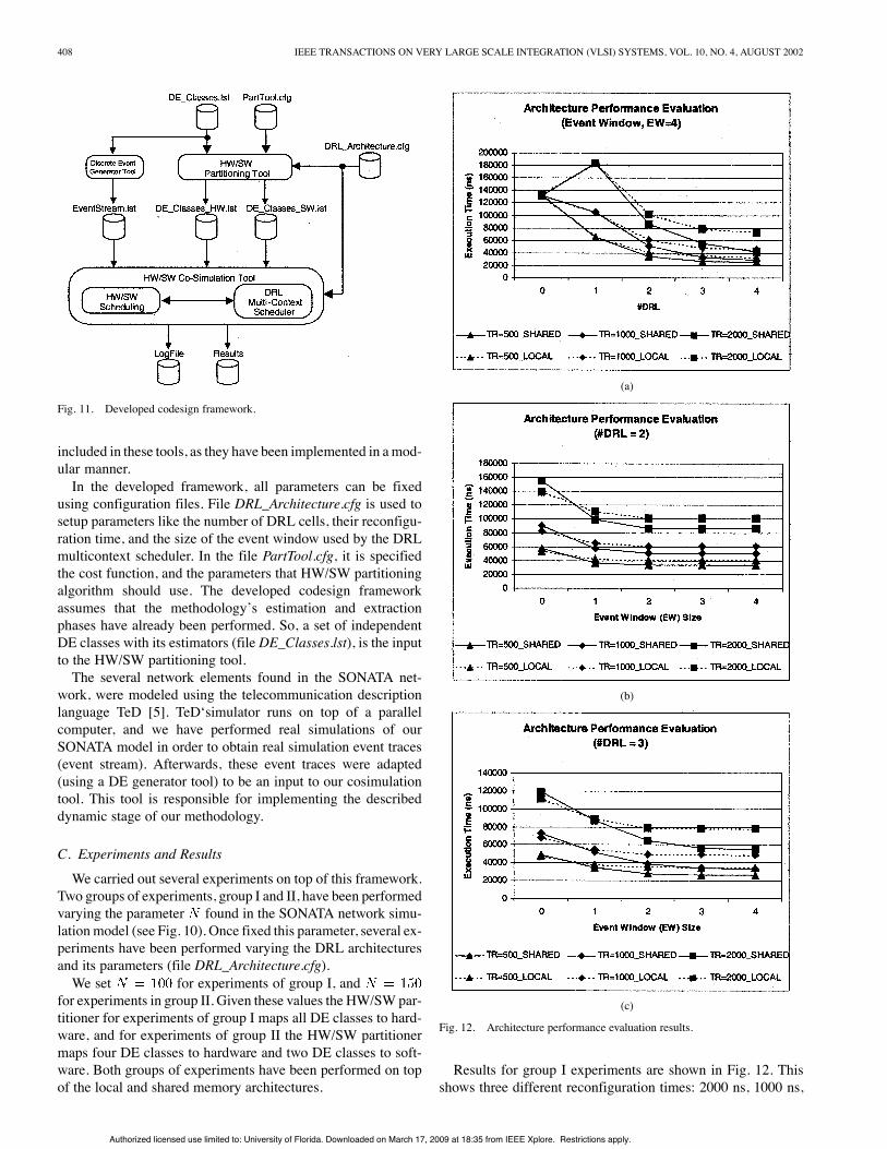
Fig. 11. Developed codesign framework.
included in these tools, as they have been implemented in amod-ular manner.In the developed framework, all parameters can be fixed
using configuration files. File DRL_Architecture.cfg is used tosetup parameters like the number of DRL cells, their reconfigu-ration time, and the size of the event window used by the DRLmulticontext scheduler. In the file PartTool.cfg, it is specifiedthe cost function, and the parameters that HW/SW partitioningalgorithm should use. The developed codesign frameworkassumes that the methodology’s estimation and extractionphases have already been performed. So, a set of independentDE classes with its estimators (file DE_Classes.lst), is the inputto the HW/SW partitioning tool.The several network elements found in the SONATA net-
work, were modeled using the telecommunication descriptionlanguage TeD [5]. TeD‘simulator runs on top of a parallelcomputer, and we have performed real simulations of ourSONATA model in order to obtain real simulation event traces(event stream). Afterwards, these event traces were adapted(using a DE generator tool) to be an input to our cosimulationtool. This tool is responsible for implementing the describeddynamic stage of our methodology.
C. Experiments and Results
We carried out several experiments on top of this framework.Two groups of experiments, group I and II, have been performedvarying the parameter found in the SONATA network simu-lationmodel (see Fig. 10). Once fixed this parameter, several ex-periments have been performed varying the DRL architecturesand its parameters (file DRL_Architecture.cfg).We set for experiments of group I, and
for experiments in group II. Given these values the HW/SW par-titioner for experiments of group I maps all DE classes to hard-ware, and for experiments of group II the HW/SW partitionermaps four DE classes to hardware and two DE classes to soft-ware. Both groups of experiments have been performed on topof the local and shared memory architectures.
(a)
(b)
(c)
Fig. 12. Architecture performance evaluation results.
Results for group I experiments are shown in Fig. 12. Thisshows three different reconfiguration times: 2000 ns, 1000 ns,
Authorized licensed use limited to: University of Florida. Downloaded on March 17, 2009 at 18:35 from IEEE Xplore. Restrictions apply.

NOGUERA AND BADIA: HW/SW CODESIGN TECHNIQUES 409
TABLE IINUMBER OF RECONFIGURATIONS (TOTAL, HW/SW SCHEDULER, DRL MULTICONTEXT SCHEDULER) AND NUMBER OF TIMES THE WAITING IS REACHED
and 500 ns, as we wanted to evaluate the impact of this pa-rameter as well. Fig. 12(a) shows the total network simulationexecution time when the number of DRL cells increases (EWis fixed to four). A value means an all-softwaresimulation execution. From Fig. 12(a), it can be observed thatusing a single DRL cell with a reconfiguration time of 2000 ns,give worst results than an all-software solution. Clearly, with asingle DRL cell, it is not possible to perform in parallel, eventcomputation, and DRL cells reconfiguration. So, fast reconfig-uration times are needed in order to obtain any improvement.When the number of DRL cells increases, event execution andDRL reconfiguration can be performed in parallel, so recon-figuration overhead effects are minimized and improvement isobtained. From Fig. 12(a) and for this example, it can be seen,that both target architectures (local and shared) obtain almostthe same results when the number of DRL cells is less or equalto two.Moreover, in this case study, when the number of DRL cells is
equal or higher than three, the shared memory architecture ob-tains better results than the local memory architecture. This isdue to the type ofmapping betweenDE classes/objects andDRLcells. As previously introduced, using a local-memory architec-ture implies a direct mapping, while using a shared-memoryarchitecture means an associative mapping. The type of map-ping determines if all reconfigurations can be initiated by theDRLmulticontext scheduler, and are transparent to the HW/SWscheduler. We have obtained that all reconfigurations can beinitiated by the DRL multicontext scheduler when using theshared-memory architecture. When using the local-memory ar-chitecture, the DRL multicontext scheduler can not hide all re-configurations to the HW/SW scheduler.
Finally, it is possible to observe for this example that theshared memory architecture converges faster (i.e., it requiresless DRL cells) than a local-memory architecture, to achieve thesame results that would be obtained using as many DRL cells asDE classes found in the system specification. Clearly, this staticapproach will not have reconfiguration overheads.Fig. 12(b) and (c) show the effect of the event window size
on the execution time for a fixed number of DRL cells. Theseresults belong to group I experiments, and they have been ob-tained for both target architectures, too. The results obtainedshow that the best event window size depends on the numberof DRL cells. If the size of the event window is set to zero, itindeed means that the prefetching mechanism is deactivated. Inthis situation, and assuming an architecture with two DRL cells[Fig. 12(b)], the local-memory architecture obtains better resultsthan the shared-memory architecture.However, when the prefetching mechanism is activated, the
shared-memory architecture obtains better results. This samebehavior can be observed for an architecture with three DRLcells [see Fig. 12(c)]. From both figures it can be observed thatwhen a local-memory architecture is considered, results get sat-urated when the size of the event window equals the numberof DRL cells. If a shared memory is considered, it can be ob-served that a high improvement in the results is obtained whenthe event window size equals the number of DRL cells. In thiscase, increasing the event window means some little improve-ment in the results, but not really significant [see Fig. 12(b) and(c)]Now, results from Table II will be explained in more de-
tail. This table shows four different values when fixed the ar-chitecture, number of DRL cells, its reconfiguration time, and
Authorized licensed use limited to: University of Florida. Downloaded on March 17, 2009 at 18:35 from IEEE Xplore. Restrictions apply.

410 IEEE TRANSACTIONS ON VERY LARGE SCALE INTEGRATION (VLSI) SYSTEMS, VOL. 10, NO. 4, AUGUST 2002
the event window size. For each set, the first line indicates thetotal number of reconfigurations, which has been classified be-tween the number of reconfigurations performed by theHW/SWscheduler (the second line, which is in black) and the DRL mul-ticontext scheduler (the third line in the column). Moreover, inthis table, it is shown to total number of times that all DRL cellsvisit the waiting state [remember Fig. 5(a)], which is the bottomline and is shadowed. Intuitively, it can be thought that whenfewer reconfigurations are performed in total, better results (ex-ecution times) would be obtained. But, if we observe Table II,it is clear that previous statement is false. For example, if weobserve results for a shared memory with three DRL cells anda reconfiguration time of 2000 ns, it is seen that increasing theevent windowmeans performing more reconfigurations in total,but also better executions times are obtained.From Table II, we can observe that using the shared memory
architecture, the DRL multicontext scheduler can initiate allreconfigurations (when the prefetch is active); except thecorrespondent to the first event, which will be performed bythe HW/SW scheduler. This is not the case of a local-memoryarchitecture, where the HW/SW scheduler must initiate mul-tiple reconfigurations. It is important to comment the numberof times that the DRL cells reach the waiting state. Rememberthat if a DRL cell visits the waiting state, it means that theDRL cell is ready to process an event, but it cannot be executedbecause previous events computation have not finished. So inour approach this is the best possible situation, which indeedmeans that class switch and object switch are complete beforethe HW/SW scheduler starts the execution of the event. FromTable II, and using the shared-memory architecture with threeDRL cells and a reconfiguration time of 2000 ns, we canobserve that the number of times that the DRL cells reach thewaiting state increases as the event window also increases. Inthis previous situation, and assuming an event window of four,the DRL multicontext scheduler initiates 49 reconfigurationsand 14 of them (the number of times the waiting state isreached) are completely transparent to the HW/SW scheduler.The other 35 reconfigurations will only be partially overlappedwith the execution of previous events. That is, the HW/SWscheduler will wait for the reconfiguration to finish. FromTable II, we can also observe that reducing the reconfigurationtime means more visits to the waiting state, that is, morereconfigurations will be completely transparent to the HW/SWscheduler.Results for group II experiments are shown in
Fig. 13, and they have been compared to group I experimentswhen a shared-memory architecture is considered.
Remember that for model , the HW/SW partitioningalgorithm mapped all classes to hardware, while in model
the same algorithm mapped four classes to hardware andtwo to software, as there are not enough memory resources (ob-ject-state memory) in the target architecture. Both experimentshave been used to study the impact of the obtained HW/SW par-titioning on the execution time.Fig. 13(a) shows the total execution time when the number of
DRL cells increases. We can observe that using one DRL cell,the experiments from group II are always better than the group Iexperiments, independently of the reconfiguration time. That is,
(a)
(b)
(c)
Fig. 13. Simulation models results.
HW/SW partitioning for group II is better than the HW/SW par-titioning for group I. However, when using twoDRL cells with a
Authorized licensed use limited to: University of Florida. Downloaded on March 17, 2009 at 18:35 from IEEE Xplore. Restrictions apply.
NOGUERA AND BADIA: HW/SW CODESIGN TECHNIQUES 411
reconfiguration time of 2000 ns and 1000 ns, it can be observedthat group II experiments obtain the best results. But, this is notthe case if we use two DRL cells with a reconfiguration time of500 ns, where group I experiments obtain the best results [seeFig. 13(a) carefully].The same behavior can be clearly observed when using three
or more DRL cells, where the results from group I experimentsare better than results from group II experiments, if DRL cellswith 1000 ns and 500 ns are used. So, from these results we canconclude that the best HW/SW partitioning not only dependson the number of DE classes, their HW/SW execution time andobject-state memory requirements, but also on the number ofDRL cells used and their reconfiguration time. It is clear, that amore accurate HW/SW partitioning algorithm becomes neces-sary. Before introducing this new algorithm in Section VI, let uscomment on Fig. 13(b) and (c). They show the effect of the eventwindow size on the execution time [as in Fig. 12(b) and (c)].The important point here is that when having classes mapped toHW and SW (as it is the case of group II experiments) the bestevent window size is equal to the number of DRL cells plus one.This is clearly due to the fact that there is one more DE func-tional unit (CPU), than in the case of having all classes mappedto hardware. So, indeed this means that DRL reconfigurationscan be overlapped with CPU executions.
VI. IMPROVED HW/SW PARTITIONING ALGORITHM
As introduced in Section III-A, a set of independent DEclasses is the input to the HW/SWpartitioning algorithm. A concrete class of the input set ofclasses is characterized by a set of estimators . Rememberexpression (1).An important comment is needed for estimators AET and
AET . These estimators are static, which only give informa-tion about the execution time of a concrete event execution.They do not take into account the dynamic behavior of the eventstream. And even more important, these estimators do not takeinto account the features or parameters of the dynamically re-configurable architecture (reconfiguration time, number of con-texts, etc). These parameters indeed have a direct impact intothe performance given by the HW/SW partitioning.Let us consider first the AET estimator, and how it can be
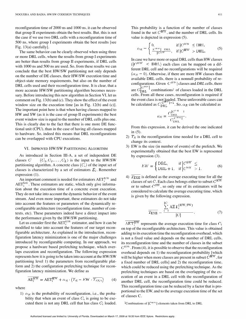
modified to take into account the features of our target recon-figurable architecture. As explained in the introduction, recon-figuration latency minimization is one of the major challengesintroduced by reconfigurable computing. In our approach, wepropose a hardware based prefetching technique, which over-laps execution and reconfiguration. The following expressionrepresents how it is going to be taken into account at theHW/SWpartitioning level 1) the parameters from reconfigurable plat-form and 2) the configuration prefetching technique for recon-figuration latency minimization. We define as
AE AET (4)
where1) is the probability of reconfiguration, i.e., the proba-bility that when an event of class is going to be exe-cuted there is not any DRL cell that has class loaded.
This probability is a function of the number of classesfound in the set , and the number of DRL cells. Itsvalue is depicted in expression (5).
ifif . (5)
In case we havemore or equal DRL cells than HW classeseach class can be mapped on a dif-
ferent DRL cell and no reconfigurations will be required. Otherwise, if there are more HW classes than
available DRL cells, there is a nonnull probability of re-configurations. Given classes andDRL cells, thereare combinations2 of classes loaded in the DRLcells. From all these cases, reconfiguration is required ifthe event class is not loaded. These unfavorable cases canbe calculated as . So, can be calculated as
From this expression, it can be derived the one indicatedin (5).
2) is the reconfiguration time needed for a DRL cell tochange its context.
3) EW is the size (in number of events) of the prefetch. Weexperimentally obtained that the best EW is representedby expression (3).
ifif . (6)
4) is defined as the average executing time for all theclasses of set . Each class belongs either to subsetor to subset , so only one of its estimators will beconsidered to calculate the average executing time, whichis given by the following expression.
(7)
represents the average execution time for classon top of the reconfigurable architecture. This value is obtainedadding to its execution time the reconfiguration overhead, whichis not a fixed value and depends on the number of DRL cells,its reconfiguration time and the number of classes in the subset
. From (4), it is possible to observe that the reconfigurationoverhead depends on 1) the reconfiguration probability [whichwill be higher whenmore classes are present in subset , fora fixed number of DRL cells] and 2) the reconfiguration time,which could be reduced using the prefetching technique. As theprefetching techniques are based on the overlapping of the ex-ecution of an event in a DRL cell with the reconfiguration ofanother DRL cell, the reconfiguration time could be reduced.This reconfiguration time can be reduced by a factor that is pro-portional to the EW, and to the average execution time of the setof classes C.2Combinations of elements taken from DRL to DRL
Authorized licensed use limited to: University of Florida. Downloaded on March 17, 2009 at 18:35 from IEEE Xplore. Restrictions apply.

412 IEEE TRANSACTIONS ON VERY LARGE SCALE INTEGRATION (VLSI) SYSTEMS, VOL. 10, NO. 4, AUGUST 2002
Fig. 14. Improvement of the initial solution.
Let us now consider the estimator, and how it is mod-ified to take into account the features of the event stream, thesoftware processor, and the HW/SW communication strategy.This is shown in the following expression:
(8)
where1) is the probability of HW/SW communication,which is a function of the number of classes found in theset . In our approach, we assume that HW/SW com-munication could also be improved using a prefetchingtechnique, which overlaps an event execution on theDRL architecture with the HW/SW communication, foran event that will be executed by the software processorin the near future (within the EW). Its value is depictedin (9). This probability represents the case in whichtwo events, that have to be executed into the softwareprocessor, are consecutive in the event stream, and thusHW/SW communication can not be hidden
(9)
2) is the average HW/SW communication time. Itrepresents the average transfer time using the system bus.
We have already introduced that our partitioning algorithmis resource constrained. The design constraints are object state
memory and class (DRL context) memory. We formulate ourproblem as maximizing the number of DE classes mapped tothe subset while 1) meeting memory and DRL area con-straints and 2) the average execution time for all classes presentin is less than its average software execution time
such that
1. SVM OSMA and DRLA DRLA
2. AET AET (10)
This new HW/SW partitioning algorithm that we areproposing is divided in three main steps: 1) obtaining an initialsolution; 2) improvement of the initial solution; and 3) classpacking in reconfiguration contexts.In order to perform this incremental approach, classes are la-
beled with an active state. We consider the following states:1) free; 2) fixed_HW and fixed_SW; and 3) tagged_HW andtagged_SW. Free state means that the class is not assigned to anysubset ( or ). Initially all classes are free. Fixed_HWmeans that the class belongs to subset , and that it cannot be moved from this subset. Fixed_SW means the same asfixed_HW but with respect to . Tagged_HWmeans that theclass belongs to subset , but that the class could be movedto . Tagged_SW means the same as tagged_HW but withrespect to .
Authorized licensed use limited to: University of Florida. Downloaded on March 17, 2009 at 18:35 from IEEE Xplore. Restrictions apply.
NOGUERA AND BADIA: HW/SW CODESIGN TECHNIQUES 413
A. Obtaining the Initial SolutionObtaining an initial solution is addressed using the list-based
partitioning algorithm presented in Section III-A. In this case,the following cost function has been used.
AET AET (11)
The difference is that in Section III-A, the algorithmwas usedto perform the HW/SW partitioning, and in this case, the algo-rithm is used to decidewhich classeswill be definitivelymappedto SW (fixed_SW) because of the limited resources. The rest ofclasses will be classified as tagged_SW, and they will be theinput to the following step of the algorithm.
B. Improvement of the Initial SolutionImprovement of the initial solution is achieved using an iter-
ative algorithm. This algorithm is based on the idea of movingclasses from the subset (concretely, the ones labeled astagged_SW) to the subset . This movement of a class ismainly determined by the expressions introduced previously atthe beginning of this section [see (4) to (9)].The pseudocode of the proposed algorithm is shown in
Fig. 14. The input to this algorithm is the sorted list of classes,where each class is labeled with a state. Classes are still orderedby the same cost function. The algorithm iterates within aloop while there is any movement. When trying to performthe movement, the algorithm initially gets the first class in thelist that is labeled as tagged_SW, and momentarily labels theclass as tagged_HW. After that, the algorithm evaluates thepartitioning of (5)–(7) assuming that the class is mapped toHW. Once this process has finished, it returns the class to itsinitial label (tagged_SW) and evaluates (9) assuming that theclass is assigned to SW.At this point it is possible to evaluate (4) and (8), for all the
preceding classes in the list. This means, to evaluate the influ-ence that will have moving a new class into the reconfigurablehardware, on the average executing time of the other classes. Foreach class, the algorithm checks if the average execution time inHW is less than the average execution time in SW. If this condi-tion is not asserted the algorithm stops, otherwise it checks thestate of the class in order to move the class to HW. This processof moving a class to HW is performed in two steps; 1) the classchanges its state from tagged_SW to tagged_HW and 2) the classchanges its state from tagged_HW to fixed_HW. Each one ofthese steps will be performed in different iterations of the al-gorithm. The mapping process is done this way to prevent thealgorithm to enter into a nonconverging state. The result of ap-plying this algorithm will be some classes labeled as fixed_HWand tagged_HW. These classes will be finally mapped to the re-configurable HW. The rest of classes will be mapped to SW.
C. Class Packing in Reconfiguration ContextsOnce the improvement of the initial solution is finished, it is
possible to perform a second type of optimization. Previously,the reconfiguration-latency problem has been addressed using aprefetching technique. However, a second possibility for min-imizing the reconfiguration latency is to reduce the number ofreconfigurations that are performed.
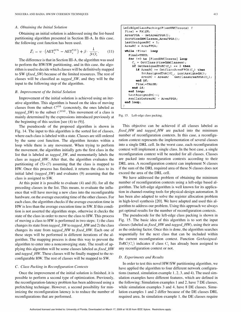
Fig. 15. Left-edge class packing.
This objective can be achieved if all classes labeled asfixed_HW and tagged_HW are packed into the minimumnumber of reconfiguration contexts. In this case, a reconfigu-ration context represents the implementation of several classesinto a single DRL cell. In the worst case, each reconfigurationcontext will implement a single class. In the best case, a singlereconfiguration context will be needed for all classes. Classesare packed into reconfiguration contexts according to theirDRL area. A reconfiguration context can implement N classesif the sum of the DRL required area of these N classes does notexceed the area of the DRL cell.We have addressed the problem of obtaining the minimum
number of reconfiguration contexts using a left-edge based al-gorithm. The left-edge algorithm is well known for its applica-tion in channel-routing tools for physical-design automation. Ithas been also adapted to solve the register allocation problemin high-level synthesis [20]. We have adapted and used this al-gorithm to address our problem. Using this approach we alwaysget optimal results for the number of reconfiguration contexts.The pseudocode for the left-edge class packing is shown in
Fig. 15. The basic idea of this algorithm is to sort the inputclasses (labeled as fixed_HW and tagged_HW), using their areaas the ordering factor. Once this is done, the algorithm searchessequentially for the next class that can be included withinthe current reconfiguration context. Function GetAssigned-ToRC indicates if class has already been assigned toany reconfiguration context or not.
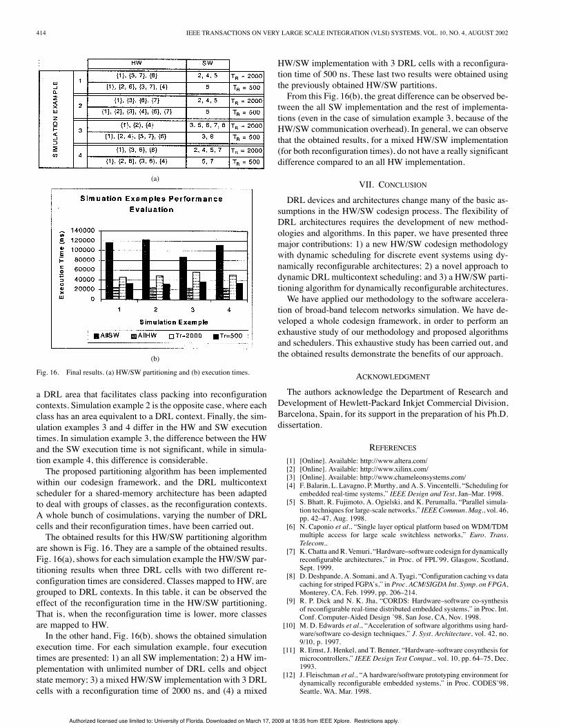
D. Experiments and ResultsIn order to test this novel HW/SW partitioning algorithm, we
have applied the algorithm to four different network configura-tions (named, simulation example 1, 2, 3, and 4). The used sim-ulation examples have different features, which are defined inthe following: Simulation examples 1 and 2, have 7 DE classes,while simulation examples 3 and 4, have 8 DE classes. Simu-lation examples 1 and 2 differ because of the DE classes DRLrequired area. In simulation example 1, the DE classes require
Authorized licensed use limited to: University of Florida. Downloaded on March 17, 2009 at 18:35 from IEEE Xplore. Restrictions apply.
414 IEEE TRANSACTIONS ON VERY LARGE SCALE INTEGRATION (VLSI) SYSTEMS, VOL. 10, NO. 4, AUGUST 2002
(a)
(b)
Fig. 16. Final results. (a) HW/SW partitioning and (b) execution times.
a DRL area that facilitates class packing into reconfigurationcontexts. Simulation example 2 is the opposite case, where eachclass has an area equivalent to a DRL context. Finally, the sim-ulation examples 3 and 4 differ in the HW and SW executiontimes. In simulation example 3, the difference between the HWand the SW execution time is not significant, while in simula-tion example 4, this difference is considerable.The proposed partitioning algorithm has been implemented
within our codesign framework, and the DRL multicontextscheduler for a shared-memory architecture has been adaptedto deal with groups of classes, as the reconfiguration contexts.A whole bunch of cosimulations, varying the number of DRLcells and their reconfiguration times, have been carried out.The obtained results for this HW/SW partitioning algorithm
are shown is Fig. 16. They are a sample of the obtained results.Fig. 16(a), shows for each simulation example the HW/SW par-titioning results when three DRL cells with two different re-configuration times are considered. Classes mapped to HW, aregrouped to DRL contexts. In this table, it can be observed theeffect of the reconfiguration time in the HW/SW partitioning.That is, when the reconfiguration time is lower, more classesare mapped to HW.In the other hand, Fig. 16(b). shows the obtained simulation
execution time. For each simulation example, four executiontimes are presented: 1) an all SW implementation; 2) a HW im-plementation with unlimited number of DRL cells and objectstate memory; 3) a mixed HW/SW implementation with 3 DRLcells with a reconfiguration time of 2000 ns, and (4) a mixed
HW/SW implementation with 3 DRL cells with a reconfigura-tion time of 500 ns. These last two results were obtained usingthe previously obtained HW/SW partitions.From this Fig. 16(b), the great difference can be observed be-
tween the all SW implementation and the rest of implementa-tions (even in the case of simulation example 3, because of theHW/SW communication overhead). In general, we can observethat the obtained results, for a mixed HW/SW implementation(for both reconfiguration times), do not have a really significantdifference compared to an all HW implementation.
VII. CONCLUSION
DRL devices and architectures change many of the basic as-sumptions in the HW/SW codesign process. The flexibility ofDRL architectures requires the development of new method-ologies and algorithms. In this paper, we have presented threemajor contributions: 1) a new HW/SW codesign methodologywith dynamic scheduling for discrete event systems using dy-namically reconfigurable architectures; 2) a novel approach todynamic DRL multicontext scheduling; and 3) a HW/SW parti-tioning algorithm for dynamically reconfigurable architectures.We have applied our methodology to the software accelera-
tion of broad-band telecom networks simulation. We have de-veloped a whole codesign framework, in order to perform anexhaustive study of our methodology and proposed algorithmsand schedulers. This exhaustive study has been carried out, andthe obtained results demonstrate the benefits of our approach.
ACKNOWLEDGMENT
The authors acknowledge the Department of Research andDevelopment of Hewlett-Packard Inkjet Commercial Division,Barcelona, Spain, for its support in the preparation of his Ph.D.dissertation.
REFERENCES[1] [Online]. Available: http://www.altera.com/[2] [Online]. Available: http://www.xilinx.com/[3] [Online]. Available: http://www.chameleonsystems.com/[4] F. Balarin, L. Lavagno, P. Murthy, and A. S. Vincentelli, “Scheduling for
embedded real-time systems,” IEEE Design and Test, Jan–Mar. 1998.[5] S. Bhatt, R. Fujimoto, A. Ogielski, and K. Perumalla, “Parallel simula-
tion techniques for large-scale networks,” IEEE Commun. Mag., vol. 46,pp. 42–47, Aug. 1998.
[6] N. Caponio et al., “Single layer optical platform based on WDM/TDMmultiple access for large scale switchless networks,” Euro. Trans.Telecom..
[7] K. Chatta and R. Vemuri, “Hardware–software codesign for dynamicallyreconfigurable architectures,” in Proc. of FPL’99, Glasgow, Scotland,Sept. 1999.
[8] D. Deshpande, A. Somani, and A. Tyagi, “Configuration caching vs datacaching for striped FGPA’s,” in Proc. ACM/SIGDA Int. Symp. on FPGA,Monterey, CA, Feb. 1999, pp. 206–214.
[9] R. P. Dick and N. K. Jha, “CORDS: Hardware–software co-synthesisof reconfigurable real-time distributed embedded systems,” in Proc. Int.Conf. Computer-Aided Design ’98, San Jose, CA, Nov. 1998.
[10] M. D. Edwards et al., “Acceleration of software algorithms using hard-ware/software co-design techniques,” J. Syst. Architecture, vol. 42, no.9/10, p. 1997.
[11] R. Ernst, J. Henkel, and T. Benner, “Hardware–software cosynthesis formicrocontrollers,” IEEE Design Test Comput., vol. 10, pp. 64–75, Dec.1993.
[12] J. Fleischman et al., “A hardware/software prototyping environment fordynamically reconfigurable embedded systems,” in Proc. CODES’98,Seattle, WA, Mar. 1998.
Authorized licensed use limited to: University of Florida. Downloaded on March 17, 2009 at 18:35 from IEEE Xplore. Restrictions apply.
NOGUERA AND BADIA: HW/SW CODESIGN TECHNIQUES 415
[13] R. Gerndt and R. Ernst, “An event-driven multi-threading architecturefor embedded systems,” in Proc. Codes/CASHE ’97, Braunschweig,Germany, Mar. 1997, pp. 29–33.
[14] R. Gupta andG.DeMicheli, “Hardware–software cosynthesis for digitalsystems,” IEEE Design Test Comput., vol. 10, pp. 29–41, Sept. 1993.
[15] S. Hauck, “Configuration prefetch for single context reconfigurable co-processors,” in Proc. ACM/SIGDA Int. Symp. FPGA, Monterey, CA,Feb. 1998, pp. 65–74.
[16] R. Hartenstein, “A decade of reconfigurable computing: A Visionaryretrospective,” in Proc. DATE’01, Munich, Germany, Mar. 2001.
[17] B. Jeong et al., “Hardware–software cosynthesis for run-time incremen-tally reconfigurable FPGA’s,” in Proc. of Asia South-Pacific Design Au-tomation Conf. (ASP-DAC’2000), Yokohama, Japan, Jan. 2000.
[18] A. Kalavade and E. A. Lee, “The extended partitioning problem: Hard-ware/software mapping, scheduling and implementation-bin selection,”J. Design Automation Embedded Syst., vol. 2, pp. 163–226, Mar. 1997.
[19] M. Kaul, R. Vemuri, R. Govindarajan, and I. Ouaiss, “An automatedtemporal partitioning and loop fission approach for FPGA based recon-figurable synthesis of DSP applications,” in Proc. Design AutomationConf. (DAC), New Orleans, LA, June 1999.
[20] F. J. Kurdahi and A. C. Parker, “REAL: A program for register alloca-tion,” in Proc. 24th Design Automation Conf., Miami, FL, June 1987.
[21] E. A. Lee, “Modeling concurrent real-time processes using discreteevents,” in Annuals Software Engineering, Special Volume on Real-TimeSoftware Engineering. Norwell, MA: Kluwer, 1998.
[22] Y. Li et al., “Hardware–software co-design of embedded reconfigurablearchitectures,” in Proc. 37th Design Automation Conf, DAC’2000..
[23] Z. Li and S. Hauck, “Don’t care discovery for FPGA configuration com-pression,” in Proc. ACM/SIGDA Int. Symp. FPGA, Monterey, CA, Feb.1999, pp. 91–98.
[24] R. Maestre, F. J. Kurdahi, N. Bagerzadeh, H. Singh, R. Hermida, and M.Fernandez, “Kernel scheduling in reconfigurable computing,” in Proc.DATE, Munich, Germany, Mar. 1999.
[25] R.Maestre, F. J. Kurdahi, M. Fernandez, and R. Hermida, “A frameworkfor scheduling and context allocation in reconfigurable computing,” inProc. Symp Syst Synthesis, San Jose, CA, Nov. 1999, pp. 134–140.
[26] D. McConnell and P. Lysaght, “Queue simulation using dynamically re-configurable FPGA’s,” in Proc. U.K. Teletraffic Symp., Scotland, U.K.,Mar. 1996.
[27] V. Mooney and G. De Micheli, ““Real time analysis and priorityscheduler generation for hardware-software systems with a synthe-sized run-time system,” in Proc. Int. Conf. Computer-Aided Design(ICCAD’97), San Jose, CA, Nov. 1997, pp. 605–612.
[28] R. Nieman and P. Marwedel, “Hardware/software partitioning using in-teger programming,” in Proc. European Design and Test Conf., Paris,France.
[29] J. Noguera, R. M. Badia, J. Domingo, and J. Sole, “Reconfigurable com-puting: An innovative solution for multimedia and telecommunicationnetwork simulation,” in Proc. 25th Euro. Conf., Milan, Italy, Sept. 1999.
[30] , “Run-time HW/SW codesign for discrete event systems using dy-namically reconfigurable architectures,” in Proc. ISSS’2000, Madrid,Spain, Sept. 2000.
[31] , “A HW/SW partitioning algorithm for dynamically reconfig-urable architectures,” in Proc. DATE’01, Munich, Germany, Mar. 2001.
[32] K. Purna andD. Bhatia, “Temporal partitioning and scheduling data flowgraphs for re-configurable computers,” IEEE Trans. Comput., vol. 48,pp. 579–590, June 1999.
[33] A. Touhafi, W. F. Brissinck, and E. F. Dirkx, “Simulation of ATMswitches using dynamically reconfigurable FPGA’s,” in Proc. FPL’98,vol. 1482, Lecture Notes in Computer Sciences, Tallin, Estonia, Sept..
[34] F. Vahid, “Modifying min-cut for hardware and software functional par-titioning,” in Codes/CASHE’97, Braunschweig, Germany, Mar. 1997,pp. 43–48.
[35] , “A three-step approach to the functional partitioning of large be-havioral processes,” in Proc. Int. Symp. Syst. Synthesis, Dec. 1998, pp.152–157.
[36] M. Vasilko and D. Ait-Boudaoud, “Scheduling for dynamically recon-figurable FPGA’s,” in Proc. Int. Workshop on Logic and ArchitectureSynthesis., Grenoble, France, Dec. 1995, IFIP TC10 WG10.5, pp.328–336.
[37] W. Wolf, “Object-oriented cosynthesis of distributed embedded sys-tems,” ACM Trans. Design Automation Electron. Syst., vol. 1, no. 3,pp. 301–314, July 1996.
Juanjo Noguera received the B.Sc. degree in computer science from theAutonomous University of Barcelona, Barcelona, Spain, in 1997. He iscurrently working toward the Ph.D. degree at the Technical University ofCatalonia, Barcelona, Spain.Since June 2001, he has been with Hewlett-Packard Inkjet Commercial Divi-
sion, Research and Development Department, San Cugat del Valles, Spain. Hewas formally with the Spanish National Center forMicroelectronics, Barcelona,Spain, and was an Assistant Professor with the Computer Architecture Depart-ment, Technical University of Catalonia. His research interests include HW/SWcodesign, reconfigurable architectures and system-on-chip design techniques.He has published papers in international conference proceedings.
Rosa M. Badia received the B.Sc. and Ph.D. degrees in computer science fromthe Technical University of Catalonia, Barcelona, Spain, in 1989 and 1994,respectively.Currently, she is an Associate Professor with the Department of Computer
Architecture, Technical University of Catalonia and Project Manager atthe CEPBA-IBM Research Institute, Barcelona, Spain. Her research inter-ests include computer-aided design tools for very large scale integration(VLSI), reconfigurable architectures, performance prediction, analysis ofmessage-passing applications, and GRID computing. She has published papersin international journals and conference proceedings.
Authorized licensed use limited to: University of Florida. Downloaded on March 17, 2009 at 18:35 from IEEE Xplore. Restrictions apply.


![A Dynamically Reconfigurable ECG Analog Front-End with a 2.5 …bioee.ucsd.edu/papers/A Dynamically Reconfigurable ECG... · 2017-06-01 · State-of-the-art low power ECG AFEs [1-2]](https://img.dokumen.tips/doc/110x75/5f13579cde6f341989253c27/a-dynamically-reconfigurable-ecg-analog-front-end-with-a-25-bioeeucsdedupapersa.jpg)