Embed Size (px)
Citation preview

������������� ����� ��� �������������������������� ������������ � !�� "##������$��� � !�� "##�����%����� ��������!�###"&#&&
'�(� �������)���
1
CYCLONETable of Contents
CO
NTEN
TS
Machine Information ..................................................................... 2
Contacting Intec ............................................................................ 3
Introduction ................................................................................... 4
Specifications ................................................................................. 5
General Overview ......................................................................... 6
The Parts ........................................................................................ 7
How the System Works Together ................................................ 8
Safety First ..................................................................................... 9
Set-Up and Operation ................................................................. 10
Generators and Extension Cords ................................................ 15
Maintenance ................................................................................. 16
Troubleshooting .......................................................................... 19
Mechanical / Electrical Drawings ............................................... 23
Claims, Damage or Loss ............................................................. 38
Warranty....................................................................................... 42
Rev 12/04

CYCLONEContacting Intec
Phone support:
Available Monday - Friday, excluding holidays. In the United States and
Canada, call (800) 666-1611, 7:00 A.M. to 5:00 P.M. Mountain Time. Ask
for technical support and one of our technicians will be glad to help
you.
On-site/off-site repair support:
Available Monday to Friday, excluding holidays. In the United States
and Canada, call (800) 666-1611, 7:00 A.M. to 5:00 P.M. Mountain time.
For authorized service centers across the United States visit our web
site, www.inteccorp.com and click on Tech Support. Authorized service
centers are independently owned and operated and are not part of
Intec. Consult the nearest service center for the hours of operation and
lead time for repair.
Website support:
Visit our web site 24/7 at www.inteccorp.com and go to the specific
model you’re wanting information on. The technical section of the web
site is constantly being updated with new information and technical
documents. If you cannot find what you are looking for please contact
us Monday - Friday, excluding holidays, in the United States and
Canada, call (800) 666-1611, 7:00 A.M. to 5:00 P.M. Mountain Time.
Contact Information:
Ph: 1-303-833-6644 1-800-666-1611 Fax: 1-303-833-6650E-mail: [email protected]
CO
NTACTIN
G IN
TEC
3

Intec appreciates your business Thank you for purchasing an Intec insulation system. Since 1977, both professional contractors and do-it-yourself equipment users have looked to Intec as the industry leader in the design and manufacture of innovative portable insulation blowing equipment. We take pride in making your job as easy and profitable as possible. The right system for your needs: Intec strives to provide you with the best combination of portability, functionality, and installation versatility to surpass your desired success. From lightweight polyethylene units with removable hoppers, to larger units with increased production rates and installation versatility, all of our durable systems are made to maximize your profit generating potential. Best-in-class Customer Service: Total ease of use extends beyond your initial purchase of an Intec system to your evolving needs thru the entire lifecycle. Both before and after the sale service is important to keep you running at peak operating capabilities. Intec’s technical team provides installation assistance in addition to maintenance suggestions and trouble-shooting support. In addition to blowing machines, Intec produces a range of accessories that will increase your productivity when dense packing, damp spraying, and installing net and blow. Thank you for partnering with Intec. We appreciate the confidence and trust you have placed in us, and wish you many profit-generating opportunities! Ray Lavallee President
INT
RO
DU
CT
ION

CYCLONESpecifications
Material All Steel construction
Powder Coat finish
Dimensions
Weight
Hopper capacity 15 lbs. (5.52 Cubic feet)
Blower(s) 1 or 2, 2 Stage, 8 amps, 104 CFM (110 VAC)
1 or 2, 2 Stage, 4 amps, 126 CFM (230 VAC)
Drive Motor 1/2 HP, 7.8 amps @ 110 VAC
1/2 HP, 4.1 amps @ 230 VAC
Power requirements 110 VAC, 60 Htz, 20 amp circuit
230 VAC, 50 Htz, 10 amp circuit
Wheels 6”
Warranty One year limited
90 days limited on electric,
blower and airlock system
Production: (100’ hose @ 16’ lift)
Cellulose
Specifications are subject to change without notice.
SPECIF
ICATIO
NS
5
173 lbs (78.6 kg)
Fiberglass 255 lbs/hr (116 kg/hr)
970 lbs/hr (441 kg/hr)
38" H x 28.5" W x 22.6" D

CYCLONEGeneral Overview
Three subsystems make up the CYCLONE:
AGITATOR AND AIRLOCK: The CYCLONE uses a 1/2
horsepower integrated motor/gearbox to drive both the agitator and
airlock. The agitator conditions the insulation material before going into
the airlock and out through the hose.
BLOWER MOTOR(S): The CYCLONE can be equipped with either
a single or dual blower to push the material through the hose and into
the attic with optimum pressure and output. The blower(s) is connected
to the air intake port of the airlock.
ELECTRICAL COMPONENTS: The CYCLONE requires a dedicated
20 or 10 amp grounded power supply depending upon voltage. Less
amperage will likely trip the circuit breaker. Always disconnect the
electrical power before beginning any maintenance. And as with all
electrical systems, never attempt to operate the CYCLONE with either the
operator or the machine standing in water.
GEN
ERAL O
VERVIE
W
6

CYCLONEThe Parts
A. Hopper: upper component of the CYCLONE where insulation is
loaded.
B. Safety Bars: prevent large pieces of insulation falling into the
agitation system.
C. Slide gate: increase or decreases the amount of material entering the
airlock.
D. Electrical Panel: on/off function of both the blower and agitator
motors.
E. Agitator Chain: transfers power from the 1/2 HP integrated motor/
gearbox to both the agitator and airlock.
F. Chain Tensioner: keeps constant tension on the chain and automat-
ically adjusts as the chain stretches.
G. Airlock: moves conditioned material from the agitator into the airflow
from the blower. Airlock seals must be maintained in good working
condition for the CYCLONE to operate at peak performance.
THE PARTS
7

CYCLONEHow the System Works Together
HO
W THE SYSTEM
W
ORKS TO
GETHER
8

CYCLONESafety First
When working with insulation, always wear a long sleeve shirt, gloves,
a hat, goggles or safety glasses for eye protection and a 3M brand #8710
nose/mouth filter (or equivalent) for respiratory protection.
Never put your hands into the hopper while the machine is running.
Keep tools and other foreign objects out of the hopper. Clean all
material out of the hopper and the hose when the job is complete.
Never leave the machine unattended while it is running. Turn “off” and
disconnect power before taking a break.
Never operate the machine if it or the operator is standing in water.
Serious injury may result.
SAFETY FIR
ST
9
ACCESSORIES YOU NEED TO WEAR...
SAFETY GLASSES OR GOGGLES
CAP
LONG-SLEEVED SHIRTGLOVES

CYCLONESet-Up and Operation
ELECTRICAL CONNECTIONS:
Before connecting the machine to electrical power, make sure all
switches are in the “off” position. Connect the supplied extension cord
to a dedicated 115/230 VAC 20 or 10 amp
grounded outlet depending upon voltage. In
the home, refrigerator or freezer outlets usually
fit the amperage requirements. If necessary,
these appliances can be temporarily unplugged,
enabling the CYCLONE to use the outlet.
Disconnecting these appliances for the short
time needed to operate the CYCLONE will not
cause spoilage. Remember to reconnect any
unplugged appliance after the job is finished.
If your job requires additional extension cords,
make sure you use only a 14/3 cord for a 25
foot run or 12/3 cord for a 50 foot extension.
STARTING:
To operate the CYCLONE the rocker
switch on the front panel must be
switched to “on” position. Each switch
will glow when motor(s) are switched to
the “on” position. Operate the blower and
agitator from the main electrical panel rocker switches.
REMOTE CONTROL (OPTIONAL):
Permanently attached to the main panel, the
remote control cord allows the attic operator to
control the on/off function of the machine. Both
the agitator and the blower can be operated
separately by the remote control.
OPERATION: To use the remote control feature
for attic operation, the switches on the main panel
must be “on”. This will allow the attic person to
control the on/off function of the machine. For
Emergency stop, depress switch to “off” position
on electrical panel.
SET-UP AN
D O
PERATIO
N
10

CYCLONESet-Up and Operation
COLD WEATHER: In colder climates the CYCLONE may be hard
to start in temperatures below 35° F. To assist in cold weather start up
keep in warm area for at least one hour before using.
HOSE SETUP: For cellulose attic applications, two and a half inch
hose produces the best results. Always use at least 100 feet of hose on
the job. Longer hose length decreases both capacity and material throw.
At 200 feet of hose, capacity and throw will be reduced by approxi-
mately 30%. If you must use a hose longer than 150 feet, reduce the
hose size to two inch diameter. For Fiberglass attic applications, the
two and a half inch inch hose produces the best results. Always use at
least 150 feet of hose on the job. Longer hose length decreases both
capacity and material throw. If you must use a hose longer than 150
feet, reduce the hose size to two inch diameter.
SLIDE GATE:
The slide gate regulates the amount
of material entering the airlock. Pull
slide gate out to increase material
flow and in to decrease. The slide
gate may be removed during
operation.
SET-UP AN
D O
PERATIO
N
11

CYCLONESet-Up and Operation
LOADING THE HOPPER: Machine may be “on” or “off” while
loading. Cellulose, place the bag of insulation material into hopper, cut
bag and break up material by hand and feed machine. Fiberglass, place
the bag inside of the hopper, cut the bag in thirds and by hand break
up the material and feed material into hopper. Dispense one third of
the contents gradually until the agitator breaks up and conditions the
material. Load the remainder of the material according to the distri-
bution rate. Empty no more than 1⁄3 bag at a time into the hopper,
until at least 1⁄4 of the material has been used before adding additional
insulation. Forcing insulation material will cause overloading, electrical
failure or possible machine damage.
Note: If the agitator stops or the circuit breaker on the electrical panel
trips, unplug the machine from electrical power. Empty all the insulation
material from hopper to locate and remove jam. After clearing, reset
the circuit breaker, reconnect electrical power and continue normal
operation.
SET-UP AN
D O
PERATIO
N
12
CYCLONESet-Up and Operation
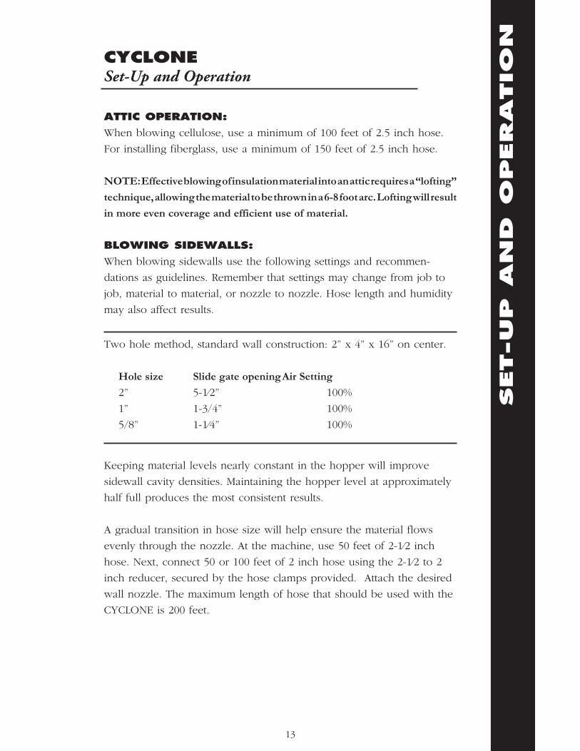
ATTIC OPERATION:
When blowing cellulose, use a minimum of 100 feet of 2.5 inch hose.
For installing fiberglass, use a minimum of 150 feet of 2.5 inch hose.
NOTE: Effective blowing of insulation material into an attic requires a “lofting”
technique, allowing the material to be thrown in a 6-8 foot arc. Lofting will result
in more even coverage and efficient use of material.
BLOWING SIDEWALLS:
When blowing sidewalls use the following settings and recommen-
dations as guidelines. Remember that settings may change from job to
job, material to material, or nozzle to nozzle. Hose length and humidity
may also affect results.
Two hole method, standard wall construction: 2” x 4” x 16” on center.
Hole size Slide gate opening Air Setting
2” 5-1⁄2” 100%
1” 1-3/4” 100%
5/8” 1-1⁄4” 100%
Keeping material levels nearly constant in the hopper will improve
sidewall cavity densities. Maintaining the hopper level at approximately
half full produces the most consistent results.
A gradual transition in hose size will help ensure the material flows
evenly through the nozzle. At the machine, use 50 feet of 2-1⁄2 inch
hose. Next, connect 50 or 100 feet of 2 inch hose using the 2-1⁄2 to 2
inch reducer, secured by the hose clamps provided. Attach the desired
wall nozzle. The maximum length of hose that should be used with the
CYCLONE is 200 feet.
SET-UP AN
D O
PERATIO
N
13

CYCLONESet-Up and Operation
If clogging or less than satisfactory compaction occurs, adjust the slide
gate inward by 1⁄2 inch increments until the situation clears. If the
problem doesn’t clear, add an additional 50 feet of 2 inch hose and
readjust your machine settings.
Insert the insulation nozzle into the lower hole of the wall cavity. Turn
blower switch “on” first, then the agitator. When the sidewall is full, the
CYCLONE blower will rev up, trying to work harder and material flow
may stop. Turning “off” first the agitator, then the blower keeps the
material from clogging the outlet hose.
Allow the blower to completely stop before removing the nozzle from
the hole. Repeat the procedure using top hole until wall cavity is full.
Caution: If you are inexperienced with blowing sidewalls you may
loosen or blow off sheetrock, or you may accidentally fill areas such as
closets.
SET-UP AN
D O
PERATIO
N
14

CYCLONEGenerators and Extension Cords
The CYCLONE will operate on power from a commercial-sized
generator. No household generators should be used due to the high
inrush requirements of the CYCLONE. Also, generators made by Honda,
Yamaha, Coleman and Generac are not recommended. While they are
of high quality, these generators do not have the inrush protection
devices necessary to start the CYCLONE and protect the generator. The
start-up requirement for a CYCLONE is 3450 watts; normal operating
requirement is 1725 watts. We recommend a generator of not less
than 4000 watts, 115 VAC. In addition, Intec recommends generators
that have a 50% power boost feature which aids the generator in high
current startups.
Running additional equipment from the same generator will increase
the total electrical requirements. Before selecting the correct size of
generator, add all tool watages up including the CYCLONE. For details
on selecting and purchasing a generator, please call INTEC.
Note: Using a generator of insufficient size will void the Warranty.
ADDING ADDITIONAL POWER CORDS.
Cord Current Capacities, Type S & SVT
Wire Size
AWG
3 Conductor
AMPS
10 25
12 20
14 15
16 10
18 7
GEN
ERATO
RS AN
D EXTEN
SIO
N CO
RDS
15

CYCLONEMaintenance
Reasonable preventive maintenance will help ensure your CYCLONE
gives you many years of satisfactory use. Cleaning the interior and
exterior of your machine and protecting its finish with a carnuba wax
will keep it looking new.
CORDS AND SWITCHES
The remote cord and switches are subject to considerable wear and tear
during normal use. Inspect all cords and switches each week for cuts or
loose connections. Repair or replace any damaged components at once
to avoid possible injury.
AIRLOCK BLOW BACK
Airlock seals are the most important component of keeping the
CYCLONE running in original condition. Airlock seals function much
like the rings in a car engine, keeping pressure and air from escaping.
When a seal or plate is damaged, air from the blower will escape back into
the hopper causing “blow back.” Blow back will result in a considerable
decrease in production.
CHECKING FOR BLOW BACK
Unplug the machine from electrical power and empty all insulation
material from the hopper. Block the hose outlet with duct tape, or use
the palm of your hand. Reconnect the power and turn on both the
blower and agitator motor. A hissing or puffing sound of air escaping
into the hopper indicates blow back. In addition, any insulation material
remaining in the airlock will blow back into the hopper, creating dust.
To remedy blow back, it is necessary to replace the airlock seals.
Note: Your CYCLONE comes from the factory preset to produce 2.5-3.0 PSI.
MAIN
TEN
AN
CE
16

CYCLONEMaintenance
AIRLOCK SEALS: Disconnect the CYCLONE from electrical power
and empty all insulation material from the hopper. Seal replacement
requires a 7/16” socket and ratchet, 6” socket extension 7/16” open-end
wrench, 1/8” & 3/16” Allen wrench, crow bar and #2 phillips screwdriver.
With the machine in an upright position, remove the cover panel to gain
access to the chain and sprockets. Loosen and remove sheet metal screw
on chain tensioner, remove chain. Using 1/8 Allen wrench, loosen set
screw on airlock sprocket. At outlet end plate (where insulation hose
attaches to machine) locate the six 1⁄4” bolts holding the end plate to
airlock. Remove the additional two socket cap screws using the 3/16”
Allen wrench. Remove end plate from machine. Note: Silicone is used to
seal the end plate and airlock connection you may need to score the silicone
seal before removing end plate. Using crow bar, wedge the crow bar
between airlock rotor and Inlet end plate, pry airlock rotor out of airlock.
Note: It may be helpful to spray a light coat of WD-40 or equivalent inside
the airlock chamber to aid in the removal of airlock rotor.
At this point the airlock rotor should be removed. Remove worn seals
from the airlock rotor and install new seal, do not over tighten seals. Over
tightening will cause the seals to bow out at the ends producing uneven
wear and premature failure. Center the seal on shaft so that there is
equal wrap at each end of the seal.
Before re-installing airlock rotor, spray entire airlock with WD-40 or
equivalent. Re-attach and tighten outlet end plate to airlock and re-seal
end plate to airlock. Note: Re-installing airlock rotor into airlock may be
difficult with new seals, see mechanical drawings section for drawing and part
numbers.
MOTOR/GEARBOX: Note: At cold temperatures below 35 F.,
oil thickens and will cause machine to start up hard. To prevent hard
startup, leave machine in warm area overnight (8 hours).
The gearbox and the airlock should be perpendicular to each other.
Proper alignment helps prevent premature wear on the chain drive
components. The gearbox is permanently sealed, no oil change is needed.
MAIN
TEN
AN
CE
17
CYCLONEMaintenance
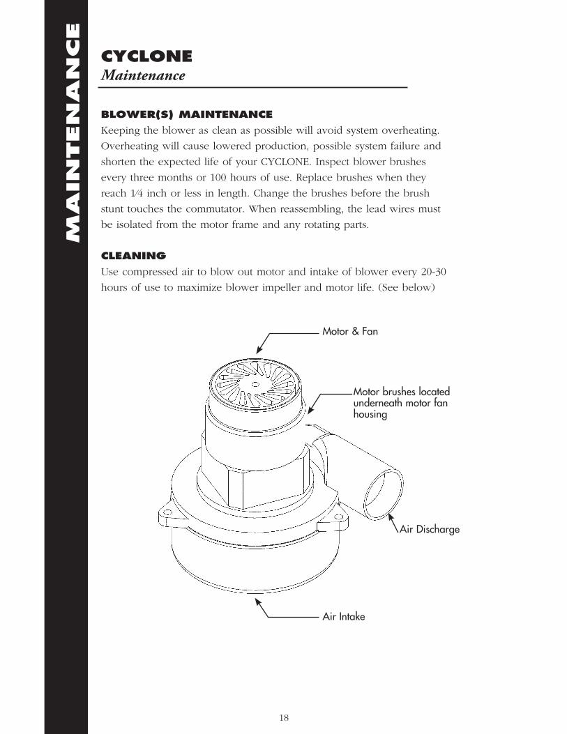
BLOWER(S) MAINTENANCE
Keeping the blower as clean as possible will avoid system overheating.
Overheating will cause lowered production, possible system failure and
shorten the expected life of your CYCLONE. Inspect blower brushes
every three months or 100 hours of use. Replace brushes when they
reach 1⁄4 inch or less in length. Change the brushes before the brush
stunt touches the commutator. When reassembling, the lead wires must
be isolated from the motor frame and any rotating parts.
CLEANING
Use compressed air to blow out motor and intake of blower every 20-30
hours of use to maximize blower impeller and motor life. (See below)
MAIN
TEN
AN
CE
18
Air Intake
Motor & Fan
Motor brushes located underneath motor fan housing
Air Discharge

CYCLONETroubleshooting
Problem Likely Cause Remedy
Agitator does not Power cord Check cord operate. not plugged in. and plug in.
Loose power cord/ Check condition of extension cord at electrical plug blades. electrical connection.
Toggle switch for agitator Flip toggle switch is not in “on” position. “on” at main panel.
Circuit breaker tripped on Push to reset tripped main panel. circuit breaker.
Jam in airlock exit tube. Disconnect electrical power. Remove hose from the exit tube. Locate jam and remove material with pliers.
Jam between blade of Disconnect agitator and airlock. electrical power. Remove insulation material from hopper. Locate jam and remove material with pliers.
Seized agitator bearing. Have bearing replaced by a qualified technician.
Main panel rocker switch Replace with original for agitator motor has factory part or with a failed. rated 20 amp @ 110V switch.
Loose wire in electrical Have the system system. inspected by a qualified technician.
Machine makes a Chain loose not Adjust chain ratcheting noise when engaged with sprockets. tensioner or re-align turned on. chain & sprockets.
TRO
UBLESHO
OTIN
G
19

CYCLONETroubleshooting
Problem Likely Cause Remedy
Decreased material Worn airlock seals. Inspect seals for throw. tears or cuts.
Kink in hose. Run hose as straight as possible to help maintain production.
Excess air leaking into Inspect seals for tears hopper. or cuts. See mainten- ance section to replace or adjust as necessary.
Machine does not run. No power. Check source of electrical power. Possible tripped circuit breaker.
Main panel circuit Push to reset. breaker tripped.
Air, but no material, Slide gate closed. Open to operating comes out of hose. position.
Bridging (air pocket Turn machine “off” in hopper). and disconnect from electrical power. Redistribute material in hopper. Reconnect to electrical power.
Circuit breaker tripped on Push to reset. main panel.
Jam between blade of Disconnect electrical agitator and airlock. power. Remove insulation material from hopper. Locate jam and remove material with pliers.
Blower does not Blower rocker switch Check wiring, replace operate. may be worn rocker switch using or defective. Factory original part.
TRO
UBLESHO
OTIN
G
20

CYCLONETroubleshooting
Problem Likely Cause Remedy
Loose power cord/extension Check condition of cord at electrical system. electrical plug blades.
Loose wire in electrical Have the system system. inspected and repaired by a qualified technician.
Worn brushes in Have the brushes blower motor. inspected and replaced by a qualified technician.
Agitator trips Low voltage. CYCLONE requires a circuit breaker. minimum of 20 amps @ 115V. Relocate power cord to a dedicated 20 amp circuit.
Incorrect size extension cord. For an additional 25’ run, use 14/3 cord. For a 50’ run use 12/3 cord.
Pushing down on material Do not push down on in hopper. insulation while filling hopper.
Wet insulation material in Do not use wet hopper. material. Disconnect electrical power and remove wet material.
Worn or frozen airlock Have bearing checked bearing. and replaced by a qualified technician.
Blower trips circuit Low voltage. Blower requires a breaker at minimum of 20 power source. amps @ 115V. Use a dedicated refrig- erator outlet or equivalent.
TRO
UBLESHO
OTIN
G
21

CYCLONETroubleshooting
Problem Likely Cause Remedy
Incorrect extension cord. For an additional 25’ run, use 14/3 cord. For a 50’ run use 12/3 cord.
Operator in attic keeps Static electricity from Mix half-and-half getting shocked. insulation. solution of water and fabric softener. Mist into insulation while loading hopper. Note: excess moisture will cause jamming.
TRO
UBLESHO
OTIN
G
22

MECHAN
ICAL DRAW
ING
S
23
MECHAN
ICAL DRAW
ING
S
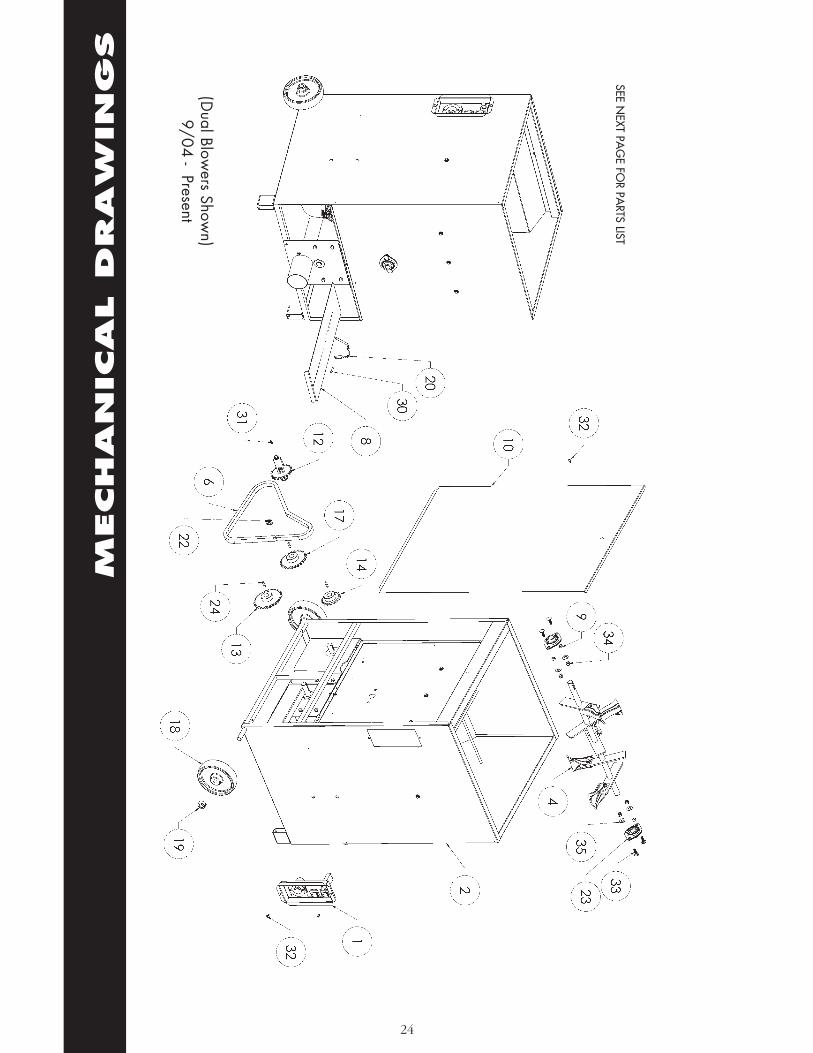
24
SEE NEXT PA
GE FO
R PARTS LIST
(Dual Blow
ers Shown)
9/04 - Present
MECHAN
ICAL DRAW
ING
S
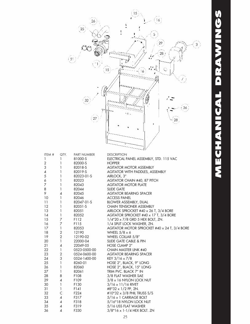
ITEM # QTY. PART NUMBER DESCRIPTION1 1 81000-S ELECTRICAL PANEL ASSEMBLY, STD. 115 VAC2 1 82000-S HOPPER3 1 82018-S AGITATOR MOTOR ASSEMBLY4 1 82019-S AGITATOR WITH PADDLES, ASSEMBLY5 1 82023-01-S AIRLOCK, 3”6 1 82023 AGITATOR CHAIN #40, 87 PITCH7 1 82043 AGITATOR MOTOR PLATE8 1 82044 SLIDE GATE9 4 82045 AGITATOR BEARING SPACER10 1 82046 ACCESS PANEL11 1 82047-01-S BLOWER ASSEMBLY, DUAL12 1 82051-S CHAIN TENSIONER ASSEMBLY13 1 82051 AIRLOCK SPROCKET #40 x 26 T, 3/4 BORE14 1 82052 AGITATOR SPROCKET #40 x 17 T, 3/4 BORE15 7 F112 1/4*20 x 7/8 GRD 5 HEX BOLT, ZN.16 7 F115 1/4 SPLIT LOCK WASHER, ZN.17 1 82053 AGITATOR MOTOR SPROCKET #40 x 24 T, 3/4 BORE18 2 12190 WHEEL 5/8 x 619 2 12190-02 WHEEL COLLAR 5/8”20 1 22000-04 SLIDE GATE CABLE & PIN21 4 22049-05 HOSE CLAMP 2”22 1 0523-0500-00 CHAIN MASTER LINK #4023 2 0524-0600-00 AGITATOR BEARING SPACER24 3 0524-1400-00 KEY 3/16 x 7/825 1 8260-01 HOSE 2”, BLACK, 9” LONG26 1 82060 HOSE 2”, BLACK, 15” LONG27 1 82061 TRIM PVC. BLACK 7” IN28 8 F108 3/8 FLAT WASHER SAE29 4 F109 3/8 x 16 NYLON LOCK NUT30 1 F130 3/16 x 11/16 RIVET31 1 F141 #8*32 x 1/2 PP, 2N.32 C F224 #10*32 x 3/8 PHIL TRUSS S/S33 4 F317 5/16 x 1 CARRIAGE BOLT34 4 F318 5/16*18 NYLON LOCK NUT35 4 F319 5/16 USS FLAT WASHER36 4 F330 3/8*16 x 1-1/4 HEX BOLT. ZN
25

MECHAN
ICAL DRAW
ING
S
ITEM #
Q
TY. PA
RT NU
MBER
DESC
RIPTION
1 1
82028-S A
IRLOC
K ROTO
R ASSM
. W/SEA
LS2
1 82029-S
AIRLO
CK TU
BE3
1 82032-S
INLET PLA
TE 2”4
1 82036-S
1/4*20 X 7/8 HEX C
AP SC
REW5
8 F112
1/4 X 20 X 7/8” GRD
5 HEX, ZN
6 12
F115 1/4 SPLIT LO
CK W
ASH
ER, ZN7
2 82041-S
AIRLO
CK BEA
RING
WITH
SNA
P RING
8 4
F159 1/4 FLA
T WA
SHER, ZN
9 4
F415 1/4*20 X 1SO
CKET C
AP SC
REW
Airlock A
ssm.
9/04 - Present
26

MECHAN
ICAL DRAW
ING
S
27
ITEM
#
QTY
. PA
RT N
UM
BER
DES
CRI
PTIO
N1
1 82
024-
S A
IRLO
CK
ROTO
R W
ELD
MEN
T2
6 92
18
AIR
LOC
K SE
AL,
18”
3 6
8202
7 A
IRLO
CK
ROTO
R PL
ATE
, BA
CK
4 18
F3
43
8*32
X 3
/4”
PHIL
PAN
M/S
, ZN
5 18
F1
20
8*32
NYL
ON
LO
CK
INSE
RT N
UT
6 4
9218
FEL
T FE
LT S
EAL
1-1/
2”7
2 92
18 F
OA
M
FOA
M R
UBB
ER S
EAL
1-1/
2”
Airl
ock
Roto
r Ass
m.
9/04
- P
rese
nt

MECHAN
ICAL DRAW
ING
S
28
ITEM #
Q
TY. PA
RT NU
MBER
DESC
RIPTION
1 1
82015-S BLO
WER BRA
CKET
2 2
12002-01 BLO
WER 104 C
FM, 115 V
AC
50/60 HZ
3 6
82048 BLO
WER STA
ND
-OFF
4 6
F159 1/4” FLA
T WA
SHER, ZN
5 6
F115 1/4” SPLIT LO
CK W
ASH
ER, ZN7
6 F226
1/4*20 x 3-1/2” HEX BO
LT, ZN
9/04 - PresentBlow
er(s)(D
ual Blower Show
n)

MECHAN
ICAL DRAW
ING
S
29
ITEM
#
QTY
. PA
RT N
UM
BER
DES
CRI
PTIO
N1
1 82
019
AG
ITA
TOR,
ASS
M2
5 82
022
AG
ITA
TOR
PAD
DLE
3 5
F112
1/
4*20
x 7
/8 G
RD 5
HEX
BO
LT, Z
N4
10
F159
1/
4 FL
AT
WA
SHER
5 5
F114
1/
4*20
LO
CK
NU
T
9/04
- P
rese
ntA
gita
tor

MECHAN
ICAL DRAW
ING
S
30
9/04 - PresentChain Tensioner
ITEM # QTY. PART NUMBER DESCRIPTION1 1 0524-0701-00 CHAIN TENSIONER SPROCKET #40X19 T2 1 82047 CHAIN TENSIONER SPACER3 1 0524-0700-00 CHAIN TENSIONER BRACKET4 1 F108 3/8” FLAT WASHER, ZN
NOTE: ITEM THREE INCLUDES ALL HARDWARE FOR ASSEMBLY

MECHAN
ICAL DRAW
ING
S
31
9/04 - PresentStandard Electrical 110 VAC
ITEM # QTY. PART NUMBER DESCRIPTION1 1 81001-S ELECTRICAL PANEL 2 2 F119 #8* 32-3/8” PP, ZN3 1 21045-02 CIRCUIT BREAKER BUTTON SEAL4 1 21011 ELECTRICAL FLANGE RECEPTACLE5 1 81008 PLUG 7/8”6 1 81007 ROCKER SWITCH GREEN6A 1 81007-01 ROCKER SWITCH RED7 1 81004 CIRCUIT BREAKER 10 A8 1 81003 ELECTRICAL PANEL STICKER (ENGLISH)

MECHAN
ICAL DRAW
ING
S
32
9/04 - Present Std Electrical w/power cord 115
VAC
ITEM # QTY. PART NUMBER DESCRIPTION1 1 81001-S ELECTRICAL PANEL2 2 F119 #8* 32-3/8” PP, ZN3 1 21045-02 CIRCUIT BREAKER BUTTON SEAL4 1 81002 RECEPTACLE COVER PLATE5 1 81003 ELECTRICAL PANEL STICKER (ENGLISH)6 1 F132 STRAIN RELIEF LOCK NUT, 1/2”7 1 21008-02 STRAIN RELIEF ALUMINUM, 1/2”8 1 81007 ROCKER SWITCH GREEN8A 1 81007-01 ROCKER SWITCH RED9 1 81008 PLUG 7/8”10 2 81007 CIRCUIT BREAKER 10A11 1 81009-S POWER CORD ASSM, 25 FT

ELECTRIC
AL DRAW
ING
S
33
9/04 - PresentWiring Diagram for STD Electrical OPT Electrical
W/ Pwr Cord

9/04 - Present(Optional) Electrical W/ Remote
Cord 110 VAC
ITEM # QTY. PART NUMBER DESCRIPTION1 1 81001-S ELECTRICAL PANEL W/FASTENERS2 2 F119 #8* 32-3/8” PP, ZN3 1 21045-02 CIRCUS BREAKER BUTTON SEAL4 1 21011 ELECTRICAL FLANGE RECEPTACLE5 1 81007 ROCKER SWITCH, GREEN5A 1 81007-01 ROCKER SWITCH, RED6 1 81004 CIRCUIT BREAKER 10 A7 1 81003 ELECTRICAL PANEL STICKER (ENGLISH)8 1 21008-02 STRAIN RELIEF ALUMINUM, 1/2”9 1 F132 STRAIN RELIEF LOCK NUT, 1/2”10 1 K11081-S REMOTE CORD ASSM, 100 FEET
MECHAN
ICAL DRAW
ING
S
34

MECHAN
ICAL DRAW
ING
S
35
9/04 - Present(Optional) Electrical
W/ Power Cord & Remote115 VAC
ITEM # QTY. PART NUMBER DESCRIPTION1 1 81001-S ELECTRICAL PANEL W/FASTENERS2 2 F119 #8* 32-3/8” PP, ZN3 1 81007 ROCKER SWITCH, GREEN3A 1 81007-01 ROCKER SWITCH, RED4 1 81004 CIRCUIT BREAKER 10 A5 1 21045-02 CIRCUIT BREAKER BUTTON SEAL6 1 81002 RECEPTACLE COVER PLATE7 1 81003 ELECTRICAL PANEL STICKER (ENGLISH)8 2 F132 STRAIN RELIEF LOCK NUT, 1/2”9 2 21008-02 STRAIN RELIEF ALUMINUM, 1/2”10 1 81009-S REMOTE CORD ASSM, 25 FEET11 1 K11081-S REMOTE CORD ASSM, 100 FEET

36
ELECTRIC
AL DRAW
ING
S9/04 - Present
Wiring Diagram for Electrical W/ Remote Cord
115 VAC

37
ITEM # PART NUMBER DESCRIPTION22............21008-0 .................. REMOTE BOX 3/4” W/HOLE23............21008-09 ................ STRAIN RELIEF, ALUM. 3/4”24............11081 ..................... REMOTE CORD 16/4 x 100’ (ONLY)25............01009 ..................... REMOTE BOX SHIELD STICKER26............11008-06-01-S ........ REMOTE BOX ROCKER SWITCH26A .........21021-S .................. REMOTE BOX ROCKER SWITCH ASSM.27............RR21004 ................. REMOTE BOX 3/4” SHIELD W/O STICKER28............ F119 ....................... 8* 32 x 3/8 PP ZN29............ F122 ....................... 6* 32 x 3/8 PP ZN30............ F124 ....................... 6* 32 NYLON INSERT LOCK NUT31............ F153 ....................... #6 RING TERMINAL, BLUE32............ F136 ....................... BUTT SPLICE, BLUE33............ F230 ....................... SHRINK TUBE 3/16 x 1/4”, WHITE34............ F231 ....................... SHRINK TUBE 3/16 x 1/4”, RED
Remote box Assm.9/04-present
MECHAN
ICAL DRAW
ING
S

�������������������� ����� ����
*�*
�%+'�,��-+,.'/01
������ ����������� �� ���������������������������
���������� �
���
���
�������
�������������� �����������
�������
����� �� ��
�����
������
����
��
����
�������
������
��
�
��
����
� ���
����!"�
#�$������%
����"�&���
����'����%�(���������
)��$��
"������
���������������������
��������*��+�$����������%�������
��������$ ����$�������� ��,�-���������
���������
����
(���� �*���
*���
��������#���
&����%�.��
�������������
�����
*��+�"�
&��
$ ���
�/�"
&����%
� &
�����������
� &
�����������
�����������������
�0�������
�����$ ���
*��+
$ ���
.�����������������,�%�
����� � ,,�,�&����%�.��
�/
��
1�
��� ��
���
��/�!"�
���!"�
�����
*��+
*��+
� !��
���"���������
��*�#���
&����%�.��
"������
�/
��
1�
��#
� � � � � 1 2 � 3 �/ �� ��
$ ����"�&��
&����"�&��
���4*��+�"�&��
�������4$ ����"�&��
*��+
��%
�
�����
��
������
�����%
$ ���
������
��������
�� �
�
�1
"���$���,����"�
&�����5�����,�
����%��� ��$�,�
"�&���*��+
"�&���$ ���
"�&���*���
"�&�����%
"�&�����%
"�&���*���
"�&���$ ���"�&���*��+
"�&��������
"�&��������
*��+
$ ���*��+
$ ���
*��+
*��+
$ ���
$ ���
$ ���
$ ���
$ ���
$ ���
��%
*��+
��$
%�&�����$
������������'
60''7
6).0�8(7
6"&9�"�0(7
60�7
60''7
60�7
&����%)��
$ ���
�����
*��+
��%
$ ���
*��+
��%
�����
�

������ � !�� �"# �$%�&#� �'�#�� �($���������������������������������������������)��������������������#��������*��+�,�-����.���������������������������������������������/��������������������#�����&�-0�1�,20����*�*1��������������������������������������������/��������������������#����0�&�-�'3���*0�1�,2����*�*,��������������������������������������������4��������������������#�����&�-� ������'5��3�'� �/��������������������������������������������+��������������������'5��3�"���0�6���*�#�7� ������#�����&�-����*�*+�����������������������������������������6��8���������������������)91��-�1�)2�'���54�����������������������������������������:���)��'�������������#��������*�"�������*�*0��+�,�-����.
*�*
�%+'�,��-
+,.'/01
�������������������� ����� ����
�
2
3
4
5
7
6
&6(#�(�#" �$;��%���$
���������������� ���������� ��������� ������6�#' 0� %#$�($� <�&=(�#��������� ��� ��������������������� ����������6�#' 0� %#$�(66� <�";� " (#���������������
$( >������� ��������� ��� ����������������� ����������������������������������� � ���� �������������������������
"$ '���% �=�?"#�=��%��(
����� ������������������������ ��� ������� �������#��#(�$��$�"�=��(��#'(#������������ ��� ������ ��� � �������� �������#��#(�"�";%�=�";� "�(#���������������������
���(# "$ >�������� � ������ ��� ��������������!����������������� �����������������"�������� �����#���������� ��������������������� $�������������������������

CYCLONEClaims, Damage or Loss
These goods were carefully packed and thoroughly inspected before
leaving our factory. Responsibility for its safe delivery was assumed by
the carrier upon acceptance of the shipment. Inspect shipment carefully
on the arrival for damage to contents, shortages or equipment. In case
of damage save container and packing material for inspection. Claims
for loss or damage sustained in transit must, therefore, be made upon
the carrier, as follows:
1. CONCEALED LOSS OR DAMAGE. Concealed loss or
damage means loss or damage which does not become apparent until
the merchandise has been unpacked. The contents may be damaged
in transit due to rough handling even though the carton may not show
external damage. When the damage is discovered upon unpacking
make a written request for inspection by the carrier’s agent within ten
days of the delivery date. Then file a claim with the carrier since such a
claim is the carrier’s responsibility.
2. VISIBLE LOSS OR DAMAGE. Any external evidence of
loss or damage must be noted on the freight bill or the express receipt,
and signed by the carrier’s agent. Failure to adequately describe such
external evidence of loss or damage may result in the carrier refusing
to honor a damage claim. The form required to file such a claim will be
supplied by the carrier.
3. SHORTAGE. If the number of containers in the shipment does
not correspond with the transportation bill, obtain carrier’s notation
of shortage and signature on transportation bill. When the number of
containers is correct, but there is indication of pilferage, notify carrier in
writing with a complete list of missing merchandise.
Claims for loss or damage must be filed with the carrier by the
consignee within 24 hours after receipt of goods. We will assist you in
every possible manner but cannot be responsible for the collection of a
claim or the cost of replacement of the damaged goods.
If you have any questions regarding the above information please feel
free to contact an INTEC representative.
CLAIM
S, DAM
AG
E O
R LO
SS
38

CYCLONEClaims, Damage or Loss
RETURNS
We at INTEC sincerely hope the merchandise you have just received
is in excellent condition and satisfies your expectations. If not, please
look below and follow the instructions which apply to your particular
situation.
MERCHANDISE IS DAMAGED.
If the carrier is UPS:
Keep the merchandise in the original packing materials and carton.
Call UPS at (800) 742-5877 or contact them using their web address:
www.ups.com/using/custserv/ to notify them of the damaged package.
Fill out the information sheet on the following page and mail or fax it
to the attention of the Shipping Department.
Upon return of this form and/or the damaged merchandise, we will
send a replacement or credit your account.
Other than UPS:
Keep the merchandise in the original packing materials and carton.
Call the Shipping Department at the number on the following page for
further instructions.
Upon return of this form and/or the damaged merchandise by the
carrier, we will send you a replacement or credit your account. Do not
return any merchandise through the U.S. Post Office.
MERCHANDISE IS PERSONALLY
UNSATISFACTORY TO YOU.
You may return the merchandise, along with a RMA number on outside
of carton and a copy of your invoice to the Shipping Department at the
address provided on the next page. Upon its return intact, we will send
a refund or credit your account. A restocking fee may be charged.
CLAIM
S, DAM
AG
E O
R LO
SS
39

CYCLONEClaims, Damage or Loss
SHIPMENTS TO FACTORY
All shipments to the factory must have a RMA number on the outside
of the carton. You will be given a RMA number when you contact the
Sales Department. The RMA is the only way to track and assure that
your request is handled properly. If you received an invoice with your
merchandise, please include a copy of the invoice with all returned
materials.
Company Name___________________________________________
Contact Name ____________________________________________
Phone________________________ Fax ________________________
Address __________________________________________________
City_____________________ State____ Zip ________________________
Invoice Number________________ RMA Number _______________
Shipping Department Ph: 1-303-833-6644 INTEC 1-800-666-1611 Fax: 1-303-833-6650 E-mail: [email protected]
REPLACEMENT PARTS
When you call INTEC, please have available the model number and
serial number of your machine, as well as description of the defective
part or an explanation of the defect.
We will issue a Return Merchandise Authorization (RMA) number and
instructions to return the defective part. All shipments to INTEC must
be sent via UPS, except in the case of complete machines, when a
common carrier should be used. The warranty on your machine does
not cover freight or labor charges. All shipments to the factory or service
center must be freight prepaid. No freight collect shipments will be
accepted without prior approval.
CLAIM
S, DAM
AG
E O
R LO
SS
40
4040 Kodiak CourtFrederick, CO 80504

CYCLONEClaims, Damage or Loss
Your RMA number must appear on the outside of any returned cartons.
We assume no responsibility for incoming lost or untraceable shipments.
RMA numbers expire 30 days after issue date. Shipments received after
the 30-day expiration period may not be credited.
We will repair or replace, at our option, any returned part found to be
defective in materials or workmanship under the terms of our limited
warranty. Repaired or replaced parts will be returned to you freight
collect.
If we determine the part failure was due to misuse, alteration,
negligence, accident or operating beyond rated capacity, we will contact
you. At your option, we will send you a new part at the prevailing
price or return the failed part to you. All shipments from the factory are
sent freight collect.
If you require a replacement part prior to a warranty decision, we will
send the part to you at the prevailing price, under your current terms.
When we receive the defective part and a warranty decision has been
made, INTEC will either issue a credit to your account or return the
failed part to you.
Shipping Department Ph: 1-303-833-6644 INTEC 1-800-666-1611 Fax: 1-303-833-6650 E-mail: [email protected]
CLAIM
S, DAM
AG
E O
R LO
SS
41
Frederick, CO 80504
4040 Kodiak Court

CYCLONEWarranty
It is expressly understood and agreed that no officer, agent, salesman or employee of the Manufacturer INTEC has the authority to obligate the Manufacturer by any terms, stipulations, or conditions not herein expressed; that all previous representations and agreements, either verbal or written, referring to the machinery and equipment, which is the subject of this Warranty, are hereby superseded and canceled, and that there are no promises or agreements outside of this Warranty agreement. Furthermore, the Manufacturer hereby disclaims any implied warranties of merchantability, or implied warranties of fitness for a particular purpose.
With the above understanding, the Manufacturer’s CYCLONE insulation blowing machine is sold with the following one (1) year Limited Warranty, and no other:
a) Manufacturer warrants to the original purchaser that the machine is well made, of good material and durable; but only if the machine is operated and maintained in accordance with this Operator’s Manual and the Maintenance Manual. This Warranty is void if the machine is not so operated and maintained, or if the machine is used for blowing materials other than those which are intended to be used with the machine.
b) Manufacturer guarantees the machine to be free from manufacturing defects at the time of shipment, and to remain free from defects when operated under normal use, for a period of one (1) year from the date of factory shipment, with the exception of the blower, electrical and air lock components, which are guaranteed for a period of ninety, (90) days from date of factory shipment.
c) This Warranty shall not apply to any machine or component part which, in the opinion of the Manufacture, has been altered, subject to misuse, negligence, accident or operated beyond factory rated capacity. All requested Warranty work shall be performed at Manufacturer’s factory or by an Authorized Factory Service Facility. Failure to have the Warranty work done at Manufacturer’s factory or by an Authorized Factory Service Facility will void this Warranty. Manufacturer will bear full responsi-bility to repair or replace, at its option, without charge to the original purchaser, any part which, in the Manufacturer’s opinion, is found to be defective.
d) All parts claimed defective by original purchaser shall be returned, properly identified, to Manufacturer’s factory or Authorized Factory Service facility, freight prepaid. All replacement, repaired or non-defective parts will be returned to purchaser, freight collect. Manufacturer will supply replacement parts prior to receipt of my parts claimed defective, only with the understanding that such replacement parts will be shipped to purchaser at the then prevailing price of said part, C.O.D., freight collect. Manufacturer will reimburse cost of any such part only after receipt and inspection, and finding said part defective.
e) Manufacturer’s liability is expressly limited to the repair or replacement of defective parts set forth in this Warranty. All other damages and warranties, statutory or otherwise, being waived by original purchaser as a condition of sale and purchase
WARRAN
TY
42