Embed Size (px)
Citation preview
CN
C 8
070
(REF: 1007)
HARDWARE CONFIGURATION
(Ref: 1007)

MACHINE SAFETY
It is up to the machine manufacturer to make sure that the safety of the machineis enabled in order to prevent personal injury and damage to the CNC or to theproducts connected to it. On start-up and while validating CNC parameters, itchecks the status of the following safety elements:
• Feedback alarm for analog axes.• Software limits for analog and sercos linear axes.• Following error monitoring for analog and sercos axes (except the spindle)
both at the CNC and at the drives.• Tendency test on analog axes.
If any of them is disabled, the CNC shows a warning message and it must beenabled to guarantee a safe working environment.
FAGOR AUTOMATION shall not be held responsible for any personal injuries orphysical damage caused or suffered by the CNC resulting from any of the safetyelements being disabled.
HARDWARE EXPANSIONS
FAGOR AUTOMATION shall not be held responsible for any personal injuries orphysical damage caused or suffered by the CNC resulting from any hardwaremanipulation by personnel unauthorized by Fagor Automation.
If the CNC hardware is modified by personnel unauthorized by Fagor Automation,it will no longer be under warranty.
COMPUTER VIRUSES
FAGOR AUTOMATION guarantees that the software installed contains nocomputer viruses. It is up to the user to keep the unit virus free in order toguarantee its proper operation.
Computer viruses at the CNC may cause it to malfunction. An antivirus softwareis highly recommended if the CNC is connected directly to another PC, it is partof a computer network or floppy disks or other computer media is used to transmitdata.
FAGOR AUTOMATION shall not be held responsible for any personal injuries orphysical damage caused or suffered by the CNC due a computer virus in thesystem.
If a computer virus is found in the system, the unit will no longer be under warranty.
All rights reserved. No part of this documentation may be transmitted,transcribed, stored in a backup device or translated into another languagewithout Fagor Automation’s consent. Unauthorized copying or distributing of thissoftware is prohibited.
The information described in this manual may be changed due to technicalmodifications. Fagor Automation reserves the right to make any changes to thecontents of this manual without prior notice.
All the trade marks appearing in the manual belong to the corresponding owners.The use of these marks by third parties for their own purpose could violate therights of the owners.
It is possible that CNC can execute more functions than those described in itsassociated documentation; however, Fagor Automation does not guarantee thevalidity of those applications. Therefore, except under the express permissionfrom Fagor Automation, any CNC application that is not described in thedocumentation must be considered as "impossible". In any case, FagorAutomation shall not be held responsible for any personal injuries or physicaldamage caused or suffered by the CNC if it is used in any way other than asexplained in the related documentation.
The content of this manual and its validity for the product described here has beenverified. Even so, involuntary errors are possible, thus no absolute match isguaranteed. Anyway, the contents of the manual is periodically checked makingand including the necessary corrections in a future edition. We appreciate yoursuggestions for improvement.
The examples described in this manual are for learning purposes. Before usingthem in industrial applications, they must be properly adapted making sure thatthe safety regulations are fully met.
Hardware configuration
CNC 8070
(REF: 1007)
·3·
I N D E X
About the product ....................................................................................................................... 7Declaration of conformity ............................................................................................................ 9Version history .......................................................................................................................... 11Safety conditions ...................................................................................................................... 13Warranty terms ......................................................................................................................... 17Material returning terms ............................................................................................................ 19CNC maintenance .................................................................................................................... 21Related documentation ............................................................................................................. 23
CHAPTER 1 PREVIOUS INFORMATION.
CHAPTER 2 HARDWARE STRUCTURE.
2.1 Possible configurations. ............................................................................................... 29
CHAPTER 3 HEAT DISSIPATION. CENTRAL UNIT (CPU) ENCLOSURE.
3.1 Heat dissipation models. .............................................................................................. 35
CHAPTER 4 CENTRAL UNITS ICU - MCU.
4.1 Technical characteristics. ............................................................................................. 394.2 MCU central unit dimensions. ...................................................................................... 414.3 MCU-PCI central unit dimensions. ............................................................................... 424.4 ICU central unit dimensions. ........................................................................................ 434.4.1 Dimensions of the central unit without monitor. ....................................................... 434.4.2 Dimensions of the central unit with LCD-10 monitor. ............................................... 444.4.3 Dimensions of the central unit with LCD-10K monitor. ............................................. 454.4.4 Dimensions of the central unit with LCD-15 monitor. ............................................... 464.5 Dimensions and characteristics of the enclosure. ........................................................ 474.6 Elements (connectors). ................................................................................................ 504.6.1 Peripheral board. ...................................................................................................... 504.6.2 Expansion board. ..................................................................................................... 534.6.3 CPU board. .............................................................................................................. 564.6.4 PCI expansion board (only for the MCU model). ..................................................... 584.6.5 Operator panel (only LCD-10K) ............................................................................... 604.6.6 Digital inputs and outputs. Electrical characteristics. ............................................... 614.6.7 Feedback inputs. Technical characteristics and connection. ................................... 624.7 Power connection. ....................................................................................................... 644.8 housing for the compact flash and battery-powered RAM memory. ............................ 654.9 Insert the board into the PCI expansion (only in MCU models). .................................. 664.10 RS232 serial line connection. ...................................................................................... 684.11 RS422 serial line connection. ...................................................................................... 704.12 RS485 serial line connection. ...................................................................................... 724.13 Probe connection. ........................................................................................................ 744.14 Connection to an Ethernet network. ............................................................................. 76
CHAPTER 5 LCD-15SVGA. PASSIVE MONITOR " LCD15-SVGA".
5.1 Possible configurations. ............................................................................................... 785.2 Technical characteristics. ............................................................................................. 795.3 Hardware dimensions. ................................................................................................. 805.4 Dimensions and characteristics of the enclosure. ........................................................ 815.5 Elements (connectors). ................................................................................................ 825.6 Overall connection. ...................................................................................................... 83
CHAPTER 6 OP-PANEL-H/E MODULE. KEYBOARD AND OPERATOR PANEL.
6.1 Hardware dimensions. ................................................................................................ 856.2 Dimensions and characteristics of the enclosure. ........................................................ 866.3 Elements (connectors). ................................................................................................ 87

·4·
Hardware configuration
CNC 8070
(REF: 1007)
CHAPTER 7 KB-PANEL-H MODULE. INDEPENDENT KEYBOARD.
7.1 Hardware dimensions. ................................................................................................ 917.2 Dimensions and characteristics of the enclosure. ....................................................... 927.3 Elements (connectors). ................................................................................................ 93
CHAPTER 8 JOG-PANEL MODULE. INDEPENDENT OPERATOR PANEL.
8.1 Hardware dimensions. ................................................................................................ 958.2 Dimensions and characteristics of the enclosure. ....................................................... 968.3 Elements (connectors). ................................................................................................ 97
CHAPTER 9 MOUSE MODULE.
9.1 Hardware dimensions. .............................................................................................. 101
CHAPTER 10 RIO70 REMOTE MODULES. (CANFAGOR PROTOCOL).
10.1 Dimensions and mounting of the modules. ................................................................ 10410.2 Consumption of the remote modules. ........................................................................ 10610.3 Power Supply. ............................................................................................................ 10710.3.1 Elements (connectors). .......................................................................................... 10810.4 Digital inputs and outputs. ......................................................................................... 11010.4.1 Elements (connectors). .......................................................................................... 11110.5 Analog inputs and outputs. ........................................................................................ 11210.5.1 Elements (connectors). .......................................................................................... 11310.6 Feedback inputs (counter). ........................................................................................ 11410.6.1 Elements (connectors). .......................................................................................... 11510.7 Electrical characteristics of the inputs and outputs. ................................................... 11610.8 Feedback inputs. Technical characteristics and connection. ..................................... 11710.9 Numbering of the digital inputs and outputs. ............................................................. 11910.10 Numbering of the analog inputs and outputs and of the feedback inputs. ................. 12110.11 Probe connection. ...................................................................................................... 122
CHAPTER 11 RIO5 REMOTE MODULES. (CANOPEN PROTOCOL).
11.1 Dimensions and mounting of the modules. ................................................................ 12611.2 Power supply. ............................................................................................................ 12711.2.1 Elements (connectors). .......................................................................................... 12911.3 Digital inputs and digital outputs (single module). ..................................................... 13311.3.1 Elements (connectors). .......................................................................................... 13411.4 Digital inputs and digital outputs (double module). .................................................... 13511.4.1 Elements (connectors). .......................................................................................... 13611.5 Electrical characteristics of the inputs and outputs. ................................................... 13711.6 Numbering of the digital inputs and outputs. ............................................................. 13911.7 Numbering of the analog inputs and outputs and of the temperature sensor inputs. 141
CHAPTER 12 RIOW REMOTE MODULES. (CANOPEN PROTOCOL).
12.1 Dimensions of the modules. ...................................................................................... 14312.2 Technical and electrical characteristics. .................................................................... 14412.2.1 Technical characteristics. ....................................................................................... 14412.2.2 Electrical characteristics of the inputs and outputs. ............................................... 14612.3 Sizing of the remote groups. ...................................................................................... 14812.4 Installation of the modules. ....................................................................................... 15012.5 RIOW-CANOPEN-ECO module. Leading (first) module. ........................................... 15312.5.1 Elements (connectors). .......................................................................................... 15412.5.2 Node configuration. ................................................................................................ 15512.5.3 Meaning of the LED's. ............................................................................................ 15712.6 RIOW-CANOPEN-STAND module. Leading (first) module. ...................................... 16012.6.1 Elements (connectors). .......................................................................................... 16112.6.2 Voltage supply for the module. .............................................................................. 16312.6.3 Node configuration. ................................................................................................ 16412.6.4 Meaning of the LED's. ............................................................................................ 16612.7 RIOW-PS24 module. ................................................................................................. 17012.7.1 Elements (connectors). .......................................................................................... 17112.8 RIOW-8DI module. Module of 8 digital inputs. ........................................................... 17212.8.1 Elements (connectors). .......................................................................................... 17312.9 RIOW-8DO module. Module of 8 digital outputs. ....................................................... 17412.9.1 Elements (connectors). .......................................................................................... 17512.10 RIOW-4AI module. Module of 4 analog inputs. ......................................................... 17612.10.1 Elements (connectors). .......................................................................................... 17712.11 RIOW-4AO module. Module of 4 analog outputs. ..................................................... 17812.11.1 Elements (connectors). .......................................................................................... 179

Hardware configuration
CNC 8070
(REF: 1007)
·5·
12.12 RIOW-2AI-PT100 module. Module of 2 inputs for PT100 temperature sensors. ....... 18012.12.1 Elements (connectors). .......................................................................................... 18112.13 RIOW-END module. Last module of the group. ......................................................... 18212.14 Numbering of the digital inputs and outputs. .............................................................. 18312.15 Numbering of the analog inputs and outputs and of the temperature sensor inputs. 185
CHAPTER 13 EMERGENCY BATTERY.
13.1 Battery dimensions. .................................................................................................. 18713.2 Connectors and connection. ...................................................................................... 18813.3 Operation of the emergency battery. ......................................................................... 189
CHAPTER 14 BUS CAN (CANFAGOR/CANOPEN PROTOCOLS).
14.1 Identification of the modules at the bus. .................................................................... 19214.2 Type of CAN bus and baudrate. ................................................................................ 19414.3 Selecting the baudrate for the CANopen bus. ........................................................... 19514.4 Selecting the speed for the CANfagor bus. ................................................................ 197
CHAPTER 15 SERCOS BUS.
15.1 Module identification and connection ......................................................................... 20015.2 Data exchange via Sercos. ........................................................................................ 201
CHAPTER 16 MECHATROLINK BUS.
CHAPTER 17 INSTALLING AND CONFIGURING A THIN CLIENT (EPATEC MODEL).
17.1 Install and configure the communication software at the CNC. ................................. 20617.2 Configuring the Thin Client. ....................................................................................... 20817.2.1 Configure the network protocol (for network or point-to point connection). ............ 20817.2.2 Configure the communication between the CNC and the Thin Client. ................... 20917.2.3 Configuring the startup of the Thin Client. .............................................................. 21017.2.4 Disable the mouse at the Thin Client. .................................................................... 211


Hardware configuration
CNC 8070
(REF: 1007)
·7·
ABOUT THE PRODUCT
BASIC CHARACTERISTICS.
Basic characteristics. ·BL· ·OL· ·M· / ·T·
PC-based system. Closed system Open system
Operating system. Windows XP
Number of axes. 3 to 7 3 to 28
Number of spindles. 1 1 to 4
Number of tool magazines. 1 1 to 4
Number of execution channels. 1 1 to 4
Number of handwheels. 1 to 12
Type of servo system. Analog / Digital Sercos / Digital Mechatrolink
Communications. RS485 / RS422 / RS232Ethernet
PCI expansion. No Option No
Integrated PLC. PLC execution time.Digital inputs / Digital outputs.Marks / Registers.Timers / Counters.Symbols.
< 1ms/K1024 / 10248192 / 1024
512 / 256Unlimited
Block processing time. < 1 ms
Remote modules. RIOW RIO5 RIO70
Communication with the remote modules. CANopen CANopen CANfagor
Digital inputs per module. 8 16 or 32 16
Digital outputs per module. 8 24 or 48 16
Analog inputs per module. 4 4 8
Analog outputs per module. 4 4 4
Inputs for PT100 temperature sensors. 2 2 - - -
Feedback inputs. - - - - - - 4Differential TTL
Sinusoidal 1 Vpp
Customizing.
PC-based open system, fully customizable.INI configuration files.FGUIM visual configuration tool.Visual Basic®, Visual C++®, etc.Internal databases in Microsoft® Access.OPC compatible interface

·8·
Hardware configuration
CNC 8070
(REF: 1007)
SOFTWARE OPTIONS.
Bear in mind that some of the features described in this manual depend on the software options that areinstalled. The information of the following table is informative only; when purchasing the software options,only the information provided in the ordering handbook is valid.
-BL- model -OL- model -M- model -T- model
Open system.Access to the administrator mode.
- - - Option Option Option
Editing and simulation environment. - - - Option Option Option
Number of execution channels 1 1 to 4 1 to 4 1 to 4
Number of axes 3 to 7 3 to 28 3 to 28 3 to 28
Number of spindles 1 1 to 4 1 to 4 1 to 4
Number of tool magazines 1 1 to 4 1 to 4 1 to 4
Number of interpolated axes 2 to 4 2 to 28 2 to 28 2 to 28
COCOM version Standard Option Option Option
Dual-purpose machines (M-T) - - - Option Option Option
Non-Fagor digital drive Option Option Option Option
Tool radius compensation Option Option Standard Standard
"C" axis Option Option Standard Option
RTCP transformation Option - - - Option Option
High speed machining (HSC). Option Option Option Option
Probing canned cycles - - - - - - Option Option
Drilling ISO cycles for the OL model.(G80, G81, G82, G83).
- - - Option - - - - - -
Tandem axes - - - Option Option Option
Synchronism and cams Option Option Option Option
Tangential control Option Option Option Option

Hardware configuration
CNC 8070
(REF: 1007)
·9·
DECLARATION OF CONFORMITY
The manufacturer:
Fagor Automation, S. Coop.
Barrio de San Andrés Nº 19, C.P. 20500, Mondragón -Guipúzcoa- (SPAIN).
Declares:
The manufacturer declares under their exclusive responsibility the conformity of the product:
8070 CNC
Consisting of the following modules and accessories:
8070-M-ICU, 8070-T-ICU, 8070-OL-ICU, 8070-BL-ICU8070-M-MCU, 8070-T-MCU, 8070-OL-MCU, 8070-BL-MCU, 8070-OL-MCU-PCI8070-LCD-10, 8070-LCD-15, LCD-15-SVGAJOG PANEL, KEYBOARD PANEL, OP PANELBATTERY, MOUSE UNITRemote Modules RIOW, RIO5, RIO70
Note. Some additional characters may follow the model references indicated above. They all comply with thedirectives listed here. However, compliance may be verified on the label of the unit itself.
Referred to by this declaration with following directives.
According to the European Community Directives 2006/95/EC on Low Voltage and 2004/108/ECon Electromagnetic Compatibility and their updates.
In Mondragón, July 27th 2010.
Low-voltage regulations.
EN 60204-1: 2006 Electrical equipment on machines — Part1. General requirements
Regulation on electromagnetic compatibility.
EN 61131-2: 2007 PLC — Part2. Equipment requirements and tests


Hardware configuration
CNC 8070
(REF: 1007)
·11·
VERSION HISTORY
Here is a list of the features added to each manual reference.
Ref. 0601
Ref. 0609
Ref. 0705
Ref. 0706
Ref. 0710 / Ref. 0801
Ref. 0804
Ref. 0809
Ref. 0907
The PCI central unit is removed from the manual.New monitor LCD-15".
The floppy disk unit with USB connectors is removed from the manual.Remote modules (bus CAN with CANopen protocol).
ICU central unit.MCU central unit.15" passive screen.
Corrected the numbering of the pinout of "Phoenix Contact" connectors
The handwheel module with the E-stop button has been removed from the manual.
Corrected mouse dimensions.
The PC104 central unit is removed from the manual.The VGA cable for passive screens is valid for cable carrying chains.The remote modules with CANopen are now called RIOW5 remote modules.The remote modules with CANfagor are now called RIOW70 remote modules.New RIOW remote modules.
Corrected errors. Remote modules RIOW and RIO5 cannot handle a probe.RS485 pinout correction.Mechatrolink bus.PCI expansion module for MCU central unit.

·12·
Hardware configuration
CNC 8070
(REF: 1007)
Ref. 1007
Corrected errors. Position of the dip-switches for selecting the speed in the CAN bus with CANopen protocol, in theOP-PANEL-HE and Jog-Panel.RIOW remote modules. The name of the RIOW-CANOPEN has been changed to RIOW-CANOPEN-ECO.RIOW remote modules. New module RIOW-CANOPEN-STAND).ICU - MCU central unit. Configure the serial line as RS232, RS422 or RS485.RS485. At the line terminating resistor, pin 2 must NOT be jumpered with pins 7/9 nor pin 3 with pins 6/8Thin Client
Hardware configuration
CNC 8070
(REF: 1007)
·13·
SAFETY CONDITIONS
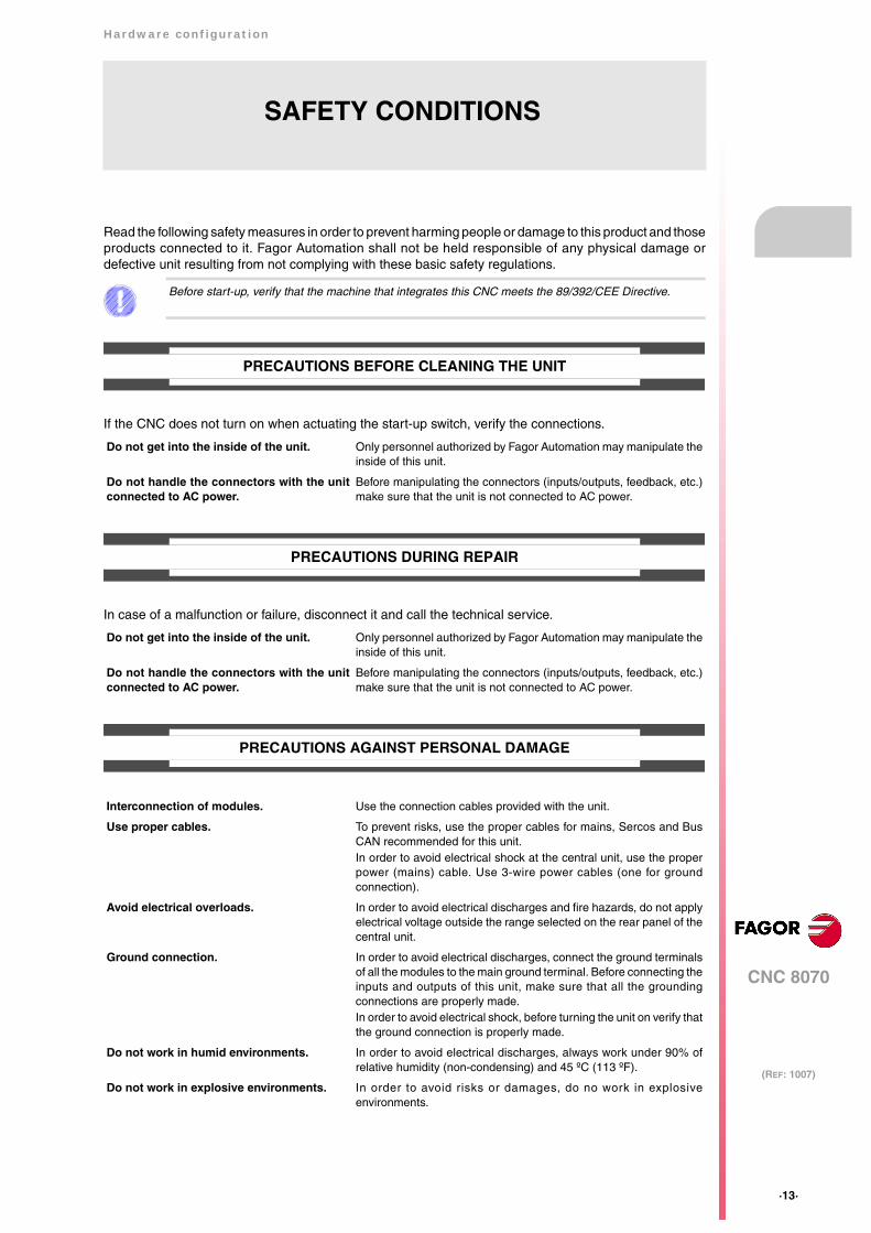
Read the following safety measures in order to prevent harming people or damage to this product and thoseproducts connected to it. Fagor Automation shall not be held responsible of any physical damage ordefective unit resulting from not complying with these basic safety regulations.
PRECAUTIONS BEFORE CLEANING THE UNIT
If the CNC does not turn on when actuating the start-up switch, verify the connections.
PRECAUTIONS DURING REPAIR
In case of a malfunction or failure, disconnect it and call the technical service.
PRECAUTIONS AGAINST PERSONAL DAMAGE
Before start-up, verify that the machine that integrates this CNC meets the 89/392/CEE Directive.
Do not get into the inside of the unit. Only personnel authorized by Fagor Automation may manipulate theinside of this unit.
Do not handle the connectors with the unitconnected to AC power.
Before manipulating the connectors (inputs/outputs, feedback, etc.)make sure that the unit is not connected to AC power.
Interconnection of modules. Use the connection cables provided with the unit.
Use proper cables. To prevent risks, use the proper cables for mains, Sercos and BusCAN recommended for this unit. In order to avoid electrical shock at the central unit, use the properpower (mains) cable. Use 3-wire power cables (one for groundconnection).
Avoid electrical overloads. In order to avoid electrical discharges and fire hazards, do not applyelectrical voltage outside the range selected on the rear panel of thecentral unit.
Ground connection. In order to avoid electrical discharges, connect the ground terminalsof all the modules to the main ground terminal. Before connecting theinputs and outputs of this unit, make sure that all the groundingconnections are properly made.In order to avoid electrical shock, before turning the unit on verify thatthe ground connection is properly made.
Do not work in humid environments. In order to avoid electrical discharges, always work under 90% ofrelative humidity (non-condensing) and 45 ºC (113 ºF).
Do not work in explosive environments. In order to avoid risks or damages, do no work in explosiveenvironments.
·14·
Hardware configuration
CNC 8070
(REF: 1007)
PRECAUTIONS AGAINST PRODUCT DAMAGE
PROTECTIONS OF THE UNIT ITSELF
Working environment. This unit is ready to be used in industrial environments complying withthe directives and regulations effective in the European Community.Fagor Automation shall not be held responsible for any damagesuffered or caused by the CNC when installed in other environments(residential or homes).
Install the unit in the right place. It is recommended, whenever possible, to install the CNC away fromcoolants, chemical product, blows, etc. that could damage it.This unit complies with the European directives on electromagneticcompatibility. Nevertheless, it is recommended to keep it away fromsources of electromagnetic disturbance such as:
Powerful loads connected to the same AC power line as thisequipment.Nearby portable transmitters (Radio-telephones, Ham radiotransmitters).Nearby radio/TV transmitters.Nearby arc welding machines.Nearby High Voltage power lines.
Enclosures. The manufacturer is responsible of assuring that the enclosureinvolving the equipment meets all the currently effective directives ofthe European Community.
Avoid disturbances coming from themachine.
The machine must have all the interference generating elements(relay coils, contactors, motors, etc.) uncoupled.
Use the proper power supply. Use an external regulated 24 Vdc power supply for the keyboard andthe remote modules.
Grounding of the power supply. The zero volt point of the external power supply must be connectedto the main ground point of the machine.
Analog inputs and outputs connection. Use shielded cables connecting all their meshes to the correspondingpin.
Ambient conditions. The storage temperature must be between +5 ºC and +45 ºC (41 ºFand 113 ºF).The storage temperature must be between -25 ºC and 70 ºC (-13 ºFand 158 ºF).
Central unit enclosure. Make sure that the needed gap is kept between the central unit andeach wall of the enclosure.Use a DC fan to improve enclosure ventilation.
Main AC power switch. This switch must be easy to access and at a distance between 0.7 and1.7 m (2.3 and 5.6 ft) off the floor.
Remote modules. All the digital inputs and outputs have galvanic isolation viaoptocouplers between the CNC circuitry and the outside.
Hardware configuration
CNC 8070
(REF: 1007)
·15·
SAFETY SYMBOLS
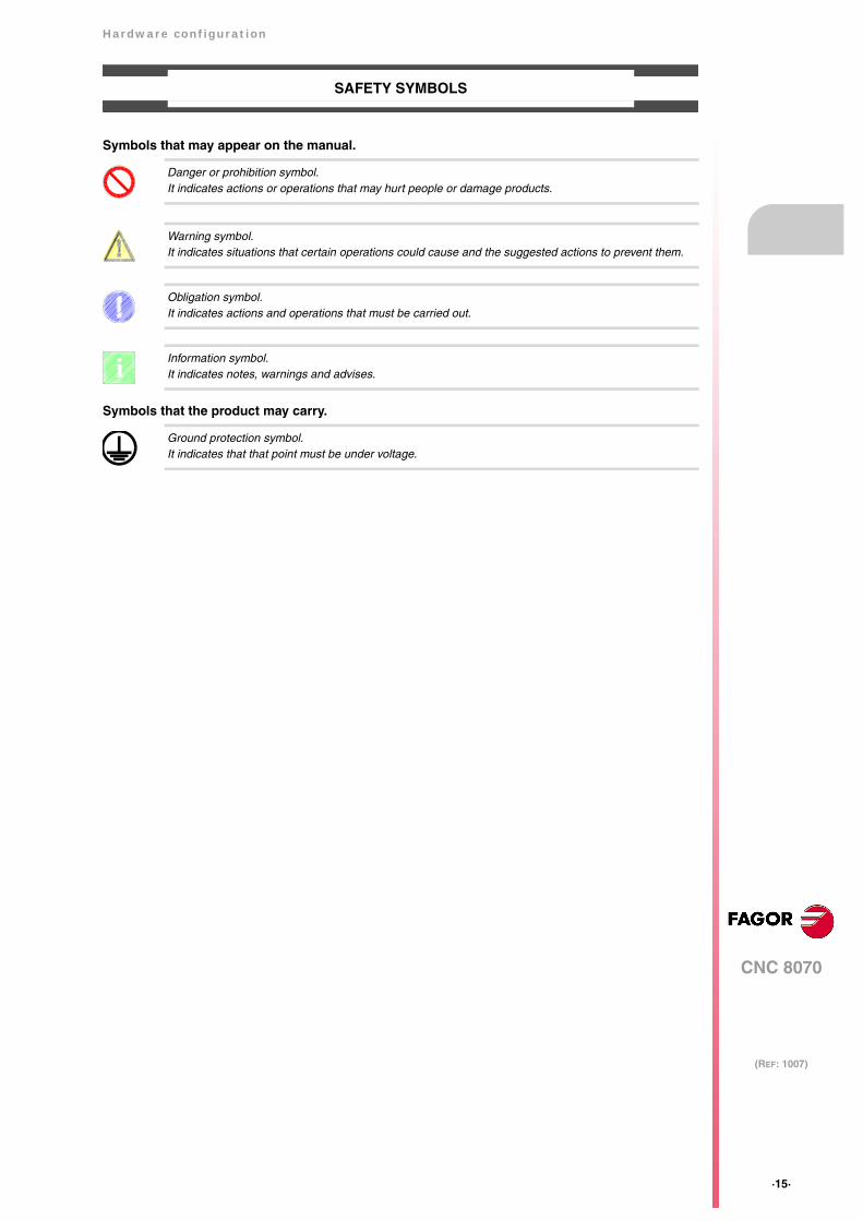
Symbols that may appear on the manual.
Symbols that the product may carry.
Danger or prohibition symbol.It indicates actions or operations that may hurt people or damage products.
Warning symbol.It indicates situations that certain operations could cause and the suggested actions to prevent them.
Obligation symbol. It indicates actions and operations that must be carried out.
Information symbol.It indicates notes, warnings and advises.
Ground protection symbol.It indicates that that point must be under voltage.
i


Hardware configuration
CNC 8070
(REF: 1007)
·17·
WARRANTY TERMS
INITIAL WARRANTY
All products manufactured or marketed by FAGOR carry a 12-month warranty for the end user which couldbe controlled by the our service network by means of the warranty control system established by FAGORfor this purpose.
In order to prevent the possibility of having the time period from the time a product leaves our warehouseuntil the end user actually receives it run against this 12-month warranty, FAGOR has set up a warrantycontrol system based on having the manufacturer or agent inform FAGOR of the destination, identificationand on-machine installation date, by filling out the document accompanying each FAGOR product in thewarranty envelope. This system, besides assuring a full year of warranty to the end user, enables our servicenetwork to know about FAGOR equipment coming from other countries into their area of responsibility.
The warranty starting date will be the one appearing as the installation date on the above mentioneddocument. FAGOR offers the manufacturer or agent 12 months to sell and install the product. This meansthat the warranty starting date may be up to one year after the product has left our warehouse so long asthe warranty control sheet has been sent back to us. This translates into the extension of warranty periodto two years since the product left our warehouse. If this sheet has not been sent to us, the warranty periodends 15 months from when the product left our warehouse.
This warranty covers all costs of material and labour involved in repairs at FAGOR carried out to correctmalfunctions in the equipment. FAGOR undertakes to repair or replace their products within the period fromthe moment manufacture begins until 8 years after the date on which it disappears from the catalogue.
It is entirely up to FAGOR to determine whether the repair is or not under warranty.
EXCLUDING CLAUSES
Repairs will be carried out on our premises. Therefore, all expenses incurred as a result of trips made bytechnical personnel to carry out equipment repairs, despite these being within the above-mentioned periodof warranty, are not covered by the warranty.
Said warranty will be applied whenever the equipment has been installed in accordance with instructions,has not be mistreated, has not been damaged by accident or by negligence and has not been tamperedwith by personnel not authorised by FAGOR. If, once servicing or repairs have been made, the cause ofthe malfunction cannot be attributed to said elements, the customer is obliged to cover the expensesincurred, in accordance with the tariffs in force.
Other warranties, implicit or explicit, are not covered and FAGOR AUTOMATION cannot be held responsiblefor other damages which may occur.
·18·
Hardware configuration
CNC 8070
(REF: 1007)
WARRANTY ON REPAIRS
In a similar way to the initial warranty, FAGOR offers a warranty on standard repairs according to thefollowing conditions:
When the customer does not choose the standard repair and just the faulty material has been replaced,the warranty will cover just the replaced parts or components within 12 months.
For sold parts the warranty is 12 moths length.
SERVICE CONTRACTS
The SERVICE CONTRACT is available for the distributor or manufacturer who buys and installs our CNCsystems.
PERIOD 12 months.
CONCEPT Covers parts and labor for repairs (or replacements) at thenetwork's own facilities.
EXCLUDING CLAUSES The same as those applied regarding the chapter on initialwarranty. If the repair is carried out within the warranty period, thewarranty extension has no effect.

Hardware configuration
CNC 8070
(REF: 1007)
·19·
MATERIAL RETURNING TERMS
When sending the central nit or the remote modules, pack them in its original package and packagingmaterial. If the original packaging material is not available, pack it as follows:
1 Get a cardboard box whose three inside dimensions are at least 15 cm (6 inches) larger than thoseof the unit. The cardboard being used to make the box must have a resistance of 170 Kg (375 lb.).
2 Attach a label indicating the owner of the unit, person to contact, type of unit and serial number. In caseof malfunction also indicate symptom and a brief description of the problem.
3 Wrap the unit in a polyethylene roll or similar material to protect it. When sending a central unit withmonitor, protect especially the screen.
4 Pad the unit inside the cardboard box with poly-utherane foam on all sides.
5 Seal the cardboard box with packing tape or industrial staples.

Hardware configuration
CNC 8070
(REF: 1007)
·21·
CNC MAINTENANCE
CLEANING
The accumulated dirt inside the unit may act as a screen preventing the proper dissipation of the heatgenerated by the internal circuitry which could result in a harmful overheating of the unit and, consequently,possible malfunctions. Accumulated dirt can sometimes act as an electrical conductor and short-circuit theinternal circuitry, especially under high humidity conditions.
To clean the operator panel and the monitor, a smooth cloth should be used which has been dipped intode-ionized water and /or non abrasive dish-washer soap (liquid, never powder) or 75º alcohol. Do not usehighly compressed air to clean the unit because it could generate electrostatic discharges.
The plastics used on the front panel are resistant to grease and mineral oils, bases and bleach, dissolveddetergents and alcohol. Avoid the action of solvents such as chlorine hydrocarbons, venzole, esters andether which can damage the plastics used to make the unit’s front panel.
PRECAUTIONS BEFORE CLEANING THE UNIT
Fagor Automation shall not be held responsible for any material or physical damage derived from theviolation of these basic safety requirements.
• Do not handle the connectors with the unit connected to AC power. Before handling these connectors(I/O, feedback, etc.), make sure that the unit is not connected to main AC power.
• Do not get into the inside of the unit. Only personnel authorized by Fagor Automation may manipulatethe inside of this unit.
• If the CNC does not turn on when actuating the start-up switch, verify the connections.

Hardware configuration
CNC 8070
(REF: 1007)
·23·
RELATED DOCUMENTATION
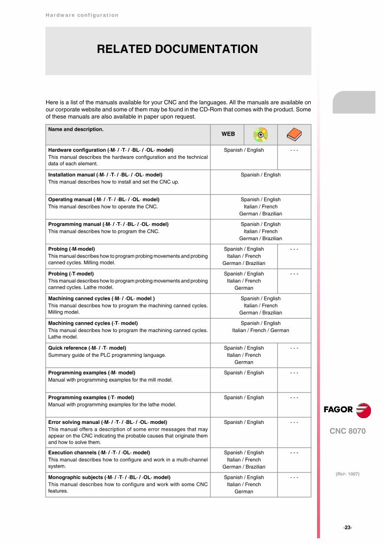
Here is a list of the manuals available for your CNC and the languages. All the manuals are available onour corporate website and some of them may be found in the CD-Rom that comes with the product. Someof these manuals are also available in paper upon request.
Name and description.
Hardware configuration (·M· / ·T· / ·BL· / ·OL· model)This manual describes the hardware configuration and the technicaldata of each element.
Spanish / English - - -
Installation manual (·M· / ·T· / ·BL· / ·OL· model)This manual describes how to install and set the CNC up.
Spanish / English
Operating manual (·M· / ·T· / ·BL· / ·OL· model)This manual describes how to operate the CNC.
Spanish / EnglishItalian / French
German / Brazilian
Programming manual (·M· / ·T· / ·BL· / ·OL· model)This manual describes how to program the CNC.
Spanish / EnglishItalian / French
German / Brazilian
Probing (·M·model)This manual describes how to program probing movements and probingcanned cycles. Milling model.
Spanish / EnglishItalian / French
German / Brazilian
- - -
Probing (·T·model)This manual describes how to program probing movements and probingcanned cycles. Lathe model.
Spanish / EnglishItalian / French
German
- - -
Machining canned cycles (·M· / ·OL· model )This manual describes how to program the machining canned cycles.Milling model.
Spanish / EnglishItalian / French
German / Brazilian
Machining canned cycles (·T· model)This manual describes how to program the machining canned cycles.Lathe model.
Spanish / EnglishItalian / French / German
Quick reference (·M· / ·T· model)Summary guide of the PLC programming language.
Spanish / EnglishItalian / French
German
- - -
Programming examples (·M· model)Manual with programming examples for the mill model.
Spanish / English - - -
Programming examples (·T· model)Manual with programming examples for the lathe model.
Spanish / English - - -
Error solving manual (·M· / ·T· / ·BL· / ·OL· model)This manual offers a description of some error messages that mayappear on the CNC indicating the probable causes that originate themand how to solve them.
Spanish / English - - -
Execution channels (·M· / ·T· / ·OL· model) This manual describes how to configure and work in a multi-channelsystem.
Spanish / EnglishItalian / French
German / Brazilian
- - -
Monographic subjects (·M· / ·T· / ·BL· / ·OL· model)This manual describes how to configure and work with some CNCfeatures.
Spanish / EnglishItalian / French
German
- - -
WEB


Hardware configuration
CNC 8070
1.
(REF: 1007)
·25·
PR
EV
IOU
S IN
FO
RM
AT
ION
.
1 PREVIOUS INFORMATION.
About this manual.
This manual describes the characteristics, technical data and connections of the hardwareassociated with the CNC. The installation manual describes the CNC configuration, machineadaptation and start-up. The installation CD that comes with the unit has the necessarydocumentation to install, set up and operate the unit.
Installation and startup.
The hardware described in this manual is ready to be used in industrial environmentscomplying with the directives and regulations effective in the European Community. Beforestart-up, verify that the machine that integrates this CNC meets the 89/392/CEE directive.
Safety conditions.
In order to avoid personal injuries and damage to this product or to those connected to it,read carefully the section on safety conditions in the introduction to this manual. FagorAutomation shall not be held responsible of any physical damage or defective unit resultingfrom not complying with these basic safety regulations.
Do not handle the connectors with the unit connected to AC power. Before doing it, make sure thatthe unit is unplugged from the power outlet.
Do not get into the inside of the unit. This unit MUST NOT be opened by unauthorized personnel. Onlypersonnel authorized by Fagor Automation may manipulate the inside of this unit.

·26·
Hardware configuration
CNC 8070
2.
(REF: 1007)
HA
RD
WA
RE
ST
RU
CT
UR
E.
2 HARDWARE STRUCTURE.
Central unit, monitor, keyboard and operator panel.
The central unit MCU is designed to be installed in the cabinet, it is not coupled to any monitor.The central unit ICU is located on the rear of the monitor. Both units have a VGA output toconnect the passive monitor LCD15SVGA or an off-the-shelf monitor.
Depending on the CNC model, it may have either a keyboard module and an operator panelmodule or a module that combines both. There is also a CNC model that has the keyboardand the operator panel into the monitor.
identification. Description.
MCU MCU central unit.
LCD10 ICU central unit. 10" LCD monitor.
LCD15 ICU central unit. 15" LCD monitor.
LCD10K ICU central unit. 10" LCD monitor with integrated keyboard andoperator panel.
OP-PANEL-HE Keyboard with integrated operator panel. Availableeither with an electronic handwheel (OP-Panel-H)or with an emergency stop button (OP-Panel-E).
KB-PANEL-H Keyboard.
JOG-PANEL Operator panel.

Hardware configuration
CNC 8070
2.
(REF: 1007)
·27·
HA
RD
WA
RE
ST
RU
CT
UR
E.
Passive screen.
The passive screen may be used to display the video signal coming from the ·VGA· connectorof the central unit and also interact with the central unit using softkeys. This screen may bethe only one connected to the central unit (for example, with the central unit MCU) or it maybe a second monitor (for example, with the central unit ICU). When the screen is used asa second monitor, both monitors show the same video signal.
Remote modules.
Remote modules may be used to have an additional number of digital and analog inputs andoutputs (remote I/O) that, distributed at different points of the machine or mounted in thecabinet, permit controlling various devices of the machine. The remote modules aredistributed by groups (nodes) and are connected to the central unit through the CAN busthat can have up to 32 nodes, including the central unit and the keyboards.
The CNC has remote modules for CANfagor bus (RIO70 series) and for CANopen bus(series RIO5 and RIOW) When the CNC works with CANopen bus, this bus lets combinein the bus groups (nodes) formed by RIO5 and RIOW series modules; modules of both seriescannot be combined in the same group.
identification. Description.
LCD15SVGA 15" LCD passive monitor.
identification. Description.
RIO5 Remote modules (CANopen protocol).• Digital inputs and outputs.• General purpose analog inputs and outputs.• Analog inputs for PT100 temperature sensors.
RIOW Remote modules (CANopen protocol).• Digital inputs and outputs.• General purpose analog inputs and outputs.• Analog inputs for PT100 temperature sensors.
RIO70 Remote modules (CANfagor protocol).• Digital inputs and outputs.• General purpose analog inputs and outputs.• Feedback inputs.
DIGITAL IN/OUT
X5
X6
X7
X8
I13
I24
I1
I12
GNDO16
O9+24V
GNDO8
O1+24V
X1
X2
X3
X4
I13
I24
I1
I12
GNDO16
O9+24V
GNDO8
O1+24V
GND
LSH
SH
HX3
GNDLSH
SH
HX2
CAN
POWERANALOG I/O
ERR
RUN
X1
CHS
GND
+24V
4
01FE
DCBA98 7 6 5 32
ADDRESS
SPEED10
LT
10
X4
O1+O1-SH
X5
RL1R1+R1-RF1SH
X6
+12I1+
I1-SH
-12GND
STOP
RUN
TX
RX
I/O
Overflow
56
78
12
34
ON
24V 24V 0V 0V 4 8
1 5
2 6
3 7
CA
DB
4 8
1 5
2 6
3 7
CA
DB
4 8
1 5
2 6
3 7
CA
DB
4 8
1 5
2 6
3 7
CA
DB
DIGITAL INPUT
X1
X2
GNDI8
I1N.C.
I2I3I4I5I6I7
GNDI16
I9N.C.
I10I11I12
I13I14I15
DIGITAL OUTPUT
X1
X2
GNDO8
O1+24V
O2O3O4O5O6O7
GNDO16
O9+24V.
O10O11O12O13O14O15
COUNTER
X1
X2
X3
X4
X5
GNDCAN L
SHIELD
SHIELDCAN H
X3
GNDCAN L
SHIELD
SHIELDCAN H
X2
POWER SUPPLY
4
01FEDCBA98 7 6 5 32
ADD MSBLINE TERM
10
12
ADDRESS
RESET
POWER
SYSTEM READY
+5 ERROR
+5 OVER CURRENT
OVER VOLTAGE+5V
X1
GND INCHASIS
GND IN+24V IN
SYSTEMREADY
·28·
Hardware configuration
CNC 8070
2.
(REF: 1007)
HA
RD
WA
RE
ST
RU
CT
UR
E.
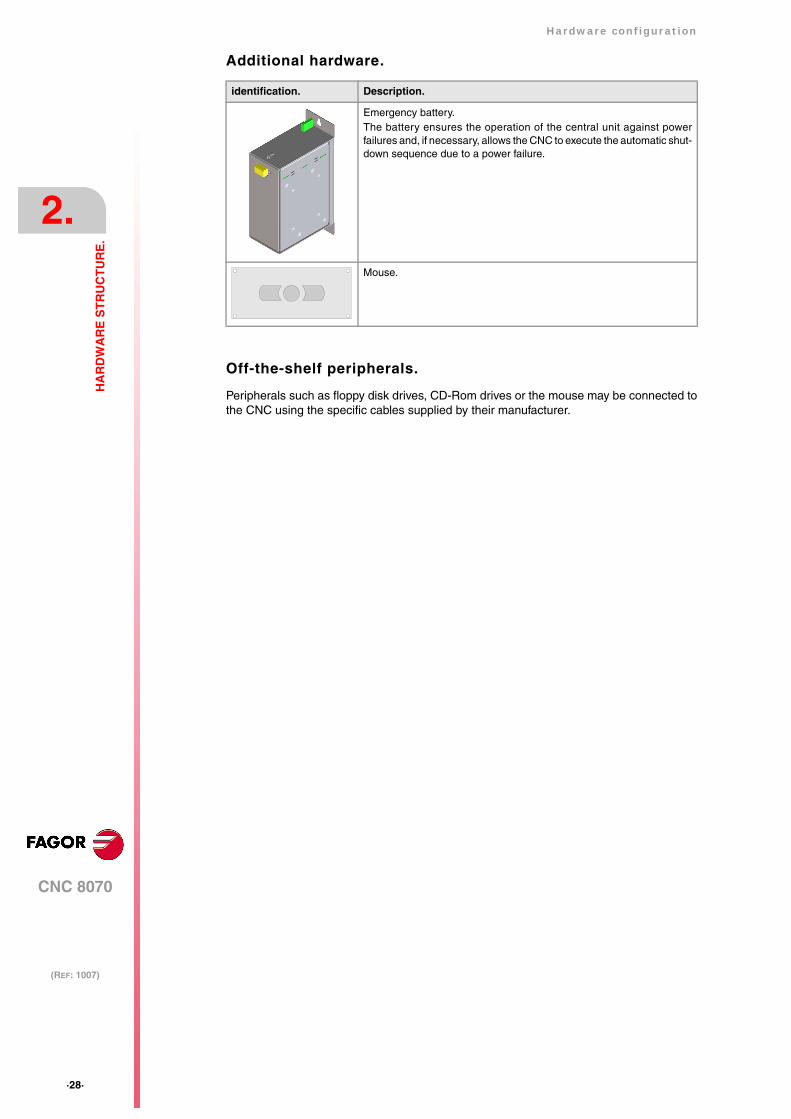
Additional hardware.
Off-the-shelf peripherals.
Peripherals such as floppy disk drives, CD-Rom drives or the mouse may be connected tothe CNC using the specific cables supplied by their manufacturer.
identification. Description.
Emergency battery. The battery ensures the operation of the central unit against powerfailures and, if necessary, allows the CNC to execute the automatic shut-down sequence due to a power failure.
Mouse.
Hardware configuration
CNC 8070
2.
(REF: 1007)
·29·
HA
RD
WA
RE
ST
RU
CT
UR
E.
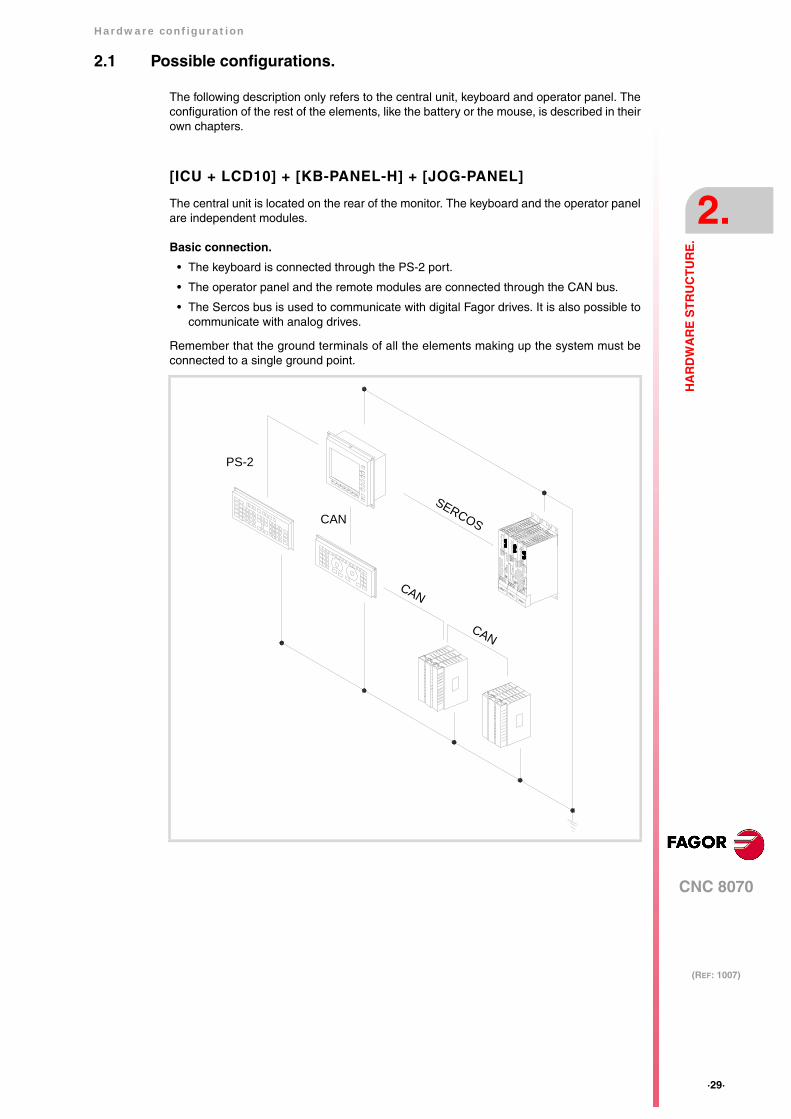
2.1 Possible configurations.
The following description only refers to the central unit, keyboard and operator panel. Theconfiguration of the rest of the elements, like the battery or the mouse, is described in theirown chapters.
[ICU + LCD10] + [KB-PANEL-H] + [JOG-PANEL]
The central unit is located on the rear of the monitor. The keyboard and the operator panelare independent modules.
Basic connection.
• The keyboard is connected through the PS-2 port.
• The operator panel and the remote modules are connected through the CAN bus.
• The Sercos bus is used to communicate with digital Fagor drives. It is also possible tocommunicate with analog drives.
Remember that the ground terminals of all the elements making up the system must beconnected to a single ground point.
CAN
SERCOS
CAN
CAN
PS-2
·30·
Hardware configuration
CNC 8070
2.
(REF: 1007)
HA
RD
WA
RE
ST
RU
CT
UR
E.
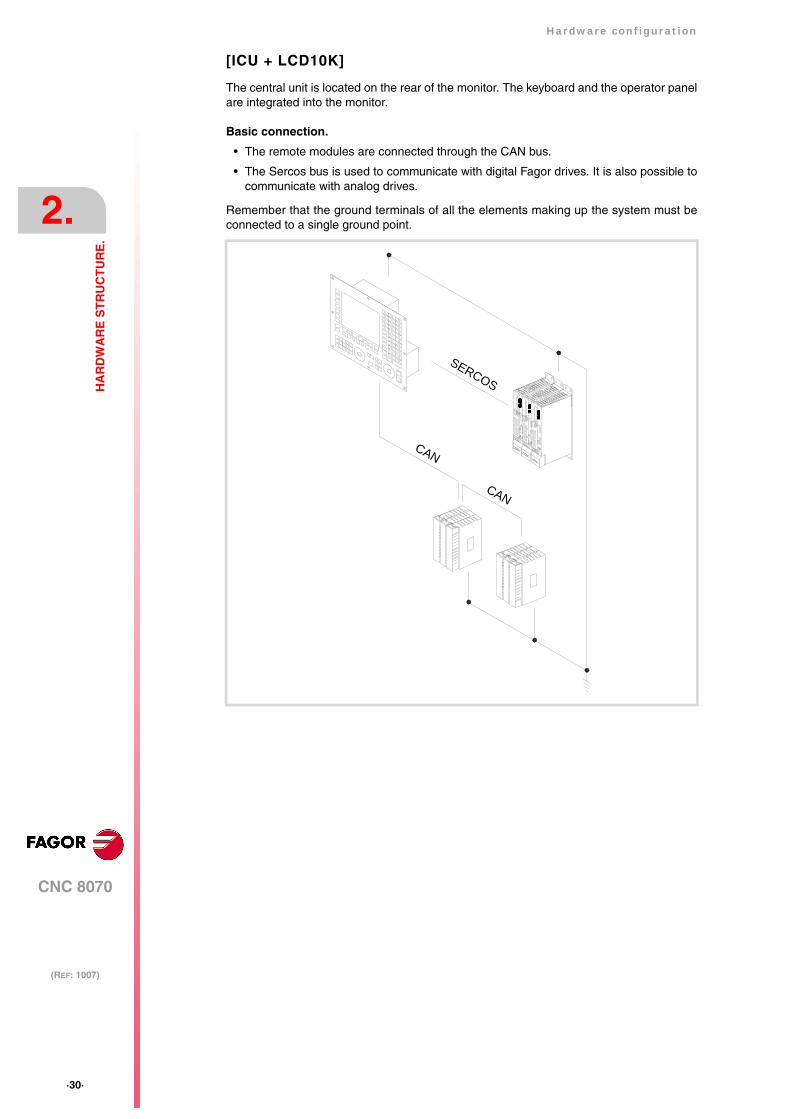
[ICU + LCD10K]
The central unit is located on the rear of the monitor. The keyboard and the operator panelare integrated into the monitor.
Basic connection.
• The remote modules are connected through the CAN bus.
• The Sercos bus is used to communicate with digital Fagor drives. It is also possible tocommunicate with analog drives.
Remember that the ground terminals of all the elements making up the system must beconnected to a single ground point.
SERCOS
CAN
CAN
Hardware configuration
CNC 8070
2.
(REF: 1007)
·31·
HA
RD
WA
RE
ST
RU
CT
UR
E.
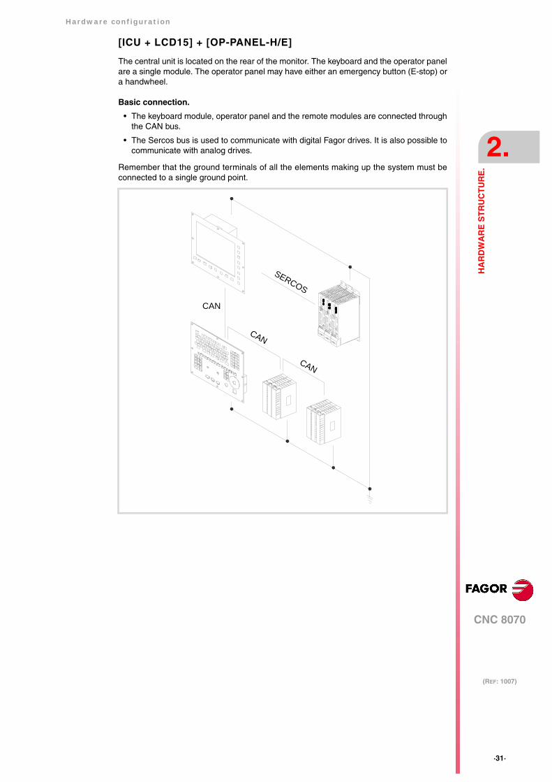
[ICU + LCD15] + [OP-PANEL-H/E]
The central unit is located on the rear of the monitor. The keyboard and the operator panelare a single module. The operator panel may have either an emergency button (E-stop) ora handwheel.
Basic connection.
• The keyboard module, operator panel and the remote modules are connected throughthe CAN bus.
• The Sercos bus is used to communicate with digital Fagor drives. It is also possible tocommunicate with analog drives.
Remember that the ground terminals of all the elements making up the system must beconnected to a single ground point.
SERCOS
CAN
CAN
CAN
·32·
Hardware configuration
CNC 8070
2.
(REF: 1007)
HA
RD
WA
RE
ST
RU
CT
UR
E.
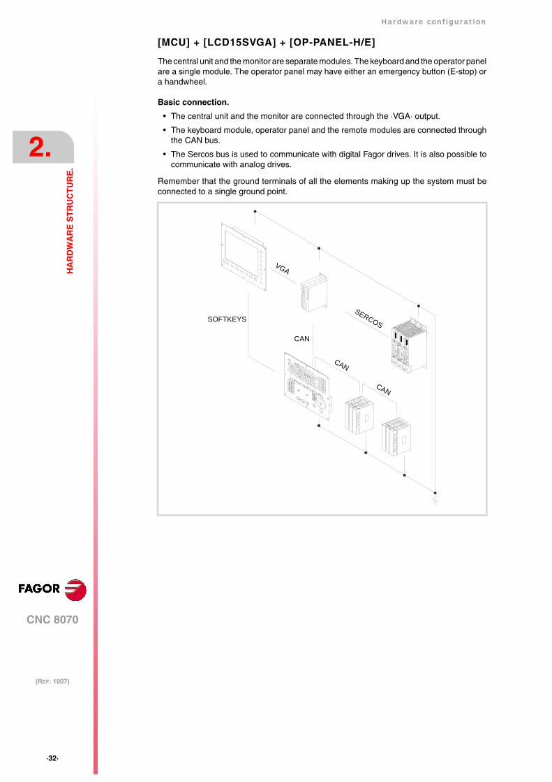
[MCU] + [LCD15SVGA] + [OP-PANEL-H/E]
The central unit and the monitor are separate modules. The keyboard and the operator panelare a single module. The operator panel may have either an emergency button (E-stop) ora handwheel.
Basic connection.
• The central unit and the monitor are connected through the ·VGA· output.
• The keyboard module, operator panel and the remote modules are connected throughthe CAN bus.
• The Sercos bus is used to communicate with digital Fagor drives. It is also possible tocommunicate with analog drives.
Remember that the ground terminals of all the elements making up the system must beconnected to a single ground point.
CAN
SERCOS
CAN
CAN
VGA
SOFTKEYS
Hardware configuration
CNC 8070
3.
(REF: 1007)
·33·
HE
AT
DIS
SIP
AT
ION
. CE
NT
RA
L U
NIT
(C
PU
) E
NC
LO
SU
RE
.
3 HEAT DISSIPATION. CENTRAL UNIT (CPU) ENCLOSURE.
The working temperature of the central unit enclosure must not exceed 45 ºC (113ºF). Toensure that it does not exceed this temperature, the enclosure must meet the followingrequirements.
• The enclosure must have enough surface inside to evacuate the heat generated insideand keep the ambient conditions within the working temperature range.
• The enclosure must respect the minimum distances recommended between theenclosure walls and the central unit to let the air flow and improve heat dissipation.
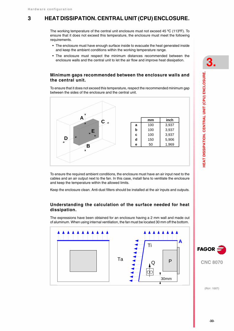
Minimum gaps recommended between the enclosure walls andthe central unit.
To ensure that it does not exceed this temperature, respect the recommended minimum gapbetween the sides of the enclosure and the central unit.
To ensure the required ambient conditions, the enclosure must have an air input next to thecables and an air output next to the fan. In this case, install fans to ventilate the enclosureand keep the temperature within the allowed limits.
Keep the enclosure clean. Anti-dust filters should be installed at the air inputs and outputs.
Understanding the calculation of the surface needed for heatdissipation.
The expressions have been obtained for an enclosure having a 2 mm wall and made outof aluminum. When using internal ventilation, the fan must be located 30 mm off the bottom.
mm incha 100 3,937b 100 3,937c 100 3,937d 150 5,906e 50 1,969
A
B
C
DE
Ti
Ta
A
P
30mm
Q
·34·
Hardware configuration
CNC 8070
3.
(REF: 1007)
HE
AT
DIS
SIP
AT
ION
. CE
NT
RA
L U
NIT
(C
PU
) E
NC
LO
SU
RE
.
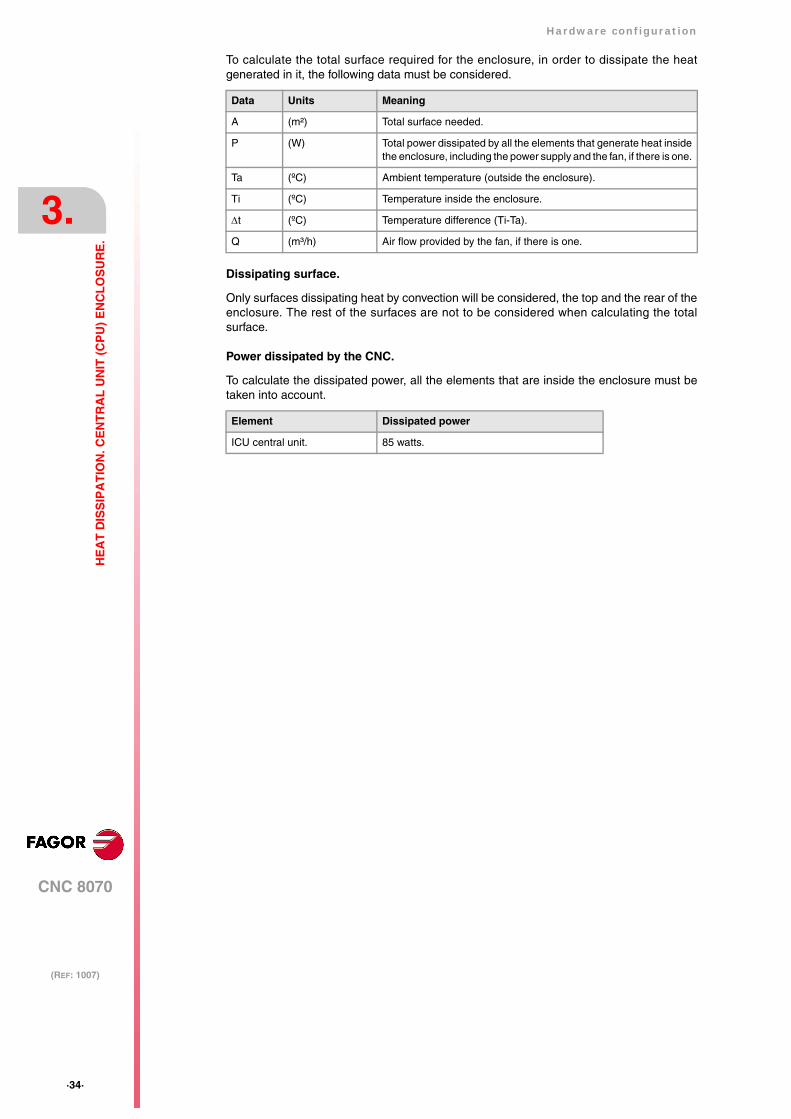
To calculate the total surface required for the enclosure, in order to dissipate the heatgenerated in it, the following data must be considered.
Dissipating surface.
Only surfaces dissipating heat by convection will be considered, the top and the rear of theenclosure. The rest of the surfaces are not to be considered when calculating the totalsurface.
Power dissipated by the CNC.
To calculate the dissipated power, all the elements that are inside the enclosure must betaken into account.
Data Units Meaning
A (m²) Total surface needed.
P (W) Total power dissipated by all the elements that generate heat insidethe enclosure, including the power supply and the fan, if there is one.
Ta (ºC) Ambient temperature (outside the enclosure).
Ti (ºC) Temperature inside the enclosure.
∆t (ºC) Temperature difference (Ti-Ta).
Q (m³/h) Air flow provided by the fan, if there is one.
Element Dissipated power
ICU central unit. 85 watts.
Hardware configuration
CNC 8070
3.
(REF: 1007)
·35·
HE
AT
DIS
SIP
AT
ION
. CE
NT
RA
L U
NIT
(C
PU
) E
NC
LO
SU
RE
.
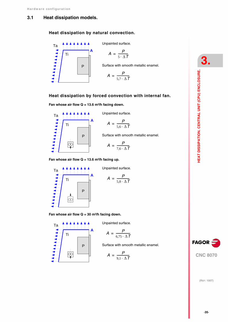
3.1 Heat dissipation models.
Heat dissipation by natural convection.
Heat dissipation by forced convection with internal fan.
Fan whose air flow Q = 13.6 m³/h facing down.
Fan whose air flow Q = 13.6 m³/h facing up.
Fan whose air flow Q = 30 m³/h facing down.
Unpainted surface.
Surface with smooth metallic enamel.
A P5 ∆T⋅--------------=
A P5,7 ∆T⋅------------------=
Ti
TaA
P
Unpainted surface.
Surface with smooth metallic enamel.
A P5,6 ∆T⋅------------------=
A P7,6 ∆T⋅------------------=
Ti
TaA
P
Unpainted surface.
A P5,8 ∆T⋅------------------=Ti
TaA
P
Unpainted surface.
Surface with smooth metallic enamel.
A P6,75 ∆T⋅--------------------=
A P9,1 ∆T⋅------------------=
Ti
TaA
P
·36·
Hardware configuration
CNC 8070
3.
(REF: 1007)
HE
AT
DIS
SIP
AT
ION
. CE
NT
RA
L U
NIT
(C
PU
) E
NC
LO
SU
RE
.
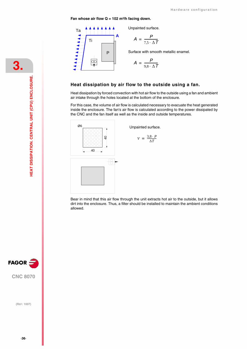
Fan whose air flow Q = 102 m³/h facing down.
Heat dissipation by air flow to the outside using a fan.
Heat dissipation by forced convection with hot air flow to the outside using a fan and ambientair intake through the holes located at the bottom of the enclosure.
For this case, the volume of air flow is calculated necessary to evacuate the heat generatedinside the enclosure. The fan's air flow is calculated according to the power dissipated bythe CNC and the fan itself as well as the inside and outside temperatures.
Bear in mind that this air flow through the unit extracts hot air to the outside, but it allowsdirt into the enclosure. Thus, a filter should be installed to maintain the ambient conditionsallowed.
Unpainted surface.
Surface with smooth metallic enamel.
A P7,5 ∆T⋅------------------=
A P9,8 ∆T⋅------------------=
Ti
TaA
P
Unpainted surface.
V 3,8 P⋅∆T
---------------=
40
40
Ø6
Hardware configuration
CNC 8070
4.
(REF: 1007)
·37·
CE
NT
RA
L U
NIT
S IC
U -
MC
U.
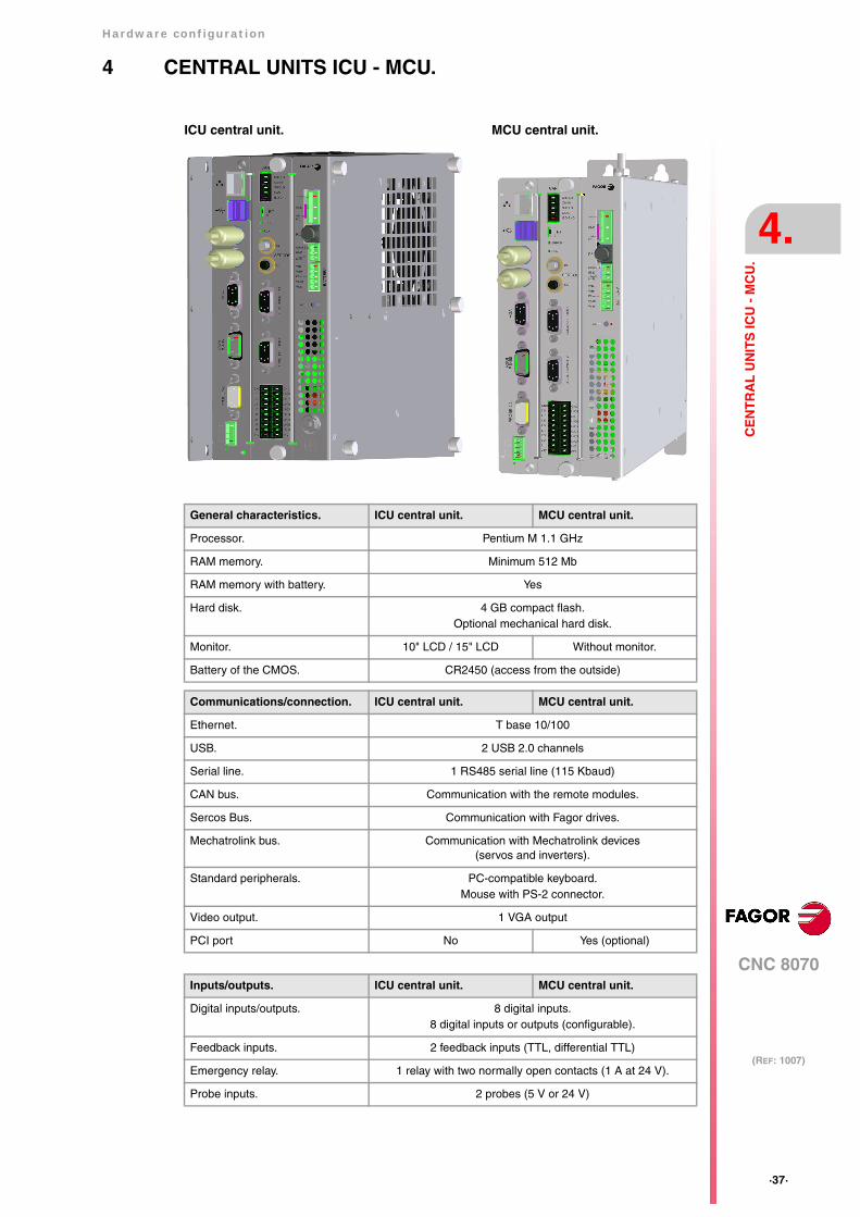
4 CENTRAL UNITS ICU - MCU.
ICU central unit. MCU central unit.
General characteristics. ICU central unit. MCU central unit.
Processor. Pentium M 1.1 GHz
RAM memory. Minimum 512 Mb
RAM memory with battery. Yes
Hard disk. 4 GB compact flash.Optional mechanical hard disk.
Monitor. 10" LCD / 15" LCD Without monitor.
Battery of the CMOS. CR2450 (access from the outside)
Communications/connection. ICU central unit. MCU central unit.
Ethernet. T base 10/100
USB. 2 USB 2.0 channels
Serial line. 1 RS485 serial line (115 Kbaud)
CAN bus. Communication with the remote modules.
Sercos Bus. Communication with Fagor drives.
Mechatrolink bus. Communication with Mechatrolink devices(servos and inverters).
Standard peripherals. PC-compatible keyboard.Mouse with PS-2 connector.
Video output. 1 VGA output
PCI port No Yes (optional)
Inputs/outputs. ICU central unit. MCU central unit.
Digital inputs/outputs. 8 digital inputs.8 digital inputs or outputs (configurable).
Feedback inputs. 2 feedback inputs (TTL, differential TTL)
Emergency relay. 1 relay with two normally open contacts (1 A at 24 V).
Probe inputs. 2 probes (5 V or 24 V)
·38·
Hardware configuration
CNC 8070
4.
(REF: 1007)
CE
NT
RA
L U
NIT
S IC
U -
MC
U.
Voltage supply for the central unit.
Universal DC power supply. Use a 24 V DC ±10% 3.5 A power supply. See "4.7 Powerconnection." on page 64.
Optionally, an external battery may be connected to ensure that the unit is properly poweredoff when detecting supply voltage outages. The battery provides an autonomy of about 20minutes when it is fully charged.
Battery-powered RAM memory (non-volatile RAM).
The CNC has battery-powered RAM memory that keeps the information saved in it evenwhen a power failure occurs. The RAM memory is powered by a 3 V CR2450 battery thatmay be accessed from the outside. See "4.8 housing for the compact flash and battery-powered RAM memory." on page 65.
The RAM memory with battery always saves the position of the axes, the rest of the datathat it saves is determined by machine parameters, like for example, PLC registers(parameter BKUPREG), common arithmetic parameters (parameter BKUPCUP), etc.
Available monitors.
LCD monitors attached to the central unit ICU.
The central unit is located on the rear of the monitor and may be the following sizes.
Passive LCD monitor.
LCD monitor with softkeys that is connected to the central unit through the ·VGA· output.
Off-the-shelf VGA monitor.
An off-the-shelf VGA monitor may be connected to the ICU central unit and to the MCU, butits cable cannot exceed 10 meters.
Saving data in the battery-powered RAM required version V3.14 or higher. i
Name. Description.
LCD-10 10" LCD monitor (18-bit color). Resolution 800x600.
LCD-10K 10" LCD monitor (18-bit color) with keyboard and integrated operator panel.Resolution 800x600.
LCD-15 15" LCD monitor (18-bit color).Resolution 1024x768.
Name. Description.
LCD-15SVGA 15" LCD passive monitor (18-bit color).Resolution 1024x768.
Hardware configuration
CNC 8070
4.
(REF: 1007)
·39·
CE
NT
RA
L U
NIT
S IC
U -
MC
U.
4.1 Technical characteristics.
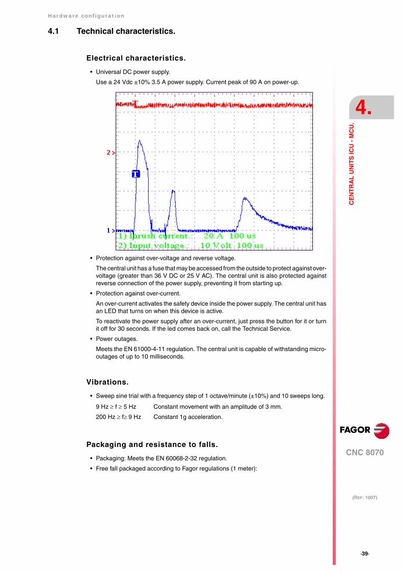
Electrical characteristics.
• Universal DC power supply.
Use a 24 Vdc ±10% 3.5 A power supply. Current peak of 90 A on power-up.
• Protection against over-voltage and reverse voltage.
The central unit has a fuse that may be accessed from the outside to protect against over-voltage (greater than 36 V DC or 25 V AC). The central unit is also protected againstreverse connection of the power supply, preventing it from starting up.
• Protection against over-current.
An over-current activates the safety device inside the power supply. The central unit hasan LED that turns on when this device is active.
To reactivate the power supply after an over-current, just press the button for it or turnit off for 30 seconds. If the led comes back on, call the Technical Service.
• Power outages.
Meets the EN 61000-4-11 regulation. The central unit is capable of withstanding micro-outages of up to 10 milliseconds.
Vibrations.
• Sweep sine trial with a frequency step of 1 octave/minute (±10%) and 10 sweeps long.
Packaging and resistance to falls.
• Packaging: Meets the EN 60068-2-32 regulation.
• Free fall packaged according to Fagor regulations (1 meter):
9 Hz ≥ f ≥ 5 Hz Constant movement with an amplitude of 3 mm.
200 Hz ≥ f≥ 9 Hz Constant 1g acceleration.

·40·
Hardware configuration
CNC 8070
4.
(REF: 1007)
CE
NT
RA
L U
NIT
S IC
U -
MC
U.
Ambient conditions.
• Relative humidity: 20-85% without condensation.
• Work temperature: 0-55 ºC with an average lower than 35 ºC.
• Storage temperature: Between -40 ºC ( 77 ºF) and +70 ºC (158 ºF).
• Maximum work altitude: Meets the IEC 1131-2 standard.
Degree of protection.
• Front panel: It meets the protection standard IP 56.
• Rear panel: It meets the protection standard IP 20.
The machine manufacturer must comply with the EN 60204-1 (IEC-204-1) regulationregarding electrical shocks in case of defective input/output pins with external power supplywhen not plugging the connector before turning the power supply on.
Do not get into the inside of the unit. This unit MUST NOT be opened by unauthorized personnel. Onlypersonnel authorized by Fagor Automation may manipulate the inside of this unit.
Hardware configuration
CNC 8070
4.
(REF: 1007)
·41·
CE
NT
RA
L U
NIT
S IC
U -
MC
U.
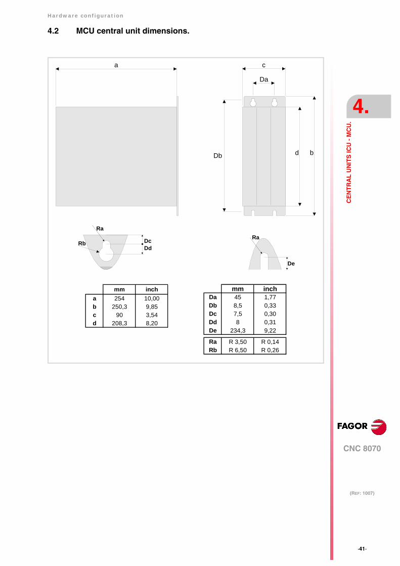
4.2 MCU central unit dimensions.
Da
c
d b
a
Db
De
Ra
Rb DcDd
Ra
mm inchDa 45 1,77Db 8,5 0,33Dc 7,5 0,30Dd 8 0,31De 234,3 9,22
Ra R 3,50 R 0,14Rb R 6,50 R 0,26
mm incha 254 10,00b 250,3 9,85c 90 3,54d 208,3 8,20
·42·
Hardware configuration
CNC 8070
4.
(REF: 1007)
CE
NT
RA
L U
NIT
S IC
U -
MC
U.
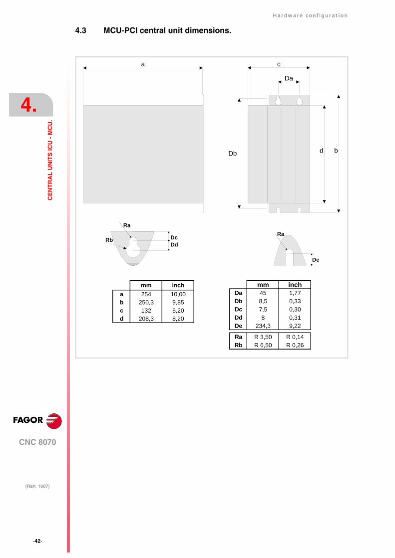
4.3 MCU-PCI central unit dimensions.
mm incha 254 10,00b 250,3 9,85c 132 5,20d 208,3 8,20
mm inchDa 45 1,77Db 8,5 0,33Dc 7,5 0,30Dd 8 0,31De 234,3 9,22
Ra R 3,50 R 0,14Rb R 6,50 R 0,26
Da
c
d b
a
Db
De
Ra
Rb DcDd
Ra
Hardware configuration
CNC 8070
4.
(REF: 1007)
·43·
CE
NT
RA
L U
NIT
S IC
U -
MC
U.
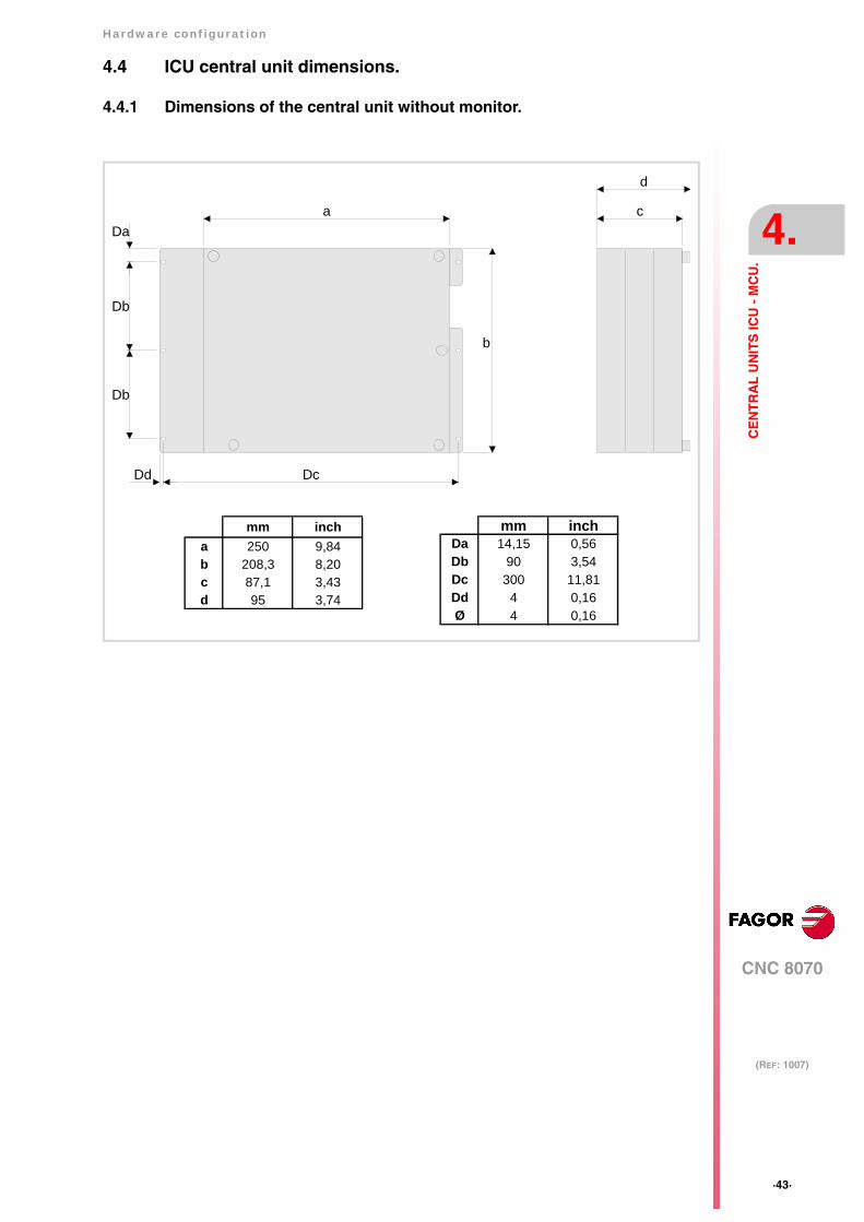
4.4 ICU central unit dimensions.
4.4.1 Dimensions of the central unit without monitor.
b
a
Db
Da
Dc
Db
c
d
Dd
mm incha 250 9,84b 208,3 8,20c 87,1 3,43d 95 3,74
mm inchDa 14,15 0,56Db 90 3,54Dc 300 11,81Dd 4 0,16Ø 4 0,16

·44·
Hardware configuration
CNC 8070
4.
(REF: 1007)
CE
NT
RA
L U
NIT
S IC
U -
MC
U.
4.4.2 Dimensions of the central unit with LCD-10 monitor.
c a
b
Da Da
Db
d
A
Ø
A
mm incha 325 12,80b 240 9,45c 111,1 4,37d 119 4,69
mm inchDa 158 6,22Db 231 9,09Dc 4,5 0,18Ø 4,5 0,18
Hardware configuration
CNC 8070
4.
(REF: 1007)
·45·
CE
NT
RA
L U
NIT
S IC
U -
MC
U.
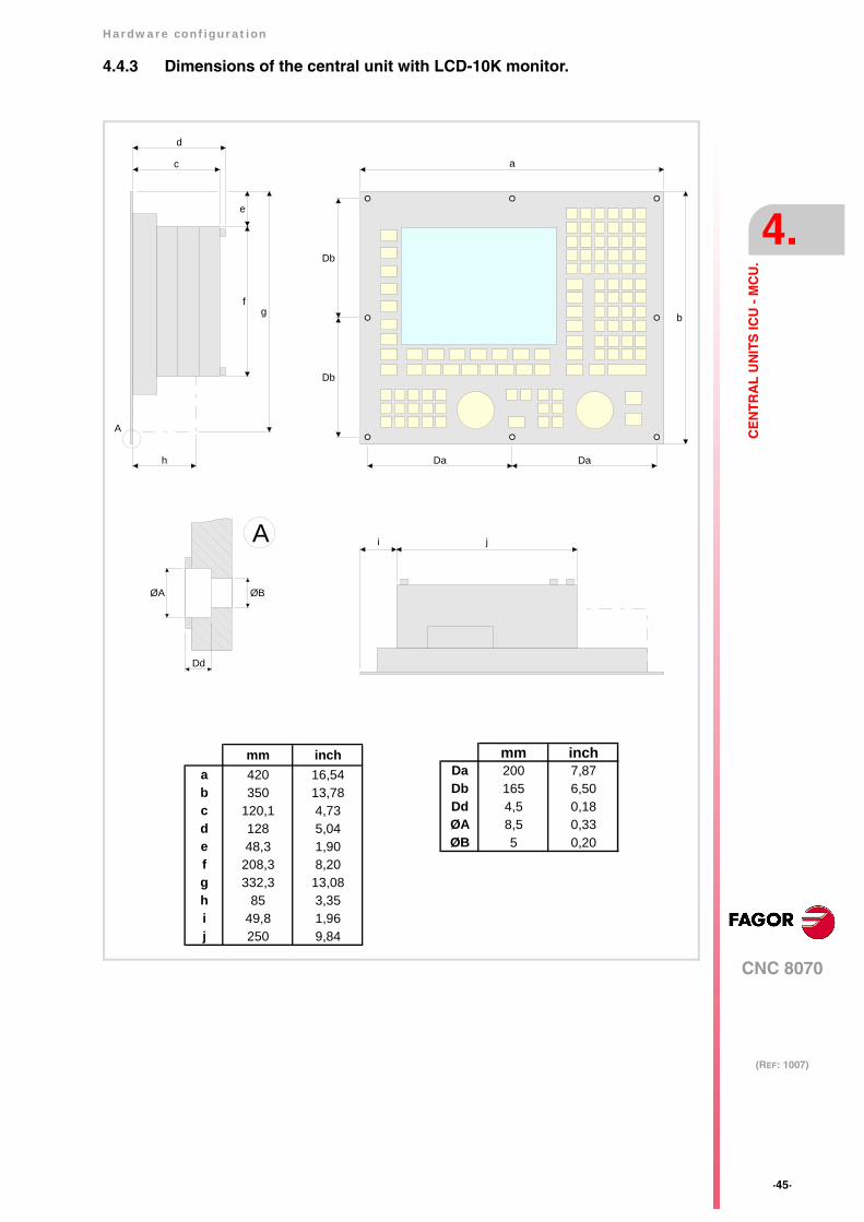
4.4.3 Dimensions of the central unit with LCD-10K monitor.
mm inchDa 200 7,87Db 165 6,50Dd 4,5 0,18ØA 8,5 0,33ØB 5 0,20
mm incha 420 16,54b 350 13,78c 120,1 4,73d 128 5,04e 48,3 1,90f 208,3 8,20g 332,3 13,08h 85 3,35i 49,8 1,96j 250 9,84
c
e
a
b
Da Da
Db
Db
ji
f
h
g
d
A
A
Dd
ØA ØB
·46·
Hardware configuration
CNC 8070
4.
(REF: 1007)
CE
NT
RA
L U
NIT
S IC
U -
MC
U.
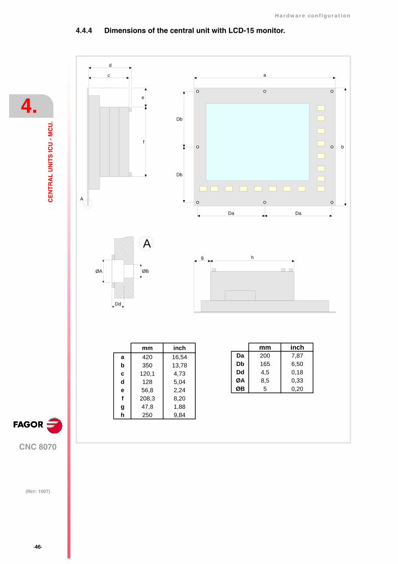
4.4.4 Dimensions of the central unit with LCD-15 monitor.
mm inchDa 200 7,87Db 165 6,50Dd 4,5 0,18ØA 8,5 0,33ØB 5 0,20
mm incha 420 16,54b 350 13,78c 120,1 4,73d 128 5,04e 56,8 2,24f 208,3 8,20g 47,8 1,88h 250 9,84
c
e
f
a
b
Da Da
Db
Db
g
d
h
A
Dd
ØA ØB
A

Hardware configuration
CNC 8070
4.
(REF: 1007)
·47·
CE
NT
RA
L U
NIT
S IC
U -
MC
U.
4.5 Dimensions and characteristics of the enclosure.
Ambient characteristics of the enclosure.
The working temperature of the central unit enclosure must not exceed 45 ºC (113ºF). Toensure that it does not exceed this temperature, the enclosure must meet the followingrequirements. See chapter "3 Heat dissipation. Central unit (cpu) enclosure.".
• The enclosure must have enough surface inside to evacuate the heat generated insideand keep the ambient conditions within the working temperature range.
• The enclosure must respect the minimum distances recommended between theenclosure walls and the central unit.
Room reserved for cables.
Reserve some room for the cables in the connector area. This space makes it possible tobend the cables for the CPU connection with the recommended bending radius. Special caremust be taken with the Sercos connection because bending the optic fiber too much couldbreak it.
Fastening the unit (ICU central unit).
The central unit must be installed in a proper enclosure that may be located on the machineor on an external support. To insert the unit into the enclosure, it must have a big enoughhole to allow to insert it easily, without obstacles and without forcing the unit.
Once the unit has been inserted into the enclosure, secure it from the outside with M4 orUNC8 screws. To properly secure it, use the mounting holes on the front panel of the unit.
Central unit with LCD-10 monitor.
Db
Da Da
W
H
mm inchDa 158 6,22Db 231 9,09
mm inchW 306 12,05H 221 8,70
·48·
Hardware configuration
CNC 8070
4.
(REF: 1007)
CE
NT
RA
L U
NIT
S IC
U -
MC
U.
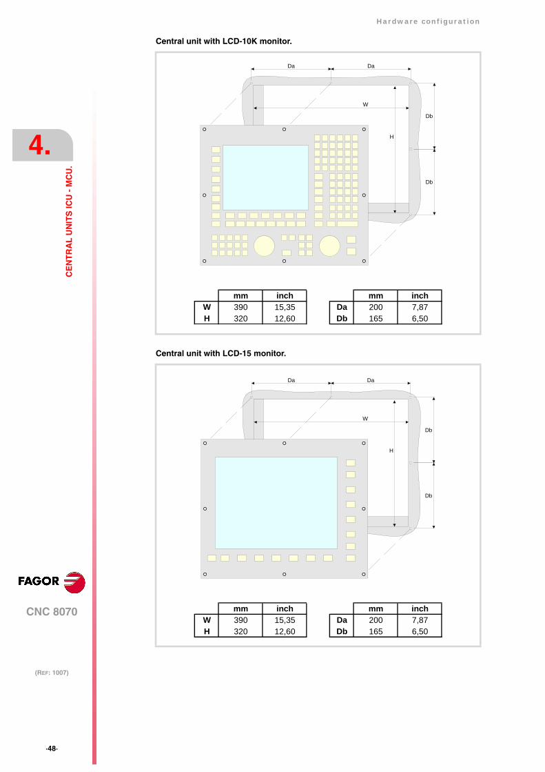
Central unit with LCD-10K monitor.
Central unit with LCD-15 monitor.
mm inchW 390 15,35H 320 12,60
mm inchDa 200 7,87Db 165 6,50
Db
Da Da
W
H
Db
Da Da
W
H
Db
Db
mm inchW 390 15,35H 320 12,60
mm inchDa 200 7,87Db 165 6,50
Hardware configuration
CNC 8070
4.
(REF: 1007)
·49·
CE
NT
RA
L U
NIT
S IC
U -
MC
U.
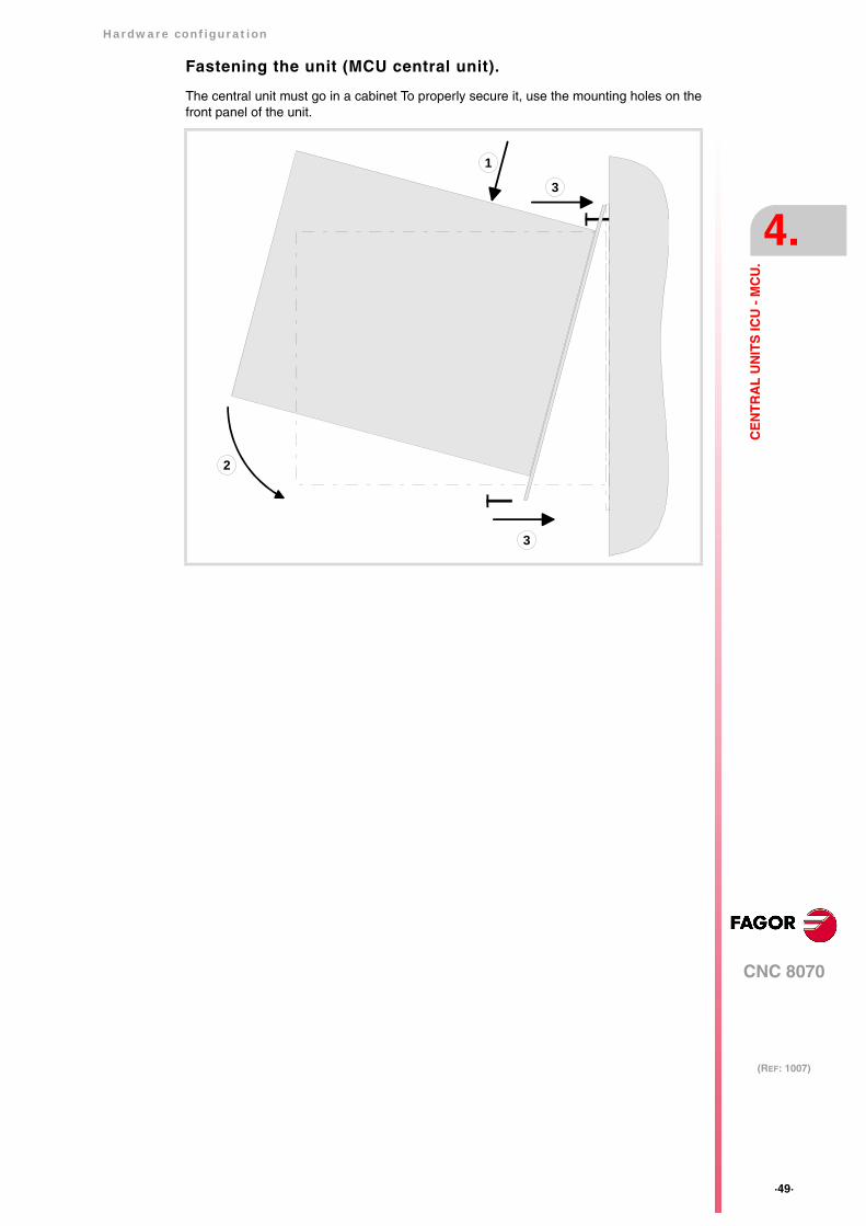
Fastening the unit (MCU central unit).
The central unit must go in a cabinet To properly secure it, use the mounting holes on thefront panel of the unit.
1
3
2
3
·50·
Hardware configuration
CNC 8070
4.
(REF: 1007)
CE
NT
RA
L U
NIT
S IC
U -
MC
U.
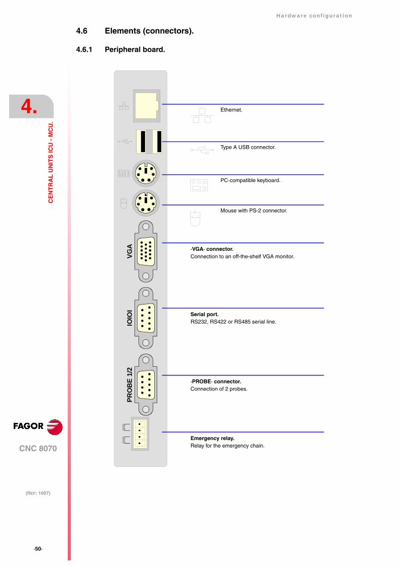
4.6 Elements (connectors).
4.6.1 Peripheral board.
VGA
IOIO
IPR
OB
E 1/
2
·VGA· connector.Connection to an off-the-shelf VGA monitor.
Emergency relay.Relay for the emergency chain.
·PROBE· connector.Connection of 2 probes.
Serial port.RS232, RS422 or RS485 serial line.
Ethernet.
Type A USB connector.
PC-compatible keyboard.
Mouse with PS-2 connector.
Hardware configuration
CNC 8070
4.
(REF: 1007)
·51·
CE
NT
RA
L U
NIT
S IC
U -
MC
U.
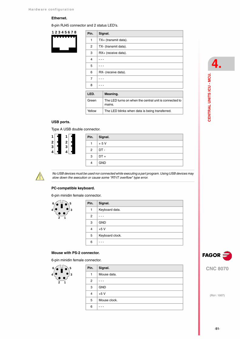
Ethernet.
8-pin RJ45 connector and 2 status LED's.
USB ports.
Type A USB double connector.
PC-compatible keyboard.
6-pin minidin female connector.
Mouse with PS-2 connector.
6-pin minidin female connector.
1 32 4 5 76 8 Pin. Signal.
1 TX+ (transmit data).
2 TX- (transmit data).
3 RX+ (receive data).
4 - - -
5 - - -
6 RX- (receive data).
7 - - -
8 - - -
LED. Meaning.
Green The LED turns on when the central unit is connected tomains.
Yellow The LED blinks when data is being transferred.
Pin. Signal.
1 + 5 V
2 DT -
3 DT +
4 GND
4
23
1
4
23
1
No USB devices must be used nor connected while executing a part program. Using USB devices mayslow down the execution or cause some "RT-IT overflow" type error.
Pin. Signal.
1 Keyboard data.
2 - - -
3 GND
4 +5 V
5 Keyboard clock.
6 - - -
1
3
5
2
4
6
Pin. Signal.
1 Mouse data.
2 - - -
3 GND
4 +5 V
5 Mouse clock.
6 - - -
1
3
5
2
4
6
·52·
Hardware configuration
CNC 8070
4.
(REF: 1007)
CE
NT
RA
L U
NIT
S IC
U -
MC
U.
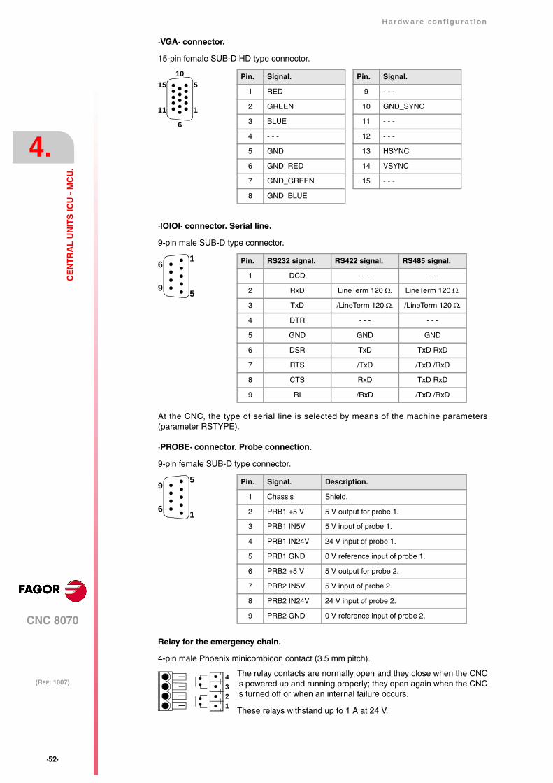
·VGA· connector.
15-pin female SUB-D HD type connector.
·IOIOI· connector. Serial line.
9-pin male SUB-D type connector.
At the CNC, the type of serial line is selected by means of the machine parameters(parameter RSTYPE).
·PROBE· connector. Probe connection.
9-pin female SUB-D type connector.
Relay for the emergency chain.
4-pin male Phoenix minicombicon contact (3.5 mm pitch).
The relay contacts are normally open and they close when the CNCis powered up and running properly; they open again when the CNCis turned off or when an internal failure occurs.
These relays withstand up to 1 A at 24 V.
Pin. Signal.
1 RED
2 GREEN
3 BLUE
4 - - -
5 GND
6 GND_RED
7 GND_GREEN
8 GND_BLUE
Pin. Signal.
9 - - -
10 GND_SYNC
11 - - -
12 - - -
13 HSYNC
14 VSYNC
15 - - -
5
1
10
6
15
11
Pin. RS232 signal. RS422 signal. RS485 signal.
1 DCD - - - - - -
2 RxD LineTerm 120 Ω. LineTerm 120 Ω.
3 TxD /LineTerm 120 Ω. /LineTerm 120 Ω.
4 DTR - - - - - -
5 GND GND GND
6 DSR TxD TxD RxD
7 RTS /TxD /TxD /RxD
8 CTS RxD TxD RxD
9 RI /RxD /TxD /RxD
1
5
6
9
Pin. Signal. Description.
1 Chassis Shield.
2 PRB1 +5 V 5 V output for probe 1.
3 PRB1 IN5V 5 V input of probe 1.
4 PRB1 IN24V 24 V input of probe 1.
5 PRB1 GND 0 V reference input of probe 1.
6 PRB2 +5 V 5 V output for probe 2.
7 PRB2 IN5V 5 V input of probe 2.
8 PRB2 IN24V 24 V input of probe 2.
9 PRB2 GND 0 V reference input of probe 2.
5
1
9
6
1234
Hardware configuration
CNC 8070
4.
(REF: 1007)
·53·
CE
NT
RA
L U
NIT
S IC
U -
MC
U.
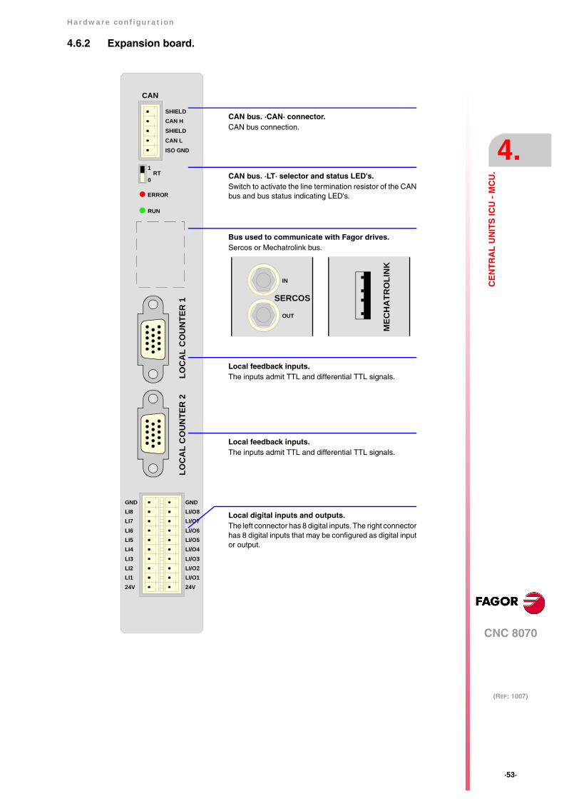
4.6.2 Expansion board.
LOC
AL
CO
UN
TER
1LO
CA
L C
OU
NTE
R 2
CAN
SHIELDCAN HSHIELDCAN LISO GND
RT1
0
ERROR
RUN
GNDLI8LI7LI6LI5LI4LI3LI2LI124V
GNDLI/O8LI/O7LI/O6LI/O5LI/O4LI/O3LI/O2LI/O124V
MEC
HA
TRO
LIN
K
SERCOS
IN
OUT
CAN bus. ·LT· selector and status LED's.Switch to activate the line termination resistor of the CANbus and bus status indicating LED's.
CAN bus. ·CAN· connector.CAN bus connection.
Local digital inputs and outputs.The left connector has 8 digital inputs. The right connectorhas 8 digital inputs that may be configured as digital inputor output.
Bus used to communicate with Fagor drives.Sercos or Mechatrolink bus.
Local feedback inputs.The inputs admit TTL and differential TTL signals.
Local feedback inputs.The inputs admit TTL and differential TTL signals.
·54·
Hardware configuration
CNC 8070
4.
(REF: 1007)
CE
NT
RA
L U
NIT
S IC
U -
MC
U.
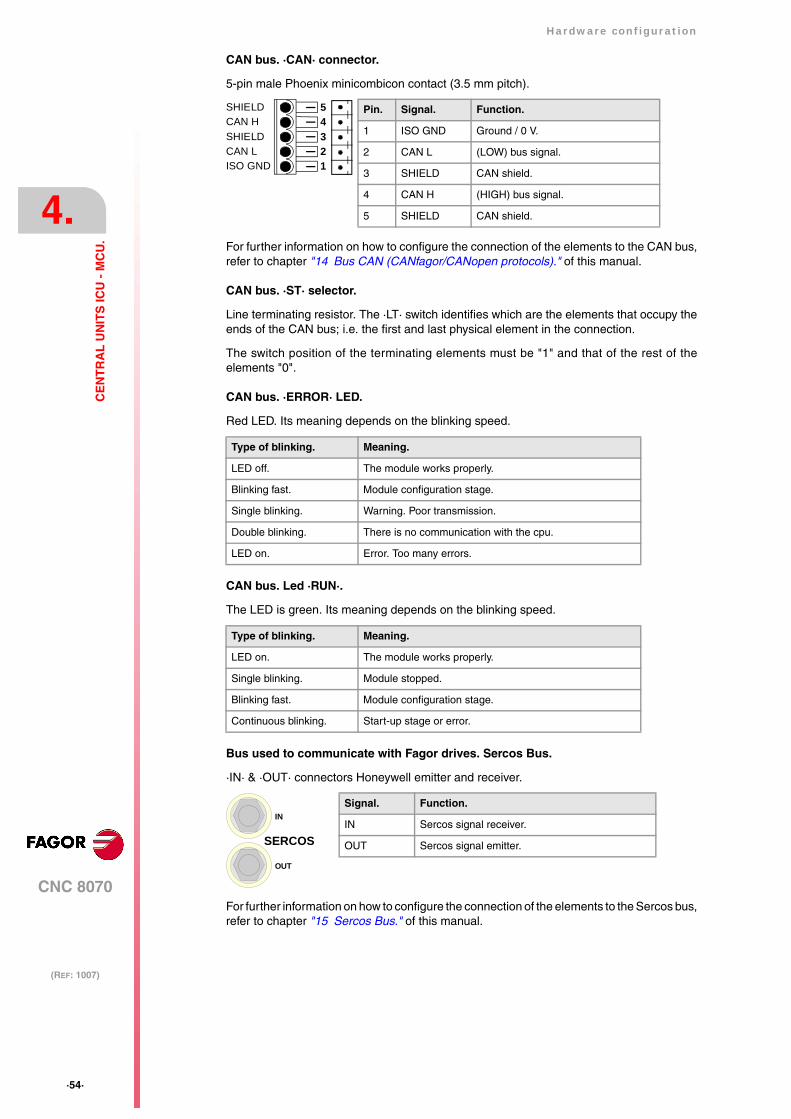
CAN bus. ·CAN· connector.
5-pin male Phoenix minicombicon contact (3.5 mm pitch).
For further information on how to configure the connection of the elements to the CAN bus,refer to chapter "14 Bus CAN (CANfagor/CANopen protocols)." of this manual.
CAN bus. ·ST· selector.
Line terminating resistor. The ·LT· switch identifies which are the elements that occupy theends of the CAN bus; i.e. the first and last physical element in the connection.
The switch position of the terminating elements must be "1" and that of the rest of theelements "0".
CAN bus. ·ERROR· LED.
Red LED. Its meaning depends on the blinking speed.
CAN bus. Led ·RUN·.
The LED is green. Its meaning depends on the blinking speed.
Bus used to communicate with Fagor drives. Sercos Bus.
·IN· & ·OUT· connectors Honeywell emitter and receiver.
For further information on how to configure the connection of the elements to the Sercos bus,refer to chapter "15 Sercos Bus." of this manual.
Type of blinking. Meaning.
LED off. The module works properly.
Blinking fast. Module configuration stage.
Single blinking. Warning. Poor transmission.
Double blinking. There is no communication with the cpu.
LED on. Error. Too many errors.
Type of blinking. Meaning.
LED on. The module works properly.
Single blinking. Module stopped.
Blinking fast. Module configuration stage.
Continuous blinking. Start-up stage or error.
12345
ISO GNDCAN LSHIELDCAN HSHIELD Pin. Signal. Function.
1 ISO GND Ground / 0 V.
2 CAN L (LOW) bus signal.
3 SHIELD CAN shield.
4 CAN H (HIGH) bus signal.
5 SHIELD CAN shield.
Signal. Function.
IN Sercos signal receiver.
OUT Sercos signal emitter.SERCOS
IN
OUT
Hardware configuration
CNC 8070
4.
(REF: 1007)
·55·
CE
NT
RA
L U
NIT
S IC
U -
MC
U.
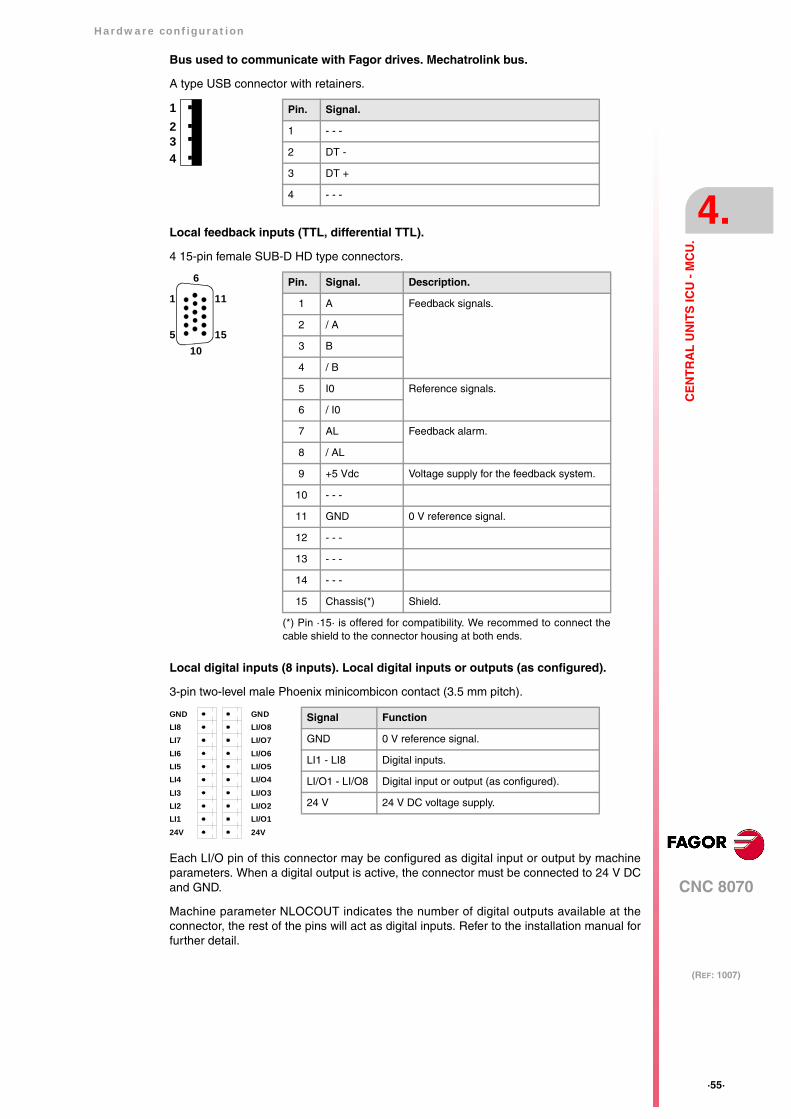
Bus used to communicate with Fagor drives. Mechatrolink bus.
A type USB connector with retainers.
Local feedback inputs (TTL, differential TTL).
4 15-pin female SUB-D HD type connectors.
Local digital inputs (8 inputs). Local digital inputs or outputs (as configured).
3-pin two-level male Phoenix minicombicon contact (3.5 mm pitch).
Each LI/O pin of this connector may be configured as digital input or output by machineparameters. When a digital output is active, the connector must be connected to 24 V DCand GND.
Machine parameter NLOCOUT indicates the number of digital outputs available at theconnector, the rest of the pins will act as digital inputs. Refer to the installation manual forfurther detail.
Pin. Signal.
1 - - -
2 DT -
3 DT +
4 - - -
4
23
1
(*) Pin ·15· is offered for compatibility. We recommed to connect thecable shield to the connector housing at both ends.
Pin. Signal. Description.
1 A Feedback signals.
2 / A
3 B
4 / B
5 I0 Reference signals.
6 / I0
7 AL Feedback alarm.
8 / AL
9 +5 Vdc Voltage supply for the feedback system.
10 - - -
11 GND 0 V reference signal.
12 - - -
13 - - -
14 - - -
15 Chassis(*) Shield.
11
15
6
10
1
5
Signal Function
GND 0 V reference signal.
LI1 - LI8 Digital inputs.
LI/O1 - LI/O8 Digital input or output (as configured).
24 V 24 V DC voltage supply.
GNDLI8LI7LI6LI5LI4LI3LI2LI124V
GNDLI/O8LI/O7LI/O6LI/O5LI/O4LI/O3LI/O2LI/O124V
·56·
Hardware configuration
CNC 8070
4.
(REF: 1007)
CE
NT
RA
L U
NIT
S IC
U -
MC
U.
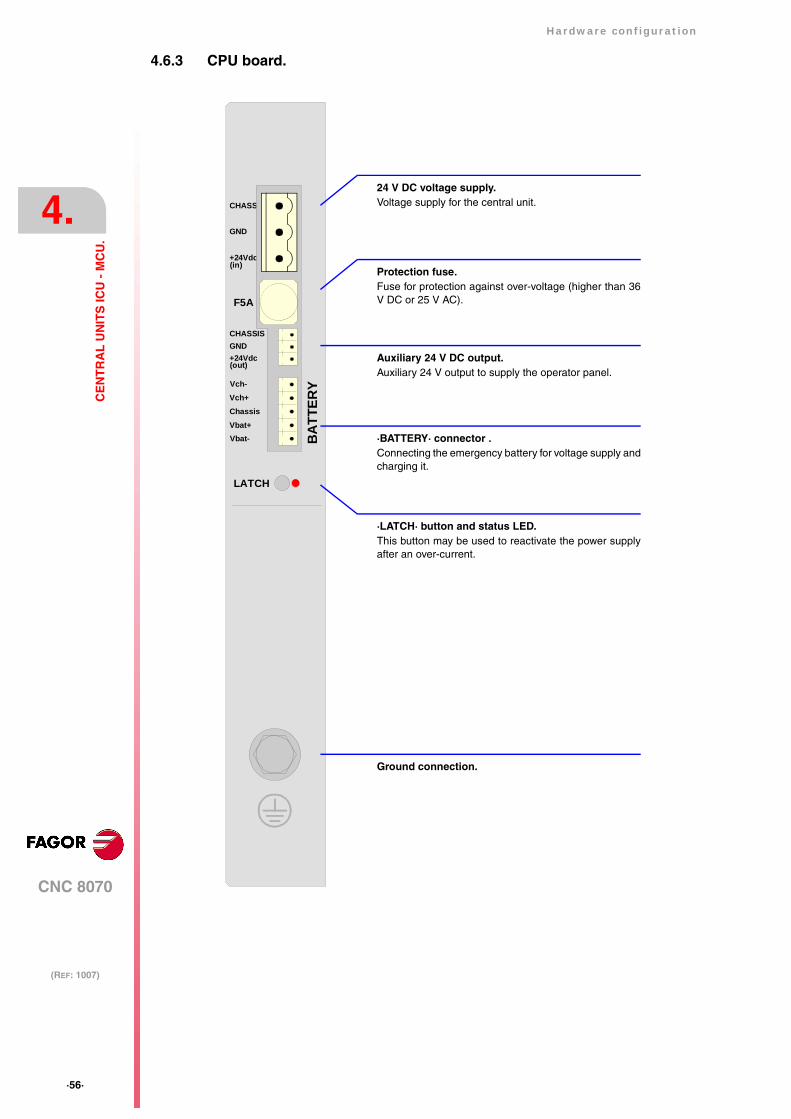
4.6.3 CPU board.
CHASSIS
+24Vdc
LATCH
F5A
CHASSISGND+24Vdc(out)
Vch-Vch+ChassisVbat+Vbat- B
ATT
ERY
GND
(in)
·BATTERY· connector .Connecting the emergency battery for voltage supply andcharging it.
Ground connection.
Auxiliary 24 V DC output.Auxiliary 24 V output to supply the operator panel.
Protection fuse.Fuse for protection against over-voltage (higher than 36V DC or 25 V AC).
·LATCH· button and status LED.This button may be used to reactivate the power supplyafter an over-current.
24 V DC voltage supply.Voltage supply for the central unit.
Hardware configuration
CNC 8070
4.
(REF: 1007)
·57·
CE
NT
RA
L U
NIT
S IC
U -
MC
U.
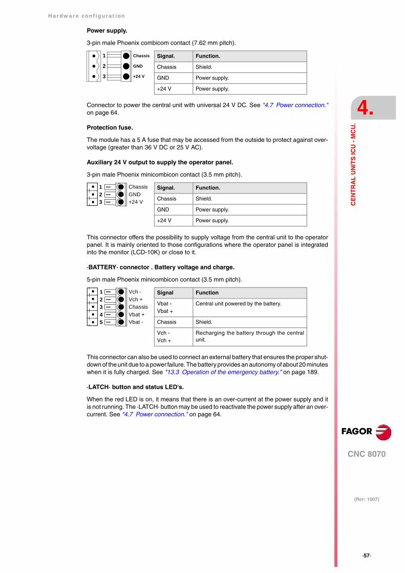
Power supply.
3-pin male Phoenix combicom contact (7.62 mm pitch).
Connector to power the central unit with universal 24 V DC. See "4.7 Power connection."on page 64.
Protection fuse.
The module has a 5 A fuse that may be accessed from the outside to protect against over-voltage (greater than 36 V DC or 25 V AC).
Auxiliary 24 V output to supply the operator panel.
3-pin male Phoenix minicombicon contact (3.5 mm pitch).
This connector offers the possibility to supply voltage from the central unit to the operatorpanel. It is mainly oriented to those configurations where the operator panel is integratedinto the monitor (LCD-10K) or close to it.
·BATTERY· connector . Battery voltage and charge.
5-pin male Phoenix minicombicon contact (3.5 mm pitch).
This connector can also be used to connect an external battery that ensures the proper shut-down of the unit due to a power failure. The battery provides an autonomy of about 20 minuteswhen it is fully charged. See "13.3 Operation of the emergency battery." on page 189.
·LATCH· button and status LED's.
When the red LED is on, it means that there is an over-current at the power supply and itis not running. The ·LATCH· button may be used to reactivate the power supply after an over-current. See "4.7 Power connection." on page 64.
3
2
1
+24 V
GND
Chassis Signal. Function.
Chassis Shield.
GND Power supply.
+24 V Power supply.
321
+24 VGNDChassis Signal. Function.
Chassis Shield.
GND Power supply.
+24 V Power supply.
54321
Vbat -Vbat +ChassisVch +Vch - Signal Function
Vbat -Vbat +
Central unit powered by the battery.
Chassis Shield.
Vch -Vch +
Recharging the battery through the centralunit.
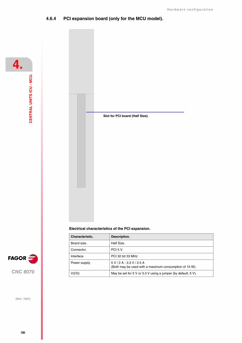
·58·
Hardware configuration
CNC 8070
4.
(REF: 1007)
CE
NT
RA
L U
NIT
S IC
U -
MC
U.
4.6.4 PCI expansion board (only for the MCU model).
Electrical characteristics of the PCI expansion.
Characteristic. Description.
Board size. Half Size.
Connector. PCI 5 V.
Interface. PCI 32 bit 33 MHz
Power supply. 5 V / 2 A - 3.3 V / 2.5 A(Both may be used with a maximum consumption of 15 W).
V(I/O) May be set for 5 V or 3.3 V using a jumper (by default, 5 V).
Slot for PCI board (Half Size).

Hardware configuration
CNC 8070
4.
(REF: 1007)
·59·
CE
NT
RA
L U
NIT
S IC
U -
MC
U.
Jumper ·JP1·. Voltage selector V(I/O).
3-pin jumper for selecting the voltage of V(I/O).
·JP1· Selected voltage.
5 V
3.3 V
5 VV(I/O)3.3 V
JP1
5 VV(I/O)3.3 V
5 VV(I/O)3.3 V

·60·
Hardware configuration
CNC 8070
4.
(REF: 1007)
CE
NT
RA
L U
NIT
S IC
U -
MC
U.
4.6.5 Operator panel (only LCD-10K)
Connector ·X11·. Handwheel connection.
10-pin male Phoenix minicombicon contact (3.5 mm pitch).
The keyboard admits the connection of up to 3 handwheels (MPG1, MPG2 and MPG3) withA and B signals (5 V DC TTL). If he handwheel has an axis selector button, the button signalmay be connected to a digital input and may be managed from the PLC using the -NEXTMPGAXIS-mark.
Pin Signal Function
1 +5 V Power supply.
2 - - -
3 - - -
4 MPG3-B B signal of the third handwheel.
5 MPG3-A A signal of the third handwheel.
6 MPG2-B B signal of the second handwheel.
7 MPG2-A A signal of the second handwheel.
8 MPG1-B B signal of the first handwheel.
9 MPG1-A A signal of the first handwheel.
10 GND Power supply.
789 3456 1210
MP
G2-
BM
PG
2-A
MP
G1-
BM
PG
1-A
GN
D
MP
G3-
BM
PG
3-A
5 V
DC
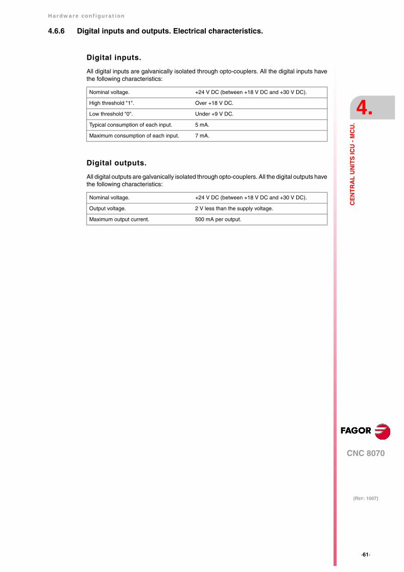
Hardware configuration
CNC 8070
4.
(REF: 1007)
·61·
CE
NT
RA
L U
NIT
S IC
U -
MC
U.
4.6.6 Digital inputs and outputs. Electrical characteristics.
Digital inputs.
All digital inputs are galvanically isolated through opto-couplers. All the digital inputs havethe following characteristics:
Digital outputs.
All digital outputs are galvanically isolated through opto-couplers. All the digital outputs havethe following characteristics:
Nominal voltage. +24 V DC (between +18 V DC and +30 V DC).
High threshold "1". Over +18 V DC.
Low threshold "0". Under +9 V DC.
Typical consumption of each input. 5 mA.
Maximum consumption of each input. 7 mA.
Nominal voltage. +24 V DC (between +18 V DC and +30 V DC).
Output voltage. 2 V less than the supply voltage.
Maximum output current. 500 mA per output.

·62·
Hardware configuration
CNC 8070
4.
(REF: 1007)
CE
NT
RA
L U
NIT
S IC
U -
MC
U.
4.6.7 Feedback inputs. Technical characteristics and connection.
The central unit has 2 feedback inputs, valid for TTL and differential TTL signals.
Technical characteristics of the feedback inputs.
Power consumption: +5 V 1 A (250 mA per axis)
Work levels for TTL signal.
Work levels for differential TTL signal.
Maximum frequency: 400 kHz.
Maximum gap between flanks: 460 ns.
Phase shift: 90º ± 20º.
High threshold (logic level “1”) VIH: 1.25 V < VIH < 7 V.
Umbral bajo (nivel lógico “0”) VIL: -7 V < VIL < 1 V.
Maximum voltage: ± 7 V.
Hysteresis: 0,25 V.
Maximum differential input current: 3 mA.
Maximum frequency: 1000 kHz.
Maximum gap between flanks: 460 ns.
Phase shift: 90º ± 20º.
Maximum voltage in common mode: ± 7 V.
Maximum voltage in differential mode: ± 6 V.
Hysteresis: 0.2 V.
Maximum differential input current: 3 mA.
A
B
Io
A
B
Io
A
B
Io
Hardware configuration
CNC 8070
4.
(REF: 1007)
·63·
CE
NT
RA
L U
NIT
S IC
U -
MC
U.
Feedback cable characteristics.
The cable used must have overall shield; the rest of the characteristics of the cable, as wellas its length, will depend on the type of feedback device used. Refer to our catalog.
The shield of the cable being used must be connected to the connector housing at both ends.The unshielded portion of the wires of an unshielded cable cannot be longer than 75 mm.
We recommend to run the feedback cables as far away as possible from the power cablesof the machine.
Fagor Automation offers a wide range of cables and extension cables to connect the feedback systemsto the CNC. Refer to our catalog for further information.
·64·
Hardware configuration
CNC 8070
4.
(REF: 1007)
CE
NT
RA
L U
NIT
S IC
U -
MC
U.
4.7 Power connection.
Voltage supply for the central unit.
The central unit is powered by an external DC power supply; use a 24 V DC ±10% and 3.5A. power supply.
It is also possible to connect an external battery that ensures the proper operation of the unitunder AC power outages. See chapter "13 Emergency battery.".
Over-current at the power supply.
An over-current activates the safety device inside the power supply turns on the external redLED. The power supply will not be operative while the LED is on. There are two ways toreactivate the power supply after an over-current.
• Unplug the power supply from mains and wait for about 30 seconds until the red lightturns off.
• Unplug the power supply and press the ·LATCH· button. The red LED will turn offindicating that the power supply is ready.
If after reactivating the power supply, the LED turns back on, call the Technical ServiceDepartment.
Consult the electrical characteristics of the central unit before connecting the power supply. See"4.1 Technical characteristics." on page 39.
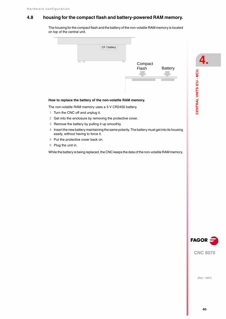
Hardware configuration
CNC 8070
4.
(REF: 1007)
·65·
CE
NT
RA
L U
NIT
S IC
U -
MC
U.
4.8 housing for the compact flash and battery-powered RAM memory.
The housing for the compact flash and the battery of the non-volatile RAM memory is locatedon top of the central unit.
How to replace the battery of the non-volatile RAM memory.
The non-volatile RAM memory uses a 3 V CR2450 battery.
1 Turn the CNC off and unplug it.
2 Get into the enclosure by removing the protective cover.
3 Remove the battery by pulling it up smoothly.
4 Insert the new battery maintaining the same polarity. The battery must get into its housingeasily, without having to force it.
5 Put the protective cover back on.
6 Plug the unit in.
While the battery is being replaced, the CNC keeps the data of the non-volatile RAM memory.
CF / battery
BatteryCompactFlash

·66·
Hardware configuration
CNC 8070
4.
(REF: 1007)
CE
NT
RA
L U
NIT
S IC
U -
MC
U.
4.9 Insert the board into the PCI expansion (only in MCU models).
Precaution when handling the boards.
Handle the boards very carefully to avoid damaging them or their elements, contacts orconducting lines. Place the modules in the correct position. Do not use a sharp-pointed object(like a screwdriver) as a lever.
• Before handling the ESD boards, discharge their static electricity (for example bytouching an object that is connected to ground).
• The units and tools being used must be free of any static charge-
• Turn the power supply of the unit off before inserting or removing the board.
• Hold the ESD board only at its corners or edges; do not touch its components, contactsor conducting lines.
Voltage for the pins V(I/O).
The supply voltage for the V(I/O) pins of the connector may be set for 5 V or 3.3 V (by default,5 V). See "4.6.4 PCI expansion board (only for the MCU model)." on page 58.
Mounting the boards.
This symbol identifies the cards as ESD components (sensitive to electrostaticdischarges). Bear in mind the following considerations when handing boards withESD:
Do not open the unit or handle the internal boards while the unit is connected to power. Before openingthe unit, make sure that the unit is unplugged from the power outlet.
Remove the three mounting screws (A) of the lid,located on top and slide the lid in the direction of thearrow (B).
Loosen the locking angle bracket (C) and turn it to allowthe board to slide in. Insert the board in the slot (D) andpush it in the direction of the arrow (E) all the way in.
A
A
A
B
C
D
E
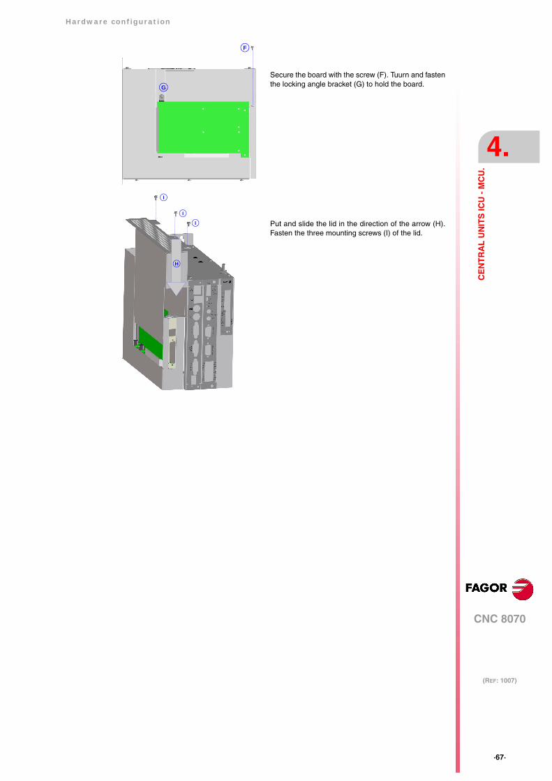
Hardware configuration
CNC 8070
4.
(REF: 1007)
·67·
CE
NT
RA
L U
NIT
S IC
U -
MC
U.
Secure the board with the screw (F). Tuurn and fastenthe locking angle bracket (G) to hold the board.
Put and slide the lid in the direction of the arrow (H).Fasten the three mounting screws (I) of the lid.
G
F
I
I
I
H
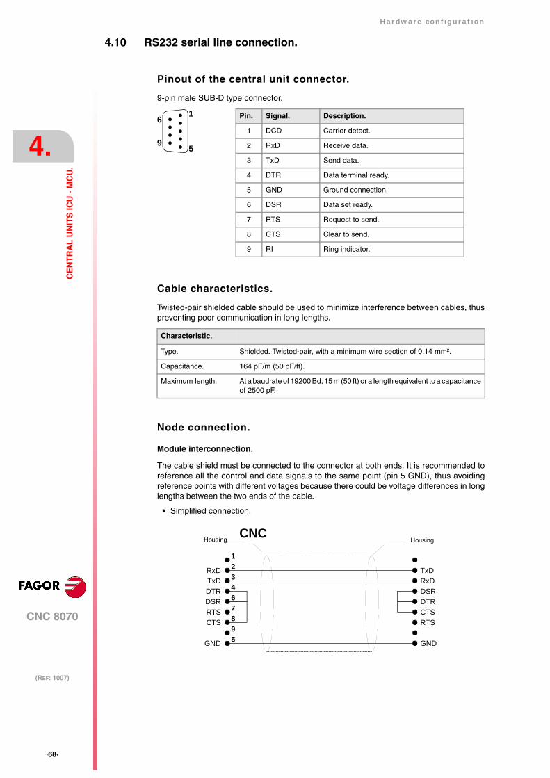
·68·
Hardware configuration
CNC 8070
4.
(REF: 1007)
CE
NT
RA
L U
NIT
S IC
U -
MC
U.
4.10 RS232 serial line connection.
Pinout of the central unit connector.
9-pin male SUB-D type connector.
Cable characteristics.
Twisted-pair shielded cable should be used to minimize interference between cables, thuspreventing poor communication in long lengths.
Node connection.
Module interconnection.
The cable shield must be connected to the connector at both ends. It is recommended toreference all the control and data signals to the same point (pin 5 GND), thus avoidingreference points with different voltages because there could be voltage differences in longlengths between the two ends of the cable.
Characteristic.
Type. Shielded. Twisted-pair, with a minimum wire section of 0.14 mm².
Capacitance. 164 pF/m (50 pF/ft).
Maximum length. At a baudrate of 19200 Bd, 15 m (50 ft) or a length equivalent to a capacitanceof 2500 pF.
• Simplified connection.
Pin. Signal. Description.
1 DCD Carrier detect.
2 RxD Receive data.
3 TxD Send data.
4 DTR Data terminal ready.
5 GND Ground connection.
6 DSR Data set ready.
7 RTS Request to send.
8 CTS Clear to send.
9 RI Ring indicator.
1
5
6
9
TxDRxD
DSR 6
32
5987
HousingHousing
1
4
CNC
RxDTxD
DTR
GND GND
CTS
DTR
RTS
DSR
RTS CTS
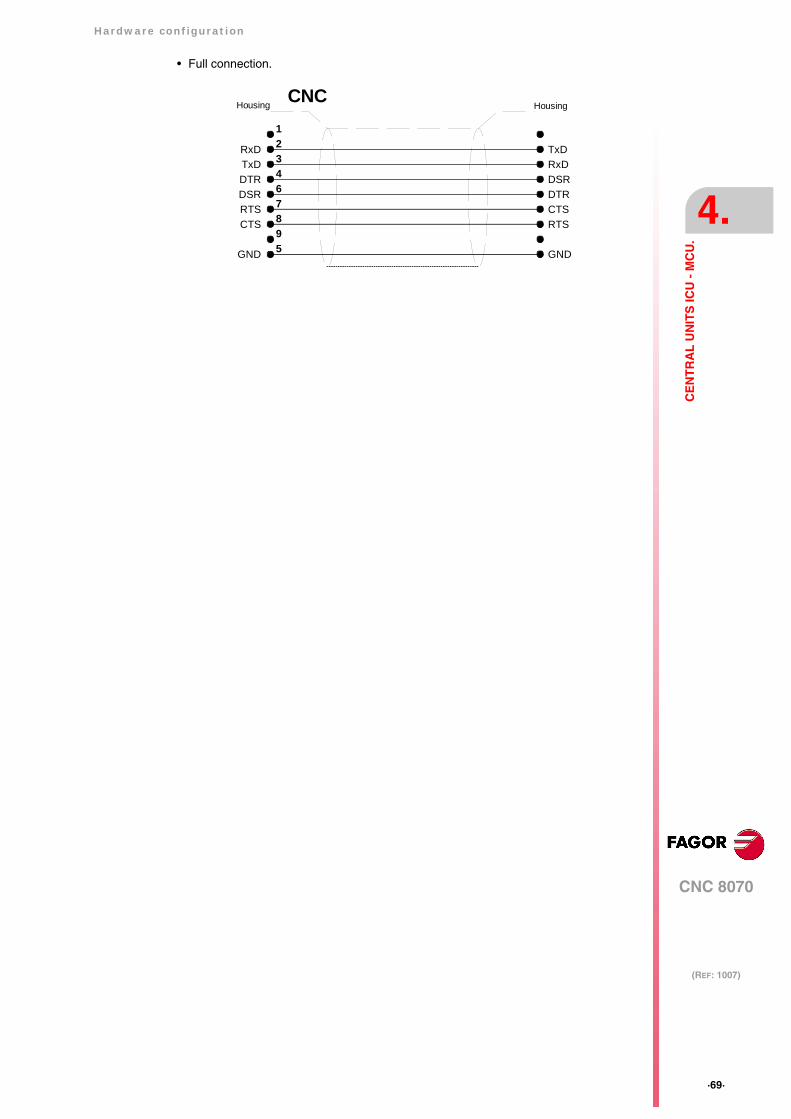
Hardware configuration
CNC 8070
4.
(REF: 1007)
·69·
CE
NT
RA
L U
NIT
S IC
U -
MC
U.
• Full connection.
TxDRxD
DSR 6
32
5987
HousingHousing
1
4
CNC
RxDTxD
DTR
GND GND
CTS
DTR
RTS
DSR
RTS CTS

·70·
Hardware configuration
CNC 8070
4.
(REF: 1007)
CE
NT
RA
L U
NIT
S IC
U -
MC
U.
4.11 RS422 serial line connection.
Pinout of the central unit connector.
9-pin male SUB-D type connector.
The reserved pins must NOT be used in any case.
Cable characteristics.
Twisted-pair shielded cable should be used to minimize interference between cables, thuspreventing poor communication in long lengths.
Node connection.
Line terminating resistor.
Module interconnection.
The cable shield must be connected to the connector at both ends. It is recommended toreference all the control and data signals to the same point (pin 5 GND), thus avoidingreference points with different voltages because there could be voltage differences in longlengths between the two ends of the cable.
Characteristic.
Type. Shielded. Twisted-pair, with a minimum wire section of 0.20 mm² (24 AWG).
Impedance. 120Ω.
Maximum length. 1200 m (3937 ft).
All the elements of the bus must have the line terminating resistoractivated. The central unit has the resistor inside at pins 2 and 3; toactivate it, jumper pin 2 with pin 8 and pin 3 with 9.
Pin. Signal. Description.
1 - - - - - -
2 LineTerm 120Ω line terminating resistor.
3 LineTerm 120Ω line terminating resistor.
4 - - - - - -
5 GND Ground connection.
6 TxD Send data.
7 /TxD Send data.
8 RxD Receive data.
9 /RxD Receive data.
1
5
6
9
Pin
GND
/Line TermLine Term
54321
9876
/RxDRxD/TxDTxD
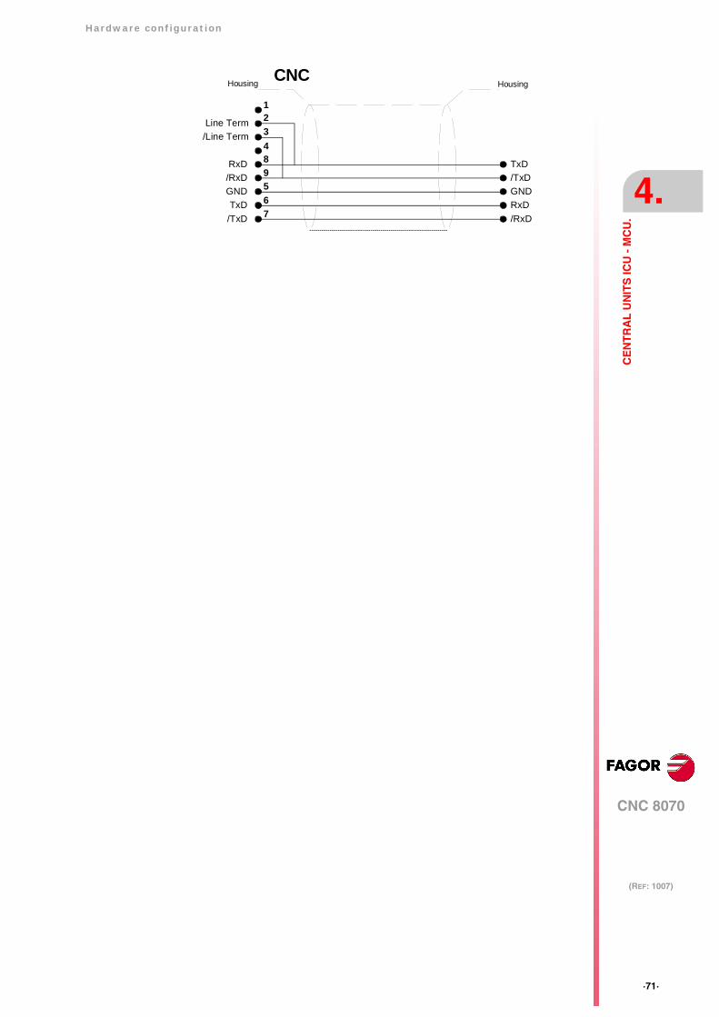
Hardware configuration
CNC 8070
4.
(REF: 1007)
·71·
CE
NT
RA
L U
NIT
S IC
U -
MC
U.
RxD
/Line TermLine Term
/TxDTxD
GND/RxD
8
32
7659
/RxDRxDGND
HousingHousing
1
4
CNC
/TxDTxD
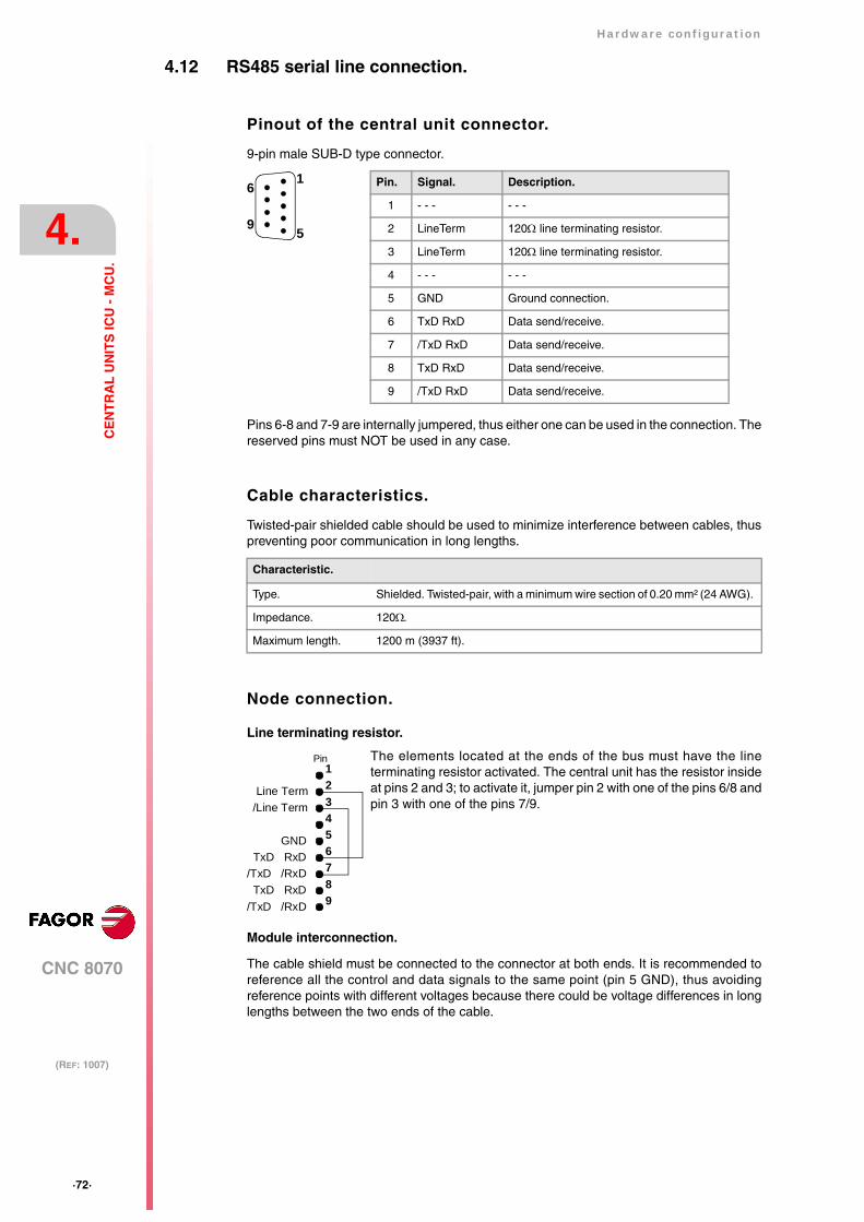
·72·
Hardware configuration
CNC 8070
4.
(REF: 1007)
CE
NT
RA
L U
NIT
S IC
U -
MC
U.
4.12 RS485 serial line connection.
Pinout of the central unit connector.
9-pin male SUB-D type connector.
Pins 6-8 and 7-9 are internally jumpered, thus either one can be used in the connection. Thereserved pins must NOT be used in any case.
Cable characteristics.
Twisted-pair shielded cable should be used to minimize interference between cables, thuspreventing poor communication in long lengths.
Node connection.
Line terminating resistor.
Module interconnection.
The cable shield must be connected to the connector at both ends. It is recommended toreference all the control and data signals to the same point (pin 5 GND), thus avoidingreference points with different voltages because there could be voltage differences in longlengths between the two ends of the cable.
Characteristic.
Type. Shielded. Twisted-pair, with a minimum wire section of 0.20 mm² (24 AWG).
Impedance. 120Ω.
Maximum length. 1200 m (3937 ft).
The elements located at the ends of the bus must have the lineterminating resistor activated. The central unit has the resistor insideat pins 2 and 3; to activate it, jumper pin 2 with one of the pins 6/8 andpin 3 with one of the pins 7/9.
Pin. Signal. Description.
1 - - - - - -
2 LineTerm 120Ω line terminating resistor.
3 LineTerm 120Ω line terminating resistor.
4 - - - - - -
5 GND Ground connection.
6 TxD RxD Data send/receive.
7 /TxD RxD Data send/receive.
8 TxD RxD Data send/receive.
9 /TxD RxD Data send/receive.
1
5
6
9
Pin
GND
/Line TermLine Term
54321
9876
/TxD /RxDTxD RxD
/TxD /RxDTxD RxD

Hardware configuration
CNC 8070
4.
(REF: 1007)
·73·
CE
NT
RA
L U
NIT
S IC
U -
MC
U.
TxD RxD
/Line TermLine Term
/TxD /RxDTxD RxD
GND/TxD /RxD
6
32
9857
/TxD /RxDTxD RxDGND
HousingHousing
1
4
CNC
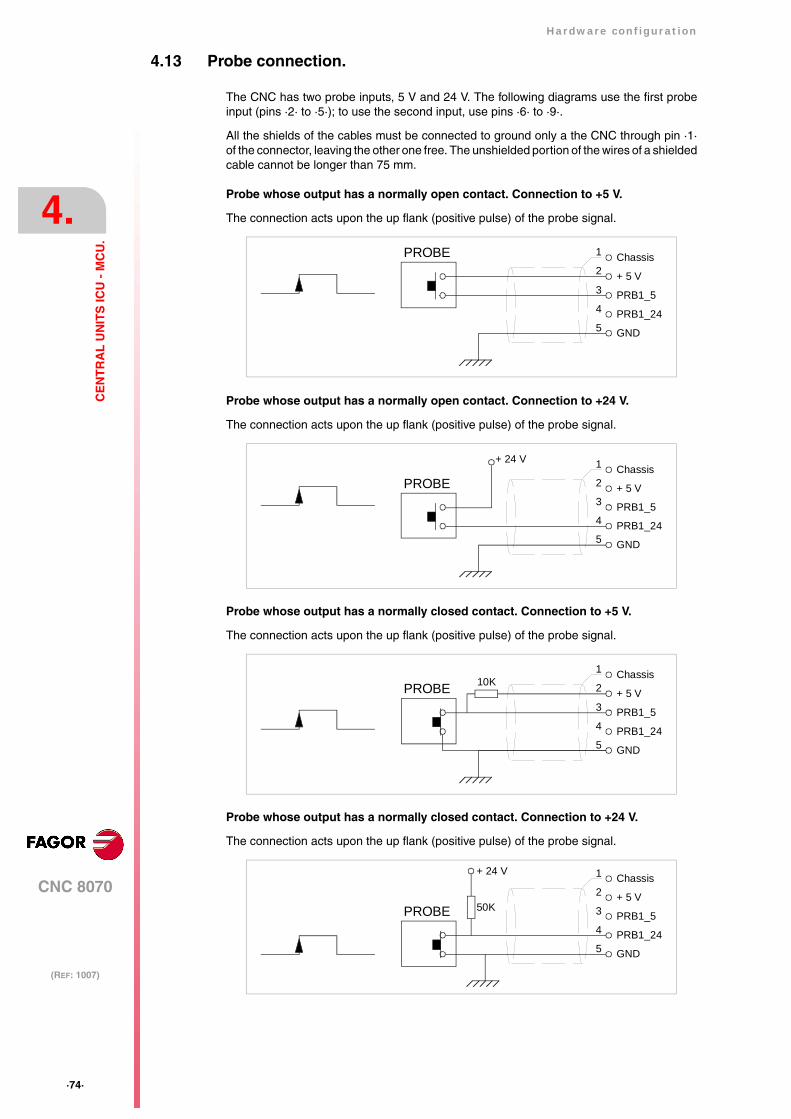
·74·
Hardware configuration
CNC 8070
4.
(REF: 1007)
CE
NT
RA
L U
NIT
S IC
U -
MC
U.
4.13 Probe connection.
The CNC has two probe inputs, 5 V and 24 V. The following diagrams use the first probeinput (pins ·2· to ·5·); to use the second input, use pins ·6· to ·9·.
All the shields of the cables must be connected to ground only a the CNC through pin ·1·of the connector, leaving the other one free. The unshielded portion of the wires of a shieldedcable cannot be longer than 75 mm.
Probe whose output has a normally open contact. Connection to +5 V.
The connection acts upon the up flank (positive pulse) of the probe signal.
Probe whose output has a normally open contact. Connection to +24 V.
The connection acts upon the up flank (positive pulse) of the probe signal.
Probe whose output has a normally closed contact. Connection to +5 V.
The connection acts upon the up flank (positive pulse) of the probe signal.
Probe whose output has a normally closed contact. Connection to +24 V.
The connection acts upon the up flank (positive pulse) of the probe signal.
PROBE 1
2
5
3
4
Chassis
+ 5 V
GND
PRB1_5
PRB1_24
PROBE 1
2
5
3
4
Chassis
+ 5 V
GND
PRB1_5
PRB1_24
+ 24 V
PROBE 1
2
5
3
4
Chassis
+ 5 V
GND
PRB1_5
PRB1_24
10K
PROBE
1
2
5
3
4
Chassis
+ 5 V
GND
PRB1_5
PRB1_24
50K
+ 24 V
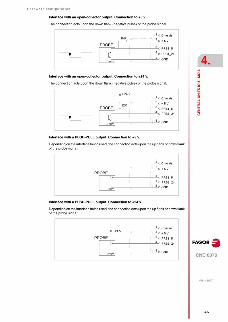
Hardware configuration
CNC 8070
4.
(REF: 1007)
·75·
CE
NT
RA
L U
NIT
S IC
U -
MC
U.
Interface with an open-collector output. Connection to +5 V.
The connection acts upon the down flank (negative pulse) of the probe signal.
Interface with an open-collector output. Connection to +24 V.
The connection acts upon the down flank (negative pulse) of the probe signal.
Interface with a PUSH-PULL output. Connection to +5 V.
Depending on the interface being used, the connection acts upon the up flank or down flankof the probe signal.
Interface with a PUSH-PULL output. Connection to +24 V.
Depending on the interface being used, the connection acts upon the up flank or down flankof the probe signal.
PROBE
1
2
5
3
4
Chassis
+ 5 V
GND
PRB1_5
PRB1_24
1K5
PROBE
1
2
5
3 4
Chassis
+ 5 V
GND
PRB1_5 PRB1_24
12K
+ 24 V
PROBE
1
2
5
3 4
Chassis
+ 5 V
GND
PRB1_5 PRB1_24
PROBE
1
2
5
3 4
Chassis
+ 5 V
GND
PRB1_5 PRB1_24
+ 24 V
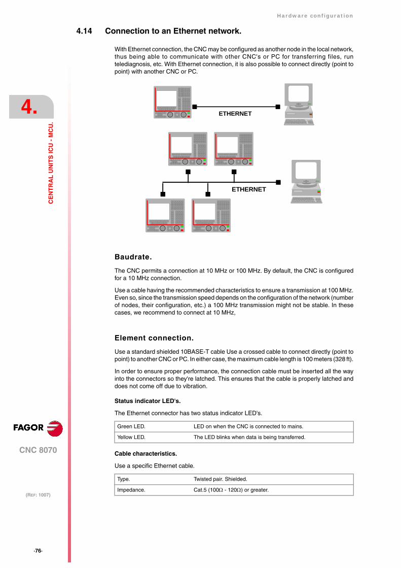
·76·
Hardware configuration
CNC 8070
4.
(REF: 1007)
CE
NT
RA
L U
NIT
S IC
U -
MC
U.
4.14 Connection to an Ethernet network.
With Ethernet connection, the CNC may be configured as another node in the local network,thus being able to communicate with other CNC's or PC for transferring files, runtelediagnosis, etc. With Ethernet connection, it is also possible to connect directly (point topoint) with another CNC or PC.
Baudrate.
The CNC permits a connection at 10 MHz or 100 MHz. By default, the CNC is configuredfor a 10 MHz connection.
Use a cable having the recommended characteristics to ensure a transmission at 100 MHz.Even so, since the transmission speed depends on the configuration of the network (numberof nodes, their configuration, etc.) a 100 MHz transmission might not be stable. In thesecases, we recommend to connect at 10 MHz,
Element connection.
Use a standard shielded 10BASE-T cable Use a crossed cable to connect directly (point topoint) to another CNC or PC. In either case, the maximum cable length is 100 meters (328 ft).
In order to ensure proper performance, the connection cable must be inserted all the wayinto the connectors so they're latched. This ensures that the cable is properly latched anddoes not come off due to vibration.
Status indicator LED's.
The Ethernet connector has two status indicator LED's.
Cable characteristics.
Use a specific Ethernet cable.
Green LED. LED on when the CNC is connected to mains.
Yellow LED. The LED blinks when data is being transferred.
Type. Twisted pair. Shielded.
Impedance. Cat.5 (100Ω - 120Ω) or greater.
ETHERNET
ETHERNET
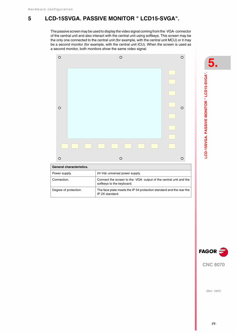
Hardware configuration
CNC 8070
5.
(REF: 1007)
·77·
LC
D-1
5SV
GA
. PA
SS
IVE
MO
NIT
OR
" L
CD
15-S
VG
A".
5 LCD-15SVGA. PASSIVE MONITOR " LCD15-SVGA".
The passive screen may be used to display the video signal coming from the ·VGA· connectorof the central unit and also interact with the central unit using softkeys. This screen may bethe only one connected to the central unit (for example, with the central unit MCU) or it maybe a second monitor (for example, with the central unit ICU). When the screen is used asa second monitor, both monitors show the same video signal.
General characteristics.
Power supply. 24 Vdc universal power supply.
Connection. Connect the screen to the ·VGA· output of the central unit and thesoftkeys to the keyboard.
Degree of protection. The face plate meets the IP 54 protection standard and the rear theIP 2X standard.
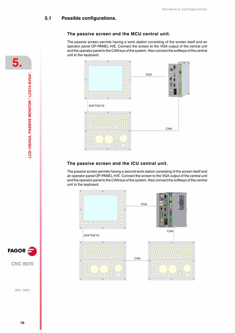
·78·
Hardware configuration
CNC 8070
5.
(REF: 1007)
LC
D-1
5SV
GA
. PA
SS
IVE
MO
NIT
OR
" L
CD
15-S
VG
A".
5.1 Possible configurations.
The passive screen and the MCU central unit.
The passive screen permits having a work station consisting of the screen itself and anoperator panel OP-PANEL-H/E. Connect the screen to the VGA output of the central unitand the operator panel to the CAN bus of the system. Also connect the softkeys of the centralunit to the keyboard.
The passive screen and the ICU central unit.
The passive screen permits having a second work station consisting of the screen itself andan operator panel OP-PANEL-H/E. Connect the screen to the VGA output of the central unitand the operator panel to the CAN bus of the system. Also connect the softkeys of the centralunit to the keyboard.
VGA
SOFTKEYS
CAN
VGA
SOFTKEYS
CAN
CAN

Hardware configuration
CNC 8070
5.
(REF: 1007)
·79·
LC
D-1
5SV
GA
. PA
SS
IVE
MO
NIT
OR
" L
CD
15-S
VG
A".
5.2 Technical characteristics.
Electrical characteristics.
The unit has an internal power supply with the following characteristics.
Unit protections.
• Internal 5 A fuse.
• Protection against over-voltage peaks (higher than 36 V D) and reverse voltage. It is alsoprotected against reverse connection of the power supply, preventing it from starting up.
• Protection against over-current.
Vibrations.
• Sweep sine trial with a frequency step of 1 octave/minute (±10%) and 10 sweeps long.
Packaging and resistance to falls.
• Packaging: Meets the EN 60068-2-32 regulation.
• Free fall packaged according to Fagor regulations (1 meter):
Ambient conditions.
• Relative humidity: 10-95% without condensation.
• Work temperature: 0-45 ºC with an average lower than 35 ºC.
• Storage temperature: Between -40 ºC ( 77 ºF) and +70 ºC (158 ºF).
• Maximum work altitude: Meets the IEC 1131-2 standard.
Degree of protection.
• Front panel: It meets the protection standard IP 54.
• Rear panel: It meets the protection standard IP 2X.
Electrical characteristics.
Input voltage. 24 V DC ±10% and 2 A.
Efficiency. Greater than 80%.
Insulation. 1000 V DC; 1 minute.
9 Hz ≥ f ≥ 5 Hz Constant movement with an amplitude of 3,5 mm.
150 Hz ≥ f ≥ 9 Hz Constant 1g acceleration.
Do not get into the inside of the unit. This unit MUST NOT be opened by unauthorized personnel. Onlypersonnel authorized by Fagor Automation may manipulate the inside of this unit.

·80·
Hardware configuration
CNC 8070
5.
(REF: 1007)
LC
D-1
5SV
GA
. PA
SS
IVE
MO
NIT
OR
" L
CD
15-S
VG
A".
5.3 Hardware dimensions.
mm inchDa 200 7,87Db 165 6,50Dd 4,5 0,18ØA 8,5 0,33ØB 5 0,20
mm incha 420 16,54b 350 13,78c 52 2,05d 81,5 3,21e 155 6,10f 43,8 1,72g 271 10,67
c
d
e
a
b
Da Da
Db
Db
f g
A
Dd
ØA ØB
A
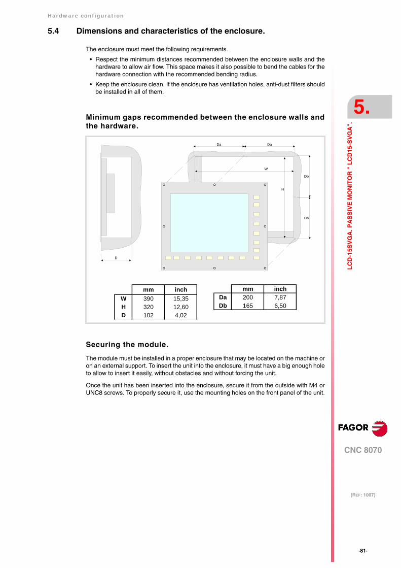
Hardware configuration
CNC 8070
5.
(REF: 1007)
·81·
LC
D-1
5SV
GA
. PA
SS
IVE
MO
NIT
OR
" L
CD
15-S
VG
A".
5.4 Dimensions and characteristics of the enclosure.
The enclosure must meet the following requirements.
• Respect the minimum distances recommended between the enclosure walls and thehardware to allow air flow. This space makes it also possible to bend the cables for thehardware connection with the recommended bending radius.
• Keep the enclosure clean. If the enclosure has ventilation holes, anti-dust filters shouldbe installed in all of them.
Minimum gaps recommended between the enclosure walls andthe hardware.
Securing the module.
The module must be installed in a proper enclosure that may be located on the machine oron an external support. To insert the unit into the enclosure, it must have a big enough holeto allow to insert it easily, without obstacles and without forcing the unit.
Once the unit has been inserted into the enclosure, secure it from the outside with M4 orUNC8 screws. To properly secure it, use the mounting holes on the front panel of the unit.
Da Da
W
H
Db
Db
D
mm inchW 390 15,35H 320 12,60D 102 4,02
mm inchDa 200 7,87Db 165 6,50
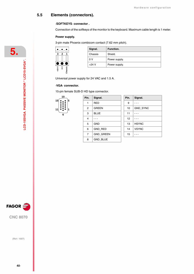
·82·
Hardware configuration
CNC 8070
5.
(REF: 1007)
LC
D-1
5SV
GA
. PA
SS
IVE
MO
NIT
OR
" L
CD
15-S
VG
A".
5.5 Elements (connectors).
·SOFTKEYS· connector .
Connection of the softkeys of the monitor to the keyboard. Maximum cable length is 1 meter.
Power supply.
3-pin male Phoenix combicom contact (7.62 mm pitch).
Universal power supply for 24 VAC and 1.5 A.
·VGA· connector.
15-pin female SUB-D HD type connector.
Signal. Function.
Chassis Shield.
0 V Power supply.
+24 V Power supply.
3 2 1+2
4 V
0 V
Cha
ssis
Pin. Signal.
1 RED
2 GREEN
3 BLUE
4 - - -
5 GND
6 GND_RED
7 GND_GREEN
8 GND_BLUE
Pin. Signal.
9 - - -
10 GND_SYNC
11 - - -
12 - - -
13 HSYNC
14 VSYNC
15 - - -
5
1
10
6
15
11
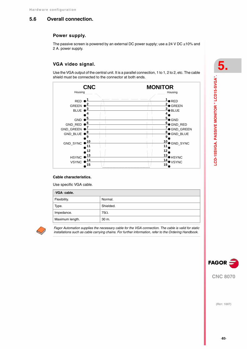
Hardware configuration
CNC 8070
5.
(REF: 1007)
·83·
LC
D-1
5SV
GA
. PA
SS
IVE
MO
NIT
OR
" L
CD
15-S
VG
A".
5.6 Overall connection.
Power supply.
The passive screen is powered by an external DC power supply; use a 24 V DC ±10% and2 A. power supply.
VGA video signal.
Use the VGA output of the central unit. It is a parallel connection, 1 to 1, 2 to 2, etc. The cableshield must be connected to the connector at both ends.
Cable characteristics.
Use specific VGA cable.
·VGA· cable.
Flexibility. Normal.
Type. Shielded.
Impedance. 75Ω.
Maximum length. 30 m.
GND
BLUEGREEN
GND_SYNC
GND_BLUEGND_GREEN
GND_RED
5
32
9876
HousingHousing
1
4
CNC
13
1110
1514
12
5
32
9876
1
4
13
1110
1514
12
MONITOR
RED
HSYNCVSYNC
GND
BLUEGREEN
GND_SYNC
GND_BLUEGND_GREENGND_RED
RED
HSYNCVSYNC
Fagor Automation supplies the necessary cable for the VGA connection. The cable is valid for staticinstallations such as cable carrying chains. For further information, refer to the Ordering Handbook.

·84·
Hardware configuration
CNC 8070
6.
(REF: 1007)
OP
-PA
NE
L-H
/E M
OD
UL
E. K
EY
BO
AR
D A
ND
OP
ER
AT
OR
PA
NE
L.
6 OP-PANEL-H/E MODULE. KEYBOARD AND OPERATORPANEL.
Set of alpha-numeric QWERTY keyboard with integrated operator panel. The operator panelhas either an emergency button (E-stop) or a handwheel.
General characteristics.
Power supply. 24 Vdc universal power supply.
Connection. Connection to the central unit through CAN bus.
Electronic handwheels. Possibility to connect up to three handwheels with A and B signals(5 V DC TTL).
Degree of protection. It meets the protection standard IP 54.
The machine manufacturer must comply with the EN 60204-1 (IEC-204-1) regulation regardingelectrical shocks in case of defective input/output pins with external power supply when not pluggingthe connector before turning the power supply on.
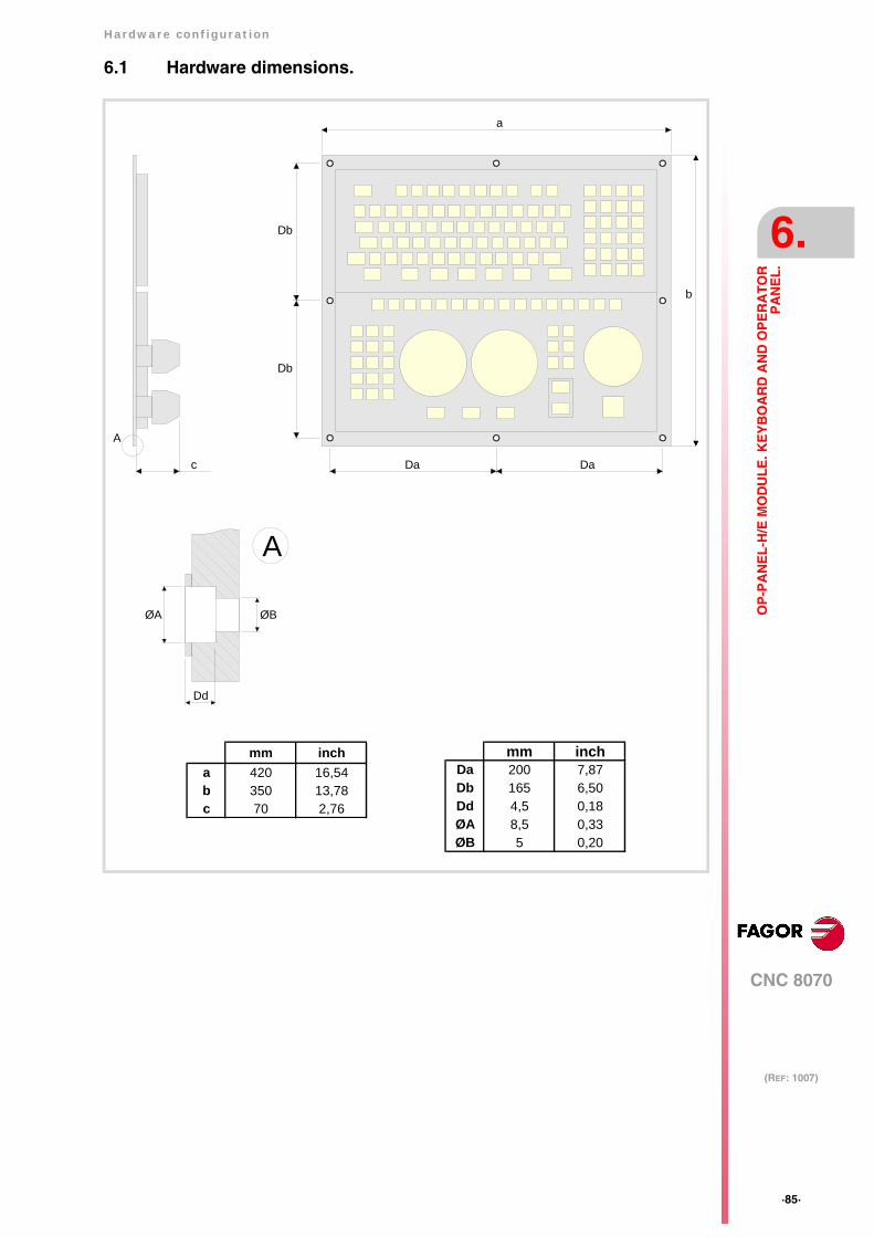
Hardware configuration
CNC 8070
6.
(REF: 1007)
·85·
OP
-PA
NE
L-H
/E M
OD
UL
E. K
EY
BO
AR
D A
ND
OP
ER
AT
OR
PA
NE
L.
6.1 Hardware dimensions.
mm inchDa 200 7,87Db 165 6,50Dd 4,5 0,18ØA 8,5 0,33ØB 5 0,20
a
b
Da Da
Db
Db
c
A
Dd
ØA ØB
A
mm incha 420 16,54b 350 13,78c 70 2,76
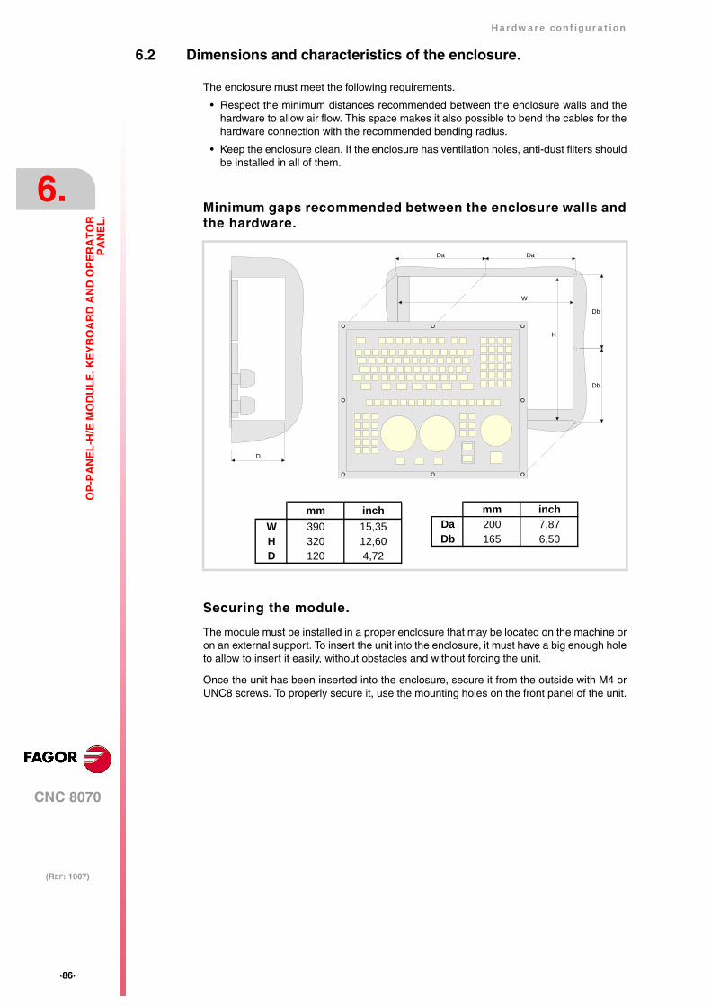
·86·
Hardware configuration
CNC 8070
6.
(REF: 1007)
OP
-PA
NE
L-H
/E M
OD
UL
E. K
EY
BO
AR
D A
ND
OP
ER
AT
OR
PA
NE
L.
6.2 Dimensions and characteristics of the enclosure.
The enclosure must meet the following requirements.
• Respect the minimum distances recommended between the enclosure walls and thehardware to allow air flow. This space makes it also possible to bend the cables for thehardware connection with the recommended bending radius.
• Keep the enclosure clean. If the enclosure has ventilation holes, anti-dust filters shouldbe installed in all of them.
Minimum gaps recommended between the enclosure walls andthe hardware.
Securing the module.
The module must be installed in a proper enclosure that may be located on the machine oron an external support. To insert the unit into the enclosure, it must have a big enough holeto allow to insert it easily, without obstacles and without forcing the unit.
Once the unit has been inserted into the enclosure, secure it from the outside with M4 orUNC8 screws. To properly secure it, use the mounting holes on the front panel of the unit.
mm inchW 390 15,35H 320 12,60D 120 4,72
mm inchDa 200 7,87Db 165 6,50
Da Da
W
H
Db
Db
D

Hardware configuration
CNC 8070
6.
(REF: 1007)
·87·
OP
-PA
NE
L-H
/E M
OD
UL
E. K
EY
BO
AR
D A
ND
OP
ER
AT
OR
PA
NE
L.
6.3 Elements (connectors).
The connectors are in the rear.
Keyboard of the central unit (only PC104).
Connection of the keys of the central unit PC104 to the keyboard; not being used in the othercentral units. Maximum cable length is 1 meter.
4
01FEDCBA98 7 6 5 32
A
·RESET· button.This button may be used to reset the module whenchanging the node number.
CAN bus. ·ADDRESS· selector.Address (node) of the element within the CAN bus.
Keyboard of the central unit.
Ground connection.The keyboard has two ground connection points; both must be connected.
Connectors overview.
24 V DCCANCANHANDWHEEL
ALT
SHIE
LDC
AN
HSH
IELD
CA
N L
ISO
GN
D
SHIE
LDC
AN
HSH
IELD
CA
N L
ISO
GN
D
24 V
DC
GN
D
GN
DM
PG1-
AM
PG1-
BM
PG2-
A
5 V
DC
MPG
3-B
MPG
3-A
MPG
2-B 0 11 2 3 4
OFF
ON1 2 3 4ON
ADD MSBSPEEDCAN F/O
CAN bus. ·ST· selector.Switch to activate the line termination resistor of theCAN bus.
CAN bus. ·CAN· connector.CAN bus connection.
24 V DC voltage supply.Voltage supply for the keyboard.
CAN bus. ·ADD MSB· selector and bus type.Selector for the type of CAN bus, speed for CANopen busand ·ADD MSB· selector.
Detailed view of the connectors.
·HANDWHEEL· connector.Handwheel connection.
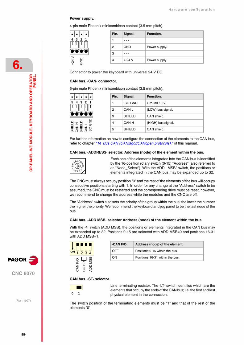
·88·
Hardware configuration
CNC 8070
6.
(REF: 1007)
OP
-PA
NE
L-H
/E M
OD
UL
E. K
EY
BO
AR
D A
ND
OP
ER
AT
OR
PA
NE
L.
Power supply.
4-pin male Phoenix minicombicon contact (3.5 mm pitch).
Connector to power the keyboard with universal 24 V DC.
CAN bus. ·CAN· connector.
5-pin male Phoenix minicombicon contact (3.5 mm pitch).
For further information on how to configure the connection of the elements to the CAN bus,refer to chapter "14 Bus CAN (CANfagor/CANopen protocols)." of this manual.
CAN bus. ·ADDRESS· selector. Address (node) of the element within the bus.
The CNC must always occupy position "0" and the rest of the elements of the bus will occupyconsecutive positions starting with 1. In order for any change at the "Address" switch to beassumed, the CNC must be restarted and the corresponding drive must be reset, however,we recommend to change the address while the modules and the CNC are off.
The "Address" switch also sets the priority of the group within the bus; the lower the numberthe higher the priority. We recommend the keyboard and jog panel to be the last node of thebus.
CAN bus. ·ADD MSB· selector Address (node) of the element within the bus.
With the ·4· switch (ADD MSB), the positions or elements integrated in the CAN bus maybe expanded up to 32. Positions 0-15 are selected with ADD MSB=0 and positions 16-31with ADD MSB=1.
CAN bus. ·ST· selector.
The switch position of the terminating elements must be "1" and that of the rest of theelements "0".
Each one of the elements integrated into the CAN bus is identifiedby the 16-position rotary switch (0-15) "Address" (also referred toas "Node_Select"). With the ADD MSB" switch, the positions orelements integrated in the CAN bus may be expanded up to 32.
Line terminating resistor. The ·LT· switch identifies which are theelements that occupy the ends of the CAN bus; i.e. the first and lastphysical element in the connection.
Pin. Signal. Function.
1 - - -
2 GND Power supply.
3 - - -
4 + 24 V Power supply.
GN
D
+24
V
1234
Pin. Signal. Function.
1 ISO GND Ground / 0 V.
2 CAN L (LOW) bus signal.
3 SHIELD CAN shield.
4 CAN H (HIGH) bus signal.
5 SHIELD CAN shield.
12345
ISO
GN
DC
AN L
SHIE
LDC
AN H
SHIE
LD
4
01FE
DCBA98 7 6 5 32
·CAN F/O· Address (node) of the element.
OFF Positions 0-15 within the bus.
ON Positions 16-31 within the bus.1 2 3 4ON
CAN
F/O
CO
BR
AD
D M
SB
0 1
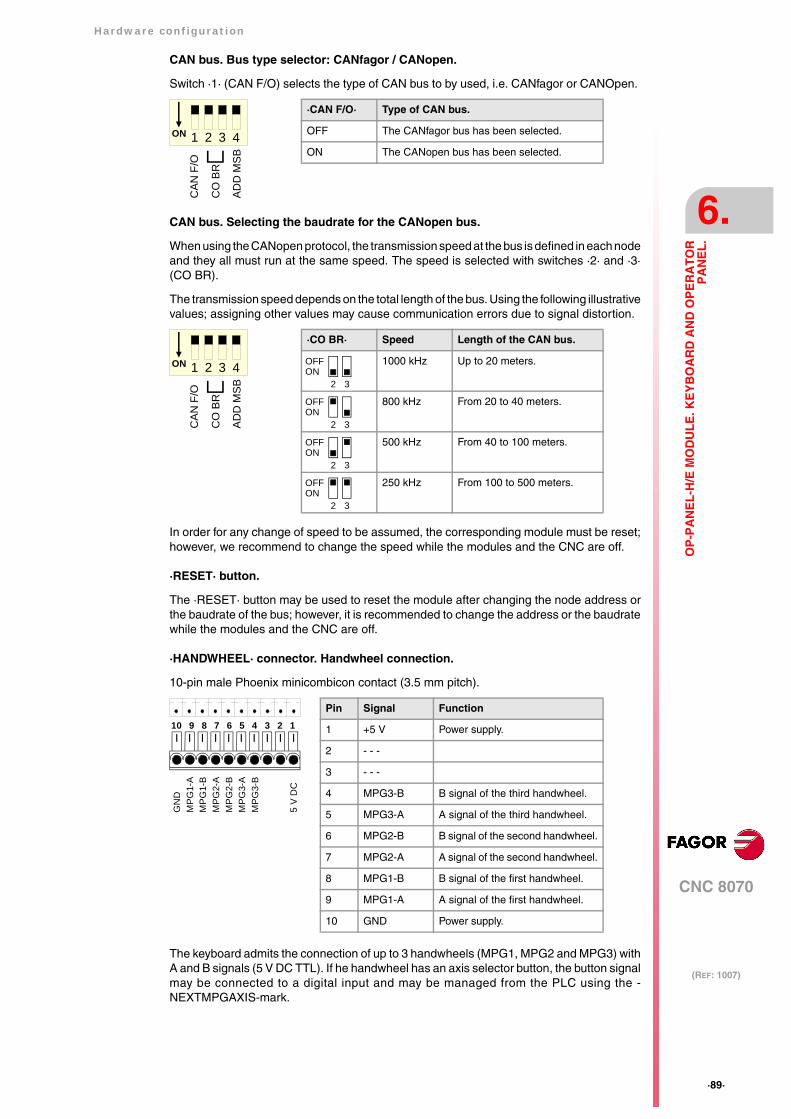
Hardware configuration
CNC 8070
6.
(REF: 1007)
·89·
OP
-PA
NE
L-H
/E M
OD
UL
E. K
EY
BO
AR
D A
ND
OP
ER
AT
OR
PA
NE
L.
CAN bus. Bus type selector: CANfagor / CANopen.
Switch ·1· (CAN F/O) selects the type of CAN bus to by used, i.e. CANfagor or CANOpen.
CAN bus. Selecting the baudrate for the CANopen bus.
When using the CANopen protocol, the transmission speed at the bus is defined in each nodeand they all must run at the same speed. The speed is selected with switches ·2· and ·3·(CO BR).
The transmission speed depends on the total length of the bus. Using the following illustrativevalues; assigning other values may cause communication errors due to signal distortion.
In order for any change of speed to be assumed, the corresponding module must be reset;however, we recommend to change the speed while the modules and the CNC are off.
·RESET· button.
The ·RESET· button may be used to reset the module after changing the node address orthe baudrate of the bus; however, it is recommended to change the address or the baudratewhile the modules and the CNC are off.
·HANDWHEEL· connector. Handwheel connection.
10-pin male Phoenix minicombicon contact (3.5 mm pitch).
The keyboard admits the connection of up to 3 handwheels (MPG1, MPG2 and MPG3) withA and B signals (5 V DC TTL). If he handwheel has an axis selector button, the button signalmay be connected to a digital input and may be managed from the PLC using the -NEXTMPGAXIS-mark.
·CAN F/O· Type of CAN bus.
OFF The CANfagor bus has been selected.
ON The CANopen bus has been selected.1 2 3 4ON
CAN
F/O
CO
BR
AD
D M
SB
·CO BR· Speed Length of the CAN bus.
1000 kHz Up to 20 meters.
800 kHz From 20 to 40 meters.
500 kHz From 40 to 100 meters.
250 kHz From 100 to 500 meters.
2 3
OFFON
2 3
OFFON
2 3
OFFON
2 3ONOFF
1 2 3 4ON
CAN
F/O
CO
BR
AD
D M
SB
Pin Signal Function
1 +5 V Power supply.
2 - - -
3 - - -
4 MPG3-B B signal of the third handwheel.
5 MPG3-A A signal of the third handwheel.
6 MPG2-B B signal of the second handwheel.
7 MPG2-A A signal of the second handwheel.
8 MPG1-B B signal of the first handwheel.
9 MPG1-A A signal of the first handwheel.
10 GND Power supply.
789 3456 1210
MP
G2-
BM
PG
2-A
MP
G1-
BM
PG
1-A
GN
D
MP
G3-
BM
PG
3-A
5 V
DC
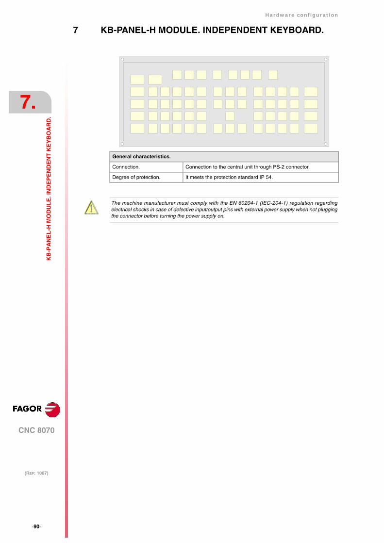
·90·
Hardware configuration
CNC 8070
7.
(REF: 1007)
KB
-PA
NE
L-H
MO
DU
LE
. IN
DE
PE
ND
EN
T K
EY
BO
AR
D.
7 KB-PANEL-H MODULE. INDEPENDENT KEYBOARD.
General characteristics.
Connection. Connection to the central unit through PS-2 connector.
Degree of protection. It meets the protection standard IP 54.
The machine manufacturer must comply with the EN 60204-1 (IEC-204-1) regulation regardingelectrical shocks in case of defective input/output pins with external power supply when not pluggingthe connector before turning the power supply on.

Hardware configuration
CNC 8070
7.
(REF: 1007)
·91·
KB
-PA
NE
L-H
MO
DU
LE
. IN
DE
PE
ND
EN
T K
EY
BO
AR
D.
7.1 Hardware dimensions.
mm inchDa 316 12,44Db 131 5,16Dc 4,5 0,18Ø 4,5 0,18
mm incha 325 12,80b 140 5,51c 50 1,97
a
b
Da
Db
c
A
Ø
A

·92·
Hardware configuration
CNC 8070
7.
(REF: 1007)
KB
-PA
NE
L-H
MO
DU
LE
. IN
DE
PE
ND
EN
T K
EY
BO
AR
D.
7.2 Dimensions and characteristics of the enclosure.
The enclosure must meet the following requirements.
• Respect the minimum distances recommended between the enclosure walls and thehardware to allow air flow. This space makes it also possible to bend the cables for thehardware connection with the recommended bending radius.
• Keep the enclosure clean. If the enclosure has ventilation holes, anti-dust filters shouldbe installed in all of them.
Minimum gaps recommended between the enclosure walls andthe hardware.
Securing the module.
The module must be installed in a proper enclosure that may be located on the machine oron an external support. To insert the unit into the enclosure, it must have a big enough holeto allow to insert it easily, without obstacles and without forcing the unit.
Once the unit has been inserted into the enclosure, secure it from the outside with M4 orUNC8 screws. To properly secure it, use the mounting holes on the front panel of the unit.
mm inchW 306 12,05H 121 4,76D 60 2,36
Da
WH
Db
D
mm inchDa 316 12,44Db 131 5,16

Hardware configuration
CNC 8070
7.
(REF: 1007)
·93·
KB
-PA
NE
L-H
MO
DU
LE
. IN
DE
PE
ND
EN
T K
EY
BO
AR
D.
7.3 Elements (connectors).
The connectors are in the rear.
Keyboard of the central unit (only PC104).
Connection of the keys of the central unit PC104 to the keyboard; not being used in the othercentral units. Maximum cable length is 1 meter.
PC-compatible keyboard.
6-pin minidin female connector.
Keyboard of the central unit.
Ground connection.
PC-compatible keyboard.
Pin. Signal.
1 Keyboard data.
2 - - -
3 GND
4 +5 V
5 Keyboard clock.
6 - - -
1
3
5
2
4
6
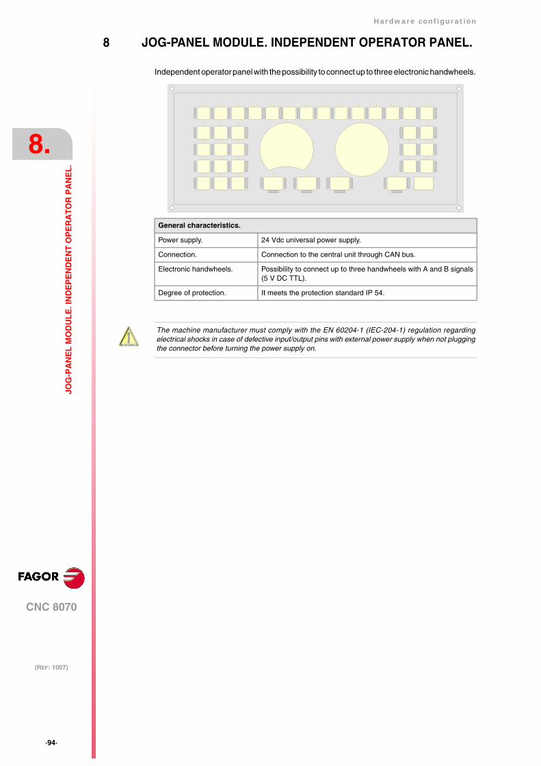
·94·
Hardware configuration
CNC 8070
8.
(REF: 1007)
JOG
-PA
NE
L M
OD
UL
E. I
ND
EP
EN
DE
NT
OP
ER
AT
OR
PA
NE
L.
8 JOG-PANEL MODULE. INDEPENDENT OPERATOR PANEL.
Independent operator panel with the possibility to connect up to three electronic handwheels.
General characteristics.
Power supply. 24 Vdc universal power supply.
Connection. Connection to the central unit through CAN bus.
Electronic handwheels. Possibility to connect up to three handwheels with A and B signals(5 V DC TTL).
Degree of protection. It meets the protection standard IP 54.
The machine manufacturer must comply with the EN 60204-1 (IEC-204-1) regulation regardingelectrical shocks in case of defective input/output pins with external power supply when not pluggingthe connector before turning the power supply on.
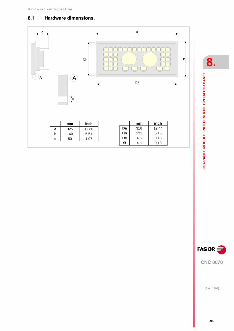
Hardware configuration
CNC 8070
8.
(REF: 1007)
·95·
JOG
-PA
NE
L M
OD
UL
E. I
ND
EP
EN
DE
NT
OP
ER
AT
OR
PA
NE
L.
8.1 Hardware dimensions.
mm inchDa 316 12,44Db 131 5,16Dc 4,5 0,18Ø 4,5 0,18
mm incha 325 12,80b 140 5,51c 50 1,97
a
b
Da
Db
c
A
Ø
A
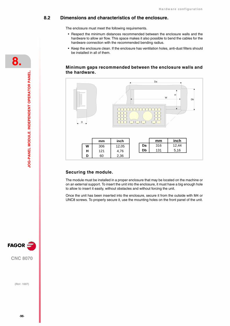
·96·
Hardware configuration
CNC 8070
8.
(REF: 1007)
JOG
-PA
NE
L M
OD
UL
E. I
ND
EP
EN
DE
NT
OP
ER
AT
OR
PA
NE
L.
8.2 Dimensions and characteristics of the enclosure.
The enclosure must meet the following requirements.
• Respect the minimum distances recommended between the enclosure walls and thehardware to allow air flow. This space makes it also possible to bend the cables for thehardware connection with the recommended bending radius.
• Keep the enclosure clean. If the enclosure has ventilation holes, anti-dust filters shouldbe installed in all of them.
Minimum gaps recommended between the enclosure walls andthe hardware.
Securing the module.
The module must be installed in a proper enclosure that may be located on the machine oron an external support. To insert the unit into the enclosure, it must have a big enough holeto allow to insert it easily, without obstacles and without forcing the unit.
Once the unit has been inserted into the enclosure, secure it from the outside with M4 orUNC8 screws. To properly secure it, use the mounting holes on the front panel of the unit.
Da
WH
Db
D
mm inchW 306 12,05H 121 4,76D 60 2,36
mm inchDa 316 12,44Db 131 5,16

Hardware configuration
CNC 8070
8.
(REF: 1007)
·97·
JOG
-PA
NE
L M
OD
UL
E. I
ND
EP
EN
DE
NT
OP
ER
AT
OR
PA
NE
L.
8.3 Elements (connectors).
The connectors are in the rear.
Ground connection.
Connectors overview.
A
24 V DCCANHANDWHEEL
ALT
SHIE
LDC
AN
HSH
IELD
CA
N L
ISO
GN
D
24 V
DC
GN
D
GN
DM
PG1-
AM
PG1-
BM
PG2-
A
5 V
DC
MPG
3-B
MPG
3-A
MPG
2-B 0 11 2 3 4
CH
ASS
IS
CAN
SHIE
LDC
AN
HSH
IELD
CA
N L
ISO
GN
D4
01FEDCBA9
8 7 6 5 32
ADDRESS
LED
·RU
N·
LED
·ER
R·
LED
·ON
·
1 2 3 4ON
OFF
ON
ADD MSBSPEEDCAN F/O
CAN bus. ·ST· selector.Switch to activate the line termination resistor of theCAN bus.
CAN bus. ·CAN· connector.CAN bus connection.
24 V DC voltage supply.Voltage supply for the keyboard.
CAN bus. ·ADD MSB· selector and bus type.Selector for the type of CAN bus, speed for CANopen busand ·ADD MSB· selector.
Detailed view of the connectors.
·HANDWHEEL· connector.Handwheel connection.
Leds.Status indicators.
CAN bus. ·ADDRESS· selector.Address (node) of the element within the CAN bus.
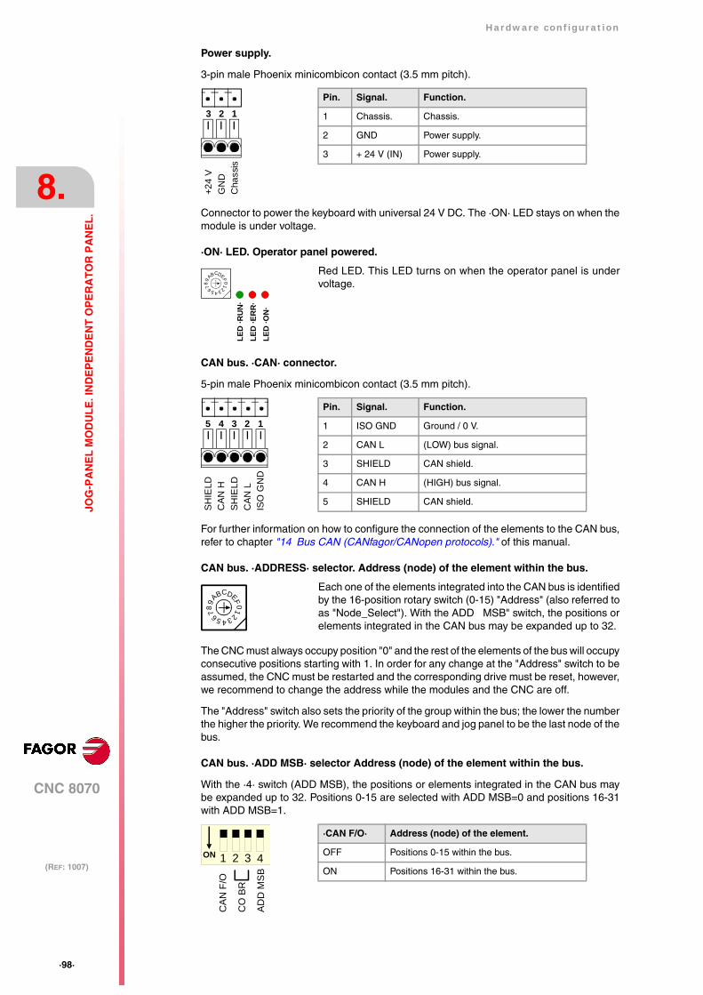
·98·
Hardware configuration
CNC 8070
8.
(REF: 1007)
JOG
-PA
NE
L M
OD
UL
E. I
ND
EP
EN
DE
NT
OP
ER
AT
OR
PA
NE
L.
Power supply.
3-pin male Phoenix minicombicon contact (3.5 mm pitch).
Connector to power the keyboard with universal 24 V DC. The ·ON· LED stays on when themodule is under voltage.
·ON· LED. Operator panel powered.
CAN bus. ·CAN· connector.
5-pin male Phoenix minicombicon contact (3.5 mm pitch).
For further information on how to configure the connection of the elements to the CAN bus,refer to chapter "14 Bus CAN (CANfagor/CANopen protocols)." of this manual.
CAN bus. ·ADDRESS· selector. Address (node) of the element within the bus.
The CNC must always occupy position "0" and the rest of the elements of the bus will occupyconsecutive positions starting with 1. In order for any change at the "Address" switch to beassumed, the CNC must be restarted and the corresponding drive must be reset, however,we recommend to change the address while the modules and the CNC are off.
The "Address" switch also sets the priority of the group within the bus; the lower the numberthe higher the priority. We recommend the keyboard and jog panel to be the last node of thebus.
CAN bus. ·ADD MSB· selector Address (node) of the element within the bus.
With the ·4· switch (ADD MSB), the positions or elements integrated in the CAN bus maybe expanded up to 32. Positions 0-15 are selected with ADD MSB=0 and positions 16-31with ADD MSB=1.
Red LED. This LED turns on when the operator panel is undervoltage.
Each one of the elements integrated into the CAN bus is identifiedby the 16-position rotary switch (0-15) "Address" (also referred toas "Node_Select"). With the ADD MSB" switch, the positions orelements integrated in the CAN bus may be expanded up to 32.
Pin. Signal. Function.
1 Chassis. Chassis.
2 GND Power supply.
3 + 24 V (IN) Power supply.
+24
VG
ND
Cha
ssis
123
LED
·RU
N·
LED
·ER
R·
LED
·ON
·
4
01
FEDCBA98 7 6 5 32
Pin. Signal. Function.
1 ISO GND Ground / 0 V.
2 CAN L (LOW) bus signal.
3 SHIELD CAN shield.
4 CAN H (HIGH) bus signal.
5 SHIELD CAN shield.
12345
ISO
GN
DC
AN
LSH
IELD
CA
N H
SHIE
LD
4
01FE
DCBA98 7 6 5 32
·CAN F/O· Address (node) of the element.
OFF Positions 0-15 within the bus.
ON Positions 16-31 within the bus.1 2 3 4ON
CAN
F/O
CO
BR
AD
D M
SB

Hardware configuration
CNC 8070
8.
(REF: 1007)
·99·
JOG
-PA
NE
L M
OD
UL
E. I
ND
EP
EN
DE
NT
OP
ER
AT
OR
PA
NE
L.
CAN bus. ·ST· selector.
The switch position of the terminating elements must be "1" and that of the rest of theelements "0".
CAN bus. Bus type selector: CANfagor / CANopen.
Switch ·1· (CAN F/O) selects the type of CAN bus to by used, i.e. CANfagor or CANOpen.
CAN bus. Selecting the baudrate for the CANopen bus.
When using the CANopen protocol, the transmission speed at the bus is defined in each nodeand they all must run at the same speed. The speed is selected with switches ·2· and ·3·(CO BR).
The transmission speed depends on the total length of the bus. Using the following illustrativevalues; assigning other values may cause communication errors due to signal distortion.
In order for any change of speed to be assumed, the corresponding module must be reset;however, we recommend to change the speed while the modules and the CNC are off.
Led ·ERR·. Status indicator LED.
Red LED. Its meaning depends on the blinking speed.
Led ·RUN·. Status indicator LED.
The LED is green. Its meaning depends on the blinking speed.
Line terminating resistor. The ·LT· switch identifies which are theelements that occupy the ends of the CAN bus; i.e. the first and lastphysical element in the connection.0 1
·CAN F/O· Type of CAN bus.
OFF The CANfagor bus has been selected.
ON The CANopen bus has been selected.1 2 3 4ON
CAN
F/O
CO
BR
AD
D M
SB
·CO BR· Speed Length of the CAN bus.
1000 kHz Up to 20 meters.
800 kHz From 20 to 40 meters.
500 kHz From 40 to 100 meters.
250 kHz From 100 to 500 meters.
2 3
OFFON
2 3
OFFON
2 3
OFFON
2 3ONOFF
1 2 3 4ON
CAN
F/O
CO
BR
AD
D M
SB
Type of blinking. Meaning
LED off. The module works properly.
Blinking fast. Module configuration stage.
Single blinking. Warning. Poor transmission.
Double blinking. There is no communication with the cpu.
LED on. Error. Too many errors.
LED
·RU
N·
LED
·ER
R·
LED
·ON
·
4
01
FEDCBA98 7 6 5 32
Type of blinking. Meaning
LED on. The module works properly.
Single blinking. Module stopped.
Blinking fast. Module configuration stage.
Continuous blinking. Start-up stage or error.
LED
·RU
N·
LED
·ER
R·
LED
·ON
·
4
01
FEDCBA98 7 6 5 32
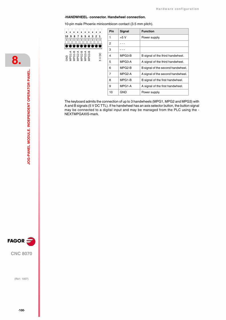
·100·
Hardware configuration
CNC 8070
8.
(REF: 1007)
JOG
-PA
NE
L M
OD
UL
E. I
ND
EP
EN
DE
NT
OP
ER
AT
OR
PA
NE
L.
·HANDWHEEL· connector. Handwheel connection.
10-pin male Phoenix minicombicon contact (3.5 mm pitch).
The keyboard admits the connection of up to 3 handwheels (MPG1, MPG2 and MPG3) withA and B signals (5 V DC TTL). If he handwheel has an axis selector button, the button signalmay be connected to a digital input and may be managed from the PLC using the -NEXTMPGAXIS-mark.
Pin Signal Function
1 +5 V Power supply.
2 - - -
3 - - -
4 MPG3-B B signal of the third handwheel.
5 MPG3-A A signal of the third handwheel.
6 MPG2-B B signal of the second handwheel.
7 MPG2-A A signal of the second handwheel.
8 MPG1-B B signal of the first handwheel.
9 MPG1-A A signal of the first handwheel.
10 GND Power supply.
789 3456 1210
MPG
2-B
MPG
2-A
MPG
1-B
MPG
1-A
GN
D
MPG
3-B
MPG
3-A
5 V
DC

Hardware configuration
CNC 8070
9.
(REF: 1007)
·101·
MO
US
E M
OD
UL
E.
9 MOUSE MODULE.
9.1 Hardware dimensions.
General characteristics.
Connection. Connection to the central unit through PS-2 connector.
mm inchDa 117 4,61Db 61 2,40Dc 4,5 0,18Ø 4,5 0,18
mm incha 126 4,96b 70 2,76c 10,2 0,40
a
b
Da
Db
Ø
Dc
Dc
c
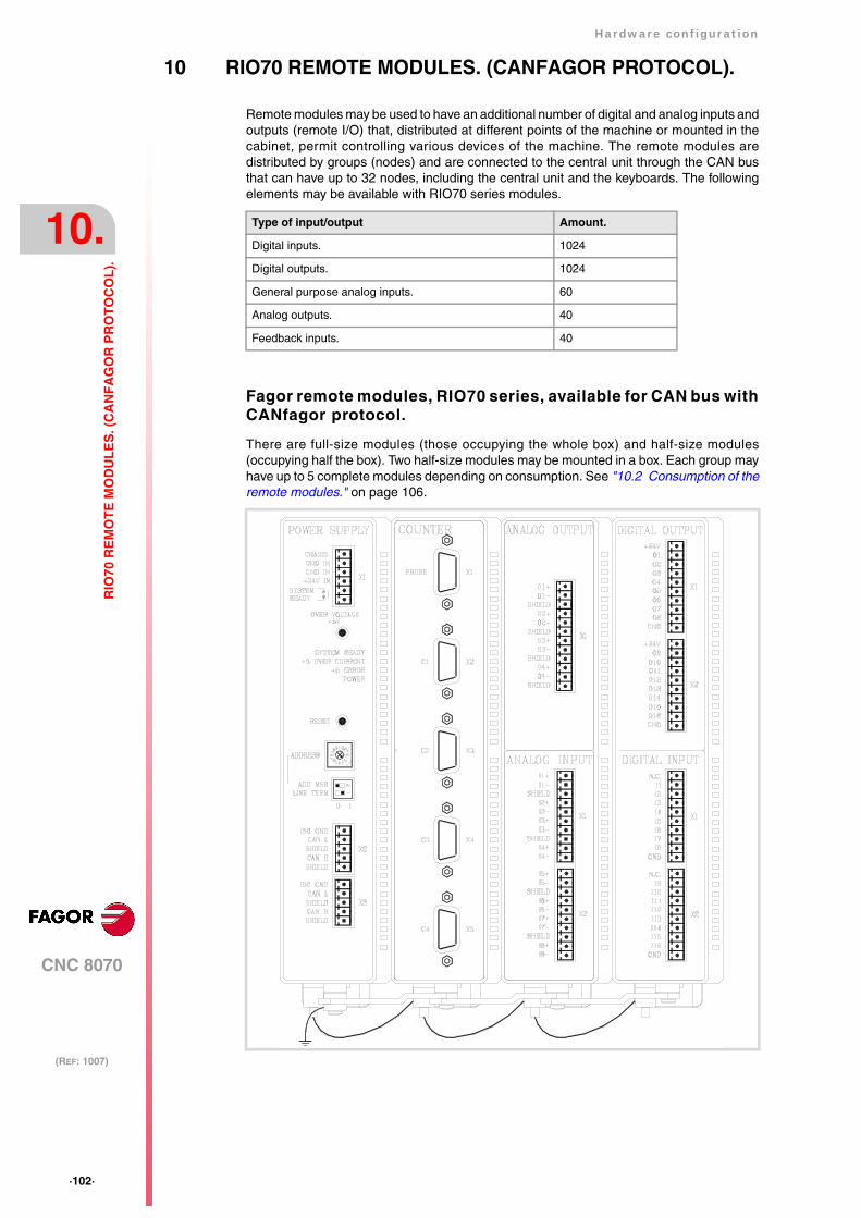
·102·
Hardware configuration
CNC 8070
10.
(REF: 1007)
RIO
70 R
EM
OT
E M
OD
UL
ES
. (C
AN
FA
GO
R P
RO
TO
CO
L).
10 RIO70 REMOTE MODULES. (CANFAGOR PROTOCOL).
Remote modules may be used to have an additional number of digital and analog inputs andoutputs (remote I/O) that, distributed at different points of the machine or mounted in thecabinet, permit controlling various devices of the machine. The remote modules aredistributed by groups (nodes) and are connected to the central unit through the CAN busthat can have up to 32 nodes, including the central unit and the keyboards. The followingelements may be available with RIO70 series modules.
Fagor remote modules, RIO70 series, available for CAN bus withCANfagor protocol.
There are full-size modules (those occupying the whole box) and half-size modules(occupying half the box). Two half-size modules may be mounted in a box. Each group mayhave up to 5 complete modules depending on consumption. See "10.2 Consumption of theremote modules." on page 106.
Type of input/output Amount.
Digital inputs. 1024
Digital outputs. 1024
General purpose analog inputs. 60
Analog outputs. 40
Feedback inputs. 40

Hardware configuration
CNC 8070
10.
(REF: 1007)
·103·
RIO
70 R
EM
OT
E M
OD
UL
ES
. (C
AN
FA
GO
R P
RO
TO
CO
L).
Fagor supplies all types of possible combinations with half-size modules, even units with asingle half-size module (the other half will be a cover). The available modules are thefollowing.
• Power supply.
The power supply module must be present in each group. This module must be poweredat 24 V DC and connected to the system CAN bus.
• Feedback inputs.
Each module has 4 feedback inputs.
• Digital inputs. Half size.
Each module has 16 digital inputs.
• Digital outputs. Half size.
Each module has 16 digital outputs.
• Analog inputs. Half size.
Each module has 8 analog inputs.
• Analog outputs. Half size.
Each module has 4 analog outputs.
Probe connection.
The digital inputs let you handle the signal of the two 24 V DC probes . Use machineparameters to define which digital input is associated with each probe and their type of pulse.

·104·
Hardware configuration
CNC 8070
10.
(REF: 1007)
RIO
70 R
EM
OT
E M
OD
UL
ES
. (C
AN
FA
GO
R P
RO
TO
CO
L).
10.1 Dimensions and mounting of the modules.
Place the modules on 2 profiles, according to the UNE 50022 standard, with 2 securing ends,one at each end of the group; they help securing the modules besides maintaining the rightgap between the profiles. The mounting order to be followed from left to right is:
• Power Supply.
• Counters.
• Analog outputs. Half size.
• Analog inputs. Half size.
• Digital outputs. Half size.
• Digital inputs. Half size.
Dimensions of the modules.
Always leave a 140 mm gap under the modules for ventilation and later handling.
Connection of the modules.
The modules of the group are connected as follows:
A For ground connection.
B Ribbon cable to interconnect the modules.
C Securing ends.

Hardware configuration
CNC 8070
10.
(REF: 1007)
·105·
RIO
70 R
EM
OT
E M
OD
UL
ES
. (C
AN
FA
GO
R P
RO
TO
CO
L).
Each group is connected to the system (CPU, Keyboard, etc.) through the CAN bus asdescribed later on.
DO NOT make any connection or connect any module to the power supply while the latter is turnedon. Before making any connection, ribbon cable included, turn the power supply off by unplugging thepower cable.
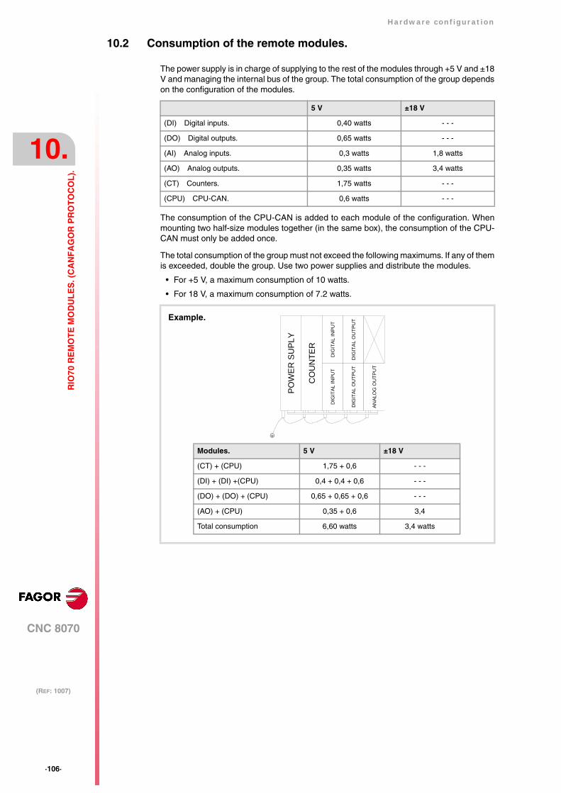
·106·
Hardware configuration
CNC 8070
10.
(REF: 1007)
RIO
70 R
EM
OT
E M
OD
UL
ES
. (C
AN
FA
GO
R P
RO
TO
CO
L).
10.2 Consumption of the remote modules.
The power supply is in charge of supplying to the rest of the modules through +5 V and ±18V and managing the internal bus of the group. The total consumption of the group dependson the configuration of the modules.
The consumption of the CPU-CAN is added to each module of the configuration. Whenmounting two half-size modules together (in the same box), the consumption of the CPU-CAN must only be added once.
The total consumption of the group must not exceed the following maximums. If any of themis exceeded, double the group. Use two power supplies and distribute the modules.
• For +5 V, a maximum consumption of 10 watts.
• For 18 V, a maximum consumption of 7.2 watts.
5 V ±18 V
(DI) Digital inputs. 0,40 watts - - -
(DO) Digital outputs. 0,65 watts - - -
(AI) Analog inputs. 0,3 watts 1,8 watts
(AO) Analog outputs. 0,35 watts 3,4 watts
(CT) Counters. 1,75 watts - - -
(CPU) CPU-CAN. 0,6 watts - - -
Modules. 5 V ±18 V
(CT) + (CPU) 1,75 + 0,6 - - -
(DI) + (DI) +(CPU) 0,4 + 0,4 + 0,6 - - -
(DO) + (DO) + (CPU) 0,65 + 0,65 + 0,6 - - -
(AO) + (CPU) 0,35 + 0,6 3,4
Total consumption 6,60 watts 3,4 watts
CO
UN
TER
DIG
ITAL
INPU
T
POW
ER
SU
PLY
DIG
ITA
L O
UTP
UT
DIG
ITA
L O
UTP
UT
DIG
ITA
L IN
PU
T
ANA
LOG
OU
TPU
T
Example.
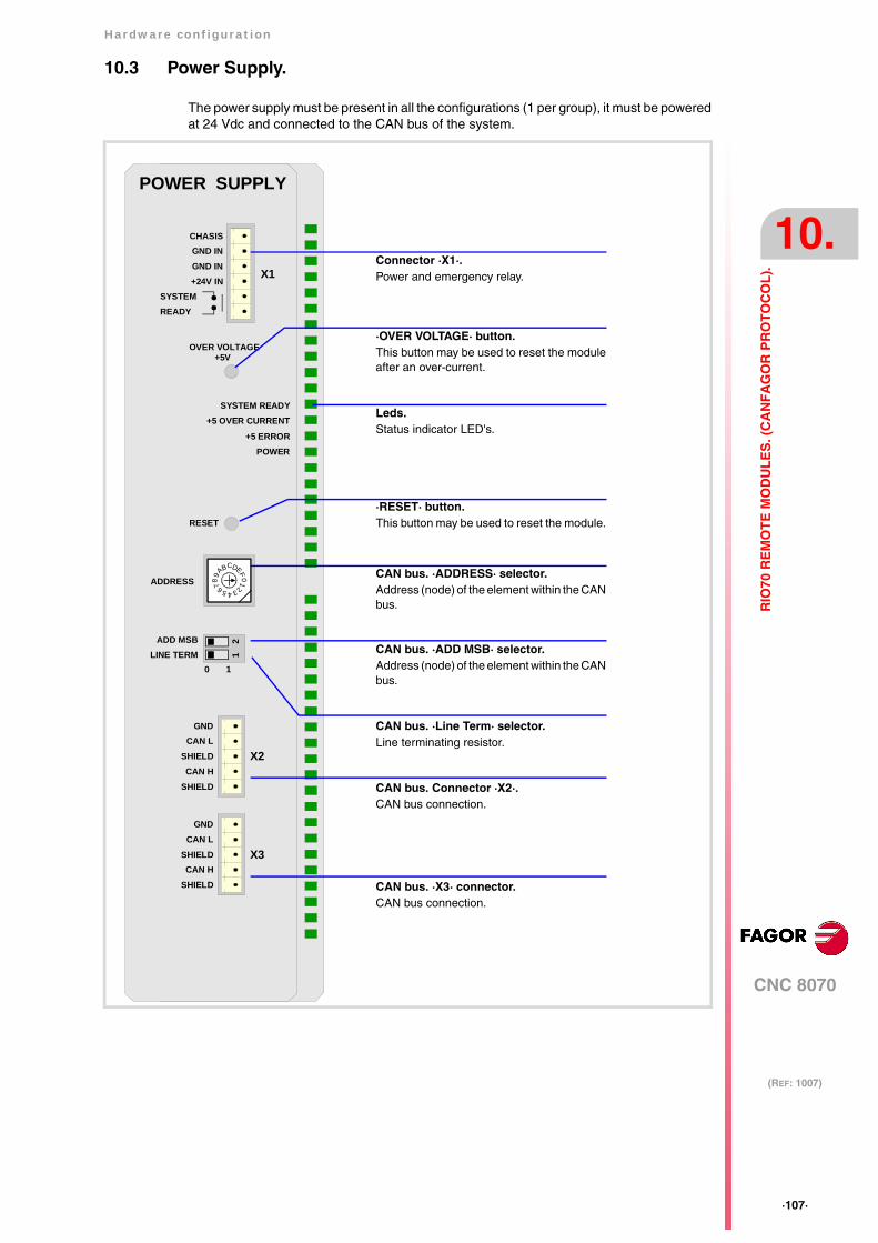
Hardware configuration
CNC 8070
10.
(REF: 1007)
·107·
RIO
70 R
EM
OT
E M
OD
UL
ES
. (C
AN
FA
GO
R P
RO
TO
CO
L).
10.3 Power Supply.
The power supply must be present in all the configurations (1 per group), it must be poweredat 24 Vdc and connected to the CAN bus of the system.
CAN bus. ·Line Term· selector.Line terminating resistor.
CAN bus. Connector ·X2·.CAN bus connection.
CAN bus. ·X3· connector.CAN bus connection.
GNDCAN L
SHIELD
SHIELDCAN H
X3
GNDCAN L
SHIELD
SHIELDCAN H
X2
POWER SUPPLY
4
01FEDCBA98 7 6 5 32
ADD MSBLINE TERM
10
12
ADDRESS
RESET
POWER
SYSTEM READY
+5 ERROR
+5 OVER CURRENT
OVER VOLTAGE+5V
X1
GND INCHASIS
GND IN+24V IN
SYSTEMREADY
CAN bus. ·ADD MSB· selector.Address (node) of the element within the CANbus.
CAN bus. ·ADDRESS· selector.Address (node) of the element within the CANbus.
·RESET· button.This button may be used to reset the module.
Leds.Status indicator LED's.
·OVER VOLTAGE· button.This button may be used to reset the moduleafter an over-current.
Connector ·X1·.Power and emergency relay.

·108·
Hardware configuration
CNC 8070
10.
(REF: 1007)
RIO
70 R
EM
OT
E M
OD
UL
ES
. (C
AN
FA
GO
R P
RO
TO
CO
L).
10.3.1 Elements (connectors).
Connector ·X1·. Power and emergency relay.
6-pin male Phoenix minicombicon contact (3.5 mm pitch).
The relay may be used to connect the modules to the emergency chain of the electricalcabinet. The relay is an internal contact that closes when the group is ready; it opens againwhen an internal failure occurs.
·OVER VOLTAGE· button and status LED.
This button may be used to reactivate the power supply after an over-current. An over-currentactivates the safety device inside the power supply turns on the external red LED. The powersupply will not be operative while the LED is on. There are two ways to reactivate the powersupply after an over-current.
• Unplug the power supply from mains and wait for about 30 seconds until the red lightturns off.
• Unplug the power supply and press the button. The red LED will turn off indicating thatthe power supply is ready.
If after reactivating the power supply, the LED turns back on, call the Technical ServiceDepartment.
·SYSTEM READY· LED. Module under power.
·OVER CURRENT· LED. Over-current at the power supply.
·ERROR· LED. Error at the power supply.
·POWER· LED. Status of the 5 V.
·RESET· button.
The ·RESET· button may be used to reset the module after changing the node address;however, it is recommended to change the address while the modules and the CNC are off.
The LED is green. This LED blinks when the module is underpower.
Red LED. This LED turns on when the +5 V power supply isoutputting the maximum current.
Red LED. This LED turns on when the power supply is not capableof supplying the 5 V DC due to a current overload
To eliminate the error, remove the load from the power supply orduplicate the group.
The LED is green. This LED turns on when the +5 V power supplyis working properly.
Signal. Function.
Chassis Shield.
GND IN Power input.
GND IN Power input.
+ 24 V Power input.
Sys temReady
Relay for the emergency chain.
654321
SYSTEMREADY
+24 V INGND INGND IN
CHASSIS
POWER+ 5 ERROR
+5 OVER CURRENTSYSTEM READY
POWER+ 5 ERROR
+5 OVER CURRENTSYSTEM READY
POWER+ 5 ERROR
+5 OVER CURRENTSYSTEM READY
POWER+ 5 ERROR
+5 OVER CURRENTSYSTEM READY
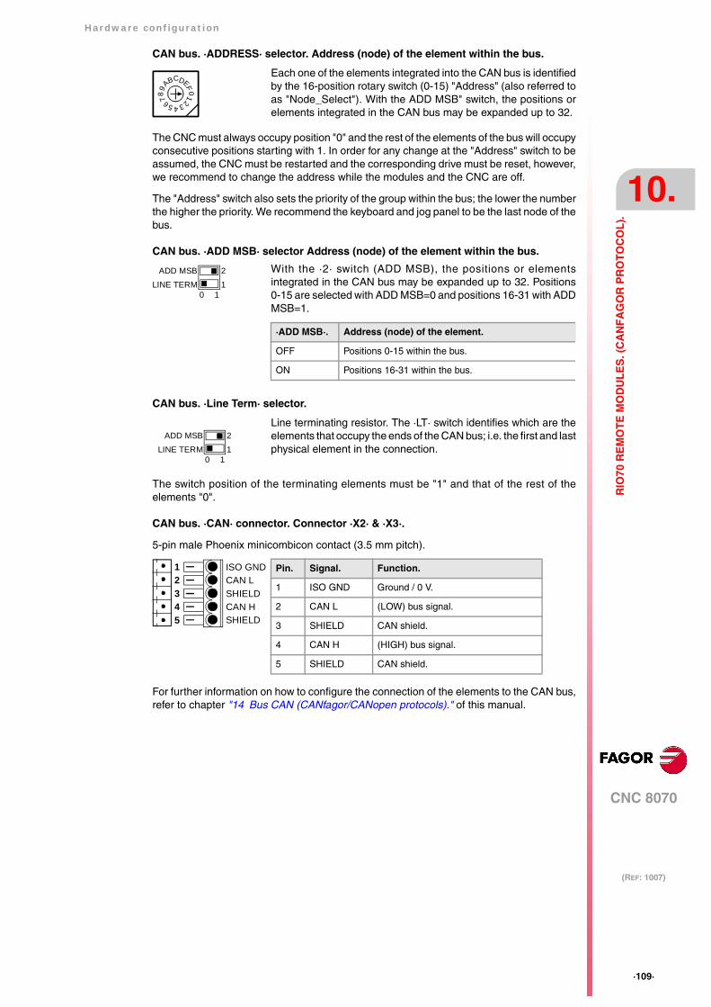
Hardware configuration
CNC 8070
10.
(REF: 1007)
·109·
RIO
70 R
EM
OT
E M
OD
UL
ES
. (C
AN
FA
GO
R P
RO
TO
CO
L).
CAN bus. ·ADDRESS· selector. Address (node) of the element within the bus.
The CNC must always occupy position "0" and the rest of the elements of the bus will occupyconsecutive positions starting with 1. In order for any change at the "Address" switch to beassumed, the CNC must be restarted and the corresponding drive must be reset, however,we recommend to change the address while the modules and the CNC are off.
The "Address" switch also sets the priority of the group within the bus; the lower the numberthe higher the priority. We recommend the keyboard and jog panel to be the last node of thebus.
CAN bus. ·ADD MSB· selector Address (node) of the element within the bus.
CAN bus. ·Line Term· selector.
The switch position of the terminating elements must be "1" and that of the rest of theelements "0".
CAN bus. ·CAN· connector. Connector ·X2· & ·X3·.
5-pin male Phoenix minicombicon contact (3.5 mm pitch).
For further information on how to configure the connection of the elements to the CAN bus,refer to chapter "14 Bus CAN (CANfagor/CANopen protocols)." of this manual.
Each one of the elements integrated into the CAN bus is identifiedby the 16-position rotary switch (0-15) "Address" (also referred toas "Node_Select"). With the ADD MSB" switch, the positions orelements integrated in the CAN bus may be expanded up to 32.
Line terminating resistor. The ·LT· switch identifies which are theelements that occupy the ends of the CAN bus; i.e. the first and lastphysical element in the connection.
4
01FE
DCBA98 7 6 5 32
With the ·2· switch (ADD MSB), the positions or elementsintegrated in the CAN bus may be expanded up to 32. Positions0-15 are selected with ADD MSB=0 and positions 16-31 with ADDMSB=1.
·ADD MSB·. Address (node) of the element.
OFF Positions 0-15 within the bus.
ON Positions 16-31 within the bus.
21
ADD MSBLINE TERM
0 1
21
ADD MSBLINE TERM
0 1
Pin. Signal. Function.
1 ISO GND Ground / 0 V.
2 CAN L (LOW) bus signal.
3 SHIELD CAN shield.
4 CAN H (HIGH) bus signal.
5 SHIELD CAN shield.
SHIELDCAN HSHIELDCAN LISO GND
54321
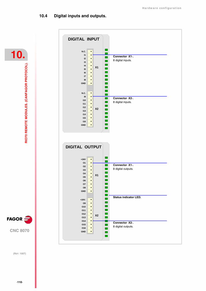
·110·
Hardware configuration
CNC 8070
10.
(REF: 1007)
RIO
70 R
EM
OT
E M
OD
UL
ES
. (C
AN
FA
GO
R P
RO
TO
CO
L).
10.4 Digital inputs and outputs.
DIGITAL OUTPUT
X1
X2
GNDO8
O1+24V
O2O3O4O5O6O7
GNDO16
O9+24V.
O10O11O12O13O14O15
DIGITAL INPUT
X1
X2
GNDI8
I1N.C.
I2I3I4I5I6I7
GNDI16
I9N.C.
I10I11I12I13I14I15
Connector ·X1·.8 digital inputs.
Connector ·X2·.8 digital inputs.
Connector ·X1·.8 digital outputs.
Status indicator LED.
Connector ·X2·.8 digital outputs.
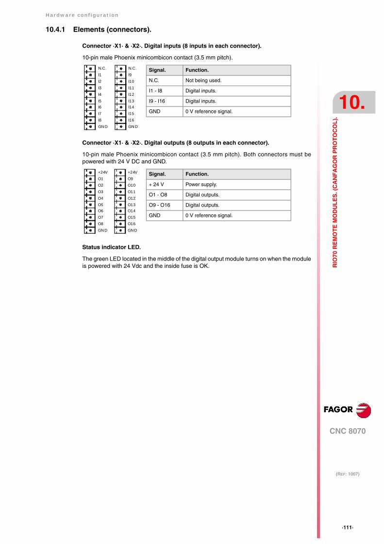
Hardware configuration
CNC 8070
10.
(REF: 1007)
·111·
RIO
70 R
EM
OT
E M
OD
UL
ES
. (C
AN
FA
GO
R P
RO
TO
CO
L).
10.4.1 Elements (connectors).
Connector ·X1· & ·X2·. Digital inputs (8 inputs in each connector).
10-pin male Phoenix minicombicon contact (3.5 mm pitch).
Connector ·X1· & ·X2·. Digital outputs (8 outputs in each connector).
10-pin male Phoenix minicombicon contact (3.5 mm pitch). Both connectors must bepowered with 24 V DC and GND.
Status indicator LED.
The green LED located in the middle of the digital output module turns on when the moduleis powered with 24 Vdc and the inside fuse is OK.
Signal. Function.
N.C. Not being used.
I1 - I8 Digital inputs.
I9 - I16 Digital inputs.
GND 0 V reference signal.
I1N.C.
GN DI8
I2I3I4I5I6I7
I9N.C.
GN DI16
I10I11I12I13I14I15
Signal. Function.
+ 24 V Power supply.
O1 - O8 Digital outputs.
O9 - O16 Digital outputs.
GND 0 V reference signal.
O1+24V
GN DO8
O2O3O4O5O6O7
O9+24V
GN DO16
O10O11O12O13O14O15
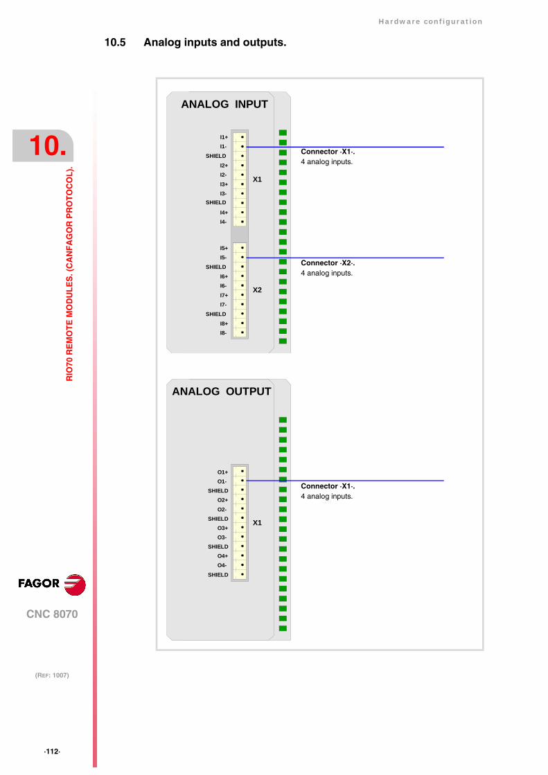
·112·
Hardware configuration
CNC 8070
10.
(REF: 1007)
RIO
70 R
EM
OT
E M
OD
UL
ES
. (C
AN
FA
GO
R P
RO
TO
CO
L).
10.5 Analog inputs and outputs.
ANALOG OUTPUT
X1
O1+O1-
SHIELDO2+O2-
SHIELDO3+O3-
SHIELDO4+O4-
SHIELD
ANALOG INPUT
X1
X2
I4-I4+
I1-I1+
SHIELDI2+I2-I3+I3-
SHIELD
I8-I8+
I5-I5+
SHIELDI6+I6-I7+I7-
SHIELD
Connector ·X1·.4 analog inputs.
Connector ·X2·.4 analog inputs.
Connector ·X1·.4 analog inputs.
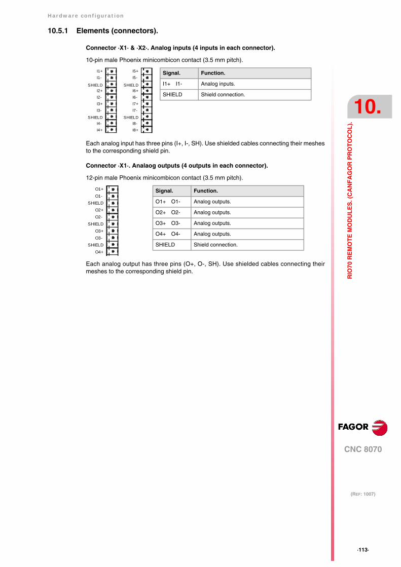
Hardware configuration
CNC 8070
10.
(REF: 1007)
·113·
RIO
70 R
EM
OT
E M
OD
UL
ES
. (C
AN
FA
GO
R P
RO
TO
CO
L).
10.5.1 Elements (connectors).
Connector ·X1· & ·X2·. Analog inputs (4 inputs in each connector).
10-pin male Phoenix minicombicon contact (3.5 mm pitch).
Each analog input has three pins (I+, I-, SH). Use shielded cables connecting their meshesto the corresponding shield pin.
Connector ·X1·. Analaog outputs (4 outputs in each connector).
12-pin male Phoenix minicombicon contact (3.5 mm pitch).
Each analog output has three pins (O+, O-, SH). Use shielded cables connecting theirmeshes to the corresponding shield pin.
I1+I1-
SHIELDI2+I2-I3+I3-
SHIELDI4-I4+
I5+I5-
SHIELDI6+I6-I7+I7-
SHIELDI8-I8+
Signal. Function.
I1+ I1- Analog inputs.
SHIELD Shield connection.
Signal. Function.
O1+ O1- Analog outputs.
O2+ O2- Analog outputs.
O3+ O3- Analog outputs.
O4+ O4- Analog outputs.
SHIELD Shield connection.
O1+O1-
SHIELDO2+O2-
SHIELDO3+O3-
SHIELDO4+
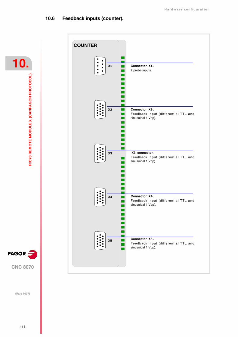
·114·
Hardware configuration
CNC 8070
10.
(REF: 1007)
RIO
70 R
EM
OT
E M
OD
UL
ES
. (C
AN
FA
GO
R P
RO
TO
CO
L).
10.6 Feedback inputs (counter).
COUNTER
X1
X2
X3
X4
X5
Connector ·X1·.2 probe inputs.
Connector ·X2·.Feedback input (d i f ferent ia l TTL andsinusoidal 1 Vpp).
·X3· connector.Feedback input (d i f ferent ia l TTL andsinusoidal 1 Vpp).
Connector ·X4·.Feedback input (d i f ferent ia l TTL andsinusoidal 1 Vpp).
Connector ·X5·.Feedback input (d i f ferent ia l TTL andsinusoidal 1 Vpp).

Hardware configuration
CNC 8070
10.
(REF: 1007)
·115·
RIO
70 R
EM
OT
E M
OD
UL
ES
. (C
AN
FA
GO
R P
RO
TO
CO
L).
10.6.1 Elements (connectors).
Connector ·X1·.
Not being used from software version V01.10 on. Previous versions allowed connecting 2probes of 5 V DC or 24 V DC.
Connectors ·X2· & ·X3· & ·X4· & ·X5·. Feedback inputs (differential TTL and sinusoidal1 Vpp).
4 15-pin female SUB-D HD type connectors.
To connect feedback devices with differential TTL or 1 Vpp sinusoidal signals. See"10.8 Feedback inputs. Technical characteristics and connection." on page 117.
(*) Pin ·15· is offered for compatibility. We recommed to connect the cableshield to the connector housing at both ends.
Pin. Signal. Function.
1 A Feedback signals.
2 / A
3 B
4 / B
5 I0 Reference signals.
6 / I0
7 AL Feedback alarm.
8 / AL
9 +5 Vdc Voltage supply for the feedback system.
10 - - -
11 GND 0 V reference signal.
12 - - -
13 - - -
14 - - -
15 Chassis(*) Shield.
11
15
6
10
1
5
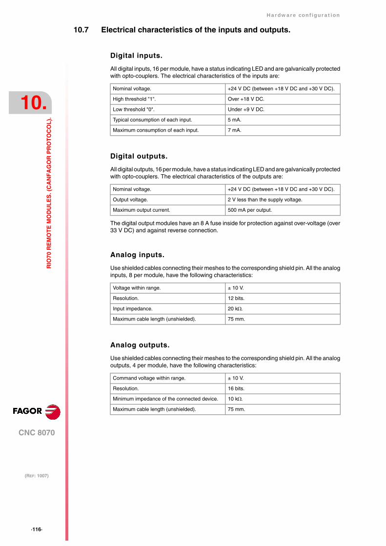
·116·
Hardware configuration
CNC 8070
10.
(REF: 1007)
RIO
70 R
EM
OT
E M
OD
UL
ES
. (C
AN
FA
GO
R P
RO
TO
CO
L).
10.7 Electrical characteristics of the inputs and outputs.
Digital inputs.
All digital inputs, 16 per module, have a status indicating LED and are galvanically protectedwith opto-couplers. The electrical characteristics of the inputs are:
Digital outputs.
All digital outputs, 16 per module, have a status indicating LED and are galvanically protectedwith opto-couplers. The electrical characteristics of the outputs are:
The digital output modules have an 8 A fuse inside for protection against over-voltage (over33 V DC) and against reverse connection.
Analog inputs.
Use shielded cables connecting their meshes to the corresponding shield pin. All the analoginputs, 8 per module, have the following characteristics:
Analog outputs.
Use shielded cables connecting their meshes to the corresponding shield pin. All the analogoutputs, 4 per module, have the following characteristics:
Nominal voltage. +24 V DC (between +18 V DC and +30 V DC).
High threshold "1". Over +18 V DC.
Low threshold "0". Under +9 V DC.
Typical consumption of each input. 5 mA.
Maximum consumption of each input. 7 mA.
Nominal voltage. +24 V DC (between +18 V DC and +30 V DC).
Output voltage. 2 V less than the supply voltage.
Maximum output current. 500 mA per output.
Voltage within range. ± 10 V.
Resolution. 12 bits.
Input impedance. 20 kΩ.
Maximum cable length (unshielded). 75 mm.
Command voltage within range. ± 10 V.
Resolution. 16 bits.
Minimum impedance of the connected device. 10 kΩ.
Maximum cable length (unshielded). 75 mm.
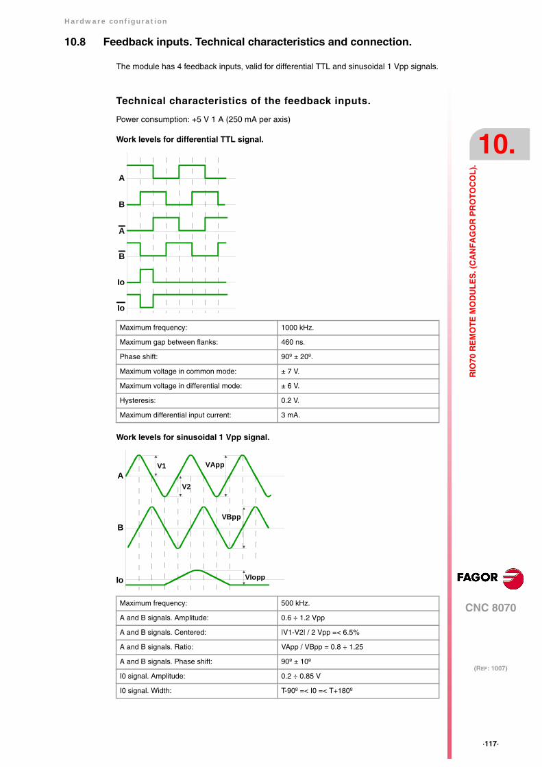
Hardware configuration
CNC 8070
10.
(REF: 1007)
·117·
RIO
70 R
EM
OT
E M
OD
UL
ES
. (C
AN
FA
GO
R P
RO
TO
CO
L).
10.8 Feedback inputs. Technical characteristics and connection.
The module has 4 feedback inputs, valid for differential TTL and sinusoidal 1 Vpp signals.
Technical characteristics of the feedback inputs.
Power consumption: +5 V 1 A (250 mA per axis)
Work levels for differential TTL signal.
Work levels for sinusoidal 1 Vpp signal.
Maximum frequency: 1000 kHz.
Maximum gap between flanks: 460 ns.
Phase shift: 90º ± 20º.
Maximum voltage in common mode: ± 7 V.
Maximum voltage in differential mode: ± 6 V.
Hysteresis: 0.2 V.
Maximum differential input current: 3 mA.
Maximum frequency: 500 kHz.
A and B signals. Amplitude: 0.6 ÷ 1.2 Vpp
A and B signals. Centered: |V1-V2| / 2 Vpp =< 6.5%
A and B signals. Ratio: VApp / VBpp = 0.8 ÷ 1.25
A and B signals. Phase shift: 90º ± 10º
I0 signal. Amplitude: 0.2 ÷ 0.85 V
I0 signal. Width: T-90º =< I0 =< T+180º
A
B
Io
A
B
Io
A
B
Io
V1
V2
VApp
VBpp
VIopp
·118·
Hardware configuration
CNC 8070
10.
(REF: 1007)
RIO
70 R
EM
OT
E M
OD
UL
ES
. (C
AN
FA
GO
R P
RO
TO
CO
L).
Feedback cable characteristics.
The cable used must have overall shield; the rest of the characteristics of the cable, as wellas its length, will depend on the type of feedback device used. Refer to our catalog.
The shield of the cable being used must be connected to the connector housing at both ends.The unshielded portion of the wires of an unshielded cable cannot be longer than 75 mm.
We recommend to run the feedback cables as far away as possible from the power cablesof the machine.
Fagor Automation offers a wide range of cables and extension cables to connect the feedback systemsto the CNC. Refer to our catalog for further information.
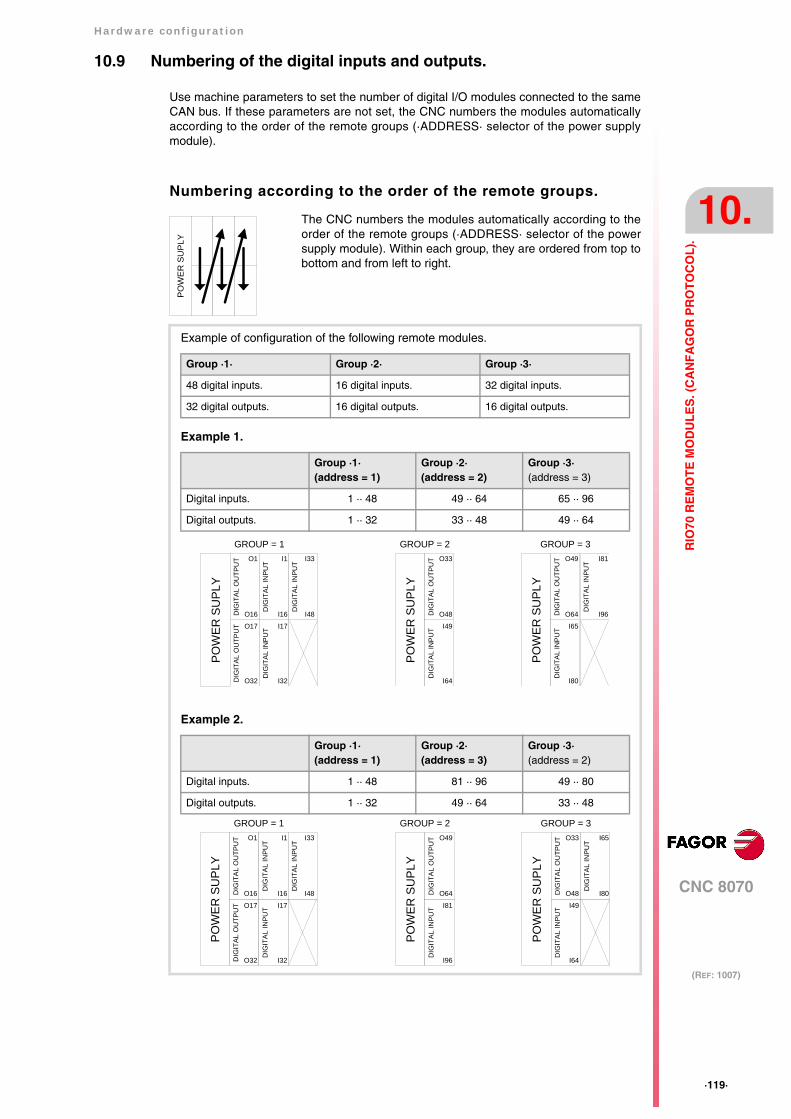
Hardware configuration
CNC 8070
10.
(REF: 1007)
·119·
RIO
70 R
EM
OT
E M
OD
UL
ES
. (C
AN
FA
GO
R P
RO
TO
CO
L).
10.9 Numbering of the digital inputs and outputs.
Use machine parameters to set the number of digital I/O modules connected to the sameCAN bus. If these parameters are not set, the CNC numbers the modules automaticallyaccording to the order of the remote groups (·ADDRESS· selector of the power supplymodule).
Numbering according to the order of the remote groups.
The CNC numbers the modules automatically according to theorder of the remote groups (·ADDRESS· selector of the powersupply module). Within each group, they are ordered from top tobottom and from left to right.
PO
WE
R S
UPL
Y
Example of configuration of the following remote modules.
Group ·1· Group ·2· Group ·3·
48 digital inputs. 16 digital inputs. 32 digital inputs.
32 digital outputs. 16 digital outputs. 16 digital outputs.
Example 1.
Group ·1·(address = 1)
Group ·2·(address = 2)
Group ·3·(address = 3)
Digital inputs. 1 ·· 48 49 ·· 64 65 ·· 96
Digital outputs. 1 ·· 32 33 ·· 48 49 ·· 64
Example 2.
Group ·1·(address = 1)
Group ·2·(address = 3)
Group ·3·(address = 2)
Digital inputs. 1 ·· 48 81 ·· 96 49 ·· 80
Digital outputs. 1 ·· 32 49 ·· 64 33 ·· 48
GROUP = 1
PO
WE
R S
UP
LYD
IGIT
AL
OU
TPU
T
O48
DIG
ITA
L IN
PU
T
O33
I64
I49
GROUP = 2
PO
WE
R S
UP
LYD
IGIT
AL
OU
TPU
T
DIG
ITAL
INPU
TD
IGIT
AL
INP
UT
O16
DIG
ITAL
OU
TPU
T
O1
O32
O17
DIG
ITAL
INPU
T
I48
I33
I16
I1
I32
I17
GROUP = 3P
OW
ER
SU
PLY
DIG
ITA
L O
UTP
UT
DIG
ITAL
INPU
T
O64
DIG
ITA
L IN
PU
TO49
I80
I65
I96
I81
GROUP = 1
PO
WE
R S
UP
LYD
IGIT
AL
OU
TPU
T
O64
DIG
ITA
L IN
PU
T
O49
I96
I81
GROUP = 2
PO
WE
R S
UP
LYD
IGIT
AL
OU
TPU
T
DIG
ITA
L IN
PUT
DIG
ITA
L IN
PU
T
O16
DIG
ITA
L O
UTP
UT
O1
O32
O17
DIG
ITA
L IN
PUT
I48
I33
I16
I1
I32
I17
GROUP = 3
PO
WE
R S
UP
LYD
IGIT
AL
OU
TPU
T
DIG
ITA
L IN
PUT
O48
DIG
ITA
L IN
PU
T
O33
I64
I49
I80
I65
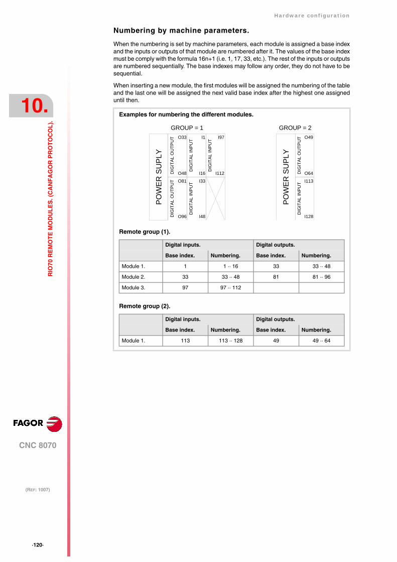
·120·
Hardware configuration
CNC 8070
10.
(REF: 1007)
RIO
70 R
EM
OT
E M
OD
UL
ES
. (C
AN
FA
GO
R P
RO
TO
CO
L).
Numbering by machine parameters.
When the numbering is set by machine parameters, each module is assigned a base indexand the inputs or outputs of that module are numbered after it. The values of the base indexmust be comply with the formula 16n+1 (i.e. 1, 17, 33, etc.). The rest of the inputs or outputsare numbered sequentially. The base indexes may follow any order, they do not have to besequential.
When inserting a new module, the first modules will be assigned the numbering of the tableand the last one will be assigned the next valid base index after the highest one assigneduntil then.
Examples for numbering the different modules.
Remote group (1).
Digital inputs. Digital outputs.
Base index. Numbering. Base index. Numbering.
Module 1. 1 1 ·· 16 33 33 ·· 48
Module 2. 33 33 ·· 48 81 81 ·· 96
Module 3. 97 97 ·· 112
Remote group (2).
Digital inputs. Digital outputs.
Base index. Numbering. Base index. Numbering.
Module 1. 113 113 ·· 128 49 49 ·· 64
GROUP = 1
PO
WE
R S
UPL
YD
IGIT
AL
OU
TPU
T
DIG
ITAL
INPU
TD
IGIT
AL IN
PUT
O48D
IGIT
AL
OU
TPU
T
O33
O96
O81
DIG
ITAL
INPU
T
I112
I97
I16
I1
I48
I33
GROUP = 2
PO
WE
R S
UPL
YD
IGIT
AL
OU
TPU
T
O64
DIG
ITAL
INPU
T
O49
I128
I113
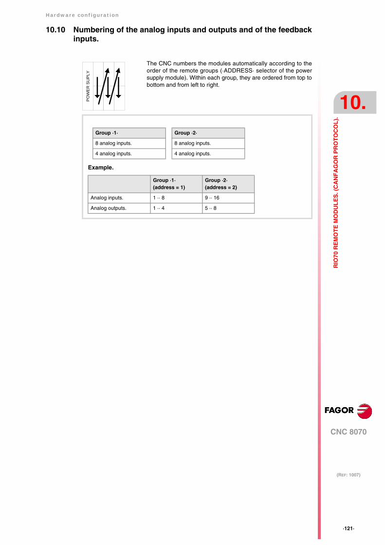
Hardware configuration
CNC 8070
10.
(REF: 1007)
·121·
RIO
70 R
EM
OT
E M
OD
UL
ES
. (C
AN
FA
GO
R P
RO
TO
CO
L).
10.10 Numbering of the analog inputs and outputs and of the feedbackinputs.
The CNC numbers the modules automatically according to theorder of the remote groups (·ADDRESS· selector of the powersupply module). Within each group, they are ordered from top tobottom and from left to right.
PO
WE
R S
UP
LY
Group ·1·
8 analog inputs.
4 analog inputs.
Example.
Group ·1·(address = 1)
Group ·2·(address = 2)
Analog inputs. 1 ·· 8 9 ·· 16
Analog outputs. 1 ·· 4 5 ·· 8
Group ·2·
8 analog inputs.
4 analog inputs.
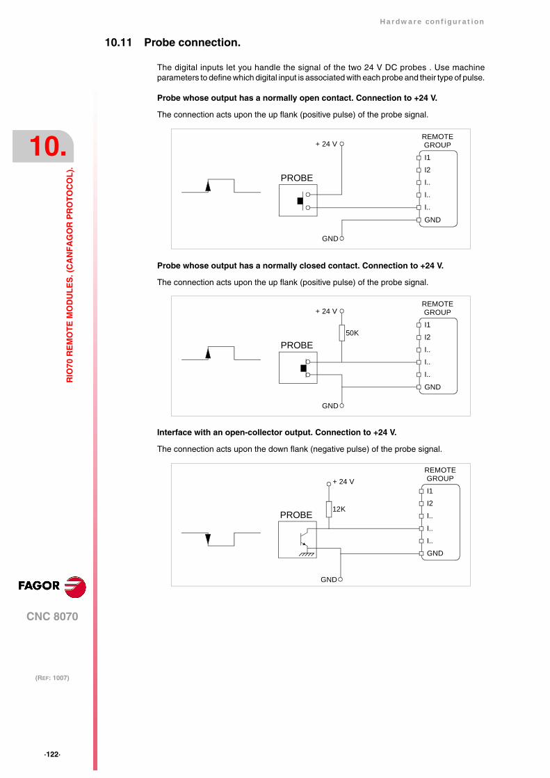
·122·
Hardware configuration
CNC 8070
10.
(REF: 1007)
RIO
70 R
EM
OT
E M
OD
UL
ES
. (C
AN
FA
GO
R P
RO
TO
CO
L).
10.11 Probe connection.
The digital inputs let you handle the signal of the two 24 V DC probes . Use machineparameters to define which digital input is associated with each probe and their type of pulse.
Probe whose output has a normally open contact. Connection to +24 V.
The connection acts upon the up flank (positive pulse) of the probe signal.
Probe whose output has a normally closed contact. Connection to +24 V.
The connection acts upon the up flank (positive pulse) of the probe signal.
Interface with an open-collector output. Connection to +24 V.
The connection acts upon the down flank (negative pulse) of the probe signal.
PROBE
I1
+ 24 V REMOTEGROUP
I2
I..
GND
I..
I..
GND
50K
PROBE
I1
+ 24 V REMOTEGROUP
I2
I..
GND
I..
I..
GND
PROBE 12K
+ 24 V I1
REMOTEGROUP
I2
I..
GND
I..
I..
GND
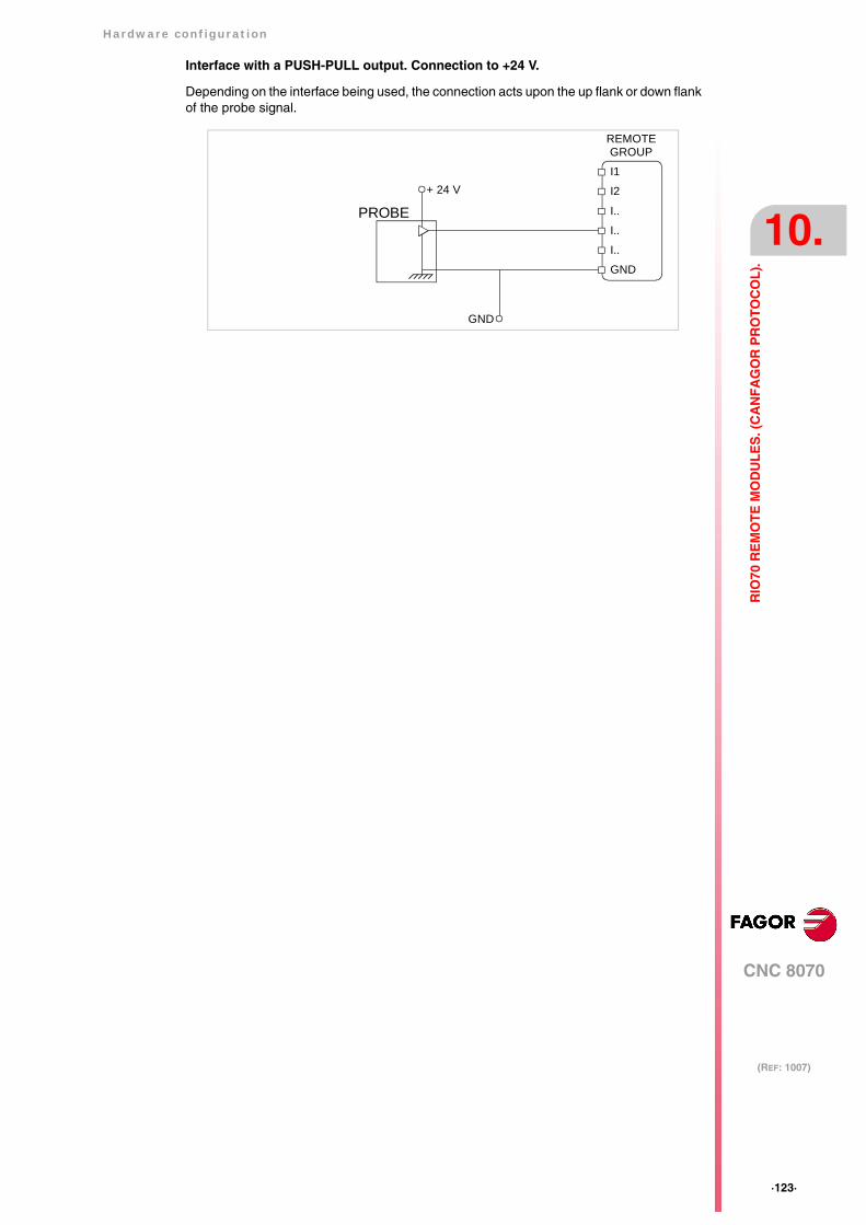
Hardware configuration
CNC 8070
10.
(REF: 1007)
·123·
RIO
70 R
EM
OT
E M
OD
UL
ES
. (C
AN
FA
GO
R P
RO
TO
CO
L).
Interface with a PUSH-PULL output. Connection to +24 V.
Depending on the interface being used, the connection acts upon the up flank or down flankof the probe signal.
PROBE + 24 V
I1
REMOTEGROUP
I2
I..
GND
I..
I..
GND

·124·
Hardware configuration
CNC 8070
11.
(REF: 1007)
RIO
5 R
EM
OT
E M
OD
UL
ES
. (C
AN
OP
EN
PR
OT
OC
OL
).
11 RIO5 REMOTE MODULES. (CANOPEN PROTOCOL).
Remote modules may be used to have an additional number of digital and analog inputs andoutputs (remote I/O) that, distributed at different points of the machine or mounted in thecabinet, permit controlling various devices of the machine. The remote modules aredistributed by groups (nodes) and are connected to the central unit through the CAN busthat can have up to 32 nodes, including the central unit and the keyboards. The followingelements may be available with RIO5 series modules.
When the CNC works with CANopen bus, this bus lets combine in the bus groups (nodes)formed by RIO5 and RIOW series modules; modules of both series cannot be combined inthe same group.
Fagor remote modules, RIO5 series, available for CAN bus withCANopen protocol.
Each group (node) may consist of up to two of these modules.
A Power supply with 24 digital inputs and 16 digital outputs.
B Power supply with 4 analog inputs, 4 analog outputs and 2 inputs for temperaturesensors.
C Digital Inputs / Outputs (single module). Each module has 24 digital inputs and 16 digitaloutputs.
D Digital Inputs / Outputs (double module). Each module has 48 digital inputs and 32 digitaloutputs.
Type of input/output Amount.
Digital inputs. 1024
Digital outputs. 1024
General purpose analog inputs. 40
Analog outputs. 40
Analog inputs for temperature sensors. 10
POWER 24I/16O
X1
CHS
GND
24V
SPEED10
ADDRESS
ERR
RUN
CAN
01
LT
GN DLSHHSH
GN DLSHHSH
X2
X3X7
I24
I13
X6
I12
I1
X5
GN DO16
O9+24V
O1+24V
X4
GN DO8
POWERANALOG I/O
X1
CHS
GN D
24V
SPEED10
ADDRESS
ERR
RUN
CAN
01
LT
GNDLSHHSH
GNDLSHHSH
X2
X3
0101
SH
X4
RL1R1R1RF1SH
X5
12I1I1SH
12GN D
X6
DIGITAL IN/OUT
X8
I24
I13
X7
I12
I1
X6
GN DO16
O9+24V
O1+24V
X5
GN DO8
X4
I24
I13
X3
I12
I1
X2
GN DO16
O9+24V
O1+24V
X1
GN DO8
DIGITAL IN/OUT
X4
I24
I13
X3
I12
I1
X2
GN DO16
O9+24V
O1+24V
X1
GN DO8
A B C D

Hardware configuration
CNC 8070
11.
(REF: 1007)
·125·
RIO
5 R
EM
OT
E M
OD
UL
ES
. (C
AN
OP
EN
PR
OT
OC
OL
).
General considerations on power supply modules.
When mounting the groups, bear in mind the following.
• One of the power supply modules must be present in each group. The power supply mustbe powered at 24 Vdc and connected to the CAN bus of the system.
• Two power supply modules cannot be in the same group.
• Power supplies of both models may be connected to the same CAN bus.
Fagor modules and third-party modules. Considerations aboutthe number of analog inputs.
The CANopen bus can manage up to 60 analog inputs of any kind. The maximum numberof analog inputs of each type that the bus can have depends on the type of modules installed.
CAN bus with Fagor modules.
A bus made up of only with Fagor modules can have 40 general purpose analog inputs and10 inputs for temperature sensors. In Fagor modules, the analog inputs are pre-assignedas general-purpose inputs (four per module) or as inputs for temperature sensors (two inputsper module).
In Fagor modules of analog inputs, the CNC considers the inputs for the temperature sensor(connector X5) as analog inputs. Therefore, when numbering the inputs, the CNC considersthat each module has 6 analog inputs; the four analog inputs plus the two temperature sensorinputs.
CAN bus with third-party modules.
A bus made up of only third-party modules can have 60 analog inputs of any kind. In third-party modules, it is up to the manufacturer to set the right configuration so the CNC treatsthese analog inputs as general purpose, for temperature sensors, etc.
CAN bus with Fagor modules and third-party modules.
A bus made up of Fagor modules and third-party modules, each Fagor modules counts as6 analog inputs; 4 general purpose inputs and 2 inputs for temperature sensors. The inputsof third-party modules can be of any kind.
In third-party modules, it is up to the manufacturer to set the right configuration so the CNCtreats these analog inputs as general purpose, for temperature sensors, etc.
Consumption of the remote modules.
Each group consumes 1.2 A without including the consumption of the digital and analogoutputs.
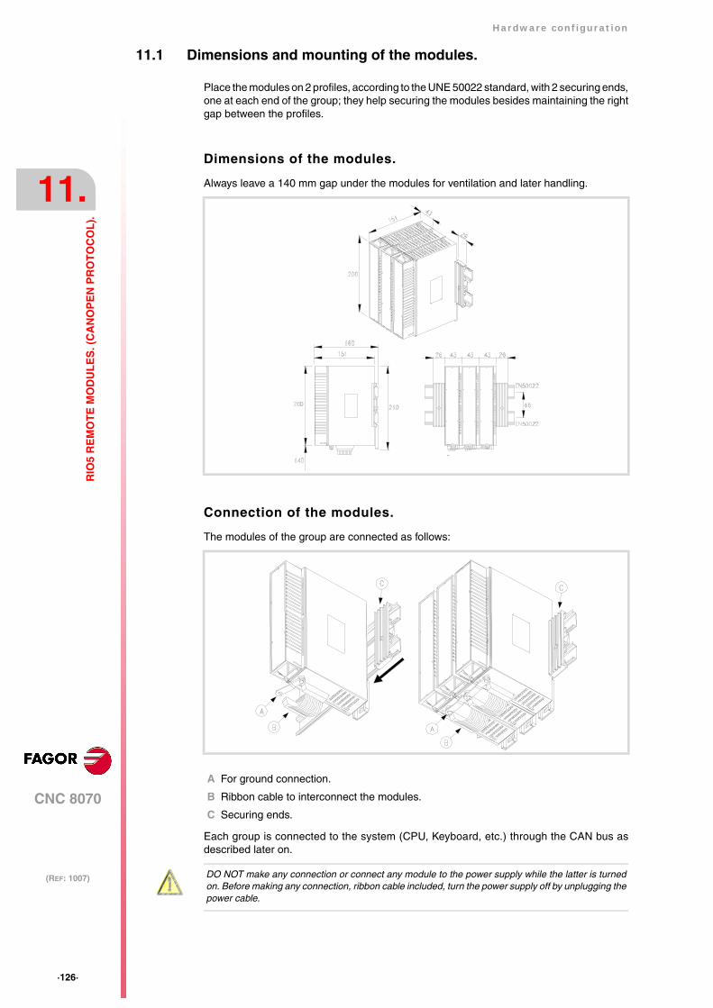
·126·
Hardware configuration
CNC 8070
11.
(REF: 1007)
RIO
5 R
EM
OT
E M
OD
UL
ES
. (C
AN
OP
EN
PR
OT
OC
OL
).
11.1 Dimensions and mounting of the modules.
Place the modules on 2 profiles, according to the UNE 50022 standard, with 2 securing ends,one at each end of the group; they help securing the modules besides maintaining the rightgap between the profiles.
Dimensions of the modules.
Always leave a 140 mm gap under the modules for ventilation and later handling.
Connection of the modules.
The modules of the group are connected as follows:
A For ground connection.
B Ribbon cable to interconnect the modules.
C Securing ends.
Each group is connected to the system (CPU, Keyboard, etc.) through the CAN bus asdescribed later on.
DO NOT make any connection or connect any module to the power supply while the latter is turnedon. Before making any connection, ribbon cable included, turn the power supply off by unplugging thepower cable.
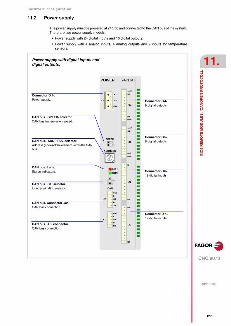
Hardware configuration
CNC 8070
11.
(REF: 1007)
·127·
RIO
5 R
EM
OT
E M
OD
UL
ES
. (C
AN
OP
EN
PR
OT
OC
OL
).
11.2 Power supply.
The power supply must be powered at 24 Vdc and connected to the CAN bus of the system.There are two power supply models.
• Power supply with 24 digital inputs and 16 digital outputs.
• Power supply with 4 analog inputs, 4 analog outputs and 2 inputs for temperaturesensors.
Connector ·X1·.Power supply.
Power supply with digital inputs anddigital outputs.
GNDLSH
SHH
X3
GNDLSH
SHH
X2
CAN
POWER 24I/16O
ERRRUN
X4
X5
X6
X7
I13
I24
I1
I12
GNDO16
O9+24V
GNDO8
O1+24V
X1
CHS
GND
+24V
4
01FEDCBA98 7 6 5 32
ADDRESS
SPEED10
LT
10
CAN bus. ·SPEED· selector.CAN bus transmission speed.
CAN bus. ·ADDRESS· selector.Address (node) of the element within the CANbus.
CAN bus. Leds.Status indicators.
CAN bus. ·ST· selector.Line terminating resistor.
CAN bus. Connector ·X2·.CAN bus connection.
CAN bus. ·X3· connector.CAN bus connection.
Connector ·X4·.8 digital outputs.
Connector ·X5·.8 digital outputs.
Connector ·X6·.12 digital inputs.
Connector ·X7·.12 digital inputs.
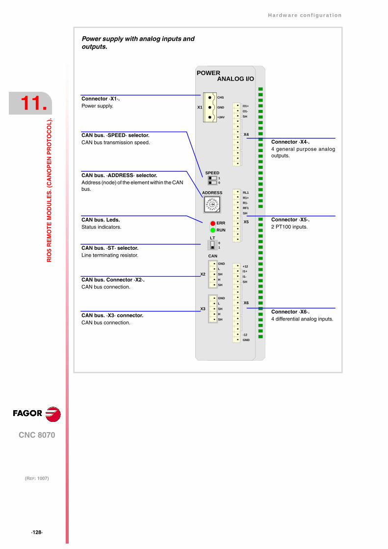
·128·
Hardware configuration
CNC 8070
11.
(REF: 1007)
RIO
5 R
EM
OT
E M
OD
UL
ES
. (C
AN
OP
EN
PR
OT
OC
OL
).
GNDLSH
SHH
X3
GNDLSH
SHH
X2
CAN
POWERANALOG I/O
ERRRUN
X1
CHS
GND
+24V
4
01FEDCBA98 7 6 5 32
ADDRESS
SPEED10
LT
10
X4
O1+O1-SH
X5
RL1R1+R1-RF1SH
X6
+12I1+I1-SH
-12GND
Connector ·X1·.Power supply.
Power supply with analog inputs andoutputs.
CAN bus. ·SPEED· selector.CAN bus transmission speed.
CAN bus. ·ADDRESS· selector.Address (node) of the element within the CANbus.
CAN bus. Leds.Status indicators.
CAN bus. ·ST· selector.Line terminating resistor.
CAN bus. Connector ·X2·.CAN bus connection.
CAN bus. ·X3· connector.CAN bus connection.
Connector ·X4·.4 general purpose analogoutputs.
Connector ·X5·.2 PT100 inputs.
Connector ·X6·.4 differential analog inputs.
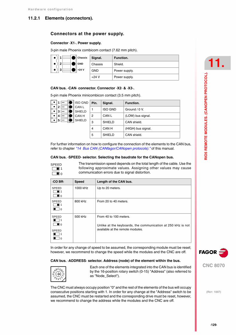
Hardware configuration
CNC 8070
11.
(REF: 1007)
·129·
RIO
5 R
EM
OT
E M
OD
UL
ES
. (C
AN
OP
EN
PR
OT
OC
OL
).
11.2.1 Elements (connectors).
Connectors at the power supply.
Connector ·X1·. Power supply.
3-pin male Phoenix combicom contact (7.62 mm pitch).
CAN bus. ·CAN· connector. Connector ·X2· & ·X3·.
5-pin male Phoenix minicombicon contact (3.5 mm pitch).
For further information on how to configure the connection of the elements to the CAN bus,refer to chapter "14 Bus CAN (CANfagor/CANopen protocols)." of this manual.
CAN bus. ·SPEED· selector. Selecting the baudrate for the CANopen bus.
In order for any change of speed to be assumed, the corresponding module must be reset;however, we recommend to change the speed while the modules and the CNC are off.
CAN bus. ·ADDRESS· selector. Address (node) of the element within the bus.
The CNC must always occupy position "0" and the rest of the elements of the bus will occupyconsecutive positions starting with 1. In order for any change at the "Address" switch to beassumed, the CNC must be restarted and the corresponding drive must be reset, however,we recommend to change the address while the modules and the CNC are off.
The transmission speed depends on the total length of the cable. Use thefollowing approximate values. Assigning other values may causecommunication errors due to signal distortion.
·CO BR· Speed Length of the CAN bus.
1000 kHz Up to 20 meters.
800 kHz From 20 to 40 meters.
500 kHz From 40 to 100 meters.
Unlike at the keyboards, the communication at 250 kHz is notavailable at the remote modules.
Each one of the elements integrated into the CAN bus is identifiedby the 16-position rotary switch (0-15) "Address" (also referred toas "Node_Select").
3
2
1
+24 V
GND
Chassis Signal. Function.
Chassis Shield.
GND Power supply.
+24 V Power supply.
Pin. Signal. Function.
1 ISO GND Ground / 0 V.
2 CAN L (LOW) bus signal.
3 SHIELD CAN shield.
4 CAN H (HIGH) bus signal.
5 SHIELD CAN shield.
SHIELDCAN HSHIELDCAN LISO GND
54321
SPEED10
SPEED10
10
SPEED
10
SPEED
10
SPEED
4
01FE
DCBA98 7 6 5 32
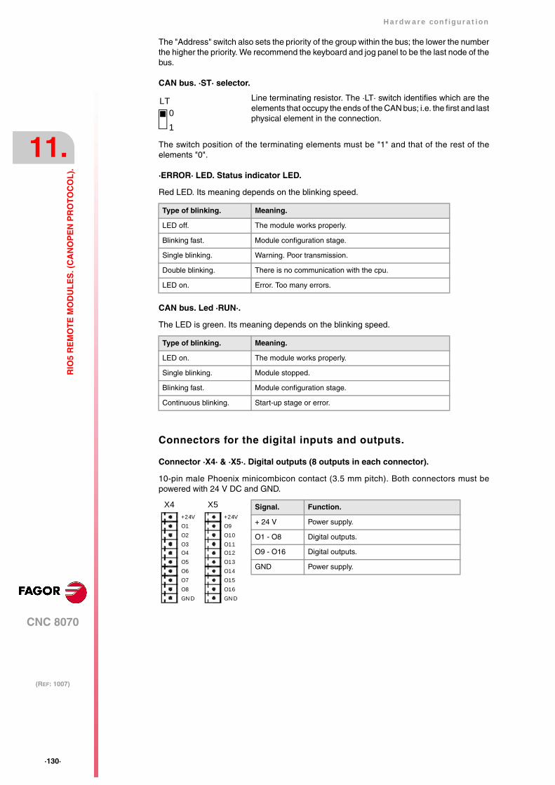
·130·
Hardware configuration
CNC 8070
11.
(REF: 1007)
RIO
5 R
EM
OT
E M
OD
UL
ES
. (C
AN
OP
EN
PR
OT
OC
OL
).
The "Address" switch also sets the priority of the group within the bus; the lower the numberthe higher the priority. We recommend the keyboard and jog panel to be the last node of thebus.
CAN bus. ·ST· selector.
The switch position of the terminating elements must be "1" and that of the rest of theelements "0".
·ERROR· LED. Status indicator LED.
Red LED. Its meaning depends on the blinking speed.
CAN bus. Led ·RUN·.
The LED is green. Its meaning depends on the blinking speed.
Connectors for the digital inputs and outputs.
Connector ·X4· & ·X5·. Digital outputs (8 outputs in each connector).
10-pin male Phoenix minicombicon contact (3.5 mm pitch). Both connectors must bepowered with 24 V DC and GND.
Line terminating resistor. The ·LT· switch identifies which are theelements that occupy the ends of the CAN bus; i.e. the first and lastphysical element in the connection.
Type of blinking. Meaning.
LED off. The module works properly.
Blinking fast. Module configuration stage.
Single blinking. Warning. Poor transmission.
Double blinking. There is no communication with the cpu.
LED on. Error. Too many errors.
Type of blinking. Meaning.
LED on. The module works properly.
Single blinking. Module stopped.
Blinking fast. Module configuration stage.
Continuous blinking. Start-up stage or error.
10
LT
Signal. Function.
+ 24 V Power supply.
O1 - O8 Digital outputs.
O9 - O16 Digital outputs.
GND Power supply.
O1+24V
X4
GN DO8
O2O3O4O5O6O7
O9+24V
X5
GN DO16
O10O11O12O13O14O15

Hardware configuration
CNC 8070
11.
(REF: 1007)
·131·
RIO
5 R
EM
OT
E M
OD
UL
ES
. (C
AN
OP
EN
PR
OT
OC
OL
).
Connector ·X6· & ·X7·. Digital inputs (12 inputs in each connector).
12-pin male Phoenix minicombicon contact (3.5 mm pitch).
Connectors for the analog inputs and outputs.
Connector ·X4·. General purpose analog outputs (4 outputs).
12-pin male Phoenix minicombicon contact (3.5 mm pitch).
Each analog output has three pins (O+, O-, SH). Use shielded cables connecting theirmeshes to the corresponding shield pin.
Connector ·X6·. Differential analog inputs (4 inputs).
15-pin male Phoenix minicombicon contact (3.5 mm pitch).
Each analog input has three pins (I+, I-, SH). Use shielded cables connecting their meshesto the corresponding shield pin.
Signal. Function.
I1 - I12 Digital inputs.
I13 - I24 Digital inputs.
I12
I1
I24
I13
X6 X7
I2I3I4I5I6I7I8I9I10I11 I23
I22I21I20I19I18I17I16I15I14
Signal. Function.
O1+ O1- Analog outputs.
O2+ O2- Analog outputs.
O3+ O3- Analog outputs.
O4+ O4- Analog outputs.
SH Shield connection.
SH
O1+
X4
O1-SHO2+O2-SHO3+O3-SHO4+O4-
+12I1+I1-SH
GN D
X6
I2+I2-SHI3+I3-
I4+I4-
-12
SH
SH
Signal. Function.
I1+ I1- Analog inputs.
I2+ I2- Analog inputs.
I3+ I3- Analog inputs.
I4+ I4- Analog inputs.
SH Shield connection.
+12 -12 12 V output.
GND 0 V reference signal.
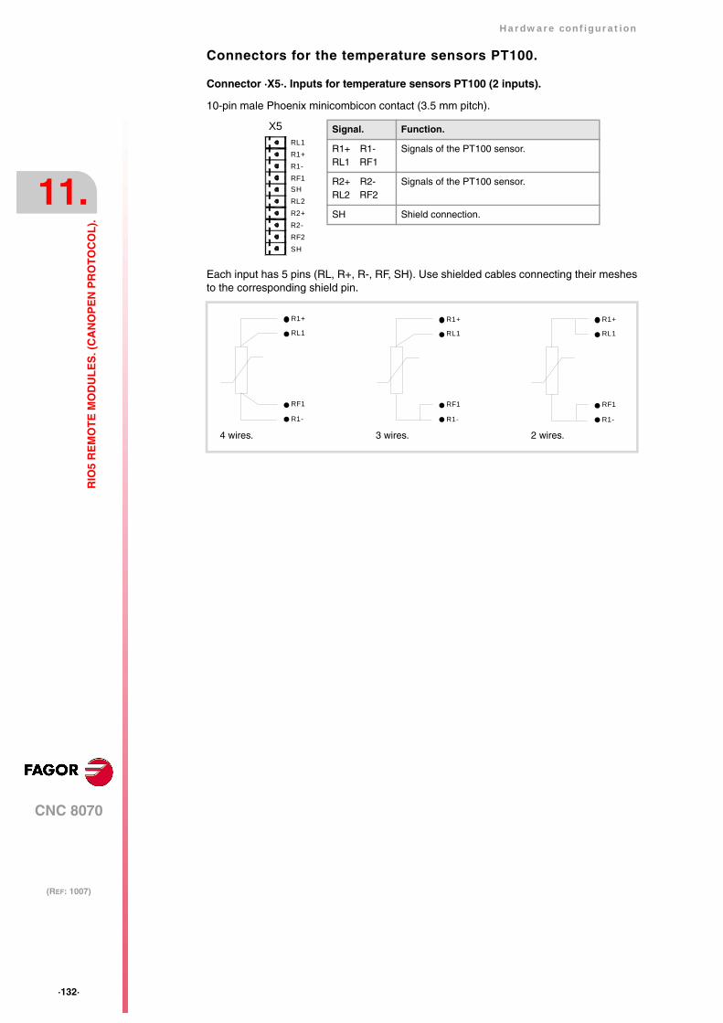
·132·
Hardware configuration
CNC 8070
11.
(REF: 1007)
RIO
5 R
EM
OT
E M
OD
UL
ES
. (C
AN
OP
EN
PR
OT
OC
OL
).
Connectors for the temperature sensors PT100.
Connector ·X5·. Inputs for temperature sensors PT100 (2 inputs).
10-pin male Phoenix minicombicon contact (3.5 mm pitch).
Each input has 5 pins (RL, R+, R-, RF, SH). Use shielded cables connecting their meshesto the corresponding shield pin.
Signal. Function.
R1+ R1-RL1 RF1
Signals of the PT100 sensor.
R2+ R2-RL2 RF2
Signals of the PT100 sensor.
SH Shield connection.
X5
R1+RL1
SHRF2
R1-RF1SHRL2R2+R2-
4 wires.
R1+
R1-
RL1
RF1
R1+
R1-
RL1
RF1
R1+
R1-
RL1
RF1
3 wires. 2 wires.
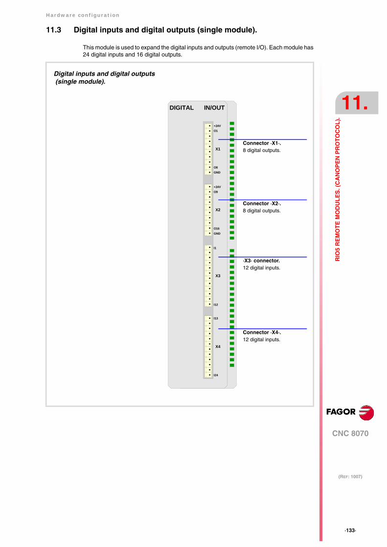
Hardware configuration
CNC 8070
11.
(REF: 1007)
·133·
RIO
5 R
EM
OT
E M
OD
UL
ES
. (C
AN
OP
EN
PR
OT
OC
OL
).
11.3 Digital inputs and digital outputs (single module).
This module is used to expand the digital inputs and outputs (remote I/O). Each module has24 digital inputs and 16 digital outputs.
DIGITAL IN/OUT
X1
X2
X3
X4
I13
I24
I1
I12
GNDO16
O9+24V
GNDO8
O1+24V
Digital inputs and digital outputs (single module).
Connector ·X1·.8 digital outputs.
Connector ·X2·.8 digital outputs.
·X3· connector.12 digital inputs.
Connector ·X4·.12 digital inputs.
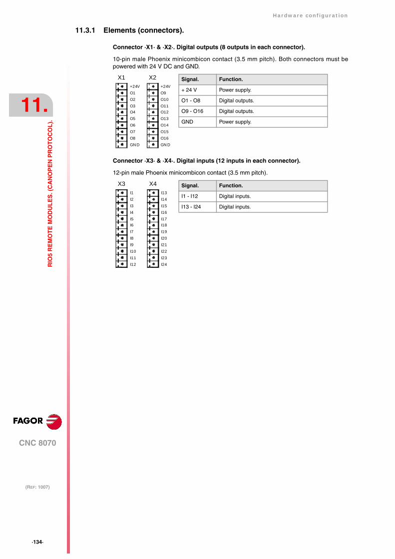
·134·
Hardware configuration
CNC 8070
11.
(REF: 1007)
RIO
5 R
EM
OT
E M
OD
UL
ES
. (C
AN
OP
EN
PR
OT
OC
OL
).
11.3.1 Elements (connectors).
Connector ·X1· & ·X2·. Digital outputs (8 outputs in each connector).
10-pin male Phoenix minicombicon contact (3.5 mm pitch). Both connectors must bepowered with 24 V DC and GND.
Connector ·X3· & ·X4·. Digital inputs (12 inputs in each connector).
12-pin male Phoenix minicombicon contact (3.5 mm pitch).
Signal. Function.
+ 24 V Power supply.
O1 - O8 Digital outputs.
O9 - O16 Digital outputs.
GND Power supply.
X1
O1+24V
GN DO8
O2O3O4O5O6O7
X2
O9+24V
GN DO16
O10O11O12O13O14O15
Signal. Function.
I1 - I12 Digital inputs.
I13 - I24 Digital inputs.
I12
I1
I24
I13
X3 X4
I2I3I4I5I6I7I8I9I10I11 I23
I22I21I20I19I18I17I16I15I14
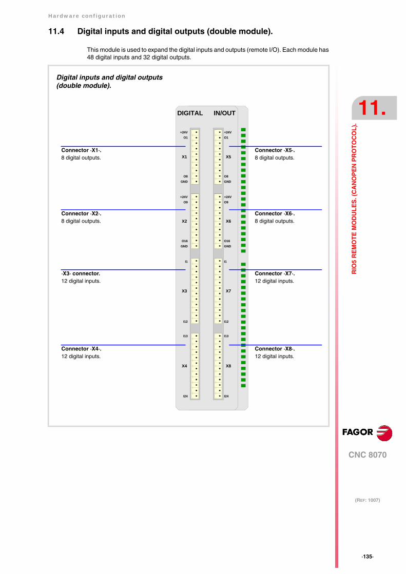
Hardware configuration
CNC 8070
11.
(REF: 1007)
·135·
RIO
5 R
EM
OT
E M
OD
UL
ES
. (C
AN
OP
EN
PR
OT
OC
OL
).
11.4 Digital inputs and digital outputs (double module).
This module is used to expand the digital inputs and outputs (remote I/O). Each module has48 digital inputs and 32 digital outputs.
DIGITAL IN/OUT
X5
X6
X7
X8
I13
I24
I1
I12
GNDO16
O9+24V
GNDO8
O1+24V
X1
X2
X3
X4
I13
I24
I1
I12
GNDO16
O9+24V
GNDO8
O1+24V
Digital inputs and digital outputs (double module).
Connector ·X5·.8 digital outputs.
Connector ·X6·.8 digital outputs.
Connector ·X7·.12 digital inputs.
Connector ·X8·.12 digital inputs.
Connector ·X1·.8 digital outputs.
Connector ·X2·.8 digital outputs.
·X3· connector.12 digital inputs.
Connector ·X4·.12 digital inputs.
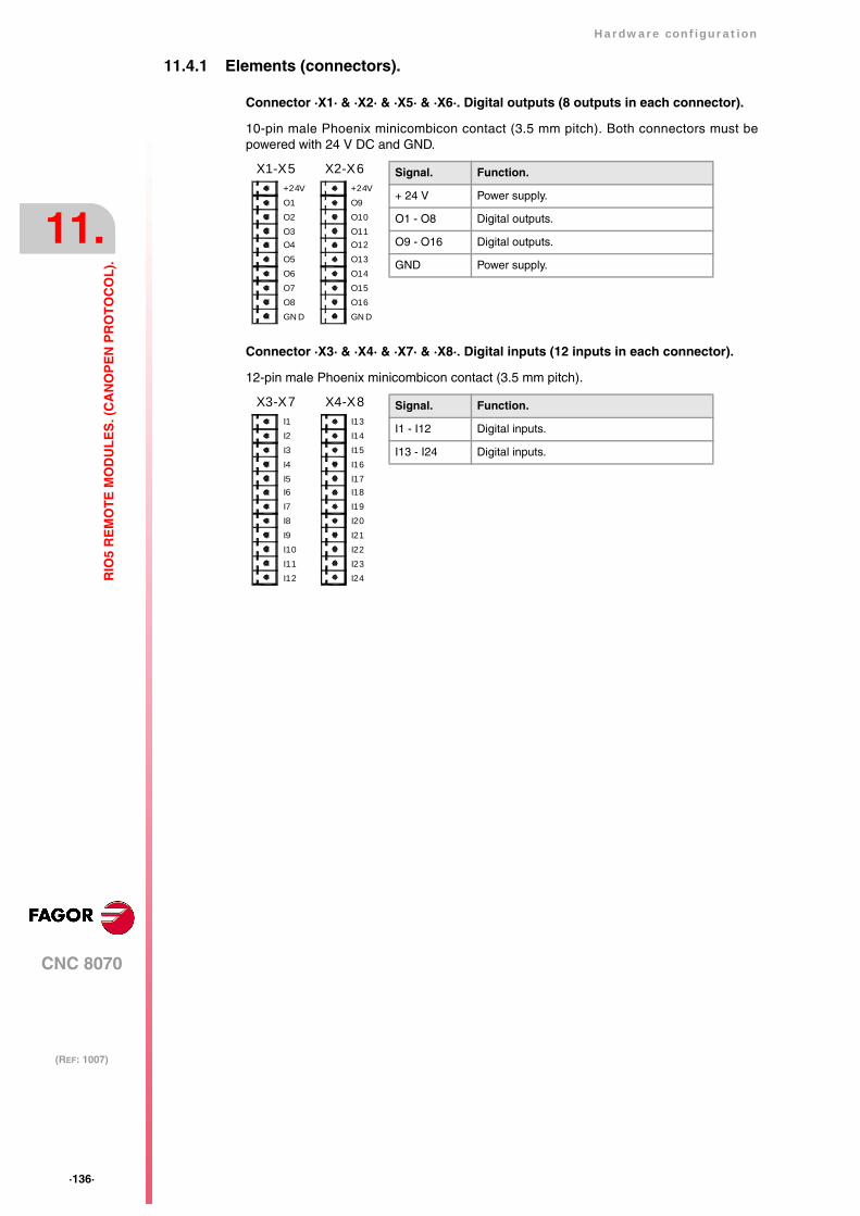
·136·
Hardware configuration
CNC 8070
11.
(REF: 1007)
RIO
5 R
EM
OT
E M
OD
UL
ES
. (C
AN
OP
EN
PR
OT
OC
OL
).
11.4.1 Elements (connectors).
Connector ·X1· & ·X2· & ·X5· & ·X6·. Digital outputs (8 outputs in each connector).
10-pin male Phoenix minicombicon contact (3.5 mm pitch). Both connectors must bepowered with 24 V DC and GND.
Connector ·X3· & ·X4· & ·X7· & ·X8·. Digital inputs (12 inputs in each connector).
12-pin male Phoenix minicombicon contact (3.5 mm pitch).
Signal. Function.
+ 24 V Power supply.
O1 - O8 Digital outputs.
O9 - O16 Digital outputs.
GND Power supply.
X1-X5
O1+24V
GN DO8
O2O3O4O5O6O7
X2-X6
O9+24V
GN DO16
O10O11O12O13O14O15
I12
I1
I24
I13
X3-X7 X4-X8
I2I3I4I5I6I7I8I9I10I11 I23
I22I21I20I19I18I17I16I15I14
Signal. Function.
I1 - I12 Digital inputs.
I13 - I24 Digital inputs.
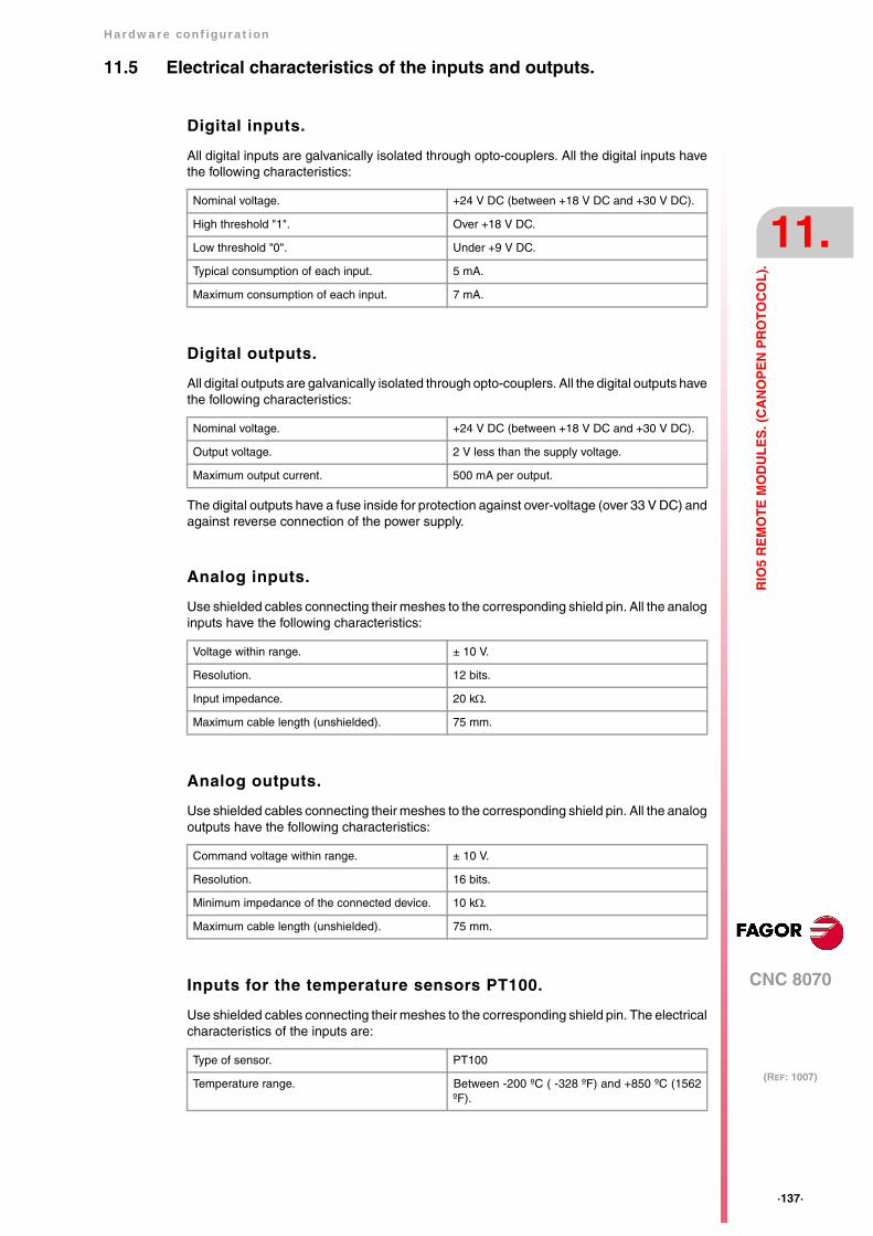
Hardware configuration
CNC 8070
11.
(REF: 1007)
·137·
RIO
5 R
EM
OT
E M
OD
UL
ES
. (C
AN
OP
EN
PR
OT
OC
OL
).
11.5 Electrical characteristics of the inputs and outputs.
Digital inputs.
All digital inputs are galvanically isolated through opto-couplers. All the digital inputs havethe following characteristics:
Digital outputs.
All digital outputs are galvanically isolated through opto-couplers. All the digital outputs havethe following characteristics:
The digital outputs have a fuse inside for protection against over-voltage (over 33 V DC) andagainst reverse connection of the power supply.
Analog inputs.
Use shielded cables connecting their meshes to the corresponding shield pin. All the analoginputs have the following characteristics:
Analog outputs.
Use shielded cables connecting their meshes to the corresponding shield pin. All the analogoutputs have the following characteristics:
Inputs for the temperature sensors PT100.
Use shielded cables connecting their meshes to the corresponding shield pin. The electricalcharacteristics of the inputs are:
Nominal voltage. +24 V DC (between +18 V DC and +30 V DC).
High threshold "1". Over +18 V DC.
Low threshold "0". Under +9 V DC.
Typical consumption of each input. 5 mA.
Maximum consumption of each input. 7 mA.
Nominal voltage. +24 V DC (between +18 V DC and +30 V DC).
Output voltage. 2 V less than the supply voltage.
Maximum output current. 500 mA per output.
Voltage within range. ± 10 V.
Resolution. 12 bits.
Input impedance. 20 kΩ.
Maximum cable length (unshielded). 75 mm.
Command voltage within range. ± 10 V.
Resolution. 16 bits.
Minimum impedance of the connected device. 10 kΩ.
Maximum cable length (unshielded). 75 mm.
Type of sensor. PT100
Temperature range. Between -200 ºC ( -328 ºF) and +850 ºC (1562ºF).

·138·
Hardware configuration
CNC 8070
11.
(REF: 1007)
RIO
5 R
EM
OT
E M
OD
UL
ES
. (C
AN
OP
EN
PR
OT
OC
OL
).
Resolution. 0.1 ºC
Typical consumption of each input. 2 mA.
Maximum cable length (unshielded). 75 mm.

Hardware configuration
CNC 8070
11.
(REF: 1007)
·139·
RIO
5 R
EM
OT
E M
OD
UL
ES
. (C
AN
OP
EN
PR
OT
OC
OL
).
11.6 Numbering of the digital inputs and outputs.
Use machine parameters to set the number of digital I/O modules connected to the sameCAN bus. If these parameters are not set, the CNC numbers the modules automaticallyaccording to the order of the remote groups (·ADDRESS· selector of the power supplymodule).
Numbering according to the order of the remote groups.
The CNC numbers the modules automatically according to the order of the remote groups(·ADDRESS· selector of the power supply module). Within each group, they are ordered fromleft to right.
Group ·1· Group ·2· Group ·3·
24 digital inputs. 24 + 48 digital inputs. 24 + 24 digital inputs.
16 digital outputs. 16 + 32 digital outputs. 16 + 16 digital outputs.
POWER 24I/16O
X1
CHS
GN D
24V
SPEED10
ADDRESS
ERR
RUN
CAN
01
LT
GN DLSHHSH
GN DLSHHSH
X2
X3X7
I24
I13
X6
I12
I1
X5
GN DO16
O9+24V
O1+24V
X4
GN DO8
POWER 24I/16O
X1
CHS
GN D
24V
SPEED10
ADDRESS
ERR
RUN
CAN
01
LT
GN DLSHHSH
GN DLSHHSH
X2
X3X7
I24
I13
X6
I12
I1
X5
GN DO16
O9+24V
O1+24V
X4
GN DO8
DIGITAL IN/OUT
X8
I24
I13
X7
I12
I1
X6
GNDO16
O9+24V
O1+24V
X5
GNDO8
X4
I24
I13
X3
I12
I1
X2
GN DO16
O9+24V
O1+24V
X1
GN DO8
DIGITAL IN/OUT
X4
I24
I13
X3
I12
I1
X2
GNDO16
O9+24V
O1+24V
X1
GNDO8
POWER 24I/16O
X1
CHS
GN D
24V
SPEED10
ADDRESS
ERR
RUN
CAN
01
LT
GN DLSHHSH
GN DLSHHSH
X2
X3X7
I24
I13
X6
I12
I1
X5
GN DO16
O9+24V
O1+24V
X4
GN DO8
Example 1.
Group ·1·(address = 1)
Group ·2·(address = 2)
Group ·3·(address = 3)
Digital inputs. 1 ·· 24 25 ·· 4849 ·· 96
97 ·· 120121 ·· 144
Digital outputs. 1 ·· 16 17 ·· 3233 ·· 64
65 ·· 8081 ·· 96
Example 2.
Group ·1·(address = 1)
Group ·2·(address = 3)
Group ·3·(address = 2)
Digital inputs. 1 ·· 24 73 ·· 9697 ·· 144
25 ·· 4849 ·· 72
Digital outputs. 1 ·· 16 49 ·· 6465 ·· 96
17 ·· 3233 ·· 48

·140·
Hardware configuration
CNC 8070
11.
(REF: 1007)
RIO
5 R
EM
OT
E M
OD
UL
ES
. (C
AN
OP
EN
PR
OT
OC
OL
).
Numbering by machine parameters.
When the numbering is set by machine parameters, each module is assigned a base indexand the inputs or outputs of that module are numbered after it. The double input/outputmodule must be assigned two base indexes for the inputs and two base indexes for theoutputs; one for each board;
The values of the base index must be comply with the formula "8n + 1" (i.e. 1, 9, 17, 25, etc.).The rest of the inputs or outputs are numbered sequentially. The base indexes may followany order, they do not have to be sequential.
When inserting a new module, the first modules will be assigned the numbering of the tableand the last one will be assigned the next valid base index after the highest one assigneduntil then.
Power supply.
Base index* Numbering.
Digital inputs. ·1· (I1 of X6) 1 ·· 24
Digital outputs. ·1· (I1 of X4) 1 ·· 16
Examples for numbering the different modules.
(*) For each base index, indicate the connector and the input or output it corresponds to.
POWER 24I/16O
X1
CHS
GN D
24V
SPEED10
ADDRESS
ERR
RUN
CAN
01
LT
GN DLSHHSH
GN DLSHHSH
X2
X3X7
I24
I13
X6
I12
I1
X5
GN DO16
O9+24V
O1+24V
X4
GN DO8
DIGITAL IN/OUT
X8
I24
I13
X7
I12
I1
X6
GN DO16
O9+24V
O1+24V
X5
GN DO8
X4
I24
I13
X3
I12
I1
X2
GN DO16
O9+24V
O1+24V
X1
GN DO8
POWER 24I/16O
X1
CHS
GN D
24V
SPEED10
ADDRESS
ERR
RUN
CAN
01
LT
GN DLSHHSH
GN DLSHHSH
X2
X3X7
I24
I13
X6
I12
I1
X5
GN DO16
O9+24V
O1+24V
X4
GN DO8
Power supply.
Base index* Numbering.
Digital inputs. ·1· (I1 of X6) 1 ·· 24
Digital outputs. ·1· (I1 of X4) 1 ·· 16
Module of digital inputs and outputs (double module).
Base index* Numbering.
Digital inputs. ·25· (I1 of X3)·49· (I1 of X7)
25 ·· 4849 ·· 64
Digital outputs. ·17· (I1 of X1)·33· (I1 of X5)
17 ·· 3233 ·· 48
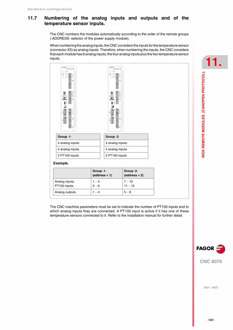
Hardware configuration
CNC 8070
11.
(REF: 1007)
·141·
RIO
5 R
EM
OT
E M
OD
UL
ES
. (C
AN
OP
EN
PR
OT
OC
OL
).
11.7 Numbering of the analog inputs and outputs and of thetemperature sensor inputs.
The CNC numbers the modules automatically according to the order of the remote groups(·ADDRESS· selector of the power supply module).
When numbering the analog inputs, the CNC considers the inputs for the temperature sensor(connector X5) as analog inputs. Therefore, when numbering the inputs, the CNC considersthat each module has 6 analog inputs; the four analog inputs plus the two temperature sensorinputs.
The CNC machine parameters must be set to indicate the number of PT100 inputs and towhich analog inputs they are connected. A PT100 input is active if it has one of thesetemperature sensors connected to it. Refer to the installation manual for further detail.
Group ·1·
4 analog inputs.
4 analog inputs.
2 PT100 inputs
Example.
Group ·1·(address = 1)
Group ·2·(address = 2)
Analog inputs.PT100 inputs.
1 ·· 45 ·· 6
7 ·· 1011 ·· 12
Analog outputs. 1 ·· 4 5 ·· 8
POWERANALOG I/O
X1
CHS
GN D
24V
SPEED10
ADDRESS
ERR
RUN
CAN
01
LT
GN DLSHHSH
GN DLSHHSH
X2
X3
0101
SH
X4
RL1R1R1RF1SH
X5
12I1I1SH
12GN D
X6
POWERANALOG I/O
X1
CHS
GN D
24V
SPEED10
ADDRESS
ERR
RUN
CAN
01
LT
GN DLSHHSH
GN DLSHHSH
X2
X3
0101
SH
X4
RL1R1R1RF1SH
X5
12I1I1SH
12GN D
X6
Group ·2·
4 analog inputs.
4 analog inputs.
2 PT100 inputs
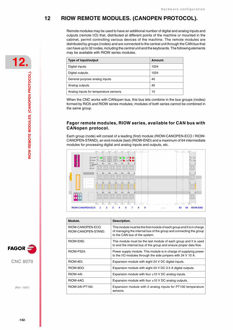
·142·
Hardware configuration
CNC 8070
12.
(REF: 1007)
RIO
W R
EM
OT
E M
OD
UL
ES
. (C
AN
OP
EN
PR
OT
OC
OL
).
12 RIOW REMOTE MODULES. (CANOPEN PROTOCOL).
Remote modules may be used to have an additional number of digital and analog inputs andoutputs (remote I/O) that, distributed at different points of the machine or mounted in thecabinet, permit controlling various devices of the machine. The remote modules aredistributed by groups (nodes) and are connected to the central unit through the CAN bus thatcan have up to 32 nodes, including the central unit and the keyboards. The following elementsmay be available with RIOW series modules.
When the CNC works with CANopen bus, this bus lets combine in the bus groups (nodes)formed by RIO5 and RIOW series modules; modules of both series cannot be combined inthe same group.
Fagor remote modules, RIOW series, available for CAN bus withCANopen protocol.
Each group (node) will consist of a leading (first) module (RIOW-CANOPEN-ECO / RIOW-CANOPEN-STAND), an end module (last) (RIOW-END) and a maximum of 64 intermediatemodules for processing digital and analog inputs and outputs, etc.
Type of input/output Amount.
Digital inputs. 1024
Digital outputs. 1024
General purpose analog inputs. 40
Analog outputs. 40
Analog inputs for temperature sensors. 10
Module. Description.
RIOW-CANOPEN-ECO.RIOW-CANOPEN-STAND.
This module must be the first module of each group and it is in chargeof managing the internal bus of the group and connecting the groupto the CAN bus of the system.
RIOW-END. This module must be the last module of each group and it is usedto end the internal bus of the group and ensure proper data flow.
RIOW-PS24. Power supply module. This module is in charge of supplying powerto the I/O modules through the side jumpers with 24 V 10 A.
RIOW-8DI. Expansion module with eight 24 V DC digital inputs.
RIOW-8DO. Expansion module with eight 24 V DC 0.5 A digital outputs.
RIOW-4AI. Expansion module with four ±10 V DC analog inputs.
RIOW-4AO. Expansion module with four ±10 V DC analog outputs.
RIOW-2AI-PT100. Expansion module with 2 analog inputs for PT100 temperaturesensors.
STOP
RUN
TX
RX
I/O
Overflow
56
78
12
34
ON
24V 24V 0V 0V 4 8
1 5
2 6
3 7
CA
DB
4 8
1 5
2 6
3 7
ABCD
EFGH
4 8
1 5
2 6
3 7
ABCD
EFGH
4 8
1 5
2 6
3 7
CA
DB
4 8
1 5
2 6
3 7
CA
DB
4 8
1 5
2 6
3 7
CA
DB
RIOW-CANOPEN-ECO 2 3 4 5 71 64 RIOW-END
4 8
1 5
2 6
3 7
CA
DB
638 9 . . .

Hardware configuration
CNC 8070
12.
(REF: 1007)
·143·
RIO
W R
EM
OT
E M
OD
UL
ES
. (C
AN
OP
EN
PR
OT
OC
OL
).
12.1 Dimensions of the modules.
A2
E1
STOP
RUN
TX
RX
I/O
Overflow
56
78
12
34
ON
24V 24V 0V 0V
A1
E2
C
4 8
1 5
2 6
3 7
CA
DB
A3
D
4 8
1 5
2 6
3 7
CA
DB
56
78
12
34
ON
STOP
RUN
TX
RXOverflow
I/O
E2
C
D
C
D
E1
·144·
Hardware configuration
CNC 8070
12.
(REF: 1007)
RIO
W R
EM
OT
E M
OD
UL
ES
. (C
AN
OP
EN
PR
OT
OC
OL
).
12.2 Technical and electrical characteristics.
12.2.1 Technical characteristics.
Mechanical characteristics.
Vibrations (module RIOW-CANOPEN-ECO).
• Meets the IEC60068-2-6 standard.
• Sweep sine trial with a frequency step of 1 octave/minute (±10%) and 10 sweeps longper axis, on each of the three vertical axes.
Vibrations (module RIOW-CANOPEN-STAND).
• Meets the IEC60068-2-6 standard.
• Sweep sine trial with a frequency step of 1 octave/minute (±10%) and on each of the threeaxes.
Choques.
• Meets the IEC60068-2-27 standard.
• Semi-sinusoidal pulses with 15g peaks for 11 ms. 3 pulses in each direction (positive andnegative) of each of the three vertical axes (18 pulses in all).
Free fall.
• Meets the IEC60068-2-32 standard.
• Up to 1 m with the unit in its original packaging.
Electromagnetic compatibility.
Regulations valid for all RIOW modules.
Immunity against disturbances (regulation EN 50082-2:1996).
• Meets the EN 61000-4-2 regulation.
• Meets the EN 61000-4-3 regulation.
• Meets the EN 61000-4-4 regulation.
• Meets the EN 61000-4-6 regulation.
Regulations valid for all RIOW modules except for RIOW-CANOPEN-ECO and RIOW-CANOPEN-STAND modules.
Emission of disturbances (regulation EN 50081-1:1993).
• Meets the EN 55022 regulation.
Regulations only valid for all RIOW-CANOPEN-ECO and RIOW-CANOPEN-STANDmodules.
Emission of disturbances (regulation EN 50081-2:1994).
• Meets the EN 55011 regulation.
10 Hz ≤ f < 57 Hz Constant movement with an amplitude of 0.075 mm.
57 Hz ≤ f < 150 Hz Constant 1g acceleration.
5 Hz ≤ f < 9 Hz 1.750 mm amplitude (constant) or 3.5 mm (short periods).
9 Hz ≤ f < 150 Hz 0.5 mm (constant acceleration) or 1g (short periods).

Hardware configuration
CNC 8070
12.
(REF: 1007)
·145·
RIO
W R
EM
OT
E M
OD
UL
ES
. (C
AN
OP
EN
PR
OT
OC
OL
).
Ambient conditions.
• Relative humidity: 5-95% without condensation.
• Work temperature: 0-55 ºC.
• Storage temperature: Between -20 ºC ( 77 ºF) and +85 ºC (158 ºF).
• Resistance to harmful substances: Meets standards IEC 60068-2-42 and IEC 60068-2-43.
Degree of protection.
• It meets the protection standard IP 20.
The machine manufacturer must comply with the EN 60204-1 (IEC-204-1) regulationregarding electrical shocks in case of defective input/output pins with external power supplywhen not plugging the connector before turning the power supply on.
Do not get into the inside of the unit. This unit MUST NOT be opened by unauthorized personnel. Onlypersonnel authorized by Fagor Automation may manipulate the inside of this unit.

·146·
Hardware configuration
CNC 8070
12.
(REF: 1007)
RIO
W R
EM
OT
E M
OD
UL
ES
. (C
AN
OP
EN
PR
OT
OC
OL
).
12.2.2 Electrical characteristics of the inputs and outputs.
Digital outputs.
All digital outputs have a status indicating LED that turns on when the output is active. Theoutputs are protected with opto-couplers and protected against short-circuits.
Digital inputs.
All digital inputs have a status indicating LED that turns on when the input is active. The inputsare protected by opto-couplers.
Analog inputs.
All analog inputs have a status indicating LED that turns on when there is an over-voltageor an under-voltage.
Use shielded cables connecting their meshes to the corresponding shield pin. Maximumcable length (unshielded): 75 mm.
Analog outputs.
Each input has 2 LED's; a green one that turns on when the bus transmission is OK and ared one that turns on when there is an overload or a short-circuit to ground at any of theoutputs.
Use shielded cables connecting their meshes to the corresponding shield pin. Maximumcable length (unshielded): 75 mm.
Technical characteristics.
Number of outputs. 8 outputs per module.
Nominal voltage. +24 V DC (between -15 % and +20 %).
Typical consumption. 15 mA per module plus the consumption of theelements.
Output current. 500 mA per output.
Technical characteristics.
Number of inputs. 8 inputs per module.
Nominal voltage. +24 V DC (between -15 % and +20 %).
Low threshold "0". Within -3 and 5 V DC.
High threshold "1". Within 15 and 30 V DC.
Typical consumption. 2.8 mA.
Technical characteristics.
Number of inputs. 4 inputs per module.
Voltage range. ± 10 V.
Maximum input voltage. ± 40 V.
Typical input impedance. > 100 kΩ
Measuring error (25 ºC). <± 0.1 %
Resolution. 12 bits.
Typical consumption of each input. 0.5 mA.
Technical characteristics.
Number of outputs. 4 outputs per module.
Voltage range. ± 10 V.
Impedance of the connected device. > 5 kΩ
Output filter time (typical value). 100 ms.
Measuring error (25 ºC). <± 0.1 %
Resolution. 12 bits.
Typical consumption of each input. 0.5 mA.
Hardware configuration
CNC 8070
12.
(REF: 1007)
·147·
RIO
W R
EM
OT
E M
OD
UL
ES
. (C
AN
OP
EN
PR
OT
OC
OL
).
Analog inputs for PT100 temperature sensors.
Each input has 2 LED's; a green one that turns on when the bus transmission is OK and ared one that turns on when there is a reading error at the inputs.
The inputs are protected by opto-couplers. Use shielded cables connecting their meshes tothe corresponding shield pin. Maximum cable length (unshielded): 75 mm.
Technical characteristics.
Number of inputs. 2 inputs per module.
Type of sensor. PT100
Type of connection. 2-wire or 3-wire interface.
Temperature range. Between -200 ºC ( -328 ºF) and +850 ºC (1562 ºF).
Resolution. 0.1 ºC
Measuring error (25 ºC). <± 0.2 %
Response time, from when the sensor isconnected until the first correct measure isobtained.
4 s.
Typical consumption of each input. 0.5 mA.
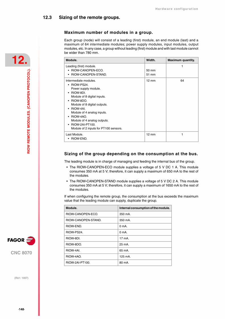
·148·
Hardware configuration
CNC 8070
12.
(REF: 1007)
RIO
W R
EM
OT
E M
OD
UL
ES
. (C
AN
OP
EN
PR
OT
OC
OL
).
12.3 Sizing of the remote groups.
Maximum number of modules in a group.
Each group (node) will consist of a leading (first) module, an end module (last) and amaximum of 64 intermediate modules; power supply modules, input modules, outputmodules, etc. In any case, a group without leading (first) module and with last module cannotbe wider than 780 mm.
Sizing of the group depending on the consumption at the bus.
The leading module is in charge of managing and feeding the internal bus of the group.
• The RIOW-CANOPEN-ECO module supplies a voltage of 5 V DC 1 A. This moduleconsumes 350 mA at 5 V; therefore, it can supply a maximum of 650 mA to the rest ofthe modules.
• The RIOW-CANOPEN-STAND module supplies a voltage of 5 V DC 2 A. This moduleconsumes 350 mA at 5 V; therefore, it can supply a maximum of 1650 mA to the rest ofthe modules.
If when configuring the remote group, the consumption at the bus exceeds the maximumvalue that the leading module can supply, duplicate the group.
Module. Width. Maximum quantity.
Leading (first) module.• RIOW-CANOPEN-ECO.• RIOW-CANOPEN-STAND.
50 mm51 mm
1
Intermediate modules.• RIOW-PS24.
Power supply module.• RIOW-8DI.
Module of 8 digital inputs.• RIOW-8DO.
Module of 8 digital outputs.• RIOW-4AI.
Module of 4 analog inputs.• RIOW-4AO.
Module of 4 analog outputs.• RIOW-2AI-PT100.
Module of 2 inputs for PT100 sensors.
12 mm 64
Last Module.• RIOW-END.
12 mm 1
Module. Internal consumption of the module.
RIOW-CANOPEN-ECO. 350 mA.
RIOW-CANOPEN-STAND. 350 mA.
RIOW-END. 0 mA.
RIOW-PS24. 0 mA.
RIOW-8DI. 17 mA.
RIOW-8DO. 25 mA.
RIOW-4AI. 65 mA.
RIOW-4AO. 125 mA.
RIOW-2AI-PT100. 80 mA.
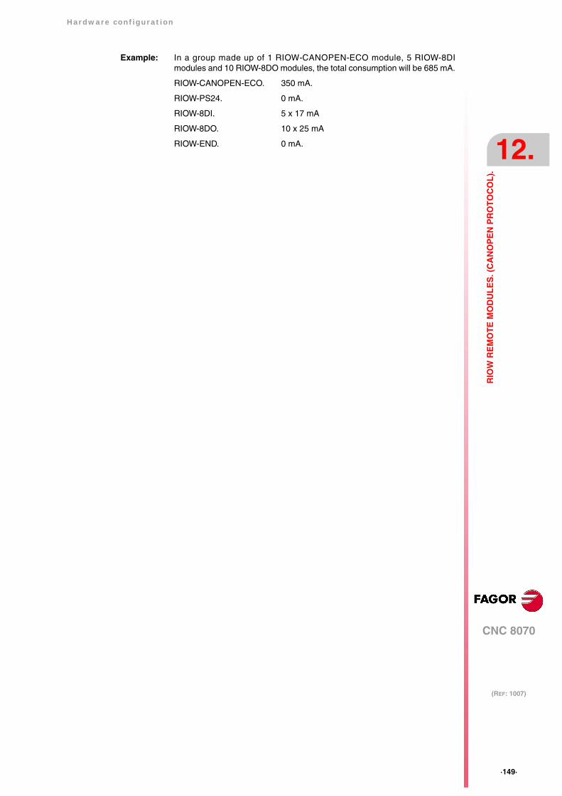
Hardware configuration
CNC 8070
12.
(REF: 1007)
·149·
RIO
W R
EM
OT
E M
OD
UL
ES
. (C
AN
OP
EN
PR
OT
OC
OL
).
Example: In a group made up of 1 RIOW-CANOPEN-ECO module, 5 RIOW-8DImodules and 10 RIOW-8DO modules, the total consumption will be 685 mA.
RIOW-CANOPEN-ECO. 350 mA.
RIOW-PS24. 0 mA.
RIOW-8DI. 5 x 17 mA
RIOW-8DO. 10 x 25 mA
RIOW-END. 0 mA.
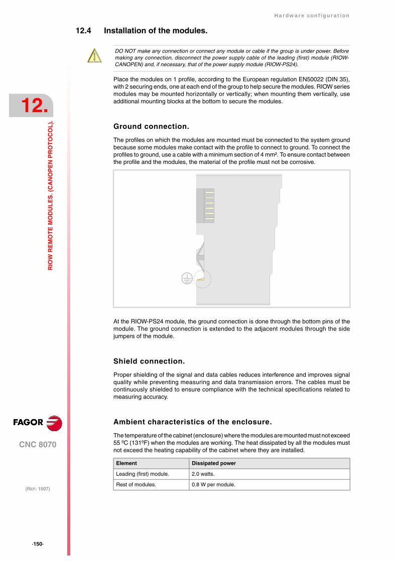
·150·
Hardware configuration
CNC 8070
12.
(REF: 1007)
RIO
W R
EM
OT
E M
OD
UL
ES
. (C
AN
OP
EN
PR
OT
OC
OL
).
12.4 Installation of the modules.
Place the modules on 1 profile, according to the European regulation EN50022 (DIN 35),with 2 securing ends, one at each end of the group to help secure the modules. RIOW seriesmodules may be mounted horizontally or vertically; when mounting them vertically, useadditional mounting blocks at the bottom to secure the modules.
Ground connection.
The profiles on which the modules are mounted must be connected to the system groundbecause some modules make contact with the profile to connect to ground. To connect theprofiles to ground, use a cable with a minimum section of 4 mm². To ensure contact betweenthe profile and the modules, the material of the profile must not be corrosive.
At the RIOW-PS24 module, the ground connection is done through the bottom pins of themodule. The ground connection is extended to the adjacent modules through the sidejumpers of the module.
Shield connection.
Proper shielding of the signal and data cables reduces interference and improves signalquality while preventing measuring and data transmission errors. The cables must becontinuously shielded to ensure compliance with the technical specifications related tomeasuring accuracy.
Ambient characteristics of the enclosure.
The temperature of the cabinet (enclosure) where the modules are mounted must not exceed55 ºC (131ºF) when the modules are working. The heat dissipated by all the modules mustnot exceed the heating capability of the cabinet where they are installed.
DO NOT make any connection or connect any module or cable if the group is under power. Beforemaking any connection, disconnect the power supply cable of the leading (first) module (RIOW-CANOPEN) and, if necessary, that of the power supply module (RIOW-PS24).
Element Dissipated power
Leading (first) module. 2.0 watts.
Rest of modules. 0.8 W per module.
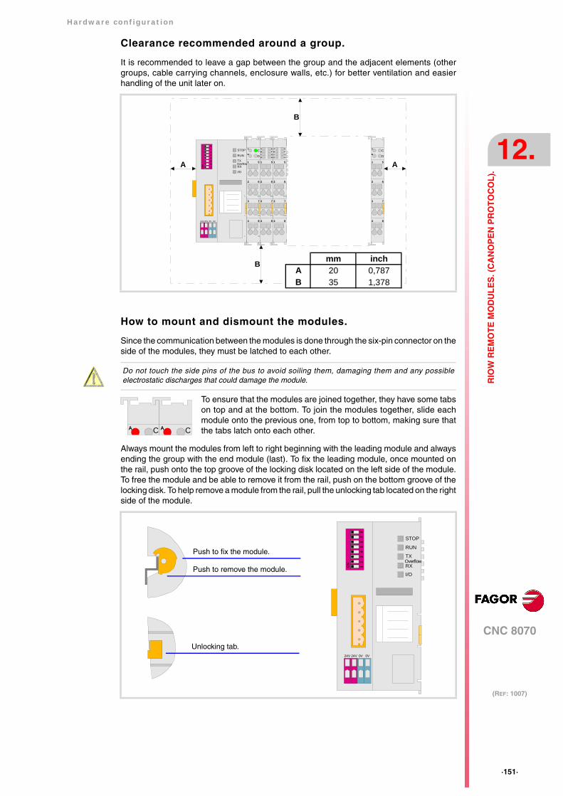
Hardware configuration
CNC 8070
12.
(REF: 1007)
·151·
RIO
W R
EM
OT
E M
OD
UL
ES
. (C
AN
OP
EN
PR
OT
OC
OL
).
Clearance recommended around a group.
It is recommended to leave a gap between the group and the adjacent elements (othergroups, cable carrying channels, enclosure walls, etc.) for better ventilation and easierhandling of the unit later on.
How to mount and dismount the modules.
Since the communication between the modules is done through the six-pin connector on theside of the modules, they must be latched to each other.
Always mount the modules from left to right beginning with the leading module and alwaysending the group with the end module (last). To fix the leading module, once mounted onthe rail, push onto the top groove of the locking disk located on the left side of the module.To free the module and be able to remove it from the rail, push on the bottom groove of thelocking disk. To help remove a module from the rail, pull the unlocking tab located on the rightside of the module.
STOP
RUN
TX
RX
I/O
Overflow
56
78
12
34
ON
24V 24V 0V 0V 4 8
1 5
2 6
3 7
CA
DB
4 8
1 5
2 6
3 7
CA
DB
4 8
1 5
2 6
3 7
ABCD
EFGH
4 8
1 5
2 6
3 7
ABCD
EFGH
A A
B
B mm inchA 20 0,787B 35 1,378
Do not touch the side pins of the bus to avoid soiling them, damaging them and any possibleelectrostatic discharges that could damage the module.
To ensure that the modules are joined together, they have some tabson top and at the bottom. To join the modules together, slide eachmodule onto the previous one, from top to bottom, making sure thatthe tabs latch onto each other. CA CA
STOP
RUN
TX
RX
I/O
Overflow
56
78
12
34
ON
24V 24V 0V 0V
Push to fix the module.
Push to remove the module.
Unlocking tab.
·152·
Hardware configuration
CNC 8070
12.
(REF: 1007)
RIO
W R
EM
OT
E M
OD
UL
ES
. (C
AN
OP
EN
PR
OT
OC
OL
).
Side voltage jumpers.
Some modules, e.g. the digital inputs module, have some jumpers on the left side forreceiving and sending a current of 10 A needed to supply the module.
The jumpers of a module must latch into the grooves of the previous module. It must be bornein mind that not all the modules have the same number of jumpers and grooves. Beforemounting a module with jumpers, make sure that the previous module has enough groovesto receive the jumpers.
Cable connection.
Each connector only admits one cable. To insert several cables into one connector, join thecables at a terminal and insert the terminal into the connector.
The cables are secured into the connectors by pressure. Insert a tool into the square holelocated on top of the connector, this opens the connector. Insert the cable into the connectorand remove the tool. After removing the tool, the cable stays fixed.
The voltage jumpers are sharp. Handle the modules carefully to prevent getting hurt.
DO NOT make any connection or connect any module or cable if the group is under power. Beforemaking any connection, disconnect the power supply cable of the leading (first) module (RIOW-CANOPEN) and, if necessary, that of the power supply module (RIOW-PS24).
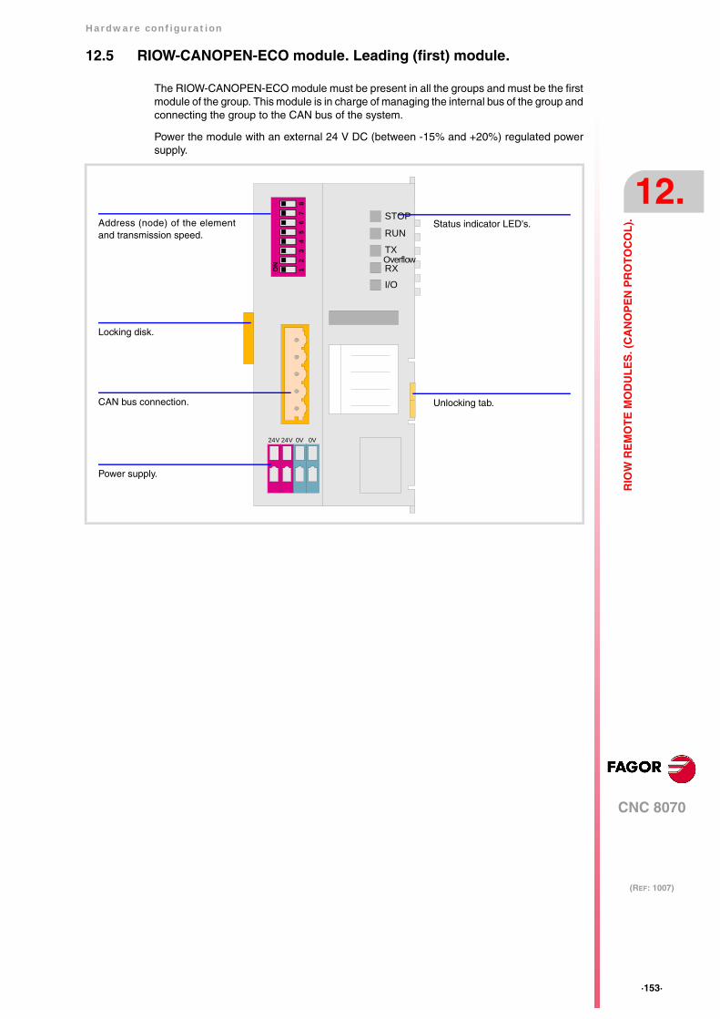
Hardware configuration
CNC 8070
12.
(REF: 1007)
·153·
RIO
W R
EM
OT
E M
OD
UL
ES
. (C
AN
OP
EN
PR
OT
OC
OL
).
12.5 RIOW-CANOPEN-ECO module. Leading (first) module.
The RIOW-CANOPEN-ECO module must be present in all the groups and must be the firstmodule of the group. This module is in charge of managing the internal bus of the group andconnecting the group to the CAN bus of the system.
Power the module with an external 24 V DC (between -15% and +20%) regulated powersupply.
STOP
RUN
TX
RX
I/O
Overflow
56
78
12
34
ON
24V 24V 0V 0V
Power supply.
CAN bus connection.
Address (node) of the elementand transmission speed.
Locking disk.
Status indicator LED's.
Unlocking tab.

·154·
Hardware configuration
CNC 8070
12.
(REF: 1007)
RIO
W R
EM
OT
E M
OD
UL
ES
. (C
AN
OP
EN
PR
OT
OC
OL
).
12.5.1 Elements (connectors).
Power supply.
CAN bus connection.
Address (node) of the element and transmission speed.
Status indicator LED's.
The module has the following LED's on top. These LED's indicate the status of the node andof the communication through the CAN bus. See "12.5.3 Meaning of the LED's." on page157.
The dipswitch may be used to select the address of the node and thetransmission speed. See "12.5.2 Node configuration." on page 155.
When using the CANopen protocol, the transmission speed at the bus isdefined in each node. All the nodes must work at the same speed.
Signal Function
24 V Power supply.
0 V Power supply.
24V 24V 0V 0V
CAN L
SHIELD
CAN H
N.C.
GND
Pin Signal Function
5 N.C. Not being used.
4 CAN H (HIGH) bus signal.
3 SHIELD CAN shield.
2 CAN L (LOW) bus signal.
1 GND Ground / 0 V.
56
78
12
34
ON
ON
The dip-switch of the RIOW-CANOPEN-ECO and RIOW-CANOPEN-STAND modules is the same butrotated 180º, so the ·ON· position is inverted between them.i
LED. Color. Meaning.
STOP Red. The node is stopped.
RUN Green. The node works properly.
TX overflow Red. Data sending error.
RX overflow Red. Data reception error.
I/O Red.Green.Orange.
Status of the communication with the I/O modules.

Hardware configuration
CNC 8070
12.
(REF: 1007)
·155·
RIO
W R
EM
OT
E M
OD
UL
ES
. (C
AN
OP
EN
PR
OT
OC
OL
).
12.5.2 Node configuration.
The node is configured using the dipswitches to select the node address and thetransmission speed.
Configuring the node speed.
To select the speed of the node, the module must be in configuration mode (all thedipswitches in the ·off· position). After turning the module on in configuration mode, the top4 LED's of the module blink indicating the speed selected at the module. The STOP LEDcorresponds to dipswitch ·1·, the RUN to dipswitch ·2·, the TX to dipswitch ·3· and the RXto dipswitch ·4·. The first time the module is configured, the TX LED blinks indicating thatno valid speed has been selected.
The first 4 dipswitches are used to select the speed; the rest must be in the ·off· position.To select the speed, put the corresponding dipswitches in the ·on· position. The transmissionspeed depends on the total length of the cable. Use the following approximate values.Assigning other values may cause communication errors due to signal distortion.
To save the selected speed, put dipswitch ·8· in the ·on· position. After saving theconfiguration, the corresponding LED's turn on to indicate the module speed. For 1 MHz,all four LED's turn on.
Once the speed has been selected, turn the module off by removing power and set dip-switch·8· in the ·off· position. Bear in mind that the next time the module is turned on, the positionof the dipswitches will indicate the address (node number) of the group.
Configuring the address (node number) of the group.
Each one of the elements integrated into the CAN bus is identified by its address or nodenumber. The CNC must always occupy position "0" and the rest of the elements of the buswill occupy consecutive positions starting with 1.
The address (node number) of the group is selected while the module is off. Select the speedby putting the corresponding dipswitches in the ·on· position. The binary meaning of eachdipswitch increases according to its number; dipswitch ·1· for address 1, dipswitch ·3· foraddress 4 and so on.
If when turning the module on, all the dipswitches are not in the ·off· position, the position of thedipswitches will be the new address (node number) of the group. i
Dipswitch Speed Length of the CAN bus.
1000 kHz Up to 20 meters.
800 kHz From 20 to 40 meters.
500 kHz From 40 to 100 meters.
250 kHz From 100 to 500 meters.
Address ·1·. Address ·3·. Address ·9·.
4321
ON
4321
ON
4321
ON
4321
ON
4321
ON
4321
ON
4321
ON
·156·
Hardware configuration
CNC 8070
12.
(REF: 1007)
RIO
W R
EM
OT
E M
OD
UL
ES
. (C
AN
OP
EN
PR
OT
OC
OL
).
Line terminating resistor.
In the CAN bus, it is necessary to use a line terminating resistor to identify which are theelements that occupy the ends of the bus; i.e. the first and last physical element in theconnection. For the central unit, the terminating resistor is factory installed because the CNCis always at one end of the bus.
The RIOW series modules do not have a factory-installed line terminating resistor. The RIOWmodule mounted at the end of the bus must have a 120 Ω line terminating resistor betweenpins CAN_H and CAN_L to avoid signal deflections (rebounds).
Hardware configuration
CNC 8070
12.
(REF: 1007)
·157·
RIO
W R
EM
OT
E M
OD
UL
ES
. (C
AN
OP
EN
PR
OT
OC
OL
).
12.5.3 Meaning of the LED's.
While staring the module up, the LED's indicate the stage the node is in and its status.
When a module is in configuration mode (dipswitch value equal to ·0·), the LED's indicatethe speed selected at the module. See "12.5.2 Node configuration." on page 155.
LED's STOP, RUN, TX overflow and RX overflow.
The top four LED's of the module (STOP, RUN, TX overflow and RX overflow) indicate thestatus of the node and of the communication through the CAN bus.
Led I/O.
Three-colored LED (orange/red/green) that indicates the bus status and the errors found.
Node status. Meaning.
Initializing stage After starting up or after a reset, the module goes into the initializingstage to run an autotest. During the initializing stage, the I/O LEDblinks orange until it changes to red.
• If the module is properly initialized, it changes to the pre-operative stage, the I/O LED changes to green and the RUNLED blinks.
• If the module detects any problem in the initializing stage, itchanges to the stop stage, the I/O LED blinks red and the STOPLED turns on. The blinking rate of the I/O LED indicates thedetected error.
Pre-operative stage. In this stage, the module configures the bus.During the pre-operative stage, the I/O LED turns green and theRUN LED blinks.
Operative stage. In this stage, the module is ready to work.In the operative stage, the I/O and RUN LED's turn green.
Stop stage. This stage indicates an error at the node.The STOP LED turns on in the stop stage.
STOP RUN Meaning.
OFF OFF Module turned off or in initializing stage.
OFF Blinking slow Module in pre-operative stage.
OFF ON Module in operative stage.
ON OFF Module in stop stage. Node configuration error or bus error.
OFF Blinking fast Module in pre-operative stage. Module error.
Blinking fast Blinking fast Module in pre-operative stage. Module error.
Blinking fast OFF Module in pre-operative stage. Module error.
TX overflow RX overflow Meaning.
OFF OFF Module turned off or in initializing stage.
- - - ON Data reception error.
ON - - - Data sending error.
Blinking fast Blinking fast Too many errors at the node.
Led I/O. Meaning.
Off. There's no data at the data bus.
Green. The module is transmitting data.
Red. Hardware error.
Blinking orange. The module is in the initializing stage.
Blinking red. Data bus error.
Cyclic red blinking. Error code.
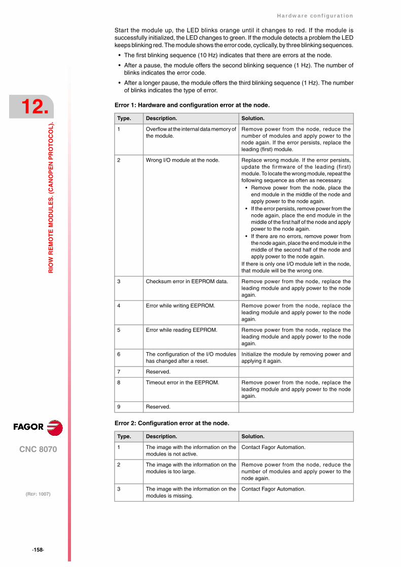
·158·
Hardware configuration
CNC 8070
12.
(REF: 1007)
RIO
W R
EM
OT
E M
OD
UL
ES
. (C
AN
OP
EN
PR
OT
OC
OL
).
Start the module up, the LED blinks orange until it changes to red. If the module issuccessfully initialized, the LED changes to green. If the module detects a problem the LEDkeeps blinking red. The module shows the error code, cyclically, by three blinking sequences.
• The first blinking sequence (10 Hz) indicates that there are errors at the node.
• After a pause, the module offers the second blinking sequence (1 Hz). The number ofblinks indicates the error code.
• After a longer pause, the module offers the third blinking sequence (1 Hz). The numberof blinks indicates the type of error.
Error 1: Hardware and configuration error at the node.
Error 2: Configuration error at the node.
Type. Description. Solution.
1 Overflow at the internal data memory ofthe module.
Remove power from the node, reduce thenumber of modules and apply power to thenode again. If the error persists, replace theleading (first) module.
2 Wrong I/O module at the node. Replace wrong module. If the error persists,update the firmware of the leading (first)module. To locate the wrong module, repeat thefollowing sequence as often as necessary.
• Remove power from the node, place theend module in the middle of the node andapply power to the node again.
• If the error persists, remove power from thenode again, place the end module in themiddle of the first half of the node and applypower to the node again.
• If there are no errors, remove power fromthe node again, place the end module in themiddle of the second half of the node andapply power to the node again.
If there is only one I/O module left in the node,that module will be the wrong one.
3 Checksum error in EEPROM data. Remove power from the node, replace theleading module and apply power to the nodeagain.
4 Error while writing EEPROM. Remove power from the node, replace theleading module and apply power to the nodeagain.
5 Error while reading EEPROM. Remove power from the node, replace theleading module and apply power to the nodeagain.
6 The configuration of the I/O moduleshas changed after a reset.
Initialize the module by removing power andapplying it again.
7 Reserved.
8 Timeout error in the EEPROM. Remove power from the node, replace theleading module and apply power to the nodeagain.
9 Reserved.
Type. Description. Solution.
1 The image with the information on themodules is not active.
Contact Fagor Automation.
2 The image with the information on themodules is too large.
Remove power from the node, reduce thenumber of modules and apply power to thenode again.
3 The image with the information on themodules is missing.
Contact Fagor Automation.
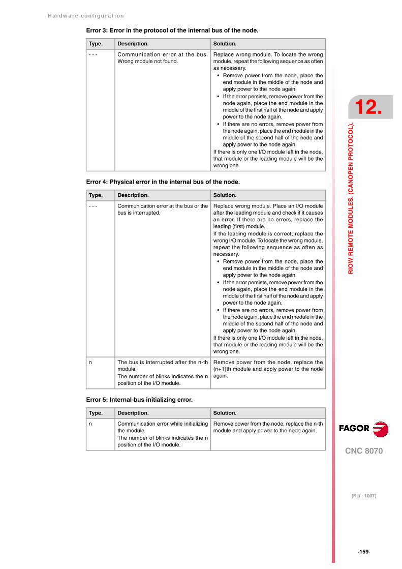
Hardware configuration
CNC 8070
12.
(REF: 1007)
·159·
RIO
W R
EM
OT
E M
OD
UL
ES
. (C
AN
OP
EN
PR
OT
OC
OL
).
Error 3: Error in the protocol of the internal bus of the node.
Error 4: Physical error in the internal bus of the node.
Error 5: Internal-bus initializing error.
Type. Description. Solution.
- - - Communication error at the bus.Wrong module not found.
Replace wrong module. To locate the wrongmodule, repeat the following sequence as oftenas necessary.
• Remove power from the node, place theend module in the middle of the node andapply power to the node again.
• If the error persists, remove power from thenode again, place the end module in themiddle of the first half of the node and applypower to the node again.
• If there are no errors, remove power fromthe node again, place the end module in themiddle of the second half of the node andapply power to the node again.
If there is only one I/O module left in the node,that module or the leading module will be thewrong one.
Type. Description. Solution.
- - - Communication error at the bus or thebus is interrupted.
Replace wrong module. Place an I/O moduleafter the leading module and check if it causesan error. If there are no errors, replace theleading (first) module. If the leading module is correct, replace thewrong I/O module. To locate the wrong module,repeat the following sequence as often asnecessary.
• Remove power from the node, place theend module in the middle of the node andapply power to the node again.
• If the error persists, remove power from thenode again, place the end module in themiddle of the first half of the node and applypower to the node again.
• If there are no errors, remove power fromthe node again, place the end module in themiddle of the second half of the node andapply power to the node again.
If there is only one I/O module left in the node,that module or the leading module will be thewrong one.
n The bus is interrupted after the n-thmodule.The number of blinks indicates the nposition of the I/O module.
Remove power from the node, replace the(n+1)th module and apply power to the nodeagain.
Type. Description. Solution.
n Communication error while initializingthe module. The number of blinks indicates the nposition of the I/O module.
Remove power from the node, replace the n-thmodule and apply power to the node again.
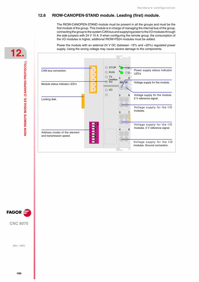
·160·
Hardware configuration
CNC 8070
12.
(REF: 1007)
RIO
W R
EM
OT
E M
OD
UL
ES
. (C
AN
OP
EN
PR
OT
OC
OL
).
12.6 RIOW-CANOPEN-STAND module. Leading (first) module.
The RIOW-CANOPEN-STAND module must be present in all the groups and must be thefirst module of the group. This module is in charge of managing the internal bus of the group,connecting the group to the system CAN bus and supplying power to the I/O modules throughthe side jumpers with 24 V 10 A. If when configuring the remote group, the consumption ofthe I/O modules is higher, additional RIOW-PS24 modules must be added.
Power the module with an external 24 V DC (between -15% and +20%) regulated powersupply. Using the wrong voltage may cause severe damage to the components.
4 8
1 5
2 6
3 7
CA
DB
56
78
12
34
ON
STOP
RUN
TX
RXOverflow
I/O
24V 0V
CAN bus connection.
Address (node) of the elementand transmission speed.
Locking disk.
Power supply status indicatorLED's
Vol tage supply for the I /Omodules.
Vol tage supply for the I /Omodules. 0 V reference signal.
Vo l tage supp ly fo r the I /Omodules. Ground connection.
Module status indicator LED's
Voltage supply for the module.0 V reference signal.
Voltage supply for the module.
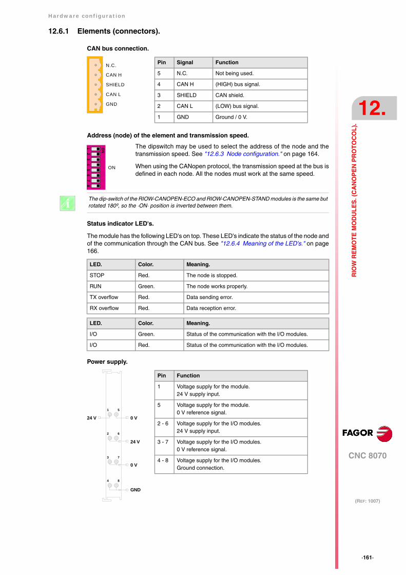
Hardware configuration
CNC 8070
12.
(REF: 1007)
·161·
RIO
W R
EM
OT
E M
OD
UL
ES
. (C
AN
OP
EN
PR
OT
OC
OL
).
12.6.1 Elements (connectors).
CAN bus connection.
Address (node) of the element and transmission speed.
Status indicator LED's.
The module has the following LED's on top. These LED's indicate the status of the node andof the communication through the CAN bus. See "12.6.4 Meaning of the LED's." on page166.
Power supply.
The dipswitch may be used to select the address of the node and thetransmission speed. See "12.6.3 Node configuration." on page 164.
When using the CANopen protocol, the transmission speed at the bus isdefined in each node. All the nodes must work at the same speed.
CAN L
SHIELD
CAN H
N.C.
GND
Pin Signal Function
5 N.C. Not being used.
4 CAN H (HIGH) bus signal.
3 SHIELD CAN shield.
2 CAN L (LOW) bus signal.
1 GND Ground / 0 V.
56
78
12
34
ON
ON
The dip-switch of the RIOW-CANOPEN-ECO and RIOW-CANOPEN-STAND modules is the same butrotated 180º, so the ·ON· position is inverted between them.i
LED. Color. Meaning.
STOP Red. The node is stopped.
RUN Green. The node works properly.
TX overflow Red. Data sending error.
RX overflow Red. Data reception error.
LED. Color. Meaning.
I/O Green. Status of the communication with the I/O modules.
I/O Red. Status of the communication with the I/O modules.
4 8
1 5
2 6
3 7
24 V
0 V
GND
0 V24 V
Pin Function
1 Voltage supply for the module.24 V supply input.
5 Voltage supply for the module.0 V reference signal.
2 - 6 Voltage supply for the I/O modules.24 V supply input.
3 - 7 Voltage supply for the I/O modules.0 V reference signal.
4 - 8 Voltage supply for the I/O modules.Ground connection.
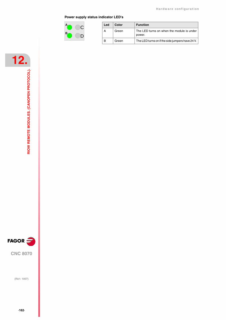
·162·
Hardware configuration
CNC 8070
12.
(REF: 1007)
RIO
W R
EM
OT
E M
OD
UL
ES
. (C
AN
OP
EN
PR
OT
OC
OL
).
Power supply status indicator LED's
Led Color Function
A Green The LED turns on when the module is underpower.
B Green The LED turns on if the side jumpers have 24 V.
CA
DB
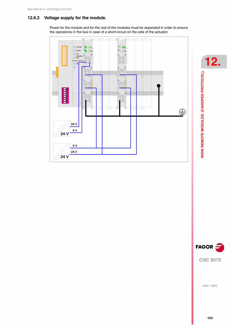
Hardware configuration
CNC 8070
12.
(REF: 1007)
·163·
RIO
W R
EM
OT
E M
OD
UL
ES
. (C
AN
OP
EN
PR
OT
OC
OL
).
12.6.2 Voltage supply for the module.
Power for the module and for the rest of the modules must be separated in order to ensurethe operations in the bus in case of a short-circuit on the side of the actuator.
4 8
1 5
2 6
3 7
CA
DB
56
78
12
34
ON
STOP
RUN
TX
RXOverflow
I/O
4 8
1 5
2 6
3 7
CA
DB
24 V
24 V
24 V
0 V
24 V
0 V
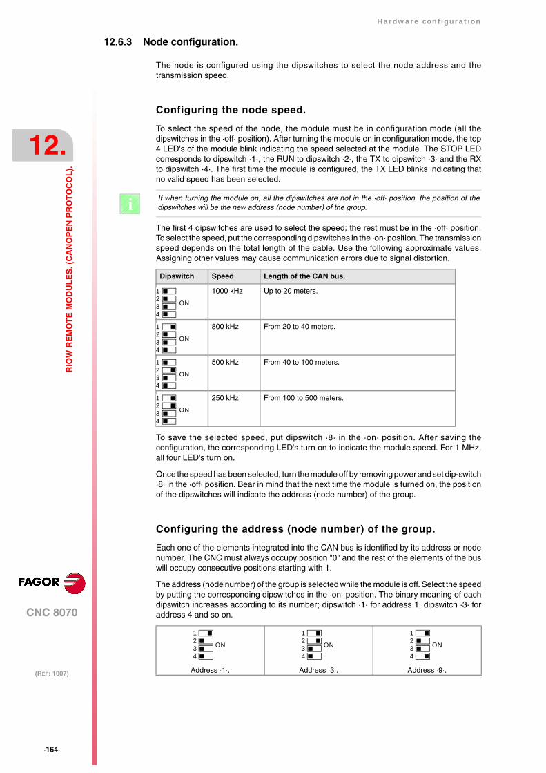
·164·
Hardware configuration
CNC 8070
12.
(REF: 1007)
RIO
W R
EM
OT
E M
OD
UL
ES
. (C
AN
OP
EN
PR
OT
OC
OL
).
12.6.3 Node configuration.
The node is configured using the dipswitches to select the node address and thetransmission speed.
Configuring the node speed.
To select the speed of the node, the module must be in configuration mode (all thedipswitches in the ·off· position). After turning the module on in configuration mode, the top4 LED's of the module blink indicating the speed selected at the module. The STOP LEDcorresponds to dipswitch ·1·, the RUN to dipswitch ·2·, the TX to dipswitch ·3· and the RXto dipswitch ·4·. The first time the module is configured, the TX LED blinks indicating thatno valid speed has been selected.
The first 4 dipswitches are used to select the speed; the rest must be in the ·off· position.To select the speed, put the corresponding dipswitches in the ·on· position. The transmissionspeed depends on the total length of the cable. Use the following approximate values.Assigning other values may cause communication errors due to signal distortion.
To save the selected speed, put dipswitch ·8· in the ·on· position. After saving theconfiguration, the corresponding LED's turn on to indicate the module speed. For 1 MHz,all four LED's turn on.
Once the speed has been selected, turn the module off by removing power and set dip-switch·8· in the ·off· position. Bear in mind that the next time the module is turned on, the positionof the dipswitches will indicate the address (node number) of the group.
Configuring the address (node number) of the group.
Each one of the elements integrated into the CAN bus is identified by its address or nodenumber. The CNC must always occupy position "0" and the rest of the elements of the buswill occupy consecutive positions starting with 1.
The address (node number) of the group is selected while the module is off. Select the speedby putting the corresponding dipswitches in the ·on· position. The binary meaning of eachdipswitch increases according to its number; dipswitch ·1· for address 1, dipswitch ·3· foraddress 4 and so on.
If when turning the module on, all the dipswitches are not in the ·off· position, the position of thedipswitches will be the new address (node number) of the group. i
Dipswitch Speed Length of the CAN bus.
1000 kHz Up to 20 meters.
800 kHz From 20 to 40 meters.
500 kHz From 40 to 100 meters.
250 kHz From 100 to 500 meters.
Address ·1·. Address ·3·. Address ·9·.
1234
ON
1234
ON
1234
ON
1234
ON
1234
ON
1234
ON
1234
ON

Hardware configuration
CNC 8070
12.
(REF: 1007)
·165·
RIO
W R
EM
OT
E M
OD
UL
ES
. (C
AN
OP
EN
PR
OT
OC
OL
).
Line terminating resistor.
In the CAN bus, it is necessary to use a line terminating resistor to identify which are theelements that occupy the ends of the bus; i.e. the first and last physical element in theconnection. For the central unit, the terminating resistor is factory installed because the CNCis always at one end of the bus.
The RIOW series modules do not have a factory-installed line terminating resistor. The RIOWmodule mounted at the end of the bus must have a 120 Ω line terminating resistor betweenpins CAN_H and CAN_L to avoid signal deflections (rebounds).
·166·
Hardware configuration
CNC 8070
12.
(REF: 1007)
RIO
W R
EM
OT
E M
OD
UL
ES
. (C
AN
OP
EN
PR
OT
OC
OL
).
12.6.4 Meaning of the LED's.
While staring the module up, the LED's indicate the stage the node is in and its status.
When a module is in configuration mode (dipswitch value equal to ·0·), the LED's indicatethe speed selected at the module. See "12.6.3 Node configuration." on page 164.
LED's STOP, RUN, TX overflow and RX overflow.
The top four LED's of the module (STOP, RUN, TX overflow and RX overflow) indicate thestatus of the node and of the communication through the CAN bus.
Led I/O.
Three-colored LED (orange/red/green) that indicates the bus status and the errors found.
Node status. Meaning.
Initializing stage After starting up or after a reset, the module goes into the initializing stageto run an autotest. During the initializing stage, the I/O LED blinks orangeuntil it changes to red.
• If the module is properly initialized, it changes to the pre-operativestage, the I/O LED changes to green and the RUN LED blinks.
• If the module detects any problem in the initializing stage, it changesto the stop stage, the I/O LED blinks red and the STOP LED turnson. The blinking rate of the I/O LED indicates the detected error.
Pre-operative stage. In this stage, the module configures the bus.During the pre-operative stage, the I/O LED turns green and the RUNLED blinks.
Operative stage. In this stage, the module is ready to work.In the operative stage, the I/O and RUN LED's turn green.
Stop stage. This stage indicates an error at the node.The STOP LED turns on in the stop stage.
STOP RUN Meaning.
OFF OFF Module turned off or in initializing stage.
OFF Blinking slow Module in pre-operative stage.
OFF ON Module in operative stage.
ON OFF Module in stop stage. Node configuration error or bus error.
OFF Blinking fast Module in pre-operative stage. Module error.
Blinking fast Blinking fast Module in pre-operative stage. Module error.
Blinking fast OFF Module in pre-operative stage. Module error.
TX overflow RX overflow Meaning.
OFF OFF Module turned off or in initializing stage.
- - - ON Data reception error.
ON - - - Data sending error.
Blinking fast Blinking fast Too many errors at the node.
Led I/O. Meaning.
off There's no data at the data bus
Green. The module is transmitting data.
Red. Hardware error.
Blinking orange. The module is in the initializing stage.
Blinking red. Data bus error.
Cyclic red blinking. Error code.
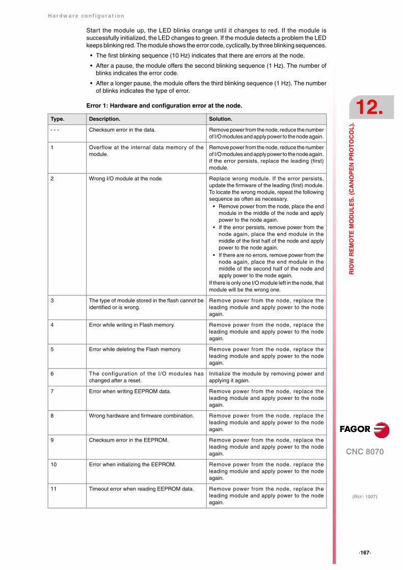
Hardware configuration
CNC 8070
12.
(REF: 1007)
·167·
RIO
W R
EM
OT
E M
OD
UL
ES
. (C
AN
OP
EN
PR
OT
OC
OL
).
Start the module up, the LED blinks orange until it changes to red. If the module issuccessfully initialized, the LED changes to green. If the module detects a problem the LEDkeeps blinking red. The module shows the error code, cyclically, by three blinking sequences.
• The first blinking sequence (10 Hz) indicates that there are errors at the node.
• After a pause, the module offers the second blinking sequence (1 Hz). The number ofblinks indicates the error code.
• After a longer pause, the module offers the third blinking sequence (1 Hz). The numberof blinks indicates the type of error.
Error 1: Hardware and configuration error at the node.
Type. Description. Solution.
- - - Checksum error in the data. Remove power from the node, reduce the numberof I/O modules and apply power to the node again.
1 Overflow at the internal data memory of themodule.
Remove power from the node, reduce the numberof I/O modules and apply power to the node again.If the error persists, replace the leading (first)module.
2 Wrong I/O module at the node. Replace wrong module. If the error persists,update the firmware of the leading (first) module.To locate the wrong module, repeat the followingsequence as often as necessary.
• Remove power from the node, place the endmodule in the middle of the node and applypower to the node again.
• If the error persists, remove power from thenode again, place the end module in themiddle of the first half of the node and applypower to the node again.
• If there are no errors, remove power from thenode again, place the end module in themiddle of the second half of the node andapply power to the node again.
If there is only one I/O module left in the node, thatmodule will be the wrong one.
3 The type of module stored in the flash cannot beidentified or is wrong.
Remove power from the node, replace theleading module and apply power to the nodeagain.
4 Error while writing in Flash memory. Remove power from the node, replace theleading module and apply power to the nodeagain.
5 Error while deleting the Flash memory. Remove power from the node, replace theleading module and apply power to the nodeagain.
6 The configuration of the I/O modules haschanged after a reset.
Initialize the module by removing power andapplying it again.
7 Error when writing EEPROM data. Remove power from the node, replace theleading module and apply power to the nodeagain.
8 Wrong hardware and firmware combination. Remove power from the node, replace theleading module and apply power to the nodeagain.
9 Checksum error in the EEPROM. Remove power from the node, replace theleading module and apply power to the nodeagain.
10 Error when initializing the EEPROM. Remove power from the node, replace theleading module and apply power to the nodeagain.
11 Timeout error when reading EEPROM data. Remove power from the node, replace theleading module and apply power to the nodeagain.
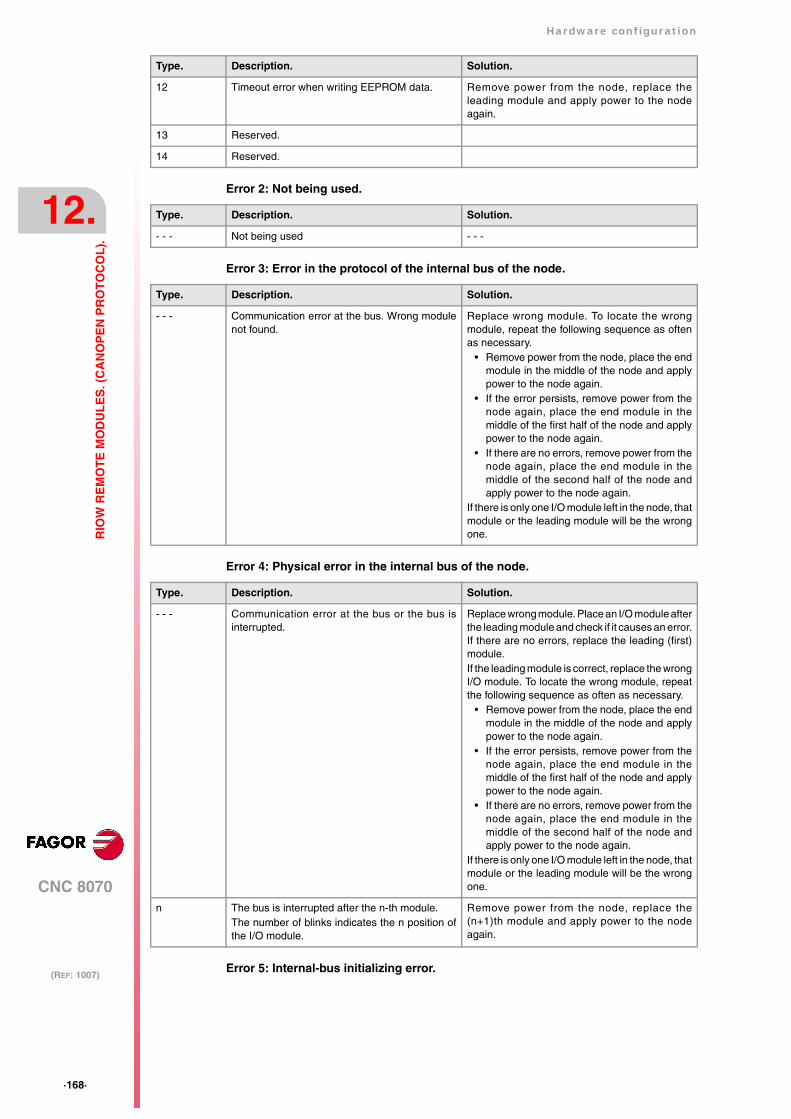
·168·
Hardware configuration
CNC 8070
12.
(REF: 1007)
RIO
W R
EM
OT
E M
OD
UL
ES
. (C
AN
OP
EN
PR
OT
OC
OL
).
Error 2: Not being used.
Error 3: Error in the protocol of the internal bus of the node.
Error 4: Physical error in the internal bus of the node.
Error 5: Internal-bus initializing error.
12 Timeout error when writing EEPROM data. Remove power from the node, replace theleading module and apply power to the nodeagain.
13 Reserved.
14 Reserved.
Type. Description. Solution.
Type. Description. Solution.
- - - Not being used - - -
Type. Description. Solution.
- - - Communication error at the bus. Wrong modulenot found.
Replace wrong module. To locate the wrongmodule, repeat the following sequence as oftenas necessary.
• Remove power from the node, place the endmodule in the middle of the node and applypower to the node again.
• If the error persists, remove power from thenode again, place the end module in themiddle of the first half of the node and applypower to the node again.
• If there are no errors, remove power from thenode again, place the end module in themiddle of the second half of the node andapply power to the node again.
If there is only one I/O module left in the node, thatmodule or the leading module will be the wrongone.
Type. Description. Solution.
- - - Communication error at the bus or the bus isinterrupted.
Replace wrong module. Place an I/O module afterthe leading module and check if it causes an error.If there are no errors, replace the leading (first)module. If the leading module is correct, replace the wrongI/O module. To locate the wrong module, repeatthe following sequence as often as necessary.
• Remove power from the node, place the endmodule in the middle of the node and applypower to the node again.
• If the error persists, remove power from thenode again, place the end module in themiddle of the first half of the node and applypower to the node again.
• If there are no errors, remove power from thenode again, place the end module in themiddle of the second half of the node andapply power to the node again.
If there is only one I/O module left in the node, thatmodule or the leading module will be the wrongone.
n The bus is interrupted after the n-th module.The number of blinks indicates the n position ofthe I/O module.
Remove power from the node, replace the(n+1)th module and apply power to the nodeagain.

Hardware configuration
CNC 8070
12.
(REF: 1007)
·169·
RIO
W R
EM
OT
E M
OD
UL
ES
. (C
AN
OP
EN
PR
OT
OC
OL
).
Type. Description. Solution.
n Communication error while initializing themodule. The number of blinks indicates the n position ofthe I/O module.
Remove power from the node, replace the n-thmodule and apply power to the node again.

·170·
Hardware configuration
CNC 8070
12.
(REF: 1007)
RIO
W R
EM
OT
E M
OD
UL
ES
. (C
AN
OP
EN
PR
OT
OC
OL
).
12.7 RIOW-PS24 module.
This module is in charge of supplying power to the I/O modules through the side jumperswith 24 V 10 A. If when configuring the remote group, the consumption of the I/O modulesis higher, additional RIOW-PS24 modules must be added.
Power the module with an external 24 V DC regulated power supply.
4 8
1 5
2 6
3 7
CA
DB
Power supply.
0 V reference signal.
Ground connection.
Power supply.
0 V reference signal.
Ground connection.
LED indicating the voltage at sidejumpers.
Jumpers to power the next module.
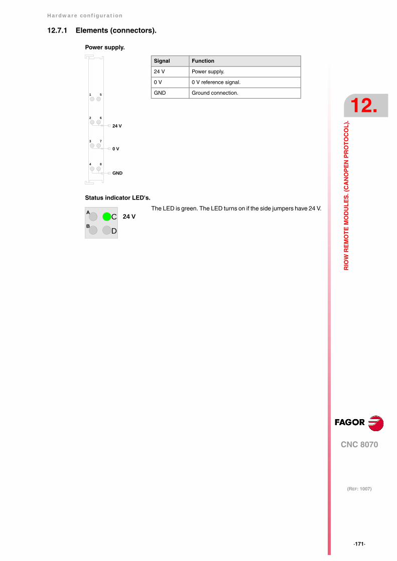
Hardware configuration
CNC 8070
12.
(REF: 1007)
·171·
RIO
W R
EM
OT
E M
OD
UL
ES
. (C
AN
OP
EN
PR
OT
OC
OL
).
12.7.1 Elements (connectors).
Power supply.
Status indicator LED's.
The LED is green. The LED turns on if the side jumpers have 24 V.
Signal Function
24 V Power supply.
0 V 0 V reference signal.
GND Ground connection.
4 8
1 5
2 6
3 7
24 V
0 V
GND
CA
DB
24 V

·172·
Hardware configuration
CNC 8070
12.
(REF: 1007)
RIO
W R
EM
OT
E M
OD
UL
ES
. (C
AN
OP
EN
PR
OT
OC
OL
).
12.8 RIOW-8DI module. Module of 8 digital inputs.
Expansion module with eight 24 V DC digital inputs. The module has an LED indicating thestatus for each input.
The 24 V DC needed to power the module comes from the previous module (inputs, outputsmodule or power supply module) through the side power supplying jumpers). Likewise, thismodule can also power the next module through the same jumpers. This module, by itself,does not generate any voltage; it just receives the voltage generated by the previous RIOW-PS24 module and passes it on to the next module.
4 8
1 5
2 6
3 7
ABCD
EFGH
Digital input ·3·.
Digital input ·5·.
Digital input ·7·.
Digital input ·1·.
Digital input ·4·.
Digital input ·6·.
Digital input ·8·.
Digital input ·2·.
LED's indicating the activity ofthe digital inputs.
Jumpers to power the next module.Jumpers to power the module.
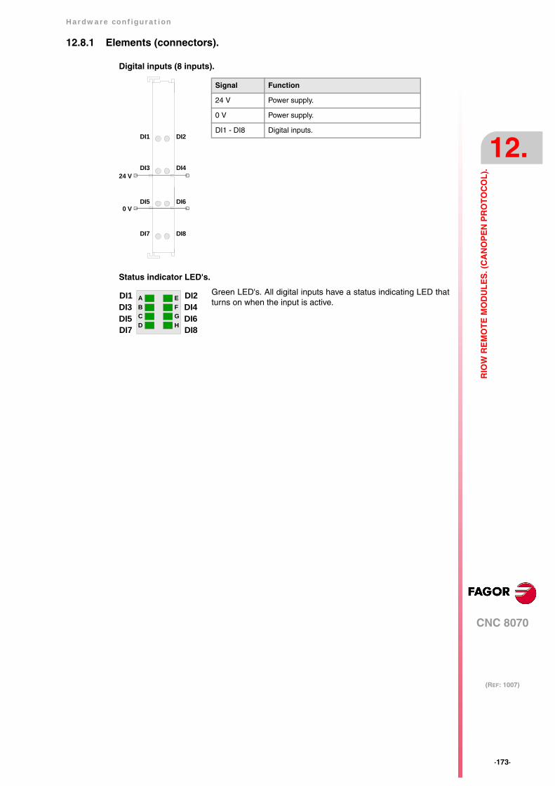
Hardware configuration
CNC 8070
12.
(REF: 1007)
·173·
RIO
W R
EM
OT
E M
OD
UL
ES
. (C
AN
OP
EN
PR
OT
OC
OL
).
12.8.1 Elements (connectors).
Digital inputs (8 inputs).
Status indicator LED's.
Green LED's. All digital inputs have a status indicating LED thatturns on when the input is active.
DI1
DI3
DI5
DI7
DI2
DI4
DI6
DI8
24 V
0 V
Signal Function
24 V Power supply.
0 V Power supply.
DI1 - DI8 Digital inputs.
ABCD
EFGH
DI1DI3DI5DI7
DI2DI4DI6DI8
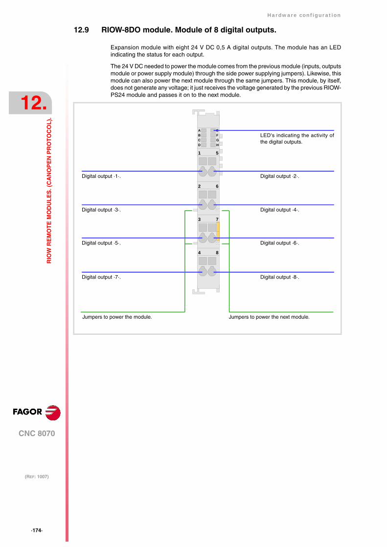
·174·
Hardware configuration
CNC 8070
12.
(REF: 1007)
RIO
W R
EM
OT
E M
OD
UL
ES
. (C
AN
OP
EN
PR
OT
OC
OL
).
12.9 RIOW-8DO module. Module of 8 digital outputs.
Expansion module with eight 24 V DC 0,5 A digital outputs. The module has an LEDindicating the status for each output.
The 24 V DC needed to power the module comes from the previous module (inputs, outputsmodule or power supply module) through the side power supplying jumpers). Likewise, thismodule can also power the next module through the same jumpers. This module, by itself,does not generate any voltage; it just receives the voltage generated by the previous RIOW-PS24 module and passes it on to the next module.
4 8
1 5
2 6
3 7
ABCD
EFGH
Digital output ·3·.
Digital output ·5·.
Digital output ·7·.
Digital output ·1·.
Digital output ·4·.
Digital output ·6·.
Digital output ·8·.
Digital output ·2·.
LED's indicating the activity ofthe digital outputs.
Jumpers to power the next module.Jumpers to power the module.

Hardware configuration
CNC 8070
12.
(REF: 1007)
·175·
RIO
W R
EM
OT
E M
OD
UL
ES
. (C
AN
OP
EN
PR
OT
OC
OL
).
12.9.1 Elements (connectors).
Digital outputs (8 outputs).
Status indicator LED's.
Green LED's. All digital outputs have a status indicating LED thatturns on when the output is active.
DO1
DO3
DO5
DO7
DO2
DO4
DO6
DO8
24 V
0 V
Signal Function
24 V Power supply.
0 V Power supply.
DO1 - DO8 Digital outputs.
ABCD
EFGH
DO1DO3DO5DO7
DO2DO4DO6DO8
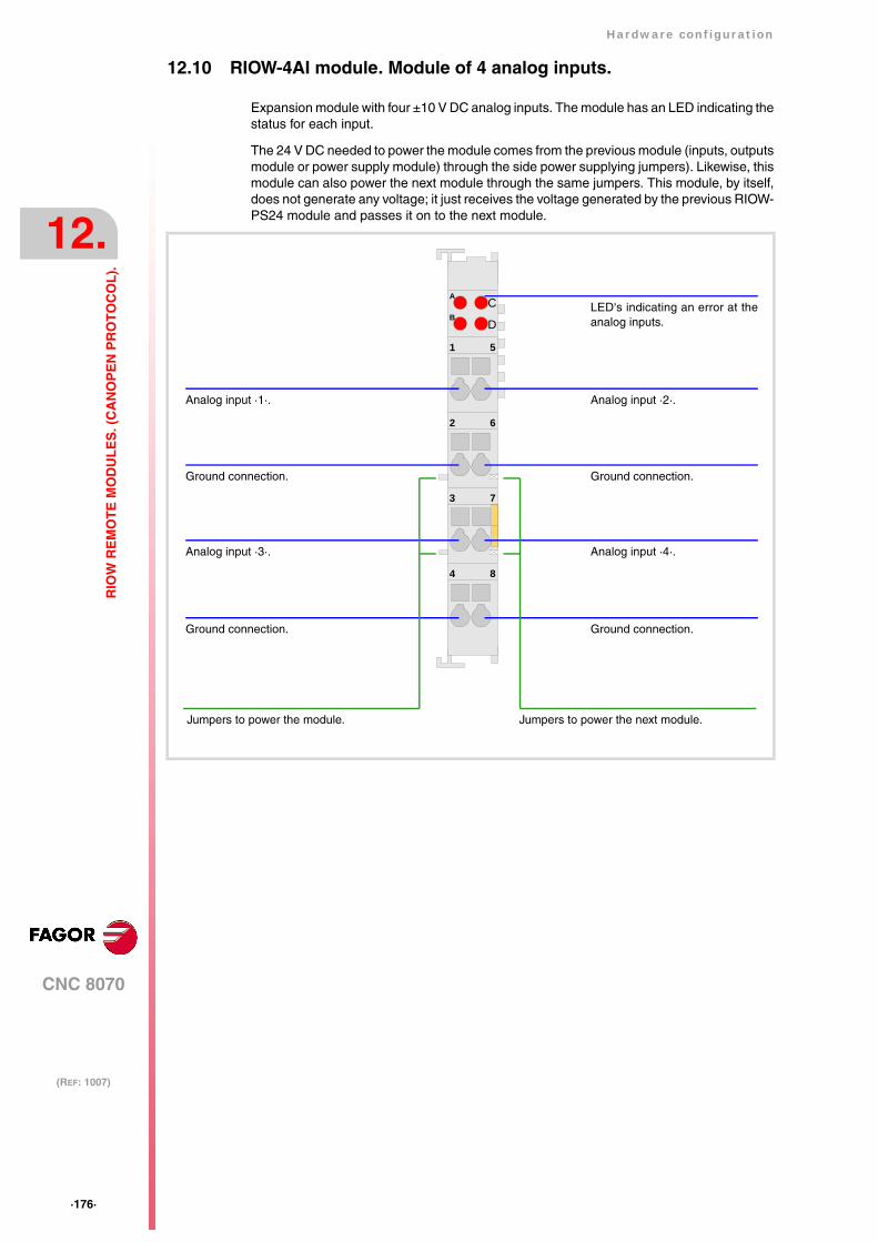
·176·
Hardware configuration
CNC 8070
12.
(REF: 1007)
RIO
W R
EM
OT
E M
OD
UL
ES
. (C
AN
OP
EN
PR
OT
OC
OL
).
12.10 RIOW-4AI module. Module of 4 analog inputs.
Expansion module with four ±10 V DC analog inputs. The module has an LED indicating thestatus for each input.
The 24 V DC needed to power the module comes from the previous module (inputs, outputsmodule or power supply module) through the side power supplying jumpers). Likewise, thismodule can also power the next module through the same jumpers. This module, by itself,does not generate any voltage; it just receives the voltage generated by the previous RIOW-PS24 module and passes it on to the next module.
4 8
1 5
2 6
3 7
CA
DB
Ground connection.
Analog input ·3·.
Ground connection.
Analog input ·1·.
Ground connection.
Analog input ·4·.
Ground connection.
Analog input ·2·.
LED's indicating an error at theanalog inputs.
Jumpers to power the next module.Jumpers to power the module.
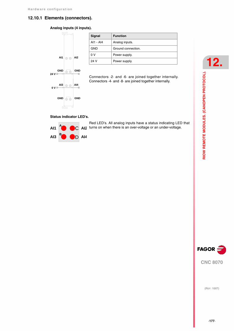
Hardware configuration
CNC 8070
12.
(REF: 1007)
·177·
RIO
W R
EM
OT
E M
OD
UL
ES
. (C
AN
OP
EN
PR
OT
OC
OL
).
12.10.1 Elements (connectors).
Analog inputs (4 inputs).
Status indicator LED's.
Red LED's. All analog inputs have a status indicating LED thatturns on when there is an over-voltage or an under-voltage.
AI1
GND
AI3
GND
AI2
GND
AI4
GND
24 V
0 V
Signal Function
AI1 - AI4 Analog inputs.
GND Ground connection.
0 V Power supply.
24 V Power supply.
Connectors ·2· and ·6· are joined together internally.Connectors ·4· and ·8· are joined together internally.
CA
DB
AI1
AI3
AI2
AI4
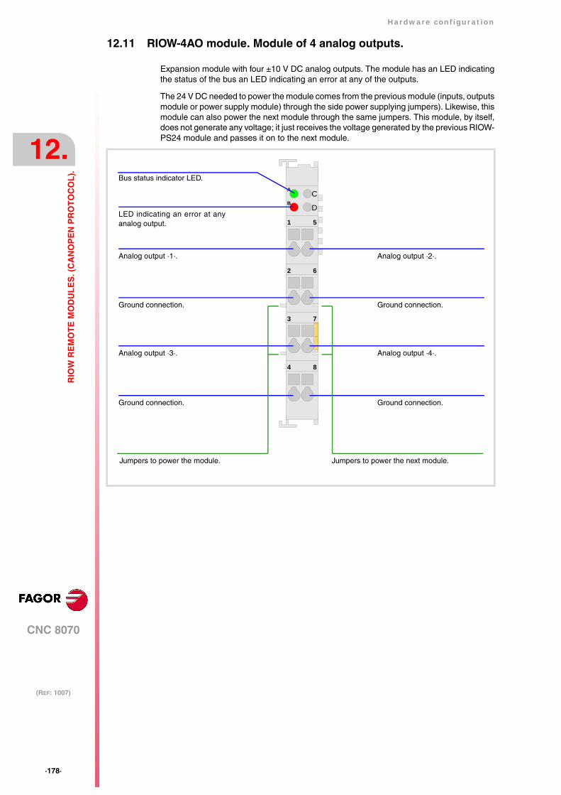
·178·
Hardware configuration
CNC 8070
12.
(REF: 1007)
RIO
W R
EM
OT
E M
OD
UL
ES
. (C
AN
OP
EN
PR
OT
OC
OL
).
12.11 RIOW-4AO module. Module of 4 analog outputs.
Expansion module with four ±10 V DC analog outputs. The module has an LED indicatingthe status of the bus an LED indicating an error at any of the outputs.
The 24 V DC needed to power the module comes from the previous module (inputs, outputsmodule or power supply module) through the side power supplying jumpers). Likewise, thismodule can also power the next module through the same jumpers. This module, by itself,does not generate any voltage; it just receives the voltage generated by the previous RIOW-PS24 module and passes it on to the next module.
4 8
1 5
2 6
3 7
CA
DB
Ground connection.
Analog output ·3·.
Ground connection.
Analog output ·1·.
Ground connection.
Analog output ·4·.
Ground connection.
Analog output ·2·.
Jumpers to power the next module.Jumpers to power the module.
Bus status indicator LED.
LED indicating an error at anyanalog output.

Hardware configuration
CNC 8070
12.
(REF: 1007)
·179·
RIO
W R
EM
OT
E M
OD
UL
ES
. (C
AN
OP
EN
PR
OT
OC
OL
).
12.11.1 Elements (connectors).
Analog outputs (4 outputs).
Led ·BUS·. Data bus status.
Led ·ERR·. Error at the outputs.
Green LED's. The LED turns on when transmission at the bus isOK.
Red LED's. The LED turns on if there is an overload or a short-circuit to ground at any of the outputs.
AO1
GND
AO3
GND
AO2
GND
AO4
GND
24 V
0 V
Signal Function
AO1 - AO4 Analog outputs.
GND Ground connection.
0 V Power supply.
24 V Power supply.
All ·GND· connectors are joined together internally.
CA
DB
BUS
ERR
CA
DB
BUS
ERR
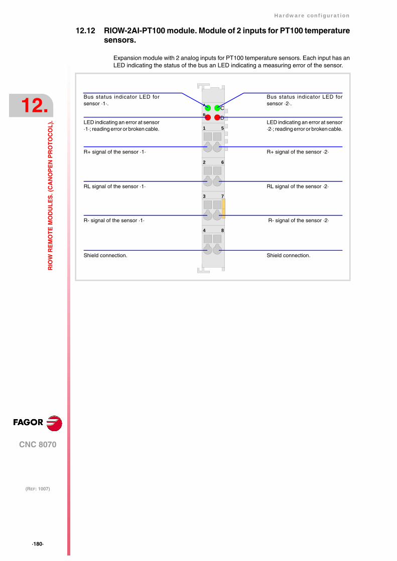
·180·
Hardware configuration
CNC 8070
12.
(REF: 1007)
RIO
W R
EM
OT
E M
OD
UL
ES
. (C
AN
OP
EN
PR
OT
OC
OL
).
12.12 RIOW-2AI-PT100 module. Module of 2 inputs for PT100 temperaturesensors.
Expansion module with 2 analog inputs for PT100 temperature sensors. Each input has anLED indicating the status of the bus an LED indicating a measuring error of the sensor.
4 8
1 5
2 6
3 7
CA
DB
RL signal of the sensor ·1·
R- signal of the sensor ·1·
Shield connection.
R+ signal of the sensor ·1·
RL signal of the sensor ·2·
R- signal of the sensor ·2·
Shield connection.
R+ signal of the sensor ·2·
Bus status indicator LED forsensor ·1·.
LED indicating an error at sensor·1·; reading error or broken cable.
Bus status indicator LED forsensor ·2·.
LED indicating an error at sensor·2·; reading error or broken cable.
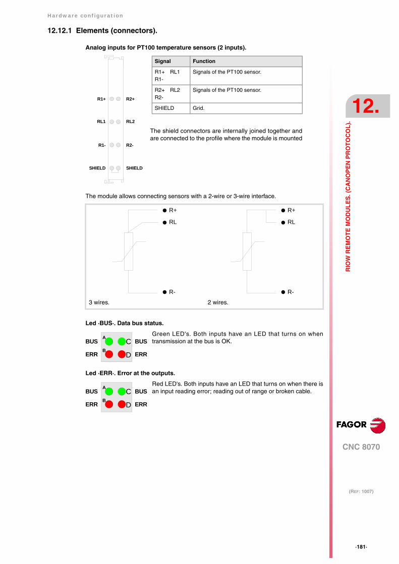
Hardware configuration
CNC 8070
12.
(REF: 1007)
·181·
RIO
W R
EM
OT
E M
OD
UL
ES
. (C
AN
OP
EN
PR
OT
OC
OL
).
12.12.1 Elements (connectors).
Analog inputs for PT100 temperature sensors (2 inputs).
The module allows connecting sensors with a 2-wire or 3-wire interface.
Led ·BUS·. Data bus status.
Led ·ERR·. Error at the outputs.
3 wires. 2 wires.
Green LED's. Both inputs have an LED that turns on whentransmission at the bus is OK.
Red LED's. Both inputs have an LED that turns on when there isan input reading error; reading out of range or broken cable.
R1+
RL1
R1-
SHIELD
R2+
RL2
R2-
SHIELD
Signal Function
R1+ RL1R1-
Signals of the PT100 sensor.
R2+ RL2R2-
Signals of the PT100 sensor.
SHIELD Grid.
The shield connectors are internally joined together andare connected to the profile where the module is mounted
R+
R-
RL
R+
R-
RL
CA
DB
BUS
ERR
BUS
ERR
CA
DB
BUS
ERR
BUS
ERR
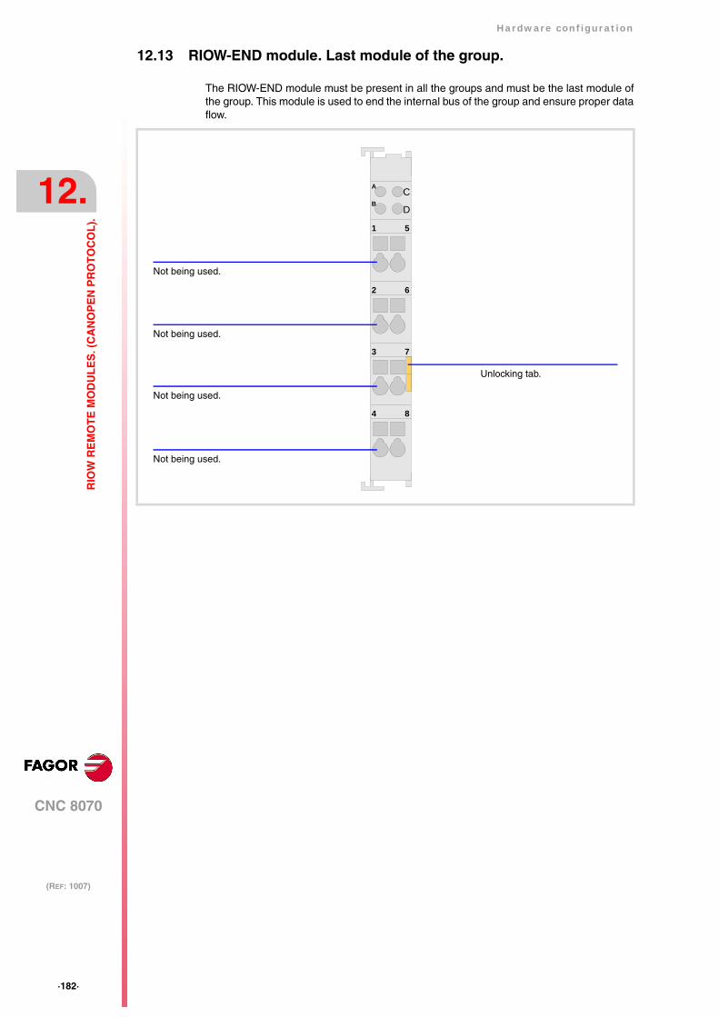
·182·
Hardware configuration
CNC 8070
12.
(REF: 1007)
RIO
W R
EM
OT
E M
OD
UL
ES
. (C
AN
OP
EN
PR
OT
OC
OL
).
12.13 RIOW-END module. Last module of the group.
The RIOW-END module must be present in all the groups and must be the last module ofthe group. This module is used to end the internal bus of the group and ensure proper dataflow.
4 8
1 5
2 6
3 7
CA
DB
Not being used.
Unlocking tab.
Not being used.
Not being used.
Not being used.
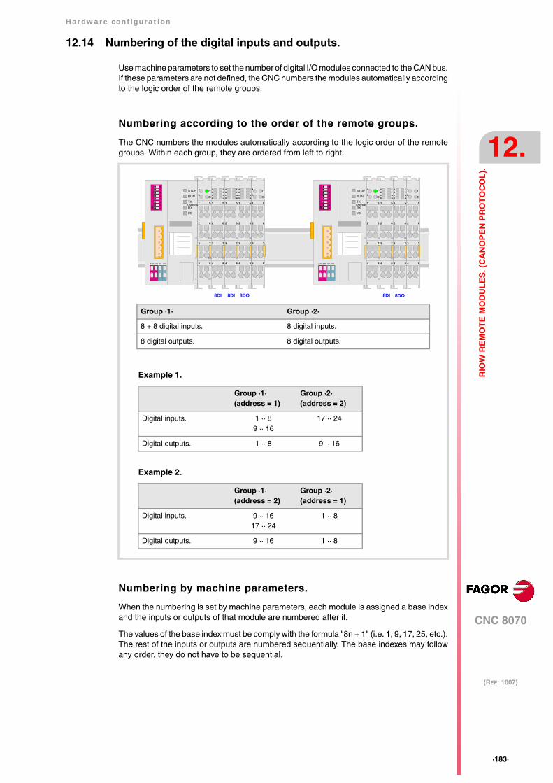
Hardware configuration
CNC 8070
12.
(REF: 1007)
·183·
RIO
W R
EM
OT
E M
OD
UL
ES
. (C
AN
OP
EN
PR
OT
OC
OL
).
12.14 Numbering of the digital inputs and outputs.
Use machine parameters to set the number of digital I/O modules connected to the CAN bus.If these parameters are not defined, the CNC numbers the modules automatically accordingto the logic order of the remote groups.
Numbering according to the order of the remote groups.
The CNC numbers the modules automatically according to the logic order of the remotegroups. Within each group, they are ordered from left to right.
Numbering by machine parameters.
When the numbering is set by machine parameters, each module is assigned a base indexand the inputs or outputs of that module are numbered after it.
The values of the base index must be comply with the formula "8n + 1" (i.e. 1, 9, 17, 25, etc.).The rest of the inputs or outputs are numbered sequentially. The base indexes may followany order, they do not have to be sequential.
Group ·1· Group ·2·
8 + 8 digital inputs. 8 digital inputs.
8 digital outputs. 8 digital outputs.
Example 1.
Group ·1·(address = 1)
Group ·2·(address = 2)
Digital inputs. 1 ·· 89 ·· 16
17 ·· 24
Digital outputs. 1 ·· 8 9 ·· 16
Example 2.
Group ·1·(address = 2)
Group ·2·(address = 1)
Digital inputs. 9 ·· 1617 ·· 24
1 ·· 8
Digital outputs. 9 ·· 16 1 ·· 8
STOP
RUN
TX
RX
I/O
Overflow
56
78
12
34
ON
24V 24V 0V 0V 4 8
1 5
2 6
3 7
CA
DB
4 8
1 5
2 6
3 7
ABCD
EFGH
4 8
1 5
2 6
3 7
ABCD
EFGH
8DI 8DI 8DO
4 8
1 5
2 6
3 7
ABCD
EFGH
4 8
1 5
2 6
3 7
CA
DB
STOP
RUN
TX
RX
I/O
Overflow
56
78
12
34
ON
24V 24V 0V 0V 4 8
1 5
2 6
3 7
CA
DB
4 8
1 5
2 6
3 7
ABCD
EFGH
4 8
1 5
2 6
3 7
ABCD
EFGH
8DI 8DO
4 8
1 5
2 6
3 7
CA
DB

·184·
Hardware configuration
CNC 8070
12.
(REF: 1007)
RIO
W R
EM
OT
E M
OD
UL
ES
. (C
AN
OP
EN
PR
OT
OC
OL
).
When inserting a new module, the first modules will be assigned the numbering of the tableand the last one will be assigned the next valid base index after the highest one assigneduntil then.
Examples for numbering the different modules.
Remote group (1).
Digital inputs Digital inputs
Base index Numbering Base index Numbering
module 1 1 1 ·· 8 81 81 ·· 88
module 2 33 33 ·· 40
Remote group (2).
Digital inputs Digital inputs
Base index Numbering Base index Numbering
module 1 113 113 ·· 120 49 49 ·· 56
STOP
RUN
TX
RX
I/O
Overflow
56
78
12
34
ON
24V 24V 0V 0V 4 8
1 5
2 6
3 7
CA
DB
4 8
1 5
2 6
3 7
ABCD
EFGH
4 8
1 5
2 6
3 7
ABCD
EFGH
8DI 8DI 8DO
4 8
1 5
2 6
3 7
ABCD
EFGH
4 8
1 5
2 6
3 7
CA
DB
STOP
RUN
TX
RX
I/O
Overflow
56
78
12
34
ON
24V 24V 0V 0V 4 8
1 5
2 6
3 7
CA
DB
4 8
1 5
2 6
3 7
ABCD
EFGH
4 8
1 5
2 6
3 7
ABCD
EFGH
8DI 8DO
4 8
1 5
2 6
3 7
CA
DB
GROUP = 2GROUP = 1

Hardware configuration
CNC 8070
12.
(REF: 1007)
·185·
RIO
W R
EM
OT
E M
OD
UL
ES
. (C
AN
OP
EN
PR
OT
OC
OL
).
12.15 Numbering of the analog inputs and outputs and of thetemperature sensor inputs.
The CNC numbers the modules automatically according to the logic order of the remotegroups. Within each group, they are ordered from left to right.
When numbering the analog inputs, the CNC considers the inputs for the temperature sensoras analog inputs. The CNC machine parameters must be set to indicate the number of PT100inputs and to which analog inputs they are connected. A PT100 input is active if it has oneof these temperature sensors connected to it. Refer to the installation manual for furtherdetail.
STOP
RUN
TX
RX
I/O
Overflow
56
78
12
34
ON
24V 24V 0V 0V 4 8
1 5
2 6
3 7
CA
DB
4AI 2AI 4AIPT100
GROUP = 2GROUP = 1
STOP
RUN
TX
RX
I/O
Overflow
56
78
12
34
ON
24V 24V 0V 0V 4 8
1 5
2 6
3 7
CA
DB
2AI
4 8
1 5
2 6
3 7
CA
DB
4 8
1 5
2 6
3 7
CA
DB
PT100
4 8
1 5
2 6
3 7
CA
DB
4 8
1 5
2 6
3 7
CA
DB
4 8
1 5
2 6
3 7
CA
DB
4 8
1 5
2 6
3 7
CA
DB
4 8
1 5
2 6
3 7
CA
DB
4AO
4 8
1 5
2 6
3 7
CA
DB
4AO
Group ·1· Group ·2·
4 + 4 analog inputs. 4 analog inputs.
4 analog inputs. 2 PT100 inputs.
2 PT100 inputs.
Example.
Group ·1·(address = 1)
Group ·2·(address = 2)
Analog inputs.PT100 inputs.Analog inputs.
1 ·· 45 ·· 6
7 ·· 10
11 ·· 12
Analog outputs. 1 ·· 4 5 ·· 8
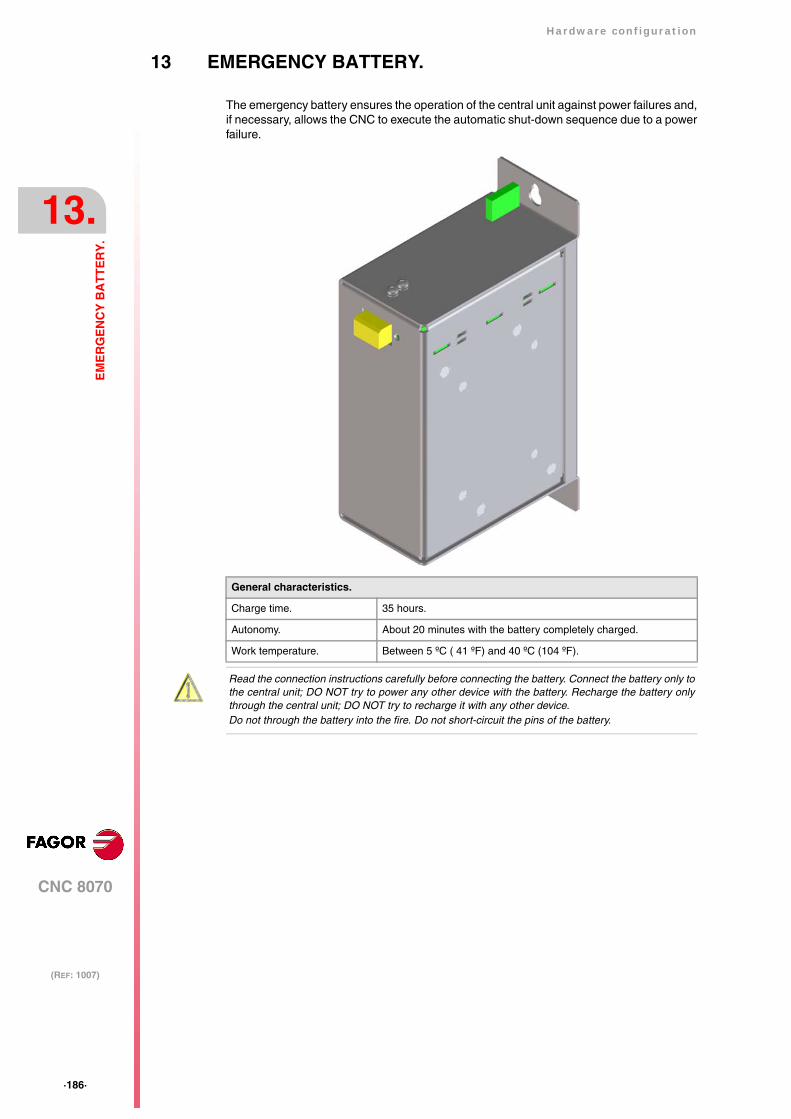
·186·
Hardware configuration
CNC 8070
13.
(REF: 1007)
EM
ER
GE
NC
Y B
AT
TE
RY
.
13 EMERGENCY BATTERY.
The emergency battery ensures the operation of the central unit against power failures and,if necessary, allows the CNC to execute the automatic shut-down sequence due to a powerfailure.
General characteristics.
Charge time. 35 hours.
Autonomy. About 20 minutes with the battery completely charged.
Work temperature. Between 5 ºC ( 41 ºF) and 40 ºC (104 ºF).
Read the connection instructions carefully before connecting the battery. Connect the battery only tothe central unit; DO NOT try to power any other device with the battery. Recharge the battery onlythrough the central unit; DO NOT try to recharge it with any other device.Do not through the battery into the fire. Do not short-circuit the pins of the battery.
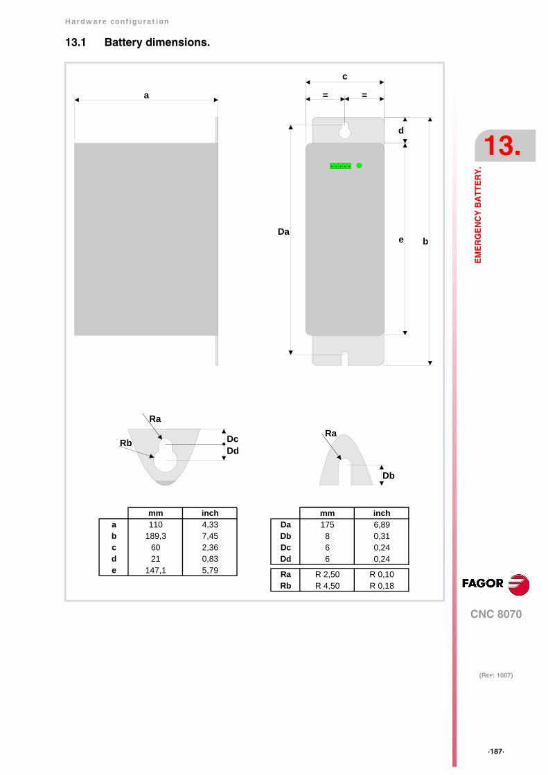
Hardware configuration
CNC 8070
13.
(REF: 1007)
·187·
EM
ER
GE
NC
Y B
AT
TE
RY
.
13.1 Battery dimensions.
a =
c
d
e b
Db
=
Da
Ra
Rb DcDd
Ra
mm incha 110 4,33b 189,3 7,45c 60 2,36d 21 0,83e 147,1 5,79
mm inchDa 175 6,89Db 8 0,31Dc 6 0,24Dd 6 0,24
Ra R 2,50 R 0,10Rb R 4,50 R 0,18

·188·
Hardware configuration
CNC 8070
13.
(REF: 1007)
EM
ER
GE
NC
Y B
AT
TE
RY
.
13.2 Connectors and connection.
Connector. Powering the central unit and charging the battery.
5-pin male Phoenix minicombicon contact (3.5 mm pitch).
The battery has a single connector to charge it and to power the CNC when necessary.
Status indicator LED.
The LED located next to the connector indicates the status of the battery. The LED blinkswhile the battery is being charged and it stays on when the battery is charged.
Connection to the central unit (ICU and MCU).
Connect all the pins of the battery to the central unit. The battery is charged from the centralunit; DO NOT use any other device to recharge it.
54321
Vbat -Vbat +ChassisVch +Vch - Signal Function
Vbat -Vbat +
Central unit powered by the battery.
Chassis Shield.
Vch -Vch +
Recharging the battery through the centralunit.
Vch -
Vbat +
Vbat -
ChassisVch +
Vch -
Vbat +
Vbat -
ChassisVch +
1
2
3
4
5
1
2
3
4
5
54321
Vbat -Vbat +ChassisVch +Vch -
5 4 3 2 1
Vba
t -V
bat +
Cha
ssis
Vch
+Vc
h -
ICU/MCU central unit Battery
Hardware configuration
CNC 8070
13.
(REF: 1007)
·189·
EM
ER
GE
NC
Y B
AT
TE
RY
.
13.3 Operation of the emergency battery.
Central unit powered by the battery.
The battery only powers the central unit when a failure occurs at the power supply (a dropof the 24 V). The Fagor battery provides an autonomy of about 20 minutes when it is fullycharged.
Response of the CNC with battery to mains failures.
When a power supply failure occurs (drop at the 24 V) and there is a battery connected tothe central unit, the latter responds as follows:
• If the supply is interrupted for less than 2 seconds.
The CNC shows the corresponding warning and the system recovers fine. Errors mayoccur at the CAN bus due to the lack of 24 V at the remote modules.
• If the supply is interrupted for more than 2 seconds.
After the 2 seconds, the CNC shows the corresponding error and it initiates the automaticshut-down sequence. First of all, the CNC stops any process in progress (program inexecution, tool change, etc.) and closes the CNC8070 application. Then, the CCN shutsthe whole system down and, finally, deactivates the battery.
Recharging the battery.
The battery is charged from the central unit; DO NOT use any other device to recharge it.The LED next to the connector blinks while the battery is being charged and it stays on whenthe battery is charged. The charging process takes about 35 hours.
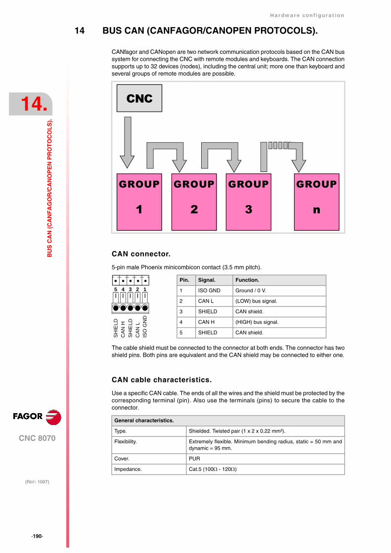
·190·
Hardware configuration
CNC 8070
14.
(REF: 1007)
BU
S C
AN
(C
AN
FA
GO
R/C
AN
OP
EN
PR
OT
OC
OL
S).
14 BUS CAN (CANFAGOR/CANOPEN PROTOCOLS).
CANfagor and CANopen are two network communication protocols based on the CAN bussystem for connecting the CNC with remote modules and keyboards. The CAN connectionsupports up to 32 devices (nodes), including the central unit; more one than keyboard andseveral groups of remote modules are possible.
CAN connector.
5-pin male Phoenix minicombicon contact (3.5 mm pitch).
The cable shield must be connected to the connector at both ends. The connector has twoshield pins. Both pins are equivalent and the CAN shield may be connected to either one.
CAN cable characteristics.
Use a specific CAN cable. The ends of all the wires and the shield must be protected by thecorresponding terminal (pin). Also use the terminals (pins) to secure the cable to theconnector.
General characteristics.
Type. Shielded. Twisted pair (1 x 2 x 0.22 mm²).
Flexibility. Extremely flexible. Minimum bending radius, static = 50 mm anddynamic = 95 mm.
Cover. PUR
Impedance. Cat.5 (100Ω - 120Ω)
CNC
GROUP
1
GROUP
2
GROUP
3
GROUP
n
Pin. Signal. Function.
1 ISO GND Ground / 0 V.
2 CAN L (LOW) bus signal.
3 SHIELD CAN shield.
4 CAN H (HIGH) bus signal.
5 SHIELD CAN shield.
12345
ISO
GN
DC
AN
LSH
IELD
CA
N H
SHIE
LD
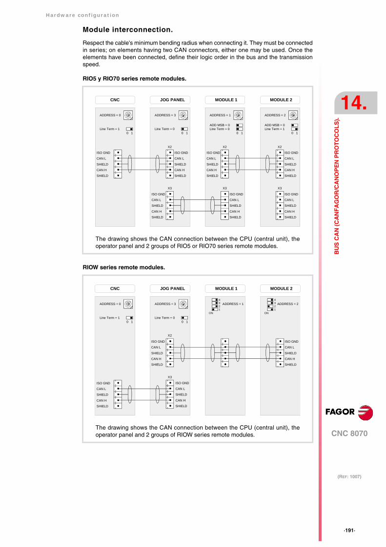
Hardware configuration
CNC 8070
14.
(REF: 1007)
·191·
BU
S C
AN
(C
AN
FA
GO
R/C
AN
OP
EN
PR
OT
OC
OL
S).
Module interconnection.
Respect the cable's minimum bending radius when connecting it. They must be connectedin series; on elements having two CAN connectors, either one may be used. Once theelements have been connected, define their logic order in the bus and the transmissionspeed.
RIO5 y RIO70 series remote modules.
RIOW series remote modules.
4
0F
DCB
98 7
5 3
1
1
JOG PANEL
X2
ADDRESS = 3
Line Term = 0
ISO GND
CAN L
SHIELD
CAN H
SHIELD
ISO GND
CAN L
SHIELD
CAN H
SHIELD
4
0F
DCB
98 7
5 3
1
1
MODULE 1
0
ADDRESS = 1
Line Term = 0
CNC
ISO GND
CAN L
SHIELD
CAN H
SHIELD
4
0F
DCB
98 7
5 3
1
1
MODULE 2
0
ADDRESS = 2
ISO GND
CAN L
SHIELD
CAN H
SHIELD
Line Term = 110
Line Term = 1
4
0F
DCB
98 7
5 3
1ADDRESS = 0
ISO GND
CAN L
SHIELD
CAN H
SHIELD
ISO GND
CAN L
SHIELD
CAN H
SHIELD
ISO GND
CAN L
SHIELD
CAN H
SHIELD
ADD MSB = 0 ADD MSB = 0
X3
X2
X3
X2
X3
0
The drawing shows the CAN connection between the CPU (central unit), theoperator panel and 2 groups of RIO5 or RIO70 series remote modules.
4
0F
DCB
98 7
5 3
1
1
JOG PANEL
ADDRESS = 3
Line Term = 0
MODULE 1
ADDRESS = 1
CNC MODULE 2
ADDRESS = 2
ISO GND
CAN L
SHIELD
CAN H
SHIELD
10Line Term = 1
4
0F
DCB
98 7
5 3
1ADDRESS = 0
X3
0
ISO GND
CAN L
SHIELD
CAN H
SHIELD
ISO GND
CAN L
SHIELD
CAN H
SHIELD
ISO GND
CAN L
SHIELD
CAN H
SHIELD
X2
4321
ON
4321
ON
The drawing shows the CAN connection between the CPU (central unit), theoperator panel and 2 groups of RIOW series remote modules.

·192·
Hardware configuration
CNC 8070
14.
(REF: 1007)
BU
S C
AN
(C
AN
FA
GO
R/C
AN
OP
EN
PR
OT
OC
OL
S).
14.1 Identification of the modules at the bus.
Each one of the elements integrated into the CAN bus is identified by its address or nodenumber. The CNC must always occupy position "0" and the rest of the elements of the buswill occupy consecutive positions starting with 1.
The node address or number also sets the priority of the group within the bus; the lower thenumber the higher the priority. We recommend to set the priority of the groups as follows(from highest to lowest).
• The groups that have the feedback inputs.
• The groups that have analog inputs and outputs.
• The groups that have digital inputs and outputs.
• The keyboard and jog panel.
Configuring the address (node number). Operator panel andRIO5 and RIO70 series remote modules.
·ADDRESS· selector. Address (node) of the element within the bus.
In order for any change at the "Address" switch to be assumed, the CNC must be restartedand the corresponding drive must be reset, however, we recommend to change the addresswhile the modules and the CNC are off.
The "Address" switch also sets the priority of the group within the bus; the lower the numberthe higher the priority. We recommend the keyboard and jog panel to be the last node of thebus.
·ADD MSB· selector Address (node) of the element within the bus.
With the ·4· switch (ADD MSB), the positions or elements integrated in the CAN bus maybe expanded up to 32. Positions 0-15 are selected with ADD MSB=0 and positions 16-31with ADD MSB=1.
Each one of the elements integrated into the CAN bus is identifiedby the 16-position rotary switch (0-15) "Address" (also referred toas "Node_Select"). With the ADD MSB" switch, the positions orelements integrated in the CAN bus may be expanded up to 32.
4
01FE
DCBA98 7 6 5 32
·CAN F/O· Address (node) of the element.
OFF Positions 0-15 within the bus.
ON Positions 16-31 within the bus.1 2 3 4ON
CAN
F/O
CO
BR
AD
D M
SB
ADDRESS 0 1 2 3 ··· 13 14 15
ADD MSB =0 0 1 2 3 ··· 13 14 15
ADD MSB =1 16 17 18 19 ··· 29 30 31
4
0F
DCB
98 7
5 3
1
10
ADDRESS = 2
ADD MSB = 1
4
0F
DCB
98 7
5 3
1
10
ADDRESS = 2
ADD MSB = 0
ADDRESS = 2 ADDRESS = 18
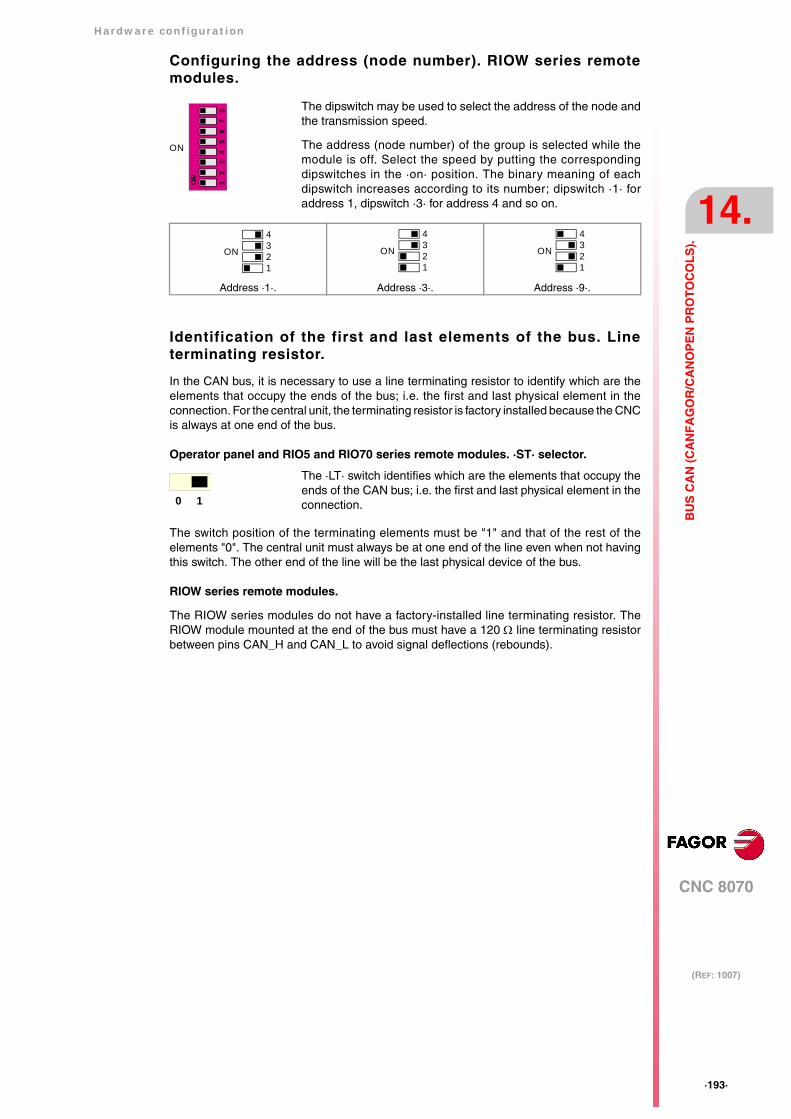
Hardware configuration
CNC 8070
14.
(REF: 1007)
·193·
BU
S C
AN
(C
AN
FA
GO
R/C
AN
OP
EN
PR
OT
OC
OL
S).
Configuring the address (node number). RIOW series remotemodules.
Identification of the first and last elements of the bus. Lineterminating resistor.
In the CAN bus, it is necessary to use a line terminating resistor to identify which are theelements that occupy the ends of the bus; i.e. the first and last physical element in theconnection. For the central unit, the terminating resistor is factory installed because the CNCis always at one end of the bus.
Operator panel and RIO5 and RIO70 series remote modules. ·ST· selector.
The switch position of the terminating elements must be "1" and that of the rest of theelements "0". The central unit must always be at one end of the line even when not havingthis switch. The other end of the line will be the last physical device of the bus.
RIOW series remote modules.
The RIOW series modules do not have a factory-installed line terminating resistor. TheRIOW module mounted at the end of the bus must have a 120 Ω line terminating resistorbetween pins CAN_H and CAN_L to avoid signal deflections (rebounds).
The dipswitch may be used to select the address of the node andthe transmission speed.
The address (node number) of the group is selected while themodule is off. Select the speed by putting the correspondingdipswitches in the ·on· position. The binary meaning of eachdipswitch increases according to its number; dipswitch ·1· foraddress 1, dipswitch ·3· for address 4 and so on.
Address ·1·. Address ·3·. Address ·9·.
The ·LT· switch identifies which are the elements that occupy theends of the CAN bus; i.e. the first and last physical element in theconnection.
56
78
12
34
ON
ON
4321
ON
4321
ON
4321
ON
0 1
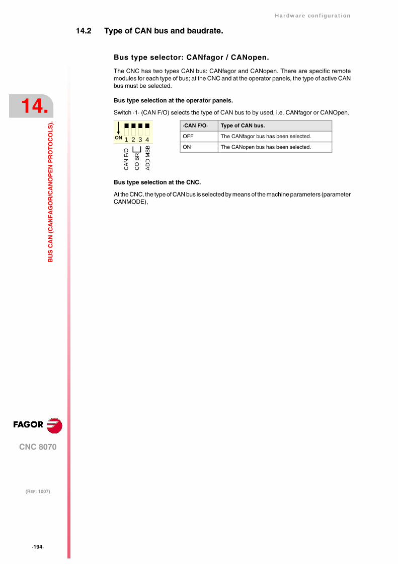
·194·
Hardware configuration
CNC 8070
14.
(REF: 1007)
BU
S C
AN
(C
AN
FA
GO
R/C
AN
OP
EN
PR
OT
OC
OL
S).
14.2 Type of CAN bus and baudrate.
Bus type selector: CANfagor / CANopen.
The CNC has two types CAN bus: CANfagor and CANopen. There are specific remotemodules for each type of bus; at the CNC and at the operator panels, the type of active CANbus must be selected.
Bus type selection at the operator panels.
Switch ·1· (CAN F/O) selects the type of CAN bus to by used, i.e. CANfagor or CANOpen.
Bus type selection at the CNC.
At the CNC, the type of CAN bus is selected by means of the machine parameters (parameterCANMODE),
·CAN F/O· Type of CAN bus.
OFF The CANfagor bus has been selected.
ON The CANopen bus has been selected.1 2 3 4ON
CAN
F/O
CO
BR
AD
D M
SB
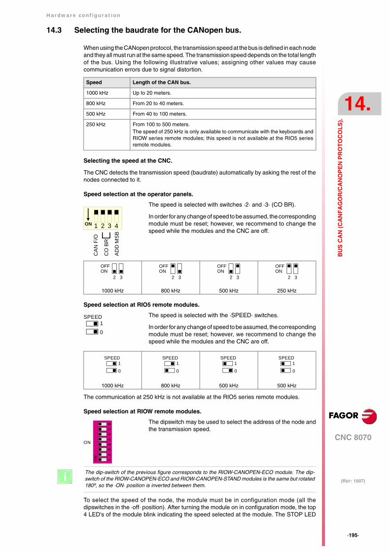
Hardware configuration
CNC 8070
14.
(REF: 1007)
·195·
BU
S C
AN
(C
AN
FA
GO
R/C
AN
OP
EN
PR
OT
OC
OL
S).
14.3 Selecting the baudrate for the CANopen bus.
When using the CANopen protocol, the transmission speed at the bus is defined in each nodeand they all must run at the same speed. The transmission speed depends on the total lengthof the bus. Using the following illustrative values; assigning other values may causecommunication errors due to signal distortion.
Selecting the speed at the CNC.
The CNC detects the transmission speed (baudrate) automatically by asking the rest of thenodes connected to it.
Speed selection at the operator panels.
Speed selection at RIO5 remote modules.
The communication at 250 kHz is not available at the RIO5 series remote modules.
Speed selection at RIOW remote modules.
To select the speed of the node, the module must be in configuration mode (all thedipswitches in the ·off· position). After turning the module on in configuration mode, the top4 LED's of the module blink indicating the speed selected at the module. The STOP LED
Speed Length of the CAN bus.
1000 kHz Up to 20 meters.
800 kHz From 20 to 40 meters.
500 kHz From 40 to 100 meters.
250 kHz From 100 to 500 meters.The speed of 250 kHz is only available to communicate with the keyboards andRIOW series remote modules; this speed is not available at the RIO5 seriesremote modules.
The speed is selected with switches ·2· and ·3· (CO BR).
In order for any change of speed to be assumed, the correspondingmodule must be reset; however, we recommend to change thespeed while the modules and the CNC are off.
1000 kHz 800 kHz 500 kHz 250 kHz
The speed is selected with the ·SPEED· switches.
In order for any change of speed to be assumed, the correspondingmodule must be reset; however, we recommend to change thespeed while the modules and the CNC are off.
1000 kHz 800 kHz 500 kHz 500 kHz
The dipswitch may be used to select the address of the node andthe transmission speed.
1 2 3 4ON
CAN
F/O
CO
BR
AD
D M
SB
2 3
OFFON
2 3
OFFON
2 3
OFFON
2 3ONOFF
SPEED10
SPEED10
10
SPEED10
SPEED10
SPEED
56
78
12
34
ON
ON
The dip-switch of the previous figure corresponds to the RIOW-CANOPEN-ECO module. The dip-switch of the RIOW-CANOPEN-ECO and RIOW-CANOPEN-STAND modules is the same but rotated180º, so the ·ON· position is inverted between them.
i

·196·
Hardware configuration
CNC 8070
14.
(REF: 1007)
BU
S C
AN
(C
AN
FA
GO
R/C
AN
OP
EN
PR
OT
OC
OL
S).
corresponds to dipswitch ·1·, the RUN to dipswitch ·2·, the TX to dipswitch ·3· and the RXto dipswitch ·4·. The first time the module is configured, the TX LED blinks indicating thatno valid speed has been selected.
The first 4 dipswitches are used to select the speed; the rest must be in the ·off· position.To select the speed, put the corresponding dipswitches in the ·on· position.
To save the selected speed, put dipswitch ·8· in the ·on· position. After saving theconfiguration, the corresponding LED's turn on to indicate the module speed. For 1 MHz,all four LED's turn on.
Once the speed has been selected, turn the module off by removing power and set dip-switch·8· in the ·off· position. Bear in mind that the next time the module is turned on, the positionof the dipswitches will indicate the address (node number) of the group.
If when turning the module on, all the dipswitches are not in the ·off· position, the position of thedipswitches will be the new address (node number) of the group. i
Dipswitch ·1· Dipswitch ·2· Dipswitch ·3· Dipswitch ·4· Speed
Off Off Off Off 1000 kHz
ON Off Off Off 800 kHz
Off ON Off Off 500 kHz
ON ON Off Off 250 kHz
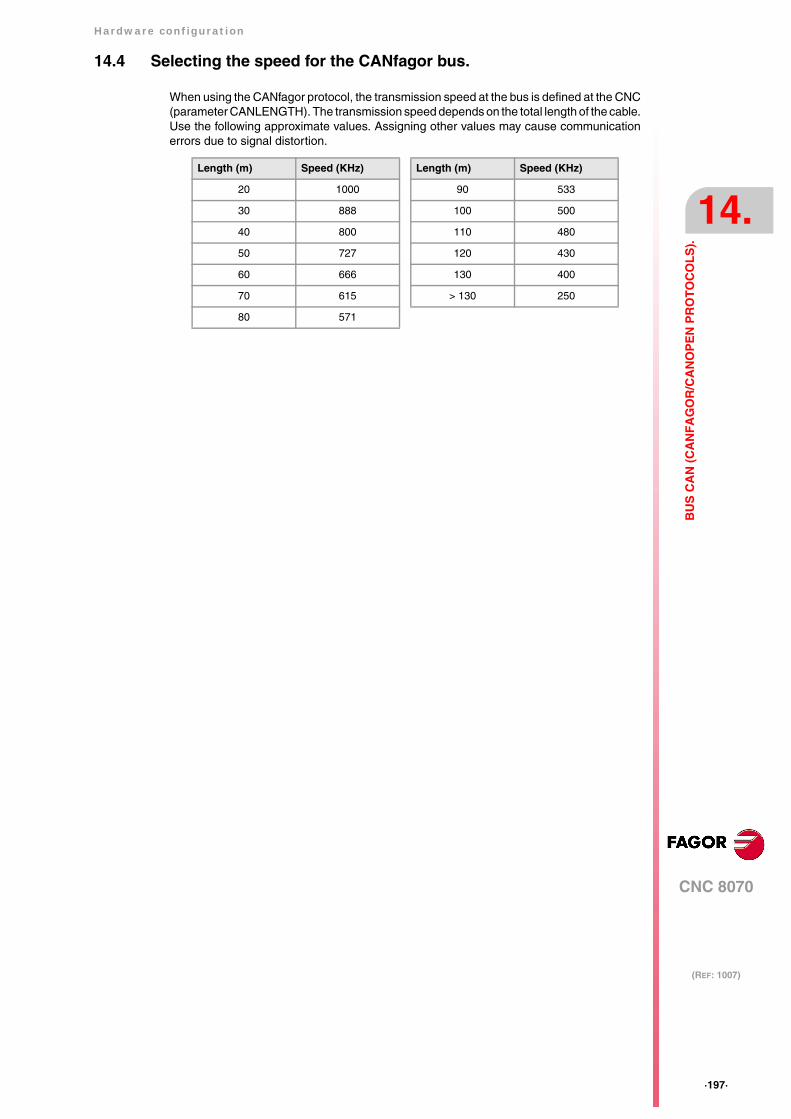
Hardware configuration
CNC 8070
14.
(REF: 1007)
·197·
BU
S C
AN
(C
AN
FA
GO
R/C
AN
OP
EN
PR
OT
OC
OL
S).
14.4 Selecting the speed for the CANfagor bus.
When using the CANfagor protocol, the transmission speed at the bus is defined at the CNC(parameter CANLENGTH). The transmission speed depends on the total length of the cable.Use the following approximate values. Assigning other values may cause communicationerrors due to signal distortion.
Length (m) Speed (KHz)
20 1000
30 888
40 800
50 727
60 666
70 615
80 571
Length (m) Speed (KHz)
90 533
100 500
110 480
120 430
130 400
> 130 250
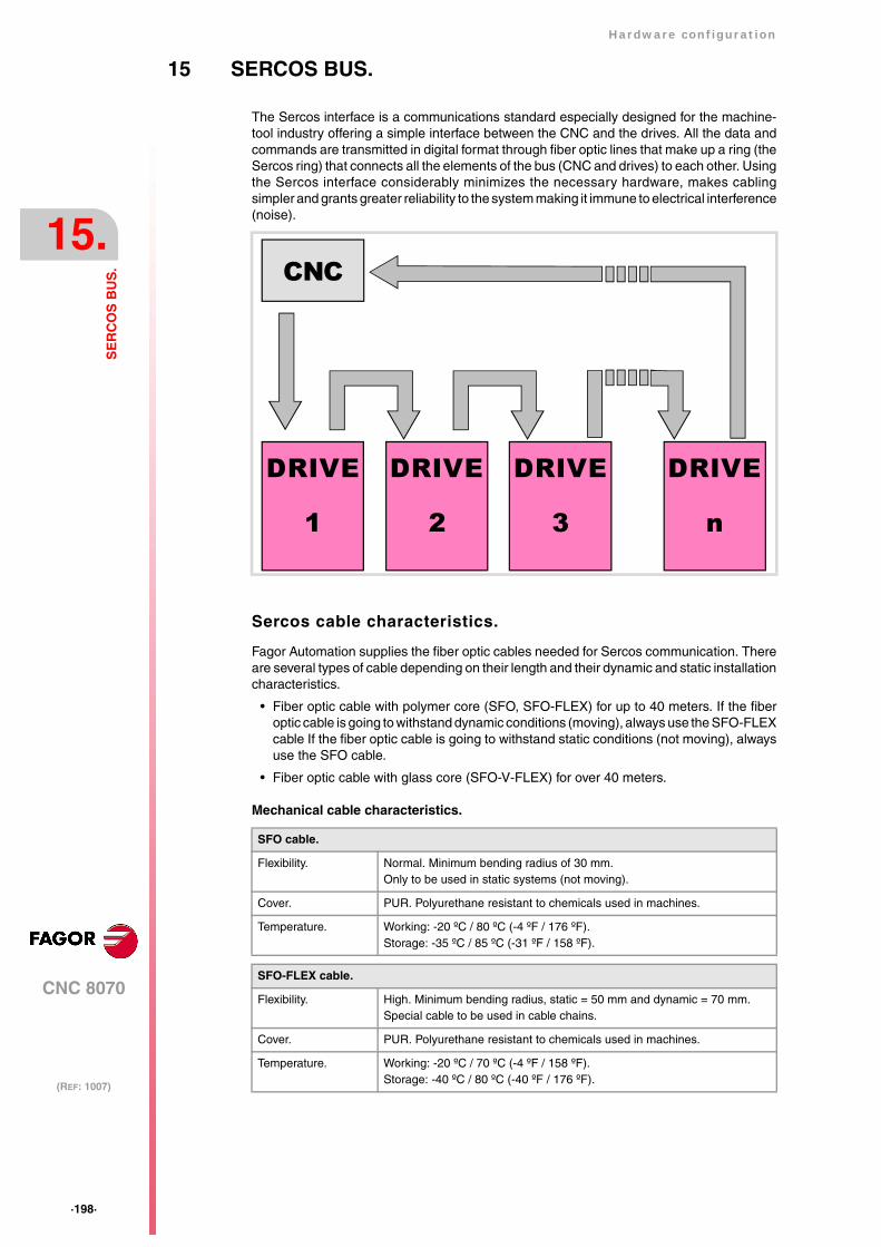
·198·
Hardware configuration
CNC 8070
15.
(REF: 1007)
SE
RC
OS
BU
S.
15 SERCOS BUS.
The Sercos interface is a communications standard especially designed for the machine-tool industry offering a simple interface between the CNC and the drives. All the data andcommands are transmitted in digital format through fiber optic lines that make up a ring (theSercos ring) that connects all the elements of the bus (CNC and drives) to each other. Usingthe Sercos interface considerably minimizes the necessary hardware, makes cablingsimpler and grants greater reliability to the system making it immune to electrical interference(noise).
Sercos cable characteristics.
Fagor Automation supplies the fiber optic cables needed for Sercos communication. Thereare several types of cable depending on their length and their dynamic and static installationcharacteristics.
• Fiber optic cable with polymer core (SFO, SFO-FLEX) for up to 40 meters. If the fiberoptic cable is going to withstand dynamic conditions (moving), always use the SFO-FLEXcable If the fiber optic cable is going to withstand static conditions (not moving), alwaysuse the SFO cable.
• Fiber optic cable with glass core (SFO-V-FLEX) for over 40 meters.
Mechanical cable characteristics.
SFO cable.
Flexibility. Normal. Minimum bending radius of 30 mm.Only to be used in static systems (not moving).
Cover. PUR. Polyurethane resistant to chemicals used in machines.
Temperature. Working: -20 ºC / 80 ºC (-4 ºF / 176 ºF).Storage: -35 ºC / 85 ºC (-31 ºF / 158 ºF).
SFO-FLEX cable.
Flexibility. High. Minimum bending radius, static = 50 mm and dynamic = 70 mm.Special cable to be used in cable chains.
Cover. PUR. Polyurethane resistant to chemicals used in machines.
Temperature. Working: -20 ºC / 70 ºC (-4 ºF / 158 ºF).Storage: -40 ºC / 80 ºC (-40 ºF / 176 ºF).
CNC
DRIVE
1
DRIVE
2
DRIVE
3
DRIVE
n
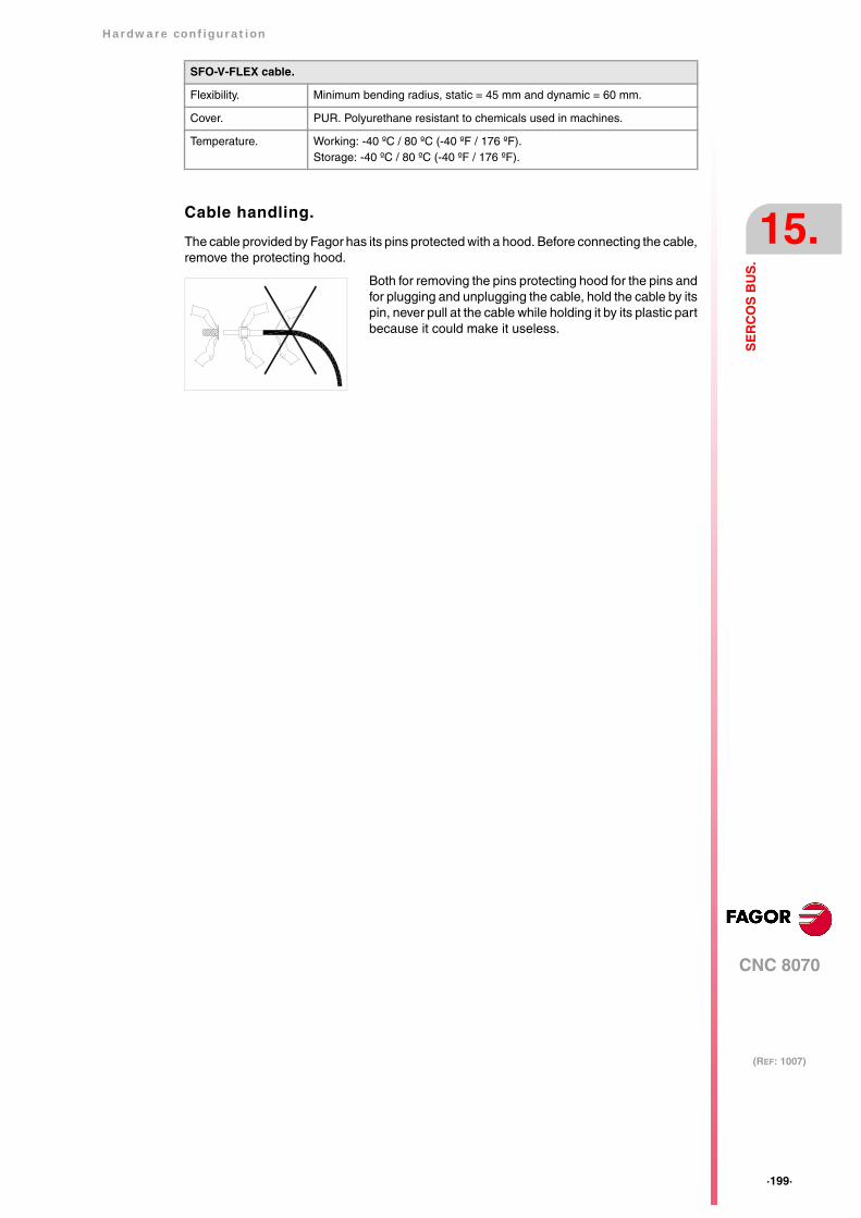
Hardware configuration
CNC 8070
15.
(REF: 1007)
·199·
SE
RC
OS
BU
S.
Cable handling.
The cable provided by Fagor has its pins protected with a hood. Before connecting the cable,remove the protecting hood.
SFO-V-FLEX cable.
Flexibility. Minimum bending radius, static = 45 mm and dynamic = 60 mm.
Cover. PUR. Polyurethane resistant to chemicals used in machines.
Temperature. Working: -40 ºC / 80 ºC (-40 ºF / 176 ºF).Storage: -40 ºC / 80 ºC (-40 ºF / 176 ºF).
Both for removing the pins protecting hood for the pins andfor plugging and unplugging the cable, hold the cable by itspin, never pull at the cable while holding it by its plastic partbecause it could make it useless.

·200·
Hardware configuration
CNC 8070
15.
(REF: 1007)
SE
RC
OS
BU
S.
15.1 Module identification and connection
Module identification.
The CNC (except the ICU and MCU models) and the drives are identified with the 16-bit rotaryswitch "Address" (also called "Node_Select"). This switch selects the address (node)occupied by each of the elements integrated into the Sercos connection. Some CNC's (likethe ICU and MCU models) do not have the switch; they are pre-configured to always occupyposition ·0· at the bus.
The CNC must always occupy position 0 and the drives will occupy consecutive positionsstarting with 1. In order for any change at the "Address" switch to be assumed, thecorresponding drive must be reset and the CNC powered off and back on.
Whether the drive identified with number 1 (for example) corresponds to the X axis, to theY axis or to another one is irrelevant. However, it is a good idea, for clarity sake, that themachine axes X, Y, Z, U, V, W, A, B and C be assigned consecutive numbers in that order.
Module interconnection.
The Sercos connection is carried out in a ring using fiber optic cable by joining an OUTterminal with an IN terminal. The drawing shows the Sercos connection of the CNC withFagor spindle drives and the X, Y axes.
Then set certain CNC machine parameters to configure the connection. i
4
0F
EDCBA98 7 6 5 321
OUT
IN
4
01
FEDCBA98 7 6 5 32
Node = 0
CNCC
40F
EDBA98 7 6 5 321
Node = 3
SPINDLE
4
0FEDCBA9
8 7 6 5 321
Node = 1
X AXIS
4
0FEDCBA9
8 7 6 5 321
Node = 2
Y AXIS
4
8
5
0F
EDCBA97 6 321
45
C
3
0F
EDBA98 7 6 21
4
0F
C
5 3
1
EDBA98 7 6 2
OUT
IN
OUT
IN
OUT
IN

Hardware configuration
CNC 8070
15.
(REF: 1007)
·201·
SE
RC
OS
BU
S.
15.2 Data exchange via Sercos.
The data exchange between the CNC and the drives takes place in each position loop. Themore data is exchanged, the more overloaded the Sercos transmission will be. Theseregisters should be limited leaving only the ones absolutely necessary after the setup.
There is data that must necessarily be transmitted in every position loop (velocity commands,feedback, etc.) and other data that may be transmitted in several loops (monitoring, etc.).Since the CNC must know the priority of those transmissions, there must be two separatetransmission channels.
Cyclic channel (fast).
The data is transmitted in every position loop. It contains velocity commands, feedback, etc.Each variable that is read or written at the drive is included in this data pack. In order notto overload the interface, you must limit the number of drive variables involved to theminimum necessary.
Indicate the type of data to be transmitted. The data to be sent to the drives must be placedin certain particular registers of the PLC and the data to be read from the drives is receivedin other registers of the PLC.
Service channel (slow).
The data is transmitted in several position loops. It contains monitoring data, etc.
This channel can only be accessed through high-level blocks in the part-program or fromthe PLC channel.
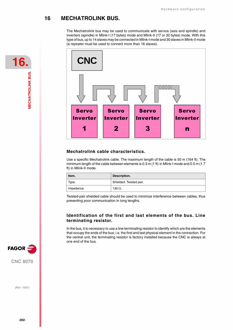
·202·
Hardware configuration
CNC 8070
16.
(REF: 1007)
ME
CH
AT
RO
LIN
K B
US
.
16 MECHATROLINK BUS.
The Mechatrolink bus may be used to communicate with servos (axis and spindle) andinverters (spindle) in Mlink-I (17 bytes) mode and Mlink-II (17 or 32 bytes) mode. With thistype of bus, up to 14 slaves may be connected in Mlink-I mode and 30 slaves in Mlink-II mode(a repeater must be used to connect more than 16 slaves).
Mechatrolink cable characteristics.
Use a specific Mechatrolink cable. The maximum length of the cable is 50 m (164 ft). Theminimum length of the cable between elements is 0.3 m (1 ft) in Mlink-I mode and 0.5 m (1.7ft) in Mlink-II mode.
Twisted-pair shielded cable should be used to minimize interference between cables, thuspreventing poor communication in long lengths.
Identification of the first and last elements of the bus. Lineterminating resistor.
In the bus, it is necessary to use a line terminating resistor to identify which are the elementsthat occupy the ends of the bus; i.e. the first and last physical element in the connection. Forthe central unit, the terminating resistor is factory installed because the CNC is always atone end of the bus.
Item. Description.
Type. Shielded. Twisted pair.
Impedance. 130 Ω.
ServoInverter
1 2 3 n
CNC
ServoInverter
ServoInverter
ServoInverter

Hardware configuration
CNC 8070
16.
(REF: 1007)
·203·
ME
CH
AT
RO
LIN
K B
US
.
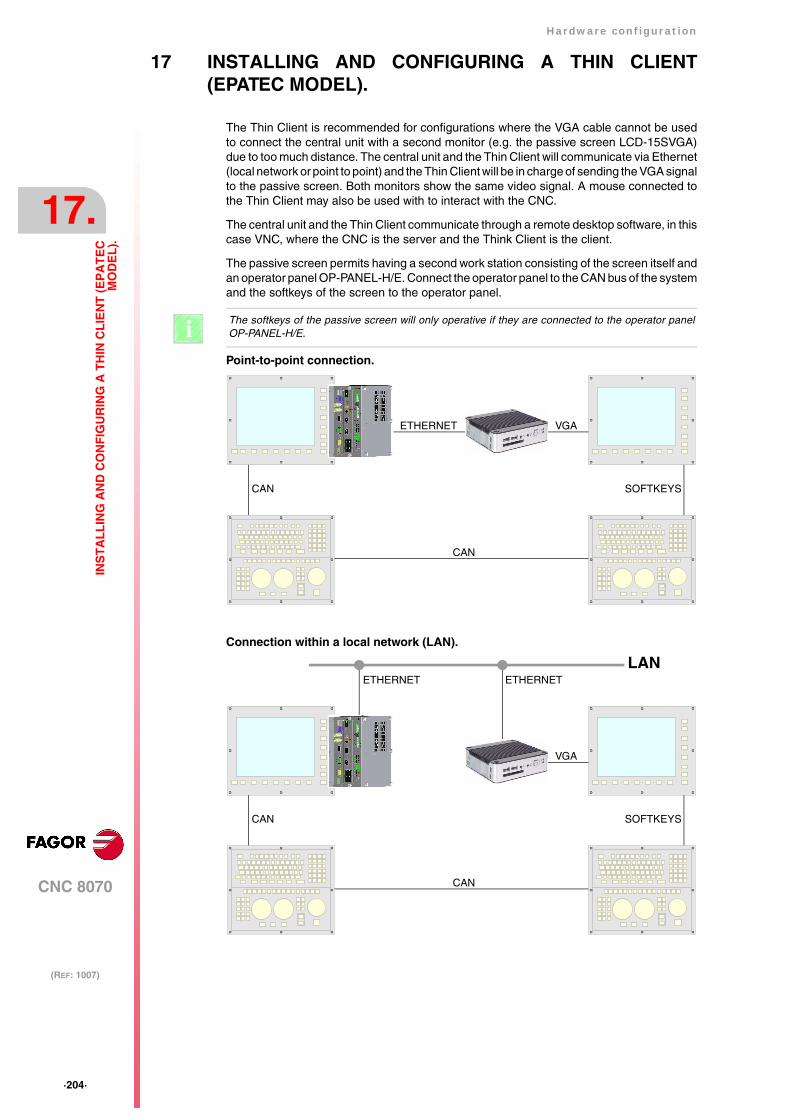
·204·
Hardware configuration
CNC 8070
17.
(REF: 1007)
INS
TA
LL
ING
AN
D C
ON
FIG
UR
ING
A T
HIN
CL
IEN
T (
EP
AT
EC
MO
DE
L).
17 INSTALLING AND CONFIGURING A THIN CLIENT(EPATEC MODEL).
The Thin Client is recommended for configurations where the VGA cable cannot be usedto connect the central unit with a second monitor (e.g. the passive screen LCD-15SVGA)due to too much distance. The central unit and the Thin Client will communicate via Ethernet(local network or point to point) and the Thin Client will be in charge of sending the VGA signalto the passive screen. Both monitors show the same video signal. A mouse connected tothe Thin Client may also be used with to interact with the CNC.
The central unit and the Thin Client communicate through a remote desktop software, in thiscase VNC, where the CNC is the server and the Think Client is the client.
The passive screen permits having a second work station consisting of the screen itself andan operator panel OP-PANEL-H/E. Connect the operator panel to the CAN bus of the systemand the softkeys of the screen to the operator panel.
The softkeys of the passive screen will only operative if they are connected to the operator panelOP-PANEL-H/E. iPoint-to-point connection.
Connection within a local network (LAN).
VGA
CAN
ETHERNET
CAN
SOFTKEYS
VGA
CAN
ETHERNET
CAN
SOFTKEYS
LANETHERNET
Hardware configuration
CNC 8070
17.
(REF: 1007)
·205·
INS
TA
LL
ING
AN
D C
ON
FIG
UR
ING
A T
HIN
CL
IEN
T (
EP
AT
EC
MO
DE
L).
Cable characteristics.
A cross cable must be used when connecting the Thin Client directly to the CNC (point-to-point connection). A standard 10BASE-T shielded cable must be used when connecting theThin Client to a switch or within a local network. In either case, use a specific Ethernet cable.
In order to ensure proper performance, the connection cable must be inserted all the wayinto the connectors so they're latched. This ensures that the cable is properly latched anddoes not come off due to vibration.
Ethernet cable.
Type. Twisted pair. Shielded.
Impedance. Cat.5 (100Ω - 120Ω) or greater.
Maximum length. 100 meters (328 ft).
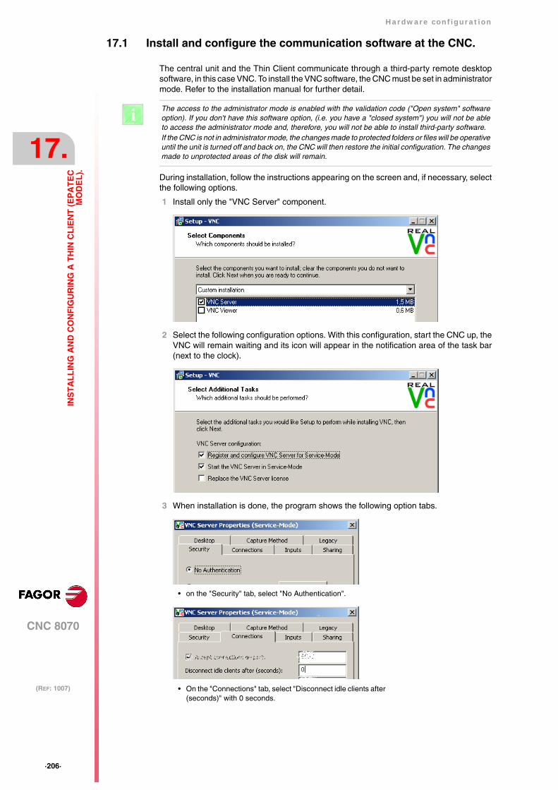
·206·
Hardware configuration
CNC 8070
17.
(REF: 1007)
INS
TA
LL
ING
AN
D C
ON
FIG
UR
ING
A T
HIN
CL
IEN
T (
EP
AT
EC
MO
DE
L).
17.1 Install and configure the communication software at the CNC.
The central unit and the Thin Client communicate through a third-party remote desktopsoftware, in this case VNC. To install the VNC software, the CNC must be set in administratormode. Refer to the installation manual for further detail.
During installation, follow the instructions appearing on the screen and, if necessary, selectthe following options.
1 Install only the "VNC Server" component.
2 Select the following configuration options. With this configuration, start the CNC up, theVNC will remain waiting and its icon will appear in the notification area of the task bar(next to the clock).
3 When installation is done, the program shows the following option tabs.
The access to the administrator mode is enabled with the validation code ("Open system" softwareoption). If you don't have this software option, (i.e. you have a "closed system") you will not be ableto access the administrator mode and, therefore, you will not be able to install third-party software.If the CNC is not in administrator mode, the changes made to protected folders or files will be operativeuntil the unit is turned off and back on, the CNC will then restore the initial configuration. The changesmade to unprotected areas of the disk will remain.
i
• on the "Security" tab, select "No Authentication".
• On the "Connections" tab, select "Disconnect idle clients after(seconds)" with 0 seconds.

Hardware configuration
CNC 8070
17.
(REF: 1007)
·207·
INS
TA
LL
ING
AN
D C
ON
FIG
UR
ING
A T
HIN
CL
IEN
T (
EP
AT
EC
MO
DE
L).
• On the "Inputs" tab, de-select the options "Accept keyboardevents from clients" and "Accept clipboard updates fromclients".
• The option "Accept pointer events from clients" is only takeninto account when a mouse is connected to the Thin Client.When selecting this option, the Thin Client sends mouseevents to the CNC.
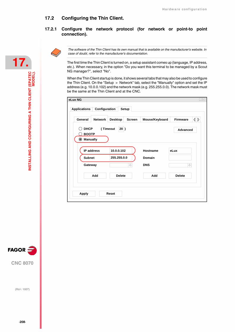
·208·
Hardware configuration
CNC 8070
17.
(REF: 1007)
INS
TA
LL
ING
AN
D C
ON
FIG
UR
ING
A T
HIN
CL
IEN
T (
EP
AT
EC
MO
DE
L).
17.2 Configuring the Thin Client.
17.2.1 Configure the network protocol (for network or point-to pointconnection).
The first time the Thin Client is turned on, a setup assistant comes up (language, IP address,etc.). When necessary, in the option "Do you want this terminal to be managed by a ScoutNG manager?", select "No".
When the Thin Client startup is done, it shows several tabs that may also be used to configurethe Thin Client. On the "Setup > Network" tab, select the "Manually" option and set the IPaddress (e.g. 10.0.0.102) and the network mask (e.g. 255.255.0.0). The network mask mustbe the same at the Thin Client and at the CNC.
The software of the Thin Client has its own manual that is available on the manufacturer's website. Incase of doubt, refer to the manufacturer's documentation.
eLux NG
Apply Reset
SetupConfigurationApplications
General Desktop Screen Mouse/Keyboard FirmwareNetwork
DHCPBOOTPManually
Advanced
Add Delete Add Delete
IP address
Subnet
Gateway
( Timeout 20 )
10.0.0.102
255.255.0.0
Hostname
Domain
DNS
eLux

Hardware configuration
CNC 8070
17.
(REF: 1007)
·209·
INS
TA
LL
ING
AN
D C
ON
FIG
UR
ING
A T
HIN
CL
IEN
T (
EP
AT
EC
MO
DE
L).
17.2.2 Configure the communication between the CNC and the Thin Client.
The Thin Client comes with a VNC client software. To configure the VNC start command,select the tab Configuration> New > Local and define the following data.
Together with the command, it launches the IP address to which the Thin Client is connected.The address may be changed from Configuration > Edit > Local, in the Parameter window.
Name VNC (or the desired name)
Application Custom
Parameter vncviewer10.0.7.250:0 -fullscreen (IP address of the CNC)
Start automatically Select this option with a value of 5 s (illustrative value).
Application restart Select this option so the Thin Client tries to re-establishcommunication without having to restart the system in case ofcommunication loss for some time (because the Ethernet cablehas been disconnected, for example).
The purpose of the "Start automatically" parameter is to start the VNC client of the Thin Client afterthe VNC of the CNC has been started up. The value of this parameter depends largely on how bothdevices, central unit and Thin Client, start up. If both elements start up at the same time or the ThinClient starts before the VNC server is available at the CNC, the VNC customer of the Thin Client cannotbe connected and it will issue a connection error or data reading error. In this case, the time set forparameter "Start automatically" will have to be increased. If the startup of the Thin Client depends on the CNC being started up first (e.g. condition the startupof the Thin Client to a PLC output), this "Start automatically" parameter could be set to 0 (zero).
i
eLux NG
Apply
Finish
Name
Application
vnc
0.0.7.250:0-fullscreen
Local
Custom
Start automatically afterDesktop icon
Application restartHidden
5 s
Parameter

·210·
Hardware configuration
CNC 8070
17.
(REF: 1007)
INS
TA
LL
ING
AN
D C
ON
FIG
UR
ING
A T
HIN
CL
IEN
T (
EP
AT
EC
MO
DE
L).
17.2.3 Configuring the startup of the Thin Client.
The BIOS must be modified in order for the Thin Client to start up automatically whenpowered on, without having to press the ON button. Having the Thin Client OFF, connect theexternal keyboard and, while starting up, press the [DEL] key to access the BIOS. The rightside of the BIOS shows a menu with the instructions to browse through the BIOS.
• Once in the BIOS, select "Advanced > APM configuration" and access the optionsmenu.
• Inside the menu "APM configuration", set the "Restore on AC/Power Loss" to [Power On].
• Get out of the BIOS saving the changes.
The BIOS is an essential part in the operation of the Thin Client. Do not change any other parameterof the BIOS. The wrong manipulation of the BIOS parameters may render it useless. i
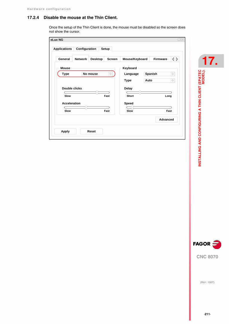
Hardware configuration
CNC 8070
17.
(REF: 1007)
·211·
INS
TA
LL
ING
AN
D C
ON
FIG
UR
ING
A T
HIN
CL
IEN
T (
EP
AT
EC
MO
DE
L).
17.2.4 Disable the mouse at the Thin Client.
Once the setup of the Thin Client is done, the mouse must be disabled so the screen doesnot show the cursor.
eLux NG
Apply Reset
SetupConfigurationApplications
General Desktop Screen Mouse/Keyboard FirmwareNetwork
Advanced
Mouse Keyboard
Language Spanish
Type Auto
Delay
Short Long
Speed
Slow Fast
Type No mouse
Double clicks
Slow Fast
Acceleration
Slow Fast

·212·
Hardware configuration
CNC 8070
17.
(REF: 1007)
INS
TA
LL
ING
AN
D C
ON
FIG
UR
ING
A T
HIN
CL
IEN
T (
EP
AT
EC
MO
DE
L).