Embed Size (px)
Citation preview
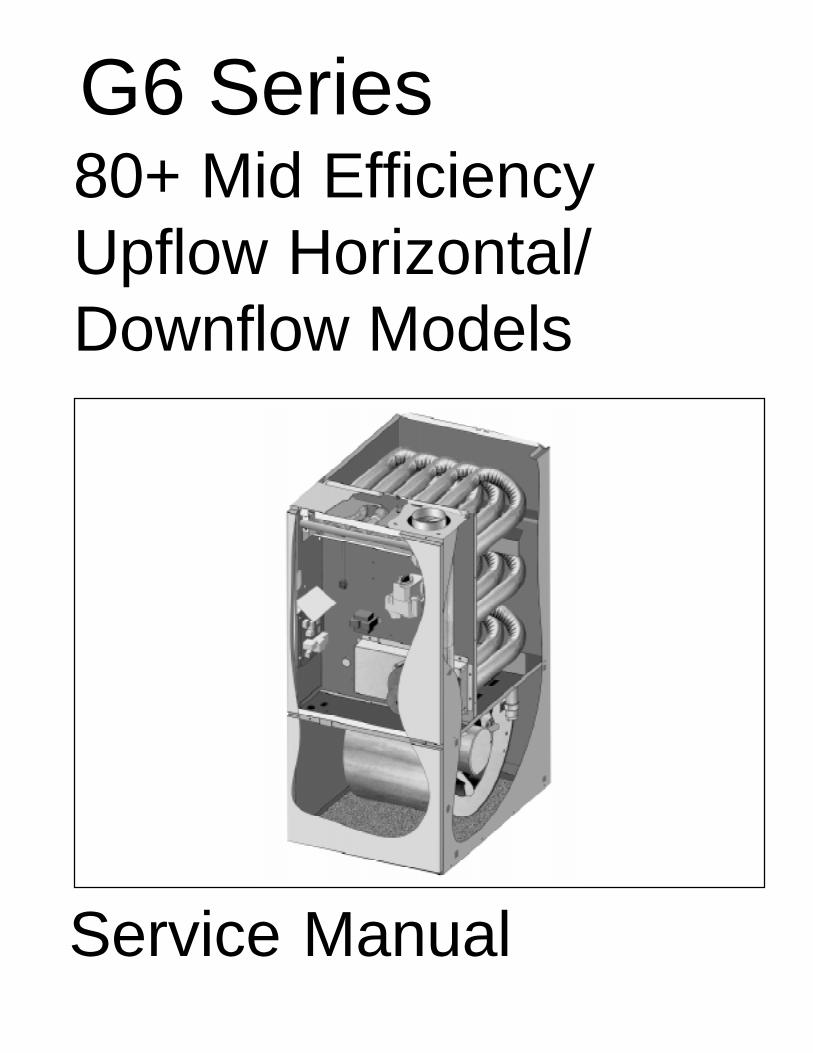
G6 Series80+ Mid EfficiencyUpflow Horizontal/Downflow Models
Service Manual

G6RA, G6RK Service Manual 1
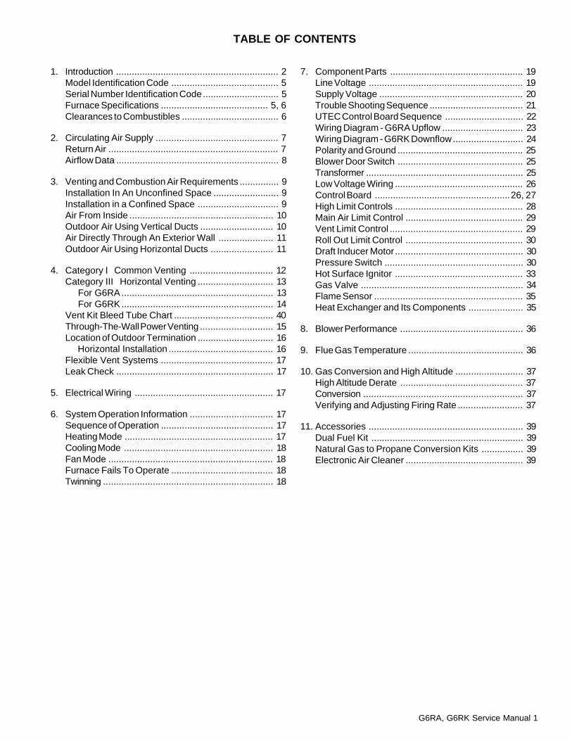
1. Introduction .............................................................. 2Model Identification Code ......................................... 5Serial Number Identification Code............................. 5Furnace Specifications ......................................... 5, 6Clearances to Combustibles ..................................... 6
2. Circulating Air Supply ............................................... 7Return Air ................................................................. 7Airflow Data .............................................................. 8
3. Venting and Combustion Air Requirements ............... 9Installation In An Unconfined Space ......................... 9Installation in a Confined Space ............................... 9Air From Inside ....................................................... 10Outdoor Air Using Vertical Ducts ............................ 10Air Directly Through An Exterior Wall ..................... 11Outdoor Air Using Horizontal Ducts ........................ 11
4. Category I Common Venting ................................ 12Category III Horizontal Venting ............................. 13 For G6RA.......................................................... 13 For G6RK.......................................................... 14Vent Kit Bleed Tube Chart ...................................... 40Through-The-Wall Power Venting ............................ 15Location of Outdoor Termination ............................. 16 Horizontal Installation ........................................ 16Flexible Vent Systems ........................................... 17Leak Check ............................................................ 17
5. Electrical Wiring ..................................................... 17
6. System Operation Information ................................ 17Sequence of Operation ........................................... 17Heating Mode ......................................................... 17Cooling Mode ......................................................... 18Fan Mode ............................................................... 18Furnace Fails To Operate ....................................... 18Twinning ................................................................. 18
TABLE OF CONTENTS
7. Component Parts ................................................... 19Line Voltage ........................................................... 19Supply Voltage ....................................................... 20Trouble Shooting Sequence .................................... 21UTEC Control Board Sequence .............................. 22Wiring Diagram - G6RA Upflow ............................... 23Wiring Diagram - G6RK Downflow........................... 24Polarity and Ground ................................................ 25Blower Door Switch ................................................ 25Transformer ............................................................ 25Low Voltage Wiring ................................................. 26Control Board ....................................................26, 27High Limit Controls ................................................. 28Main Air Limit Control ............................................. 29Vent Limit Control ................................................... 29Roll Out Limit Control ............................................. 30Draft Inducer Motor................................................. 30Pressure Switch ..................................................... 30Hot Surface Ignitor ................................................. 33Gas Valve .............................................................. 34Flame Sensor ......................................................... 35Heat Exchanger and Its Components ..................... 35
8. Blower Performance ............................................... 36
9. Flue Gas Temperature ............................................ 36
10. Gas Conversion and High Altitude .......................... 37High Altitude Derate ............................................... 37Conversion ............................................................. 37Verifying and Adjusting Firing Rate ......................... 37
11. Accessories ........................................................... 39Dual Fuel Kit .......................................................... 39Natural Gas to Propane Conversion Kits ................ 39Electronic Air Cleaner ............................................. 39
2 G6RA, G6RK Service Manual
INTRODUCTION
This service manual is designed to be used in conjunction with the installation manual provided witheach furnace.
This furnace represents the very latest in mid efficiency gas furnace technology. Consequently, certaincontrols within the furnace consist of highly sophisticated electronic components which are not userserviceable. Therefore, it is essential that only competent, qualified service personnel attempt toinstall, service, or maintain this product.
This service manual was written to assist the professional HVAC service technician to quickly andaccurately diagnose and repair any malfunctions of this product.
This service manual covers both upflow/horizontal models and downflow models installed asCategory I and Category III applications. The overall operation of all these models is basically the samewith the exception of certain controls that are unique to a particular model.
This manual, therefore, will deal with all subjects in a general nature (I.E. all text will pertain to allmodels) unless that subject is unique to a particular model or family, in which case it will be soindicated.
It will be necessary then for you to accurately identify the unit you are servicing, so you may be certainof the approved diagnosis and repair. (See Unit Identification on Page 4.)
This manual was prepared by the senior Technical Service and Communication Departments.
The information contained in this manual is intended for use by a qualified service technician who isfamiliar with the safety procedures required in installation and repair and who is equipped with theproper tools and testing instruments.
Installations and repairs made by unqualified persons can result in hazards subjecting the unqualifiedperson making such repairs to the risk of injury or electrical shock which can be serious or even fatalnot only to them, but also to persons being served by the equipment.
If you install or perform service on equipment, you must assume responsibility for any bodily injury orproperty damage which may result to you or others. We will not be responsible for any injury or propertydamage arising from improper installation, service, and/or service procedures.
WARNING!
G6RA, G6RK Service Manual 3
Furnace Dimensions ShippingInput A B C Flue Outlet Weight D
Model (Btuh) (in.) (in.) (in.) (in.) (lbs) (IN.)
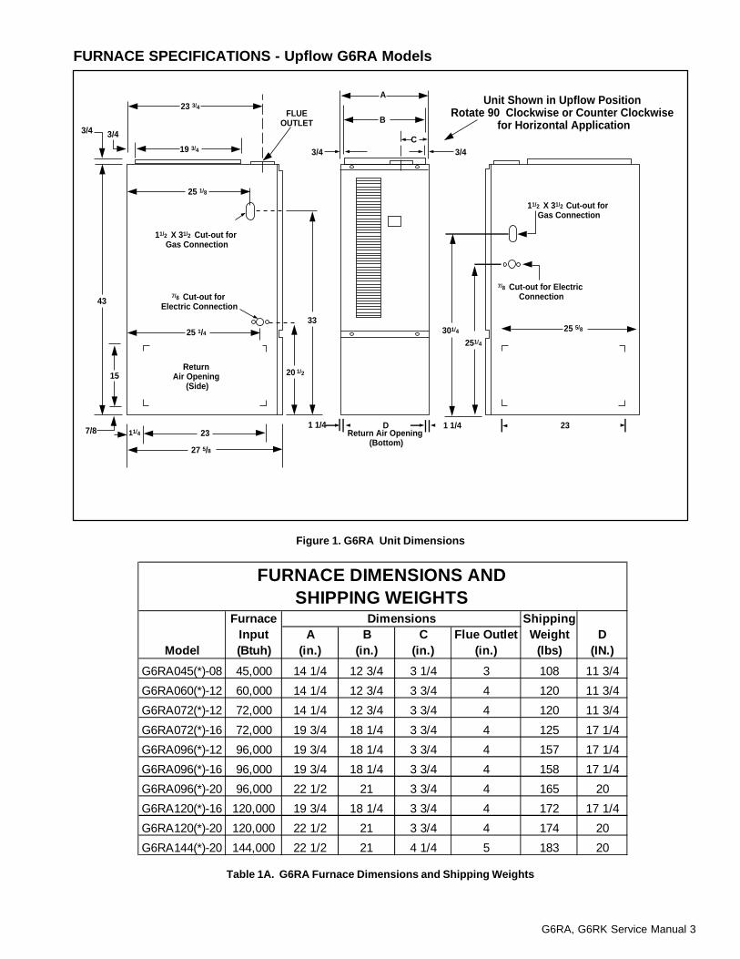
G6RA045(*)-08 45,000 14 1/4 12 3/4 3 1/4 3 108 11 3/4
G6RA060(*)-12 60,000 14 1/4 12 3/4 3 3/4 4 120 11 3/4
G6RA072(*)-12 72,000 14 1/4 12 3/4 3 3/4 4 120 11 3/4
G6RA072(*)-16 72,000 19 3/4 18 1/4 3 3/4 4 125 17 1/4
G6RA096(*)-12 96,000 19 3/4 18 1/4 3 3/4 4 157 17 1/4
G6RA096(*)-16 96,000 19 3/4 18 1/4 3 3/4 4 158 17 1/4
G6RA096(*)-20 96,000 22 1/2 21 3 3/4 4 165 20
G6RA120(*)-16 120,000 19 3/4 18 1/4 3 3/4 4 172 17 1/4
G6RA120(*)-20 120,000 22 1/2 21 3 3/4 4 174 20
G6RA144(*)-20 144,000 22 1/2 21 4 1/4 5 183 20
FURNACE DIMENSIONS ANDSHIPPING WEIGHTS
Unit Shown in Upflow Position Rotate 90 Clockwise or Counter Clockwise
for Horizontal Application
23 3/4
19 3/4
3/4
43
25 1/8
25 1/4 25 5/8
23
27 5/8
15 20 1/2
251/4
33301/4
A
B
C
FLUEOUTLET
11/2 X 31/2 Cut-out for Gas Connection
3/4 3/4
11/4
3/4
7/8 Cut-out for Electric Connection
11/2 X 31/2 Cut-out for Gas Connection
7/8 Cut-out for Electric Connection
Return Air Opening
(Side)
1 1/4 1 1/4D 23Return Air Opening
(Bottom)7/8
FURNACE SPECIFICATIONS - Upflow G6RA Models
Figure 1. G6RA Unit Dimensions
Table 1A. G6RA Furnace Dimensions and Shipping Weights
4 G6RA, G6RK Service Manual
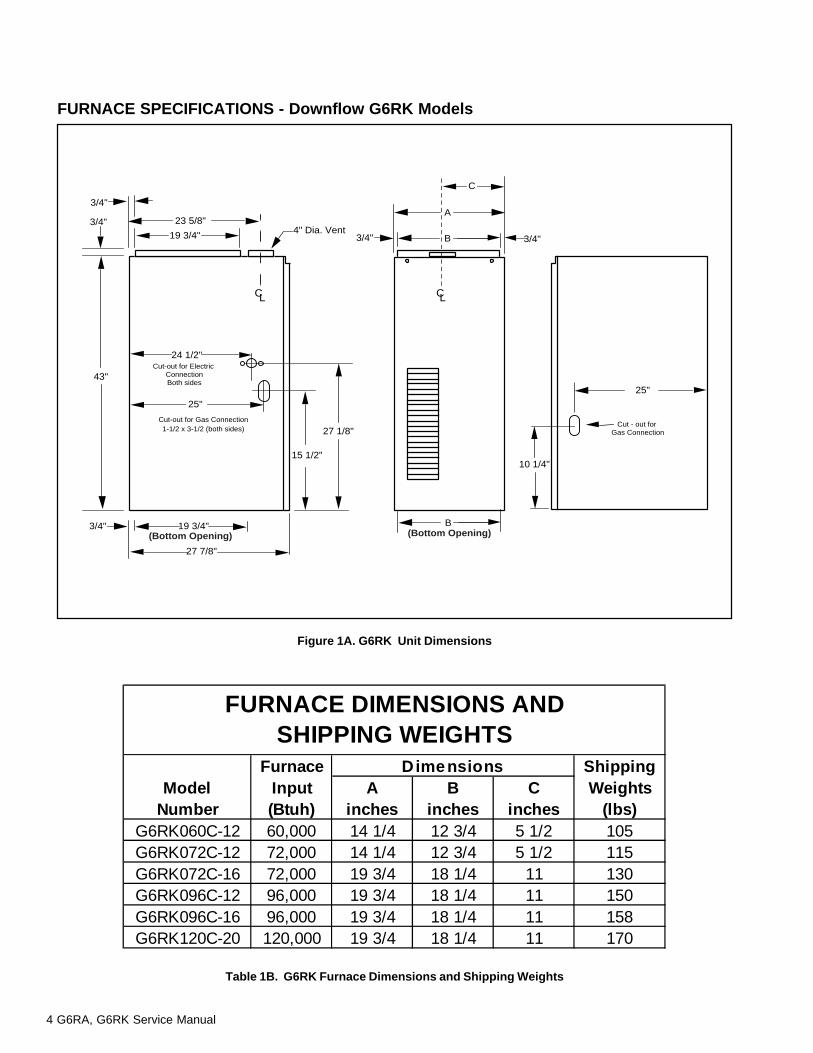
FURNACE SPECIFICATIONS - Downflow G6RK Models
Figure 1A. G6RK Unit Dimensions
Cut-out for Electric ConnectionBoth sides
Cut-out for Gas Connection1-1/2 x 3-1/2 (both sides)
27 7/8"
3/4" 19 3/4"
23 5/8"
19 3/4" 3/4"
C
CL
3/4"
3/4"
43"
4" Dia. Vent
Cut - out for Gas Connection
A
B
B
24 1/2"
25"
15 1/2"
27 1/8"
25"
3/4"
CL
(Bottom Opening)(Bottom Opening)
10 1/4"
Table 1B. G6RK Furnace Dimensions and Shipping Weights
Furnace ShippingModel Input A B C Weights
Number (Btuh) inches inches inches (lbs)G6RK060C-12 60,000 14 1/4 12 3/4 5 1/2 105G6RK072C-12 72,000 14 1/4 12 3/4 5 1/2 115G6RK072C-16 72,000 19 3/4 18 1/4 11 130G6RK096C-12 96,000 19 3/4 18 1/4 11 150G6RK096C-16 96,000 19 3/4 18 1/4 11 158G6RK120C-20 120,000 19 3/4 18 1/4 11 170
FURNACE DIMENSIONS ANDSHIPPING WEIGHTS
Dimensions
G6RA, G6RK Service Manual 5
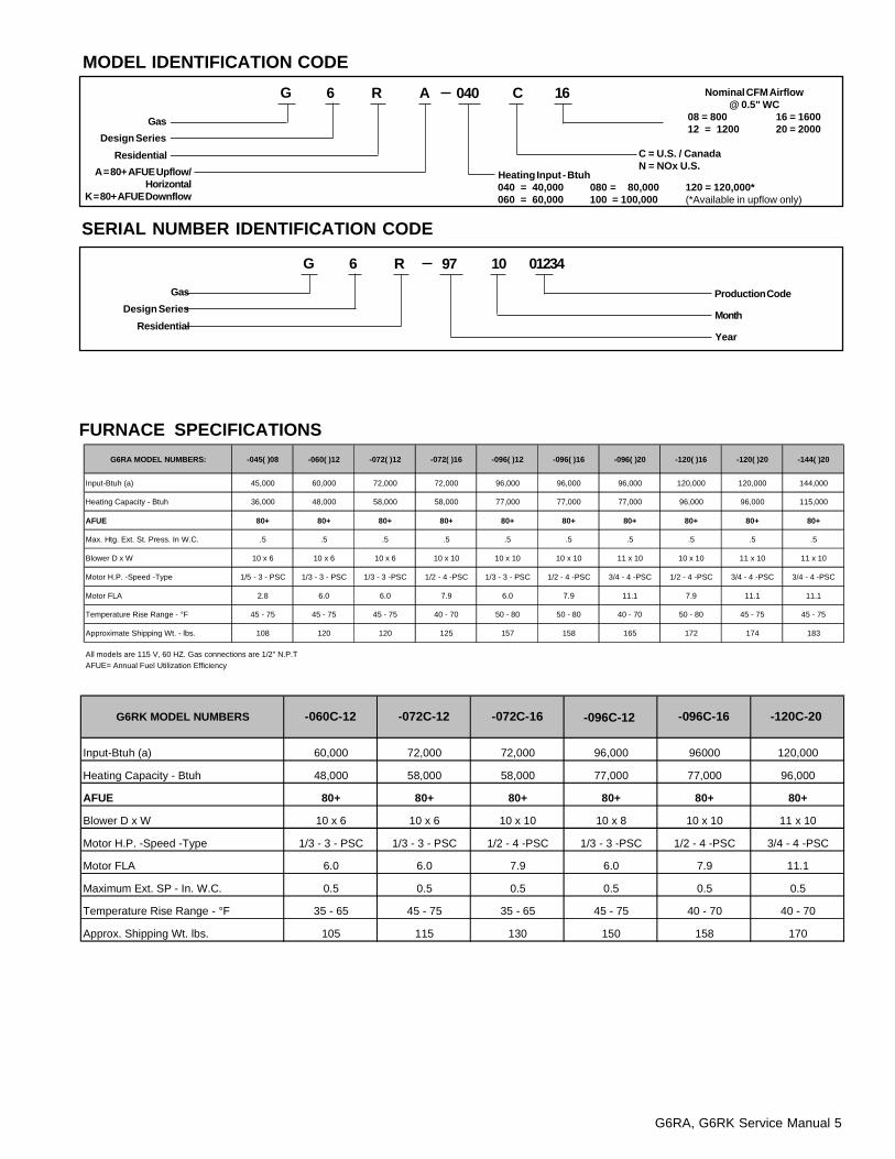
MODEL IDENTIFICATION CODE
SERIAL NUMBER IDENTIFICATION CODE
Nominal CFM Airflow@ 0.5" WC
08 = 800 16 = 160012 = 1200 20 = 2000
G 6 R 040 C 16A
C = U.S. / CanadaN = NOx U.S.
Design Series
A = 80+ AFUE Upflow/Horizontal
K = 80+ AFUE Downflow
Residential
Gas
Heating Input - Btuh040 = 40,000 080 = 80,000 120 = 120,000*060 = 60,000 100 = 100,000 (*Available in upflow only)
Production Code
G 6 R 97 10 01234
MonthDesign Series
Residential
Gas
Year
FURNACE SPECIFICATIONS
G6RA MODEL NUMBERS: -045( )08 -060( )12 -072( )12 -072( )16 -096( )12 -096( )16 -096( )20 -120( )16 -120( )20 -144( )20
Input-Btuh (a) 45,000 60,000 72,000 72,000 96,000 96,000 96,000 120,000 120,000 144,000
Heating Capacity - Btuh 36,000 48,000 58,000 58,000 77,000 77,000 77,000 96,000 96,000 115,000
AFUE 80+ 80+ 80+ 80+ 80+ 80+ 80+ 80+ 80+ 80+
Max. Htg. Ext. St. Press. In W.C. .5 .5 .5 .5 .5 .5 .5 .5 .5 .5
Blower D x W 10 x 6 10 x 6 10 x 6 10 x 10 10 x 10 10 x 10 11 x 10 10 x 10 11 x 10 11 x 10
Motor H.P. -Speed -Type 1/5 - 3 - PSC 1/3 - 3 - PSC 1/3 - 3 -PSC 1/2 - 4 -PSC 1/3 - 3 - PSC 1/2 - 4 -PSC 3/4 - 4 -PSC 1/2 - 4 -PSC 3/4 - 4 -PSC 3/4 - 4 -PSC
Motor FLA 2.8 6.0 6.0 7.9 6.0 7.9 11.1 7.9 11.1 11.1
Temperature Rise Range - °F 45 - 75 45 - 75 45 - 75 40 - 70 50 - 80 50 - 80 40 - 70 50 - 80 45 - 75 45 - 75
Approximate Shipping Wt. - lbs. 108 120 120 125 157 158 165 172 174 183
All models are 115 V, 60 HZ. Gas connections are 1/2" N.P.TAFUE= Annual Fuel Utilization Efficiency
Input-Btuh (a) 60,000 72,000 72,000 96,000 96000 120,000
Heating Capacity - Btuh 48,000 58,000 58,000 77,000 77,000 96,000
AFUE 80+ 80+ 80+ 80+ 80+ 80+
Blower D x W 10 x 6 10 x 6 10 x 10 10 x 8 10 x 10 11 x 10
Motor H.P. -Speed -Type 1/3 - 3 - PSC 1/3 - 3 - PSC 1/2 - 4 -PSC 1/3 - 3 -PSC 1/2 - 4 -PSC 3/4 - 4 -PSC
Motor FLA 6.0 6.0 7.9 6.0 7.9 11.1
Maximum Ext. SP - In. W.C. 0.5 0.5 0.5 0.5 0.5 0.5
Temperature Rise Range - °F 35 - 65 45 - 75 35 - 65 45 - 75 40 - 70 40 - 70
Approx. Shipping Wt. lbs. 105 115 130 150 158 170
G6RK MODEL NUMBERS -060C-12 -072C-12 -072C-16 -096C-12 -096C-16 -120C-20

6 G6RA, G6RK Service Manual
Downflow Warning (G6RK Models):The design of the downflow furnace is certified for natural orpropane gas and for installation on non-combustible flooring.A special combustible floor sub-base is required wheninstalling on a combustible floor. Failure to install the sub-base may result in fire, property damage and personal injury.The special downflow sub-bases are factory suppliedaccessories, part numbers 902677 and 902974. When thefurnace is installed on a factory or site-built cased airconditioning coil, the sub-base is not necessary. However,the plenum attached to the coil casing must be installed suchthat its surfaces are at least 1" from combustible construction.A gas-fired furnace installed in a residential garage must beinstalled so the burners and the ignitor are located not lessthan 18 inches (457 mm) above the floor, and the furnacemust be located or protected to avoid physical damage byvehicles.
Clearances to CombustiblesThis furnace is Design Certified by A.G.A. Laboratories, andapproved by Canadian Gas Association (CGA) for the minimumclearances to combustible material listed in Table 2. See thefurnace name plate, located inside the furnace cabinet, forspecific model number and clearance information.
The G6RA furnace is certified for use on wood flooring. Thisfurnace must not be installed directly on carpeting, tile, or anycombustible material other than wood flooring.
CAUTION:!The Downflow Sub-base must not be installeddirectly on carpeting, tile, or any combustiblematerial other than wood flooring.
RIGHTSIDE
DOWNFLOW APPLICATION
Do not place combustible material on oragainst the furnace cabinet or within 6 inchesof the vent pipe. Do not place combustiblematerials, including gasoline and any otherflammable vapors and liquids, in the vicinityof the furnace.
WARNING:!
Table 2. Minimum Clearances to Combustible Material
LEFTSIDE
RIGHTSIDE
G6RA Furnaces
BOTTOM
TOP
LEFTSIDE
HORIZONTAL APPLICATION
UPFLOW APPLICATIONTOP
LEFTSIDE
BOTTOM
TOP
RIGHTSIDE
G6RK Furnace
BOTTOM
Vent Connector
TypeStandard Single Wall Metal Vent
Type B Double Wall Metal Vent
LEFT SIDE 1" 1"RIGHT SIDE 0" 0"
VENT 6" 1"BACK 0" 0"
BOTTOM 0" 0"TOP 5" 0"
* FRONT 4" 4"
* Allow 36" minimum clearance for service.
HORIZONTAL INSTALLATION CLEARANCES
Vent Connector
TypeStandard Single Wall Metal Vent
Type B-1 Double Wall Metal Vent
LEFT SIDE 0" 0"RIGHT SIDE 5" 0"
VENT 6" 1"BACK 0" 0"
BOTTOM 0" 0"TOP 1" 1"
* FRONT 4" 4"
* Allow 36" minimum clearance for service.
UPFLOW/DOWNFLOW INSTALLATION CLEARANCES
G6RA, G6RK Service Manual 7
If a cooling system is installed in parallel with the furnace, adamper must be installed to prevent chilled air from enteringthe furnace and condensing on the heat exchanger. If amanually operated damper is installed, it must be designedso that operation of the furnace is prevented when the damperis in the cooling position and operation of the cooling systemis prevented when the damper is in the heating position.
Return AirIn applications where the supply ducts carry heated air toareas outside the space in which the furnace is installed, thereturn air must be delivered to the furnace by duct(s) sealedto the furnace casing, running full size and without interruptionbetween the outside space and the one in which the furnaceis installed.
WARNING!The solid base of the furnace must be in placewhen the furnace is installed with side return airducts. Removal of all or part of the base couldcause products of combustion to be circulatedinto the living space and create potentiallyhazardous conditions, including carbonmonoxide poisoning that could result in personalinjury or death.
Products of combustion must not be allowed toenter the return air ductwork or the circulatingair supply. Failure to prevent products ofcombustion from being circulated into the livingspace can result in personal injury or death.All return ductwork must be adequately sealed,all joints must be taped, and the ductwork mustbe secured to the furnace with sheet metalscrews. When return air is provided through thebottom of the furnace, the joint between thefurnace and the return air plenum must be sealed.The floor or platform on which the furnace ismounted must provide sound physical supportof the furnace with no gaps, cracks, or saggingbetween the furnace and the floor or platform.Return air and circulating air ductwork must notbe connected to any other heat producing devicesuch as fireplace insert, stove, etc.
WARNING!
A clearance of at least 36 inches from the front of the furnaceis recommended to allow for servicing and maintenance.Where accessibility clearances are greater than theminimum clearances, accessibility clearances must takeprecedence.
CIRCULATING AIR SUPPLY
GeneralPlenums and air ducts must be installed in accordance withthe Standard for the Installation of Air Conditioning andVentilating Systems (NFPA No. 90A) or the Standard for theInstallation of Warm Air Heating and Air Conditioning Systems(NFPA No. 90B).
If outside air is utilized as return air to the furnace forventilation or to improve indoor air quality, the system mustbe designed so that the return air to the furnace is not lessthan 50°F (10°C) during heating operation. If a combination ofindoor and outdoor air is used, the ducts and damper systemmust be designed so that the return air supply to the furnaceis equal to the return air supply under normal, indoor return airapplications.
When a cooling system is installed which uses the furnaceblower to provide airflow over the indoor coil, the coil must beinstalled downstream (on the outlet side) or in parallel with thefurnace.
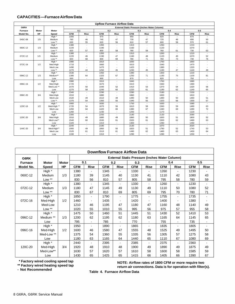
The return air ductwork may be connected to any or all of thefollowing: left side return, right side return, or bottom return.Table 3 shows the airflow data for each furnace model.Where maximum airflow is 1800 CFM or more, twoopenings must be used.
8 G6RA, G6RK Service Manual
Table 4. Furnace Airflow Data
CAPACITIES —Furnace Airflow Data
** Factory wired cooling speed tap** Factory wired heating speed tap- Not Recommended
NOTE: Airflow rates of 1800 CFM or more require tworeturn air connections. Data is for operation with filter(s).
Downflow Furnace Airflow Data
G6RKFurnace Motor Motor
Model No. Speed HP CFM Rise CFM Rise CFM Rise CFM Rise CFM RiseHigh * 1380 - 1345 - 1330 - 1260 - 1230 -
060C-12 Medium 1/3 1180 39 1145 40 1130 41 1110 42 1080 43Low ** 830 56 810 57 805 58 795 58 780 59High * 1380 - 1345 - 1330 - 1260 - 1230 -
072C-12 Medium 1/3 1180 47 1145 49 1130 49 1110 50 1080 52Low ** 830 67 810 69 805 69 795 70 780 71High * 1850 - 1790 - 1775 - 1755 - 1735 -
072C-16 Med-High 1/2 1460 - 1435 - 1420 - 1400 - 1380 -Med-Low 1210 46 1195 47 1180 47 1160 48 1140 49Low ** 1020 55 1010 55 995 56 975 57 955 58High * 1475 50 1460 51 1445 51 1430 52 1410 53
096C-12 Medium ** 1/3 1200 62 1195 62 1180 63 1165 64 1145 65Low 795 - 785 - 770 - 755 - 735 -
High * 1950 - 1890 - 1865 - 1835 - 1805 -096C-16 Med-High 1/2 1600 46 1580 47 1555 48 1525 49 1495 50
Med-Low ** 1375 54 1360 55 1335 56 1305 57 1275 58Low 1180 63 1165 64 1440 65 1110 67 1080 69
High * 2440 - 2395 - 2385 - 2375 - 2360 -120C-20 Med-High 3/4 1920 48 1910 48 1900 49 1890 49 1875 49
Med-Low** 1630 57 1620 57 1610 58 1600 58 1585 59Low 1430 65 1425 65 1415 66 1405 66 1390 67
External Static Pressure (inches Water Column)0.1 0.2 0.3 0.4 0.5
Upflow Furnace Airflow DataG6RA External Static Pressure (Inches Water Column)
Furnace Motor Motor 0.1 0.2 0.3 0.4 0.5
Model No. HP Speed CFM Rise CFM Rise CFM Rise CFM Rise CFM RiseHigh * 1000 - 970 - 950 - 920 - 870 -
045C-08 1/5 Medium 760 46 740 47 730 47 720 48 690 50Low ** 630 55 620 56 610 57 600 58 570 61High * 1380 - 1350 - 1310 - 1260 - 1210 -
060C-12 1/3 Medium 1220 - 1190 - 1160 - 1120 - 1070 -Low ** 820 57 800 58 780 59 760 61 730 63High * 1380 - 1350 - 1310 - 1260 - 1210 -
072C-12 1/3 Medium 1220 46 1190 47 1160 48 1120 49 1070 52Low ** 820 68 800 69 780 71 760 73 730 76High * 1980 - 1910 - 1830 - 1760 - 1660 -
072C-16 1/2 Med-High 1710 - 1660 - 1610 - 1540 - 1470 -Med-Low 1490 - 1470 - 1420 - 1380 - 1320 -
Low ** 1270 44 1250 45 1230 45 1190 47 1140 49High * 1530 - 1450 - 1390 - 1300 - 1220 -
096C-12 1/3 Medium** 1380 64 1320 67 1250 71 1190 75 1100 81Low 930 - 900 - 870 - 820 - 750 -
High * 1980 - 1910 - 1840 - 1760 - 1680 -096C-16 1/2 Med-High 1720 - 1670 - 1610 - 1560 - 1480 -
Med-Low ** 1470 50 1440 52 1410 53 1370 54 1320 56Low 1270 58 1240 60 1220 61 1190 62 1140 65
High * 2340 - 2290 - 2280 - 2180 - 2150 -096C-20 3/4 Med-High 1910 - 1880 - 1860 - 1830 - 1810 -
Med-Low 1520 49 1510 49 1490 50 1480 50 1460 51Low ** 1370 54 1350 55 1340 55 1320 56 1300 57High * 1900 - 1830 - 1750 - 1630 - 1580 -
120C-16 1/2 Med-High ** 1720 54 1670 56 1610 58 1560 59 1480 63Med-Low 1450 64 1420 65 1380 67 1340 69 1280 72
Low 1260 - 1230 - 1200 - 1170 - 1120 -High * 2300 - 2250 - 2190 - 2130 - 2090 -
120C-20 3/4 Med-High 1910 49 1880 49 1860 50 1830 51 1800 52Med-Low** 1540 60 1530 61 1520 61 1500 62 1480 63
Low 1320 - 1310 - 1300 - 1280 - 1260 -High * 2240 - 2190 - 2130 - 1070 - 2020 -
144C-20 3/4 Med-High** 1900 49 1860 50 1820 51 1780 52 1740 53Med-Low 1520 61 1510 61 1490 62 1480 63 1450 64
Low 1330 - 1310 - 1290 - 1280 - 1250 -
G6RA, G6RK Service Manual 9
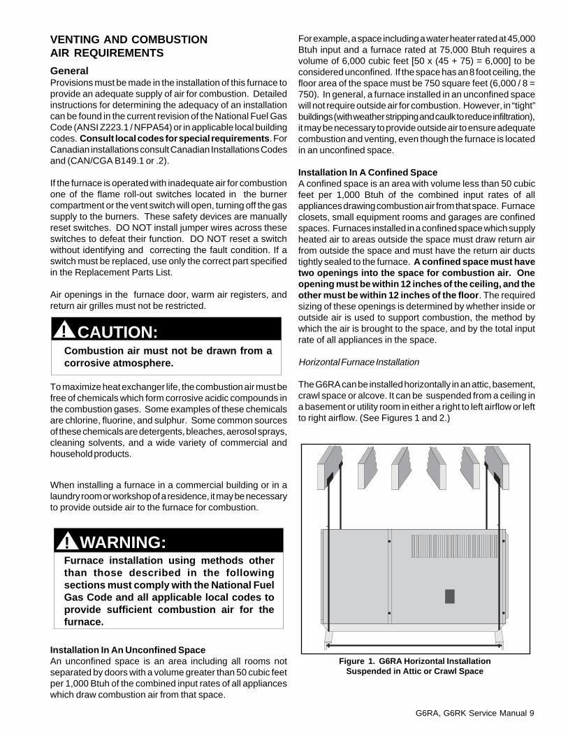
Figure 1. G6RA Horizontal InstallationSuspended in Attic or Crawl Space
Combustion air must not be drawn from acorrosive atmosphere.
CAUTION:!
WARNING:Furnace installation using methods otherthan those described in the followingsections must comply with the National FuelGas Code and all applicable local codes toprovide sufficient combustion air for thefurnace.
!
VENTING AND COMBUSTIONAIR REQUIREMENTS
GeneralProvisions must be made in the installation of this furnace toprovide an adequate supply of air for combustion. Detailedinstructions for determining the adequacy of an installationcan be found in the current revision of the National Fuel GasCode (ANSI Z223.1 / NFPA54) or in applicable local buildingcodes. Consult local codes for special requirements . ForCanadian installations consult Canadian Installations Codesand (CAN/CGA B149.1 or .2).
If the furnace is operated with inadequate air for combustionone of the flame roll-out switches located in the burnercompartment or the vent switch will open, turning off the gassupply to the burners. These safety devices are manuallyreset switches. DO NOT install jumper wires across theseswitches to defeat their function. DO NOT reset a switchwithout identifying and correcting the fault condition. If aswitch must be replaced, use only the correct part specifiedin the Replacement Parts List.
Air openings in the furnace door, warm air registers, andreturn air grilles must not be restricted.
To maximize heat exchanger life, the combustion air must befree of chemicals which form corrosive acidic compounds inthe combustion gases. Some examples of these chemicalsare chlorine, fluorine, and sulphur. Some common sourcesof these chemicals are detergents, bleaches, aerosol sprays,cleaning solvents, and a wide variety of commercial andhousehold products.
When installing a furnace in a commercial building or in alaundry room or workshop of a residence, it may be necessaryto provide outside air to the furnace for combustion.
Installation In An Unconfined SpaceAn unconfined space is an area including all rooms notseparated by doors with a volume greater than 50 cubic feetper 1,000 Btuh of the combined input rates of all applianceswhich draw combustion air from that space.
For example, a space including a water heater rated at 45,000Btuh input and a furnace rated at 75,000 Btuh requires avolume of 6,000 cubic feet [50 x (45 + 75) = 6,000] to beconsidered unconfined. If the space has an 8 foot ceiling, thefloor area of the space must be 750 square feet (6,000 / 8 =750). In general, a furnace installed in an unconfined spacewill not require outside air for combustion. However, in “tight”buildings (with weather stripping and caulk to reduce infiltration),it may be necessary to provide outside air to ensure adequatecombustion and venting, even though the furnace is locatedin an unconfined space.
Installation In A Confined SpaceA confined space is an area with volume less than 50 cubicfeet per 1,000 Btuh of the combined input rates of allappliances drawing combustion air from that space. Furnaceclosets, small equipment rooms and garages are confinedspaces. Furnaces installed in a confined space which supplyheated air to areas outside the space must draw return airfrom outside the space and must have the return air ductstightly sealed to the furnace. A confined space must havetwo openings into the space for combustion air. Oneopening must be within 12 inches of the ceiling, and theother must be within 12 inches of the floor . The requiredsizing of these openings is determined by whether inside oroutside air is used to support combustion, the method bywhich the air is brought to the space, and by the total inputrate of all appliances in the space.
Horizontal Furnace Installation
The G6RA can be installed horizontally in an attic, basement,crawl space or alcove. It can be suspended from a ceiling ina basement or utility room in either a right to left airflow or leftto right airflow. (See Figures 1 and 2.)

10 G6RA, G6RK Service Manual
Figure 2. G6RA Horizontal installation on a Platform
Figure 3. Equipment in a Confined Space with allCombustion Air Drawn from the Inside
Figure 4. Equipment in a Confined Space with allCombustion Air Drawn from the Outside
through Vertical Ducts
If the furnace is to be suspended from the ceiling, it will benecessary to use steel straps around each end of thefurnace. These straps should be attached to the furnace withsheet metal screws and to the rafters with bolts. The furnacecould also be suspended by an angle iron frame bolted to therafters. (See Figure 1.)
Thirty six (36) inches between the front of the furnace andadjacent construction or other appliances should be maintainedfor service clearance.
Keep all insulating materials away from the louvered door.Insulating materials may be combustible.
The G6RA may be installed directly on combustible woodflooring or supports, if type "B-1" vent pipe is used (SeeFigure 2). It is recommended for further reduction of firehazard that cement board or sheet metal be placed betweenthe G6RA and the combustible floor and extend 12 inchesbeyond the front of the louvered door.
Air From Inside (See Figure 3) If combustion air is taken from the heated space, the twoopenings must each have a free area of at least one squareinch per 1,000 Btuh of total input of all appliances in theconfined space, but not less than 100 square inches of freearea. For example, if the combined input rate of all appliancesis less than or equal to 100,000 Btuh, each opening musthave a free area of at least 100 square inches. If thecombined input rate of all appliances is 120,000 Btuh, eachopening must have a free area of at least 120 square inches.
Total InputRating (Btu/hr)
40,000 60,000 80,000100,000120,000140,000160,000
Round DuctDiameter
12"12"12"12"13"14"15"
MinimumFree Area
(Each Opening)100 sq. in.100 sq. in.100 sq. in.100 sq. in.120 sq. in.140 sq. in.160 sq. in.
Furnace
Openings toadjacent space.Each opening mustbe at least 100 sq. in.or 1 sq. in. per 1000Btuh of total inputrating, whichever isgreater. See minimumarea per table.
12" Max.
12" Max.
Water Heater
Vent orChimney
Total InputRating (Btu/hr)
40,000 60,000 80,000100,000120,000140,000160,000
MinimumFree Area
(Each Opening)
10 sq. in.15 sq. in.20 sq. in.25 sq. in.30 sq. in.35 sq. in.40 sq. in.
Round DuctDiameter
4"5"5"6"6"7"8"
Inlet Air Duct mustbe at least 1 sq. in.per 4,000 Btuh oftotal input rating.
Inlet and Outlet Ductsmust extend aboveattic insulation.
Outlet Air Duct mustbe at least 1 sq. in.per 4,000 Btuh oftotal input rating.
Ventilation Louvers ateach end of attic
AtticInsulation
12" Max
a. All Combustion Air from Ventilated Attic.
Furnace
Water Heater
Vent orChimney
For venting follow the guidelines specified under the ventingsection.
Gas Inlet
Electrical Supply
Connection
Coil Plenum
Type “B” Vent
CombustiblePlatform
Louver Door
Note: Line Contact is Permissible
Furnaces installed with combustion air drawnfrom a heated space which includes exhaustfans, fireplaces, or other devices that mayproduce a negative pressure should beconsidered confined space installations.
WARNING:!
Outdoor Air Using Vertical Ducts(See Figure 4)If combustion air is taken from outdoors through verticalducts, the openings and ducts must have a minimum freearea of one square inch per 4,000 Btuh of total applianceinput. In installations drawing combustion air from a ventilatedattic, both air ducts must extend above the attic insulation.
G6RA, G6RK Service Manual 11
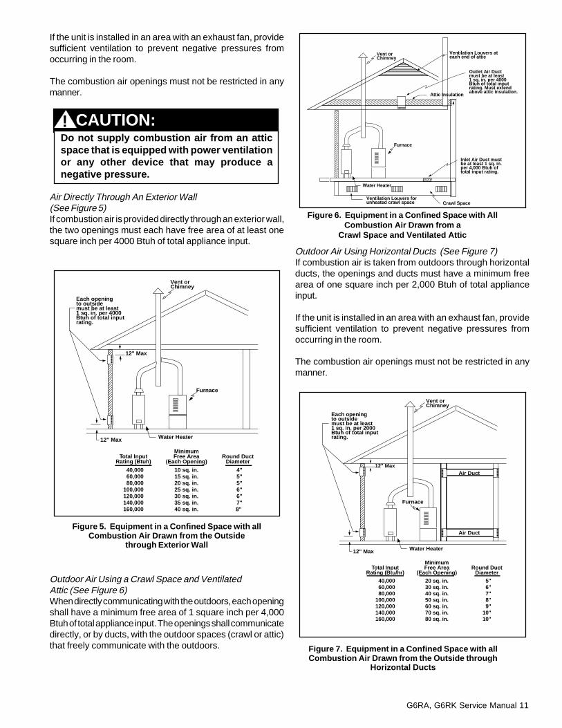
Figure 5. Equipment in a Confined Space with allCombustion Air Drawn from the Outside
through Exterior Wall
Figure 6. Equipment in a Confined Space with AllCombustion Air Drawn from a
Crawl Space and Ventilated Attic
Figure 7. Equipment in a Confined Space with allCombustion Air Drawn from the Outside through
Horizontal Ducts
If the unit is installed in an area with an exhaust fan, providesufficient ventilation to prevent negative pressures fromoccurring in the room.
The combustion air openings must not be restricted in anymanner.
Air Directly Through An Exterior Wall(See Figure 5)If combustion air is provided directly through an exterior wall,the two openings must each have free area of at least onesquare inch per 4000 Btuh of total appliance input.
Outdoor Air Using a Crawl Space and VentilatedAttic (See Figure 6)When directly communicating with the outdoors, each openingshall have a minimum free area of 1 square inch per 4,000Btuh of total appliance input. The openings shall communicatedirectly, or by ducts, with the outdoor spaces (crawl or attic)that freely communicate with the outdoors.
Outdoor Air Using Horizontal Ducts (See Figure 7)If combustion air is taken from outdoors through horizontalducts, the openings and ducts must have a minimum freearea of one square inch per 2,000 Btuh of total applianceinput.
If the unit is installed in an area with an exhaust fan, providesufficient ventilation to prevent negative pressures fromoccurring in the room.
The combustion air openings must not be restricted in anymanner.
Outlet Air Ductmust be at least1 sq. in. per 4000 Btuh of total inputrating. Must extend above attic insulation.
Ventilation Louvers ateach end of attic
Attic Insulation
Ventilation Louvers forunheated crawl space Crawl Space
Inlet Air Duct mustbe at least 1 sq. in.per 4,000 Btuh oftotal input rating.
Furnace
Water Heater
Vent orChimney
Each openingto outsidemust be at least1 sq. in. per 2000 Btuh of total inputrating.
12" Max
12" Max
Total InputRating (Btu/hr)
40,000 60,000 80,000100,000120,000140,000160,000
MinimumFree Area
(Each Opening)
20 sq. in.30 sq. in.40 sq. in.50 sq. in.60 sq. in.70 sq. in.80 sq. in.
Round DuctDiameter
5" 6" 7" 8" 9"10"10"
---------
---------
Furnace
Air Duct
Air Duct
Water Heater
Vent orChimney
---------
---------
---------
---------
Do not supply combustion air from an atticspace that is equipped with power ventilationor any other device that may produce anegative pressure.
CAUTION:!
Each openingto outsidemust be at least1 sq. in. per 4000 Btuh of total inputrating.
12" Max
12" Max
Total InputRating (Btuh)
40,000 60,000 80,000100,000120,000140,000160,000
MinimumFree Area
(Each Opening)
10 sq. in.15 sq. in.20 sq. in.25 sq. in.30 sq. in.35 sq. in.40 sq. in.
Round DuctDiameter
4" 5" 5" 6" 6" 7" 8"
---------
---------
Furnace
Water Heater
Vent orChimney

12 G6RA, G6RK Service Manual
VENTING REQUIREMENTS
GeneralThis furnace must be vented in compliance with, the currentrevision of the National Fuel Gas Code (ANSI-Z223.1/NFPA54),with the instructions provided below, and with the CategoryI Venting Tables provided with the furnace.
In Canada, venting shall conform to the requirements of thecurrent (CAN/CGA B149.1 or .2) installation codes. Consultlocal codes for special requirements.
This furnace must never be vented to a chimney flueservicing a fireplace or other appliance designed to burn solidfuel. If the furnace vent is to be connected to a chimneyserving a fireplace, the fireplace must be sealed off from thechimney.
The furnace vent, if metal, may be insulated if local codesallow. Any part of the vent system, metal vent only, notexposed to weather, but which are exposed to ambienttemperatures below 35° F must be insulated to preventcondensation. All vent insulation shall be foil backedfiberglass of one inch minimum thickness.
Category I - Common VentingWhen an existing furnace is removed from a venting systemserving other appliances, the venting system is likely to betoo large to properly vent the remaining appliances.
The following steps shall be followed with each individualappliance connected to the venting system placed in operation,while all other appliances connected to the venting systemare not in operation:
(a) Seal any unused openings in the venting system.
(b) Inspect the venting system for proper size and horizontalpitch, as required in the National Fuel Gas Code, (ANSIZ223.1) or the (CAN/CGA B149 ) Installation Codes andthese instructions. Determine that there is no blockage orrestriction, leakage, corrosion or other deficiencies whichcould cause an unsafe condition.
(c) In so far as is practical, close all building doors andwindows and all doors between the space in which theappliance(s) connected to the venting system are locatedand other spaces of the building. Turn on clothes dryers andany appliance not connected to the venting system. Turn onany exhaust fans, such as range hoods and bathroomexhausts, so they shall operate at maximum speed. Do notoperate a summer exhaust fan. Close fireplace dampers.
(d) Follow the lighting instructions. Place the appliance beinginspected in operation. Adjust thermostat so appliance shalloperate continuously.
(e) Test for draft hood equipped appliance spillage at the drafthood relief opening after 5 minutes of main burner operation.Use the flame of a match or candle.
(f) After it has been determined that each appliance connectedto the venting system properly vents when tested as outlinedabove, return doors, windows, exhaust fans, fireplace dampersand any other gas burning appliance to their previous conditionsof use.
(g) If improper venting is observed during any of the abovetests, the venting system must be corrected.
(Categorie I) — Proceder comme suit pour chaque appareilraccorde a la tuyauterie d’evacuation et en etat normal defonctionnement; tous les autres appareils raccordes a lameme tuyauterie d’evacuation doivent etre mis hors service:
(a)sceller toute ouverture non utilisee de la tuyauteried’evacuation.
(b)s’assurer que la tuyauterie d’evacuation presente desdimensions et une pente horizontale conformes a la normeANSI Z223.1, intitulee National Fuel Gas Code ou aux codesd’installation CAN/CGA-B149, ainsi qu’aux presentesinstructions. S’assurer que la tuyauterie n’est pas bloquee,restreinte, corrodee, qu’elle ne fuit pas et qu’elle ne presenteaucun autre defaut potentiellement dangereux.
(c)dans la mesure du possible, fermer toutes les portes etfenetres du batiment, et toutes les portes entre la piece ou setrouve l’appareil raccorde a la tuyauterie d’evacuation et lesautres pieces du batiment. Mettre en service les secheuseset tout autre appareil qui n’est pas raccorde a la tuyauteried’evacuation. Faire fonctionner a regime maximal toutventilateur d’evacuation, tel que les hottes de cuisiniere etles ventilateurs de salles de bains. Ne pas mettre en serviceles ventilateurs d’ete. Fermer les registres des foyers.
(d)respecter les instructions d’allumage. Mettre en servicel’appareil a l’essai. Regler le thermostat de maniere a ce quel’appareil fonctionne sans interruption.
(e)s’assurer qu’un appareil muni d’un coupe-tirage ne presenteaucune fuite a l’ouverture du coupe-tirage apres que le bruleurprincipal ait fonctionne pendant cinq minutes. Employer laflamme d’une allumette ou d’une chandelle.
(f)apres avoir determine que tous les appareils raccordes ala tuyauterie d’evacuation evacuent correctement tel queprescrit ci-dessus, rouvrir les portes at les fenetres etremettre les ventilateurs d’evacuation, les registres de foyerset tout autre appareil fonctionnant au gaz a leur etat defonctionnement initial.
(g)si un appareil n’evacue pas correctement a la suite de l’undes essais ci dessus, corriger la tuyauterie d’evacuation.

G6RA, G6RK Service Manual 13
CoverPlate
Nut
Covered Vent Collar Hole
Looking Down atVent Opening
Figure 8. G6RA Bleed Tube Installation
Figure 9. G6RA Vent Collar Detail
The venting system should be designed to have the minimumnumber of elbows or turns. All horizontal runs shall besloped upwards from the furnace at 1/4 inch per running footof vent. Supports for the vent pipe must be installed aminimum of every five feet along the vent run to ensure nodisplacement after installation.
Under no circumstances shall any portion of the vent systemextend into or pass through any return air duct, supply airduct, or plenum.
If the furnace is operated with blocked or restricted venting,the blocked vent switch located in the vent plate will open,turning off the gas supply to the burners. The blocked ventswitch is a manually reset device. DO NOT install a jumperwire across this switch to defeat its function. DO NOT resetthe switch without identifying and correcting the fault conditionwhich caused the switch to trip. If this switch must bereplaced, use only the part specified in the ReplacementParts List.
Category III - Horizontal Venting
NOTE: The reduced NOx models (eighth character N) are notapproved as a Category III (Categorie III) furnace for use withhorizontal venting.
The furnaces are approved for use with 3" single wall AL29-4C stainless steel vent pipe in horizontal vent applications.This pipe is available from the following manufacturers:Z-FLEX Inc. - vent brand name (Z-VENT)Heat-fab Inc. - vent brand name (Saf-T Vent)Flex-L International - vent brand name (Star-34 Vent)
This vent pipe must be used for the entire length of the ventrun. The installation must be in accordance with all instructionssupplied by the vent manufacturer for use on Category IIIappliances. When venting horizontally this is a Category IIIfurnace, the vent pressure is positive, and the ventingsystem must be sealed.
For horizontal venting installations in both the United Statesand Canada the transition assembly must be modified, thebleed tube must be added to the pressure switch tube, andthe vent switch must be by-passed. The bleed tube is foundin an envelope, attached to the furnace literature.
Horizontal Venting For G6RA Models:
NOTE: An optional horizontal vent kit will be required. SeeVent Kit Bleed Tube Chart on Page 40.
1. Remove the rubber tubing from the pressure switchsensor tube and the collector pan sensor tube. Cut 1/2inch from one end of the rubber sensor tube, fold in halfand cut along the bend line. Discard the 1/2 inch longpiece and place the other two pieces on both ends of thebleed tube, do not cover the hole in the bleed tube. Placethe assembly back on the pressure switch sensor tubeand the collector pan sensor tube.(See Figure 8.)
2. Remove the nut and restrictor plate from the vent collarassembly and discard the restrictor plate. Remove thecover plate from the envelope attached to the furnaceliterature, and fit the clearance hole over the weld stud.The cover plate must cover the hole(s) on the vent collarassembly. Tighten the nut securely while holding thecover plate in position. (See Figure 9.)
3. Bypass the vent switch by removing both wires fromthe vent switch and attaching them to the wire nut.(See Figure 10.)
Horizontal Venting For G6RK Models:
NOTE: An optional horizontal vent kit will be required. SeeVent Kit Bleed Tube Chart on Page 40.
CollectorPan
PressureSwitch
CutSensorTubes Bleed Tube
Bleed TubeOrifice
WARNING:Upon completion of the furnace installation,carefully inspect the entire flue system bothinside and outside the furnace to assure it isproperly sealed. Leaks in the flue system canresult in serious personal injury or death dueto exposure of flue products, includingcarbon monoxide.
!
14 G6RA, G6RK Service Manual
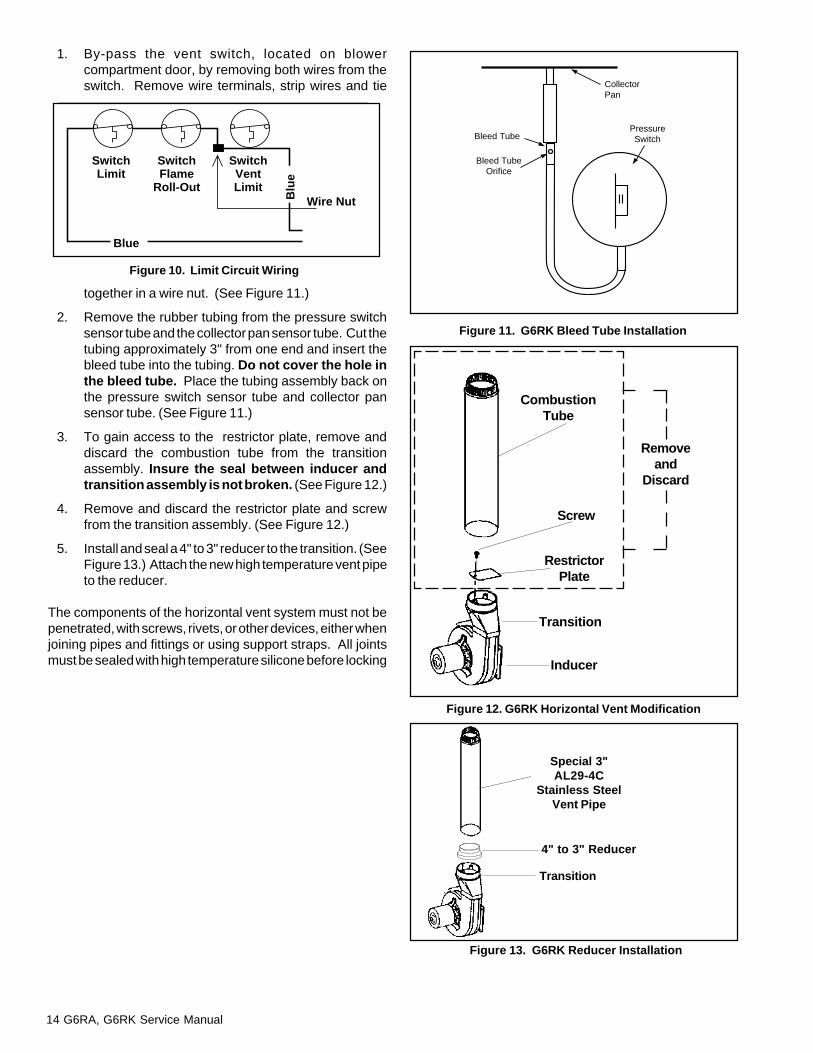
Figure 10. Limit Circuit Wiring
Bleed Tube
Bleed TubeOrifice
CollectorPan
PressureSwitch
Transition
Inducer
Removeand
Discard
Figure 13. G6RK Reducer Installation
Figure 12. G6RK Horizontal Vent Modification
Figure 11. G6RK Bleed Tube Installation
CombustionTube
Screw
RestrictorPlate
Transition
4" to 3" Reducer
Special 3"AL29-4C
Stainless SteelVent Pipe
Wire Nut
SwitchLimit
SwitchFlame
Roll-Out
SwitchVentLimit
Blue
Blu
e
1. By-pass the vent switch, located on blowercompartment door, by removing both wires from theswitch. Remove wire terminals, strip wires and tie
together in a wire nut. (See Figure 11.)
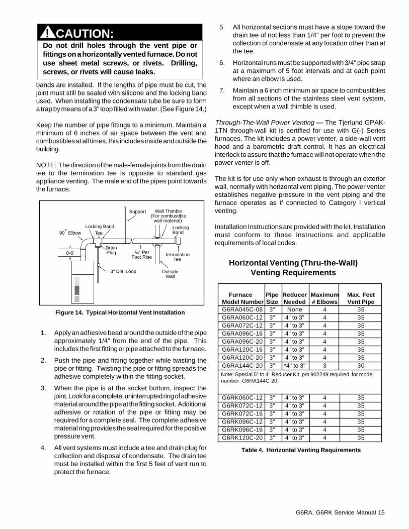
2. Remove the rubber tubing from the pressure switchsensor tube and the collector pan sensor tube. Cut thetubing approximately 3" from one end and insert thebleed tube into the tubing. Do not cover the hole inthe bleed tube. Place the tubing assembly back onthe pressure switch sensor tube and collector pansensor tube. (See Figure 11.)
3. To gain access to the restrictor plate, remove anddiscard the combustion tube from the transitionassembly. Insure the seal between inducer andtransition assembly is not broken. (See Figure 12.)
4. Remove and discard the restrictor plate and screwfrom the transition assembly. (See Figure 12.)
5. Install and seal a 4" to 3" reducer to the transition. (SeeFigure 13.) Attach the new high temperature vent pipeto the reducer.
The components of the horizontal vent system must not bepenetrated, with screws, rivets, or other devices, either whenjoining pipes and fittings or using support straps. All jointsmust be sealed with high temperature silicone before locking
G6RA, G6RK Service Manual 15
CAUTION:Do not drill holes through the vent pipe orfittings on a horizontally vented furnace. Do notuse sheet metal screws, or rivets. Drilling,screws, or rivets will cause leaks.
Figure 14. Typical Horizontal Vent Installation
Furnace Pipe Reducer Maximum Max. FeetModel Number Size Needed # Elbows Vent PipeG6RA045C-08 3" None 4 35G6RA060C-12 3" 4" to 3" 4 35G6RA072C-12 3" 4" to 3" 4 35G6RA096C-16 3" 4" to 3" 4 35G6RA096C-20 3" 4" to 3" 4 35G6RA120C-16 3" 4" to 3" 4 35G6RA120C-20 3" 4" to 3" 4 35G6RA144C-20 3" *4" to 3" 3 30
G6RK060C-12 3" 4" to 3" 4 35G6RK072C-12 3" 4" to 3" 4 35G6RK072C-16 3" 4" to 3" 4 35G6RK096C-12 3" 4" to 3" 4 35G6RK096C-16 3" 4" to 3" 4 35G6RK120C-20 3" 4" to 3" 4 35
Note: Special 5" to 4" Reducer Kit, p/n 902249 required for modelnumber G6RA144C-20.
Table 4. Horizontal Venting Requirements
Horizontal Venting (Thru-the-Wall)Venting Requirements
!
bands are installed. If the lengths of pipe must be cut, thejoint must still be sealed with silicone and the locking bandused. When installing the condensate tube be sure to forma trap by means of a 3" loop filled with water. (See Figure 14.)
Keep the number of pipe fittings to a minimum. Maintain aminimum of 6 inches of air space between the vent andcombustibles at all times, this includes inside and outside thebuilding.
NOTE: The direction of the male-female joints from the draintee to the termination tee is opposite to standard gasappliance venting. The male end of the pipes point towardsthe furnace.
1. Apply an adhesive bead around the outside of the pipeapproximately 1/4" from the end of the pipe. Thisincludes the first fitting or pipe attached to the furnace.
2. Push the pipe and fitting together while twisting thepipe or fitting. Twisting the pipe or fitting spreads theadhesive completely within the fitting socket.
3. When the pipe is at the socket bottom, inspect thejoint. Look for a complete, uninterrupted ring of adhesivematerial around the pipe at the fitting socket. Additionaladhesive or rotation of the pipe or fitting may berequired for a complete seal. The complete adhesivematerial ring provides the seal required for the positivepressure vent.
4. All vent systems must include a tee and drain plug forcollection and disposal of condensate. The drain teemust be installed within the first 5 feet of vent run toprotect the furnace.
5. All horizontal sections must have a slope toward thedrain tee of not less than 1/4" per foot to prevent thecollection of condensate at any location other than atthe tee.
6. Horizontal runs must be supported with 3/4" pipe strapat a maximum of 5 foot intervals and at each pointwhere an elbow is used.
7. Maintain a 6 inch minimum air space to combustiblesfrom all sections of the stainless steel vent system,except when a wall thimble is used.
Through-The-Wall Power Venting — The Tjerlund GPAK-1TN through-wall kit is certified for use with G(-) Seriesfurnaces. The kit includes a power venter, a side-wall venthood and a barometric draft control. It has an electricalinterlock to assure that the furnace will not operate when thepower venter is off.
The kit is for use only when exhaust is through an exteriorwall, normally with horizontal vent piping. The power venterestablishes negative pressure in the vent piping and thefurnace operates as if connected to Category I verticalventing.
Installation Instructions are provided with the kit. Installationmust conform to those instructions and applicablerequirements of local codes.
90˚ Elbow
3" Dia. Loop OutsideWall
Wall Thimble(For combustible
wall material)
TerminationTee
Support
Tee
0-6' DrainPlug 1/4" Per
Foot Rise
Locking Band LockingBand

16 G6RA, G6RK Service Manual
4 ft. min4 ft. min
12 in. min
Mechanicaldraft vent terminal
Mechanicaldraft vent terminal
Forced Air Inlet
Grade
Less than 10 ft.
3 ft. min.
Flexible Vent Systems
WARNING:The entire vent system must be sealed witha high temperature sealant which willwithstand temperatures of 450°F.Recommended sealants: Dow CorningSealant 736 RTV; GE 106 RTV; High TechInd., High TEMP RED.
!
Location of Outdoor Terminations
Horizontal Installation
The vent termination tee must be installed with thefollowing minimum clearances. (See Figure 15.)
Figure 16. Alternate Horizontal Vent Installation
1. The termination tee must be 12 inches above snowlevel or grade level which ever is higher. See Figure 16for alternate method to achieve 12" above snow level.
2. The minimum distance from any door, (openable)window, or gravity air inlet is 4 ft. below, 4 ft. horizontally,or 1 ft. above.
3. The vent termination shall be a minimum of 3 ft. aboveany forced air inlet within 10 ft. (See Figure 15.)
4. Recommended minimum distance from an inside cornerformed by two exterior walls is 6 ft., but is not required.
5. The minimum distance from gas or electric meter(s) is4 ft.
6. Avoid areas where condensate drainage may causeproblems such as above planters, patios, or adjacentto windows where the steam from the flue gasesmay cause fogging. Do not terminate above anypublic walkway.
7. Select the point of wall penetration where the minimum1/4 inch per foot of upward slope can be maintained.
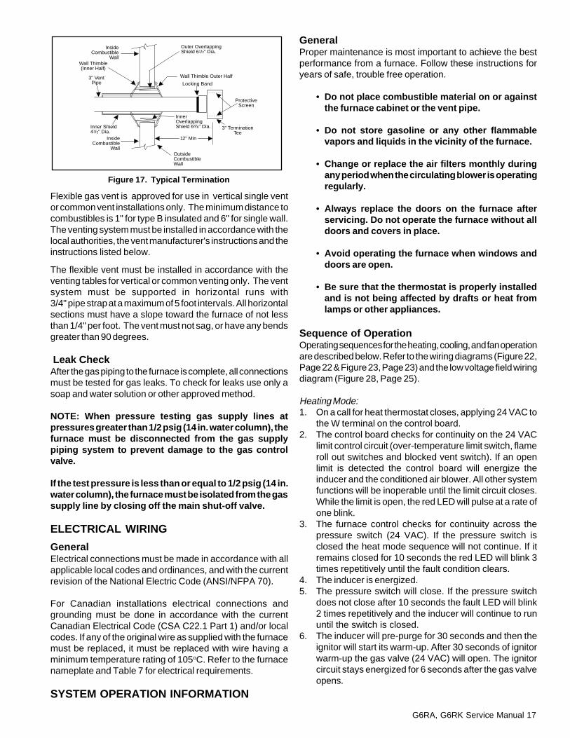
8. When penetrating a noncombustible wall, the holethrough the wall must be large enough to maintain thepitch, pipe clearance for passage, and provide forproper sealing. Penetrating a combustible wallrequires the use of a wall thimble. (See Figure 22.) A6-1/2 inch square framed opening is required to insertthe thimble halves. The thimble is adjustable tovarying wall thickness and is held in place byapplying sealant to the male sleeve before assembly.Also run a bead of sealant around the outer wallthimble.
9. The vent pipe must extend 1-1/4 inches through theouter thimble half for a combustible wall. Be sure tocheck this carefully before cutting the vent pipe.
10. Attach a 3 inch coupling to the end of the pipe thatextends through the wall or thimble. This preventsthe vent pipe from being pushed inward.
11. Cut an 8 inch minimum piece of vent pipe andconnect the coupling to the termination tee. Theinside of the tee must be a minimum of 12 inchesfrom the outside of the wall. (See Figure 17.)
Figure 15. Vent Termination Clearances
Use Wall Thimble atVent Points
Support
Ground Level
Termination Tee
G6RA, G6RK Service Manual 17
Wall Thimble(Inner Half)
Inner Shield41/2" Dia.
Wall Thimble Outer Half
Outer OverlappingShield 61/2" Dia.
3" TerminationTee
ProtectiveScreen
InsideCombustible
Wall
InsideCombustible
Wall
3" VentPipe
OutsideCombustibleWall
Inner OverlappingShield 63/8" Dia.
Locking Band
12" Min
Figure 17. Typical Termination
Flexible gas vent is approved for use in vertical single ventor common vent installations only. The minimum distance tocombustibles is 1" for type B insulated and 6" for single wall.The venting system must be installed in accordance with thelocal authorities, the vent manufacturer's instructions and theinstructions listed below.
The flexible vent must be installed in accordance with theventing tables for vertical or common venting only. The ventsystem must be supported in horizontal runs with3/4" pipe strap at a maximum of 5 foot intervals. All horizontalsections must have a slope toward the furnace of not lessthan 1/4" per foot. The vent must not sag, or have any bendsgreater than 90 degrees.
Leak CheckAfter the gas piping to the furnace is complete, all connectionsmust be tested for gas leaks. To check for leaks use only asoap and water solution or other approved method.
NOTE: When pressure testing gas supply lines atpressures greater than 1/2 psig (14 in. water column), thefurnace must be disconnected from the gas supplypiping system to prevent damage to the gas controlvalve.
If the test pressure is less than or equal to 1/2 psig (14 in.water column), the furnace must be isolated from the gassupply line by closing off the main shut-off valve.
ELECTRICAL WIRING
GeneralElectrical connections must be made in accordance with allapplicable local codes and ordinances, and with the currentrevision of the National Electric Code (ANSI/NFPA 70).
For Canadian installations electrical connections andgrounding must be done in accordance with the currentCanadian Electrical Code (CSA C22.1 Part 1) and/or localcodes. If any of the original wire as supplied with the furnacemust be replaced, it must be replaced with wire having aminimum temperature rating of 105oC. Refer to the furnacenameplate and Table 7 for electrical requirements.
SYSTEM OPERATION INFORMATION
GeneralProper maintenance is most important to achieve the bestperformance from a furnace. Follow these instructions foryears of safe, trouble free operation.
� Do not place combustible material on or againstthe furnace cabinet or the vent pipe.
� Do not store gasoline or any other flammablevapors and liquids in the vicinity of the furnace.
� Change or replace the air filters monthly duringany period when the circulating blower is operatingregularly.
� Always replace the doors on the furnace afterservicing. Do not operate the furnace without alldoors and covers in place.
� Avoid operating the furnace when windows anddoors are open.
� Be sure that the thermostat is properly installedand is not being affected by drafts or heat fromlamps or other appliances.
Sequence of OperationOperating sequences for the heating, cooling, and fan operationare described below. Refer to the wiring diagrams (Figure 22,Page 22 & Figure 23, Page 23) and the low voltage field wiringdiagram (Figure 28, Page 25).
Heating Mode:1. On a call for heat thermostat closes, applying 24 VAC to
the W terminal on the control board.2. The control board checks for continuity on the 24 VAC
limit control circuit (over-temperature limit switch, flameroll out switches and blocked vent switch). If an openlimit is detected the control board will energize theinducer and the conditioned air blower. All other systemfunctions will be inoperable until the limit circuit closes.While the limit is open, the red LED will pulse at a rate ofone blink.
3. The furnace control checks for continuity across thepressure switch (24 VAC). If the pressure switch isclosed the heat mode sequence will not continue. If itremains closed for 10 seconds the red LED will blink 3times repetitively until the fault condition clears.
4. The inducer is energized.5. The pressure switch will close. If the pressure switch
does not close after 10 seconds the fault LED will blink2 times repetitively and the inducer will continue to rununtil the switch is closed.
6. The inducer will pre-purge for 30 seconds and then theignitor will start its warm-up. After 30 seconds of ignitorwarm-up the gas valve (24 VAC) will open. The ignitorcircuit stays energized for 6 seconds after the gas valveopens.
18 G6RA, G6RK Service Manual
7. The furnace control must prove flame via the flamesensor six seconds after the gas valve opens. If flameis sensed, all burners are on and the ignitor cools off. Ifno flame is sensed, the gas valve closes immediatelyand the inducer continues to run. A second trial forignition (step 6) begins if no flame is sensed. On the fifthtry for ignition, the furnace control is locked out and thered LED will blink 4 times repetitively. The thermostatmust be opened for at least ten seconds to reset thefurnace control after a lock out. Otherwise, the furnacewill attempt another ignition sequence in 1 hour.
8. The furnace control energizes the circulating air bloweron the heating speed 30 seconds after the gas valvecircuit is energized.
9. When the thermostat has been satisfied, gas valve is de-energized.
Fan Mode:1. On a call for fan operation, the thermostat applies 24
VAC to the G terminal on the furnace control board.2. The circulating air blower is energized immediately on
the heating speed.3. If the furnace is operated in the continuous ON position
at the thermostat and is then switched to AUTO, thecirculating blower will operate for a specified delay(factory set at 120 seconds).
Furnace Fails to OperateIf the furnace does not operate check the following:
1. Is the thermostat operating properly?2. Are the blower compartment door(s) in place?3. Is the furnace disconnect closed?4. Has the circuit breaker tripped or the control board fuse
burned open?5. Is the gas turned on?6. Are there any manual reset switches open?7. Is the filter dirty or plugged?8. Is the flame sensor coated? (Remove and clean with
steel wool.)
If the furnace locks out after 5 attempts for ignition, it will tryagain every hour if a call for heat remains. If the inducer andcirculating air blowers are operating, and items 1 through 8have been checked, press the red reset button on the ventsafety switch. (See Figure 19.) If the furnace operates afterdepressing the reset button, contact a qualified servicemanto identify and repair the problem.
If the furnace continues to not operate, depress the red resetbutton on the flame roll out switches. (See Figure 19.) If thefurnace operates after depressing the reset buttons, contacta qualified serviceman to identify and repair the problem.
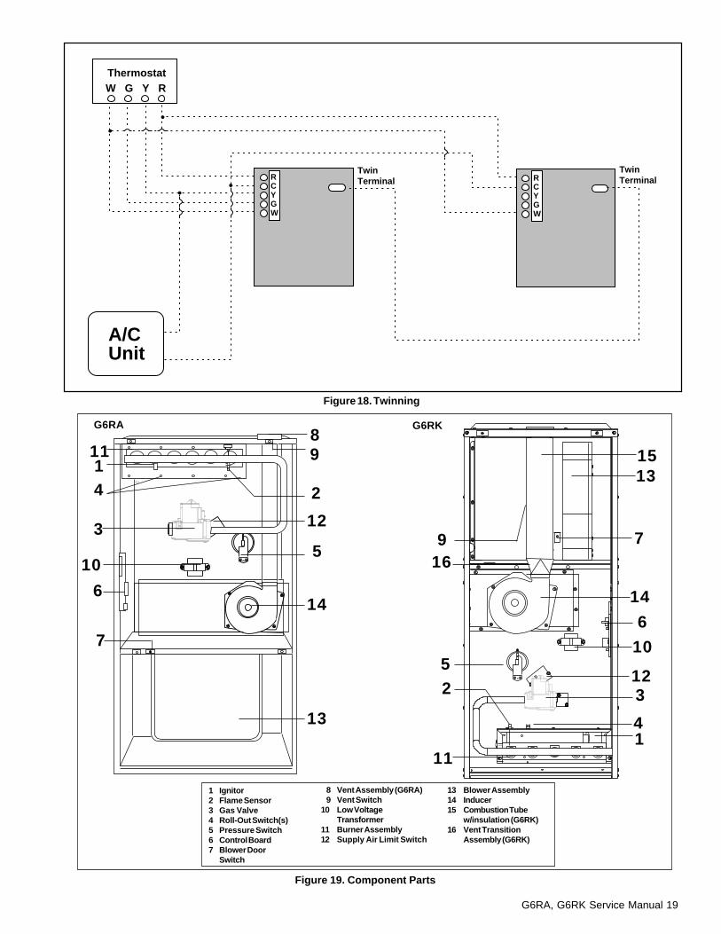
Twinning of Two FurnacesThe control board on a G6 series furnace is capable of beingtwinned to another G6 furnace. The thermostat wires and the3/16 inch quick-connect terminals marked "TWIN" on thefurnace controls must be connected together for twinning.(See Figure 18.)
NOTE: Components are listed in order of sequenceof operation.
10. The inducer is de-energized after a 30 second postpurge.
11. The furnace control keeps the circulating air blowerenergized for 120 second (factory set) or 60, 90, or 180seconds (field adjustable). (See Figure 21.)
12. Abnormal conditions: If a limit opens during operation,the inducer and circulating air blower continue to operate.The gas valve is de-energized immediately. The blowerscontinue to operate until the limit closes. When the limitcloses the induced draft motor will run through postpurge. The circulating air blower continues to operate forthe specified delay (factory set at 120 seconds).
Cooling Mode:1. On a call for cooling the thermostat closes, applying 24
VAC to the G and Y terminals on the furnace control. Thiscloses the compressor contactor.
2. The furnace control energizes the circulating blower (115VAC) on the cooling speed.
3. When the thermostat is satisfied, the G and Y terminalson the control board are de-energized opening thecompressor contactor.
4. The circulating air blower is de-energized after a 90second delay.
CAUTION:!Label all wires prior to disconnection whenservicing controls. Wiring errors can causeimproper and dangerous operation.
Verify proper operation after servicing.
CAUTION:!Do not use matches, lighters, candles or othersources of open flame to check for gas leaks.
G6RA, G6RK Service Manual 19
W G Y RThermostat
A/CUnit
Twin Terminal
Twin TerminalR
CYGW
RCYGW
Figure 18. Twinning
Figure 19. Component Parts
3
41
6
7
1315
10
12
2
5
7
6
3
10
4111
9
52
11
98
12
14
13
16
14
G6RA G6RK
13 Blower Assembly14 Inducer15 Combustion Tube
w/insulation (G6RK)16 Vent Transition
Assembly (G6RK)
1 Ignitor2 Flame Sensor3 Gas Valve4 Roll-Out Switch(s)5 Pressure Switch6 Control Board7 Blower Door
Switch
8 Vent Assembly (G6RA)9 Vent Switch
10 Low VoltageTransformer
11 Burner Assembly12 Supply Air Limit Switch
20 G6RA, G6RK Service Manual
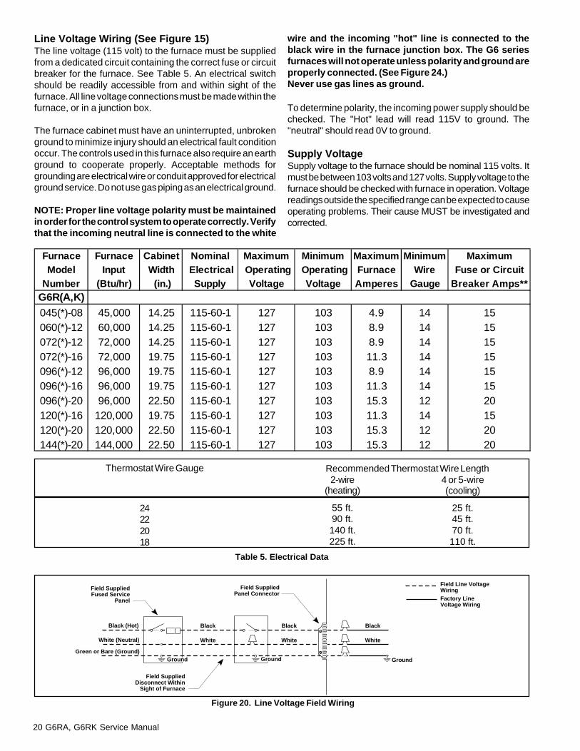
Furnace Furnace Cabinet Nominal Maximum Minimum Maximum Minimum MaximumModel Input Width Electrical Operating Operating Furnace Wire Fuse or Circuit
Number (Btu/hr) (in.) Supply Voltage Voltage Amperes Gauge Breaker Amps**G6R(A,K)045(*)-08 45,000 14.25 115-60-1 127 103 4.9 14 15060(*)-12 60,000 14.25 115-60-1 127 103 8.9 14 15072(*)-12 72,000 14.25 115-60-1 127 103 8.9 14 15072(*)-16 72,000 19.75 115-60-1 127 103 11.3 14 15096(*)-12 96,000 19.75 115-60-1 127 103 8.9 14 15096(*)-16 96,000 19.75 115-60-1 127 103 11.3 14 15096(*)-20 96,000 22.50 115-60-1 127 103 15.3 12 20120(*)-16 120,000 19.75 115-60-1 127 103 11.3 14 15120(*)-20 120,000 22.50 115-60-1 127 103 15.3 12 20144(*)-20 144,000 22.50 115-60-1 127 103 15.3 12 20
Field SuppliedDisconnect Within
Sight of Furnace
Field SuppliedPanel Connector
Field SuppliedFused Service
Panel
Black (Hot)
White (Neutral)
Green or Bare (Ground)
Black
White
Black
White
Black
White
Field Line VoltageWiringFactory LineVoltage Wiring
Ground Ground Ground
Line Voltage Wiring (See Figure 15)The line voltage (115 volt) to the furnace must be suppliedfrom a dedicated circuit containing the correct fuse or circuitbreaker for the furnace. See Table 5. An electrical switchshould be readily accessible from and within sight of thefurnace. All line voltage connections must be made within thefurnace, or in a junction box.
The furnace cabinet must have an uninterrupted, unbrokenground to minimize injury should an electrical fault conditionoccur. The controls used in this furnace also require an earthground to cooperate properly. Acceptable methods forgrounding are electrical wire or conduit approved for electricalground service. Do not use gas piping as an electrical ground.
NOTE: Proper line voltage polarity must be maintainedin order for the control system to operate correctly. Verifythat the incoming neutral line is connected to the white
wire and the incoming "hot" line is connected to theblack wire in the furnace junction box. The G6 seriesfurnaces will not operate unless polarity and ground areproperly connected. (See Figure 24.)Never use gas lines as ground.
To determine polarity, the incoming power supply should bechecked. The "Hot" lead will read 115V to ground. The"neutral" should read 0V to ground.
Supply VoltageSupply voltage to the furnace should be nominal 115 volts. Itmust be between 103 volts and 127 volts. Supply voltage to thefurnace should be checked with furnace in operation. Voltagereadings outside the specified range can be expected to causeoperating problems. Their cause MUST be investigated andcorrected.
Table 5. Electrical Data
Figure 20. Line Voltage Field Wiring
Thermostat Wire Gauge
24222018
2-wire(heating)
55 ft.90 ft.140 ft.225 ft.
Recommended Thermostat Wire Length4 or 5-wire(cooling)
25 ft.45 ft.70 ft.110 ft.
G6RA, G6RK Service Manual 21
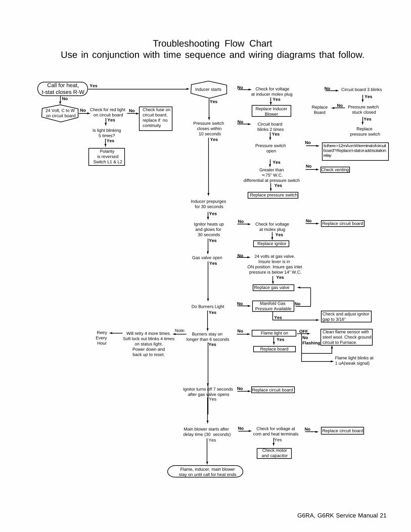
Troubleshooting Flow ChartUse in conjunction with time sequence and wiring diagrams that follow.
Call for heat,t-stat closes R-W
Check for red light on circuit board
24 Volt, C to W on circuit board
Polarity is reversed
Switch L1 & L2
Inducer starts
Check fuse on circuit board, replace if no continuity
Check for voltageat inducer molex plug
Pressure switch stuck closed
ReplaceBoard
Replace pressure switch
Circuit board 3 blinks
Check for voltageat molex plug
Replace InducerBlower
Pressure switch closes within 10 seconds
Circuit board blinks 2 times
Is there >8mA on W terminal of circuit board? Replace t-stat or add isolation relay.
Pressure switch open
Inducer prepurges for 30 seconds
Greater than-1.75" W.C.
differential at pressure switch
Replace pressure switch
Check venting
Ignitor heats upand glows for 30 seconds
Gas valve open
Do Burners Light
Ignitor turns off 7 seconds after gas valve opens
Main blower starts after delay time (30 seconds)
Flame, inducer, main blowerstay on until call for heat ends
Replace ignitor
Replace circuit board
24 volts at gas valve.Insure lever is in
ON position. Insure gas inlet pressure is below 14" W.C.
Replace gas valve
Manifold Gas Pressure Available
Burners stay on longer than 6 seconds
Check and adjust ignitorgap to 3/16"
Will retry 4 more times.Soft lock out blinks 4 times
on status light.Power down andback up to reset.
Replace board
Flame light on
Replace circuit boardCheck for voltage atcom and heat terminals
Replace circuit board
Yes
Yes
Yes
Yes
Yes
YesYes
Yes
Yes
Yes
Yes
Yes
Yes
Yes
Yes
Yes
Yes
Yes
Yes
Yes
Yes
Yes
Check motorand capacitor
Yes
No
No No
No
No
No
No
No No
No
No No
No
NoFlashing
OFF
No
No No
No No
Is light blinking5 times?
Clean flame sensor withsteel wool. Check groundcircuit to Furnace.
Flame light blinks at1 uA(weak signal)
Note: RetryEvery Hour
Is there >12mA on W terminal of circuitboard? Replace t-stat or add isolationrelay

22 G6RA, G6RK Service Manual
Figure 21. UTEC Control Sequence
G6RA, G6RK Service Manual 23
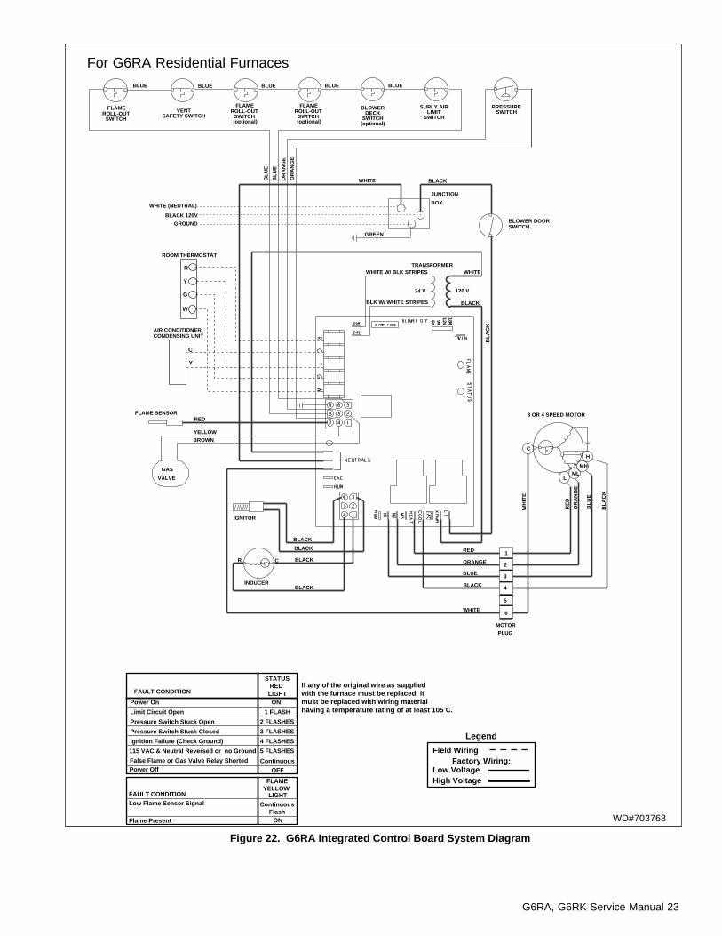
Figure 22. G6RA Integrated Control Board System Diagram
JUNCTION
BOX
IGNITOR
INDUCER
GAS
VALVE
VENTSAFETY SWITCH
SUPLY AIRLIMIT
SWITCH
TRANSFORMER
FLAME SENSOR
C
(optional)
GREEN
BLACKWHITE
BLUE BLUE
24 V 120 VO
RA
NG
E
BLU
E
BLU
E
YELLOWBROWN
RED
BLACK
WHITE
ORANGE
BLUE
BLA
CK
OR
AN
GE
BLACK
RED
AIR CONDITIONERCONDENSING UNIT
BLACK
BLACK
BLOWER DOORSWITCH
R
WHITE
BLACK
WHITE W/ BLK STRIPES
BLK W/ WHITE STRIPES
WHITE (NEUTRAL)
BLACK 120V
GROUND
ROOM THERMOSTAT
3 OR 4 SPEED MOTOR
H
MHML
L
C
WH
ITE
RE
D
OR
AN
GE
BLU
E
BLA
CK
MOTORPLUG
1
2
3
4
5
6
BLACK
BLUE BLUE
FLAMEROLL-OUT
SWITCH
FLAMEROLL-OUT
SWITCH(optional)
FLAMEROLL-OUT
SWITCH
VENTPRESSURE SWITCH
(G6RD Only)
PRESSURESWITCH
BLOWERDECK
SWITCH(optional)
BLUE
R
Y
G
W
C
Y
1801209060
WD#703768
For G6RA Residential Furnaces
Power On
Limit Circuit Open
Pressure Switch Stuck Open
Pressure Switch Stuck Closed
Ignition Failure (Check Ground)
115 VAC & Neutral Reversed or no Ground
False Flame or Gas Valve Relay Shorted
ON
1 FLASH
2 FLASHES
3 FLASHES
4 FLASHES
5 FLASHES
Continuous
STATUSRED LIGHTFAULT CONDITION
Legend
Field WiringFactory Wiring:
Low VoltageHigh Voltage
If any of the original wire as supplied with the furnace must be replaced, it must be replaced with wiring material having a temperature rating of at least 105 C.
Power Off
Low Flame Sensor Signal
Flame Present
ContinuousFlash
OFF
ON
FLAMEYELLOW
LIGHTFAULT CONDITION
24 G6RA, G6RK Service Manual
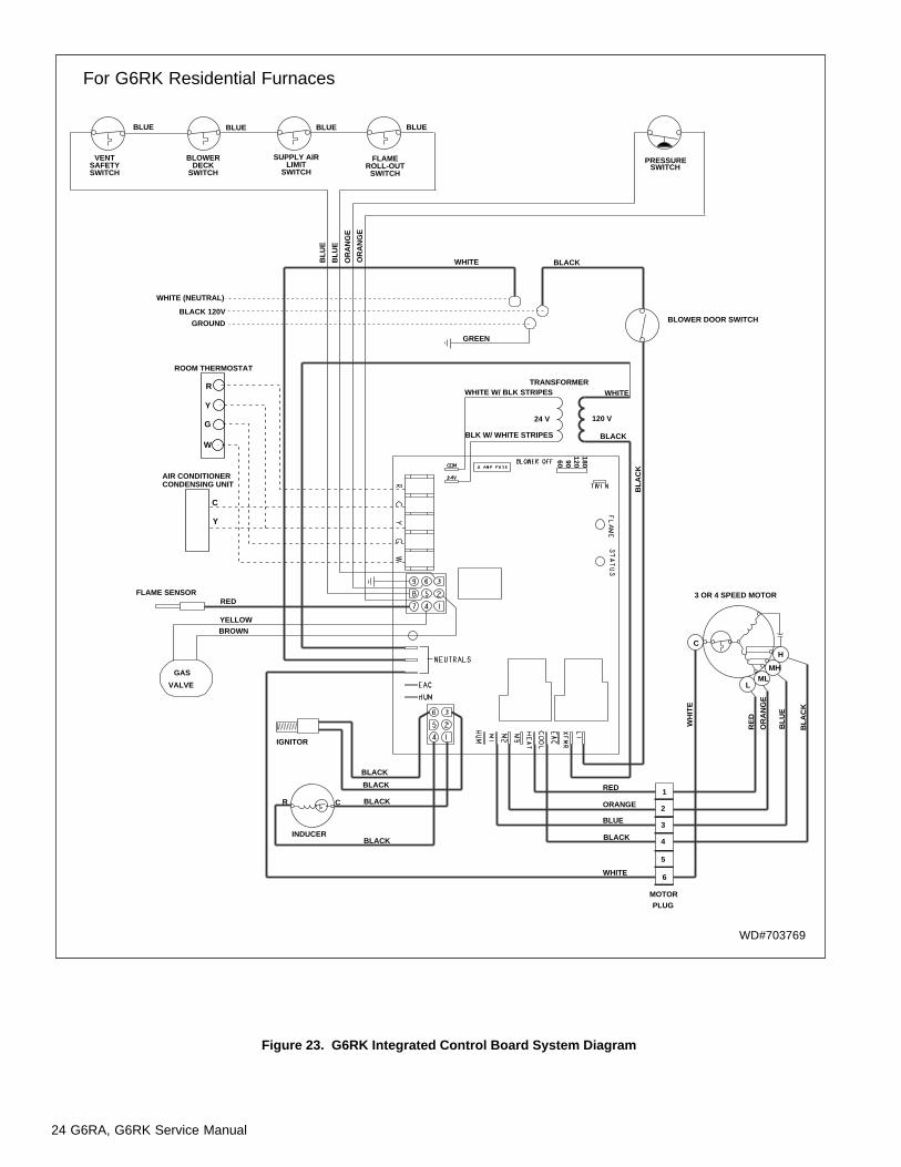
Figure 23. G6RK Integrated Control Board System Diagram
WD#703769
For G6RK Residential Furnaces
IGNITOR
INDUCER
GAS
VALVE
VENTSAFETYSWITCH
BLOWERDECK
SWITCH
SUPPLY AIRLIMIT
SWITCH
FLAMEROLL-OUT
SWITCH
TRANSFORMER
FLAME SENSOR
C
GREEN
BLACKWHITE
BLUE BLUE
24 V 120 V
OR
AN
GE
BLU
E
BLU
E
YELLOWBROWN
RED
BLACK
WHITE
ORANGE
BLUE
BLA
CK
OR
AN
GE
BLACK
RED
AIR CONDITIONERCONDENSING UNIT
BLACK
BLACK
BLOWER DOOR SWITCH
R
WHITE
BLACK
WHITE W/ BLK STRIPES
BLK W/ WHITE STRIPES
WHITE (NEUTRAL)
BLACK 120V
GROUND
ROOM THERMOSTAT
3 OR 4 SPEED MOTOR
H
MHML
L
C
WH
ITE
RE
D
OR
AN
GE
BLU
E
BLA
CK
MOTORPLUG
1
2
3
4
5
6
BLACK
BLUE BLUE
PRESSURESWITCH
R
Y
G
W
C
Y
1801209060
G6RA, G6RK Service Manual 25
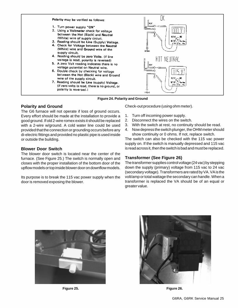
Polarity and GroundThe G6 furnace will not operate if loss of ground occurs.Every effort should be made at the installation to provide agood ground. If old 2-wire romex exists it should be replacedwith a 2-wire w/ground. A cold water line could be usedprovided that the connection or grounding occurs before anydi-electric fittings and provided no plastic pipe is used insideor outside the building.
Blower Door SwitchThe blower door switch is located near the center of thefurnace. (See Figure 25.) The switch is normally open andcloses with the proper installation of the bottom door of theupflow models or top inside blower door on downflow models.
Its purpose is to break the 115 vac power supply when thedoor is removed exposing the blower.
Check-out procedure (using ohm meter).
1. Turn off incoming power supply.2. Disconnect the wires on the switch.3. With the switch at rest, no continuity should be read.4. Now depress the switch plunger, the OHM meter should
show continuity or 0 ohms. If not, replace switch.The switch can also be checked with the 115 vac powersupply on. If the switch is manually depressed and 115 vacis read across it, then the switch is bad and must be replaced.
Transformer (See Figure 26)The transformer supplies control voltage (24 vac) by steppingdown the supply (primary) voltage from 115 vac to 24 vac(secondary voltage). Transformers are rated by VA. VA is thevolt/amp or total wattage the secondary can handle. When atransformer is replaced the VA should be of an equal orgreater value.
Figure 24. Polarity and Ground
Figure 25. Figure 26.
26 G6RA, G6RK Service Manual
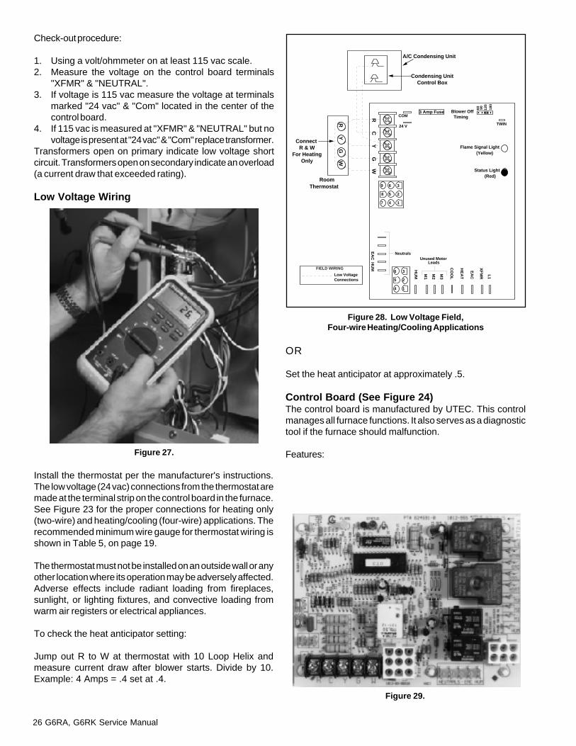
Check-out procedure:
1. Using a volt/ohmmeter on at least 115 vac scale.2. Measure the voltage on the control board terminals
"XFMR" & "NEUTRAL".3. If voltage is 115 vac measure the voltage at terminals
marked "24 vac" & "Com" located in the center of thecontrol board.
4. If 115 vac is measured at "XFMR" & "NEUTRAL" but novoltage is present at "24 vac" & "Com" replace transformer.
Transformers open on primary indicate low voltage shortcircuit. Transformers open on secondary indicate an overload(a current draw that exceeded rating).
Low Voltage Wiring
OR
Set the heat anticipator at approximately .5.
Control Board (See Figure 24)The control board is manufactured by UTEC. This controlmanages all furnace functions. It also serves as a diagnostictool if the furnace should malfunction.
Features:
Install the thermostat per the manufacturer's instructions.The low voltage (24 vac) connections from the thermostat aremade at the terminal strip on the control board in the furnace.See Figure 23 for the proper connections for heating only(two-wire) and heating/cooling (four-wire) applications. Therecommended minimum wire gauge for thermostat wiring isshown in Table 5, on page 19.
The thermostat must not be installed on an outside wall or anyother location where its operation may be adversely affected.Adverse effects include radiant loading from fireplaces,sunlight, or lighting fixtures, and convective loading fromwarm air registers or electrical appliances.
To check the heat anticipator setting:
Jump out R to W at thermostat with 10 Loop Helix andmeasure current draw after blower starts. Divide by 10.Example: 4 Amps = .4 set at .4.
Figure 28. Low Voltage Field,Four-wire Heating/Cooling Applications
R C
Y G
W
A/C Condensing Unit
Condensing UnitControl Box
RoomThermostat
Flame Signal Light (Yellow)
Status Light (Red)
60 90 120
180
Blower Off Timing
TWIN
3 Amp FuseCOM
24 V
HU
M
Neutrals
Low VoltageConnections
4 1
5 2
6 3
7
8
9
4
5
6
1
2
3
EA
C
HU
M M1
M2
M3
CO
OL
HE
AT L1
XF
MR
Unused Motor Leads
EA
C
R Y
G W
Connect R & W
For HeatingOnly
FIELD WIRING
Figure 29.
Figure 27.
G6RA, G6RK Service Manual 27
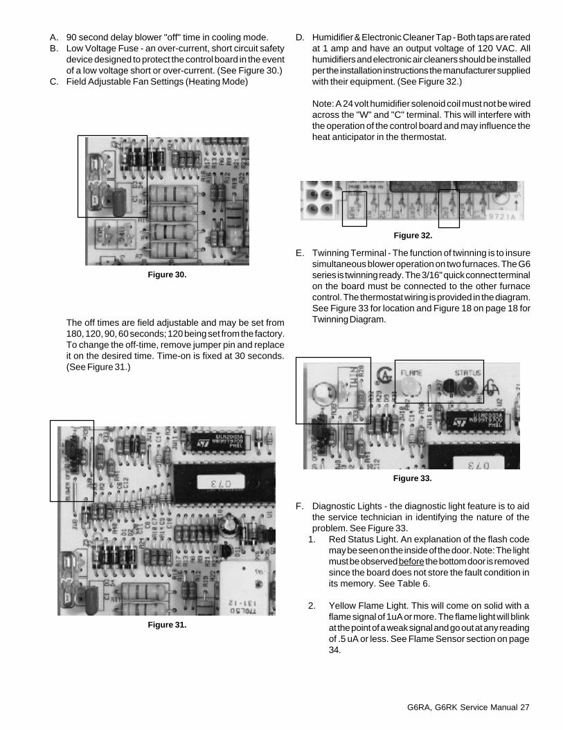
A. 90 second delay blower "off" time in cooling mode.B. Low Voltage Fuse - an over-current, short circuit safety
device designed to protect the control board in the eventof a low voltage short or over-current. (See Figure 30.)
C. Field Adjustable Fan Settings (Heating Mode)
D. Humidifier & Electronic Cleaner Tap - Both taps are ratedat 1 amp and have an output voltage of 120 VAC. Allhumidifiers and electronic air cleaners should be installedper the installation instructions the manufacturer suppliedwith their equipment. (See Figure 32.)
Note: A 24 volt humidifier solenoid coil must not be wiredacross the "W" and "C" terminal. This will interfere withthe operation of the control board and may influence theheat anticipator in the thermostat.
The off times are field adjustable and may be set from180, 120, 90, 60 seconds; 120 being set from the factory.To change the off-time, remove jumper pin and replaceit on the desired time. Time-on is fixed at 30 seconds.(See Figure 31.)
E. Twinning Terminal - The function of twinning is to insuresimultaneous blower operation on two furnaces. The G6series is twinning ready. The 3/16" quick connect terminalon the board must be connected to the other furnacecontrol. The thermostat wiring is provided in the diagram.See Figure 33 for location and Figure 18 on page 18 forTwinning Diagram.
Figure 30.
Figure 32.
Figure 33.
F. Diagnostic Lights - the diagnostic light feature is to aidthe service technician in identifying the nature of theproblem. See Figure 33.
1. Red Status Light. An explanation of the flash codemay be seen on the inside of the door. Note: The lightmust be observed before the bottom door is removedsince the board does not store the fault condition inits memory. See Table 6.
2. Yellow Flame Light. This will come on solid with aflame signal of 1uA or more. The flame light will blinkat the point of a weak signal and go out at any readingof .5 uA or less. See Flame Sensor section on page34.
Figure 31.

28 G6RA, G6RK Service Manual
High Limit ControlsThe G6 (RA/RK) series incorporates 3 different types of limitcontrols: (See Figure 34) a main limit control which is locatedin the heat exchanger front panel, a vent limit control locatedon the inducer housing, and 1 roll out switch on top of theburner box on G6RK. G6RA will have one on the left side, oneon the right side, and one on top of the burner box.
All limits are in series with each other and are between #3 and#8 pins on the nine pin connector that plugs into the controlboard. Limit controls are normally closed switches, that openthermostatically to prevent furnace operation in unsafetemperature conditions.
Table 6. Status Light Conditions
Figure 34.
AutoReset
ManualReset
Fault No. Status of FaultCondition of Flashes Furnace Clearing
No Fault
Limit Circuit open
Pressure Switchstuck open
Pressure Switchstuck closed
Ignition Failure(Unit will try 5 times
for ignition)
Polarity or Ground
False flame orGas Valve Relay
Shorted
Power Off
LED on
1
2
3
4
5
ContinuousFlash
LED off
Normal
Main Blower & Induced DraftMotor running
Induced DraftMotor running
Unit does not operate
Unit does not operate
Unit does not operate
Both fans operate
-------
-------
Limit Circuit closes
Pressure Switch closes
Pressure Switch opens
Auto-reset after one hour
Reverse Polarity,Reestablish Ground
Main Power or Thermostatresets
-------
G6RA, G6RK Service Manual 29
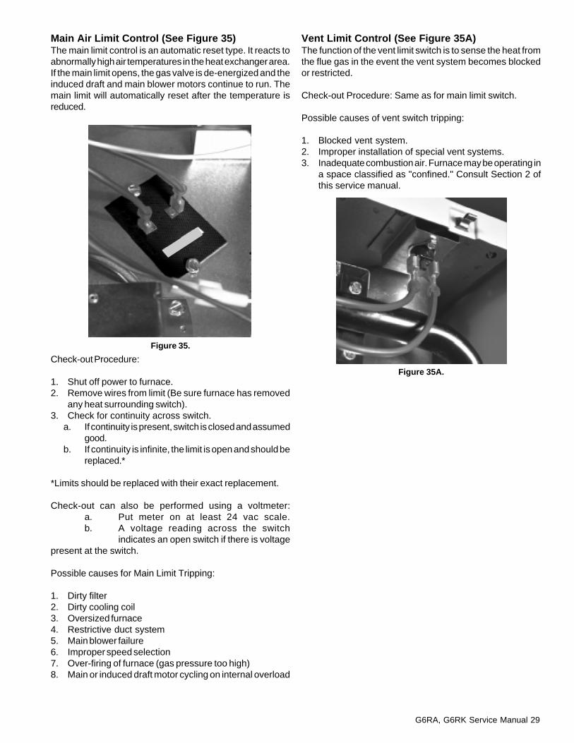
Main Air Limit Control (See Figure 35)The main limit control is an automatic reset type. It reacts toabnormally high air temperatures in the heat exchanger area.If the main limit opens, the gas valve is de-energized and theinduced draft and main blower motors continue to run. Themain limit will automatically reset after the temperature isreduced.
Vent Limit Control (See Figure 35A)The function of the vent limit switch is to sense the heat fromthe flue gas in the event the vent system becomes blockedor restricted.
Check-out Procedure: Same as for main limit switch.
Possible causes of vent switch tripping:
1. Blocked vent system.2. Improper installation of special vent systems.3. Inadequate combustion air. Furnace may be operating in
a space classified as "confined." Consult Section 2 ofthis service manual.
Check-out Procedure:
1. Shut off power to furnace.2. Remove wires from limit (Be sure furnace has removed
any heat surrounding switch).3. Check for continuity across switch.
a. If continuity is present, switch is closed and assumedgood.
b. If continuity is infinite, the limit is open and should bereplaced.*
*Limits should be replaced with their exact replacement.
Check-out can also be performed using a voltmeter:a. Put meter on at least 24 vac scale.b. A voltage reading across the switch
indicates an open switch if there is voltagepresent at the switch.
Possible causes for Main Limit Tripping:
1. Dirty filter2. Dirty cooling coil3. Oversized furnace4. Restrictive duct system5. Main blower failure6. Improper speed selection7. Over-firing of furnace (gas pressure too high)8. Main or induced draft motor cycling on internal overload
Figure 35.
Figure 35A.

30 G6RA, G6RK Service Manual
Roll Out Limit Control (See Figure 36)The function of a roll out switch is to sense any flamesbacking out of the heat exchanger tubes. They are normallyclosed and are manually reset.
Check-out Procedure:
1. Shut off power supply to furnace.2. Remove wires from roll out switch.3. Using an ohmmeter, check out continuity across switch.4. An infinite reading indicates an open switch.5. Depress reset button to reset switch.6. Continuity or 0 ohms should now be read. If not, replace
switch.
Possible causes of roll out switches tripping:
1. Blocked heat exchanger (sooted)2. Loose heat exchanger tube3. Burner misaligned4. Supply air interfering with flame patterns5. Overfiring/too high gas pressure6. Insufficient combustion air
Draft Inducer Motor (See Figure 37.)All models use an induced draft combustion blower mountedon the outlet of the heat exchanger. Its purpose is to establisha draft (flow) through the heat exchanger, to insure that all flueproducts are carried outside the structure via the vent pipe.(See Figure 40.) The blower is driven by a 115V permanentsplit capacitor motor. The same (part #) blower is used on allmodels of all series.
Check-out Procedure:1. Disconnect Molex plug between control board and motor.2. Using the appropriate scale on a volt meter, insert probes
into plug coming from control board.3. Establish call for heat.4. If voltage is read, check fan capacitor. If fan capacitor is
okay, replace motor. (See Figure 38.)5. If no voltage is read, replace control.6. Check for debris in wheel preventing it from turning.
Figure 37.
Figure 38.
Figure 39.
Figure 36.
Pressure SwitchThe pressure switch verifies that the inducer is drawing thecombustion gases through the heat exchanger. (Figure 39.)
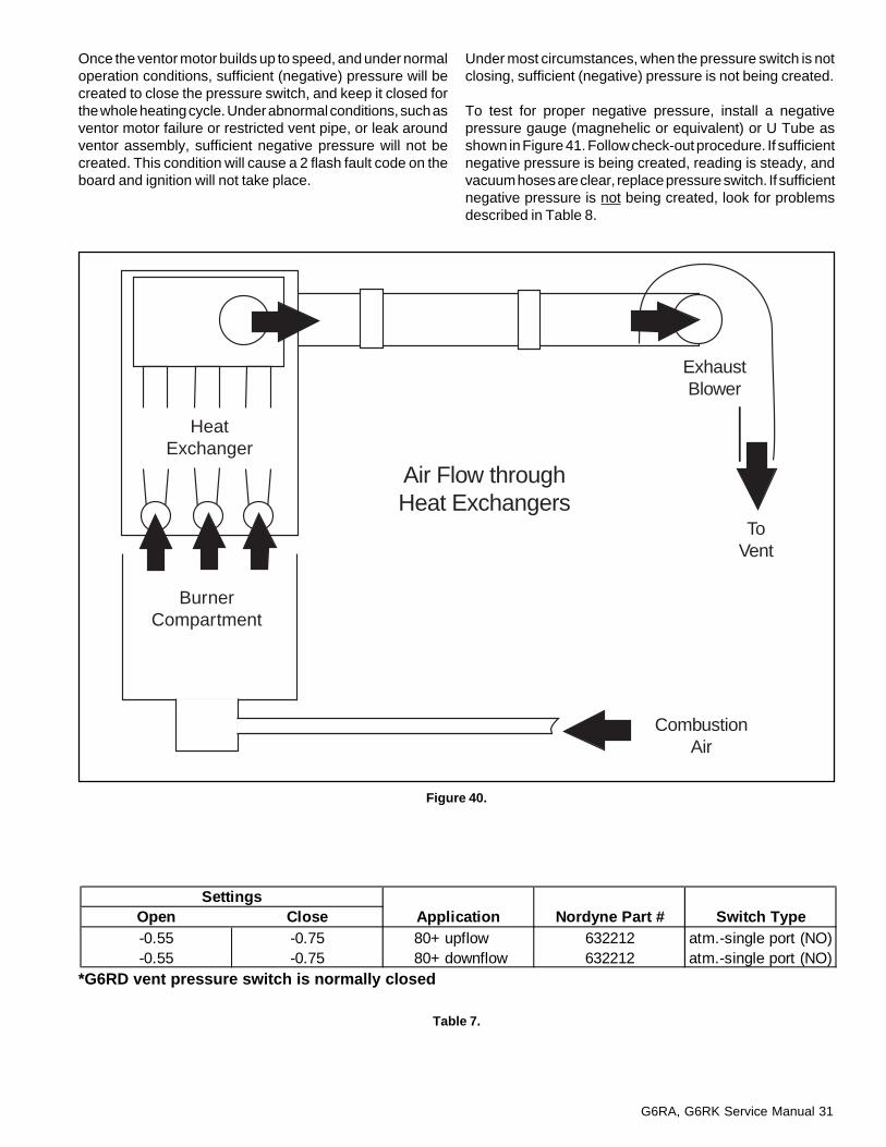
G6RA, G6RK Service Manual 31
Once the ventor motor builds up to speed, and under normaloperation conditions, sufficient (negative) pressure will becreated to close the pressure switch, and keep it closed forthe whole heating cycle. Under abnormal conditions, such asventor motor failure or restricted vent pipe, or leak aroundventor assembly, sufficient negative pressure will not becreated. This condition will cause a 2 flash fault code on theboard and ignition will not take place.
Under most circumstances, when the pressure switch is notclosing, sufficient (negative) pressure is not being created.
To test for proper negative pressure, install a negativepressure gauge (magnehelic or equivalent) or U Tube asshown in Figure 41. Follow check-out procedure. If sufficientnegative pressure is being created, reading is steady, andvacuum hoses are clear, replace pressure switch. If sufficientnegative pressure is not being created, look for problemsdescribed in Table 8.
Figure 40.
Table 7.
*G6RD vent pressure switch is normally closed
HeatExchanger
BurnerCompartment
ExhaustBlower
ToVent
CombustionAir
Air Flow throughHeat Exchangers
SettingsOpen Close Application Nordyne Part # Switch Type-0.55 -0.75 80+ upflow 632212 atm.-single port (NO)-0.55 -0.75 80+ downflow 632212 atm.-single port (NO)

32 G6RA, G6RK Service Manual
Check-out Procedure:1. Remove orange wires from pressure switch. Place a tee
in the hose connecting pressure switch to the inducerhousing.
2. Connect a Differential Pressure Gauge or InclinedManometer to tee.
3. Start induce draft motor.4. Negative pressure created by the induced draft motor
must be greater than 0.75" W.C. for switch to close. (SeeTable 7.)
5. Use an ohmmeter to check for continuity across switch.6. If continuity is established, switch is closed. If ohmmeter
shows an infinite reading, switch is open, and must bereplaced.
If the pressure reading will not pull down to 0.75" W.C., thenthere could be several reasons why:
1. Vent blockage.2. Heat exchanger blockage.3. Poor seal on collector box to induced draft motor.4. Bad blower wheel in induced draft motor.5. Crack or hole in heat exchanger.
The switch must be open to be ready for the next heatingcycle. If switch remains closed, a flash code of 3 will beproduced by the control board.
Figure 41.
Lower (Lesser) Negative Pressure Than Closing Pressure
Lower than normal negative pressure measured at the combustion blower may be caused by:
1. Restriction on outlet side of combustion blower (blocked flue, debris or venting not properly supported or sloped)
2. Leak (lack of restriction) on inlet side. Inducer inlet leaking, inducer blower wheel loose, or leak in heat exchanger.
3. To test for restriction in vent pipe to verify problem is outside of furnace, disconnect vent for test period only and startfurnace. If furnace starts, look for problem in vent pipe. Reconnect after testing.
Table 8. Lower (Lesser) Differential Negative Pressure Than Closing Pressure
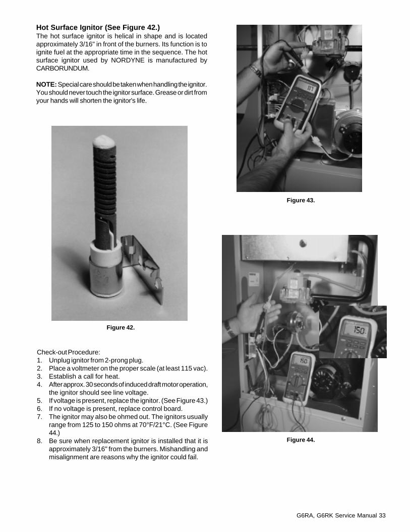
G6RA, G6RK Service Manual 33
Hot Surface Ignitor (See Figure 42.)The hot surface ignitor is helical in shape and is locatedapproximately 3/16" in front of the burners. Its function is toignite fuel at the appropriate time in the sequence. The hotsurface ignitor used by NORDYNE is manufactured byCARBORUNDUM.
NOTE: Special care should be taken when handling the ignitor.You should never touch the ignitor surface. Grease or dirt fromyour hands will shorten the ignitor's life.
Check-out Procedure:1. Unplug ignitor from 2-prong plug.2. Place a voltmeter on the proper scale (at least 115 vac).3. Establish a call for heat.4. After approx. 30 seconds of induced draft motor operation,
the ignitor should see line voltage.5. If voltage is present, replace the ignitor. (See Figure 43.)6. If no voltage is present, replace control board.7. The ignitor may also be ohmed out. The ignitors usually
range from 125 to 150 ohms at 70°F/21°C. (See Figure44.)
8. Be sure when replacement ignitor is installed that it isapproximately 3/16" from the burners. Mishandling andmisalignment are reasons why the ignitor could fail.
Figure 42.
Figure 43.
Figure 44.
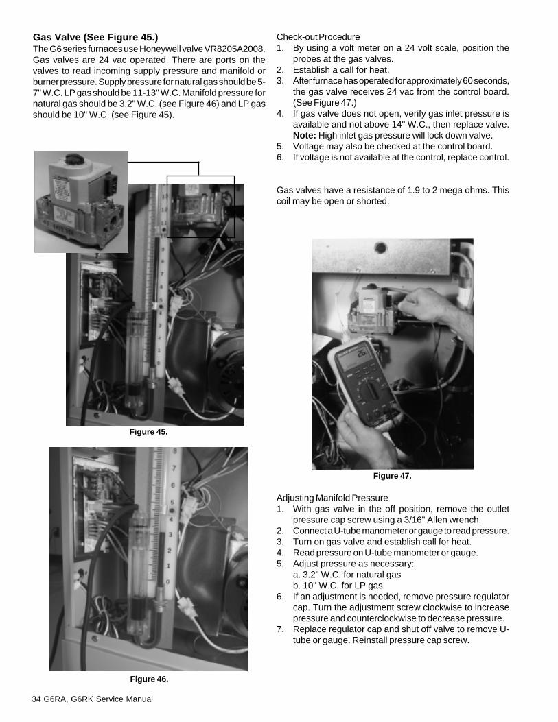
34 G6RA, G6RK Service Manual
Gas Valve (See Figure 45.)The G6 series furnaces use Honeywell valve VR8205A2008.Gas valves are 24 vac operated. There are ports on thevalves to read incoming supply pressure and manifold orburner pressure. Supply pressure for natural gas should be 5-7" W.C. LP gas should be 11-13" W.C. Manifold pressure fornatural gas should be 3.2" W.C. (see Figure 46) and LP gasshould be 10" W.C. (see Figure 45).
Check-out Procedure1. By using a volt meter on a 24 volt scale, position the
probes at the gas valves.2. Establish a call for heat.3. After furnace has operated for approximately 60 seconds,
the gas valve receives 24 vac from the control board.(See Figure 47.)
4. If gas valve does not open, verify gas inlet pressure isavailable and not above 14" W.C., then replace valve.Note: High inlet gas pressure will lock down valve.
5. Voltage may also be checked at the control board.6. If voltage is not available at the control, replace control.
Gas valves have a resistance of 1.9 to 2 mega ohms. Thiscoil may be open or shorted.
Figure 45.
Figure 46.
Adjusting Manifold Pressure1. With gas valve in the off position, remove the outlet
pressure cap screw using a 3/16" Allen wrench.2. Connect a U-tube manometer or gauge to read pressure.3. Turn on gas valve and establish call for heat.4. Read pressure on U-tube manometer or gauge.5. Adjust pressure as necessary:
a. 3.2" W.C. for natural gasb. 10" W.C. for LP gas
6. If an adjustment is needed, remove pressure regulatorcap. Turn the adjustment screw clockwise to increasepressure and counterclockwise to decrease pressure.
7. Replace regulator cap and shut off valve to remove U-tube or gauge. Reinstall pressure cap screw.
Figure 47.
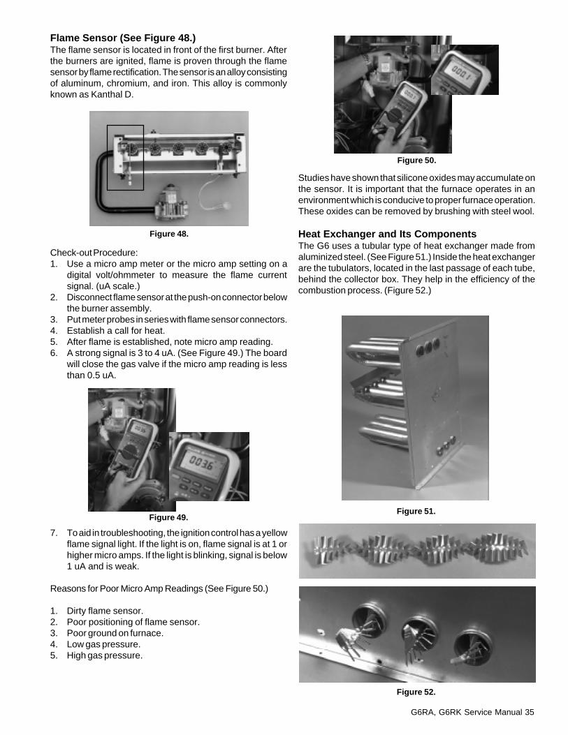
G6RA, G6RK Service Manual 35
Flame Sensor (See Figure 48.)The flame sensor is located in front of the first burner. Afterthe burners are ignited, flame is proven through the flamesensor by flame rectification. The sensor is an alloy consistingof aluminum, chromium, and iron. This alloy is commonlyknown as Kanthal D.
Check-out Procedure:1. Use a micro amp meter or the micro amp setting on a
digital volt/ohmmeter to measure the flame currentsignal. (uA scale.)
2. Disconnect flame sensor at the push-on connector belowthe burner assembly.
3. Put meter probes in series with flame sensor connectors.4. Establish a call for heat.5. After flame is established, note micro amp reading.6. A strong signal is 3 to 4 uA. (See Figure 49.) The board
will close the gas valve if the micro amp reading is lessthan 0.5 uA.
Studies have shown that silicone oxides may accumulate onthe sensor. It is important that the furnace operates in anenvironment which is conducive to proper furnace operation.These oxides can be removed by brushing with steel wool.
Heat Exchanger and Its ComponentsThe G6 uses a tubular type of heat exchanger made fromaluminized steel. (See Figure 51.) Inside the heat exchangerare the tubulators, located in the last passage of each tube,behind the collector box. They help in the efficiency of thecombustion process. (Figure 52.)
Figure 48.
7. To aid in troubleshooting, the ignition control has a yellowflame signal light. If the light is on, flame signal is at 1 orhigher micro amps. If the light is blinking, signal is below1 uA and is weak.
Reasons for Poor Micro Amp Readings (See Figure 50.)
1. Dirty flame sensor.2. Poor positioning of flame sensor.3. Poor ground on furnace.4. Low gas pressure.5. High gas pressure.
Figure 49.
Figure 50.
Figure 51.
Figure 52.
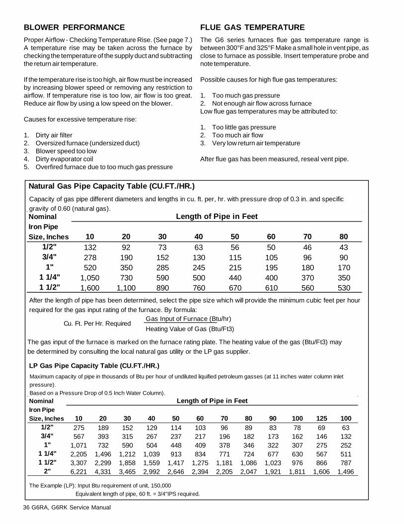
36 G6RA, G6RK Service Manual
LP Gas Pipe Capacity Table (CU.FT./HR.)
Nominal Length of Pipe in FeetIron PipeSize, Inches 10 20 30 40 50 60 70 80 90 100 125 100
1/2" 275 189 152 129 114 103 96 89 83 78 69 633/4" 567 393 315 267 237 217 196 182 173 162 146 1321" 1,071 732 590 504 448 409 378 346 322 307 275 252
1 1/4" 2,205 1,496 1,212 1,039 913 834 771 724 677 630 567 5111 1/2" 3,307 2,299 1,858 1,559 1,417 1,275 1,181 1,086 1,023 976 866 787
2" 6,221 4,331 3,465 2,992 2,646 2,394 2,205 2,047 1,921 1,811 1,606 1,496
Maximum capacity of pipe in thousands of Btu per hour of undiluted liquified petroleum gasses (at 11 inches water column inlet
pressure).
Based on a Pressure Drop of 0.5 Inch Water Column).
The Example (LP): Input Btu requirement of unit, 150,000
Equivalent length of pipe, 60 ft. = 3/4"IPS required.
BLOWER PERFORMANCE
Proper Airflow - Checking Temperature Rise. (See page 7.)A temperature rise may be taken across the furnace bychecking the temperature of the supply duct and subtractingthe return air temperature.
If the temperature rise is too high, air flow must be increasedby increasing blower speed or removing any restriction toairflow. If temperature rise is too low, air flow is too great.Reduce air flow by using a low speed on the blower.
Causes for excessive temperature rise:
1. Dirty air filter2. Oversized furnace (undersized duct)3. Blower speed too low4. Dirty evaporator coil5. Overfired furnace due to too much gas pressure
FLUE GAS TEMPERATURE
The G6 series furnaces flue gas temperature range isbetween 300°F and 325°F Make a small hole in vent pipe, asclose to furnace as possible. Insert temperature probe andnote temperature.
Possible causes for high flue gas temperatures:
1. Too much gas pressure2. Not enough air flow across furnaceLow flue gas temperatures may be attributed to:
1. Too little gas pressure2. Too much air flow3. Very low return air temperature
After flue gas has been measured, reseal vent pipe.
Natural Gas Pipe Capacity Table (CU.FT./HR.)
Nominal Length of Pipe in FeetIron PipeSize, Inches 10 20 30 40 50 60 70 80
1/2" 132 92 73 63 56 50 46 433/4" 278 190 152 130 115 105 96 901" 520 350 285 245 215 195 180 170
1 1/4" 1,050 730 590 500 440 400 370 3501 1/2" 1,600 1,100 890 760 670 610 560 530
Gas Input of Furnace (Btu/hr)
Heating Value of Gas (Btu/Ft3)
Capacity of gas pipe different diameters and lengths in cu. ft. per, hr. with pressure drop of 0.3 in. and specific
gravity of 0.60 (natural gas).
After the length of pipe has been determined, select the pipe size which will provide the minimum cubic feet per hour
required for the gas input rating of the furnace. By formula:
Cu. Ft. Per Hr. Required
The gas input of the furnace is marked on the furnace rating plate. The heating value of the gas (Btu/Ft3) may
be determined by consulting the local natural gas utility or the LP gas supplier.

G6RA, G6RK Service Manual 37
Figure 53. Typical Gas Service Connection
G6RA&K Typical Left Side EntryCAUTION:!Do not re-drill the burner orifices. If the orificesize must be changed, use only new orifices.
GAS CONVERSION AND HIGH ALTITUDE DERATE
High Altitude DerateThe nameplate input rating for the furnaces apply for elevationsup to 2,000 feet (610m) above sea level. For elevations over2,000 feet, reduce the input by 4% for each 1,000 feet abovesea level. For example, a furnace applied at an elevation of5,000 feet should be derated by 20%. See Table 10 describingthe correct orifice for derate.
NOTE: The density of air decreases with increasing elevationabove sea level. This reduces the quantity of combustion airdrawn into the furnace under normal operation and requiresthe unit to be derated by using smaller gas orifices or lowermanifold pressure.
ConversionConversion of this furnace to utilize LP/propane gasmust be made by qualified service personnel, using onlyfactory authorized or approved parts.
Verifying and Adjusting Firing RateThe firing rate must be verified for each installation to preventover-firing of the furnace.
IMPORTANT NOTE:The firing rate must not exceed the rate shown on
the furnace rating plate. At altitudes above2,000 feet it must not exceed that on the ratingplate less 4% for each 1,000 feet.
G6RA&K- Right Side Entry
BurnerAssembly
Manifold
Automatic GasValve (with manual
shut-off)
Ground JointUnion
Dripleg
Shut-Off Valvewith 1 8 NPTplugged tap
BurnerAssembly
Manifold
Some utilitiesrequire Shut-Off
Valve to be4 to 5 feet
above floor
Automatic GasValve (with manual
shut-off)
EXAMPLE 1
Elevation 3,890 feetType of gas NaturalFurnace model G6RA096( )16Orifice as shipped #42 Drill
What burner orifices are needed?
The required input for 3890 feet is 81,000 Btu/h or 16% lessthan the sea level rating of 96,000 Btu/h.
See Table 10 for natural gas, find the Furnace Model Numberand follow across the table for the elevation 2000-4000column. From the table, choose a #43 orifice. Install a #43orifice in every burner and check firing rate per VERIFYINGAND ADJUSTING FIRING RATE section. The firing rate inthis example must not exceed 81,000 Btu/h.
EXAMPLE 2
Elevation 5,500 feetType of gas PropaneFurnace model G6RA096( )-16Orifice in Natural to LPConversion Kit # 55 drill
What burner orifices are needed?
The required input for 5500 feet is 73,000 Btu/h or 24% lessthan the sea level rating of 96,000 Btu/h.
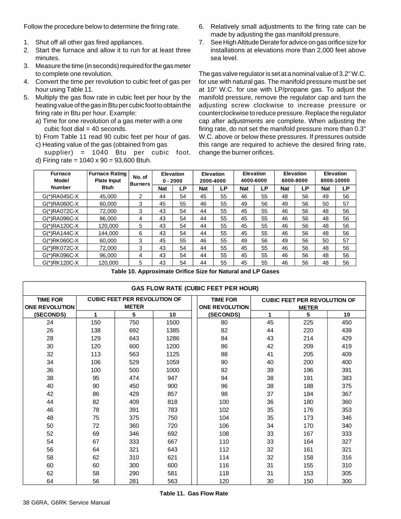
38 G6RA, G6RK Service Manual
TIME FOR TIME FORONE REVOLUTION ONE REVOLUTION
(SECONDS) 1 5 10 (SECONDS) 1 5 1024 150 750 1500 80 45 225 45026 138 692 1385 82 44 220 43928 129 643 1286 84 43 214 42930 120 600 1200 86 42 209 41932 113 563 1125 88 41 205 40934 106 529 1059 90 40 200 40036 100 500 1000 92 39 196 39138 95 474 947 94 38 191 38340 90 450 900 96 38 188 37542 86 429 857 98 37 184 36744 82 409 818 100 36 180 36046 78 391 783 102 35 176 35348 75 375 750 104 35 173 34650 72 360 720 106 34 170 34052 69 346 692 108 33 167 33354 67 333 667 110 33 164 32756 64 321 643 112 32 161 32158 62 310 621 114 32 158 31660 60 300 600 116 31 155 31062 58 290 581 118 31 153 30564 56 281 563 120 30 150 300
GAS FLOW RATE (CUBIC FEET PER HOUR)
CUBIC FEET PER REVOLUTION OF METER
CUBIC FEET PER REVOLUTION OF METER
Table 11. Gas Flow Rate
Table 10. Approximate Orifice Size for Natural and LP Gases
Follow the procedure below to determine the firing rate.
1. Shut off all other gas fired appliances.2. Start the furnace and allow it to run for at least three
minutes.3. Measure the time (in seconds) required for the gas meter
to complete one revolution.4. Convert the time per revolution to cubic feet of gas per
hour using Table 11.5. Multiply the gas flow rate in cubic feet per hour by the
heating value of the gas in Btu per cubic foot to obtain thefiring rate in Btu per hour. Example:a) Time for one revolution of a gas meter with a one
cubic foot dial = 40 seconds.b) From Table 11 read 90 cubic feet per hour of gas.c) Heating value of the gas (obtained from gas
supplier) = 1040 Btu per cubic foot.d) Firing rate = 1040 x 90 = 93,600 Btuh.
6. Relatively small adjustments to the firing rate can bemade by adjusting the gas manifold pressure.
7. See High Altitude Derate for advice on gas orifice size forinstallations at elevations more than 2,000 feet abovesea level.
The gas valve regulator is set at a nominal value of 3.2" W.C.for use with natural gas. The manifold pressure must be setat 10" W.C. for use with LP/propane gas. To adjust themanifold pressure, remove the regulator cap and turn theadjusting screw clockwise to increase pressure orcounterclockwise to reduce pressure. Replace the regulatorcap after adjustments are complete. When adjusting thefiring rate, do not set the manifold pressure more than 0.3"W.C. above or below these pressures. If pressures outsidethis range are required to achieve the desired firing rate,change the burner orifices.
Nat LP Nat LP Nat LP Nat LP Nat LPG(*)RA045C-X 45,000 2 44 54 45 55 46 55 48 56 49 56G(*)RA060C-X 60,000 3 45 55 46 55 49 56 49 56 50 57G(*)RA072C-X 72,000 3 43 54 44 55 45 55 46 56 48 56G(*)RA096C-X 96,000 4 43 54 44 55 45 55 46 56 48 56G(*)RA120C-X 120,000 5 43 54 44 55 45 55 46 56 48 56G(*)RA144C-X 144,000 6 43 54 44 55 45 55 46 56 48 56G(*)RK060C-X 60,000 3 45 55 46 55 49 56 49 56 50 57G(*)RK072C-X 72,000 3 43 54 44 55 45 55 46 56 48 56G(*)RK096C-X 96,000 4 43 54 44 55 45 55 46 56 48 56G(*)RK120C-X 120,000 5 43 54 44 55 45 55 46 56 48 56
Furnace Model
Number
Furnace RatingPlate Input
Btuh
No. ofBurners
Elevation0 - 2000
Elevation2000-4000
Elevation4000-6000
Elevation6000-8000
Elevation8000-10000

G6RA, G6RK Service Manual 39
Figure 54. Gas Valve and Manifold
Figure 55. Dual Fuel Kit
Figure 56. Electronic Air Cleaner
ACCESSORIES
ACCESSORIES
Dual Fuel Kit (Figure 55)
This kit, P/N 914762 is used when a fossil fuel furnace isbeing used with a heat pump.
Natural Gas to Propane Conversion KitsNORDYNE offers natural gas to propane conversion kits instandard P/N 902995 and high altitudes P/N 902996.
Electronic Air Cleaner (Figure 56)NORDYNE offers an Electronic Air Cleaner for installation onall G6 series furnaces. These units are powered from thefurnace's integrated control board.

40 G6RA, G6RK Service Manual
WHITE CLEAR RED
G6RA 072C-16 G6RA144C-20 G6RA 060C-12G6RA 096C-20 G6RA 144N-20 G6RA 072C-12G6RA 072N-16 G6RA 144C-20-H G6RA 096C-16G6RA 096N-20 G6RA 144E-20 G6RA 120C-16G6RA 072C-16-H G6RA 120C-20G6RA 096C-20-H G6RA 060N-12
G6RA 072N-12G6RA 096N-16G6RA 120N-16G6RA 120N-20G6RA 060C-12-HG6RA 072C-12-HG6RA 096C-16-HG6RA 120C-16-HG6RA 120C-20-HG6RK 060C-12G6RK 072C-12G6RK 072C-16G6RK 096C-12G6RK 096C-16G6RK 120C-20G6RK 060C-12-HG6RK 072C-12-HG6RK 072C-16-HG6RK 096C-12-HG6RK 096C-16-HG6RK 120C-20-HG6RA 072E-12G6RA 096E-16G6RA 120E-20
NOTE: For G6RA 045C-08 NO Bleed Tube Used.
VENT KIT #903196BLEED TUBE CHART
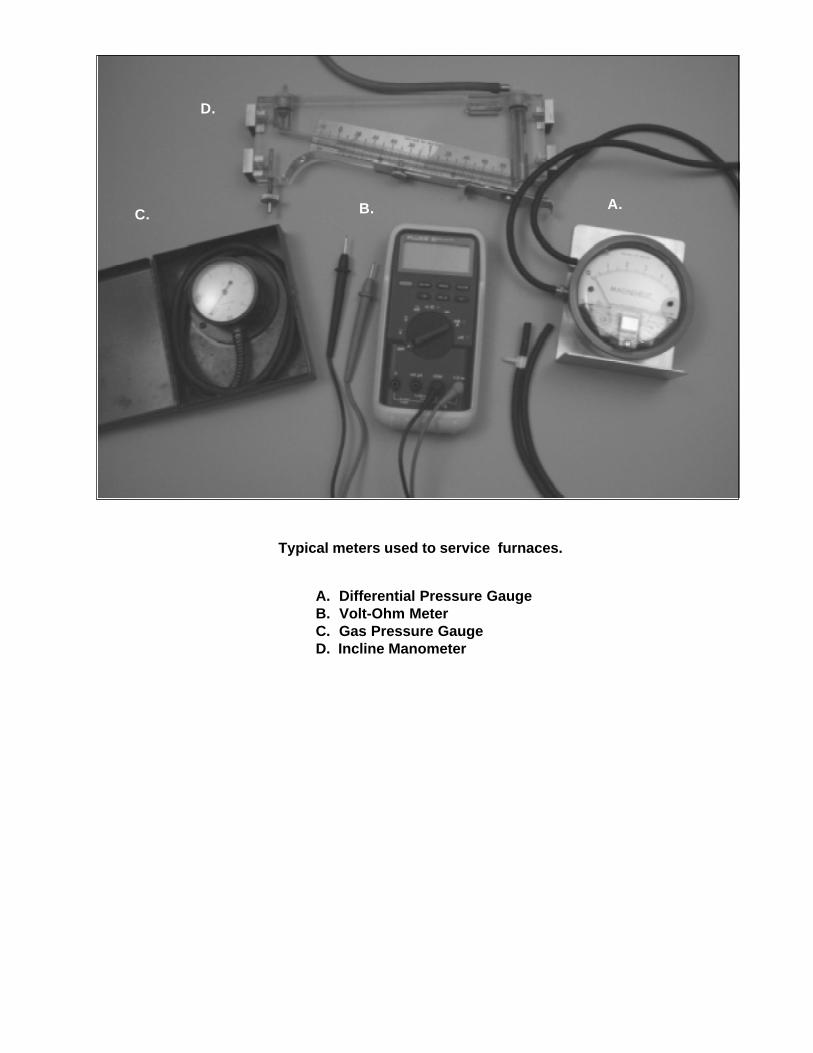
Typical meters used to service furnaces.
A. Differential Pressure GaugeB. Volt-Ohm MeterC. Gas Pressure GaugeD. Incline Manometer
A.B.C.
D.

St. Louis, MO
Specifications and illustrations subject to changewithout notice and without incurring obligations.
Printed in U.S.A. (12/97)
407A-0298