Embed Size (px)
Citation preview

Model 3150 DownflowService Manual
IMPORTANT: Fill in Pertinent Information on Page 3 for Future Reference
Table of Contents
IMPORTANT PLEASE READ: • Theinformation,specificationsandillustrationsinthismanualarebasedonthelatestinformationavailableatthetimeof
printing.Themanufacturerreservestherighttomakechangesatanytimewithoutnotice.• Thismanualisintendedasaguideforserviceofthevalveonly.Systeminstallationrequiresinformationfromanumberof
suppliersnotknownatthetimeofmanufacture.Thisproductshouldbeinstalledbyaplumbingprofessional.• Thisunitisdesignedtobeinstalledonpotablewatersystemsonly.• Thisproductmustbeinstalledincompliancewithallstateandmunicipalplumbingandelectricalcodes.Permitsmaybe
requiredatthetimeofinstallation.• Ifdaytimeoperatingpressureexceeds80psi,nighttimepressuresmayexceedpressurelimits.Apressurereducingvalvemust
beinstalled.• Donotinstalltheunitwheretemperaturesmaydropbelow32°F(0°C)orabove125°F(52°C).• Donotplacetheunitindirectsunlight.Blackunitswillabsorbradiantheatincreasinginternaltemperatures.• Donotstrikethevalveoranyofthecomponents.• Warrantyofthisproductextendstomanufacturingdefectsofthevesselandcontroller,notthemembrane.Misapplicationofthis
productmayresultinfailuretoproperlyconditionwater,ordamagetoproduct.• Aprefiltershouldbeusedoninstallationsinwhichfreesolidsarepresent.• InsomeapplicationslocalmunicipalitiestreatwaterwithChloramines.HighChloraminelevelsmaydamagevalvecomponents.• Correctandconstantvoltagemustbesuppliedtothecontrolvalvetomaintainproperfunction.
ContentsInstallationInstructions....................................................................................................................................................4Start-UpInstructions........................................................................................................................................................53200TimerSettingProcedure.........................................................................................................................................63210TimerSettings.........................................................................................................................................................73200&3210TimerSeries...............................................................................................................................................83200TimeClockTimerAssembly.................................................................................................................................103210MeterDelayedTimerAssembly............................................................................................................................123220MeterImmediateTimerAssembly........................................................................................................................143230RemoteStartTimerAssembly..............................................................................................................................16ControlValveAssembly.................................................................................................................................................18ControlDriveAssembly.................................................................................................................................................201800SeriesBrineSystemAssembly.............................................................................................................................222"BrassMeterAssembly..............................................................................................................................................24ServiceValveOperatorAssembly.................................................................................................................................252350SafetyBrineValveAssembly................................................................................................................................26Troubleshooting.............................................................................................................................................................28GeneralServiceHintsForMeterControl......................................................................................................................29WaterConditionerFlowDiagrams.................................................................................................................................30FlowData&InjectorDrawRates..................................................................................................................................32DimensionalDrawing.....................................................................................................................................................33InstallationDrawings.....................................................................................................................................................36System#4Immediate/DelayedRegenerationValveWiring..........................................................................................38System#4RemoteSignalStartValveWiring...............................................................................................................39System#5DuplexValveWiring....................................................................................................................................40System#6DuplexValveWiring....................................................................................................................................41System#7Duplex24V/120V3-WayValveWiring......................................................................................................42System#7Duplex230V3-WayValveWiring................................................................................................................43ServiceAssemblies.......................................................................................................................................................44

Page3
Installation & Start-Up ChecklistJobNumber:__________________
ModelNumber:________________
WaterHardness:___________________ppmorgpg
CapacityPerUnit:______________
MineralTankSize:___________Diameter:___________Height:
SaltSettingperRegeneration:_____________________________________________
1. Type of Timer: A. 7Dayor12Day B.MeterInitiated
2. Downflow: Upflow Upflow Variable 3. Meter Size: A. 3/4”StdRange(125-2,100gallonsetting)
B. 3/4”ExtRange(625-10,625gallonsetting)
C. 1”StdRange(310-5,270gallonsetting)
D. 1”ExtRange(1,150-26,350gallonsetting)
E. 1-1/2”StdRange(625-10,625gallonsetting)
F. 1-1/2”ExtRange(3,125-53,125gallonsetting)
G. 2”StdRange(1,250-21,250gallonsetting)
H. 2”ExtRange(6,250-106,250gallonsetting)
I. 3”StdRange(3,750-63,750gallonsetting)
J. 3”ExtRange(18,750-318,750gallonsetting)
K. Electronic________PulseCount________MeterSize
4. System Type: A. System#4:1Tank,1Meter,Immediate,orDelayedRegeneration
B. System#4:TimeClock
C. System#4:TwinTank
D. System#5:2-5Tanks,2Meters,Interlock
E. System#6:2-5Tanks,1Meter,SeriesRegeneration
F. System#7:2-5Tanks,1Meter,Alternating(Electronic2ValvesMax)
G. System#9:ElectronicOnly,2-4Tanks,MeterperValve,Alternating
H. System#14:ElectronicOnly,2-4Tanks,MeterperValve.Bringsunitsonandofflinebasedonflow.
5. Timer Program Settings: A. Backwash:______________________Minutes
B. BrineandSlowRinse:_____________Minutes
C. RapidRinse:____________________ Minutes
D. BrineTankRefill:_________________ Minutes
E. PauseTime:____________________ Minutes
F. SecondBackwash:_______________ Minutes
6. Drain Line Flow Control: ____________gpm 7. Brine Line Flow Controller:__________________gpm 8. Injector Size#: _____________________ 9. Piston Type: A. HardWaterBypass
B. NoHardWaterBypass

Page4
Installation Instructions
WATER PRESSURE:Aminimumof20pounds(1.4bar)ofwaterpressureisrequiredforregenerationvalvetooperateeffectively.
ELECTRICAL FACILITIES:Anuninterruptedalternatingcurrent(A/C)supplyisrequired.Note:Othervoltagesareavailable.Pleasemakesureyourvoltagesupplyiscompatiblewithyourunitbeforeinstallation.
EXISTING PLUMBING:Conditionofexistingplumbingshouldbefreefromlimeandironbuildup.Pipingthatisbuiltupheavilywithlimeand/orironshouldbereplaced.Ifpipingiscloggedwithiron,aseparateironfilterunitshouldbeinstalledaheadofthewatersoftener.
LOCATION OF SOFTENER AND DRAIN:Thesoftenershouldbelocatedclosetoadraintopreventairbreaksandbackflow.
BY-PASS VALVES:Alwaysprovidefortheinstallationofaby-passvalveifunitisnotequippedwithone.CAUTION:Waterpressureisnottoexceed125psi(8.6bar),watertemperatureisnottoexceed110°F(43°C),andtheunitcannotbesubjectedtofreezingconditions.
Installation Instructions1. Placethesoftenertankwhereyouwanttoinstalltheunitmakingsuretheunitislevelandonafirmbase.
2. Duringcoldweather,theinstallershouldwarmthevalvetoroomtemperaturebeforeoperating.
3. Allplumbingshouldbedoneinaccordancewithlocalplumbingcodes.Thepipesizeforresidentialdrainlineshouldbeaminimumof1/2"(13mm).Backwashflowratesinexcessof7gpm(26.5Lpm)orlengthinexcessof20'(6m)require3/4"(19mm)drainline.Commercialdrainlinesshouldbethesamesizeasthedrainlineflowcontrol.
4. Refertothedimensionaldrawingforcuttingheightofthedistributortube.Ifthereisnodimensionaldrawing,cutthedistributortubeflushwiththetopofthetank.
5. LubricatethedistributorO-ringsealandtankO-ringseal.Placethemaincontrolvalveontank.Note:Onlyusesiliconelubricant.
6. SolderjointsnearthedrainmustbedonepriortoconnectingtheDrainLineFlowControlfitting(DLFC).Leaveatleast6"(15cm)betweentheDLFCandsolderjointswhensolderingpipesthatareconnectedontheDLFC.FailuretodothiscouldcauseinteriordamagetotheDLFC.
7. Teflontapeistheonlysealanttobeusedonthedrainfitting.Thedrainfromtwintankunitsmayberunthroughacommonline.
8. Makesurethattheflooriscleanbeneaththesaltstoragetankandthatitislevel.
9. Placeapproximately1"(25mm)ofwaterabovethegridplate.Ifagridisnotutilized,filltothetopoftheaircheck(Figure1)inthesalttank.Donotaddsalttothebrinetankatthistime.
10. Onunitswithabypass,placeinby-passposition.Turnonthemainwatersupply.Openacoldsoftwatertapnearbyandletrunafewminutesoruntilthesystemisfreefromforeignmaterial(usuallysolder)thatmayhaveresultedfromtheinstallation.Onceclean,closethewatertap.
11. Slowlyplacethebypassinservicepositionandletwaterflowintothemineraltank.Whenwaterflowstops,slowlyopenacoldwatertapnearbyandletrununtiltheairispurgedfromtheunit.
12. Plugunitintoanelectricaloutlet.Note:Allelectricalconnectionsmustbeconnectedaccordingtolocalcodes.Becertaintheoutletisuninterrupted.
BR60002-REVE
Figure 1 Residential Air Check Valve
CAUTION• Do not exceed 125 psi (8.6 bar) water pressure.• Do not exceed 110°F (43°C) water temperature.• Do not subject unit to freezing conditions.

Page5
Start-Up Instructions
Thewatersoftenershouldbeinstalledwiththeinlet,outlet,anddrainconnectionsmadeinaccordancewiththemanufacturer’srecommendations,andtomeetapplicableplumbingcodes.
1. Turnthemanualregeneratonknobslowlyinaclockwisedirectionuntiltheprogrammicroswitchliftsontopofthefirstsetofpins.Allowthedrivemotortomovethepistontothefirstregenerationstepandstop.Eachtimetheprogramswitchpositionchanges,thevalvewilladvancetothenextregenerationstep.Alwaysallowthemotortostopbeforemovingtothenextsetofpinsorspaces.NOTE: For electronic valves, please refer to the manual regeneration part of the timer operation section. If the valve came with a separate electronic timer service manual, refer to the timer operation section of the electronic timer service manual.
2. Positionthevalvetobackwash.Ensurethedrainlineflowremainssteadyfor10minutesoruntilthewaterrunsclear(seeabove).
3. Positionthevalvetothebrine/slowrinseposition.Ensuretheunitisdrawingwaterfromthebrinetank(thisstepmayneedtoberepeated).
4. Positionthevalvetotherapidrinseposition.Checkthedrainlineflow,andrunfor5minutesoruntilthewaterrunsclear.
5. Positionthevalvetothestartofthebrinetankfillcycle.Ensurewatergoesintothebrinetankatthedesiredrate.Thebrinevalvedrivecamwillholdthevalveinthispositiontofillthebrinetankforthefirstregeneration.
6. Replacecontrolboxcover.
7. Putsaltinthebrinetank.NOTE: Do not use granulated or rock salt.

Page6
3200 Timer Setting Procedure
How To Set Days On Which Water Conditioner Is To Regenerate:Rotatetheskipperwheeluntilthenumber“1”isattheredpointer.Setthedaysthatregenerationistooccurbyslidingtabsontheskipperwheeloutwardtoexposetripfingers.Eachtabisoneday.Fingeratredpointeristonight.Movingclockwisefromtheredpointer,extendorretractfingerstoobtainthedesiredregenerationschedule.
How To Set The Time Of Day:1. Pressandholdtheredbuttonintodisengagethe drivegear.2. Turnthelargegearuntiltheactualtimeofdayisat thetimeofdaypointer.3. Releasetheredbuttontoagainengagethedrive gear.
How To Manually Regenerate Your Water Conditioner At Any Time:1. Turnthemanualregenerationknobclockwise.2. Thisslightmovementofthemanualregeneration knobengagestheprogramwheelandstartsthe regenerationprogram.3. Theblackcenterknobwillmakeonerevolutionin thefollowingapproximatelythreehoursandstopin thepositionshowninthedrawing.4. Eventhoughittakesthreehoursforthiscenterknob tocompleteonerevolution,theregenerationcycleof yourunitmightbesetonlyonehalfofthistime.5. Inanyevent,conditionedwatermaybedrawnafter rinsewaterstopsflowingfromthewater conditionerdrainline.
How to Adjust Regeneration Time:1. Disconnectthepowersource.2. Locatethethreescrewsbehindthemanual regenerationknobbypushingtheredbuttoninand rotatingthe24hourdialuntileachscrewappearsin thecutoutportionofthemanualregenerationknob.3. Looseneachscrewslightlytoreleasethepressure onthetimeplatefromthe24hourgear.4. Locatetheregenerationtimepointerontheinside ofthe24hourdialinthecutout.5. Turnthetimeplatesothedesiredregenerationtime alignsnexttotheraisedarrow.6. Pushtheredbuttoninandrotatethe24hourdial. Tighteneachofthethreescrews.7. Pushtheredbuttonandlocatethepointeronemore timetoensurethedesiredregenerationtime iscorrect.8. Resetthetimeofdayandrestorepowertotheunit.
61502_3200REVA

Page7
3210 Timer Settings
Typical Programming Procedure
Calculatethegalloncapacityofthesystem,subtractthenecessaryreserverequirementandsetthegallonsavailableoppositethesmallwhitedotontheprogramwheelgear.
NOTE:Drawingshows8,750gallonsetting.Thecapacity(gallons)arrow(15)showszerogallonsremaining.Theunitwillregeneratetonightatthesetregenerationtime.
How To Set The Time Of Day:
1. Pressandholdtheredbuttonintodisengagethedrivegear.
2. Turnthelargegearuntiltheactualtimeofdayisoppositethetimeofdaypointer.
3. Releasetheredbuttontoagainengagethedrivegear.
How To Manually Regenerate Your Water Conditioner At Any Time:
1. Turnthemanualregenerationknobclockwise.2. Thisslightmovementofthemanualregeneration
knobengagestheprogramwheelandstartstheregenerationprogram.
Theblackcenterknobwillmakeonerevolutioninthefollowingapproximatelythreehoursandstopinthepositionshowninthedrawing.3. Eventhoughittakesthreehoursforthiscenterknob
tocompleteonerevolution,theregenerationcycleofyourunitmightbesetforonlyonehalfofthistime.
4. Inanyevent,conditionedwatermaybedrawnafterrinsewaterstopsflowingfromthewaterconditionerdrainline.
Immediate Regeneration Timers:
Thesetimersdonothavea24hourgear.Settingthegallonsontheprogramwheelandmanualregenerationprocedurearethesameaspreviousinstructions.Thetimerwillregenerateassoonasthecapacitygallonsreacheszero.
NOTE:Theprogramwheeltotheleftmaybedifferentthantheprogramwheelontheproduct.
NOTE:Tosetmetercapacityrotatemanualknobone-360°revolutiontosetgallonage.
Figure 361502_3200REVA

Page8
3200 & 3210 Timer Series
How To Set The Regeneration Cycle Program:
Theregenerationcycleprogramonyourwaterconditionerhasbeenfactorypreset,however,portionsofthecycleorprogrammaybelengthenedorshortenedintimetosuitlocalconditions.
3200 & 3210 Series Timers (Figure 4)
1. Toexposecycleprogramwheel,grasptimerinupperleft-handcornerandpull,releasingsnapretainerandswingingtimertotheright.
2. Tochangetheregenerationcycleprogram,theprogramwheelmustberemoved.Graspprogramwheelandsqueezeprotrudinglugstowardcenter,liftprogramwheelofftimer.Switcharmsmayrequiremovementtofacilitateremoval.
3. Returntimertoclosedpositionengagingsnapretainerinbackplate.Makecertainallelectricalwireslocateabovesnapretainerpost.
Timer Setting Procedure for 3200 & 3210 Timer
How To Change The Length Of The Backwash Time:
Theprogramwheelasshowninthedrawingisintheserviceposition.Asyoulookatthenumberedsideoftheprogramwheel,thegroupofpinsstartingatzerodeterminesthelengthoftimeyourunitwillbackwash.
EXAMPLE:Iftherearesixpinsinthissection,thetimeofbackwashwillbe12min.(2min.perpin).Tochangethelengthofbackwashtime,addorremovepinsasrequired.Thenumberofpinstimestwoequalsthebackwashtimeinminutes.
How To Change The Length Of Brine And Rinse Time:
1. Thegroupofholesbetweenthelastpininthebackwashsectionandthesecondgroupofpinsdeterminesthelengthoftimethatyourunitwillbrineandrinse(2min.perhole).
2. Tochangethelengthofbrineandrinsetime,movetherapidrinsegroupofpinstogivemoreorfewerholesinthebrineandrinsesection.Numberofholestimestwoequalsbrineandrinsetimeinminutes.
How To Change The Length Of Rapid Rinse:
1. Thesecondgroupofpinsontheprogramwheeldeterminesthelengthoftimethatyourwaterconditionerwillrapidrinse(2min.perpin).
2. Tochangethelengthofrapidrinsetime,addorremovepinsatthehighernumberedendofthissectionasrequired.Thenumberofpinstimestwoequalstherapidrinsetimeinminutes.
How To Change The Length Of Brine Tank Refill Time:
1. Thesecondgroupofholesintheprogramwheeldeterminesthelengthoftimethatyourwaterconditionerwillrefillthebrinetank(2min.perhole).
2. Tochangethelengthofrefilltime,movethetwopinsattheendofthesecondgroupofholesasrequired.
3. Theregenerationcycleiscompletewhentheoutermicroswitchistrippedbythetwopinsetatendofthebrinetankrefillsection.
4. Theprogramwheel,however,willcontinuetorotateuntiltheinnermicro-switchdropsintothenotchontheprogramwheel.
Regeneration Cycle Program Setting Procedure (Downflow)
Figure 4 61502_3210REVA

Page9
Notes

Page10
3200 Time Clock Timer Assembly
61502-3200_REVA
For Service Assembly Numbers, See the Back of this Manual

Page11
3200 Time Clock Timer Assembly
For Service Assembly Numbers, See the Back of this Manual
Item No. Quantity Part No. Description 1.................. 1.....................13870.......................Housing,Timer,3200 2.................. 1.....................14265.......................Clip,Spring 3.................. 3.....................14087....................... Insulator 4.................. 1.....................10896.......................Switch,Micro 5.................. 1.....................15320.......................Switch,Micro,Timer 6.................. 2.....................11413........................Screw,PanHdMach,4-40x11/8 7.................. 1.....................13886.......................Knob,3200 8.................. 5.....................13296.......................Screw,HexWsh,6-20x1/2 9.................. 1.....................11999........................ Label,Button 10................ 1.....................13018.......................Pinion,Idler 11................ 1.....................13312.......................Spring,IdlerShaft 12................ 1.....................13017.......................Gear,Idler 13................ 1.....................13164.......................Gear,Drive 14................ 1.....................13887.......................Plate,MotorMounting 15................ 1.....................18743-1....................Motor,120V,60Hz,1/30rpm,5600 ............................................19659-1....................Motor,24V,60Hz,1/30rpm 16................ 2.....................13278.......................Screw,SltdFillisterHd6-32x.156 17................ 1.....................15424.......................Spring,Detent,Timer 18................ 1.....................15066.......................Ball,1/4",Delrin 19................ 1.....................15465....................... Label,Caution 20................ 1.....................19210.......................ProgramWheelAssembly 21................ 1.....................13911........................Gear,MainDrive,Timer 22................ 17...................41754.......................Pin,Spring,1/16x5/8StainlessSteel,Timer 23................ 1.....................13011........................Arm,CycleActuator 24................ 1.....................13864.......................Ring,SkipperWheel 25................ 2.....................13311........................Spring,Detent,Timer 26................ 2.....................13300.......................Ball,1/4",StainlessSteel 27................ 1.....................14381.......................SkipperWheelAssembly,12Day ............................................14860.......................SkipperWheelAssembly,7Day 28................ 1.....................13014.......................Pointer,Regeneration 29................ 1.....................40096-24..................Dial,12AMRegenAssembly,Black ............................................40096-02..................Dial,2AMRegenAssembly,Black 30................ 1.....................13881.......................Bracket,HingerTimer 31................ 2.....................11384........................Screw,Phil,6-32x1/4Zinc 32................ 1.....................13902.......................Harness,3200 33................ 2.....................40422.......................Nut,Wire,Tan 34................ 1.....................15354-01..................Wire,Ground,4" 35................ 1.....................14007....................... Label,TimeofDay

Page12
3210 Meter Delayed Timer Assembly
61502-3210_REVA
For Service Assembly Numbers, See the Back of this Manual

Page13
3210 Meter Delayed Timer Assembly
Item No. Quantity Part No. Description 1.................. 1.....................13870.......................Housing,Timer,3200 2.................. 1.....................13802.......................Gear,CycleActuator 3.................. 1.....................40096-02..................Dial2AMRegenAssembly,Black 4.................. 1.....................13886.......................Knob,3200 5..................4.....................13296.......................Screw,HexWsh,6-20x1/2 6.................. 2.....................11999........................ Label,Button 7.................. 1.....................60405-50..................ProgramWheel,w/2"StdLabel,w/PeopleLabelSet@21 8.................. 1.....................13806.......................Retainer,ProgramWheel 9.................. 1.....................13748.......................Screw,FlatHeadSt,6-20x1/2 10................ 1.....................14265.......................Clip,Spring 11................ 1.....................15424.......................Spring,Detent,Timer 12................ 1.....................15066.......................Ball,1/4”Delrin 13................ 1.....................13018.......................Pinion,Idler 14................ 1.....................13312.......................Spring,IdlerShaft 15................ 1.....................13017.......................Gear,Idler 16................ 1.....................13164.......................Gear,Drive 17................ 1.....................13887.......................Plate,MotorMounting 18................ 1.....................18743-1....................Motor,120V,60Hz1/30rpm,5600 19................ 1.....................13278.......................Screw,FillisterHd,6-32x.156 20................ 1.....................13830.......................Pinion,ProgramWheelDrive 21................ 1.....................13831.......................Clutch,DrivePinion 22................ 1.....................14276.......................Spring,Meter,Clutch 23................ 1.....................14253.......................Retainer,ClutchSpring 24................ 3.....................11384........................Screw,Phil,6-32x1/4 25................ 1.....................13881.......................Bracket,HingeTimer 26................ 3.....................14087....................... Insulator 27................ 1.....................10896.......................Switch,Micro 28................ 1.....................15320.......................Switch,Micro,Timer 29................ 2.....................11413........................Screw,PanHdMach,4-40x11/8 30................ 1.....................14198....................... Label,Indicator 31................ 1.....................15465....................... Label,Caution 32................ 1.....................14007....................... Label,TimeofDay 33................ 1.....................14045....................... Label,Instruction 34................ 1.....................13902.......................Harness,3200 35................ 2.....................40422.......................Nut,Wire,Tan 36................ 1.....................15354-01..................Wire,Ground,4" 37................ 1.....................19210.......................ProgramWheelAssembly 38................ 17...................41754.......................Pin,Spring,1/16x5/8StainlessSteel,Timer 39................ 1.....................13911........................Gear,MainDrive,Timer 40................ 1.....................15354-01..................Wire,Ground4"
For Service Assembly Numbers, See the Back of this Manual

Page14
3220 Meter Immediate Timer Assembly
1
2
3
4
5
6
7
8
9
1011
1213
14
15
16
1718 19
20
2122
2324
25
26
27
28
29
30
31
32
33
3435
36 5
1
23
23
21
4
BR61502_3220REVB

Page15
3220 Meter Immediate Timer Assembly
Item No. Quantity Part No. Description 1.................. 1.....................13870.......................Housing,Timer 2.................. 1.....................15431.......................Gear,CycleActuator,System#5 3.................. 1.....................13886.......................Knob,3200 4..................4.....................13296.......................Screw,HexWsh,6-20x1/2 5.................. 2.....................11999........................ Label,Button 6.................. 1.....................60408-50..................ProgramWheel,W/2"StdLabel 7.................. 1.....................13806.......................Retainer,ProgramWheel 8.................. 1.....................13748.......................Screw,FltHdSt,6-20x1/2 9.................. 1.....................14265.......................SpringClip 10................ 1.....................13018.......................Pinion,Idler 11................ 1.....................18563....................... IdlerShaftSpring 12................ 1.....................13017.......................Gear,Idler 13................ 1.....................13164.......................DriveGear 14................ 1.....................13887.......................Plate,MotorMounting 15................ 1.....................18743-1....................Motor,120V,60Hz,1/30rpm,5600 16................ 2.....................13278.......................Screw,SltdFillisterHead 17................ 1.....................14502.......................Pinion,ProgramWheel 18................ 1.....................14501.......................Clutch,DrivePinion 19................ 1.....................14276.......................MeterClutchSpring 20................ 1.....................14253.......................Retainer,ClutchSpring 21................ 3.....................11384........................Screw,Phil,6-32x1/4Zinc 22................ 1.....................13881.......................Bracket,HingeTimer 23................ 3.....................14087....................... Insulator 24................ 1.....................15414-00..................MicroSwitch 25................ 1.....................15320.......................Switch,Micro,Timer 26................ 2.....................11413........................Screw,PanHdMach,4-40x1-1/8 27................ 1.....................14198....................... Label,Indicator 28................ 1.....................15465....................... Label,Caution 29................ 1.....................14007....................... Label,TimeofDay 30................ 1.....................15148....................... Label,Instruction 31................ 1.....................40617.......................Harness,3220 32................ 2.....................40422.......................Nut,Wire,Tan 33................ 1.....................15354-01..................Wire,Ground,4" 34................ 1.....................19210-05..................ProgramWheelAssembly,9000/3230 35................ 17...................41754.......................Pin,Spring,1/16x5/8StainlessSteel,Timer 36................ 1.....................15055.......................Gear,MainDrive

Page16
3230 Remote Start Timer Assembly
1
2
3
4
5
6
7
8
9
10
1112
13
14
15
16
17
18
20
8
8
3
3
24
24
24
23
21
25 2627
22
BR61502_3230REVC

Page17
3230 Remote Start Timer Assembly
Item No. Quantity Part No. Description 1.................. 1.....................13870.......................Housing,Timer 2.................. 1.....................14265.......................SpringClip 3.................. 3.....................14087....................... Insulator 4.................. 1.....................15314.......................MicroSwitch 5.................. 1.....................15320.......................Switch,Micro,Timer 6.................. 2.....................11413........................Screw,PanHdMach,4-40x1-1/8 7.................. 1.....................13886.......................Knob,3200 8..................4.....................13296.......................Screw,HexWsh,6-20x1/2 9.................. 1.....................11999........................ Label,Button 10................ 1.....................13018.......................Pinion,Idler 11................ 1.....................18563....................... IdlerShaftSpring 12................ 1.....................13017.......................Gear,Idler 13................ 1.....................15055.......................DriveGear 14................ 1.....................13887.......................Plate,MotorMounting 15................ 1.....................18743-1....................Motor,120V,60Hz,1/10rpm .................... 1.....................19659-1....................Motor,24V,60Hz,1/30rpm 16................ 2.....................13278.......................Screw,SltdFillisterHd 17................ 1.....................15313....................... Label,Caution 18................ 1.....................19210-05..................ProgramWheelAssembly,3200 20................ 1.....................15055.......................MainDriveGear 21................ 17...................41754.......................Pin,Spring,1/16x5/8StainlessSteel,Timer 22................ 1.....................13011........................CycleActuatorArm 23................ 1.....................13881.......................Bracket,HingeTimer 24................ 3.....................11384........................Screw,Phil,6-32x1/4Zinc 25................ 1.....................16336.......................Harness,3230R 26................ 2.....................40422.......................Nut,Wire,Tan 27................ 1.....................15354-01..................Wire,Ground,4"

Page18
Control Valve Assembly
For Service Assembly Numbers, See the Back of this Manual
11
10
1
12
3
4
3
2
2
3
4 2
2
5
6 7
8 9
13
14
15
23
61500-3150_REVB
1617
18
1920
21
22
61414_REVB

Page19
Control Valve Assembly
Item No. Quantity Part No. Description 1....................1..................... 15114....................... ValveBody,3150 2....................8..................... 11720....................... Seal,Piston,2900/3150 3....................5..................... 10369....................... Spacer,2",2900/3150 16141....................... Spacer,PortRing,HW,180° 4....................2..................... 10368....................... Spacer,Narrow,3150/3900 10368-01.................. Spacer,QuadRing,Brass,HW,180° 5....................1..................... 16130....................... Piston,HighBackwash 19611-01.................. PistonAssy,3150,NHWBP,O-ring 6....................1..................... 14818....................... Ring,PistonRod,Snap 7....................1..................... 15125....................... Rod,Piston,3150 19708....................... Rod,Piston,3150NHWBP 8....................1..................... 14922....................... O-ring,-035,Piston 9....................1..................... 16398-01.................. EndPlugAssy,3150,White 16398-11.................. EndPlugAssy,3150,Black 10..................1..................... 15112....................... Seal,3150AdapterBase 11..................1..................... 17407....................... Adapter,3150,Sidemount 12..................2..................... 40118....................... Screw,ScktHd,1/2-13Unc
Options ▲13..............1..................... 15117-01.................. Adapter,3150,Machined *▲14.............1..................... 15247....................... O-ring,-229 ▲15..............1..................... 13575....................... O-ring,-240 15210....................... O-ring,-343,ParkTank *▲16.............1..................... 19608-20.................. Disperser,Commercial,2",3150
Options 16..................1..................... 40316....................... Adapter,Sidemount 17..................1..................... 16804-01.................. O-ring,-150 18..................1..................... 40368....................... O-ring,-160,Sidemount,Flange 19..................1..................... 40365....................... Base,3130/3150,Rotating 20..................7..................... 40375....................... Washer,Flat,3/8,TypeA 21..................7..................... 19768....................... Screw,HexHd,3/8-16x1,Cap18-8 22..................1..................... 61414....................... AdapterAssy,Sidemount,3150,Rotating 23..................1..................... 61418....................... AdapterAssy,Sidemount,3150,Fixed
NotShown..................1..................... 60113-01.................. PistonAssy,3150,NHWBP,D/Flow ................................................................................ Conversion/Replacement ......................1..................... 60106-00.................. PistonAssy,3900/3150STD
*Notusedwitharotatingsidemount.▲Notusedwithafixedsidemount.
For Service Assembly Numbers, See the Back of this Manual

Page20
24
22191215181617252627
4313
146
20
7
11
5
8
21
39
40
9
44 45 46 41 42 3
1
38
37
3635
34
32
30
31
29281533
4
232
Control Drive Assembly
For Service Assembly Numbers, See the Back of this Manual
61501-3150_REVB

Page21
Control Drive Assembly Item No. Quantity Part No. Description 1.................... 1......................19304-04..................................Backplate,3150/3900,Upper 2.................... 1......................15120-01..................................Bracket,MotorMtg,3150/3900Environmental 3.................... 2......................16346........................................Nut,Hex,Jam,5/16-18 4.................... 1......................40392........................................Motor,Drive,115V,50/60Hz,Sp 40390........................................Motor,Drive,220V,50Hz,Sp,Fam3 42581........................................Motor,Drive,24VAC/DC,50-60Hz,Fam3 5.................... 1......................17797........................................Bracket,SwitchMounting,3150/3900 6.................... 4......................10302........................................ Insulator,LimitSwitch 7.................... 3......................10218........................................Switch,Micro 8.................... 1......................17845-03..................................Pin,Hinge,3150/3900,Env 9.................... 4......................11235........................................Nut,Hex,1/4-20,MachScrew,Zinc 10.................. 2......................13365........................................Washer,Lock,#4,External 11................... 2......................40080........................................Screw,RdHd,4-40x11/2" 12.................. 1......................16053........................................Bracket,BrineSide 13.................. 2......................40133........................................Screw,PanHd,4-40x1/4 14.................. 1......................15226-6....................................TerminalBlock 15.................. 2......................16052........................................Bushing,3150/3900 16.................. 1......................16059........................................Washer,SS,.88,3150/3900 17.................. 1......................16051........................................Ring,Retaining,Bowed 18.................. 2......................10300........................................Screw,SlotHexWsh,18-8x3/8 19.................. 4......................10231........................................Screw,SlotHex,1/4-20x1/2 20.................. 2......................14202-01..................................Screw,HexWshHd,8x5/16 21.................. 1......................10475-01..................................Wire,Ground 22.................. 1......................16494-03..................................CamAssy,3150/3900SignalAfterBrineFill 16494-05..................................CamAssy,3150/3900UpperSignalAfterRapidRinse 23.................. 4......................11224........................................Screw,HexHd,5/16-18x5/8 24.................. 1......................60240-02..................................CoverAssy,3150/3900Env,Black 25.................. 2......................41084........................................TerminalBlock,Segment,Gray 26.................. 1......................41085........................................Endplate,TerminalBloack,Gray 27.................. 1......................40174........................................TerminalBlock,Green/Yellow 28.................. 1......................16046........................................Gear,Drive 29.................. 1......................16050........................................Ring,Retaining 30.................. 1......................11774........................................Ring,Retaining 31.................. 1......................16047........................................Link,Drive 32.................. 1......................11709........................................Pin,DriveLink 33.................. 1......................16048........................................Bearing,DriveLink 34.................. 1......................11898........................................Clip,3150/3900 35.................. 1......................16045........................................Pinion,Drive 36.................. 1......................11381........................................Pin,Roll,2900/3900 37.................. 1......................11080........................................Screw,FltHdMach,8-32x3/8 38.................. 3......................10872........................................Screw,HexWsh,8-32x17/64 39.................. 1......................40084-12..................................PowerCord,12’US,Round,120V 40.................. 1......................17967........................................FittingAssy,LiquidTight,Blk 41.................. 1......................19691........................................Plug,.750Dia,Recessed,Black 42.................. 3......................19591........................................Plug,.8750Hole,Recessed,Black 43.................. 2......................15250........................................Label,TerminalStrip 44.................. 10....................19800........................................Plug,.140Dia,White 45.................. 1......................15806........................................Plug,Hole,Heyco#2693 46.................. 1......................17421........................................Plug,1.20Hole NotShown..... 1......................17470........................................CableGuideAssy,2850/3150 NotShown..... 1......................19856........................................Ring,Retaining(UsedonCover) NotShown..... 1........................................................................Timer(SeeTimerSection) NotShown..... 1......................40396........................................Harness,Drive,Environmental NotShown..... 1......................16427-04..................................Wire,Lead,12",White NotShown..... 1......................40396........................................Harness,Drive,Environmental NotShown..... 1......................14924........................................StrainReliefHeyco#1247 NotShown..... 1......................15513........................................MeterCable,17.5"
*SpecifynumberofterminalsFor Service Assembly Numbers, See the Back of this Manual

Page22
1800 Series Brine System Assembly
For Service Assembly Numbers, See the Back of this Manual
60036_REVC

Page23
1800 Series Brine System Assembly
Item No. Quantity Part No. Description 1....................1..................... 16340....................... Body,Injector,1800D/F 2....................1..................... 15128-xx.................. InjectorNozzle 3....................1..................... 15127-xx.................. InjectorThroat 4....................3..................... 15246....................... O-ring,-116 5....................1..................... 16341-01.................. Cap,Injector,1800 6....................8..................... 12473....................... Screw,HexWsh,10-24x5/8 7....................1..................... 16341-02.................. Plug,Injector,1800 8....................1..................... 19054....................... O-ring,-021,560CD 9....................1..................... 16497-01.................. StemAssy,1800,BrineValve 10..................1..................... 18713....................... BrineValveBody,1800 11..................1..................... 11772....................... Spring,3150BrineValve 12..................1..................... 11774....................... Ring,Retaining 13..................1..................... 16498-01.................. StemGuideAssy,Brine 14..................1..................... 16387....................... Plug,Pipe,1/2"NPT 15..................2..................... 18702....................... Fitting,Tube,1/2NPT5/8 16..................1..................... 18703....................... Tube,Brine,5/8ODAnnealed 17..................1..................... 60009-00.................. AirCheck,#900,CommercialLessFittings 60009-01.................. AirCheck,#900,Commercial,HWLessFittings NotShown....1....................................................... FlowControl(SpecifyFlowRate)
Option Without Brine Valve 1............................... 16605.......... RetainerPlate 1............................... 19860.......... Fitting,BrineValve,1800 Delete: Items 9 through 16 Injector Throat 15127-04.................. #4................Green 15127-05.................. #5................ Red 15127-06.................. #6................White 15127-07.................. #7................ Blue 15127-08.................. #8................ Yellow 15127-09.................. #9................ Violet 15127-10.................. #10.............. Black
Injector Nozzle 15128-04.................. #4................Green 15128-05.................. #5................ Red 15128-06.................. #6................White 15128-07.................. #7................ Blue 15128-08.................. #8................ Yellow 15128-09.................. #9................ Violet 15128-10.................. #10.............. Black
For Service Assembly Numbers, See the Back of this Manual

Page24
2" Brass Meter Assembly
Item No. Quantity Part No. Description 1....................1..................... 12112....................... Screw,HexHdMach,10-24x1/2 15886....................... Screw,HexHd,M5x12 21716....................... Screw,M5x16 12473....................... Screw,HexWsh,10-24x5/8 2....................1..................... 15218....................... MeterCapAssy,3/4to2",STD,BRS,PDL 15218NP.................. MeterCapAssy,3/4to2",STD,Nickel,PDL 14038....................... MeterCapAssy,3/4to2",STD,Plastic,PDL 15150....................... MeterCapAssy,3/4to2",EXT,PlasticPDL 3....................1..................... 13847....................... O-ring,-137,Std/560CD,Meter 4....................1..................... 15374-01.................. Impeller,2"Meter 5....................1..................... 15432....................... Shaft,Impeller,SS 6....................1..................... 15532....................... Seat,ImpellerShaft,Hex 7....................1..................... 14456....................... Body,Meter,2" 14456-20.................. Body,Meter,2",BSP,Metric 14456-20NP............. Body,Meter,2",BSP,Mtrc,NP 60627NP.................. MeterAssy,2",NP 8....................1..................... 14679....................... O-ring,-227,Meter 9....................1..................... 14568....................... Fitting,Nipple,2" 14568-10.................. Fitting,Nipple,2",BSP,Brass 14568-10NP............. Fitting,Nipple,2",BSP,Brass,NP 10..................1..................... 14680....................... FlowStraightener 11..................1..................... 14569....................... Nut,2900Meter 14569NP.................. Nut,2900Meter,NP 60393....................... MeterAssy,2"Inline,NPT,STD,BRS,BDY,PDL 60394....................... MeterAssy,2"Inline,NPT,EXT,BRS,BDY,PDL
For Service Assembly Numbers, See the Back of this Manual
60393_REVE
Page25
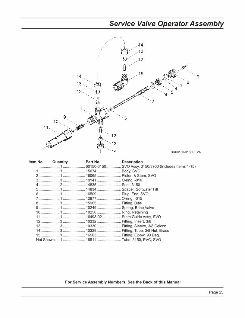
Service Valve Operator Assembly
Item No. Quantity Part No. Description ......................1..................... 60150-3150.............. SVOAssy,3150/3900(IncludesItems1-15) 1....................1..................... 15074....................... Body,SVO 2....................1..................... 16065....................... Piston&Stem,SVO 3....................1..................... 10141....................... O-ring,-010 4....................2..................... 14835....................... Seal,3150 5....................1..................... 14834....................... Spacer,SoftwaterFill 6....................1..................... 16509....................... Plug,End,SVO 7....................1..................... 12977....................... O-ring,-015 8....................1..................... 15965....................... Fitting,Bias 9....................1..................... 10249....................... Spring,BrineValve 10..................1..................... 10250....................... Ring,Retaining 11..................1..................... 16498-02.................. StemGuideAssy,SVO 12..................3..................... 10332....................... Fitting,Insert,3/8 13..................3..................... 10330....................... Fitting,Sleeve,3/8Celcon 14..................3..................... 10329....................... Fitting,Tube,3/8Nut,Brass 15..................1..................... 16503....................... Fitting,Elbow,90Deg. NotShown....1..................... 16511....................... Tube,3150,PVC,SVO
For Service Assembly Numbers, See the Back of this Manual
BR60150-3150REVA

Page26
2350 Safety Brine Valve Assembly
Item No. Quantity Part No. Description 1....................1..................... 60038....................... SafetyBrineValve,2350 1A..................1..................... 61024....................... ActuatorAssembly,2350Brine 2....................1..................... 60028-30.................. FloatAssembly,2350,30"Wht 3....................1..................... 60009-00.................. AirCheck,#900,CommercialLessFittings
Not Shown: ......................1..................... 18603....................... FittingAssembly,900AirCheck2350 ......................1..................... 18602....................... FittingAssembly,900AirCheck
42303_REVA
For Service Assembly Numbers, See the Back of this Manual

Page27
Notes

Page28
Troubleshooting
Problem Cause Correction1.Waterconditionerfailstoregenerate.
A.Electricalservicetounithasbeeninterrupted
A.Assurepermanentelectricalservice(checkfuse,plug,pullchain,orswitch)
B.Timerisdefective. B.Replacetimer.C.Powerfailure. C.Resettimeofday.
2.Hardwater. A.Bypassvalveisopen. A.Closeby-passvalve.B.Nosaltisinbrinetank. B.Addsalttobrinetankandmaintainsalt
levelabovewaterlevel.C.Injectorscreenplugged. C.Cleaninjectorscreen.D.Insufficientwaterflowingintobrinetank.
D.Checkbrinetankfilltimeandcleanbrinelineflowcontrolifplugged.
E.Hotwatertankhardness. E.Repeatedflushingsofthehotwatertankisrequired.
F.Leakatdistributortube. F.Makesuredistributortubeisnotcracked.CheckO-ringandtubepilot.
G.Internalvalveleak. G.Replacesealsandspacersand/orpiston.
3.Unitusedtoomuchsalt. A.Impropersaltsetting. A.Checksaltusageandsaltsetting.B.Excessivewaterinbrinetank. B.Seeproblem7.
4.Lossofwaterpressure. A.Ironbuildupinlinetowaterconditioner.
A.Cleanlinetowaterconditioner.
B.Ironbuildupinwaterconditioner.
B.Cleancontrolandaddmineralcleanertomineralbed.Increasefrequencyofregeneration.
C.Inletofcontrolpluggedduetoforeignmaterialbrokenloosefrompipesbyrecentworkdoneonplumbingsystem.
C.Removepistonandcleancontrol.
5.Lossofmineralthroughdrainline.
A.Airinwatersystem. A.Assurethatwellsystemhasproperaireliminatorcontrol.Checkfordrywellcondition.
B.Improperlysizeddrainlineflowcontrol.
B.Checkforproperdrainrate.
6.Ironinconditionedwater. A.Fouledmineralbed. A.Checkbackwash,brinedraw,andbrinetankfill.Increasefrequencyofregeneration.Increasebackwashtime.
7.Excessivewaterinbrinetank. A.Pluggeddrainlineflowcontrol. A.Cleanflowcontrol.B.Pluggedinjectorsystem. B.Cleaninjectorandscreen.C.Timernotcycling. C.Replacetimer.D.Foreignmaterialinbrinevalve. D.Replacebrinevalveseatandclean
valve.E.Foreignmaterialinbrinelineflowcontrol.
E.Cleanbrinelineflowcontrol.

Page29
Troubleshooting
Problem Cause Correction8.Softenerfailstodrawbrine. A.Drainlineflowcontrolisplugged. A.Cleandrainlineflowcontrol.
B.Injectorisplugged. B.CleaninjectorC.Injectorscreenplugged. C.Cleanscreen.D.Linepressureistoolow. D.Increaselinepressureto20psi.E.Internalcontrolleak E.Changeseals,spacers,andpiston
assembly.F.Serviceadapterdidnotcycle. F.Checkdrivemotorandswitches.
9.Controlcyclescontinuously. A.Misadjusted,broken,orshortedswitch.
A.Determineifswitchortimerisfaultyandreplaceit,orreplacecompletepowerhead.
10.Drainflowscontinuously. A.Valveisnotprogrammingcorrectly.
A.Checktimerprogramandpositioningofcontrol.Replacepowerheadassemblyifnotpositioningproperly.
B.Foreignmaterialincontrol. B.Removepowerheadassemblyandinspectbore.Removeforeignmaterialandcheckcontrolinvariousregenerationpositions.
C.Internalcontrolleak. C.Replacesealsandpistonassembly.
General Service Hints For Meter ControlProblem: Softener delivers hard water
Reason: Reservecapacityhasbeenexceeded. Correction:Checksaltdosagerequirementsandresetprogramwheeltoprovideadditionalreserve. Reason: Programwheelisnotrotatingwithmeteroutput. Correction:Pullcableoutofmetercoverandrotatemanually.Programwheelmustmovewithoutbinding andclutchmustgivepositiveclickswhenprogramwheelstrikesregenerationstop.Ifitdoesnot,replace timer.
Reason: Meterisnotmeasuringflow. Correction: Checkmeterwithmeterchecker.

Page30
Water Conditioner Flow Diagrams
1 Service Position
2 Backwash Position 3 Brine and Slow Rinse Position

Page31
Water Conditioner Flow Diagrams
4 Rapid Rinse Position
5 Brine Tank Refill Position

Page32
Flow Data & Injector Draw Rates
TR20395

Page33
Dimensional Drawing
2.84
72.2
6.42
163
1.77
45
INLE
T
16.1
340
9.8
OU
TLE
T2"
NP
T O
R B
SP
2.24
56.9
3.85
97.7
3.25
82.6
5.39
136.
9
3.79
96.3
2" N
PT
OR
BS
PIN
LET
DR
AIN
2" N
PT
OR
BS
P
8.55
217
2.57
65.3
7.43
188.
8
16.1
641
0.5
8.82
224

Page34
Dimensional Drawing
10.6
927
1.5
16.1
641
0.5
1.77
45
6.42
163
4.68
118.
9
2.84
72.2
2" N
PT
OR
BS
PIN
LET
17.5
144
4.7
OU
TLE
T2"
NP
T O
R B
SP
2.24
56.9
3.75
95.2
2.14
54.4
3.25
82.6
3.85
97.7
3.75
95.2
8.55
217
45°
(EIT
HE
R S
IDE
OF
C L)
7.43
188.
8
2.57
65.3
C L
2" N
PT
OR
BS
P
DR
AIN
2" N
PT
OR
BS
PTO
P &
BO
TTO
M
TAN
K

Page35
Notes

Page36
Installation Drawings
System #4 - Typical Single Tank Installation with Optional Meter
System #5 - Interlock - Typical Twin Tank Installation with Optional Meter Interlock and No Hard Water Bypass

Page37
Installation Drawings
System #6 - Twin Series Regeneration Installation with a Remote Meter
System #7 - Twin Alternator Installation with a Remote Meter

Page38
System #4 Immediate/Delayed Regeneration Valve Wiring
18669_REVE
Page39
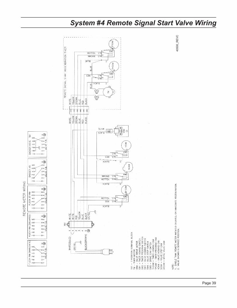
System #4 Remote Signal Start Valve Wiring
40500_REVC

Page40
System #5 Duplex Valve Wiring
18690-01_REVE
18690-02_REVE
Page41
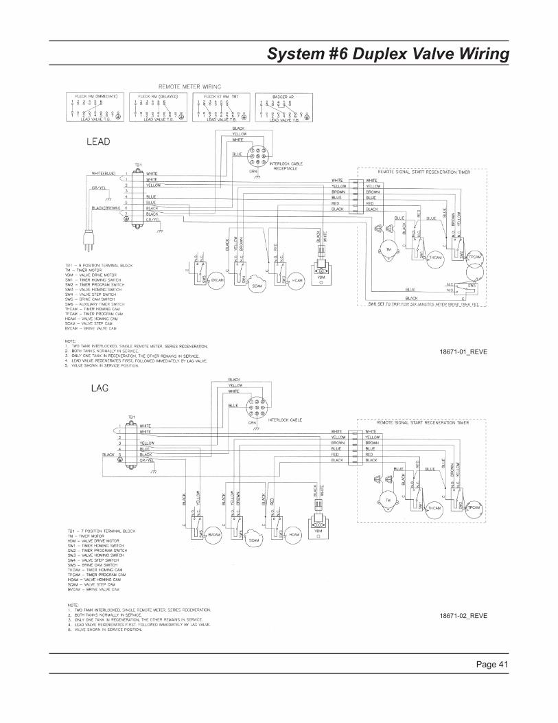
System #6 Duplex Valve Wiring
18671-01_REVE
18671-02_REVE

Page42
System #7 Duplex 24V / 120V 3-Way Valve Wiring
40503-01_REVC
40503-02_REVC

Page43
System #7 Duplex 230V 3-Way Valve Wiring
40504-01_REVC
40504-02_REVC

Page44
Service Assemblies
60036-02 Brine Valve, 1800, Design 3
1...... 11772........... Spring,3150BrineValve1...... 11774........... Ring,Retaining1...... 18713........... BrineValveBody,18001...... 16497-01...... StemAssy,1800BrineValve NewStyle1...... 16498-01...... StemGuideAssy,Brine
60277-xx ...... 1800 Injector Assembly
4...... 12473........... Screw,HexWsh,10-24x5/81...... 15127........... InjectorThroatAssy1...... 15128-xx...... InjectorNozzle-SpecifySize2...... 15246........... O-ring,-1161...... 16340........... Body,Injector,1800,D/F1...... 16341-01...... Cap,Injector,1800
60106-00 ...... Piston Assy, 3900/3150 Std
1...... 14818........... Ring,PistonRod,Snap1...... 14922........... O-ring,-035,Piston1...... 16130........... Piston,HighBackwash1...... 15125........... Rod,Piston,31501...... 16398-01...... EndPlugAssy,3150,White
60113-01 ...... Piston Assy, 3150, NHWBP, D-Flow Conversion/Replacement
1...... 16398-01...... EndPlugAssy,3150,White1...... 19611-01...... PistonAssy,3150,NHWBP,O-ring1...... 19708........... Rod,Piston,3150NHWBP1...... 14818........... Ring,PistonRod,Snap
60131 ........... Seal & Spacer Kit 2930/3130/3150
2...... 10368........... Spacer,Narrow,3150/39005...... 10369........... Spacer,2",2900/31508...... 11720........... Seal,Piston,2900/3150
60057-01 ...... Drive Assy, 3150, 120V, B/Fill 3900 Upper Sys #5 or Sys # 7
60057-11 ...... Drive Assy, 3150, 120V, 3900 Upper Sys #4 or Sys #6
60150-3150 .... SVO Assy, 3150
60393 ............. Meter Assy, 2900, 2" Std
60394 ............. Meter Assy, 2900, 2" Ext
Side Mount Adapter61414.................... Adapter,Assy,Sdmnt,3130/3150 Rotating61414NP............... AdapterAssy,Sdmnt,3130/3150 NickelPlatedRotating61418.................... AdapterAssy,Sdmnt,3150
60131-10 .. 3900 Upper Seal Kit:10368........ Spacer10369........ Spacer11720-02... Seal,1-1/2",Silicone
60038........ Safety Brine Valve, 2350:60028-30.. FloatAssembly,White60009-00.. #900AirCheck,LessFittings18602........ Kit,Fitting,1700Brine,900AirCheck18603........ Kit,Fitting,1700Brine,2350Safety
Drain Line Flow Controls (DLFC):60711-00... 2"NPT,LessBTTNS,w/2Holes60711-000. 2"NPT,LessBTTNS,w/3Holes60711-01... 2"NPT,LessBTTNS,w/1Hole60711-20... 2"NPT,20gpm60711-25... 2"NPT,25gpm,Brass60711-30... 2"NPT,30gpm60711-35... 2"NPT,35gpm60711-40... 2"NPT,40gpm60711-45... 2"NPT,45gpm60711-50... 2"NPT,50gpm60711-55... 2"NPT,55gpm60711-60... 2"NPT,60gpm60711-65... 2"NPT,65gpm60711-70... 2"NPT,70gpm60711-75... 2"NPT,75gpm60711-80... 2"NPT,80gpm60711-85... 2"NPT,85gpm60711-90... 2"NPT,90gpm60711-95... 2"NPT,95gpm60711-100. 2"NPT,100gpm
60812-30.. 2"BSP/Metric,30gpm60812-35.. 2"BSP/Metric,35gpm60812-45.. 2"BSP/Metric,45gpm60812-50.. 2"BSP/Metric,50gpm60812-55.. 2"BSP/Metric,55gpm60812-70.. 2"BSP/Metric,70gpm60812-75.. 2"BSP/Metric,75gpm60812-80.. 2"BSP/Metric,80gpm60812-90.. 2"BSP/Metric,90gpm60812-95.. 2"BSP/Metric,95gpm60812-100 2"BSP/Metric,100gpm

Page45
Service Assemblies
BLFC Assy1...... 60710-1.2..... BLFC,1"Fx1"M,NPT,1.2GPM1...... 60710-10...... BLFC,1"Fx1"M,NPT,10GPM1...... 60710-12...... BLFC,1"Fx1"M,NPT,12GPM1...... 60710-15...... BLFC,1"Fx1"M,NPT,15GPM1...... 60710-2.0..... BLFC,1"Fx1"M,NPT,2.0GPM1...... 60710-2.4..... BLFC,1"Fx1"M,NPT,2.4GPM1...... 60710-20...... BLFC,1"Fx1"M,NPT,20GPM1...... 60710-25...... BLFC,1"Fx1"M,NPT,25GPM1...... 60710-3.0..... BLFC,1"Fx1"M,NPT,3.0GPM1...... 60710-3.5..... BLFC,1"Fx1"M,NPT,3.5GPM1...... 60710-30...... BLFC,1"Fx1"M,NPT,30GPM1...... 60710-4.0..... BLFC,1"Fx1"M,NPT,4.0GPM1...... 60710-5.0..... BLFC,1"Fx1"M,NPT,5.0GPM1...... 60710-7.0..... BLFC,1"Fx1"M,NPT,7.0GPM1...... 60710-9.0..... BLFC,1"Fx1"M,NPT,9.0GPM

P/N16504Rev.E2-25-10