Embed Size (px)
Citation preview

internet: www.isoplus.orgEd
ition
: 16.
01.2
012
7.1 RigidandFlexibleCompoundSystems
7.1.1 One-Time-Compensator................................................................................... 7 / 1-27.1.2 Tapping-Branch................................................................................................ 7 / 3-47.1.3 One-Time-Ball-Valve......................................................................................... 7 / 57.1.4 End Cap............................................................................................................ 7 / 67.1.5 Wall Duct........................................................................................................... 7 / 77.1.6 Expansion Pads................................................................................................ 7 / 8-97.1.7 PUR-Foam........................................................................................................ 7 / 107.1.8 Joining Pipe / Assembling Supports / Warning Tape....................................... 7 / 11
7.2 SpecialAccessoriesFlexibleCompoundSystems
7.2.1 Press Tool / Bending Tool................................................................................ 7 / 127.2.2 Protection Cap / Distributing Manhole............................................................. 7 / 137.2.3 Twin-Accoutrement.......................................................................................... 7 / 14
7ACCESSORIES
7

Copy only after permission of isoplus Fernwärmetechnik Vertriebsgesellschaft mbH; modifications reserved
internet: www.isoplus.org 7 / 1
Ed
ition
: 16.
01.2
012
7.1 Rigid and Flexible Compound Systems
7.1.1 One-Time-Compensator
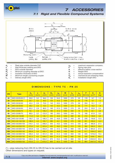
EKO (One-time-compensator) - system will be used for thermal pre-stressing of isoplus-pipelines in case of already refilled pipe-trenches. The distances of the pipelines between the one-time-compensators have to be filled, only the required assembling hollow at the EKO will remain open. Normally the thermal pre-stressing will be carried out by using the operating medium, however mobile heating units may be used as well.
EKO is a component which will be welded into the PJP-pipeline. During the heating period alterations of the pipe length will occur, which will be reliably compensated by this system. Due to the welding of the EKO-guiding pipes, the prestressing of the pipeline will be fixed after the expansion compensation will be completed.
One-time-compensators will be used in case where the maximum pipe laying length [Lmax] cannot be kept or/and natural expansion elements will be not possible due to lack of space. However a natural expansion side-leg (L-, Z- or U-elbow) should be provided at the beginning and at the end of an EKO-section, respectively an anchor may be provided at one side.
At the beginning or at the end of a section one-time-compensators cannot be used instead of L-, Z- or U-elbows for compensation of expansion. In order to reach the pre-stressing respectively the limitation of the axial tension at refilled pipe trenches, the EKO should be at the detention area. In case of trench sections smaller than the maximum permitted pipe-laying length an one-time-compensator will be ineffective. In case of designed mixed systems, i. e. EKO cold-laying can pipe-statically not determined.
Delivery length [LL] has to be shortened before installation of EKO´s about the mechanical pre-stressing measure [Vm] In that way the real expansion expected from the pipeline [ut] will be adjusted. For that the EKO has to be pressed together mechanical by use of a suitable gripping tool. On request EKO´s can be pre-stressed in the factory, starting from dimension DN 350 this will be made generally due to the high strengths.
Material: Bellow/inside pipe made of chromium-nickel-steel, material-No. 1.4541; welding ends, outside pipe and the like made of P235GH, material-No. 1.0345; delivery incl. inside-hexagon-screw with sealing; nominal pressure PN 25.
Dimensions EKO see following pageAssembling steps EKO see chapter 10.2.9
7 ACCESSORIES
Copy only after permission of isoplus Fernwärmetechnik Vertriebsgesellschaft mbH; modifications reserved
internet: www.isoplus.org7 / 2
Ed
ition
: 16.
01.2
012
da = Steel pipe outside diameter PJP um = maximum expansion compens.s = Wall thickness welding end EKO F = Spring rate axialda‘ = EKO-outside diameter A = effective bellow cross-sectionDa = Minimum-coupling diameter at EKO G = Weight EKOsD = Insulation thickness at EKO ut = actual expansion compensationM = Minimum length connecting coupler Vm = mechanical pre-stressing meas.LL = Delivery length EKO EL = Installation length EKO
7 ACCESSORIES7.1 Rigid and Flexible Compound Systems
(*) = pipe reducing from DN 25 to DN 20 has to be carried out at site.Other dimensions and types on request.
D I M E N S I O N S - T Y P E T C - P N 2 5
DN Typeda
[mm]s
[mm]da´
[mm]Da
[mm]sD
[mm]M
[mm]LL
[mm]um
[mm]F
[N/mm]A
[cm2]G
[kg]
20 EKO-25/25/50 (*) 26,9 3,2 56,0 125 34,5 1000 275 50 176 9,7 1,3
25 EKO-25/25/50 33,7 3,2 56,0 125 34,5 1000 275 50 176 9,7 1,3
32 EKO-25/32/50 42,4 2,6 73,0 140 33,5 1000 275 50 204 15,1 1,7
40 EKO-25/40/50 48,3 2,6 73,0 140 33,5 1000 275 50 177 16,3 1,8
50 EKO-25/50/50 60,3 2,9 86,0 160 37,0 1000 275 50 224 25,9 2,4
65 EKO-25/65/70 76,1 2,9 106,0 180 37,0 1000 335 70 219 42,1 3,8
80 EKO-25/80/70 88,9 3,2 122,0 180 29,0 1000 345 70 180 67,8 5,5
100 EKO-25/100/80 114,3 3,6 139,7 225 42,6 1200 390 80 212 109,9 9,8
125 EKO-25/125/80 139,7 3,6 168,3 250 40,8 1200 400 80 226 159,9 12,5
150 EKO-25/150/100 168,3 4,0 193,7 280 43,1 1200 475 100 261 230,5 14,5
200 EKO-25/200/120 219,1 4,5 268,0 355 43,5 1200 515 120 361 383,9 27,5
250 EKO-25/250/120 273,0 5,0 323,9 400 38,0 1200 515 120 362 594,0 35,0
300 EKO-25/300/140 323,9 5,6 355,6 450 47,2 1400 660 140 353 834,2 57,5
350 EKO-25/350/140 355,6 5,6 406,4 500 46,8 1400 650 140 617 1004,3 60,0
400 EKO-25/400/140 406,4 6,3 457,2 560 51,4 1400 650 140 505 1310,0 75,5
450 EKO-25/450/150 457,2 6,3 508,0 630 61,0 1400 660 150 528 1656,1 86,0
500 EKO-25/500/150 508,0 6,3 560,0 670 55,0 1400 660 150 537 2042,8 93,0
600 EKO-25/600/150 610,0 7,1 675,0 800 62,5 1500 690 150 864 2937,8 162,0

Copy only after permission of isoplus Fernwärmetechnik Vertriebsgesellschaft mbH; modifications reserved
internet: www.isoplus.org 7 / 3
Ed
ition
: 16.
01.2
012
7.1.2 Tapping-Branch
A tapping-branch will be used to produce a pipe-branch at a isoplus-pipeline which is in operation. Preparation as well as execution of the tapping according to AGFW-guideline FW 432. Between nominal main- and branch size at least two dimension differences have to be kept, according to AGFW FW 401.
Due to the tapping procedure considerable expenses will be saved by simple, economical working steps, as well as by fast and safe assembling without operating interruptions. Temperature and pressure should be reduced before assembling.
DNda
[mm]H
[mm]di
[mm]l
[mm]L
[mm]Da
[mm]
20/25 26,9/33,7 68 27,3 47 130 12532 42,4 76 36,0 47 130 12540 48,3 78 39,0 47 130 14050 60,3 88 46,0 52 135 14065 76,1 105 60,0 55 145 16080 88,9 117 71,0 63 155 200100 114,3 148 100,0 73 175 250
125 139,7 260 121,0 90 204 315150 168,3 292 140,0 105 243 355200 219,1 386 182,0 120 287 450
Material: S355J2G4 (tai AISI 316), sealing made of EPDM, delivery incl. lock-disc. For assembling of tapping locks DN 125 to DN 200 a 24 h tapping service will be available on request. They will carry out even tappings at bigger pipes up to DN 400, after corresponding inspection.
For branches up to maximum DN 100 a safety-tapping-lock-unit will be available as accessory.
The complete delivery includes all adapters of the tapping branches DN 25 to DN 100, hole saws made of thin-walled Bi-metal of these nominal sizes, a 475 mm long tapping-spindle, centralization-drill made of hard-metal with catch device, all required keys, handle for lock-discs and gear-unit.
Assembling information see chapter 6.11.1 and 10.2.10
7 ACCESSORIES
Tapping-Branch - ASP - Type T
7.1 Rigid and Flexible Compound Systems
Copy only after permission of isoplus Fernwärmetechnik Vertriebsgesellschaft mbH; modifications reserved
internet: www.isoplus.org7 / 4
Ed
ition
: 16.
01.2
012
7 ACCESSORIES
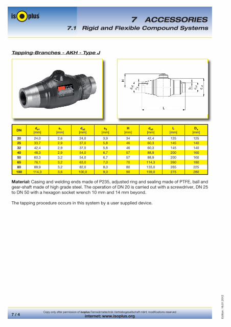
Tapping-Branches - AKH - Type J
DNda1
[mm]s1
[mm]da2
[mm]s2
[mm]H
[mm]da3
[mm]L
[mm]Da
[mm]
20 24,0 2,6 24,0 3,9 34 42,4 125 12525 33,7 2,9 37,0 5,8 46 60,3 145 14032 42,4 2,9 37,0 5,8 46 60,3 145 14040 48,3 2,9 54,0 6,7 57 88,9 200 16050 60,3 3,2 54,0 6,7 57 88,9 200 16065 76,1 3,2 63,0 7,0 70 114,3 260 18080 88,9 3,2 82,0 8,0 80 133,0 265 225100 114,3 3,6 100,0 9,0 90 159,0 275 280
Material: Casing and welding ends made of P235, adjusted ring and sealing made of PTFE, ball and gear-shaft made of high grade steel. The operation of DN 20 is carried out with a screwdriver, DN 25 to DN 50 with a hexagon socket wrench 10 mm and 14 mm beyond.
The tapping procedure occurs in this system by a user supplied device.
7.1 Rigid and Flexible Compound Systems

Copy only after permission of isoplus Fernwärmetechnik Vertriebsgesellschaft mbH; modifications reserved
internet: www.isoplus.org 7 / 5
Ed
ition
: 16.
01.2
012
7.1.3 One-Time-Ball-Valve
One-time- respectively connection ball valves will be used for the end of a construction-section, which will be continued later on. As the end-piece will be welded at the pipe end, the existing isoplus-pipeline may be continued at any time, without draining the pipes and without interruption of pipeline operation.
One-time-ball-valves will be welded in closed position into the pipeline, like a piece of pipe. In case of double pipes it has to be considered that the assembling of the ball valves should be made clockwise and longitudinal transposed.
For protection reasons and in order to avoid that PUR-foam will enter into the open end of the ball valve, the assembling of a torospherical head respectively a pipe cap acc. to DIN EN 10253-2 will be prescribed. Post insulation will be carried out by use of an end-coupler.
Material: Casing and welding ends made of P235, adjusted ring and sealing made of PTFE, ball and gear-shaft made of high grade steel. If the continuing section will be installed, assembled and welded on to the one-time-ball-valve, the line will be put in operation. For that the locking-screw of the one-time-ball-valve will be moved by use of a screw driver respectively an inside-hexagon-key and will be welded afterwards. The post insulation ensues with a double reducing joint.
One-Time-Ball-Valves - Maximum dimensions of available types
DNda
[mm]H
[mm]h
[mm]L
[mm]
Da
Single pipe[mm]
Double Pipe[mm]
20 26,9 57,2 36,0 230 110 14025 33,7 75,2 45,0 235 125 18032 42,4 91,5 56,5 260 140 20040 48,3 100,1 62,0 260 160 22550 60,3 121,0 76,5 300 180 28065 76,1 144,7 87,5 360 200 31580 88,9 171,4 101,5 370 225 355100 114,3 210,9 122,0 390 280 450125 139,7 236,9 140,0 325 315 500150 168,3 269,6 160,0 350 355 560200 219,1 321,5 185,0 390 400 670
7 ACCESSORIES7.1 Rigid and Flexible Compound Systems

Copy only after permission of isoplus Fernwärmetechnik Vertriebsgesellschaft mbH; modifications reserved
internet: www.isoplus.org7 / 6
Ed
ition
: 16.
01.2
012
7.1.4 End Cap
Simplex-End Cap Duplex-End Cap Zipper-End Cap
End caps are suitable for gable-end protection against water in order to avoid moisture penetration into the PUR-foam at the pipe ends, in buildings or constructions. Inside of manholes the end caps have to be secured against flooding with heating water.
Additionally end caps will protect against diffusion of PUR-foam-cell-gas which will occur at the open pipe ends. According to the result of long term investigations, cell-gas diffusions at not protected pipe ends respectively gable-ends, will influence the life time of PEHD jacket-pipes in a negative way. Therefore installation of pipe ends without end cap will be generally not permitted.
The pipe-layer will be responsible for putting on the end caps before connection to the continuing conventional pipe lines, inside of the building. End caps may be not cut open and have to be protected against heat and burnings in case of welding works. In order to guarantee a correct shrinking of the end caps, a minimum overlapping distance of the PEHD-jacket-pipe has to be considered inside of the building.
In case of medium temperatures > 120 °C end caps have to be fixed additionally at carrier pipe and jacket pipe by use of anti corrosion gripping tapes. End caps are available in all carrier-/jacket-pipe combinations. For double pipes so called Duplex-end caps are available and zipper-end caps for already welded pipes. If Simplex end caps are used for isoplus double pipes, an aging-resistant EDPM fill block to bridge the clear distance between the carrier pipes is included in delivery. This will be pressed into the gap before assembly.
7 ACCESSORIES
Assembling steps see chapter 10.2.12 Carrier-/Jacket-pipe combinations see chapter 2.2.2, 2.2.3, 2.3.2, 2.3.3, 3.2, 3.3, 3.4, 3.5
All end caps consist of a heat shrinking, molecular cross linked, modified and therefore nonweldable Polyolefin, and are coated by a special temperature resistant sealing adhesive at both ends. Resistant against weather conditions- and chemical influence as well as UV-radiation and alkaline soil.
7.1 Rigid and Flexible Compound Systems

Copy only after permission of isoplus Fernwärmetechnik Vertriebsgesellschaft mbH; modifications reserved
internet: www.isoplus.org 7 / 7
Ed
ition
: 16.
01.2
012
7.1.5 Wall duct
Sealing Ring Standard Sealing Insert with Pipe Liner
Sealing rings resp. -inserts are used in order to avoid water entry at wall ducts inside of buildings or manholes. The pipe-layer will be responsible for putting on the sealing rings and for centering the inserts at the wall ducts before the connection to the pipeline of the building.
The wall ducts have to be installed rectangular to the wall. Radial loads due to subsidences at building- or manhole entry as well as lateral dislocations will cause leakages. This can be avoided by careful compression of the soil at the area of the entry. Installation of isoplus-pipes without sealing rings is not permitted. Inside of the building a minimum overlapping of the PE-jacket-pipe has to be considered.
Sealing Ring - Standard
Standard sealing ring consists of special profiled, non ageing neoprene rubber ring and is suitable for sealing against non pressing and none damming up water acc. to DIN 18195-4. The ring-breadth is 50 mm independing from nominal diameter, the strength resp. thickness of the conical ring is 12 mm up to 22 mm. The ring will be pushed to the middle of the wall duct and will be imbedded in concrete afterwards by a constructing company. At standard sealing rings axial expansions up to 10 mm are permissible.
Sealing Insert - C 40
In case of pressing and damming up water acc. to DIN 18195-6 gas- and compressed water a tight sealing insert, which can be restreched from inside has to be used. This consists of a double-sealing insert with two steel-pressure-disks, as well as each of two 40 mm, black EPDM-solid-rubber sealings (Ethylen-Propylen-Rubber), shore-hardness = 35 ShA. All metal parts are electrogalvanized, yellow-chromated and sealed. The special for KMR constructed sealing areas will guarantee a constant distribution of compression on the PEHD-jacket-pipe and will avoid any imprints or necks.
It will be installed into a pipe liner or core drilling. Drilling resp. imbedding in concrete of the pipe liner will be carried out by a construction company. The length of the pipe liner is depending from the wall thickness. The retention moments of the screws have to be considered strictly, in order to avoid any damages of the jacket-pipe during assembling. At sealing inserts axial expansions up to 20 mm are permissible in case of creeping expansion, that means no temperature-impacts which will occur i. e. at steam.
Assembling steps see chapter 10.2.13 and chapter 10.2.14Carrier- /Jacket-pipe combinations see chapter 2.2.2, 2.2.3, 2.3.2, 2.3.3, 3.2, 3.3, 3.4, 3.5
7 ACCESSORIES7.1 Rigid and Flexible Compound Systems

Copy only after permission of isoplus Fernwärmetechnik Vertriebsgesellschaft mbH; modifications reserved
internet: www.isoplus.org7 / 8
Ed
ition
: 16.
01.2
012
7.1.6 Expansion Pads
Expansion pads (DP) are compensating movements of isoplus-pipelines at L-, Z- and U-elbows, at branches, at reduction- and end-couplers, at shut-off-valves as well as at high- and lowest points. The pipe-layer is responsible to keep the increased minimum distances between the jacket-pipes and the trench side-walls at the expansion pad areas, see chapter 9.2.4.
Only because of that a regular DP-assembling according to the pipe-static requirements will be guaranteed. As standard DP with a thickness of 40 mm and a length of 1000 mm will be produced. If a thickness of > 40 mm will be required, two or more pads should be glued upon another by flaming up. Assembling will be made exclusively by approved and isoplus-educated installers.
Kind of execution
DP - Standard
One meter of DP-standard includes two pieces of stripes for lateral assembling at 3.00 o’clock and 9.00 o’clock-position. Hereby a heat accumulation will arise at the pipe-peak.
DP - Part-Covering
Like DP-standard, but with an additional factory backed outside, solid edge-area of laminate for complete covering of the PEHD-jacket-pipe in closed horizontal-oval execution. Hereby no heat accumulation will arise and penetration of sand between jacket-pipe and pad will be avoided.
DP - Full-Covering
Like DP-part-covering, but not in stripe-execution, however as DP-mats, which will cover the circumference of the PE-jacket-pipes totally. Longitudinal and lateral abutting ends will be glued by flaming up of laminate. One meter DP-full covering consists of a piece of mat of 1000 mm length and a breadth depending from dimension. This alternative can be used only conditionally, resp. the DP-thickness has to be reduced to max. 80 mm, due to the high heat accumulation, especially at the pipe-peak.
7 ACCESSORIES7.1 Rigid and Flexible Compound Systems
Copy only after permission of isoplus Fernwärmetechnik Vertriebsgesellschaft mbH; modifications reserved
internet: www.isoplus.org 7 / 9
Ed
ition
: 16.
01.2
012
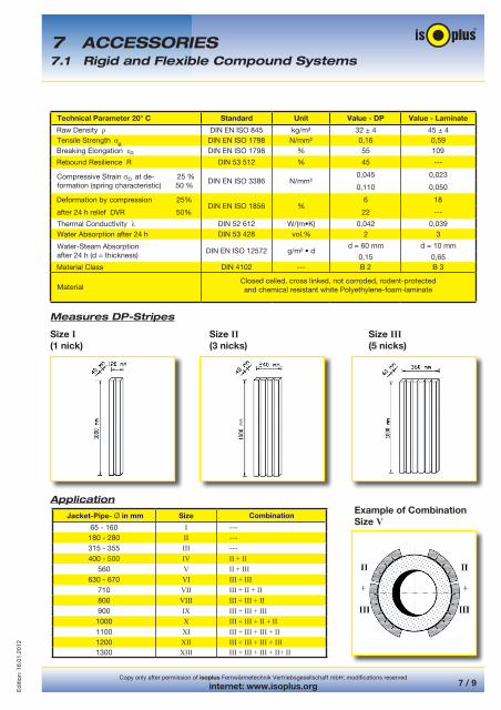
Technical Parameter 20° C Standard Unit Value - DP Value - Laminate
MaterialClosed celled, cross linked, not corroded, rodent-protectedand chemical resistant white Polyethylene-foam-laminate
Measures DP-Stripes
Size I Size II Size III(1 nick) (3 nicks) (5 nicks)
ApplicationExample of CombinationSize V
Jacket-Pipe- Ø in mm Size Combination
65 - 160 I ---180 - 280 II ---315 - 355 III ---400 - 500 IV II + II
560 V II + III630 - 670 VI III + III
710 VII III + II + II800 VIII III + III + II900 IX III + III + III1000 X III + III + II + II1100 XI III + III + III + II1200 XII III + III + III + III1300 XIII III + III + III + II+ II
7 ACCESSORIES7.1 Rigid and Flexible Compound Systems
Copy only after permission of isoplus Fernwärmetechnik Vertriebsgesellschaft mbH; modifications reserved
internet: www.isoplus.org7 / 10
Ed
ition
: 16.
01.2
012
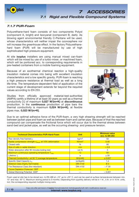
7.1.7 PUR-Foam
Polyurethane-hard foam consists of two components Polyol (component A, bright) and Isocyanat (component B, dark). As blowing agent environmental friendly C-Pentane will be used, whose characteristics will neither impair the ozonosphere nor will increase the greenhouse effect. In the factory Polyurethane-hard foam (PUR) will be manufactured by use of high sophisticated high pressure equipment.
At site isoplus installers are using manual mixed can-foam which will be mixed by use of a turbo-mixer, or machined foam, which will be portioned acc. to corresponding requirements in pre-heated containers from a mobile foaming equipment.
Because of an exothermal chemical reaction a high-quality insulation material comes into being with excellent insulation characteristics and a low specific gravity. PUR-foam is reaching a high pressure resistance at thermal load as well as a long life-time. The temperature-dependent field of application of the current stage of development extends far beyond the required values according to EN 253.
Studies from officially approved material-test-authorities (AMPA) certify a lifetime of at least 30 years as well as a thermal conductivity [ ] of maximum 0,027 W/(m•K) at discontinuous production. In the continuous production of pipe bars the thermal conductivity is maximum 0,024 W/(m•K), at flexible pipes max. 0,023 W/(m•K).
Technical Characteristics PUR-Hard-Foam UnitMinimum valueacc. to EN 253
Raw density free foamed kg/m3 50Radial compression strength Druck at 10% deformation N/mm2 0,40Closed cells % 90Size of cells in radial direction mm < 0,5Water absorption after 90 minutes boiling-test vol.% 5Maximum continuous operating temperature Tmax °C 161Lifetime L a ≥ 30Thermal Conductivity at 50 °C average temperature W/(m•K) ≤ 0,027Specific Heat Capacity cm kJ/(kg•K) 1,4Material Class (highly flammable) DIN 4102 B 3Fire Resistance Class (fire-retardant) DIN 4102 < F 30Ozone Depletion Potenzial ODP --- 0Global Warming Potential GWP --- < 0,001
7 ACCESSORIES
Foam used at site has to be stored acc. to EN 489 at +15° up to +25° C, and can be used at surface temperatures between min. 15° and max. 45° C. Maximum storing period is 3 months. Depending from quantity delivery will be in 1 ltr., 5 ltr. or in 10 ltr. units, incl. the corresponding required multiple mixing-cans.
Due to an optimal adhesive force of the PUR-foam, a very high shearing strength will be reached between jacket-pipe and foam as well as between foam and carrier pipe. Because of that the reached compound can compensate the frictional force which will occur due to the thermal stress between sand-bed and jacket-pipe, as well as the occurring shearing- and pressure tension.
7.1 Rigid and Flexible Compound Systems
Copy only after permission of isoplus Fernwärmetechnik Vertriebsgesellschaft mbH; modifications reserved
internet: www.isoplus.org 7 / 11
Ed
ition
: 16.
01.2
012
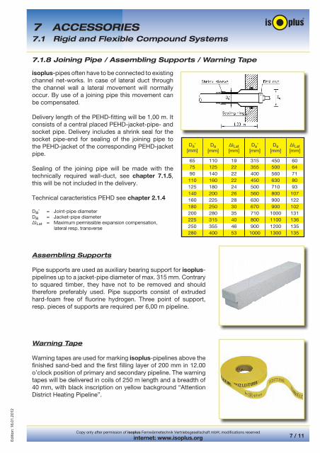
7.1.8 Joining Pipe / Assembling Supports / Warning Tape
Assembling Supports
Pipe supports are used as auxiliary bearing support for isoplus-pipelines up to a jacket-pipe diameter of max. 315 mm. Contrary to squared timber, they have not to be removed and should therefore preferably used. Pipe supports consist of extruded hard-foam free of fluorine hydrogen. Three point of support, resp. pieces of supports are required per 6,00 m pipeline.
Warning Tape
Warning tapes are used for marking isoplus-pipelines above the finished sand-bed and the first filling layer of 200 mm in 12.00 o’clock position of primary and secondary pipeline. The warning tapes will be delivered in coils of 250 m length and a breadth of 40 mm, with black inscription on yellow background “Attention District Heating Pipeline”.
isoplus-pipes often have to be connected to existing channel net-works. In case of lateral duct through the channel wall a lateral movement will normally occur. By use of a joining pipe this movement can be compensated.
Delivery length of the PEHD-fitting will be 1,00 m. It consists of a central placed PEHD-jacket-pipe- and socket pipe. Delivery includes a shrink seal for the socket pipe-end for sealing of the joining pipe to the PEHD-jacket of the corresponding PEHD-jacket pipe.
Sealing of the joining pipe will be made with the technically required wall-duct, see chapter 7.1.5, this will be not included in the delivery.
Technical caracteristics PEHD see chapter 2.1.4
Da, = Joint-pipe diameter
Da = Jacket-pipe diameterΔlLat = Maximum permissible expansion compensation, lateral resp. transverse
Da,
[mm]Da
[mm]ΔlLat [mm]
Da,
[mm]Da
[mm]ΔlLat[mm]
65 110 19 315 450 6075 125 22 355 500 6490 140 22 400 560 71
110 160 22 450 630 80125 180 24 500 710 93140 200 26 560 800 107160 225 28 630 900 122180 250 30 670 900 102200 280 35 710 1000 131225 315 40 800 1100 136250 355 46 900 1200 135280 400 53 1000 1300 135
7 ACCESSORIES7.1 Rigid and Flexible Compound Systems

Copy only after permission of isoplus Fernwärmetechnik Vertriebsgesellschaft mbH; modifications reserved
internet: www.isoplus.org7 / 12
Ed
ition
: 16.
01.2
012
7.2.1 Press Tool / Bending Tool
Press Tool
For the pressing procedure three types of tools are available:
Mechanical press tool for isopex-pipes up to dimension of 40 mm
Hydraulically press tool for isopex-pipes up to dimension of 40 mm
Hydraulically press tool for isopex-pipes starting from 50 mm
All tools incl. all required accessories like press-pincers, -blocks and -ridges, expansion pincer and -heads as well as the corresponding small accessories are completed in a stable metal suitcase.
Depending from requirements they can be used for some days or weeks against payment. During this time the user of the tools will be exclusively responsible for correct function, cleaning and complete return of the equipment.
Bending Tool
For the procedure of bending of isoflex or/and isocu the hydraulically isoplus-bending tool incl. pump and pressure hoses will be available. Bending will be made in three to four steps. Depending from kind of flexible pipe different minimum bending radius should be considered. See chapter 3.2.2 and chapter 3.3.2
The use of a not suitable bending equipment is not allowed. In order to avoid damages of the flexible pipes bending around edges like foreign pipe-lines, squared timber, buildings- or wall-corners are not permitted. Depending from requirement the equipment may be used for days or weeks. During this period the user will be exclusively responsible for correct function, cleaning and the complete return of all parts.
For bending of isopex-pipes the use of a tool will be not possible, due to the high self-elasticity of the carrier pipe.
7.2 Special Accessories Flexible Compound Systems7 ACCESSORIES

Copy only after permission of isoplus Fernwärmetechnik Vertriebsgesellschaft mbH; modifications reserved
internet: www.isoplus.org 7 / 13
Ed
ition
: 16.
01.2
012
7.2.2 Protection Cap / Distributing Manhole
Protection Cap
In order to protect the PUR foam against moisture by means of condense, inside of buildings (drying-rooms) protection caps should be used. These are consisting of age-resistant neoprene-rubber and will be used as simplex- or duplex-cap, depending from kind of flexible pipe-type.
The pipe laying company will be responsible to put on the protection cap before connecting with the building line. These caps have to be protected from fire, may not be cutted and may not be used for post installation. The installation of the pipe ends without protection cap is not permitted.
Available PE-jacket-pipe dimensions see chapter 3.2.2, 3.3.2, 3.4.2, 3.5.2
Distributing Manhole
A distributing manhole will be used for checking of installations like branches within a isopex-pipeline. This inspection manhole incl. cover-plate consists of polyethylene (PE) and will be delivered in dimension of 800 mm and an installation height respectively depth of approx. 700 mm.
The universal and water-tight construction allows the connection of up to eight pipes with jacket-pipe dimensions of 65 to 180 mm.
Before the flexible pipe will be installed, the pipe layer should install the corresponding sealing set. This consists of a closed heat shrinkable sleeve as well as of a centre ring in accordance with the jacket-pipe dimension. The sealing sets are not part of the delivery of the distributing manhole.
At a pipe covering height of 0,4 m the maximum admissible load of the cover will be 50 kN/m². In case that higher coverings will be reached, a well ring respectively a soak-hole concrete ring should be installed above the PE-manhole.
7 ACCESSORIES7.2 Special Accessories Flexible Compound Systems

Copy only after permission of isoplus Fernwärmetechnik Vertriebsgesellschaft mbH; modifications reserved
internet: www.isoplus.org7 / 14
Ed
ition
: 16.
01.2
012
7.2.3 Twin-Accoutrement
This fitting unit, consisting of two ball-valves, may be used for all isoplus-flexible pipes for heating installations. It should be installed at the wall in closed position with the included mounting-plate.
Casing and welding ends are made of P235GH , (Material-Number 1.0345), ball of stainless steel (Material-Number 1.4301) and gear-shaft of stainless steel (Material-Number 1.4404), ring and sealing of PTFE (Teflon), available for carrier pipe dimensions of ¾” to maximum 2”.
For isopex type H-25 to H-63 additionally two connection couplings with welding ends are required, see chapter 3.6.5.
7 ACCESSORIES7.2 Special Accessories Flexible Compound Systems


![DOPPELROHR - HSH-Installatör...isoplus nach AGFW FW 401. Die angegebenen Stahlwandstärken entsprechen den Standardwanddicken bei isoplus, generell sind diese gegen Innendruck [p]](https://img.dokumen.tips/doc/110x75/60c49f5c0b8ae57b2d200984/doppelrohr-hsh-installatr-isoplus-nach-agfw-fw-401-die-angegebenen-stahlwandstrken.jpg)