Embed Size (px)
Citation preview
3D Analysis and Design of a multi storey building
10
Fig2.Working plan
1.2Project statement:
3D Analysis and Design of a multi storey building
11
Salient features:
Utility of the building: Residential complex
Shape of building : Apartments
Number of storeys: G+4
Type of construction : R.C.C Framed Structure
Type of walls : Brick wall
Geometric details:
Ground floor height : 3.5m
Floor to floor height : 3.5m
Height of plinth : 1.5m
Depth of foundation : 20cm
Materials:
Concrete grade : M25
All steel grades : Fe415
Bearing capacity of soil:20ton/m^2
1.3 STAAD. Pro:
• STAAD is the powerful design software licensed by Bentley. STAAD stands for
Structural Analysis and Design
• STAAD is comprehensive structural engineering software that addresses all aspects of
structural engineering as analysis, design, verification, and visualization.
3D Analysis and Design of a multi storey building
12
• STAAD performs the analysis and design of the structure for different types of
structures, such as trusses, plane and space.
• STAAD has ability to perform design of members following more than 20
international building codes
• Alternatives for STAAD:
Struts,robot,sap,adds pro gives details very clearly regarding reinforcement and
manual calculations. But these software‘s are restricted to some designs only whereas
staad can deal with several types of structures.
• Limitations of the STAAD:
1. Huge output data
2. Even analysis of a small beam creates large output data
3. Unable to show plinth beams.
1.4 Excel:
Microsoft Excel is a spreadsheet tool capable of performing calculations, analyzing
data and integrating information from different programs. Microsoft Excel is comprised of
organizational units called workbooks. A standard workbook contains worksheets and chart
sheets. Worksheets perform calculations, store and organize data, present graphics and
controls like a web page; they are extremely versatile. A worksheet in turn is comprised of
millions of cells. The job of a cell is to store a formula that performs a calculation or
communicates with some other application (i.e. program) such as a database. They also store
and present data. A chart sheet's job is to present a chart or graph developed from data stored
on a worksheet.
IMPORTANCE OF HAND CALCULATIONS
The students have been asked to perform hand calculations. Computer analysis
and
design programs offer great benefits to the design engineer. However, the computer
programscan be easily misused without proper precautions in analysis and design procedures. If the design of any structure is based on the results obtained from erroneous computer analysis, it can lead to structural failures, costly disputes and poor performing structures. Performing the following procedures can eliminate many of the errors.
1. Model the structure as closely to the real structure as possible.
2. Recognize the important structural reactions
3D Analysis and Design of a multi storey building
13
3. Check the input and understand the material behaviour and boundary conditions 4. Perform simple equilibrium and compatibility checks using hand calculations.
5. Know and understand the limitations of the software.
A series of hand design calculations were performed on a typical slab panel, a
randomly
selected set of three beams and columns, one critical footing supporting the
highest column load in the structure, and a typical combined footing. The purpose of the hand design calculation was to verify manually, the analysis from the STAAD software package, and the Indian code driven RC Design Suite programs.
2. STRUCTURAL PLANNING
2.1. Introduction:
Engineering is a professional art of applying science to the efficient conversion of natural
resources for the benefit of the mankind. Engineering, therefore, requires above all creative
imagination to innovate useful application for natural phenomenon.
The entire process of structural planning and design requires not only imagination and
conceptual thinking but also sound knowledge of science of structural engineering besides
knowledge of practical aspects, such as recent design codes and bye laws, backed up by
ample experience, intuition and judgment. It may be clarified that Code of practice, which is
commendable of good practices drawn up by good experienced engineers, should never be
allowed to replace the conscience and competence of the engineer. The purpose of standards
is to ensure and enhance the safety, keeping careful balance between economy and safety.
The process of design commences with planning of the structure, primarily to meet its
functional requirements. Initially, the requirements proposed by the client are taken into
consideration. They may be vague, ambitious or even unacceptable from engineering point of
view because he is not aware of the various implications involved in the process of planning
and design, and about the limitations and intricacies of the structural science.
It is emphasized that any structure to be constructed must satisfy the need efficiently for
which it is intended and shall be durable for its desired life span.
3D Analysis and Design of a multi storey building
14
2.2. Structural Planning:
After getting an architectural plan of the buildings, the structural planning of the building
frame is done. This involves determination of the following:
(a) Positioning and orientation of columns.
(b) Positioning of beams
(c) Spanning of slabs
(d) Layout of stairs
(e) Selecting proper type of footing
The basic principle in deciding the layout of component members is that the loads should be
transferred to the foundation along the shortest path.
2.2.1. Positioning and orientation of columns :
Following are some guiding principles which help in deciding the column positions.
• Columns should preferably be located at or near the corners of the building and at the
intersections of the beams/walls.
• Since the basic function of the columns is to support beams which are normally
placed under the walls to support them, their position automatically gets fixed. The
commercial buildings have normally rectangular pattern of grid type but especially for
residential buildings.The said type of pattern for columns does not become possible.
• Select the position of column so as to reduce the bending moments in beams, when
the location of two columns are very near then one column should be provided instead
of two at such a position so as to reduce beam moment.
• Under certain rare circumstances to satisfy the functional requirements, it may not be
possible to provide upper storey columns above the columns at the parking level.
Then the column at parking level is required to support the eccentric columns at the
upper storeys. In such a case the column S at parking level is splayed or provided with
a bracket to support the columns at the upper storey. However, the column at parking
level will be subjected to heavy concentrated loads transferred from the columns of
the upper storeys.
Avoid larger spans of beams.
3D Analysis and Design of a multi storey building
15
• When the centre to centre distance between intersections of walls is large or where
there are no cross walls, the spacing between two columns is governed by limitations
on spans of supported beams, because spacing of columns decides the span of the
beam. As the span of the beam increases, the required depth of the beam, and its self
weight, and total load on beam increases. It is well known that the moment governing
the beam design varies with the square of the span and directly with the load. Hence
with the increase in span, there is considerable increase in the size of the beam.
• On the other hand, in the case of column, the increase in total load due to increase in
length is negligible as long as the column is short. Therefore the cost of the beam per
unit length increases rapidly with the span as compared to that of column. Columns
are, therefore in general, always cheaper compared to beams on the basis of unit cost.
Therefore, large spans of beams should preferably be avoided for economy reasons. In
general, the maximum spans of beams carrying live loads up to 4 KN/m2 may be
limited to following values.
Avoid large centre to centre distance between columns.
• Larger spacing of columns not only increases the span and the cost of beams but it
increases the load on the column at each floor posing problem of stocky columns in
lower storey of a multi-storey building. Heavy sections of column lead to offsets from
walls and obstruct the floor area.
Columns on property line
The columns on property line need special treatment. Since column footing requires certain
area beyond the column, difficulties are encountered in providing footing for such columns.
In such cases, the column may be shifted inside along a cross wall to make room for
accommodating the footing within the property line. Brackets may be taken out from the
column in continuation of cross beams to support walls along the boundary line.
Alternatively, a combined footing or a strap footing may be provided.
Orientation of columns:
• Avoid projection of column outside wall.
• According to requirements of aesthetics and utility, projections of columns outside the
wall in the room should be avoided as they not only give bad appearance but also
obstruct the use of floor space, and create problems in placing furniture flush with the
wall.
3D Analysis and Design of a multi storey building
16
• Provide depth of the column in the plane of the wall to avoid offsets. The problem of
projection of column normally occurs in the internal walls sincethey are usually
thinner. Now-a-days 150 mm thick walls are provided to get more floor space. This
has posed problem for external walls too, because the width of wall is required to be
kept not less than 200 mm to be to prevent column from being slender.
• Use L shaped columns at the corners or T shaped corners at the intersection of
intermediate cross walls. Alternatively spacing of the columns should be considerably
reduced so that the load on column at each floor is less and the necessity of large
sections for columns does not arise.
• Orient the column so that the depth of the column is contained in the major plane of
bending.
Bearing in mind the guiding points given above, the principles governing orientation of
columns given below can easily understood.
• When a column is rigidly connected to beams at right angles it is subjected to
moments in addition to the axial load. In such cases column should be oriented that
the depth of the column is perpendicular to major axis of bending so as to get larger
moment of inertia and hence greater moment resisting capacity it will also reduce
Leff/D ratio resulting in increase in the load carrying capacity of the column.
• It should be born in mind that increasing depth in the plane of bending not only
increase the moment carrying capacity but also increases its stiffness, thereby more
moment is transferred to the column at the beam column junction.
However, if the difference in bending moment in two mutually perpendicular
directions is not large as the depth of the column has sufficient strength in the plane of large
moment. This will avoid offsets inside the rooms.
2.2.2. Positioning of beams :
Following are some of the guiding principles for positioning of beams.
• Beams, shall, normally be provided under the walls to avoid the loads directly coming
on slabs.
• Since beams are primarily provided to support slabs, its spacing shall be decided by
the maximum spans of slabs. Slab requires the maximum volume of concrete to carry
a given load. Therefore the thickness of the slab is required to be kept minimum. The
3D Analysis and Design of a multi storey building
17
maximum practical thickness for residential/office/public buildings is 200 mm and
minimum is 100 mm.
• Avoid maximum spacing of beams from deflection and cracking criteria.
• It is well known that the deflection varies directly with the cube of the span and
inversely proportional with the cube of depth i.e. L3/D3. Hence larger span may be
avoided
• However for larger spans, normally higher L/D ratio is taken to restrict the depth from
considerations of headroom, aesthetics and psychological effect. Therefore spans of
beams which require the depth of beam greater than one meter should as far as
possible be avoided.
2.2.3. Spanning of slabs:
• When the rectangular slab is supported at its four edges, it acts as one way slab when
(ly/lx)>2 and two way slab for (ly/lx) <2. However the two way action of slab not only
depends on the aspect ratio (ly/lx) but also on ratio of reinforcement in the two
directions.
• A slab with (ly/lx)>2 is designed as one way, since in that case one way action is
predominant. In one way slab, main steel is provided along the short span only and
load is transferred to two opposite supports only. The steel along the long span just act
as distribution steel and is not designed for transferring the load but to distribute the
load.
• A two way slab having aspect ratio (ly/lx) <2 is general economical compared to one
way slab because steel long both the spans acts as main steel and transfer the load to
all its four supports.
• The two way action is advantageous essentially for large spans and for live loads
greater than 3 KN/m2. For short spans and light loads, steel required for two way slab
3D Analysis and Design of a multi storey building
18
does not differ appreciably as compared to steel for one way slab because of the
requirement of the minimum steel.
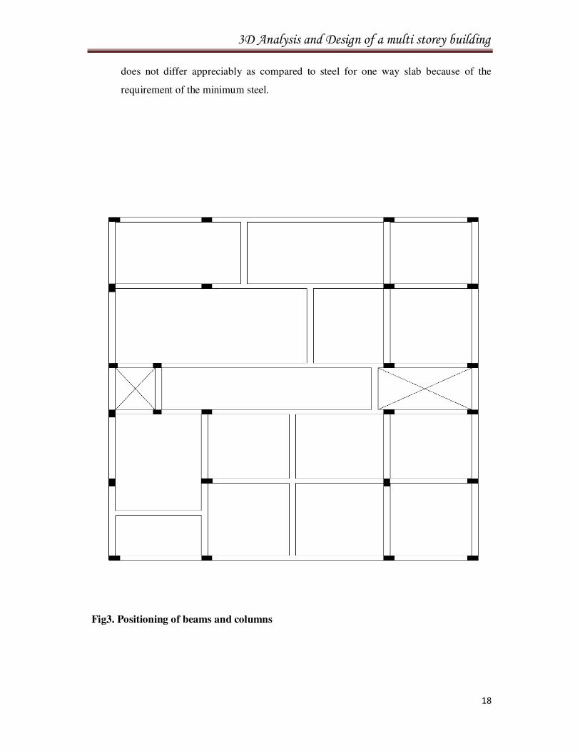
Fig3. Positioning of beams and columns
3D Analysis and Design of a multi storey building
19
2.2.4 Layout of stairs:
Initially it is necessary to know the different parts of stairs and guide lines for fixing their
dimensions. The guidelines for fixing dimensions of the component parts of stairs are as
under:
• The rise R should not be more than 200 mm and tread T not less than 200 mm. For
residential buildings rise R lies between 150 mm to 180 mm and tread T between 220
mm to 250 mm. For public buildings rise R lies between 120 mm to 150 mm and
tread between 250 mm to 300 mm.
• The sum of tread plus twice the rise should be between 500 mm 650 mm.
The width of the stairs is dependent on its usage and shall be such as to avoid
overcrowding. For residential buildings the width of the stairs should be between 0.8
m to 1mfor public buildings width of the stairs should be between 1.8 m to 2 m
• The width of the landing should not be less than width of stairs.
• For comfortable ascend on stairs, the number of steps on each flight should not be
greater than 12.
• The pitch of the stair way should not be greater than 38 degrees.
• The head room measured vertically above any step or below mid landing shall not be
less than 2 m
• Avoid winders as far as possible.
The type stairs and its layout is governed by the available size of staircase room and the
positions of beams and columns along the boundary of the staircase.
2.2.4. Choice of footing type:
The type of footing depends upon the load carried by the column and bearing capacity of the
supporting soil.Even under small building the soil may vary from soft clay to hard morrum.
• For framed structures under study isolated column footings are normally preferred.
3D Analysis and Design of a multi storey building
20
• In case of soils with very low bearing capacities or if black cotton soil exists for great
depths pile foundations can be an appropriate choice.
• If columns are very closely spaced and bearing capacity of the soil is low, raft
foundation can be an alternative solution.
• For a column on the boundary line, a combined footing or a strap footing may be
provided
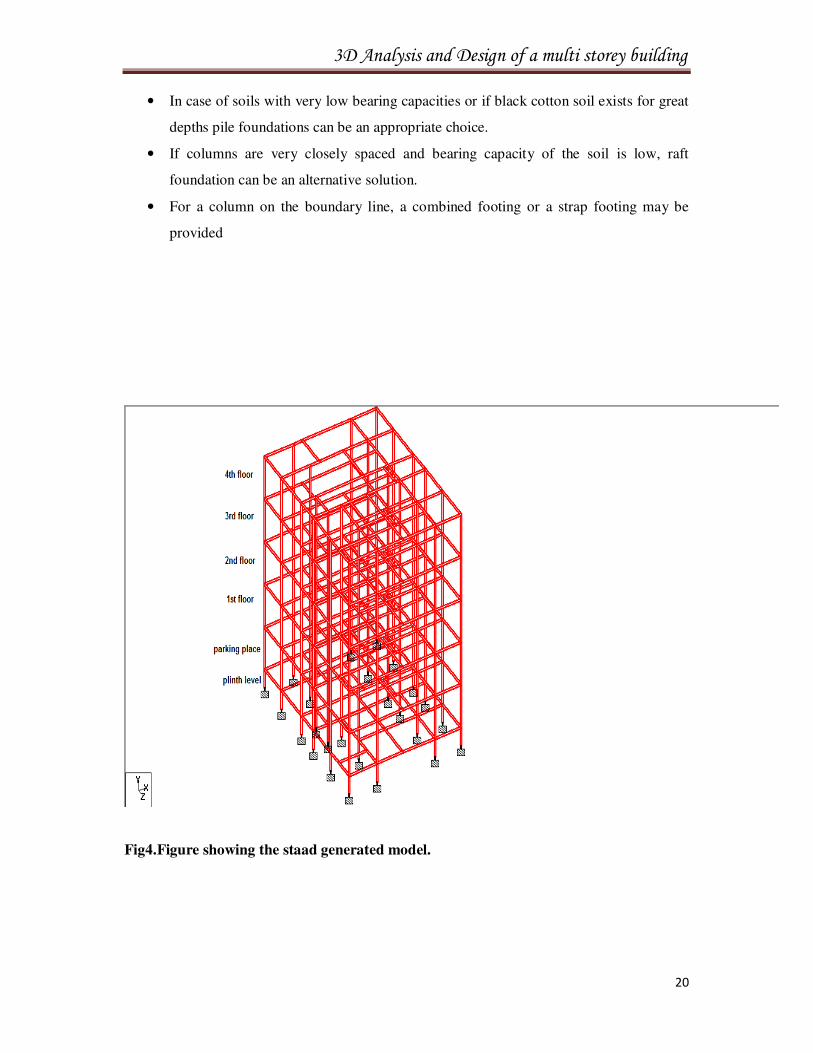
Fig4.Figure showing the staad generated model.
3D Analysis and Design of a multi storey building
21
3. ANALYSIS OF FRAMED STRUCTURE
3.1 Types of Loads :
The loads are broadly classified as vertical, horizontal and longitudinal loads. The vertical
loads consist of dead load, live load and impact load. The horizontal load comprises of wind
load and earthquake load. The longitudinal load (viz. Tractive and braking forces are
considered in special cases of design of bridges, design of gantry girder etc.)
3.1.1. Dead Load(DL):
Dead loads are permanent or stationary loads which are transferred structure throughout their
life span. Dead load is primarily due to self weight of structural members, permanent
partition walls, fixed permanent equipment and weights of different materials.
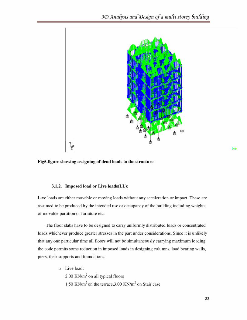
Dead load calculations:
o Dead load:
Slab weight: 0.120*25 = 3 KN/m2
Floor finishes: =1.50 KN/m2
Beams under external walls 0.230*3.13*20 =14.4KN/m
3D Analysis and Design of a multi storey building
22
Fig5.figure showing assigning of dead loads to the structure
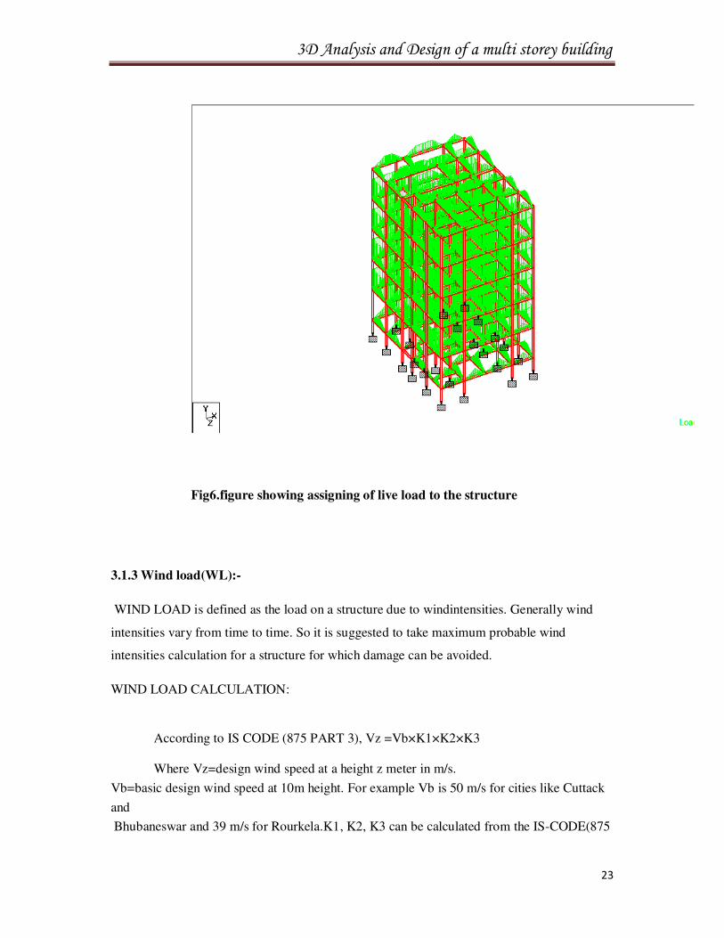
3.1.2. Imposed load or Live loads(LL):
Live loads are either movable or moving loads without any acceleration or impact. These are
assumed to be produced by the intended use or occupancy of the building including weights
of movable partition or furniture etc.
The floor slabs have to be designed to carry uniformly distributed loads or concentrated
loads whichever produce greater stresses in the part under considerations. Since it is unlikely
that any one particular time all floors will not be simultaneously carrying maximum loading,
the code permits some reduction in imposed loads in designing columns, load bearing walls,
piers, their supports and foundations.
o Live load:
2.00 KN/m2 on all typical floors
1.50 KN/m2 on the terrace,3.00 KN/m2 on Stair case
3D Analysis and Design of a multi storey building
23
Fig6.figure showing assigning of live load to the structure
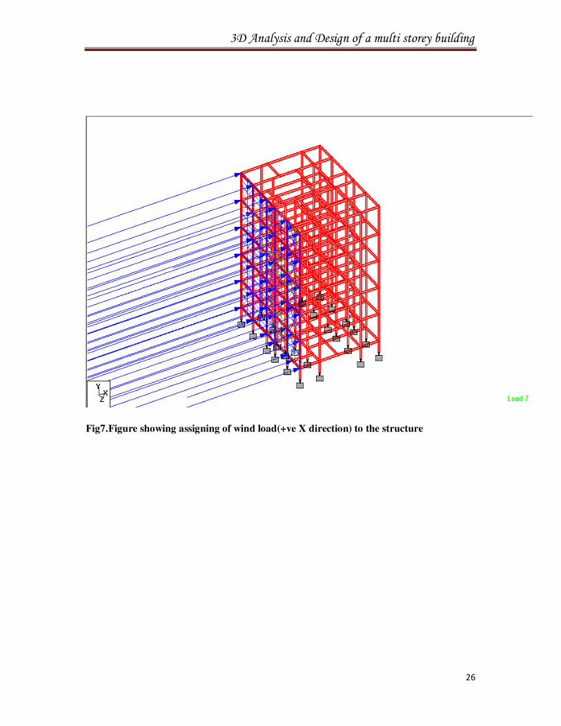
3.1.3 Wind load(WL):-
WIND LOAD is defined as the load on a structure due to windintensities. Generally wind
intensities vary from time to time. So it is suggested to take maximum probable wind
intensities calculation for a structure for which damage can be avoided.
WIND LOAD CALCULATION:
According to IS CODE (875 PART 3), Vz =Vb×K1×K2×K3
Where Vz=design wind speed at a height z meter in m/s.
Vb=basic design wind speed at 10m height. For example Vb is 50 m/s for cities like Cuttack
and
Bhubaneswar and 39 m/s for Rourkela.K1, K2, K3 can be calculated from the IS-CODE(875
3D Analysis and Design of a multi storey building
24
part3).
Pz=Design wind pressure at a height z meter.
Pz=0.6V z2
3.1.4 Seismic load (SL):
Seismic load can be calculated taking the view of acceleration response of the ground to the
super structure.
According to the severity of earthquake intensity they are divided into 4 zones.
1. Zone I and II are combined as zone II.
2. Zone III.
3. Zone IV.
4. Zone V.
SEISMIC LOAD CALCULATION:
According to the IS-CODE 1893(part 1) the horizontal Seismic coefficient Ah
for a
structure can be formulated by the following expression
Ah=ZISa/2RG
WHERE
Z=Zone factor depending upon the zone the structure belongs to.
For Zone II (z=0.1)
For Zone III (Z=0.16)
For Zone IV (Z=0.24)
For Zone V (Z=.36)
I=Importance factor.
For important building like hospital it is taken as 1.5 and other for other
building it is
taken as 1.
3D Analysis and Design of a multi storey building
25
R=Response reduction factor.
Sa/g=Average Response Acceleration coefficient.
However it should be notice that the ratio of I and R should not be greater
than 1.
Combination load case:1.5(DL+LL) As the design is for the limit state a
safety factor of 1.5 is considered.
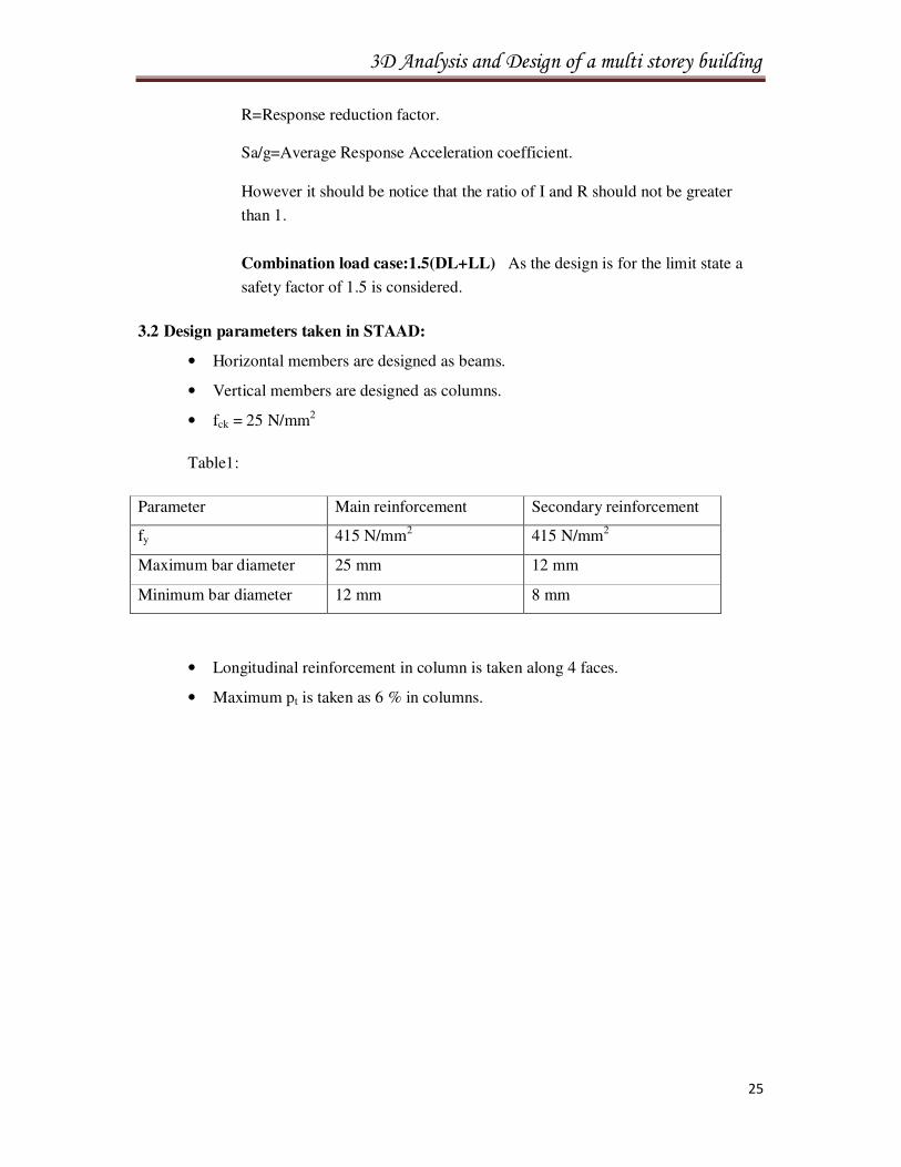
3.2 Design parameters taken in STAAD:
• Horizontal members are designed as beams.
• Vertical members are designed as columns.
• fck = 25 N/mm2
Table1:
Parameter Main reinforcement Secondary reinforcement
fy 415 N/mm2 415 N/mm2
Maximum bar diameter 25 mm 12 mm
Minimum bar diameter 12 mm 8 mm
• Longitudinal reinforcement in column is taken along 4 faces.
• Maximum pt is taken as 6 % in columns.
3D Analysis and Design of a multi storey building
26
Fig7.Figure showing assigning of wind load(+ve X direction) to the structure
3D Analysis and Design of a multi storey building
27
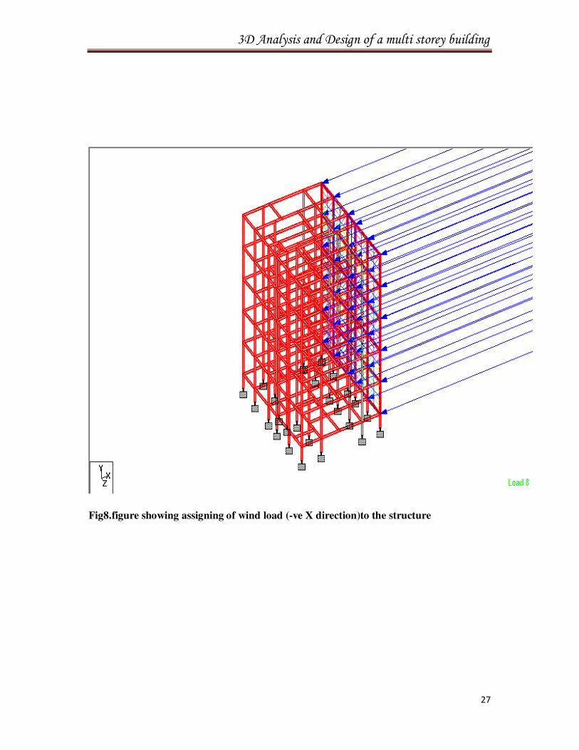
Fig8.figure showing assigning of wind load (-ve X direction)to the structure
3D Analysis and Design of a multi storey building
28
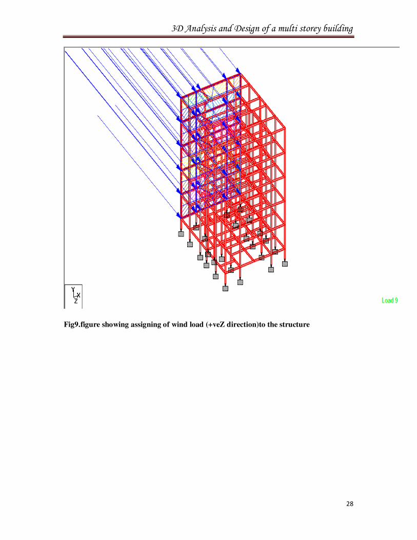
Fig9.figure showing assigning of wind load (+veZ direction)to the structure
3D Analysis and Design of a multi storey building
29
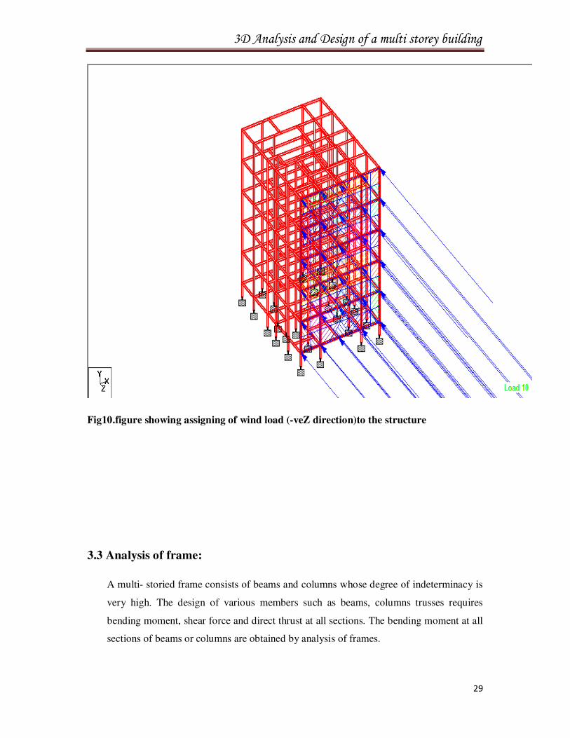
Fig10.figure showing assigning of wind load (-veZ direction)to the structure
3.3 Analysis of frame:
A multi- storied frame consists of beams and columns whose degree of indeterminacy is
very high. The design of various members such as beams, columns trusses requires
bending moment, shear force and direct thrust at all sections. The bending moment at all
sections of beams or columns are obtained by analysis of frames.

3D Analysis and Design of a multi storey building
30
Frames are analyzed for vertical and horizontal loads separately final moments are
obtained by super imposing.
Fig11.Deflection diagram
3D Analysis and Design of a multi storey building
31
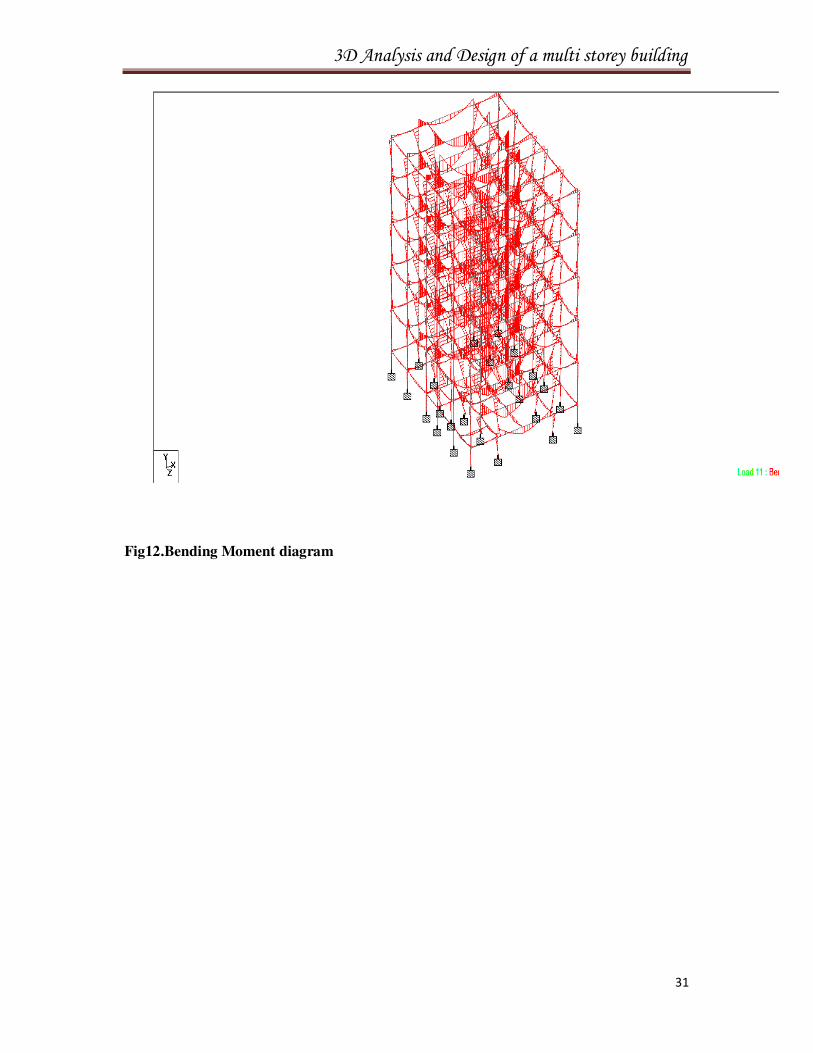
Fig12.Bending Moment diagram
3D Analysis and Design of a multi storey building
32
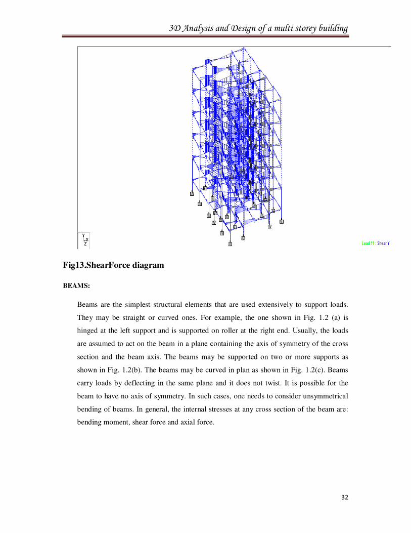
Fig13.ShearForce diagram
BEAMS:
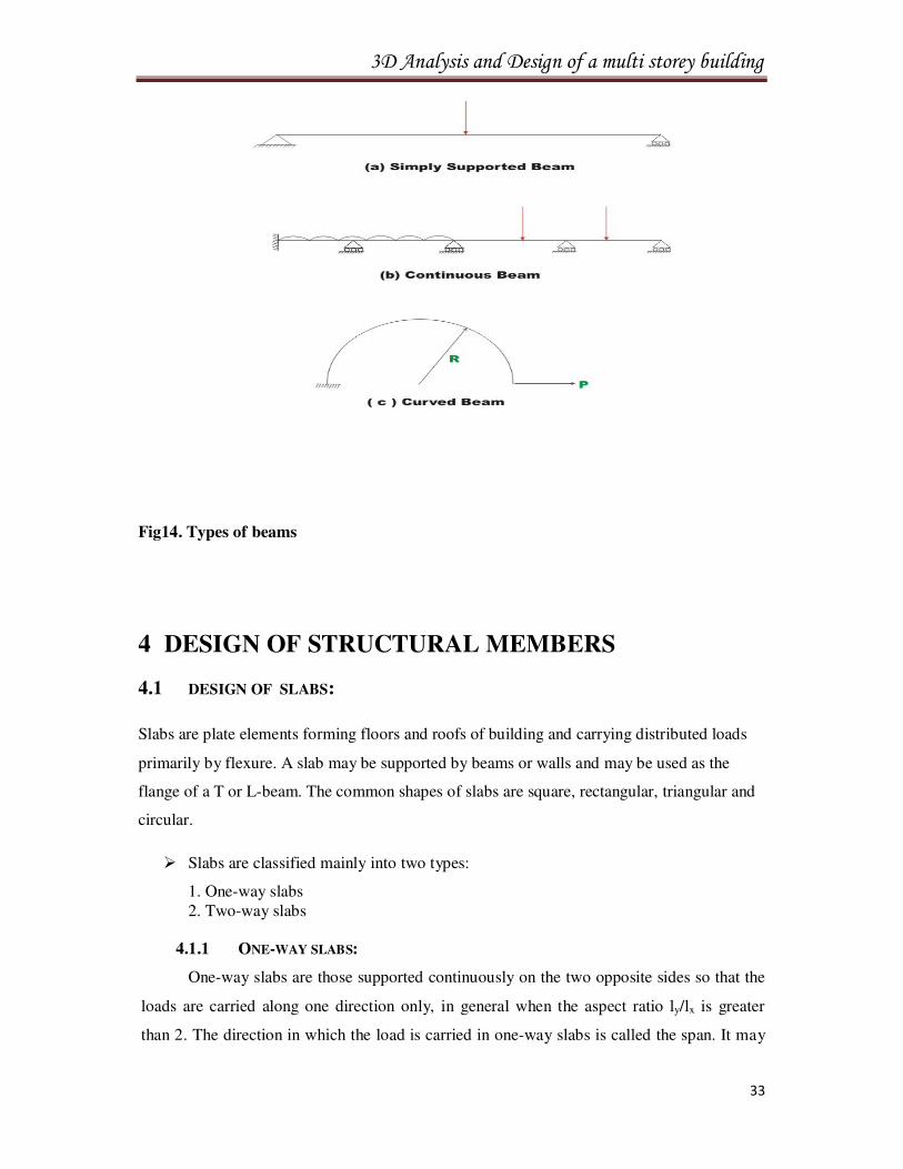
Beams are the simplest structural elements that are used extensively to support loads.
They may be straight or curved ones. For example, the one shown in Fig. 1.2 (a) is
hinged at the left support and is supported on roller at the right end. Usually, the loads
are assumed to act on the beam in a plane containing the axis of symmetry of the cross
section and the beam axis. The beams may be supported on two or more supports as
shown in Fig. 1.2(b). The beams may be curved in plan as shown in Fig. 1.2(c). Beams
carry loads by deflecting in the same plane and it does not twist. It is possible for the
beam to have no axis of symmetry. In such cases, one needs to consider unsymmetrical
bending of beams. In general, the internal stresses at any cross section of the beam are:
bending moment, shear force and axial force.
3D Analysis and Design of a multi storey building
33
Fig14. Types of beams
4 DESIGN OF STRUCTURAL MEMBERS
4.1 DESIGN OF SLABS:
Slabs are plate elements forming floors and roofs of building and carrying distributed loads
primarily by flexure. A slab may be supported by beams or walls and may be used as the
flange of a T or L-beam. The common shapes of slabs are square, rectangular, triangular and
circular.
� Slabs are classified mainly into two types:
1. One-way slabs 2. Two-way slabs
4.1.1 ONE-WAY SLABS:
One-way slabs are those supported continuously on the two opposite sides so that the
loads are carried along one direction only, in general when the aspect ratio ly/lx is greater
than 2. The direction in which the load is carried in one-way slabs is called the span. It may
3D Analysis and Design of a multi storey building
34
be in the long or short direction. One-way slabs are usually made to span in the shorter
direction since the corresponding bending moments and shear forces are the least. The main
reinforcements are provided in the span direction. Steel is also provided in the transverse
direction to distribute any unevenness that may occur in loading and for temperature and
shrinkage effects in that direction. The steel is called distribution steel or secondary
reinforcement. The main steel is calculated from the bending moment consideration and
under no circumstances should it be less than the minimum specified by the code. The
secondary reinforcement provided that, is usually the minimum specified by the code for
such reinforcement.
4.1.2 TWO-WAY SLABS :
Two-way slabs are those slabs that are supported continuously on all four sides and of
such dimensions that the loads are carried to the supports along both directions. In two-way
slabs, the slab is stiffened along both the directions by providing main steel reinforcement
along both the directions. In general slabs are designed as two-way slabs when the aspect
ratio (ly/lx)is less than 2. Generally two-way slabs are economical than one-way slabs.
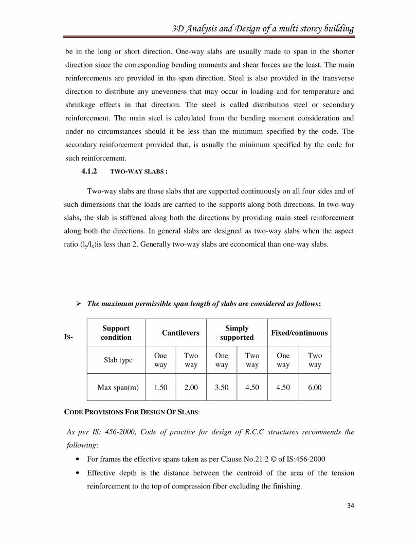
� The maximum permissible span length of slabs are considered as follows:
IS-
CODE PROVISIONS FOR DESIGN OF SLABS:
As per IS: 456-2000, Code of practice for design of R.C.C structures recommends the
following:
• For frames the effective spans taken as per Clause No.21.2 © of IS:456-2000
• Effective depth is the distance between the centroid of the area of the tension
reinforcement to the top of compression fiber excluding the finishing.
Support
condition Cantilevers
Simply
supported Fixed/continuous
Slab type One way
Two way
One way
Two way
One way
Two way
Max span(m) 1.50 2.00 3.50 4.50 4.50 6.00
3D Analysis and Design of a multi storey building
35
• When (Ly/Lx) is less than 2, the slab is designed as Two-way Slab, when (Ly/Lx) is
greater than 2, the slab is designed as One-way Slab, as per the coefficients given in
table 22 of IS:456-2000 torsion reinforcement need not be provided at any corner
contained by edges over both of which the slab is continuous.
• Maximum diameter of reinforcing bar shall not exceed the 1/8th of the total thickness
of slab (clause 25.2.2).
• Cover to reinforcement, at each end of reinforcing bar not less than 25mm or less than
twice the diameter of such bar (clause 25.4.1).
• Cover to reinforcement, for tensile, compressive shear or other reinforcement in slab,
not less than 20mm nor less than diameter of such bar.
• Maximum permissible spacing of distribution reinforcement shall not be more than 3
times of the effective depth of a slab or 30cm, whichever is smaller.
• Max permissible spacing of distribution reinforcement shall not be more the 5 times
effective depth of a slab or 45cms whichever is smaller.
• No shear reinforcement should be provided for slabs less than 200mm thick. However
the increased value of shear resistance in slabs can be taken into account in design.
• Minimum reinforcement in either direction in slab shall not be less than 0.15% of
total cross-sectional area. However the value can be reduced 0.12% when HYSD bars
are used (clause25.5.2.1).
• Over the continuous edge of a middle strip the tension of the slab at a distance of
0.15L from the support and at least 50% extended to a distance of 0.3L.
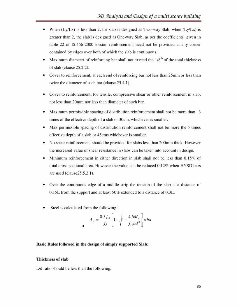
• Steel is calculated from the following :
•
bdbdf
M
fy
fA
ck
uck
st ×
−−=
2
6.411
5.0
Basic Rules followed in the design of simply supported Slab:
Thickness of slab
L/d ratio should be less than the following:
3D Analysis and Design of a multi storey building
36
• Simply supported slab = 20
• Continuous slab = 26
• Cantilever slab = 7
In any case of the above, the thickness should not be less than 100mm
Effective span
• Distance between centre to centre of support
• Clear span plus effective depth
Minimum main reinforcement
• 0.15% gross c/s of slab – for MS bars
• 0.12% gross c/s of slab – for HYSD bars
Spacing of main bars
The spacing or c/c distance of main bars shall not exceed following:
• Calculated value
• 3d
• 300mm
Distribution or Temperature reinforcement
This reinforcement runs perpendicular to the main reinforcement in order to distribute the
load and to resist the temperature and shrinkage stresses.
It should be at least equal to;
• 0.15% gross c/s of slab – for MS bars
• 0.12% gross c/s of slab – for HYSD bars
Spacing of distribution bars
The spacing or c/c distance of distribution bars shall not exceed the following
• Calculated area
• 5d
• 450mm
3D Analysis and Design of a multi storey building
37
Diameter of bars
The diameter of the bars varies from 8mm to 14mm and should not exceed 1/8th of the overall
depth of the slab.
For distribution steel, the diameter varies from 6mm to 8mm.
Cover
The bottom cover for reinforcement shall not be less than 15mm or less than the diameter of
such bar.
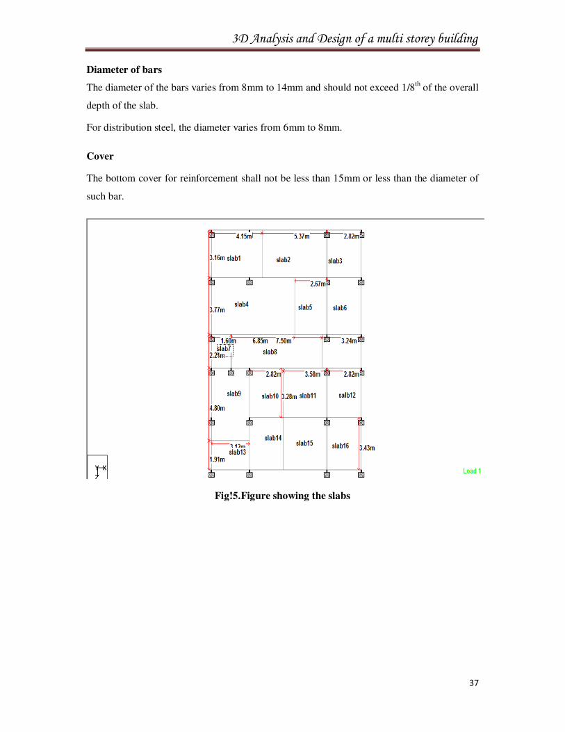
Fig!5.Figure showing the slabs
3D Analysis and Design of a multi storey building
38
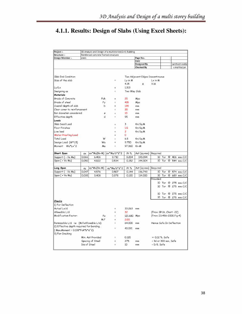
4.1.1. Results: Design of Slabs (Using Excel Sheets):
3D Analysis and Design of a multi storey building
65
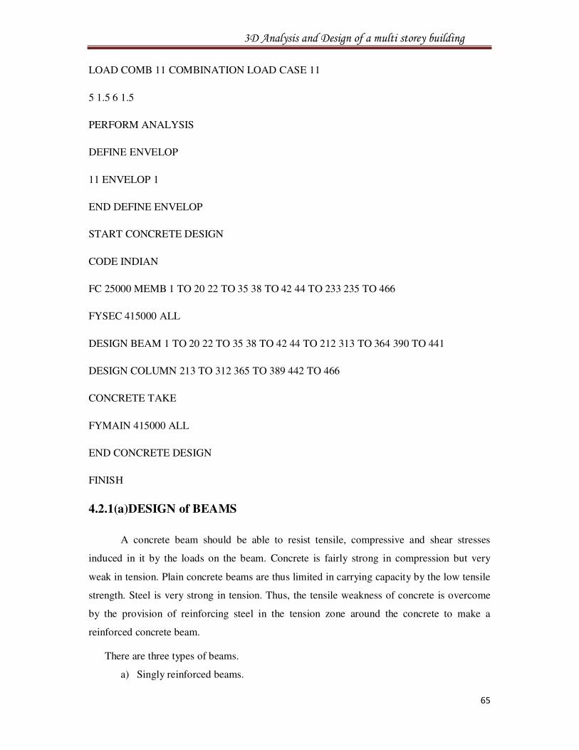
LOAD COMB 11 COMBINATION LOAD CASE 11
5 1.5 6 1.5
PERFORM ANALYSIS
DEFINE ENVELOP
11 ENVELOP 1
END DEFINE ENVELOP
START CONCRETE DESIGN
CODE INDIAN
FC 25000 MEMB 1 TO 20 22 TO 35 38 TO 42 44 TO 233 235 TO 466
FYSEC 415000 ALL
DESIGN BEAM 1 TO 20 22 TO 35 38 TO 42 44 TO 212 313 TO 364 390 TO 441
DESIGN COLUMN 213 TO 312 365 TO 389 442 TO 466
CONCRETE TAKE
FYMAIN 415000 ALL
END CONCRETE DESIGN
FINISH
4.2.1(a)DESIGN of BEAMS
A concrete beam should be able to resist tensile, compressive and shear stresses
induced in it by the loads on the beam. Concrete is fairly strong in compression but very
weak in tension. Plain concrete beams are thus limited in carrying capacity by the low tensile
strength. Steel is very strong in tension. Thus, the tensile weakness of concrete is overcome
by the provision of reinforcing steel in the tension zone around the concrete to make a
reinforced concrete beam.
There are three types of beams.
a) Singly reinforced beams.
3D Analysis and Design of a multi storey building
66
b) Double reinforced beams &
c) Flanged beams.
a) SINGLY REINFORCED BEAMS:
In singly reinforced simply supported beams reinforcing steel bars are placed near the
bottom of the beam where they are most effective in resisting the tensile bending stresses. In
singly reinforced cantilever beams reinforcing bars are placed near the top of beam.
b) DOUBLY REINFORCED BEAMS:
A doubly reinforced beam is reinforced both in compression and tension regions. The
section of the beam may be a rectangular, T or L section. The necessity of using steel in the
compression zone arises due to two main reasons as follows:
• When the depth of the beam is restricted the strength available from a singly
reinforced beam is inadequate.
• At support of continuous beam where bending moment changes sign.
c) FLANGED BEAMS:
In most reinforced concrete structures, concrete slabs and beams are cast monolithic.
Thus beam form part of the floor system together with the slab. In bending the slab forming
the top part of the beam at mid span would be in compression for a definable width greater
than the width of the rid (or the beam) thus increasing the moment of resistance for given rib
width. At continuous supports the position is reversed. The slab in tension and part of it have
cracked in tension, this beam is equivalent to rectangular section at the supports
IS CODE PROVISIONS:
• The loading on the beam is taken as per clause 24.5 of IS: 456-2000
• For continuous beam with equal/unequal spans and equal/unequal loaded, the bending
moment is obtained by using matrix displacement method.
• Effective span and effective depth of beam is same as explained in slab provisions.
• The beams at mid span are designed as T – beams and the same steel reinforcement is
provided for all beams and the reinforcement provided is minimum.
• At supports when the moment of resistance exceeds the balancing moment, the section is
designed as double reinforced section.
• Minimum reinforcement in the tension shall not be less than yfbd
Ast 85.0=
3D Analysis and Design of a multi storey building
67
⇒Clause26.5.1.1 (a)
• Maximum reinforcement in tension shall not be exceeded by 0.04bD ⇒Clause
26.5.1.1(b).
• Maximum area of compression reinforcement shall not exceed 0.04bD and
reinforcement is enclosed by strength vide ⇒ Clause 26.5.1.2.
• Nominal shear stress for uniform depth shall be calculated from the equation
bd
Vuv =τ ⇒ Clause 40.1
• Minimum shear reinforcement will be provided when τv<τc given in table 19.
• Maximum spacing of shear reinforcement shall not exceed the least of 0.75d or 300 mm
for vertical stirrups vide ⇒ clause 26.5.1.5
• Shear reinforcement shall be provided to carry a shear equal to Vu - bd. The strength of
the shear reinforcement Vs shall be calculated for vertical stirrups.
v
svy
S
dAfVs
87.0= ⇒Clause 40.4(a)
• At least 1/3rd positive moment reinforcement in simple beam and 1/4th positive moment
reinforcement in continuous beam shall extend along the same face of the member in to
the support to a length equal to Ld/3⇒clause 26.2.3.3
• For curtailment, reinforcements shall extend beyond the point at which it is no
longer required to resist flexure for a distance equal to the effective depth of the
member or 12 times the diameter of the bar whichever is greater⇒Clause 26.2.3.1
• The minimum shear reinforcement in the form of stirrups shall be provided such that
vbS
Asv ≥≥≥≥
yf87.0
4.0⇒Clause 26.5.1.6
Where, Asv =Total cross-sectional area of stirrup legs effective in shear
Sv = Stirrup spacing along the length of the member
b = Breadth of the beam or breadth of flanged beam
fy =Characteristic strength of the stirrup reinforcement in
N/mm2whichshall not be taken greater than 415N/mm2.
3D Analysis and Design of a multi storey building
68
• Clear cover for longitudinal reinforcement in a beam, neither less than 25 mm nor less
than diameter of such bar and 15 mm to stirrups
• At each end of reinforcing bar neither less than 25 mm nor less than twice diameter of
such bar.
• At least two bars should be used as tension steel, and not more than 6 bars
should be used in one layer of beam.
• The diameter of hanger bars shall not be less than 10 mm, and of main tension bars 12
mm. The usual diameter of bar chosen for beams are 10, 12, 16, 20, 22, 25, and 32 mm.
When using different sized bars in one layer place the largest diameter bars near the
faces, there as of steel should be symmetrical about center line of column as far
as possible.
• The minimum distance between bars has the diameter of bar or maximum size of
aggregate plus 5 mm. Size of aggregate normally used in India is 20 mm. So that clear
maximum distance between bars should be 25 mm.
• The depth of the beam should satisfy the deflection requirements with respect to L /D
ratios. In addition, for economy, the ratio of overall depth to which should be between 1.5
to 2.0
Specifications Regarding Spacing Of Stirrups In Doubly Reinforced Beams:
• Compression steel placed in doubly reinforced beams also has to be restrained against
local buckling during its action like the compression steel. The same rules regarding
restraining of column reinforcements by lateral ties apply to compression reinforcements
in beams also. Accordingly, the diameter of stirrups (ties) should be 6mm and the pitch
should not be more than the least of the following:
o Least lateral dimension
o 16 times the diameter of longitudinal bar
o 300mm
• Minimum steel is necessary to
o Guard against any sudden failure of a beam if concrete cover burst and the bond to the
tension steel is lost.
o Prevent brittle failure, which can occur without shear steel.

3D Analysis and Design of a multi storey building
69
o Prevent failure that can be caused by tension due to shrinkage and thermal stresses
and internal cracking in the beams.
o d) Holds the reinforcements in place while pouring concrete and act as the
necessary ties for the compression steel and make them effective.
3D Analysis and Design of a multi storey building
70
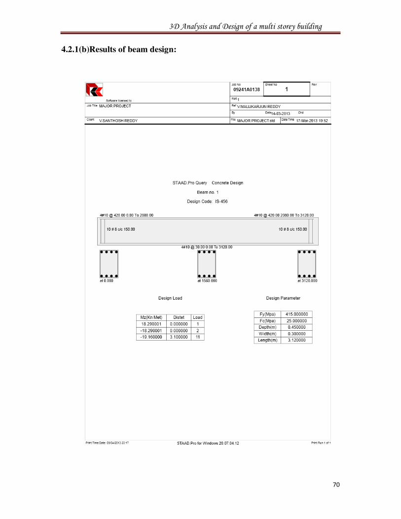
4.2.1(b)Results of beam design:
3D Analysis and Design of a multi storey building
75
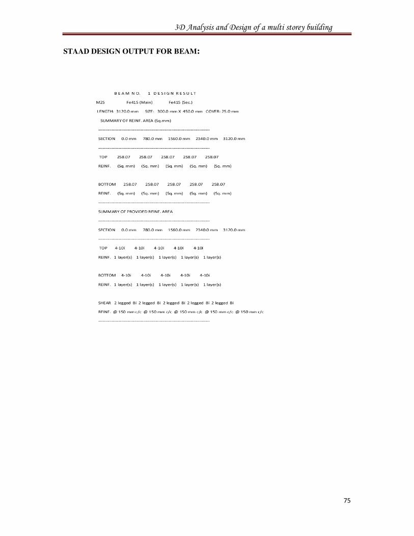
STAAD DESIGN OUTPUT FOR BEAM:
3D Analysis and Design of a multi storey building
76
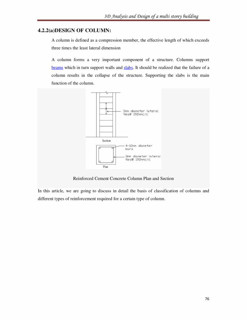
4.2.2(a)DESIGN OF COLUMN:
A column is defined as a compression member, the effective length of which exceeds
three times the least lateral dimension
A column forms a very important component of a structure. Columns support
beams which in turn support walls and slabs. It should be realized that the failure of a
column results in the collapse of the structure. Supporting the slabs is the main
function of the column.
Reinforced Cement Concrete Column Plan and Section
In this article, we are going to discuss in detail the basis of classification of columns and
different types of reinforcement required for a certain type of column.
3D Analysis and Design of a multi storey building
77
A column may be classified based on different criteria such as:
• Based on shape
o Rectangle
o Square
o Circular
o Polygon
• Based on slenderness ratio
o Short column Leff/d <12
o Long columnLeff/d> 12
• Based on type of loading
o Axially loaded column
o A column subjected to axial load and uni-axial bending
o A column subjected to axial load and biaxial bending
• Based on pattern of lateral reinforcement
o Tied columns
o Spiral columns
• Minimum eccentricity
o Emin >(� 500� ) + (� 30� ) > 20
o Where, l = unsupported length of column in ‘mm’
o D = lateral dimensions of column
Types of Reinforcements for columns and their requirements
• Longitudinal Reinforcement:
o Minimum area of cross-section of longitudinal bars must be at least 0.8% of
gross section area of the column.
o Maximum area of cross-section of longitudinal bars must not exceed 6% of the
gross cross-section area of the column.
o The bars should not be less than 12mm in diameter.
o Minimum number of longitudinal bars must be four in rectangular column and
six in circular column.
o Spacing of longitudinal bars measures along the periphery of a column should
not exceed 300mm.
3D Analysis and Design of a multi storey building
78
o Transverse reinforcementmay be in the form of lateral ties or spirals.
o The diameter of the lateral ties should not be less than 1/4th of the diameter of
the largest longitudinal bar and in no case less than 6mm.
• The pitch of lateral ties should not exceed
o Least lateral dimension
o 16 times the diameter of longitudinal bars (small)
o 300mm
• Helical Reinforcement
o The diameter of helical bars should not be less than 1/4th the diameter of
largest longitudinal and not less than 6mm.
o The pitch should not exceed (if helical reinforcement is allowed).
o 75mm
o 1/6th of the core diameter of the column
• Pitch should not be less than,
o 25mm
o 3 times the diameter of helical bar
o Pitch should not exceed (if helical reinforcement is not allowed)
• Least lateral dimension
o 16 times the diameter of longitudinal bar (smaller)
o 300mm
3D Analysis and Design of a multi storey building
79
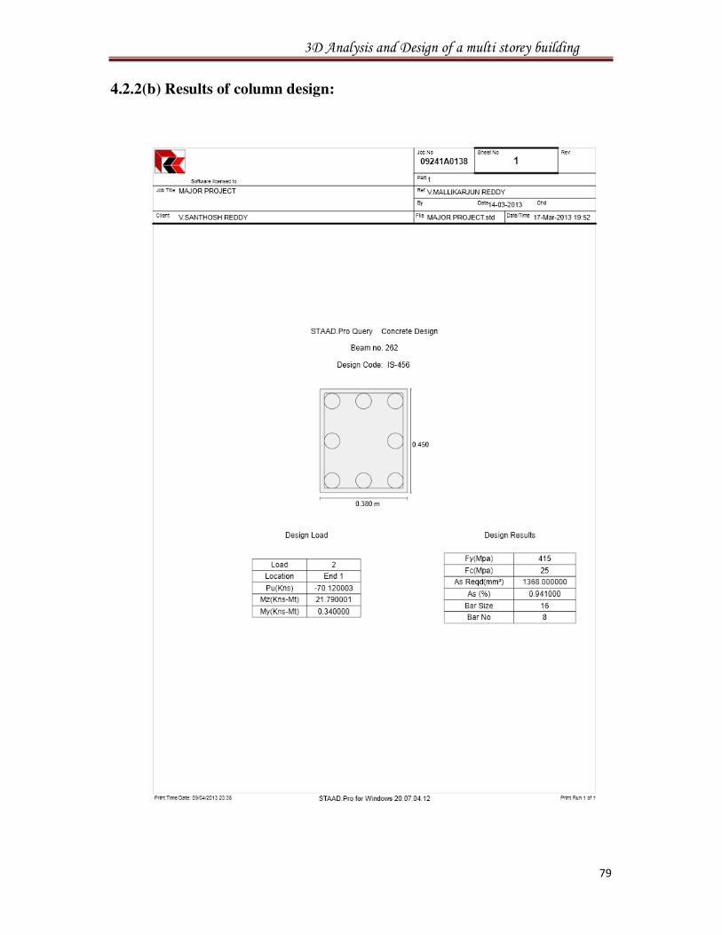
4.2.2(b) Results of column design:
3D Analysis and Design of a multi storey building
84
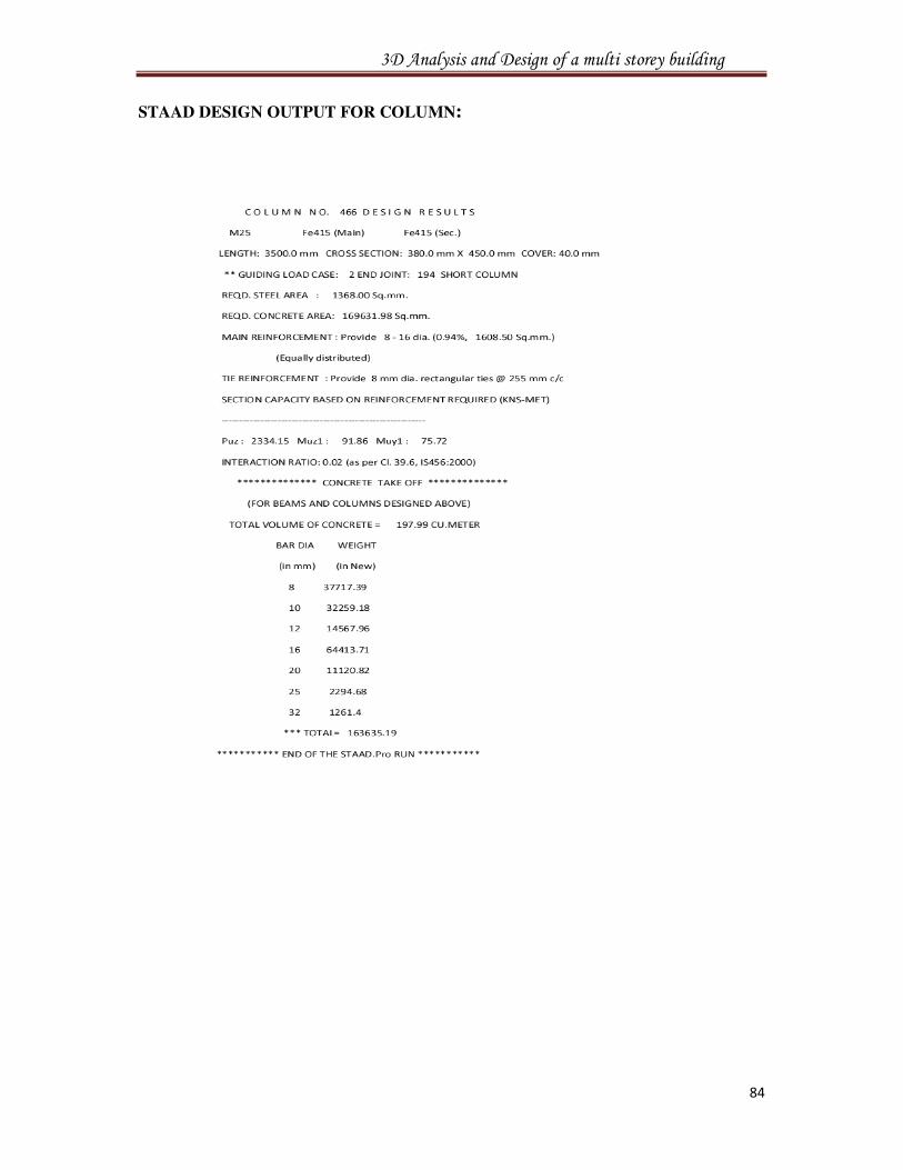
STAAD DESIGN OUTPUT FOR COLUMN:
3D Analysis and Design of a multi storey building
85
4.3. DESIGN OF FOOTINGS USING EXCEL SHEETS:
Footing or foundation is defined as the part of substructure, which transmits the load from
superstructure to surrounding soil stratum safely.
Footings may be Isolated, Combined:
Isolated or independent footings are the footings that support the individual columns.
They distribute and spread the load over a sufficiently large area of the soil stratum to
minimize the bearing pressure. Isolated footings may be square, rectangular or circular.
In general, it is assumed that the soil behaves elastically i.e. the strain in the soil is
proportional to applied stress i.e., stress and strain distribution in the soil immediately under
the base of the footing is linear. Stress distribution is different for different soils.
For analysis purpose, a footing can be compared with a rigid body in equilibrium
subjected to loads. Like other structural members, a footing is designed to resist shear forces
and bending moments. In design, for any soil the pressure distribution is assumed to uniform.
In design, the critical section for one way shear (beam shear) is at a distance equal to
the effective depth, d from the face of column footing. The critical section for two way shear
or slab type shear shall be at a distance d/2 from the periphery of column, perpendicular to
the plane of the slab. The critical section for bending moment is at the face of the column.
Generally the footing is sensitive to punching shear.
3D Analysis and Design of a multi storey building
86
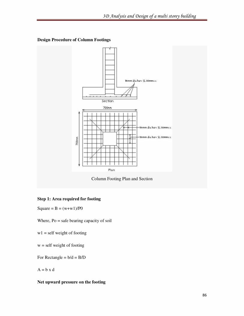
Design Procedure of Column Footings
Column Footing Plan and Section
Step 1: Area required for footing
Square = B = (w+w1)/P0
Where, Po = safe bearing capacity of soil
w1 = self weight of footing
w = self weight of footing
For Rectangle = b/d = B/D
A = b x d
Net upward pressure on the footing
3D Analysis and Design of a multi storey building
87
Q/p = W/A
Step 2: Bending Moment
Critical section for maximum bending moment is taken at the face of the column
For a square footing,
Mxx = q x (B/8) (L – a)2
Mxx = q x (L/8) (B – b)2
Myy = q x (B/8) (L – a)2
Step 3: To fix the depth of the footing shall be greater of the following:
Depth from bending moment consideration
d =�(M/Qb)
where, Q = moment of required factor
Depth from shear consideration.
Check for one way shear
Check for two way shear or punching shear
Critical shear for one way shear is considered at a distance‘d’ from face of the column.
Shear force, V = qB[((B – b)/2) d]
Nominal shear stress, τv = k .τc
τc = 0.16 √Fck
Step 4: Check for two way shear
Critical section for two way shear is considered at a distance at a distance d/2 from all the
faces of the column.
SF, V = q [ B2 – (b + d)2]
SF, V = q [L x B – (a + d)(b + d)]
Nominal shear stress, Tv = V/2((a+d)(b+d)d)
τv = V/4((b+d)d)
3D Analysis and Design of a multi storey building
88
τv = k .Tc
k = 0.5 + β > 1
τc = 0.16 *Fck1/2
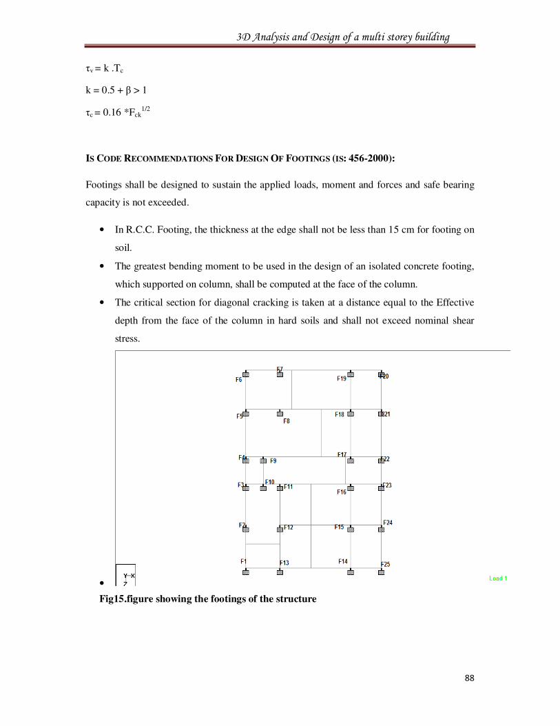
IS CODE RECOMMENDATIONS FOR DESIGN OF FOOTINGS (IS: 456-2000):
Footings shall be designed to sustain the applied loads, moment and forces and safe bearing
capacity is not exceeded.
• In R.C.C. Footing, the thickness at the edge shall not be less than 15 cm for footing on
soil.
• The greatest bending moment to be used in the design of an isolated concrete footing,
which supported on column, shall be computed at the face of the column.
• The critical section for diagonal cracking is taken at a distance equal to the Effective
depth from the face of the column in hard soils and shall not exceed nominal shear
stress.
•
Fig15.figure showing the footings of the structure
3D Analysis and Design of a multi storey building
89
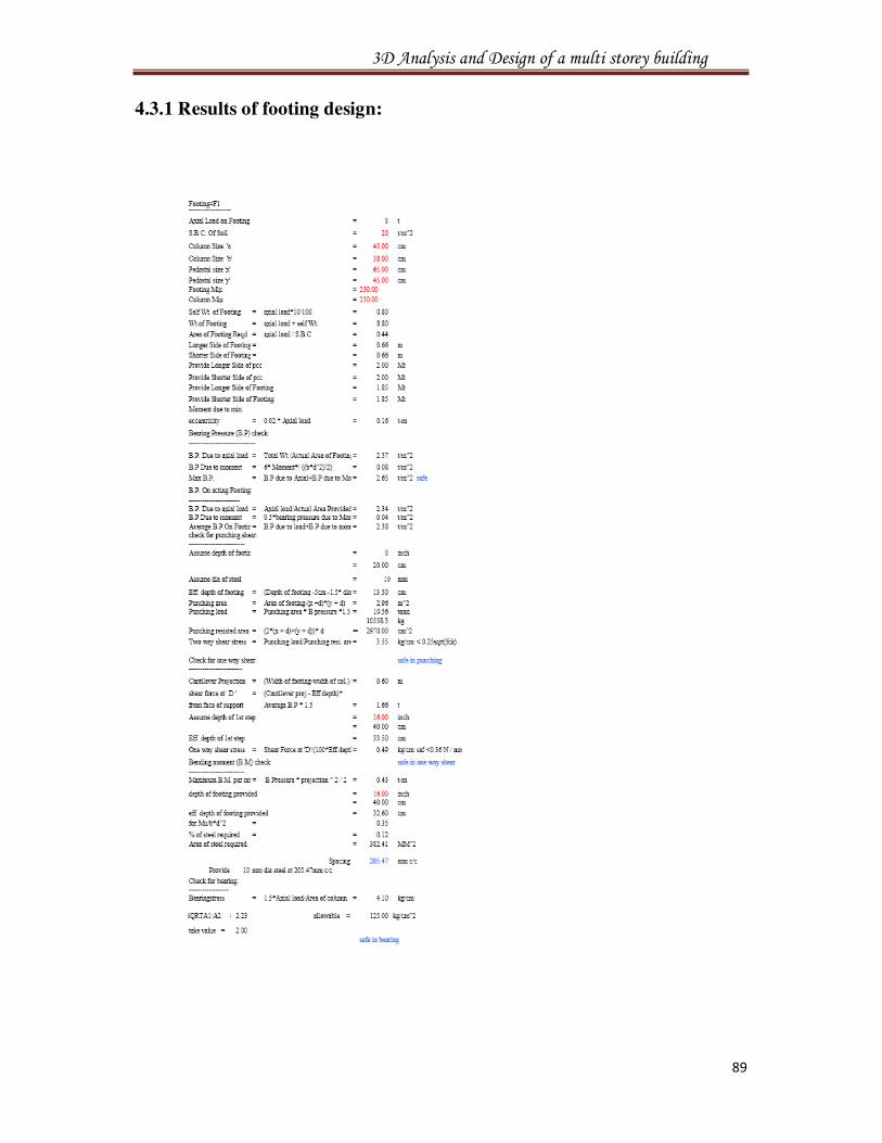
4.3.1 Results of footing design:
3D Analysis and Design of a multi storey building
96
4.4 DESIGN OF STAIR CASE USING EXCEL SHEETS:
The purpose of staircase is to provide pedestrian access to different levels within a building.
The geometrical forms of staircases may be quite different depending on the individual
circumstances involved.
• They are two main components of a staircase
o Stairs
o Landing slab.
The stairs and landing slab can be arranged in different forms to get different types of
staircases. In the shape and structural arrangement of a staircase would generally depend on
two main factors.
a. Type of construction of the structure around the stair case i.e. load bearing
brick structure or reinforced concrete structure
b. Availability of space
• Classification of Staircases:
o Straight stair
o Quarter turn stair
o Half turn stair (open newel type or open well stair)
o Dog-legged stair
o Open newel stair with quarter space landing
o Geometrical stairs such a circular stair, spiral stair etc.
• General Principles:
o Between consecutive floors there should be an equal rise per every parallel
step. Similarly there should be equal going
o There should be at least 2m head room measured vertically above any step.
o The sum of going of a single step plus twice the rise should be between
550mm and 700mm.
o The rise of step should not be more than 200mm.
o The slope or pitch if stair way should not be more than about 380.
Effective Span in Stairs:
The effective span of stairs without stringer beams shall be taken as the following
horizontal distances:
3D Analysis and Design of a multi storey building
97
• Where supported at top and bottom risers by beams spanning parallel with the risers,
the distance center to center of beams,
• Where spanning on to the edge of a landing slab, which spans parallel, with the risers,
a distance equal to the going of the stairs plus at each end either half the width of the
landing or one meter, whichever is smaller, and
• Where the landing slab spans in the same direction as the stairs, they shall be
considered as acting together to form a single slab and the span determined as the
distances center to center of the supporting beams or walls, the going being measured
horizontally.
DISTRIBUTION OF LOADING:
In the case of stairs with open wells, where spans partly crossing at right angles occur,
the load on the areas common to any two such spans may be taken as one half in each
direction. Where flights or landings are embedded into walls for a length of not less than
110mm and are designed to span in the direction of the flight, a 150mm strip may be
deducted from the loaded area and the effective breadth of the section increased by 75mm for
purpose of design.
In this, stairs spanning longitudinally, the beam is supported at top and at the bottom of
flights.
Loads
• Self weight of a step = 1 x R/2 x 25
• Self weight of waist slab = 1 x t x 25
• Self weight of plan = 1 x t x 25[(R2 + T2)/T]
• Live load = LL (KN/m2)
• Floor finish = assume 0.5 KN/m
For the efficient design of an RCC stair, we have to first analyze the various loads that are
going to be imposed on the stair.
The load calculations will help us determine, how much strength is required to carry the load.
The strength bearing capacity of a staircase is determined on the amount of steel and concrete
used.
The ratio of steel to concrete has to be as per standards. Steel in the staircase will take the
tension imposed on it and the concrete takes up the compression.
These are the essential steps that are to be followed for the RCC Stair Design.
3D Analysis and Design of a multi storey building
98
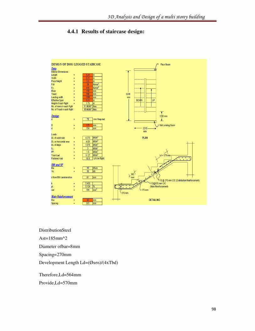
4.4.1 Results of staircase design:
DistributionSteel
Ast=185mm^2
Diameter ofbar=8mm
Spacing=270mm
Development Length Ld=(Øxσs)/(4xTbd)
Therefore,Ld=564mm
Provide,Ld=570mm
3D Analysis and Design of a multi storey building
99
5. SUMMARY
• The design of slab, beam, column, rectangle footing and staircase are done in limit
state method which is safe at control of deflection and in all aspects.
• For the construction of residential building, the safe bearing capacity is taken as
200 KN/m² in order to bear all the loads coming on to the building.
• Using Staad.pro software, the design consideration has been taken as per the
IS codes. The design is safe in all conditions.
• On comparison with the drawings, manual design and the geometrical model
developed using staad.pro; the area of the steel requirement for the beam,
Column, footing and slab are comparatively similar to that of the requirement.
• The percentage of variation in area of steel for the beams, column, footing and slab
are less than 20 percent of the required steel.