Embed Size (px)
Citation preview

© Fraunhofer ILT
30th of January 2017
Next Generation Manufacturing:Industry 4.0 and Digital Photonic Production
Fraunhofer-Institut für Lasertechnik ILTSteinbachstraße 1552074 Aachen
Prof. Dr. Reinhart [email protected]

© Fraunhofer ILT
Digital Photonic Production and its impact on Industry 4.0
Example 1: Ultrafast Processing and Ablation
Example 2: Laser Metal Deposition LMD
Example 3: Selective Laser Melting SLM
Example 4: New Production chain for Precision Optics
Contents

© Fraunhofer ILT
1st Industrial
Revolution
1st Industrial RevolutionIntroduction of mechanical
production facilities powered by
water and steam
2nd Industrial RevolutionIntroduction of mass production
based on the division of labour
powered by electrical energy
3rd Industrial RevolutionIntroduction of electronics and
IT for the further automation
of production
4th Industrial RevolutionBased on cyber-physical
production systems

© Fraunhofer ILT
Industry 4.0 and its Impact
Technology
networked
within a
machine or
product
multicore
technology,
ubiquitious,
with unlimited
connectivity
Internet of Things
Smart Factory
Improved
efficiency in
tooling and
maintenance
"Lot size 1"
CPS-equipped
products under
assembly steer
the production
process, making
production
extremely flexible
and efficient
Digital Business
Manual or semi-
automatic control of
production and business
"Digital Company"
Automated digital
interaction between
machinery, business
process management,
external partners
(suppliers, logistics,
distributors), and
customers
Fully integrated digital business
To
da
yTo
mo
rro
w
Workforce
Skilled labour,
adaptive
organisation
"Expert All-
Rounder"
Multi-competent,
flexible workforce,
interacting on all
levels of business
and with partners
Cyber-Physical
Systems
Embedded
Systems

© Fraunhofer ILT
Digital Photonic Production – A new Industrial Revolution?
Product complexity
ConventionalProduction
Lot size
Cost Cost
ConventionalProduction

© Fraunhofer ILT
Digital Photonic Production – A new Industrial Revolution?
Product complexity
ConventionalProduction
Lot size
ConventionalProduction
Individualisation for free Individualisation for free
Cost Cost
laser based manufacturinglaser based manufacturing

© Fraunhofer ILT
Product complexityLot size
Individualisation for free Individualisation for free
Cost Cost
DigitalPhotonic Production
DigitalPhotonic Production
Laserstrahl
umgeschmolzene
Schicht
Schmelzbad
Bewegungsrichtung
des Laserstrahls
Pulverschicht
SLM 1-3 cm3 / min LMD 10-30 cm3 / min Ablation 0,2-0,5 cm3 / min
laser based manufacturinglaser based manufacturing
ConventionalProduction
ConventionalProduction
Digital Photonic Production – A new Industrial Revolution?
© Fraunhofer ILT
Impact of Digital Photonic Production to Industry 4.0 –The Aachen perspective
physical
cyber
hardwaresoftware
4. Industrielle Revolution
Kollaborations-
produktivität- Mensch/Mensch
- Mensch/Maschine
- Maschine/Maschine
IT-Software: truth
PLM-Systems
ERP-Systems
Physical Systems:
automation
Cognitive Systems
Social Behavior:
cooperation
Business
Communities
Social
Communities
IT-Hardware: speed
Saving to the
cloud
High Speed
Computing
Sensor technology
© SICK AG
4th industrial revolution
Collaboration-
productivity- human/human
- human/machine
- machine/machine

© Fraunhofer ILT
Digital Photonic Production –“Directly from CAD to Product”
Using light as a tool means …
highest power density
highest speed
shortest interaction (precision)
mass-less, force-less, no tools
best controllability (CAD to product)

© Fraunhofer ILT
Example 1: Ultrafast Processing
Why fs-pulses?

© Fraunhofer ILT
Time Scales of Thermal Processes – Melt Film Thickness
Material depth z
Melt temperature
Vaporization temperature
Environmeltal temperature
Tem
pera
ture
T
Melt film thickness
Heat penetration depth T0
TS
TV
Steel
Pulse duration t [s]
Aluminium
Heat
pen
etr
atio
nd
ep
thd
th
[m]
10-15
10-10
10-7
10-4
10-12 10-9 10-6 10-3
tth d 410-8
10-9
10-5
10-6
10-3
m/s61012
m/s61097
t
zierfct
ITtzT abs
44, 0

© Fraunhofer ILT
Steel Ceramics Polymers
BasicsMaterials
Ceramic-Substrates for printed circuit boards
Ceramic micro components
PCD- andSapphire-Tools
Injection molding tools
Forming tools
Tribological structures
Medical technology
Micro fluidics
Micro optics

© Fraunhofer ILT
Innoslab Platform – History
1994 1996 1998 2000 2002 2004 2006 2008 2010 2012
Patentpartiallypumpedslab laser
Patentslabamplifier
FoundationofEdgeWave2001
FoundationofAMPHOS2010
First demon-stration
Nd:Innoslabamplifier
50 W
Nd:InnoslabCWOscillator
1 kW
ATLAS LIDAR source
100 mJ
Nd:Innoslabamplifier
400 W ns, ps
Yb:Innoslabamplifier
kW fs

© Fraunhofer ILT
Multipass ThinDisk Amplifier – record fs power
Seeder
Innoslab MOPA
630 W Power Amplifier
ThinDisk Multiplass Amplifier
CW pumped
18 reflections on disk
Demonstrated Results
1.5 kW output
37.5 µJ
711 fs
M² = 1.5 x 2.0

© Fraunhofer ILT
high reprate / low pulse energy
System strategies for productivity increase
Increase of average laser power byhigh pulse repetition rate
thigh pulse energy / low reprate

© Fraunhofer ILT
Applications of ultrafast machining-high precis ion structuring of emboss ing and injection molding tools
• Clear replication of CAD-Data• No melt and debris• Surface roughness < 0.5 µm
3D-Structuring of emboss ing rolls
Material: Copper, chrome-platedRoll: 250 mm diameter, 1 m lengthRoller rotation speed: 1400 U/min Line scan distance : 2 µm-> surface speed: 15 m/s-> spot distance @ 2 MHz: 7,5 µmLaser power: 100 WSpot size: 10 µmRepetion rate: 3 MHz
5 mm

© Fraunhofer ILT
Cutting with Ultra-Short-Pulse Lasers
exit side
HAZ ≈ 70 µm
entry side
HAZ ≈ 250 µm
P = 400W , F = 1 J/cm², frep= 6.3 MHz
Repetitive ablation of 300 µm kerf
Cutting speed 0.3 m/min
HAZ <25 µm in low power range <100 W
CFRP processing with EdgeWave ps laser at 30 W

© Fraunhofer ILT
high reprate / low pulse energy
System strategies for productivity increase
Increase of average laser power byhigh pulse repetition rate
thigh pulse energy / low reprate

© Fraunhofer ILT
Increasing Producivity - Influence of Pulse Energy
Nano structuring withRipple-Formationat low pulse energies
Micro structuringWith production of cone like protusions at high pulse energies

© Fraunhofer ILT
Large Area structuring with laser radiation
Micro structuring of wind rotors- Anti icing- Anti sticking of insects- Structur size < 10 µm
Micro- and nano structuresto generate functionalsurfaces
Quelle:fos4x
Quelle:phereclus

© Fraunhofer ILT
t
high reprate / low pulse energy
System strategies for productivity increase
Increase of Pulse energy and beam splitting
high pulse energy / low reprate
t
t
t
t
Multiple beams withreduced fluence

© Fraunhofer ILT
MultiBeamScanner (MBS)Optical Principle
Laser process ing with a spot array instead of a s ingle spot

© Fraunhofer ILT
Laser structuring of motor components
Aim: Reduction of friction and wear
Approach: Micro and nano structuring ofcylinder liners and piston rings
Use of high power ultra short pulsed lasers
Cylinder liner
Piston ring

© Fraunhofer ILT
Micro holes in airfoils for interface designing
- Hole diameter < 200 µm- Variable hole pattern/ drilling sequence- Shaped holes for improved gas flow
Drilling rate > 10.000 holes /sec
Different drilling techniques
Single Pulse
Percussion
Helical drilling
Quelle:Airbus
Large Area structuring with laser radiation
Reduction of fuel use: >10%

© Fraunhofer ILT
Programmable Multi Beam Hybrid Optics (Spacial Light Modulators)
Combination Scanner + Programmable Diffractive Optics(PDO)
20-40 single beams
Up to 10 µJ/beam
>10.000 holes / s

© Fraunhofer ILT
Change of beam profile „on the fly“
Switching time 20ms
300µm
Programmable Multi Beam Hybrid Optics

© Fraunhofer ILT
Example 2: LMD

© Fraunhofer ILT
LMD: Generation of Part directly from CAD Data
CAD Data“Slicing”
Part
Steel (316L)
Construction
time 20 min

© Fraunhofer ILT
Laser Metal Deposition LMD
Process
BLISK Blade additivelymanufactured by LMD

© Fraunhofer ILT
LMD – ALSI10MG.
RESULTS TENSILE TESTING.
Fig.: “Minimal” strength of cast and AM aluminum (tensile testing)[Casting: DIN EN 1706; LMD: Thiele; SLM: Buchbinder]
0
2
4
6
8
10
12
14
16
0
50
100
150
200
250
300
Fmin - pressurecasting
Fmin - die casting Fmin - sandcasting
Fmin - LMD Fmin - SLM
Elo
ng
ati
on
at
bre
ak
At
[%]
Yie
ldst
ren
gth
Rp
0,2
, t
en
sile
stre
ng
thR
m[M
Pa
]
yield strength tensile strength
elongation at break

© Fraunhofer ILT
Power Cladding with oscillating solidification front
Page 32
Objective: generation of small grains
cross section of cube – 4 layers
EBSD analysis
determination of working point via numerical modelling
oscillation frequency too small
oscillation frequency suitable
© Fraunhofer ILT
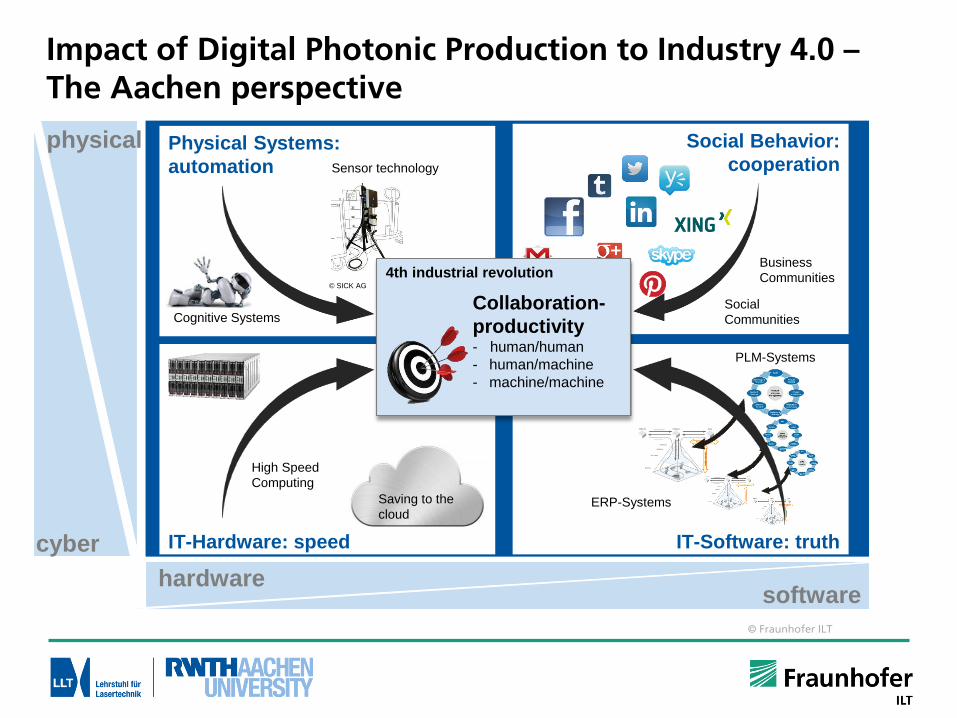
Laser Metal Deposition – SX on SX
three layers with overlapping tracks
cross section
Page 33
Microstructure with one dendrite growth direction
no stray grains
no cracks
730
µm
230 µm
growth direction of dendrites
eviation of crystal orientation on top of the deposit
EBSD analysis
© Fraunhofer ILT
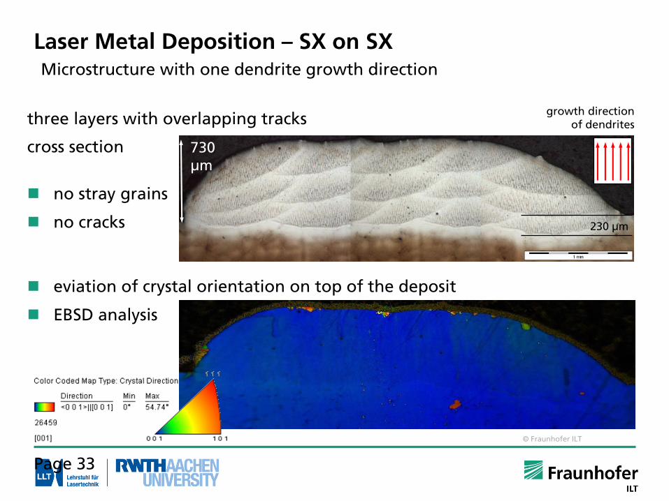
UNCONVENTIONAL MATERIAL PAIRINGSMMCs on grey cast iron, 30/min, up 20x
Disc brakes
Diameter: Ø 50 mm Length: 1 m
Cross-section
APPLICATIONS
Results
1:1 wt.-% | WC : IN625
Dilution < 1 %
Single layer thickness approx. 60 µm Diameter: Ø 300 mm
© Fraunhofer ILT
Example 3: Selective Laser Melting

© Fraunhofer ILT
The AM Revolution
Basic Patent
2003
First Implant
...to SeriesProduction
...fromPrototyping
1996First Production
2008
Engine Block?
20??
2001
First Tool Insert
SLM as one of the key enablers of AM
Lowering ofbuild platform
Laser Melting ofpowder material
Deposition ofpowder layer

© Fraunhofer ILT
Example:TiAl6V4 – Static Mechanical Properties
0,0
5,0
10,0
15,0
20,0
25,0
30,0
0
200
400
600
800
1000
1200
SLM WB 1 SLM WB 2 SLM HIP Fräsen MIM Feinguss Schmieden
Bre
ak
ing
Elo
ng
ati
on
A5
[%]
Te
nsi
le S
tre
ng
th R
m[M
Pa
]
Zugfestigkeit
BruchdehnungStandards ASTM F136
Tensile Strength
Breaking Elongation
Milling Casting Forging
SLM parts with adapted heat treatment (WB) achieve same static mechanical properties as forged/milled parts
SLM- Part properties

© Fraunhofer ILT
Component design with lattice structures –Stiffness, strength, energy absorption
=𝑉𝑜𝑙𝑢𝑚𝑒 𝑜𝑓 𝑙𝑎𝑡𝑡𝑖𝑐𝑒 𝑠𝑡𝑟𝑢𝑐𝑡𝑢𝑟𝑒
𝐶𝑢𝑏𝑖𝑐 𝑒𝑛𝑣𝑒𝑙𝑜𝑝𝑒 𝑣𝑜𝑙𝑢𝑚𝑒
F2ccz-type latticestructure for tensiletests
Yield
strength

© Fraunhofer ILT
Integrative ProductionExample: Race car axle, 30% increase of stiffness

© Fraunhofer ILT
Biodegradable Scaffold (WE43) Topology Optimized Triple Clamp (AZ91)
1:4 Scale Model
Ø 98mm build plate
Research Activities: New MaterialsMagnesium Alloys

© Fraunhofer ILT
Pseudoplasticity (shape memory effect) or super elasticity adjustable by choice of process parameters
Smallest feature size:approx. 30µm
Surface roughness Sa:< 2µm
MechanicalDeformation
100µm
Heating
Heating
Heating
Research Activities: New MaterialsShape memory alloys (NiTiNol)

© Fraunhofer ILT
Research activities: DesignMonolithic Functional Parts

© Fraunhofer ILT
Machine Concepts
Cost per part
Lot size
Conventional manufacturing
Selective Laser Melting (SLM)
High Power SLM machine
New AM machine
No clear trend in machine technology development
Parallelization of SLM processes
Usage of multiple lasersources
Two scan field Multi beams
Increase of laser power
Laser power up to 1 kW
Increase of laser beam diameter
Skin-Core principle
New System apprach„SLM 2.0“

© Fraunhofer ILT
Productivity – High Power SLMPylon Bracket Application
“Skin-Core”
1 mm skin thickness
1 kW core processing
300 W skin processing
“Conventional”
300 W processing (same parameters as skin)
30% decrease in built-up time due to skin-core processing

© Fraunhofer ILT
x
y
New SLM machine concept at ILTMulti-Spot processing
Conventional SLM New Multispot concept

© Fraunhofer ILT
SLM machine concept IIILaboratory Set-up of the Multi-Spot SLM machine
Productivity up 20-50x
Main advantages as a matter of principle:
Use of diode lasers
Easy upscaling in productivity (higher number of laser spots)
Easy upscaling in build size (larger axes)
Local shielding gas flow, local process control unit

© Fraunhofer ILT
Example 4: New Production chain for precision Optics

© Fraunhofer ILT
Research aim: manufacturing of glass optics with laser radiation, especially aspheres and freeform optics
Manufacturing time independent from surface geometry
Vision: Fully Laser-based Optics ManufacturingDigital Photonic Production for Photonic Devices

© Fraunhofer ILT
Process aim: Processing of the geometry in short time with moderate roughness
Process principle:
Ablation of glass material through heating above ablation temperature
cw or pulsed CO2-laser radiation
Preheating for lower thermal stresses
Main process parametersPL, Δys, vs, n
Results :High ablation rate 𝑽 ≥ 20 mm³/s(1200 mm³/min) with 1.2 kW CO2 laser
Geometry Manufacturing by High Speed Laser Ablation

© Fraunhofer ILT
Geometry Manufacturing by High Speed Laser AblationSample 20x20x5 mm³

© Fraunhofer ILT
Laser Polishing of GlassProcedural Principle and Experimental Setup
CO2-laser, = 10.6 µm, PL,max = 1.5 kW
Beam path
Z-Axis
X-Axis
Scanner
Heating plate
Extraction system
Crossjet
Flowbox
Pyrometer(not visible)
bLine
PL
vs
vfeed
bfield
lLine
TPreheat
Reducing glass viscosity through heating Material flow due to surface tension
-> Polishing without material removal Quasi-Line focus through high scan
speed vs
Preheating for lower thermal stresses

© Fraunhofer ILT
Laser Polishing of GlassGrinded Spherical Lens, Fused Silica, 25 mm

© Fraunhofer ILT
Laser Polishing of GlassRoughness, Fused Silica
Conv. pol.(/20)
Laser Polishing
mic
ro
rou
gh
ness
wa
vin
ess
micro roughness waviness
RMS 50 x 70
µm²
Rq1 x 1 mm²
Wq16 x 16
mm²
PV20 x 20
mm²
Conv. pol. (/20)
0,39 nm 0,3 nm 2,5 nm 0,3 µm
Laserpolished
0,33 nm 1,0 nm 6,1 nm 5,2 µm
Processing time for laser polishing: 1 - 5 s/cm²
Not sufficient for imaging optics yet-> Laser form correction by ablation

© Fraunhofer ILT
Summary
Significant impact of DPP on Industry 4.0
Multi-Process realization of DPP
- Ultrafast Ablation
- LMD
- SLM
- Combined process chains:
e.g. Ultrafast Ablation and Polishing
Many industrial apps demonstrated
Perspective of 30x increased productivity in next 5-10 years
QUESTIONS?

© Fraunhofer ILT
End of Presentation