Embed Size (px)
Citation preview

IJSART - Volume 3 Issue 10 – OCTOBER 2017 ISSN [ONLINE]: 2395-1052
Page | 76 www.ijsart.com
Design, Analysis And Manufacturing Process Generation For Steel Tooth Drill Bit
K Kiran Kumar1, S Mohan Kumar2, Vangar Sachin3
1, 2 Assistant Professor, Dept of Mechanical Engineering 3Dept of Mechanical Engineering
1, 2, 3 AVN Institute of Engineering & Technology, Hyderabad, India.
Abstract- The aim of the project is to design, analysis and manufacturing process generation for Steel Tooth Drill Bit on CNC Multi-axis machine.A Steel tooth drill bit is a drilling cutter bit used for cutting the rock to make cylindrical holes by rotary drilling method. This steel tooth series of Products designed specifically for enhancing durability, increasing the rate of penetration for excellent drilling performance for use in activities like digging wells, oil fields, mineral exploration, preparing foundations in the construction and mass demanding environments.
Using the software NX UNIGRAPHICS Steel tooth drill bit 3D model tool is designed and followed by structural analysis is carried out by using ANSYS software. By using NX-CAM software generated the part program by defining the proper tool path and NC code.
The material is considered for the manufacturing process of steel tooth drill bit is mild steel because it is one of the hardest materials and its cost is comparatively low is used in an enormous range of applications and it provides material properties that are acceptable for many applications. It can be strengthened by the addition of carbon. Since the properties of carbides steels are very close to properties of mild steel, for that reason mild steel is considered for the manufacturing process for Steel Tooth Drill Bit.
I. INTRODUCTION This project deals with the design, analysis, and tool path generation for “STELL TOOTH DRILL BIT” piece using UGNX CAM software. It is a CAD/CAM software used to generate part program through designing and feeding the geometry of the component and defining the proper tool path and accordingly transferring the generated part program to the required CNC machine with the help of DNC lines execute the program with appropriate requirements.
A Steel Tooth drill Bit is using for cutting the rock. A tool head with cutters prepared by hard material, this steel tooth series of products delivers the fast rate of penetration and new hard metal guard for life-enhancing stability in the
mass demanding environments. A drill bit is a tool designed to make a usually cylindrical hole by the rotary drilling method for the discovery and extraction of hydrocarbons such as crude oil and natural gas. The essential issue in rock working is the breakage of sections out of the substance of a strong wall of rock. It happens when the tool forcing into the rock surface and it used for testing surface hardness. Since the process breaks rather than cuts solid rock into small fragments of mixed sizes, it can be regarded as fundamentally one of crushing. As in crushing procedure usually, energy/volume relationships and ‘Specific energy’ are the energy important to exhume unit volume of rock.
In drilling data from some of the sources, its
minimum value appears; usually associate with the crushing strength of the medium drilled in, for rotary, percussive-rotary and roller-bit drilling.
• High-quality developed • Product and process improvement • Delivering integrity in all of our relationships • duty towards health, safety, and the environment • Creating customers for life
II. 3D MODELLING OF TO STEEL TOOTH DRILL
BIT INPUTS FOR THE PROJECT: 2D Drawing A 2D drawing used to design a 3D model for this steel tooth component using UNIGRAPHICS NX 7.5 CAD software. In below 2D drawing shows the drawings of the Steel tooth drill bit with all the essential dimensions and GD&T representations the best and superior for manufacturing the component without any errors.

IJSART - Volume 3 Issue 10 – OCTOBER 2017 ISSN [ONLINE]: 2395-1052
Page | 77 www.ijsart.com
Fig.1 2D input of steel tooth drill bit
Below image shows the geometry for the extrude feature.
Fig: Extrude option of the steel tooth drill bit
Below image shows the all views of the steel tooth drill bit.
Fig: Final 3D model of the steel tooth drill bit in different
views III. FINITE ELEMENT ANALYSIS OF STEEL TOOTH
DRILL BIT
Modal Analysis of the Structure The Modal analysis used to conclude the mode shape of the structure and natural frequency. The operating
frequency identified for the structure to avoid harmful effects from the natural frequency of the structure (resonance conditions). First 10Natural Frequencies of Steel tooth drill bit.
Modal analysis of the structure is performed using
Bloc LANCZOS method. Natural frequencies of the structure from modal analysis listed in the above table. Fig: Below shows the 1st mode shape of the structure at the frequency of 1500 Hz.
MODE 1 MODE2
MODE3 MODE4
HARMONIC ANALYSIS OF STEEL TOOTH DRILL BIT
Any continuous cyclic load will create a continuous cyclic response in a structural system. Harmonic response study gives the capability to forecast the dynamic behaviour of structures, thus enable to confirm whether your designs will effectively conquer resonance, fatigue, and other harmful effects of forced vibrations.
IJSART - Volume 3 Issue 10 – OCTOBER 2017 ISSN [ONLINE]: 2395-1052
Page | 78 www.ijsart.com
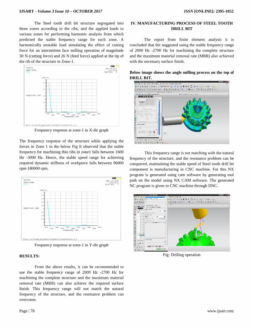
The Steel tooth drill bit structure segregated into three zones according to the ribs, and the applied loads to various zones for performing harmonic analysis from which predicted the stable frequency range for each zone. A harmonically unstable load simulating the effect of cutting force for an intermittent face milling operation of magnitude 30 N (cutting force) and 26 N (feed force) applied at the tip of the rib of the structure in Zone-1.
Frequency response at zone-1 in X-dir graph
The frequency response of the structure while applying the forces in Zone 1 in the below Fig It observed that the stable frequency for machining thin ribs in zone1 falls between 1600 Hz -3000 Hz. Hence, the stable speed range for achieving required dynamic stiffness of workpiece falls between 96000 rpm-180000 rpm.
Frequency response at zone-1 in Y-dir graph
RESULTS: From the above results, it can be recommended to use the stable frequency range of 2000 Hz -2700 Hz for machining the complete structure and the maximum material removal rate (MRR) can also achieve the required surface finish. This frequency range will not match the natural frequency of the structure, and the resonance problem can overcome.
IV. MANUFACTURING PROCESS OF STEEL TOOTH DRILL BIT
The report from finite element analysis it is concluded that the suggested using the stable frequency range of 2000 Hz -2700 Hz for machining the complete structure and the maximum material removal rate (MRR) also achieved with the necessary surface finish. Below image shows the angle milling process on the top of DRILL BIT.
This frequency range is not matching with the natural
frequency of the structure, and the resonance problem can be conquered, maintaining the stable speed of Steel tooth drill bit component is manufacturing in CNC machine. For this NX program is generated using cam software by generating tool path on the model using NX CAM software. The generated NC program is given to CNC machine through DNC.
Fig: Drilling operation

IJSART - Volume 3 Issue 10 – OCTOBER 2017 ISSN [ONLINE]: 2395-1052
Page | 79 www.ijsart.com
Fig: Final model of steel tooth drill bit
TOOL DESCRIPTION:
V. CONCLUSION
The Steel tooth drill bit 3D model is designed by using NX-CAD software then drill bit structure with row placement, tooth spacing is considered for analysis. Modal analysis has been performed to know the behaviour of the structure and to determine the natural frequencies and cutter geometry. Graphical representation of Harmonic analysis on steel tooth drill bit at different cutting speed has been carried out to predicting the stable speed range for machining the structures. From the analysis results, it is recommended to use the stable speed range of 2000 -2700 Rpm for machining the complete structure. Then the component will be free from vibrations, and superior surface finish obtained. By using the NX-CAM software, the NC program is generated.
REFERENCES [1] Finite Element Analysis by P.K VenkatRamana and V.
Balasingaravelan. [2] AKIN, J. E. Application, and Implementation of Finite
Element Methods,
[3] BEEKER, A.A. The Boundary Element Method in Engineering, McGraw-Hill,
[4] The Strength of materials by S. Ramamrutham. [5] A book of tool design by Pollack, Publisher: Reston Pub.
Co, 1976 [6] Research, Industrial Systems (2002-05-20). [7] Mechanical finish designations retrieved 2009-01-04. [8] Degarmo, black & kosher (2003), materials and processes
in manufacturing (9th ed.), Wiley. [9] Whitehouse, DJ. (1994). Handbook of surface metrology,
Institute of physics publishing. [10] G. E. Thyer (1988), Heinemann Professional publishing,
computer numerical control of machine tools. [11] Peter Smid (2003), industrial press Inc, CNC
programming handbook. [12] Mike lynch (1995), Society of Manufacturing Engineers,
managing computer numerical control operations. [13] Michael Mattson (2010), CNC programming, Delmar
Cengage Learning. [14] Sinumerik, Siemens AG (2003), beginner's manual:
milling and turning. Tools and fixture design / Edward g. Hoffman non-fiction.
[15] N. P. Maniar, D. P. Vakhara -Design & Development Of Rotary Fixture For CNC With An Approach Of Developing Pre-Mortem Tool For Mass Balancing.