Embed Size (px)
Citation preview

Friedrich Wagner
Fusion Energy by Magnetic Confinement
Max-Planck-Institut für Plasmaphysik, Greifswald, Germany, EURATOM Association
and
Research Laboratory for Advanced Tokamak Physics, St. Petersburg State Polytechnical University, Polytechnicheskaya 29, 195251 St. Petersburg, Russia
IPP 18/3September, 2012
1

Table of contents
1. Introduction
2. The role of fusion in the universe
3. Processes for technical fusion
4. The conditions for controlled nuclear fusion
5. The tasks of fusion research and the basic features of fusion energy
6. The basics of magnetic confinement
7. Characteristics of high-temperature fusion plasmas
8. Status of fusion energy development
9. The next development steps
9.1 ITER
9.2 Wendelstein 7-X and the HELIAS reactor
9.3 DEMO
10. Technical issues
10.1 Tritium production
10.2. Fusion materials
10.3. The availability of fusion fuels
11. Safety issues
11.1. Operational safety
11.2. Fusion waste
11.3. Proliferation issues
11.4. Fusion as neutron source
12. Road-map to fusion energy - does fusion come too late or will be too expensive?
2

References
1. Introduction
Energy is the most important commodity man needs on Earth. It provides mankind with food and energy makes it largely independent of the perils of nature. It is not astonishing that energy consumption rose in the last centuries in parallel to the number of inhabitants on Earth. The relation between consumed energy and population is about quadratic because the per-capita energy consumption also increases over the years. It is expected that energy consumption will double till 2050 as a consequence of the population rise from presently 7 billion to about 9 billion people. Such a rise in consumption would be even steeper than quadratic.
On the other hand, the availability of affordable energy allowed mankind to grow. Whereas our metabolism would require about 100 W the power an individual of the highly developed OECD countries actually “consumes” is between 4 and 5 kW. In this case each representative has about 40-50 “slaves” working continuously on his or her behalf. The basis of this wealth are the fossil fuels, which mankind has learned to effectively exploit and to apply in an unthinkable treasure of technologies. The consequences of this growth are two-fold: (1) After a fairly short period in the history of mankind, the fossil fuels will be exploited; (2) their chemical nature causes the CO2
concentration of the atmosphere to rise with a change in the Earth radiation balance as a corollary. The primary consequence of this evolution is that new and CO2-free energy sources have to be developed. There are only three possibilities – renewable energies in their different occurrences, fission based on breeder technology and fusion.
Fusion represents a fundamental process in nature. The primary energy source of the universe is based on fusion processes. Fusion provides the cosmos with energy since 13.8 billion years. Developed on Earth, fusion would represent a clean and basically inexhaustible energy source. Worldwide, science and research are engaged in the development of this technology. In this report, we describe the fundamental principles of fusion and the status and prospects of fusion R&D on the basis of magnetic confinement. An easily readable introduction into all aspects of fusion for a not necessarily technical readership is ref. [1]; there are many excellent text books on high-temperature plasma physics and fusion technology; I would recommend ref. [2].
2. The role of fusion in the universe
The big-bang left leptons along with protons, deuterons, a little helium and spurious traces of lithium. The rest of the 92 elements up to uranium are the spin-offs of the self-organisation of the universe enforced by gravity - the formation of galaxies with stars consisting of hydrogen acting as breeder material for new elements. In the core of the
3

sun the temperature is 15 Mill K (~ 1.5 keV1) and the pressure is 1016 Pa. Under these extreme conditions matter is in the fourth state – the plasma state. Like in the other cases – solid, liquid, gas – the new state emerges out of the previous one from a disintegration process through elevated temperatures: In the transition from gas to plasma the constituents - molecules and atoms - are dissociated or ionized, respectively, and free electrons and ions are produced – e.g. protons in case of hydrogen as working gas. Though we are initially describing a process of disintegration, at the end, new elements are formed during the life-cycle of stars by fusion of light elements to heavier ones.
The initial fusion process is the fusion of hydrogen to helium. The most basic process is the pp I - cycle2. In a complex step process, 4 protons (1H) yield helium (4He). The individual steps are:
(1) 1H + 1H → D + e+ + e + 0.42 MeV(2) D + 1H → 3He + 5.49 MeV(3) 3He + 3He → 4He + 2 1H + 12.86 MeV
The transformation of a proton into a neutron in the initial step (1) is governed by the weak interaction and is, therefore, an extremely slow process. This is essential for the lifetime of the sun and our planetary system. Besides a more massive element, He, a positron, e+, and a neutrino, e, are additionally created, which share the released energy. The total energy gained in this process is 26.72 MeV. This is the sum of the exothermal processes (1) and (2) taken twice and the process (3). In process (1) the annihilation -energy of e+ with an abundant electron (1.02 MeV) is included in the energy balance (because the -radiation adds to the fusion pressure to be balanced by sun`s gravity). Less than 1% of the masses involved are transferred into energy.
Fusion processes yielding higher mass elements are exothermal releasing vast amounts of energy. The energy process behind fusion is the transformation of mass into energy according to Einstein’s most famous relation E=mc2, which is one of the consequences from the special theory of relativity published in 1905.
The burning of protons to helium will continue in the sun till the abundance of the ash, helium, will stop this process in the core. In this long-lasting process over billions of years the sun exists in a state of equilibrium. Force balance is established between gravitation, pointing to the core, and pressure pointing with its (negative) gradient to the edge. The pressure gradient is maintained by the fusion power produced in the core and radiated off at the edge. In between, energy is transported first by radiation then by convection. This balanced equilibrium is lost in the solar life cycle when the hydrogen
1 In plasma physics, temperatures are expressed by eV and keV. 1 eV corresponds to 11600 degrees.2 There are several chain processes starting from hydrogen and ending in helium. Under solar conditions, the pp I cycle is the most dominant one producing 86% of the He. The CNO cycle is dominant in stars hotter than the sun.
4

burn terminates in the core but continues in the outer sphere. Then the sun grows to a red giant – a spectacular but short period in its life leaving back the Earth as a giant rock with a polished surface.
In stars larger than the sun, the He core continues with fusion utilizing the availability of He as new building brick. But the next element, 8Be is not stable. The triple-alpha-process 3 4He → 12C, 12C being stable itself, involves three particles and has, therefore, a low probability. At rescue comes that the intermediate step, 2 4He → 8Be, is enhanced because of a fortuitous energy resonance between the two -particles and a low excitation energy level of the 8Be nucleus. In this fusion process the rate is high because also the final process to 12C is energetically enhanced by a nuclear resonance. In this way the probability for the otherwise low-probability 3-body process from 4He to 12C is strongly increased. These resonances were brilliantly concluded by Fred Hoyle from the cosmic abundance of 12C (similar with 16O and 20Ne) before they were experimentally verified.
In more massive stars the fusion processes continue involving -reactions. In this way, 16O forms out of 12C, 20Ne from 16O and so on. These processes continue ultimately up to 56Fe. Then the means of the fusion process are exploited. This development toward iron is governed by the nuclear binding energy E(Z,N) = M(Z,N)c2 of a nucleus with mass M(Z,N) with Z protons and N neutrons, which is given by the mass defect M(Z,N) =[ZMp + NMn – M(Z,N)]3. In case of 4He, E = 28.3 MeV or 7.1 MeV per nucleon. Fig. 1 shows the binding energy per nucleon as a function of the atomic mass number. The
3 The binding energy is always a positive quantity5
Fig. 1. Plotted is the binding energy per nucleon against the nucleon number. The fusion and fission branches are indicated as well as the locations of the elements, which play a role in this paper.
exceptional situation of 4He is shown. Fusion processes ending in He show the largest exothermal response; the burning of 1H to 4He releases most of the energy available to fusion. The maximum of the binding energy is with 56Fe.
The branch toward higher mass elements has a different formation history utilizing the strong neutron fluxes emerging in supernovae. With fission, mankind has learned to utilize the energetic possibilities of the branch beyond the binding-energy maximum. About 450 fission reactors are in operation world-wide. A successful demonstration of technical fusion is, however, still missing. With the ITER fusion project, presently under construction in France (see sect. 9.1), the scientific and technical viability of fusion will be demonstrated within the next 10 -15 years.
The fusion process between positively charged nuclei has to overcome the Coulomb repulsion. The potential energy at a distance of the proton diameter is about 0.6 MeV. But nature eases fusion because the particle, the proton, adopts in this interaction the characteristics of a wave, which allows it to leak into the energetically prohibited zone and to finally tunnel through the Coulomb barrier into the deep bound states of the newly formed nucleus. The potential energy at the distance of the de Broglie wave length is about two orders of magnitude lower than the one within the range of the nuclear forces.
The fusion yield depends on the density of the particles, their relative velocity and the nuclear interaction in the form of the fusion cross-section fus. Fusion is only one form of interaction in a plasma, even the one with the smallest cross-section. The competing interaction processes are Coulomb collisions between charged particles. As the Coulomb collision rate is large compared to the fusion rate the proton assembly (as well as the one of the electrons) can be described by a Maxwellian distribution. The governing kinetic parameter is the temperature rather than the individual particle energy in the assembly interactions - scattering and fusion. This is the reason why we are speaking of controlled thermo-nuclear fusion.
3. Processes for technical fusion
Fusion scientists are trying to realize a technology, which basically transfers mass into energy. (Of course, this is again only a transformation process; energy is conserved when mass is transferred e.g. into radiation.) A gram of matter transferred into energy e.g. via processes (1) to (3) would yield 10 GWh. This energy would serve the members of a typical OECD family throughout their life. However, technical fusion cannot resort to the process acting in the interior of the sun. A reaction has to be selected, which maintains the number of protons and neutrons and circumvents the weak interaction. There are many such processes with different interesting features like the avoidance of free neutrons and thus the avoidance of neutron-induced radioactive fusion waste. The selection of the proper reaction is guided, however, by searching for the highest reaction rate providing the highest fusion yield. This condition is fulfilled by fusing deuterium D =
6

2H, the heavy isotope of hydrogen, with tritium T = 3H, the super-heavy one. The reaction reads:
(4) D + T → 4He (3.52 MeV) + n (14.06 MeV)
The fusion energy per process Efus = E + En = 17.58 MeV. The DT fusion cross-section is plotted against energy in fig. 2 and compared with the alternative DD fusion process. DT fusion has the higher cross-section and the maximum is at lower energy: larger fusion yield is possible at less demanding conditions. The basic reaction (4) highlights already the major characteristics of fusion energy: There are no radioactive process products and no CO2 release. Deuterium can be gained from seawater. The DT reaction is, however, not neutron-free. The neutron is actually the dominant energy carrier. It activates structural material and fusion energy leaves radioactive waste, which, however, quickly decays and is characterised by a comparatively short-lived radiotoxicity (see sect. 11.2.).
The reaction products, -particle and neutron, have additional tasks. The -particle provides the necessary inner heating of the plasma to maintain the conditions for fusion; the fusion neutron allows producing tritium via a breeding reaction with lithium.
Tritium is a radioactive substance with a short half-life of 12.3 years. Therefore, it is naturally not available in any relevant concentration rather a technology has to be developed for its production. From eq. 4 the annual tritium use of a fusion power station
7
Fig. 2. Fusion relevant cross-sections are plotted against energy. In case of the fusion reactions, D-T and D-D, the energy is the kinetic energy of the incident particle; in case of the Li-breeding processes and the (n,2n) processes it is the one of the incident neutron.

with 3 GWth power can be calculated to be – in an idealized case - 167 kg. The breeding technology of tritium is based on the nuclear interaction of a neutron with lithium (Li), which yields tritium. There are two (stable) Li isotopes of relevance, 6Li and 7Li. Natural lithium contains 7.5% 6Li and 92.5% 7Li. The breeding reactions are:
(5) n + 6Li → T + 4He + 4.8 MeV.
This process, involving a thermal neutron, is exothermic and represents additionally a substantial contribution to the overall fusion energy yield.
(6) n + 7Li → T + 4He + n* - 2.5 MeV.
This process with fast neutrons is endothermic corresponding to a mass difference m ~ - 0.0027u whereas Q = m*931.5 MeV; the resulting n* has a reduced energy, which is distributed according to the kinetic conditions of its release.
The neutron necessary to initiate the breeding process emerges from the central DT fusion itself starting with an energy of 14.1 MeV. The breeding of tritium is a process, which happens within the reactor chamber. This is an important safety aspect. In particular, there is no need of external transportation of tritium apart from the initial fuelling of a fusion reactor to start the fusion and breeding processes.
The processes (5) and (6) have greatly different cross-sections – both in magnitude and energy dependence (see fig. 2). The (n,) cross-section of 6Li has the classical form with a 1/v dependence at low velocities v and a sharp maximum corresponding to a resonance with an energy state of the compound nucleus 7Li. The cross-section of the 7Li reaction has the typical shape of a threshold reaction with a fast rise of beyond a critical energy.
Tritium is produced in a breeding blanket, which surrounds the fusion plasma and absorbs the neutrons from the fusion process. The fusion blanket is a complex compound structure because it has to fulfil three major tasks – (1) produce tritium and allow collecting it, (2) transfer the kinetic energy of the neutrons into a cooling medium and (3) screen the superconducting coils used for magnetic confinement from the central neutron flux to avoid material damage.
4. The conditions for controlled nuclear fusion
The plasma parameters relevant for fusion and the fusion conditions, proper are obtained from an energy balance. It is easy to formulate the conditions for controlled nuclear fusion but it is difficult to establish them. John Lawson was the first to publish the Lawson Criterion in 1957 [3]. Different formulations exist depending on the terms and processes considered – whether the -particle heating is equated to the power losses (ignition condition), whether the total fusion power is related to the external heating
8

power Pext (break-even condition), whether part of the fusion power is recycled to provide electricity for the plant operation, whether the ash concentration (He, -particles) is consistently considered or whether radiation losses are included. The outcome of such balances yields average values and can only be considered as rough guidance. The design of a fusion reactor like ITER following the definition of its objectives requires
detailed analysis as e.g. summarized in ref. [4].
The power balance for the ignition condition including radiation is:
(7) p= ¼ nDT2 <fus v> E = const. ne nZ Z2 T + 3/2 (nDTT)/E.
The left-side term represents the -particle power density deposited inside the plasma maintaining the self-sustained burn. The first term on the right side represents radiation4, the 2nd one represents the plasma transport losses parameterized by the energy confinement time E. nDT is the deuterium-tritium, ne the electron and nZ the impurity density (e.g. He or those caused by wall erosion). T is the temperature. The factor ¼ results from the particle balance: nDT = ne = nD+nT and an equal mix between D and T.
4 In this simplified approach, we assume only Bremsstrahlung-radiation.9
Fig. 3. Potted is the fusion product, electron density ne times the energy confinement time E, against the plasma temperature. The fat solid line represents the ignition condition, the dotted line the break-even one. The marked curves represent the ignition condition with impurities. The cases for helium are shown by solid lines whereas the respective number is the ratio of particle to energy confinement time = p/E; the dashed line shows the impact of carbon radiation (Z=6) at different concentrations.

We meet here the term “energy confinement time E” for the first time though we have used the phrase “magnetic confinement” already. The energy confinement time is the energy replacement time. In case of a house, E would represent the cool-down time when the stove is turned off in winter. In case of good thermal insulation, E is long. In case of a plasma E is determined by plasma transport. The plasma core is heated externally with Pext or – after ignition - internally with the -particle heating power P. Via heat conduction and convection, this power is transported to the plasma edge and radiated off or deposited onto specific technical installations – limiters or divertor targets. The transport rates are characterized by E, which is a measure of the thermal isolation of the plasma. The global power balance can be written under steady-state conditions as: = 0 = Pext + Pint – W/E. For the same heating power, the energy content W doubles if E doubles. Like in a house a large stove (a large external heating power) is required in case of bad thermal insulation. This is not an economic approach for maintaining a desired temperature. In analogy, as E is such a crucial parameter for confinement concepts and operational plasma conditions the study of transport and confinement is in the core of fusion research.
Power balance (7) can be casted into the form nE = f(T). This relation is plotted in fig. 3 for various assumptions - the break-even condition when the fusion output matches the external heat input (“the stove is puffing”), and the ignition conditions (“the stove transits into self-sustained burn”). The curves have a minimum due to the maximum in the fusion cross-section (see fig. 2). The other cases shown in fig. 3 reflect the role of impurities. An unavoidable “impurity” is He, the fusion ash. Its concentration is determined by a particle balance, which is similarly structured as equ. 7. The fusion process itself provides the particle source: 1 MW of fusion power creates 3.5 1017 -particles/s. Under steady-state conditions He is transported to the plasma edge and removed out of the system. The rate of this process is represented by a particle confinement time p. As an empirical fact but also expected from transport theory, p and E are linked: p and E vary together with confinement regimes and show similar parameter dependences. In fig. 3, = p/E is assumed constant and varied between 3 and 40. Impurities are released by plasma wall interaction from limiters, divertor target plates and the surrounding walls as preferential impurity sources. The dashed set of curves in fig. 3 shows the impact of carbon radiation on the ignition conditions when the carbon concentration is varied from 3 to 10%5. In the ideal case, the ignition conditions require a temperature of about 20 keV and a confinement product neE of ~2 1020 m-3s. With impurities, the fusion conditions become more critical because of dilution of the fuel and excessive core radiation. Both fuel dilution and radiation lead to an increase in the neE ignition limit. The maximal He-concentration of 50% translates into a sharp upper temperature limit for ignition, which depends on(see fig. 3). This moves the neE minima toward lower temperatures. 5 Carbon is used here because the wall of fusion experiments is often fully covered with graphite tiles, a material, which does not melt. C as a plasma impurity radiates at the plasma edge, which can be tolerated or is even welcome.
10

Radiation losses cause the temperature minima move to higher values. In this case there are two limits whenever the radiation losses match the -particle source term. Because of the characteristic energy variation of the cross-section (see fig. 2) this happens at two temperatures.
Figure 3 makes it plausible that the He-ash has to be exhausted in a reactor and that fusion plasmas have to be clean, which requires judicious material selection. The technical tool for the exhaust of energy and particles is the divertor, which acts as “ash pan”. With divertor the plasma wall contact for exhaust is moved into a separate chamber (see fig. 4) so that material contact close to the plasma surface is avoided. The curves of fig. 3 are based on carbon Z = 6 radiation. Carbon is a favoured 1st-wall material in fusion experiments. Because of strong hydrogen absorption it leads to high tritium inventories (see sect. 10.1.) and has to be discarded. The favoured inner wall material for a fusion reactor is tungsten. The radiation curves of fig. 3 represent tungsten with the impurity concentrations reduced by a factor (ZW/ZC)2 ~ 150.
There are two ways to satisfy the confinement product neE . One is based on large density and low E, the other one of opposite pairing – large E and low density. The first case is the goal of inertial confinement fusion research [5]. The second case is the topic of this report.
11
Fig.4. Schematic of a toroidal plasma with 4 toroidal coils indicated. Characteristic quantities like the toroidal and poloidal fields, the nested flux surfaces on the right cut, the separatrix of an elongated plasma cross-section with the x-point on the left cut are shown. Also the divertor chamber for exhaust is indicated (left cut).

5. The tasks of fusion research and the basic features of fusion energy
The major tasks of fusion R&D on the basis of magnetic confinement is to confine a hot, high-pressure D-T plasma of about 1000 m3 volume by strong superconducting coils, producing a field of ~ 10 T. Magnetic confinement has to provide plasma equilibrium and stability and low transport rates. The plasma has to be heated externally by complex techniques to about 20 keV e.g. by the injection of ~ 100 keV hydrogen atoms 6 or by e.m. waves. Under reactor conditions the -particle heating, emerging from fusion processes in the plasma core, takes over and the system enters the phase of a self-sustained burn; the external heating can be turned off. Techniques to remove effectively helium, the ash of the fusion process, have to be developed. Also the plasma has to be kept clean. Impurities would strongly interact with the fuel and contribute with unwanted excess electrons and give rise to enhanced radiation (see eq. 7). Deuterium will be obtained from sea-water by electrolysis. In case of fusion, electrolysis is an inexpensive way to produce deuterium. Tritium, produced in the blanket, has to be stored and distributed in a way to keep the total tritium system inventory small, specifically the fraction of volatile tritium. The blanket is a complex technical component. In addition to its tritium breeding function it has to absorb the neutron heat, about 2-3 MW/m2, and to transfer the power safely to a cooling system, water or gaseous helium. For this purpose, fusion has to develop materials to withstand high heat and neutron fluxes with resistance against material damage. The final production of electricity seems to be the simplest task, which will employ standard steam techniques. The electrical system efficiency will be in the range of 0.35 to 0.4. For higher efficiencies, the operational temperatures have to be increased, which has limits because of the complex compound structures used in fusion technology and the loss of material quality toward higher temperatures.
The benefit of this development is a technique, which is capable of delivering large amounts of electricity without serious environmental side-effects. The products of the fusion reaction have no environmental relevance, specifically, fusion will not produce CO2. The primary fuels, D with a concentration of 0.016% in water and Li, are basically inexhaustible and rather homogeneously distributed over the earth, specifically when we consider Li extraction from sea-water7. Fusion power is intrinsically safe: The fusion process is based on binary collisions and not on an avalanche process, which necessitates continuous control; the energy density inside the plasma is low; the plasma process stops at the slightest external interference; the involved core energies cannot destroy the containment.
It has to be ensured, however, that tritium is well confined. Tritium, being radioactive, easily enters the bio-sphere via HT and HTO formation. In sect. 11, we will discuss the
6 A plasma of the line density of ITER requires a D0 injection energy of ~ 1 MeV.7 The economy of this process has not been considered in all details.
12

tritium safety problem in more detail. Another aspect to consider is fusion waste. Though fusion does not produce fissile products like caesium or iodine and it does not produce plutonium or minor actinides, the fusion neutrons activate the minorities inside stainless steel structural material leaving radioactive waste which has to be stored. It is important to note, however, that the time for storage is typically about 100 years and not determined by long decay half-lives. Also this aspect will be discussed further down in more detail.
6. The basics of magnetic confinement
Like in the sun, the conditions in the core of the plasma have to fulfil the fusion conditions as formulated in sect. 4. Under the conditions of magnetic confinement the pressure gradients have to be balanced by the Lorentz force to establish an equilibrium state of force balance. In a magnetic field charged particles move in a helix due to the Lorentz force F = qvB. q is the charge, v the individual particle velocity, B the magnetic field. In the direction perpendicular to the field, the excursion of the particle is limited to the Larmor radius L. Because of the specific form of the Lorentz force as vector product of velocity and field, the particle momentum parallel to the field is not changed. Therefore, in a homogeneous field, magnetic confinement is insufficient because it applies to the perpendicular velocity component only. One has to involve and to accept systems with field inhomogeneity to improve confinement. Magnetic confinement systems differ in the way they cope with the confinement parallel to the field thus defining classes of confinement systems.
In linear devices – the first confinement class - parallel confinement is improved utilizing the mirror effect. The basis of the mirror effect is the magnetic moment = ½mv
2/B of a magnetised charged particle, which is a constant of motion. An electron or ion, which is thermally agitated with velocity v=(v,v) and which moves from a zone of low field Bmin
into one with higher field increases its perpendicular velocity v as a consequence of =const. On the other hand, the kinetic energy of the plasma species is also a constant of motion with the corollary that the parallel velocity v decreases. If the field is sufficiently large v → 0. At this field, the mirror field Bmax, the particle comes to a full stop. Thereafter, it is accelerated back to the low field zone by the force - gradB. If the field system is built in a symmetric way, the game repeats itself at the other side with the outcome that the mirror effect causes the particles to bounce between two mirror points and to stay in the neighbourhood of the field minimum thus improving confinement. In an actual mirror machine, characterized by Bmin and Bmax, two classes of particles, discriminated by v/v, have to be considered. If this velocity ratio is small, a particle is reflected by the magnetic mirrors as described above and represents a trapped one. Otherwise, it is slowed down along its trajectory toward higher field but does not reach the point with v/v = 0. These particles escape the mirror. The boundary
13

is given by v2/v2 = Bmin/Bmax specifying a loss-cone in phase space spanned by v and v
as coordinates.
The confinement of simple mirror machines is insufficient because the transparency of the mirror is too large. Still, we continue describing the confinement situation of the mirror because the concepts help us to understand the physics of more relevant confinement systems. Up to now, we have ignored collisions between the plasma species. Of relevance are the collisions in phase space of the trapped particles occupying the low-field zone scattered into the empty loss cone. Because of their higher velocity, electrons are scattered more frequently into the loss cone than the ions. As a consequence, the plasma is polarised and charges up positively. The formation of an electric field keeps back the escaping electrons by electrostatic means and accelerates the ions. For a transport equilibrium, the so-called ambipolar electric field E enforces flux equality e = i between the differently charged plasma species of different masses and different kinetic properties.
A confinement concept avoiding mirror losses is toroidal confinement realised in a plasma ring as shown in fig. 4. In this case, the magnetic coils are arranged in a closed ring thus avoiding end-losses. This geometry defines the class of toroidal confinement systems. An unavoidable feature is the inhomogeneity of the toroidal field with a higher field closer to the vertical symmetry axis. The field gradient points to the symmetry axis. This field inhomogeneity leads to rather unpleasant consequences: The Larmor orbits of the charged particles are not closed causing drifts. Ions and electrons drift parallel to the symmetry axis and leave their magnetic field line. The drift of electrons and ions is in opposite direction leading to an additional vertical electric field. A second parasitic drift appears now in the crossed-field arrangement of vertical electric and toroidal magnetic field. Like in the Hall-effect an EB drift appears perpendicular to both E and Btor
directions, which causes the plasma torus to expand radially. No force equilibrium is established.
The saving idea was to introduce rotational transform. A second field component Bpol is introduced with a perpendicular (poloidal) component. A field line with the components (Btor, Bpol) winds around the torus in a helix (see fig. 4) and does no longer stay in a plane rather maps out a toroidal surface. The vertical charge separation is avoided because the up-down sides of the torus are short-circuited by the helical field lines connecting these regions. Macroscopic radial equilibrium can be provided.
The essence of magnetic confinement is the development of a system of nested toroids with field lines, which encircle the tori toroidally and poloidally and with a field line density, which is higher at the inside than the outside (torus effect). The nested toroids, called flux surfaces (see fig. 4), are magnetically isolated and not connected by a field line with a net radial component.
14

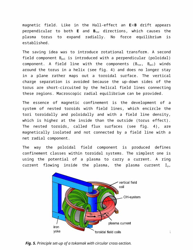
The way the poloidal field component is produced defines confinement classes within toroidal systems. The simplest one is using the potential of a plasma to carry a current. A ring current flowing inside the plasma, the plasma current Ip, produces the poloidal field component Bpol. As the temperature of the electrons, defining the electrical conductivity of a plasma, is highest in the plasma core, the current density profile j(r) peaks there. Such systems are called tokamaks [6] and are a Russian invention of the 50ies of last century8. Fig. 5 shows the principal set-up of a tokamak. The major attraction of the tokamak is that Ip can be produced by a pulsed transformer whereas the plasma ring surrounding a central primary coil acts as secondary winding. In tokamaks, the ratio of Btor/Bpol >1. Another concept with plasma currents is the reversed field pinch (RFP) with Btor/Bpol ~1 [7]. Tokamaks and RFPs belong to the category of internal confinement systems because part of the confining magnetic field is produced by currents flowing inside the plasma.
An alternative way is to produce the poloidal field like the toroidal one - by external coils. In this case, the coils have to wind helically around the torus. The field composition reminds of a multipole arrangement with coils being first helically twisted and then bent to a torus. Depending on the current direction inside the helical coils – unipolar or bi-polar – we speak of heliotrons/torsatrons or of stellarators. Both belong to the class of helical systems. Stellarators are a US invention of the 50ies. Fig. 6 shows a sketch of a classical l=2 stellarator with helical coils. Helical systems belong to the category of external confinement.
8 The acronym Tokamak means: toroidal chamber with magnetic coils.15
Fig. 5. Principle set-up of a tokamak with circular cross-section.

Toroidal systems share common descriptors. In the simplest case with circular poloidal cross-section the torus geometry is defined by major radius R and minor radius a (see fig. 4). The ratio A = R/a is called aspect ratio. The rotational transformof a flux surface is defined by the winding law of the field lines given by /2 = A Bpol/Btor. RFPs have a largerthan tokamaks. In case of helical systems, Bpol is determined in a complex form by the external helical coils system, which is described by the number of coils e.g. 3 heliotron coils with unidirectional current yielding an l=3 heliotron. In this case the poloidal cross-section has the shape of a triangle. In case of a stellarator with 4 helical coils and bi-polar currents, we have 2 pairs of coils and an l=2 stellarator (see 6). Its poloidal cross-section is elliptical. Another important stellarator descriptor is the coil pitch. The coil winding laws are such that the coils ultimately close. The field pattern of helical systems is periodic in toroidal direction. The toroidal periods can be m=5 (Wendelstein 7-A, Germany [30]) or in case of tight windings e.g. m=10 (Large Helical Device, LHD, Japan [20]).
Simple tokamaks have a circular cross-section. Equilibria at higher plasma currents are possible when the cross-section is elongated or even has triangular shape. Modern tokamaks benefit from the higher current
- reaching higher plasma density - a critical ignition and burn parameter (see sect. 4), - higher stability in terms of the ratio of = <pkin>/(B2/20), average kinetic pressure to
magnetic field pressure, and - better confinement, expressed by a larger energy confinement time E.
We understand the importance of the plasma core in providing conditions for a high fusion yield. Also the surface of the confinement system, the so called last closed
16
Fig. 6. Principle set-up of a classical l=2 stellarator with helical coils.

magnetic surface, is of utmost importance. The plasma surface is defined by a separatrix (see fig. 4), which separates (therefore the name) the nested flux surfaces inside from a belt of open field lines at the outside in the so-called scrape-off-layer (SOL). The separatrix if formed by a null in the poloidal field B pol, which itself is determined by the superposition of the poloidal field of the plasma current with that of additional external poloidal field coils. An X-point (see fig. 4) is formed where the field is exclusively the toroidal one. The rotational transform of the separatrix is 0. Outside the separatrix, the field lines move around the plasma, are diverted at the X-point, separated from the main plasma and finally guided into a separate chamber, the divertor chamber (see fig. 4). This is the basic geometry for exhaust and for the establishment of the plasma wall interaction inside the divertor chamber as also foreseen for ITER and a future fusion reactor. The neutralization of the plasma happens and the transfer of the -particle power (apart from the fraction, which is radiated off at the plasma periphery, the SOL and divertor plasma) occurs at target plates located inside the divertor chamber. The target plates have to stand high heat fluxes in the range of 10 MW/m2; the divertor chambers are equipped with pumping systems to exhaust He and to control plasma density and composition. Impurities released from the contact zones with the plasma are mostly retained inside the divertor. The magnetics of divertors is still an area of R&D with new concepts emerging, dubbed Super-X [8] or snow-flake divertor [9].
Also modern stellarators are not simply set-up by coils described by l and m. Like in the tokamak case, shaping is essential to improve and optimize plasma performance. The most effective optimization is possible within the concept of multi-helicity stellarators with a mix of poloidal and toroidal l and m parameters. In this case the plasma cross-section varies toroidally changing cross-section according to the dominant local field Fourier coefficients. The benefit of such a configurational complexity is described in sect. 9.2. It is difficult to realize multi-helicity stellarators by employing helical coils. Instead of separate sets of toroidal and helical coils, so called modular coils are used. These are basically individual toroidal coils, which, however, are not planar like in the case of a tokamak rather show specifically shaped lateral excursions (see fig. 12), who line up such that a poloidal field component is generated. Unlike the tokamak, the stellarator does not need additional coils to produce a separatrix. Stellarators are limited by a separatrix as a natural feature of their magnetic system.
Both lines, internal and external confinement, are pursued because of complementary properties. The plasma current of tokamaks represents a strong ohmic heating source for the plasma, POH, and one can easily reach temperatures around a keV with it. For RFPs the ohmic heating alone may be sufficient to reach reactor conditions. An important advantage of the tokamak is its continuous toroidal symmetry. Hence, the toroidal angular coordinate is an ignorable one; the consequence is that the associated canonical momentum p is a conserved quantity. As we will see below, this aspect enters the quality of magnetic confinement.
17
We have discussed the role of field inhomogeneities in case of the mirror device. Toroidal systems also carry a mirror because of the radial field gradient. In a tokamak, there are two classes of particles like in the mirror device. Particles with small v /v are affected in their orbit by the increasing magnetic field on their way along the field line toward the inner sector of the torus. If v/v is too small the particles are reflected at Bmax. In this case, they do not freely propagate along the field line and do not experience the full rotational transform, rather they stay at the outside between two mirror points. They are dubbed “trapped particles”. Their drift in the field gradient is not fully compensated and they show, therefore, deviations from the flux surfaces much larger than the Larmor radius. Their movement is periodic, however, and they are confined. This is also ensured for the other class of particles. They move freely from the torus outside to the inside and back. They are called free particles. Their deviation from the flux surface is small but modified by the curvature of the toroidal field system. The strength of the axi-symmetric tokamak is that particles move along periodic orbits with finite deviations from the flux surface.
The negative side of the tokamak is the need to inductively produce the current like in a large transformer with the plasma ring representing the secondary winding. This limits the plasma pulses. At the end – maybe even after a few hours - the primary transformer system is exhausted and has to be recharged within minutes. It is not clear yet whether a pulsed system with these features qualifies for a power plant in the GWel power range. Therefore, non-inductive current drive techniques are developed using the injection of fast particles or directed e.m. waves. The optimisation of external current-drive for tokamaks is a dynamic R&D field.
Other problems emerging from the presence of a strong plasma current are current driven instabilities. In a tokamak, the existence of an equilibrium is intimately connected with the existence of the plasma itself and its quality to carry a current. There are non-linear relations between equilibrium, transport and stability properties, which allow the development of instabilities causing degradation up to the limit of self-destruction of the plasma in a disruption. In case of a reactor, 20 MA or so may thus be switched-off within a fraction of a second. The electro-mechanical dynamics of such a perturbation leads to high voltages or high currents, Iind, induced in structural components leading to strong IindB forces which have to be safely handled.
An interesting aspect of the RFP is that the current is maintained self-consistently by a dynamo process inside the plasma. Strong magnetic turbulence adds up in a coherent way to produce a plasma flow with velocity vdyn, which induces an electric field Edyn = vdynB, which itself drives poloidal current giving rise to most of the core toroidal magnetic field. The catch of this simple concept is the lack of nested flux surfaces being replaced by a rather chaotic field pattern caused by a high magnetic turbulence level allowing only low confinement. High transport levels are the major concern for RFPs.
18

Though the programmatic validity of the RFP might be questioned, its plasma has rich physics resembling in some aspects those observed in stellar plasmas allowing to study astrophysics phenomena in the laboratory. It has also interesting aspects of self-organisation of thermodynamically open systems, which we will present in sect. 7.
The plasma geometry of stellarators is invariably 3-dimensional. No equilibrium can be constructed with continuous symmetry in the current-free case when rotB = 0. In addition to the toroidal curvature effect helical systems show a further field inhomogeneity, which is introduced by the helical coils (or by the aligned lateral coil excursions of modular coils). The field beneath the helical coils is larger than the one between these coils. As a consequence, there is a third class of particles complementing the free and toroidally trapped ones – the helically trapped particles. These particles are highly localized in phase space, benefit only little from the confining effect of rotational transform with the consequence of a net radial drift out of the system. They lead to intolerable losses under reactor conditions.
A more fundamental treatment of particle confinement starts from the 3-dimensional field geometry of a helical system, the lack of continuous symmetry replaced by discrete toroidal periodicity. In such a case there is no toroidal (tokamak, RFP), poloidal (mirror device) or helical (linear stellarator) symmetry established as in principle possible for magnetic confinement. The corollary of the lack of symmetry is that no component of the canonical angular momentum is conserved and that collisionless losses in phase space occur. As this “loss-cone” is continuously filled by collisions, helical systems have difficulties to meet the ignition and burn conditions unless the problem with the lack of symmetry is removed. This is the story of the so called quasi-symmetric stellarators as described in sect. 9.2.
7. Characteristics of high-temperature fusion plasmas
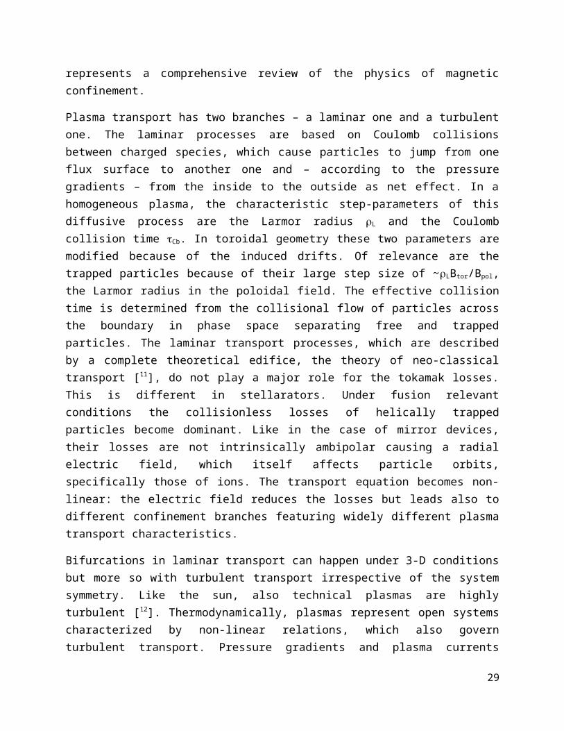
A fusion plasma has to fulfil many requirements - equilibrium, stability, good confinement, plasma purity, and other qualities. This requires a rigorous strategy of optimisation. It involves high-level physics issues like the understanding of turbulent plasma transport and its “taming”, but also technical issues like the qualification of compound structures able to withstand the contact with the plasma. Here we will suffice ourselves by only discussing one aspect, plasma transport and resulting confinement, as it is the most critical issue and possibly the most interesting one from the scientific point of view. Ref. [10] represents a comprehensive review of the physics of magnetic confinement.
Plasma transport has two branches – a laminar one and a turbulent one. The laminar processes are based on Coulomb collisions between charged species, which cause particles to jump from one flux surface to another one and – according to the pressure gradients – from the inside to the outside as net effect. In a homogeneous plasma, the
19

characteristic step-parameters of this diffusive process are the Larmor radius L and the Coulomb collision time Cb. In toroidal geometry these two parameters are modified because of the induced drifts. Of relevance are the trapped particles because of their large step size of ~LBtor/Bpol, the Larmor radius in the poloidal field. The effective collision time is determined from the collisional flow of particles across the boundary in phase space separating free and trapped particles. The laminar transport processes, which are described by a complete theoretical edifice, the theory of neo-classical transport [11], do not play a major role for the tokamak losses. This is different in stellarators. Under fusion relevant conditions the collisionless losses of helically trapped particles become dominant. Like in the case of mirror devices, their losses are not intrinsically ambipolar causing a radial electric field, which itself affects particle orbits, specifically those of ions. The transport equation becomes non-linear: the electric field reduces the losses but leads also to different confinement branches featuring widely different plasma transport characteristics.
Bifurcations in laminar transport can happen under 3-D conditions but more so with turbulent transport irrespective of the system symmetry. Like the sun, also technical plasmas are highly turbulent [12]. Thermodynamically, plasmas represent open systems characterized by non-linear relations, which also govern turbulent transport. Pressure gradients and plasma currents represent the free energy, which drive plasma turbulence. There are de-stabilizing properties like plasma resistivity, or geometrical aspects like the collinearity of pressure and field gradients at the outer half-sector of the torus, or so-called rational flux surfaces where a field line does not ergodically map out the flux surface rather closes upon itself after a number of toroidal and poloidal circulations. Resistivity decouples the conducting medium (the plasma) from the magnetic field; the diamagnetic nature of the magnetized plasma causes it to move outward into areas of low magnetic field. This tendency is supported by the pressure gradient at the torus outside (and opposed by the one at the inside). In the third case the topology of a global instability as an Eigenmode of the bound geometry coincides with the topology of the rational field line closing upon itself. Under these circumstances a mode or instability does not have to invest energy for the distortion of the field topology and can grow with less prohibition.
The transport relevant turbulence scales with the Larmor radius. The non-linear relations between stabilizing and de-stabilizing contributions give rise to onset conditions and define critical gradients for temperature and pressure. If e.g. the temperature gradient grows beyond a critical threshold value, the level of turbulence rises strongly. Formally, the diffusivities depend themselves on the driving force gradient. Therefore, gradients are clamped to the critical ones.
Here we can understand why fusion requires the size already of a reactor to demonstrate its scientific feasibility. In order to meet the high temperature of 20 keV in
20
the plasma core ensuring a high fusion yield, steep gradients are necessary. Those are, however, governed by critical onset-conditions and limited to critical values. The situation is reminiscent of a sand pile. In the effort to increase its height, critical gradients send excess sand in little avalanches to the base of the pile. Only by broadening the base, the peak can be raised obeying the overriding critical condition. In principle, the same is observed in fusion plasmas. In order to meet the core conditions, the volume has to be increased leaving fixed the normalized temperature gradients T/T. Thus, the plasma volume increases and more fusion power is produced with the upshot that fusion can only be demonstrated at the power level of a few 100 MW.
Important is therefore to overcome the conditions leading to profile similarity and to improve confinement. This would allow realising compact and economic systems. Here, a characteristic feature of plasmas comes to rescue, which emerges from its nature as open system, operated far from thermodynamic equilibrium viz. to self-organise. We demonstrate self-organisation in space first by a most simple plasma arrangement - a diode, which is operated with an ac voltage. In order to prevent the formation of an arc, the circular electrodes are protected by di-electric layers. This arrangement allows quasi-two-dimensional dielectric-barrier discharges. The ac-current density does not
21
Fig. 7. Examples of current density distributions of dielectrically suppressed diode discharges. Starting from top/left, a hexagonal pattern, a pattern with periodic stripes, a rotating spiral pattern and a case with bright filaments is shown. These data are obtained by the Research Group Purwins of the UNI Münster [13] (courtesy, H. Purwins).

develop homogeneously across the electrodes rather organizes itself in patterns, which depend on the diode current as control parameter. Fig. 7 shows examples of such patterns [13]. This phenomenon is not unique to plasmas rather a universal phenomenon described by reaction-diffusion theory in the frame of non-equilibrium thermodynamics
[14].
An interesting spontaneous transition into a state with better confinement is observed in RFPs. Under normal conditions strong multi-helicity magnetic turbulence governs transport and confinement. The turbulence level is large enough to ergodize the magnetic field within the confinement zone. If the system is driven hard e.g. by increasing the plasma current, it suddenly transits into a regime with a lower turbulence level. Spontaneously, in the core, the ergodized field is replaced by nested flux surfaces adopting a quasi-single-helicity (QHS) equilibrium. Fig. 8, left, exemplifies such a case. The temperature in this zone shows a distinct increase. The plasma self-heals a defect improving confinement thereby. Fig. 8, right, shows this configurational change with an
22
Fig. 8. Left: Shown is the development of a single-helicity state in the plasma core of a RFP. Top right: electron temperature with a peak in the radial range of the helical equilibrium. Bottom right: poloidal cross-section with nested flux surfaces and chaotic field lines closer to the edge (courtesy, Consortia RFX).

island in the poloidal cross-section containing nested flux-surfaces giving rise to the benefit of a distinct local increase in temperature [15].
Also in tokamaks and stellarators, bifurcations into regimes with higher confinement are observed, which are of programmatic relevance and allow realizing the fusion conditions under simpler and more realistic conditions. Fig. 9 shows the transition from the L-regime, the low confinement regime, to the H-mode, its high-confinement counterpart [16]. The example is taken from ASDEX-Upgrade tokamak. Also in this case, the transition is a threshold process, which requires a stronger drive developing after surpassing a heating power threshold. The transition occurs as soon as NBI heating has been added (see fig. 9a). The 2-dimensional turbulence at the plasma edge changes its
23
Fig. 9. Plotted are different plasma traces from ASDEX-Upgrade tokamak in a time window from 1.3 to 1.6 sec during a discharge with auxiliary heating (NBI: beam heating; ECRH: electron cyclotron heating) with an H-transition (vertical lines). At about 1.425 s, the discharge transits into a period with limit-cycle oscillations; the final H-transition occurs at 1.44 s (dashed line). Fig. 9 a) plots the energy content together with the power of the two heating methods; fig. 9 b) plots frequency and amplitude (colour coding; log. scale) of the turbulence; fig. 9 c) shows the poloidal plasma rotation for two normalised radii (=r/a). Poloidal rotation increases strongly at the plasma edge, about 1 cm inside the separatrix (courtesy, ASDEX-Upgrade team).

dynamic behaviour (see fig. 9b) whereas the spectral content condenses toward large scales limited only by the minor plasma radius: the interaction of turbulent eddies sum up to a coherent poloidal flow field (see fig. 9c). The sheared flow now acts back onto its driving agent and tears apart - de-correlates - the turbulent eddies. The turbulence is strongly reduced and steep gradients develop at the plasma edge forming – what is called - a transport barrier. When the turbulence is suppressed, the steep gradients for their part are maintained by equilibrium conditions where the steep ion pressure gradient is balanced by a negative radial electric field, which itself is equivalent to a strong and sheared poloidal flow. The state of low-turbulence is preserved. The turbulence quench acts as a trigger mechanism to a state with low turbulence and improved confinement. The prospects and expectations of ITER are based on H-mode confinement qualities. The generation of flows in the interaction with 2-D turbulence is reminiscent of the mechanisms, which give rise to the belts of the planets Jupiter and Saturn and which play a role in atmospheric and oceanic flows.
The potential of self-organisation is largest in RFPs because both confining fields are generated in a self-consistent manner. The stellarator is the opposite, because both fields are produced from the outside under full control. There is an interesting parallelism between the development of the QSH-state of RFPs and the H-mode. Both systems have to be driven hard from the outside. The free energy has to be increased in one case by the current, in the other case by the plasma pressure. In both cases turbulence is reduced in selected regions – in the core or at the edge, respectively. In both cases, the coherent interaction of turbulence gives rise to plasma flows. A transient process leads to a new equilibrium situation where the essential electric field is maintained either by the helical plasma deformation or the increased ion pressure.
8. Status of fusion energy development
Fusion research was started worldwide after world-war II. The EU fusion programme is jointly coordinated by the Euratom contract, which provided the legal basis and the means to build the presently largest and most relevant fusion device, the Joint European Torus, JET, a tokamak, operated in UK close to Oxford. This device is closest to the ignition conditions. In the last decade, the Asian fusion programme has made impressive progress with modern tokamaks in Korea (KSTAR [17]), China (EAST [18]), India (SST-1 [19]). Japan has a long tradition in fusion development and houses the largest helical system at present, LHD, a heliotron [20]. Japan is now constructing a large tokamak, JT-60 SA [21]. All Asian tokamaks are realised with superconducting coils and address the critical and not yet solved problem of steady-state operation, specifically critical for tokamaks owing to their intrinsically pulsed nature. Helical systems are operated in Australia, Germany, Japan, Spain, Ukraine, and the USA. RFPs are operated at many places at the scale of university experiments. The largest devices operate in Italy (RFX [22]) and USA (MST [23]).
24
In separate experiments, fusion has already achieved the necessary temperature and density. Temperatures of 40 keV can be produced in a routine fashion basically by pressing a knob. Densities have been achieved a factor of ~10 above the required one. The critical parameter is E, where a factor of 4 is missing for reaching ignition. It is a major effort of the world-wide fusion programme to improve confinement quality beyond the one achieved with the H-mode. Recently, it was shown that transport barriers, as
observed in the H-mode at the edge, can also be produced additionally in the core region in the form of internal transport barriers [24]. Intense fusion research still pays off!
The US experiment TFTR and JET have carried out DT experiments without any technical problems. Of course, the tritium consumption is in the range of grams and not kilograms as necessary in case of a reactor. -particle heating has been demonstrated. Most importantly, JET has demonstrated in a short pulse a fusion power of 16.1 MW in DT experiments in the H-mode equivalent to a power amplification factor Q = P fus/Pext ~ 0.65.
The fusion community was able to support unanimously one concept for the first fusion test reactor, ITER. This device is based on the accumulated word-wide knowledge with a strongly shaped tokamak plasma incorporating a divertor for exhaust. The first-wall materials are in agreement with the best knowledge available at present.
25
Fig. 10. Multi-machine thermal energy confinement time E,thexp against the scaling
results of the 98(y.2) ITER scaling. The expected ITER confinement time is also shown.

The international efforts of fusion research are best demonstrated by the joint data base, which provides the scaling of the energy confinement time E defining the operation point of ITER. As E is determined by turbulent processes a precise prediction of the ITER E
value is still not possible though the basic mechanisms are understood and the equations and the formal structure for turbulence modelling developed. Its multi-parameter dependence has to be identified by many experimental results subject to a rigorous statistical regression analysis. The outcome of such a study is shown in fig. 10. An experimental E value depends on many parameters, plasma current Ip, toroidal field Btor, heating power P, density n, isotopic mass M and the key geometry parameters, major radius, R, elongation, ,and triangularity of the plasma cross-section, :
EITER(s) = 0.0365 Ip
0.97(MA) B 0.08(T) P -0.63(MW) n 0.41(1020 m-3) M 0.20 R 1.93(m) 0.23 0.67
The expected E value of ITER is also shown (3.7 sec). It is in agreement with the objectives of ITER and defines several crucial parameters of its design.
Stellarators can operate at higher density than tokamaks, which is an advantage for high power divertor operation. They show similar parameters as tokamaks of similar size and field. They do, however, not yet reach the high temperatures and confinement times as the large tokamaks because of the smaller scales of the present-day helical systems.
26
Fig. 11. Computer drawing of the International Tokamak Experimental Reactor, ITER.

9. The next development steps
9.1 ITER
ITER, shown as a computer drawing in fig. 11, will be the first fusion reactor producing fusion energy aiming at a power gain Q = 10. The technical specification of ITER is given in box 1. ITER has major physics issues to explore and to clarify, which necessitate a burning plasma state. The most important ones are (1) the confinement characteristics with dominant self-heating, (2) burn control and helium-exhaust, and (3) plasma stability in the presence of a fast ion component, the -particles. Crucial are also the properties of helium transport from the core to the edge and the safe removal of He within the divertor. Only a helium concentration of 2 % is tolerable in the reactive core (see fig. 3). The He-fluxes have a convective and a diffusive component. It is expected, but not ensured that the convective part will move He ions to the outside. The -particle pressure also represents a contribution to the free energy with the potential to drive instabilities. In this case, Alfven waves could be induced by a velocity resonance within the spectrum of slowing-down -particles, which could act back onto the driving mechanism and reduce the confinement of energetic particles needed for plasma heating. Another crucial area of exploration with ITER is external current drive to prepare the conditions for steady-state tokamak operation. This effort combines suitable techniques with judiciously tailored plasmas, which maximise internal currents (bootstrap current) minimizing thus the needs for external contributions.
There is a large field of technological contributions expected from ITER. As only real projects solve practical problems and provide the necessary technologies, ITER plays a unique role in fusion technology also. ITER will demonstrate the use of superconductivity in the harsh environment of fusion, the viability of remote handling techniques for the complex assembly and maintenance tasks inside the plasma vessel and it will develop ambitious external heating and current drive concepts like the injection of high-energy hydrogen atoms at 1 MeV energy and in the 100 MW power range.Critical issues are the exhausted -power
Box 1: ITERThe International Thermonuclear Experimental Reactor, ITER, is based on the tokamak concept. It is the first fusion reactor to produce a large amount of fusion power (500 MW) on the basis of dominant self-heating by 100 MW of -particles. ITER will be a fully licensed nuclear device. The magnetic field on axis will be 5.3 T produced by superconducting coils using Nb3Sn. The current of ITER will be up to 15 MA. The geometry of ITER is: major radius R0 = 6.2 m; minor radius a = 2 m; elongation = 1.7; triangularity = 0.33. ITER will be equipped with a divertor. External heating for ITER will employ neutral beam heating (33 MW) and both electron and ion cyclotron heating (20 MW each). The formal objectives of ITER are a fusion amplification factor Q ≥ 10 with an average neutron wall load of ≥ 0.5 MW/m2. The pulse length is limited to 500 sec. In another scenario, quasi-steady state will be demonstrated, however under the reduced requirements of Q ~ 5. ITER will start operation around 2020.
handling at a level of 15 MW/m2 and the demonstration of tritium production using test blankets in a form, which allows clear modelling predictions for those used in DEMO and a later power reactor.
27

9.2 Wendelstein 7-X and the HELIAS reactor
As we have seen, stellarators need confinement optimisation. The most rigorous form led to the concept, which underlies the Wendelstein 7-X (W7-X) project to be realised in Greifswald, Germany, which is presently (2012) in the assembly phase (see fig. 12). The design parameters of W7-X are given in box 2. The theoretical background of the optimisation is (1) that the deviation of particles from the flux surface as well as
Box 2: Wendelstein 7-XWendelstein 7-X (W7-X) is a multi-helicity stellarator with optimized properties following the quasi-isodynamicity concept. Its 50 modular coils are fabricated from NbTi superconducting materials with 3 T maximal field on axis. Heating and cooling of the system will allow 30 min pulses. Major radius of the device is 5.5 m. The aspect ratio is 10. The major heating system is a steady-state electron cyclotron system of nominal 10 MW power at 140 GHz. Neutral injection and ion-cyclotron heating are in preparation. For exhaust, W7-X is equipped with an island divertor. The device is presently assembled in IPP branch Greifswald; start of operation is scheduled for 2014.
equilibrium and stability properties depend on the variation of the magnetic field strength |B| in the flux surface [25] and (2) that |B| can be made 2-dimensional in an otherwise 3-dimensional toroidal geometry [26] as it is given fact for external confinement. Systems with these properties are called quasi-symmetric systems and meanwhile several smaller stellarators are built and operated based on these concepts (HSX in Wisconsin [27], Heliotron J in Kyoto [28]). The design of W7-X follows the quasi-isodynamic principle. In an isodynamic system [29] all flows of particles, heat and charges would ideally occur in a flux surface without radial component. Such a system cannot be realised in the
28
Fig. 12. Photo into the experimental hall of Wendelstein 7-X (status Dec. 2011).
frame of toroidal confinement. Quasi-isodynamicity, a viable approximation, foresees rigid equilibrium and stability toward high plasma pressure and good confinement for thermal and energetic particles (-particles) avoiding the helical ripple losses as described in sect. 6. One optimisation feature is the utilisation of the mirror effect. The toroidal periodicity of W7-X corresponds to a pentagon. Straight sectors are connected by corners. The toroidal curvature is therefore localised to the corners. In order to minimise the drift losses in the zones of field inhomogeneity, the field strength IBI is increased in the corners. W7-X resembles a system of linked mirrors. The most critical particles to drift off the system, those with a large v/v, are expelled from the sectors with curvature. The complete and rigorous optimisation is still not verified. Some of the basic physics qualities have, however, already been tested in the smaller and partially optimised stellarator device W7-AS [30]. These favourable properties – if they become reality - are on top of the intrinsic stellarator characteristics - steady state operation free of current driven instabilities. W 7-X, being a superconducting device, is supposed to demonstrate these features for pulses up to 30 min.
Stellarator reactor studies have the main emphasis on stellarator-specific aspects such as the coil system and the complex 3-D geometry of blanket and neutron shield. They are basically extrapolations of the present concepts, in case of W7-X it is the HELIAS reactor concept [31]. The design is dictated by two criteria: at first the size must be large enough to accommodate blanket and shield between plasma and coils and secondly the confinement time, which roughly grows with the plasma volume, must be large enough to ensure ignition and self-sustained burn. Not explored in much details yet are the necessary properties subsumed under the term RAMI – reliability, availability, maintainability and inspectability. The 3-D nature of stellarators will complicate the technical realisation of the RAMI criteria. Otherwise, stellarators have to demonstrate the same qualities as foreseen for ITER and described in the previous chapter. Of course, also stellarators will benefit tremendously from the additional physics and the technology provided by ITER. Whether an intermediate step will be necessary in the stellarator reactor evolution like a “stellarator ITER” is probable but needs to be seen.
A future stellarator reactor will not need a current drive system. About 200 MW current drive power are required for a steady-state tokamak reactor. The plant electricity consumption and the recycling power are large for a typical electrical efficiency of 0.4. This could increase the cost of electricity by 25% [32].
9.3 DEMO
The DEMO will be an electricity producing fusion reactor prototype, which will deliver about 1 GW electric power steady-state or quasi-steady state. It will be slightly larger than ITER. Specifically, it will operate at higher density (P fus, being a binary process, scales with n2) and will require somewhat higher confinement and stability margins. These topics are on the agenda of the ITER research programme. ITER will also play an
29

important role for DEMO in the field of licensing. This is a totally new area, which will be exercised for the first time with the nuclear safety authorities of France.
The DEMO could be a tokamak or a stellarator. It could also be that the global energy demand is so critical in one or two decades from now that more means are provided than is presently the case for energy research so that fusion R&D could continue on a much broader basis.
10. Technical issues
10.1 Tritium production
The critical quality of the breeding blanket is the tritium breeding ratio TBR. For each triton burnt in the fusion process a new one has to be formed. Because of unavoidable losses (decay in storage, initial feeding for other fusion reactors, spurious tritium inventories in the exhaust and recycling system), TBR has to be > 1 to achieve supply self-sufficiency. This quality depends on plasma physics properties like the burn-up fraction (fusion reaction rate/tritium fuelling rate) and design aspects of the blanket, the nuclear processes inside the materials used, the way a 14 MeV neutron slows down causing interactions with lithium governed by the cross-sections of fig. 2 till it is finally absorbed or lost. The relevance of process (5) is the high cross-section down to the lowest neutron energies. In the 6Li-reaction, each n has the chance to generate a tritium nucleus. In addition, this process contributes with nearly 30% to the fusion energy yield. The importance of process (6) is the n-multiplication, which is possible for neutrons with an energy above the threshold of 2.5 MeV (see cross-section in fig. 2).
A fusion reactor needs an initial supply of tritium from an external source to start operation till it reaches tritium-self-sustainment. The external sources are heavy water fission reactors (e.g. the CANDU reactor), which use heavy water for moderation and cooling as they are operated in Canada, India and Korea. The world-wide amount of tritium is determined by the production and mostly the radioactive decay and may eventually rise to 25 kg in 2036 when Canada plans to stop the last of the present CANDU reactors under operation. A fusion power plant will initially require 7 kg tritium to start. The exact value depends on the tritium burn-up fraction, which, however, cannot be predicted with confidence. This shows us that the tritium-availability gives rise to rather critical supply conditions for the later market penetration of fusion power plants at and beyond 2050. At an optimistic breeding ratio of 1.15 a 3 GW thl power station produces 25 kg/y surplus tritium to start other fusion reactors. But also in the future, tritium can and will be produced by other means. Canada, the main tritium supplier at present, plans to build advanced versions of the CANDU reactor type. Thermal reactors also those of the Generation-IV family can breed tritium via the process of eq. 5.
30

In any case, it is urgently necessary that the actual TBR values are confirmed under realistic conditions. Fusion has not yet tested a breeding blanket because a serious test requires a burning plasma supplying 14 MeV neutrons. Pure lithium would have the highest TBR close to 2 but is not considered because of the safety aspects of this alkali-metal and its unfavourable flow conditions as a conducting liquid in the magnetic environment of a fusion device. For ITER, two breeding blankets will be tested in situ, one based on liquid PbLi-eutectic, the other one on solid Li-ceramic with a lower TBR. Both will allow testing the TBR under realistic conditions but the foreseen test blankets will not allow ITER to produce the tritium it actually needs. It has to come from external sources.
At present the expected TBR parameters are based on mock-up experiments and on numerical calculations of the n-transport. The calculations and their benchmark are of utmost importance because blanket designs optimized for a high TBR have to be done computationally. Fig. 13 shows the volume T-production in a LiAlPb blanket mock-up as a function of the penetration depth of initially 14 MeV neutrons from an accelerator [33]. The overall rise of the curve depicts the increasing role of 6Li when neutrons slow down. There is good agreement with calculations. Some discrepancies come about by the lack
31
Fig. 13. Tritium production in the LiAlPb mock-up experiment for the source fluence of 2.15 × 10¹³ neutrons measured with LiF-TLD, which were calibrated with a Li glass scintillator, and tritium production calculated with MCNPX for the same neutron source fluence. The x-axis shows the distance from the center of the detector channel to one end of the channel [33]. (Courtesy, H. Freiesleben and Elsevier publisher).

of detailed knowledge in the cross-sections of relevant nuclear processes. In order to increase the tritium-yield, neutron-multipliers can be used, which are based on the (n, 2n) reactions with thresholds lower than 14 MeV. Candidates are beryllium (9Be + n 24He + 2n) and lead (208Pb + n 207Pb + 2n), which is already part of the LiPb blanket eutectic. Pb has the higher cross-section (see fig. 2). The idea to enrich natural Li with 6Li because of its high cross-section specifically for thermal n-energies has to be traded off against the virtue of process (2) to increase the number of neutrons. A realistic value for the TBR of a fusion blanket meeting all three tasks is about 1.1.
10.2. Fusion materials
A fusion reactor is a technically challenging device. One has to build a system, which allows 150 Mill K in the core and 2 K about two meters away. The maximum magnetic field of the system is ~ 12 T at 1.8 K using Ni3Sn superconducting filaments. The magnetic system energy is in the range of 50 GJ. High neutron fluxes have to be handled in the range of 2-3 MW/m2 causing a degradation of the mechanical and thermo-mechanical properties of fusion materials like ductility, tensile -, fracture -, and creep - strength. The tolerable neutron fluxes are defined in terms of displacements per atom (dpa). The situation of ITER is uncritical with 1-3 dpa. The DEMO and reactor materials have to stand as much as 100-150 dpa9. The corollary is that parts of the blanket have to be replaced after 3-5 years of operation. In addition, (n,) reactions produce helium and (n,p) reactions hydrogen inside the material also leading to equally critical material fatigue. As a consequence of the material degradation, the temperature of the ductile-to-brittle transition (DBTT) moves toward lower values also reducing the thermodynamic efficiency of the system.
A crucial field is the development of low activation material. The usual minorities of stainless steel responsible for selected material properties have to be reduced if they are transmuted into radio-active isotopes. These are predominantly Co, Ni, Nb and Mo. Low activation materials based on ferritic-martensitic steels are predominantly developed in Europe and Japan. In case of Eurofer [34], the less critical minorities are Cr, W, V and Ta. Structure materials based on Vanadium-alloys or SiC ceramics would be even superior from the waste point of view but they require further development. Such a material selection programme pays off for fusion because the structural materials and not the reaction products determine the radioactive inventory.
ITER can be build by standard technologies and materials e.g. austenitic steels. The material challenges beyond ITER necessitate a material R&D programme. For this purpose a 14 MeV neutron source is required to be able to assess all material consequences of the high transmutation rate of 14 MeV neutrons. This can be realised in the form of a spallation source with a deuterium accelerator and a tritium target or by
9 The production of 0.5 TWh electricity in a fusion reactor gives rise to about 1dpa.32

a neutron source based on thermo-nuclear reactions. IFMIF, the International Fusion Materials Irradiation Facility [35], is presently designed as 14 MeV n-spallation source in the frame of the IAEA by Europe, Japan, Russia and the USA. It could also be a plasma neutron sources based on the spherical tokamak [36] or on a specific version of a mirror machine [37].
10.3. The availability of fusion fuels
3.55 1020 fusion processes per sec yield a fusion power of 1 GW th. Expressed in atomic mass units (u) for easy scaling purposes, this corresponds to 18.7 kg/y. The annual fuel demand is therefore 37.4 kg of deuterium and 56 kg of tritium. Assuming that the majority of T-production occurs via 6Li, which has a cross-section more than 3 orders of magnitude larger than the one of 7Li at low energies (see fig. 2), the annual 6Li consumption is 112 kg, which corresponds to 1.5 tons/y of natural Li. For a TBR of 1.1, we would, on the basis of these simple estimates, need about 20 kg/y of beryllium (9 u) or 400 kg/y of lead (207 u), respectively. The actual consumption is larger and depends on details of the blanket design and plasma operation.
We use the raw-material data compiled in [38] to roughly assess the energy, which can be gained from fusion considering the availability of the materials the fusion process consumes. Sea-water contains about 2.3 1013 tons of deuterium. This is adequate forever, and we do not have to discuss this fuel branch any further. The reserves (resources) of lithium are about 7 (22) Mtons. In the sum, they would deliver about 6 107
TWh10. This compares with 20000 TWh of present world electricity demand. The water on earth would supply a factor of 104 more Li than is known on the earth. The Li-fuel is therefore not a problem of availability rather of workability. For one GW of electricity one has to extract lithium from about 300 ltr water per sec. For the electricity of Germany, this implies the processing of the flow of a small river. To compare with, the river Rhine transports about 2000 m3/s. A corresponding technology to extract lithium from water might indeed be reasonable11.
About 80000 tons of beryllium are expected to be mined on earth. They would allow about 1.5 107 TWh. This material would limit fusion energy to about 700 years at present demand. But Be can be substituted by lead. The lead reserves are about 79 Mtons, the resources 1.5 Gtons providing ~ 1010 TWh electricity.
Structural materials and those for the superconducting coils are not considered here. Also helium, which might get spares if the careless use of it continues, is not considered. The actual materials used to build a fusion reactor will depend on the overall technical progress e.g. on the possible application of high-temperature superconductors.
10 We assume an electricity conversion efficiency of 0.35.11 Even if the Li recovery necessitates the evaporation of the water still a positive energy balance is possible.
33

In summary, lithium is the limiting raw material in fusion. As Li is presently also the material of choice for batteries, the removal of 6Li may have to be considered. 7Li can be used for batteries without performance reduction. The mining of Li from seawater might be feasible. In this case, no practical limitation for the use of fusion energy is expected from the fuel point of view.
11. Safety issues
11.1. Operational safety
In sect. 5 we have already summarised the intrinsic features of fusion, which can be exploited to realise a safe and justifiable energy source. The safety aspects of a fusion reactor are based, in addition, on reactor models and accident scenarios. ITER goes presently through a licensing procedure with a detailed safety analysis and later it will provide practical evidence for many safety issues.
The basic safety features of fusion energy are that the reactor containment cannot be destroyed by an internal accident. The hazards of fire are reduced by using lithium in the blanket in ceramic form. Graphite will not be used inside a reactor to avoid large tritium inventories. In case of a loss of coolant accident (LOCA) only the afterheat in the structural materials has to be considered. Its power density is about a factor of 100 lower than in case of fission. The temperature increase after a LOCA does not reach melting temperatures and it develops slowly reaching a maximum after about a week. The major safety concern is the release of tritium. Tritium decays with a half-life of 12.3 y. It is a -emitter with, as a consequence, low radio-toxicity. Tritium is highly volatile and quickly diluted in nature, in the atmosphere and the soil. Also the human body purifies itself both from gaseous tritium compounds and from tritiated water. A typical time scale is 10 days. The tritium which is embedded into bones is minute but more firmly bound and has to be considered separately e.g. scaled to the radioactivity of natural 40K of > 100 Bq/kg in human bone tissue. What has been described above are fundamental conditions, which ease the consequences of a maximal accident e.g. after an earthquake. In such an event up to one kg of tritium could be released. Under the worst weather conditions, a comparatively small area of ~ km2 has to be evacuated for a short period. In summary, the collateral damage due to the presence of a fusion power plant will be much less than the primary damage through a hypothetically catastrophe, destroying the reactor.
11.2. Fusion waste
Fusion energy causes waste of an amount comparable to that of fission. The radiotoxicity of the waste is, however, totally different because the fission products, plutonium and minor actinides with long half-lifes are missing (see fig. 14). As described above, low-activation structural materials are developed for fusion. Most realistic at present is the expectation that the activated waste produced by fusion will decay
34

typically within 100 y and can again be used thereafter. In case longer-term waste is created, it is a small amount for which shallow geological deposition is sufficient. It is realistic to expect that this fraction can be avoided by the material development as sketched in sect. 10.2.
11.3. Proliferation issues
Fusion involves tritium and the 14 MeV neutrons allow producing fissile material 239Pu and 233U out of 238U and 232Th [39]. Typically within a month several kg of fissile material can be produced, which comes close to the amount needed for an explosive weapon. Tritium itself is used in atomic bombs boosting ignition via fast neutrons. Hydrogen bombs can be built without tritium using lithium-6 deuteride as explosive. Tritium is available and is used in medicine and industry and it is not an IAEA controlled commodity. Tritium proliferation is not an issue for fusion technology.
35
Fig. 14. Decay of radiotoxicity of the waste from fission and fusion reactors. Shown are the cases of a light water reactor without any waste treatment, with the removal of Pu, of minor actinides (MA) and of fission products (FP). These traces and time scales are compared with those of fusion with various structure materials and coolants. (The plot is partially based on data made available by KIT).

The most recent analysis of the proliferation hazards of fusion being used for breeding fissile material is given in ref. [40]. We follow the main arguments provided there:
- fusion power plants are large and can hardly be hidden.
- nuclear materials are not needed in fusion developed as an energy source. Therefore, they can be easily detected in case of an internationally monitored power plant.
- fusion technology is complex. A simpler technique is to utilise fission; in this case, illegal production of fissile material is less probably noticed.
- a fusion breeder needs a large and vulnerable infrastructure. Clandestine fission material production can be stopped by destroying the infrastructure without any nuclear risks – if such a measure should indeed become unavoidable.
11.4. Fusion as neutron source
Up to now, we have discussed fusion as an energy source. But it can also be considered as a powerful neutron source. Whereas a thermal fission reactor delivers ~ 5 10-3 neutrons/MeV for additional use, fusion with n-multiplication produces ~ 10 times more fast n/MeV. Also a spallation neutron source is not able to deliver this quality. Such an n-source might be required for the development of fusion energy e.g. to test and optimize in-vessel components like blanket or heating or diagnostic hardware, to produce and handle tritium and minimize its inventory and its permeation to the outside or for material testing. Non-fusion applications could be in other research field, where neutrons are used or in the production of isotopes for medical purposes. Fusion neutrons also allow transmuting fission waste, specifically the long-lived minor actinides (MA).
The requirements for a fusion n-source - for whatever purpose - are distinctively lower than those of pure fusion. The physics specification of a fusion n-source is less challenging than the one of ITER. Its fusion power is in the range of 100 MW with Q ~ 1; its plasma parameters are close to those achieved in present-day experiments. Also technical and material requirements are alleviated because of the lower neutron flux densities.
A fusion n-source demands a compact built to be economic [36]. Within the tokamak family, a separate branch has been developed in recent years, the spherical tokamak (ST). An ST is characterized by a low aspect ratio A ~ 1.5. It can meet plasma stability requirements for high Ip/Btor values and it allows high plasma pressure (and power density) as p ~ Ip/aBtor for typical operational conditions. The compact geometry and the profile of the released neutrons also ensures good coupling of them into a surrounding blanket containing lithium for tritium production as well as fission waste to be processed.
36

The fast neutrons of a fusion n-source are able to transmute the radioactive waste of fission into stable or short-lived isotopes integrally shortening its decay time and even allowing to change the whole waste processing and disposal strategies (e.g. by realizing waste disposals with access). A general strategy could be to let the fission products with low n-absorption cross-sections decay naturally and process Minor Actinides by a fusion n-source. One obvious advantage of utilizing the fusion process is that no additional waste is produced within the transmutation process and that the neutrons for transmutation are produced independently not requiring the waste itself as n-source. This is a difference to fission.
A 1 GWel light-water reactor produces per operational year typically 25 kg of MAs. Because of the high fission cross-sections of MAs in the fast-n energy range, a fusion neutron source as specified above could transmute these forms of waste for 5 LWRs. The benefits on the decay of radiotoxicity of partitioning and transmutation of fission radwaste are shown in fig. 14. This diagram stresses, however, once more the benefits of clean fusion energy from the waste point of view even after the optimal post-treatment has been granted to fission waste.
12. Road-map to fusion energy - does fusion come too late or will be too expensive?
The scientific efforts to develop controlled nuclear fusion started in the 50ies of the last century. The original hope might have been to develop fusion energy as quickly as fission was realized after the military use had demonstrated the vast energies released thereby. Whereas Fermi could demonstrate the first self-sustained and controlled fission chain reaction December 1942 with the Chicago-Pile-1 at a ~1 W power level and at the safety precautions provided by an (empty) college football stadium, we now know that fusion needs the appropriate confinement, expressed in confinement time E, which can only be realized at large scales. The consequence is that the first test reactor, ITER, is a large and expensive industrial product, which right away produces 500 MW of fusion power. Such a device needs full nuclear licensing and corresponding safety features. The scientific and technical demonstration of fusion can only happen in a device, which is already close to a commercial reactor.
The feature of fusion unknown in the pioneering period was the high level of plasma turbulence, which transports energy from the core to the edge at a high rate spoiling thereby confinement. As a consequence the fusion development strategy necessitates a chain of devices increasing in size approaching in steps the final reactor parameters. Therefore, there are several decades between a decision to realize controlled nuclear fusion and the final outcome of such a decision. In the 70ies, after the first oil crises, the US fusion community predicted 40 years as developing time for fusion following a request of its government. The 40 years have passed by and the fusion reactor is not yet ready. This delay is in people’s memories and one of the jokes on fusion is that it
37

takes always 40 years independent of the date the question on its realisation is posed. This report presents hopefully enough evidence to contradict this view. What is not considered at all is the financial side of the fusion strategy. Of course, the 40-years development prediction had a sound financial basis. But as soon as the oil crises was overcome in the US and world-wide, the budgets for energy research decreased. Fusion did not get much more than about 10% of what had been specified and demanded. Without support, no delivery on time!
The situation now is different from the one in the 70ies. Mankind has grown from 4 to 7 billion people and will further grow. The oil prices strongly fluctuate with a continuous increase in the average prices. The additional aspect is environment and global warming as corollary of anthropogenic CO2 release. The need to develop powerful clean energy sources has strongly increased and has become a global need. The development of inherently safe fission power plants of the Generation-IV family will take decades. The same time frame governs the development of proper storage for electricity of fluctuating renewable sources if storage is based on chemical processes and not pumped water storage, whose scaling to larger capacities is subject to local conditions. It is meanwhile also clear that bio-energy has only a very limited capacity in the range of 5% of the global primary energy consumption.
In the period of the next 40 years, the oil peak will happen with unimaginable consequences on the economic activities of a globalised world. Facing these perils energy research has to be tremendously intensified. Only the results of energy research may be the insurance that 9 billion people on Earth can live in peace. Facing the few options mankind has and the doubts on their potential, acceptability and sustainability, none of the three possibilities may be discarded or delayed.
ITER is scheduled to start operation in 2020. The initial experimental period will be used to develop plasma scenarios with good prospects to meet the overall ITER goals. The DT operation is scheduled for 2027. The step following ITER will be DEMO, the fusion demonstration reactor. It will be a complete reactor, operating steady-state or pulsed, under quasi-steady-state conditions, which should produce electricity and demonstrate also the economic competitiveness of fusion energy.
W7-X will start operation in 2014. The quality of the optimised stellarator concept will enter the discussion on the continuation of the fusion development when ITER has started. In this period, different DEMO concepts can already be pursued and elaborated. A concept decision can be taken later. It could easily be that both lines are rigorously pursued because ITER has successfully met all its goals and with W7-X a convincing steady-state concept has been demonstrated. In case of success, at the beginning of the 30ties, the development of fusion power can be actively placed into national electricity development strategies. In this period, also a clearer picture will exist about the prospects of Generation-IV fission reactors and the CO2-free operation of renewable
38
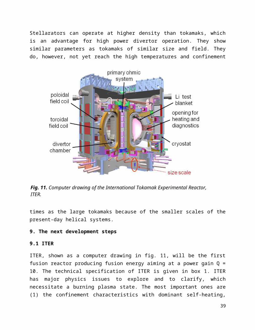
energy sources thanks to the availability of chemical storage systems. With the availability of fusion energy the process of implementation of this technology starts. This period will depend strongly on the availability of tritium to start new reactors. In any case, fusion will not supply mankind with electricity exclusively. Fusion will be an option where ensured base-load power is required and were safe operation of a large electricity sources in critical areas are necessary e.g. within the boundaries of mega-cities.
The cost structure of fusion electricity is determined by large capital costs and largely ignorable fuel costs. Fusion reactors will contribute to the base load and require long full load hours for economic operation. They do not cause external costs because electricity production is CO2-free and the fuel is obtained without leaving back critical environmental damage. The electricity costs will be smaller than the usual state taxes and charges per kWh on electricity are but they are expected to be higher than those from fossil fuels and present nuclear reactors. The details depend, however, on the development of CO2 costs and those for additional fission reactor safety. It is also expected that fusion electricity will be cheaper than photo voltaic electricity. 41
39

References
40

1 [] Garry McCracken, Peter Stott: “Fusion: The Energy of the Universe.” Academic Press; 2nd edition; ISBN-13: 978-0123846563.
2 [] “Fusion Physics”, ed. M. Kikuchi, K. Lackner, M.Q. Tran; IAEA; ISBN 978 92 0 130410 0.
3[] J. D. Lawson, Proc. Phys. Society B, Volume 70 (1957) 6.4[] “Progress in the ITER Physics Basis”, Nucl. Fusion 47 (2007) 1-414.5 []S. Atzeni, J. Meyer-ter-Vehn: „The Physics of Inertial Fusion”, Oxford Science
Publication; ISBN 01985622640.6[] J. Wesson: „Tokamaks.“ Oxford University Press; ISBN 978 0198509227.7[] H.A.B. Bodin, A.A. Newton, Nucl. Fusion 20 (1980) 1255.8[] P.M. Valanju et al., Phys. Plasmas 16 (2009) 056110.9[] D.D. Ryutov et al., Phys. Plasmas 15 (2008) 092501.10[] A. H. Boozer, Rev. Mod. Phys 76 (2005) 1071.11 []R. D. Hazeltine, J. D. Meiss: „ Plasma Confinement”. Dover Books on Physics
Series. ISBN: 978 0486432427.12 [] A. Yoshizawa, S.I. Itoh, K. Itoh: “Plasma and Fluid Turbulence: Theory and
Modelling”, Taylor&Francis, 2002, ISBN 9780750308717.13 [] Purwins H.-G., IEEE Trans. Plasma Sci. 39 (2011) 2112-2113; Special Issue –
Images in Plasma Science 2011.14 [] P. Grindrod: “The Theory and Applications of Reaction Diffusion Equations:
Patterns and Waves”. Oxford Applied Mathematics and Computing Sciences Series; ISBN: 978 018500049.
15[] P. Martin et al., Plasma Phys. Contr. Fusion 49 (2007) A177.16[] F. Wagner, Plasma Phys. Contr. Fusion 49 (2007) B1.17[] G.S. Lee et al., Nucl. Fusion 41 (2001) 1515. 18[] S. Wu et al., Fusion Engineering and Design 82 (2007) 463.19[] Y.C. Saxena et al., Nuclear Fusion 40 (2000) 1069.20[] A. Iiyoshi et al., Nuclear Fusion 39 (1999) 1245.21[] S. Ishida et al., Nuclear Fusion 51 (2011) 094018.22[] G. Rostagni, Fusion Engineering and Design, 4 (1995) 301.23[] S.C. Prager et al., Physics of Fluids B, 2:6 (1990) 1367.24[] R.C. Wolf, Plasma Physics and Contr. Fusion 45 (2003) R1.25[] A.H. Boozer, Phys. Fluids 23 (1980) 904.26[] J. Nührenberg and R. Zille, Phys. Lett. A 129 (1988) 113.27[] F.S.B. Anderson et al., Fusion Technology 27 (1995) 273.28[] T. Obiki et al., Nuclear Fusion 41 (2001) 833.29[] D. Palumbo, Nuovo Cimento B 53 (1968) 507.30[] M. Hirsch et al., Plasma Phys. Contr. Fusion 50 (2008) 053001.31[] Yu. Igitkhanov et al., Fusion Engineering and Design, 81 (2006) 2695.32[] D. Ward, Fusion Science and Technology, 56 (2009) 581.33[] A. Klix et al., Fusion Engineering and Design 83 (2008) 1813.34[] K. Ehrlich, Phil. Trans. R. Soc. Lond. A 357 (1999) 595.35[] A. Moeslang et al., Fusion Engineering and Design 81 (2006) 863.36[] B. Kuteev et al., Nuclear Fusion 51 (2011) 073013.37[] A.V. Burkakov et al., Plasma Phys. Control. Fusion 52 (2010) 124026.

38[] A.M. Bradshaw et al., Fusion Engineering and Design 86 (2010) 2770.39[] W. Manheimer, Jour. Fusion Energy, 23 (2004) 2005.40[] A. Glaser and R.J. Goldston, Nuclear Fusion 52 (2012) 043004.41
Glossary

Alfvén waves Slow hydrodynamic wave in a magnetized plasma where both magnetic field and density propagate together either as compressional or shear wave. The name goes back to Nobel Prize winner Hannes Alfvén, a plasma and astrophysicist.
Anomalous transport
A misnomer for turbulent transport in plasmas.
Becquerel The activity (number of decays per time unit) of a radioactive substance. 1 Bq = 1 decay/s. The name goes back to Nobel Prize winner A. H. Becquerel.
Bifurcation Here a bifurcation is the transition of a non-linear system into a regime with different dynamics. The bifurcation is initiated by the change of a critical parameter or external setting.
Binding energy It is the energy, which has to be spent to split a unit into several parts. Here, it is the energy necessary to split a nucleus into two lower-mass fractions. In the reversed process, the binding energy is released when two nuclei fuse together.
Blanket The fusion blanket surrounds the plasma. It has three tasks – to absorb neutrons and transfer the energy into a cooling media, to breed tritium out of lithium and to shield the superconducting coils from fusion neutrons.
Bootstrap current In this paper we discuss inductive currents. In a plasma with pressure gradients, so called pressure driven currents appear. One of them is a self-generated toroidal current – therefore the name.
Burn-up fraction It is the probability of a tritium atom fuelled into the plasma to fuse with a deuteron before being transported to the plasma edge and lost.
CANDU reactor Is a Canadian fission reactor, which uses heavy water as moderator. This reactor type produces tritium as a by-product.
Coulomb collisions Collisions between charged particles described by the Rutherford cross-section - in integral form in a plasma by the Coulomb cross-section. Assemble properties like collision times and mean-free paths are derived from it.
DEMO DEMO is the fusion demonstration reactor, which is the prototype for commercial reactors. DEMO should demonstrate electricity production at market prices.
Diode A diode here is a parallel-plate electrode arrangement. An ac or dc voltage between the electrodes produces a plasma discharge with a heating current. The electrodes are shielded by a dielectric material to prevent the formation of an arc. This arrangement allows so-called dielectric barrier discharges.
Divertor A divertor is a separate chamber inside the plasma vessel used to exhaust the plasma power and particle flows. It requires a specific magnetic set-up where the plasma is limited by a separatrix and surrounded by a scrape-off layer with open field lines. The field lines are separated from the main plasma by an X-point and guided by specially shaped magnetic fields into the divertor chamber. Here, the field lines cross target plates where the plasma is neutralized on incidence and the plasma power flow transmitted to mechanical structures with cooling channels. Inside the divertor chamber pumps are foreseen for particle and He-ash control.
dpa dpa = displacement per atom caused by impinging neutrons inside blanket and wall.
Eigenmode Eigenmode is a normal mode of a system with fixed boundaries. In this frame, oscillatory movements are possible with characteristic frequencies. The eigenmodes of a toroidal geometry are characterized by the poloidal and toroidal mode numbers m and n.
Energy confinement time
Is the time it takes the plasma to replace its energy content under steady-state conditions. It is a measure of the transport processes inside the plasma.
Eutecticum Is a mixture of materials (e.g. metals) with a specifically low melting temperature, which can be applied for various purposes in the liquid state.
Flux surface This is a term of magnetic confinement. Field lines map out a geometry, which embraces a constant magnetic flux. As a flux surface does not lose flux, the field lines are tangential to it. Toroidal systems comprise nested flux surfaces. The most inner one is a degenerated one, a closed loop – the magnetic axis.
Generation-IV Presently, Gen-II reactors are world-wide in operation. Gen-III or III+