Embed Size (px)
Citation preview
University of WollongongResearch Online
University of Wollongong Thesis Collection University of Wollongong Thesis Collections
2013
Second generation high-temperaturesuperconducting solenoid coils and energy storageHanan Tahir BaiejUniversity of Wollongong
Research Online is the open access institutional repository for theUniversity of Wollongong. For further information contact the UOWLibrary: [email protected]
Recommended CitationBaiej, Hanan Tahir, Second generation high-temperature superconducting solenoid coils and energy storage, Master of Science thesis,Institute for Superconducting and Electronic Materials, University of Wollongong, 2013. http://ro.uow.edu.au/theses/3867
1
Institute for Superconducting and Electronic Materials
Faculty of Engineering
Second Generation High-Temperature Superconducting Solenoid Coils
and Energy Storage
Hanan Tahir Bashir Baiej
“This thesis is presented as part of the requirements for the award of the
Degree of Master of Science
Of the
University of Wollongong
January, 2013
2
Candidate’s Certificate
This is to certify that the work presented in this thesis is original and that it
was carried out by the candidate in the Institute for Superconducting and
Electronic Materials at the University of Wollongong, NSW, Australia, and
has not been submitted elsewhere for any award. Where other sources of
information have been used, they have been acknowledged.
Hanan Baiej
3
Acknowledgements
I am gratefull to all members of the Institute for Superconducting and
Electronic Materials, as well as all members of the School of Physics.
First and foremost I offer my sincerest gratitude to my supervisor, Prof
Alexey Pan, who has supported me throughout my thesis with his patience
and knowledge. I attribute the level of my Master’s degree to his
encouragement and effort and without him this thesis, too, would not have
been completed or written.
Finally, I wish to thank my husband, ALI NURI for his encouragement,
patience and support, as well as my mother, my brothers, and my sisters,
who have always supported me throughout all my studies at university and
encouraged me with their best wishes, I also thank my daughter for bringing
me a great deal of happiness during this work.
4
Table of Contents
Candidate’s certificate………………………………………………………………2
Acknowledgements………………………………………………………………….3
Table of contents…………………………………………………………………….4
Abstract ……………………………………………………………………………..6
List of figures………………………………………………………………………..8
List of tables………………………………………………………………………..10
Chapter 1. Introduction…………………………………………………………….11
1.1 Background…………………………………………………………….11
1.2 Thesis outline…………………………………………………………..15
Chapter 2. Superconductivity, electromagnetism………………………………….18
2.1 Introduction……………………………………………………………18
2.2 Meissner effect………………………………………………………...19
2.3 Vortex lattice or Abrikosov lattice…………………………………….23
2.4 Pinning properties……………………………………………………. 28
Critical currents in high temperature superconductors……………….30
2.5 Applications of superconductor (SCs) and future developments……..31
Chapter 3. Superconducting magnetic energy storage…………………………….34
3.1 Introduction……………………………………………………………34
3.2 Magnets………………………………………………………………..34
Superconducting magnets………………………………………………35
Superconducting coil……………………………………………………35
Power conditioning system (PCS)………………………………………36
5
Refrigerator …………………………………………………………………….36
Charging system…………………………………………………………37
3.3 The modeling of an HTS pancake coil…………………………………39
3.4 Thermal stability in superconducting materials………………………...43
3.5 Applications of SMES………………………………………………….45
3.6 Ongoing SMES development…………………………………………..50
3.7 Comparison of SMES and batteries……………………………………53
3.8 Summary………………………………………………………………..58
Chapter 4. Optimum design of superconducting solenoid coil for a SMES unit….59
4.1 Introduction…………………………………………………………….59
4.2 Calculation results………………………………………………………63
4.3 Field-dependent current performances………………………………….69
4.4 Maximum energy storage……………………………………………….70
Optimization of inner diameter of coil………………………………….76
Optimization of outer diameter of coil………………………………….78
Parameters of one desk lamp……………………………………………..80
4.5 Summary………………………………………………………………..85
Chapter 5. Conclusion……………………………………………………………...87
REFERENCE……………………………………………………………………...89
6
Abstract
One of the most promising applications of superconductors is in Superconducting
Magnetic Energy Storage (SMES) systems, which are becoming the enabling engines for
improving the capacity, efficiency, and reliability of electrical systems. The use of
superconductivity reduces the loss of energy and makes magnetic energy storage systems
more powerful. Superconducting magnetic energy storage systems store energy in a
superconducting coil in the form of a magnetic field. The magnetic field created by the
flow a direct current (DC) through the coil. Superconducting magnetic energy storage
systems have many advantages compared to other energy storage systems: high cyclic
efficiency, fast response time, deep discharge and recharge ability, and a good balance
between power density and energy density. Based on these advantages, superconducting
magnetic energy systems will play an indispensable role in improving power qualities
integration renewable energy sources and energizing transportation systems. This thesis
investigates the application of superconducting pancake coils that are wound using
second-generation (2G) HTS materials in power system and provides an analysis of
superconducting magnetic energy storage system for potential development and
implementation in a range of applications. Specifically, it designs and calculates the
energy storage in an SMES system using HTS thin films.
Second-generation, high temperature superconducting coils have drawn great attention in
recent years, owing to the highly developed fabrication technology for 2G, HTS, and
coated conductors. Their potential operation at relatively high temperature makes them
good candidates for power applications.
7
With the growing availability of “YBCO-based” second-generation high-temperature
superconductor (2G HTS), the fabrication technologies for 2G HTS wires have been
progressing dramatically, with remarkable advancements in the critical current, wire
length, magnetic-field performance, and production throughput and cost.
This study will highlight recent developments in the fabrication of 2G HTS wire and
prototype devices using YBCO-based wire with high field critical currents, as well as
related magnet technology developments, to design a small closed system of
superconducting HTS thin film solenoid coil, through selection of the optimization
parameters for this coil to store large amounts of magnetic energy, and then to link this
system with one of renewable energy sources.
8
List of Figures
Figure Description Page
Figure 2.1 The Meissner effect 20
Figure 2.2 Type I and II superconductor behavior 22
Figure 2.3 Magnetic field and current density around the vortex 25
Figure 2.4 Schematic E-J characteristic for liner flux flow 28
Figure 2.5 Future development of superconductors 32
Figure 3.1 Magnetic field current density in SMES coil 41
Figure 3.2 SMES coil design 42
Figure 3.3 SMES unit applicable for damping system oscillations 46
Figure 3.4 Types of SMES applications for power systems 48
Figure 3.5 Components of existing SMES system 52
Figure 4.1 Solenoid model for analysis 61
Figure 4.2 Calculation inductance of HTS solenoid versus size ration α and β 68
Figure 4.3 Location of maximum flux density Bm in solenoid 70
Figure 4.4 Calculated maximum energy storage of solenoid versus size ration, α 75
9
Figure 4.5 Calculated energy storage versus height H when inner diameter Di and
critical current Ic are constant 78
Figure 4.6 Calculated energy storage versus height H when inner diameter Do and
critical current Ic are constant 80
Figure 4.7 Model of coil using to stored energy for one lamp 82
Figure 4.8 Relationship between β and energy storage 84
10
List of Tables
Table Description Page
Table 3.1 Advantage and disadvantage of SMES and BES 57
Table 4.1 Characteristics of YBCO tapes 65
Table 4.2 Specification of the YBCO coil for the HTS SMES magnet 65
Table 4.3 THS solenoid coil design 81
11
Chapter 1. Introduction:
1.1 Background
Superconductivity is a common property seen in materials that are commonly used in
magnetic field; at low temperatures many metals, alloys, and compounds are found to
show no resistance to flow of an electric current and to exclude magnetic flux
completely, when a superconductor is cooled below its critical temperature. This property
of superconductivity is in fact quantum mechanical, and it is highly pertinent for current
and future power system applications. Therefore, it is important that superconducting
materials play a greater role in the magnetic domain. One of the most promising
applications of superconductors is in Superconducting Magnetic Energy Storage (SMES)
systems, which are becoming the enabling engines for improving the capacity, efficiency,
and reliability of electrical systems. The use of superconductivity reduces the loss of
energy and makes magnetic energy storage systems more powerful. Because no
conversion of energy to other forms is involved in the storing process, their efficiency
can be very high.
Moreover, SMES uses clean and recyclable, non-flammable liquid nitrogen as a cryogen
(or even cryogen-free technologies) to maintain its operating temperature; thus, SMES
has a semi-permanent lifetime and does not cause environmental problems (Tixador et al.
2005).
Superconducting magnetic energy storage systems store energy in a superconducting coil
in the form of a magnetic field. The magnetic field is created by the flow of a direct
12
current (DC) through the coil. Over the past 30 years, SMES technology has become one
of the most active research areas in applied superconductivity, especially since the High
Temperature Superconducting (HTS) materials were discovered in 1986 (Ju Wen et al.
2007). Since this time, research on SMES has been further promoted, and the technology
has progressed significantly. According to Wen et al. (2007), SMES technology
outperforms other energy storage devices and methods because: the current density of an
SMES coil is about 10 to 100 times larger than that of a common coil; it has virtually no
resistive losses; the efficiency of SMES can reach as high as 95 %. It is able to supply
high quantities of energy in time intervals of milliseconds; it can be easily controlled with
well-developed power electronic technology; and it can enhance power system stability
and improve the power quality through active and reactive power compensation and a
good balance between power density and energy density.
Energy storage is used widely in industry to supply energy where the storage of energy
reduces the time and rate mismatch between energy supply and energy demand. Energy
can be generated and stored when the demand is low, and this stored energy can be used
when there is a demand for it. This helps reduce pollution and the cost of
production. Based on these advantages, SMES systems will play an indispensable
role in improving power quality and the integration of renewable energy sources with the
energizing of transportation systems (Dincer et al).
Previously, the magnet for a SMES system was produced from a low temperature
superconducting (LTS) material such as NbTi or Nb3Sn; however, more recently, high
temperature superconducting magnets have been adopted. This is because the HTS
13
superconductors, such as YBa2Cu3O7-x (YBCO) thin film, can show excellent
performance under high magnetic field compared with that of LTS, and improves the
stability of magnets (Park et al. 2007).
This thesis investigates the application of superconducting pancake coils that are wound
using second-generation (2G) HTS materials in power systems and provides an analysis
of superconducting magnetic energy storage systems for potential development and
implementation in a range of applications. Specifically, it designs and calculates the
energy storage in an SMES system using HTS thin films.
Second-generation, high temperature superconducting coils have drawn great attention in
recent years, owing to the highly developed fabrication technology for 2G HTS, and
coated conductors. Their potential operation at relatively high temperature makes them
good candidates for power applications. Since long-length second-generation high
temperature (2G HTS) superconductors have become commercially available, it is now
possible to wind SMES coils from 2G HTS conductors. Two major advantages of the 2G
technology over the first generation 1G HTS wires are the potential for lower cost and the
ability to tailor wire dimensions for specific applications (Weijia Yuan et al. 2010).
Since a superconductor is much more expensive than normal conductors, it is important
that the energy stored in a superconducting coil is maximized; the most suitable
commercially available high-temperature superconductor (HTS) is YBCO tape. The high
critical temperature superconductors enable operation at higher temperature, making the
cryocooling easier, decreasing the cryogenic investment cost, and improving the coil
stability. For a thin tape conductor, a solenoid is a relatively straightforward coil to
14
construct, and another significant advantage of the coated conductors such as YBCO tape
is their possible lower cost. The decrease in the conductor cost is associated with the
reduced cryogenic cost due to the higher operation temperature, which is fundamental for
the SMES to be widely commercialized. Optimization for superconducting solenoid
designs has been studied for decades (Hoon et al. 2005).
With the growing availability of “YBCO-based” second-generation high-temperature
superconductors (2G HTS), the fabrication technologies for 2G HTS wires have been
progressing dramatically, with remarkable advancements in the critical current, wire
length, magnetic-field performance, and production throughput and costs.
This study will highlight recent developments in the fabrication of 2G HTS wire and
prototype devices using YBCO-based wires with high field critical currents as well as
related magnet technology developments. The HTS thin films used in this study are just
one type of the many possible high temperature materials that could be used. YBCO
coated conductors (CC) multifilamentary wires have been proposed for superconducting
power apparatus such as generators, motors, transformers, and magnets. The nature of
thin films makes the design both difficult and expensive, as it is hard to make long CC
tape with high and uniform critical current density using the present processing
techniques, so joint techniques are required to design double pancake coils for
superconducting magnetic energy storage (SMES). They make it possible to not only
reduce power transmission losses significantly and improve power system stability, but
also to alleviate global environmental problems and allow more efficient use of energy
resources (So Noguchi et al. 2003).
15
The aim of this research is to design a small closed system of superconducting HTS thin
film solenoid coil, through selection of the optimization parameters for this coil to store
large amounts of magnetic energy, and then to link this system with one of renewable
energy sources such as the wind or sun. It is necessary to calculate the amount of energy
that can be stored for use in the absence of an energy source, for example during the
night, and whether the amount of energy stored is enough to supply or support one lamp,
house, city, etc. In this study, the necessary energy to be stored is calculated, and this
energy is used to supply or support one desk lamp to work for about 10 hours. This will
be achieved by using the Origin software program and the energy storage equation E =
(½) LI2, where L is the equivalent self-inductance of the superconductor system, and I is
that current flows through the winding, the critical current which requires the calculation
of inductance according to length of the tape, the coil parameters, and the size and nature
of cryocooler, as well as the calculation of the current according to the width and
thickness of the wire, and the critical current density of the wire. In the future, it is
supposed that these applications will be able to provide energy when necessary.
1.2Thesis Outline
This thesis is organized as follows: Chapter 2 discusses superconductivity and
electromagnetism. Section 2.2 provides more detail on the properties of superconductors
in magnetic field, such as zero resistance and the Meissner effect, the latter of which is
one of the most important properties of superconductors. Sections 2.3 and 2.4 describe
and explain the vortex lattice and pinning properties in type II superconductors, and also
describe the critical currents in high temperature superconductors. Section 2.5 discusses
16
applications of superconductivity, such as power system applications and possible future
developments.
Chapter 3 explains the superconducting magnetic energy storage system and other
commonly used materials in real time applications. Section 3.2 introduces the properties
and benefits of using superconducting magnets, then defines the superconducting
magnetic energy storage system, and describes the superconducting coil, power
conditioning systems and refrigerators used in superconducting magnets. It also discusses
thin film, coated conductors wire usage for energy storage and gives more detail on the
properties and application of YBCO, NbTi and MgB2. Section 3.3 discusses the modeling
of the HTS pancake coil. Section 3.4 explains how thermal stability in superconducting
materials is important for their intended performance in magnetic energy storage.
Sections 3.5 and 3.6 describe the applications of SMES that have wide applicability in the
field of electrical power supply devices, and ongoing SMES developments that can
overcome the existing design constraints and enhance the effectiveness and efficiency of
the system. Section 3.7 presents a broader overview on the working of batteries. The
energy storage systems that are commonly used for various applications are further
discussed, out of which SMES and batteries are chosen for comparison.
The results are presented in Chapter 4. This study is focused on the relationship between
the geometrical parameters and the magnetic field, and the design optimization for a
superconducting solenoid coil made of HTS tape for energy storage purposes is
discussed. Section 4.2 describes the design of a coil made for maximum stored energy
and explains the factors that affect this energy. Section 4.3 shows the calculation results
17
and the parameters for the design of a solenoid coil made of HTS tape. Section 4.4 gives
more detail on the parameters that need to be considered while deciding the features of
the optimal design. Section 4.5 presents the results and show the relation between
maximum energy storage and every parameter used to calculate this energy whether these
parameters are constant or variable.
Chapter 5 contains the conclusion of this thesis.
18
Chapter2. Superconductivity, electromagnetism:
2.1 Introduction
In this Chapter, superconductivity will be discussed in relation to the concepts of
superconducting magnets, critical temperature, heat capacity, critical magnetic field,
applications, and superconducting materials. It is evident that superconductivity depends
on the value of the critical temperature (𝑻c); this factor is one of the most important in the
development and deployment of applications.
A perfect superconductor is a material that exhibits two characteristic properties, namely
zero electrical resistance and perfect diamagnetism, when it is cooled below a particular
temperature Tc, called the critical temperature. Below the superconducting transition
temperature, the resistivity of a material is exactly zero. At zero resistance, the material
conducts current perfectly. This is incomprehensible because the flaws and vibrations of
the atoms should cause resistance in the material when the electrons flow through it. In a
superconductor, however, the electrical resistance is equal to zero although the flaws and
vibrations still exist (W. Buckel. 1999). Below Tc, superconductors exhibit perfect
electrical conductivity and also perfect or quite pronounced diamagnetism. Perfect
diamagnetism, the second characteristic property, means that a superconducting material
does not permit an externally applied magnetic field to penetrate into its interior. When
the temperature is reduced to below the critical temperature, the superconductor will push
the field out of itself. It does this by creating surface currents which produces a magnetic
field exactly countering the external field. The superconductor becomes perfectly
diamagnetic, canceling all magnetic flux in its interior. This perfect diamagnetic property
19
is perhaps the most fundamental macroscopic property of a superconductor. Flux
exclusion is due to what is referred to as the Meissner effect (Poole. 2007).
2.2 Meissner effect
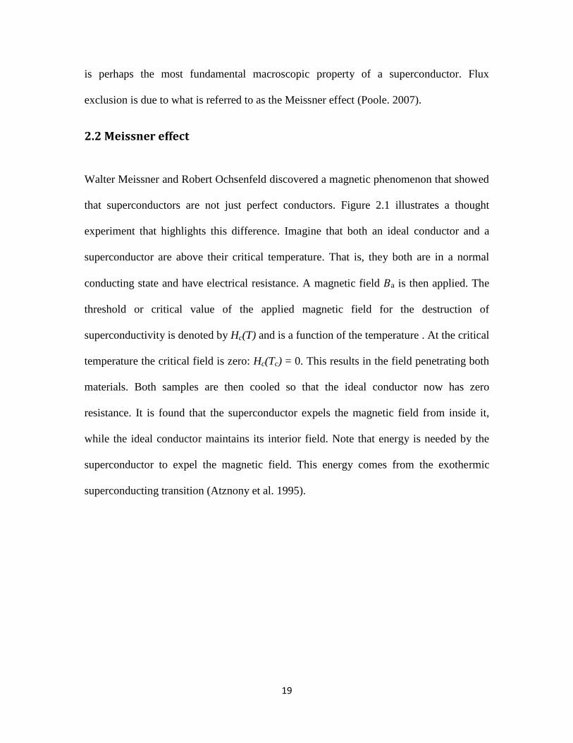
Walter Meissner and Robert Ochsenfeld discovered a magnetic phenomenon that showed
that superconductors are not just perfect conductors. Figure 2.1 illustrates a thought
experiment that highlights this difference. Imagine that both an ideal conductor and a
superconductor are above their critical temperature. That is, they both are in a normal
conducting state and have electrical resistance. A magnetic field 𝐵a is then applied. The
threshold or critical value of the applied magnetic field for the destruction of
superconductivity is denoted by Hc(T) and is a function of the temperature . At the critical
temperature the critical field is zero: Hc(Tc) = 0. This results in the field penetrating both
materials. Both samples are then cooled so that the ideal conductor now has zero
resistance. It is found that the superconductor expels the magnetic field from inside it,
while the ideal conductor maintains its interior field. Note that energy is needed by the
superconductor to expel the magnetic field. This energy comes from the exothermic
superconducting transition (Atznony et al. 1995).
20
(a) B = 0 (b) B = Bapp, T > Tc (c) B =Bapp, T < Tc
Figure 2.1: The Meissner effect (Joe Khachan).
Part (b) of the figure above, shows that cooling a superconductor to above its critical
temperature in a uniform magnetic field leads to a situation where the uniform field is
maintained within the material. If the applied field is then removed, the field within the
conductor remains uniform, and the continuity of magnetic field lines means there is a
field in the region around the perfect conductor. Whether a material is cooled below its
superconducting critical temperature in zero fields, as in Fig. 2.1 (c), the magnetic field
within a superconducting material is always zero. The magnetic field is expelled from the
superconductor. This is achieved spontaneously by producing currents on the surface of
the superconductor. The direction of the currents is such as to create a magnetic field that
exactly cancels the applied field in the superconductor. In its normal state, the
conductivity of this material is inversely proportional to its resistivity; however, when the
21
temperature of the material is lowered, its resistivity also decreased, and it becomes zero
at the superconducting transition. Thus, zero resistance and zero magnetic field are the
two key characteristics of superconductivity (Kittel, 8th
ed. 2005).
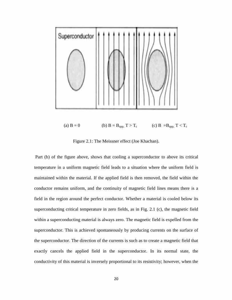
In general, the superconductors are classified into two types, Type I and Type II,
depending on various criteria. Type I superconductors have low critical field, the current
only flows through the surface, and these superconductors lose their superconductivity
very easily when placed in the external magnetic field compared to type II
superconductors, as shown in Figure 2.2 . This is largely due to the difference in
superconducting materials. For example, type I superconductors tend to be made of Tin,
or Aluminum, which are sometimes called “soft” superconductors, and the values of Hc
are always too low for type I superconductors to have application in coils for
superconducting magnets. Type II, on the other hand, tend to consist of materials such as
Niobium Titanium and Yttrium Barium Copper Oxide, which have much higher critical
fields and start to lose their superconductivity at a lower critical magnetic field, while
they completely lose their superconductivity at the upper critical magnetic field. Type II
superconductors are used for strong field superconducting magnets, as shown in Figure
2.2. Increasing the applied field from zero results in two critical fields, 𝐵c1and 𝐵c2; at
𝐵c1the applied field begins to partially penetrate the interior of the superconductor. The
superconductivity is maintained at this point, however. The superconductivity vanishes
above the second, much higher, critical field, 𝐵𝑐2. For applied field between 𝐵𝑐1and 𝐵𝑐2,
the applied field is able to partially penetrate the superconductor, so the Meissner effect is
incomplete, allowing the superconductor to tolerate very high magnetic fields. In the
region between 𝐵 and 𝐵 the superconductor is threaded by flux lines and is said to be
22
in the vortex state. Type II superconductors are the most technologically useful because
the second critical field can be quite high, enabling high field electromagnets to be made
out of superconducting wire. This makes them useful for applications requiring high
magnetic field, such as Magnetic Resonance Imaging (MRI) machines (Yi et al. 2005).
Figure 2.2: Type I and II superconductor behavior (Joe Khachan).
Since the discovery of superconductivity, there have been a number of efforts devoted to
establishing new applications for it, as well as explaining it theoretically. The discovery
of the Meissner effect led to the phenomenological theory of superconductivity of Fritz
and Heinz London in 1935. This theory explained resistance-less transport and the
Meissner effect, and allowed the first theoretical predictions to be made for
superconductivity. However, this theory only explained experimental observations. It did
not allow the microscopic origins of the superconducting properties to be identified. This
was done successfully by the Bardeen Cooper Schrieffer (BCS) theory in 1957, from
which the microscopic origins of the penetration depth and the Meissner effect are
explained.
23
Since then, several scientists have come forward with new theories and ideas, as the
power of superconductors has been observed and increasingly understood (kittel, 8th
ed.
2005).
2.3 Vortex lattice or Abrikosov lattice
Stable levitation of a permanent magnet above a small and flat superconductor only
occurs for type II superconductors. Certainly, levitation occurs when using type I
superconductors, but in a type II superconductor, the levitation is particularly stable and
robust. The answer lies in the properties of type II superconductors for an applied
magnetics field between two critical fields, Bc1 and Bc2. These normal regions allow the
penetration of the magnetic field in the form of thin filaments, usually called flux lines,
fluxoids or vortices. Such vortices lattices are named after their discoverer Abrikosov, the
Noble prize winning physicist. The super-currents circulate around the normal non-
superconducting core of each vortex; the core has a size ζ. Around the normal core, there
is a circulating super current. The direction of circulation is such that the direction of
magnetic field created by this current coin sides with the direction of external magnetic
field. The size of the region where the super current circulates λ, from the core of the
vortex lattice. The circulating super-currents induce magnetic flux that is equal to the
magnetic flux quantum. This Abrikosov vortex is also termed a fluxon. The average
vortex lattice density is proportional to the flux density of the applied magnetic field.
Once the theory of type II superconductors was developed, this led to the commercial
development of strong-field superconducting magnets. Consider the interface between a
24
region in the superconducting state and a region in the normal state. The interface has a
surface energy that may be positive or negative and that decreases as the applied
magnetic field is increased. A type I superconductor has positive free energy of the
superconductor-normal metal boundary, and the coherence length ζ (length over which
superconductivity changes) is bigger than the penetration depth λ. A superconductor is
type II if the surface energy becomes negative as the magnetic field is increased and the
coherence length is shorter than the penetration depth. Then it is energetically favourable
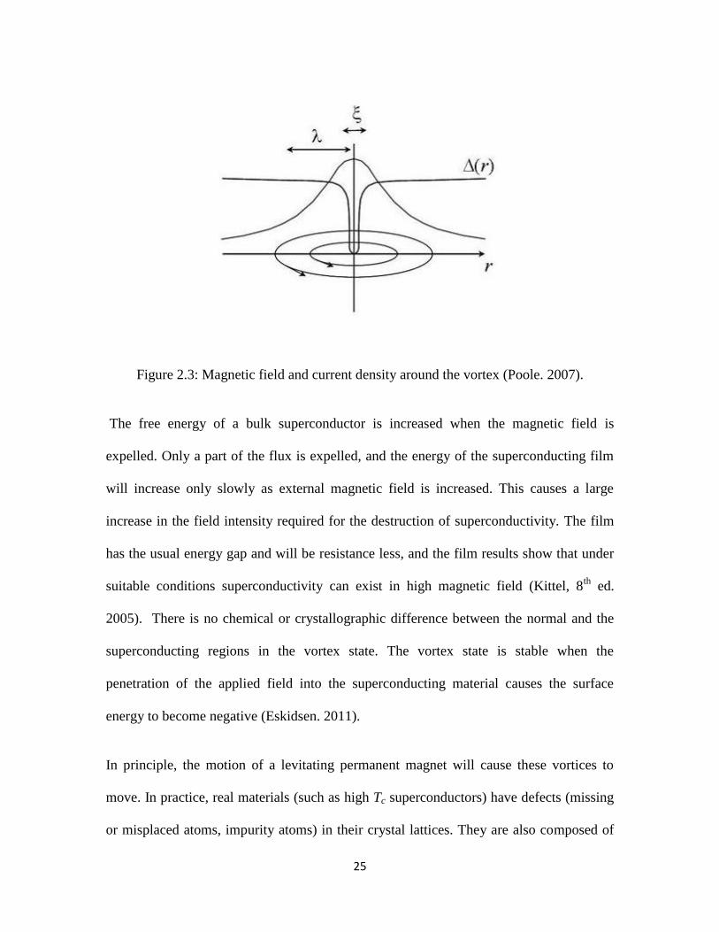
for vortices to form. Figure 2.3 show the magnetic field and current density around a
vortex. At the vortex there is one magnetic flux quantum (
) that
enters the superconductor. Around the vortex superconducting current are trying to keep
the field out. The magnetic field decreases exponentially from the center of the vortex. In
the center of the vortex the superconducting order parameter Δ goes to zero. This means
that in this region the metal is no longer a shorter than the penetration depth λ this defines
a type II superconductor and makes the formation of vortices favourable (Poole. 2007).
25
Figure 2.3: Magnetic field and current density around the vortex (Poole. 2007).
The free energy of a bulk superconductor is increased when the magnetic field is
expelled. Only a part of the flux is expelled, and the energy of the superconducting film
will increase only slowly as external magnetic field is increased. This causes a large
increase in the field intensity required for the destruction of superconductivity. The film
has the usual energy gap and will be resistance less, and the film results show that under
suitable conditions superconductivity can exist in high magnetic field (Kittel, 8th
ed.
2005). There is no chemical or crystallographic difference between the normal and the
superconducting regions in the vortex state. The vortex state is stable when the
penetration of the applied field into the superconducting material causes the surface
energy to become negative (Eskidsen. 2011).
In principle, the motion of a levitating permanent magnet will cause these vortices to
move. In practice, real materials (such as high Tc superconductors) have defects (missing
or misplaced atoms, impurity atoms) in their crystal lattices. They are also composed of
26
many crystals, all bound together, resulting in many crystal boundaries. The crystal
defects and boundaries stop the motion of the vortices, which is known as flux pinning.
This provides the stability of a levitating magnet. Pinning can only occur in type II
superconductors. This demonstration with high temperature superconductors indicates
that they are of type II.
The number of vortices representing the best compromise for a superconductor depends
on both the temperature and the applied magnetic field. However, vortices are not always
very mobile; their mobility depends on how the superconducting material was
manufactured. When the vortices can easily move in and out of the superconductor,
pinning is very weak. When the vortices are completely frozen in their position, though,
pinning is very strong. Multiple factors determine the pinning force of vortices: the
presence of impurities, flaws, the crystallographic quality of the material, the value of the
critical current.
2.4 Pinning properties
Flux pinning is the phenomenon in which the magnetic flux lines do not move and
become trapped (or pinned) in spite of the Lorentz force acting on them inside a current-
carrying Type II superconductor. In flux pinning, some of the magnetic field lines have
penetrated the sample and are trapped in defect and grain boundaries in the crystals. The
phenomenon cannot occur in type I superconductors, since these cannot be penetrated by
magnetic fields. Flux pinning is possible when there are defects in the crystalline
structure of the superconductor (usually resulting from grain boundaries or impurities, or
lattice distortions).
27
There are several methods for inducing flux pinning in superconducting materials – such
as the inclusion of nano-composite material in the superconductor; These inclusions act
as pinning centers, and their design and introduction are also termed as Artificial Pinning
Center technology (APC); The introduction of Cu-Sn nanometric pinning centers into the
Nb3Sn phase has been performed through successive binding and deformations, leading
to Cu (Sn) deformation centers as small as 40 nm. The results of critical currents
analyzed through these techniques are found to be much higher than for
stoichiometric Nb3Sn superconducting magnets (Rodrigues. 2007).
There have been further investigations of incorporation of components such as Nb in Nb-
Ti material to study the flux pinning behavior in the superconducting material, and a
greater increase in the pinning forces and critical current densities in these materials, was
demonstrated. The effect was further improved by heat treatment methods (Okuba. 2000).
There is evidence of improved flux pinning by nano-particle inclusions in thin film
superconductors, it was experimentally proved for high field applications that MgO
inclusions in MgB2 thin films contributed to improved core pinning (Sung et al. 2003).
Nano-metric Cu inclusions in Nb phase on the order of 43 nm contributed to greater
improvement in critical current density in Cu-Nb composite superconducting materials.
This was realized by increasing the pinning centre density in the composite
superconducting material.
Pancake vortices, one extreme case of type II superconductor vortices (approximated by
many cuprates), consist of a stack of two-dimensional superconducting layers. Coupling
28
in a pancake vortex is confined to one layer and is so called because its extent in that
layer is much larger than the layer spacing. Despite the lack of phase coherence, the
magnetic energy suffices to align the vortex positions in adjacent layers (at T = 0).
Otherwise, flux must travel horizontally between the layers connecting one vortex to the
next. When there are thermal or pinning fluctuations, however, and a high vortex density,
it may no longer be possible to say which vortex in one layer corresponds to which one in
the next layer (Buzdin et al. 2002).
Flux vortex is subject to a Lorentz force per unit length = , where is the
current density, is a unit vector along the flux line and is the flux quantum.
Averaging over a number of vortices gives the Lorentz force density.
(2.1)
This force tends to move flux lines in direction perpendicular to that of the current flow,
inducing an electric field normal to both the movement and the field direction. The value
of the electric field is given by:
(2.2)
Where is the velocity of the moving flux line.
A simple model of flux flow considers a viscous drag coefficient η, such that the viscous
force per unit length on a vortex moving with velocity is - η . Then a simple force
balance equation is:
(2.3)
29
and the flux flow resistivity, defined by = is given by
(2.4)
This flux flow resistivity is related approximately to the normal state resistivity , and
the upper critical field 𝐵 , by
(2.5)
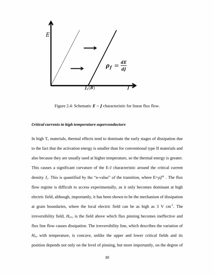
In order that dissipation by flux flow does not begin as soon as vortices enter a type II
superconductor, it is necessary that there is a force opposing the Lorentz force to the
vortices in place. Such vortex pinning sites provided by defects in superconductor which
act as energetically favourable sites at which a flux line can reside. The presence of such
favourable sites for pinning creates an average pinning force for flux line lattice,
which opposes the Lorentz force. Hence there is a finite critical current density, , as
shown in figure 2.4:
30
𝐸
𝝆 𝒅
𝒅
Figure 2.4: Schematic characteristic for linear flux flow.
Critical currents in high temperature superconductors
In high Tc materials, thermal effects tend to dominate the early stages of dissipation due
to the fact that the activation energy is smaller than for conventional type II materials and
also because they are usually used at higher temperature, so the thermal energy is greater.
This causes a significant curvature of the E-J characteristic around the critical current
density Jc. This is quantified by the “n-value” of the transition, where E= . The flux
flow regime is difficult to access experimentally, as it only becomes dominant at high
electric field, although, importantly, it has been shown to be the mechanism of dissipation
at grain boundaries, where the local electric field can be as high as 3 V cm-1
. The
irreversibility field, Hirr, is the field above which flux pinning becomes ineffective and
flux line flow causes dissipation. The irreversibility line, which describes the variation of
Hirr with temperature, is concave, unlike the upper and lower critical fields and its
position depends not only on the level of pinning, but more importantly, on the degree of
31
coupling between CuO2 planes, for example, in a cuprate superconductor. Hence, for
poorly coupled materials such as bismuth strontium calcium copper oxide (BSCCO), the
irreversibility line is much lower than for materials such as YBCO (Dew-Hughes, 2001).
2.5 Applications of superconductor (SCs) and future developments
Due to the continuous efforts made by the researchers towards expanding superconductor
usage, future developments are going to be numerous. Promising applications of
superconductors for the near future include:
Electric power transmission systems
Electric motors (possibly including application in ship and vehicles propulsion
systems such as are commonly found in maglev trains or in vactrains).
Transformers.
Smart grids.
Nanotechnology (in nanoscopic materials).
Superconducting magnetic refrigeration systems.
Recent research on the nature and potential of superconducting magnets has revealed that
the superconductors exhibit distinct properties that could be applied in several other
applications. There are greater prospects if superconductors are applied to industrial
processing, instrumentation, high-end computing, and cryogenics (CSC. 2009).
When future developments are evaluated based on their industry wide classification,
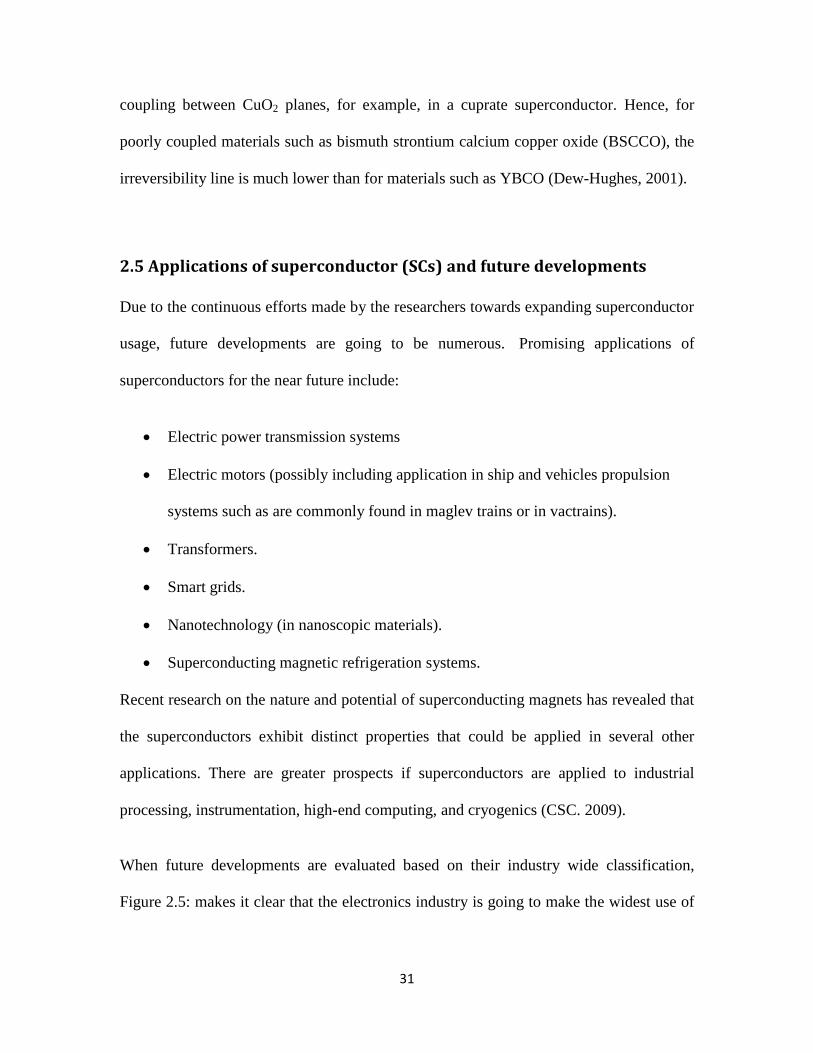
Figure 2.5: makes it clear that the electronics industry is going to make the widest use of
32
superconductors. In second place, it is the energy industry that is about to make wide use
of superconductors in its energy storage and maintenance systems.
Figure (2.5): Future developments of superconductors.
Retrieved from http://global-sei.com/super/about_e/application.html
The graph on the right of Fig. 2.5 shows that the world is bound to make huge use of
superconductors in the near future. The first in the order of highest usage would be USA,
followed by Japan and finally, Europe.
Future developments are not restricted to the ones mentioned above. Superconductors can
also be used in propulsion systems, and these applications now exist in several countries
around the world.
Superconductors can also be used to make a device known as a superconducting quantum
interference device (SQUID). This is incredibly sensitive to small magnetic fields so that
it can detect the magnetic fields from the heart (10-10
Tesla) and even the brain (10-13
Tesla). For comparison, the Earth’s magnetic field is about 10-4
Tesla. As a result,
33
SQUIDs are used in non-intrusive medical diagnostics on the brain (Yuichi Yamada et al,
2007).
On the other hand, applications are now used commonly in hybrid automobiles.
Advances are now taking place in the application of HTS wires. Magnetocardiography
(MCG) works with the help of sensitive SQUIDs. MCG produces unprecedented
accuracy.
The future of superconductors will lead to increased usage in the healthcare sector, in
addition to the transportation and automobile sector because superconductors are
expected to reduce the health care costs.
One use of large and powerful superconducting electromagnets is in a possible future
energy source known as nuclear fusion. When two light nuclei combine to form a heavier
nucleus, the process is called nuclear fusion. This results in the release of large amounts
of energy without any harmful waste. Two isotopes of hydrogen, deuterium and tritium,
will fuse to release energy and helium. Deuterium is available in ordinary water and
tritium can be made during the nuclear fusion reactions from another abundantly
available element, lithium. For this reason it is called clean nuclear energy. For this
reaction to occur, as a result, they must be heated to millions of degrees so that they
become fully ionized. As a result, they must be confined in space so that they do not
escape while being heated. Large and powerful electromagnets made from
superconductors are capable of confining these energetic ions. An international fusion
energy project, known as the International Thermonuclear Experimental Reactor (ITER)
is currently being built in the south of France that will use large superconducting magnets
34
and is due for completion in 2017. Large mass density is also important for nuclear
fusion, achieving of which requires strong magnetic fields. It is expected that this will
demonstrate energy production using nuclear fusion (Okuno et al. 2004).
35
Chapter 3 Superconducting Magnetic Energy Storage:
3.1 Introduction
Energy storage systems using superconducting magnets could store significantly more
energy than other technologies. The conductor for carrying the current operates at
cryogenic temperatures where it is a superconductor and thus has virtually no resistive
losses as it produces the magnetic field. The overall technology of cryogenics and
superconductivity today is such that the components of a SMES device are well
defined and can be constructed. Magnetic energy storage systems have been under
development for some time; however, past devices were designed to supply power only
for short durations generally less than a few minutes. SMES systems would deliver the
stored energy at very low cost that is competitive with other technologies SMES is the
only technology based on superconductivity that is applicable to electric utilities and
commercially available today.
3.2 Magnets
Magnets form the basis of the superconducting magnetic energy storage system (SMES).
These are superconducting magnets, but there are also magnets used for magnetic energy
storage that are not of the superconducting type (Boom and Peterson, 1972). In general,
magnets are classified depending on their strengths. Of late, this categorization has
enabled people to identify the right set of magnets that would be suitable for the
application. These magnets are widely used in energy storage and maintenance systems.
36
Superconducting magnets
Superconducting magnets have the ability to overcome electrical resistance so long as
they are kept cold enough. These magnets are generally used in magnetic resonance
imaging (MRI) machines. Researchers have found that superconducting magnets also
have a wide range of applications in levitating trains. Furthermore, they are also used in
superconducting magnetic energy storage systems where the magnet enables storage and
maintenance of the energy within the system.
There are three components that form a complete SMES system. These include:
Superconducting coil
Refrigerator that is set at cryogenically cooled temperature
Power conditioning system
Perhaps, it is the superconducting magnet that is fundamental to the system.
Superconducting coil
The coil is set at a cryogenically cooled temperature and is allowed to charge completely.
As soon as it has attained complete charge, the current flowing through the coil will never
decay, and thus, the storage of magnetic energy is feasible over a longer time. The main
purpose of the superconducting coil is to store the energy and to discharge it as and when
required. This implies that the superconducting coil allows the release of the stored
energy to the SMES network (Padimiti. 2007). A SMES coil can be constructed in many
different configurations. One of the most common types is the solenoid-type winding. For
37
a solenoid the stored energy per unit length of superconductor is roughly twice as high as
for a trous. Since the superconductor losses are proportional to the length of the
superconducting cable. A single solenoid model causes a lot of stray field effects, and
hence a large number of small size solenoids can be constructed, although they end up
using more conductor material (Kim et al. 2005). The toroidal type SMES coil reduces
stray field effects to a large extent, but the magnetic force is increased and more
superconducting material is required. Toroidal SMES systems suffer from considerably
higher superconductor losses. However if the solenoid is pool cooled, the benefit of fewer
superconductor losses decreases.
Power conditioning system (PCS)
The power conditioning system (PCS) comprises an inverter or rectifier which is meant
to support the conversion between alternating and direct currents. It can be either from
AC to DC or DC to AC. A PCS consists of a dc-dc chopper and a 3 phase voltage source
converter (VSC). Using the voltage- angle control strategy, both the active and reactive
power can be controlled. A dc-dc chopper is mainly used to keep the current through the
SMES coil constant and to transfer the power to the VSC through the dc-link capacitor.
The SMES coil along with a dc-dc chopper is connected to the VSC through a dc-link
capacitor. This capacitor acts as a temporary dc voltage source for the VSC to inject
active/reactive power into the grid. During the flow of energy, the inverter permits an
energy loss of about 2-3% in every direction. This is definitely a method meant for
energy storage; this system is found to be the most capable one because it loses only a
very small portion of the energy (Molina et al. 2011).
38
Refrigerator
The cryogenic system forms the most vital part of the SMES system. Superconducting
magnets have to be kept in the required temperature range to maintain their
superconducting nature and carry high current which create strong magnetic field. This
component is especially intended to moderate the temperature within the system. The
magnet operates at a cryogenically cooled temperature in order to store and discharge
energy with greater efficiency and minimum loss. This component ensures that the
temperature is set perfectly for the energy to flow accordingly (Ise et al. 1994).
Charging system
The operation of the superconducting magnet involves a power supply for operation on
persistent mode. The changes that are made on the current via the magnet must be done
in a slow manner because of the large voltage spike that might be caused between the
windings due to abrupt changes. The operation of the superconductor in persistent mode
enables stability within the magnetic field. Also, there will be control of the energy
consumption. Quench is a sudden end of operation, which generally takes place when a
section of the coil becomes resistive. This can occur because the field inside the magnet
is too large, the rate of change of field is too large, or a combination of the two. More
rarely, a defect in the magnet can cause a quench. When this happens, that particular spot
is subject to rapid joule heating, which raises the temperature of the surrounding regions.
When the operation becomes normal all of a sudden, this might be the result of such a
defect and requires replacement of the magnets that are being used at the moment (Rao.
2008).
39
In this research system, most of the volume is occupied by the refrigeration system,
which depends on cryogenic liquids and evacuated spaces, as in a thermos bottle. The
actual magnet coils are located in the lower part of the system, and the bore is used for
samples to be studied under the very high magnetic field produced by the magnet.
Scientists are currently working on superconducting magnets where the fields are set
even higher (up to 38 tesla).
Superconducting wires
The majority of superconducting magnets are wound with conductors (for instance,
niobium – titanium alloy in a copper matrix). Including these conductors in the
superconducting magnets stabilizes the charging and discharging process within the
energy system (Yuan et al. 2010). The other commonly used materials in real time
applications are:
Niobium – Tin conductor – These conductors are used together with niobium –
titanium single filaments. This type of conductor is generally expensive, tough to wind
and costlier than NbTi for magnets. SMES systems that use NbTi coils are cooled with
liquid helium (LHe). Using LHe is impediment from the cooling system point of view
because LHe itself is very expensive compared to liquid nitrogen (L ) and LHe requires
heavy installation. This feature of cryocoolers is important; the operating temperature
range of an NbTi coil will be between 10 K and 20 K to increase the critical current for
the coil (Venkataratnam et al.1999).
Yttrium-barium copper oxide or YBCO (thin film, coated conductor), is a
crystalline chemical compound. It is regarded as a high temperature superconductor and
40
is still identified as the first material that achieved superconductivity above 77 K, which
is the boiling point of liquid nitrogen. YBCO is highly applicable for energy storage
purposes. YBCO single crystals possess high critical current density. The poly-crystals,
however, exhibit a low value of critical current density. Generally, YBCO is deposited on
flexible metal tapes. The result of this process is termed “coated conductor”. The
multilayered structure of YBCO helps in the improvement of current-carrying capacity
(Pan et al. 2006). An YBCO SMES is smaller than an Nb-Ti SMES and can function
under higher temperature, owing to its high Ic/Jc -B properties. Because of their different
electrical properties, YBCO SMES and Nb-Ti SMES must have different types of
systems (Fujiwara et al. 2010).
Magnesium diboride (Mg𝐵 ) is a simple ionic binary compound that has
proven to be an inexpensive and useful superconducting material. The highest
superconducting transition temperature is 39 K, which means that MgB2 based systems
can be cooled by modern cryocooling device, without the costly problematic and
hazardous use of liquid helium. The most important difference between MgB2 and other
practical superconductors is that it has two superconducting gaps originating from two
different bands. Tuning the scattering rates between the two bands improves the
superconducting properties and the practical applicability of MgB2 (Vinod et al. 2006).
3.3 The modeling of an HTS pancake coil
Superconducting magnetic energy storage (SMES) systems possess greater cyclic
efficiency and quick response time. The development of such a system is based on
several parameters. The superconducting tape for the system has to be first chosen.
41
This could vary in terms of its thickness and diameter (Yuan et al. 2010). For an SMES
system, the inductively stored energy (E in Joules) and the rated power (P in Watts) are
the commonly given specifications for SMES devices, and can be expressed as follows:
Stored energy =
,
(3.1)
Where L is the inductance of the coil, I is the dc current flowing through the coil, and V is
the voltage across the coil.
The coil for maximum energy storage is not the same as the coil for maximum inductance
(L max) for superconductors. This is due to the fact that maximum inductance leads to
higher field (above the critical field) at lower coil-current (which cannot be increased
beyond the reduced critical current of the conductor) (Rao. 2008). This configuration of
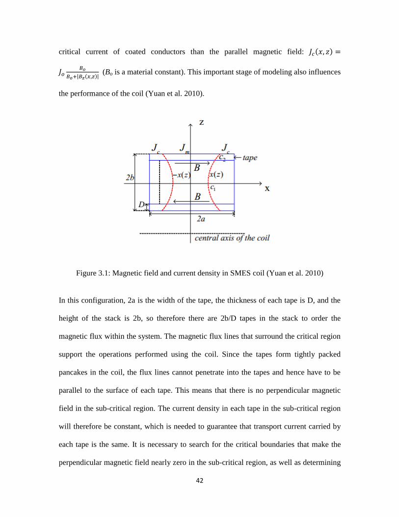
the stacked pancake coil is illustrated in Figure 3.1.
The most important step in the entire development process lies in the modelling.
Superconductors need to be handled very carefully, as they have distinct properties that
should never be affected by any sort of external factors, and they are also intrinsically
expensive (Choi et al. 2009). The modeling function starts with the basic assumption that
the distribution of current density covers the cross-sectional area of every tape.
To develop a superconducting magnetic energy storage system, it is important to classify
the coil into two different regions, namely the critical and the sub-critical regions, which
are presented in Figure 3.1, with the regions highlighted. The critical regions are
constrained by a curve rather than a straight line. The critical region Jc (x,z) depends on
the local Bz (x,z), as the perpendicular magnetic field has a much larger effect on the
42
critical current of coated conductors than the parallel magnetic field:
| | (Bo is a material constant). This important stage of modeling also influences
the performance of the coil (Yuan et al. 2010).
Figure 3.1: Magnetic field and current density in SMES coil (Yuan et al. 2010)
In this configuration, 2a is the width of the tape, the thickness of each tape is D, and the
height of the stack is 2b, so therefore there are 2b/D tapes in the stack to order the
magnetic flux within the system. The magnetic flux lines that surround the critical region
support the operations performed using the coil. Since the tapes form tightly packed
pancakes in the coil, the flux lines cannot penetrate into the tapes and hence have to be
parallel to the surface of each tape. This means that there is no perpendicular magnetic
field in the sub-critical region. The current density in each tape in the sub-critical region
will therefore be constant, which is needed to guarantee that transport current carried by
each tape is the same. It is necessary to search for the critical boundaries that make the
perpendicular magnetic field nearly zero in the sub-critical region, as well as determining
43
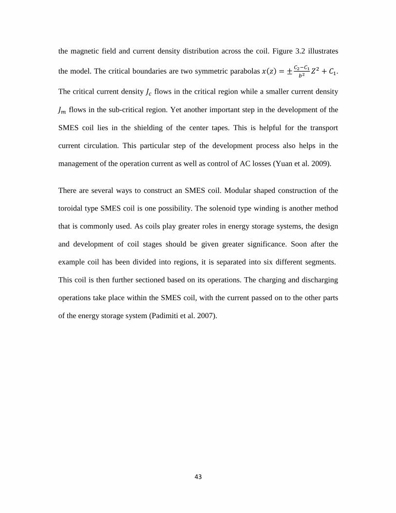
the magnetic field and current density distribution across the coil. Figure 3.2 illustrates
the model. The critical boundaries are two symmetric parabolas
.
The critical current density flows in the critical region while a smaller current density
flows in the sub-critical region. Yet another important step in the development of the
SMES coil lies in the shielding of the center tapes. This is helpful for the transport
current circulation. This particular step of the development process also helps in the
management of the operation current as well as control of AC losses (Yuan et al. 2009).
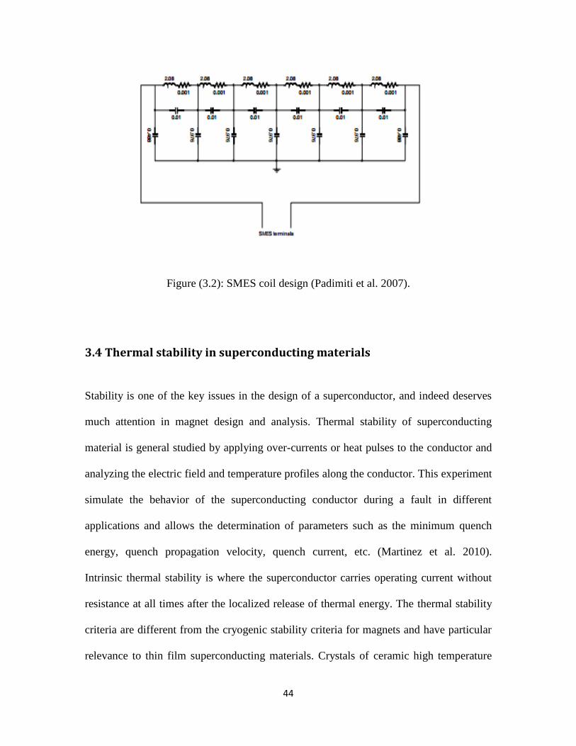
There are several ways to construct an SMES coil. Modular shaped construction of the
toroidal type SMES coil is one possibility. The solenoid type winding is another method
that is commonly used. As coils play greater roles in energy storage systems, the design
and development of coil stages should be given greater significance. Soon after the
example coil has been divided into regions, it is separated into six different segments.
This coil is then further sectioned based on its operations. The charging and discharging
operations take place within the SMES coil, with the current passed on to the other parts
of the energy storage system (Padimiti et al. 2007).
44
Figure (3.2): SMES coil design (Padimiti et al. 2007).
3.4 Thermal stability in superconducting materials
Stability is one of the key issues in the design of a superconductor, and indeed deserves
much attention in magnet design and analysis. Thermal stability of superconducting
material is general studied by applying over-currents or heat pulses to the conductor and
analyzing the electric field and temperature profiles along the conductor. This experiment
simulate the behavior of the superconducting conductor during a fault in different
applications and allows the determination of parameters such as the minimum quench
energy, quench propagation velocity, quench current, etc. (Martinez et al. 2010).
Intrinsic thermal stability is where the superconductor carries operating current without
resistance at all times after the localized release of thermal energy. The thermal stability
criteria are different from the cryogenic stability criteria for magnets and have particular
relevance to thin film superconducting materials. Crystals of ceramic high temperature
45
super-conductors are likely to exhibit anistropic thermal conductivity, which was found
to have a high influence on their thermal stability (Flik et al. 1990).
Several studies have been conducted on the thermal stability in multifilamentary
connected super-conducting materials – as long as the filling factor is constant, there was
no effect found on the thermal stability of the superconducting materials, irrespective of
the superconductor location in the strand. The filling factor is the ratio of the
superconductor volume to the coil volume.
YBCO coated conductors have been the subject of intense research activities in recent
years due to their promising properties for use in electric power applications, such as
cables, magnets, motors, generators, and superconducting fault current limiters (SFCL).
In most applications the nominal current is below the critical current , and therefore the
dissipation in the superconducting material is only generated by the AC losses. In
contrast, SFCLs, especially the resistive type, are based on the superconducting. To
normal transition induced by a current higher than Martinez et al. 2010).
To study the micro structure and superconducting properties of YBCO films irradiated by
nanosecond pulsed excimer lasers, superconducting YBCO thin films were deposited in
situ on (100) LaAl03 substrates using the pulsed laser evaporation technique. These films
are found to exhibit excellent thermal stability. Also, there is improvement in the Jc of the
films due to the low energy density irradiation; however, for energy densities above the
melt threshold, the Jc values decreased sharply (Bhattacharya et al. 1991).
46
Under cryocooled conditions, when the thermal stability of reinforced Nb3Sn composite
superconducting materials are analyzed, it is found that the thermal stability is a function
of the thermal conductivity of the reinforced materials and hence affects the thermal
stability of the composite superconducting material.
Sputtering of amorphous-based thin film superconductors that contained a certain volume
percentage of metalloids was found to lead to good thermal stability after annealing
(Kondo. 1992).
Other issues that are considered in the thermal stability and related performance design of
the superconductor are the transient temperature response of the conducting material in
the vicinity of a quench, quench propagation time and minimum energy relations during
the temperature disturbance, etc. All these studies are required in the effective design of
the thermal stability of the superconductor (Johnstone et al. 2005).
3.5 Applications of SMES
The economic use of superconducting magnetic energy storage (SMES) will be most
likely attained by applying it simultaneously over a wide spread field of different tasks.
The first application is for a thermonuclear reactor. The second application is for large
particle accelerators, and the third application is for utility network conditioning. Despite
these potential applications, SMES imposes certain restrictions on the structure and
operation. One of the operating procedures for SMES states the need to maintain the
permanent current that is being circulated within the closed circuit. In this case, resistance
47
has to be low, and the closed circuit has to be developed from superconducting materials
(Masuda and Shintomi. 1977).
A superconducting magnetic energy storage (SMES) unit is a device for efficiently
storing energy in a magnetic field. it offers very fast exchange of power between the AC
power system and the superconducting coil. The potential applications of SMES in power
systems have been studied since the early 1970s. The 30 MJ SMES unit installed in the
Bonneville Power Administration (BPA) at1983 proved that an SMES has the capability
to improve damping of generators and augment dynamic stability. SMES permits fast
independent regulation of active and reactive power in four quadrants (Zheng Li et al.
2000).
The wide range of benefits that the superconducting magnetic energy storage systems
offer makes them widely applicable in various industries. Currently, SMES devices are
used in energy storage and power system applications. Modern power systems are very
dependent on stabilizing devices in order to ensure reliability as well as stability in their
operations. These also provide sufficient damping in the system (Xue et al. 2005). The
damping takes place during the transient period when line switching, fault clearance, and
load changes take place. Power system stability limitations are often characterized by low
frequency oscillations (0.5 Hz) following a major system disturbance. Power transfers are
often limited to prevent growing oscillations from occurring, following the loss of a
single major transmission line or generator. When the long-term stability is limited, the
transmission capacity can by increased by providing active damping of these oscillations.
SMES can actively damp these system oscillations through modulation of both real and
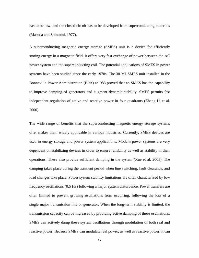
reactive power. Because SMES can modulate real power, as well as reactive power, it can
48
be much more effective and smaller in size, than other technologies. This damping is
represented in the following figure.
Figure 3.3: SMES unit applicable for damping system oscillations (Xue et al. 2005).
Superconducting coils which are cooled to a temperature below the superconducting
critical temperature are used to store energy – in systems which are often termed as
SMES – will take in direct current – which will be later stored in these coils in the form
of magnetic energy, and the energy contained in these coils can be later retrieved by the
use of rectifiers for several energy applications; They promise high quality power supply
with several advantages over conventional systems and find are finding application in
many domains requiring a varying range of capacities.
The next application is the usage of SMES systems in applications/systems requiring
voltage stability. These SMES systems ensure better efficiency in applications that
require their power outputs to be improved. The ability of the SMES systems to
compensate for fluctuating loads and enhance flexible AC transmission system (FACTS)
49
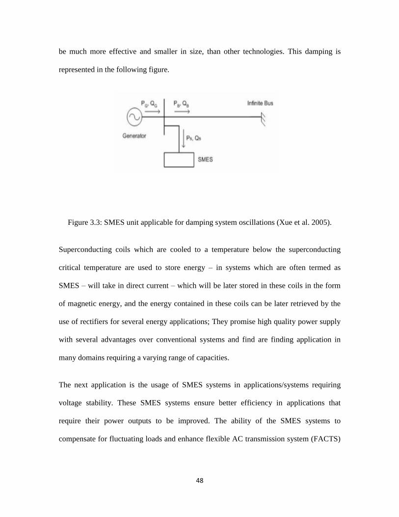
performance has extended domains of application (Xue et al. 2005). In the case of power
systems, the SMES applications are listed below:
Figure 3.4: Types of SMES applications for power systems (Xue et al. 2005).
SMES systems have wide applicability in the field of electrical power supply device. The
mechanical properties and AC loss characteristics that characterize second generation
HTS wires help in the enhancement of performance.
Such SMES applications are listed below:
Turbine systems.
Applications demanding control of AC losses.
Optimization of energy based storage system.
50
Electrical power applications.
Power transmission systems.
Load leveling applications.
The Distributed Superconducting Magnetic Energy Storage (D-SMES) System is an
innovative new application of proven SMES technology that provides two critical
capabilities. One is real energy storage through the use of superconductors, and the other
is instantaneous response through the use of power electronics. Superconductivity makes
it possible, by eliminating resistive losses within the magnetic coil, to store and
instantaneously discharge large quantities of power. The power electronics module,
which consists of an insulated-gate bipolar transistor (IGBT)-based voltage source
inverter system, uses advanced power electronics to detect voltage sags and to inject
precise quantities of real and reactive power to boost voltage on the transmission system
within a fraction of a cycle. D-SMES devices are most effective in addressing voltage
stability problems. They can be used for other applications, however, such as flicker
correction, capacitor bank switching, and other power quality solutions for both utility
and industrial applications. Some of the benefits of using the D-SMES device are: faster
voltage recovery when compared to other similar devices, distributed sources, low cost
when compared to traditional solutions, quick and easy installation with short lead times,
modular design to meet future load growth, and portability in case it has to be moved to
other locations (Kolluri. 2002).
Another application of zero–resistance or highly efficient energy conversion systems
containing high temperature superconducting units is in creating magnetic energy for
51
magnetic levitation for usage in high speed trains – which has been found to be highly
successful.
3.6 Ongoing SMES development
There are measures that are already being taken to restrain the costs to affordable values.
Plans that might improve the market for SMES systems include:
Cost reduction by the use of high temperature superconducting coils.
The commercialization of high-Tc superconducting (HTc) tapes has excited worldwide
research interest in power applications, because the use of superconductors can increase
the efficiency, and reduce the volume and weight of the power equipment because its
performance offers high current-density and low power loss. This is especially true for
superconducting power devices, such as HTS cable and high Tc superconducting
magnetic energy storage. It is expected that superconducting technologies will play an
important role in the future smart grid, because the application of superconductor
technologies in the power grid can decrease power losses, relieve overload, avoid higher
levels of transmission voltage, increase power transmission capacity and improve power
quality and grid stability (Zhang et al. 2011).
Reduction of costs for the conductor material and also for the refrigeration system
might directly reduce energy storage costs in SMES.
A low temperature SMES requires liquid helium for its operation, which makes it
expensive to operate, particularly because of the cryogenic system. With the availability
52
of a high temperature superconducting coil, only liquid nitrogen is required, which is
readily available and much cheaper than liquid helium. With higher temperatures come
not only reduced refrigeration costs but also enhanced reliability (Sutanto et al. 2009).
Reduction of the cost of the power conditioning unit is likely in the future.
Prices can be reduced generally if research continues.
Currently, there is considerable research going on in improving the feasibility of high
temperature (Tc) superconductors in normal and high field applications (stronger
magnetic field applications). Also, in recent times, a great amount of work on very high
field superconductors has been carried out in many projects worldwide. These systems
are highly reliable and very efficient, and hence, are particularly popular for specific
applications requiring high quality power and also for the general energy applications.
High quality power applications such as chip manufacturing systems are dependent on
SMES as well as general applications such as (solar and, wind energy) are dependent on
SMES to deal with the intermittency problem. Also, SMES system is finding applications
in pulsed back-up utilities (short time back-up). A superconducting coil exhibits-zero
resistance for dc current
Future SMES systems will involve cost effective technology.
There are several R&D plans that are intended to widen the potential of superconductors
and superconducting magnetic energy storage systems (Rupich et al. 2010). Ongoing
SMES development demands the following:
Reducing the stress related issues.
53
Increasing the thickness of wires.
Control of the thickness.
Improved dynamic performance.
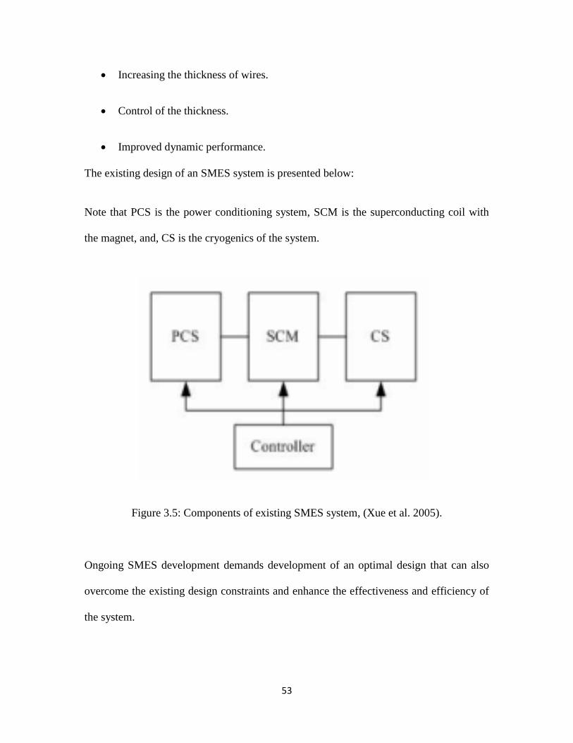
The existing design of an SMES system is presented below:
Note that PCS is the power conditioning system, SCM is the superconducting coil with
the magnet, and, CS is the cryogenics of the system.
Figure 3.5: Components of existing SMES system, (Xue et al. 2005).
Ongoing SMES development demands development of an optimal design that can also
overcome the existing design constraints and enhance the effectiveness and efficiency of
the system.
54
SMES also, has the ability to manage the spinning reserve and establish tie-line control
among the utility control areas. The power quality improvement feature of SMES has
made it viable for various lighting applications. In addition to these benefits, there are
certain secondary benefits offered by the superconducting coils (Ali. 2010). These might
include backup power supply, deferral of new capacity for transmission, extension of
available generating units, adherence to environmental regulations, and better
applications and lower use of energy resources.
3.7 Comparison of SMES and batteries
At the present stage, there are several applications making use of energy storage systems.
These energy storage systems are particularly meant to store the energy for a specific
period of time and discharge energy as and when required. In this process, there are
several constraints involved, such as design constraints, operation constraints and budget
constraints. Superconducting magnetic energy storage (SMES) systems are widely used
in various large-scale and power applications. On the other hand, batteries serve as a
great source for energy storage and generation. The working techniques in these systems
differ to a greater extent.
This section presents a broader overview on the working of batteries. Furthermore, the
energy storage systems that are commonly used for various applications are discussed,
out of which, SMES and batteries are chosen for comparisons. The comparisons are made
on various aspects in order to gain insight into the implications and applications of these
systems along with the nature of their potential. The research on the energy storage
55
systems has indicated that these systems could be applied in applications used in day–to–
day life.
Energy storage refers to the process of storing energy in order to enable the device to
carry out useful operations in the future. These systems are often denoted as
accumulators, due to their basic function. The energy being stored is either potential or
kinetic in nature (Connolly. 2010). Recently, there has been a demand for storing energy
from the non-renewable sources (exhaustible sources) of energy. Hence, system
development for the purpose of energy storage is continuing and is expected to be applied
over a wide range of domains.
The battery is used as an electrochemical storage system, although it has limited capacity.
The new technologies that have been developed for the battery, however, have improved
its load leveling capacity and energy storage functionalities. In certain cases, such as the
alternating current (AC) systems, electrical energy cannot be stored electrically. Yet, it
has to be generated as and when there is a demand in the market. For this case, energy
storage systems are required, and the energy is stored electromagnetically or kinetically,
or electrochemically.
The energy conversion technique in every energy storage technology is based on the
requirement or purpose. The energy conversion unit is meant to convert the energy to a
different form and back again. In other words, it is a process of charging and discharging
the energy from the storage system. The potential application of these systems include
dynamic voltage stability, load leveling, sub–synchronous resonance damping, spinning
reserve for the short term, and power quality improvement (Connolly. 2010).
56
Both, the Battery Energy Storage (BES) system and the Superconducting Magnetic
Energy Storage (SMES) system have multiple similarities as well as differences. Their
applications in the utility field are enormous, and their potential growth has been quite
evident. The operation of a BES system is quite similar to any other energy storage
system. There are a few constraints in terms of cost and maturity levels. For instance, the
lead acid battery can be used only for specific applications. The environmental tolerance
for some of the batteries is a major constraint. This does not happen in the case of the
SMES system, however.
The similarity between these systems lies in the basic characteristics that they are
dependent on. These include round trip efficiency, charging rate, discharging rate, energy
density, and performance. The following table 3.1 lists the differences in terms of the
suitability of these systems for utility applications (Akhil et al. 1993). The comparison is
made for both the current technologies and advanced technologies. In the case of SMES,
the systems in the current technologies employ low temperature superconductors, while
the advanced technologies are employing high temperature superconductors. These
classifications are not present in the case of BES. The batteries differ in terms of their
material, but are not based on any critical factors such as temperature. This is one major
difference between these two types of energy storage systems.
The BES could meet the basic performance requirements for the majority of applications.
Utilities generally are too concerned about reliability, energy density, and life span. In
case of SMES systems, they were able to meet the performance requirements only in
those systems with charging and discharging. The majority of the SMES systems
57
operating with high temperature superconductors led to the demand for more
development.
The basic requirement for a storage system to become a utility is quite simple. The
similarity is that the requirement is the same for both types of systems (Therond et al.
1993). There is a need for an interface to be established between the grid and the storage
device. This interface is meant to act as a power conversion subsystem. The advantage of
BES over SMES lies in the storage capacity of the former. The storage capacity is
enormous and flexible in case of BES. Therefore, this could be applied easily for large-
scale applications too.
Here is a broad classification between the two types of systems in terms of their
advantages and disadvantages. These differences have differentiated their application and
developments (Therond et al. 1993).
Superconducting magnetic energy storage (SMES) has a faster response and is more
economical, and environment-friendly than an uninterruptible power supply (UPS) using
batteries. Also, the SMES not only has the ability to control active and reactive power
simultaneously, but also has a long life-time because the superconducting magnet does
not have a degradation problem like the battery. Therefore, the SMES is a superior
candidate to the UPS using the battery. The SMES needs a cryogenic system without
exception. A conduction cooling system that has a simple, light and small structure is
well adapted to high temperature superconducting (HTS) SMES (Yeom et al. 2007).
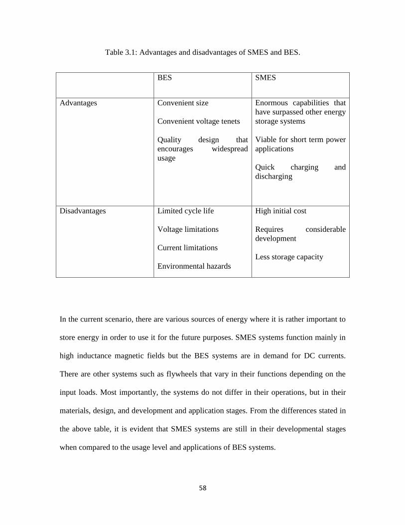
58
Table 3.1: Advantages and disadvantages of SMES and BES.
BES SMES
Advantages Convenient size
Convenient voltage tenets
Quality design that
encourages widespread
usage
Enormous capabilities that
have surpassed other energy
storage systems
Viable for short term power
applications
Quick charging and
discharging
Disadvantages Limited cycle life
Voltage limitations
Current limitations
Environmental hazards
High initial cost
Requires considerable
development
Less storage capacity
In the current scenario, there are various sources of energy where it is rather important to
store energy in order to use it for the future purposes. SMES systems function mainly in
high inductance magnetic fields but the BES systems are in demand for DC currents.
There are other systems such as flywheels that vary in their functions depending on the
input loads. Most importantly, the systems do not differ in their operations, but in their
materials, design, and development and application stages. From the differences stated in
the above table, it is evident that SMES systems are still in their developmental stages
when compared to the usage level and applications of BES systems.
59
Throughout, this chapter, the evaluations have been presented for each system in terms of
its present stage, as well as future developments. These are meant to assess the areas
where both systems fall short. The advantages and disadvantages are also classified. For
the SMES systems to become practical, it is important to overcome the technical
challenges. Likewise, BES systems need to improve their maturity level in order to
improve its practicality. With these broad differences and similarities, this chapter has
analyzed and given an overview of the two major energy storage systems that are now
used in every part of the world, ranging from short-term to long-term applications. This
chapter will also be helpful in identifying the potential areas that can be improved to
provide greater benefits in the near future.
3.8 Summary
The main purpose of using SMES devices is to store electrical energy in the magnetic
field of a large coil so that it can be used whenever it is needed. They are mainly used to
supply large, repetitive power pulses, and for load leveling applications. They can also be
used in power systems in order to increase the power quality. In this study, an attempt his
been made to make this coil small by using an HTS coil, which can store a large amount
of energy in a small coil because the amount of energy stored depends on the critical
current flowing through the coil, and the parameter of the thin film such as thickness and
width of the tape.
60
Chapter 4 Optimum Design of Superconducting Solenoid Coil for a SMES
Unit:
4.1 Introduction
In the previous chapter, the superconducting magnetic energy storage system was
explained. In this chapter, the design optimization for a superconducting solenoid coil
made of HTS tape for the purpose of energy storage is described. In this study, the
relationship between the geometrical parameters and the magnetic field are considered, as
well as various practical issues regarding the choice of a design for a prototype.
The design optimization for a superconducting solenoid coil in this study will use second
generation high-temperature superconducting wire (2G HTS), namely 𝑌𝐵𝑎2 𝑢3𝑂7−𝛿
(YBCO) coated conductor. The most significant benefit from the use of 2G HTS wire in
real-world applications is energy savings from improved efficiency (Xie et al. 2009).
There are three separate elements that have to be considered when designing a HTS
SMES coil the properties of the wire, the total length of the wire, and the stray fields. The
second and third elements are somewhat interrelated and are considered in the
optimization process at the same time. Depending on the shape and manufacturing
process, HTS wire acquires severely anisotropic characteristics according to the direction
of the external magnetic field.
The configuration of the coil needs to be considered in terms of its place of installation.
There are three types of coils that may be considered. The solenoid coil is easy to build,
but the stray field is too high to be viable in a densely populated area. Multiple solenoid
61
coils can be easily built with an even number of solenoid coils, but they require
significantly more conductor than simple solenoids. The toroid coil is ideal from the stray
field point of view, but it is hard to wind with tape-shaped HTS wires.
The design of a magnet coil also depends on the purpose for which it is going to be used.
For example, a highly uniform field is required for maximum stored energy and
minimum cost. The design in this research of the HTS SMES solenoid coil is aimed at
maximizing the stored energy (Chen et al. 2006). The energy (𝐸) stored in the magnetic
field of an inductor is proportional to its inductance ( ) and to the square of the current
flowing through its windings ( ). To calculate this energy we use Equation (3.1) (section
3.3).
It is obvious that if large currents flow through the windings of an inductor, a significant
amount of energy can be stored in its magnetic field. In the case of a superconducting
conductor, to store more energy, it is necessary to cause a larger current density to flow in
the coated conductor. The critical current density (Jc) is however, dependent on the
magnitude and orientation of the external magnetic field applied to the surface of the
coated conductor. Therefore, a design which yields the maximum value of is also the
design for maximum stored energy. An optimal solenoid has to be designed to have the
maximum inductance for a given length of conductor at its operating current. Since the
inductance of a solenoid is determined by the number of turns and the overall dimensions
of the winding, designing an optimal solenoid requires finding the number of turns and
the overall dimensions to achieve the maximum inductance for a given length of
conductor (So Noguchi et al. 2010).
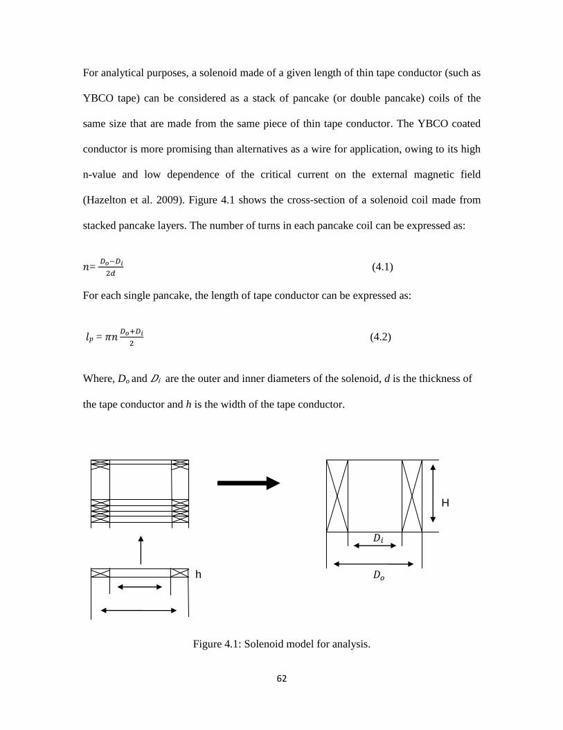
62
For analytical purposes, a solenoid made of a given length of thin tape conductor (such as
YBCO tape) can be considered as a stack of pancake (or double pancake) coils of the
same size that are made from the same piece of thin tape conductor. The YBCO coated
conductor is more promising than alternatives as a wire for application, owing to its high
n-value and low dependence of the critical current on the external magnetic field
(Hazelton et al. 2009). Figure 4.1 shows the cross-section of a solenoid coil made from
stacked pancake layers. The number of turns in each pancake coil can be expressed as:
=
(4.1)
For each single pancake, the length of tape conductor can be expressed as:
𝑙𝑝 =
(4.2)
Where, Do and 𝐷i are the outer and inner diameters of the solenoid, d is the thickness of
the tape conductor and h is the width of the tape conductor.
H
𝐷
h 𝐷
Figure 4.1: Solenoid model for analysis.
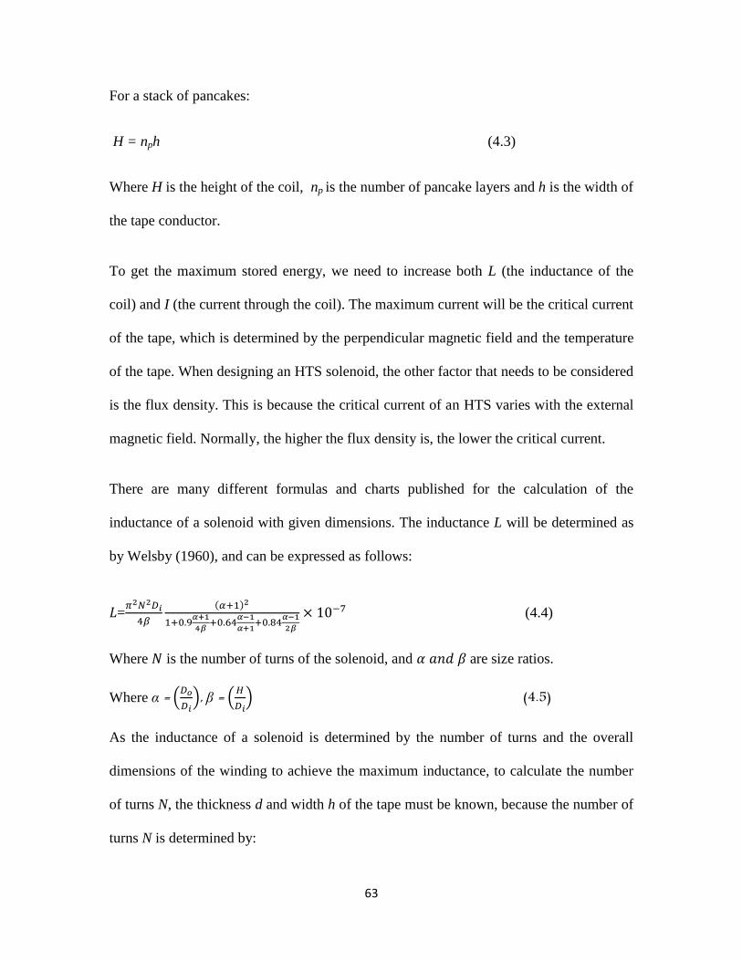
63
For a stack of pancakes:
H = nph (4.3)
Where H is the height of the coil, np is the number of pancake layers and h is the width of
the tape conductor.
To get the maximum stored energy, we need to increase both L (the inductance of the
coil) and I (the current through the coil). The maximum current will be the critical current
of the tape, which is determined by the perpendicular magnetic field and the temperature
of the tape. When designing an HTS solenoid, the other factor that needs to be considered
is the flux density. This is because the critical current of an HTS varies with the external
magnetic field. Normally, the higher the flux density is, the lower the critical current.
There are many different formulas and charts published for the calculation of the
inductance of a solenoid with given dimensions. The inductance L will be determined as
by Welsby (1960), and can be expressed as follows:
=
(4.4)
Where is the number of turns of the solenoid, and 𝑎 are size ratios.
Where α = (
), β = (
) (4.5)
As the inductance of a solenoid is determined by the number of turns and the overall
dimensions of the winding to achieve the maximum inductance, to calculate the number
of turns N, the thickness d and width h of the tape must be known, because the number of
turns N is determined by:
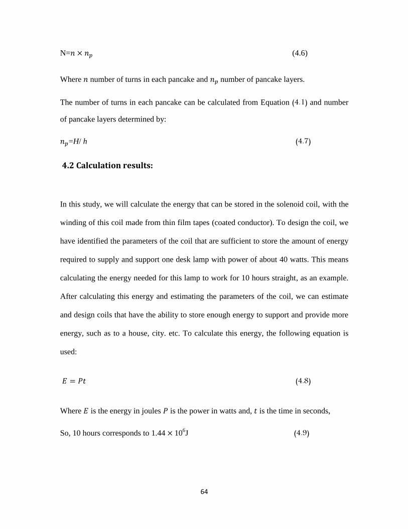
64
N= (4.6)
Where number of turns in each pancake and number of pancake layers.
The number of turns in each pancake can be calculated from Equation (4.1) and number
of pancake layers determined by:
=H/ h (4.7)
4.2 Calculation results:
In this study, we will calculate the energy that can be stored in the solenoid coil, with the
winding of this coil made from thin film tapes (coated conductor). To design the coil, we
have identified the parameters of the coil that are sufficient to store the amount of energy
required to supply and support one desk lamp with power of about 40 watts. This means
calculating the energy needed for this lamp to work for 10 hours straight, as an example.
After calculating this energy and estimating the parameters of the coil, we can estimate
and design coils that have the ability to store enough energy to support and provide more
energy, such as to a house, city. etc. To calculate this energy, the following equation is
used:
𝐸 (4.8)
Where 𝐸 is the energy in joules is the power in watts and, is the time in seconds,
So, 10 hours corresponds to 1.44 106J (4.9)
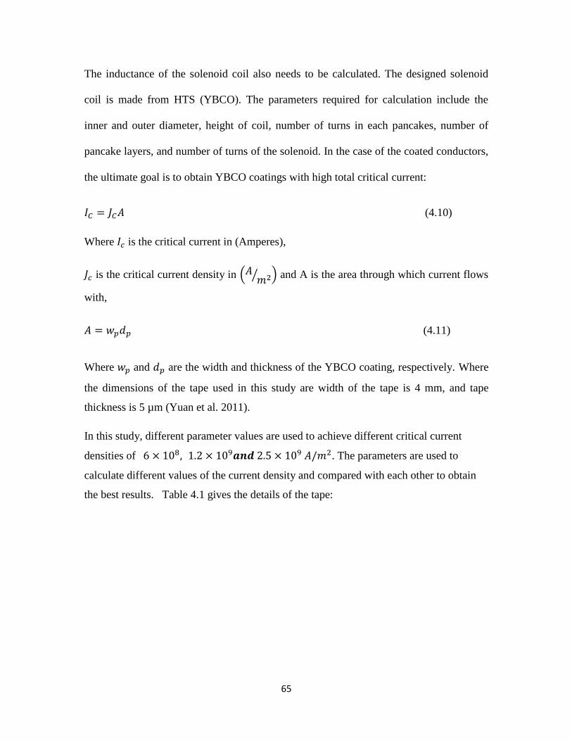
65
The inductance of the solenoid coil also needs to be calculated. The designed solenoid
coil is made from HTS (YBCO). The parameters required for calculation include the
inner and outer diameter, height of coil, number of turns in each pancakes, number of
pancake layers, and number of turns of the solenoid. In the case of the coated conductors,
the ultimate goal is to obtain YBCO coatings with high total critical current:
(4.10)
Where is the critical current in (Amperes),
is the critical current density in ( ⁄ ) and A is the area through which current flows
with,
(4.11)
Where and are the width and thickness of the YBCO coating, respectively. Where
the dimensions of the tape used in this study are width of the tape is 4 mm, and tape
thickness is 5 µm (Yuan et al. 2011).
In this study, different parameter values are used to achieve different critical current
densities of 𝒅 . The parameters are used to
calculate different values of the current density and compared with each other to obtain
the best results. Table 4.1 gives the details of the tape:
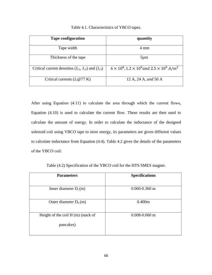
66
Table 4.1. Characteristics of YBCO tapes.
Tape configuration quantity
Tape width 4 mm
Thickness of the tape 5µm
Critical current densities (Jc1, Jc2) and (Jc3) 𝑎
Critical currents (Jc@77 K) 12 A, 24 A, and 50 A
After using Equation (4.11) to calculate the area through which the current flows,
Equation (4.10) is used to calculate the current flow. These results are then used to
calculate the amount of energy. In order to calculate the inductance of the designed
solenoid coil using YBCO tape to store energy, its parameters are given different values
to calculate inductance from Equation (4.4). Table 4.2 gives the details of the parameters
of the YBCO coil:
Table (4.2) Specification of the YBCO coil for the HTS SMES magnet.
Parameters Specifications
Inner diameter Di (m) 0.060-0.360 m
Outer diameter Do (m) 0.400m
Height of the coil H (m) (stack of
pancakes)
0.008-0.060 m
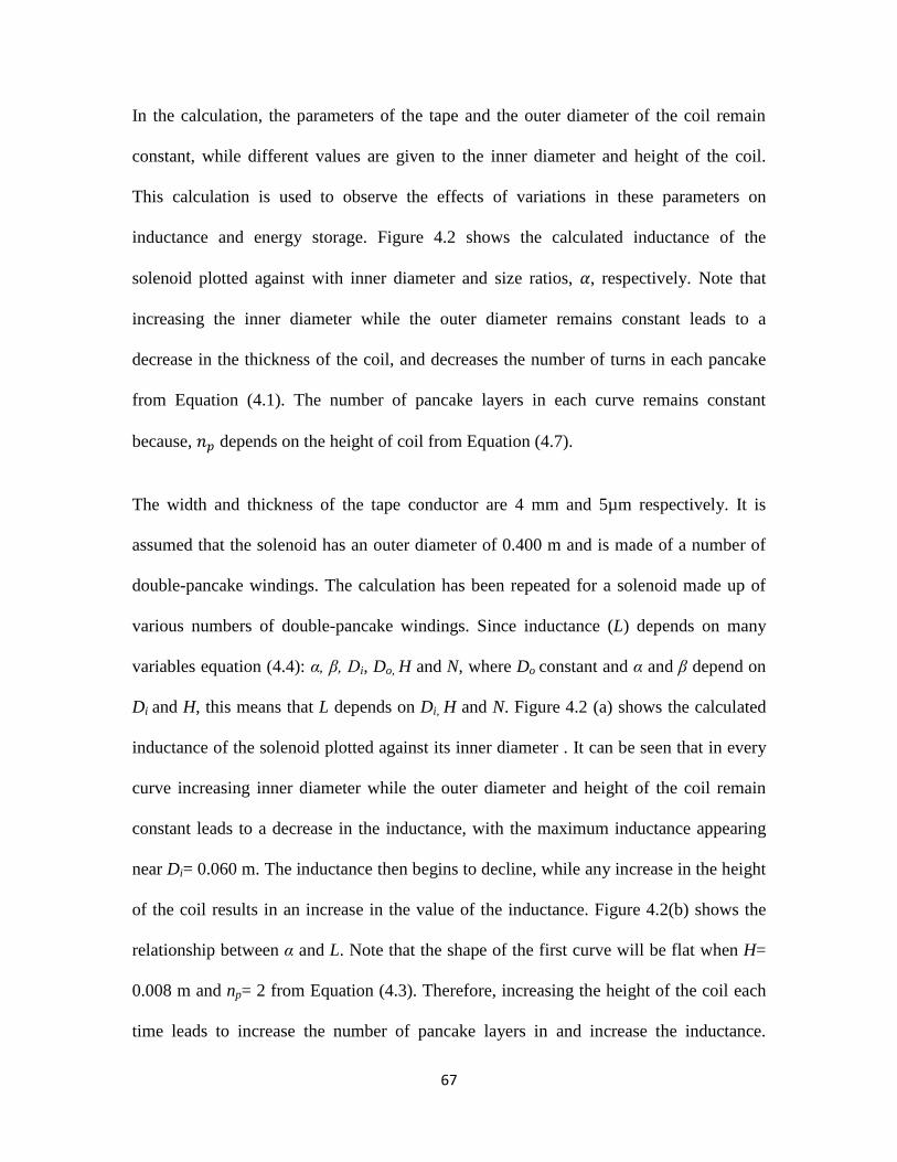
67
In the calculation, the parameters of the tape and the outer diameter of the coil remain
constant, while different values are given to the inner diameter and height of the coil.
This calculation is used to observe the effects of variations in these parameters on
inductance and energy storage. Figure 4.2 shows the calculated inductance of the
solenoid plotted against with inner diameter and size ratios, , respectively. Note that
increasing the inner diameter while the outer diameter remains constant leads to a
decrease in the thickness of the coil, and decreases the number of turns in each pancake
from Equation (4.1). The number of pancake layers in each curve remains constant
because, depends on the height of coil from Equation (4.7).
The width and thickness of the tape conductor are 4 mm and 5µm respectively. It is
assumed that the solenoid has an outer diameter of 0.400 m and is made of a number of
double-pancake windings. The calculation has been repeated for a solenoid made up of
various numbers of double-pancake windings. Since inductance (L) depends on many
variables equation (4.4): α, β, Di, Do, H and N, where Do constant and α and β depend on
Di and H, this means that L depends on Di, H and N. Figure 4.2 (a) shows the calculated
inductance of the solenoid plotted against its inner diameter . It can be seen that in every
curve increasing inner diameter while the outer diameter and height of the coil remain
constant leads to a decrease in the inductance, with the maximum inductance appearing
near Di= 0.060 m. The inductance then begins to decline, while any increase in the height
of the coil results in an increase in the value of the inductance. Figure 4.2(b) shows the
relationship between α and L. Note that the shape of the first curve will be flat when H=
0.008 m and np= 2 from Equation (4.3). Therefore, increasing the height of the coil each
time leads to increase the number of pancake layers in and increase the inductance.
68
Where there is a large increase in the value of the inductance, as in comparison between
the first and the last curve, this is because any increase in the number of pancake layers
means an increase in the number of turns in each pancake coil, height of the coil, and
length of the tape.
Equation (4.5) is used to calculate both α and β by setting different values to the inner
diameter and height of the coil, where α and β inversely proportional to Di. Therefore
when designing a coil for the purpose of obtaining a high value to inductance, we want to
know effect of each variable on inductance.
In this case, the solenoid with the maximum inductance has the following specifications:
inner diameter (given) = 0.060 m; outer diameter = 0.400 m, height = 0.060 m, number of
pancake layers = 15, number of turns in each pancake coil = 34000, number of turns of
the solenoid= 510000, and inductance = 40534.2henry. On a practical level, the coil can
be a single solenoid wound layer by layer, or a stack of pancake windings connected in
series.
69
(a): relationship between inductance and inner diameter.
(b): relationship between inductance and size ratio .
Figure 4.2: Calculated inductance of HTS solenoid versus inner diameter (a), and size ratios, (b), from Eq. (4.4)
70
4.3 Field-dependent current performance
There are several parameters that need to be considered when deciding the features of the
optimal design. The main parameter is the current bearing capability, since it is essential to
raise this capability as much as possible. This is generally implemented through the
binding conditions, because the current bearing capability of a second generation
superconducting solenoid coil is directly dependent on the distribution and direction of the
magnetic field, the calculation of its induction should involve both magnetic and
geometrical parameters (Feng, 1988).
The optimization of the design of a second generation superconducting solenoid coil has
been attempted using two different methods, an analytical method and a mathematical
model. The latter tends to be more cost efficient. This can help in achieving the expected
level of optimization.
Like its low-temperature counterpart, an HTS needs cooling. At a particular temperature
(77 K in liquid nitrogen), the critical current of an HTS varies with the external magnetic
field. Normally, the higher the flux density is, the lower the critical current becomes. An
HTS solenoid should be designed to ensure that the maximum flux density at the winding
is within the critical flux density of HTS performance at the operation temperature.
Otherwise, the solenoid will not be superconducting.
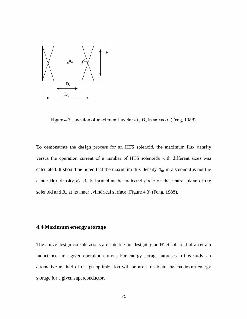
71
H
Di
Di
Do
Figure 4.3: Location of maximum flux density Bm in solenoid (Feng, 1988).
To demonstrate the design process for an HTS solenoid, the maximum flux density
versus the operation current of a number of HTS solenoids with different sizes was
calculated. It should be noted that the maximum flux density 𝐵 in a solenoid is not the
center flux density 𝐵 . 𝐵 is located at the indicated circle on the central plane of the
solenoid and Bm at its inner cylindrical surface (Figure 4.3) (Feng, 1988).
4.4 Maximum energy storage
The above design considerations are suitable for designing an HTS solenoid of a certain
inductance for a given operation current. For energy storage purposes in this study, an
alternative method of design optimization will be used to obtain the maximum energy
storage for a given superconductor.
𝐵 𝐵
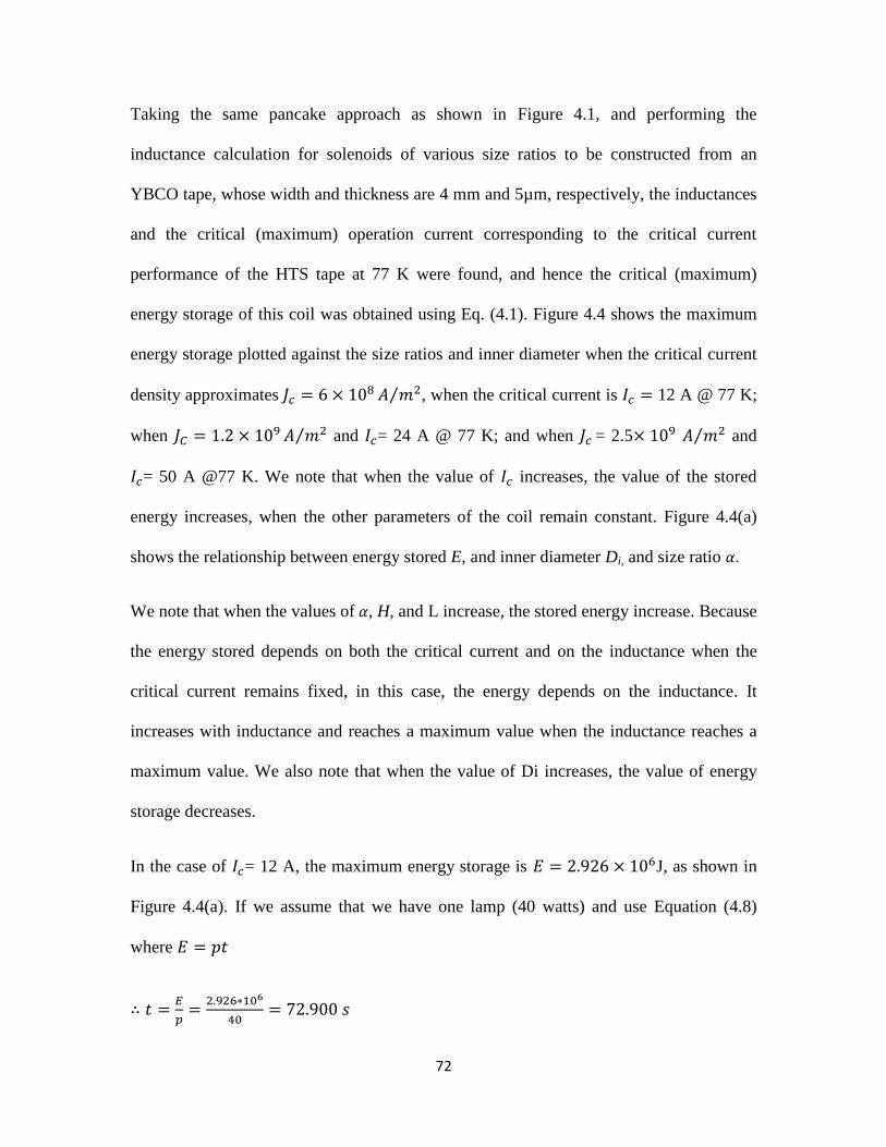
72
Taking the same pancake approach as shown in Figure 4.1, and performing the
inductance calculation for solenoids of various size ratios to be constructed from an
YBCO tape, whose width and thickness are 4 mm and 5µm, respectively, the inductances
and the critical (maximum) operation current corresponding to the critical current
performance of the HTS tape at 77 K were found, and hence the critical (maximum)
energy storage of this coil was obtained using Eq. (4.1). Figure 4.4 shows the maximum
energy storage plotted against the size ratios and inner diameter when the critical current
density approximates ⁄ , when the critical current is 12 A @ 77 K;
when ⁄ and = 24 A @ 77 K; and when = 2.5 ⁄ and
= 50 A @77 K. We note that when the value of increases, the value of the stored
energy increases, when the other parameters of the coil remain constant. Figure 4.4(a)
shows the relationship between energy stored E, and inner diameter Di, and size ratio
We note that when the values of , H, and L increase, the stored energy increase. Because
the energy stored depends on both the critical current and on the inductance when the
critical current remains fixed, in this case, the energy depends on the inductance. It
increases with inductance and reaches a maximum value when the inductance reaches a
maximum value. We also note that when the value of Di increases, the value of energy
storage decreases.
In the case of = 12 A, the maximum energy storage is 𝐸 J, as shown in
Figure 4.4(a). If we assume that we have one lamp (40 watts) and use Equation (4.8)
where 𝐸 𝑝
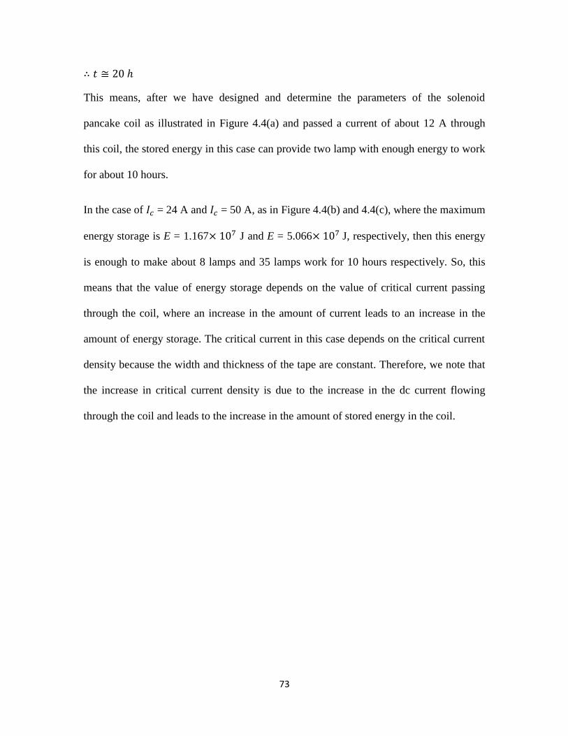
73
This means, after we have designed and determine the parameters of the solenoid
pancake coil as illustrated in Figure 4.4(a) and passed a current of about 12 A through
this coil, the stored energy in this case can provide two lamp with enough energy to work
for about 10 hours.
In the case of = 24 A and = 50 A, as in Figure 4.4(b) and 4.4(c), where the maximum
energy storage is E = 1.167 J and E = 5.066 J, respectively, then this energy
is enough to make about 8 lamps and 35 lamps work for 10 hours respectively. So, this
means that the value of energy storage depends on the value of critical current passing
through the coil, where an increase in the amount of current leads to an increase in the
amount of energy storage. The critical current in this case depends on the critical current
density because the width and thickness of the tape are constant. Therefore, we note that
the increase in critical current density is due to the increase in the dc current flowing
through the coil and leads to the increase in the amount of stored energy in the coil.
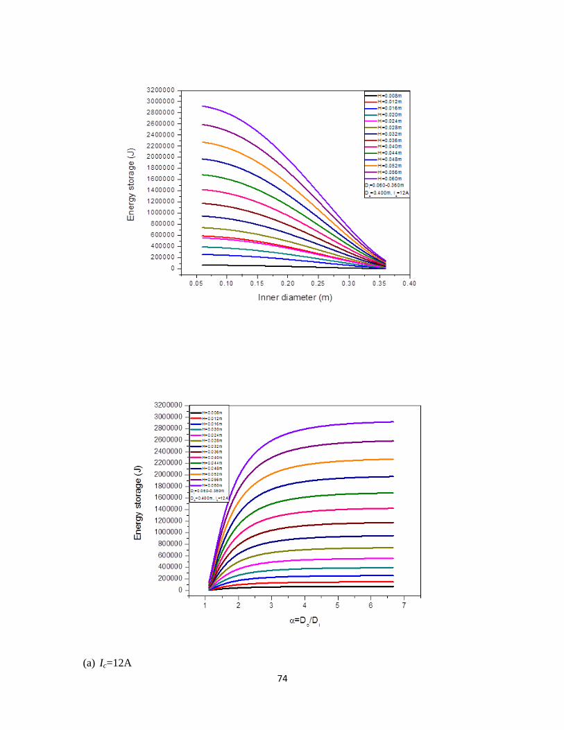
74
(a) Ic=12A
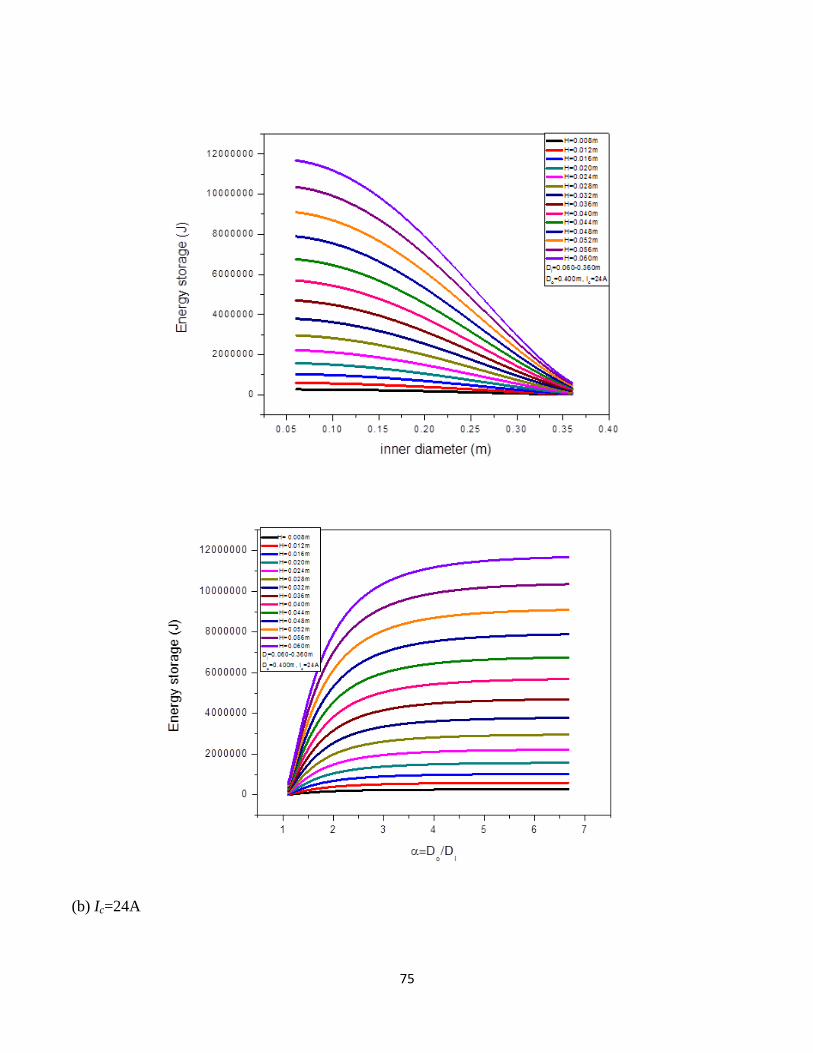
75
(b) Ic=24A
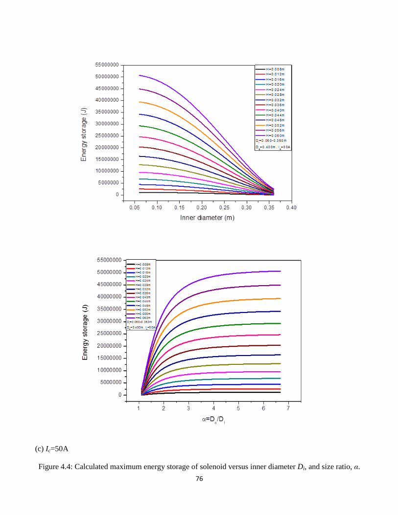
76
(c) Ic=50A
Figure 4.4: Calculated maximum energy storage of solenoid versus inner diameter Di, and size ratio, α.
77
Optimization of inner diameter of coil
Figure 4.5 indicates the relationship between height H and E the maximum energy
storage in the coil, when the inner diameter of the coil (Di) is constant and is increased by
different values for different curves. For each of these values, the inductance of the coil
was calculated using Equation (4.5), and the amount of the energy stored was calculated
using Equation (4.1). This was achieved using the Origin software program to graph the
relationship between H and E, when the outer diameter 𝐷 and Di were held constant and
the only variable in the equation was the height of the coil
It should be noted that energy storage increases as the height of the coil increases. It is
also the case that increasing the inner diameter leads to decrease energy stored.
Therefore, we can calculate the maximum energy that can be stored in the coil by
determining the value of because 𝐷 and Di is constant. Once this calculation has been
done, any further increase in Ic will be increase in the level of energy stored in the coil.
Figure 4.5: shows the relationship between height of the coil and maximum energy
storage when 𝐷 and, Di is constant and is variable.
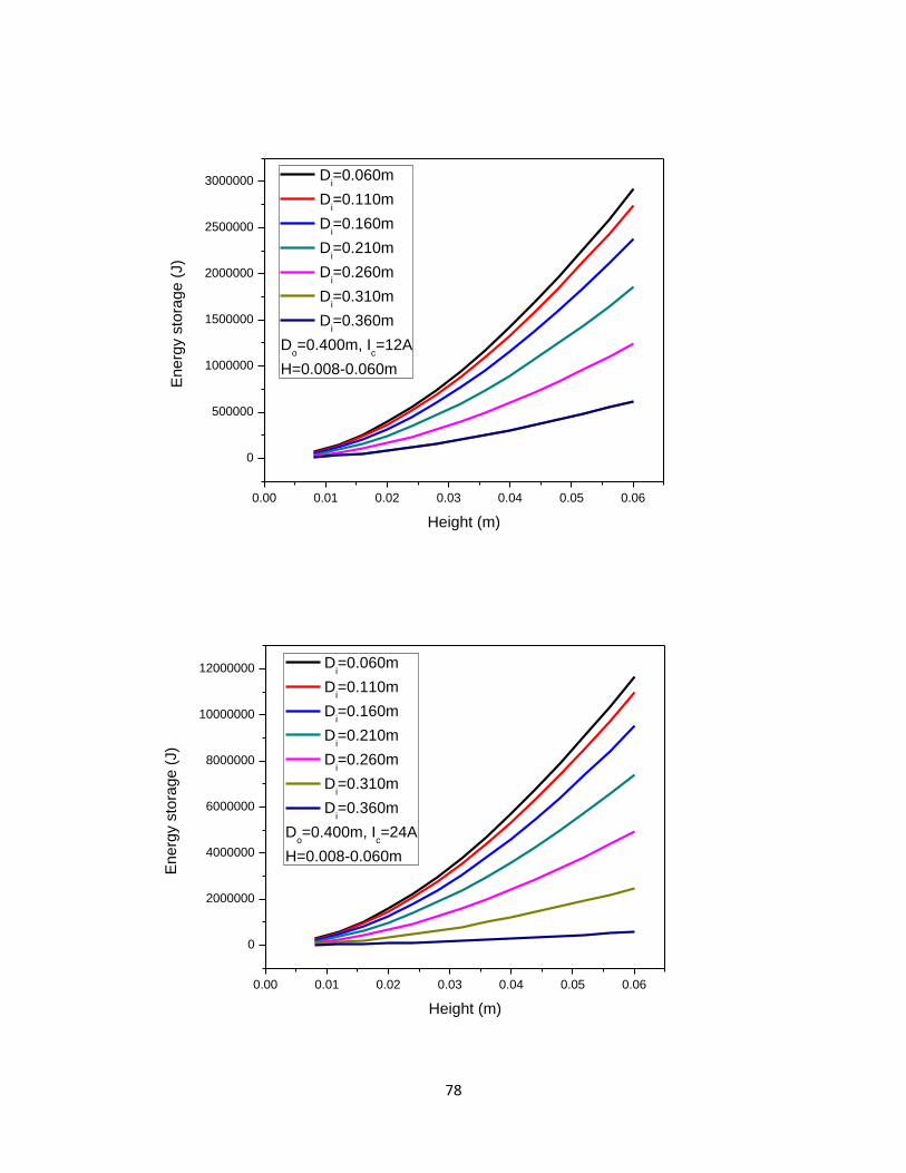
78
0.00 0.01 0.02 0.03 0.04 0.05 0.06
0
500000
1000000
1500000
2000000
2500000
3000000
Energ
y s
tora
ge (
J)
Height (m)
Di=0.060m
Di=0.110m
Di=0.160m
Di=0.210m
Di=0.260m
Di=0.310m
Di=0.360m
Do=0.400m, I
c=12A
H=0.008-0.060m
0.00 0.01 0.02 0.03 0.04 0.05 0.06
0
2000000
4000000
6000000
8000000
10000000
12000000
En
erg
y s
tora
ge
(J)
Height (m)
Di=0.060m
Di=0.110m
Di=0.160m
Di=0.210m
Di=0.260m
Di=0.310m
Di=0.360m
Do=0.400m, I
c=24A
H=0.008-0.060m
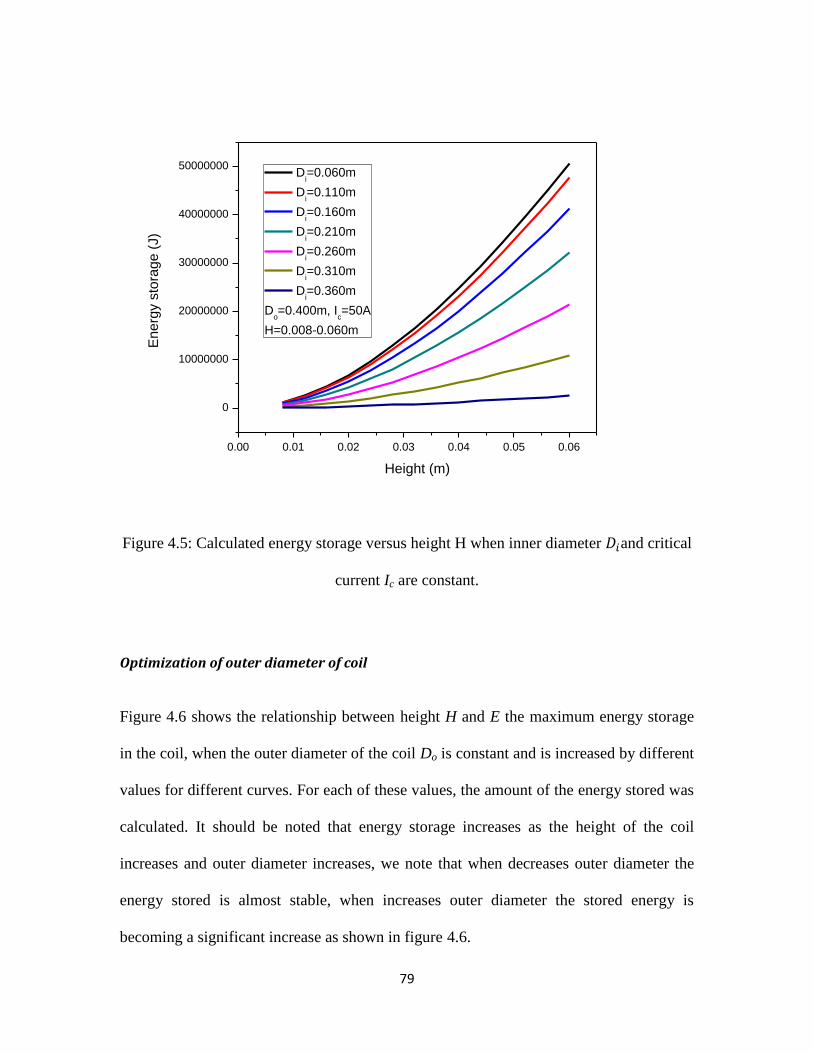
79
Figure 4.5: Calculated energy storage versus height H when inner diameter 𝐷 and critical
current Ic are constant.
Optimization of outer diameter of coil
Figure 4.6 shows the relationship between height H and E the maximum energy storage
in the coil, when the outer diameter of the coil Do is constant and is increased by different
values for different curves. For each of these values, the amount of the energy stored was
calculated. It should be noted that energy storage increases as the height of the coil
increases and outer diameter increases, we note that when decreases outer diameter the
energy stored is almost stable, when increases outer diameter the stored energy is
becoming a significant increase as shown in figure 4.6.
0.00 0.01 0.02 0.03 0.04 0.05 0.06
0
10000000
20000000
30000000
40000000
50000000
Energ
y s
tora
ge (
J)
Height (m)
Di=0.060m
Di=0.110m
Di=0.160m
Di=0.210m
Di=0.260m
Di=0.310m
Di=0.360m
Do=0.400m, I
c=50A
H=0.008-0.060m
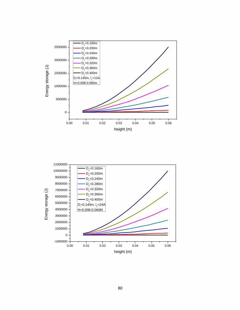
80
0.00 0.01 0.02 0.03 0.04 0.05 0.06
0
500000
1000000
1500000
2000000
2500000
Energ
y s
tora
ge (
J)
height (m)
Do=0.160m
Do=0.200m
Do=0.240m
Do=0.280m
Do=0.320m
Do=0.360m
Do=0.400m
Di=0.145m, I
c=12A
H=0.008-0.060m
0.00 0.01 0.02 0.03 0.04 0.05 0.06
-1000000
0
1000000
2000000
3000000
4000000
5000000
6000000
7000000
8000000
9000000
10000000
11000000
En
erg
y s
tora
ge
(J)
height (m)
Do=0.160m
Do=0.200m
Do=0.240m
Do=0.280m
Do=0.320m
Do=0.360m
Do=0.400m
Di=0.145m, I
c=24A
H=0.008-0.060M
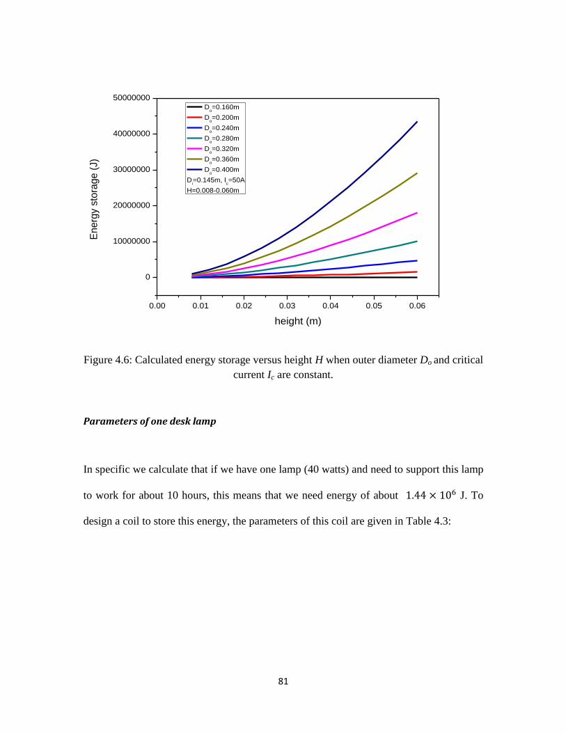
81
Figure 4.6: Calculated energy storage versus height H when outer diameter Do and critical
current Ic are constant.
Parameters of one desk lamp
In specific we calculate that if we have one lamp (40 watts) and need to support this lamp
to work for about 10 hours, this means that we need energy of about J. To
design a coil to store this energy, the parameters of this coil are given in Table 4.3:
0.00 0.01 0.02 0.03 0.04 0.05 0.06
0
10000000
20000000
30000000
40000000
50000000
E
ne
rgy s
tora
ge
(J)
height (m)
Do=0.160m
Do=0.200m
Do=0.240m
Do=0.280m
Do=0.320m
Do=0.360m
Do=0.400m
Di=0.145m, I
c=50A
H=0.008-0.060m
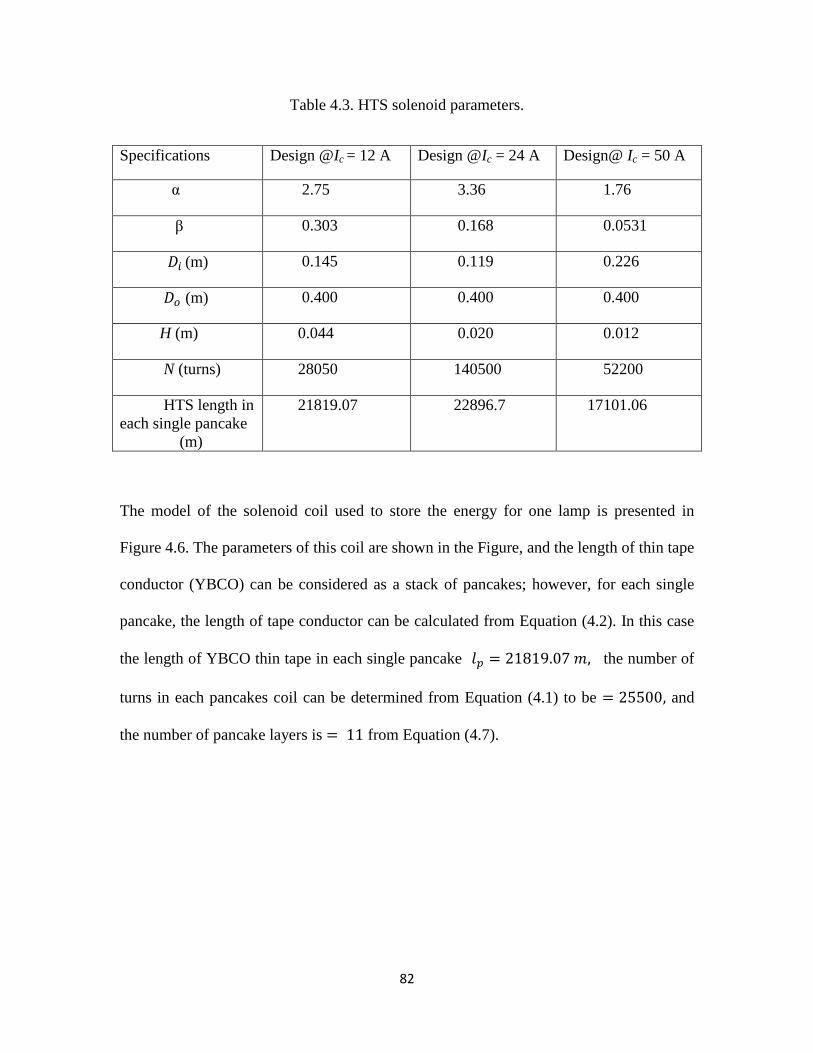
82
Table 4.3. HTS solenoid parameters.
Specifications Design @Ic = 12 A Design @Ic = 24 A Design@ Ic = 50 A
α 2.75 3.36 1.76
β 0.303 0.168 0.0531
𝐷 (m) 0.145 0.119 0.226
𝐷 (m) 0.400 0.400 0.400
H (m) 0.044 0.020 0.012
N (turns) 28050 140500 52200
HTS length in
each single pancake
(m)
21819.07 22896.7 17101.06
The model of the solenoid coil used to store the energy for one lamp is presented in
Figure 4.6. The parameters of this coil are shown in the Figure, and the length of thin tape
conductor (YBCO) can be considered as a stack of pancakes; however, for each single
pancake, the length of tape conductor can be calculated from Equation (4.2). In this case
the length of YBCO thin tape in each single pancake 𝑙 the number of
turns in each pancakes coil can be determined from Equation (4.1) to be and
the number of pancake layers is from Equation (4.7).
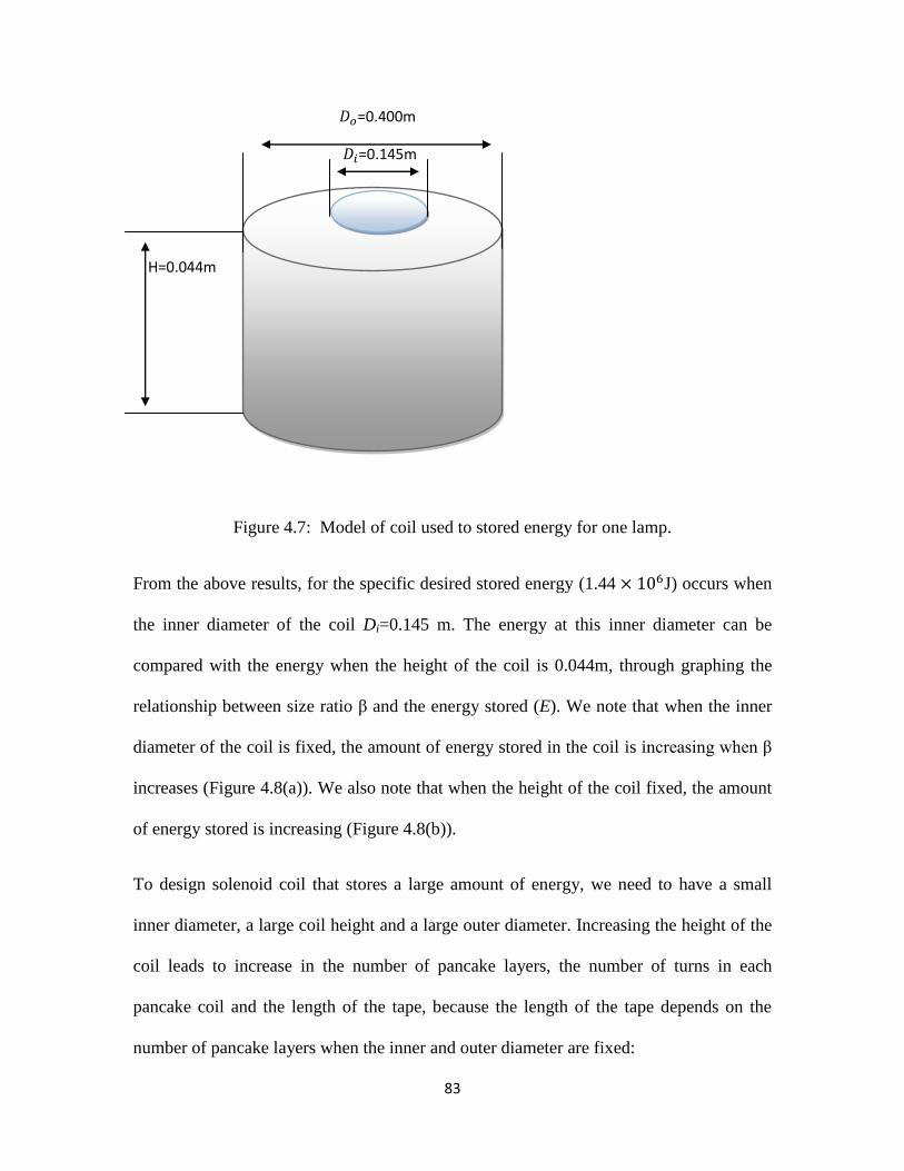
83
𝐷 =0.400m
𝐷 =0.145m
H=0.044m
Figure 4.7: Model of coil used to stored energy for one lamp.
From the above results, for the specific desired stored energy (1.44 J) occurs when
the inner diameter of the coil Di=0.145 m. The energy at this inner diameter can be
compared with the energy when the height of the coil is 0.044m, through graphing the
relationship between size ratio β and the energy stored (E). We note that when the inner
diameter of the coil is fixed, the amount of energy stored in the coil is increasing when β
increases (Figure 4.8(a)). We also note that when the height of the coil fixed, the amount
of energy stored is increasing (Figure 4.8(b)).
To design solenoid coil that stores a large amount of energy, we need to have a small
inner diameter, a large coil height and a large outer diameter. Increasing the height of the
coil leads to increase in the number of pancake layers, the number of turns in each
pancake coil and the length of the tape, because the length of the tape depends on the
number of pancake layers when the inner and outer diameter are fixed:
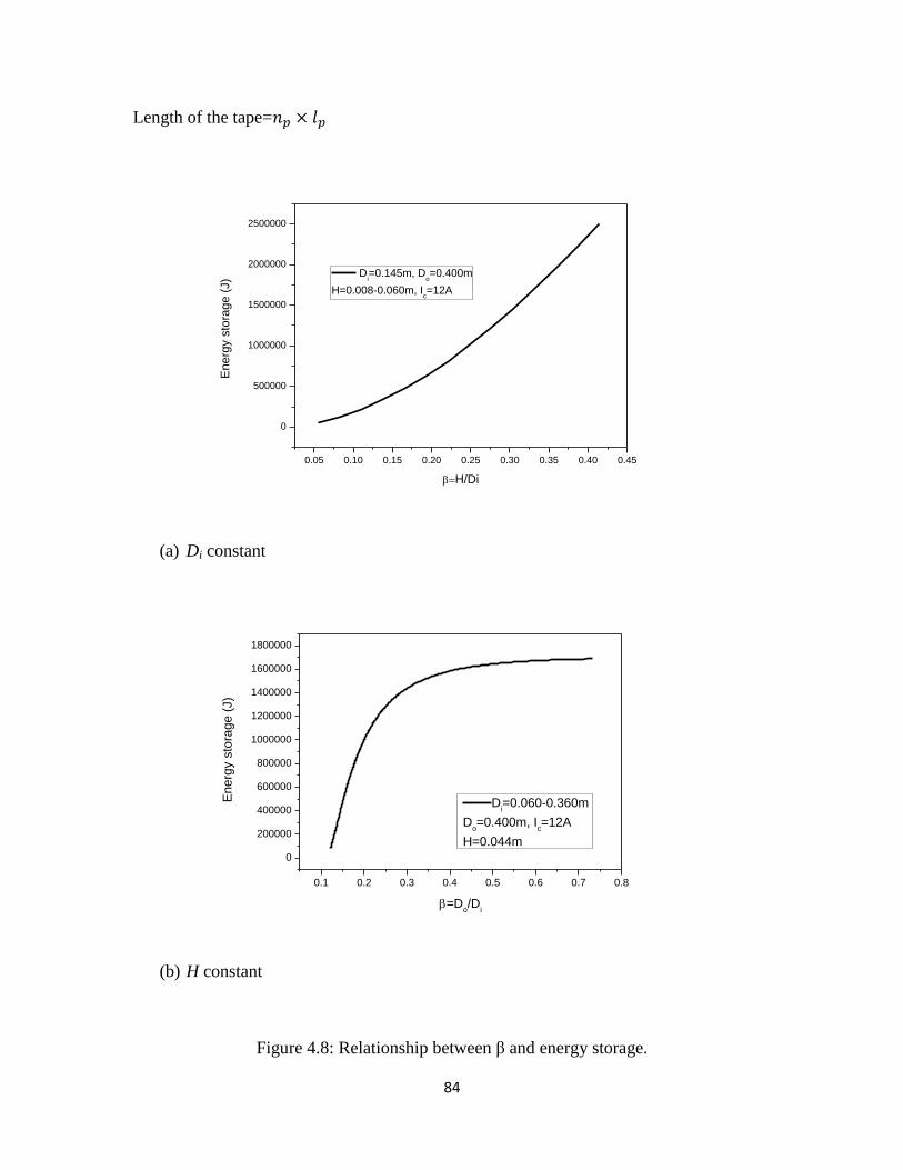
84
Length of the tape= 𝑙
(a) Di constant
(b) H constant
Figure 4.8: Relationship between β and energy storage.
0.05 0.10 0.15 0.20 0.25 0.30 0.35 0.40 0.45
0
500000
1000000
1500000
2000000
2500000
Energ
y s
tora
ge (
J)
H/Di
Di=0.145m, D
o=0.400m
H=0.008-0.060m, Ic=12A
0.1 0.2 0.3 0.4 0.5 0.6 0.7 0.8
0
200000
400000
600000
800000
1000000
1200000
1400000
1600000
1800000
En
erg
y s
tora
ge
(J)
=Do/D
i
Di=0.060-0.360m
Do=0.400m, I
c=12A
H=0.044m
85
It can be concluded that the energy is stored to a maximum value when a height of the
coil is large. In the case of a coil where the coil height which is associated with the
maximum stored energy given the fixed parameters or the length of the coil required for
the specific energy storage has been determined, further increasing the height of the coil
would lead to increased energy storage. This is because the relationship between the
height of coil (H) and size ratio β is a positive relationship, and the relationship between
the inner diameter (Di) and size ratios α and β an inverse relationship.
The relationship between the critical current and size ratio α is an inverse relationship and
depends on the amount of current flowing through the coil. When more current is applied,
it reduces the size ratio and increases the energy storage.
4.5 Summary
In conclusion, second-generation high temperature superconducting (2G HTS) wire made
from YBCO coated conductor has great potential for commercialization and utilization as
an engineering conductor for many real world applications.
This study presents the design of a solenoid YBCO pancake coil; this design gives the
maximum stored energy in the coil. We have calculated this energy through using the
energy storage equation, after determining the parameters of this coil, such as, outer and
inner diameters of the coil, height of the stack of pancakes, and number of turns of the
coil, by calculating the number of pancake layers and the number of the turns in each
pancake, along with the maximum inductance of the coil. Also, the critical current
86
flowing through the coil was calculated by determining the critical current density and
parameters of the tape width and thickness.
In this thesis, this design for a pancake coil is capable of storing energy of about 1.4 MJ,
and this energy is sufficient to power one desk lamp (40 watts) working for about 10
hours straight. The parameters of this coil are as follows: outer diameter (Do) = 0.400 m,
inner diameter (Di) = 0.145 m, height of stack of pancake (H) = 0.044 m, number of turns
of solenoid (N) = 280500, number of turns in each pancake = 25500, number of pancake
layers = 11 For an HTS solenoid for energy storage purposes, the method of design
optimization is to obtain the maximum energy storage for a given length of
superconductor. In this case the length of tape in each single pancake was about 21819.07
m, and the critical current at 77 K, self- field was 12 A. When designing an optimization
solenoid coil to store a large amount of energy, this energy will depends on critical
current and inductance. If the critical current value is selected and installed, thus, the
value of the energy stored depends on the inductance, which depends on the parameters
of the solenoid coil. Figure 4.2(b) shown the best α range for this optimization is
probably somewhere between 1.5-3, the energy stored at these values are increasing ,
after that the energy begins to stabilize and any increase in any parameters do not have a
significant impact in the energy levels. Also, if Do and Di are decreasing, while H is
increasing, there would be optimal values for H and Do and Di providing the highest
stored energy as shown in figure 4.5 and 4.6 respectively. When the value of Do and Di
are small, the amount of energy stored in the coil remains the same. Therefore, the
optimal values for H are between 0.020 m and 0.060m. Also, in figure 4.8 the best β
range for this optimization is between 0.15 and 0.40.
87
Future work includes testing this coil at liquid nitrogen temperature, in addition to
studying the cooling system (refrigeration) and cost efficiency of this system.
88
Chapter 5 Conclusion.
Smaller HTS SMES have been found to be successful in meeting specific applications in
several areas such as ground based power supply sources in difficult areas such as the
Arctic for air force applications, etc. Also, the cost of these SMES systems has been
drastically pulled down by using applications such as liquid nitrogen based refrigeration
systems rather than expensive helium based refrigerator systems. They are now available
in smaller sizes such as 1 kWh to 1 MWh and are successfully being used.
This thesis presents a SMES solenoid coil which has been designed for a closed system.
The design gives the maximum stored energy in the coil, which has been wound from a
certain length of second-generation high-temperature superconductor (2GHTS) YBCO
coated conductor. Design optimization for the solenoid constructed from HTS thin film
can be achieved theoretically. A solenoid pancake coil offers the maximum inductance
for a given length of HTS. The energy storage of a solenoid constructed a given length of
HTS can also be maximized by choosing the proper size ratios. The dimensional
outcome, however, will depend on the critical current performance of the HTS in external
magnetic field at the operation temperature. For some HTS operating at certain
temperatures, the optimal design could be impractical, and a compromise solution can be
found by balancing various practical factors.
SMESs, which are a non-negligible force in national economic development, are now
smaller in size and more flexible in form, and can rapidly respond to market changes to
meet the ever-growing and diversified social consumption demands, while promoting the
coordination of large-scale social production based on specialization. Moreover, SMESs

89
could drive the high-speed development of municipal economies and play a unique role
in creating jobs, invigorating markets, improving people's lives, and maintaining social
stability. Large-scale enterprises need services from SMESs in order to achieve rapid
development, and their supplementation and coordination will accelerate the development
of the modern economy.
90
References
Ali, M, Wu, B and Dougal, R (2010), “An overview of SMES applications in power and
energy systems”, IEEE Transactions on Sustainable Energy, vol. 1, no. 1, pp. 38-47.
Application of superconductivity technology, Sumitomo Electric Industries Ltd.
Retrieved from http://global-sei.com/super/about_e/application.html
AP Johnstone, Y Yang, C Beduz (2005), “Thermal stability and quench propogation in a
cryocooler-cooled pancake coil of BI2223 tape operating between 35 K-65 K”,
Proceeding of ICEC20, pp. 697-700.
Akhil, A. A, Butler, P and Bickel, T. C. (1993), “Battery energy storage and
superconducting magnetic energy storgy for utility applications” A Qualitative analysis,
Sandia National Laboratories, USA.
Bhattacharya. D, S. Harkness, S. J. Narayan, P. Diwari, Jahncke, Catherine, Sparks, R.
Paesler, M (1991), “Excellent thermal stability of superconducting properties in
YBa2Cu3O7 films irradiated by pulsed excimer lasers”, Journal of Applied Physics, vol.
59, no.11, pp. 1380-1382.
Boom, R and Peterson, H (1972), “Superconductive energy storage for power systems”,
Intermag Conference, pp. 701-703.
Buckel.W (1999), “Superconductivity, fundamentals and applications”, VCH, Weinheim,
Germany.
Buzdin and I. Baladie (2002), “Attraction between pancake vortices in the crossing
lattices of layered supercoductors”, Physical Review Letters, vol. 88, no. 14, pp. 147001-
1470014.
Chen. L, Y. Liu, A. B. Arsoy, M. Steurer and M. R. Iravani (2006), “Detailed Modeling
of superconducting magnetic energy storage (SMES) system”, IEEE Transactions on
Power Delivery, vol. 21, no. 2, pp. 699-710.
91
Choi, S, Bae, J, Kim, W, Park, C, Lee, S and Choi, K (2009), “A conceptual design of a
conduction-cooled magnet for a superconducting property measurement system”, IEEE
Transaction on Applied Superconductivity, vol. 19, no. 3, pp. 1249-1252.
Connolly, D (2010), “A review of energy storage technologies: for the integration of
flucting renewable energy”, University of Limerick.
Cooley L, Xueyan Sung (2003), “Improved flux pinning with the inclusion of
intermetallic clues from MgB2 and MgCNi3”, IEEE Transaction on Applied
Superconductivity, vol. 13, no. 2.
Dew-Hughes. D (2001) “The critical current of superconductors: an historical review”,
American Institute of Physics, vol. 27, no. 9-10, pp. 713-722.
Dincer. Sezai. M and M. Timur Aydemir Superconducting Inductive Coils, Energy
Storage Systems, Encyclopedia of Life Support Systems (EOLSS), vol. II, pp. 1-9.
Feng, ZX (1988), “Optimization of superconducting solenoid coil”, IEEE Transaction on
Magnetics, vol. 24, no. 2, pp. 926-292.
Flik MI, Tien CL (1990),” Intrinsic thermal stability in superconducting materials”,
Transactions of the ASME, vol. 112, no. 1, p. 10.
Fujiwara. N, H. Hayashi, S. Nagaya, Y. Shiohra (2010), “Development of YBCO power
devices in Japan”, Physica C, vol. 470, pp. 980-985.
Guomin Zhang, Shaotao Dai, Naihao Song, Zhiqin Zhu, Jingye Zhang, Wenyong Guo,
Dong Zhang, Zhifeng Zhang, Liye Xiao and Liangzhen Lin (2011), “The construction
progress of a high-Tc superconducting power substation in China”, IEEE Transaction on
Applied Superconductivity, vol. 21, no. 3, pp. 2824-2827.
.
Hazelton. D. W and V. Selvamanickam (2009), “Superpower’s YBCO coated high-
temperature superconductong (HTS) wire and magnet applications”, IEEE, vol. 97, no.
11, pp. 1831-1836.
92
Hoon Kim Ji, Woo-Seok Kim, Song-Yop Hahn, Jae Moon Lee, Myung Hwan Rue, Bo
Hyung Cho, Chang Hwan Im, and Hyun Kyo Jung (2005), “Characteristic test of HTS
pancake coil modules for small-sized SMES”, IEEE Transactions on Applied
Superconductivity, vol. 15, no. 2, pp. 1919-1922.
Ise, T and Murakami, Y (1994), “Modular based design for a small to medium scale
toroidal type SMES”, Transaction on Applied Superconductivity, vol. 4, no. 2, pp. 51-55.
Joe Khachan and Stephen Bosi, “Superconductivity”.
Ju Wen, Jian X. Jin, Yin, You G. Guo, and Jian G. Zhu (2007), “Theory and application
of superconducting magnetic energy storage”.
Kittel, C, (2005) “Introduction to solid state physics”, 8th
ed. University of California
Berkeley, John Wiley & Sons. Inc.
Kim. J. K, W. S. Kim, S. Y. Hahn, J. M. Lee, M. H. Rue, B. H. Cho, C. I. Hwan, H and
K. Jung (2005), “Characteristic test of HTS pancake coil modules for small-sized
SMES”, IEEE Transaction on Applied Superconductivity, vol. 15, no. 2, part 2, pp. 1919-
1922.
Kolluri. S (2002), “Application of distributed superconducting magnetic energy storage
system (D-SMES) in the energy system to improve voltage stability”, IEEE, vol. 2, pp.
838-841.
Marcel Gustavo Molina, Pedro Envigue Mercado and Edson Hirokazu Watanabe (2011),
“Improved superconducting magnetic energy storage (SMES) controller for high-power
utility applications”, IEEE Transaction on Energy Conversion, vol. 26, no. 2, pp. 444-
456.
Martinez. E, L A Angurel, J. Pelegrm, YY. Xie, V. Selvamanickam (2010), “Thermal
stability analysis of YBCO coated conductors subject to over-currents”, Superconductor
Science and Technology, vol. 23.025011, pp. 8.
Masuda, M. and Shintomi, T (1977), Superconducting magnetic energy storage,
Cryogenics, pp. 607-612.
93
Myung-Jin Park, Sang-Yeop Kwak, Woo-Secok Kim, Seung-Wook Lee, Ji-Kwang Lee,
Kyeong-Dal Choi, Hyun-Kyo Jung, Ki-Chul Seong and Song-Yop Hahn (2007), Analysis
of magnetic field distribution and AC losses of a 600 KJ SMES, Cryogenics, vol. 47, pp.
391-396.
NMR Spectroscopy, n. d, Non superconducting magnet system, accessed August 2012, R
http://intermediateorgchemistry.co.uk/nmr.htm.
Okuno. K , A Shikov, and Nkoizumi (2004), “Superconducting magnet system infusion
reactor”, Journal of Nuclear Materials, vol. 329-333, part A, pp. 141-147.
Okuba. T (2000), “Size and arrangement effect of Nb artificial pinning centres on flux
pinning in Nb-Ti multifilamentary wires”, IEEE Transaction on Applied
Superconductivity, vol. 10, no.1.
Padimiti, D and Chowdhury, B (2007), “Superconducting magnetic energy storage
system for improved dynamic system performance”, IEEE, PP. 1-6.
Pan, A, Pysarenko, S and Dou, S (2006), “Drastic improvement of surface structure and
current-carrying ability in YBa2Cu3O7 by introducing multilayered structure”, Applied
Physics, vol. 88, pp. 232506-1-232506-3.
Poole, Charles P. Farach, Horacio A, Creswick, Richard J (2007), “Superconductivity”,
Academic press, Amsterdam, NLD, pp. 671.
Rao. Vasudeva. V (2008), “Superconducting magnetic energy storage and applications”,
American Institute of Physics, 978-0-7354-0593-0108, pp. 393-408.
Rodrigues, C. A (2007), “Flux pinning behavior of Nb3Sn superconductors with
nanostructured pinning centers”, IEEE Transactions of Applied Superconductivity,vol.
17, no. 2, pp. 2627-2630
Rupich, M, Li, X, Thieme, C, Sathyamurthy, S, Fleshler, D, Thompson, E, Schreiber, J,
Lynch, J, Buczek, D, DeMoranville, K, Inch, J, Cedrone, P and Slack, J (2010),
“Advances in second generation high temperature superconducting wire manufacturing
94
and R & D at American superconductor corporation”, Superconductor Science and
Technology, vol. 23, pp. 1-9.
Selichi Kondo (1992), “Superconducting characteristics and the thermal stability of
tungsten-based amorphous thin films”, Journal of Materials Research, vol. 7, no. 04, pp.
853-860.
So Noguchi, Hido Yamashita, and Atsushi Ishiyama (2003), “An optimization method for
design of SMES coils using YBCO tape”, IEEE Transaction on Applied
Superconductivity, vol. 23, no. 2, pp. 1856-1859.
So Noguchi and Makoto Tsuda (2010), “An optimal configuration design of
superconducting magnets with HTS tapes for DC reactor”, IEEE Transactions on Applied
Superconductivity, vol. 20, no. 3, pp. 1-4.
Sutanto, D and Cheng, KWE (2009), Superconducting magnetic energy storage systems
for power system applications, Proceedings of 2009 IEEE International Conference on
Applied Superconductivity and Electromagnetic Devices, pp. 377-380.
The energy lab, Energy storage technology overview. Retrieved from
http://www.netl.doe.gov/technologies/coalpower/fuelcells/seca/tutorial/TutorialII_files/T
utorialII.pdf.
Therond, P, G. Jolt, I, Volker, M (1993), “Supercoducting magnetic energy storage
SMES for industrial applications comparision with battery systems”, IEEE Transactions
on Applied Superconductivity, vol. 3, no. 1, pp. 250-253.
Tixador. P, B. Bellin, M. Deleglise, J. C. Vallier, C. E. Bruzek, S. Pavard and J. M.
Saugrain (2005), “Design of a 800 KJ HTS SMES”, IEEE Transactions of Applied
Superconductivity, vol. 15, no. 2, pp. 1907-1910.
U. Atznony, L. H. Bennett, and L. J. Swartzendruber (1995), “Is there a paramagnetic
Meissner-Ochsenfeld effect?”, IEEE Transactions on Magnetics, vol. 31, no. 6, pp. 4118-
4120.
95
Venkataratnam. K, V. V. Rao, K. N. V. Subba Rao and A. Arun Kumar (1999),
“Optimum design of superconducting magnet coil for a micro SMES unit”, IEEE
Transactions of Applied Superconductivity, vol. 9, no. 2, pp. 350-353.
Vinod. K, R G Abhilas Kumar and U Syamaprasad (2006), “Prospect for MgB2
superconductors for magnet application”,Superconductor Seience and Technology, vol.
20, no. 1.
Welsby. G. V (1960), “The theory and design of inductance coils”, Macdonald London,
John Wiley and Sons, Inc.
Weijia Yuan, A. M. Campbell, and T. A. Coombs (2009), “A model for calculating the
AC losses of second-generation high temperature superconductor pancake coils”,
Superconductor Science Technology, vol. 22 (075028), pp. 12.
Weijia Yuan, A. M. Campbell, and T. A. Coombs (2010), “Design and modeling of a
SMES coil”, 9th
Europen Conference on Applied Superconductivity (EUCAS), pp. 1-7.
Xue.D. X, K. W. E. Cheng and D. Sutanto (2005), Power System Applications of
Superconducting Magnetic Energy Storage Systems, IEEE, pp. 1524-1529.
Xie, Y, Marchevsky, M, Gogia, B, Knoll, A, Selvamanickam, V, Pethuraja, G, Chen, Y and, Lenseth, K (2009), Second generation HTS conductor design and engineering for electrical power applications, IEEE Transactions on Applied Superconductivity, 19(3), pp. 3009-3013.
Yeom, H. K. Hong, Y, J. Park, S, J. Seo, T. B. Seong, K, C and Kim, H, J (2007), “Study
of cryogenic conduction cooling systems for an HTS SMES”, Applied Superconductivity,
IEEE Transactions, vol. 17, no. 2, pp. 1955-1958.
Yi, H, P, Song, X, H, Liu, L. Liu, R. Zong, J. Zhang, J. S. Alamgir, A, K, M. Liu, Q.
Han, Z and Zheng, Y, K (2005), “Development of HTS BSCCO wire for power
applications”, IEEE Transaction on Applied Superconductivity, vol. 15, no. 2, pp. 2507-
2509.
96
Yi-Yuan Xie, Maxim Marchevsky, Xun Zhang, Kenneth Lenseth, Yimin Chen, Xuming
Xiong, Yunfei Qiao, Andrei Rar, Balvinder Gogia, Robert Schmidt, Allan Knoll, Venkat
Selvamanickam, Gopal Ganesan Pethuraja, and Partha Dutta (2009), “Second-generation
HTS conductor design and engineering for electrical power applications”, IEEE
Transactions on Applied Superconductivity, vol. 19, no. 3, pp. 3009-3013.
Yuan, W, Campbell, AM and Coombs, TA (2010), “Design and modeling of a SMES
coil”, Journal of Physics, Conference Series, vol. 234, pp. 1-7.
Yuan, W. Coombs, T. A, Kim, J. H, Kim, C. H, Kvitkovic, J and Pamidi, S (2011),
“Measurements and calculations of transport AC loss in second generation high
temperature superconducting pancake coils”, Journal of Applied Physics, American
Institute of Physics, 110,113906. pp. 1-5.
Yuichi Yamada, Masaharu Mogi and Ken-ichi Sato (2007), “Examples and future
prospects of high-temperature superconductor products”, Electric Wire & Cable, Energy,
SEI Technical Review, no. 65, pp. 51-59.
Zheng Li and Ma Weixin (2000), “Application of SMES system with a comprehensive
control for enhancing transient stability”, Advances in Power System Control, Operation
and Management, APSCOM, pp. 225-229.

97

98