Embed Size (px)
Citation preview

REFRIGERATION OF LOW-TEMPERATURE SUPERCONDUCTING COILS FOR NUCLEAR FUSION
R. ZANINO AND L. SAVOLDI RICHARD Dipartimento di Energetica, Politecnico 24 c. Duca degli Abruzzi, I-10129 Torino ITALY E-mail: [email protected], [email protected]
1. Introduction In this work, the main issues concerning the refrigeration of low critical temperature superconducting (SC) coils for nuclear fusion are presented, with particular emphasis on the strong interrelation between the experimental R&D needs and the development of computational tools suitable for the analysis of these complex systems. Beginning with an overview of the components of the magnet system in a nuclear fusion machine, we then summarize the major design features and peculiarities of the conductors from which these coils are wound. Some thermo-physical properties of different materials utilized in these coils (solids, e.g., Nb3Sn, Cu, SS and fluids, typically He) are mentioned, which have a role in the evolution of thermal-hydraulic transients. We then discuss some of the main results of the experimental campaigns performed on prototype coils during the last few years, with an emphasis on the assessment of superconductor critical properties and of the performance of these coils, and compare them with the results of numerical simulations, with special reference to the computational tools developed at Politecnico di Torino. Finally, a few open problems are discussed.
One of the two methods of confinement of a fully ionized gas (i.e., a plasma), which can be conceivably realized in nuclear fusion machines, relies on the magnetic field produced by a suitable set of coils in a toroidal geometry (the other method currently used – inertial confinement – is beyond the scope of this review). In the case of the International Thermonuclear Experimental Reactor (ITER) project, the machine is of the so-called tokamak type, with the field resulting from the superposition of three components, originated respectively by the central solenoid (CS) – a pulsed coil equivalent to the primary circuit of a transformer whose secondary is the plasma itself, the set of toroidal field (TF) coils – located on vertical planes through the symmetry axis of the machine, and the set of poloidal field (PF) coils – located on horizontal planes, see Fig.1.
In a reactor these coils will carry very high currents (typically several tens of kA) in order to produce high fields (typically several T) and therefore must be superconducting in order to reduce the losses in the system, i.e. the heat load on the cryogenic system. (Notice that a few of the present-day tokamaks are SC, e.g. Tore Supra at CEA Cadarache, France, but they are of much smaller size and performance than a reactor will be. On the other hand, nuclear fusion reactors, capable of self-

2
sustaining the energy balance, are still only on paper). Different SC materials are available but the combination of high current and field, together with the resulting high electro-mechanical load, and the complex manufacturing requested by the coil geometry, reduce them to the traditional low critical temperature (TC) superconductors [1], while the more recent high-TC materials are at present restricted to specific components (e.g. the current leads) of the ITER magnet system.
Figure 1. Sketch of ITER
The typical operating temperature T = Top ~ 4-6 K requires helium as a coolant [2].
In most applications, and in particular in ITER, supercritical HeI is used at operating pressure pop ~ 0.5-0.6 MPa, in forced circulation (as opposed to, e.g., high-field superconducting magnets used in other large-scale applications as particle accelerators, which are typically cooled in HeII baths at nearly atmospheric pressure).
The conductors used for the ITER magnets are so-called cable-in-conduit conductors (CICC). The current flows in the bundle of SC (and possibly Cu) strands. At T < TCS (the so-called current sharing temperature) all current flows in the SC; for TCS < T < TC a fraction of the current flows also in the Cu, leading to Joule power generation; at T > TC all of the current flows in the Cu. The helium circulates both in the annular cable bundle region, and in a central cooling channel, with far lower hydraulic impedance than the cable region and separated from it by a perforated helix, see Fig.2. The central channel is needed/useful because the hydraulic length of a conductor in the ITER coils can easily exceed several hundred m, so that for the same total mass flow

3
rate it decreases the pumping work, which is a very significant part of the cryogenic load. Typical conductors used in the ITER Model Coils are shown in Figs.3-4. The peculiar dual-channel topology of the ITER CICC has led in the recent past to a number of studies and developments, which will also be recalled here to some extent.
The generic coil may be wound according to different techniques (e.g., one-in-hand vs. two-in-hand, or layer-wound vs. pancake-wound). In all cases, up to ~ 100 m long conductors are jointed to other conductors electrically in series, the joint being a delicate resistive component with several designs of its own (e.g., lap-type vs. butt-type, or praying-hands vs. shaking-hands). The single conductors will typically be hydraulically in parallel, in order to minimize the pressure drop across the coil and to guarantee proper refrigeration and optimal temperature profile in the coil.
Figure 2. ITER CSMC dual-channel CICC
Figure 3. TFMC conductor cross section (courtesy of R.Maix)
Figure 4. CSMC conductor cross section (courtesy of JAERI)

4
TABLE I. Summary of recent experimental tests of SC magnets for nuclear fusion
Jacket NAME Design Test Features Superconductor Material Cross-
section QUELL
[3] EU/J/RUS/US 1996, Sultan,
PSI Villigen (CH)
SSSC Nb3Sn Ti Circular
USP MIT 1998, MIT LTJ (CSMC) Nb3Sn Incoloy Square FSJS CEA 1999, Sultan,
PSI Villigen (CH)
LTJ (TFMC) Nb3Sn -- --
CSMC [4]
J/US 2000, JAERI Naka (J)
MC (18 layers)
Nb3Sn Incoloy Square
CSIC [5] J 2000, JAERI Naka (J)
SFSC insert Nb3Sn Incoloy Square
TFMC (I) [6]
EU 2001, TOSKA, FZ
Karlsruhe (D)
MC (5 double pancakes on radial plates)
Nb3Sn SS Circular
TFCI [7] RUS 2001, JAERI Naka (J)
SFSC insert Nb3Sn Ti Circular
Nb3Al [8] J 2002, JAERI Naka (J)
SFSC insert Nb3Al SS Circular
TFMC (II) EU 2002, TOSKA, FZ
Karlsruhe (D)
Test with LCT
background coil
Nb3Sn SS Circular
PFCI EU 2004, JAERI Naka (J)
SFSC insert NbTi SS Square
SSSC = single sub-size conductor; LTJ = lap-type joint; MC = model coil; SFSC = single full-size conductor 2. The Role of Thermophysical Properties at Cryogenic Temperatures in the
Refrigeration of Superconducting CICC during Transients SC coils are subject to heat loads that may be both of generic nature (e.g., AC losses [1] due to magnetic field variation in time, inter-strand friction, etc.) or directly related to the nuclear fusion environment (e.g. neutrons from the reactor chamber reaching the coil). While some of these may contribute to the steady-state load, most of them are of transient nature. From the thermodynamic point of view, it is important to notice in this respect that He dominates the heat capacity (J/m3K) of the cable at Top, by a factor of about 50-500 with respect to SS and Cu, respectively.
Present-day tests of conductor/coil for the reactor simulate the real operation loads by using (resistive and/or inductive) heaters, and the refrigeration of the coil should be designed such as to maintain it in the superconducting state. When this is not the case, a potentially dangerous situation of thermal-hydraulic instability of the system establishes, called a quench, where the Joule power generated in the normal conducting zone exceeds the power extracted by the coolant. The normal zone can grow together with temperature and pressure in the coil until voltage sensors detect the event and the current is dumped. The event is typically of quickly divergent nature as the electrical resistivity of Cu is constant below ~ 20 K but then increases with a high power of T.
5
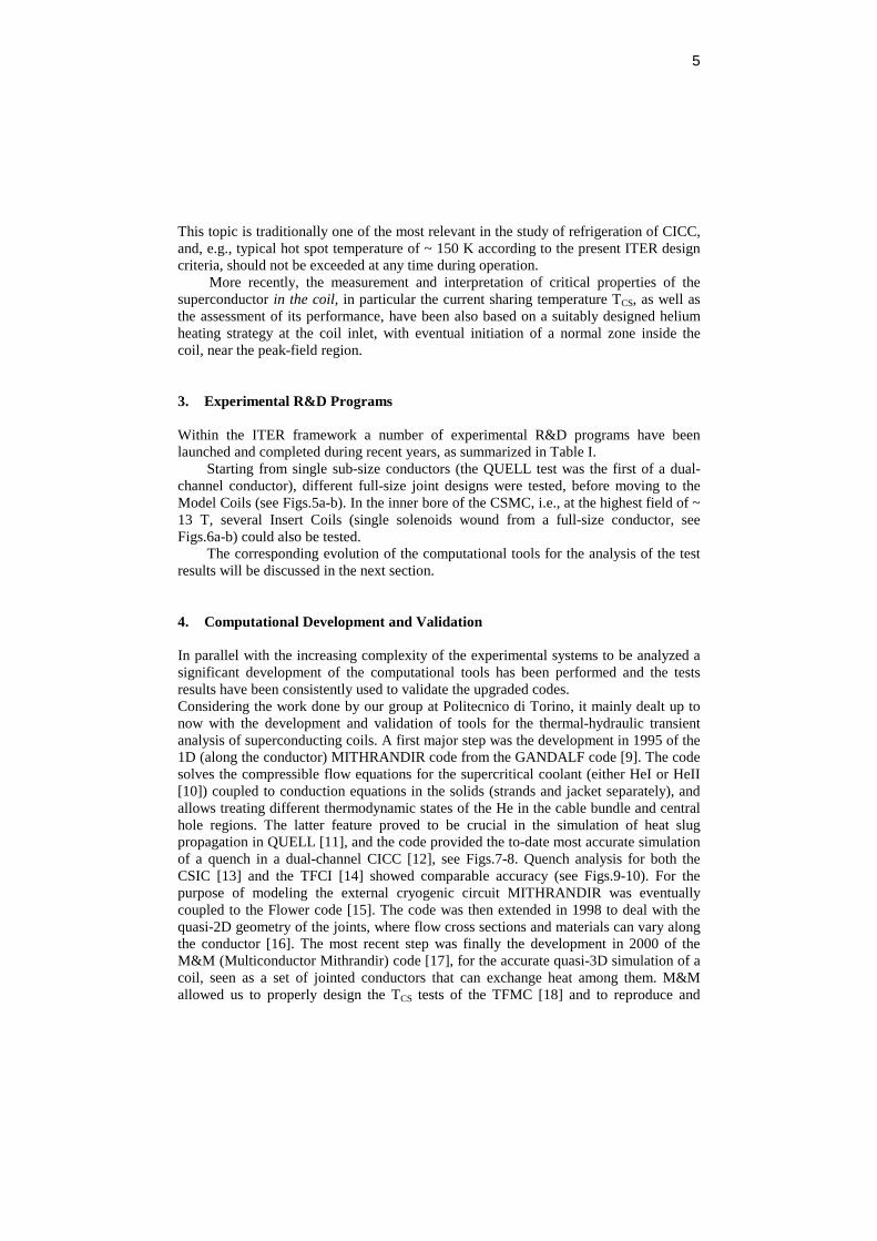
This topic is traditionally one of the most relevant in the study of refrigeration of CICC, and, e.g., typical hot spot temperature of ~ 150 K according to the present ITER design criteria, should not be exceeded at any time during operation.
More recently, the measurement and interpretation of critical properties of the superconductor in the coil, in particular the current sharing temperature TCS, as well as the assessment of its performance, have been also based on a suitably designed helium heating strategy at the coil inlet, with eventual initiation of a normal zone inside the coil, near the peak-field region. 3. Experimental R&D Programs Within the ITER framework a number of experimental R&D programs have been launched and completed during recent years, as summarized in Table I.
Starting from single sub-size conductors (the QUELL test was the first of a dual-channel conductor), different full-size joint designs were tested, before moving to the Model Coils (see Figs.5a-b). In the inner bore of the CSMC, i.e., at the highest field of ~ 13 T, several Insert Coils (single solenoids wound from a full-size conductor, see Figs.6a-b) could also be tested.
The corresponding evolution of the computational tools for the analysis of the test results will be discussed in the next section.
4. Computational Development and Validation In parallel with the increasing complexity of the experimental systems to be analyzed a significant development of the computational tools has been performed and the tests results have been consistently used to validate the upgraded codes. Considering the work done by our group at Politecnico di Torino, it mainly dealt up to now with the development and validation of tools for the thermal-hydraulic transient analysis of superconducting coils. A first major step was the development in 1995 of the 1D (along the conductor) MITHRANDIR code from the GANDALF code [9]. The code solves the compressible flow equations for the supercritical coolant (either HeI or HeII [10]) coupled to conduction equations in the solids (strands and jacket separately), and allows treating different thermodynamic states of the He in the cable bundle and central hole regions. The latter feature proved to be crucial in the simulation of heat slug propagation in QUELL [11], and the code provided the to-date most accurate simulation of a quench in a dual-channel CICC [12], see Figs.7-8. Quench analysis for both the CSIC [13] and the TFCI [14] showed comparable accuracy (see Figs.9-10). For the purpose of modeling the external cryogenic circuit MITHRANDIR was eventually coupled to the Flower code [15]. The code was then extended in 1998 to deal with the quasi-2D geometry of the joints, where flow cross sections and materials can vary along the conductor [16]. The most recent step was finally the development in 2000 of the M&M (Multiconductor Mithrandir) code [17], for the accurate quasi-3D simulation of a coil, seen as a set of jointed conductors that can exchange heat among them. M&M allowed us to properly design the TCS tests of the TFMC [18] and to reproduce and

6
interpret the results of the Model Coil tests [19, 20], see Figs.11-14. The present status of validation of the Mithrandir/M&M chain of codes is summarized in Table II, and allows us to claim that the Mithrandir/M&M codes are presently the most validated tool for the analysis of the ITER superconducting coils.
Figure 5a. The TFMC during insertion in TOSKA
Figure 5b. The CSMC

7
Figure 6a. The CSIC during insertion in the CSMC bore
Figure 6b. The TFCI

8
30 40 50 601
2
3
4
5
6
7
8
Length along conductor (m)
Tim
e (s
)
Normal zone evolution
Comp.
Exp.
Figure 7. Comparison of measured and computed (Mithrandir) quench propagation in QUELL
0 2 4 6 85
6
7
8
9
10
11x 10
5
p B @
P04
[Pa]
Time (s)
Comp.Exp.
Figure 8. Comparison of measured and computed (Mithrandir) pressurization during a QUELL quench
0 1 2 3 4 5 6 7
10
20
30
40
50
60
70
80
Time (s)
Tem
pera
ture
(K
)
(b)
Exp. @ sensor (jacket) Comp. @ sensor (jacket)Comp. @ sensor (strand)Comp. hot spot Exp. hot spot
Figure 9. Comparison of measured and computed (Mithrandir) temperatures during a CSIC quench
Table II Mithrandir/M&M validation history
Stability Quench Heat slug TCS AC losses QUELL 1998 1997, 1998 1997, 1999
FSJS 2000 USP 2000 CSIC 2001 2001 2002 TFCI 2002
CSMC 2000, 2002 TFMC 2001, 2002

9
0 1 2 3 4 5 6 7 80
500
1000
1500
2000
2500
3000
3500
4000
4500
5000
Time from quench detection (s)
Vo
ltag
e d
rop
acr
oss
th
e T
FC
I (m
V)
#072
#073
#082
Comp. Comp.(no mandrel)
Figure 10. Comparison of measured (stability test #072,quench tests #073 and #082) and computed (Mithrandir) voltage during a TFCI quench
Figure 11. Schematic view of part of the TFMC hydraulic circuit. The double arrows indicate the heat exchange through the joint.

10
0 1 2 3 4 54
5
6
7
8
9
10
11
12T
emp
erat
ure
(K
)INLET
P1.1
P1.2
P2.1
78 79 80 81 82 83
OUTLET
P1.1
P1.2
P2.1
Length along conductor (m)
Exp.
Figure 12. Computed (M&M) temperature profiles along TFMC pancakes compared with measured boundary values
Figure 13.Schematic view of part of the CSMC
hydraulic circuit.
0 2000 4000 6000 8000 100004
5
6
7
8
9
10
11
Heliu
m o
utlet te
mpera
ture
(K
)
Time (s)
30 kA
Exp. Comp.
1A
2A
3A
Figure 14. Comparison of measured and computed (M&M) outlet temperatures for some CSMC layers
Voltage Tap for Quench
Voltage Tap for Voltage m
Carbon Thermometer
Platinum Thermometer
Pressure
Different ialPressure
Flow Meter
Resistive Heater
Control Valve
Joint
Insulation Break
Choke Tube
Interface
TC
TU
P
DP
Cernox ThermometerTS
1A 1B 2A 2B 3A
DP
P
P
TS TS TS TS TS
TS
To AA
Voltage Tap for Quench
Voltage Tap for Voltage m
Carbon Thermometer
Platinum Thermometer
Pressure
Different ialPressure
Flow Meter
Resistive Heater
Control Valve
Joint
Insulation Break
Choke Tube
Interface
TC
TU
P
DP
Cernox ThermometerTS
1A 1B 2A 2B 3A
DP
P
P
TS TS TS TS TS
TS
To AA
1A 1B 2A 2B 3A
DP
P
P
TS TS TS TS TS
TS
To AA

11
5. Assessment of SC Coil Performance During the last couple of years, TCS measurements have played an important role in the different coil test programs. The TCS provides an equivalent measure of the critical current density jC carried by the superconductor in the operating (magnetic field and temperature) conditions of the coil. The main purpose of these tests is then to characterize the conductor performance and compare it with the performance measured on single strands outside the coil.
As noticed in Table II, the M&M code has been successfully applied to the performance analysis of the ITER Model Coils [21, 22]. The approach followed in this analysis is to try and fit the measured V (voltage)-Tin (inlet temperature) characteristics with the code, using suitable parameters (the mechanical strain on the average strand inside the conductor, and the index “n” in the conductor V-I characteristic) as shown in Figs.15-16. Analysis shows that the measured characteristics can be reproduced only if a degradation of the isolated strand performance is assumed, increasing with increasing electro-mechanical force on the strand, together with an “n” smaller than that measured on the single strand.
7 7.2 7.4 7.6 7.8 8 8.2 8.4 8.6 8.8 9
0
0.05
0.1
0.15
0.2
Inlet temperature (K)
∆V a
cros
s P
1.2
(mV
)
Exp. Comp.
Figure 15. Comparison of measured and computed best fit (M&M) V-Tin characteristics at 80 kA for pancake
P1.2 of the TFMC [22]
5.5 6 6.5 7 7.50
0.1
0.2
0.3
0.4
0.5
Inlet temperature (K)
∆V a
cros
s 1A
(m
V)
Exp. Comp.
Figure 16. Comparison of measured and computed best fit (M&M) V-Tin characteristics at 46 kA for
conductor 1A of the CSMC [21]
12
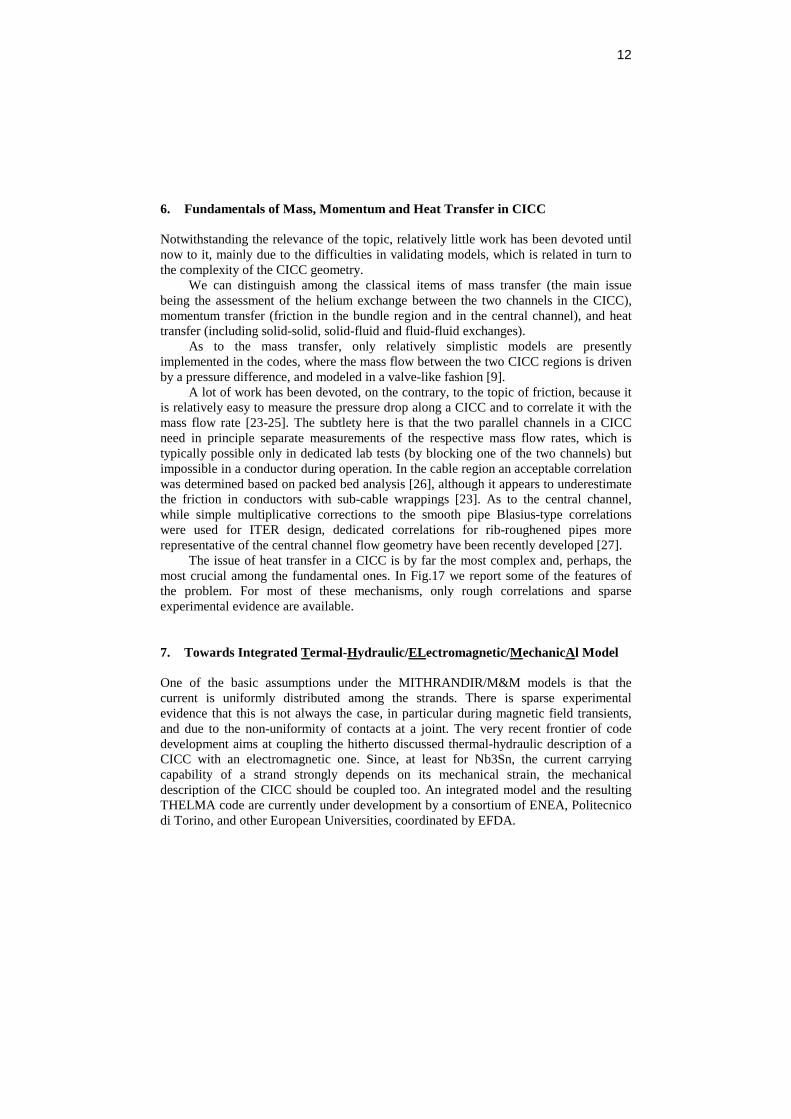
6. Fundamentals of Mass, Momentum and Heat Transfer in CICC Notwithstanding the relevance of the topic, relatively little work has been devoted until now to it, mainly due to the difficulties in validating models, which is related in turn to the complexity of the CICC geometry.
We can distinguish among the classical items of mass transfer (the main issue being the assessment of the helium exchange between the two channels in the CICC), momentum transfer (friction in the bundle region and in the central channel), and heat transfer (including solid-solid, solid-fluid and fluid-fluid exchanges).
As to the mass transfer, only relatively simplistic models are presently implemented in the codes, where the mass flow between the two CICC regions is driven by a pressure difference, and modeled in a valve-like fashion [9].
A lot of work has been devoted, on the contrary, to the topic of friction, because it is relatively easy to measure the pressure drop along a CICC and to correlate it with the mass flow rate [23-25]. The subtlety here is that the two parallel channels in a CICC need in principle separate measurements of the respective mass flow rates, which is typically possible only in dedicated lab tests (by blocking one of the two channels) but impossible in a conductor during operation. In the cable region an acceptable correlation was determined based on packed bed analysis [26], although it appears to underestimate the friction in conductors with sub-cable wrappings [23]. As to the central channel, while simple multiplicative corrections to the smooth pipe Blasius-type correlations were used for ITER design, dedicated correlations for rib-roughened pipes more representative of the central channel flow geometry have been recently developed [27].
The issue of heat transfer in a CICC is by far the most complex and, perhaps, the most crucial among the fundamental ones. In Fig.17 we report some of the features of the problem. For most of these mechanisms, only rough correlations and sparse experimental evidence are available. 7. Towards Integrated Termal-Hydraulic/ELectromagnetic/MechanicAl Model One of the basic assumptions under the MITHRANDIR/M&M models is that the current is uniformly distributed among the strands. There is sparse experimental evidence that this is not always the case, in particular during magnetic field transients, and due to the non-uniformity of contacts at a joint. The very recent frontier of code development aims at coupling the hitherto discussed thermal-hydraulic description of a CICC with an electromagnetic one. Since, at least for Nb3Sn, the current carrying capability of a strand strongly depends on its mechanical strain, the mechanical description of the CICC should be coupled too. An integrated model and the resulting THELMA code are currently under development by a consortium of ENEA, Politecnico di Torino, and other European Universities, coordinated by EFDA.

13
8. Conclusions A strong worldwide R&D program has been realized during the last 10 years or so in the field of superconducting magnets for ITER, and the issue of their refrigeration at liquid helium temperatures appears to be a central one, in particular for transient (accidental) conditions. The development of computational tools has followed on a parallel track and a systematic action has been devoted to their validation in complex realistic situations such as those encountered during the tests of the Model Coils. Although the refrigeration technology appears to perform reasonably well, and presently existing codes, e.g., M&M, have been shown to have good capabilities of reproducing the actual coil behavior in many instances, a number of problems remain open, which will be the subject of research in the years to come.
Figure 17. Different heat transfer mechanisms in a CICC: helium-jacket (upper left), strand-jacket (lower left), helium-strands (upper right), and helium-helium (lower right).
9. Acknowledgments The European Fusion Development Agreement (EFDA) provides financial support for the work in this field at Politecnico di Torino. LSR was also supported by fellowships from ASP and SCENET. We wish to thank all colleagues from laboratories around the world for providing such a stimulating and collaborative environment for our common enterprise of making nuclear fusion a reality. Comments on this manuscript from N.Martovetsky are also gratefully acknowledged.

14
10. References 1. Wilson, M.N. (1983) Superconducting Magnets, Clarendon Press, Oxford. 2. Van Sciver, S.W. (1986) Helium Cryogenics, Plenum Press, New York. 3. Anghel, A., et al. (1997) The Quench Experiment on Long Length (QUELL),
Final Report. 4. Tsuji, H., et al. (2001) Progress of the ITER Central Solenoid Model Coil
Program, Nucl. Fusion 41, 645-651. 5. Martovetsky, N., et al. (2002) Test of ITER Central Solenoid Model Coil and
CS Insert”, IEEE Trans. Appl. Supercond. 12, 600-605. 6. Mitchell, N., and Salpietro, E. (2001) ITER R&D: Magnets: Toroidal Field
Model Coil, Fusion Engineering and Design 55, 171-190; Salpietro, E. (2002) A Toroidal Field Model Coil for the ITER-FEAT project, IEEE Trans. Appl. Supercond. 12 (2002) 623-628; Komarek, P., and Salpietro, E. (1998) The test facility for the ITER TF model coil, Fusion Engineering and Design 41, 213-221.
7. Martovetsky, N., et al. (2002) Test of the ITER TF Insert and Central Solenoid Model Coil, presented at the Applied Superconductivity Conference, August 4-9, Houston, TX, USA.
8. Okuno, K., et al. (2002) Test of the NbAl Insert and ITER Central Solenoid Model Coil, presented at the Applied Superconductivity Conference, August 4-9, Houston, TX, USA.
9. Zanino, R., et al. (1995) A Two-Fluid Code for the Thermohydraulic Transient Analysis of CICC Superconducting Magnets, J. Fus. Energy 14, 25-40.
10. Zanino, R., et al. (1998) Mithrandir+: a Two-Channel Model for Thermal-Hydraulic Analysis of Cable-in-Conduit Super-Conductors cooled with Helium I or II, Cryogenics 38, 525-531.
11. Zanino, R., and Marinucci, C. (1999) Heat Slug Propagation in QUELL. Part I: Experimental Setup and 1-Fluid GANDALF Analysis", Cryogenics 39, 585-593; Heat Slug Propagation in QUELL. Part II: 2-Fluid MITHRANDIR Analysis, Cryogenics 39, 595-608.
12. Zanino, R., et al. (1998) Computer Simulation of Quench Propagation in QUELL, Adv. Cryo. Eng. 43, 181-188.
13. Savoldi, L., et al. (2002) Inductively driven transients in the CS Insert Coil (II): quench tests and analysis, Adv. Cryo. Eng. 47, 423-430.
14. Savoldi Richard, L., et al. (2002) Tests and Analysis of Quench Propagation in the ITER Toroidal Field Conductor Insert, IEEE Trans. Appl. Supercond., to appear.
15. Savoldi, L., et al. (2000) Simulation of Thermal-Hydraulic Transients in Two-Channel CICC with Self-Consistent Boundary Conditions, Adv. Cryo. Eng. 45, 697-704.
16. Zanino, R., et al., (2000) Joint + conductor thermal-hydraulic experiment and analysis on the Full Size Joint Sample using MITHRANDIR 2.1, IEEE Trans. Appl. Supercond. 10, 1110-1113; Savoldi, L., et al. (2000) Tests and Simulation of Thermal-Hydraulic Transients in the US Prototype Joint Sample, Int. J. Mod. Phys. B 14, 3183-3188.

15
17. Savoldi, L., and Zanino, R. (2000) M&M: Multi-Conductor Mithrandir Code for the Simulation of Thermal-Hydraulic Transients in Superconducting Magnets, Cryogenics 40, 179-189.
18. Savoldi, L., and Zanino, R. (2000) Predictive Study of Current Sharing Temperature Test in the Toroidal Field Model Coil without LCT Coil using the M&M Code, Cryogenics 40, 539-548.
19. Savoldi, L., and Zanino, R. (2000) Analysis of TCS Measurement in Conductor 1A of the ITER Central Solenoid Model Coil using the M&M Code, Cryogenics 40, 593-604.
20. Savoldi, L., et al. (2002) First measurement of the current sharing temperature at 80 kA in the ITER Toroidal Field Model Coil (TFMC)”, IEEE Trans. Appl. Supercond. 12, 635-638.
21. Zanino, R., et al. (2002) Analysis and Interpretation of the Full Set (2000-2002) of Tcs Tests in Conductor 1A of the ITER Central Solenoid Model Coil, Cryogenics, submitted for publication.
22. Zanino, R., et al. (2002) Performance evaluation of the ITER Toroidal Field Model Coil Phase I. Part 1 and Part 2, Cryogenics, submitted for publication.
23. Zanino, R., et al. (2002) Pressure drop analysis in the CS Insert Coil, Adv. Cryo. Eng. 47, 364-371.
24. Hamada, K., et al. (2002) Experimental results of pressure drop measurements in ITER CS Model Coil tests, Adv. Cryo. Eng. 47, 407-414.
25. Nicollet, S., et al. (2002) Hydraulic resistance of the ITER Toroidal Field Model Coil dual channel cable-in-conduit conductor pancakes, presented at ICEC19, 22-26 July, Grenoble, France.
26. Katheder, H., (1994) Optimum thermohydraulic operation regime for cable-in-conduit superconductors CICS, Proceedings of ICEC15, 595-598.
27. Zanino, R., et al. (2000), Friction factor correlation with application to the central cooling channel of cable-in-conduit super-conductors for fusion magnets, IEEE Trans. Appl. Supercond. 10, 1066-1069.