Embed Size (px)
Citation preview

4. CONCEPTUAL DESIGN OF
SUPERCONDUCTING MAGNET COILS
Thomas Kupiszewski Owen R. Christianson

Contents
4.1. INTRODUCTION . . . . . . . . . . . . . . . . . . . . . . . . . . . . . . . 4-1
4.2. DESIGN OF MAGNET INTERNALS . . . . . . . . . . . . . . . . . . . . 4-3
4.2.1. Description . . . . . . . . . . . . . . . . . . . . . . . . . . . . . . 4-3
4.2.2. Rationale . . . . . . . . . . . . . . . . . . . . . . . . . . . . . . . 4-12
4.2.3. Cooling Design Options for Insert Coil . . . . . . . . . . . . . . . 4-15
4.3. DESIGN ANALYSIS . . . . . . . . . . . . . . . . . . . . . . . . . . . . . . 4-16
4.3.1. Coil Grading . . . . . . . . . . . . . . . . . . . . . . . . . . . . . 4-16
4.3.2. Thermal Hydraulic Performance . . . . . . . . . . . . . . . . . . . 4-24
4.3.3. Conductor Stability . . . . . . . . . . . . . . . . . . . . . . . . . . 4-27
4.3.4. Quench Performance . . . . . . . . . . . . . . . . . . . . . . . . . 4-34
4.4. SUMMARY AND CONCLUSIONS . . . . . . . . . . . . . . . . . . . . . . 4-46
REFERENCES . . . . . . . . . . . . . . . . . . . . . . . . . . . . . . . . . . . . . 4-50
4. CONCEPTUAL DESIGN OF
SUPERCONDUCTING MAGNET COILS
4.1. INTRODUCTION
Stellarators are steady-state magnetic confinement fusion devices. Unlike tokamaks,
which utilize a combination of ac and dc magnetic fields, stellarators use only dc magnets
since poloidal-field modulation is not required during plasma start-up or for position
control. From a magnet design perspective, the advantages inherent to the stellarator
are the suitability of conventional voltage comparison techniques for quench detection
and device operation without superconductor ac losses.
In this work, a conceptual magnet internal design is developed to meet the operating
requirements representative of stellarator power plants. These requirements, established
by the Stellarator Power Plant Study (SPPS) for the modular Helias-like heliac (MHH),
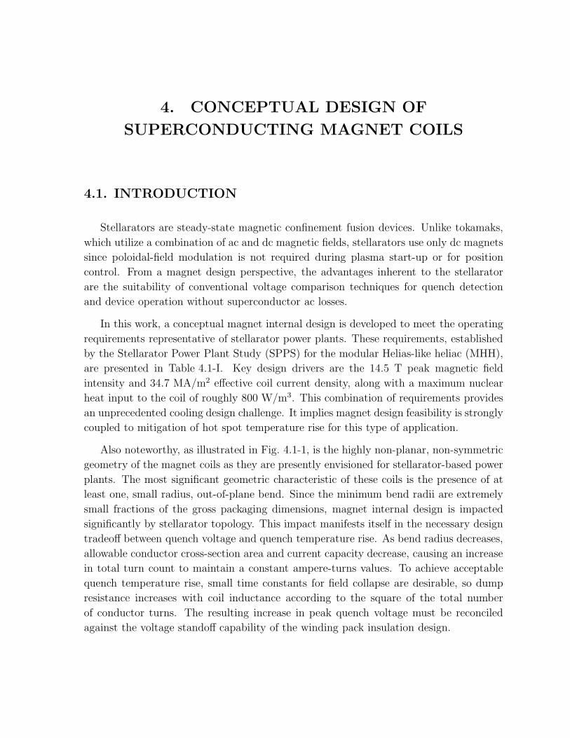
are presented in Table 4.1-I. Key design drivers are the 14.5 T peak magnetic field
intensity and 34.7 MA/m2 effective coil current density, along with a maximum nuclear
heat input to the coil of roughly 800 W/m3. This combination of requirements provides
an unprecedented cooling design challenge. It implies magnet design feasibility is strongly
coupled to mitigation of hot spot temperature rise for this type of application.
Also noteworthy, as illustrated in Fig. 4.1-1, is the highly non-planar, non-symmetric
geometry of the magnet coils as they are presently envisioned for stellarator-based power
plants. The most significant geometric characteristic of these coils is the presence of at
least one, small radius, out-of-plane bend. Since the minimum bend radii are extremely
small fractions of the gross packaging dimensions, magnet internal design is impacted
significantly by stellarator topology. This impact manifests itself in the necessary design
tradeoff between quench voltage and quench temperature rise. As bend radius decreases,
allowable conductor cross-section area and current capacity decrease, causing an increase
in total turn count to maintain a constant ampere-turns values. To achieve acceptable
quench temperature rise, small time constants for field collapse are desirable, so dump
resistance increases with coil inductance according to the square of the total number
of conductor turns. The resulting increase in peak quench voltage must be reconciled
against the voltage standoff capability of the winding pack insulation design.

4-2 CONCEPTUAL DESIGN OF SUPERCONDUCTING MAGNET COILS
Table 4.1-I.
SPPS Magnet Design Requirements
Number of magnets 32
Average coil radius 4.0
Radial coil height (m) 0.78
Lateral coil width (m) 0.51
Minimum coil curvature radius (m) 0.34
Minimum distance between coils (m) 0.12
Plasma average major radius (m) 14.0
Total coil current (MA) 13.8
Total inductance (one-turn) (µH) 816
Stored magnetic energy (GJ) 78
Max magnetic field at coil (T) 14.5
Magnetic field at plasma axis (T) 5.0
Peak coil nuclear heat load (W/cm3) 807
Figure 4.1-1. Elevation view of an 8 magnet quadrant as viewed from the central axis.

4.2. DESIGN OF MAGNET INTERNALS 4-3
The coil concept development philosophy underlying this study was to extrapolate
and adapt the superconductor designs for the International Thermonuclear Experimental
Reactor (ITER) and Toroidal Plasma experiment (TPX) to the performance regime
defined by the stellarator power plant magnet requirements. This philosophy assumed a
design baseline consisting of an Incoloy-908-jacketed Nb3Sn cable-in-conduit conductor
(CICC), with forced convection heat removal using sub-cooled supercritical helium, and
a wind/react/vacuum-pressure-impregnation (VPI) coil manufacturing sequence. From
this baseline, a conceptual point design for the SPPS magnet winding pack was postulated
and a theoretically-feasible preliminary design implementation was developed.
Section 4.2 summarizes the design effort applied to the SPPS magnet internal ar-
rangement and presents a description of the present embodiment of the winding pack
design concept as it has evolved to date. Section 4.3 presents the results of design anal-
yses which support concept feasibility. The scope of these analyses was limited to coil
grading, steady-state thermal-hydraulic simulation, quench performance, and conductor
operating margins.
4.2. DESIGN OF MAGNET INTERNALS
4.2.1. Description
The proposed magnet architecture is based upon a graded winding configuration, as
depicted in Fig. 4.2-1. Grading is achieved in this context by partitioning the winding
window into two regions such that a different ampere-turn coil resides within each re-
gion. This partitioning consist of a low ampere-turn inner coil (aka insert) nested within
a high ampere-turn outer coil (aka outsert). They are energized by separate power
supplies injecting different amounts of electrical current. A theoretically-feasible design
implementation of this graded winding concept is depicted by the dimensioned layout
illustration shown in Fig. 4.2-2. The following discussion refers to this figure.
The outsert portion of the winding pack is further subdivided into two coils, desig-
nated as outsert coils A and B. Both outer coils are layer-wound with 144 turns in 8
nested layers (i.e., 18 turns per layer) for a total current of 6.55 MA per coil, or 45.5 kA
per turn. Each outsert coil is center-tapped and slaved to its own dedicated resistive
dump circuit and charging power supply. Internal heating resulting from neutron attenu-
ation is dissipated convectively by ventilation of the conductors with supercritical helium
flowing at a rate of 3.5 g/s per layer at inlet temperature and pressure conditions of 3 K
and 1.25 MPa, respectively.

4-4 CONCEPTUAL DESIGN OF SUPERCONDUCTING MAGNET COILS
Figure 4.2-1. Comparison of uniform current density and graded coil concepts.
The insert portion of the winding pack is also layer-wound for a total turn count of
240 turns. With a 10 layer radial build, the number of turns per layer is 24. Like the
outsert coils, the insert coil is also forced-flow cooled with supercritical helium. However,
key differences exist. First, because of a smaller minimum bend radius, this coil uses a
smaller conductor. Second, the close proximity of the insert to the plasma implies higher
mass flow rates are needed to remove greater energy deposition by neutrons penetrating
beyond the radiation shields. Results of thermal-hydraulic simulations suggest peak
helium mass flow rates as great as 8 g/s per layer at inlet conditions of 1.25 MPa and
3 K are needed to achieve temperature margins greater than 0.5 K. A third difference is
that the insert coil includes a square auxiliary coolant conduit with a 13 mm diameter
circular channel. This channel is located between the first and second layers of CICC
and rasters in the same direction as the first CICC layer. It is flushed with supercritical
helium at a flow rate of 0.1 kg/s at inlet conditions of 3 K and 1.25 MPa. It augments
heat removal from conductor layers 1 and 3 by conduction across turn insulation barriers
to the auxiliary coolant stream.

4.2. DESIGN OF MAGNET INTERNALS 4-5
Figure 4.2-2. Design implementation of graded coil concept.

4-6 CONCEPTUAL DESIGN OF SUPERCONDUCTING MAGNET COILS
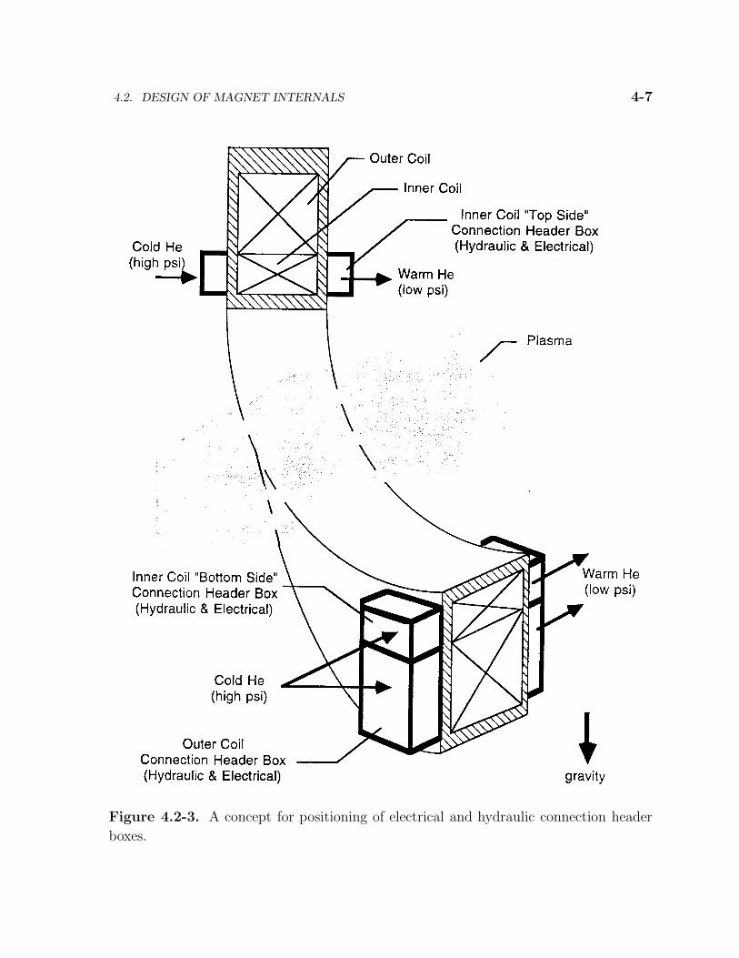
Both the insert coil conductors and auxiliary coolant conduit are wound “two in-hand”
so that temperature rise and pressure drops can be maintained within tolerable limits.
Here, the “two-in-hand” winding technique means that, within any given 24 turn coil
layer, 2 sets of 12 continuous turns of conductor are connected electrically in series, but
hydraulically in parallel. A design ramification is complex electrical joint and hydraulic
plumbing layouts within highly confined clearance spaces between adjacent magnets. A
design solution is illustrated in Fig. 4.2-3. It entails staggering the winding pack entry
and exit points of the conductors by one half of a turn. Accordingly, two pairs of header
boxes would be mounted at the “sides” of the insert coil and would contain helium inlet
and outlet manifolds as well as layer-to- layer electrical joints as needed. This approach
reduces the number of components within a given insert coil header box by 50%. Since
the outer coil does not require “two in-hand” winding, it is equipped with one pair of
header boxes. Because header boxes compete for in-vessel space with other fusion core
equipment, like beam ducts and instrumentation feedthroughs, their actual placement is
a system integration issue.
The two notional conductor designs are presented in Fig. 4.2-4. As envisioned, all
coils would employ Nb3Sn CICC. Both CICC designs use chrome-plated wires, to prevent
sintering during the reaction process, and Incoloy 908 conduits. Selection of Incoloy 908
as the conduit material increases manufacturing cost, but mitigates against degradation
of critical current density due to differential thermal contraction strain during cool-down.
The insert coil CICC is a reduced scale, modified version of the ITER model coil
conductor. It consists of a square 16 mm conduit drawn down around an annular cable
of superconducting wires tightly compacted around a 7 mm OD × 5 mm ID coil spring
running the entire length of conductor. This central channel provides a low impedance
path for the helium mass flows required to dissipate nuclear heat. Without this central
channel, supercritical helium moving through the cable void space would eventually enter
the subcritical state and unreliable conductor performance would probably occur as a
consequence of two phase flow. A triplex-based, 3 or 4 stage cabling process could be
used to spiral 6 to 8 subcables around the central channel. With a cable space void
fraction of 0.3, wire diameter would be comparable to the Westinghouse LCT wire [1],
ranging from 0.62 mm to 0.7 mm. However, Nb3Sn processing yields would have to be
greater than those for LCT since a Cu to non-Cu ratio of 1:1 would be needed to achieve
margin. The ratio of minimum bend radius to conductor dimension is 340/16 ' 21.3.
The outsert coils CICC is a larger version of the Westinghouse LCT conductor. It
consists of a square 25.7 mm conduit, or jacket, drawn down around a 5 stage cable
of 486 superconducting wires. With a cable space void fraction of 0.35 and conduit
4.2. DESIGN OF MAGNET INTERNALS 4-7
Figure 4.2-3. A concept for positioning of electrical and hydraulic connection header
boxes.

4-8 CONCEPTUAL DESIGN OF SUPERCONDUCTING MAGNET COILS
Figure 4.2-4. Notional conductor design configurations.

4.2. DESIGN OF MAGNET INTERNALS 4-9
wall thickness of 2 mm, wire diameter would equal approximately 0.9 mm, roughly 32%
greater than the LCT wire. No central channel is needed since adequate mass flow rates
can be developed without decreasing pressure below the critical value near 0.23 MPa.
The ratio of minimum bend radius to conductor dimension is 609/25.7 ' 23.7.
Both conductors would be wrapped with turn insulation possessing a nominal com-
pressed build of 1.25 mm (i.e., four, 0.012” half-lapped tapes). If the coils were fabricated
using present technology and techniques, turn and ground wall insulation would probably
default to fiberglass or ceramic fabric tapes. This approach presents a tractable level of
risk for the insert coil since predicted quench voltages are less than 1 kV. To assure re-
liable operation of the outsert coils, void-free vacuum pressure impregnation (VPI) with
epoxy and a center-tapped winding would be absolute necessities since the predicted
quench voltage drop to ground is 15 kV for a non center-tapped configuration (30 kV if
both outserts are consolidated into a single non center-tapped coil). If coils are inserted
within support cases after reaction of the conductor, then application of polyimide film
sheets as a ground wall barrier becomes an option. Our key operating assumption has
been that a cost-effective, reliable insulate-wind-react-VPI manufacturing sequence is
available if coil fabrication were to begin at some future time, perhaps as much as twenty
years hence.
A candidate case structure design concept is illustrated in Figs. 4.2-5 and 4.2-6.
Figure 4.2-5 depicts the magnet case without coils. Figure 4.2-6 depicts the coils inserted
within the case. The case is constructed from four circumferential bands and three pairs
of side wall plate assemblies. The circumferential bands also function as mandrels for coil
winding, so they are referred to as mandrel bands. All case material is 316LN stainless
steel or, alternatively, Incoloy 908. The insert coil mandrel band is overwrapped with
a 24 turn coil of conductor conduit (w/o cable) on its outermost surface. Supercritical
helium flows in this conduit, intercepting nuclear heat within the band before it conducts
to the first conductor layer. Usage of CICC conduit as a coolant tube negates the need for
extensive machining or welding operations performed on the mandrel band to interface
cooling hardware. A similar arrangement exists between the insert coil and the adjacent
outsert coil. Accompanying flange surfaces for all mandrel bands are provided by side wall
plates joined to the bands. As presently envisioned, this joining is accomplished by full
plug welds located at through-running holes in the side wall plates. The proposed usage
of plug welds is intended as a potential means of eliminating or greatly reducing plate
distortion due to weld shrinkage. Since the primary load transfer path passes through
these plug welds, their number and size must be chosen to provide sufficient section area
such that weld zone stresses do not reach yield values. These plug welds are supplemented
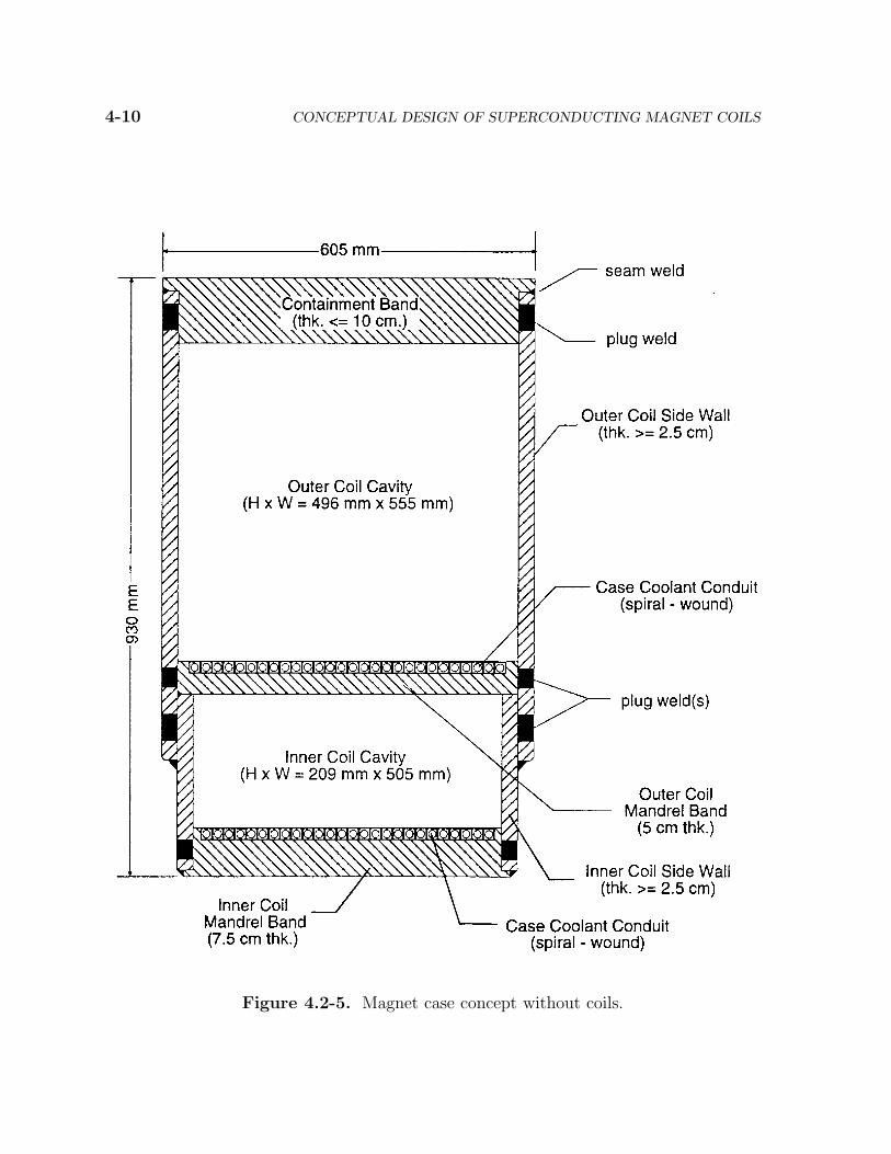
4-10 CONCEPTUAL DESIGN OF SUPERCONDUCTING MAGNET COILS
Figure 4.2-5. Magnet case concept without coils.

4.2. DESIGN OF MAGNET INTERNALS 4-11
Figure 4.2-6. Cross-section view of magnet case and coils.

4-12 CONCEPTUAL DESIGN OF SUPERCONDUCTING MAGNET COILS
with continuous fillet “seam” welds which traverse the case circumferentially, parallel
to the direction of current flow. Although the seam welds improve case rigidity and
overall load-bearing strength, their primary function is to seal the case for VPI during
manufacture and to contain conductor coolant in the event of conduit leakage. Closing
the case is a 7.5 cm thick outer belt which contains the outsert coil. Again, plug and
seam welds would be used for joining.
In general, considerable care must be taken during welding to prevent thermal dam-
age. For mitigating against thermal damage to the winding pack, each mandrel to flange
plate interface surface undergoes a right angle bend to reduce exposure of the ground wall
insulation material to weld flash. In addition, although not depicted in either Fig. 4.2-5
or Fig. 4.2-6, the use of integral, water-cooled, chill blocks is envisioned to shield the
winding pack from weld-related heat effects. These chill blocks would be located within
shallow channels milled into the interior-facing sides of all mandrel and side wall plates.
4.2.2. Rationale
4.2.2.1. Cooling Design
To produce magnetic fields in the >14 T regime, recent magnet development efforts
have relied upon coil operation at 1.8 K for achieving adequate superconductor temper-
ature margin. At the National High Magnetic Field Laboratory (NHMFL), for exam-
ple, the design of the 14-T, NB3Sn, CICC outsert [2] of a 45-T hybrid magnet system
was based on static HeII cooling. And in Japan, a pool-boiled, fully-superconducting,
(Nb,Ti)3Sn magnet system [3] successfully achieved 20 T while operating in a bath of
saturated HeII.
Although both of the aforementioned cooling design approaches are suitable for labo-
ratory applications, they are not readily scalable to power-plant operating environments.
Consider, for example, a hypothetical CICC coil stabilized by static HeII cooling at 1.8 K
with a peak nuclear heat input of roughly 1000 W/m3 per unit length of cable. With
a maximum critical channel heat flow limit [4] of 7.4 W/cm5/3 for HeII at atmospheric
pressure, the spacing of 1.8 K coolant ports along the conduit wall could not exceed 16 m
without causing fluid temperature to exceed the lambda transition value at the halfway
point between the ports. Alternatively, if magnets are HeII bath-cooled, winding packs
must be provided with a multiplicity of internal coolant channels to dissipate the nuclear
heat load adequately and maintain near isothermal conditions. These channels increase
structural compliance of the winding packs, thereby increasing the difficulty of reliable
4.2. DESIGN OF MAGNET INTERNALS 4-13
load transfer between adjacent magnets. Bath-cooling of non-planar stellarator coils also
presents the nontrivial challenge of preventing vapor lock along horizontal portions of
the coolant channels. To prevent bubble formation, these channels must be sized also
according to the critical channel heat flow limit. Consequently, effective current density
would tend to decrease.
Based on the aforementioned considerations, forced-flow cooling with supercritical
helium was selected as the preferred option for the design baseline. Subcooling the helium
to 3 K was motivated by results of conductor operating margin analysis, as documented
in Section 3.3. Since the flow path lengths are very long (approximately 25 m per turn
on average), helium inlet pressure was set to 1.25 MPa to provide sufficient pressure head
for sustaining single phase flow at the flow rates required for removing large nuclear heat
loads. Furthermore, these inlet conditions are approximately equivalent to those of the
Westinghouse LCT coil [1], so they are therefore not a far extrapolation from known
refrigerator design space. Selection of the CICC approach to forced-flow cooling also
provides the benefits of a distributed winding support and coolant vessel structure as
well as minimum quench energies greater than 150 mJ/cm3 of strand material [5].
Three winding options were considered from the perspective of cooling design. These
options were single-pancake winding, double-pancake winding, and layer winding. Layer
winding was chosen for two reasons. First, in comparison to double-pancake CICC coils,
layer-wound CICC coils do not suffer from the significant increase [6] in hot spot tem-
perature, near the midpoint of the flow path, beyond that which would occur if the turns
were adiabatically isolated from one another. In layer wound geometries, coolant tem-
perature increases monotonically along the flow path, attaining the hot spot value at
the outlet. Second, due to the aspect ratio of the nominally-rectangular cross-section of
the winding window, layer winding translates to shorter flow paths than those associated
with double-pancake or even single-pancake winding. Hence, pumping power and quench
pressure rise are reduced.
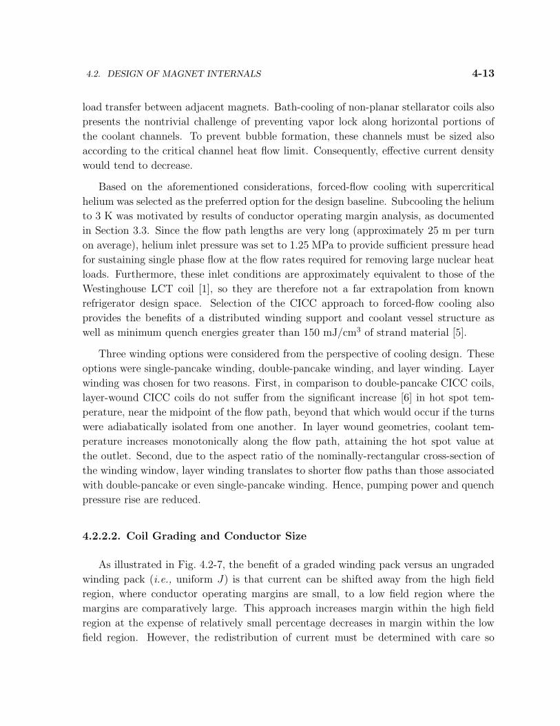
4.2.2.2. Coil Grading and Conductor Size
As illustrated in Fig. 4.2-7, the benefit of a graded winding pack versus an ungraded
winding pack (i.e., uniform J) is that current can be shifted away from the high field
region, where conductor operating margins are small, to a low field region where the
margins are comparatively large. This approach increases margin within the high field
region at the expense of relatively small percentage decreases in margin within the low
field region. However, the redistribution of current must be determined with care so
4-14 CONCEPTUAL DESIGN OF SUPERCONDUCTING MAGNET COILS
Figure 4.2-7. Benefit of graded winding pack vs a uniform current density configuration.
magnetic field at the plasma axis is maintained at roughly 5 T. Magnetic field calculations
were undertaken to determine that the change in plasma axis field attributable to the
chosen grading scheme would not exceed 5% of the nominal value. Results of these
analyses are presented in Sec. 4.3.1 and suggest the plasma field impact of the chosen
grading scheme is limited to about 3%. The effect on field quality (i.e., harmonics),
however, was not assessed.
The most significant coil geometric characteristic is the presence of at least one, small
radius, out-of-plane bend. Since the coils minimum bend radii are extremely small frac-
tions of the gross packaging dimensions, magnet internal design is impacted significantly
by stellarator topology. This impact manifests itself in the necessary design tradeoff be-
tween quench voltage and quench temperature rise. As bend radius decreases, allowable

4.2. DESIGN OF MAGNET INTERNALS 4-15
CICC cross-section area and current capacity must decrease, causing an increase in total
turn count to maintain a constant ampere-turns value. To achieve acceptable quench
temperature rise, small time constants for field collapse are desirable, so dump resistance
increases with coil inductance according to the square of the total number of conductor
turns. The resulting increase in peak quench voltage must be reconciled against the
voltage standoff capability of the winding pack insulation design. In general, fewer turns
(i.e., larger CICC dimensions) translates to lower quench voltage, hence less dielectric
stress on the insulation design.
Based on results of ITER model coil CICC bending tests [7], the bend radius limit is
estimated to be no less than 20 times the conduit external dimension. This criterion was
applied to size both insert and outsert coil CICC conduits. The larger bend radius of the
outsert coils allowed a larger CICC, hence a reduction in self-inductance. However, this
reduction was not sufficient for achieving quench voltages less than 20 kV to ground. To
limit outsert coil quench voltage to less than 20 kV while simultaneously limiting quench
temperature to less than 300 K, the outsert coil was subdivided such that each outsert
“subcoil” would possess the same number of turns and would, in the event of a detected
quench, discharge into a separate dump resistor. Results of quench performance analyses
presented in Section 3.4 suggest this coil partitioning scheme reduces quench temperature
to roughly 150 K at a quench voltage of 15 kV, or ±7.5 kV if each outsert winding is
center-tapped. Such quench performance was judged as providing a reasonable balance
between design conservatism, system complexity, and technical risk.
4.2.3. Cooling Design Options for Insert Coil
At present, the predicted minimum temperature margin of the insert coil is 0.7 K.
Three cooling design options have been identified for increasing this minimum tempera-
ture margin. These options are:
1. Change present routing of helium through “two-in-hand” wound layers from parallel
flow to counterflow.
2. Remove electrical insulation wrap surrounding each turn of the auxiliary coolant
conduit layer, thereby reducing the transverse heat conduction impedance between
the first three coil layers by nearly 50%.
3. Add a second layer of auxiliary coolant conduit. This can be done by replacing
the existing auxiliary coolant conduit layer with a CICC layer and replacing the

4-16 CONCEPTUAL DESIGN OF SUPERCONDUCTING MAGNET COILS
resulting first and third CICC layers with auxiliary coolant conduit. (Here, the
tradeoff centers around doubling the local heat removal capacity to reduce hot spot
temperature versus slightly decreasing temperature margin as conductor current
increases by 12.5%).
Analysis of these design optimization measures was beyond the scope of the present
feasibility study. However, the availability of various approaches to increasing design
conservatism is another favorable indicator of overall magnet design feasibility.
4.3. DESIGN ANALYSIS
4.3.1. Coil Grading
Four alternative schemes for coil (i.e., current) grading were considered. These alter-
native schemes are illustrated in Fig. 4.3-1. Scheme 1 employs three coils in an attempt
to reduce manufacturing cost by utilizing NbTi superconductor in 30% of the current
window. The other schemes all employ two coils. Schemes 2 and 3 are geometrically
identical, but operating temperature and superconductor differ. Scheme 2 operates with
superfluid helium, allowing the large outer coil to be wound with the less expensive
NbTi conductor. Scheme 3 operates at subcooled supercritical helium temperatures and
would utilize all Nb3Sn superconductor. Scheme 4 is essentially a geometric variation
of Scheme 3. Also shown on Fig. 4.3-1 are estimated values and locations for magnetic
field intensity at the coil boundaries. These estimates were made by visual inspection
of magnetic field plots provided [8] to Westinghouse. It is important to note that it was
assumed for expediency that the fields at the coil do not change significantly by grading.
This simplifying assumption is clearly not correct in a rigorous sense, but it uncouples the
problem, allowing the conductor temperature margin calculations to proceed for purposes
of down-selecting a preferred scheme.
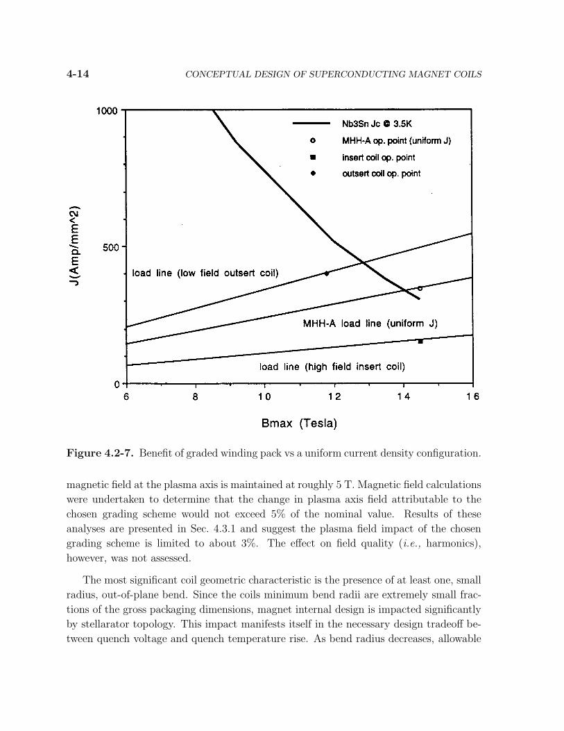
Magnetic Field Code (MAFCO) was used to develop two simple Biot-Savart electro-
magnetic models for evaluating these schemes (Figs. 4.3-2 and 4.3-3). The first model,
presented in Fig. 4.3-2, is a circular toroid consisting of a total of 32 solenoid coils whose
centers are coplanar and located at 14 m from the global origin. These coils have the
same 4 m average radius as the stellarator coils. The coil centers are spaced at equal
angular increments around a 28 m diameter circular path. The coils are oriented so that
their mid-planes all intersect at a vertical line running through the global origin. The

4.3
.D
ESIG
NA
NA
LY
SIS
4-1
7
Figure 4.3-1. Candidate schemes for coil grading.
4-18 CONCEPTUAL DESIGN OF SUPERCONDUCTING MAGNET COILS
Figure 4.3-2. Plan and elevation views of circular toroid model used to predict relative
changes in plasma magnetic field due to coil grading.

4.3. DESIGN ANALYSIS 4-19
Figure 4.3-3. Plan and elevation views of 4-lobed toroid model used to predict relative
changes in plasma magnetic field due to coil grading.

4-20 CONCEPTUAL DESIGN OF SUPERCONDUCTING MAGNET COILS
Figure 4.3-4. Plan view of SPPS magnet array.

4.3. DESIGN ANALYSIS 4-21
second model, presented in Fig. 4.3-3 and called the 4-lobed toroid, is derived from the
first model by co-locating the solenoid coil centers in Cartesian (X, Y, Z) space with the
corresponding centers for the stellarator coils. This refinement was done to simulate the
quadrant layout of the stellarator coil array, which is illustrated for comparison purposes
in the plan view in Fig. 4.3-4. Clearly, both models are gross, first order approximations
to the stellarator magnet array geometry. The intent, however, was not to calculate mag-
netic field with a high degree of accuracy, but to estimate relative changes in magnetic
field due to coil grading.
Graphs of the predicted relative field change versus global radius due to coil grading
are presented for Coil 1 (a coil at the corner of the array) and Coil 4 (a mid-side coil
between corners) in Figures 4.3-5 and 4.3-6, respectively. These results were generated
by the 4-lobed model and have been normalized to a parameter designated as B∗, which
is the field for the uniform current density baseline case. Our results suggest that all
four grading schemes should have negligible impact (< 3%) on the field magnitude at the
plasma axis. This is not surprising, however, since the winding window dimensions are
less than one fourth of the mean coil radius.
The circular toroid model was used also to predict the product of overall current
density times circumferential field in the global Z = 0 plane. This product is the local
Lorentz force density and, on a relative basis, is an indicator of which coil grading scheme
should incur the least mechanical stress. The results for grading schemes 2 (same as 4)
and 3 are plotted versus global radius at the inboard leg in Fig. 4.3-7 and are compared
against those for uniform current density. The relative differences in peak force density
magnitude suggest that grading scheme 4 would be the most benign from a structural
engineering perspective. However, scheme 3 was chosen because it is characterized by the
greatest combined conductor temperature margin for both inner and outer coils. This
margin was calculated according to the methodology discussed in Sec. 4.3.3. The results
for isothermal coil conditions, corresponding to no internal nuclear heating, are presented
in Table 4.3-I. A Nb3Sn wire strain of 0.35% was assumed.

4-22 CONCEPTUAL DESIGN OF SUPERCONDUCTING MAGNET COILS
Figure 4.3-5. Relative changes in coil 1 magnetic field distribution at Z = 0 and
Θ = 4.463 due to alternative coil grading schemes (B∗ is the field with a uniform
current density).
Figure 4.3-6. Relative changes in coil 4 magnetic field distribution at Z = 0 and
Θ = 37.541 due to alternative coil grading schemes (B∗ is the field with a uniform
current density).

4.3. DESIGN ANALYSIS 4-23
Table 4.3-I.
Preliminary Temperature Margin Predictions
for Coil Grading Schemes (No Nuclear Heating)
Temperature Coil A Coil B Coil C
Margin (K) (insert) (outsert) (outsert)
Scheme 1 7.6 4.2 2.25
Scheme 2 9.2 2.6
Scheme 3 7.6 6.4
Scheme 4 6.0 3.9
Figure 4.3-7. Product of current density times theta component of magnetic field versus
radius as predicted by circular toroid model.

4-24 CONCEPTUAL DESIGN OF SUPERCONDUCTING MAGNET COILS
4.3.2. Thermal Hydraulic Performance
The steady-state thermal hydraulic performance of the stellarator coils determines
hot spot temperature rise due to nuclear heating. This hot spot temperature value has
the effect of translating the superconducting critical surface towards the design operating
point along the magnet load line since peak magnetic fields and peak nuclear heating rates
are co-located within the same region of the stellarator coil. Consequently, coil design
feasibility is strongly dependent upon the extent of temperature rise.
To model the fluid mechanics of supercritical helium, the Navier-Stokes equations
including the effects of finite compressibility are used. Helium pressure and temperature
profiles along the CICC flow path are obtained from integrating the following nonlinear
differential equations, derived from an enthalpy balance [9] on a control volume:
dP
dx=
−2fG2/(ρD) + 4qGβ/[ρD(Cp − u2β)]
1 − (G2/ρ)(κ + Bφ), (4.3-1)
dT
dx=
−2fG2φ/(ρD) + 4q/[GD(Cp − µ2β)]
1 − (G2/ρ)(κ + βφ), (4.3-2)
where the parameter φ is defined as
φ =µjCp + u2κ
Cp − u2β. (4.3-3)
Here, P is pressure, T is temperature, x is position along the flow path mass flow rate, ρ is
density, D is hydraulic diameter, q is the heat input flux, Cp is constant pressure specific
heat, u is the bulk flow velocity, β is bulk expansivity, κ is bulk compressibility, and
µj is Joule-Thomson coefficient. Helium properties were provided by Cryodata HEPAK
software.
For the CICC cable space, relevant friction factors are given by Hooper’s correla-
tion [10] to Lue’s data [11]. The correlation for the friction factor in the central chan-
nel [12] of the insert coil CICC is given by:
f = 0.092 Re0.2D , (4.3-4)
where ReD is the Reynolds number of the central channel. This correlation yields friction
factors roughly twice that of smooth tubes. Consequently, almost all of the helium flow
in the insert coil CICC occurs in the central channel. For these scoping studies, it was
assumed all of the flow can be allocated to the central channel.

4.3. DESIGN ANALYSIS 4-25
The heat input flux, q, along the flow path was determined from the volumetric nuclear
heat generation profile plotted in Fig. 4.3-8 from data supplied [13] to Westinghouse.
This was done by multiplying the volumetric heat generation rate for a given coil layer
by the ratio of CICC cross-section area to wetted perimeter. The effect of turn-to-turn
heat conduction between adjacent coil layers was included via an equivalent thermal
circuit approach based on the conduit insulation turn geometry and an assumed thermal
conductivity comparable to that of G10/11 epoxy-glass composite.
Results for the outsert coil A layer closest to the plasma are presented in Fig. 4.3-9.
The predicted hot spot temperature is 5.2 K and is located at the helium outlet. The
pressure drop is roughly 4 atmospheres at a flow rate of 3.5 g/s. Hot spot temperature
could be reduced by reducing inlet pressure to increase helium specific heat capacity, by
increasing mass flow rate, by subcooling to 2.5 K, or a combination of all three. Fig-
ure 4.3-10 presents the thermal-hydraulic response of the secondary auxiliary case coolant
flow stream. Case coolant exits at nearly 4.7 K, which is less than the aforementioned
5.2 K hot spot temperature, so it clearly is also dissipating some of the heat deposited
in the outsert coil as well as intercepting case heat load. Despite the large flow rate of
100 g/s, the pressure drop is roughly 2.3 atm.
Figure 4.3-8. Distribution of volumetric nuclear heating within magnet.

4-26 CONCEPTUAL DESIGN OF SUPERCONDUCTING MAGNET COILS
Figure 4.3-9. Predicted worst case thermal-hydraulic performance of outsert coil (heat
input is 40 W/m3 and flow rate is 3.5 g/s).
Figure 4.3-10. Predicted helium temperature and pressure profiles in secondary case
cooling conduit (heat input is 32 W/m3 and flow rate is 100 g/s)..

4.3. DESIGN ANALYSIS 4-27
Results for the insert coil layer closest to the plasma are presented in Figs. 4.3-11 and
4.3-12. Figure 4.3-11 indicates the predicted hot spot temperature is 5.7 K. The hot spot
occurs upstream of the outlet due to expansion cooling of the helium (Joule-Thomson
effect). A similar effect is predicted for the third layer (second CICC layer). However,
the auxiliary coolant stream (layer 2) exhibits monotonically increasing temperature.
Figure 4.3-12 presents the pressure profiles for these three layers. The predicted CICC
outlet pressure in the 0.3 MPa to 0.4 MPa range suggests inlet pressures cannot be
greatly reduced while safely maintaining single phase flow everywhere along the flow
path. The great disparity between CICC flow rates and auxiliary coolant conduit (layer
2) flow rates is due to greater friction factors and smaller hydraulic diameters of the
CICC. These results were based on the assumption the primary auxiliary case coolant
flow stream intercepts all of the roughly 1 kW of nuclear heat deposited in the insert coil
mandrel band.
4.3.3. Conductor Stability
The stability of the stellarator conductor is described by how close the operating
point is to the critical surface in terms of distance in (I, B, T ) space. Field margin,
temperature margin, quench point, minimum propagating zone, and minimum quench
energy are useful figures of merit in evaluating design feasibility.
The superconducting critical surface is determined by using temperature and mag-
netic field dependent critical current correlations. Morgan’s correlation [14] and a West-
inghouse correlation [15, 16] similar to Green’s formulation [17] is used for NbTi, and
Summer’s formulation [18] is used for Nb3Sn.
The quench point is the intersection of the load line with the critical surface. The
distance along the load line, LL, is given by:
LL =Iop
Iq=
Bop
Bq. (4.3-5)
The temperature margin, TM , is given by:
TM = Tq − Tcond . (4.3-6)
The field margin, FM , is given by:
FM =Iq − Iop
Iop=
Bq − Bop
Bop, (4.3-7)

4-28 CONCEPTUAL DESIGN OF SUPERCONDUCTING MAGNET COILS
Figure 4.3-11. Predicted worst case conductor temperature profiles in the insert coil
(heat input is 800 W/m3).
Figure 4.3-12. Predicted helium pressure profiles in the insert coil (heat input is
800 W/m3).

4.3. DESIGN ANALYSIS 4-29
where Iq is the quench current, Iop is the operating current, Bop is the magnetic field at the
operating point. It is assumed that the load line is linear (i.e., no materials are present
which exhibit saturation effects). The temperature margin is found by numerically finding
the temperature at which the critical surface intersects a particular point on the load line.
Stability is also described by the minimum propagating zone (MPZ) and the min-
imum quench energy (MQE) [19]. A normal zone larger than the MPZ will grow in
length. A normal zone smaller than the MPZ will recover. In a one dimension adiabatic
approximation, the MPZ is estimated by l,
l =
[
2k(Θc − Θo)
J2c ρ
]1/2
, (4.3-8)
critical temperature, Θo is the bath or operating temperature, Jc is the superconducting
critical current density, and ρ is the resistivity of the strand. The MQE is the energy
necessary to create a normal zone of length equal to the MPZ, i.e.,
MQE =∫
Θc
Θo
l A C(T )dT , (4.3-9)
where A is the conductor area and C is the conductor specific heat. While a one dimen-
sional approximation for MQE is used here for simplicity, a more detailed design effort
should consider two-dimensional geometry that is more appropriate to the stellarator ge-
ometry. The one dimensional approximation is used for simplicity. The one dimensional
approximation is invalid when the MPZ is smaller than the strand diameter. In this case
the strand diameter is used for the MPZ instead of the calculated value.
The effects of cooling and enthalpy of helium are included in the MQE. The dual
stability region separating the well cooled regime from the ill-cooled regime is found
from
ilim =
[
Acu p h (Tc − Tb)
ηIc2
]1/2
, (4.3-10)
where Acu is the copper area, p is the wetted perimeter, h is the heat transfer coefficient,
Tc is the critical temperature, and η is the copper resistivity [20]. The physical constants
used in the MPZ and MQE are Kohler plot for the resistivity of copper [21], Lorentz
ratio is used to determine thermal conductivity, and the computer code Cryodata [22] is
used for the specific heat of the elements comprising the conductor and helium.
The stability is actually described by comparing the MQE to the disturbance spectrum
of the magnet. Prediction of the disturbance spectrum is beyond the scope of this work.

4-30 CONCEPTUAL DESIGN OF SUPERCONDUCTING MAGNET COILS
Typical energy deposition due to ac losses from plasma disruptions in Tokamak machines
will range from 100 to 150 mJ/cm3 of strand materials [23]. A MQE of about 100 mJ/cm3
is assumed to be a minimum value for stability in these large conductors.
4.3.3.1. Insert Coil Operating Point and Margin
The operating point for the insert coil without nuclear heating is 84% along the load
line, shown in Fig. 4.3-13. The temperature margin is 3.4 K at the operating point.
Including nuclear heating results in a temperature rise of 2.7 K with the conductor
operating at 5.7 K. The margin is reduced to 0.7 K, and the conductor operates closer
to the critical surface, 95% along the load line, see Fig. 4.3-14. (In both figures, the unit
for the vertical axis is ampere-turns.)
The MQE is calculated using MPZ theory. Inclusion of the cooling and enthalpy
of the helium in the conduit results in a MQE of about 2,000 mJ/cm3, as shown in
Fig. 4.3-15. The well-cooled regime extends past the operating point. Experimentally,
the LCP conductor had a MQE of about 1.5 to 1.8 J/cm3 [24]. This MQE exceeds the
100 mJ/cm3 design goal.
Figure 4.3-13. The critical surface, load line, operating point, quench point, and
temperature margin for the proposed insert coil conductor without the nuclear heating
temperature rise. (For LL = 84%, Iop/Ic = 43%, TM = 3.4 K, and kf = 0.09.)

4.3. DESIGN ANALYSIS 4-31
Figure 4.3-14. The critical surface, load line, operating point, quench point, and
temperature margin for the proposed insert coil conductor with the nuclear heating tem-
perature rise included. (For LL = 96%, Iop/Ic = 78%, TM = 0.7 K, and kf = 0.09.)
Figure 4.3-15. The minimum quench energy of the insert coil derived from the minimum
propagating zone.

4-32 CONCEPTUAL DESIGN OF SUPERCONDUCTING MAGNET COILS
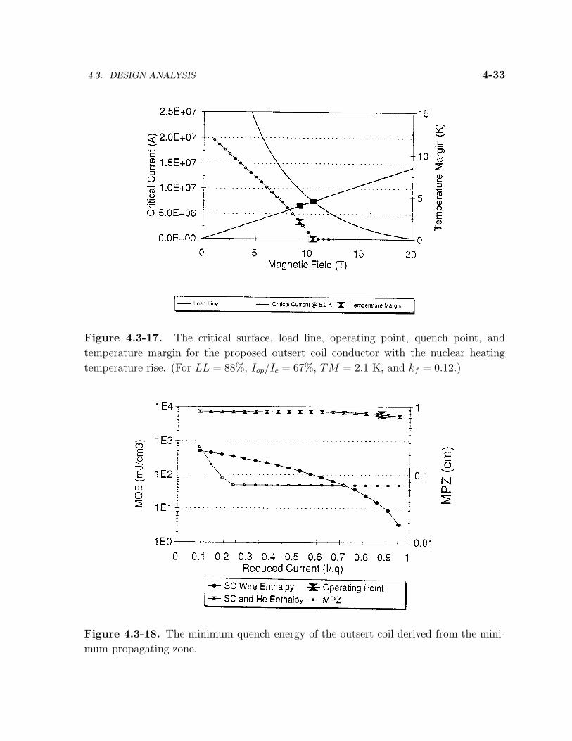
4.3.3.2. Outsert Coil Operating Point and Margin
The operating point for the outer coil without nuclear heating is 80% along the load
line, shown in Fig 4.3-16. The temperature margin is 4.3 K at the operating point.
Including nuclear heating results in a temperature rise of 2.2 K with the conductor
operating at 5.2 K. The margin is reduced to 2.1 K, and the conductor operates closer
to the critical surface, 88% along the load line as is shown in Fig. 4.3-17.
The MQE is calculated using MPZ theory. Inclusion of the cooling and enthalpy of the
helium in the conduit results in a MQE of about 3,000 mJ/cm3, as shown in Fig. 4.3-18.
This MQE exceeds the 100 mJ/cm3 design goal. The well-cooled regime extends well
past the operating point.
Figure 4.3-16. The critical surface, load line, operating point, quench point, and
temperature margin for the proposed outsert conductor without the nuclear heating
temperature rise. (For LL = 80%, Iop/Ic = 53%, TM = 4.3 K, and kf = 0.12.)
4.3. DESIGN ANALYSIS 4-33
Figure 4.3-17. The critical surface, load line, operating point, quench point, and
temperature margin for the proposed outsert coil conductor with the nuclear heating
temperature rise. (For LL = 88%, Iop/Ic = 67%, TM = 2.1 K, and kf = 0.12.)
Figure 4.3-18. The minimum quench energy of the outsert coil derived from the mini-
mum propagating zone.
4-34 CONCEPTUAL DESIGN OF SUPERCONDUCTING MAGNET COILS
4.3.3.3. Discussion of Radiation Effects and Wire Development
The Nb3Sn superconductor critical current is sensitive to strain in the conductor.
Strains over 0.35% result in unrecoverable degradation in the critical current. In addi-
tion, the Nb3Sn filaments will break if the stress in the conductor exceeds about 250 to
300 MPa. Using typical stress-strain values for the materials used in the conductor and
coil pack, the stress for a particular superconductor fill factor can be found at a given
strain. Results are shown in Fig. 4.3-19.
Preliminary estimates of the stress in the conductor indicate values around 250 MPa.
The coil design is in the correct stress-strain and fill factor region for a feasible design.
The critical currents used in the margin and stability sections are typical values in
use today, resulting in a magnet design that will work with today’s superconductors.
Improvements in the critical current are possible, see for example an increase by a fac-
tor of two described by Pourrahimi [23] or Foner [24] for laboratory powder metallurgy
processing. It is also possible a wire development program today with the wire manu-
facturers might allow optimization of the superconductor at the magnetic fields required
for a stellarator.
The radiation environment of the stellarator will be intense with a neutron fluence of
1023 n/m2. Radiation creates defects in the superconducting lattice. For weakly pinned
superconductors typical of bulk superconducting filaments, the radiation defects can
actually add pinning sites and increase the critical current initially (e.g., see Ref. [25]).
Summers estimated the effect of radiation upon the critical current. Calculations for
Nb3Sn superconductor are shown in Fig 4.3-20. Initially the critical current increases, but
then the critical current decreases. This figure suggests that the radiation environment
will not be a problem in the stellarator. However, the change in critical current will be
dependent upon the initial pinning state of the superconductor.
4.3.4. Quench Performance
The quench performance of the cable-in-conduit conductors used in the inner and
outer coils is modeled by two different techniques. One technique calculates the hot spot
temperature in an adiabatic, one dimensional approximation. This simple calculation
is typically called a MIITS calculation. The second technique solves the one dimen-
sional conservation relations for the helium mass and momentum together with energy
conservation relations for the helium, the conductor, and conduit wall.

4.3. DESIGN ANALYSIS 4-35
Figure 4.3-19. Acceptable fill factors for different amounts of stress at a strain of 0.35%.
Figure 4.3-20. Change in critical current in Nb3Sn as a function of neutron fluence.

4-36 CONCEPTUAL DESIGN OF SUPERCONDUCTING MAGNET COILS
4.3.4.1. MIITS Calculation
The quench temperature rise is predicted using an adiabatic, one dimensional approx-
imation of a conductor carrying a current. A simple heat balance is
I2(t) ρ(T )
Acu
dt = A C(T )dT . (4.3-11)
Rearranging and integrating gives [26]
∫ t
oI2dt = Acu A
∫ T
To
C(T )
ρ(T )dT . (4.3-12)
The units are MIITS (106 A2−s). The left hand integral is a function of temperature.
To simplify the problem to save time, it is assumed that the current decay is entirely
controlled by the dump resistor. The current decays with a time constant of L/R where
L is the inductance of a single magnet and R is the resistance of a single dump resistor
which is slaved to a single magnet. The inductance is derived from the total stored
energy and scaled by 1/32 to estimate the self inductance of a single typical magnet.
Mutual inductance between adjacent coils is ignored. The constant L/R current decay
approximation ignores propagating normal zones.
Evaluation of the right hand integral requires values for the physical parameters.
The specific heat copper, iron, and the elements comprising Nb3Sn are obtained from the
computer program Cryodata [22] (Values beyond 300 K are extrapolated). The resistance
of copper as a function of field is derived from a Kohler plot with Fickett’s empirically
derived coefficients [21], and the temperature dependence follows the equation [26]
ρ(T, RRR) = 1.545 × 10⁻⁸RRR−1 +[
2.32547× 10¹⁷T−5 + 9.57137× 10¹³T−3 + 1.62735 × 10¹⁰T]
−1
. (4.3-13)
These quantities are plotted in Fig. 4.3-21.
Insert Coil. The estimated stored energy of the insert coil is 13 MJ which, at a current
of 4.63 KA, gives an inductance of 1.213 H. Setting the quench voltage as 500 V yields
a dump resistor of 0.108 Ω and a decay constant of roughly 11 s. It is assumed that
the current decays exponentially, controlled entirely by the dump resistor. Evaluating
the MIITS integrals gives a value of 117 MIITS, and a hot spot temperature of 73 K, as
shown in Fig. 4.3-22.

4.3. DESIGN ANALYSIS 4-37
Figure 4.3-21. The physical properties used in the MIITS calculation.
Figure 4.3-22. The maximum temperature of the hot spot following a quench for the
proposed insert coil conductor and dump resistor.

4-38 CONCEPTUAL DESIGN OF SUPERCONDUCTING MAGNET COILS
Since it is assumed the current dump is controlled by the dump resister, it is possible
to obtain the hot spot temperature as a function of time. The current in the magnet de-
creases exponentially. The MIITS integral can be evaluated at different times. Assuming
the energy is deposited into the conductor, the conductor hot spot temperature versus
time is found. Next it is assumed that energy is transferred from the conductor to the
conduit wall through a heat transfer coefficient. Thus, the conduit wall temperature as
a function of time is also found. Results are shown in Fig. 4.3-23.
Varying the quench voltage and dump resistance results in different decay times and
different maximum temperature rises. The conductor quench voltage is varied to display
the variation in quench temperature, as is shown in Fig. 4.3-24.
Outsert Coil. The outsert coil is subdivided into two equal coils to keep the quench
temperature rise and the quench voltage at reasonable values less than 200 K and 20 kV,
respectively. The estimated stored energy of the outsert coil is 2.4 GJ which, at a current
of 45 kA, gives an inductance of 2.37 H or roughly 1.2 H after subdivision. Setting the
quench voltage as 15 kV yields a dump resistor of 0.33 Ω and a decay constant of 3.6 s.
Again, it is assumed that the current decays exponentially, controlled entirely by the
dump resistor. Evaluating the MIITS integrals gives a value of 3681 MIITS, and a hot
spot temperature of 140 K, as shown in Fig. 4.3-25.
Since it is assumed that the current dump is controlled by the dump resister, it is
possible to obtain the hot spot temperature as a function of time. The current in the
magnet decreases exponentially. The MIITS integral can be evaluated at different times.
Assuming the energy is deposited into the conductor, the conductor hot spot temperature
versus time is found. Next it is assumed that energy is transferred from the conductor to
the conduit wall through a heat transfer coefficient. Thus the conduit wall temperature
as a function of time is also found. Results are shown in Fig. 4.3-26.
Varying the quench voltage and dump resistance results in different decay times and
different maximum temperature rises. The conductor quench voltage is varied to display
the variation in quench temperature, as shown in Fig. 4.3-27.
4.3.4.2. Result Verification with QUENCHER
The QUENCHER code was developed by A. Shajii at MIT [27, 28]. The code solves
the one dimensional conservation relations for the helium mass and momentum together

4.3. DESIGN ANALYSIS 4-39
Figure 4.3-23. Projected transient response of the insert coil during a quench.
Figure 4.3-24. The insert coil quench hot spot temperature as a function of quench
voltage.

4-40 CONCEPTUAL DESIGN OF SUPERCONDUCTING MAGNET COILS
Figure 4.3-25. The maximum temperature of outsert coil hot spot following a quench
for the proposed outer coil conductor and dump resistor.
Figure 4.3-26. Projected transient response of the outsert coil during a quench.

4.3. DESIGN ANALYSIS 4-41
Figure 4.3-27. The outsert coil quench hot spot temperature as a function of quench
voltage.
with energy conservation relations for the helium, the conductor, and conduit wall. He-
lium inertia is neglected, and it is assumed that the supercritical helium coolant and
conductor strands are at the same temperature.
The basic equations describing the quench process are:
∂ρ
∂t+
∂
∂x(ρ v) = 0 , (4.3-14)
∂p
∂x=
fρv|v|
2d, (4.3-15)
ρCt∂T
∂t+ ρChγ
∂T
∂x+ ρCβT
∂v
∂x=
∂
∂x
(
κc∂T
∂x
)
+Ah
Ac
fρ |v|v2
2d
+ηc J2 H(T − Tcs) +hPw
Ac(Tw − T ) , (4.3-16)
ρwCw∂Tw
∂t=
hPw
Aw(T − Tw) . (4.3-17)
The quantities Ah, Ac, Aw represent the cross sectional areas of the helium, conductor,
and conduit wall respectively, and Cc and Cw are the heat capacities of the conductor
4-42 CONCEPTUAL DESIGN OF SUPERCONDUCTING MAGNET COILS
and wall. Also,
Ch =(
Ah
Ac
)
(
T ∂S
∂T
)
ρ
, (4.3-18)
Cβ = −(
Ah
Ac
)
(
ρ ∂S
∂ρ
)
T
, (4.3-19)
Ct = Ch +
(
ρc
ρ
)
Cc . (4.3-20)
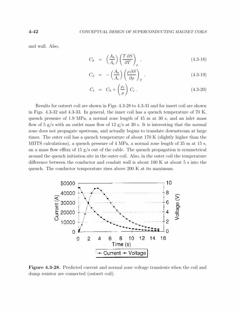
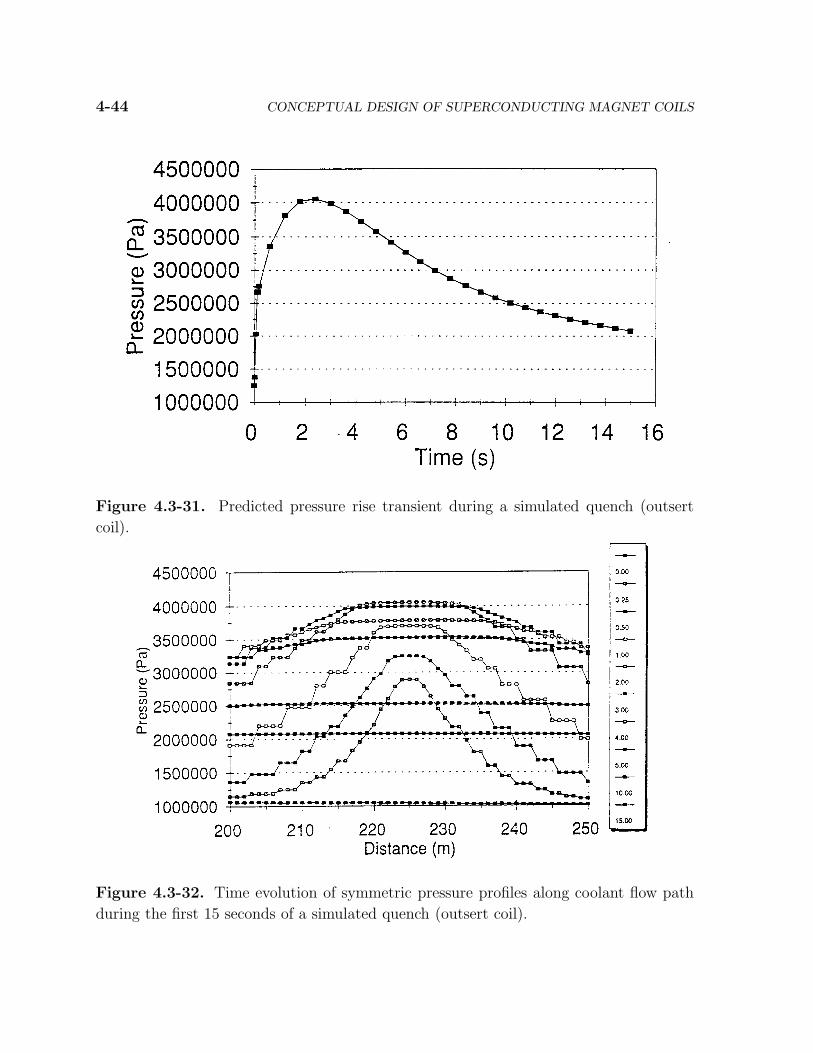
Results for outsert coil are shown in Figs. 4.3-28 to 4.3-31 and for insert coil are shown
in Figs. 4.3-32 and 4.3-33. In general, the inner coil has a quench temperature of 70 K,
quench pressure of 1.9 MPa, a normal zone length of 45 m at 30 s, and an inlet mass
flow of 5 g/s with an outlet mass flow of 12 g/s at 30 s. It is interesting that the normal
zone does not propagate upstream, and actually begins to translate downstream at large
times. The outer coil has a quench temperature of about 170 K (slightly higher than the
MIITS calculations), a quench pressure of 4 MPa, a normal zone length of 35 m at 15 s,
an a mass flow efflux of 15 g/s out of the cable. The quench propagation is symmetrical
around the quench initiation site in the outer coil. Also, in the outer coil the temperature
difference between the conductor and conduit wall is about 100 K at about 5 s into the
quench. The conductor temperature rises above 200 K at its maximum.
Figure 4.3-28. Predicted current and normal zone voltage transients when the coil and
dump resistor are connected (outsert coil).

4.3. DESIGN ANALYSIS 4-43
Figure 4.3-29. Predicted maximum wire and conduit wall temperature rise transient
during a simulated quench (outsert coil).
Figure 4.3-30. Time evolution of symmetric wire temperature profiles along coolant
flow path during the first 15 seconds of a simulated quench (outsert coil).
4-44 CONCEPTUAL DESIGN OF SUPERCONDUCTING MAGNET COILS
Figure 4.3-31. Predicted pressure rise transient during a simulated quench (outsert
coil).
Figure 4.3-32. Time evolution of symmetric pressure profiles along coolant flow path
during the first 15 seconds of a simulated quench (outsert coil).

4.3. DESIGN ANALYSIS 4-45
Figure 4.3-33. Time evolution of asymmetric pressure profiles along coolant flow path
during the first 15 seconds of a simulated quench (insert coil).
Figure 4.3-34. Time evolution of asymmetric wire temperature profiles along coolant
flow path during the first 15 seconds of a simulated quench (insert coil).

4-46 CONCEPTUAL DESIGN OF SUPERCONDUCTING MAGNET COILS
4.4. SUMMARY AND CONCLUSIONS
A superconducting, forced-flow cooled, magnet internal design concept has been devel-
oped to meet the requirements of a stellarator power plant. Results of electromagnetic,
thermal-hydraulic, quench and stability analyses suggest a layer-wound, graded CICC
winding pack configuration with two nested coils offers the promise of design feasibility.
A conceptual point design was developed as a preliminary baseline configuration. The
characteristics of this conceptual point design are summarized in Table 4.4-I.
Several magnet concept development issues beyond the scope of this present study
should be addressed. From a coil design perspective, these open issues are:
1. The minimum bend radius to allowable conduit dimension ratio was assumed to be
20:1 based on best engineering judgment. This ratio needs validation for stellarator-
relevant conductor designs and may require an upward adjustment due to winding
pack twist.
2. A conductor strain of 0.35% was assumed in computing operating margins. Ac-
tual strains may be significantly greater due to combined effects of Lorentz forces,
differential thermal contraction upon cool-down, and stress risers related to local
topology. Consequently, present operating margin predictions may be optimistic.
3. Conduit wall thickness may be undersized, given the extent of conductor bending
combined with quench pressure rise effects.
4. The kinematics of non-planar winding need to be analyzed for this topology and
conductor architecture, and factored into the design of the external case structure.
5. Predicted temperature margins may be under-predicted significantly due to the fact
the cooling design is not optimized.
6. Variability in the local angle of neutron incidence with respect to the coil may effect
peak-to-average nuclear heating factors such that outsert coil hot spot temperature
may increase significantly beyond present values.
7. Electrical transient response of the inductively-coupled, nested coils and case struc-
ture during quench needs to be analyzed from the perspective of how electromag-
netic imbalance forces between coils affect design of the magnet structure.

4.4. SUMMARY AND CONCLUSIONS 4-47
Table 4.4-I.
SPPS/MHH Magnet Internal Design Data Summary
Insert Outsert A Outsert B
Winding window equivalent inside radius (mm) 3,610 3,869 4,145.2
Winding window equivalent outside radius (mm) 3,819 4,113.8 4,390
Winding window lateral width (mm) 505 555 555
Minimum radius of curvature (mm) 340 609 878
Case-to-coil clearance (mm) for groundwall 12 9.6 9.6
Total number of conductor layers 9 8 8
Total number of auxiliary coolant conduit layers 1 0 0
Total number of layers in winding window 10 8 8
Total number of conductor turns per layer 24 18 18
Avg. Total conductor length (m) per year 560 451.4 482.7
Avg. Coolant flow path length (m) per layer 280 451.4 482.7
Total winding window current (MA-turns) 1 6.55 6.55
Total number of turns 216 144 144
Estimated total stored energy (MJ per coil) 13 1200 1,200
Estimated total inductance (H) 1.2 1.2 1.2
Dump resistance (Ω) 0.1 0.33 0.33
Center-tapped winding quench voltage (kV) ±0.25 ±7.5 ±7.5
Number of CICC strands 216 486 486
Nb3Sn strand diameter (mm) 0.62 0.895 0.895
Cu/non-Cu ratio 1:1 2.27:1 2.27:1
Non-Cu area (mm2) 32.6 93.5 93.5

4-48 CONCEPTUAL DESIGN OF SUPERCONDUCTING MAGNET COILS
Table 4.4-II.
Table 4.4-I (Cont’d)
Insert Outsert A Outsert B
Number of cabling stages 4 5 5
Cable space void fraction 0.3 0.35 0.35
Central flow channel diameter (mm) 5 n/a n/a
Peak magnetic field (T) 14.5 9.2 7.3
Operating current (kA) 4.63 45.5 45.5
Predicted minimum temperature margin (K) 0.7 2.1 TBD
QUENCHER predicted quench temperature (K) 70 170 TBD
QUENCHER predicted quench pressure (MPa) 1.9 4 4
Square outer conduit dimension (mm) 16 25.7 25.7
Conduit minimum wall thickness (mm) 1.5 2 2
Conduit inner diameter (mm) 13 n/a n/a
Conduit material type I908 I908 I908
Insulation wrap thickness (mm) 1.25 1.25 1.25
Turn-to-turn spacing (mm) 2.5 2.5 2.5
Layer-to-layer spacing (mm) 2.5 2.5 2.5
Helium maximum mass flow rate (g/s per layer) 8 3.5 TBD
Helium maximum inlet pressure (MPa) 1.25 1.25 TBD
Helium inlet temperature (K) 3 3 3
Helium maximum outlet temperature (K) 5.7 5.2 TBD

4.4. SUMMARY AND CONCLUSIONS 4-49
Steps which can be taken during a subsequent design development effort to address
the aforementioned issues include:
1. Perform experimental conductor bending trials with twist to revise bend radius
limits.
2. Develop a smeared property finite element structural model of an encased non-
planar coil to predict strains due to cool-down and electromagnetic loads.
3. Review recent wire developments, such as tertiary alloys and artificial pinning cen-
ter (APC) technologies, to determine potential gains in critical current density and
applicability to the stellarator power plant.
4. Conduct a manufacturing study of the winding and insulating process.
5. Develop a structural model of conduit and refine wall thickness to account for
strains due to bending and quench pressure rise.
6. Perform a more detailed, self-consistent cooling design study based on steady-state
thermal-hydraulic simulations of the entire winding pack, including case conduc-
tion [29]. Investigate the effects of counterflow coolant routing, case cooling with
conductor effluent, subcooling to 2.5K, and more efficient utilization of the he-
lium heat capacity via optimal selection of coolant inlet pressure and temperature
combinations.
7. Refine MIITS calculation of quench performance, using a nonlinear coupled elec-
trical circuit model of nested coil and case assembly to predict case eddy currents
as well as revise quench voltage and temperature rise. Use prediction of case eddy
currents to determine impact on magnet structural design.
8. Obtain input from wire vendors to assess the extent to which further increases
in Nb3Sn critical current density and processing yields are possible and how such
increases would impact the magnet internal design.

4-50 CONCEPTUAL DESIGN OF SUPERCONDUCTING MAGNET COILS
REFERENCES
[1] D. S . Beard et al., “The IEA Large Coil Task,” Fusion Eng. & Des., 7 (1988).
[2] J. R. Miller, S. W. Van Sciver, et al., “A Design for the Superconducting Out-
sert of a 45-T Hybrid Magnet System Using Cable-in-Conduit Conductors,” IEEE
Transactions on Magnetics, 3:71-77 (1993).
[3] T. Kiyoshi, K. Inoue, et al., “Generation of Magnetic Fields over 20 T Using a Newly
Developed Superconducting Magnet System,” IEEE Trans. Magnetics, 3 (1993) 78.
[4] S. W. Van Sciver, Helium Cryogenics, Plenum Press, NY (1986).
[5] L. Bottura, N. Mitchell, J. V. Minervini, “Design Criteria for Stability in Cable-in-
Conduit Conductors,” Cryogenics, 31 (July 1991) 510.
[6] R. L. Wong, “Thermo-hydraulic Analysis of Superconducting Toroidal-Field Mag-
nets for the Tokamak Physics Experiment,” Adv. In Cryo. Eng., 39 (1994) 1715.
[7] S. K. Singh, Westinghouse Science & Technology Center, private communication
(June 1994).
[8] F. Rau, Max-Planck-Institut fur Plasmaphysik (IPP), Garching, Germany, private
communication (October 1994).
[9] V. Arp, “Forced Flow, Single-Phase Helium Cooling Systems,” Adv. In Cryo. Eng.,
17 (1972) 342.
[10] R. J. Hooper, “Friction Factor Correlations for Cable- in-Conduit Conductors,” Fu-
sion Engineering Design Center report FEDC-M-84-E/M-016, Oak Ridge National
Laboratory (1984).
[11] J. W. Lue, J. R. Miller and J. C. Lottin, “Pressure Drop Measurements on Forced
Flow Cable Conductors,” IEEE Trans. Magnetics, 15 (1979) 53.
[12] Chen-yu Gung, MIT Plasma Fusion Center, private communications (July 1994).
[13] L. El-Guebaly, University of Wissonsin, Madison (October 1994).
[14] G. Morgan, “A Comparison of Two Analytic Forms for the Jc (B,T) surface,” SSC
Tech. Note No. 310-1 (SSC-MD-218), (January 1989).

REFERENCES 4-51
[15] O. R. Christianson, H. L. Chuboy, M. P. Krefta, and S. K. Singh, “High Energy
Booster Dipole Model Magnet (HDMM) Margin,” IISSC, San Francisco, (May 6,
1993).
[16] O. R. Christianson, “Conductor Margin in the SSC Collider Dipole Magnet (CDM),”
Westinghouse STC Doc. 93-8TM4-CDMCD-R1, (July 1, 1993).
[17] M. A. Green, “Calculating the Jc, Bc, Tc Surface for Niobium Titanium Using a
Reduced-State Model,” Proc. 1988 App. Superconductivity Conf., San Francisco,
(August 21-25, 1988).
[18] L. T. Summers, M. W. Guinan, J. R. Miller, and P. A. Hahn, “A Model for the
Prediction of Nb3Sn Critical Current as a Function of Field, Temperature, Strain
and Radiation Damage,” IEEE Trans. Magnetics, 27 (March 1991).
[19] M. N. Wilson, Superconducting Magnets, Oxford Science Publications, (1983).
[20] L. Bottura, N. Mitchell, and J. V. Minervini, “Design Criteria for Stability in Cable-
in-Conduit Conductors,” Cryogenics, 31 (J1991) 510.
[21] F. R. Fickett, “A Preliminary Investigation of the Behavior of High Purity Copper
in High Magnetic Fields,” INCRA Project No. 186 (June 1972).
[22] “User’s Guide to HEPAK Version 3.21,” Cryodata Inc., P. O. Box 558, Niwot, CO
80544.
[23] S. Pourrahimi, C. L. H. Thieme, and S. Foner, “21 Tesla Powder Metallurgy Pro-
cessed Nb3Sn (Ti) Using (Nb-1.2wt%Ti) Powders,” IEEE Trans. Magnetics 23
(1987) 661.
[24] S. Foner, C. L. H. Thieme, S. Pourrahimi, and B. B. Schwartz, “Practical Processing
of A-15 Multifilamentary Superconducting Wire from Powders: Nb3Al and Nb2Sn,”
Adv. Cryo. Eng., 23 (1986) 1031.
[25] G. D. Cody et al., “Phenomenon of Superconductivity,” Air Force Materials Labo-
ratory Report AFML-TR-65-169, Wright-Patterson AFB, Ohio, (June 1965).
[26] M. S. McAshan, “MIITS Integrals for Copper and for Nb- 46.5% Ti,” SSC-N-468
(1988).
[27] A. Shajii and J. P. Freidberg, “Quench in Superconducting Magnets. I. Model and
Numerical Implementation,” J. Appl. Phys., 76 (1994) 3149.

4-52 CONCEPTUAL DESIGN OF SUPERCONDUCTING MAGNET COILS
[28] A. Shajii, and J. P. Freidberg, “Quench in Superconducting Magnets. II. Analytical
Solution,” J. Appl. Phys., 76 (1994) 3159.
[29] T. Kupiszewski and O. R. Christianson, “Predicted Thermal-Hydraulic Character-
istics of Cable-in-Conduit Conductor Windings During Steady-State Operation,”
presented at CEC/ICMC 95, Columbus, OH, (July 1995).