Embed Size (px)
Citation preview

Selected
Superconductivity Program for Electric Systems Office of Power Delivery U.S. Department of Energy• •
January 2000
Prototypes areoutperformingdesign goals
full-scale utilityapplications are movingonto the power system and ...
High-Temperature SuperconductingElectric Power Products
Modernizing theExisting Electricity
Infrastructure

1
(Courtesy of American Superconductor Corp.)
Flexible HTS conductors promise reducedoperating costs and many other benefits whenincorporated into electric power devices. Theycan change the way power is managed andconsumed.
Contents
� HTS Power Products Capture the Attention ofUtility Engineers andPlanners . . . . . . . . . . . . . . . . . . . . . . . . . . . 1
� Transforming Transformers . . . . . . . . . . . . 3
� Surge Protection for Power Grids . . . . . . . . 6
� High-Capacity Transmission Cables . . . . . 8
� Unleashing HTS Horsepower . . . . . . . . . . 11
� For More Information . . . . . . . . . Back Cover
HIGH TEMPERATURE SUPERCONDUCTING POWER PRODUCTS CAPTURE THEATTENTION OF UTILITY ENGINEERS AND PLANNERS
Soon superconductors could be so common that we will drop the �super� and refer to themsimply as conductors
Critical Role of Wire
The application of superconductors to electricpower systems has been pursued for more than 30years. This persistence is starting to pay off andutilities that once politely acknowledged thelong-term potential of superconductingapplications are now paying close attention toseveral prototype devices that are being tested orare nearing testing on utility systems. What hasprompted this interest is the development ofelectric wires that become superconducting whencooled to the affordable operating-temperaturerealm of liquid nitrogen as well as thedevelopment of coils, magnets, conductors, andmachines and power components made with thesewires. Superconducting wires have as much as100 times the current carrying capacity asordinary conductors.
A Real Need
The timing is right for superconducting solutionsto emerging business problems. Powergeneration and transmission equipment is agingand must be replaced. Environmentalconsiderations are increasing. Utilities arechanging the way they evaluate capitalinvestments. Deregulation is intensifyingcompetition. Superconducting power productswill help the industry meet these challenges byreducing operating costs, enhancing flexibilityand reliability, and maximizing the capability ofour existing infrastructure. This ultimately couldbe reflected in lower electricity rates forcustomers.
Utility Uses
The following pages present technical profiles andspecifications for four high-temperaturesuperconducting (HTS) power products that are inthe demonstration phase and are likely to gain afoothold in the marketplace. They are:transformers; current controllers; transmission

2
Department of EnergySuperconductivity Program Goals
� PERFORMANCE � Develop HTS wires with 100 times
capacity of conventional copper/aluminum wires
� Design broad portfolio of electricequipment based on HTS- 50% size of conventional units with
same rating - 50% reduction in energy losses
compared to conventional equipment
� COST � Wire cost $0.01/ampere-meter� Equipment premium cost payback
(efficiency savings) in 2-5 years ofoperation
� Equipment total cost payback duringoperating life
cables; and large motors. These prototypes areproviding the technical data and valuableoperating experience base needed to acceleratethe acceptance of superconducting technologiesand to open up vast global markets.
Modernizing the Infrastructure
The general acceptance of superconductingpower equipment by the electric utilities andother end-users will ultimately be based on therespective system performance, efficiency,reliability and maintenance, operational lifetime,and installed cost compared to conventionaltechnologies. High-temperaturesuperconductivity can fundamentally reshapethe technology of electricity delivery based onthe results of full-scale demonstrations in keyapplications, including transformers, currentcontrollers, cables, and motors.
U.S. Program
The U.S. Department of Energy (DOE) supportsnational energy, economic, environmental andeducational interests by providing leadership indeveloping HTS electric power devices andfacilitating their adoption by the utility industryand private sector. (See the text box for theprogram goals.) The HTS prototypedemonstrations described here are cost-sharedthrough the DOE Superconductivity Program�sSuperconductivity Partnership Initiative (SPI).

3
(Courtesy of Waukesha Electric Systems)
TRANSFORMING TRANSFORMERS
Use of HTS windings will turn power transformers into compact, environmentally friendlyand highly efficient performers that will help deliver high quality power cost effectively.
HTS transformers use windings made ofsuperconducting tape instead of conventionalcopper or aluminum. The HTS tapes becomesuperconducting at about 120 K and below. Thetapes are usually cooled to liquid nitrogentemperatures (77 K, or -196 C) or lower too
achieve best performance. At these temperaturesthe superconducting tapes allow current to betransported with nearly zero resistance.However, HTS transformers must still cope witheddy and ac losses in the windings that requirerefrigeration power. These losses are smallcompared to losses due to resistive heating inconventional transformer windings. HTStransformers offer the possibility of operatingwith low losses and at 10 to 30 times greatercurrent density than conventional transformers. The windings are electrically insulated withdielectric materials which are designed to meetANSI standard dielectric tests for system voltagesand the associated basic impulse insulation testlevels.
System Advantages
HTS transformers have potential advantages overconventional transformers in the following areas:about 30% reduction in total losses, about 45%lower weight, and about 20% reduction in totalcost of ownership. These advantages are basedon a 100 MVA transformer with HTS wireproviding a critical current density of 10 kA/cm2
and AC losses of 0.25 mW/A-m in a parallel fieldof 0.1 tesla. Additional benefits include:unprecedented fault current limiting functionalitywhich is expected to protect and reduce the costof utility system components, and reducedoperating impedance which will improve networkvoltage regulation. In addition to greaterefficiency than conventional transformers, HTStransformers eliminate oil cooling, thus reducingfire and environmental hazards associated withoil-based systems. These benefits enable HTStransformers to have higher power densities sothey can be sited in high-density urban areas andinside buildings.
Greater Effective Capacity
Utility engineers envision the benefits of HTStransformers and how they could solve substationproblems. Ronald C. Johnson, substationsengineer at Rochester Gas & Electric Corp. states,�HTS transformers are attractive . . . because theyare much smaller, have greatly extended overloadcapability and don�t have fire and environmentalproblems associated with insulating oil.� RobertH. Jones, senior engineer at RG&E adds, �Ourtypical substation is designed with twotransformers. If one transformer fails, the other issized to carry the load of both during theemergency. An HTS transformer can carry up to200 percent of nameplate rating indefinitelywithout loss of transformer life. This means wecan buy transformers of lower rating to do thesame job or pack up to four times the capacityonto the same footprint area. HTS is abreakthrough technology that promises to bringsweeping changes to transformers.�
4
Table 1. Examples of Potential Financial Benefits.(The numbers provided are typical industry averages)
HTS Transformer Characteristic FinancialBenefits
Current Limiting Capacity� Use conventional breaker instead of high current SF6 breaker� Replace EHV breaker with circuit switcher� Use load break switches instead of breakers� Elimination of current limiting reactors
$25,000 each$25,000 each$ 6,000 each$20,000 each
Reduced Impedance(*): Impact on Power System� Reduced need for Load Tap Changer units (voltage regulation)� Reduced system VAR requirements (Static VAR
Compensation)� Reduction in capacitor banks (reduced reactive power losses)
$75,000 per LTC$50,000 per MVAR
$13,000 per 10 MVA
Reduced Transformer Impedance (*): Impact on Generation
� Reduced VAR requirements freed up for system, at $50/kVARAdditional available generator capacity from improved operation:25 MW1. Avoided capital cost, at $300/MW for gas turbine generator2. Additional revenue, at $0.04/kWh, 50% capacity factor
$2.5 million
$7.5 million$4.4 million (annual)
(*) Assumed: HTS transformer impedance is 25% of that of conventional transformer
Table 2. 1-MVA Experimental HTS Transformer Coreand Coil Assembly Design
Parameter SpecificationRoot mean square voltage and current 13.8/6.9 kV, 72.5/145 Amps
Cold mass weight ~ 590 kg (1,300 lb)
Vacuum tank volume 21,600 liters
Vacuum tank dimensions (hxwxd) 3.79 m x 2.78 m x 2.05 m
Vacuum tank weight 8,774 kg (19,300 lb)
Liquid nitrogen tank capacity 300 liters
Weight of liquid nitrogen tank and shield 364 kg (800 lb)
Cryocooler rating (Cryomech GB-37) 30 W at 25 K
Core weight 8,000 kg (17,600 lb)
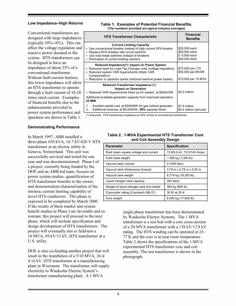
Low Impedance�High Returns
Conventional transformers aredesigned with large impedances(typically 10%-16%). This canaffect the voltage regulation andreactive power demand in thesystem. HTS transformers canbe designed to have animpedance of about 25% of aconventional transformer. Without fault-current limiters,this lower impedance will allowan HTS transformer to operatethrough a fault current of 10-20times rated current. Examplesof financial benefits due to theenhancements provided topower system performance andoperation are shown in Table 1.
Demonstrating Performance
In March 1997, ABB installed athree-phase 630 kVA, 18.7 kV/420 V HTStransformer at an electric utility inGeneva, Switzerland. This unit wassuccessfully serviced and tested for oneyear and was decommissioned. Phase I ofa project, currently being funded by theDOE and an ABB-led team, focuses onpower system studies, quantification ofHTS transformer benefits to the owner,and demonstration/characterization of theintrinsic current limiting capability ofnovel HTS conductors. This phase isexpected to be completed by March 2000. If the results of these market and systembenefit studies in Phase I are favorable and sowarrant, this project will proceed to the nextphase, which will include specification anddesign development of HTS transformers. Theproject will eventually aim to field-test a10 MVA, 69 kV/13 kV, HTS transformer at aU.S. utility.
DOE is also co-funding another project that willresult in the installation of a 5/10 MVA, 26.4/4.16 kV, HTS transformer at a manufacturingplant in Wisconsin. The transformer will supplyelectricity to Waukesha Electric System�stransformer manufacturing plant. A 1 MVA
single-phase transformer has been demonstratedby Waukesha Electric Systems. The 1 MVAtransformer is a test bed with a core cross-sectionof a 30-MVA transformer with a 138 kV/13.8 kVrating. The HTS winding can be operated at 25-77 K and the core is at near room temperature. Table 2 shows the specifications of the 1-MVAexperimental HTS transformer core and coilassembly. The test transformer is shown in thephotograph.

5
1-MVA demonstration transformer (Courtesy of Waukesha Electric Systems)
Partners
ABB Power T&D Company, Inc. Team:American Superconductor Corp., Air Productsand Chemicals, American Electric Power,Southern California Edison, Los Alamos NationalLaboratory.
Waukesha Electric Systems Team:Intermagnetics General Corp., Rochester Gas &Electric, Oak Ridge National Laboratory,Rensselaer Polytechnic Institute

6
The cryomagnetic subsystem contains theworld�s largest HTS coil. (General Atomics)
SURGE PROTECTION FOR POWER GRIDS
HTS current controllers will provide utilities with surge protection within their local powerdistribution systems. They will prove to be economical and efficient fault-current limiters.
Old Problem
Every lightning strike, short circuit and powerfluctuation is a potential catastrophe for powercompanies and their customers. These commonevents cause fault currents, which are sudden,momentary surges of excess energy or currentthat can damage and destroy expensivetransmission and distribution equipment�and cutoff service throughout a utility�s grid.
New Solution
Utilities overwhelmingly indicate a critical needfor a highly efficient current limiter. Yet feware satisfied with conventional solutions, whichinclude larger, more costly transformers,inefficient current-limiting reactors and single-use fuses. HTS current controllers are far morecapable than conventional solutions in severalcritical ways. They are reusable, requireminimal maintenance, and do not needreplacement after being activated. Mostimportantly, they also allow utilities to increaseline power capacity and make more effectiveuse of the grid.
Andrew Power of the UK�s National GridCompany believes, �The most excitingapplication of superconductors is in fault currentlimiters. HTS fault current limiters will provide the T&D industry with a solutionthat is impossible with conventionaltechnology.�
Superconductors are natural fault currentlimiters because of their ability to changerapidly from a superconducting, zero impedancestate to a normal high impedance state in a faultsituation.
In this way, an HTS current controller can detecta power surge and redirect it to an HTS coil thatcan safely absorb the surge without tripping thecircuit breakers. This device limits the impact
of a fault current, ensuring uninterrupted powersupply to the grid's customers, and protectingutility equipment. HTS fault current limiters arecompatible with existing protection devices. Their maximum allowable current is adjustable,which means greater system flexibility and theycan defer the need for transmission anddistribution system upgrades.
Prototype Exceeds Design Goals
The DOE is funding a project that will develop a15 kV, 45 kA (asymmetric) pre-commercialcurrent controller. In the first phase of thisproject the prototype surpassed most of its designgoals. The 15 kV prototype device was built andactually rated at 17 kV, 45 kA, and 765 MVA. Itoperated at 40 K and experienced a peakmagnetic field in normal operation of 0.3 Tesla(T) and peak magnetic field in fault conditions of1.4 T. While the coil's normal operating currentis 2,000 A dc, it is able to handle 9,000 A rmsduring the fault condition.
In an early project test, the prototype 2.4 kVcurrent controller successfully reduced a 3.03 kAfault current, performing 37% above

7
Table 3. 15 kV Fault Current LimiterDevice Design
Parameter SpecificationMaximum operating voltage 17 kV rmsNormal operating current 1,200 Amps rmsMaximum interceptable current 45 kA (asm)Breakdown insulation level 110 kVMaximum ambient temperature 323 KDesigned fault reduction 80%Fast breaker operation 8 msMultiple fault limiting Two faults, 1s each
15 s apart
Table 4. 15 kV Fault Current Limiter CoilCharacteristics
Parameter SpecificationConfiguration 1.0 m OD/0.75 m height
solenoidOperating temperature 40 KInductance 5 mHNominal operating current 2,037 AdcMaximum fault current 9,000 A rmsMaximum terminal voltage 20 kV (rated)Maximum radial field 0.37 T normal operation
1.4 T fault condition
Table 5. 15 kV Fault Current LimiterSubsystem Characteristics
Parameter SpecificationPowerelectronics
96 5.2 kV, 3 kA thyristors144 heat sinks300 gallons/minute oil cooled heatexchanger
Cryogenics 9 cryocoolersVacuum insulated
Controlsubsystem
Self diagnosisAutonomous operation
Interface withutilities
NEMA enclosureTrailer mounted
The superconducting current controller wasdelivered to the Southern California EdisonCenter Substation for testing. (GeneralAtomics)
specifications. The specifications also calledfor the current controller to be able to handle 2faults of 400 ms each, spaced 15 seconds apart. The prototype limited these fault currents withinan interval of less than one second. The currentcontroller also worked as a fast half-cyclecircuit breaker. The 2.4 kV current controllerwas successfully tested in September 1995 at aSouthern California Edison substation. The15 kV controller was shipped to SouthernCalifornia Edison in 1999. The photographshows the controller being transported to theCenter substation on a 40-foot trailer. Tables 3,4, and 5 show the specifications of the faultcurrent controller.
During high voltage tests, a flash to ground in anauxiliary piece of equipment rendered one phaseinoperable and single-phase testing continued onthe controller. During these tests, the prototypeachieved fault reduction and a sub-cycle fastbreaker operation at 12.47 kV and 10 kA. Testing has been terminated though the HTScoils are still fully operable. Proposed workincludes the study and repair of the prototypeand modifications to the cryogenic system toimprove its reliability.
Partners
General Atomics, Southern California EdisonIntermagnetics General Corporation, Los AlamosNational Laboratory, California EnergyCommission, EPRI.

8
Warm-Dielectric Cable DesignEPRI
HIGH-CAPACITY TRANSMISSION CABLES
HTS cables cooled to 77 K are being demonstrated and will soon be carrying at least 3 to 5times more than conventional cables through the existing underground city pipes. This offersstrategic benefits to utilities and a cost-effective means for repowering the existing electricitydelivery infrastructure.
New Possibilities
Network designers have traditionallyincreased voltage to transmit morepower efficiently. For a given capacity line, higher voltage results inlower current and lower ohmic (I R)2
heating losses. That has entailedlarge investments in high-voltagetransformers and related equipment,as well as large electric losses. HTScables may make it possible to lay outgrids in innovative ways to positiongenerators closer to customers,without having to step voltage up anddown as frequently as is done today. The economic savings would beformidable.
Growing with the Grid
Presently about one-quarter of the 2,200 milesunderground transmission cables in the U.S. havebeen in place beyond their rated lifetimes. HTScables can meet increasing power demands inurban areas via retrofit applications usingexisting cable conduits and can eliminate theneed to acquire new rights-of-way. Presently,two to three underground copper cables areneeded to achieve the capacity of one overheadtransmission line and installation costs are 20 to30 times higher.
In HTS power transmission cables, conventionalconductor wire of copper or aluminum is replacedby HTS wire, enabling the cable to carry greateramounts of current with lower resistive losses. Successful application of HTS conductors totransmission cables would allow the use ofunderground HTS cables for the replacement ofoverhead lines. Significant environmentalbenefits are obtained from the use of liquidnitrogen coolant rather than oil.
Two basic HTS cable designs are emerging aspossible candidates for power transmission.
Warm-Dielectric Design
One design by Pirelli uses a �room temperaturedielectric� material, in which the dielectric(electrical insulation) is outside the thermalinsulation and is not exposed to liquid nitrogentemperatures. This simplifies the designconsiderably since conventional dielectrics canbe used. The overall assembly consists of aflexible, hollow core wrapped with several layersof HTS tape, followed by thermal and electricalinsulation. Pressurized liquid nitrogen flowsthrough the core to cool the HTS tape. The cableassembly is then jacketed in the conventionalmanner and completed with skid wire to providephysical protection during cable installation anduse.

9
Cold-Dielectric Cable Design
In 1996, a successful 50-m cable, carrying 3,300A dc, at 1 �V/cm dc, and 77 K, wasdemonstrated. In 1998, a 50-m cable prototypewas successfully tested at 115 kV, includingterminal connections and a splice. This cablewas operated at 69 kV and carried 3,300 A dc at74 K and can carry up to 2000 A ac.
Detroit Edison Project
The DOE and Pirelli are co-funding a project todevelop and manufacture a 120-m, 24 kV, threephase HTS cable prototype and test it usingconventional, industry-accepted techniques. Three such cables will be installed in DetroitEdison�s Frisbie substation by 2001. The cablescan carry 2,400 A ac at temperatures of 77 K(-196 C). Cooling is done by liquid nitrogeno
circulating in a hollow core. This is three timesthe current carrying capacity of a comparablecopper cable. The cables will be installed in 4-inch (10-cm) diameter ducts. The HTS cable willreplace three conventional circuits in thesubstation. This real application will use only110 kg of superconducting wire to conduct asmuch power as the 8,200 kg of copper wire itreplaces.
Energy Secretary Bill Richardson said the projectwould open �the gateway to the electricitysuperhighway of the future.� Robert Buckler,president and COO of DTE Energy Distributionsaid, �Having the capability to triple the current-
carrying capacity of existing conducts will allowus to avoid digging up and disrupting theinfrastructure.� As urban areas are revitalized,these cables will be able to bring in the extrapower and also increase system reliability. Competitive retail markets will place greaterpower transfer demands on regional and urbannetworks.
Bill Carter, Detroit Edison�s director oftransmission and subtransmission planningremarked, �We will be one of the first utilities toget O&M experience with liquid nitrogen-cooledHTS power technology�something we believewill be of significant value as HTS cable andother power products enter the commercialmarket.� Adds Buckler, �This demonstrationproject will encompass most of what we expect toencounter in the future if we decide to pursue amajor HTS retrofit strategy. Our people areexcited at the prospect of learning how to do theirwork using the new, cutting-edgesuperconducting technology.�
Cold-Dielectric Design
In another design variation, Southwire Companyis developing a �cryogenic dielectric� designwhich exposes the cable�s electrical insulation toliquid nitrogen temperatures. This design offersthe added benefit of the dielectric acting as ashield to the HTS tapes, which lowers ac lossesand eliminates the external electromagnetic field.
10
In this design, a central former is concentricallysurrounded with HTS tape, electrical insulation,and another layer of HTS tape. The entireassembly is then insulated and jacketed to protectit from thermal and physical damage. The cableis cooled by passing liquid nitrogen through thehollow central former along the length of thecable, which is then returned, through gaps in anouter layer of the cable assembly.
Southwire SPI Project
The Southwire project resulted in a 30-m, threephase, 12.5 kV, 1.25 kA, power cable installedin Carrollton, Georgia. The cable powers twomanufacturing plants and a corporateheadquarters. Southwire Company hadpreviously tested a 5-meter, single phase HTScable successfully. This demonstration cable iscapable of carrying 1,400 Amps, which exceedsthe design goal and has demonstrated stableoperation at design parameters (7.2 kV ac and1,250 Amps). The tests on this first 5-m cableprovided a number of valuable insights, includingthe following:
� Measurements of dc critical have been madefrom 72 - 82 K
� AC losses are on the order of 1 watt/m atoperating temperature
� The cable can maintain its integrity at up to2.5 times the operating voltage (18 kV) acand at ac currents of up to 1,400 Amps.
� The cable has been operated at the designparameters of 7.2 kV and 1,250 Amps ac forover 72 hours.
The three phase, 30-m cable powers Southwire�sown corporate headquarters and manufacturingfacility. R.L. Hughey, Southwire projectmanager said, �The HTS cable will be used underreal-world conditions, including varying loads. The load is estimated to be equivalent to thatrequired for the city of Carrollton [about 18,000people].� He added, �The Southwire cable is theworld�s first industrial field test of an HTS powerdelivery system. We�re developing a cable whichutility companies will use to distribute energy tohomes and businesses that will be capable ofhandling the power demands of the newmillennium and beyond.�
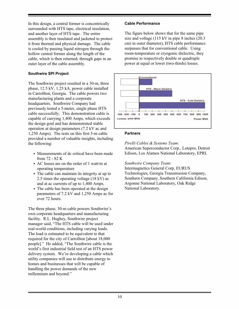
Cable Performance
The figure below shows that for the same pipesize and voltage (115 kV in pipe 8 inches (20.3cm) in outer diameter), HTS cable performancesurpasses that for conventional cable. Usingroom-temperature or cryogenic dielectric, theypromise to respectively double or quadruplepower at equal or lower (two-thirds) losses.
Partners
Pirelli Cables & Systems Team:American Superconductor Corp., Lotepro, DetroitEdison, Los Alamos National Laboratory, EPRI.
Southwire Company Team:Intermagnetics General Corp, EURUSTechnologies, Georgia Transmission Company,Southern Company, Southern California Edison,Argonne National Laboratory, Oak RidgeNational Laboratory.

11
UNLEASHING HTS HORSEPOWER
Big outputs come in small packages due to revolutionary electric motors that use HTStechnology to maximize performance while reducing size, weight and energy costs.
Electric motors run the industrialized world.They also run huge power bills�$55 billion a yearin the U.S. alone. Industrial motors of more than1,000 hp consume about 20% of all electricpower generated in the U.S. As industry looksfor ways to cut expenses, one of the mostpromising solutions lies in the HTS motors.
Immediate Savings
Industrial electric motors consume 70% of theelectricity used in a typical manufacturingoperation, so increased efficiency yieldsimmediate savings in power costs. Each onepercent in efficiency improvement provided byHTS motors would result in an estimated savings(across all motors of over 1,000 hp) of more than$300 million per year in the U.S. Over thelifetime of the HTS motor, the savings in powercosts would exceed its capital cost. Reduced sizeand weight additionally cut costs associated withshipping, manufacturing, installing, andmaintaining motors. More efficient operationalso conserves non-renewable resources andgenerates fewer pollutants and greenhouse gases.
Basic Design
HTS motors can replace large motors(> 1,000 hp) for pump and fan drives in utility andindustrial markets. The HTS motor beingdeveloped by Reliance Electric, a division of theRockwell Automation Company is acryogenically cooled, ultra-efficient synchronousmotor with HTS field windings. The adjustablespeed drive (ASD) used to power the motor willbe a conventional rectifier/inverter system asused with present AC induction motor products,modified to operate with a synchronous motor. The HTS field winding will operate in the 25 - 40K temperature range at a DC magnetic field of upto 4 Tesla. The field coils will be cooled by acommercially available cryocooler system thatfeeds cooled helium gas to and receives warmedhelium gas from the rotor. Much of Reliance
Electric�s work today is geared to accommodateprogress on the HTS materials front. DavidDriscoll, superconducting motors manager said,�All the engineering we�re doing today to get amotor at 1,000 hp at 33 K will only help us in thefuture, when we have wire that will actually beperforming [at high field] at 77 K.�
The HTS motor components are shownschematically on the next page. In plannedcommercial models, the magnitude of themagnetic field is approximately twice that of aconventional motor. The HTS motor has an aircore (i.e. nonmagnetic) construction so that theair gap field can be increased without the coreloss and saturation problems inherent in alaminated iron stator and rotor core. The copperarmature winding lies just outside the air gap.
Under steady state operation, the rotor spins insync with the rotating field created by thethree-phase armature currents and thesuperconducting field winding experiences onlyDC magnetic fields. Under load or sourcetransients, however, the rotor will move withrespect to the armature-created rotating field, andit will experience AC fields. The AC fields areshielded from the HTS field winding by warmand cold AC flux shields located between theHTS coils and the stator winding.
Inside the warm outer AC flux shield will be athermal insulation space (vacuum) that willsurround the rotor cryostat. The cold AC fluxshield is on the inside surface of this vacuumspace and is a high-conductivity shell near theoperating temperature of the superconductingcoils. The superconducting field coils are locatedwithin the inner shield on a non-magnetic supportstructure.

12
HTS Motor: Design Features (Reliance Electric)
Table 6. HTS Motor SpecificationsCoil Assembly Design
Parameter Value for1,000 hp
Motor
Value for5,000 hp
MotorOutput power (hp)/(kW) 1,000/746 5,000/3,730Shaft speed (rpm) 1,800 1,800Output torque (ft-lb)/(N-m) 2,918/3,956 14,589/19,780Number of poles 4 4Armature voltage (V) 4,160 4,160Power factor 1.0 1.0Predicted efficiency (% wo/ref) 97.9 98.8Predicted efficiency (% w/ref) 97.1 98.6Operating field current (Amps) 126 152Operating field temperature (K) 33 33Current density, J (kA/cm )c
2 13.5 13.5Maximum field magnetic flux (T) 1.5 1.85kA-turns/pole 172 327Rotor outer diameter (in)/(cm) 15.8/40.1 24/60.7Armature outer diameter (in)/(cm) 27/68.6 38/96.5Armature length (in)/(cm) 48/121.9 50/127
Benefits
HTS motors may increase machine efficiencybeyond 98%, reducing losses by as much as 50%compared to conventional motors. HTSmotors are smaller in size occupyingapproximately half the volume and mayhave lower life cycle costs.
Motor Surpasses Design Goals
The DOE is co-funding a project that willbuild and test a 1,000 hp HTS motor in2000 and a 5,000 hp HTS motor by 2002. In March 1996, a 200-hp motor wasdemonstrated which exceededspecifications by 60%. This was the firstair-core synchronous motor with rotatingsuperconducting field coils cooled byhelium gas. The 1,000-hp motor has beenbuilt and is being tested. The performance of theHTS coil did not degrade under the mechanicalstresses associated with rotational force. �Thisfirst of a kind HTS motor will undergo extensivetesting and evaluation in our laboratory,� statedPaul T. Gorski, Vice President of Engineering atRockwell Automation Power Systems group. �Atthe conclusion of these laboratory tests, we planto place this motor in an industrial beta site while
we manufacture the 5,000 horsepower motorwhich is being targeted as the commercial entrypoint for this product.�
Table 6 shows the HTS motor specifications forthe 1,000 and 5,000 hp motors.
Partners
Rockwell Automation/Reliance Electric,American Superconductor Corp., Air Productsand Chemicals, Centerior Energy, Sandia NationalLaboratory, EPRI.

13
NOTICE: This report was prepared as an account of work sponsored by an agency of the United Statesgovernment. Neither the United States government nor any of their employees, makes any warranty, express orimplied, or assumes any legal liability or responsibility for the accuracy, completeness, or usefulness of anyinformation, apparatus, product, or process disclosed, or represents that its use would not infringe privately ownedrights. Reference herein to any specific commercial product, process, or service by trade name, trademark,manufacturer, or otherwise does not necessarily constitute or imply its endorsement, recommendation, or favoring bythe United States government or any agency thereof. The views and opinions of authors expressed herein do notnecessarily state or reflect those of the United States government or any agency thereof.
High-Temperature Superconducting Electric Power Products
was prepared by Energetics, Incorporated.under subcontract number 62X-5V815Cwith Lockheed Martin Energy SystemsCompiled and written by Joseph Badin.
January 2000
For more informationabout HTSContact:
For more informationabout HTSContact:
TransformersSam MehtaWaukesha Electric Systems414-547-0121 ext. [email protected]
V. R. [email protected]
TransformersSam MehtaWaukesha Electric Systems414-547-0121 ext. [email protected]
V. R. [email protected]
Current ControllersEddie LeungGeneral [email protected]
Current ControllersEddie LeungGeneral [email protected]
CableR. L. HugheySouthwire [email protected]
Nathan KelleyPirelli Cables North [email protected]
CableR. L. HugheySouthwire [email protected]
Nathan KelleyPirelli Cables North [email protected]
MotorDavid DriscollRockwell [email protected]
MotorDavid DriscollRockwell [email protected]
www.eren.doe.gov/superconductivitywww.eren.doe.gov/superconductivity
. .
U.S. Department of EnergyU.S. Department of Energy
James DaleySenior Program [email protected]
Roland George2nd Generation [email protected]
Harbans ChhabraSuperconductivityPartnership [email protected]
James DaleySenior Program [email protected]
Roland George2nd Generation [email protected]
Harbans ChhabraSuperconductivityPartnership [email protected]