Embed Size (px)
Citation preview
8/3/2019 2011 EL Wearable+Dual Band+Sierpinski+Fractal+PIFA+Using+Conductive+Fabric
http://slidepdf.com/reader/full/2011-el-wearabledual-bandsierpinskifractalpifausingconductivefabric 1/2
Wearable dual-band Sierpinski fractal PIFAusing conductive fabric
P.J. Soh, G.A.E. Vandenbosch, S.L. Ooi and M.R.N. Husna
A novel planar inverted-F antenna (PIFA), incorporating a triangular Sierpinski gasket, is presented. The used conducting textile and poly-ester eece allow easy on-body integration and simple practical fabri-cation. It shows dual-band response, combining a 16 % band at 2.45 GHz with an upper 12 % band at 5.2 GHz. The broadside gainis 3.1 dBi. Good agreement between calculated and measured data isobserved.
Introduction: Antennas to be integrated on-body are crucial in cateringfor various future 802.15 wireless standards. The main barrier to imple-menting these antennas is usually the degraded performance when oper-ating in proximity of the body, e.g. the reduced bandwidth. Large bandwidth or dual-band behaviour is needed in multi-application wire-less devices. Several techniques have been implemented to broaden the bandwidth, including the introduction of slots [1, 2], folding and rollingup of larger elements [3, 4], addition of parasitic elements [5], and in-tegration of several radiators into a single structure [6, 7]. An effectiveway to generate dual- and multi-band frequency response is usingfractal Sierpinski topologies. However, gasket monopoles, in whichthese structures are traditionally implemented, limit a planar implemen-
tation on a small physical area [8]. Incorporating the structure into a planar inverted-F antenna (PIFA), which is the key novelty in thisLetter, provides a means of planar implementation.
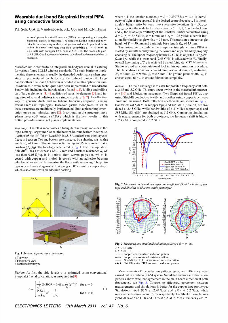
Topology: The PIFA incorporates a triangular Sierpinski radiator at thetop,a rectangular groundplaneat thebottom, bothmade from the conduc-tive fabricShieldIt TM from LessEMF Inc,USA,and a 6 mm-thicklayer of eece in between. Top and bottom are connected bya shorting wall with awidth W s of 4 mm. The antenna is fed using an SMA connector at a position ( f V , f H ). The topology is depicted in Fig. 1 . The rip-stop fabricShieldIt TM has a thickness t of 0.17 mm and a surface resistance Rs of less than 0.05 V / sq. It is derived from woven polyester, which iscoated with copper and nickel. It comes with an adhesive backingwhich enables secure placement on the eece without sewing. The proto-type is benchmarked against a PIFA using a 0.035 mm-thick copper tape,
which also comes with an adhesive backing.
a c
f H
f V
D
G L
S or R W
b
fleecesubstrate
groundplane
radiator
WS
Fig. 1 Antenna topology and dimensionsa Top viewb Perspective viewc Fabricated prototype
Design: At rst the side length s is estimated using conventionalSierpinski fractal calculation, as proposed in [9]
s =1
3√ (0.3069 +0.68r x) c f c
(j −1)n for n =0
0.52
3√ c
f cd n −
h
1 r √ for n . 0(1)
where n is the iteration number, r ¼ j 2 0.230735, x ¼ 1, c is the vel-ocity of light in free space, f c is the desired centre frequency, j is the tri-angle’s height ratio between two successive iterations ( j ¼ Diter(n) / Diter(n + 1) ), d is the scale factor, also given by d ¼ 1/ j , h is the thicknessand 1 r the relative permittivity of the substrate. Initial calculation usingd ¼ 2, f C
¼ 2.45 GHz, h ¼ 6 mm, and e r ¼ 1.26 yields a zeroth iter-ation Sierpinski triangle with s ¼ 35 mm. This translates into a triangleheight of D ¼ 30 mm and a triangle base length RW of 35 mm.
The procedure to combine the Sierpinski triangle within a PIFA isstarted by simultaneously tuning the lower and upper band by properlychoosing D. The upper frequency band (5.2 GHz) is adjusted using Rw, f H , and f V , while the lower band (2.45 GHz) is adjusted with W s . Finally,overall ne-tuning of S 11 is achieved by modifying G L . CST MicrowaveStudio is used as a computational tool in this optimisation procedure.The nal dimensions are D ¼ 24 mm; Rw ¼ 34 mm, G L ¼ 44 mm,W s ¼ 4 mm, f V
¼ 9 mm, f H¼ 8.5 mm. The ground plane width G W is
chosen equal to RW to ensure fabrication simplicity.
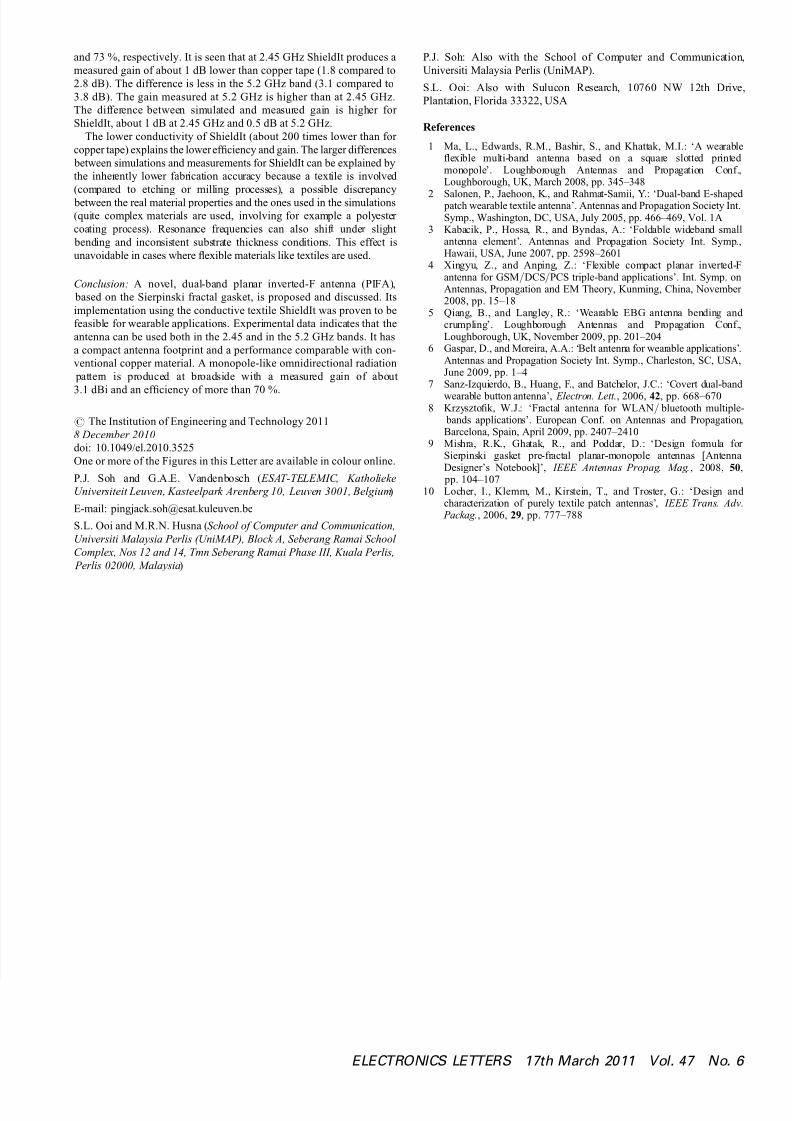
Results: The main challenge is to cater for possible frequency shift bothat 2.45 and 5.2 GHz. This may occur owing to the material inhomogen-eity [10] and fabrication inaccuracy. Two Sierpinski fractal PIFAs, oneusing ShieldIt conductive textile and another using copper tape, were built and measured. Both reection coefcients are shown in Fig. 2 .Bandwidths of 570 MHz (copper tape) and 345 MHz (ShieldIt) are pro-duced at 2.45 GHz, while bandwidths of 615 MHz (copper tape) and
585 MHz (ShieldIt) are obtained at 5.2 GHz. Comparing simulationswith measurements for both prototypes, the frequency shift is higher at 2.45 GHz compared to 5.2 GHz.
1.5 2.0 2.5 3.0 3.5 4.0 4.5 5.0 5.5 6 .0 6.5 7.0–36–34–32–30–28–26–24–22–20–18–16–14–12–10
–8–6–4–2
02
S 1 1 ,
d B
frequency, GHz
ShieldIt PIFA sim. S 11ShieldIt PIFA meas. S 11copper tape PIFA sim. S 11copper tape PIFA meas. S
11
Fig. 2 Measured and simulated reection coefcient (S 11 ) for both copper tape and ShieldIt conductive textile prototypes
–4.0–3.5–3.0–2.5–2.0–1.5–1.0–0.5
0.00.5
030
60
90
120
150180
210
240
270
300
330
–4.0–3.5–3.0–2.5–2.0
–1.5–1.0–0.5
0.00.5
–18–16–14–12–10
–8–6–4–2
02
030
60
90
120
150180
210
240
270
300
330
–18–16–14–12–10
–8
–6–4–2
02
a b
Fig. 3 Measured and simulated radiation patterns ( f ¼ 0 8 cut)a At 2.45 GHz,b At 5.2 GHz – – – copper tape simulated radiation pattern-o-o- copper tape measured radiation pattern —— ShieldIt textile PIFA simulated radiation pattern-O -O ShieldIt textile PIFA measured radiation pattern
Measurements of the radiation patterns, gain, and efciency werecarried out in a Satimo SG-64 system. Simulated and measured radiation patterns show excellent agreement in the main beam direction at both
frequencies, see Fig. 3 . Concerning efciency, agreement betweenmeasurements and simulations is better for the copper tape prototype.Simulations yield 93% at 2.45 GHz and 89% at 5.2 GHz, whilemeasurements show 86 and 78 %, respectively. For ShieldIt, simulationsyield 90 % at 2.45 GHz and 93 % at 5.2 GHz. Measurements yield 75
ELECTRONICS LETTERS 17th March 2011 Vol. 47 No. 6
8/3/2019 2011 EL Wearable+Dual Band+Sierpinski+Fractal+PIFA+Using+Conductive+Fabric
http://slidepdf.com/reader/full/2011-el-wearabledual-bandsierpinskifractalpifausingconductivefabric 2/2
and 73 %, respectively. It is seen that at 2.45 GHz ShieldIt produces ameasured gain of about 1 dB lower than copper tape (1.8 compared to2.8 dB). The difference is less in the 5.2 GHz band (3.1 compared to3.8 dB). The gain measured at 5.2 GHz is higher than at 2.45 GHz.The difference between simulated and measured gain is higher for ShieldIt, about 1 dB at 2.45 GHz and 0.5 dB at 5.2 GHz.
The lower conductivity of ShieldIt (about 200 times lower than for copper tape) explains the lower efciency and gain. The larger differences between simulations and measurements for ShieldIt can be explained bythe inherently lower fabrication accuracy because a textile is involved (compared to etching or milling processes), a possible discrepancy between the real material properties and the ones used in the simulations(quite complex materials are used, involving for example a polyester coating process). Resonance frequencies can also shift under slight bending and inconsistent substrate thickness conditions. This effect isunavoidable in cases where exible materials like textiles are used.
Conclusion: A novel, dual-band planar inverted-F antenna (PIFA), based on the Sierpinski fractal gasket, is proposed and discussed. Itsimplementation using the conductive textile ShieldIt was proven to befeasible for wearable applications. Experimental data indicates that theantenna can be used both in the 2.45 and in the 5.2 GHz bands. It hasa compact antenna footprint and a performance comparable with con-ventional copper material. A monopole-like omnidirectional radiation pattern is produced at broadside with a measured gain of about
3.1 dBi and an efciency of more than 70 %.
# The Institution of Engineering and Technology 20118 December 2010doi: 10.1049/el.2010.3525One or more of the Figures in this Letter are available in colour online.
P.J. Soh and G.A.E. Vandenbosch ( ESAT-TELEMIC, KatholiekeUniversiteit Leuven, Kasteelpark Arenberg 10, Leuven 3001, Belgium )
E-mail: [email protected]
S.L. Ooi and M.R.N. Husna ( School of Computer and Communication,Universiti Malaysia Perlis (UniMAP), Block A, Seberang Ramai School Complex, Nos 12 and 14, Tmn Seberang Ramai Phase III, Kuala Perlis, Perlis 02000, Malaysia )
P.J. Soh: Also with the School of Computer and Communication,Universiti Malaysia Perlis (UniMAP).
S.L. Ooi: Also with Sulucon Research, 10760 NW 12th Drive,Plantation, Florida 33322, USA
References
1 Ma, L., Edwards, R.M., Bashir, S., and Khattak, M.I.: ‘A wearableexible multi-band antenna based on a square slotted printed monopole’. Loughborough Antennas and Propagation Conf.,Loughborough, UK, March 2008, pp. 345–348
2 Salonen, P., Jaehoon, K., and Rahmat-Samii, Y.: ‘Dual-band E-shaped patch wearable textile antenna’. Antennas and Propagation Society Int.Symp., Washington, DC, USA, July 2005, pp. 466–469, Vol. 1A
3 Kabacik, P., Hossa, R., and Byndas, A.: ‘Foldable wideband smallantenna element’. Antennas and Propagation Society Int. Symp.,Hawaii, USA, June 2007, pp. 2598–2601
4 Xingyu, Z., and Anping, Z.: ‘Flexible compact planar inverted-Fantenna for GSM / DCS / PCS triple-band applications’. Int. Symp. onAntennas, Propagation and EM Theory, Kunming, China, November 2008, pp. 15–18
5 Qiang, B., and Langley, R.: ‘Wearable EBG antenna bending and crumpling’. Loughborough Antennas and Propagation Conf.,Loughborough, UK, November 2009, pp. 201–204
6 Gaspar, D., and Moreira, A.A.: ‘Belt antenna for wearable applications’.Antennas and Propagation Society Int. Symp., Charleston, SC, USA,June 2009, pp. 1–4
7 Sanz-Izquierdo, B., Huang, F., and Batchelor, J.C.: ‘Covert dual-band wearable button antenna’, Electron. Lett. , 2006, 42 , pp. 668–670
8 Krzysztok, W.J.: ‘Fractal antenna for WLAN / bluetooth multiple- bands applications’. European Conf. on Antennas and Propagation,Barcelona, Spain, April 2009, pp. 2407–2410
9 Mishra, R.K., Ghatak, R., and Poddar, D.: ‘Design formula for Sierpinski gasket pre-fractal planar-monopole antennas [AntennaDesigner’s Notebook]’, IEEE Antennas Propag. Mag. , 2008, 50 , pp. 104–107
10 Locher, I., Klemm, M., Kirstein, T., and Troster, G.: ‘Design and characterization of purely textile patch antennas’, IEEE Trans. Adv. Packag. , 2006, 29 , pp. 777–788
ELECTRONICS LETTERS 17th March 2011 Vol. 47 No. 6