Embed Size (px)
Citation preview
1 812-482-2932
InstallationInstructions
Recommended Tools
www.ridetech.com
Table of contentsPage 2-3............ Included ComponentsPage 4............... Hardware List & DisassemblyPage 5............... Getting Started Page 6-7............ Crossmember Wishbone Mount InstallationPage 8............... Upper Crossmember InstallationPage 9-11.......... Wishbone InstallationPage 12............. Lower Mount & Lower Bar InstallationPage 13............. Lower Bar & ShockWave/CoilOver InstallationPage 13-14........ Shockwave/CoilOvers Installation
1982-2002 S10/S15 Rear Bolt-On Wishbone Suspension System
1982-2002 S10/S15 Rear Suspension
Installation Instructions
Part # 11397199
NOTE: Due to the various locations of the emissions equipment, etc. through the years, you may need to relocate items such as the charcoal canister, fuel lines, brake lines, and electrical wiring. A little thought and care goes a long way here! Typically the fuel lines, brake lines and wiring can be simply moved aside if they are in the way, while the charcoal canister may need to be repositioned entirely.
2www.ridetech.com
InstallationInstructions
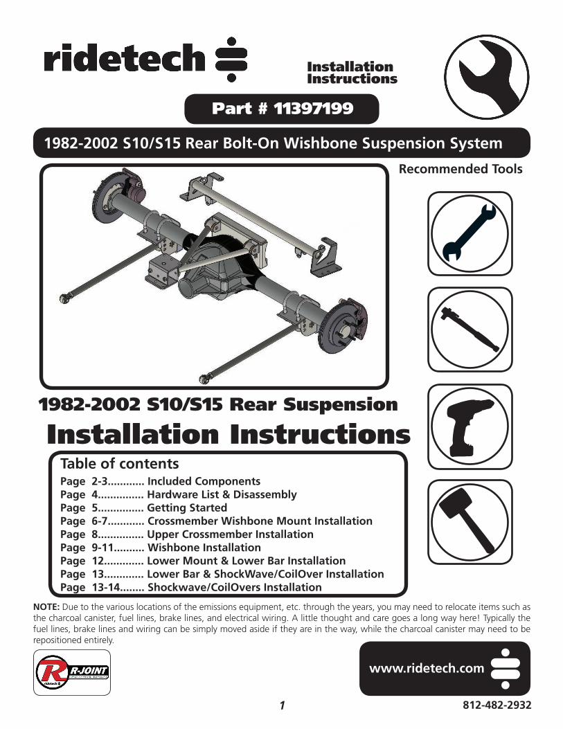
Major Components .....In the box
Item # Part # Description QTY
1 90002901 Lower Axle Bracket 22 90002902 Rear Upper ShockWave/CoilOver Mount Crossmember 13 90000387 Upper Wishbone Crossmember Bracket - Front Half 14 90002904 Upper Wishbone Crossmember Bracket with Mount - Rear Half 15 90002870 Rear Upper Wishbone 16 90002903 Rear Upper Control Arm Differential Mount 17 90002869 Lower Bars - Set to 26 1/4” 28 70013364 RH R-Joint Threaded Housing 29 90001617 5/8” Shock Stud 210 90001624 Aluminum Lower Shock Mount 211 90002067 Lower Shock Bearing Spacers 412 70013540 Narrow R-Joint Spacers (680” Long) - upper control arm and rear lower bar 613 70013768 Wide R-Joint Spacer (1.240” Long) - Lower Bars - front lower 414 70010759 Delrin Bushings - installed in upper control arm 415 90002895 Delrin Bushing Inner Sleeves - installed in upper control arm 216 99752004 3/4”-16 Jam Nut - Installed on Upper Control Arm 217 99566004 U-Bolt 9/16-18 x 3.13 x 5 w/2” Thread 4
R-Joint Components - (Installed in bar ends and front of wishbone)70013279 Retaining Ring 570013280 Wavo Wave Spring 570013275 R-Joint Center Ball 570013276 R-Joint Composite Center Ball Cage 5
New R-Joints will be quite stiff (75-90 in/lbs breakaway torque) until they “break in” after a few miles of use. After the break in period they will move much more freely. Because the composite bearing race contains self lubricating ingredients, no additional lubrication is needed or desired. Any additional lubrication will only serve to attract more dirt and debris to the R-Joint and actually shorten its life.

3 812-482-2932
InstallationInstructions
Major Components .....In the box
Install the Spacers by inserting the SMALL side of the SPACER into the Center Pivot Ball. Push them in until they bottom out and stop.
LOWER FRONT R-JOINT
ALL OTHER R-JOINTS
R-JOINT SPACERINSTALLATION
New R-Joints will be quite stiff (75-90 in/lbs breakaway torque) until they “break in” after a few miles of use. After the break in period they will move much more freely. Because the composite bearing race contains self lubricating ingredients, no additional lubrication is needed or desired. Any additional lubrication will only serve to attract more dirt and debris to the R-Joint and actually shorten its life.

4www.ridetech.com
InstallationInstructions
Hardware List .....In the box (Kit# 99010082)The Hardware Kit contains bags to help aid in selecting the correct hardware for the component being installed. The hardware list shows how the hardware is bagged.
DisassemblyCongratulations on your purchase of the Ridetech Rear Wishbone System. This system has been designed to give your truck excellent handling along with a lifetime of enjoyment. Some of the key features of this system: 3Link setup to replace the leaf spring and provide better control of the rear axle, upper wishbone to eliminate the side-to-side movement of the differential, R-joints for excellent wear and quiet operation, and the biggest feature of all, it allows the use of ShockWaves or CoilOvers.
Note: This system is designed for use with the Ridetech ShockWaves or CoilOvers. The factory shocks and springs or the factory sway bar will not fi t this 4Link.
QTY Part Number Description
WISHBONE FRONT CROSSMEMBER MOUNT6 99371004 3/8”-16 x 1 1/4” 12 99373003 3/8” Flat Washer6 99372002 3/8”-16 Nylok Nut4 99431001 7/16”-14 x 1”
UPPER CONTROL ARM MOUNTING1 99621004 5/8”x 3” SAE Gr. 8 Bolt3 99622006 5/8” SAE Nylok Jam Nut6 99623001 5/8” SAE Flat Washer2 99621005 5/8 x 3 1/2” Hex Bolt
LOWER 4LINK BARS2 99561012 9/16” x 4 1/2” SAE GR8 Bolt
4 99566003 9/16” SAE Flat Washer2 99562003 9/16” SAE Nylok Nut2 99621004 5/8”x 3” SAE Gr. 8 Bolt2 99622006 5/8” SAE Nylok Jam Nut4 99623001 5/8” SAE Flat Washer
BRAKE LINE JUNCTION BLOCK1 99311003 5/16”-18 x 1 1/2” Hex Bolt2 99313002 5/16” Flat Washer1 99312003 5/16”-18 Nylok Nut1 99000008 7/8” Insulated Clamp
QTY Part Number Description
UPPER WISHBONE DIFFERENTIAL MOUNT5 99315002 5/16-18 x 2 1/2” Gr. 8 Stud5 99313001 5/16” Flat Washer Gr. 85 99312002 5/16”-18 Nylok Nut Gr. 82 99312007 5/16”-18 Hex Nut1 90002263 Red Loctite
AXLE BRACKET TO AXLE8 99562010 9/16” SAE High Nut8 99566003 9/16” SAE Flat Washer
UPPER CROSSMEMBER10 99371004 3/8”-16 x 1 1/4” Hex Bolt20 99373003 3/8” Flat Washer10 99372002 3/8”-16 Nylok Nut
UPPER SHOCK MOUNTING2 99501050 1/2” x 2 1/2” USS Bolt Gr. 82 99502009 1/2” USS Nylok Nut Gr. 84 99503012 1/2” SAE Flat Washer Gr. 8
LOWER SHOCK MOUNT2 99501019 1/2”-13 x 1 1/4” Hex Bolt2 99501046 1/2”-13 x 1 3/4” Hex Bolt4 99502001 1/2”-13 Nylok Nut4 99503001 1/2” SAE Flat Washer

5 812-482-2932
InstallationInstructions
Getting Started...............1. Raise the truck to a safe and comfortable working height and support it by the frame. You will need to be able to raise and lower the differential. Use a jack under the rear differential so it can be raised and lowered as needed during the install.
2. This kit CAN be installed with the bed on.
3. Remove the leaf springs and shock absorbers. Refer to the factory service manual for proper disassembly procedures. If the Truck has the ZQ8 suspension package, the horizontal shock absorber & rear swaybar will need to be removed.
4.4. Remove the OEM bumpstop and bracket. A die grinder with a cutoff wheel works well for this. We use the cutoff wheel to cut the weld, taking care to not cut into the frame.
5. Grind the frame smooth after removing the bumpstop bracket. We recommend painting the area to prevent future rust.
5.

6www.ridetech.com
InstallationInstructions
Crossmember Wishbone Mount Installation6. If your truck came equipped with the emissions module mounted at the center of the gas tank crossmember, it will need to be relocated. The emissions control locations vary through the years. If the differential vent is mounted on top of the crossmember, it can be moved to the mounting hole for the emissions control module.
7. The Wishbone Crossmember Mount uses the Hardware Bag labeled “Wishbone Front Crossmember Mount”. Use Images 7 - 10 as a reference for installing the front Wishbone Mount. It sits on top of the gas tank crossmember with the PIN engaged into the CENTER HOLE of the crossmember. The Wishbone Mounting Point is to the REAR of the truck. In Image 7, the installer is lining up the pin with the locating hole in the crossmember.
8. The Front portion of the Wishbone Mount sits on top of the gas tank crossmember. 8.
6.
7.
FRONT
HOLE PIN
FRONT

7 812-482-2932
InstallationInstructions
10.
Wishbone Mount & Upper Crossmember Installation
9. The Rear half of the Wishbone Mount is installed against the bottom of the gas tank crossmember with the PIN ENGAGED IN THE HOLE. The Rear Half has the Wishbone Mount built into it. The 2 halves are bolted together using (6) 3/8”-16 x 1 1/4” Hex bolts, (6) 3/8”-16 Nylok Nuts, & (12) 3/8” SAE Flat Washers. Install a Flat Washer on each on the (6) Bolts. Hold the front half of the Wishbone Mount in place and insert a bolt/washer in each of the (6) holes. Install a 3/8” SAE Flat Washer and Nylok Nut on each of the Bolts. Torque to 30 ftlbs.
10. The Wishbone Mount has (2) 7/16”-14 Threaded Holes, front and rear. These are used if the Wishbone Mount fi ts the crossmember loosely. If it is loose, install a 7/16”-15 x 1” Bolt into each hole. Tighten the Bolts until the Mount is fi tting tightly on the crossmember.
11. Upper Crossmember Installation. The Upper Crossmember uses the Hardware Bag labeled “Upper Crossmember”. The Upper Crossmember locates off the OEM upper shock holes & the REAR Hole of the Bottom Flange. Remove the OEM u-nuts from the shock mounting holes, if equipped. Holding the Crossmember in position, bolt the locating tabs to the shock mounting holes using (1) 3/8”-16 x 1 1/4” Bolt, (2) 3/8” Flat Washers, & (1) 3/8”-16 Nylok Nut in each locating tab. Do the same for the Bottom Flange. Install the Hardware in both sides. Snug the hardware down, but do not tighten at this time.
11.
9.
7/16” BOLTS
LOCATORS
PASSENGER

8www.ridetech.com
InstallationInstructions
Upper Crossmember Installation
12. The NEW Crossmember has a Tab that rests against the top of the OEM shock crossmember. A hole will need to be drilled from the bottom side. The next 2 steps shop you how to mark the hole location from the bottom. Measure over 4” from the inside of the frame rail and put a couple marks above and below the tape measure tape.
13. Measure up 1 3/4” from the bottom edge of the OEM crossmember keeping the tape measure in line with the marks. Put a mark at the 1 3/4” measurement. If there isn’t a 4” mark, you will need one to mark center of the hole.
14. Drill the center of the marks with 3/8” Drill Bit. You will also need to drill the (2) holes in each Bottom Flange using the crossmember as a template. Use a drill with a 3/8” Drill Bit. Drill the (3) holes in the driver and passenger sides. Install a 3/8” Flat Washer on each of the (8) remaining 3/8”-16 x 1 1/4” bolts. Insert each of them into one of the drilled holes. Install a 3/8” Flat Washer and 3/8”-16 Nylok Nut on each bolt. Torque to 30 ftlbs. Also, Torque the (4) that were installed previously.
14.
12.
13.
4
DRILL WITH3/8” BIT
DRIVER
DRIVER

9 812-482-2932
InstallationInstructions
Wishbone Installation
15. Remove the TOP 5 Bolts from the differential cover. These are Circled in Image 15. Also remove the mounting bracket from the brake line distribution “T” and the emergency brake cable mounting bracket. IF THE DIFFERENTIAL COVER HAS A GASKET BETWEEN IT AND THE HOUSING, IT WILL NEED TO BE REMOVED AND SEALED WITH RTV SEALANT. Be sure to refi ll the differential with the correct gear oil before driving.
16. The Upper Wishbone front R-Joint is offset to the passenger side. Use Images 15 & 16 as a reference for assembling the Upper Wishbone to the Wishbone Axle Mount. Slip the wishbone into the Mount with the Front R-Joint offset to the passenger side.
17. The Wishbone Mounts are to the TOP of the Axle Mount. Insert the Wishbone into the Mount lining up the holes in the mount with the Inner Bushing Sleeves.
17.
DRIVERSIDE
SIDE VIEW
15.
16.
TOP VIEW
TOP

10www.ridetech.com
InstallationInstructions
Wishbone Installation
18. Using the Hardware Bag “Upper Wishbone Mounting”, install a 5/8” Flat Washer on each of (2) 5/8”-18 x 3 1/2” Bolts. Install each Bolt/Washer from the outside. With the bolts installed, install a 5/8” Flat Washer & 5/8”-18 Nylok Nut on each bolt. Tighten the Bolts/Nuts enough to eliminate any gaps.
19. The 5 OEM bolts that were removed from the top of the differential cover will be replaced with 5/16”-18 x 2 1/2” Studs. These Studs and the nuts used to install them, are supplied in the Hardware Bag labeled “Upper Wishbone Differential Mount”. Thread the (2) 5/16”-18 Hex Nuts on one of the studs. Using (2) wrenches, tighten the nuts against each other locking them together. Apply Red Loctite to the other end of the stud.
20. Thread the Stud into one of the 5 threaded holes in the axle housing. Torque the Stud to 25 ftlbs. Use 2 wrenches to unlock the nuts from each other and remove them from the stud. Repeat the process on the remaining 4 studs.
20.
19.
TOP VIEW
DRIVERSIDE
18.

11 812-482-2932
InstallationInstructions
23.
Wishbone Installation
21. Line the 5 holes in the Axle bracket with the 5 Studs that were just installed in the axle housing. Using the Hardware Bag “Upper Wishbone Differential Mount”, install a 5/16” Flat Washer, followed by a 5/16”-18 Nylok Nut on each of the (5) Studs. Torque the nuts to 25 ftlbs.
22. Using the Hardware Bag “Brake Line Junction Block”, install a 5/16” Flat Washer on a 5/16”-18 x 1 /2” Bolts. Insert the bolt/washer through the junction block and mounting hole in the differential bracket. Install the Insulated Clamp on the emergency brake cable, it will attach to the 5/16” bolt on the bottom side of the axle mount. Slip the mounting hole of the clamp onto the threads of the 5/16” bolt. Install a 5/16” Flat Washer & 5/16”-18 Nylok Nut on the threads of the bolt. The brake lines will need to be tweaked to get the distribution block in position. Torque the bolts to 25 ftlbs.
23. Insert a Narrow R-Joint Spacer (.680”) into each side of the front R-joint of the Wishbone. Using the Hardware Bag “Upper Wishbone Mounting”, install a 5/8” Flat Washer on a 5/8”-18 x 3” Bolt. Line up the R-Joint with the Front Wishbone Mount. Insert the bolt/washer in the lined up r-joint/mount. With the bolt installed, install a 5/8” Flat Washer & 5/8”-18 Nylok Nut on the bolt. Tighten the Bolts/Nuts enough to eliminate any gaps.
22.
21.
INSULATEDCLAMP

12www.ridetech.com
InstallationInstructions
Lower Mount & Lower Bar Installation24. The Axle Mounts are the same for driver and passenger sides. Install the supplied 9/16” U-bolts on each side of the OEM leaf spring pads. Slide an Axle Mount on the U-bolts with the center pin inserted into the leaf spring pad. The hardware bag is labeled “Lower Axle Bracket to Axle”. Hold the mount in place and install a 9/16” Flat Washer and 9/16” High Nut on the threads of the u-bolts sticking through the axle mount. Tighten the nuts evenly in a crisscross fashion making sure the center pin is engaged into the leaf spring pad. Torque the nuts in a crisscross fashion to 60 ftlbs. Repeat on the other side.
25. The Hardware Bag for the Lower Shock Mount is labeled “Lower Shock Mounting”. The Lower Shock Mount attaches with (1) 1/2”-13 x 1 1/4” Hex Bolt, (1) 1/3”-13 x 1 3/4” Hex Bolt, & (2) 1/2” Flat Washers, & (2) 1/2”-13 Nylok Nuts. The Lower Mount gets attached to the TOP 2 holes of the Axle Mount. Insert the Bolts through the Aluminum Shock Mount with the 1 1/4” long bolt in the top hole, 1 3/4” in the bottom hole. Insert the bolts through the TOP 2 holes of the Axle Mount and install the Flat Washers & Nylok Nuts on the Threads sticking through. Repeat on both sides and torque the Bolts/Nuts to 75 ftlbs. Install a 5/8” Flat Washer onto the 5/8”-18 threads of the shock stud. Apply Red Loctite to the 5/8” threads of the stud. Thread the Shock Stud into the threaded hole of the Lower Mount. Repeat on both sides and torque the Shock Stud to 65-75 ftlbs.
26. The hardware bag for the lower bars is labeled “Lower Link Bars”. Insert the long R-Joint Spacers (1.240” long) into the front of the lower bar with the small OD inserted into the R-joint. Insert the Front Lower Bar R-Joint into the Front Leaf Spring Mount. Line the through hole of the R-Joint with the holes of the leaf spring mount. Install a 9/16” Flat Washer on to a 9/16”-18 x 4 1/2” Hex Bolt, insert into the lined up holes. Install a 9/16” Flat Washer followed by a 9/16”-18 Thin Jam Nylok Nut. Repeat on both sides and tighten the Bolts/Nuts enough to eliminate any gaps.
26.
24.
25.
13 812-482-2932
InstallationInstructions
28.
27.
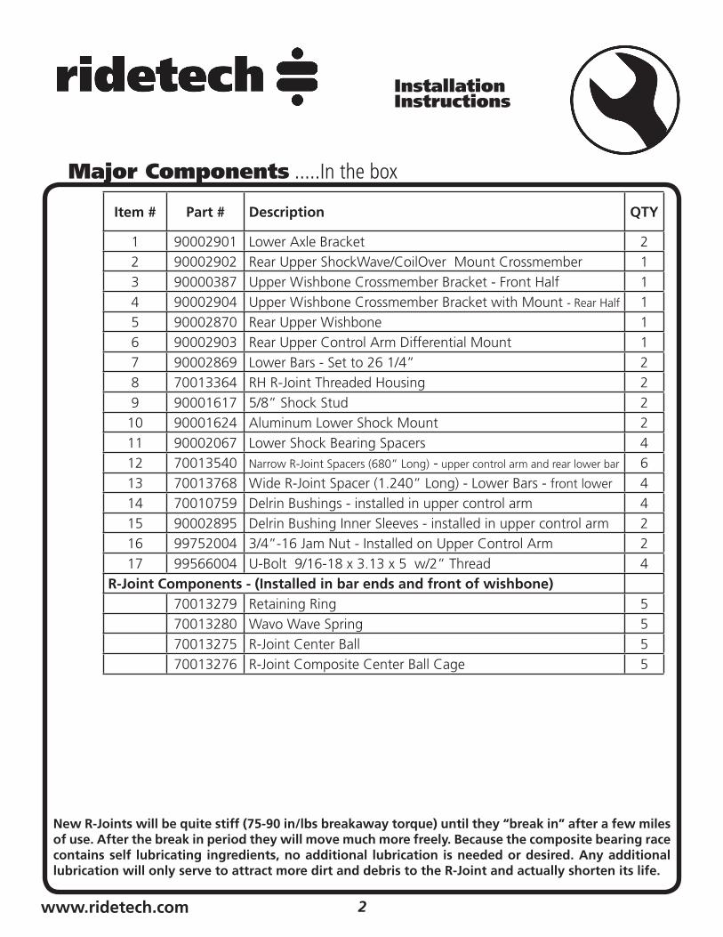
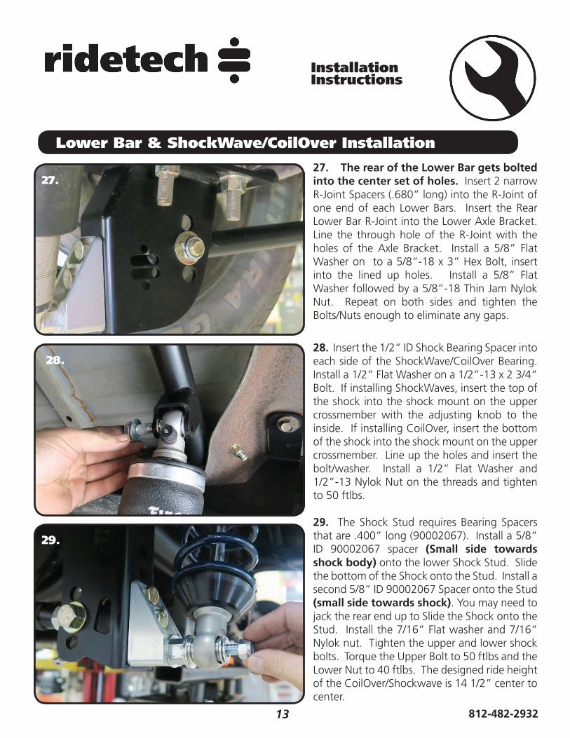
Lower Bar & ShockWave/CoilOver Installation
27. The rear of the Lower Bar gets bolted into the center set of holes. Insert 2 narrow R-Joint Spacers (.680” long) into the R-Joint of one end of each Lower Bars. Insert the Rear Lower Bar R-Joint into the Lower Axle Bracket. Line the through hole of the R-Joint with the holes of the Axle Bracket. Install a 5/8” Flat Washer on to a 5/8”-18 x 3” Hex Bolt, insert into the lined up holes. Install a 5/8” Flat Washer followed by a 5/8”-18 Thin Jam Nylok Nut. Repeat on both sides and tighten the Bolts/Nuts enough to eliminate any gaps.
28. Insert the 1/2” ID Shock Bearing Spacer into each side of the ShockWave/CoilOver Bearing. Install a 1/2” Flat Washer on a 1/2”-13 x 2 3/4” Bolt. If installing ShockWaves, insert the top of the shock into the shock mount on the upper crossmember with the adjusting knob to the inside. If installing CoilOver, insert the bottom of the shock into the shock mount on the upper crossmember. Line up the holes and insert the bolt/washer. Install a 1/2” Flat Washer and 1/2”-13 Nylok Nut on the threads and tighten to 50 ftlbs.
29. The Shock Stud requires Bearing Spacers that are .400” long (90002067). Install a 5/8” ID 90002067 spacer (Small side towards shock body) onto the lower Shock Stud. Slide the bottom of the Shock onto the Stud. Install a second 5/8” ID 90002067 Spacer onto the Stud (small side towards shock). You may need to jack the rear end up to Slide the Shock onto the Stud. Install the 7/16” Flat washer and 7/16” Nylok nut. Tighten the upper and lower shock bolts. Torque the Upper Bolt to 50 ftlbs and the Lower Nut to 40 ftlbs. The designed ride height of the CoilOver/Shockwave is 14 1/2” center to center.
29.

14www.ridetech.com
InstallationInstructions
30.
ShockWave/CoilOver Installation
30. This particular truck had the emissions canister mounted right behind the gas tank. We had to trim the rear corner off for clearance of the new lowered suspension.
31. Image 31 illustrates were we moved the differential vent that was on top of the crossmember. It will bolt in the hole that the emissions modules was bolt into using the OEM hardware.
32. For Trucks with the Emissions Control on the gas tank crossmember, we attached it to the end of the Charcoal Canister.
33. Setting Ride Height - The Shock mount to mount dimension should be 14 1/2”. For trucks with ShockWaves, it’s a matter of adjusting the air pressure to obtain the ride height. CoilOver trucks will require adjusting the coilspring spanner nut on the shock to obtain the correct ride height.
31.
32.