Embed Size (px)
Citation preview

13.42 Lecture:Vortex Induced Vibrations
Prof. A. H. Techet21 April 2005
Offshore Platform
Courtesy of U.S. DOE.
Fixed Rigs Tension Leg Platforms
Figures removed for copyright reasons.
Spar Platforms
Figures removed for copyright reasons.
Genesis Spar Platform
Photos of Genesis Spar Oil Platform removed for copyright reasons. Please See: http://www.offshore-technology.com/projects/genesis/.
VIV Catastrophe
If neglected in design, vortex induced vibrations can prove catastrophic to structures, as they did in the case of the Tacoma
Narrows Bridge in 1940.
Image removed for copyright reasons.
John Hancock Building “I n another city, the John Hancock tower wouldn't be anything special -- just another reflective glass box in the crowd. But because of the way Boston and the rest of New England has grown up architecturally, this "70's modern" building stands out from the rest. Instead of being colonial, it breaks new ground. Instead of being quaint, it soars and imposes itself on the skyline. And Instead of being white like so many buildings in the region, this one defies the local conventional wisdom and goes for black. For these reasons and more the people of Boston have fallen in love with the 790-foot monster looming as the tallest building in New England at the time of its completion. In the mid-1990's, The Boston Globe polled local architects who rated it the city's third best architectural structure. Much like Boston's well-loved baseball team, the building has had a rough past, but still perseveres, coming back stronger to win the hearts of its fans. The trouble began early on. During construction of the foundation the sides of the pit collapsed, nearly sucking Trinity Church into the hole. Then in late January, 1973 construction was still underway when a winter storm rolled into town and a 500-pound window leapt from the tower and smashed itself to bits on the ground below. Another followed. Then another. Within a few weeks, more than 65 of the building's 10,344 panes of glass committed suicide, their crystalline essence piling up in a roped-off area surrounding the building. The people of Bean Town have always been willing to kick a brother when he's down, and started calling the tower the Plywood Palace because of the black-painted pieces of wood covering more than an acre of its façade. Some people thought the building was swaying too much in the wind, and causing the windows to pop out. Some thought the foundation had shifted and it was putting stress of the structural geometry. It turns out the culprit was nothing more than the lead solder running along the window frame. It was too stiff to deal with the kind of vibrations that happen every day in thousands of office buildings around the world. So when John Hancock Tower swayed with the wind, or sighed with the temperature, the windows didn't and eventually cracked and plummeted to Earth. It cost $7,000,000.00 to replace all of those panes of glass. The good news is, you can own a genuine piece of the skyscraper. According to the Globe, the undamaged sheets were sold off for use as tabletops, so start combing those garage sales. For any other skyscraper, the hardship would end there. But the Hancock building continued to suffer indignities. The last, and most ominous, was revealed by Bruno Thurlimann, a Swiss engineer who determined that the building's natural sway period was dangerously close to the period of its torsion. The result was that instead of swaying back-and-forth like a in the wind like a metronome, it bent in the middle, like a cobra. The solution was putting a pair of 300-ton tuned mass dampeners on the 58-th floor. The same engineer also determined that while the $3,000,000.00 mass dampeners would keep the building from twisting itself apart, the force of the wind could still knock it over. So 1,500 tons of steel braces were used to stiffen the tower and the Hancock building's final architectural indignity was surmounted.”
Reprinted from http://www.glasssteelandstone.com/BuildingDetail/399.php
Image removed for copyright reasons.
Courtesy of Artefaqs Corporation. Used with permission.Source: Glass Steel and Stone, http://www.glasssteelandstone.com.

Classical Vortex Shedding
Von Karman Vortex Street
l h
Alternately shed opposite signed vortices
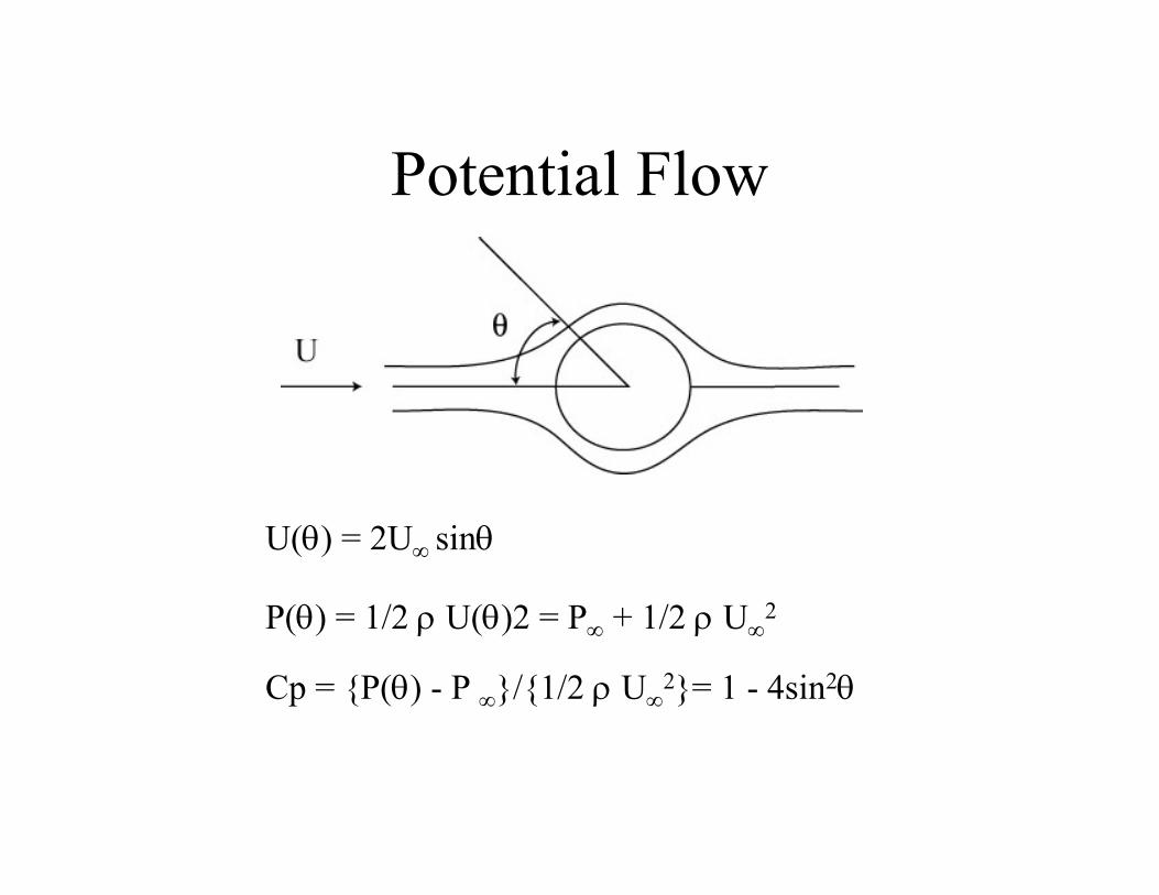
Potential Flow
U(θ) = 2U∞ sinθ
2P(θ) = 1/2 ρ U(θ)2 = P∞ + 1/2 ρ U∞
Cp = {P(θ) - P ∞}/{1/2 ρ U∞ 2}= 1 - 4sin2θ
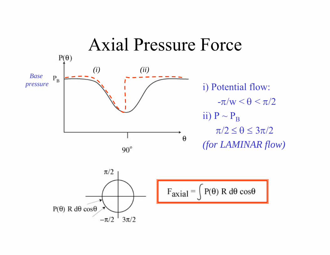
Axial Pressure Force
i) Potential flow: -π/w < θ < π/2
ii) P ~ PB
π/2 ≤ θ ≤ 3π/2 (for LAMINAR flow)
Base pressure
(i) (ii)
Wake Instability
Figure removed for copyright reasons.

Shear layer instability causes vortex roll-up
• Flow speed outside wake is much higher than inside
• Vorticity gathers at downcrossing points in upper layer
• Vorticity gathers at upcrossings in lower layer
• Induced velocities (due to vortices) causes this perturbation to amplify

Reynolds Number Dependency
Rd < 5
5-15 < Rd < 40
40 < Rd < 150
150 < Rd < 300Transition to turbulence
300 < Rd < 3*105
3*105 < Rd < 3.5*106
3.5*106 < Rd
Figure by MIT OCW.
Regime of Unseparated Flow
Regimes of fluid flow across smooth circular cylinders (Lienhard, 1966).
A Fixed Pair of Foppl Vortices in Wake
Two Regimes in which Vortex Street is Laminar
Transition Range to Turbulence in Vortex
Vortex Street is Fully Turbulent
Re-establishment of Turbulent Vortex Street
Laminar Boundary Layer has Undergone Turbulent Transition and Wake is Narrower and Disorganized

Vortex shedding dictated by the Strouhal number
St=fsd/Ufs is the shedding frequency, d is diameter and U inflow speed
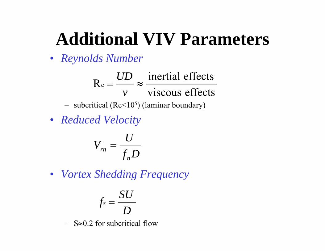
Additional VIV Parameters• Reynolds Number
UD effects inertial Re = ≈ v effects viscous
– subcritical (Re<105) (laminar boundary)
• Reduced Velocity UV = rn D fn
• Vortex Shedding Frequency
SUfs = D
– S≈0.2 for subcritical flow
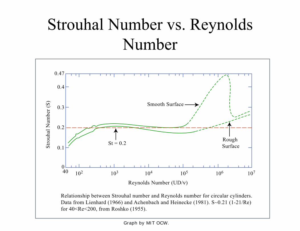
Strouhal Number vs. Reynolds Number
Graph by MIT OCW.
10240
Stro
uhal
Num
ber (
S)
0.1
0
Relationship between Strouhal number and Reynolds number for circular cylinders. Data from Lienhard (1966) and Achenbach and Heinecke (1981). S~0.21 (1-21/Re)for 40<Re<200, from Roshko (1955).
Reynolds Number (UD/ν)
0.2
0.3
0.4
0.47
103 104
Smooth Surface
St = 0.2Rough Surface
105 106 107
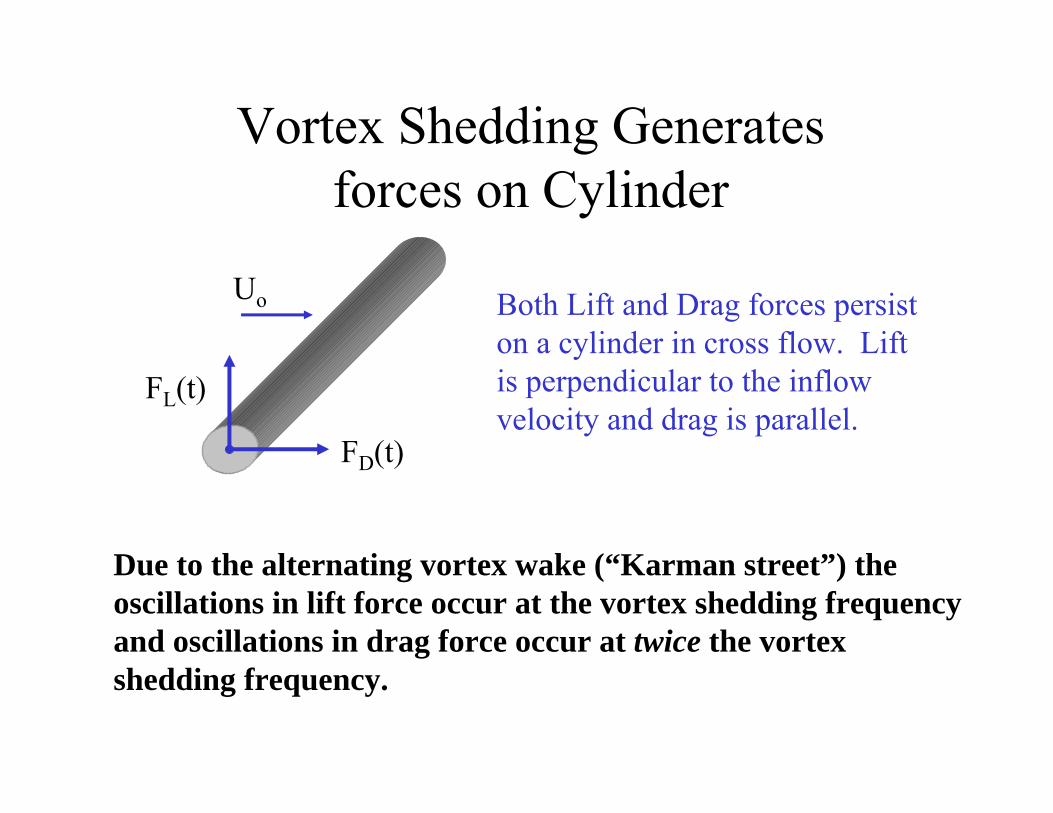
Vortex Shedding Generates forces on Cylinder
FD(t)
FL(t)
Uo Both Lift and Drag forces persist on a cylinder in cross flow. Lift is perpendicular to the inflow velocity and drag is parallel.
Due to the alternating vortex wake (“Karman street”) the oscillations in lift force occur at the vortex shedding frequency and oscillations in drag force occur at twice the vortex shedding frequency.
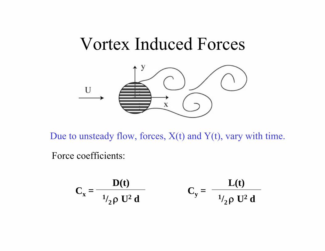
Vortex Induced Forces
Due to unsteady flow, forces, X(t) and Y(t), vary with time.
Force coefficients:
D(t)Cx =
1/2 ρ U2 d L(t)
Cy = 1/2 ρ U2 d
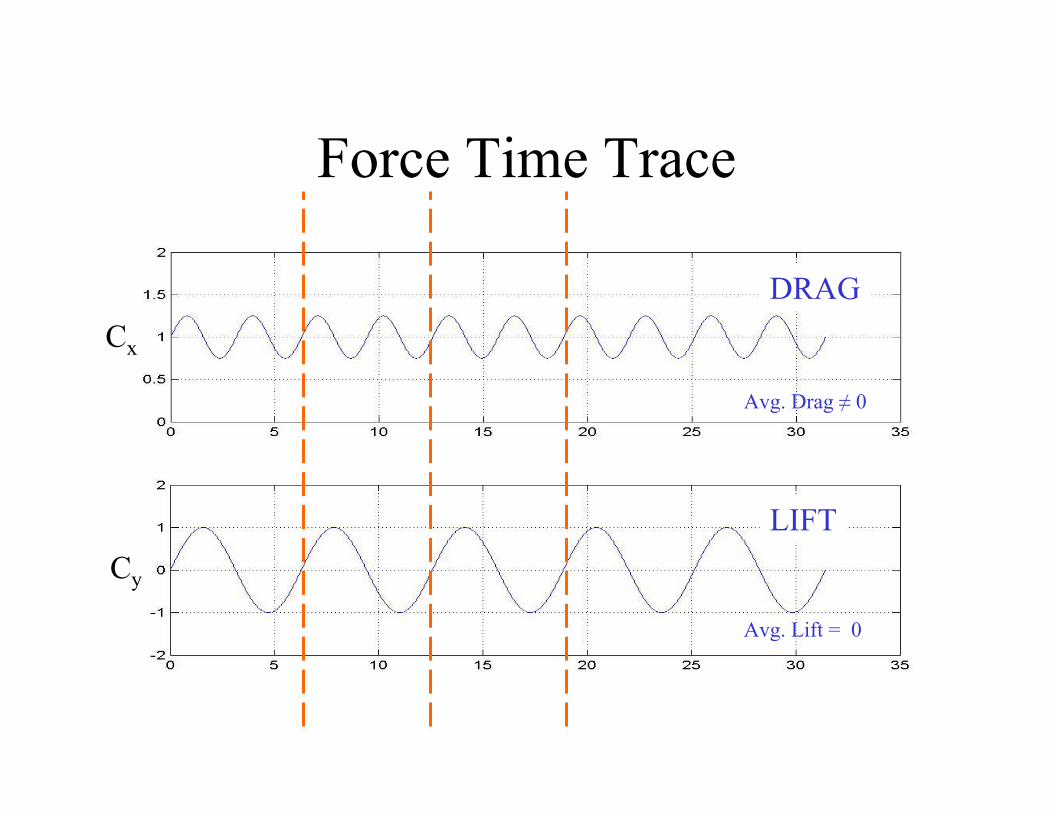
Force Time Trace
Cx
Cy
DRAG
LIFT
Avg. Drag ≠ 0
0Avg. Lift =
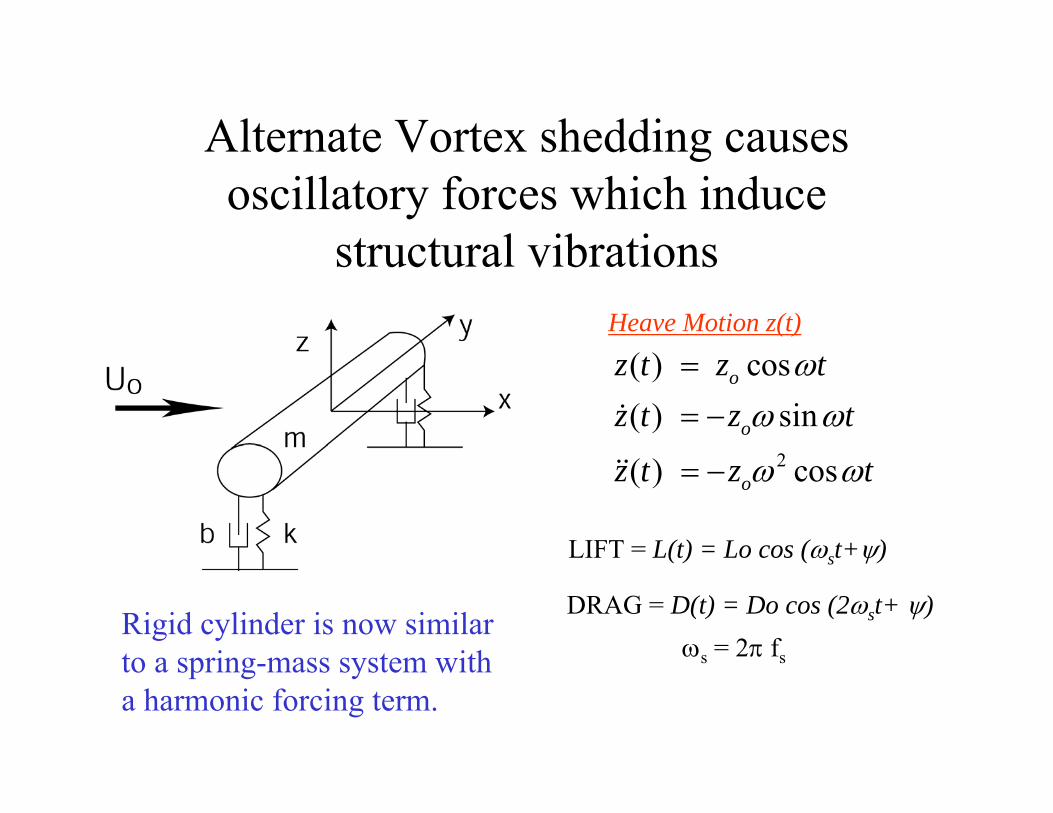
Alternate Vortex shedding causes oscillatory forces which induce
structural vibrationsHeave Motion z(t)
z t( ) = z cos ωto
&( ) = −z ω sin ωtz t o
&&( ) = −z ω cos ωtz t 2 o
LIFT = L(t) = Lo cos (ω t+ψ)s
Rigid cylinder is now similar DRAG = D(t) = Do cos (2ω t+ ψ)s
to a spring-mass system with ωs = 2π fs
a harmonic forcing term.
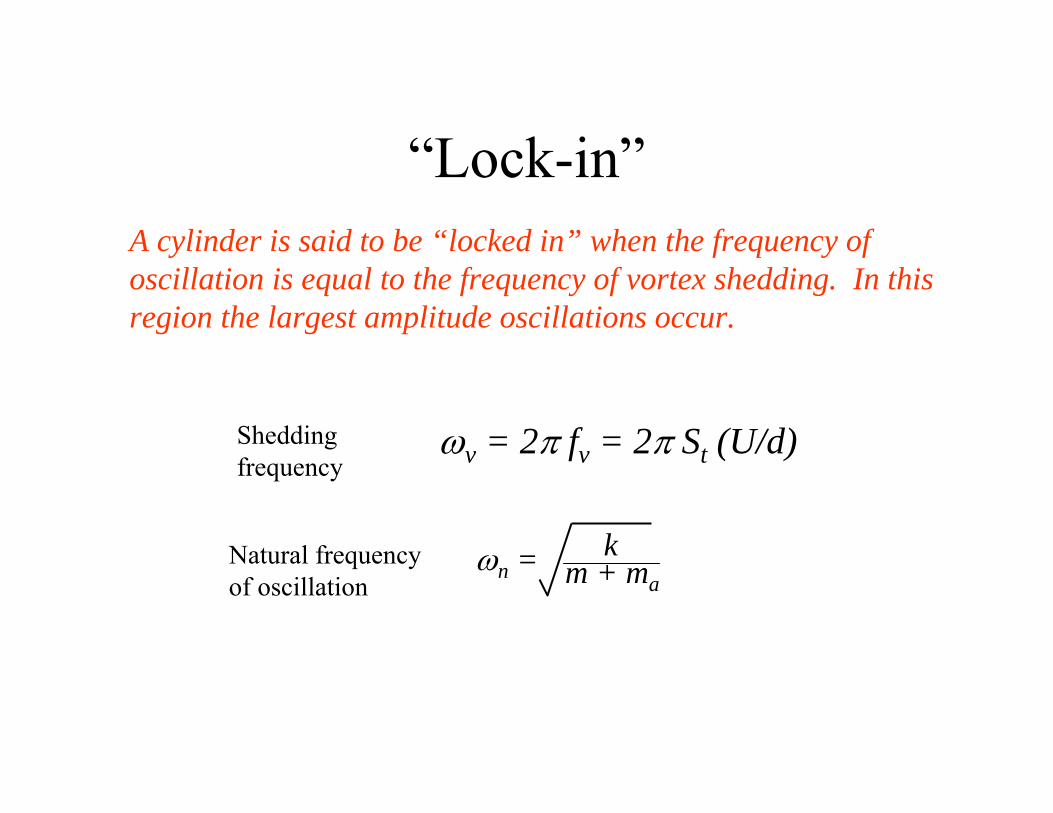
“Lock-in”A cylinder is said to be “locked in” when the frequency of oscillation is equal to the frequency of vortex shedding. In this region the largest amplitude oscillations occur.
Shedding ω = 2π fv = 2π St (U/d)frequency v
kNatural frequency ωn = m + maof oscillation
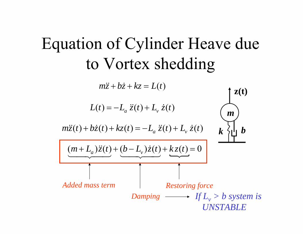
Equation of Cylinder Heave due to Vortex shedding
mz&& + bz& + kz = L t ( )
m
z(t)
L t &&( ) + L z t ( ) = −L z t &( )a v
mz t &( ) + kz t && ( ) + L z t &&( ) + bz t ( ) = − La z t v &( ) k b
(m L )&&( ) + (b − L )z t ( ) = 0+ z t &( ) + k z t a v14243 14243 {
Added mass term Restoring force Damping If Lv > b system is
UNSTABLE
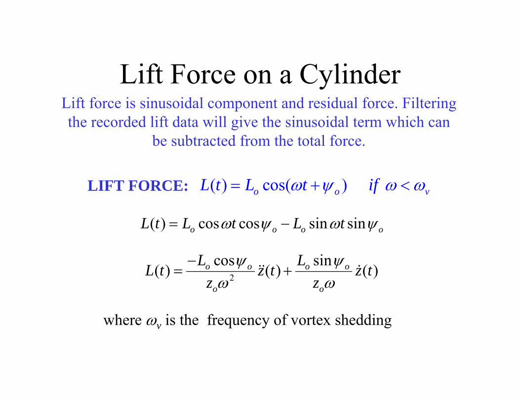
Lift Force on a CylinderLift force is sinusoidal component and residual force. Filteringthe recorded lift data will give the sinusoidal term which can
be subtracted from the total force.
(LIFT FORCE: L t) = L cos( ωt +ψ ) if ω < ωo o v
L t t sin ( ) = L cos ωt cos ψ − L sin ω ψ o o o o
−L cos ψ L sin ψo oL t 2 z t o &( )( ) = o &&( ) + z t z ω z ωo o
where ω is the frequency of vortex sheddingv
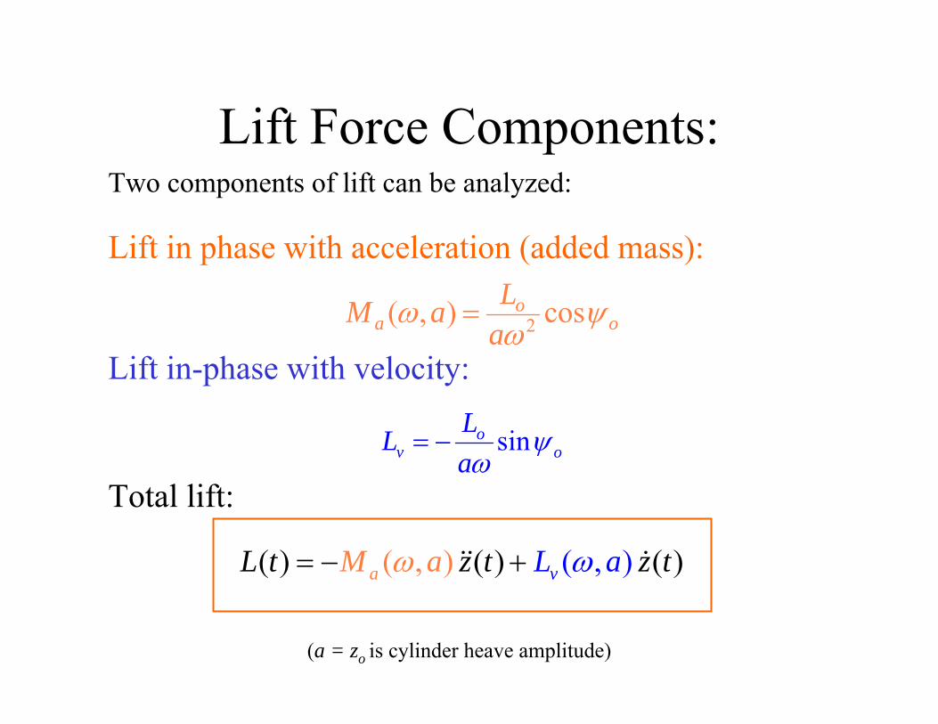
Lift Force Components:Two components of lift can be analyzed:
Lift in phase with acceleration (added mass):
ω a) = Lo cos ψ oMa ( , 2aω Lift in-phase with velocity:
LoL = − sinψv oaω Total lift:
L t ω a) &&(( ) = −M ( , z t ) + L (ω, a) z&(t)a v
(a = zo is cylinder heave amplitude)
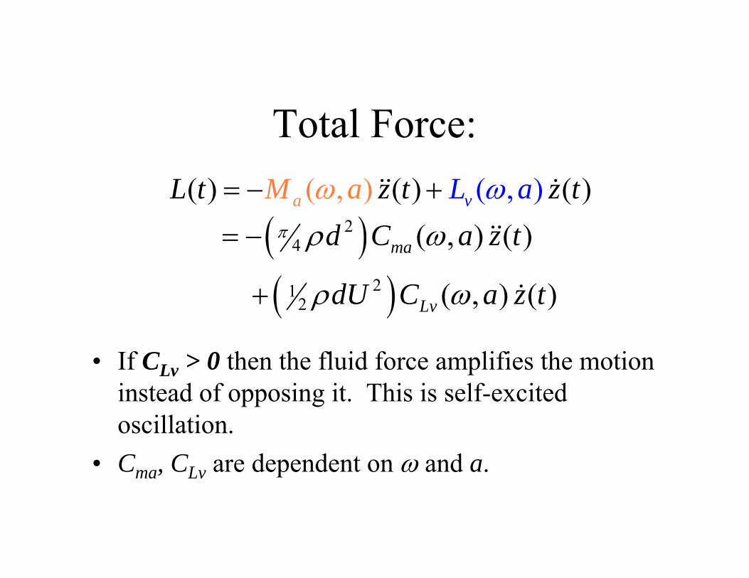
Total Force:L t ω a) &&(( ) = −M ( , z t ) + L (ω, a) z&(t)a v
2 ) ω a) &&(= −( 4 π ρd C ( , z t )ma
1 2
2ρdU )CLv ( , &(ω a) z t )+(• If CLv > 0 then the fluid force amplifies the motion
instead of opposing it. This is self-excited oscillation.
• Cma, CLv are dependent on ω and a.
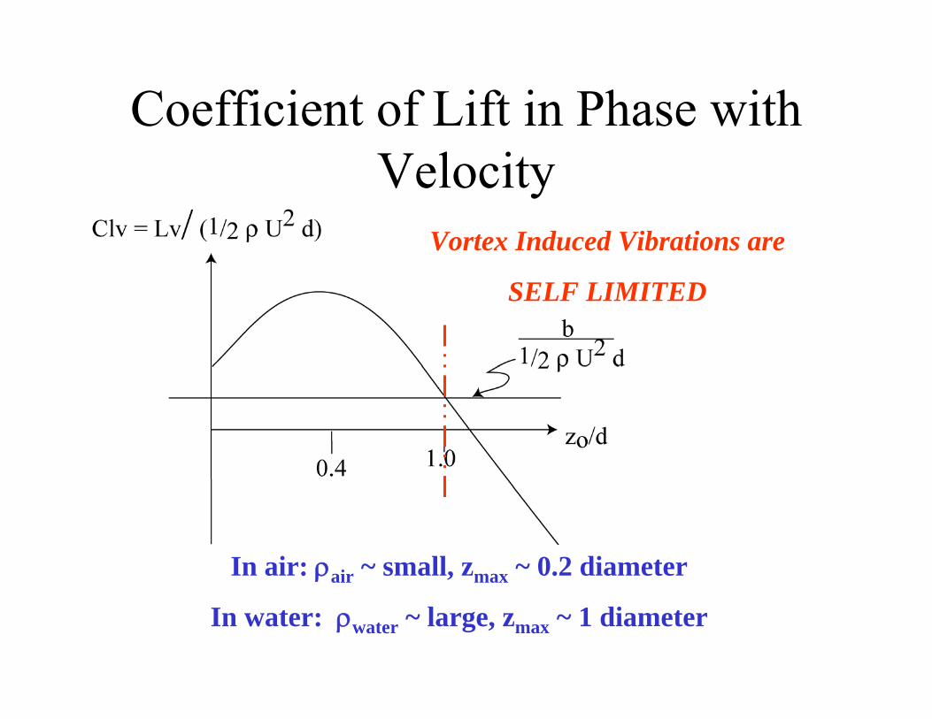
Coefficient of Lift in Phase with Velocity
Vortex Induced Vibrations are
SELF LIMITED
In air: ρair ~ small, zmax ~ 0.2 diameter
In water: ρwater ~ large, zmax ~ 1 diameter
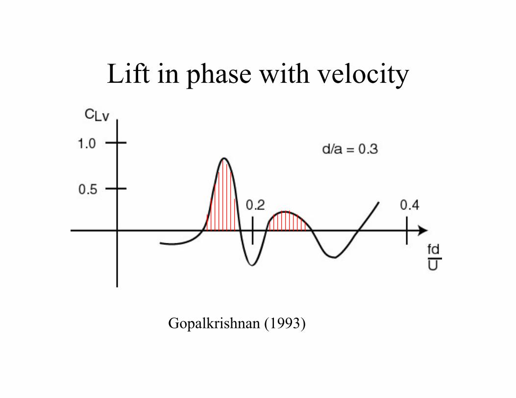
Lift in phase with velocity
Gopalkrishnan (1993)
=
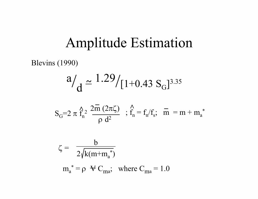
Amplitude EstimationBlevins (1990)
a/ 3.35~ 1.29/[1+0.43 SG]d _ _^ 2 2m (2πζ) ; f̂
n = fn/fs; m = m + ma*SG=2 π fn ρ d2
bζ =
2 k(m+ma *)
*ma = ρ V Cma; where Cma = 1.0
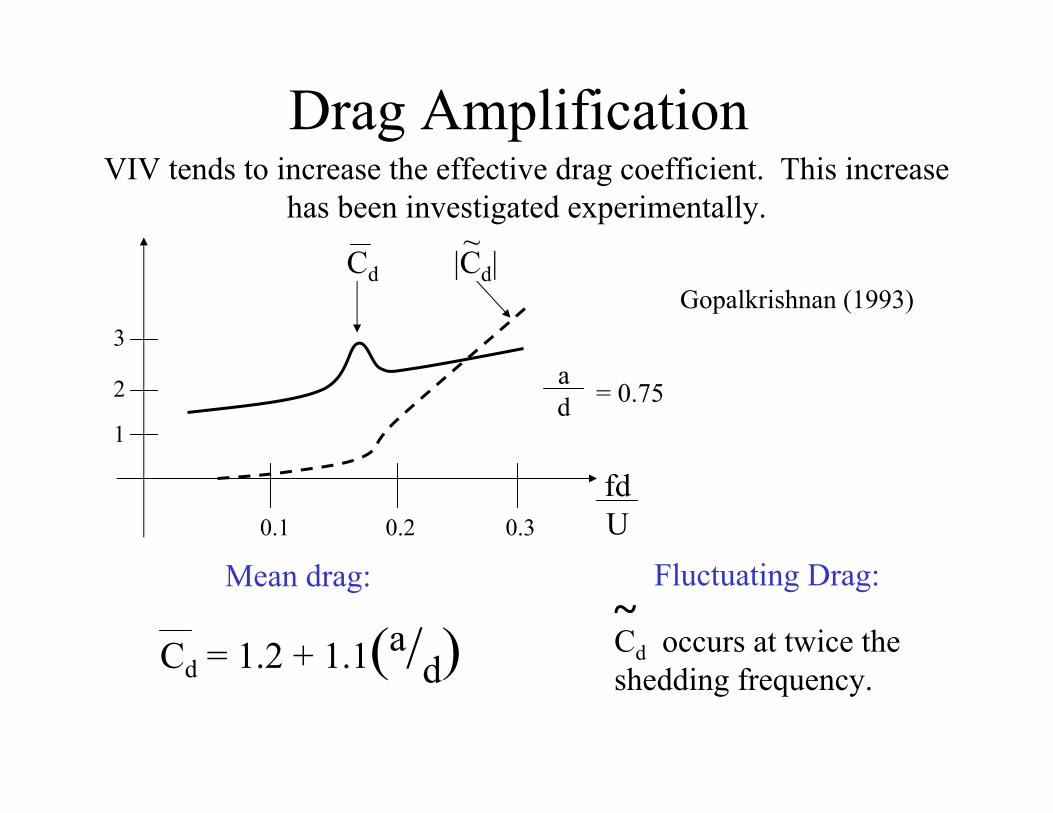
Drag AmplificationVIV tends to increase the effective drag coefficient. This increase
has been investigated experimentally.
3
2
1
Cd |Cd|
0.1 0.2 0.3
ad
~
Gopalkrishnan (1993)
= 0.75
fdU
Mean drag: Fluctuating Drag: ~
a Cd occurs at twice theCd = 1.2 + 1.1( /d) shedding frequency.
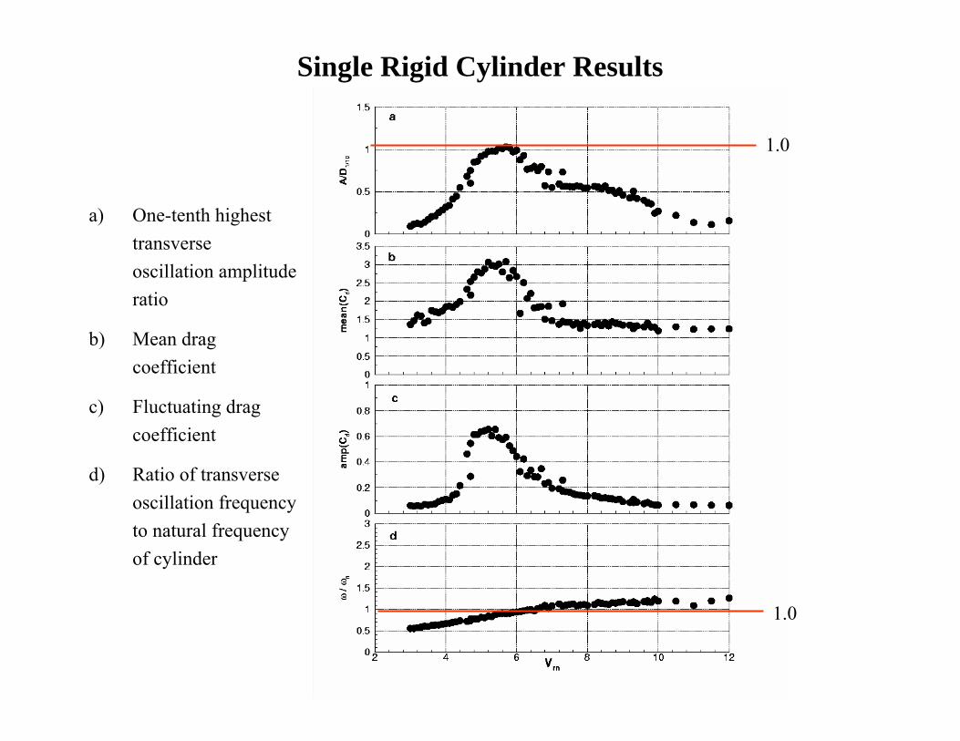
Single Rigid Cylinder Results
a) One-tenth highest transverse oscillation amplitude ratio
b) Mean drag coefficient
c) Fluctuating drag coefficient
d) Ratio of transverse oscillation frequency to natural frequency of cylinder
1.0
1.0
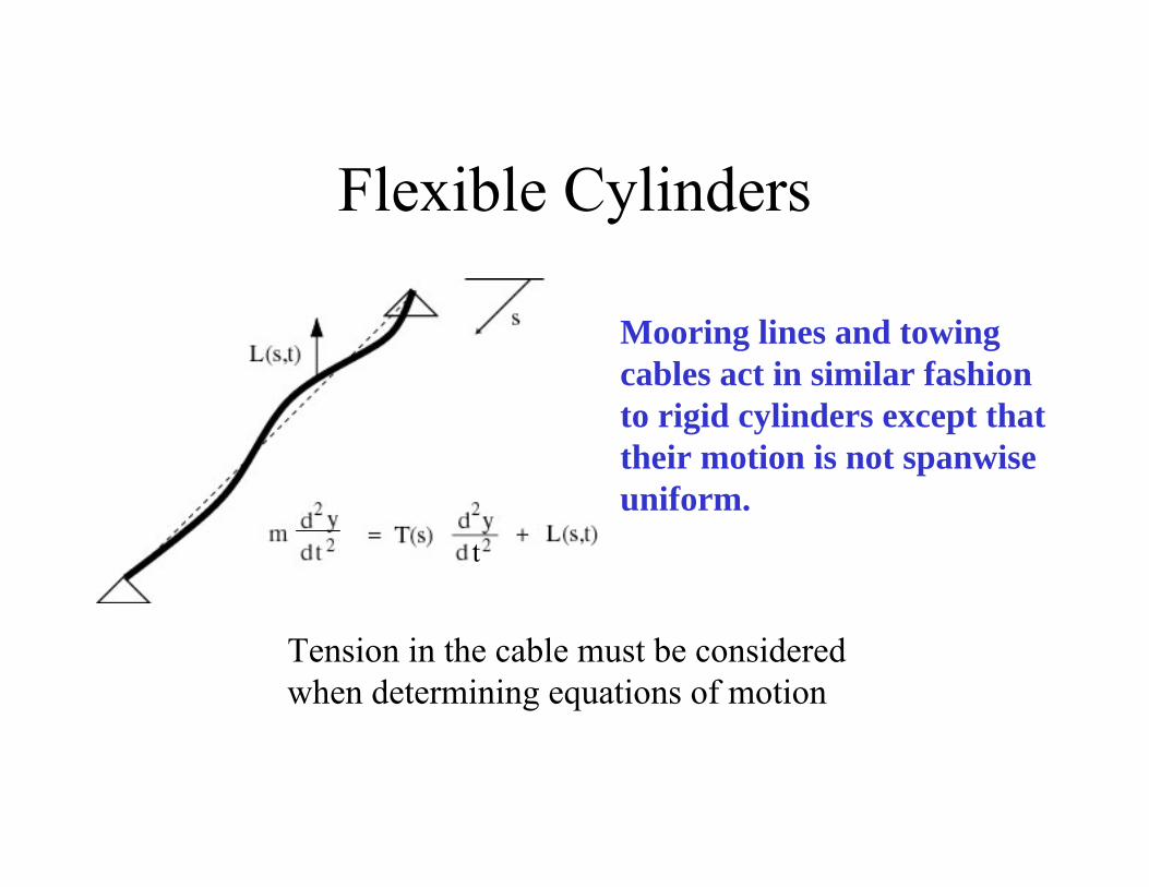
Flexible Cylinders
t
Mooring lines and towing cables act in similar fashion to rigid cylinders except that their motion is not spanwise uniform.
Tension in the cable must be considered when determining equations of motion
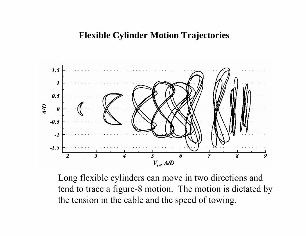
Flexible Cylinder Motion Trajectories
Long flexible cylinders can move in two directions and tend to trace a figure-8 motion. The motion is dictated by the tension in the cable and the speed of towing.