Embed Size (px)
Citation preview
Evaluation Methodology for Rolling Shear in Cross Laminated Timber (CLT)
Qinyi Zhou
Faculty of Forestry and Environment ManagementUniversity of New Brunswick
Vancouver, Canada, 2ND May 2012
(NEWBuildS T1-1-C1)

Content
Objectives
Methods
Preliminary results
Future work
Objectives
Determine the rolling shear properties of CLT Examine testing methodology Testing specimens Testing methods ASTM D198 Bending test ASTM D1037 Two‐plate shear test
verify experimental results through numerical analysis
Overall, recommend a more appropriate method
Methods
Clear black spruce boards (20oC/ 65%RH, 12% MC)
Steel strips (Cold roll 16‐gauge )
Adhesives
polyurethane for edge gluing and epoxy for face gluing
Materials

Specimens preparation
6 replicates per growth ring orientation
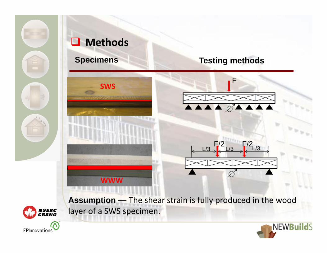
Specimens Testing methods
F
F/2 F/2L/3 L/3 L/3
SWS
WWW
Assumption — The shear strain is fully produced in the wood layer of a SWS specimen.
Methods
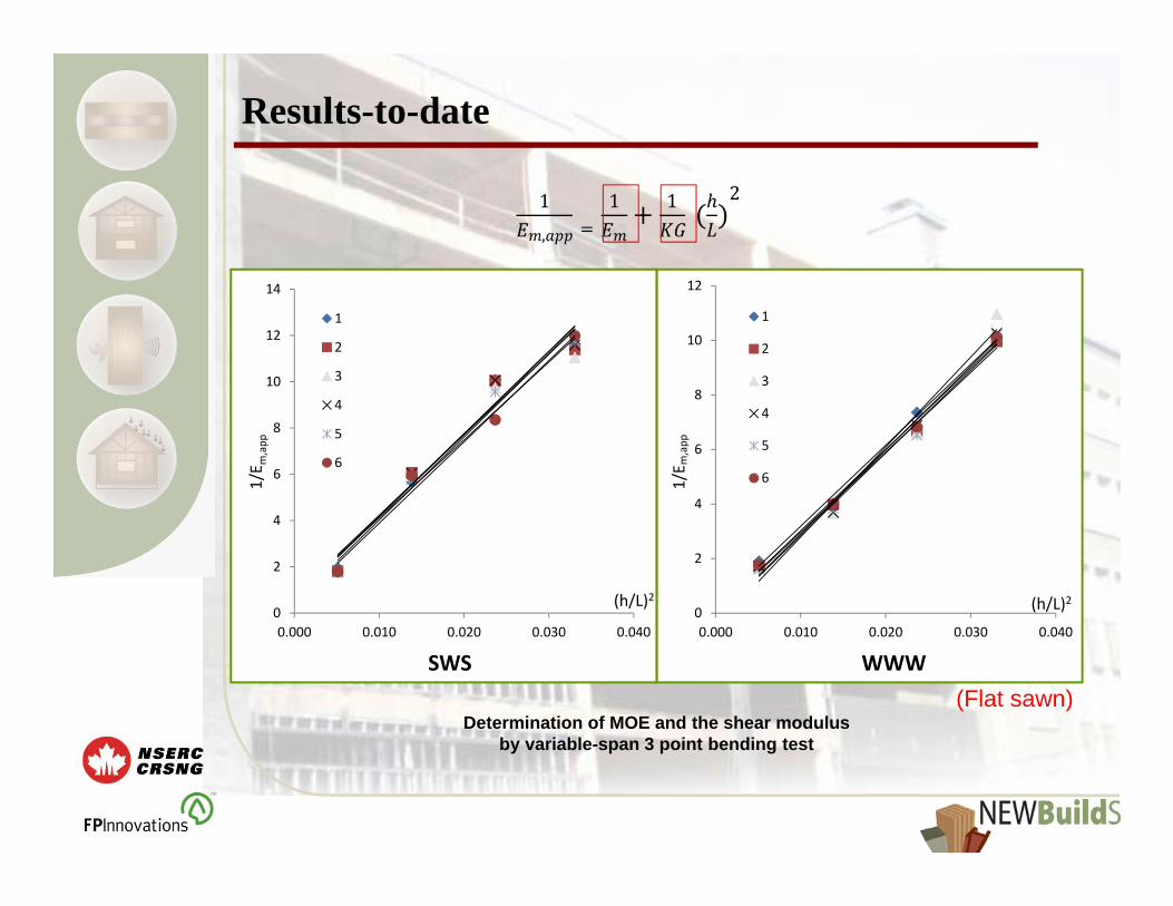
Determination of MOE and the shear modulus by variable-span 3 point bending test
Results-to-date
SWS WWW
0
2
4
6
8
10
12
0.000 0.010 0.020 0.030 0.040
1
2
3
4
5
6
(h/L)2
1/E m
,app
0
2
4
6
8
10
12
14
0.000 0.010 0.020 0.030 0.040
1
2
3
4
5
6
(Flat sawn)
(h/L)2
1/E m
,app

Results-to-date
SWS WWW
0
1
2
3
4
5
6
7
8
9
10
0.000 0.005 0.010 0.015 0.020 0.025
1
2
3
4
5
0
2
4
6
8
10
12
0.000 0.010 0.020 0.030 0.040
1
2
3
4
5
6
(h/L)2
1/E m
,app
Determination of MOE and the shear modulus by variable-span 4 point bending test
(Flat sawn)
(h/L)2
1/E m
,app

Results to-date
Apparent shear modulus (MPa)
Specimens SWS WWW
Testing method
3‐pt 4‐pt 3‐pt 4‐pt
G (MPa) 23.73 28.17 27.37 29.26COV(%) 2.4 1.3 4.2 0.5
Calculate the true rolling shear modulus fromSWS data using Shear Analogy method
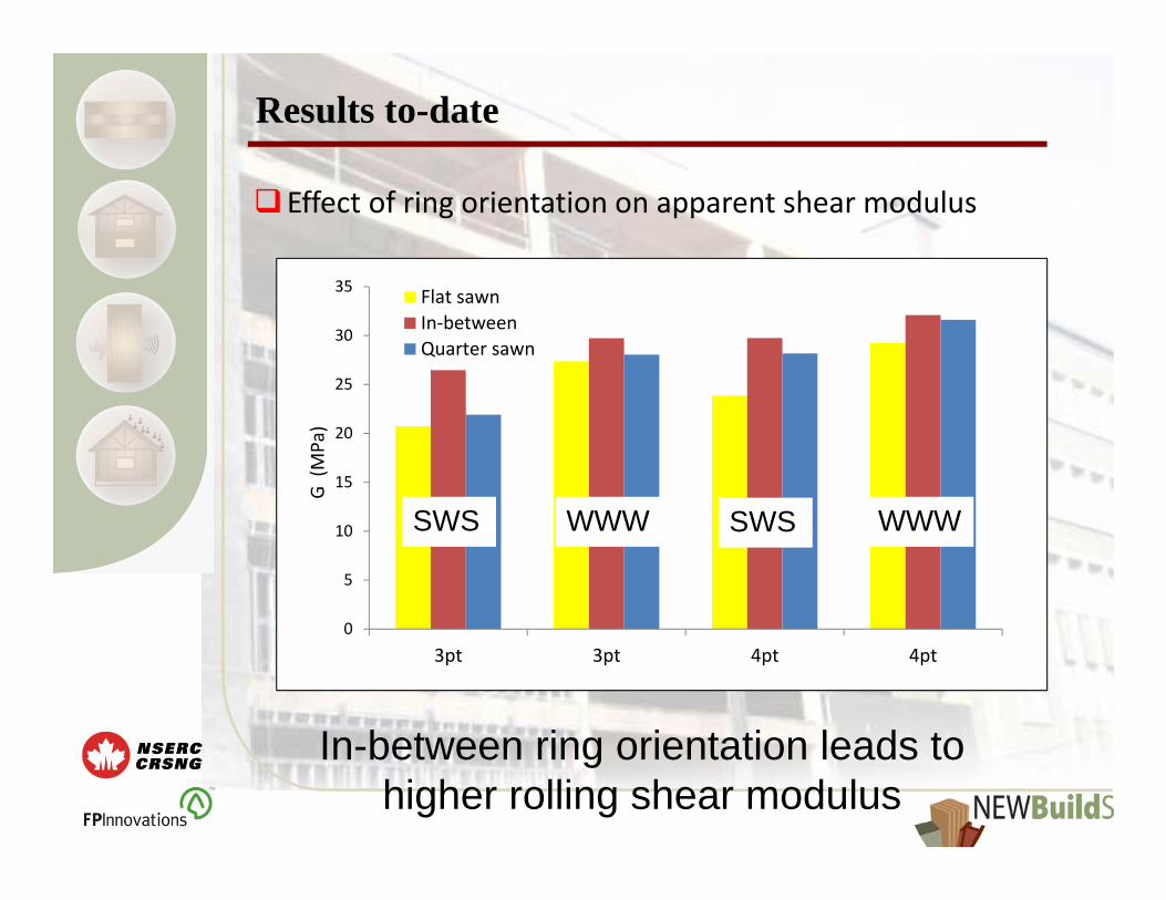
Results to-date
Effect of ring orientation on apparent shear modulus
0
5
10
15
20
25
30
35
3pt 3pt 4pt 4pt
Flat sawnIn‐betweenQuarter sawn
G (MPa)
SWS WWW SWS WWW
In-between ring orientation leads to higher rolling shear modulus

Future Work
2‐plate shear test assess the influence of different loading patterns on shear properties
Verification analyze experimental results though numerical analysis
Verify the methods recommended in Phase 1 using the full size CLT product
If time permits, the study will be expanded to 5‐ or 7‐ layer CLT.

Acknowledgements
NEWBuildS ‐ NSERC strategic research Network for Engineered Wood‐based Building Systems in Canada
New Brunswick Innovation Foundation under its Research Assistantship Initiative Program

Thank you for your attention!
Questions & Suggestions?

www.NEWBuildSCanada.ca
T1‐2‐C1Influence of Laminate Characteristics on Properties and Two‐Way Bending Performance of Cross Laminated
Timber Panels
Second NEWBuildS Annual Workshop - Vancouver, BCMay 2nd, 2012
Jan Niederwestberg and Dr. Ying‐Hei Chui
Faculty of Forestry and Environment ManagementUniversity of New Brunswick

www.NEWBuildSCanada.ca
Overview• Problem Statement
• Objectives
• Research Method• Phase 1: Scaled Tests• Phase 2: Full‐Scale Tests
• Conclusion & Expected Outcomes

www.NEWBuildSCanada.ca
Problem Statement• CLT‐floors usually designed as beam‐type structure• Two‐way capacity of CLT not utilized
• Design of CLT‐floors as plate• Benefits in deformation and vibration behavior
• More complex method required

www.NEWBuildSCanada.ca
Objectives• Evaluate the predictive capability of an advanced laminated plate theory
• Characterize the influence of laminate aspect ratio (width to thickness), growth ring orientation and edge‐gluing on layer properties
• Evaluate the applicability of modal testing methods to determine CLT characteristics

www.NEWBuildSCanada.ca
Research MethodPhase 1: Laminate Conditioning and Testing
• Conditioning of randomly selected material (mainly spruce) to a constant moisture content
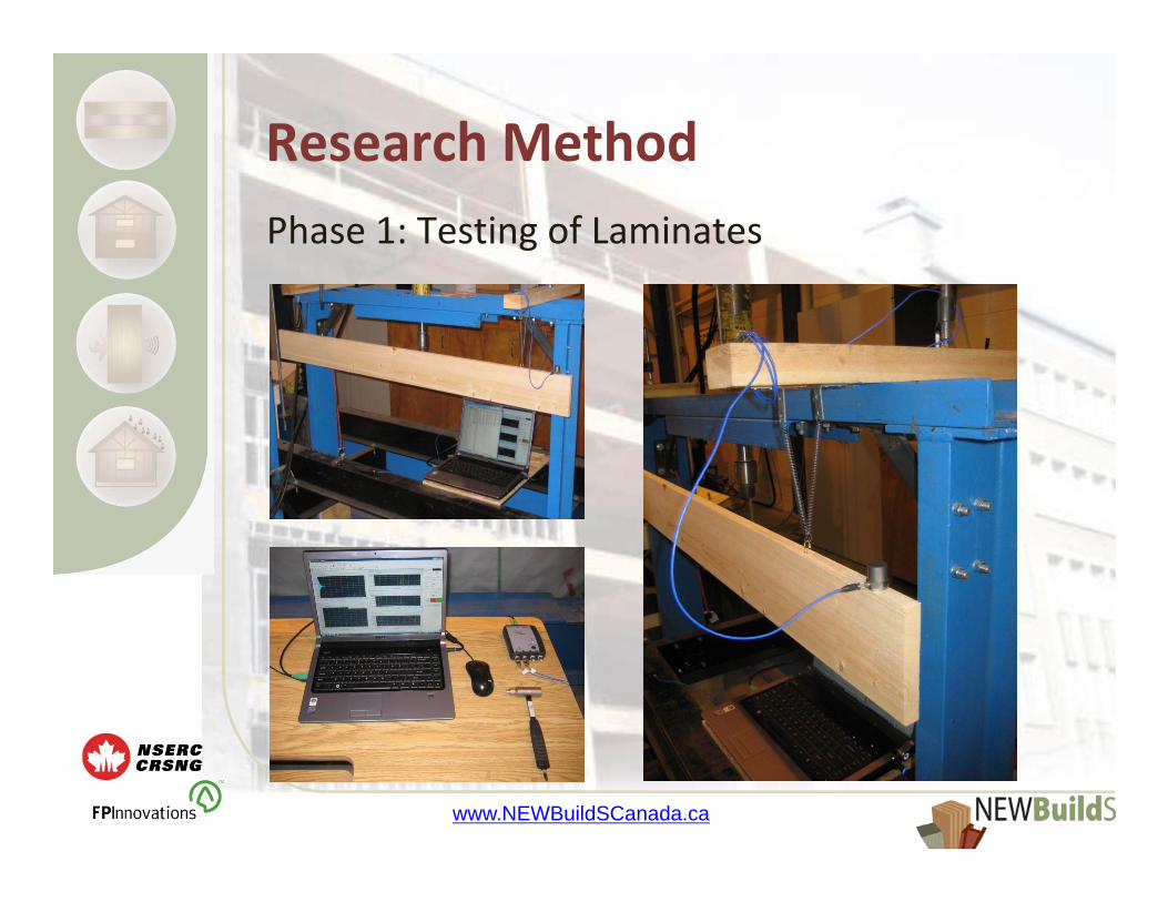
• Modal testing of laminates beam in free‐free vibration conditions in order to determine elastic properties
www.NEWBuildSCanada.ca
Research MethodPhase 1: Testing of Laminates

www.NEWBuildSCanada.ca
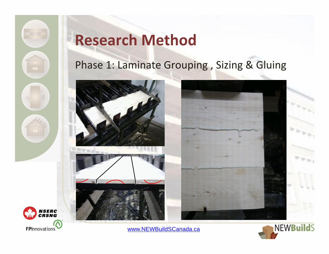
Research MethodPhase 1: Laminate Grouping , Sizing & Gluing
• Grouping of laminates by characteristics (growth ring orientation, stiffness properties)
• Sizing grouped laminates to final width (120mm, 76mm & 32mm) with consideration of defects (avoiding major laminate defects)
• Glue layers from grouped laminates in order to gain ‘homogeneous’ layers (1 component PUR glue)
www.NEWBuildSCanada.ca
Research MethodPhase 1: Laminate Grouping , Sizing & Gluing
www.NEWBuildSCanada.ca
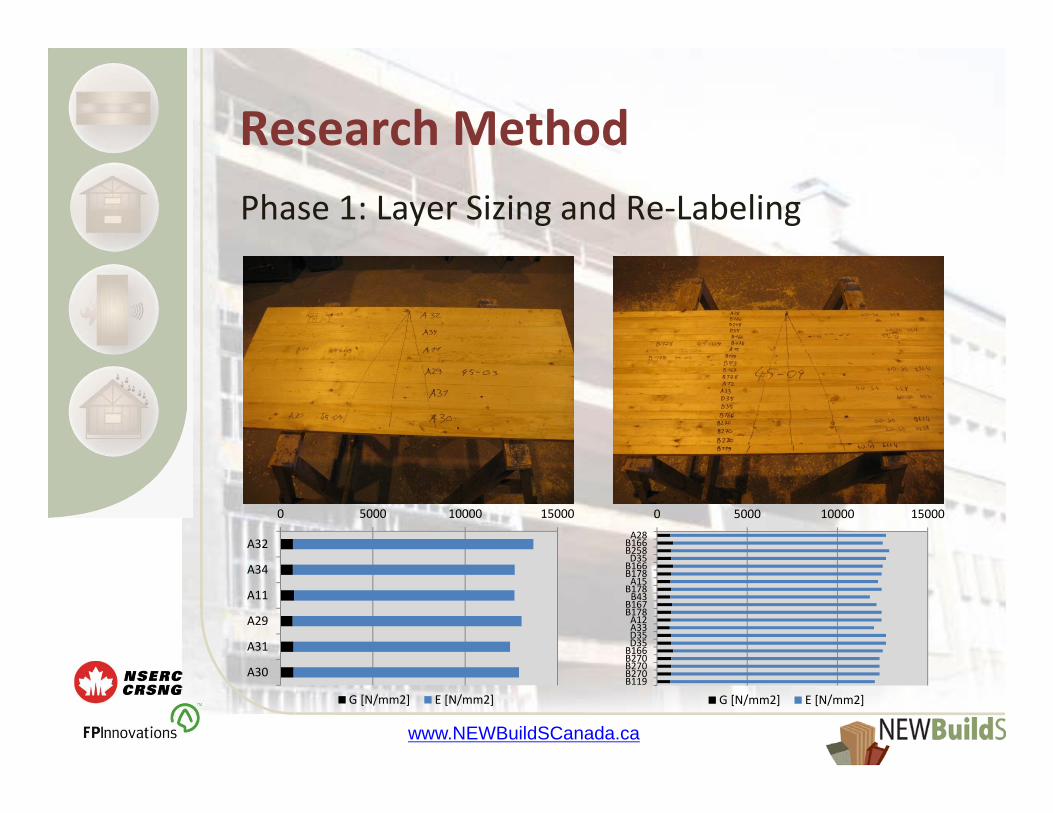
Research MethodPhase 1: Layer Sizing and Re‐Labeling
0 5000 10000 15000
A32
A34
A11
A29
A31
A30
G [N/mm2] E [N/mm2]
0 5000 10000 15000A28B166B258D35B166B178A15B178B43
B167B178A12A33D35D35B166B270B270B270B119
G [N/mm2] E [N/mm2]

www.NEWBuildSCanada.ca
Research MethodPhase 1: Testing of Layer Plates
• Modal testing of layers by methods by Sobue& Katoh and Guelzow et. al.
• Determination of modulus of elasticity & shear modulus
• Static bending tests to verify results of modal testing
www.NEWBuildSCanada.ca
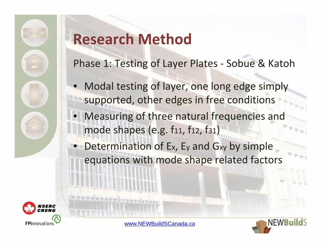
Research MethodPhase 1: Testing of Layer Plates ‐ Sobue & Katoh
• Modal testing of layer, one long edge simply supported, other edges in free conditions
• Measuring of three natural frequencies and mode shapes (e.g. f11, f12, f31)
• Determination of Ex, Ey and Gxy by simple equations with mode shape related factors

www.NEWBuildSCanada.ca
Research MethodPhase 1: Testing of Layer Plates ‐ Sobue & Katoh
www.NEWBuildSCanada.ca
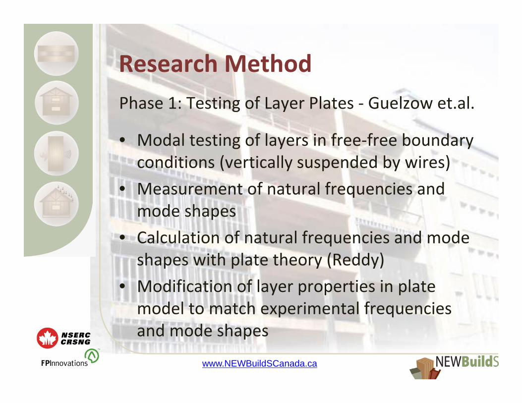
Research MethodPhase 1: Testing of Layer Plates ‐ Guelzow et.al.
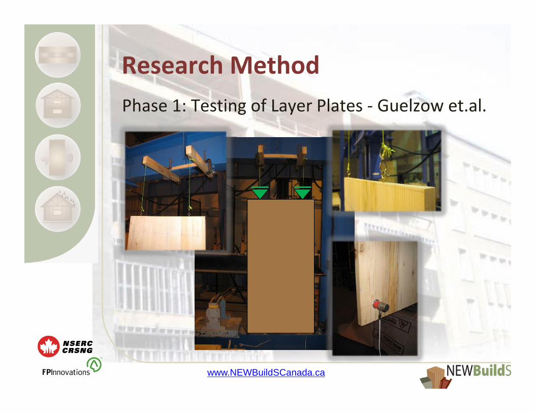
• Modal testing of layers in free‐free boundary conditions (vertically suspended by wires)
• Measurement of natural frequencies and mode shapes
• Calculation of natural frequencies and mode shapes with plate theory (Reddy)
• Modification of layer properties in plate model to match experimental frequencies and mode shapes
www.NEWBuildSCanada.ca
Research MethodPhase 1: Testing of Layer Plates ‐ Guelzow et.al.

www.NEWBuildSCanada.ca
Research MethodPhase 1: Testing of Layer Plates
www.NEWBuildSCanada.ca
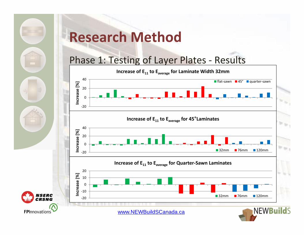
Research MethodPhase 1: Testing of Layer Plates ‐ Results
• No problems to determine natural frequencies and mode shapes
• Comparison between determined natural frequencies and natural frequencies from FEM, based on evaluated stiffness properties (Sobue & Katoh) shows promising results
www.NEWBuildSCanada.ca
Research MethodPhase 1: Testing of Layer Plates ‐ Results
‐20
0
20
40
Increase [%
]
Increase of E11 to Eaverage for 45°Laminates
32mm 76mm 120mm
‐20
‐10
0
10
20
Increase [%
]
Increase of E11 to Eaverage for Quarter‐Sawn Laminates
32mm 76mm 120mm
‐20
0
20
40Increase [%
]Increase of E11 to Eaverage for Laminate Width 32mm
flat‐sawn 45° quarter‐sawn
www.NEWBuildSCanada.ca
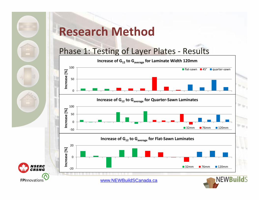
Research MethodPhase 1: Testing of Layer Plates ‐ Results
‐20
0
20
Increase [%
]
Increase of G12 to Gaverage for Flat‐Sawn Laminates
32mm 76mm 120mm
‐50
0
50
100
Increase [%
]
Increase of G12 to Gaverage for Quarter‐Sawn Laminates
32mm 76mm 120mm
0
50
100Increase [%
]Increase of G12 to Gaverage for Laminate Width 120mm
flat‐sawn 45° quarter‐sawn

www.NEWBuildSCanada.ca
Phase 1: CLT Production and Testing
Research Method
www.NEWBuildSCanada.ca
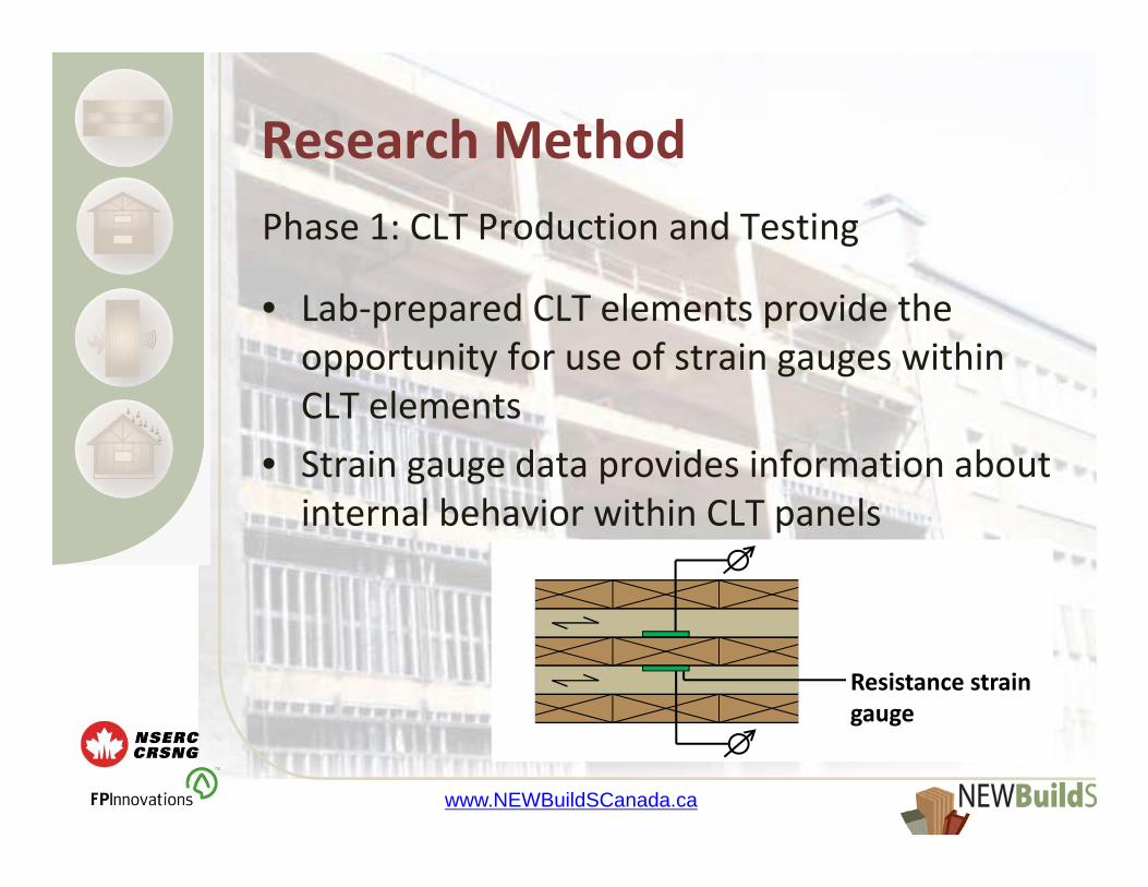
Research MethodPhase 1: CLT Production and Testing
• Lab‐prepared CLT elements provide the opportunity for use of strain gauges within CLT elements
• Strain gauge data provides information about internal behavior within CLT panels
Resistance strain gauge

www.NEWBuildSCanada.ca
Research MethodPhase 1: Analysis of Test Data
• Compare results of modal and static tests • Analyze and evaluate influence of laminate material and manufacturing characteristics on layer and CLT overall characteristics
• Analyze data from strain gauges to assess advanced plate model predictions
www.NEWBuildSCanada.ca
Research MethodPhase 1: Analysis of Test Data
• Analysis of FEM and plate theory models with layer characteristics from laboratory tests
• Comparison between laboratory test results and results from model analysis
• Modify layer characteristics in models to match laboratory test results
• Evaluate relationship between real characteristics and input values

www.NEWBuildSCanada.ca
Research MethodPhase 2: Full‐scale Tests
• Full‐scale tests to evaluate applicability of results of Phase 1 for full‐scale CLT
• Modal tests of full‐scale single‐layer panels for comparison of results from scaled and full‐scale tests
• Estimation of laminate properties (based on modal spot tests) within CLT production
• Evaluation of properties of full‐scale CLT panels by modal test methods

www.NEWBuildSCanada.ca
Research MethodPhase 2: Analysis of Test Data
• Compare scaled and full‐scale results of modal test methods
• Analyze influence of size on evaluated relationships
• Evaluate influence of laminate material and manufacturing characteristics on full‐scale layer and CLT overall characteristics

www.NEWBuildSCanada.ca
Conclusion & Expected OutcomesConducted Work
• Method by Sobue & Katoh appears suitable for single‐layer stiffness evaluation
• Laminate width of 32mm and a growth ring orientation of 45°lead to an increase of E11, quarter‐sawn laminates lead to a reduction of E11
• Laminate width of 120mm, quarter‐sawn and flat‐sawn patterns lead to an increase of G12

www.NEWBuildSCanada.ca
Conclusion & Expected OutcomesUpcoming Research ‐ Expected Outcomes
• Establish relationships between manufacturing characteristics and layer characteristics
• Evaluation of modal testing application• Evaluation of advanced plate model applicability for design use

www.NEWBuildSCanada.ca
Thanks you for your attention!
Influence of Manufacturing Parameters on Rolling Shear Behavior of Cross Laminated Timber
Minghao Li, Ph.D.Department of Wood ScienceThe University of British Columbia
NEWBuildS Annual Workshop, Richmond, BC, May 3rd, 2012 Project ID: T1-6-C1
1

1. Introduction
2. Experimental studies
• Short-term bending tests
• Fatigue bending tests
3. Continuing studies
4. Conclusions
Outlines
2
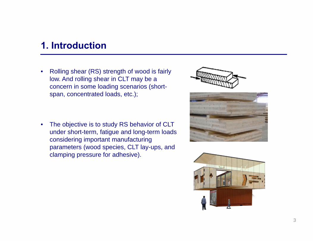
• Rolling shear (RS) strength of wood is fairly low. And rolling shear in CLT may be a concern in some loading scenarios (short-span, concentrated loads, etc.);
• The objective is to study RS behavior of CLT under short-term, fatigue and long-term loads considering important manufacturing parameters (wood species, CLT lay-ups, and clamping pressure for adhesive).
1. Introduction
3

Manufacturing parameters
• 2 Wood species (Hem-fir & S.P.F)
• 3 CLT layups
• 2 Clamping pressure levels for polyurethane adhesive (0.1 MPa & 0.4 MPa)
Species No. of layers
Clamping pressure
(MPa)Laminate Grade
Layer thickness
(mm)
Panel dimension L×W×H (mm)
Hem-fir 50.1
L1/L2/L2/L2/L1 27.5 4000×1219×137.50.4
S.P.F.
50.1
No.2/Stud/No.2/Stud/No.234/19/
34/19/343658×1219×140
0.4
30.1
No.2/Stud/No.2 34 3658×1219×1020.4
4
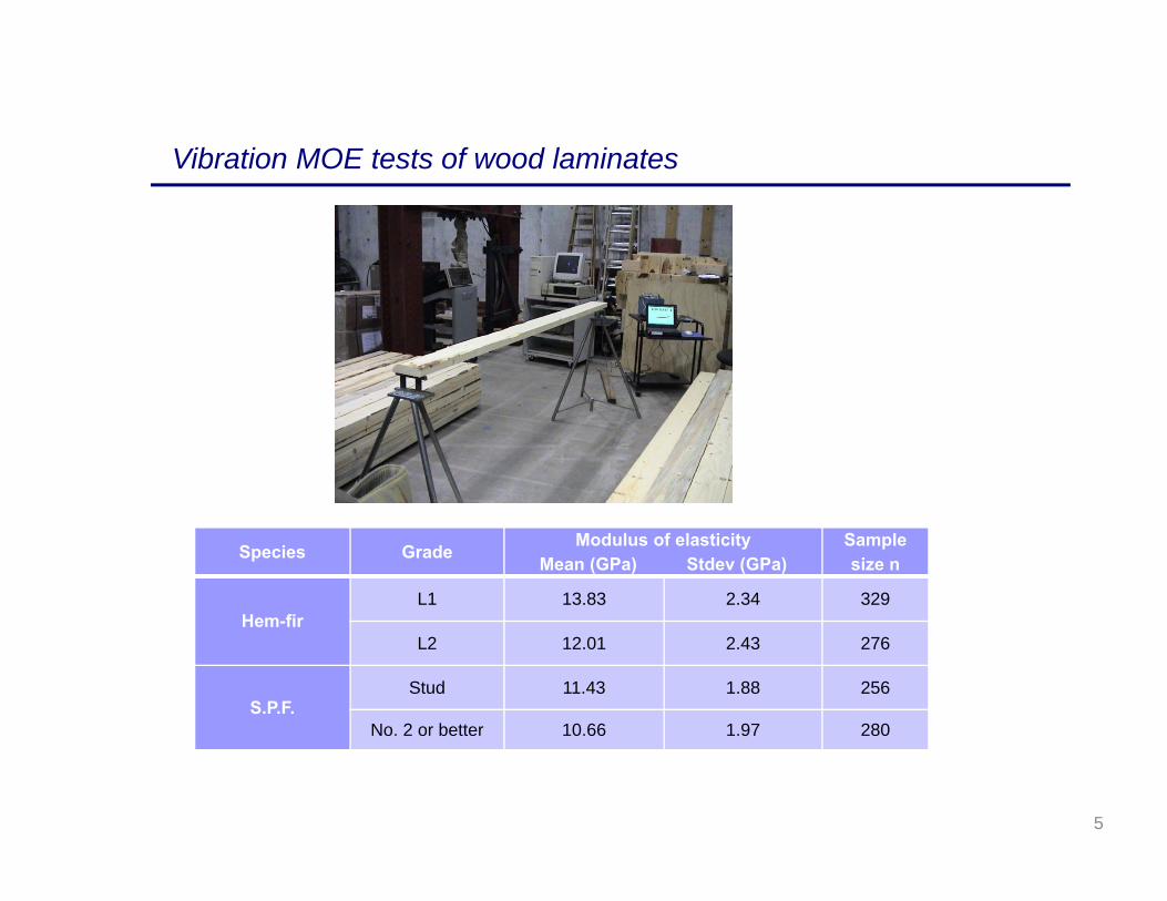
Species Grade Modulus of elasticityMean (GPa) Stdev (GPa)
Sample size n
Hem-firL1 13.83 2.34 329
L2 12.01 2.43 276
S.P.F.Stud 11.43 1.88 256
No. 2 or better 10.66 1.97 280
Vibration MOE tests of wood laminates
5
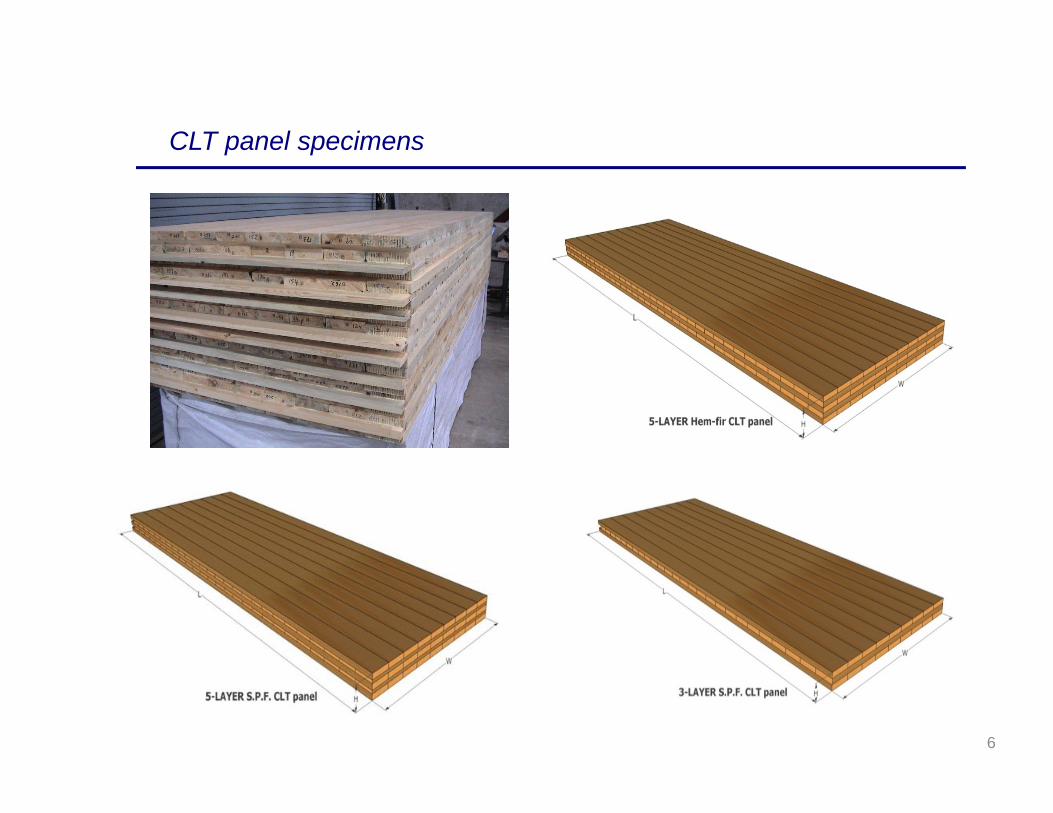
CLT panel specimens
6
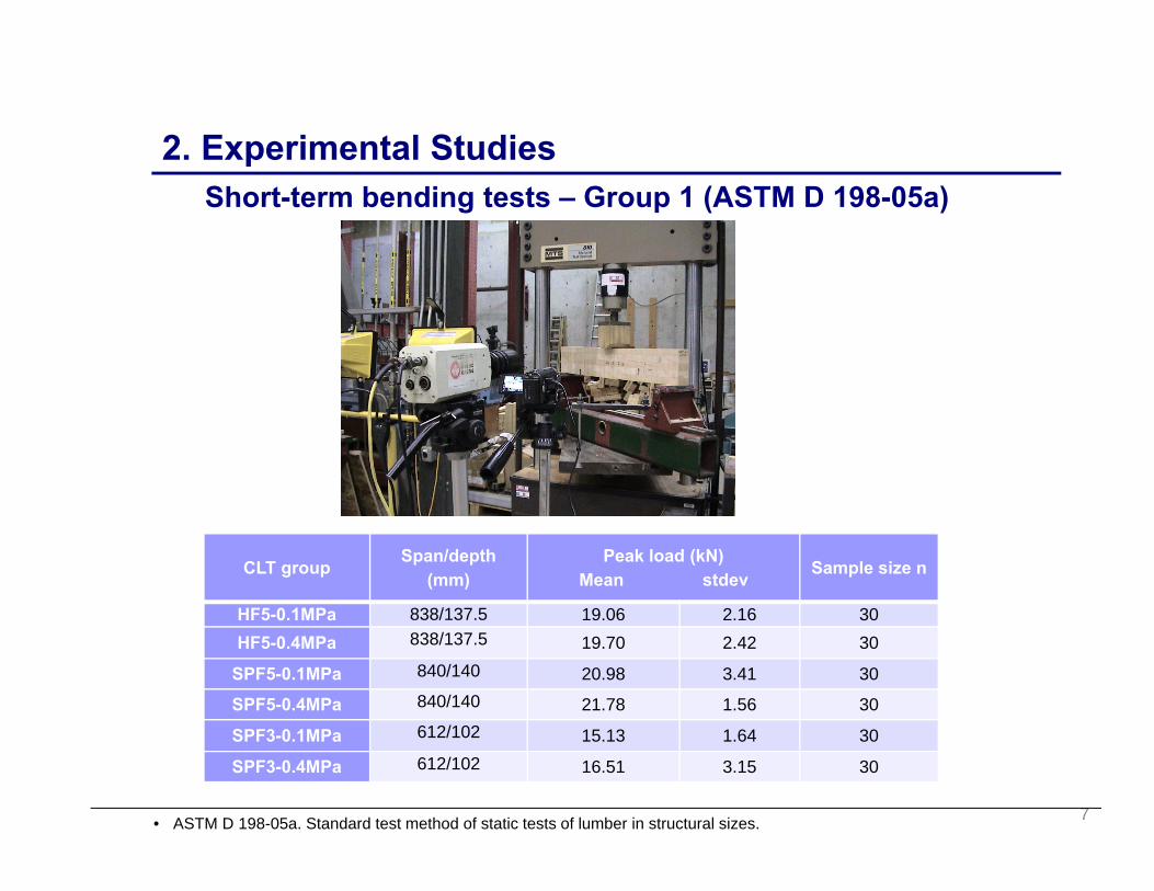
Short-term bending tests – Group 1 (ASTM D 198-05a)
CLT group Span/depth (mm)
Peak load (kN)Mean stdev Sample size n
HF5-0.1MPa 838/137.5 19.06 2.16 30HF5-0.4MPa 838/137.5 19.70 2.42 30
SPF5-0.1MPa 840/140 20.98 3.41 30
SPF5-0.4MPa 840/140 21.78 1.56 30
SPF3-0.1MPa 612/102 15.13 1.64 30
SPF3-0.4MPa 612/102 16.51 3.15 30
2. Experimental Studies
7• ASTM D 198-05a. Standard test method of static tests of lumber in structural sizes.

Cumulative distributions of short-term capacity
0
0.1
0.2
0.3
0.4
0.5
0.6
0.7
0.8
0.9
1
10 15 20 25 30
Cumulative Prob
ability
Peak Load (kN)
HF5‐0.1MPa
HF5‐0.4MPa
0
0.1
0.2
0.3
0.4
0.5
0.6
0.7
0.8
0.9
1
10 15 20 25 30
Cumulative Prob
ability
Peak Load (kN)
SPF5‐0.1MPa
SPF5‐0.4MPa
0
0.1
0.2
0.3
0.4
0.5
0.6
0.7
0.8
0.9
1
10 15 20 25 30
Cumulative Prob
ability
Peak Load (kN)
SPF3‐0.1MPa
SPF3‐0.4MPa
8

Methods to estimate rolling shear strength
• Multi-layer composite beam theory (Bodig & Jayne, 1982)
τVb
• FE Modeling (ANSYS, 2011)
1) Case 1 – no gaps in cross layers and rigid glue line bonding2) Case 2 – no gaps in cross layers and flexible glue line bonding3) Case 3 – with gaps in cross layers and rigid glue line bonding4) Case 4 – with gaps in cross layers and flexible glue line bonding
9• Bodig, J. and Jayne, B. 1982. “Mechanics of wood and wood composites.” Van Nostrand Reinhold Co. Inc. NY, U.S.• ANSYS V11.0. 2011, Swanson Analysis System, Inc. Houston, PA, US
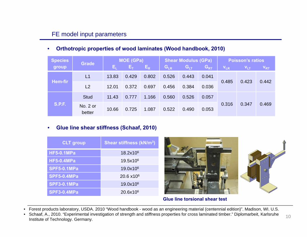
Species group Grade MOE (GPa)
EL ET ER
Shear Modulus (GPa)GLR GLT GRT
Poisson’s ratiosνLR νLT νRT
Hem-firL1 13.83 0.429 0.802 0.526 0.443 0.041
0.485 0.423 0.442L2 12.01 0.372 0.697 0.456 0.384 0.036
S.P.F.Stud 11.43 0.777 1.166 0.560 0.526 0.057
0.316 0.347 0.469No. 2 or better
10.66 0.725 1.087 0.522 0.490 0.053
CLT group Shear stiffness (kN/m3)
HF5-0.1MPa 18.2x10⁶
HF5-0.4MPa 19.5x10⁶
SPF5-0.1MPa 19.0x10⁶
SPF5-0.4MPa 20.6 x10⁶
SPF3-0.1MPa 19.0x10⁶
SPF3-0.4MPa 20.6x10⁶
• Orthotropic properties of wood laminates (Wood handbook, 2010)
FE model input parameters
Glue line torsional shear test
• Glue line shear stiffness (Schaaf, 2010)
10• Forest products laboratory, USDA. 2010 “Wood handbook - wood as an engineering material (centennial edition)”. Madison, WI. U.S.• Schaaf, A., 2010. “Experimental investigation of strength and stiffness properties for cross laminated timber.” Diplomarbeit, Karlsruhe
Institute of Technology. Germany.
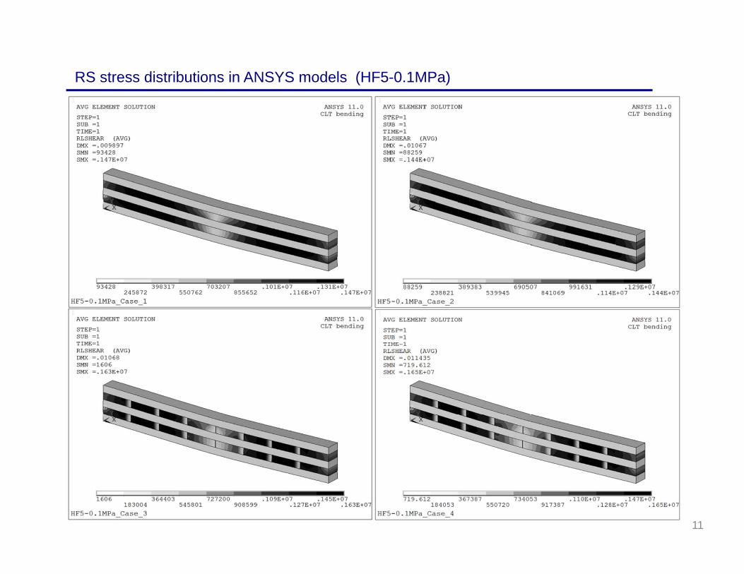
RS stress distributions in ANSYS models (HF5-0.1MPa)
11
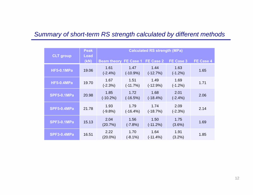
CLT groupPeak Load (kN)
Calculated RS strength (MPa)
Beam theory FE Case 1 FE Case 2 FE Case 3 FE Case 4
HF5-0.1MPa 19.061.61
(-2.4%)1.47
(-10.9%)1.44
(-12.7%)1.63
(-1.2%)1.65
HF5-0.4MPa 19.701.67
(-2.3%)1.51
(-11.7%)1.49
(-12.9%)1.69
(-1.2%)1.71
SPF5-0.1MPa 20.981.85
(-10.2%)1.72
(-16.5%)1.68
(-18.4%)2.01
(-2.4%)2.06
SPF5-0.4MPa 21.781.93
(-9.8%)1.79
(-16.4%)1.74
(-18.7%)2.09
(-2.3%)2.14
SPF3-0.1MPa 15.132.04
(20.7%)1.56
(-7.8%)1.50
(-11.2%)1.75
(3.6%)1.69
SPF3-0.4MPa 16.512.22
(20.0%)1.70
(-8.1%)1.64
(-11.4%)1.91
(3.2%)1.85
Summary of short-term RS strength calculated by different methods
12
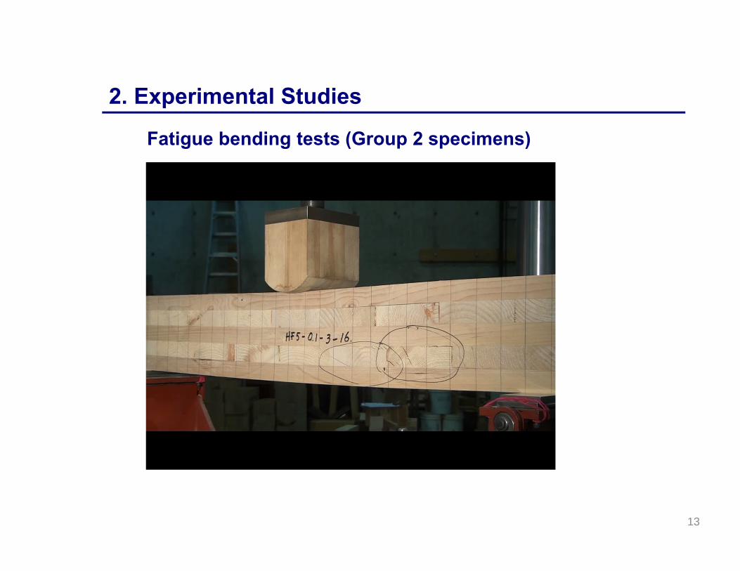
2. Experimental Studies
Fatigue bending tests (Group 2 specimens)
13
14
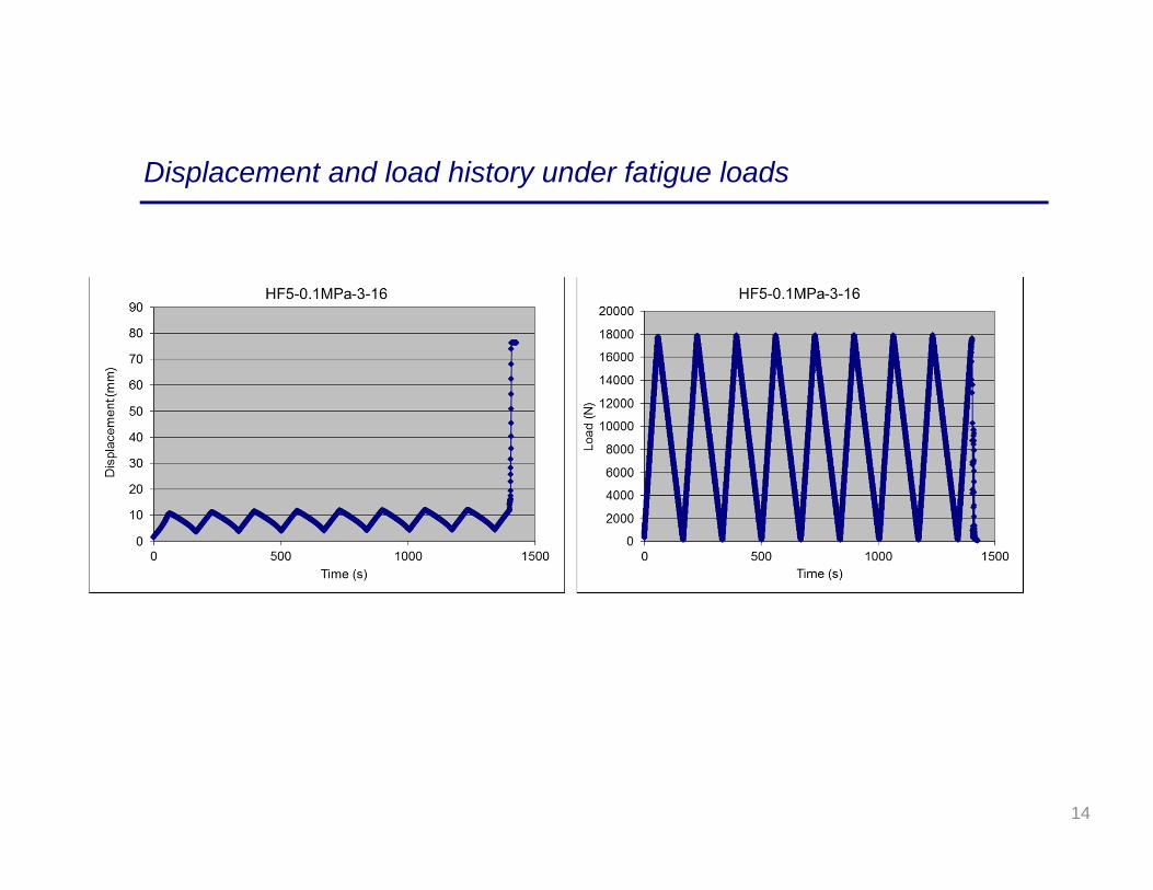
Displacement and load history under fatigue loads
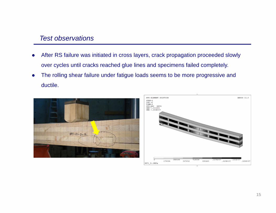
After RS failure was initiated in cross layers, crack propagation proceeded slowly
over cycles until cracks reached glue lines and specimens failed completely.
The rolling shear failure under fatigue loads seems to be more progressive and
ductile.
Test observations
15

Panel No.Average short-term capacity
(N)
25th%-tile Short-term Capacity (N)
Sample size n
No. of Cycles to failureMean Stdev Not fail(>300)
HF5-0.1MPa-1 18337.1 17383.6 10 6 7 0
HF5-0.1MPa-2 21092.0 20353.8 10 74 89 0
HF5-0.1MPa-3 17753.3 15658.4 10 142 128 2
HF5-0.4MPa-1 20256.8 19000.9 10 22 25 0
HF5-0.4MPa-2 19871.6 17407.5 10 36 40 0
HF5-0.4MPa-3 18955.7 17932.1 10 23 35 0
SPF5-0.1MPa-1 23970.0 22843.4 10 25 23 0
SPF5-0.1MPa-2 21917.2 20536.4 10 84 94 1
SPF5-0.4MPa-1 22715.8 21421.0 10 105 89 1
SPF5-0.4MPa-2 20824.7 20116.7 10 101 95 0
SPF5-0.4MPa-3 21785.7 20543.9 10 117 113 1
Fatigue test summary
16

Relationship between stress levels and no. of cycles to failure
17

Complete fatigue bending tests of all Group 2 specimens;
Conduct long-term duration of load tests of Group 3 specimens;
Calibrate and verify damage accumulation models based on the test
database; and
Conduct reliability analysis to quantify long-term behavior using verified
models
3. Continuing Studies
18
4. Conclusions
The beam theory might not be accurate enough to calculate the actual
RS strength for non-edge-glued CLT specimens due to the existing gaps
in cross layers;
The thickness of cross layers in SPF specimens seems to affect short-
term RS strength significantly;
Increasing clamping pressure from 0.1 MPa to 0.4 MPa helps increase
short-term RS strength for HF5 and SPF3 CLT configurations;
Fatigue test results indicated large variability in number of cycles to
failure for the specimens; and
The linear relationship between stress levels and the logarithms of
number of cycles to failure has been observed.
19

• NEWBuildS – NSERC Strategic Research Network for Engineered Wood-based Building Systems;
• Prof. Frank Lam, Mr. George Lee and Mr. Alex Yuan Li from the timber engineering research group at University of British Columbia; and
• CST Innovations
Acknowledgement
20

Thank you for your attention!

www.NEWBuildSCanada.ca
NEWBUILDS WORKSHOPTHEME Ι ‐ T1‐7‐C3
IN‐PLANE STIFFNESS OF CLT DIAPHRAGMS
Sepideh Ashtari (MASc Student, Dept. of Civil Engineering, UBC)
Supervisors:Dr. Terje Haukaas Dr. Frank Lam
May 2012

www.NEWBuildSCanada.ca
Objectives
• In‐plane behaviour of connected CLT panels
• Influential parameters
• Distribution of seismic forces to shear walls
• Recommendations for design
www.NEWBuildSCanada.ca
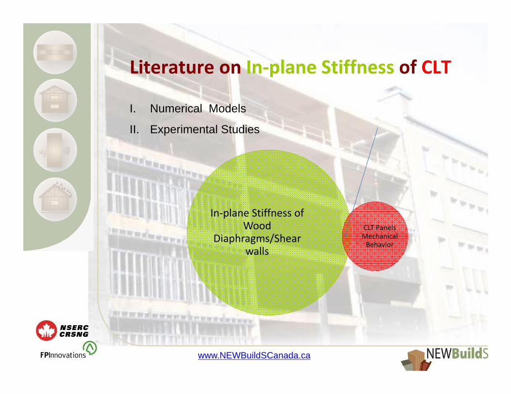
In‐plane Stiffness of Wood
Diaphragms/Shearwalls
CLT Panels Mechanical Behavior
Literature on In‐plane Stiffness of CLT
I. Numerical Models
II. Experimental Studies
www.NEWBuildSCanada.ca
Numerical Models– In‐plane shear stiffness by FEM– Simplified equivalent shear modulus
Experimental Studies– Cyclic and monotonic tests– Force‐Displacement curves

www.NEWBuildSCanada.ca
On‐going Research at UBC
I. Connection Tests at TEAM Laboratory
II. Numerical Modeling in ANSYS

www.NEWBuildSCanada.ca
Connection Tests at UBC
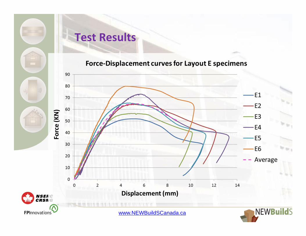
In-plane loading – connection layout E
www.NEWBuildSCanada.ca
Test Results
www.NEWBuildSCanada.ca
Numerical Modeling in ANSYS
• In‐plane stiffness of connected CLT panels
• 2D Local/Globalmodels
• connection test data
• Different Boundary Conditions
• Push‐over curves / Lateral Force Distribution

www.NEWBuildSCanada.ca
Influential Parameters
I. Orthotropic Material Constants
II. Diaphragm Configuration
– Dimensions of Panels
– Number of Connected Panels
III. Nonlinear Curve Parameters of Connections
IV. Boundary Conditions

www.NEWBuildSCanada.ca
Orthotropic Material Constants
Ex 8000 MPa Pxy 0.35Ey 9000 MPa Pyz 0.3Ez 1000 MPa Pxz 0.47Gxy 450 MPaGyz 500 MPaGxz 400 MPa
Selected Material Constants for Numerical Modeling in ANSYS

www.NEWBuildSCanada.ca
Diaphragm Configurations
Configuration 1 Configuration 2
www.NEWBuildSCanada.ca
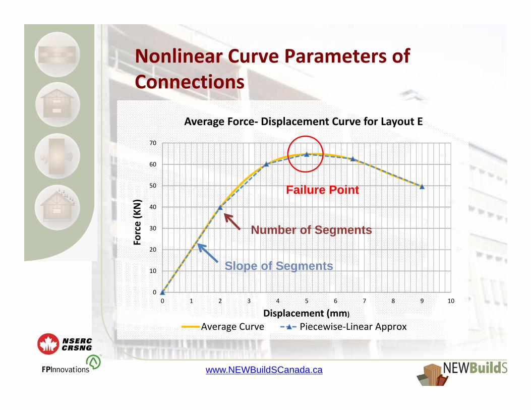
Nonlinear Curve Parameters of Connections
0
10
20
30
40
50
60
70
0 1 2 3 4 5 6 7 8 9 10
Force (KN)
Displacement (mm)
Average Force‐ Displacement Curve for Layout E
Average Curve Piecewise‐Linear Approx
Slope of Segments
Failure Point
Number of Segments
www.NEWBuildSCanada.ca
ANSYS Models
1. Local connection model (validation model)
2. Local diaphragm model
3. Global building model

www.NEWBuildSCanada.ca
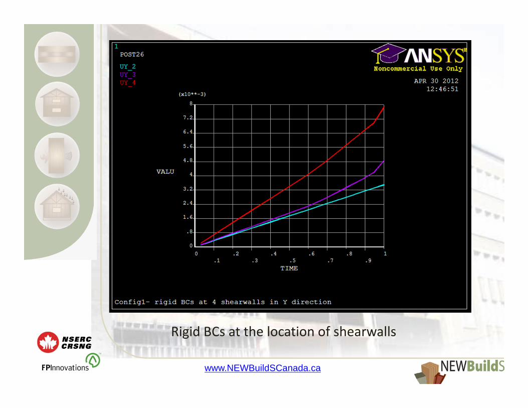
Rigid BCs at the location of shearwalls
www.NEWBuildSCanada.ca
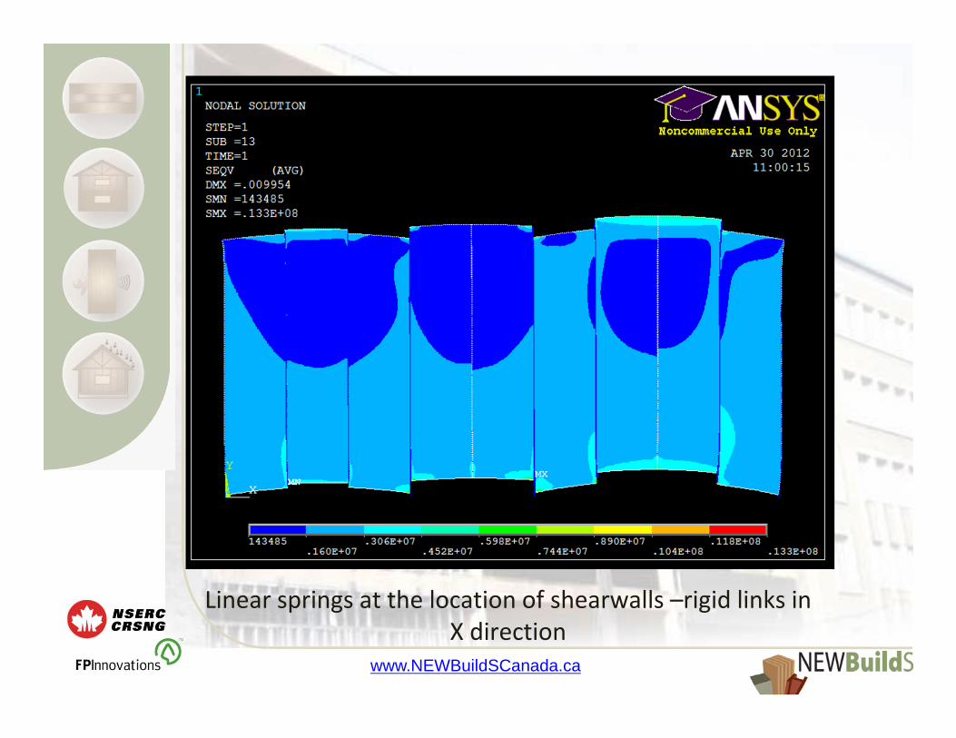
Linear springs at the location of shearwalls –rigid links in X direction

www.NEWBuildSCanada.ca
Linear springs at the location of shearwalls –non‐linear springs in X direction

www.NEWBuildSCanada.ca
Linear springs at the location of shearwalls –non‐linear springs in X direction
www.NEWBuildSCanada.ca
Rigid BCs at the location of shearwalls

www.NEWBuildSCanada.ca
Linear springs at the location of shearwalls –rigid links in X direction

www.NEWBuildSCanada.ca
Linear springs at the location of shearwalls –non‐linear springs in X direction

www.NEWBuildSCanada.ca
Results
• Almost Linear Response
• Non‐linearity source in connections
• Force distribution depending on relative stiffness

www.NEWBuildSCanada.ca
Future Works
• Sensitivity Analysis
• Classifying push‐over curves
• Design recommendations
• Reasonable failure criteria for diaphragms

www.NEWBuildSCanada.ca
Thank You!

T1‐11‐C1Connections in CLT Building Systems
Connections for CLT Diaphragms in Steel‐framed Buildings
Tom Joyce, MScFE CandidateDr. Ian Smith, Supervisor
Faculty of Forestry and Environment ManagementUniversity of New Brunswick
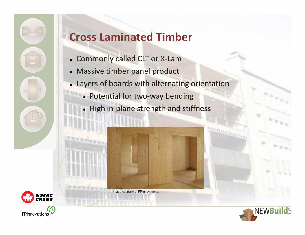
Cross Laminated Timber
Commonly called CLT or X‐Lam Massive timber panel product Layers of boards with alternating orientation
Potential for two‐way bending High in‐plane strength and stiffness
Image courtesy of FPInnovations.
Cross Laminated Timber
Properties influenced by number, arrangement and thickness of layers
Produced and developed originally in Europe Commercially‐available CLT now produced in Canada
Nordic EWP as of June 2011 Structurlam as of September 2011

Cross Laminated Timber
Standard 3‐, 5‐, and 7‐layer options are available with uniform layer thicknesses of 35mm
Can design custom orders 7‐Layer modified to be stiffer in one direction
For this project, considering normal 7‐layer
3-Layer: 105mm 5-Layer: 175mm
7-Layer: 245mm 7-Layer (modified)

CLT Construction in Europe
Massive timber buildings Walls (typically 3‐5 layers)
Large parallel‐to‐grain area Cross layers transfer shear
Floors (typically 7 or more layers) Thicker to reduce vibrations, deflections, carry moments

CLT Construction in Europe
Tall modern timber buildings Stadthaus, London (8+1 storeys) Bridport House, Hackney (8+1 storeys) Plans for timber buildings of 10 – 15 storeys
Stadthaus, Murray Grove, London, UKImage courtesy of Waugh Thistleton Architects
Bridpoirt House, Hackney, UKImage courtesy of Stora Enso.

CLT Construction in N.A.
Typical CLT buildings use large volume of CLT Unlikely to find large market in North America
May find better application in hybrid buildings Building cores – Equilibrium Consulting Diaphragms – Asiz and Smith, 2009, 2010
Image courtesy of Smith and Frangi, 2008

CLT Construction in N.A.
Diaphragm feasibility studied by Asiz and Smith Compared CLT vs. RC (reinforced concrete) floors over steel and RC frames Reduced inter‐storey drift Lower building weight, reduced load on framing and foundation
CLT‐Steel buildings appear to be more efficient than CLT‐RC Higher weight of concrete buildings reduces benefits of light‐weight CLT
Loss of benefits from T‐beam design

Floor Functional Requirements
Ideally, floors and connections should perform well in the following areas... Structurally: acceptable strength and stiffness Fire performance Constructability: ease of assembly, placement, installation
Ability to disperse loads into panels Cost(Adapted roughly from Borg Madsen's Behaviour of Timber Connections)

Project Objectives
Develop a connection capable of meeting requirements needed for the application of CLT as diaphragms in steel‐framed buildings.
Three phase approach: Phase 1 ‐ Investigate existing CLT connections Phase 2 ‐ Design diaphragm and connections Phase 3 ‐ Develop design procedure
Phase 1
Phase 1: Investigation of existing CLT connections: Literature review Design of timber and CLT connections Predicting connection strength Modes of CLT failure, particularly connection failures
Experimental tests Determine benefits of different connection systems, screw diameters, angles
Phase 1 – CLT Connections
Design embedment and withdrawal formulae proposed by Uibel and Blass for CLT Two embedment formulae One based on assumption of uniform properties throughout for thin layers
Other for thicker layers Can be used with existing design codes
Strength and stiffness of line of connections between panels varied by adjusting spacing
Cross‐wise layers restrict splitting Likely can reduce end spacing restrictions

Phase 1 – CLT Connections
Typically connections between CLT wall panels use dowel‐type fasteners
Use splines, laps, or butt joints
For tests, used the two in lower row Double spline and angled (inclined) screws Double spline provides out‐of‐plane moment resistance
Angled screws act more as a hinge
Phase 1 – Method
Testing of CLT connections Loads: Shear and tension loads Stiffness in elastic compression characterized
Fasteners: 8 and 10mm Ecofast ASSY for double spline Partially (Ecofast ASSY) and fully (ASSY VG) threaded screws for angled screws
Load Types: Monotonic – 5 repetitions Cyclic – 2 repetitions
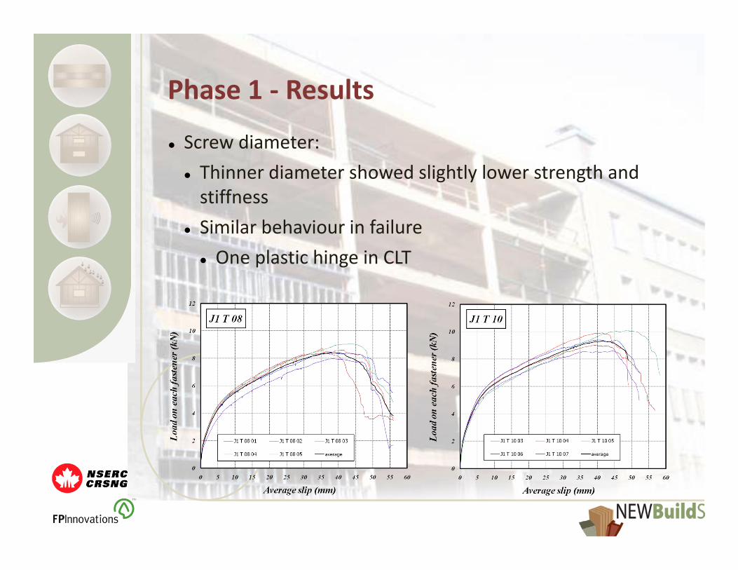
Phase 1 ‐ Results
Screw diameter: Thinner diameter showed slightly lower strength and stiffness
Similar behaviour in failure One plastic hinge in CLT

Phase 1 ‐ Results
Screw angle: Axially loaded screws showed higher stiffness than laterally loaded
Potential for brittle splitting failure of outer laminates with angled screws

Phase 1 ‐ Results
Threaded length: Threading on both sides of angled connections reduces risk of splitting failure
Failure in withdrawal shows highest strength and stiffness of tested connections
Phase 1 ‐ Lessons
Observed failures in CLT were likely result of close proximity of connection to edge of panel Delamination and splitting of outer lamellas Splitting did not extend further into panels
Large diameter screws caused splitting of outer lamellas during assembly
Double spline typically failed in plywood splines Withdrawal gives stronger and stiffer connection Longer threaded length can change failure mode, but can also hinder ease of assembly

Phase 2 ‐ Objectives
Goal is to select a connection for further testing and development
Select steel member for beams Design floors and compared based on set of criteria (allowable spans, deflections...)
Design set of connections for given member Perform tests to determine properties of connections
Compare options and select best, to be tested further in Phase 3
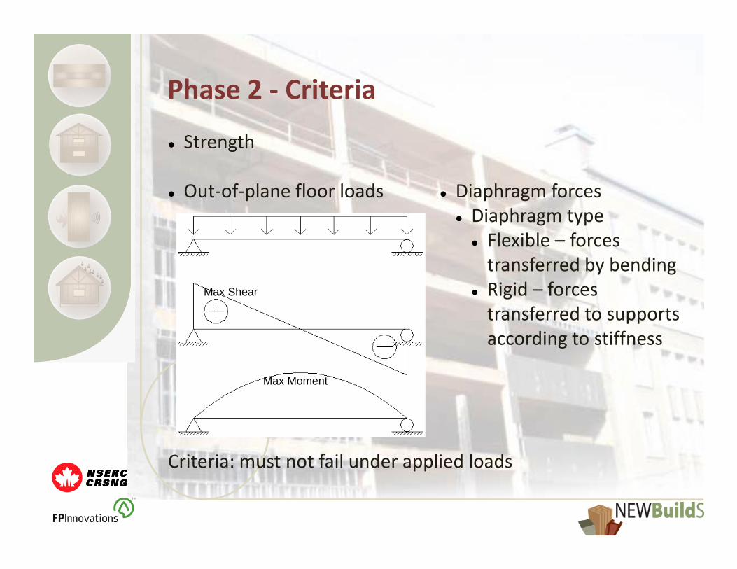
Phase 2 ‐ Criteria
Strength
Out‐of‐plane floor loads
Criteria: must not fail under applied loads
Diaphragm forces Diaphragm type Flexible – forces transferred by bending
Rigid – forces transferred to supports according to stiffness
Max Shear
Max Moment
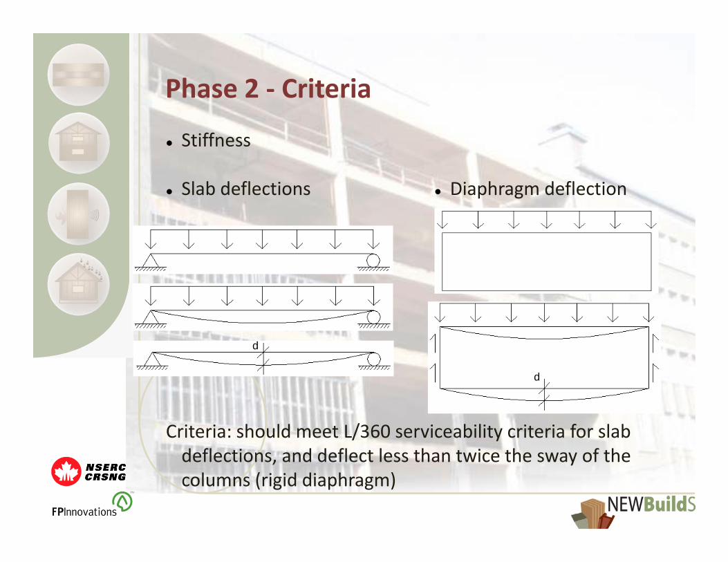
Phase 2 ‐ Criteria
Stiffness
Slab deflections
Criteria: should meet L/360 serviceability criteria for slab deflections, and deflect less than twice the sway of the columns (rigid diaphragm)
Diaphragm deflection
d
d

Phase 2 ‐ Criteria
Deflections and vibrations
Limit spans and allowable loads Influence occupant comfort Potentially damaging to partition walls, windows, and operation of doors
Beam Deflection: Can modify moment of inertia, I, and length
Moment of Inertia: Increases most withincreased depth
Phase 2 ‐ Criteria
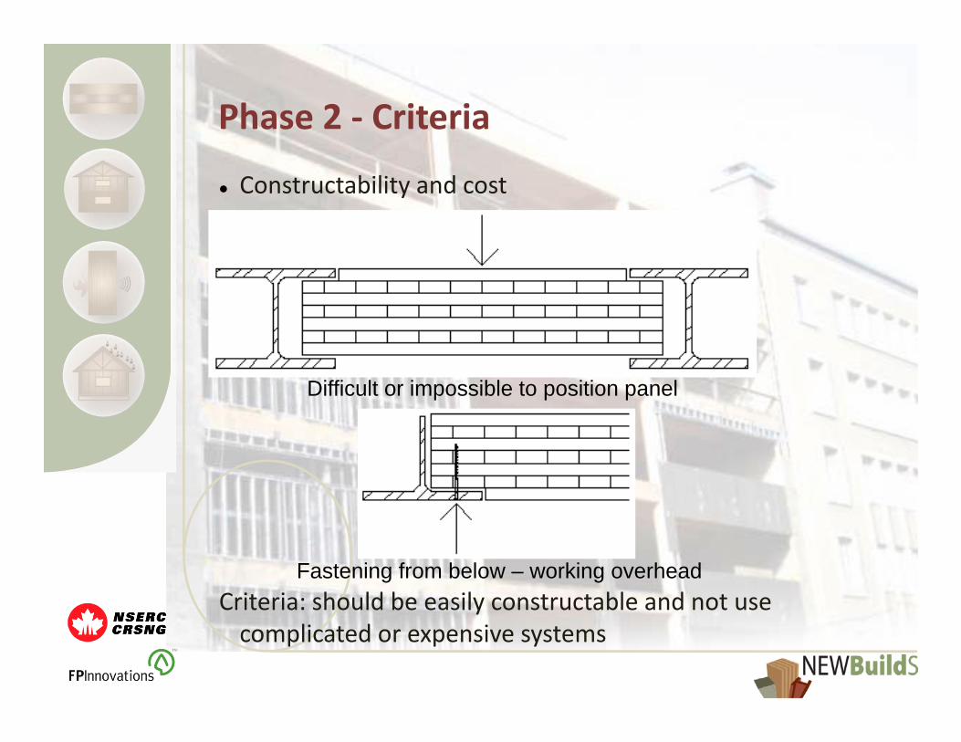
Constructability and cost
Criteria: should be easily constructable and not use complicated or expensive systems
Difficult or impossible to position panel
Fastening from below – working overhead

Phase 2 ‐ Criteria
Eccentric loading of beams and instabilities
Criteria: forces and load cases that may induce buckling of beam or diaphragm should be avoided

Phase 2A ‐Method
Design diaphragm and connections Two general design directions: Slab and Beam Connect CLT simply to steel beam
Plate System Create plate system, possibly with new steel section
Top image courtesy of Kuhlmann et al., 2008Image courtesy of Aziz and Smith, 2009.

Phase 2A ‐Method
Use NBCC 2005 Non‐ground floors of office building: DL: 1.2kPa (concrete) + 1.3kPa (CLT) LL: 2.4kPa (occupancy) + 1.0kPa (partitions)
Select or design beams and determine properties What are the limiting properties? How is the CLT diaphragm influenced by different choices for steel members?
What is the maximum allowable span? Goal is for bays to be larger than 6m Have fewer columns and more open space
Phase 2A ‐ Results
For plates, with depth limited to roughly 245mm, spans were limited by deflection Angles and T‐beams have little steel in compression, which lead to low neutral axes and greater deflection
Moment of inertia of shallow beams was low Overdesigned for shear and bending Two‐way action of panels limited by difference in bending stiffness in both directions EIlongitudinal ~ 10 x EIperpendicular
Phase 2A ‐ Results
For beams and slabs, floor thickness was large Panels over beams created large floor thicknesses Less occupiable space for given height
Could use sub‐beams to provide extra support to CLT and create larger spaces
In some cases there is a risk of instability Potential for buckling of diaphragm
Next step is to select best option and develop connection options given type of steel member

Phase 2B ‐Method
Tests of connection options Create three connection options Static tests with loads acting perpendicular in, perpendicular out, and parallel to beam axis 4 repetitions for each option under each load
Estimate properties of each Elastic stiffness Mode of failure Strengths at yielding and failure
Select a final design for development

Phase 3
Development of design and design procedure Perform additional tests required to characterize properties of system
Where applicable, modifications will be made to determine influence of various factors Fastener diameter, angle, type Steel plate or angle thickness or dimensions Panel orientation

Expected Output
Project oriented around design of connection for CLT diaphragms Identify beams / connection combination Develop design procedure based on experimental findings of strength and stiffness
Results will combine with other work done at UNB on the development of CLT diaphragms and the addressing of potential areas of concern

Thank you for your attention!