Embed Size (px)
Citation preview
8/13/2019 06186765 sdf sdf sdfsdf s
http://slidepdf.com/reader/full/06186765-sdf-sdf-sdfsdf-s 1/4
IEEE ANTENNAS AND WIRELESS PROPAGATION LETTERS, VOL. 11, 2012 423
Collocated Electric and Magnetic Dipoles WithExtremely Low Correlation as a Reference Antenna
for Polarization Diversity MIMO ApplicationsJiang Xiong , Member, IEEE , Mingyu Zhao, Hui Li , Student Member, IEEE , Zhinong Ying , Senior Member, IEEE ,
and Bingzhong Wang , Senior Member, IEEE
Abstract— In this letter, a magnetic dipole (M-dipole) and anelectric dipole (E-dipole) are designed to form a collocated polar-ization-diversity-based dual-antenna system. The M-dipole is amodified shielded loop with multiple feed, and the E-dipole is atraditional dipole. Measured results show that both radiatorshave ideal impedance matching and port isolation and identical
omnidirectional pattern with perfect orthogonal polarization at860 MHz. The upper bound of the envelope correlation coef fi-cient , with the measured antenna ef ficiency taken into
account, is only 0.018, and it is the lowest value when compared tosome previous publications. Excellent effective diversity gain and
channel capacity are also achieved at the operating frequency. Theproposed dual-antenna system can mainly be used as a referenceantenna for evaluating the performance of future collocated polar-ization-diversity-based multiple-input–multiple-output (MIMO)antennas.
Index Terms— Collocated antennas, magnetic dipole (M-dipole),multiple-input–multiple-output (MIMO) systems, polarization
diversity antennas.
I. I NTRODUCTION
M ULTIPLE-INPUT–MULTIPLE-OUTPUT (MIMO)technology is a critical component of the wireless com-
munication system of the next generation. It can significantly
improve the channel capacity and overall performance of the
system without additional spectrum and transmitted power [1].
Due to its compactness, collocated multiple antennas with
polarization diversity have attracted considerable attention for
terminal implementation. In recent years, a bunch of collo-
cated radiating structures for MIMO applications have been
Manuscript received March 06, 2012; revised April 03, 2012; accepted April10, 2012. Date of publication April 18, 2012; date of current version April 26,2012. This work was supported in part by the Fundamental Research Funds for the Central Universities under Grant ZYGX2010J044 and the National ScienceFoundation of China under Grants 61101039 and 61107018.
J. Xiong and B. Wang are with the Computational Electromagnetics Labora-tory, Institute of Applied Physics, University of Electronic Science and Tech-nology of China (UESTC), Chengdu 610054, China (e-mail: [email protected]).
M. Zhao is with State Key Laboratory of Millimeter Waves, School of Infor-mation Science and Engineering, Southeast University, Nanjing 210096, China(e-mail: [email protected]).
H. Li is with the Division of Electromagnetic Engineering, School of Elec-trical Engineering, Royal Institute of Technology, 100 44 Stockholm, Sweden(e-mail: [email protected]).
Z. Ying is with Sony-Ericsson Mobile Communications AB, 221 83 Lund,Sweden (e-mail: [email protected]).
Color versions of one or more of the figures in this letter are available onlineat http://ieeexplore.ieee.org.
Digital Object Identifier 10.1109/LAWP.2012.2195150
Fig. 1. Schematic view of the proposed reference antenna.
proposed [2]–[4]. However, in most practical applications,
polarization diversity and angle diversity always coexist, and
there is a lack of a universal standard for evaluating MIMO
performance improvement such as element correlation and
channel capacity brought by the polarization diversity alone.
The motivation of this work is to design two simple collo-
cated radiating elements [e.g., a pair of collocated electric dipole
(E-dipole) and magnetic dipole (M-dipole)] with identical radi-ation pattern but completely orthogonal polarization, as a “refer-
ence antenna,” and thus its correlation and MIMO performance
can then be taken as a fundamental limit that future practical
collocated polarization diversity antennas (probably of various
antenna types) can approach. The value of building such col-
located dipoles for measuring polarization characteristics of a
polarization diversity system has also been discussed in [5].
In principle, as shown in Fig. 1, a pair of an omnidirectional
E-dipole and loop can form such a reference antenna if the
E-dipole is placed along the central axis of the loop, as an om-
nidirectional loop is equivalent to an M-dipole [6], and the loop
and the E-dipole are highly comparable but with orthogonal po-
larization. However, it is dif ficult to simultaneously achieve an
omnidirectional donut-like radiation pattern, and good radiation
ef ficiency and gain, with either a simple electrically small or
electrically large loop [6]. An ef ficient multiply-fed loop an-
tenna with a moderate electrical size and an omnidirectional pat-
tern has been proposed in [7], yet it utilized a transformer
in the f eeding, which will significantly affect the element isola-
tion if it is collocated with an E-dipole.
In this letter, the loop in [7] is modified so as to be directly
connected with a 50- coaxial line, and it can maintain the typ-
ical omnidirectional radiation pattern of an M-dipole. A conven-
tional E-dipole is then added very close (only ) to the
central axis of such a modified loop. These two radiators form
1536-1225/$31.00 © 2012 IEEE
8/13/2019 06186765 sdf sdf sdfsdf s
http://slidepdf.com/reader/full/06186765-sdf-sdf-sdfsdf-s 2/4
424 IEEE ANTENNAS AND WIRELESS PROPAGATION LETTERS, VOL. 11, 2012
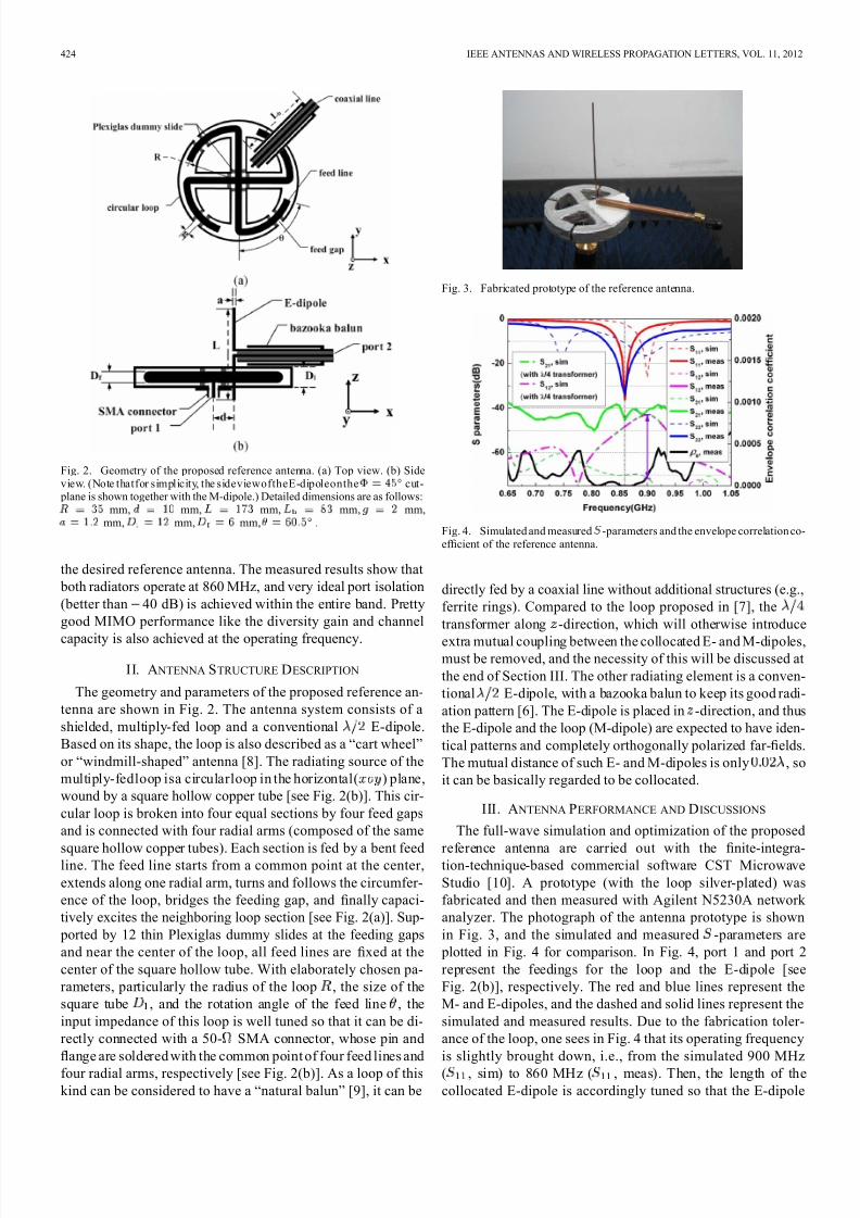
Fig. 2. Geometry of the proposed reference antenna. (a) Top view. (b) Sideview. (Note thatfor simplicity, the sideviewoftheE-dipoleonthe cut- plane is shown together with the M-dipole.) Detailed dimensions are as follows:
mm, mm, mm, mm, mm,mm, mm, mm, .
the desired reference antenna. The measured results show that
both radiators operate at 860 MHz, and very ideal port isolation
(better than 40 dB) is achieved within the entire band. Pretty
good MIMO performance like the diversity gain and channel
capacity is also achieved at the operating frequency.
II. A NTENNA STRUCTURE DESCRIPTION
The geometry and parameters of the proposed reference an-
tenna are shown in Fig. 2. The antenna system consists of a
shielded, multiply-fed loop and a conventional E-dipole.
Based on its shape, the loop is also described as a “cart wheel”
or “windmill-shaped” antenna [8]. The radiating source of the
multiply-fedloop isa circularloop in the horizontal( ) plane,
wound by a square hollow copper tube [see Fig. 2(b)]. This cir-
cular loop is broken into four equal sections by four feed gaps
and is connected with four radial arms (composed of the same
square hollow copper tubes). Each section is fed by a bent feedline. The feed line starts from a common point at the center,
extends along one radial arm, turns and follows the circumfer-
ence of the loop, bridges the feeding gap, and finally capaci-
tively excites the neighboring loop section [see Fig. 2(a)]. Sup-
ported by 12 thin Plexiglas dummy slides at the feeding gaps
and near the center of the loop, all feed lines are fixed at the
center of the square hollow tube. With elaborately chosen pa-
rameters, particularly the radius of the loop , the size of the
square tube , and the rotation angle of the feed line , the
input impedance of this loop is well tuned so that it can be di-
rectly connected with a 50- SMA connector, whose pin and
flange are soldered with the common point of four feed lines and
four radial arms, respectively [see Fig. 2(b)]. As a loop of this
kind can be considered to have a “natural balun” [9], it can be
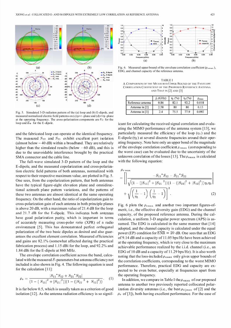
Fig. 3. Fabricated prototype of the reference antenna.
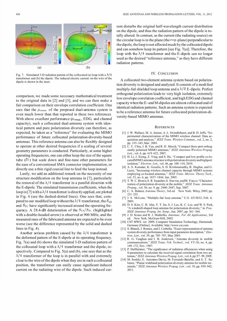
Fig. 4. Simulated and measured -parameters and the envelope correlation co-ef ficient of the reference antenna.
directly fed by a coaxial line without additional structures (e.g.,
ferrite rings). Compared to the loop proposed in [7], the
transformer along -direction, which will otherwise introduce
extra mutual coupling between the collocated E- and M-dipoles,must be removed, and the necessity of this will be discussed at
the end of Section III. The other radiating element is a conven-
tional E-dipole, with a bazooka balun to keep its good radi-
ation pattern [6]. The E-dipole is placed in -direction, and thus
the E-dipole and the loop (M-dipole) are expected to have iden-
tical patterns and completely orthogonally polarized far-fields.
The mutual distance of such E- and M-dipoles is only , so
it can be basically regarded to be collocated.
III. A NTENNA PERFORMANCE AND DISCUSSIONS
The full-wave simulation and optimization of the proposed
reference antenna are carried out with the fi
nite-integra-tion-technique-based commercial software CST Microwave
Studio [10]. A prototype (with the loop silver-plated) was
fabricated and then measured with Agilent N5230A network
analyzer. The photograph of the antenna prototype is shown
in Fig. 3, and the simulated and measured -parameters are
plotted in Fig. 4 for comparison. In Fig. 4, port 1 and port 2
represent the feedings for the loop and the E-dipole [see
Fig. 2(b)], respectively. The red and blue lines represent the
M- and E-dipoles, and the dashed and solid lines represent the
simulated and measured results. Due to the fabrication toler-
ance of the loop, one sees in Fig. 4 that its operating frequency
is slightly brought down, i.e., from the simulated 900 MHz
( , sim) to 860 MHz ( , meas). Then, the length of the
collocated E-dipole is accordingly tuned so that the E-dipole
8/13/2019 06186765 sdf sdf sdfsdf s
http://slidepdf.com/reader/full/06186765-sdf-sdf-sdfsdf-s 3/4
XIONG et al.: COLLOCATED E- AND M-DIPOLES WITH EXTREMELY LOW CORRELATION AS REFERENCE ANTENNA 425
Fig. 5. Simulated 3-D radiation pattern of the (a) loop and (b) E-dipole, and
measured normalized electric field patterns on (c) -plane and (d) -planeat the operating frequency. The cross-polarization components are for theloop and for the E-dipole.
and the fabricated loop can operate at the identical frequency.
The measured and exhibit excellent port isolation
(almost below 40 dB) within a broadband. They are relatively
higher than the simulated results (below 60 dB), and this is
due to the unavoidable interference brought by the practical
SMA connector and the cable line.
The full-wave simulated 3-D pattern of the loop and the
E-dipole, and the measured copolarization and cross-polariza-
tion electric fi
eld patterns of both antennas, normalized withrespect to their respective maximum value, are plotted in Fig. 5.
One sees, from the copolarization pattern, that both antennas
have the typical figure-eight elevation plane and omnidirec-
tional azimuth plane pattern variations, and the patterns of
these two antennas are almost identical at the same operating
frequency. On the other hand, the ratio of copolarization gain to
cross-polarization gain of each antenna in both principle planes
is above 20 dB, with a maximum value of 21.4 dB for the loop
and 21.7 dB for the E-dipole. This indicates both antennas
have good polarization purity, which is important in terms
of accurately measuring cross-polar ratio (XPR) of a radio
environment [5]. This has demonstrated perfect orthogonal
polarization of the two basic dipoles as desired and also guar-
antees the excellent element correlation. Measured ef ficiencies
and gains are 82.1% (somewhat affected during the practical
fabrication process) and 1.15 dBi for the loop, and 92.2% and
1.84 dBi for the E-dipole at 860 MHz.
The envelope correlation coef ficient across the band, calcu-
lated with the measured -parameters but antenna ef ficiency not
included is also shown in Fig. 4. The following equation is used
for the calculation [11]:
(1)
It is far below 0.5, which is usually taken as a criterion of good
isolation [12]. As the antenna radiation ef ficiency is so signif-
Fig. 6. Measured upper bound of the envelope correlation coef ficient ( ),EDG, and channel capacity of the reference antenna.
TABLE IA COMPARISON OF THE MEASURED UPPER BOUND OF THE E NVELOPE
CORRELATION COEFFICIENT OF THE PROPOSED R EFERENCE A NTENNA
AND THAT IN [2] AND [3]
icant for calculating the received signal correlation and evalu-
ating the MIMO performance of the antenna system [13], we
particularly measured the ef ficiency of the loop ( ) and the
E-dipole ( ) at several discrete frequencies around their oper-
ating frequency. Note here only an upper bond of the magnitude
of the envelope correlation coef ficient (corresponding to
the worst case) can be evaluated due to the uncertainty of the
unknown correlation of the losses [13]. The is calculated
with the following equation:
(2)
Fig. 6 plots the and another two important figures-of-
merit, i.e., the effective diversity gain (EDG) and the channel
capacity, of the proposed reference antenna. During the cal-
culation, a uniform 3-D angular power spectrum (APS) is as-
sumed. The EDG is calculated in the same manner that [14]
adopted, and the channel capacity is calculated under the equal power (EP) condition for dB. One sees that an EDG
of 9.14 dB and a capacity of 11.05 bps/Hz have been achieved
at the operating frequency, which is very close to the maximum
achievable performance realized by the i.i.d. channel (i.e., an
EDG of 10 dB and a capacity of 11.29 bps/Hz). It is also worth
noting that the loss-included only gives upper bounds of
the correlation coef ficients, corresponding to the worst MIMO
performance. Therefore, practical EDG and capacity are ex-
pected to be even better, especially at frequencies apart from
the operating frequency.
In addition, we compare in Table I the of our proposed
antenna to another two previously reported collocated polar-
ization diversity antennas (i.e., the best of [2] and the
of [3]), both having excellent performance. For the ease of
8/13/2019 06186765 sdf sdf sdfsdf s
http://slidepdf.com/reader/full/06186765-sdf-sdf-sdfsdf-s 4/4
426 IEEE ANTENNAS AND WIRELESS PROPAGATION LETTERS, VOL. 11, 2012
Fig. 7. Simulated 3-D radiation pattern of the collocated (a) loop with atransformer and (b) the dipole. The induced electric current on the wire of thedipole is shown in the inset.
comparison, we made some necessary mathematical treatment
to the original data in [2] and [3], and we can then make a
fair comparison on their envelope correlation coef ficient. One
sees that the of the proposed dual-antenna system is
even much lower than that reported in these two references.
With above excellent performance ( , EDG, and channel
capacity), such a collocated dual-antenna system with iden-
tical pattern and pure polarization diversity can therefore, as
expected, be taken as a “reference” for evaluating the MIMO
performance of future collocated polarization-diversity-based
antennas. This reference antenna can also be flexibly designed
to operate at other desired frequencies if a scaling of several
geometry parameters is conducted. Particularly, at some higher
operating frequencies, one can either keep the size of the square
tube ( ) but scale down and fine-tune other parameters for
the ease of a conventional SMA connector implementation, or
directly use a thin rigid coaxial line to feed the loop instead.Lastly, we add an additional remark on the necessity of our
structure modification on the loop antenna in [7], particularly
the removal of the transformer in a parallel direction with
the E-dipole. The simulated transmission coef ficients, when the
loop in [7] with a transformer is directly applied, are plotted
in Fig. 4 (see the dashed-dotted lines). One sees that, com-
pared to our modified loop without the transformer, the
and have significantly increased around the operating fre-
quency. A 28.4-dB deterioration of the (highlighted
with a double-headed arrow) is observed at 900 MHz, and the
measured ones of the fabricated antenna are expected to be even
worse (see the difference represented by the solid and dashedlines in Fig. 4).
Another serious problem caused by the transformer is
the deformed pattern of the E-dipole at its operating frequency.
Fig. 7(a) and (b) shows the simulated 3-D radiation pattern of
the collocated loop with a transformer and the dipole, re-
spectively. Compared to Fig. 5(a) and (b), one sees that as the
transformer of the loop is in parallel with and extremely
close to the wire of the dipole when they are in such a collocated
position, the transformer can easily cause significant induced
current on the radiating wire of the dipole. Such induced cur-
rent disturbs the original half-wavelength current distribution
on the dipole, and thus the radiation pattern of the dipole is to-
tally altered. In contrast, as the current (the radiating source) on
the circular loop is in the plane (the -plane) perpendicular to
the dipole, the loop is not affected much by the collocated dipole
and can somehow keep its pattern [see Fig. 7(a)]. Therefore, the
loop with the transformer and the E-dipole can no longer
used as the desired “reference antenna,” as they have different
radiation patterns.
IV. CONCLUSION
A collocated two-element antenna system based on polariza-
tion diversity is designed and analyzed. It consists of a modified
multiply-fed shielded loop antenna and a E-dipole. Perfect
orthogonal polarization leads to very high isolation, extremely
low envelope correlation coef ficient, and high EDG and channel
capacity when the E- and M-dipoles are almost collocated and of
identical radiation patterns. Such an antenna system is expected
to be a reference antenna for future collocated polarization-di-versity-based MIMO antennas.
R EFERENCES
[1] J. W. Wallace, M. A. Jensen, A. L. Swindlehurst, and B. D. Jeffs, “Ex- perimental characterization of the MIMO wireless channel: Data ac-quisition and analysis,” IEEE Trans. Wireless Commun., vol. 2, no. 2, pp. 335–343, Mar. 2003.
[2] C. Y. Chiu, J. B. Yan, and R. D. Murch, “Compact three-port orthog-onally polarised MIMO antennas,” IEEE Antennas Wireless Propag.
Lett., vol. 6, pp. 619–622, 2007.[3] H. Li, J. Xiong, Z. Ying, and S. He, “Compact and low profile co-lo-
catedMIMO antenna structure with polarization diversity and highportisolation,” Electron. Lett., vol. 46, pp. 108–110, 2010.
[4] A. S. Konanur, K. Gosalia, S. H. Krishnamurthy, B. Hughes, and G.Lazzi, “Increasing wireless channel capacity through MIMO systemsemploying co-located antennas,” IEEE Trans. Microw. Theory Tech.,vol. 53, no. 6, pp. 1837–1844, Jun. 2005.
[5] T. W. C. Brown,S. R. Saunders,S. Stavrou, andM. Fiacco, “Character-ization of polarization diversity at the mobile,” IEEE Trans. Antennas
Propag., vol. 56, no. 9, pp. 2440–2447, Sep. 2007.[6] C. A. Balanis , A ntenna Theory, 3rd ed. New York: Wiley, 2005, pp.
231–255.[7] J. S. McLean, “Multiply-fed loop antenna,” U.S. 6515632, Feb. 4,
2003.[8] D. S. Kim, C. H. Ahn, Y. T. Im, S. J. Lee, K. C. Lee, and W. S. Park,
“A windmill-shaped loop antenna for polarization diversity,” in Proc. IEEE Antennas Propag. Int. Symp., Jun. 2007, pp. 361–364.
[9] J. D. Kraus and R. J. Marhefka , Antennas: For All Applications, 3rded. New York: McGraw-Hill, 2002.
[10] CST MWS. ver. 2009, Computer Simulation Technology, Darmstadt,
Germany [Online]. Available: http://www.cst.com[11] S. Blanch, J. Romeu, and I. Corbella, “Exact representation of antenna
system diversity performance from input parameter description,” Elec-tron. Lett., vol. 39, pp. 705–707, May 2003.
[12] R. G. Vaughan and J. B. Andersen, “Antenna diversity in mobilecommunications,” IEEE Trans. Veh. Technol., vol. VT-36, no. 4, pp.149–172, Nov. 1987.
[13] P. Hallbjörner, “The significance of radiation ef ficiencies when usingS-parameters to calculate the received signal correlation from two an-tennas,” IEEE Antennas Wireless Propag. Lett., vol. 4, pp.97–99, 2005.
[14] M. Sonkki, E. Antonino-Daviu, M. Ferrando-Bataller, and E. T. Sa-lonen, “Planar wideband polarization diversity antenna for mobile ter-minals,” IEEE Antennas Wireless Propag. Lett. , vol. 10, pp. 939–942,2011.


![xfyf]{sdf / fli6«o jfl0fHo a} s s f ]!^* cf}+ zfvf :yfkgf · xfyf]{sdf / fli6«o jfl0fHo a} s s f ]!^* cf}+ zfvf :yfkgf a} +s ePsf hgtfnfO] n] { lgw{Ss;+u sf/ f] jf/ u/ L a} lsË](https://img.dokumen.tips/doc/110x75/5e14b6cdae6a754b85680c7c/xfyfsdf-fli6o-jfl0fho-a-s-s-f-cf-zfvf-yfkgf-xfyfsdf-fli6o-jfl0fho.jpg)