Embed Size (px)
Citation preview
WQ XX-XXXX
County of Orange/Santa Ana Region Priority Project
Water Quality Management Plan (WQMP)
Project Name:
ORANGE COUNTY JUVENILE HALL MULTIPURPOSE REHABILITATION CENTER INSERT GRADING PERMIT NO., BUILDING PERMIT NO., OR PLANNING APPLICATION NO.,
PROJECT SITE ADDRESS, TRACT/LOT NUMBER(S), AND APN
Prepared for:
ORANGE COUNTY PUBLIC WORKS 300 N. Flower Street,
Santa Ana, CA 92703
714-667-4926
Prepared by:
KIMLEY-HORN AND ASSOCIATES, INC.
660 S. Figueroa Street, Suite 2050
Los Angeles, CA 90017
213-261-4098
April 2016
Water Quality Management Plan (WQMP)
ORANGE COUNTY JUVENILE HALL MULTIPURPOSE REHABILITATION CENTER
Orange County Public Works Section I
Water Quality.docx Page i
This Water Quality Management Plan (WQMP) has been prepared for the County of Orange
Public Works by Kimley-Horn and Associates, Inc. The WQMP is intended to comply with the
requirements of the County of Orange NPDES Stormwater Program requiring the preparation
of the plan.
The undersigned, while it owns the subject property, is responsible for the implementation of
the provisions of this plan , including the ongoing operation and maintenance of all best
management practices (BMPs), and will ensure that this plan is amended as appropriate to
reflect up-to-date conditions on the site consistent with the current Orange County Drainage
Area Management Plan (DAMP) and the intent of the non-point source NPDES Permit for
Waste Discharge Requirements for the County of Orange, Orange County Flood Control
District and the incorporated Cities of Orange County within the Santa Ana Region. Once the
undersigned transfers its interest in the property, its successors-in-interest shall bear the
aforementioned responsibility to implement and amend the WQMP. An appropriate number of
approved and signed copies of this document shall be available on the subject site in perpetuity.
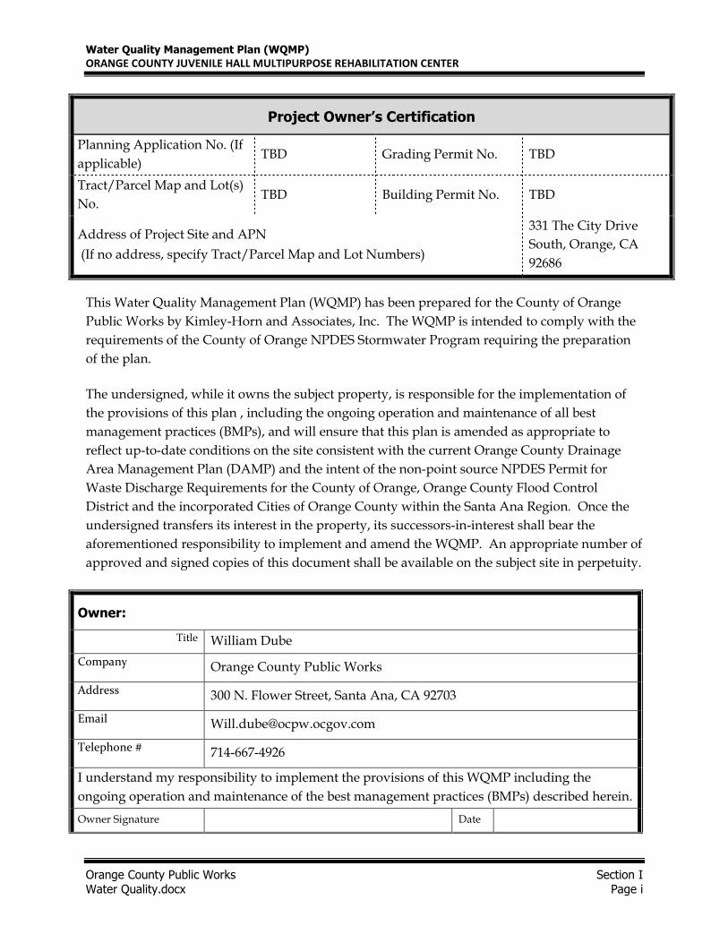
Owner:
Title William Dube
Company Orange County Public Works
Address 300 N. Flower Street, Santa Ana, CA 92703
Email [email protected]
Telephone # 714-667-4926
I understand my responsibility to implement the provisions of this WQMP including the
ongoing operation and maintenance of the best management practices (BMPs) described herein.
Owner Signature Date
Project Owner’s Certification
Planning Application No. (If
applicable) TBD Grading Permit No. TBD
Tract/Parcel Map and Lot(s)
No. TBD Building Permit No. TBD
Address of Project Site and APN
(If no address, specify Tract/Parcel Map and Lot Numbers)
331 The City Drive
South, Orange, CA
92686
Water Quality Management Plan (WQMP)
ORANGE COUNTY JUVENILE HALL MULTIPURPOSE REHABILITATION CENTER
Orange County Public Works Section I
Water Quality.docx Page ii
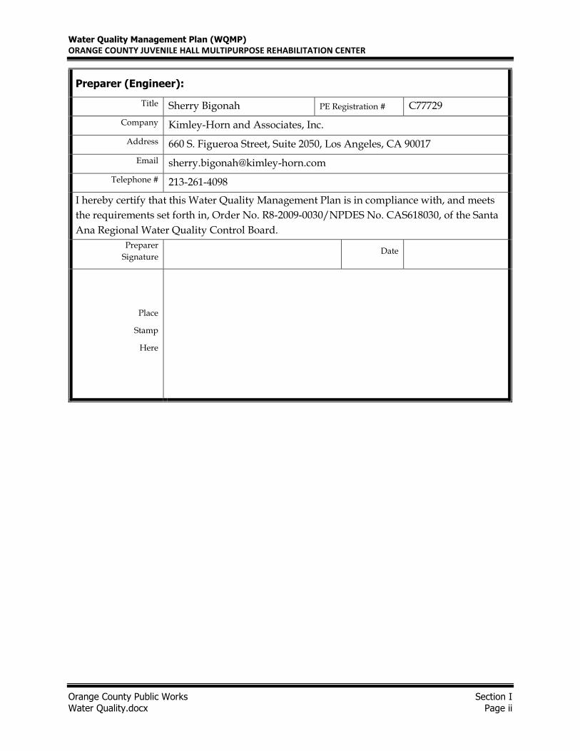
Preparer (Engineer):
Title Sherry Bigonah PE Registration # C77729
Company Kimley-Horn and Associates, Inc.
Address 660 S. Figueroa Street, Suite 2050, Los Angeles, CA 90017
Email [email protected]
Telephone # 213-261-4098
I hereby certify that this Water Quality Management Plan is in compliance with, and meets
the requirements set forth in, Order No. R8-2009-0030/NPDES No. CAS618030, of the Santa
Ana Regional Water Quality Control Board.
Preparer
Signature Date
Place
Stamp
Here
Water Quality Management Plan (WQMP)
ORANGE COUNTY JUVENILE HALL MULTIPURPOSE REHABILITATION CENTER
OC Juvenile Hall MRC Table of Contents Water Quality.docx Page iii
Contents
Section I Permit(s) and Water Quality Conditions of Approval or Issuance ....................... 1
Section II Project Description ........................................................................................... 3
Section III Site Description ................................................................................................ 6
Section IV Best Management Practices (BMPs) ................................................................. 8
Section V Inspection/Maintenance Responsibility for BMPs ........................................... 20
Section VI BMP Exhibit (Site Plan) ................................................................................... 24
Section VII Educational Materials ..................................................................................... 25
Appendices
Attachment A .................................................................... 303d List Of Impaired Water Bodies
Attachment B .......................................................................... County Soils And Rainfall Maps
Attachment C ........................................................................................... Geotechnical Report
Attachment D ........................................................................................................ Calculations
Attachment E ........................................................................................... Education Materials
Attachment F .......................................................................................................... O&M Plan
Attachment G ............................................................................... Conceptual WQMP Site Plan
Attachment H ................................................................................... Transfer of Responsibility
Water Quality Management Plan (WQMP)
ORANGE COUNTY JUVENILE HALL MULTIPURPOSE REHABILITATION CENTER
OC Juvenile Hall MRC Section I Water Quality.docx Page 1
Section I Permit(s) and Water Quality Conditions of Approval or Issuance
Project Infomation
Permit/Application No.
(If applicable) TBD
Grading or Building
Permit No.
(If applicable)
TBD
Address of Project Site
(or Tract Map and Lot
Number if no address)
and APN
331 The City Drive South
Orange, CA 92686
Water Quality Conditions of Approval or Issuance
Water Quality
Conditions of Approval
or Issuance applied to
this project.
(Please list verbatim.)
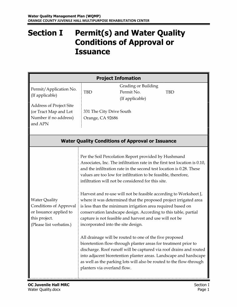
Per the Soil Percolation Report provided by Hushmand
Associates, Inc. The infiltration rate in the first test location is 0.10,
and the infiltration rate in the second test location is 0.28. These
values are too low for infiltration to be feasible, therefore,
infiltration will not be considered for this site.
Harvest and re-use will not be feasible according to Worksheet J,
where it was determined that the proposed project irrigated area
is less than the minimum irrigation area required based on
conservation landscape design. According to this table, partial
capture is not feasible and harvest and use will not be
incorporated into the site design.
All drainage will be routed to one of the five proposed
bioretention flow-through planter areas for treatment prior to
discharge. Roof runoff will be captured via roof drains and routed
into adjacent bioretention planter areas. Landscape and hardscape
as well as the parking lots will also be routed to the flow-through
planters via overland flow.
Water Quality Management Plan (WQMP)
ORANGE COUNTY JUVENILE HALL MULTIPURPOSE REHABILITATION CENTER
OC Juvenile Hall MRC Section I Water Quality.docx Page 2
Conceptual WQMP
Was a Conceptual Water
Quality Management
Plan previously
approved for this
project?
A conceptual WQMP was not already approved for this project.
This is the preliminary conceptual report.
Watershed-Based Plan Conditions
Provide applicable
conditions from watershed
- based plans including
WIHMPs and TMDLS.
TMDLs for the Santa Ana River Reach 2 include Indicator
Bacteria.
Water Quality Management Plan (WQMP)
ORANGE COUNTY JUVENILE HALL MULTIPURPOSE REHABILITATION CENTER
OC JUVENILE HALL MRC Section II Water Quality.docx Page 3
Section II Project Description
II.1 Project Description
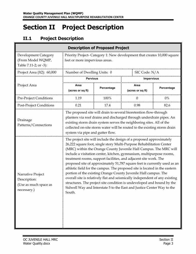
Description of Proposed Project
Development Category
(From Model WQMP,
Table 7.11-2; or -3):
Priority Project- Category 1: New development that creates 10,000 square
feet or more impervious areas.
Project Area (ft2): 60,000 Number of Dwelling Units: 0 SIC Code: N/A
Project Area
Pervious Impervious
Area
(acres or sq ft) Percentage
Area
(acres or sq ft) Percentage
Pre-Project Conditions 1.19 100% 0 0%
Post-Project Conditions 0.21 17.4 0.98 82.6
Drainage
Patterns/Connections
The proposed site will drain to several bioretention flow-through
planters via roof drains and discharged through underdrain pipes. An
existing storm drain system serves the neighboring sites. All of the
collected on-site storm water will be routed to the existing storm drain
system via pipe and gutter flow.
Narrative Project
Description:
(Use as much space as
necessary.)
The project site will include the design of a proposed approximately
26,222 square foot, single story Multi-Purpose Rehabilitation Center
(MRC) within the Orange County Juvenile Hall Campus. The MRC will
include a visitation center, kitchen, gymnasium, multipurpose rooms,
treatment rooms, support facilities, and adjacent site work. The
proposed site of approximately 51,787 square feet is currently used as an
athletic field for the campus. The proposed site is located in the eastern
portion of the existing Orange County Juvenile Hall campus. The
overall site is relatively flat and seismically independent of any existing
structures. The project site condition is undeveloped and bound by the
Sidwell Way and Interstate 5 to the East and Justice Center Way to the
South.
Water Quality Management Plan (WQMP)
ORANGE COUNTY JUVENILE HALL MULTIPURPOSE REHABILITATION CENTER
OC JUVENILE HALL MRC Section II Water Quality.docx Page 4
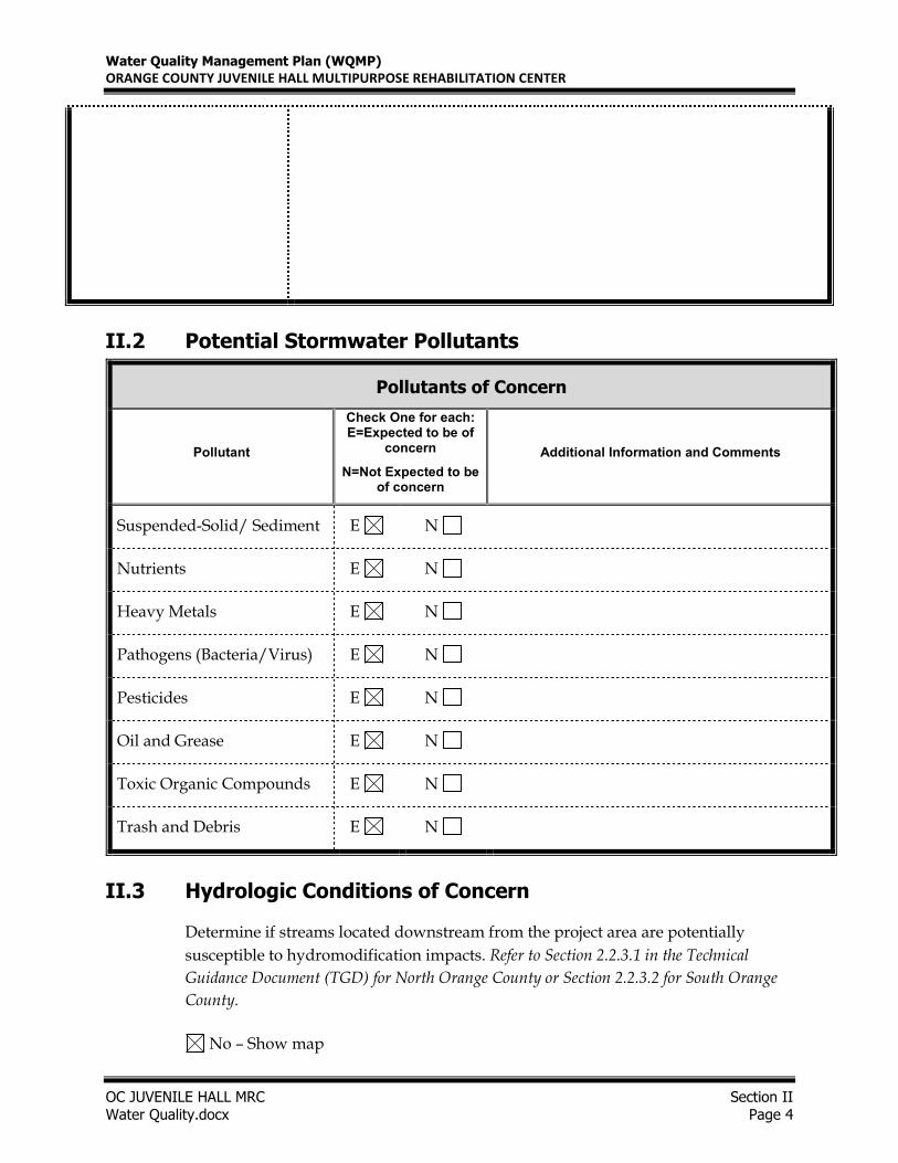
II.2 Potential Stormwater Pollutants
Pollutants of Concern
Pollutant
Check One for each: E=Expected to be of
concern
N=Not Expected to be of concern
Additional Information and Comments
Suspended-Solid/ Sediment E N
Nutrients E N
Heavy Metals E N
Pathogens (Bacteria/Virus) E N
Pesticides E N
Oil and Grease E N
Toxic Organic Compounds E N
Trash and Debris E N
II.3 Hydrologic Conditions of Concern
Determine if streams located downstream from the project area are potentially
susceptible to hydromodification impacts. Refer to Section 2.2.3.1 in the Technical
Guidance Document (TGD) for North Orange County or Section 2.2.3.2 for South Orange
County.
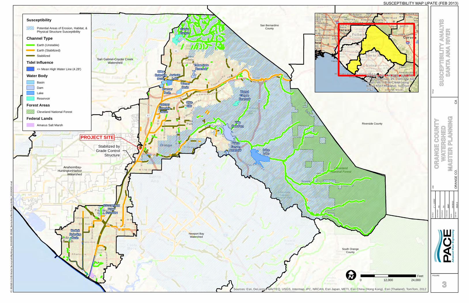
No – Show map
Water Quality Management Plan (WQMP)
ORANGE COUNTY JUVENILE HALL MULTIPURPOSE REHABILITATION CENTER
OC JUVENILE HALL MRC Section II 2016.04.29- Prelim WQMP.docx Page 5
Based on the Orange County Susceptibility Map, the project site is not located in a potential area of
erosion, habitat, and physical structure susceptibility. A portion of the Santa Ana River channel that
is downstream of the project site is classified as a stabilized earth channel. Therefore, the steams
located downstream of the project site are not susceptible to hydromodification impacts.
II.4 Post Development Drainage Characteristics
The proposed site will drain to several bio-retention flow-through planters via roof drains and
discharged via underdrain pipes. An existing storm drain system serves the neighboring sites. All
of the collected on-site storm water will be routed to the existing storm drain system via pipe and
gutter flow.
II.5 Property Ownership/Management
This report is provided for the Orange County Department of Public Works. The property is
owned and will be maintained by the County of Orange. This project is located on the existing
Orange County Juvenile Hall Campus site. See Attachment H for a sample of the Notice of Transfer
required for this project.
Water Quality Management Plan (WQMP)
ORANGE COUNTY JUVENILE HALL MULTIPURPOSE REHABILITATION CENTER
Error! Reference source not found. Section III Water Quality.docx Page 6
Section III Site Description
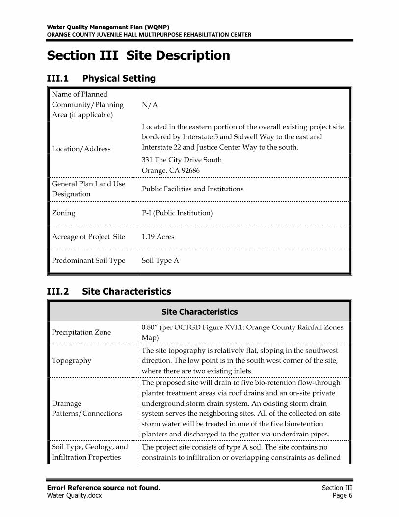
III.1 Physical Setting
Name of Planned
Community/Planning
Area (if applicable)
N/A
Location/Address
Located in the eastern portion of the overall existing project site
bordered by Interstate 5 and Sidwell Way to the east and
Interstate 22 and Justice Center Way to the south.
331 The City Drive South
Orange, CA 92686
General Plan Land Use
Designation Public Facilities and Institutions
Zoning P-I (Public Institution)
Acreage of Project Site 1.19 Acres
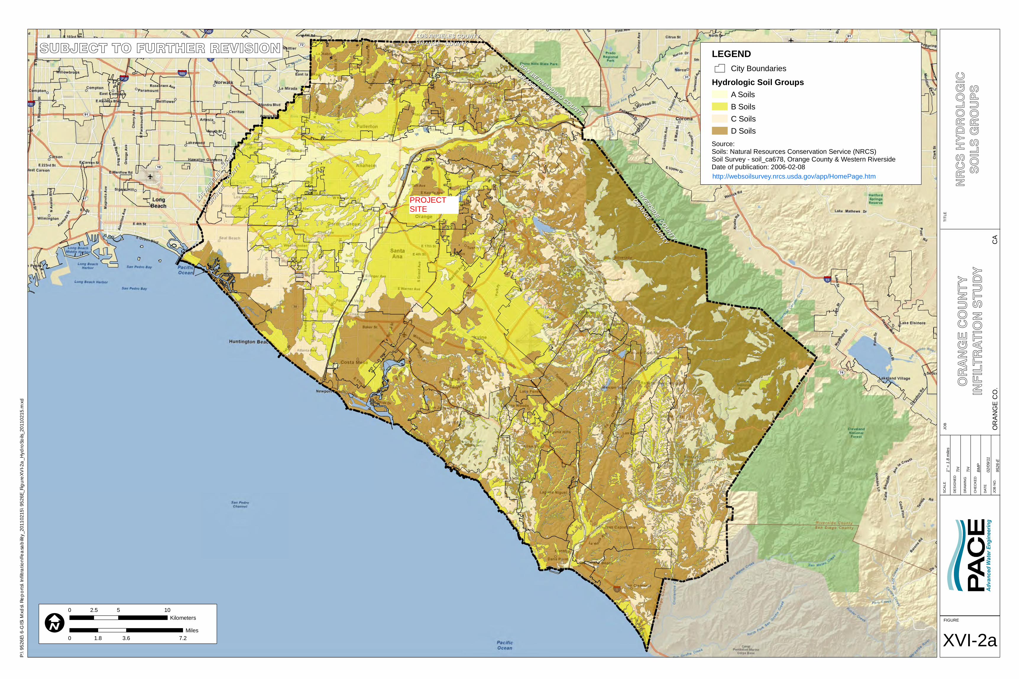
Predominant Soil Type Soil Type A
III.2 Site Characteristics
Site Characteristics
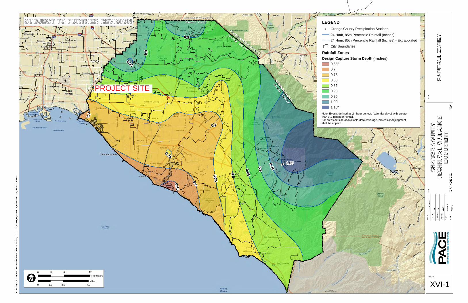
Precipitation Zone 0.80” (per OCTGD Figure XVI.1: Orange County Rainfall Zones
Map)
Topography
The site topography is relatively flat, sloping in the southwest
direction. The low point is in the south west corner of the site,
where there are two existing inlets.
Drainage
Patterns/Connections
The proposed site will drain to five bio-retention flow-through
planter treatment areas via roof drains and an on-site private
underground storm drain system. An existing storm drain
system serves the neighboring sites. All of the collected on-site
storm water will be treated in one of the five bioretention
planters and discharged to the gutter via underdrain pipes.
Soil Type, Geology, and
Infiltration Properties
The project site consists of type A soil. The site contains no
constraints to infiltration or overlapping constraints as defined
Water Quality Management Plan (WQMP)
ORANGE COUNTY JUVENILE HALL MULTIPURPOSE REHABILITATION CENTER
Error! Reference source not found. Section III Water Quality.docx Page 7
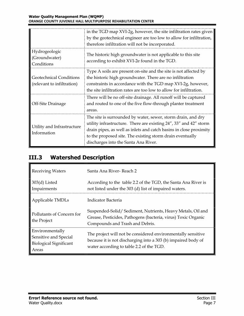
in the TGD map XVI-2g, however, the site infiltration rates given
by the geotechnical engineer are too low to allow for infiltration,
therefore infiltration will not be incorporated.
Hydrogeologic
(Groundwater)
Conditions
The historic high groundwater is not applicable to this site
according to exhibit XVI-2e found in the TGD.
Geotechnical Conditions
(relevant to infiltration)
Type A soils are present on-site and the site is not affected by
the historic high groundwater. There are no infiltration
constraints in accordance with the TGD map XVI-2g, however,
the site infiltration rates are too low to allow for infiltration.
Off-Site Drainage
There will be no off-site drainage. All runoff will be captured
and routed to one of the five flow-through planter treatment
areas.
Utility and Infrastructure
Information
The site is surrounded by water, sewer, storm drain, and dry
utility infrastructure. There are existing 24”, 33” and 42” storm
drain pipes, as well as inlets and catch basins in close proximity
to the proposed site. The existing storm drain eventually
discharges into the Santa Ana River.
III.3 Watershed Description
Receiving Waters Santa Ana River- Reach 2
303(d) Listed
Impairments
According to the table 2.2 of the TGD, the Santa Ana River is
not listed under the 303 (d) list of impaired waters.
Applicable TMDLs Indicator Bacteria
Pollutants of Concern for
the Project
Suspended-Solid/ Sediment, Nutrients, Heavy Metals, Oil and
Grease, Pesticides, Pathogens (bacteria, virus) Toxic Organic
Compounds and Trash and Debris.
Environmentally
Sensitive and Special
Biological Significant
Areas
The project will not be considered environmentally sensitive
because it is not discharging into a 303 (b) impaired body of
water according to table 2.2 of the TGD.

Water Quality Management Plan (WQMP)
ORANGE COUNTY JUVENILE HALL MULTIPURPOSE REHABILITATION CENTER
OC Juvenile Hall MRC Section IV
Water Quality.docx Page 8
Section IV Best Management Practices (BMPs)
IV. 1 Project Performance Criteria
(NOC Permit Area only) Is there an approved WIHMP or equivalent
for the project area that includes more stringent LID feasibility
criteria or if there are opportunities identified for implementing LID
on regional or sub-regional basis?
YES NO
If yes, describe WIHMP
feasibility criteria or
regional/sub-regional LID
opportunities.
Not Applicable.
Water Quality Management Plan (WQMP)
ORANGE COUNTY JUVENILE HALL MULTIPURPOSE REHABILITATION CENTER
OC Juvenile Hall MRC Section IV
Water Quality.docx Page 9
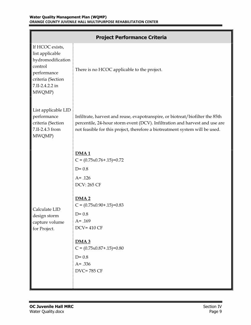
Project Performance Criteria
If HCOC exists,
list applicable
hydromodification
control
performance
criteria (Section
7.II-2.4.2.2 in
MWQMP)
There is no HCOC applicable to the project.
List applicable LID
performance
criteria (Section
7.II-2.4.3 from
MWQMP)
Infiltrate, harvest and reuse, evapotranspire, or biotreat/biofilter the 85th
percentile, 24-hour storm event (DCV). Infiltration and harvest and use are
not feasible for this project, therefore a biotreatment system will be used.
Calculate LID
design storm
capture volume
for Project.
DMA 1
C = (0.75x0.76+.15)=0.72
D= 0.8
A= .126
DCV: 265 CF
DMA 2
C = (0.75x0.90+.15)=0.83
D= 0.8
A= .169
DCV= 410 CF
DMA 3
C = (0.75x0.87+.15)=0.80
D= 0.8
A= .336
DVC= 785 CF
Water Quality Management Plan (WQMP)
ORANGE COUNTY JUVENILE HALL MULTIPURPOSE REHABILITATION CENTER
OC Juvenile Hall MRC Section IV
Water Quality.docx Page 10
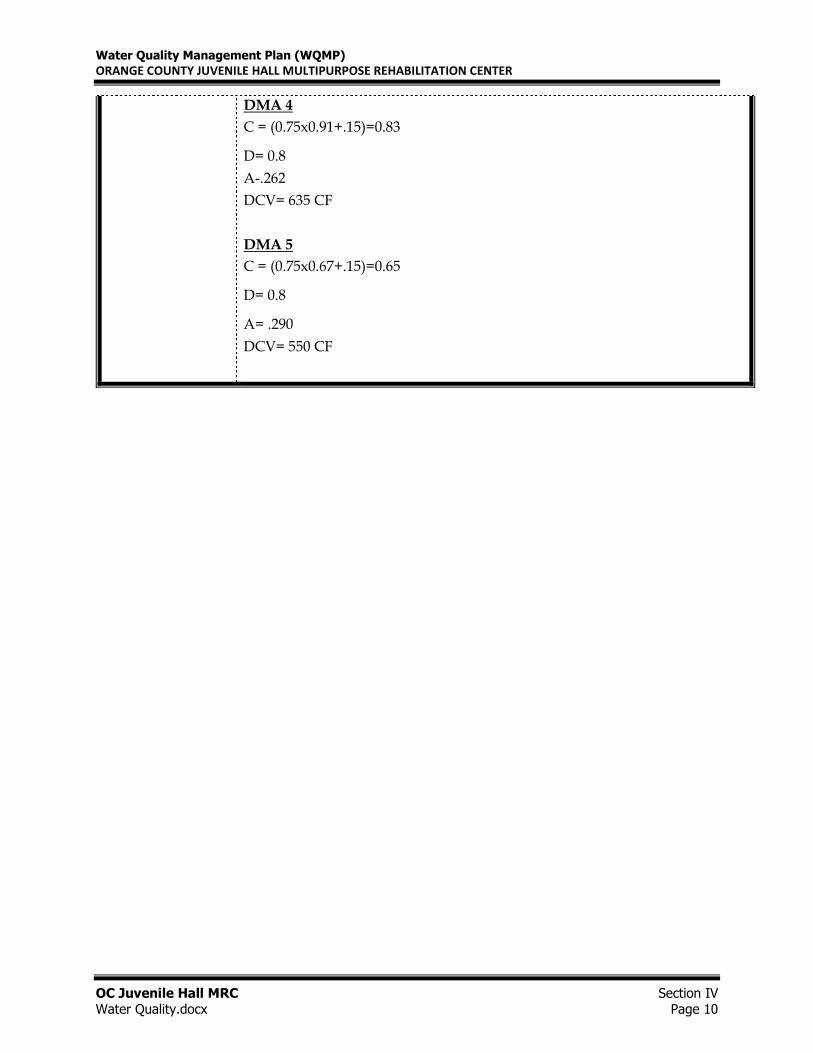
DMA 4
C = (0.75x0.91+.15)=0.83
D= 0.8
A-.262
DCV= 635 CF
DMA 5
C = (0.75x0.67+.15)=0.65
D= 0.8
A= .290
DCV= 550 CF
Water Quality Management Plan (WQMP)
ORANGE COUNTY JUVENILE HALL MULTIPURPOSE REHABILITATION CENTER
OC Juvenile Hall MRC Section IV
Water Quality.docx Page 11
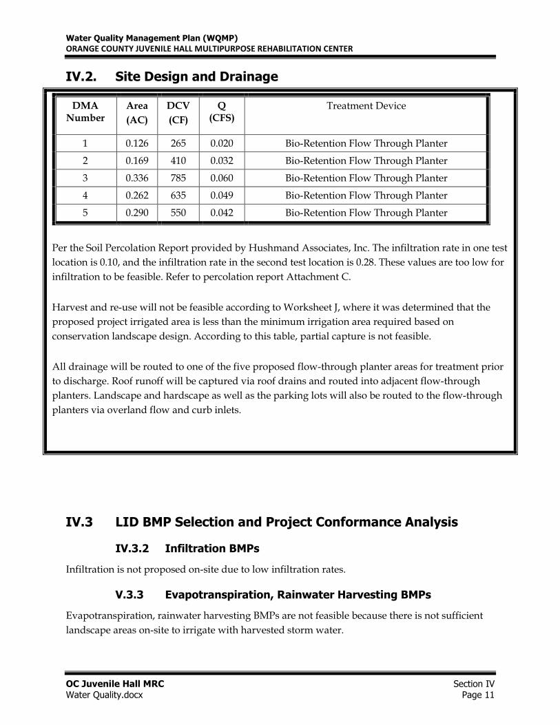
IV.2. Site Design and Drainage
DMA Number
Area
(AC)
DCV
(CF)
Q (CFS)
Treatment Device
1 0.126 265 0.020 Bio-Retention Flow Through Planter
2 0.169 410 0.032 Bio-Retention Flow Through Planter
3 0.336 785 0.060 Bio-Retention Flow Through Planter
4 0.262 635 0.049 Bio-Retention Flow Through Planter
5 0.290 550 0.042 Bio-Retention Flow Through Planter
Per the Soil Percolation Report provided by Hushmand Associates, Inc. The infiltration rate in one test
location is 0.10, and the infiltration rate in the second test location is 0.28. These values are too low for
infiltration to be feasible. Refer to percolation report Attachment C.
Harvest and re-use will not be feasible according to Worksheet J, where it was determined that the
proposed project irrigated area is less than the minimum irrigation area required based on
conservation landscape design. According to this table, partial capture is not feasible.
All drainage will be routed to one of the five proposed flow-through planter areas for treatment prior
to discharge. Roof runoff will be captured via roof drains and routed into adjacent flow-through
planters. Landscape and hardscape as well as the parking lots will also be routed to the flow-through
planters via overland flow and curb inlets.
IV.3 LID BMP Selection and Project Conformance Analysis
IV.3.2 Infiltration BMPs
Infiltration is not proposed on-site due to low infiltration rates.
V.3.3 Evapotranspiration, Rainwater Harvesting BMPs
Evapotranspiration, rainwater harvesting BMPs are not feasible because there is not sufficient
landscape areas on-site to irrigate with harvested storm water.
Water Quality Management Plan (WQMP)
ORANGE COUNTY JUVENILE HALL MULTIPURPOSE REHABILITATION CENTER
OC Juvenile Hall MRC Section IV
Water Quality.docx Page 12
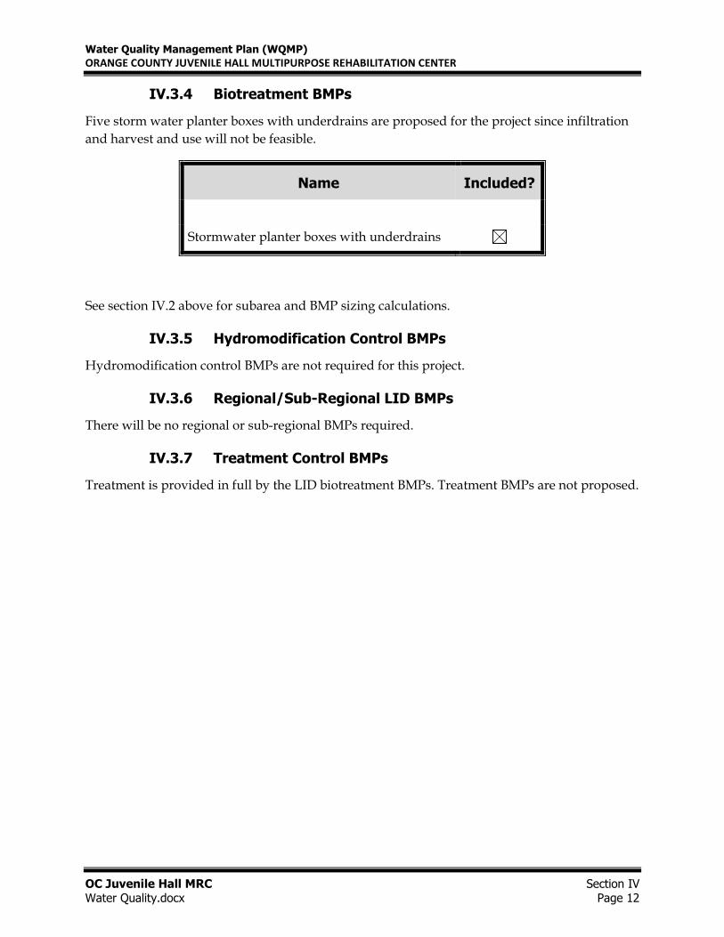
IV.3.4 Biotreatment BMPs
Five storm water planter boxes with underdrains are proposed for the project since infiltration
and harvest and use will not be feasible.
Name Included?
Stormwater planter boxes with underdrains
See section IV.2 above for subarea and BMP sizing calculations.
IV.3.5 Hydromodification Control BMPs
Hydromodification control BMPs are not required for this project.
IV.3.6 Regional/Sub-Regional LID BMPs
There will be no regional or sub-regional BMPs required.
IV.3.7 Treatment Control BMPs
Treatment is provided in full by the LID biotreatment BMPs. Treatment BMPs are not proposed.
Water Quality Management Plan (WQMP)
ORANGE COUNTY JUVENILE HALL MULTIPURPOSE REHABILITATION CENTER
OC Juvenile Hall MRC Section IV
Water Quality.docx Page 13
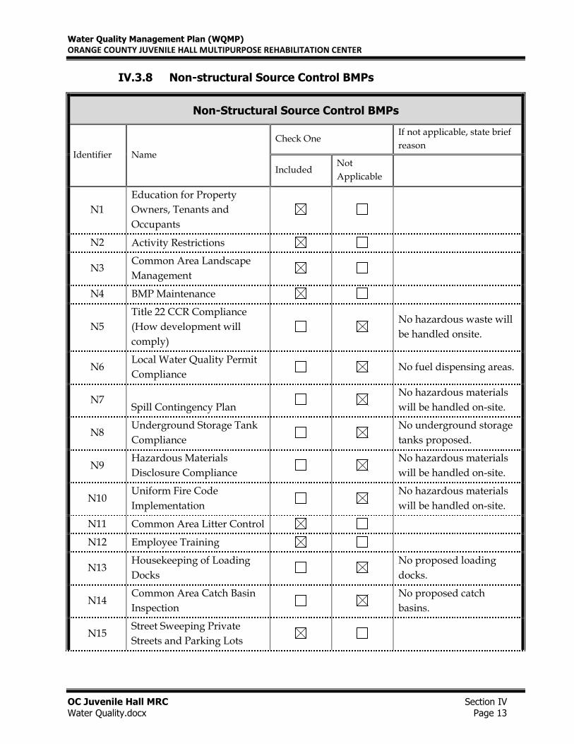
IV.3.8 Non-structural Source Control BMPs
Non-Structural Source Control BMPs
Identifier Name
Check One If not applicable, state brief
reason
Included Not
Applicable
N1
Education for Property
Owners, Tenants and
Occupants
N2 Activity Restrictions
N3 Common Area Landscape
Management
N4 BMP Maintenance
N5
Title 22 CCR Compliance
(How development will
comply)
No hazardous waste will
be handled onsite.
N6 Local Water Quality Permit
Compliance No fuel dispensing areas.
N7 Spill Contingency Plan
No hazardous materials
will be handled on-site.
N8 Underground Storage Tank
Compliance
No underground storage
tanks proposed.
N9 Hazardous Materials
Disclosure Compliance
No hazardous materials
will be handled on-site.
N10 Uniform Fire Code
Implementation
No hazardous materials
will be handled on-site.
N11 Common Area Litter Control
N12 Employee Training
N13 Housekeeping of Loading
Docks
No proposed loading
docks.
N14 Common Area Catch Basin
Inspection
No proposed catch
basins.
N15 Street Sweeping Private
Streets and Parking Lots
Water Quality Management Plan (WQMP)
ORANGE COUNTY JUVENILE HALL MULTIPURPOSE REHABILITATION CENTER
OC Juvenile Hall MRC Section IV
Water Quality.docx Page 14
N16 Retail Gasoline Outlets No proposed fueling stations.
Implementation of Non-Structural BMPS
N1. Education of Property Owners, Tenants and Occupants.
Responsible Party for Implementation of BMP: Orange County Public Works
Implementation Frequency: Ongoing. Orientation shall be given to new owners, tenants, and
occupants within 30 days of startup.
Educational material and information shall be provided by the property owner to new owners
and staff on general good housekeeping BMPs and other practices that contribute to protection of
storm water quality. This WQMP shall be provided with emphasis placed on the materials
included in, but not limited to, Sections V, VI and VII of this report. For additional information,
see the BMP Maintenance Responsibility /Frequency Matrix in Section V. In addition to the
attachments, the following resource can be contacted to obtain updated educational information
free of charge http://ocwatersheds.com/PublicEd. See Table V-1 in Section V for inspection and
maintenance activity requirements.
N2. Activity Restrictions.
Responsible Party for Implementation of BMP: Orange County Public Works
Implementation Frequency: Daily management of operation.
Parking restrictions include, but are not limited to, provisions regulating vehicle and truck
deliveries, vehicle and truck parking, loading and unloading activities, etc. Some other common
restrictions to be adhered to are as follows:
• No discharges of fertilizer, pesticides, and wastes to streets or storm drains
• No blowing or sweeping of debris into streets or storm drains
• No hosing down of paved surfaces
• No vehicle washing or maintenance.
• Do not perform paint cleanup activities in paved areas or allow rinse water from these
activities to enter the storm drain system. Clean brushes containing water-based paint in a
sink that is connected to the sanitary sewer system.
• Do not use detergents or other chemical additives when washing concrete sidewalks or
building exteriors, use potable water only and collect wash water runoff using a
vacuum truck, for proper offsite disposal.
• Keep premises, as well as trash container areas, free of litter. See Table V -1 in Section V
for inspection and maintenance activity requirements.
Water Quality Management Plan (WQMP)
ORANGE COUNTY JUVENILE HALL MULTIPURPOSE REHABILITATION CENTER
OC Juvenile Hall MRC Section IV
Water Quality.docx Page 15
In addition, onsite activities shall be limited to the requirements of this WQMP as described herein.
N3. Common Area Landscape Management.
Responsible Party for Implementation of BMP: Orange County Public Works
Implementation Frequency: Landscape areas shall be maintained on a weekly basis.
Maintenance shall include plant vegetation that reduces water, fertilizer, herbicide, and pesticide
use. Waste shall be disposed of by composting or at a permitted landfill and shall not be raked or
blown into the street, gutter, or storm drains. Irrigation systems shall be inspected monthly for
leaks. Leaks shall be repaired as soon as they are observed. Avoid over-watering of vegetation. If
excessive runoff is observed, automatic timers shall be adjusted. Fertilizers, herbicides, and
pesticides shall be used as directed on the label. If fertilizer is spilled on a paved surface it should
be swept up immediately and placed in its container. Water shall not be used to clean fertilizer
spills unless necessary and only after the area has been thoroughly cleaned using dry
cleaning methods.
N4. BMP Maintenance.
Responsible Party for Implementation of BMP: Orange County Public Works
Implementation Frequency: Individual BMPs shall be inspected based on the required frequency of
each BMP as suggested in the Maintenance Responsibility /Frequency Matrix. See the BMP
Maintenance Responsibility /Frequency Matrix in Section V for details.
N11. Common Area Litter Control
Responsible Party for Implementation of BMP: Orange County Public Works
Implementation Frequency: On a weekly basis through a maintenance firm.
In order to reduce the likelihood of polluting storm water runoff, regular maintenance will be
conducted. This will consist of, at a minimum, site-wide litter control, emptying of trash receptacles
in common areas, sweeping of dumpster enclosure areas, and reporting trash disposal violations to
the owner or POA for investigation. The landscape maintenance may be contracted for common
area litter control as well. See Table V-1 in Section V for inspection and maintenance activity
requirements. Trash enclosures will include roofs.
Water Quality Management Plan (WQMP)
ORANGE COUNTY JUVENILE HALL MULTIPURPOSE REHABILITATION CENTER
OC Juvenile Hall MRC Section IV
Water Quality.docx Page 16
N12. Employee Training
Responsible Party for Implementation of BMP: Orange County Public Works
Implementation Frequency: Education of applicable employees shall continue on an ongoing basis
and shall be done within 30 days of startup. Each new applicable onsite employee shall be given a
water quality orientation within 30 days of hire using this WQMP Report as a reference. At a
minimum, each applicable onsite employee shall have an annual review of the provisions of the
WQMP Report for this project
See Table V -1 in Section V for inspection and maintenance activity requirements.
N15. Street Sweeping Private Streets and Parking Lots.
Responsible Party for Implementation of BMP: Orange County Public Works
Implementation Frequency: Twice a month to remove debris.
The owner shall be responsible for sweeping the surrounding parking lot on a regular basis to
remove debris. At minimum, the streets and parking lots will be required to be swept prior to the
storm season, in late summer or early fall, prior to the start of the rainy season, or equivalent as
required by the governing jurisdiction. For additional information, see BMP SC-34, Waste Handling
and· Disposal and BMP SC-43, Parking/Storage Area Maintenance, included in Section VII, and the
BMP Maintenance Responsibility /Frequency Matrix in Section V.
Water Quality Management Plan (WQMP)
ORANGE COUNTY JUVENILE HALL MULTIPURPOSE REHABILITATION CENTER
OC Juvenile Hall MRC Section IV
Water Quality.docx Page 17
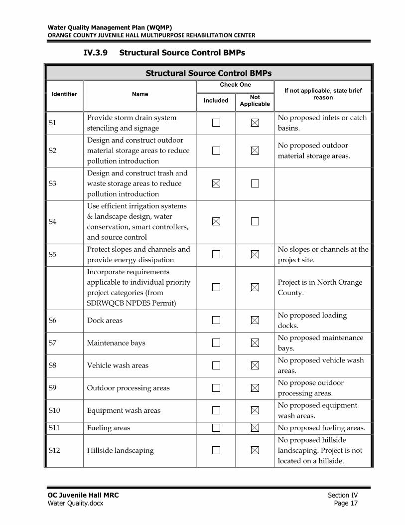
IV.3.9 Structural Source Control BMPs
Structural Source Control BMPs
Identifier Name
Check One If not applicable, state brief
reason Included
Not Applicable
S1 Provide storm drain system
stenciling and signage
No proposed inlets or catch
basins.
S2
Design and construct outdoor
material storage areas to reduce
pollution introduction
No proposed outdoor
material storage areas.
S3
Design and construct trash and
waste storage areas to reduce
pollution introduction
S4
Use efficient irrigation systems
& landscape design, water
conservation, smart controllers,
and source control
S5 Protect slopes and channels and
provide energy dissipation
No slopes or channels at the
project site.
Incorporate requirements
applicable to individual priority
project categories (from
SDRWQCB NPDES Permit)
Project is in North Orange
County.
S6 Dock areas No proposed loading
docks.
S7 Maintenance bays No proposed maintenance
bays.
S8 Vehicle wash areas No proposed vehicle wash
areas.
S9 Outdoor processing areas No propose outdoor
processing areas.
S10 Equipment wash areas No proposed equipment
wash areas.
S11 Fueling areas No proposed fueling areas.
S12 Hillside landscaping
No proposed hillside
landscaping. Project is not
located on a hillside.
Water Quality Management Plan (WQMP)
ORANGE COUNTY JUVENILE HALL MULTIPURPOSE REHABILITATION CENTER
OC Juvenile Hall MRC Section IV
Water Quality.docx Page 18
S13 Wash water control for food
preparation areas
No proposed food
preparation areas on-site.
S14 Community car wash racks No proposed community
car wash racks.
Implementation of Structural BMPs
S3. Design and construct trash and waste storage areas
Responsible Party: Orange County Public Works
Maintenance Implementation Frequency: Loose trash will be picked up daily and placed in
containers. Trash dumpster pickup shall be a minimum of once a week.
The trash storage areas will be paved with an impervious surface. No drainage will be directed
towards the trash areas. For additional information, see BMP SD-32, Trash Storage Areas, in Section
VII and the BMP Maintenance Responsibility /Frequency Matrix in Section V.
S4. Use efficient irrigation systems & landscape design
Responsible Party: Orange County Public Works
Implementation Frequency: Inspect irrigation equipment on a monthly basis. Check water sensors
and adjust irrigation heads and timing monthly.
The proposed landscape and irrigation system shall group plants with similar water requirements
in order to reduce excess irrigation runoff. Rain shutoff devices shall be used to prevent irrigation
after precipitation. Monthly inspection of the irrigation system shall be conducted to insure efficient
water uses. See BMPs SC-41, Building and Grounds Maintenance, SD-10~ Site Design and
Landscape Planning, and SD-12, Efficient Irrigation, in Section VII. Also refer to the BMP
Maintenance Responsibility /Frequency Matrix in Section V.
Water Quality Management Plan (WQMP)
ORANGE COUNTY JUVENILE HALL MULTIPURPOSE REHABILITATION CENTER
OC Juvenile Hall MRC Section IV
Water Quality.docx Page 19
IV.4 Alternative Compliance Plan (If Applicable)
An alternative compliance plan is not being pursued for this project.
Water Quality Management Plan (WQMP)
ORANGE COUNTY JUVENILE HALL MULTIPURPOSE REHABILITATION CENTER
OC Juvenile Hall MRC Section V
Water Quality.docx Page 20
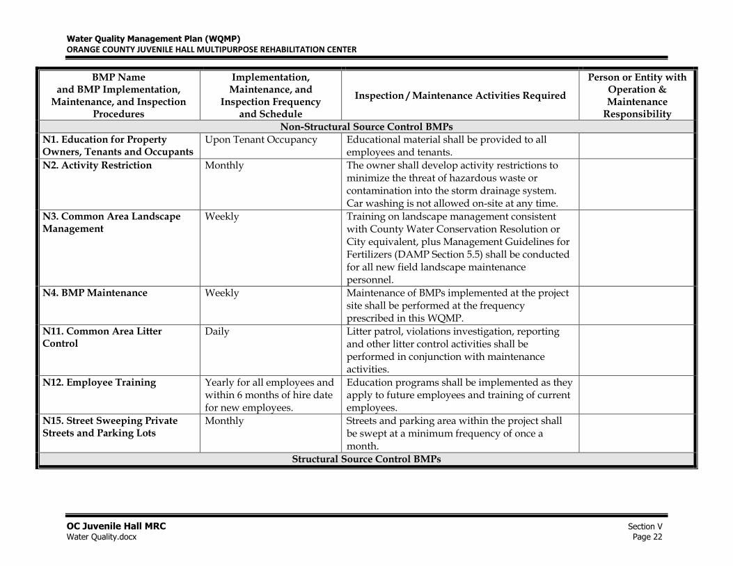
Section V Inspection/Maintenance Responsibility for BMPs
The following tables indicate BMP inspection and maintenance responsibility. These tables identify
the party responsible for inspection and maintenance, a description of the inspection and/or
maintenance activity, and a frequency for the inspection and/or maintenance activity. Records of
maintenance and inspections shall be kept for a period of five years and shall be made available for
review by government agencies.
The County of Orange (property owner) shall delegate an individual or individuals to take direct
responsibility for the operations and maintenance (O&M) of the BMP devices described in this
report.
The responsible parties shall be responsible for the following:
• Being designated contacts with County inspectors to sign self-inspection reports and
any correspondence regarding verification inspections.
• Coordination with emplyees or contractors responsible for conducting stormwater
BMP operation and maintenance activities.
• Handling and negotiating any contracts that might be necessary for future changes
to operation and maintenance or for remedial measures as a result of BMP issues.
• Serving as an emergency contact & responder for problems with the BMP such as
clogged drains or other damages that would stop the performance of the BMP. These
responsibilities apply regardless if there events occur during off-hours.
Updated contract information shall be provided to the County immediately whenever a property is
sold or whenever responsible parties or contractors change. An organizational chart shall be
provided to prevent loss of contact or miscommunication.
Water Quality Management Plan (WQMP)
ORANGE COUNTY JUVENILE HALL MULTIPURPOSE REHABILITATION CENTER
OC Juvenile Hall MRC Section V
Water Quality.docx Page 21
Responsible party details as indicated in the table are as folows:
Owner/Property Management Company
Name: William Dube
Title: Senior Project Manager
Company: Orange County Public Works
Address: 300 N. Flower Street, Santa Ana, CA 92703
Phone Number: 714-667-4926
Water Quality Management Plan (WQMP)
ORANGE COUNTY JUVENILE HALL MULTIPURPOSE REHABILITATION CENTER
OC Juvenile Hall MRC Section V
Water Quality.docx Page 22
BMP Name and BMP Implementation,
Maintenance, and Inspection Procedures
Implementation, Maintenance, and
Inspection Frequency and Schedule
Inspection / Maintenance Activities Required
Person or Entity with Operation & Maintenance
Responsibility
Non-Structural Source Control BMPs
N1. Education for Property Owners, Tenants and Occupants
Upon Tenant Occupancy Educational material shall be provided to all employees and tenants.
N2. Activity Restriction
Monthly The owner shall develop activity restrictions to minimize the threat of hazardous waste or contamination into the storm drainage system. Car washing is not allowed on-site at any time.
N3. Common Area Landscape Management
Weekly Training on landscape management consistent with County Water Conservation Resolution or City equivalent, plus Management Guidelines for Fertilizers (DAMP Section 5.5) shall be conducted for all new field landscape maintenance personnel.
N4. BMP Maintenance
Weekly Maintenance of BMPs implemented at the project site shall be performed at the frequency prescribed in this WQMP.
N11. Common Area Litter Control
Daily Litter patrol, violations investigation, reporting and other litter control activities shall be performed in conjunction with maintenance activities.
N12. Employee Training
Yearly for all employees and within 6 months of hire date for new employees.
Education programs shall be implemented as they apply to future employees and training of current employees.
N15. Street Sweeping Private Streets and Parking Lots
Monthly Streets and parking area within the project shall be swept at a minimum frequency of once a month.
Structural Source Control BMPs
Water Quality Management Plan (WQMP)
ORANGE COUNTY JUVENILE HALL MULTIPURPOSE REHABILITATION CENTER
OC Juvenile Hall MRC Section V
Water Quality.docx Page 23
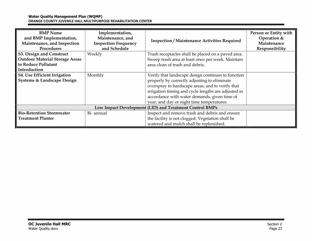
BMP Name and BMP Implementation,
Maintenance, and Inspection Procedures
Implementation, Maintenance, and
Inspection Frequency and Schedule
Inspection / Maintenance Activities Required
Person or Entity with Operation & Maintenance
Responsibility
S3. Design and Construct Outdoor Material Storage Areas to Reduce Pollutant Introduction
Weekly Trash receptacles shall be placed on a paved area. Sweep trash area at least once per week. Maintain area clean of trash and debris.
S4. Use Efficient Irrigation Systems & Landscape Design
Monthly Verify that landscape design continues to function properly by correctly adjusting to eliminate overspray to hardscape areas, and to verify that irrigation timing and cycle lengths are adjusted in accordance with water demands, given time of year, and day or night time temperatures.
Low Impact Development (LID) and Treatment Control BMPs Bio-Retention Stormwater Treatment Planter
Bi- annual Inspect and remove trash and debris and ensure the facility is not clogged. Vegetation shall be watered and mulch shall be replenished.
Water Quality Management Plan (WQMP)
ORANGE COUNTY JUVENILE HALL MULTIPURPOSE REHABILITATION CENTER
OC Juvenile Hall MRC Section VI Water Quality.docx Page 24
Section VI BMP Exhibit (Site Plan)
VI.1 BMP Exhibit (Site Plan)
See attachment H for the WQMP site plan.
VI.2 Submittal and Recordation of Water Quality Management
Plan
A PDF of the full report is included with the submittal.
G
Water Quality Management Plan (WQMP)
ORANGE COUNTY JUVENILE HALL MULTIPURPOSE REHABILITATION CENTER
OC Juvenile Hall MRC Section VII Water Quality.docx Page 25
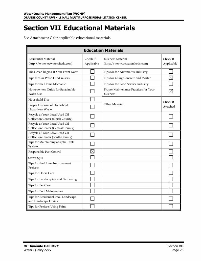
Section VII Educational Materials
See Attachment C for applicable educational materials.
Education Materials
Residential Material
(http://www.ocwatersheds.com)
Check If
Applicable
Business Material
(http://www.ocwatersheds.com)
Check If
Applicable
The Ocean Begins at Your Front Door Tips for the Automotive Industry
Tips for Car Wash Fund-raisers Tips for Using Concrete and Mortar
Tips for the Home Mechanic Tips for the Food Service Industry
Homeowners Guide for Sustainable
Water Use
Proper Maintenance Practices for Your
Business
Household Tips
Other Material Check If
Attached Proper Disposal of Household
Hazardous Waste
Recycle at Your Local Used Oil
Collection Center (North County)
Recycle at Your Local Used Oil
Collection Center (Central County)
Recycle at Your Local Used Oil
Collection Center (South County)
Tips for Maintaining a Septic Tank
System
Responsible Pest Control
Sewer Spill
Tips for the Home Improvement
Projects
Tips for Horse Care
Tips for Landscaping and Gardening
Tips for Pet Care
Tips for Pool Maintenance
Tips for Residential Pool, Landscape
and Hardscape Drains
Tips for Projects Using Paint
ATTACHMENT A
303d LIST OF IMPAIRED WATER BODIES
TECHNICAL GUIDANCE DOCUMENT
2-18 December 20, 2013
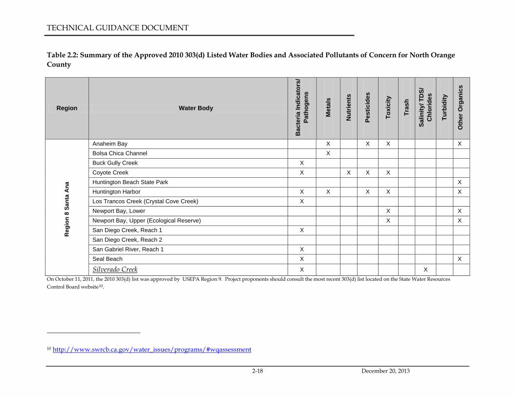
Table 2.2: Summary of the Approved 2010 303(d) Listed Water Bodies and Associated Pollutants of Concern for North Orange County
Region Water Body
Bac
teria
Indi
cato
rs/
Path
ogen
s
Met
als
Nut
rient
s
Pest
icid
es
Toxi
city
Tras
h
Salin
ity/ T
DS/
C
hlor
ides
Turb
idity
Oth
er O
rgan
ics
Reg
ion
8 Sa
nta
Ana
Anaheim Bay X X X X Bolsa Chica Channel X Buck Gully Creek X Coyote Creek X X X X Huntington Beach State Park X Huntington Harbor X X X X X Los Trancos Creek (Crystal Cove Creek) X Newport Bay, Lower X X Newport Bay, Upper (Ecological Reserve) X X San Diego Creek, Reach 1 X San Diego Creek, Reach 2 San Gabriel River, Reach 1 X Seal Beach X X
Silverado Creek X X On October 11, 2011, the 2010 303(d) list was approved by USEPA Region 9. Project proponents should consult the most recent 303(d) list located on the State Water Resources Control Board website10.
10 http://www.swrcb.ca.gov/water_issues/programs/#wqassessment

ATTACHMENT B
COUNTY SOILS AND RAINFALL MAPS
ORANGE COUNTY
ORANGE COUNTY
RIVERSIDE COUNTY
RIVERSIDE COUNTY
ORANGE COUNTY
ORANGE COUNTY
SAN BERNARDINO COUNTY
SAN BERNARDINO COUNTY
ORANGE COUNTYORANGE COUNTYLOS ANGELES COUNTYLOS ANGELES COUNTY
ORANGE COUNTY
ORANGE COUNTY
LOS A
NGELES
COUNTY
LOS A
NGELES
COUNTY
P:\95
26E\
6-GIS\
Mxds
\Rep
orts\
Infiltr
ation
Feas
ability
_201
1021
5\95
26E_
Figure
XVI-2
a_Hy
droS
oils_2
0110
215.m
xd
FIGURE
XVI-2a
JOB
TITL
ES
CA
LE1"
= 1.8
miles
DE
SIG
NE
D
DR
AWIN
G
CH
EC
KE
DBM
P02
/09/11
DAT
E
JOB
NO
.95
26-E
THTHOR
ANGE
COUN
TYINF
ILTRA
TION S
TUDY
OR
AN
GE
CO
.C
A
NRCS
HYDR
OLOG
ICSO
ILS GR
OUPS
SUBJECT TO FURTHER REVISION
Source: Soils: Natural Resources Conservation Service (NRCS)Soil Survey - soil_ca678, Orange County & Western RiversideDate of publication: 2006-02-08
!I0 3.6 7.21.8
Miles
0 5 102.5Kilometers
LEGENDCity Boundaries
Hydrologic Soil GroupsA SoilsB SoilsC SoilsD Soils
http://websoilsurvey.nrcs.usda.gov/app/HomePage.htm
PROJECTSITE
ORANGE COUNTYORANGE COUNTY
LOS ANGELES COUNTYLOS ANGELES COUNTY
1.05
0.7
FIGURE
SUBJECT TO FURTHER REVISION
0 3.6 7.21.8Miles
0 6 123Kilometers
LEGENDOrange County Precipitation Stations
24 Hour, 85th Percentile Rainfall (Inches)24 Hour, 85th Percentile Rainfall (Inches) - Extrapolated
City Boundaries
Rainfall ZonesDesign Capture Storm Depth (inches)
0.65"0.70.750.800.850.900.951.001.10"
Note: Events defined as 24-hour periods (calendar days) with greaterthan 0.1 inches of rainfall.For areas outside of available data coverage, professional judgmentshall be applied.
XVI-1
PROJECT SITE
P:\95
26E\
6-GIS\
Mxds
\Suc
epta
bility
Maps
_201
0050
5\95
26E_
Santa
AnaR
iverSu
scep
tibility
_201
0043
0.mxd
ClevelandNational Forest
San BernardinoCounty
Riverside County
South OrangeCounty
Newport BayWatershed
Stabilized byGrade Control
Structure
San Gabriel-Coyote CreekWatershed
Anaheim Bay-Huntington Harbor
Watershed
PetersCanyon
Reservoir
OliveHills
KraemerBasin
CarbonCanyon
WalnutCanyon
Reservoir
IrvineLake
AnaheimLake
WarnerBasin
MillerRetarding
Basin
BartlettRetarding
Basin
FletcherRetarding
Basin
SOUTHPARKPUMP
STATION
VillaPark Dam
Yorba LindaReservoir
Sources: Esri, DeLorme, NAVTEQ, USGS, Intermap, iPC, NRCAN, Esri Japan, METI, Esri China (Hong Kong), Esri (Thailand), TomTom, 2012
FIGURE
3
JOB
TITL
ESC
ALE
1" = 1
2000
'D
ES
IGN
ED
DR
AW
ING
CH
EC
KE
DBM
P
04/30
/10D
ATE
JOB
NO
.95
26-E
THTHOR
ANGE
COUN
TYWA
TERS
HED
MAST
ER PL
ANNIN
GO
RA
NG
E C
O.
CA
SUSC
EPTIB
ILITY A
NALYI
SSA
NTA A
NA RI
VER
!I 0 12,000 24,000Feet
SusceptibilityPotential Areas of Erosion, Habitat, &Physical Structure Susceptibility
Channel TypeEarth (Unstable)
Earth (Stabilized)
Stabilized
Tidel Influence<= Mean High Water Line (4.28')
Water BodyBasin
Dam
Lake
Reservoir
Forest AreasCleveland National Forest
Federal LandsAmarus Salt Marsh
Sources: Esri, DeLorme, NAVTEQ,USGS, Intermap, iPC, NRCAN, EsriJapan, METI, Esri China (HongKong), Esri (Thailand), TomTom,2012
SUSCEPTIBILITY MAP UPATE (FEB 2013)
PROJECT SITE

ATTACHMENT C
GEOTECHNICAL REPORT
GEOTECHNICAL PROFESSIONAL SERVICES PROPOSED MULTIPURPOSE BUILDING SITE FOR
JUVENILE HALL, CITY OF ORANGE, ORANGE COUNTY, CALIFORNIA
Prepared for
VA Consulting, Inc. 46 Discovery, Suite 250
Irvine, California 92618
Prepared by
Hushmand Associates, Inc. 250 Goddard
Irvine, California 92618 [email protected] (949) 777-1266
August 2015
Page i VAC-15-001
TABLE OF CONTENTS
Page
1.0 INTRODUCTION ........................................................................................................................... 1
1.1 Project Description and Background ........................................................................................ 1
1.2 Purpose and Scope of Services ................................................................................................... 1
2.0 FIELD EXPLORATION AND LABORATORY TESTING ...................................................... 2
2.1 FIELD EXPLORATIONS ......................................................................................................... 2
2.1.1 Geophysical Testing .............................................................................................................. 2
2.1.2 Cone Penetration Test (CPT) Soundings .............................................................................. 2
2.1.3 Hollow Stem Auger Drilling ................................................................................................. 3
2.2 LABORATORY TESTING ....................................................................................................... 4
3.0 GEOLOGY AND SITE CONDITIONS ....................................................................................... 4
3.1 REGIONAL GEOLOGY ........................................................................................................... 4
3.2 LOCAL GEOLOGY ................................................................................................................... 4
3.3 SUBSURFACE CONDITIONS ................................................................................................. 5
3.4 GROUNDWATER ...................................................................................................................... 6
4.0 SEISMICITY AND SEISMIC HAZARDS EVALUATION ....................................................... 6
4.1 REGIONAL FAULTS ................................................................................................................ 6
4.2 SEISMIC HAZARDS AND DESIGN PARAMETERS CONSIDERATION ....................... 9
4.2.1 Fault Related Ground Rupture .............................................................................................. 9
4.2.2 Ground Shaking .................................................................................................................... 9
4.2.3 Seismic Design Considerations ........................................................................................... 10
4.2.4 Liquefaction Potential ......................................................................................................... 10
4.2.5 Earthquake Induced Lateral Spreading and Flow Failure ................................................... 11
4.2.6 Earthquake-Induced Settlement .......................................................................................... 11
4.2.7 Landslides ........................................................................................................................... 12
4.2.8 Ground Lurching ................................................................................................................. 12
4.2.9 Flooding Tsunamis and Seiches .......................................................................................... 12
Page ii VAC-15-001
5.0 FINDINGS AND CONCLUSIONS ............................................................................................. 13
5.1 GENERAL ................................................................................................................................. 13
5.2 EFFECT OF PROPOSED CONSTRUCTION ON ADJACENT PROPERTIES .............. 13
5.3 PRIMARY GEOTECHNICAL CONCERNS ........................................................................ 13
5.4 SOIL EXPANSION POTENTIAL .......................................................................................... 13
6.0 RECOMMENDATIONS .............................................................................................................. 14
6.1 EARTHWORK ......................................................................................................................... 14
6.1.1 Clearing and Site Preparation ............................................................................................. 14
6.1.2 Over-excavation and Foundation Preparation ..................................................................... 14
6.1.3 Abandoned Utilities ............................................................................................................ 14
6.1.4 Subgrade Preparation .......................................................................................................... 14
6.1.5 Materials for Engineered Fill .............................................................................................. 14
6.1.6 Fill Placement and Compaction .......................................................................................... 15
6.1.7 Temporary Excavation ........................................................................................................ 15
6.1.8 Wet Weather Conditions ..................................................................................................... 15
6.2 POST-GRADING CONSIDERATIONS ................................................................................ 15
6.2.1 Surface Drainage ................................................................................................................. 15
6.2.2 Utility Trench Backfill ........................................................................................................ 16
6.3 FOUNDATIONS ....................................................................................................................... 16
6.3.1 Geogrid Reinforced Fills ..................................................................................................... 16
6.3.2 Spread Footings/ Continuous Footings ............................................................................... 18
6.3.3 Slab-on-Grade ..................................................................................................................... 18
6.4 SOLUBLE SULFATE AND GENERAL CORROSIVITY .................................................. 19
6.5 DISPOSAL OF CONTAMINATED SOIL ............................................................................. 20
7.0 ADDITIONAL SERVICES .......................................................................................................... 20
7.1 REVIEW OF CONSTRUCTION PLANS AND SPECIFICATIONS ................................. 20
7.2 GEOTECHNICAL OBSERVATION AND TESTING ......................................................... 20
8.0 LIMITATIONS ............................................................................................................................. 20
9.0 REFERENCES .............................................................................................................................. 21
Page iii VAC-15-001
LIST OF TABLES
Table 1 Summary of CPT Testing Table 2 Summary of Hollow Stem Auger Drilling Table 3 Summary of Closest Faults Table 4 2013 CBC Site Categorization and Site Coefficients Table 5 Results of Corrosivity Testing Table 6 Braced Temporary Shoring System Design Parameters LIST OF FIGURES Figure 1 Site Vicinity Map Figure 2 Preferred and Alternate Project Locations Figure 3 Approximate Boring and CPT Locations Map Figure 4 Geology Map Figure 5a Soil Property Characterization Data Vs Depth - Preferred Site Figure 5b Soil Property Characterization Data Vs Depth - Alternate Site Figure 6 2012 Groundwater Elevation Contour – County of Orange Figure 7 Historic High Groundwater Map – Anaheim Quadrangle Figure 8 Fault Activity Map Figure 9 Seismic Hazard Zone Map – Anaheim Quadrangle LIST OF APPENDICES Appendix A Logs of CPT Appendix B Logs of Exploratory Borings Appendix C Laboratory Test Results Appendix D USGS Seismic Design Parameters Appendix E Liquefaction Analyses Appendix F Geogrid Reinforced Subgrade
Page 1 VAC-15-001
GEOTECHNICAL PROFESSIONAL SERVICES PROPOSED MULTIPURPOSE BUILDING SITE FOR
JUVENILE HALL, CITY OF ORANGE, ORANGE COUNTY, CALIFORNIA
1.0 INTRODUCTION
1.1 Project Description and Background
The proposed project consists of constructing a 25,000 square feet (SF) Multi-Purpose Building (MRC) within the Orange County Juvenile Hall Campus (Figure 1). The MRC includes a visitation center, gymnasium, multipurpose rooms, treatment rooms, and support facilities. Two (2) locations within the existing campus are being considered as for the proposed building site. The preferred location is on an existing baseball field (preferred site) in close proximity to the Santa Ana River. The alternate location is on the Northwest corner of the campus (alternate site) on land that is currently occupied by four (4) existing housing units (Buildings R, S, O, M, and classrooms 19 and 20). The preferred location will occupy a footprint of between 41,232 SF and 60,000 SF, while the alternate location will occupy a footprint of 80,500 SF. Both preferred and alternate locations are shown in Figure 2. Based on the information provided by VA Consulting, the project design firm, proposed building will be constructed of steel frames or steel columns supporting trusses which in turn support the roof with infill walls of concrete masonry units (CMU) or tilt-up panels. Walls of the building will be supported by continuous spread footings. Grading plan was not available at the time of preparation of this report. We have assumed that maximum thickness of design fill would be less than two (2) feet.
1.2 Purpose and Scope of Services
The purpose of this investigation is to explore the subsurface conditions of both preferred and alternate sites, assess geological and engineering characteristics of both sites to determine the feasibility of constructing the MRC building and to provide design recommendations for the selected site. Our scope of services included the following:
Project coordination and review of existing information related to the project.
Site reconnaissance to document the existing condition of the site, and to select and mark the proposed boring and cone penetration test (CPT) locations.
Coordinate with Underground Service Alert for marking underground utility locations prior to drilling.
Geophysical survey to identify the underground utilities in the project sites.
Drilling and sampling of four (4) soil borings to characterize the subsurface soils at the site.
Additional subsurface exploration by performing eight (8) cone penetration tests (CPTs).
VA Consulting Geotechnical Professional Services Proposed Multipurpose Building Site for Juvenile Hall
Page 2 VAC-15-001
Testing of soil samples as described in Section 2.2 of this report.
Engineering analyses to evaluate site subsurface soil and groundwater conditions, geologic and seismic hazards, and to provide design recommendations for earthwork, temporary excavations, and foundations and slab recommendations.
Preparation of this report presenting a description of our observations, laboratory testing and analyses, findings and conclusions, and recommendations for the design and construction of the proposed project.
2.0 FIELD EXPLORATION AND LABORATORY TESTING
2.1 FIELD EXPLORATIONS
Prior to the field exploration, a site reconnaissance was performed by our staff to mark boring and CPT locations and to evaluate these locations with respect to utility lines and other subsurface structures. Underground Service Alert was then notified of the proposed boring and CPT locations. 2.1.1 Geophysical Testing
Since the boring and CPT locations were inside the existing Juvenile Hall Campus, utility maps developed by Engineering Division, Public Works Department, County of Orange were provided to identify the utilities at the boring and CPT locations. However, since there may be unidentified underground utilities at the boring location, an underground utility locator (Terra Physics) was retained by HAI to verify suspected underground utilities using geophysical methods at all locations. A geophysical survey was conducted on May 20, 2015 to ensure that boring and CPT locations were clear from the underground utilities. Locations that conflicted with the utilities were moved to new nearby locations. 2.1.2 Cone Penetration Test (CPT) Soundings
Eight (8) CPTs, CPT-1 through CPT-8 were performed on May 22, 2015 to obtain detailed subsurface information for liquefaction hazard evaluation of the site. CPTs were performed using a 30-ton Vertek rig with 15 square cm piezocones. Kehoe Testing and Engineering, Inc. (KTE) of Huntington Beach was subcontracted to perform the CPTs. The report prepared by KTE including the field logs is attached in Appendix A. The CPT soundings were performed in accordance with ASTM D3441 method. The maximum depths reached by the CPT soundings are provided in Table 1. The approximate locations of the CPTs are shown in Figure 3.
VA Consulting Geotechnical Professional Services Proposed Multipurpose Building Site for Juvenile Hall
Page 3 VAC-15-001
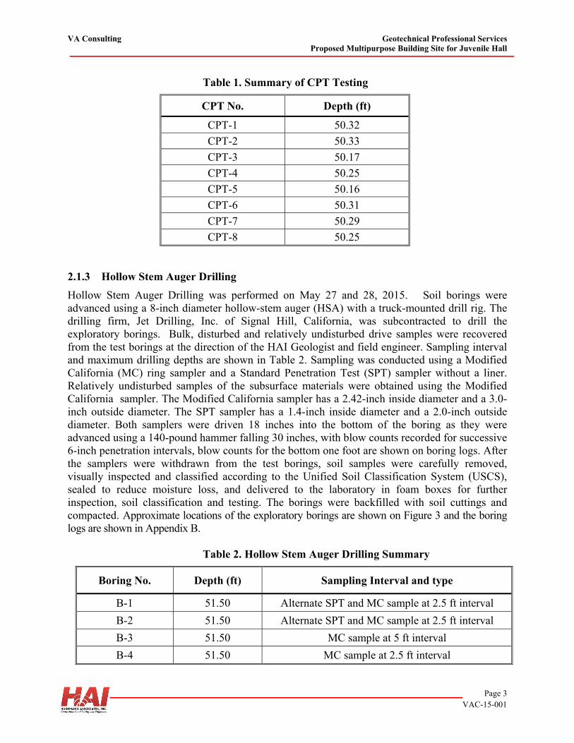
Table 1. Summary of CPT Testing
CPT No. Depth (ft)
CPT-1 50.32
CPT-2 50.33
CPT-3 50.17
CPT-4 50.25
CPT-5 50.16
CPT-6 50.31
CPT-7 50.29
CPT-8 50.25 2.1.3 Hollow Stem Auger Drilling
Hollow Stem Auger Drilling was performed on May 27 and 28, 2015. Soil borings were advanced using a 8-inch diameter hollow-stem auger (HSA) with a truck-mounted drill rig. The drilling firm, Jet Drilling, Inc. of Signal Hill, California, was subcontracted to drill the exploratory borings. Bulk, disturbed and relatively undisturbed drive samples were recovered from the test borings at the direction of the HAI Geologist and field engineer. Sampling interval and maximum drilling depths are shown in Table 2. Sampling was conducted using a Modified California (MC) ring sampler and a Standard Penetration Test (SPT) sampler without a liner. Relatively undisturbed samples of the subsurface materials were obtained using the Modified California sampler. The Modified California sampler has a 2.42-inch inside diameter and a 3.0-inch outside diameter. The SPT sampler has a 1.4-inch inside diameter and a 2.0-inch outside diameter. Both samplers were driven 18 inches into the bottom of the boring as they were advanced using a 140-pound hammer falling 30 inches, with blow counts recorded for successive 6-inch penetration intervals, blow counts for the bottom one foot are shown on boring logs. After the samplers were withdrawn from the test borings, soil samples were carefully removed, visually inspected and classified according to the Unified Soil Classification System (USCS), sealed to reduce moisture loss, and delivered to the laboratory in foam boxes for further inspection, soil classification and testing. The borings were backfilled with soil cuttings and compacted. Approximate locations of the exploratory borings are shown on Figure 3 and the boring logs are shown in Appendix B.
Table 2. Hollow Stem Auger Drilling Summary
Boring No. Depth (ft) Sampling Interval and type
B-1 51.50 Alternate SPT and MC sample at 2.5 ft interval
B-2 51.50 Alternate SPT and MC sample at 2.5 ft interval
B-3 51.50 MC sample at 5 ft interval
B-4 51.50 MC sample at 2.5 ft interval
VA Consulting Geotechnical Professional Services Proposed Multipurpose Building Site for Juvenile Hall
Page 4 VAC-15-001
2.2 LABORATORY TESTING
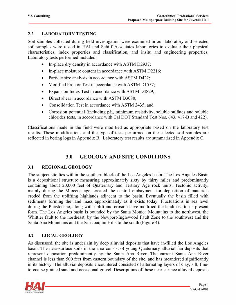
Soil samples collected during field investigation were examined in our laboratory and selected soil samples were tested in HAI and Schiff Associates laboratories to evaluate their physical characteristics, index properties and classification, and insitu and engineering properties. Laboratory tests performed included:
In-place dry density in accordance with ASTM D2937;
In-place moisture content in accordance with ASTM D2216;
Particle size analysis in accordance with ASTM D422;
Modified Proctor Test in accordance with ASTM D1557;
Expansion Index Test in accordance with ASTM D4829;
Direct shear in accordance with ASTM D3080;
Consolidation Test in accordance with ASTM 2435; and
Corrosion potential (including pH, minimum resistivity, soluble sulfates and soluble chlorides tests, in accordance with Cal DOT Standard Test Nos. 643, 417-B and 422).
Classifications made in the field were modified as appropriate based on the laboratory test results. These modifications and the type of tests performed on the selected soil samples are reflected in boring logs in Appendix B. Laboratory test results are summarized in Appendix C.
3.0 GEOLOGY AND SITE CONDITIONS
3.1 REGIONAL GEOLOGY
The subject site lies within the southern block of the Los Angeles basin. The Los Angeles Basin is a depositional structure measuring approximately sixty by thirty miles and predominantly containing about 20,000 feet of Quaternary and Tertiary Age rock units. Tectonic activity, mainly during the Miocene age, created the central embayment for deposition of materials eroded from the uplifting highlands adjacent to the basin. Eventually the basin filled with sediments forming the land mass approximately as it exists today. Fluctuations in sea level during the Pleistocene, along with uplift and erosion have modified the landmass to its present form. The Los Angeles basin is bounded by the Santa Monica Mountains to the northwest, the Whittier fault to the northeast, by the Newport-Inglewood Fault Zone to the southwest and the Santa Ana Mountains and the San Joaquin Hills to the south (Figure 4).
3.2 LOCAL GEOLOGY
As discussed, the site is underlain by deep alluvial deposits that have in-filled the Los Angeles basin. The near-surface soils in the area consist of young Quaternary alluvial fan deposits that represent deposition predominantly by the Santa Ana River. The current Santa Ana River channel is less than 500 feet from eastern boundary of the site, and has meandered significantly in its history. The alluvial deposits encountered consisted of alternating layers of clay, silt, fine-to-coarse grained sand and occasional gravel. Descriptions of these near surface alluvial deposits
VA Consulting Geotechnical Professional Services Proposed Multipurpose Building Site for Juvenile Hall
Page 5 VAC-15-001
are presented on the boring logs (Appendix B) and in the following section. Based on the borings excavated, layering is inconsistent. Direct correlations of the various deposits were difficult to conduct between borings and/or across either site. This is consistent with the migrating or wandering depositional environment related to the Santa Ana River. Minor artificial fills were encountered in the borings that were likely related to construction of the current facility. These deposits consisted of sand to sandy silt and were generally less than a few feet thick.
3.3 SUBSURFACE CONDITIONS
The subsurface conditions encountered in our borings and CPTs at the site generally consist of a few feet of artificial fill underlain by young alluvium. A discussion of the subsurface materials encountered is presented in the following sections and is separated by the preferred site and the alternate site. Detailed descriptions of the deposits are provided in our logs of borings and CPTs presented in Appendices A and B. The sampling indicated significant changes in material types over a few feet. It is likely that most of the individual layers are only a few inches to a few feet in thickness and laterally discontinuous over a few tens of feet. The thicker zones may be continuous over greater distances. In addition due to the depositional environment typically clay deposits are more continuous than sand rich deposits. For the preferred site borings B-1 and B-2, and CPT’s 1 through 4 were excavated to determine the subsurface conditions. The alluvial deposits encountered consisted of gravelly sands to fat clays. The majority of the deposits however, were silty to lean clays, with lesser silty sands and clayey sands. As discussed above the layering should be considered highly variable and inconsistent laterally due to their depositional environment (meandering stream deposit). Clay rich deposits were the most common and encountered in all of the excavations at various depths. While these clay rich zones were often in each of the excavations, it is difficult to determine how laterally continuous they are. It is likely that a few of the clay rich zones are continuous throughout the Preferred Site Area. Specifically, it appears that there were relatively consistent clay rich deposits encountered in most/all of the borings at depths of approximately 8 to 12 feet, 18 to 22 feet, 26 to 30 feet, 34 to 37 feet, and below 45 feet in depth. In all of the excavations there were also Sand rich deposit encountered around 38 feet in depth. There was a lesser defined silty sand to sandy silt zone encountered in all the borings from approximately 22 to 26 feet in depth. A third sand rich zone was encountered in two of the excavations at depths ranging from 13 to 16 feet (CPT-1 and B-1), and to a much lesser extent in B-2. It should be emphasized that although these deposits appear to be continuous, actual conditions may be less continuous. For the alternate site, borings B-3, B-4, and CPT’s 5 through 8 were excavated and used to model subsurface conditions. The alternate site has more sand rich deposits beneath it than the preferred site. However, it is difficult to model the continuity of the sands, since they were not consistently encountered in all the borings. In general the upper deposits to a depth of approximately 26 feet consisted primarily of silty sand to sand. In addition, sand rich zones were often encountered at depths of 24 feet, 38 feet, and 44 to 46 feet in depth. Clay rich deposits were encountered in all/most of the excavations with slightly varying thicknesses at depths of approximately 17 to 18 feet, 26 to 28 feet, and 46 to 48 feet.
VA Consulting Geotechnical Professional Services Proposed Multipurpose Building Site for Juvenile Hall
Page 6 VAC-15-001
The only sand rich zone that was consistent across both the Preferred and Alternate sites was encountered at a depth of approximately 38 feet below the ground surface. Continuous clay rich zones were encountered across both sites at depths of approximately 18 feet, 28 feet and below a depth of approximately 45 feet. A graphical summary of exploratory borings and CPT field data (i.e. soil penetration resistance) and laboratory test data (i.e. soil classification and index properties) of selected soil specimens versus depth is provided in Figures 5a and 5b for preferred site and alternate site, respectively. The soil profile specifically includes side by side plots of the following data versus depth:
Soil penetration resistance (Standard Penetration Test (SPT) and equivalent SPT N-values calculated from Modified California blow counts and CPT);
In situ dry density and moisture content;
Degree of saturation; and
Fines content (percent of soil passing No. 200 sieve). The moisture contents range between 12 and 26 percent and dry densities vary from 87 to 105 pounds per cubic foot (pcf) in preferred site. In alternate site, moisture contents range between 3 and 20 percent and the measured dry densities vary from 93 to 114 pcf.
3.4 GROUNDWATER
Groundwater was not encountered in the soil borings and CPTs performed for this investigation. Figure 6 is a plot of groundwater depth information provided by the Orange County Water District that indicates that in 2012 the depth to groundwater was approximately 103 feet below the ground surface (approximate elevation 133 above mean sea level) in both preferred and alternate locations. Based on the report prepared by Department of Mines and Geology (CDMG, 1997) for Anaheim Quadrangle, the historic high groundwater level is at a depth of 25 feet and 35 feet bgs at preferred site and alternate site, respectively (Figure 7), which were considered for liquefaction analyses.
4.0 SEISMICITY AND SEISMIC HAZARDS EVALUATION
4.1 REGIONAL FAULTS
The project site is in seismically active southern California, which contains a complex network of active and potentially active faults. The site is not located within a currently designated Alquist-Priolo Special Study Zone (Hart and Bryant, 1999). Figure 8 presents regional fault map. The major active and potentially active faults that could produce significant ground shaking at the site are summarized in Table 3 and discussed below.
VA Consulting Geotechnical Professional Services Proposed Multipurpose Building Site for Juvenile Hall
Page 7 VAC-15-001
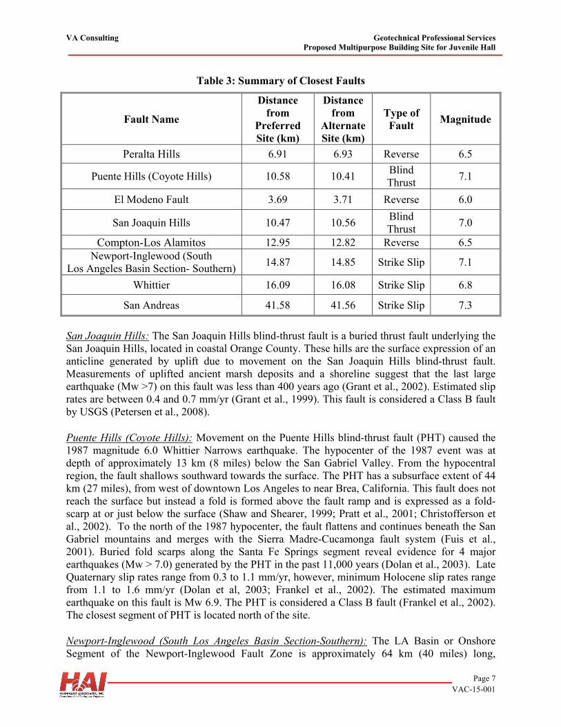
Table 3: Summary of Closest Faults
Fault Name
Distance from
Preferred Site (km)
Distance from
Alternate Site (km)
Type of Fault
Magnitude
Peralta Hills 6.91 6.93 Reverse 6.5
Puente Hills (Coyote Hills) 10.58 10.41 Blind Thrust
7.1
El Modeno Fault 3.69 3.71 Reverse 6.0
San Joaquin Hills 10.47 10.56 Blind Thrust
7.0
Compton-Los Alamitos 12.95 12.82 Reverse 6.5 Newport-Inglewood (South
Los Angeles Basin Section- Southern) 14.87 14.85 Strike Slip 7.1
Whittier 16.09 16.08 Strike Slip 6.8
San Andreas 41.58 41.56 Strike Slip 7.3
San Joaquin Hills: The San Joaquin Hills blind-thrust fault is a buried thrust fault underlying the San Joaquin Hills, located in coastal Orange County. These hills are the surface expression of an anticline generated by uplift due to movement on the San Joaquin Hills blind-thrust fault. Measurements of uplifted ancient marsh deposits and a shoreline suggest that the last large earthquake (Mw >7) on this fault was less than 400 years ago (Grant et al., 2002). Estimated slip rates are between 0.4 and 0.7 mm/yr (Grant et al., 1999). This fault is considered a Class B fault by USGS (Petersen et al., 2008). Puente Hills (Coyote Hills): Movement on the Puente Hills blind-thrust fault (PHT) caused the 1987 magnitude 6.0 Whittier Narrows earthquake. The hypocenter of the 1987 event was at depth of approximately 13 km (8 miles) below the San Gabriel Valley. From the hypocentral region, the fault shallows southward towards the surface. The PHT has a subsurface extent of 44 km (27 miles), from west of downtown Los Angeles to near Brea, California. This fault does not reach the surface but instead a fold is formed above the fault ramp and is expressed as a fold-scarp at or just below the surface (Shaw and Shearer, 1999; Pratt et al., 2001; Christofferson et al., 2002). To the north of the 1987 hypocenter, the fault flattens and continues beneath the San Gabriel mountains and merges with the Sierra Madre-Cucamonga fault system (Fuis et al., 2001). Buried fold scarps along the Santa Fe Springs segment reveal evidence for 4 major earthquakes (Mw > 7.0) generated by the PHT in the past 11,000 years (Dolan et al., 2003). Late Quaternary slip rates range from 0.3 to 1.1 mm/yr, however, minimum Holocene slip rates range from 1.1 to 1.6 mm/yr (Dolan et al, 2003; Frankel et al., 2002). The estimated maximum earthquake on this fault is Mw 6.9. The PHT is considered a Class B fault (Frankel et al., 2002). The closest segment of PHT is located north of the site. Newport-Inglewood (South Los Angeles Basin Section-Southern): The LA Basin or Onshore Segment of the Newport-Inglewood Fault Zone is approximately 64 km (40 miles) long,
VA Consulting Geotechnical Professional Services Proposed Multipurpose Building Site for Juvenile Hall
Page 8 VAC-15-001
extending southeastward from the Santa Monica fault to Newport Beach where it transitions to the Offshore Segment. The Onshore Segment is a discontinuous zone that is poorly exposed at the surface. The right-lateral, strike-slip fault zone is represented by a series of left-stepping en-echelon anticlines. This segment is located east of the project site. The estimated slip rate for this segment of the fault is 1.0±0.5 mm/yr (Freeman et al., 1992; WGCEP, 1995). The maximum moment magnitude earthquake along this segment of the fault has been estimated to be Mw 7.1 (Cao et al., 2003). This segment of the fault is considered a Type B fault by CDMG/USGS (Frankel et al., 2002; Petersen, et al., 2008). Peralta Hills: The Peralta Hills fault is an east-west trending, north-dipping reverse fault located on the south side of the Peralta Hills, 6.9 km (4.3 mile) from the project site. Mapping by Schoellhamer et al. (1981) and Morton et al. (1976) describe this fault as placing Miocene Puente Formation over Quaternary alluvial deposits (Wills, 1988). The fault has been investigated by various consultants; however, sufficient evidence for movement in the last 11,000 years has not yet been found (Wills, 1988). The Peralta Hills fault is not considered an active fault and is classified as potentially active by the California State Geological Survey (Wills, 1988). El Modeno Fault: The El Modeno fault is a northeast trending, southwest dipping normal fault mapped for 10 to 18 km (6.2 to 11 miles) from Peter’s Canyon Wash to Burrel Ridge. The El Modeno fault is poorly defined, as it is covered by Quaternary alluvium for much of its length. Significant evidence for Holocene activity has not yet been found for this fault which is generally considered as a potentially active fault at this time. It is unclear to what extent the Peralta Hills and the El Modeno faults interact near Burrul Ridge. Elsinore (Whittier Section): The Whittier fault is the northwestward extension of the Elsinore fault, a 250-km (155 miles) long fault that is traced from Los Angeles to northern Baja California in Mexico. The Whittier segment is approximately 40 km (25 miles) long, and extends from the Whittier Narrows section of the San Gabriel River southeastward to the Santa Ana River. Although no major historical earthquakes have been attributed to the Whittier fault, studies done by several investigators, most of which included trenching, have documented movement on this fault in the last 11,000 years (Hannan et at., 1979; Leighton 1987; Rockwell et al., 1988; Gath et al., 1992; Patterson and Rockwell, 1993). Slip rates on this fault range from 2.5 to 3 mm/yr (Rockwell et al., 1990; Gath et al., 1992). The estimated maximum earthquake to occur along the Whittier fault segment is Mw 7.0 (Petersen et al., 2008). The fault is classified as a Class A fault by the California Division of Mines and Geology (CDMG, Frankel et al., 2002) and United States Geological Survey (USGS, Petersen et al., 2008). The Whittier fault is located northeast of the site. San Andreas Fault: The San Andreas fault has been mapped from Cape Mendocino in northern California to an area near the Mexican border, a distance of over 1,000 km (about 625 miles). Its activity is known from historic earthquakes, most notable are the 1857 and 1906 magnitude 8 earthquakes, and from many fault studies, which have shown that the San Andreas offsets, or displaces, recently deposited sediments. The closest segments of the San Andreas fault to the project site are the San Bernardino and Southern segments, which ares located to the east-northeast of the project site. These segments are capable of producing an estimated maximum
VA Consulting Geotechnical Professional Services Proposed Multipurpose Building Site for Juvenile Hall
Page 9 VAC-15-001
moment magnitude (Mw) of 7.2 to 7.3 (Frankel et al., 2002; Petersen et al., 2008). Average slip rates along the San Bernardino and Southern segments are between 18 and 30 mm/yr (WGCEP, 1995; Salyards et al., 1992; Sieh, 1984). This fault is considered a Class A fault by the CDMG/USGS (Frankel et al., 2002; Petersen, et al., 2008).
4.2 SEISMIC HAZARDS AND DESIGN PARAMETERS CONSIDERATION
4.2.1 Fault Related Ground Rupture
The site is located within the seismically active area of southern California, but outside a Fault Hazard Zone defined by the Alquist-Priolo Earthquake Hazards Act (APEHA) of 1972 (Hart and Bryant, 1999). The proposed improvements should expect to experience at least one strong to severe seismic event during its anticipated lifetime. In general terms, an earthquake is caused when strain energy in rocks is suddenly released by movement along a plane of weakness. In some cases, fault movement propagates upward through the subsurface materials and causes displacement at the ground surface. Surface rupture usually occurs along traces of known or potentially active faults, although many historic events have occurred on faults not previously known to be active. Seismicity within this region is a result of the dominantly reverse-slip regime of the Transverse Ranges. Ground rupture caused by movement along a fault could likely result in catastrophic structural damage to buildings constructed along the fault trace. Consequently, the State of California via the APEHA prohibits the construction of occupied structures within the designated fault zones and requires demonstrating that the structure does not encroach upon a 50-foot setback from the fault trace. Local government agencies may identify additional faults, in addition to those faults mandated by the State, for which minimum construction setback requirements must be maintained. The proposed project site is not located inside a Fault Hazard Zone as delineated by the California Geological Survey. Fault related ground rupture is typically related to previous fault ground rupture from previous earthquakes. Therefore, the potential for ground rupture at the site related to an earthquake event is considered to be negligible. 4.2.2 Ground Shaking
The energy released during an earthquake propagates from its rupture surface in the form of seismic waves. The resulting strong ground motion from the seismic wave propagation can cause significant damage to structures. At any location, the intensity of the ground motion is a function of the distance to the fault rupture, the local soil/bedrock conditions, and the earthquake magnitude. Intensity is usually greater in areas underlain by unconsolidated material than in areas underlain by more competent rock. Earthquakes are characterized by a moment magnitude, which is a quantitative measure of the strength of the earthquake based on strain energy released during the event. The magnitude is independent of the site, but is dependent on several factors including the type of fault, rock type,
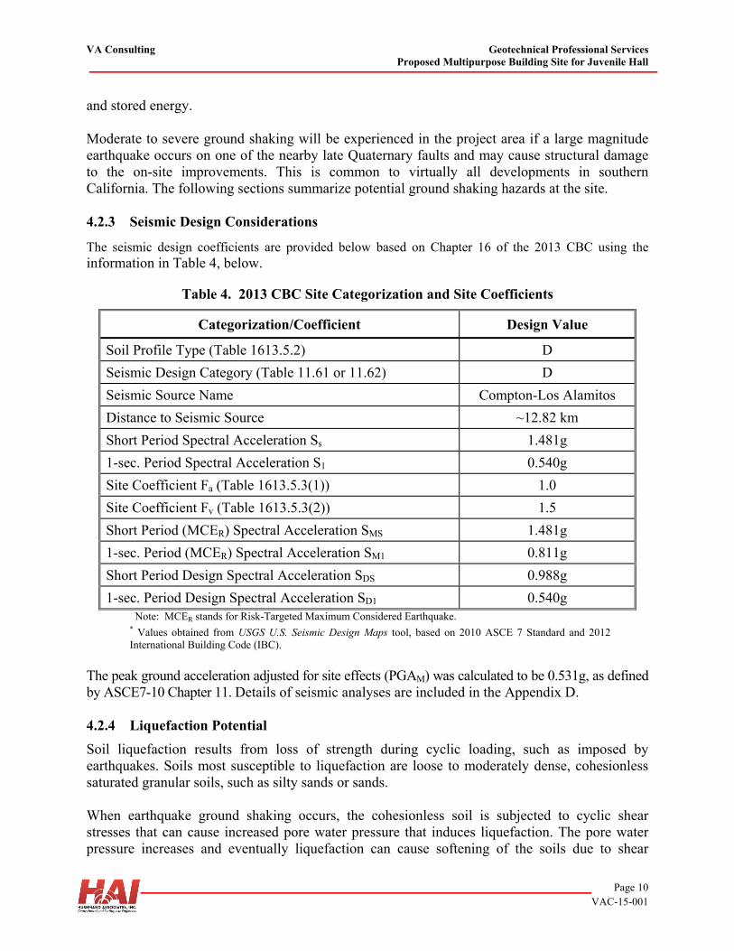
VA Consulting Geotechnical Professional Services Proposed Multipurpose Building Site for Juvenile Hall
Page 10 VAC-15-001
and stored energy. Moderate to severe ground shaking will be experienced in the project area if a large magnitude earthquake occurs on one of the nearby late Quaternary faults and may cause structural damage to the on-site improvements. This is common to virtually all developments in southern California. The following sections summarize potential ground shaking hazards at the site. 4.2.3 Seismic Design Considerations
The seismic design coefficients are provided below based on Chapter 16 of the 2013 CBC using the information in Table 4, below.
Table 4. 2013 CBC Site Categorization and Site Coefficients
Categorization/Coefficient Design Value
Soil Profile Type (Table 1613.5.2) D
Seismic Design Category (Table 11.61 or 11.62) D
Seismic Source Name Compton-Los Alamitos
Distance to Seismic Source ~12.82 km
Short Period Spectral Acceleration Ss 1.481g
1-sec. Period Spectral Acceleration S1 0.540g
Site Coefficient Fa (Table 1613.5.3(1)) 1.0
Site Coefficient Fv (Table 1613.5.3(2)) 1.5
Short Period (MCER) Spectral Acceleration SMS 1.481g
1-sec. Period (MCER) Spectral Acceleration SM1 0.811g
Short Period Design Spectral Acceleration SDS 0.988g
1-sec. Period Design Spectral Acceleration SD1 0.540g Note: MCER stands for Risk-Targeted Maximum Considered Earthquake.
* Values obtained from USGS U.S. Seismic Design Maps tool, based on 2010 ASCE 7 Standard and 2012 International Building Code (IBC).
The peak ground acceleration adjusted for site effects (PGAM) was calculated to be 0.531g, as defined by ASCE7-10 Chapter 11. Details of seismic analyses are included in the Appendix D. 4.2.4 Liquefaction Potential
Soil liquefaction results from loss of strength during cyclic loading, such as imposed by earthquakes. Soils most susceptible to liquefaction are loose to moderately dense, cohesionless saturated granular soils, such as silty sands or sands. When earthquake ground shaking occurs, the cohesionless soil is subjected to cyclic shear stresses that can cause increased pore water pressure that induces liquefaction. The pore water pressure increases and eventually liquefaction can cause softening of the soils due to shear
VA Consulting Geotechnical Professional Services Proposed Multipurpose Building Site for Juvenile Hall
Page 11 VAC-15-001
strength loss, and results in large cyclic deformations. Softening accompanied by a loss of shear strength may lead to large shear deformations or even flow failure under moderate to high shear stresses, such as beneath a foundation or sloping ground (NCEER/NSF, 1998). Loose granular soil can also settle (compact) during liquefaction as pore pressures dissipate following an earthquake. Very limited field data is available on this subject; however, in some cases, settlement on the order of 2 to 3 percent of the thickness of the liquefied zone has been measured. According to the State of California Geological Survey (CGS) Official Seismic Hazard Map for Anaheim quadrangle dated April 15, 1998, the proposed sites (both preferred and alternate) are located in a liquefaction-prone area (Figure 9). Groundwater was not encountered in the soil borings drilled to a maximum depth of approximately 51.5 feet. However, based on the report prepared by Department of Mines and Geology (CDMG, 1997) for Anaheim Quadrangle, the historic high groundwater level is at a depth of about 28 feet and 35 feet bgs, at preferred and alternate sites, respectively. Therefore, a detailed liquefaction study was performed as part of this investigation. CLiq software (ver 1.7.6.49) developed by GeoLogismik, was used for analyzing the CPT data using a method proposed by Boulanger and Idriss (2014). Details of liquefaction analyses are included in the Appendix E. 4.2.5 Earthquake Induced Lateral Spreading and Flow Failure
Lateral spreading typically occurs as a form of lateral displacement along liquefiable soils toward a free face such as river bank or slope face. As cracks develop within the weakened material, blocks of soil displace laterally. Cracking and lateral movement may gradually propagate away from the face as blocks continue to break free. Generally, failure in this mode is analytically unpredictable. However, due to the flat nature of site terrain, the potential for lateral spreading at the site is considered to be lower at the alternate site, as compared with the preferred site which is adjacent to a free face (Santa Ana River). For a site adjacent to a free face, lateral displacement may be ignored when liquefiable soils are present below a depth of two times height of free face (Idriss and Boulanger, 2008). At the preferred site, liquefiable layers are below the two times height of the slope of the channel (height of the slope is around 10 feet). Accordingly, the lateral spreading may be ignored. 4.2.6 Earthquake-Induced Settlement
Granular soils tend to densify when subjected to shear strains induced by ground shaking during earthquakes. Method proposed by Boulanger and Idriss (2014) was used to calculate the earthquake-induced settlement using CPT data in CLiq software. Settlement of loose and medium-dense sands could result from a strong earthquake for layers above the groundwater table. A detailed liquefaction study was performed as part of this investigation. Using the CPT data and the historically high groundwater table, the site soils were found to be potentially liquefiable below 30 feet and 38 feet bgs at preferred and alternate site, respectively. More accurate estimation of seismic settlement can be performed utilizing the CPT data, which provides a
VA Consulting Geotechnical Professional Services Proposed Multipurpose Building Site for Juvenile Hall
Page 12 VAC-15-001
continuous profile of subsurface soils, as compared with SPT data, which are obtained at the point of sampling. Eight (8) cone penetration tests (CPTs), CPT-1 through CPT-4 in preferred site and CPT-5 through CPT-8 in alternate site were performed to obtain more detailed and continuous subsurface conditions of the site. Based on the CPT data, the potential ground settlement due to soil liquefaction was calculated to be on the order of 1.3 to 2.0 inches at the preferred site and 0.5 to 1.2 inches at the alternate site. The liquefaction analyses and earthquake-induced settlements are presented in Appendix E. Based on the settlement calculation and considering the distance between the CPT locations, maximum differential settlement may be expected approximately 0.89 in per 100 ft and 0.25 in per 100 ft across the preferred and alternate sites, respectively. 4.2.7 Landslides
According to CGS (1998), the proposed site is not in a potential Earthquake-Induced Landslides zone. Due to the relatively low relief of the project site, the potential for landslide is considered to be low. 4.2.8 Ground Lurching
Lurching is the relative displacement of adjacent land surfaces during an earthquake. As the seismic motion encounters a cliff or bluff, a stream bank, or even a fill slope at the nearly right angles it may cause displacement of the material in the unsupported direction (Richter, 1958). Lurching may also be caused by liquefaction of a zone beneath the otherwise intact surface. Visible evidence of lurching includes ground cracking and fissuring generally in a relatively parallel fashion to a stream bank or slope face. Ground cracking caused by lurching is not related to the fault rupture. The potential for lurch cracking and lateral spreading is highest in areas where there is a high groundwater table, relatively soft and recent alluvium deposits, and where creek banks are relatively high. 4.2.9 Flooding Tsunamis and Seiches
Tsunamis, or seismic sea waves, are large oceanic waves generated by earthquakes, submarine volcanic eruptions or large submarine landslides. They are capable of traveling long distances across ocean basins, and can force large quantities of water up onto shore at high velocities. Seiches are waves with similar behavior, however, they are generally considered to be smaller, with low-energy waves that form in smaller bodies of water such as bays, rivers and lakes. The forces involved with tsunamis are of such large magnitude that the only positive means of protection is to avoid areas subject to tsunamis. The largest tsunami reported in California followed the 1812 earthquake, in which sea waves as high as 30 to 35 feet reached Santa Barbara. Due to the project’s location and elevation, flooding is not expected from intensive rainfall, tsunami or seiche, or dam or levee breaks.
VA Consulting Geotechnical Professional Services Proposed Multipurpose Building Site for Juvenile Hall
Page 13 VAC-15-001
5.0 FINDINGS AND CONCLUSIONS
5.1 GENERAL
The discussions and recommendations presented in the following sections are based on our understanding of the proposed project requirements, the results of our geotechnical investigation, and our professional judgment. Both preferred and alternate sites are not located in an Alquist-Priolo Earthquake Fault Zone but located in a liquefaction hazard zone. There are no known geologic hazards that would preclude the project as planned. It is our opinion that based on the above-cited geotechnical findings, both sites are suitable for the proposed improvements. Specific recommendations are provided for the preferred site in this report. Design and construction of the proposed project, should be performed based on the following recommendations.
5.2 EFFECT OF PROPOSED CONSTRUCTION ON ADJACENT PROPERTIES
It is our professional opinion that the proposed development will not adversely affect, nor be adversely affected by adjoining properties, with due precautions taken, and if our recommendations are implemented.
5.3 PRIMARY GEOTECHNICAL CONCERNS
Primary geotechnical concerns are the presence of unsuitable near surface soils and seismic settlement that may be mitigated based on the recommendations provided in this report.
5.4 SOIL EXPANSION POTENTIAL
According to the 2013 California Building Code (2013 CBC), soils meeting the following four requirements are considered expansive. The first three items shall not be required if the test prescribed in the last item is conducted:
Plasticity index (PI) greater than 15 (ASTM D4318), More than 10 percent of the soil particles pass a No. 200 sieve (ASTM D422), More than 10 percent of the soil particles are less than 5 micrometers in size (ASTM
D422), and Expansion index greater than 20, determined in accordance with ASTM D4829.
Expansion Index (EI) test conducted on the near-surface (0 to 5 feet) material for the preferred site at Boring B-2 yielded an EI of 17 as shown in Appendix C. Based on the result of our test, the shallow soils at Boring B-2 are considered non-expansive.
VA Consulting Geotechnical Professional Services Proposed Multipurpose Building Site for Juvenile Hall
Page 14 VAC-15-001
6.0 RECOMMENDATIONS
6.1 EARTHWORK
6.1.1 Clearing and Site Preparation
Prior to construction, the site should be cleared of all above-ground obstacles and structures. Existing utility and irrigation lines should be protected in-place, rerouted, or removed if they interfere with the proposed construction. The resulting cavities from removal of utility lines should be properly backfilled and compacted under the supervision of the project geotechnical engineer. Vegetation, debris, and organic matter should not be incorporated into the structural fill. 6.1.2 Over-excavation and Foundation Preparation
As stated before, near surface soils are not considered suitable for the support of the proposed development. Accordingly; existing onsite soils should be removed to a depth of 6.5 feet below existing ground surface or 4.5 feet below the bottom of the footings (whichever is deeper) and replaced as compacted fills. Actual depth of removal should be evaluated during observation and testing of grading by the geotechnical consultant. Lateral extent of remedial remval should be based on the recommendations provided subsequently for placement of geogrids reinforced subgrade used to partially mitigate liquefaction effects (see section 6.3). All fill should be placed and compacted in accordance with the recommendations for fill presented in the “Compaction” subsection. 6.1.3 Abandoned Utilities
Abandon utilities (if any) excavated during the remedial grading should be removed entirely and the end segments beyond the excavation zone should be plugged by concrete. 6.1.4 Subgrade Preparation
After the site has been properly cleared, stripped, and required overexcavations have been made, removal bottom areas receiving fill should be scarified in-place to a depth of 8 inches, moisture conditioned, and compacted in accordance with the recommendations for fill presented in the “Compaction” subsection. The finished compacted subgrade should be firm and non-yielding under the weight of compaction equipment. 6.1.5 Materials for Engineered Fill
The onsite soil, free of organic material, debris and oversize materials (greater than six inches in largest dimension) is suitable to be used in general fills. If import soil is considered as an alternative, the import soil should not exhibit an Expansion Index (EI) greater than 40 and contain more than 35 percent fines. The proposed import source should be screened by the geotechnical engineer for the following tests:
Gradation (ASTM D 422) Atterberg Limits (ASTM D 4318) Expansion Index (ASTM D 4829)
VA Consulting Geotechnical Professional Services Proposed Multipurpose Building Site for Juvenile Hall
Page 15 VAC-15-001
Soluble Sulfate, Soluble Chloride, and pH and Soil Resistivity (CT 417, CT 422, and CT 643) Additional tests may be required if the proposed import source passes the initial screening. 6.1.6 Fill Placement and Compaction
All fill, as well as scarified surface soils in those areas to receive fill, slabs-on-grade, or concrete flat works, should be compacted to at least 90 percent relative compaction as determined by ASTM Test Designation D1557, latest edition. Fill should be placed in lifts no greater than 8 inches in uncompacted thickness at moisture content near the laboratory optimum. Each successive lift should be firm and non-yielding under the weight of construction equipment. As stated subsequently, in order to minimize the differential settlement, placement of three (3) layers of geogrids within the compacted subgrade fills is recommended. 6.1.7 Temporary Excavation
All temporary excavations, including utility trenches, retaining wall excavations, and other excavations should be performed in accordance with project plans, specifications and all Occupational Safety and Health Administration (OSHA) requirements. The onsite soils generally conform to OSHA soil Type B. OSHA regulations are applicable in areas with no restriction of surrounding ground deformations. The soil type should be verified or revised based on geotechnical observation and testing during construction, as soil classifications may vary over short horizontal distances. In general, temporary excavation slopes should be no steeper than 1:1 (horizontal to vertical, [H: V]). These temporary excavation slopes recommendations are applicable to excavations less than 10 feet during normal construction periods, provided the slopes are maintained. If such slopes are constructed, we recommend that surface drainage be directed away from the top of the excavation, and that no construction equipment is operated and/or parked, or material is stockpiled within 10 feet from the top of the slope. It should be the Contractor’s responsibility to monitor the slopes and provide adequate and safe support for the excavation, as well as nearby structures. 6.1.8 Wet Weather Conditions
Earthwork contractors should be made aware of the moisture sensitivity of fine grain soils and potential compaction difficulties if encountered. If construction is undertaken during wet weather conditions, some of the surficial soils may become saturated, soft and unworkable.
6.2 POST-GRADING CONSIDERATIONS
6.2.1 Surface Drainage
Positive surface water drainage gradients (2% minimum) should be provided adjacent to the structures to direct surface water away from foundations and slabs towards suitable discharge facilities. Ponding of surface water should not be allowed on or adjacent to structures or pavements.
VA Consulting Geotechnical Professional Services Proposed Multipurpose Building Site for Juvenile Hall
Page 16 VAC-15-001
6.2.2 Utility Trench Backfill
The utility trench subgrade should be firm and unyielding and should be observed and tested by the geotechnical consultant prior to placing pipe bedding materials. The bedding materials should be composed of free draining sand, gravel, or crushed rock. If sand is used, the sand should have a Sand Equivalent (SE) greater than 30. Pipe bedding should extend below the pipe to a depth in accordance with the pipe manufacturer's specifications. The pipe bedding materials should extend to at least 12 inches over the top of pipe. Trench excavation above the pipe bedding may be backfilled with suitable onsite soils under the observation and testing of the geotechnical consultant. All fill soils should be placed in loose lifts, moisture-conditioned to two to three percent above optimum moisture content, and compacted to a minimum of 90 percent relative compaction as determined by ASTM Method D 1557. Lift thickness should follow the thickness specified in the latest edition of the Standard Specifications for Public Works Construction (SSPWC). The fill soils should extend to the bottom of the pavement structural section. Base material should be moisture-conditioned to between optimum and two percent above optimum moisture and compacted to a minimum of 95 percent relative compaction as determined by ASTM Method D 1557.
6.3 FOUNDATIONS
To reduce the impact of liquefaction and to provide adequate support for the proposed facility, using a combination of ground improvement and a spread footing connected with reinforced concrete tie beams/continuous footings may be considered for the project. In order to minimize the seismic-induce differential settlements, the use of 3 layers of geogrid within the compacted fill below foundation is recommended. The geogrids create a stiffened subgrade that spans underneath the proposed structure and thus, reduces the differential static and seismic settlements. Recommendations for the spread/continuous foundations are provided assuming ground improvement with geogrid layers in combination with spread footings connected with tie beam/continuous footings are considered to reduce the adverse impact of liquefaction-induced settlements. 6.3.1 Geogrid Reinforced Fills
The use of geogrids has proven to cost-effectively improve the bearing capacity and settlement performance of structures. Geogrids are one of the commonly used forms of reinforcement, which are polymeric grids formed by a regular network of integrally connected multi-directional tensile elements of appropriate orientation, size and shape with apertures of appropriate size and shape to allow interlocking with surrounding soil, rock, or earth to function primarily as reinforcement. For a geogrid reinforced subgrade, more than one layer of geogrid reinforcement is placed within layers of engineered fill material to create a composite material with improved performance characteristics. Some possible advantages of using the geogrids as reinforcement are as follows:
VA Consulting Geotechnical Professional Services Proposed Multipurpose Building Site for Juvenile Hall
Page 17 VAC-15-001
Spreading differential displacements and also reducing angular distortions relative to a distinct offset in an underlying normal or reverse bedrock fault (Bray et al., 1993 and Bray, 2001).
Reduce total and differential settlements by forming a stiffened mat beneath concrete footings.
Improve the margin of safety against unforeseen soil conditions. Increase the effective bearing capacity of the soils, thus reduce size of the footing.
Based on the information provided by the specialty subconsultant (Tensar Corporation, LLC) presented in Appendix F, the following steps may be implemented for placement of geogrids (see figure in Appendix F):
Excavation and Compaction: Remedial removals depth should be performed based on the recommendations provided before. Lateral extent of remedial removals should be extended horizontally a minimum of 10 feet beyond the footprint of improvements.
Placement of Geogrid: Place the first layer of Geogrid TriAx TX7 or similar alternate geogrid materials (specifications provided in Appendix F) in position over the prepared removal bottom and anchor it according to the manufacturer's recommendations. The other two geogrid layers shall be placed in 2.0 feet intervals. Geogrid may be temporarily secured in place with staples, pins, sand bags or backfill as required by fill properties, fill placement procedures or weather conditions.
Overlaps: Overlap the geogrid a minimum of one foot or as recommended by the manufacturer. Care shall be taken to ensure that structural geogrid sections do not separate at overlaps during construction. To prevent separation, simple joining methods may be utilized, such as wire ties, plastic ties, hog rings, staples or hooks. Maximum joint spacing of 20 to 30 feet is normally adequate to prevent grid separation at overlaps.
Placement of Engineering Fill: Place the layer(s) of engineered fill per Section 6.1.5, “Material for Fill”, specification and compact the soils using appropriate compaction equipment per Section 6.1.6, “Compaction”, to the specified relative density in position over the previous prepared layer of geogid/compacted fill.
Placement of Layers of Geogrid and Fill: Place the layers of geogrid and fill materials as explained above. The structural geogrid shall be oriented such that the roll direction runs perpendicular to the roll direction of the previous layer of geogrid. After placement of the third geogrid layer, place additional layers of engineered fill to reach the design elevation. A minimum of 6 inches of compacted engineering fill is required to cover the last layer of geogrid before placing the footing on the geogrid reinforced subgrade.
Placement of the Footing: Place the footing on the geogrid reinforced subgrade per recommendations in the next section.
Fill material shall be placed, spread and compacted in such a manner that minimizes the development of wrinkles in the geogrid and/or movement of the geogrid. A minimum loose fill thickness of 6 inches is required prior to operation of tracked vehicles over the geogrid. Turning of tracked vehicles should be kept to a minimum to prevent tracks from displacing the fill and damaging the geogrid. Sudden braking and sharp turning movements shall be avoided.
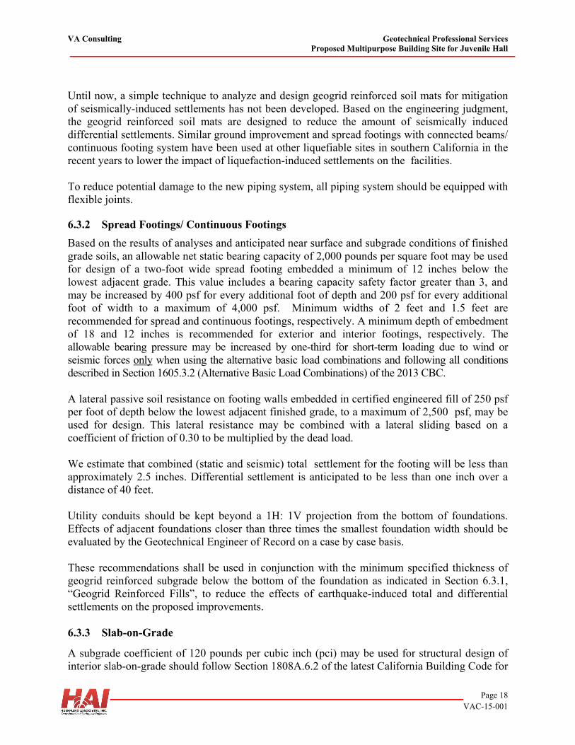
VA Consulting Geotechnical Professional Services Proposed Multipurpose Building Site for Juvenile Hall
Page 18 VAC-15-001
Until now, a simple technique to analyze and design geogrid reinforced soil mats for mitigation of seismically-induced settlements has not been developed. Based on the engineering judgment, the geogrid reinforced soil mats are designed to reduce the amount of seismically induced differential settlements. Similar ground improvement and spread footings with connected beams/ continuous footing system have been used at other liquefiable sites in southern California in the recent years to lower the impact of liquefaction-induced settlements on the facilities. To reduce potential damage to the new piping system, all piping system should be equipped with flexible joints. 6.3.2 Spread Footings/ Continuous Footings
Based on the results of analyses and anticipated near surface and subgrade conditions of finished grade soils, an allowable net static bearing capacity of 2,000 pounds per square foot may be used for design of a two-foot wide spread footing embedded a minimum of 12 inches below the lowest adjacent grade. This value includes a bearing capacity safety factor greater than 3, and may be increased by 400 psf for every additional foot of depth and 200 psf for every additional foot of width to a maximum of 4,000 psf. Minimum widths of 2 feet and 1.5 feet are recommended for spread and continuous footings, respectively. A minimum depth of embedment of 18 and 12 inches is recommended for exterior and interior footings, respectively. The allowable bearing pressure may be increased by one-third for short-term loading due to wind or seismic forces only when using the alternative basic load combinations and following all conditions described in Section 1605.3.2 (Alternative Basic Load Combinations) of the 2013 CBC. A lateral passive soil resistance on footing walls embedded in certified engineered fill of 250 psf per foot of depth below the lowest adjacent finished grade, to a maximum of 2,500 psf, may be used for design. This lateral resistance may be combined with a lateral sliding based on a coefficient of friction of 0.30 to be multiplied by the dead load. We estimate that combined (static and seismic) total settlement for the footing will be less than approximately 2.5 inches. Differential settlement is anticipated to be less than one inch over a distance of 40 feet. Utility conduits should be kept beyond a 1H: 1V projection from the bottom of foundations. Effects of adjacent foundations closer than three times the smallest foundation width should be evaluated by the Geotechnical Engineer of Record on a case by case basis. These recommendations shall be used in conjunction with the minimum specified thickness of geogrid reinforced subgrade below the bottom of the foundation as indicated in Section 6.3.1, “Geogrid Reinforced Fills”, to reduce the effects of earthquake-induced total and differential settlements on the proposed improvements. 6.3.3 Slab-on-Grade
A subgrade coefficient of 120 pounds per cubic inch (pci) may be used for structural design of interior slab-on-grade should follow Section 1808A.6.2 of the latest California Building Code for
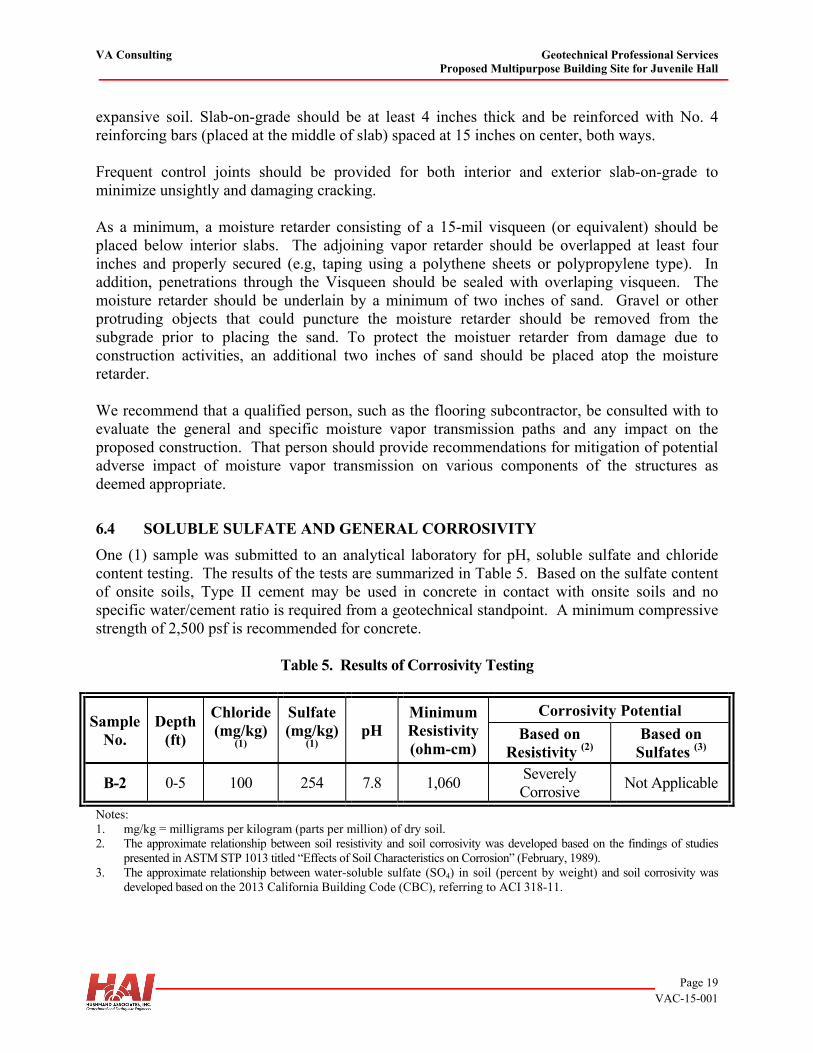
VA Consulting Geotechnical Professional Services Proposed Multipurpose Building Site for Juvenile Hall
Page 19 VAC-15-001
expansive soil. Slab-on-grade should be at least 4 inches thick and be reinforced with No. 4 reinforcing bars (placed at the middle of slab) spaced at 15 inches on center, both ways. Frequent control joints should be provided for both interior and exterior slab-on-grade to minimize unsightly and damaging cracking. As a minimum, a moisture retarder consisting of a 15-mil visqueen (or equivalent) should be placed below interior slabs. The adjoining vapor retarder should be overlapped at least four inches and properly secured (e.g, taping using a polythene sheets or polypropylene type). In addition, penetrations through the Visqueen should be sealed with overlaping visqueen. The moisture retarder should be underlain by a minimum of two inches of sand. Gravel or other protruding objects that could puncture the moisture retarder should be removed from the subgrade prior to placing the sand. To protect the moistuer retarder from damage due to construction activities, an additional two inches of sand should be placed atop the moisture retarder. We recommend that a qualified person, such as the flooring subcontractor, be consulted with to evaluate the general and specific moisture vapor transmission paths and any impact on the proposed construction. That person should provide recommendations for mitigation of potential adverse impact of moisture vapor transmission on various components of the structures as deemed appropriate.
6.4 SOLUBLE SULFATE AND GENERAL CORROSIVITY
One (1) sample was submitted to an analytical laboratory for pH, soluble sulfate and chloride content testing. The results of the tests are summarized in Table 5. Based on the sulfate content of onsite soils, Type II cement may be used in concrete in contact with onsite soils and no specific water/cement ratio is required from a geotechnical standpoint. A minimum compressive strength of 2,500 psf is recommended for concrete.
Table 5. Results of Corrosivity Testing
Sample No.
Depth (ft)
Chloride (mg/kg)
(1)
Sulfate (mg/kg)
(1) pH
Minimum Resistivity (ohm-cm)
Corrosivity Potential
Based on Resistivity (2)
Based on Sulfates (3)
B-2 0-5 100 254 7.8 1,060 Severely Corrosive
Not Applicable
Notes: 1. mg/kg = milligrams per kilogram (parts per million) of dry soil. 2. The approximate relationship between soil resistivity and soil corrosivity was developed based on the findings of studies
presented in ASTM STP 1013 titled “Effects of Soil Characteristics on Corrosion” (February, 1989). 3. The approximate relationship between water-soluble sulfate (SO4) in soil (percent by weight) and soil corrosivity was
developed based on the 2013 California Building Code (CBC), referring to ACI 318-11.
VA Consulting Geotechnical Professional Services Proposed Multipurpose Building Site for Juvenile Hall
Page 20 VAC-15-001
The above tests were performed for screening purposes only. Our firm does not practice corrosion engineering; therefore, we recommend that a corrosion engineer be retained to evaluate the corrosion potential of the onsite soils and any impact on the proposed project sewer line and structures.
6.5 DISPOSAL OF CONTAMINATED SOIL
If contaminated soils are encountered during excavation, they should be disposed properly. Disposal of any contaminated soil or water should be in accordance with the local and county guidelines and jurisdictions.
7.0 ADDITIONAL SERVICES
7.1 REVIEW OF CONSTRUCTION PLANS AND SPECIFICATIONS
Subsurface conditions may vary from those predicted by relatively small diameter and widely spaced exploration borings performed during this investigation. Should conditions that are different from those described herein be observed during construction, supplemental investigation would be warranted. In addition, we recommend that the grading and foundation plans and specifications be reviewed by the geotechnical consultant. Technical specifications should include provisions for conformance testing consistent with the recommendations made in this report.
7.2 GEOTECHNICAL OBSERVATION AND TESTING
We recommend that observation and testing be performed by the geotechnical consultant during the following stages of construction:
Grading operations, including excavations and placement of compacted fill and geogrids, Foundation excavations and installation, Removal or installation of support of buried utilities or structures, and When any unusual subsurface conditions are encountered.
8.0 LIMITATIONS
This report has been prepared for the sole use of VA Consulting, specifically for design of the Multi-Purpose Building Facility in Orange, California. The opinions presented in this report have been formulated in accordance with existing accepted geotechnical engineering practices in the southern California at the time this report was written. No other warranty, express or implied, is made or should be inferred. The opinions, conclusions and recommendations contained in this report are based upon the information obtained from our investigation, which includes data from widely separated discrete sampling locations, visual observations from our site reconnaissance, and review of other geotechnical data provided to us, along with local experience and engineering judgment. The recommendations presented in this report are based on the assumption that soil and geologic conditions at or between borings do not deviate substantially from those encountered or
VA Consulting Geotechnical Professional Services Proposed Multipurpose Building Site for Juvenile Hall
Page 21 VAC-15-001
extrapolated from the information collected during our investigation. We are not responsible for the data presented by others. We should be retained to review the geotechnical aspects of the final plans and specifications for conformance with our recommendations. The recommendations provided in this report are based on the assumption that HAI will be retained to provide observation and testing services during construction to confirm that conditions are similar to that assumed for design and to form an opinion as to whether the work has been performed in accordance with the project plans and specifications. If we are not retained for these services, HAI cannot assume any responsibility for any potential claims that may arise during or after construction as a result of misuse or misinterpretation of HAI’s report by others. Furthermore, HAI will cease to be the Geotechnical-Engineer-of-Record if we are not retained for these services and/or at the time another consultant is retained for follow up service to this report. The opinions presented in this report are valid as of the present date for the property evaluated. Changes in the condition of the property will likely occur with the passage of time due to natural processes and/or the works of man. In addition, changes in applicable standards of practice can occur as a result of legislation and/or the broadening of knowledge. Furthermore, geotechnical issues may arise that were not apparent at the time of our investigation. Accordingly, the opinions presented in this report may be invalidated, wholly or partially, by changes outside of our control. Therefore, this report is subject to review and should not be relied upon after a period of three years, nor should it be used, or is it applicable, for any other property.
9.0 REFERENCES
ASTM Standards, 2014, Section Four: Construction. Volume 04.08, Soil and Rock (I): D 420 – D 5611.
ACI Standard and Commentary, 2011, Building Code Requirements for Structural Concrete
(ACI 318-11) and Commentary, American Concrete Institute, 2011 Bray, J.D., Ashmawy, A., Mukhopadhyay, G. and Gath, E.M. (1993). “Use of Geosynthetics to
Mitigate Earthquake Fault Rupture Propagation Through Compacted Fill”, Proceedings of the Geosynthetics ’93 Conference, Vol. 1,379-392.
Bray, J.D. (2001), Developing Mitigation Measures for Hazards Associated with Earthquake
Surface Fault Rupture, A Workshop on Seismic Fault- Induced Failures– Possible Remedies for Damage to Urban Facilities, Japan Society for the Promotion of Science, Japan, pp. 55-79, January 11-12, 2001.
California Building Code based on 2012 International Building Code, 2013 California Building Code.
VA Consulting Geotechnical Professional Services Proposed Multipurpose Building Site for Juvenile Hall
Page 22 VAC-15-001
California Division of Mines and Geology (CDMG, renamed California Geological Survey), 1997, Seismic Hazard Zone Report for the Anaheim and Newport Beach 7.5 Minute Quadrangle, Orange County, California.
California Geological Survey (CGS), 1998, Seismic Hazard Zones Map for Anaheim quadrangle. California Department of Transportation (Caltrans)’s ARS Online Tool, version 2.3.06 Cao, T., Bryant, W.A., Rowshandel, B., Branum, D., and Wills, C.J., 2003, The Revised 2002
California Probabilistic Seismic Hazard Maps, dated June 2003, 11p. Accessible at http://www.consrv.ca.gov/cgs/rghm/psha/index.htm
Cliq v 1.7.6.52, Geologismiki Christofferson, S.C., Dolan, J.F., Shaw, J.H., 2002, Blind-Thrust Faults Unveiled, Southern
California Earthquake Center Annual Meeting Program and Abstracts, Fall 2002. Dolan, J.F., Christofferson, S.C., Shaw, J.H., 2003, Recognition of Paleoearthquakes on the
Puente Hills Blind Thrust Fault, California, Science, Volume 300, No. 5616, pp. 15-118. Chake, V., Palmer, J.D.,1989, Effects of soil characteristics on corrosion, ASTM STP 1013 Frankel, A.D., Petersen, M.D., Mueller, C.S., Haller, K.M., Wheeler, R.L., Leyendecker, E.V.,
Wesson, R.L., Harmsen, S.C., Cramer, C.H., Perkins, D.M., and Rukstales, K.S., 2002, Documentation for the 2002 Update of the National Seismic Hazard Maps: U.S., Geological Survey, Open File Report 02-420, 33p.
Gath, E.M., Gonzalez, T., and Rockwell, T.K., 1992, Final Technical Report-Evaluation of the
Late Quaternary Rate of Slip, Whittier Fault, Southern California, U.S. Geological Survey, Contract No. 14-08-0001-G1696, pp.
Grant, L. B., Mueller, K. J., Gath, E. M., Cheng, H., Edwards, R. L., Munro, R., Kennedy, G. L.,
1999, Late Quaternary Uplift and Earthquake Potential of the San Joaquin Hills, Southern Los Angeles Basin, California, Geology, Vol. 27, No. 11, pp. 1031 to 1034.
Grant, Lisa B.; Ballenger, Leslie J.; Runnerstrom, Eric E. (2002), Coastal Uplift of the San
Joaquin Hills, Southern Los Angeles Basin, California, by a Large Earthquake since A.D. 1635, Bulletin of the Seismological Society of America 92 (2): pp. 590–599, April 2002
Hart, E.W. and Bryant, W.A., 1999, Fault-Rupture Hazard Zones in California, Alquist-Priolo
Earthquake Fault Zoning Act with Index to Earthquake Fault Zones Maps: California Division of Mines and Geology, Special Publication 42, 38 p.
Hannan, D.L., Lung, R., and Leighton, F.B., 1979, Geologic Investigation of Regency of Fault
Activity by Surface Trenching on the Whittier Fault, California, U.S. Geological Survey,
VA Consulting Geotechnical Professional Services Proposed Multipurpose Building Site for Juvenile Hall
Page 23 VAC-15-001
Final Technical Report, Contract No. 14-08-0001-16821 issued to Leighton and Associates.
Idriss, I.M, Boulanger, R.W., 2008, Soil Liquefaction during Earthquakes, Earthquake
Engineering Research Institute, Monograph MNO-12 Idriss, I.M, Boulanger, R.W., 2010, SPT-Based Liquefaction Triggering Procedures, Center for
Geotechnical Modeling, University of California, Davis, Report No. UCD/CGM-10-02, December 2010
Idriss, I.M, Boulanger, R.W., 2014, CPT And SPT based Liquefaction Triggering Procedures, Center for Geotechnical Modeling, University of California, Davis, Report No. UCD/CGM-14/01, April 2014 Ishihara, K. and Yoshimine, M., 1992, Evaluation of Settlements in Sand Deposits Following
Liquefaction During Earthquakes, Soils and Foundations, 32 (1): 173-188. Jennings, C. W., 1994, Fault Activity Map of California and Adjacent Areas, with Locations and
Ages of Recent Volcanic Eruptions: California Department of Conservation, Division of Mines and Geology, Geologic Data Map Series, Map No. 6 - Faults, Locations of Recent Volcanic Eruptions, Scale 1:750,000.
Levi, S., and Yeats, R.S., 1993, Paleomagnetic Constraints on the Initiation of Uplift on the
Santa Susana Fault, Western Transverse Ranges, California: Tectonics, Volume 12, No. 3, pp. 688-702.
Leighton and Associates, 1987, Fault Activity and Recurrence Intervals of the Western Segment of
the Whittier Fault, California: Unpublished Report to the U.S. Geological Survey, Contract No. 14-08-0001-21368, August 14, 1987.
Morton, P.K., Miller, R.V., Evans, J.R., 1976, Environmental Geology of Orange County, California, Open File Report 79-8 LA pp.88-96.
Petersen, M. D., Frankel, A. D., Harmsen, S. C., Mueller, C. S., Haller, K. M., Wheeler, R. L.,
Wesson, R. L., Zeng, Y., Boyd, O. S., Perkins, D. M., Luco, N., Field, E. H., Wills, C. J., and Rukstales, K. S., 2008, Documentation for the 2008 Update of the United States National Seismic Hazard Maps, Open-File Report 2008-1128.
Pradel, D., 1998, Procedure to Evaluate Earthquake-Induced Settlements in Dry Sandy Soils:
Journal of Geotechnical and Geoenvironmental Engineering, ASCE, Vol. 124, No. 4, pgs. 364-368.
Richter, C.F., 1958, Elementary Seismology, pp. 124-125. Robertson, P.K., 1990, Soil classification using the cone penetration test, Canadian Geotechnical
Journal, Volume 27 (1), pp. 151-158.
VA Consulting Geotechnical Professional Services Proposed Multipurpose Building Site for Juvenile Hall
Page 24 VAC-15-001
Robertson, P.K. and Wride, C.E., 1998, Cyclic Liquefaction and its Evaluation based on the CPT , Canadian Geotechnical Journal, 1998, Vol. 35, August. Rockwell, T.K., Gath, E.M., and Cook, K.D., 1988, Soil Chronology and Tectonic
Geomorphology of the Whittier Fault Zone, Yorba Linda, California: A Preliminary estimate of ate Quaternary Lateral Slip Rate: in Gath, E.M., Cann, L.R., (editors), Neotectonics of the Whittier Fault, Association of Engineering Geologists, Southern California Section Field Trip Guidebook, June 4, 1988.
Rockwell, T.K., Klinger, R., and Goodmacher, J., 1990, Determination of slip rates and dating
of earthquakes for the San Jacinto and Elsinore fault zones, in Kooser, M.A., and Reynolds, R.E., eds., Geology Around the Margins of the Eastern San Bernardino Mountains, Volume 1: Inland Geological Society, Redlands, p. 51-56
Salyards, S.L., Sieh, K.E., and Kirschvink, J.L., 1992, Paleomagnetic Measurement of Non-
brittle Cosesimic Deformation Across the San Andreas Fault at Pallet Creek, Journal of Geophysical Research, v.96, p.12,457-12,470.
Schoellhamer, J. E., Vedder, J. G., Yerkes, R. F., and Kinner, D. M., 1981, Geology of the
Northern Santa Ana Mountains, U. S. Geological Survey Professional Paper 420-D. Seih, K.E., 1984, Lateral Offset and Revised Dates of Large Prehistoric Earthquakes at Pallet
Creek, Southern California, Journal of Geophysical Research, v.89, p.764-17670. Shaw J.H., Plesch A., Pratt, T.L., Dolan, J.F., Fiore, P., 2002, Puente Hills Blind-Thrust System,
Los Angeles, California, American Association for the Advancement of Science, Volume 92, pp. 2946-2960.
Shaw J.H., Peter M. Shearer, 1999, An Elusive Blind-Thrust Fault Beneath Metropolitan Los
Angeles, California, Volume 283, no. 5407, pp. 1516-1518 Tokimatsu, K. and Seed, H. B., 1987, Evaluation of Settlements in Sands Due to Earthquake
Shaking: Journal of Geotechnical Engineering, ASCE, Vol. 113, No. 8, pgs. 861-878. Wills, C.J., 1988b, Peralta Hills fault: California Division of Mines and Geology Fault
Evaluation Report 194, 10 p., 6 figures, in Fault Evaluation Reports Prepared Under the Alquist-Priolo Earthquake Fault Zoning Act, Region 2 – Southern California: California Geological Survey CGS CD 2002-03 (2002).
Whitcomb, J.H., Allen, C.R., Garmany, J.D., and Hileman, J.A., 1973, San Fernando
Earthquakes Series, 1971 – Focal Mechanisms and Tectonics: Review of Geophysics, Volume11, p.693-730.
VA Consulting Geotechnical Professional Services Proposed Multipurpose Building Site for Juvenile Hall
Page 25 VAC-15-001
Working Group on California Earthquake Probabilities, 1995, Seismic Hazards in Southern California, 1994 to 2024: Bulletin of the Seismological Society of America, Volume 85, No. 2, pp. 379-439, pp. 379-439.
Youd, T.L., and Idriss, I.M., 1997, NCEER workshop on evaluation of liquefaction resistance of
soils, National Center for Earthquake Engineering Research Technical Report NCEER-97-0022, pp. 276 p.
Youd, T.L., Idriss, I.M., Andrus, R.D., Arango, I., Castro, G., Christian, J.T., Dobry, R., Finn,
W.D.L., Harder, L.F., Hynes, M.E.,Ishihara, K., Koester, J., Liao, S., Marcuson III, W.F., Martin, G.R., Mitchell, J.K., Moriwaki, Y., Power, M.S., Robertson, P.K.,Seed, R., and Stokoe, K.H., Liquefaction Resistance of Soils: Summary Report from the 1996 NCEER and 1998 NCEER/NSF Workshop on Evaluation of Liquefaction Resistance of Soils, ASCE, Journal of Geotechnical & Geoenvironmental Engineering, Vol. 127, October, pp 817-833

FIGURES
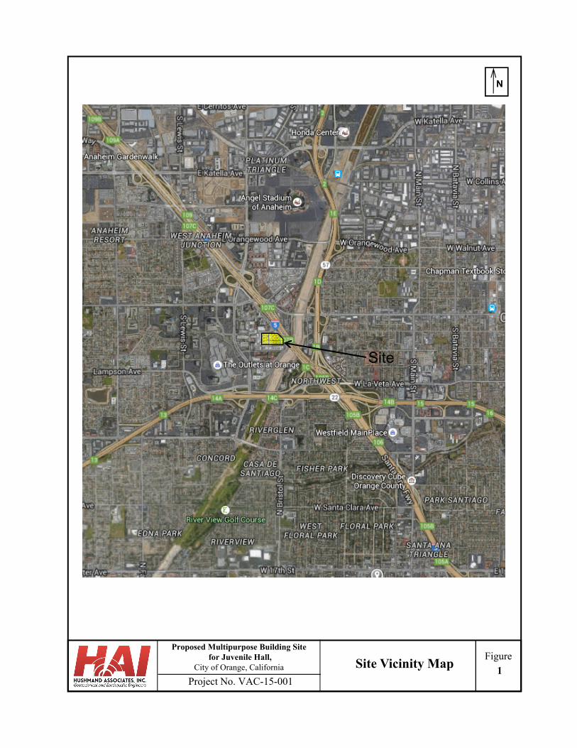
Project No. VAC-15-001
FigureProposed Multipurpose Building Site
for Juvenile Hall, City of Orange, California
N
Site Vicinity Map1
Site
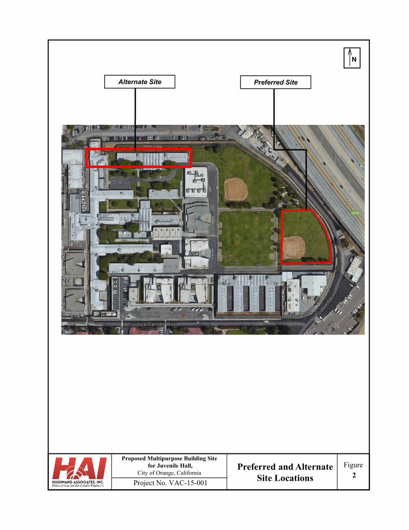
Project No. VAC-15-001
FigureProposed Multipurpose Building Site
for Juvenile Hall, City of Orange, California
N
Preferred SiteAlternate Site
Preferred and Alternate Site Locations 2
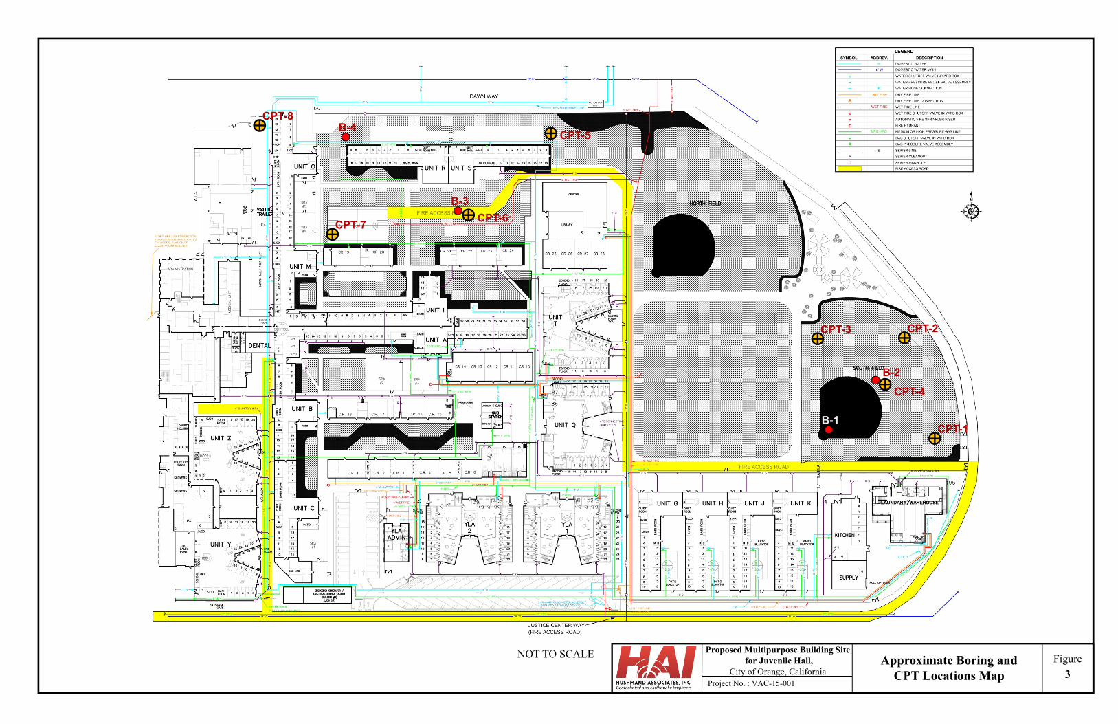
Figure
Project No. : VAC-15-001
Proposed Multipurpose Building Sitefor Juvenile Hall,
City of Orange, California
NOT TO SCALE
3
B-1
B-2
B-3
B-4
CPT-1
CPT-4
CPT-2CPT-3
CPT-5
CPT-6
CPT-8
CPT-7
Approximate Boring and CPT Locations Map
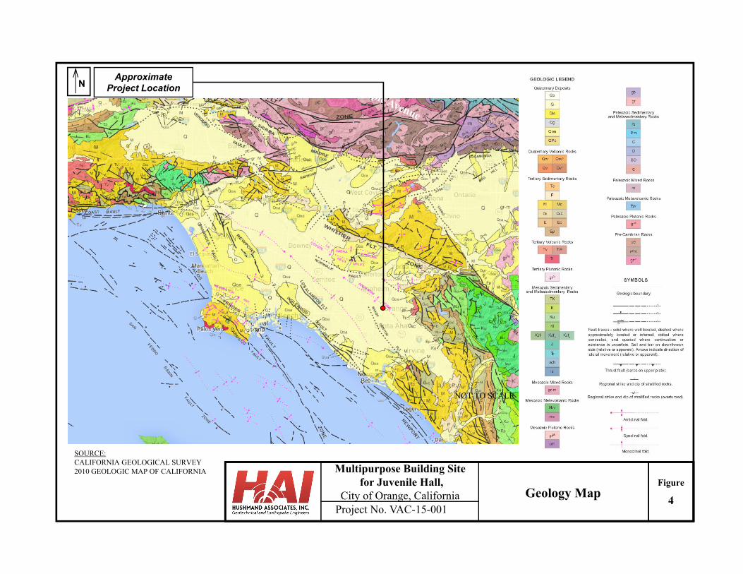
Project No. VAC-15-001
Multipurpose Building Sitefor Juvenile Hall,
City of Orange, CaliforniaFigure
Geology Map4
NApproximate
Project Location
NOT TO SCALE
SOURCE:CALIFORNIA GEOLOGICAL SURVEY2010 GEOLOGIC MAP OF CALIFORNIA
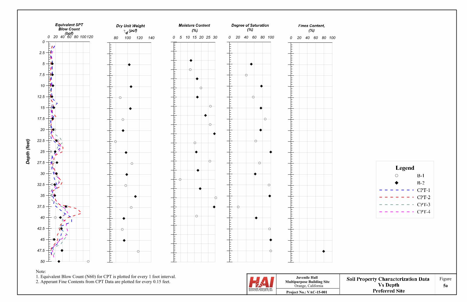
80 100 120 1400 20 40 60 80 100120
50
47.5
45
42.5
40
37.5
35
32.5
30
27.5
25
22.5
20
17.5
15
12.5
10
7.5
5
2.5
0
Dep
th (
feet
)
0 5 10 15 20 25 30 0 20 40 60 80 100 0 20 40 60 80 100
Note:1. Equivalent Blow Count (N60) for CPT is plotted for every 1 foot interval.2. Apperant Fine Contents from CPT Data are plotted for every 0.15 feet.
Figure
Project No.: VAC-15-001
Juvenile HallMultipurpose Building Site
Orange, California
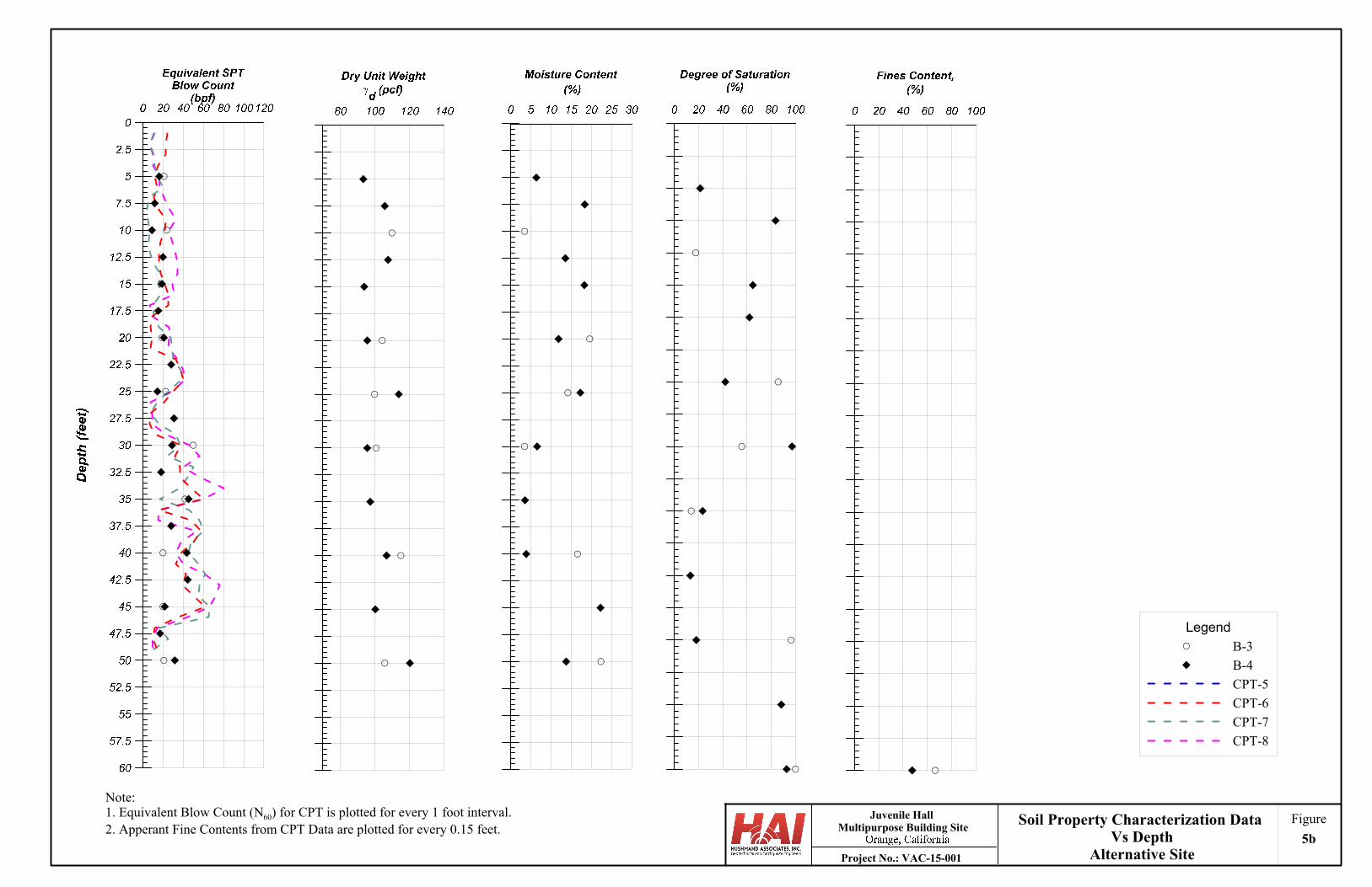
Legend
B-3
B-4
CPT-5
CPT-6
CPT-7
CPT-8
Note:1. Equivalent Blow Count (N60) for CPT is plotted for every 1 foot interval.2. Apperant Fine Contents from CPT Data are plotted for every 0.15 feet.
FigureSoil Property Characterization DataVs Depth
Alternative SiteProject No.: VAC-15-001
Juvenile HallMultipurpose Building Site
5b
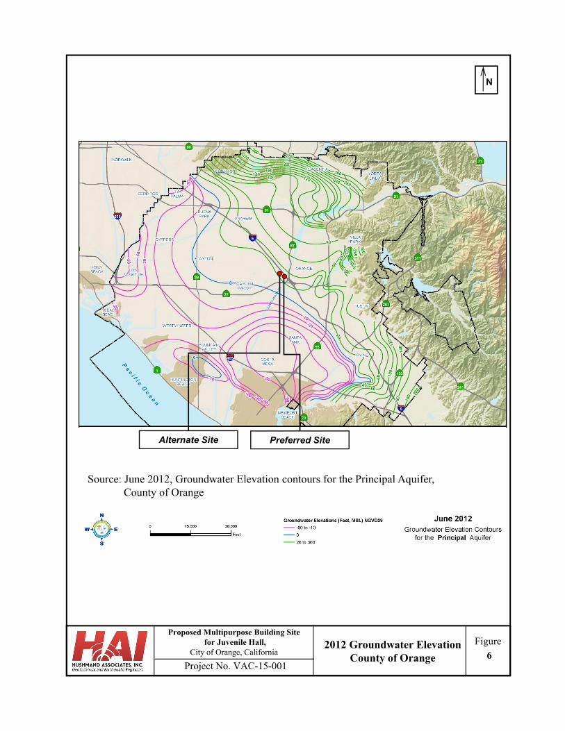
Project No. VAC-15-001
FigureProposed Multipurpose Building Site
for Juvenile Hall, City of Orange, California
N
Source: June 2012, Groundwater Elevation contours for the Principal Aquifer, County of Orange
2012 Groundwater Elevation County of Orange 6
Preferred SiteAlternate Site
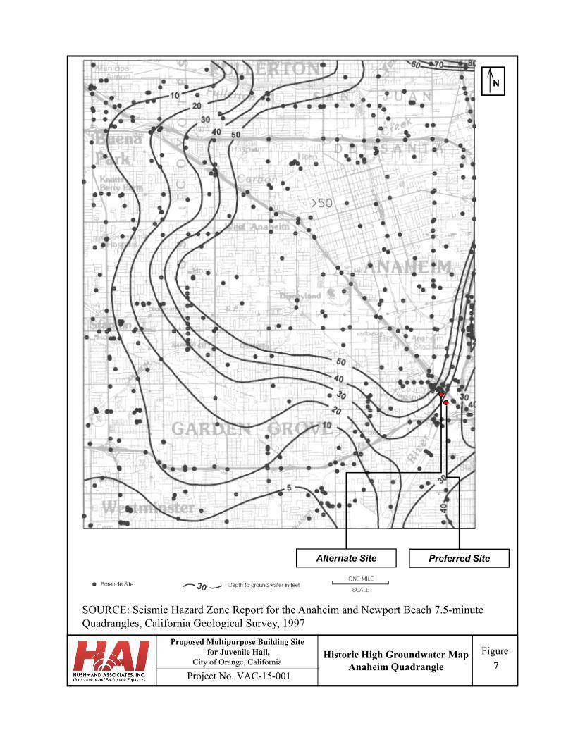
Project No. VAC-15-001
FigureProposed Multipurpose Building Site
for Juvenile Hall, City of Orange, California
N
Preferred Site
Historic High Groundwater Map Anaheim Quadrangle 7
Alternate Site
SOURCE: Seismic Hazard Zone Report for the Anaheim and Newport Beach 7.5-minute Quadrangles, California Geological Survey, 1997
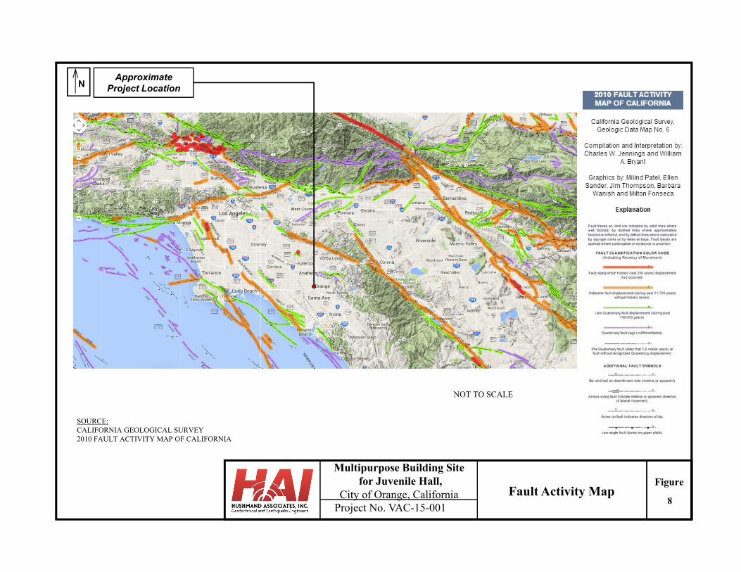
Project No. VAC-15-001
Multipurpose Building Sitefor Juvenile Hall,
City of Orange, CaliforniaFigure
Fault Activity Map8
NApproximate
Project Location
NOT TO SCALE
SOURCE:CALIFORNIA GEOLOGICAL SURVEY2010 FAULT ACTIVITY MAP OF CALIFORNIA
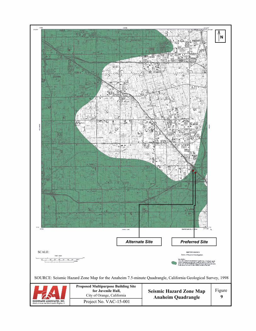
Project No. VAC-15-001
FigureProposed Multipurpose Building Site
for Juvenile Hall, City of Orange, California
N
SCALE:
SOURCE: Seismic Hazard Zone Map for the Anaheim 7.5-minute Quadrangle, California Geological Survey, 1998
Preferred SiteAlternate Site
9Seismic Hazard Zone Map
Anaheim Quadrangle
APPENDIX A LOGS OF CPT
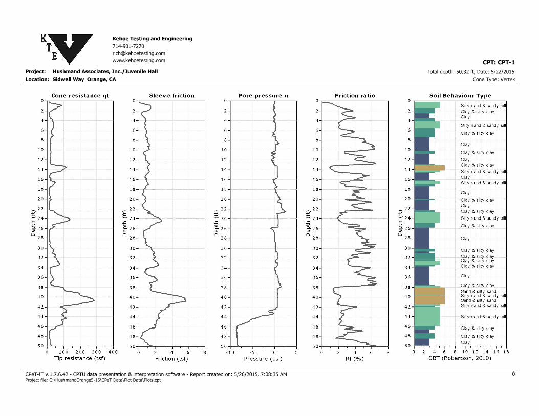
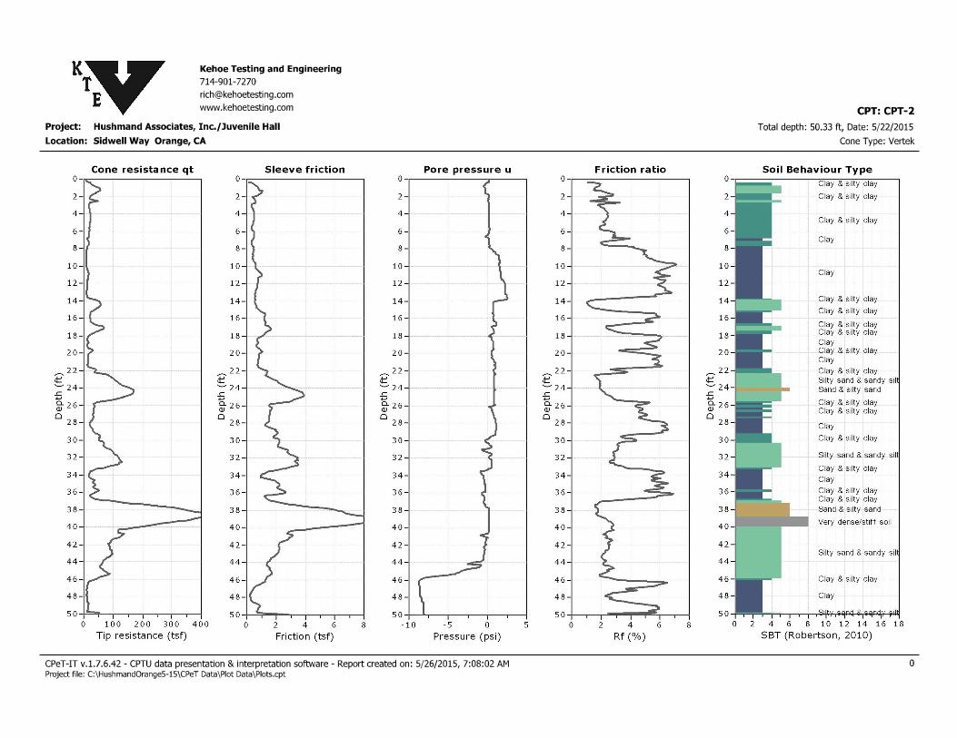
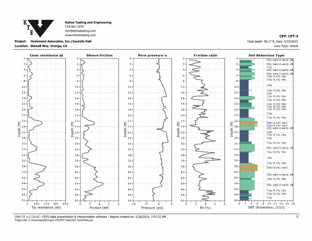
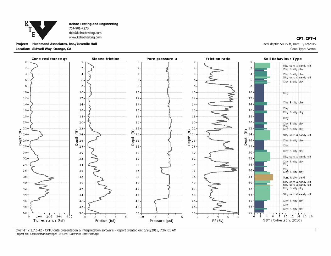
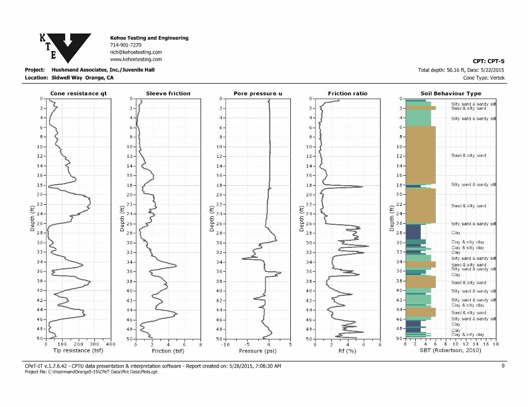
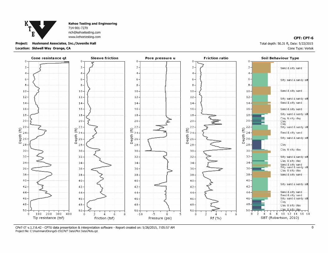
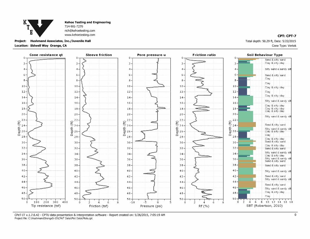
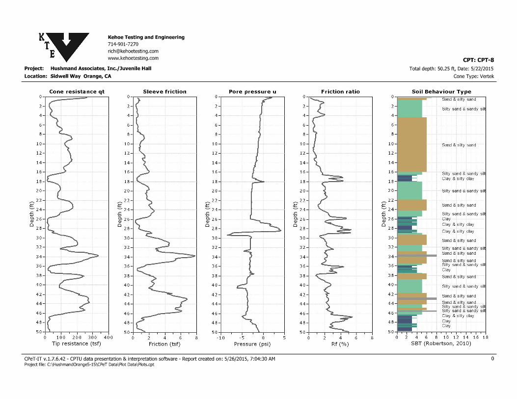
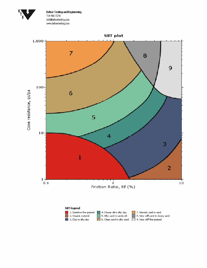
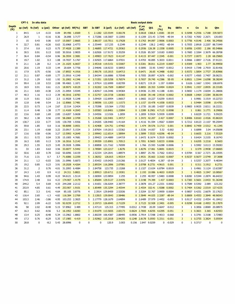
Depth
(ft)qc (tsf) fs (tsf) u (psi) Other qt (tsf) Rf(%) SBT Ic SBT ã (pcf) ó,v (tsf) u0 (tsf)
ó',vo
(tsf)Qt1
Fr
(%)Bq SBTn n Cn Ic Qtn
1 84.5 1.4 -0.33 0.09 84.496 1.6569 5 2.1282 123.5544 0.06178 0 0.0618 1366.8 1.6581 -3E-04 6 0.5098 4.2556 1.7188 339.5873
2 26.9 1 -0.16 0.36 26.898 3.7177 4 2.73286 118.3007 0.12093 0 0.1209 221.43 3.7345 -4E-04 8 0.7202 4.7692 2.2671 120.693
3 15 0.43 0.06 0.57 15.0007 2.8665 3 2.86157 110.7011 0.17628 0 0.1763 84.097 2.9006 0.0003 5 0.7756 4.0146 2.406 56.24566
4 32.7 0.81 -0.26 0.63 32.6968 2.4773 4 2.55449 117.235 0.2349 0 0.2349 138.2 2.4952 -6E-04 5 0.7055 2.8918 2.2207 88.71949
5 37.4 0.8 0.23 0.75 37.4028 2.1389 5 2.46895 117.4721 0.29363 0 0.2936 126.38 2.1558 0.0005 5 0.6956 2.4393 2.186 85.54866
6 30.5 0.91 0.13 0.83 30.5016 2.9835 4 2.62926 117.9172 0.35259 0 0.3526 85.507 3.0183 0.0003 5 0.7683 2.3264 2.3679 66.28708
7 36.4 0.84 -0.54 0.96 36.3934 2.3081 4 2.49903 117.7623 0.41147 0 0.4115 87.447 2.3345 -0.001 5 0.7377 2.0073 2.28 68.25865
8 19.7 1.02 0.3 1.08 19.7037 5.1767 3 2.92925 117.6864 0.47031 0 0.4703 40.895 5.3033 0.0011 3 0.9066 2.0857 2.7126 37.91221
9 21.1 1.28 0.2 1.34 21.1025 6.0657 3 2.95318 119.5151 0.53007 0 0.5301 38.811 6.2219 0.0007 3 0.9309 1.903 2.77 36.99958
10 20.6 1.19 0.33 1.44 20.604 5.7756 3 2.94646 118.9233 0.58953 0 0.5895 33.95 5.9457 0.0012 3 0.9419 1.7348 2.7919 32.81456
11 17.9 0.75 -0.56 1.56 17.8932 4.1916 3 2.90176 115.2015 0.64713 0 0.6471 26.65 4.3488 -0.002 3 0.9372 1.5854 2.7727 25.83966
12 21.1 0.87 -0.69 1.77 21.0916 4.1249 3 2.84244 116.6886 0.70548 0 0.7055 28.897 4.2676 -0.002 4 0.9277 1.4565 2.7407 28.06231
13 31.2 1.29 0.02 1.92 31.2002 4.1346 4 2.71551 120.5258 0.76574 0 0.7657 39.745 4.2386 5E-05 4 0.8921 1.3344 2.6398 38.38249
14 99.4 1.18 0.53 2.08 99.4065 1.1871 6 1.97914 122.6999 0.82709 0 0.8271 119.19 1.197 0.0004 6 0.626 1.1667 1.9341 108.6976
15 18.9 0.91 0.61 2.21 18.9075 4.8129 3 2.92202 116.7509 0.88547 0 0.8855 20.353 5.0494 0.0024 3 0.9941 1.1937 2.8935 20.33185
16 21.1 0.83 -0.38 2.25 21.0954 3.9345 3 2.82917 116.3446 0.94364 0 0.9436 21.355 4.1188 -0.001 3 0.9692 1.1174 2.8204 21.28006
17 40.3 1.16 0.13 2.39 40.3016 2.8783 4 2.52757 120.3728 1.00383 0 1.0038 39.148 2.9518 0.0002 4 0.8608 1.0464 2.5284 38.86194
18 11.9 0.61 0.23 2.5 11.9028 5.1248 3 3.09429 112.6954 1.06017 0 1.0602 10.227 5.6259 0.0015 3 1 0.9981 3.1519 10.22723
19 12.8 0.48 0.54 2.6 12.8066 3.7481 3 2.98596 111.1203 1.11573 0 1.1157 10.478 4.1058 0.0033 3 1 0.9484 3.0598 10.4782
20 22.5 0.73 1.14 2.67 22.514 3.2424 4 2.75398 115.564 1.17352 0 1.1735 18.185 3.4207 0.0039 3 0.9803 0.9035 2.8211 18.22221
21 11.4 0.48 1.38 2.77 11.4169 4.2043 3 3.05583 110.8401 1.22894 0 1.2289 8.2901 4.7115 0.0098 3 1 0.861 3.1771 8.29006
22 13.6 0.69 1.69 2.85 13.6207 5.0658 3 3.04556 113.926 1.2859 0 1.2859 9.5924 5.5939 0.0099 3 1 0.8229 3.1721 9.59235
23 58.2 1.38 0.56 2.93 58.2069 2.3709 5 2.35268 122.5401 1.34717 0 1.3472 42.207 2.427 0.0007 5 0.8406 0.8163 2.4326 43.86324
24 130.7 2.53 0.77 3.05 130.709 1.9356 5 2.04205 128.9483 1.41164 0 1.4116 91.594 1.9567 0.0004 5 0.7212 0.8123 2.1107 99.25944
25 59.8 1.85 0.8 3.16 59.8098 3.0931 5 2.42408 124.751 1.47402 0 1.474 39.576 3.1713 0.001 4 0.8842 0.7459 2.5312 41.1245
26 23.1 1.19 -0.68 3.22 23.0917 5.1534 3 2.87654 119.2013 1.53362 0 1.5336 14.057 5.52 -0.002 3 1 0.6899 3.04 14.05698
27 13.6 0.58 -0.06 3.27 13.5993 4.2649 3 2.99943 112.6514 1.58994 0 1.5899 7.5533 4.8296 -4E-04 3 1 0.6655 3.216 7.55329
28 15.1 0.72 0.04 3.35 15.1005 4.7681 3 2.99423 114.4889 1.64719 0 1.6472 8.1674 5.3519 0.0002 3 1 0.6424 3.2155 8.16743
29 16.3 0.85 0.13 3.39 16.3016 5.2142 3 2.99359 115.8901 1.70513 0 1.7051 8.5603 5.8233 0.0006 3 1 0.6205 3.2218 8.5603
30 29.3 1.55 0.23 3.45 29.3028 5.2896 3 2.80858 121.7162 1.76599 0 1.766 15.593 5.6288 0.0006 3 1 0.5992 3.0113 15.59283
31 33 1.83 0.63 3.56 33.0077 5.5442 3 2.78584 123.2217 1.8276 0 1.8276 17.061 5.8691 0.0015 3 1 0.579 2.9938 17.06065
32 50.6 1.83 0.78 3.62 50.6096 3.6159 4 2.52334 124.2641 1.88974 0 1.8897 25.781 3.7562 0.0012 4 0.9784 0.567 2.7271 26.10595
33 71.6 2.31 0.7 3.7 71.6086 3.2259 5 2.38252 126.815 1.95314 0 1.9531 35.663 3.3163 0.0007 4 0.9237 0.5677 2.5749 37.3698
34 21.1 1.2 -0.03 3.81 21.0996 5.6873 3 2.93432 119.0425 2.01266 0 2.0127 9.4834 6.287 -1E-04 3 1 0.5257 3.2077 9.48344
35 19.2 0.85 0.23 3.91 19.2028 4.4264 3 2.89334 116.2896 2.07081 0 2.0708 8.2731 4.9615 0.001 3 1 0.511 3.1912 8.2731
36 31.2 2 0.76 4.01 31.2093 6.4084 3 2.84758 123.735 2.13268 0 2.1327 13.634 6.8784 0.0019 3 1 0.4961 3.1124 13.63387
37 24.3 1.43 0.9 4.12 24.311 5.8821 3 2.89913 120.6711 2.19301 0 2.193 10.086 6.4653 0.0029 3 1 0.4825 3.1947 10.08567
38 94.6 1.43 0.99 4.22 94.6121 1.5114 5 2.06504 123.9854 2.255 0 2.255 40.957 1.5483 0.0008 5 0.8282 0.5344 2.2874 46.64222
39 174.9 2.48 0.6 4.22 174.907 1.4179 6 1.85694 129.5127 2.31976 0 2.3198 74.399 1.437 0.0003 5 0.7383 0.5601 2.0433 91.36348
40 244.2 5.4 0.69 4.33 244.208 2.2112 6 1.91651 136.0204 2.38777 0 2.3878 101.27 2.2331 0.0002 5 0.7589 0.5392 2.089 123.232
41 253.9 4.85 0.61 4.49 253.907 1.9101 6 1.85499 135.3294 2.45544 0 2.4554 102.41 1.9288 0.0002 5 0.7404 0.5362 2.0319 127.4235
42 85.1 3.3 0.41 4.64 85.105 3.8776 4 2.3914 129.8459 2.52036 0 2.5204 32.767 3.9959 0.0004 4 0.9857 0.4251 2.6679 33.17623
43 116.4 2.65 -1.3 4.82 116.384 2.2769 5 2.12815 129.0043 2.58486 0 2.5849 44.025 2.3287 -8E-04 5 0.8809 0.4553 2.3849 48.96543
44 103.3 2.46 -3.86 4.95 103.253 2.3825 5 2.17779 128.1679 2.64894 0 2.6489 37.979 2.4452 -0.003 5 0.9117 0.4332 2.4554 41.18412
45 92.1 2.09 -6.22 5.05 92.0239 2.2712 5 2.19713 126.6945 2.71229 0 2.7123 32.928 2.3401 -0.005 4 0.9298 0.4168 2.4953 35.17879
46 58 2.02 -8.48 5.15 57.8962 3.489 4 2.47114 125.315 2.77495 0.0312 2.7438 20.09 3.6647 -0.012 3 1 0.3856 2.8069 20.08975
47 16.3 0.62 -8.56 5.2 16.1952 3.8283 3 2.91079 113.5655 2.83173 0.0624 2.7693 4.8255 4.6395 -0.051 3 1 0.3821 3.365 4.82553
48 13.4 0.25 -8.48 5.34 13.2962 1.8802 4 2.80239 106.4387 2.88495 0.0936 2.7914 3.7298 2.4013 -0.068 3 1 0.3791 3.3108 3.72983
49 17.3 0.76 -8.29 5.35 17.1985 4.419 3 2.92962 115.2018 2.94255 0.1248 2.8178 5.0593 5.3311 -0.051 3 1 0.3755 3.3824 5.05934
50 28.8 0 -8.2 5.43 28.6996 0 0 0 120.9 3.003 0.156 2.847 9.0259 0 -0.029 0 1 0.3717 0 0
CPT-1 In situ data Basic output data
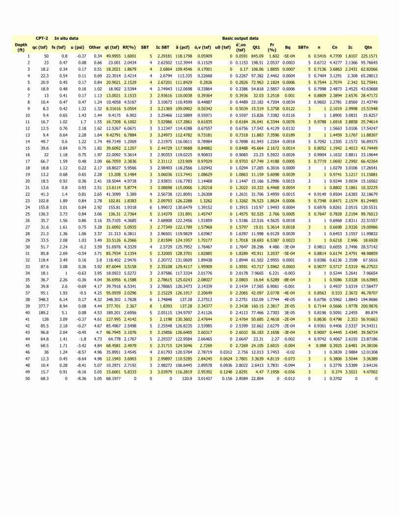
Depth
(ft)qc (tsf) fs (tsf) u (psi) Other qt (tsf) Rf(%) SBT Ic SBT ã (pcf) ó,v (tsf) u0 (tsf)
ó',vo
(tsf)Qt1
Fr
(%)Bq SBTn n Cn Ic Qtn
1 50 0.8 -0.37 0.34 49.9955 1.6001 5 2.29181 118.1798 0.05909 0 0.0591 845.09 1.602 -5E-04 6 0.5416 4.7709 1.8107 225.1571
2 23 0.47 0.08 0.66 23.001 2.0434 4 2.62502 112.3944 0.11529 0 0.1153 198.51 2.0537 0.0003 5 0.6712 4.4277 2.1366 95.76645
3 18.2 0.34 0.17 0.51 18.2021 1.8679 4 2.6864 109.4546 0.17001 0 0.17 106.06 1.8855 0.0007 5 0.7136 3.6863 2.2431 62.82066
4 22.3 0.54 0.11 0.69 22.3014 2.4214 4 2.6794 113.335 0.22668 0 0.2267 97.382 2.4462 0.0004 5 0.7404 3.1291 2.308 65.28013
5 20.9 0.45 0.17 0.84 20.9021 2.1529 4 2.67201 111.8429 0.2826 0 0.2826 72.963 2.1824 0.0006 5 0.7544 2.7074 2.342 52.75941
6 18.9 0.48 0.16 1.02 18.902 2.5394 4 2.74943 112.0698 0.33864 0 0.3386 54.818 2.5857 0.0006 5 0.7998 2.4873 2.4525 43.63668
7 13 0.41 0.17 1.13 13.0021 3.1533 3 2.93616 110.0038 0.39364 0 0.3936 32.03 3.2518 0.001 4 0.8809 2.3894 2.6576 28.47172
8 10.4 0.47 0.47 1.24 10.4058 4.5167 3 3.10673 110.4599 0.44887 0 0.4489 22.182 4.7204 0.0034 3 0.9602 2.2781 2.8569 21.43749
9 8.3 0.42 1.32 1.32 8.31616 5.0504 3 3.21369 109.0902 0.50342 0 0.5034 15.519 5.3758 0.0122 3 1 2.1019 2.9998 15.51948
10 9.4 0.65 1.43 1.44 9.4175 6.902 3 3.25466 112.5889 0.55971 0 0.5597 15.826 7.3382 0.0116 3 1 1.8905 3.0831 15.8257
11 16.7 1.02 1.7 1.55 16.7208 6.1002 3 3.02986 117.2861 0.61835 0 0.6184 26.041 6.3344 0.0076 3 0.9788 1.6918 2.8858 25.74614
12 12.5 0.76 2.18 1.62 12.5267 6.0671 3 3.12347 114.4288 0.67557 0 0.6756 17.542 6.4129 0.0132 3 1 1.5663 3.0106 17.54247
13 9.4 0.64 2.28 1.64 9.42791 6.7884 3 3.24973 112.4782 0.73181 0 0.7318 11.883 7.3596 0.0189 3 1 1.4459 3.1767 11.88307
14 49.7 0.6 1.22 1.74 49.7149 1.2069 5 2.21975 116.0611 0.78984 0 0.7898 61.943 1.2264 0.0018 5 0.7092 1.2305 2.1572 56.89375
15 39.6 0.84 0.75 1.82 39.6092 2.1207 5 2.44729 117.9688 0.84882 0 0.8488 45.664 2.1672 0.0014 5 0.8052 1.1942 2.4013 43.74449
16 22 1.18 0.75 1.97 22.0092 5.3614 3 2.90353 119.0225 0.90833 0 0.9083 23.23 5.5922 0.0026 3 0.9904 1.1632 2.8811 23.19644
17 66.7 1.59 0.48 2.09 66.7059 2.3836 5 2.31112 123.909 0.97029 0 0.9703 67.749 2.4188 0.0005 5 0.7719 1.0692 2.2992 66.42264
18 18.8 1.12 0.22 2.17 18.8027 5.9566 3 2.98493 118.2566 1.02942 0 1.0294 17.265 6.3016 0.0009 3 1 1.0279 3.0106 17.26541
19 13.2 0.68 0.65 2.28 13.208 5.1484 3 3.06036 113.7441 1.08629 0 1.0863 11.159 5.6098 0.0039 3 1 0.9741 3.1217 11.15881
20 18.5 0.92 0.36 2.41 18.5044 4.9718 3 2.93831 116.7783 1.14468 0 1.1447 15.166 5.2996 0.0015 3 1 0.9244 3.0034 15.16562
21 13.6 0.8 0.93 2.51 13.6114 5.8774 3 3.08698 115.0066 1.20218 0 1.2022 10.322 6.4468 0.0054 3 1 0.8802 3.1861 10.32225
22 41.3 1.4 0.81 2.65 41.3099 3.389 4 2.56738 121.8091 1.26308 0 1.2631 31.706 3.4959 0.0015 4 0.9149 0.8504 2.6383 32.18679
23 102.8 1.89 0.84 2.78 102.81 1.8383 5 2.09793 126.2288 1.3262 0 1.3262 76.523 1.8624 0.0006 5 0.7348 0.8471 2.1574 81.24485
24 155.8 3.01 0.84 2.92 155.81 1.9318 6 1.99072 130.6479 1.39152 0 1.3915 110.97 1.9493 0.0004 5 0.6976 0.8261 2.0515 120.5531
25 136.3 3.73 0.84 3.06 136.31 2.7364 5 2.14379 131.891 1.45747 0 1.4575 92.525 2.766 0.0005 5 0.7647 0.7828 2.2194 99.76513
26 35.7 1.56 0.86 3.16 35.7105 4.3685 4 2.68908 122.2456 1.51859 0 1.5186 22.516 4.5625 0.0018 3 1 0.6968 2.8311 22.51557
27 31.6 1.61 0.75 3.28 31.6092 5.0935 3 2.77349 122.1789 1.57968 0 1.5797 19.01 5.3614 0.0018 3 1 0.6698 2.9326 19.00986
28 21.3 1.36 1.06 3.37 21.313 6.3811 3 2.96501 119.9829 1.63967 0 1.6397 11.998 6.9129 0.0039 3 1 0.6453 3.1557 11.99832
29 33.5 2.08 1.03 3.49 33.5126 6.2066 3 2.81599 124.1957 1.70177 0 1.7018 18.693 6.5387 0.0023 3 1 0.6218 2.996 18.6928
30 51.7 2.24 -0.2 3.59 51.6976 4.3329 4 2.5729 125.7952 1.76467 0 1.7647 28.296 4.486 -3E-04 3 0.9811 0.6055 2.7496 28.57142
31 85.8 2.69 -0.54 3.71 85.7934 3.1354 5 2.32005 128.3701 1.82885 0 1.8289 45.911 3.2037 -5E-04 4 0.8814 0.6174 2.4791 48.98859
32 118.4 3.49 0.16 3.8 118.402 2.9476 5 2.20772 131.0609 1.89438 0 1.8944 61.502 2.9955 0.0001 5 0.8386 0.6136 2.3598 67.5616
33 87.6 3.08 0.36 3.92 87.6044 3.5158 5 2.35108 129.4117 1.95909 0 1.9591 43.717 3.5962 0.0003 4 0.9077 0.5717 2.5319 46.27522
34 18.1 1 -0.63 3.95 18.0923 5.5272 3 2.97586 117.3334 2.01776 0 2.0178 7.9665 6.221 -0.003 3 1 0.5244 3.2641 7.96654
35 36.7 2.26 -0.36 4.04 36.6956 6.1588 3 2.78615 125.0243 2.08027 0 2.0803 16.64 6.5289 -8E-04 3 1 0.5086 3.0328 16.63985
36 39.8 2.6 -0.69 4.17 39.7916 6.5341 3 2.78065 126.2473 2.14339 0 2.1434 17.565 6.9061 -0.001 3 1 0.4937 3.0319 17.56477
37 95.1 1.93 -0.5 4.25 95.0939 2.0296 5 2.15229 126.1917 2.20649 0 2.2065 42.097 2.0778 -4E-04 5 0.8563 0.533 2.3672 46.78707
38 348.3 6.14 0.17 4.32 348.302 1.7628 6 1.74848 137.28 2.27513 0 2.2751 152.09 1.7744 4E-05 6 0.6756 0.5962 1.8843 194.9686
39 377.7 8.94 0.08 4.44 377.701 2.367 8 1.8393 137.28 2.34377 0 2.3438 160.15 2.3817 2E-05 5 0.7144 0.5666 1.9778 200.9876
40 189.2 5.1 0.08 4.53 189.201 2.6956 5 2.05115 134.9797 2.41126 0 2.4113 77.466 2.7303 3E-05 5 0.8196 0.5091 2.2455 89.874
41 128 3.09 -0.37 4.61 127.995 2.4142 5 2.1198 130.3602 2.47644 0 2.4764 50.685 2.4618 -2E-04 5 0.8636 0.4798 2.353 56.91663
42 85.5 2.18 -0.27 4.67 85.4967 2.5498 5 2.25548 126.8235 2.53985 0 2.5399 32.662 2.6279 -2E-04 4 0.9361 0.4406 2.5337 34.54311
43 96.8 2.04 -0.45 4.7 96.7945 2.1076 5 2.15856 126.6405 2.60317 0 2.6032 36.183 2.1658 -3E-04 5 0.9007 0.4445 2.4345 39.56724
44 64.8 1.41 -1.8 4.73 64.778 2.1767 5 2.29337 122.9584 2.66465 0 2.6647 23.31 2.27 -0.002 4 0.9742 0.4067 2.6193 23.87186
45 68.5 1.71 -3.42 4.84 68.4581 2.4979 5 2.31715 124.5046 2.7269 0 2.7269 24.105 2.6015 -0.004 4 0.988 0.3925 2.6481 24.38106
46 36 1.24 -8.57 4.96 35.8951 3.4545 4 2.61793 120.5784 2.78719 0.0312 2.756 12.013 3.7453 -0.02 3 1 0.3839 2.9884 12.01308
47 12.3 0.45 -8.64 4.98 12.1943 3.6903 3 2.99897 110.5285 2.84245 0.0624 2.7801 3.3639 4.8119 -0.073 3 1 0.3806 3.5044 3.36389
48 10.4 0.28 -8.41 5.07 10.2971 2.7192 3 2.98272 106.6445 2.89578 0.0936 2.8022 2.6413 3.7831 -0.094 3 1 0.3776 3.5389 2.64126
49 15.7 0.91 -8.16 5.05 15.6001 5.8333 3 3.03979 116.2819 2.95392 0.1248 2.8291 4.47 7.1958 -0.056 3 1 0.374 3.5021 4.47002
50 68.3 0 -8.36 5.05 68.1977 0 0 0 120.9 3.01437 0.156 2.8584 22.804 0 -0.012 0 1 0.3702 0 0
CPT-2 In situ data Basic output data
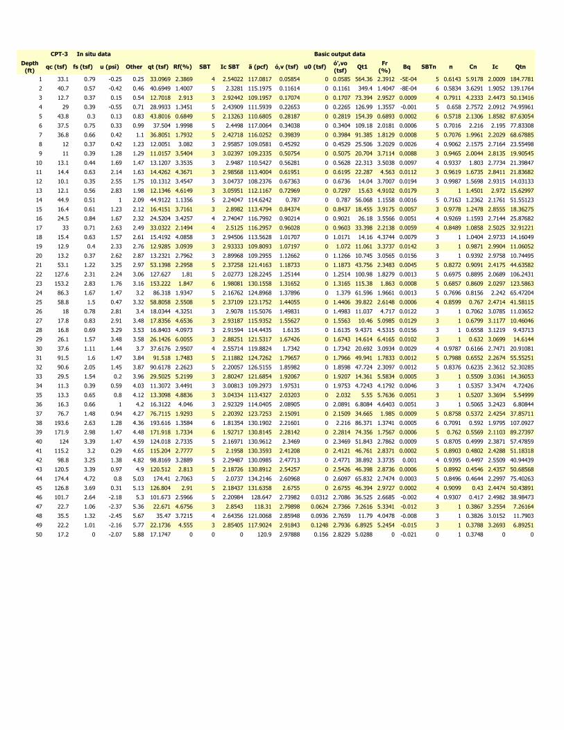
Depth
(ft)qc (tsf) fs (tsf) u (psi) Other qt (tsf) Rf(%) SBT Ic SBT ã (pcf) ó,v (tsf) u0 (tsf)
ó',vo
(tsf)Qt1
Fr
(%)Bq SBTn n Cn Ic Qtn
1 33.1 0.79 -0.25 0.25 33.0969 2.3869 4 2.54022 117.0817 0.05854 0 0.0585 564.36 2.3912 -5E-04 5 0.6143 5.9178 2.0009 184.7781
2 40.7 0.57 -0.42 0.46 40.6949 1.4007 5 2.3281 115.1975 0.11614 0 0.1161 349.4 1.4047 -8E-04 6 0.5834 3.6291 1.9052 139.1764
3 12.7 0.37 0.15 0.54 12.7018 2.913 3 2.92442 109.1957 0.17074 0 0.1707 73.394 2.9527 0.0009 4 0.7911 4.2333 2.4473 50.13416
4 29 0.39 -0.55 0.71 28.9933 1.3451 5 2.43909 111.5939 0.22653 0 0.2265 126.99 1.3557 -0.001 5 0.658 2.7572 2.0912 74.95961
5 43.8 0.3 0.13 0.83 43.8016 0.6849 5 2.13263 110.6805 0.28187 0 0.2819 154.39 0.6893 0.0002 6 0.5718 2.1306 1.8582 87.63054
6 37.5 0.75 0.33 0.99 37.504 1.9998 5 2.4498 117.0064 0.34038 0 0.3404 109.18 2.0181 0.0006 5 0.7016 2.216 2.195 77.83308
7 36.8 0.66 0.42 1.1 36.8051 1.7932 5 2.42718 116.0252 0.39839 0 0.3984 91.385 1.8129 0.0008 5 0.7076 1.9961 2.2029 68.67885
8 12 0.37 0.42 1.23 12.0051 3.082 3 2.95857 109.0581 0.45292 0 0.4529 25.506 3.2029 0.0026 4 0.9062 2.1575 2.7164 23.55498
9 11 0.39 1.28 1.29 11.0157 3.5404 3 3.02397 109.2335 0.50754 0 0.5075 20.704 3.7114 0.0088 3 0.9465 2.0044 2.8135 19.90545
10 13.1 0.44 1.69 1.47 13.1207 3.3535 3 2.9487 110.5427 0.56281 0 0.5628 22.313 3.5038 0.0097 4 0.9337 1.803 2.7734 21.39847
11 14.4 0.63 2.14 1.63 14.4262 4.3671 3 2.98568 113.4004 0.61951 0 0.6195 22.287 4.563 0.0112 3 0.9619 1.6735 2.8411 21.83682
12 10.1 0.35 2.55 1.75 10.1312 3.4547 3 3.04737 108.2376 0.67363 0 0.6736 14.04 3.7007 0.0194 3 0.9987 1.5698 2.9315 14.03133
13 12.1 0.56 2.83 1.98 12.1346 4.6149 3 3.05951 112.1167 0.72969 0 0.7297 15.63 4.9102 0.0179 3 1 1.4501 2.972 15.62997
14 44.9 0.51 1 2.09 44.9122 1.1356 5 2.24047 114.6242 0.787 0 0.787 56.068 1.1558 0.0016 5 0.7163 1.2362 2.1761 51.55123
15 16.4 0.61 1.23 2.12 16.4151 3.7161 3 2.8982 113.4794 0.84374 0 0.8437 18.455 3.9175 0.0057 3 0.9778 1.2478 2.8555 18.36275
16 24.5 0.84 1.67 2.32 24.5204 3.4257 4 2.74047 116.7992 0.90214 0 0.9021 26.18 3.5566 0.0051 4 0.9269 1.1593 2.7144 25.87682
17 33 0.71 2.63 2.49 33.0322 2.1494 4 2.5125 116.2957 0.96028 0 0.9603 33.398 2.2138 0.0059 4 0.8489 1.0858 2.5025 32.91221
18 15.4 0.63 1.57 2.61 15.4192 4.0858 3 2.94506 113.5628 1.01707 0 1.0171 14.16 4.3744 0.0079 3 1 1.0404 2.9733 14.16049
19 12.9 0.4 2.33 2.76 12.9285 3.0939 3 2.93333 109.8093 1.07197 0 1.072 11.061 3.3737 0.0142 3 1 0.9871 2.9904 11.06052
20 13.2 0.37 2.62 2.87 13.2321 2.7962 3 2.89968 109.2955 1.12662 0 1.1266 10.745 3.0565 0.0156 3 1 0.9392 2.9758 10.74495
21 53.1 1.22 3.25 2.97 53.1398 2.2958 5 2.37258 121.4163 1.18733 0 1.1873 43.756 2.3483 0.0045 5 0.8272 0.9091 2.4175 44.63582
22 127.6 2.31 2.24 3.06 127.627 1.81 5 2.02773 128.2245 1.25144 0 1.2514 100.98 1.8279 0.0013 5 0.6975 0.8895 2.0689 106.2431
23 153.2 2.83 1.76 3.16 153.222 1.847 6 1.98081 130.1558 1.31652 0 1.3165 115.38 1.863 0.0008 5 0.6857 0.8609 2.0297 123.5863
24 86.3 1.67 1.47 3.2 86.318 1.9347 5 2.16762 124.8968 1.37896 0 1.379 61.596 1.9661 0.0013 5 0.7696 0.8156 2.242 65.47204
25 58.8 1.5 0.47 3.32 58.8058 2.5508 5 2.37109 123.1752 1.44055 0 1.4406 39.822 2.6148 0.0006 4 0.8599 0.767 2.4714 41.58115
26 18 0.78 2.81 3.4 18.0344 4.3251 3 2.9078 115.5076 1.49831 0 1.4983 11.037 4.717 0.0122 3 1 0.7062 3.0785 11.03652
27 17.8 0.83 2.91 3.48 17.8356 4.6536 3 2.93187 115.9352 1.55627 0 1.5563 10.46 5.0985 0.0129 3 1 0.6799 3.1177 10.46046
28 16.8 0.69 3.29 3.53 16.8403 4.0973 3 2.91594 114.4435 1.6135 0 1.6135 9.4371 4.5315 0.0156 3 1 0.6558 3.1219 9.43713
29 26.1 1.57 3.48 3.58 26.1426 6.0055 3 2.88251 121.5317 1.67426 0 1.6743 14.614 6.4165 0.0102 3 1 0.632 3.0699 14.6144
30 37.6 1.11 1.44 3.7 37.6176 2.9507 4 2.55714 119.8824 1.7342 0 1.7342 20.692 3.0934 0.0029 4 0.9787 0.6166 2.7471 20.91081
31 91.5 1.6 1.47 3.84 91.518 1.7483 5 2.11882 124.7262 1.79657 0 1.7966 49.941 1.7833 0.0012 5 0.7988 0.6552 2.2674 55.55251
32 90.6 2.05 1.45 3.87 90.6178 2.2623 5 2.20057 126.5155 1.85982 0 1.8598 47.724 2.3097 0.0012 5 0.8376 0.6235 2.3612 52.30285
33 29.5 1.54 0.2 3.96 29.5025 5.2199 3 2.80247 121.6854 1.92067 0 1.9207 14.361 5.5834 0.0005 3 1 0.5509 3.0361 14.36053
34 11.3 0.39 0.59 4.03 11.3072 3.4491 3 3.00813 109.2973 1.97531 0 1.9753 4.7243 4.1792 0.0046 3 1 0.5357 3.3474 4.72426
35 13.3 0.65 0.8 4.12 13.3098 4.8836 3 3.04334 113.4327 2.03203 0 2.032 5.55 5.7636 0.0051 3 1 0.5207 3.3694 5.54999
36 16.3 0.66 1 4.2 16.3122 4.046 3 2.92329 114.0405 2.08905 0 2.0891 6.8084 4.6403 0.0051 3 1 0.5065 3.2423 6.80844
37 76.7 1.48 0.94 4.27 76.7115 1.9293 5 2.20392 123.7253 2.15091 0 2.1509 34.665 1.985 0.0009 5 0.8758 0.5372 2.4254 37.85711
38 193.6 2.63 1.28 4.36 193.616 1.3584 6 1.81354 130.1902 2.21601 0 2.216 86.371 1.3741 0.0005 6 0.7091 0.592 1.9795 107.0927
39 171.9 2.98 1.47 4.48 171.918 1.7334 6 1.92717 130.8145 2.28142 0 2.2814 74.356 1.7567 0.0006 5 0.762 0.5569 2.1103 89.27397
40 124 3.39 1.47 4.59 124.018 2.7335 5 2.16971 130.9612 2.3469 0 2.3469 51.843 2.7862 0.0009 5 0.8705 0.4999 2.3871 57.47859
41 115.2 3.2 0.29 4.65 115.204 2.7777 5 2.1958 130.3593 2.41208 0 2.4121 46.761 2.8371 0.0002 5 0.8903 0.4802 2.4288 51.18318
42 98.8 3.25 1.38 4.82 98.8169 3.2889 5 2.29487 130.0985 2.47713 0 2.4771 38.892 3.3735 0.001 4 0.9395 0.4497 2.5509 40.94439
43 120.5 3.39 0.97 4.9 120.512 2.813 5 2.18726 130.8912 2.54257 0 2.5426 46.398 2.8736 0.0006 5 0.8992 0.4546 2.4357 50.68568
44 174.4 4.72 0.8 5.03 174.41 2.7063 5 2.0737 134.2146 2.60968 0 2.6097 65.832 2.7474 0.0003 5 0.8496 0.4644 2.2997 75.40263
45 126.8 3.69 0.31 5.13 126.804 2.91 5 2.18437 131.6358 2.6755 0 2.6755 46.394 2.9727 0.0002 4 0.9099 0.43 2.4474 50.43891
46 101.7 2.64 -2.18 5.3 101.673 2.5966 5 2.20984 128.647 2.73982 0.0312 2.7086 36.525 2.6685 -0.002 4 0.9307 0.417 2.4982 38.98473
47 22.7 1.06 -2.37 5.36 22.671 4.6756 3 2.8543 118.31 2.79898 0.0624 2.7366 7.2616 5.3341 -0.012 3 1 0.3867 3.2554 7.26164
48 35.5 1.32 -2.45 5.67 35.47 3.7215 4 2.64356 121.0068 2.85948 0.0936 2.7659 11.79 4.0478 -0.008 3 1 0.3826 3.0152 11.7903
49 22.2 1.01 -2.16 5.77 22.1736 4.555 3 2.85405 117.9024 2.91843 0.1248 2.7936 6.8925 5.2454 -0.015 3 1 0.3788 3.2693 6.89251
50 17.2 0 -2.07 5.88 17.1747 0 0 0 120.9 2.97888 0.156 2.8229 5.0288 0 -0.021 0 1 0.3748 0 0
CPT-3 In situ data Basic output data
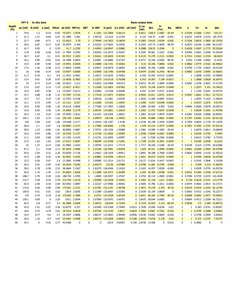
Depth
(ft)qc (tsf) fs (tsf) u (psi) Other qt (tsf) Rf(%) SBT Ic SBT ã (pcf) ó,v (tsf) u0 (tsf)
ó',vo
(tsf)Qt1
Fr
(%)Bq SBTn n Cn Ic Qtn
1 79.6 1.2 -0.19 -0.05 79.5977 1.5076 5 2.1201 122.2809 0.06114 0 0.0611 1300.9 1.5087 -2E-04 6 0.5039 4.2068 1.7021 316.217
2 51.2 1.27 -0.94 0.07 51.1885 2.481 5 2.40718 121.619 0.12195 0 0.122 418.75 2.487 -0.001 5 0.6237 3.8479 2.0133 185.7075
3 22.7 0.86 -0.71 0.2 22.6913 3.79 3 2.79446 116.7823 0.18034 0 0.1803 124.82 3.8204 -0.002 4 0.7636 3.8616 2.3805 82.15535
4 35.6 0.87 -0.17 0.25 35.5979 2.444 4 2.52223 117.9652 0.23932 0 0.2393 147.74 2.4605 -4E-04 5 0.6973 2.8194 2.1984 94.21357
5 41.7 0.95 0 0.35 41.7 2.2782 5 2.44993 118.9947 0.29882 0 0.2988 138.55 2.2946 0 5 0.6926 2.4007 2.1772 93.93204
6 17.8 0.58 -0.38 0.43 17.7954 3.2593 3 2.83553 113.3073 0.35547 0 0.3555 49.061 3.3257 -0.002 4 0.8364 2.4901 2.5459 41.04164
7 30.7 0.67 0.1 0.51 30.7012 2.1823 4 2.54161 115.6929 0.41332 0 0.4133 73.279 2.2121 0.0002 5 0.7513 2.0263 2.3154 58.0019
8 16.2 0.95 -0.02 0.62 16.1998 5.8643 3 3.02891 116.6886 0.47167 0 0.4717 33.346 6.0402 -9E-05 3 0.942 2.1406 2.8062 31.8191
9 14.5 0.99 -0.48 0.64 14.4941 6.8304 3 3.10889 116.7191 0.53002 0 0.53 26.346 7.0896 -0.002 3 0.9862 1.9774 2.9162 26.09602
10 17.9 1.26 -0.38 0.72 17.8954 7.0409 3 3.04971 118.9978 0.58952 0 0.5895 29.356 7.2808 -0.002 3 0.9799 1.7739 2.8923 29.01259
11 16 0.96 -0.19 0.82 15.9977 6.0009 3 3.03959 116.7346 0.64789 0 0.6479 23.692 6.2542 -9E-04 3 0.9892 1.6245 2.9095 23.56653
12 11.7 0.76 0.1 0.9 11.7012 6.4951 3 3.16517 114.2625 0.70502 0 0.705 15.597 6.9115 0.0007 3 1 1.5008 3.0702 15.59695
13 13.4 0.91 0.29 0.97 13.4036 6.7893 3 3.13275 115.9118 0.76298 0 0.763 16.567 7.199 0.0017 3 1 1.3868 3.0628 16.56741
14 33 0.73 0.19 1.08 33.0023 2.212 4 2.52053 116.4968 0.82123 0 0.8212 39.187 2.2684 0.0004 5 0.8282 1.2336 2.4651 37.51705
15 13.4 0.87 0.14 1.19 13.4017 6.4917 3 3.12008 115.5825 0.87902 0 0.879 14.246 6.9474 0.0008 3 1 1.2037 3.101 14.24623
16 15.5 0.87 0.38 1.3 15.5047 5.6112 3 3.03083 115.938 0.93699 0 0.937 15.547 5.9721 0.0019 3 1 1.1293 3.0291 15.54735
17 23.7 0.88 0.38 1.32 23.7047 3.7124 4 2.77416 117.0571 0.99552 0 0.9955 22.811 3.8751 0.0012 4 0.9567 1.0601 2.7811 22.75122
18 12.7 0.7 0.19 1.39 12.7023 5.5108 3 3.09218 113.861 1.05245 0 1.0525 11.069 6.0087 0.0012 3 1 1.0054 3.1433 11.06934
19 12.1 0.73 0.99 1.37 12.1121 6.027 3 3.13286 114.052 1.10947 0 1.1095 9.917 6.6348 0.0065 3 1 0.9537 3.2075 9.91701
20 24.6 0.96 0.96 1.36 24.6118 3.9006 4 2.77568 117.7853 1.16836 0 1.1684 20.065 4.095 0.003 3 0.9864 0.9069 2.8378 20.09219
21 15.9 0.83 0.56 1.45 15.9069 5.2179 3 3.00191 115.6561 1.22619 0 1.2262 11.973 5.6537 0.0028 3 1 0.8629 3.1001 11.97256
22 35.4 1.19 0.32 1.59 35.4039 3.3612 4 2.61441 120.2436 1.28631 0 1.2863 26.524 3.4879 0.0007 4 0.9383 0.8326 2.6968 26.84501
23 105.1 1.93 0.74 1.62 105.109 1.8362 5 2.09079 126.436 1.34953 0 1.3495 76.886 1.8601 0.0005 5 0.7347 0.8363 2.1541 82.01126
24 129 2.99 0.67 1.66 129.008 2.3177 5 2.10419 130.1387 1.4146 0 1.4146 90.198 2.3434 0.0004 5 0.7454 0.8054 2.1739 97.11878
25 94.9 2.1 0.67 1.8 94.9082 2.2127 5 2.17966 126.8046 1.478 0 1.478 63.214 2.2477 0.0005 5 0.7851 0.7692 2.2701 67.92132
26 30.9 1.23 -0.06 1.91 30.8993 3.9807 4 2.70751 120.1536 1.53808 0 1.5381 19.089 4.1892 -2E-04 3 1 0.6879 2.8611 19.08949
27 10.5 0.54 0.86 1.97 10.5105 5.1377 3 3.13738 111.5002 1.59383 0 1.5938 5.5945 6.0561 0.0069 3 1 0.6639 3.3793 5.5945
28 11.1 0.59 0.86 2.05 11.1105 5.3103 3 3.12731 112.2835 1.64997 0 1.65 5.7338 6.2364 0.0066 3 1 0.6413 3.3782 5.73376
29 27.4 1.62 1.04 2.05 27.4127 5.9097 3 2.86284 121.8768 1.71091 0 1.7109 15.022 6.3031 0.0029 3 1 0.6185 3.0558 15.0223
30 52 1.27 -0.14 2.06 51.9983 2.4424 5 2.39756 121.6572 1.77174 0 1.7717 28.349 2.5285 -2E-04 4 0.9149 0.624 2.5744 29.61986
31 87.2 2.1 0.28 2.13 87.2034 2.4082 5 2.23166 126.5981 1.83504 0 1.835 46.521 2.4599 0.0002 5 0.8481 0.6269 2.3904 50.57948
32 93.6 2.54 0.31 2.26 93.6038 2.7136 5 2.24821 128.1628 1.89912 0 1.8991 48.288 2.7698 0.0002 5 0.8602 0.6046 2.4142 52.40216
33 42.5 1.88 0.25 2.36 42.5031 4.4232 4 2.63881 124.0356 1.96114 0 1.9611 20.673 4.6372 0.0004 3 1 0.5395 2.8636 20.67265
34 12.3 0.56 0.67 2.4 12.3082 4.5498 3 3.05085 112.1514 2.01721 0 2.0172 5.1016 5.4417 0.0047 3 1 0.5245 3.3846 5.10158
35 26.4 2.01 -2.99 2.42 26.3634 7.6242 3 2.95275 123.36 2.07889 0 2.0789 11.681 8.2769 -0.009 3 1 0.509 3.216 11.68146
36 38.5 2.78 -2.58 2.52 38.4684 7.2267 3 2.82275 126.6546 2.14222 0 2.1422 16.957 7.6529 -0.005 3 1 0.4939 3.0735 16.95726
37 95.9 1.76 -1.44 2.57 95.8824 1.8356 5 2.11899 125.5372 2.20499 0 2.205 42.484 1.8788 -0.001 5 0.8431 0.5385 2.3328 47.67116
38 188.7 2.79 0.29 2.65 188.704 1.4785 6 1.8485 130.5597 2.27027 0 2.2703 82.119 1.4965 0.0001 6 0.7284 0.5735 2.0233 101.0428
39 215.7 3.48 0.29 2.78 215.704 1.6133 6 1.83999 132.5028 2.33652 0 2.3365 91.318 1.631 0.0001 6 0.728 0.5618 2.0141 113.2778
40 83.5 2.58 0.34 2.84 83.5042 3.0897 5 2.32327 127.9986 2.40052 0 2.4005 33.786 3.1811 0.0003 4 0.9474 0.4602 2.5814 35.27271
41 175.6 4.06 0.09 2.89 175.601 2.3121 5 2.01781 133.1291 2.46708 0 2.4671 70.178 2.345 4E-05 5 0.8143 0.5019 2.2245 82.12746
42 159.9 4.51 0.01 3.03 159.9 2.8205 5 2.11089 133.6697 2.53392 0 2.5339 62.104 2.8659 0 5 0.8592 0.4722 2.3343 70.22717
43 175 4.74 0.19 3.18 175.002 2.7085 5 2.0731 134.2538 2.60105 0 2.6011 66.282 2.7494 8E-05 5 0.8485 0.4662 2.2977 75.95923
44 159.1 4.08 0 3.26 159.1 2.5644 5 2.07969 132.9243 2.66751 0 2.6675 58.644 2.6082 0 5 0.8604 0.4513 2.3208 66.72211
45 92.4 2.8 -0.77 3.4 92.3906 3.0306 5 2.28752 128.844 2.73193 0 2.7319 32.819 3.123 -6E-04 4 0.9659 0.4 2.589 33.89733
46 43.9 1.91 -5.07 3.56 43.8379 4.357 4 2.62469 124.2268 2.79404 0.0312 2.7628 14.856 4.6536 -0.01 3 1 0.383 2.9741 14.85567
47 18.8 0.75 -4.79 3.63 18.7414 4.0018 3 2.87345 115.3144 2.8517 0.0624 2.7893 5.6967 4.7201 -0.026 3 1 0.3794 3.3098 5.69665
48 19.4 0.77 -4.6 3.7 19.3437 3.9806 3 2.86137 115.5842 2.90949 0.0936 2.8159 5.8362 4.6854 -0.026 3 1 0.3758 3.2994 5.83623
49 25.6 1.16 -4.4 3.67 25.5461 4.5408 3 2.80714 119.2609 2.96912 0.1248 2.8443 7.9376 5.138 -0.02 3 1 0.372 3.2147 7.93757
50 43.1 0 -4.35 3.77 43.0468 0 0 0 120.9 3.02957 0.156 2.8736 13.926 0 -0.012 0 1 0.3682 0 0
CPT-4 In situ data Basic output data
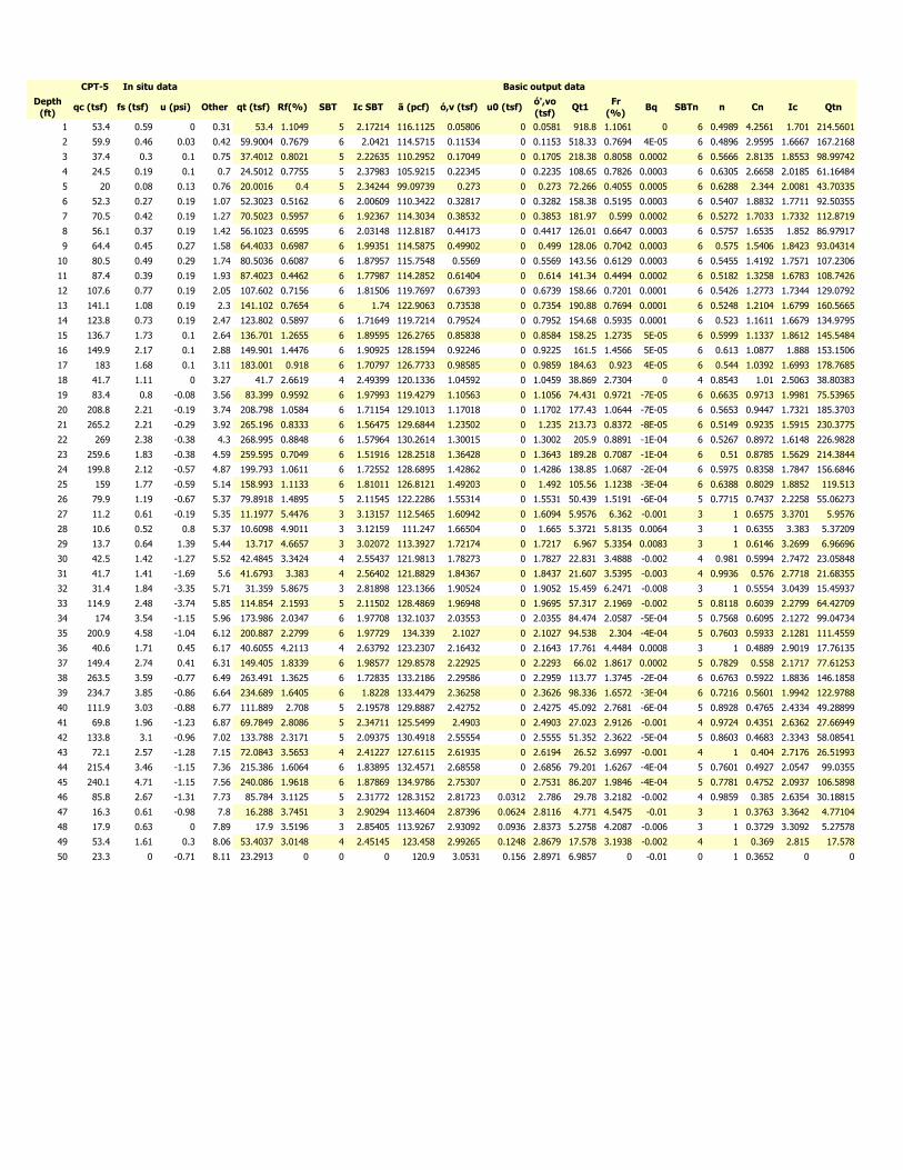
Depth
(ft)qc (tsf) fs (tsf) u (psi) Other qt (tsf) Rf(%) SBT Ic SBT ã (pcf) ó,v (tsf) u0 (tsf)
ó',vo
(tsf)Qt1
Fr
(%)Bq SBTn n Cn Ic Qtn
1 53.4 0.59 0 0.31 53.4 1.1049 5 2.17214 116.1125 0.05806 0 0.0581 918.8 1.1061 0 6 0.4989 4.2561 1.701 214.5601
2 59.9 0.46 0.03 0.42 59.9004 0.7679 6 2.0421 114.5715 0.11534 0 0.1153 518.33 0.7694 4E-05 6 0.4896 2.9595 1.6667 167.2168
3 37.4 0.3 0.1 0.75 37.4012 0.8021 5 2.22635 110.2952 0.17049 0 0.1705 218.38 0.8058 0.0002 6 0.5666 2.8135 1.8553 98.99742
4 24.5 0.19 0.1 0.7 24.5012 0.7755 5 2.37983 105.9215 0.22345 0 0.2235 108.65 0.7826 0.0003 6 0.6305 2.6658 2.0185 61.16484
5 20 0.08 0.13 0.76 20.0016 0.4 5 2.34244 99.09739 0.273 0 0.273 72.266 0.4055 0.0005 6 0.6288 2.344 2.0081 43.70335
6 52.3 0.27 0.19 1.07 52.3023 0.5162 6 2.00609 110.3422 0.32817 0 0.3282 158.38 0.5195 0.0003 6 0.5407 1.8832 1.7711 92.50355
7 70.5 0.42 0.19 1.27 70.5023 0.5957 6 1.92367 114.3034 0.38532 0 0.3853 181.97 0.599 0.0002 6 0.5272 1.7033 1.7332 112.8719
8 56.1 0.37 0.19 1.42 56.1023 0.6595 6 2.03148 112.8187 0.44173 0 0.4417 126.01 0.6647 0.0003 6 0.5757 1.6535 1.852 86.97917
9 64.4 0.45 0.27 1.58 64.4033 0.6987 6 1.99351 114.5875 0.49902 0 0.499 128.06 0.7042 0.0003 6 0.575 1.5406 1.8423 93.04314
10 80.5 0.49 0.29 1.74 80.5036 0.6087 6 1.87957 115.7548 0.5569 0 0.5569 143.56 0.6129 0.0003 6 0.5455 1.4192 1.7571 107.2306
11 87.4 0.39 0.19 1.93 87.4023 0.4462 6 1.77987 114.2852 0.61404 0 0.614 141.34 0.4494 0.0002 6 0.5182 1.3258 1.6783 108.7426
12 107.6 0.77 0.19 2.05 107.602 0.7156 6 1.81506 119.7697 0.67393 0 0.6739 158.66 0.7201 0.0001 6 0.5426 1.2773 1.7344 129.0792
13 141.1 1.08 0.19 2.3 141.102 0.7654 6 1.74 122.9063 0.73538 0 0.7354 190.88 0.7694 0.0001 6 0.5248 1.2104 1.6799 160.5665
14 123.8 0.73 0.19 2.47 123.802 0.5897 6 1.71649 119.7214 0.79524 0 0.7952 154.68 0.5935 0.0001 6 0.523 1.1611 1.6679 134.9795
15 136.7 1.73 0.1 2.64 136.701 1.2655 6 1.89595 126.2765 0.85838 0 0.8584 158.25 1.2735 5E-05 6 0.5999 1.1337 1.8612 145.5484
16 149.9 2.17 0.1 2.88 149.901 1.4476 6 1.90925 128.1594 0.92246 0 0.9225 161.5 1.4566 5E-05 6 0.613 1.0877 1.888 153.1506
17 183 1.68 0.1 3.11 183.001 0.918 6 1.70797 126.7733 0.98585 0 0.9859 184.63 0.923 4E-05 6 0.544 1.0392 1.6993 178.7685
18 41.7 1.11 0 3.27 41.7 2.6619 4 2.49399 120.1336 1.04592 0 1.0459 38.869 2.7304 0 4 0.8543 1.01 2.5063 38.80383
19 83.4 0.8 -0.08 3.56 83.399 0.9592 6 1.97993 119.4279 1.10563 0 1.1056 74.431 0.9721 -7E-05 6 0.6635 0.9713 1.9981 75.53965
20 208.8 2.21 -0.19 3.74 208.798 1.0584 6 1.71154 129.1013 1.17018 0 1.1702 177.43 1.0644 -7E-05 6 0.5653 0.9447 1.7321 185.3703
21 265.2 2.21 -0.29 3.92 265.196 0.8333 6 1.56475 129.6844 1.23502 0 1.235 213.73 0.8372 -8E-05 6 0.5149 0.9235 1.5915 230.3775
22 269 2.38 -0.38 4.3 268.995 0.8848 6 1.57964 130.2614 1.30015 0 1.3002 205.9 0.8891 -1E-04 6 0.5267 0.8972 1.6148 226.9828
23 259.6 1.83 -0.38 4.59 259.595 0.7049 6 1.51916 128.2518 1.36428 0 1.3643 189.28 0.7087 -1E-04 6 0.51 0.8785 1.5629 214.3844
24 199.8 2.12 -0.57 4.87 199.793 1.0611 6 1.72552 128.6895 1.42862 0 1.4286 138.85 1.0687 -2E-04 6 0.5975 0.8358 1.7847 156.6846
25 159 1.77 -0.59 5.14 158.993 1.1133 6 1.81011 126.8121 1.49203 0 1.492 105.56 1.1238 -3E-04 6 0.6388 0.8029 1.8852 119.513
26 79.9 1.19 -0.67 5.37 79.8918 1.4895 5 2.11545 122.2286 1.55314 0 1.5531 50.439 1.5191 -6E-04 5 0.7715 0.7437 2.2258 55.06273
27 11.2 0.61 -0.19 5.35 11.1977 5.4476 3 3.13157 112.5465 1.60942 0 1.6094 5.9576 6.362 -0.001 3 1 0.6575 3.3701 5.9576
28 10.6 0.52 0.8 5.37 10.6098 4.9011 3 3.12159 111.247 1.66504 0 1.665 5.3721 5.8135 0.0064 3 1 0.6355 3.383 5.37209
29 13.7 0.64 1.39 5.44 13.717 4.6657 3 3.02072 113.3927 1.72174 0 1.7217 6.967 5.3354 0.0083 3 1 0.6146 3.2699 6.96696
30 42.5 1.42 -1.27 5.52 42.4845 3.3424 4 2.55437 121.9813 1.78273 0 1.7827 22.831 3.4888 -0.002 4 0.981 0.5994 2.7472 23.05848
31 41.7 1.41 -1.69 5.6 41.6793 3.383 4 2.56402 121.8829 1.84367 0 1.8437 21.607 3.5395 -0.003 4 0.9936 0.576 2.7718 21.68355
32 31.4 1.84 -3.35 5.71 31.359 5.8675 3 2.81898 123.1366 1.90524 0 1.9052 15.459 6.2471 -0.008 3 1 0.5554 3.0439 15.45937
33 114.9 2.48 -3.74 5.85 114.854 2.1593 5 2.11502 128.4869 1.96948 0 1.9695 57.317 2.1969 -0.002 5 0.8118 0.6039 2.2799 64.42709
34 174 3.54 -1.15 5.96 173.986 2.0347 6 1.97708 132.1037 2.03553 0 2.0355 84.474 2.0587 -5E-04 5 0.7568 0.6095 2.1272 99.04734
35 200.9 4.58 -1.04 6.12 200.887 2.2799 6 1.97729 134.339 2.1027 0 2.1027 94.538 2.304 -4E-04 5 0.7603 0.5933 2.1281 111.4559
36 40.6 1.71 0.45 6.17 40.6055 4.2113 4 2.63792 123.2307 2.16432 0 2.1643 17.761 4.4484 0.0008 3 1 0.4889 2.9019 17.76135
37 149.4 2.74 0.41 6.31 149.405 1.8339 6 1.98577 129.8578 2.22925 0 2.2293 66.02 1.8617 0.0002 5 0.7829 0.558 2.1717 77.61253
38 263.5 3.59 -0.77 6.49 263.491 1.3625 6 1.72835 133.2186 2.29586 0 2.2959 113.77 1.3745 -2E-04 6 0.6763 0.5922 1.8836 146.1858
39 234.7 3.85 -0.86 6.64 234.689 1.6405 6 1.8228 133.4479 2.36258 0 2.3626 98.336 1.6572 -3E-04 6 0.7216 0.5601 1.9942 122.9788
40 111.9 3.03 -0.88 6.77 111.889 2.708 5 2.19578 129.8887 2.42752 0 2.4275 45.092 2.7681 -6E-04 5 0.8928 0.4765 2.4334 49.28899
41 69.8 1.96 -1.23 6.87 69.7849 2.8086 5 2.34711 125.5499 2.4903 0 2.4903 27.023 2.9126 -0.001 4 0.9724 0.4351 2.6362 27.66949
42 133.8 3.1 -0.96 7.02 133.788 2.3171 5 2.09375 130.4918 2.55554 0 2.5555 51.352 2.3622 -5E-04 5 0.8603 0.4683 2.3343 58.08541
43 72.1 2.57 -1.28 7.15 72.0843 3.5653 4 2.41227 127.6115 2.61935 0 2.6194 26.52 3.6997 -0.001 4 1 0.404 2.7176 26.51993
44 215.4 3.46 -1.15 7.36 215.386 1.6064 6 1.83895 132.4571 2.68558 0 2.6856 79.201 1.6267 -4E-04 5 0.7601 0.4927 2.0547 99.0355
45 240.1 4.71 -1.15 7.56 240.086 1.9618 6 1.87869 134.9786 2.75307 0 2.7531 86.207 1.9846 -4E-04 5 0.7781 0.4752 2.0937 106.5898
46 85.8 2.67 -1.31 7.73 85.784 3.1125 5 2.31772 128.3152 2.81723 0.0312 2.786 29.78 3.2182 -0.002 4 0.9859 0.385 2.6354 30.18815
47 16.3 0.61 -0.98 7.8 16.288 3.7451 3 2.90294 113.4604 2.87396 0.0624 2.8116 4.771 4.5475 -0.01 3 1 0.3763 3.3642 4.77104
48 17.9 0.63 0 7.89 17.9 3.5196 3 2.85405 113.9267 2.93092 0.0936 2.8373 5.2758 4.2087 -0.006 3 1 0.3729 3.3092 5.27578
49 53.4 1.61 0.3 8.06 53.4037 3.0148 4 2.45145 123.458 2.99265 0.1248 2.8679 17.578 3.1938 -0.002 4 1 0.369 2.815 17.578
50 23.3 0 -0.71 8.11 23.2913 0 0 0 120.9 3.0531 0.156 2.8971 6.9857 0 -0.01 0 1 0.3652 0 0
CPT-5 In situ data Basic output data
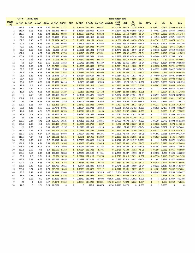
Depth
(ft)qc (tsf) fs (tsf) u (psi) Other qt (tsf) Rf(%) SBT Ic SBT ã (pcf) ó,v (tsf) u0 (tsf)
ó',vo
(tsf)Qt1
Fr
(%)Bq SBTn n Cn Ic Qtn
1 121.8 1.67 -0.19 1.57 121.798 1.3711 6 1.95618 125.7366 0.06287 0 0.0629 1936.3 1.3718 -1E-04 6 0.4631 3.6963 1.5969 425.2625
2 119.9 1.16 -0.31 1.72 119.896 0.9675 6 1.85954 123.0319 0.12438 0 0.1244 962.92 0.9685 -2E-04 6 0.453 2.6376 1.5635 298.562
3 116.5 1 -0.19 1.92 116.498 0.8584 6 1.83597 121.8758 0.18532 0 0.1853 627.62 0.8598 -1E-04 6 0.4618 2.2356 1.5805 245.7454
4 66.6 0.63 -0.29 2.12 66.5965 0.946 6 2.05491 117.1312 0.24389 0 0.2439 272.06 0.9495 -3E-04 6 0.543 2.2185 1.7871 139.1179
5 52.7 0.46 -0.38 2.26 52.6954 0.8729 5 2.11909 114.259 0.30102 0 0.301 174.06 0.878 -5E-04 6 0.5761 2.063 1.8675 102.1531
6 60.2 0.53 -0.48 2.47 60.1941 0.8805 5 2.07309 115.6199 0.35883 0 0.3588 166.75 0.8858 -6E-04 6 0.5743 1.8608 1.8598 105.2286
7 42.6 0.49 -0.57 2.68 42.593 1.1504 5 2.26264 114.2021 0.41593 0 0.4159 101.4 1.1618 -1E-03 5 0.6523 1.8388 2.056 73.29534
8 62.1 0.65 -0.57 2.86 62.093 1.0468 5 2.10531 117.1891 0.47452 0 0.4745 129.85 1.0549 -7E-04 6 0.6118 1.6334 1.9419 95.11835
9 102.8 1 -0.67 3.08 102.792 0.9728 6 1.91243 121.5705 0.53531 0 0.5353 191.02 0.9779 -5E-04 6 0.5573 1.4619 1.7908 141.2825
10 100.4 0.79 -0.58 3.25 100.393 0.7869 6 1.86382 119.7881 0.5952 0 0.5952 167.67 0.7916 -4E-04 6 0.5484 1.3709 1.7596 129.3021
11 77.2 0.52 -0.57 3.43 77.193 0.6736 6 1.91872 116.0872 0.65325 0 0.6533 117.17 0.6794 -5E-04 6 0.5757 1.32 1.8241 95.48661
12 58 0.67 -0.57 3.56 57.993 1.1553 5 2.15458 117.2442 0.71187 0 0.7119 80.466 1.1697 -7E-04 5 0.6724 1.3054 2.0703 70.66703
13 58.8 0.65 -0.51 3.7 58.7938 1.1056 5 2.13845 117.0559 0.7704 0 0.7704 75.316 1.1202 -6E-04 5 0.6758 1.2392 2.0721 67.95393
14 69.7 0.69 -0.48 3.85 69.6941 0.99 6 2.05054 117.9077 0.82935 0 0.8294 83.035 1.002 -5E-04 6 0.6522 1.1722 2.0027 76.28955
15 86.8 1.01 -0.48 3.99 86.7941 1.1637 6 2.01857 121.2307 0.88996 0 0.89 96.525 1.1757 -4E-04 6 0.6495 1.119 1.9875 90.84389
16 98.3 1.22 -0.48 4.14 98.2941 1.2412 6 1.99554 122.9164 0.95142 0 0.9514 102.31 1.2533 -4E-04 6 0.649 1.0714 1.9791 98.56679
17 97.7 1.15 -0.4 4.3 97.6951 1.1771 6 1.98248 122.4691 1.01266 0 1.0127 95.474 1.1895 -3E-04 6 0.652 1.029 1.9794 94.02646
18 20.6 0.75 -0.38 4.43 20.5954 3.6416 3 2.8158 115.5445 1.07043 0 1.0704 18.24 3.8413 -0.001 3 0.9873 0.9886 2.8523 18.24294
19 17.5 0.5 0.43 4.62 17.5053 2.8563 4 2.80659 112.1812 1.12652 0 1.1265 14.539 3.0527 0.0019 3 0.9963 0.9395 2.8688 14.54263
20 18.1 0.69 -0.07 4.75 18.0991 3.8123 3 2.87191 114.6193 1.18383 0 1.1838 14.289 4.0791 -3E-04 3 1 0.8938 2.9513 14.28863
21 15.2 0.78 -0.26 4.89 15.1968 5.1327 3 3.0125 115.0901 1.24138 0 1.2414 11.242 5.5892 -0.001 3 1 0.8524 3.1181 11.24192
22 111 2.58 -1.49 5.02 110.982 2.3247 5 2.14871 128.6925 1.30572 0 1.3057 83.997 2.3524 -1E-03 5 0.7511 0.8539 2.2028 88.50933
23 152.4 2.2 -4.77 5.15 152.342 1.4441 6 1.90365 128.2992 1.36987 0 1.3699 110.21 1.4572 -0.002 6 0.6622 0.8428 1.9611 120.2536
24 157 2.38 -0.19 5.33 156.998 1.516 6 1.91007 128.9481 1.43435 0 1.4344 108.46 1.5299 -9E-05 6 0.6711 0.8153 1.9771 119.8713
25 105.5 1.63 -0.4 5.5 105.495 1.5451 5 2.03712 125.2088 1.49695 0 1.497 69.473 1.5673 -3E-04 5 0.7311 0.776 2.1268 76.26748
26 60.8 1.33 -6.77 5.66 60.7171 2.1905 5 2.31594 122.3731 1.55814 0 1.5581 37.968 2.2482 -0.008 5 0.8535 0.7187 2.4398 40.18239
27 14.5 0.59 -6.84 5.72 14.4163 4.0926 3 2.96844 112.9188 1.6146 0 1.6146 7.9287 4.6088 -0.038 3 1 0.6553 3.187 7.92872
28 12.9 0.4 -6.51 5.82 12.8203 3.1201 3 2.93843 109.7888 1.66949 0 1.6695 6.6792 3.5872 -0.042 3 1 0.6338 3.1855 6.67918
29 23 1.33 -6.03 5.96 22.9262 5.8012 3 2.91361 119.9976 1.72949 0 1.7295 12.256 6.2746 -0.02 3 1 0.6118 3.1214 12.25605
30 135.6 2.24 -4.45 6.12 135.546 1.6526 6 1.98105 128.1461 1.79356 0 1.7936 74.573 1.6747 -0.002 5 0.7384 0.6773 2.1092 85.61158
31 103.5 2.06 -0.1 6.21 103.499 1.9904 5 2.12046 126.8753 1.857 0 1.857 54.734 2.0267 -7E-05 5 0.8038 0.6363 2.273 61.12048
32 122 2.68 -1.4 6.33 121.983 2.197 5 2.10296 129.2012 1.9216 0 1.9216 62.48 2.2322 -8E-04 5 0.8008 0.6202 2.257 70.36661
33 115.7 2.93 0.09 6.47 115.701 2.5324 5 2.16429 129.7248 1.98646 0 1.9865 57.245 2.5766 6E-05 5 0.8323 0.592 2.3318 63.62072
34 163.1 3.92 0.14 6.59 163.102 2.4034 5 2.05094 132.6922 2.05281 0 2.0528 78.453 2.434 6E-05 5 0.7882 0.5931 2.2077 90.27479
35 215.1 4.87 0.1 6.7 215.101 2.2641 6 1.9571 134.955 2.12029 0 2.1203 100.45 2.2866 3E-05 5 0.7527 0.5926 2.106 119.2885
36 30.9 1.56 0.14 6.7 30.9017 5.0483 3 2.77789 121.8929 2.18123 0 2.1812 13.167 5.4317 0.0004 3 1 0.4851 3.0572 13.16709
37 181.5 2.64 0.21 6.68 181.503 1.4545 6 1.85438 130.0604 2.24626 0 2.2463 79.802 1.4728 8E-05 5 0.7293 0.5775 2.0287 97.84089
38 228.3 3.43 -0.04 6.76 228.3 1.5024 6 1.80044 132.5354 2.31253 0 2.3125 97.723 1.5178 -1E-05 6 0.7091 0.5744 1.9675 122.679
39 169.2 3.59 -0.1 6.9 169.199 2.1218 5 1.99884 132.1383 2.3786 0 2.3786 70.134 2.152 -4E-05 5 0.7994 0.5233 2.1965 82.5059
40 108.1 3.12 -0.19 7.03 108.098 2.8863 5 2.22648 130.0188 2.44361 0 2.4436 43.237 2.953 -1E-04 4 0.9072 0.468 2.4695 46.72832
41 88.6 2.5 -2.94 7.13 88.564 2.8228 5 2.27711 127.9117 2.50756 0 2.5076 34.319 2.9051 -0.002 4 0.9396 0.4445 2.5472 36.15478
42 132.8 3.25 -0.29 7.25 132.796 2.4474 5 2.11388 130.8194 2.57297 0 2.573 50.612 2.4957 -2E-04 5 0.87 0.4616 2.3577 56.80998
43 107.5 3.5 -0.38 7.38 107.495 3.256 5 2.26781 130.8461 2.6384 0 2.6384 39.743 3.3379 -3E-04 4 0.9434 0.4224 2.5408 41.85406
44 166.8 3.28 -0.38 7.57 166.795 1.9665 6 1.9774 131.4426 2.70412 0 2.7041 60.682 1.9989 -2E-04 5 0.8232 0.4619 2.2183 71.63407
45 225.8 4.21 -0.48 7.78 225.794 1.8645 6 1.87704 134.0077 2.77112 0 2.7711 80.481 1.8877 -2E-04 5 0.781 0.4714 2.0992 99.36861
46 96.7 2.48 -0.48 7.96 96.6941 2.5648 5 2.22065 128.0671 2.83516 0.0312 2.804 33.474 2.6423 -7E-04 4 0.9465 0.3976 2.5284 35.26427
47 18.9 0.81 -0.59 8.07 18.8928 4.2874 3 2.88984 115.8972 2.8931 0.0624 2.8307 5.6522 5.0626 -0.007 3 1 0.3738 3.3301 5.65219
48 17 0.52 0.2 8.07 17.0025 3.0584 4 2.83452 112.3971 2.9493 0.0936 2.8557 4.9211 3.7002 -0.006 3 1 0.3705 3.3037 4.92108
49 24 1 0.58 8.17 24.0071 4.1654 3 2.80253 118.0233 3.00831 0.1248 2.8835 7.2824 4.7622 -0.004 3 1 0.367 3.2252 7.28236
50 17.7 0 1.04 8.29 17.7127 0 0 0 120.9 3.06876 0.156 2.9128 5.0275 0 -0.006 0 1 0.3633 0 0
CPT-6 In situ data Basic output data
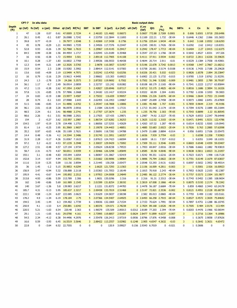
Depth
(ft)qc (tsf) fs (tsf) u (psi) Other qt (tsf) Rf(%) SBT Ic SBT ã (pcf) ó,v (tsf) u0 (tsf)
ó',vo
(tsf)Qt1
Fr
(%)Bq SBTn n Cn Ic Qtn
1 47 1.28 0.07 0.61 47.0009 2.7234 4 2.46183 121.4682 0.06073 0 0.0607 772.88 2.7269 0.0001 8 0.606 5.6501 1.9718 250.6496
2 26.1 0.45 -0.1 0.87 26.0988 1.7242 4 2.53759 112.3844 0.11693 0 0.1169 222.21 1.732 -3E-04 5 0.6446 4.1362 2.066 101.5653
3 39.8 0.77 -0.19 1 39.7977 1.9348 5 2.42069 117.3438 0.1756 0 0.1756 225.64 1.9434 -4E-04 5 0.642 3.168 2.0552 118.6293
4 45 0.78 -0.29 1.21 44.9965 1.7335 5 2.34926 117.7376 0.23447 0 0.2345 190.91 1.7426 -5E-04 5 0.6392 2.62 2.0412 110.8351
5 52.8 0.93 -0.26 1.39 52.7968 1.7615 5 2.29967 119.4145 0.29417 0 0.2942 178.47 1.7713 -4E-04 5 0.6404 2.27 2.0415 112.6375
6 84.5 0.99 -0.38 1.56 84.4954 1.1717 6 2.02945 121.0189 0.35468 0 0.3547 237.23 1.1766 -3E-04 6 0.5642 1.8527 1.8331 147.326
7 16 0.56 -0.38 1.72 15.9954 3.501 3 2.89118 112.7905 0.41108 0 0.4111 37.911 3.5934 -0.002 4 0.8722 2.2811 2.6326 33.59635
8 10.1 0.28 -1.37 1.83 10.0832 2.7769 3 2.99536 106.5933 0.46438 0 0.4644 20.714 2.911 -0.01 4 0.9229 2.1384 2.7558 19.43901
9 12.3 0.44 0.21 1.89 12.3026 3.5765 3 2.9878 110.3857 0.51957 0 0.5196 22.678 3.7342 0.0013 4 0.9368 1.947 2.7867 21.68212
10 15.9 0.54 2.3 2.08 15.9282 3.3902 3 2.88414 112.5141 0.57583 0 0.5758 26.661 3.5174 0.0108 4 0.9136 1.7435 2.7188 25.29628
11 13.6 0.65 -4.09 2.19 13.5499 4.7971 3 3.03242 113.4763 0.63256 0 0.6326 20.421 5.032 -0.023 3 0.9826 1.6578 2.894 20.23847
12 16 0.79 -3.16 2.29 15.9613 4.9495 3 2.98602 115.303 0.69022 0 0.6902 22.125 5.1732 -0.015 3 0.9785 1.519 2.8762 21.92291
13 24.3 1.3 -2.78 2.39 24.266 5.3573 3 2.87202 119.9692 0.7502 0 0.7502 31.346 5.5282 -0.009 3 0.9481 1.3855 2.789 30.79187
14 56.1 1.17 -0.7 2.49 56.0914 2.0859 5 2.32737 121.242 0.81082 0 0.8108 68.179 2.1165 -9E-04 5 0.7541 1.2223 2.2717 63.85844
15 47.2 1.15 -0.38 2.62 47.1954 2.4367 5 2.42827 120.6946 0.87117 0 0.8712 53.175 2.4825 -6E-04 5 0.8016 1.1686 2.3894 51.16326
16 57.8 1.31 -0.85 2.76 57.7896 2.2668 5 2.34182 122.1417 0.93224 0 0.9322 60.99 2.304 -0.001 5 0.7782 1.1036 2.3203 59.3003
17 24 0.83 -0.19 2.88 23.9977 3.4587 4 2.75032 116.659 0.99057 0 0.9906 23.226 3.6076 -6E-04 4 0.9466 1.0644 2.7553 23.14449
18 28 0.74 -0.1 3.03 27.9988 2.643 4 2.62455 116.1953 1.04867 0 1.0487 25.699 2.7458 -3E-04 4 0.9073 1.0082 2.6451 25.67809
19 51.5 0.86 -0.85 3.14 51.4896 1.6702 5 2.29347 118.7808 1.10806 0 1.1081 45.468 1.707 -0.001 5 0.7859 0.9644 2.319 45.9196
20 96.1 2.01 -0.18 3.28 96.0978 2.0916 5 2.1584 126.5145 1.17131 0 1.1713 81.043 2.1174 -1E-04 5 0.7394 0.9276 2.1889 83.21844
21 98.5 2.24 -0.1 3.41 98.4988 2.2741 5 2.17707 127.3674 1.235 0 1.235 78.756 2.303 -7E-05 5 0.7543 0.8899 2.22 81.80545
22 98.6 2.26 -0.1 3.51 98.5988 2.2921 5 2.17925 127.435 1.29871 0 1.2987 74.92 2.3227 -7E-05 5 0.7629 0.8553 2.2347 78.64948
23 154 2 -0.27 3.62 153.997 1.2987 6 1.86724 127.6282 1.36253 0 1.3625 112.02 1.3103 -1E-04 6 0.6471 0.8491 1.9231 122.4786
24 154.5 1.97 -0.19 3.78 154.498 1.2751 6 1.86056 127.5255 1.42629 0 1.4263 107.32 1.287 -9E-05 6 0.6514 0.8232 1.9265 119.0945
25 81.4 1.6 -0.25 3.95 81.3969 1.9657 5 2.19078 124.4403 1.48851 0 1.4885 53.683 2.0023 -2E-04 5 0.7926 0.763 2.2885 57.62098
26 35.2 0.97 -6.63 4.06 35.1189 2.7621 4 2.56091 118.7282 1.54788 0 1.5479 21.688 2.8894 -0.014 4 0.956 0.6951 2.7106 22.05475
27 14.4 0.48 -5.36 4.2 14.3344 3.3486 3 2.91745 111.3951 1.60357 0 1.6036 7.939 3.7704 -0.03 3 1 0.6598 3.1358 7.93903
28 31.9 2.28 -5.17 4.36 31.8367 7.1615 3 2.87613 124.7423 1.66594 0 1.6659 18.11 7.557 -0.012 3 1 0.6351 3.049 18.11031
29 97.2 3.2 -6.22 4.53 97.1239 3.2948 5 2.30037 129.9429 1.73092 0 1.7309 55.111 3.3546 -0.005 4 0.8603 0.6548 2.4359 59.03407
30 127.2 2.51 -0.48 4.57 127.194 1.9734 5 2.05624 128.8238 1.79533 0 1.7953 69.847 2.0016 -3E-04 5 0.7686 0.6661 2.1882 78.93819
31 58.7 2.31 -0.73 4.67 58.6911 3.9359 4 2.50466 126.3298 1.85849 0 1.8585 30.58 4.0646 -9E-04 4 0.9638 0.5811 2.6923 31.21057
32 193.1 3.1 -0.48 4.83 193.094 1.6054 6 1.86907 131.3867 1.92419 0 1.9242 99.351 1.6216 -2E-04 6 0.7023 0.6571 1.998 118.7128
33 152.8 3.14 -0.57 4.94 152.793 2.0551 5 2.01662 130.9096 1.98964 0 1.9896 75.794 2.0822 -3E-04 5 0.7701 0.6149 2.1679 87.63837
34 111.6 3.19 -3.25 5.09 111.56 2.8594 5 2.21445 130.258 2.05477 0 2.0548 53.293 2.9131 -0.002 5 0.8597 0.5652 2.3952 58.49314
35 36 1.45 -1.2 5.15 35.9853 4.0294 4 2.6625 121.7293 2.11563 0 2.1156 16.009 4.2811 -0.003 3 1 0.5001 2.926 16.00923
36 156.9 3.47 -0.94 5.32 156.888 2.2118 5 2.03363 131.7053 2.18149 0 2.1815 70.918 2.243 -4E-04 5 0.7953 0.5625 2.2103 82.2387
37 195.9 4.41 -0.67 5.44 195.892 2.2512 6 1.97953 134.0008 2.24849 0 2.2485 86.122 2.2774 -3E-04 5 0.7757 0.5573 2.1504 101.9877
38 213.8 4.93 -0.86 5.59 213.789 2.306 6 1.9651 135.0296 2.316 0 2.316 91.31 2.3313 -3E-04 5 0.7743 0.5452 2.1385 108.9654
39 162 3.49 -0.86 5.69 161.989 2.1545 5 2.01599 131.8254 2.38192 0 2.3819 67.008 2.1866 -4E-04 5 0.8075 0.5193 2.2174 78.3342
40 140 3.67 -1.36 5.8 139.983 2.6217 5 2.1221 131.8372 2.44783 0 2.4478 56.187 2.6684 -7E-04 5 0.859 0.4865 2.3443 63.24178
41 185.7 4.31 -5.13 5.95 185.637 2.3217 5 2.00438 133.7019 2.51468 0 2.5147 72.821 2.3536 -0.002 5 0.8121 0.4951 2.2128 85.68739
42 222.1 4.58 -1.24 6.07 222.085 2.0623 6 1.91629 134.5837 2.58198 0 2.582 85.013 2.0865 -4E-04 5 0.7793 0.499 2.1182 103.5161
43 178.2 4.9 -1.34 6.19 178.184 2.75 5 2.07366 134.5407 2.64925 0 2.6493 66.258 2.7915 -6E-04 5 0.8527 0.4572 2.3029 75.84642
44 194.5 3.45 -1.44 6.3 194.482 1.7739 6 1.90036 132.1869 2.71534 0 2.7153 70.624 1.7991 -5E-04 5 0.7897 0.4751 2.1288 86.10745
45 250.9 4.1 -1.53 6.4 250.881 1.6342 6 1.80376 134.071 2.78238 0 2.7824 89.168 1.6526 -4E-04 5 0.7505 0.484 2.0176 113.494
46 220.5 5.21 -1.63 6.54 220.48 2.363 6 1.96579 135.509 2.85013 0.0312 2.8189 77.203 2.394 -7E-04 5 0.8203 0.4476 2.1966 92.06544
47 29.1 1.21 -1.65 6.61 29.0798 4.161 4 2.73995 119.8857 2.91007 0.0624 2.8477 9.1899 4.6237 -0.007 3 1 0.3716 3.1364 9.18986
48 54.5 2.34 -4.12 6.38 54.4496 4.2976 4 2.55478 126.2413 2.97319 0.0936 2.8796 17.876 4.5458 -0.008 3 1 0.3675 2.9058 17.87626
49 16.6 0.59 -3.93 6.45 16.5519 3.5646 3 2.88422 113.2557 3.02982 0.1248 2.905 4.6547 4.3632 -0.03 3 1 0.3642 3.3631 4.65472
50 22.8 0 -3.64 6.52 22.7555 0 0 0 120.9 3.09027 0.156 2.9343 6.7019 0 -0.021 0 1 0.3606 0 0
CPT-7 In situ data Basic output data
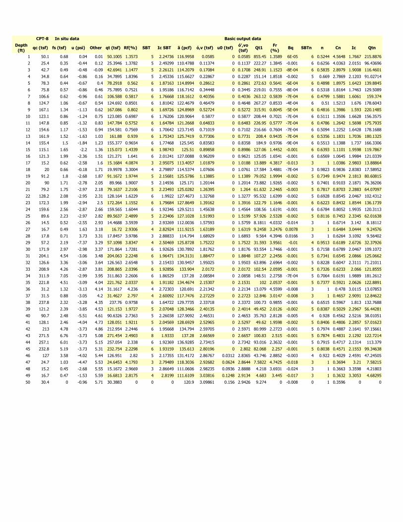
Depth
(ft)qc (tsf) fs (tsf) u (psi) Other qt (tsf) Rf(%) SBT Ic SBT ã (pcf) ó,v (tsf) u0 (tsf)
ó',vo
(tsf)Qt1
Fr
(%)Bq SBTn n Cn Ic Qtn
1 50.1 0.68 0.04 0.01 50.1005 1.3573 5 2.24736 116.9958 0.0585 0 0.0585 855.45 1.3589 6E-05 6 0.5244 4.5648 1.7667 215.8876
2 25.4 0.35 -0.44 0.12 25.3946 1.3782 5 2.49299 110.4788 0.11374 0 0.1137 222.27 1.3845 -0.001 6 0.6256 4.0363 2.0151 96.43696
3 42.7 0.49 -0.48 -0.09 42.6941 1.1477 5 2.26121 114.2079 0.17084 0 0.1708 248.91 1.1523 -8E-04 6 0.5835 2.8979 1.9008 116.4601
4 34.8 0.64 -0.86 0.16 34.7895 1.8396 5 2.45336 115.6627 0.22867 0 0.2287 151.14 1.8518 -0.002 5 0.669 2.7869 2.1203 91.02714
5 78.3 0.44 -0.67 0.4 78.2918 0.562 6 1.87163 114.8994 0.28612 0 0.2861 272.63 0.5641 -6E-04 6 0.4898 1.8975 1.6423 139.8845
6 75.8 0.57 -0.86 0.46 75.7895 0.7521 6 1.95186 116.7142 0.34448 0 0.3445 219.01 0.7555 -8E-04 6 0.5318 1.8164 1.7463 129.5089
7 106.6 0.62 -0.96 0.61 106.588 0.5817 6 1.76668 118.1612 0.40356 0 0.4036 263.12 0.5839 -7E-04 6 0.4799 1.5881 1.6061 159.374
8 124.7 1.06 -0.67 0.54 124.692 0.8501 6 1.81042 122.4679 0.46479 0 0.4648 267.27 0.8533 -4E-04 6 0.51 1.5213 1.676 178.6043
9 167.1 1.34 -1.13 0.62 167.086 0.802 6 1.69726 124.8969 0.52724 0 0.5272 315.91 0.8045 -5E-04 6 0.4816 1.3986 1.593 220.1485
10 123.1 0.86 -1.24 0.75 123.085 0.6987 6 1.76206 120.9064 0.5877 0 0.5877 208.44 0.7021 -7E-04 6 0.5111 1.3506 1.6628 156.3575
11 147.8 0.85 -1.32 0.83 147.784 0.5752 6 1.64784 121.2668 0.64833 0 0.6483 226.95 0.5777 -7E-04 6 0.4786 1.2642 1.5698 175.7935
12 154.6 1.17 -1.53 0.94 154.581 0.7569 6 1.70642 123.7145 0.71019 0 0.7102 216.66 0.7604 -7E-04 6 0.5094 1.2252 1.6428 178.1688
13 161.9 1.52 -1.63 1.03 161.88 0.939 6 1.75343 125.7419 0.77306 0 0.7731 208.4 0.9435 -7E-04 6 0.5356 1.1831 1.7036 180.1325
14 155.4 1.5 -1.84 1.23 155.377 0.9654 6 1.77468 125.545 0.83583 0 0.8358 184.9 0.9706 -9E-04 6 0.5513 1.1388 1.737 166.3306
15 115.1 1.65 -2.2 1.36 115.073 1.4339 6 1.98743 125.51 0.89858 0 0.8986 127.06 1.4452 -0.001 6 0.6393 1.1101 1.9598 119.7867
16 121.3 1.99 -2.36 1.51 121.271 1.641 6 2.01241 127.0088 0.96209 0 0.9621 125.05 1.6541 -0.001 6 0.6569 1.0645 1.9984 121.0339
17 15.2 0.62 -2.58 1.6 15.1684 4.0874 3 2.95075 113.4057 1.01879 0 1.0188 13.889 4.3817 -0.013 3 1 1.0386 2.9803 13.88864
18 20 0.66 -0.18 1.71 19.9978 3.3004 4 2.79897 114.5374 1.07606 0 1.0761 17.584 3.4881 -7E-04 3 0.9823 0.9836 2.8383 17.58952
19 91.2 1.8 -2.68 1.87 91.1672 1.9744 5 2.15681 125.5786 1.13885 0 1.1389 79.052 1.9994 -0.002 5 0.7349 0.9474 2.1813 80.60815
20 90 1.71 -2.78 2.05 89.966 1.9007 5 2.14936 125.171 1.20144 0 1.2014 73.882 1.9265 -0.002 5 0.7401 0.9103 2.1871 76.36206
21 79.2 1.75 -2.97 2.18 79.1637 2.2106 5 2.23493 125.0282 1.26395 0 1.264 61.632 2.2465 -0.003 5 0.7817 0.8703 2.2883 64.07097
22 128.2 2.08 -2.95 2.31 128.164 1.6229 6 1.9922 127.4673 1.32768 0 1.3277 95.532 1.6399 -0.002 5 0.6928 0.8545 2.0467 102.4312
23 172.3 1.99 -2.94 2.5 172.264 1.1552 6 1.79684 127.8649 1.39162 0 1.3916 122.79 1.1646 -0.001 6 0.6223 0.8432 1.8544 136.1739
24 159.6 2.56 -2.87 2.66 159.565 1.6044 6 1.92346 129.5211 1.45638 0 1.4564 108.56 1.6191 -0.001 6 0.6784 0.8052 1.9935 120.3113
25 89.6 2.23 -2.97 2.82 89.5637 2.4899 5 2.23406 127.1028 1.51993 0 1.5199 57.926 2.5328 -0.002 5 0.8116 0.7453 2.3345 62.01638
26 14.5 0.52 -2.55 2.93 14.4688 3.5939 3 2.93269 112.0036 1.57593 0 1.5759 8.1811 4.0332 -0.014 3 1 0.6714 3.142 8.18112
27 16.7 0.49 1.63 3.18 16.72 2.9306 4 2.82924 111.9215 1.63189 0 1.6319 9.2458 3.2476 0.0078 3 1 0.6484 3.0444 9.24576
28 17.8 0.71 3.73 3.31 17.8457 3.9786 3 2.88833 114.794 1.68929 0 1.6893 9.564 4.3946 0.0166 3 1 0.6264 3.1092 9.56402
29 57.2 2.19 -7.37 3.29 57.1098 3.8347 4 2.50469 125.8728 1.75222 0 1.7522 31.593 3.9561 -0.01 4 0.9513 0.6189 2.6726 32.37926
30 171.9 2.97 -2.98 3.37 171.864 1.7281 6 1.92626 130.7892 1.81762 0 1.8176 93.554 1.7466 -0.001 5 0.7158 0.6789 2.0467 109.1072
31 204.1 4.54 -3.06 3.48 204.063 2.2248 6 1.96471 134.3131 1.88477 0 1.8848 107.27 2.2456 -0.001 5 0.7341 0.6545 2.0866 125.0662
32 126.6 3.36 -3.06 3.64 126.563 2.6548 5 2.15433 130.9457 1.95025 0 1.9503 63.896 2.6964 -0.002 5 0.8228 0.6047 2.3111 71.21011
33 208.9 4.26 -2.87 3.81 208.865 2.0396 6 1.92856 133.904 2.0172 0 2.0172 102.54 2.0595 -0.001 5 0.7326 0.6233 2.066 121.8555
34 311.9 7.05 -2.99 3.95 311.863 2.2606 6 1.86529 137.28 2.08584 0 2.0858 148.51 2.2758 -7E-04 5 0.7064 0.6191 1.9889 181.2612
35 221.8 4.51 -3.09 4.04 221.762 2.0337 6 1.91182 134.4674 2.15307 0 2.1531 102 2.0537 -0.001 5 0.7377 0.5921 2.0626 122.8891
36 31.2 1.32 -3.13 4.14 31.1617 4.236 4 2.72303 120.691 2.21342 0 2.2134 13.079 4.5599 -0.008 3 1 0.478 3.0115 13.07853
37 31.5 0.88 -3.05 4.2 31.4627 2.797 4 2.60092 117.7476 2.27229 0 2.2723 12.846 3.0147 -0.008 3 1 0.4657 2.9091 12.84622
38 237.8 2.32 -3.28 4.35 237.76 0.9758 6 1.64722 129.7735 2.33718 0 2.3372 100.73 0.9855 -0.001 6 0.6515 0.5967 1.813 132.7688
39 121.2 2.39 -3.85 4.53 121.153 1.9727 5 2.07048 128.3466 2.40135 0 2.4014 49.452 2.0126 -0.002 5 0.8387 0.5029 2.2967 56.44281
40 90.7 2.48 -5.51 4.61 90.6326 2.7363 5 2.26038 127.9092 2.46531 0 2.4653 35.763 2.8128 -0.005 4 0.928 0.4562 2.5216 38.01051
41 128.1 2.46 -4.04 4.73 128.051 1.9211 5 2.04569 128.6929 2.52965 0 2.5297 49.62 1.9598 -0.002 5 0.8406 0.4806 2.2857 57.01623
42 213 4.78 -3.73 4.86 212.954 2.2446 6 1.95668 134.794 2.59705 0 2.5971 80.999 2.2723 -0.001 5 0.7974 0.4887 2.1641 97.15661
43 271.5 6.76 -3.73 5.08 271.454 2.4903 8 1.9333 137.28 2.66569 0 2.6657 100.83 2.515 -0.001 5 0.7874 0.4831 2.1292 122.7214
44 257.1 6.01 -3.73 5.15 257.054 2.338 6 1.92369 136.9285 2.73415 0 2.7342 93.016 2.3632 -0.001 5 0.7915 0.4717 2.1314 113.379
45 232.8 5.19 -3.73 5.31 232.754 2.2298 6 1.93159 135.613 2.80196 0 2.802 82.068 2.257 -0.001 5 0.8038 0.4571 2.1553 99.34638
46 127 3.58 -4.02 5.44 126.951 2.82 5 2.17355 131.4172 2.86767 0.0312 2.8365 43.746 2.8852 -0.003 4 0.922 0.4029 2.4591 47.24505
47 24.7 1.03 -4.47 5.53 24.6453 4.1793 3 2.79489 118.3036 2.92682 0.0624 2.8644 7.5822 4.7425 -0.018 3 1 0.3694 3.21 7.58215
48 15.2 0.45 -2.68 5.55 15.1672 2.9669 3 2.86649 111.0606 2.98235 0.0936 2.8888 4.218 3.6931 -0.024 3 1 0.3663 3.3598 4.21803
49 16.7 0.47 -1.53 5.59 16.6813 2.8175 4 2.8199 111.6109 3.03816 0.1248 2.9134 4.683 3.445 -0.017 3 1 0.3632 3.3053 4.68295
50 30.4 0 -0.96 5.71 30.3883 0 0 0 120.9 3.09861 0.156 2.9426 9.274 0 -0.008 0 1 0.3596 0 0
CPT-8 In situ data Basic output data
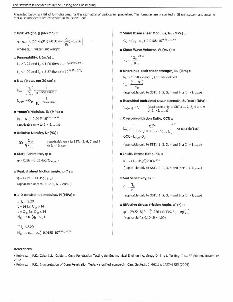
APPENDIX B LOGS OF EXPLORATORY BORINGS
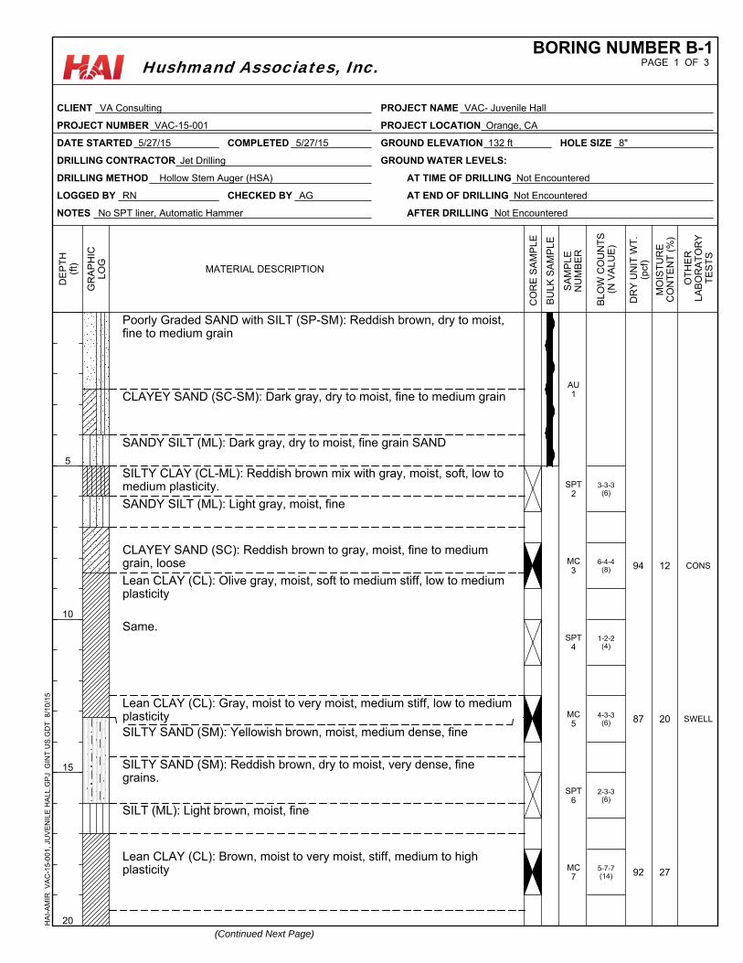
3-3-3(6)
6-4-4(8)
1-2-2(4)
4-3-3(6)
2-3-3(6)
5-7-7(14)
Poorly Graded SAND with SILT (SP-SM): Reddish brown, dry to moist,fine to medium grain
CLAYEY SAND (SC-SM): Dark gray, dry to moist, fine to medium grain
SANDY SILT (ML): Dark gray, dry to moist, fine grain SAND
SILTY CLAY (CL-ML): Reddish brown mix with gray, moist, soft, low tomedium plasticity.
SANDY SILT (ML): Light gray, moist, fine
CLAYEY SAND (SC): Reddish brown to gray, moist, fine to mediumgrain, loose
Lean CLAY (CL): Olive gray, moist, soft to medium stiff, low to mediumplasticity
Same.
Lean CLAY (CL): Gray, moist to very moist, medium stiff, low to mediumplasticitySILTY SAND (SM): Yellowish brown, moist, medium dense, fine
SILTY SAND (SM): Reddish brown, dry to moist, very dense, finegrains.
SILT (ML): Light brown, moist, fine
Lean CLAY (CL): Brown, moist to very moist, stiff, medium to highplasticity
94
87
92
12
20
27
CONS
SWELL
AU1
SPT2
MC3
SPT4
MC5
SPT6
MC7
NOTES No SPT liner, Automatic Hammer
GROUND ELEVATION 132 ft
LOGGED BY RN
DATE STARTED 5/27/15
DRILLING METHOD Hollow Stem Auger (HSA) AT TIME OF DRILLING Not Encountered
AT END OF DRILLING Not Encountered
AFTER DRILLING Not Encountered
HOLE SIZE 8"
DRILLING CONTRACTOR Jet Drilling GROUND WATER LEVELS:
CHECKED BY AG
COMPLETED 5/27/15
MO
IST
UR
EC
ON
TE
NT
(%
)
BU
LK
SA
MP
LE
SA
MP
LE
NU
MB
ER
(Continued Next Page)
MATERIAL DESCRIPTION
OT
HE
RLA
BO
RA
TO
RY
TE
ST
S
5
10
15
20
DE
PT
H(f
t)
GR
AP
HIC
LO
G
DR
Y U
NIT
WT
.(p
cf)
CO
RE
SA
MP
LE
BL
OW
CO
UN
TS
(N V
AL
UE
)
PAGE 1 OF 3BORING NUMBER B-1
CLIENT VA Consulting
PROJECT NUMBER VAC-15-001
PROJECT NAME VAC- Juvenile Hall
PROJECT LOCATION Orange, CA
HA
I-A
MIR
V
AC
-15-
001,
JU
VE
NIL
E H
ALL
.GP
J G
INT
US
.GD
T
8/10
/15
Hushmand Associates, Inc.
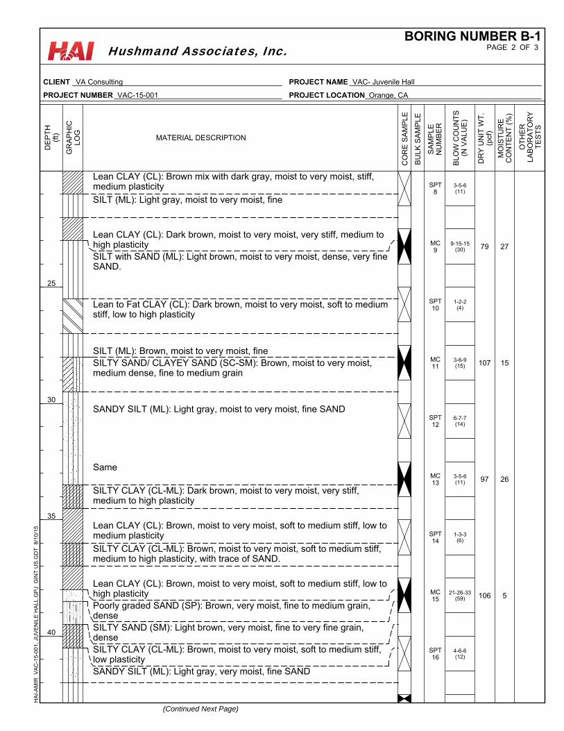
3-5-6(11)
9-15-15(30)
1-2-2(4)
3-6-9(15)
6-7-7(14)
3-5-6(11)
1-3-3(6)
21-26-33(59)
4-6-6(12)
Lean CLAY (CL): Brown mix with dark gray, moist to very moist, stiff,medium plasticity
SILT (ML): Light gray, moist to very moist, fine
Lean CLAY (CL): Dark brown, moist to very moist, very stiff, medium tohigh plasticitySILT with SAND (ML): Light brown, moist to very moist, dense, very fineSAND.
Lean to Fat CLAY (CL): Dark brown, moist to very moist, soft to mediumstiff, low to high plasticity
SILT (ML): Brown, moist to very moist, fineSILTY SAND/ CLAYEY SAND (SC-SM): Brown, moist to very moist,medium dense, fine to medium grain
SANDY SILT (ML): Light gray, moist to very moist, fine SAND
Same
SILTY CLAY (CL-ML): Dark brown, moist to very moist, very stiff,medium to high plasticity
Lean CLAY (CL): Brown, moist to very moist, soft to medium stiff, low tomedium plasticity
SILTY CLAY (CL-ML): Brown, moist to very moist, soft to medium stiff,medium to high plasticity, with trace of SAND.
Lean CLAY (CL): Brown, moist to very moist, soft to medium stiff, low tohigh plasticityPoorly graded SAND (SP): Brown, very moist, fine to medium grain,denseSILTY SAND (SM): Light brown, very moist, fine to very fine grain,denseSILTY CLAY (CL-ML): Brown, moist to very moist, soft to medium stiff,low plasticitySANDY SILT (ML): Light gray, very moist, fine SAND
79
107
97
106
27
15
26
5
SPT8
MC9
SPT10
MC11
SPT12
MC13
SPT14
MC15
SPT16
MO
IST
UR
EC
ON
TE
NT
(%
)
BU
LK
SA
MP
LE
SA
MP
LE
NU
MB
ER
(Continued Next Page)
MATERIAL DESCRIPTION
OT
HE
RLA
BO
RA
TO
RY
TE
ST
S
25
30
35
40
DE
PT
H(f
t)
GR
AP
HIC
LO
G
DR
Y U
NIT
WT
.(p
cf)
CO
RE
SA
MP
LE
BL
OW
CO
UN
TS
(N V
AL
UE
)
PAGE 2 OF 3BORING NUMBER B-1
CLIENT VA Consulting
PROJECT NUMBER VAC-15-001
PROJECT NAME VAC- Juvenile Hall
PROJECT LOCATION Orange, CA
HA
I-A
MIR
V
AC
-15-
001,
JU
VE
NIL
E H
ALL
.GP
J G
INT
US
.GD
T
8/10
/15
Hushmand Associates, Inc.
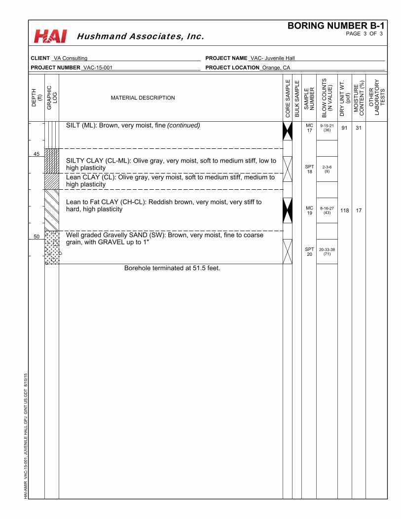
9-15-21(36)
2-3-6(9)
8-16-27(43)
20-33-38(71)
SILT (ML): Brown, very moist, fine (continued)
SILTY CLAY (CL-ML): Olive gray, very moist, soft to medium stiff, low tohigh plasticity
Lean CLAY (CL): Olive gray, very moist, soft to medium stiff, medium tohigh plasticity
Lean to Fat CLAY (CH-CL): Reddish brown, very moist, very stiff tohard, high plasticity
Well graded Gravelly SAND (SW): Brown, very moist, fine to coarsegrain, with GRAVEL up to 1"
Borehole terminated at 51.5 feet.
91
118
31
17
MC17
SPT18
MC19
SPT20
MO
IST
UR
EC
ON
TE
NT
(%
)
BU
LK
SA
MP
LE
SA
MP
LE
NU
MB
ER
MATERIAL DESCRIPTION
OT
HE
RLA
BO
RA
TO
RY
TE
ST
S
45
50
DE
PT
H(f
t)
GR
AP
HIC
LO
G
DR
Y U
NIT
WT
.(p
cf)
CO
RE
SA
MP
LE
BL
OW
CO
UN
TS
(N V
AL
UE
)
PAGE 3 OF 3BORING NUMBER B-1
CLIENT VA Consulting
PROJECT NUMBER VAC-15-001
PROJECT NAME VAC- Juvenile Hall
PROJECT LOCATION Orange, CA
HA
I-A
MIR
V
AC
-15-
001,
JU
VE
NIL
E H
ALL
.GP
J G
INT
US
.GD
T
8/10
/15
Hushmand Associates, Inc.
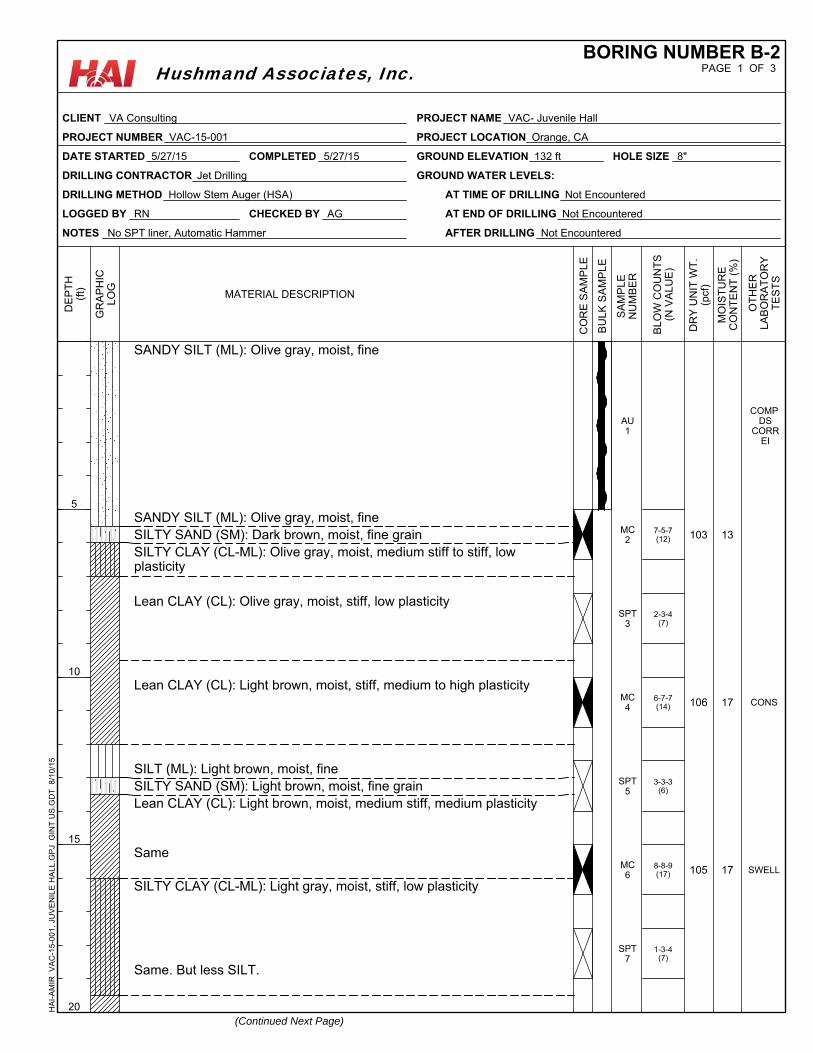
7-5-7(12)
2-3-4(7)
6-7-7(14)
3-3-3(6)
8-8-9(17)
1-3-4(7)
SANDY SILT (ML): Olive gray, moist, fine
SANDY SILT (ML): Olive gray, moist, fineSILTY SAND (SM): Dark brown, moist, fine grainSILTY CLAY (CL-ML): Olive gray, moist, medium stiff to stiff, lowplasticity
Lean CLAY (CL): Olive gray, moist, stiff, low plasticity
Lean CLAY (CL): Light brown, moist, stiff, medium to high plasticity
SILT (ML): Light brown, moist, fineSILTY SAND (SM): Light brown, moist, fine grainLean CLAY (CL): Light brown, moist, medium stiff, medium plasticity
Same
SILTY CLAY (CL-ML): Light gray, moist, stiff, low plasticity
Same. But less SILT.
103
106
105
13
17
17
COMP DS
CORR EI
CONS
SWELL
AU1
MC2
SPT3
MC4
SPT5
MC6
SPT7
NOTES No SPT liner, Automatic Hammer
GROUND ELEVATION 132 ft
LOGGED BY RN
DATE STARTED 5/27/15
DRILLING METHOD Hollow Stem Auger (HSA) AT TIME OF DRILLING Not Encountered
AT END OF DRILLING Not Encountered
AFTER DRILLING Not Encountered
HOLE SIZE 8"
DRILLING CONTRACTOR Jet Drilling GROUND WATER LEVELS:
CHECKED BY AG
COMPLETED 5/27/15
MO
IST
UR
EC
ON
TE
NT
(%
)
BU
LK
SA
MP
LE
SA
MP
LE
NU
MB
ER
(Continued Next Page)
MATERIAL DESCRIPTION
OT
HE
RLA
BO
RA
TO
RY
TE
ST
S
5
10
15
20
DE
PT
H(f
t)
GR
AP
HIC
LO
G
DR
Y U
NIT
WT
.(p
cf)
CO
RE
SA
MP
LE
BL
OW
CO
UN
TS
(N V
AL
UE
)
PAGE 1 OF 3BORING NUMBER B-2
CLIENT VA Consulting
PROJECT NUMBER VAC-15-001
PROJECT NAME VAC- Juvenile Hall
PROJECT LOCATION Orange, CA
HA
I-A
MIR
V
AC
-15-
001,
JU
VE
NIL
E H
ALL
.GP
J G
INT
US
.GD
T
8/10
/15
Hushmand Associates, Inc.
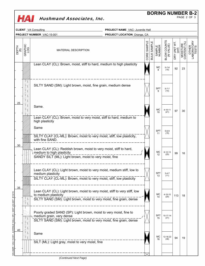
5-7-8(15)
5-7-7(14)
4-10-11(21)
5-6-9(15)
6-12-13(25)
3-4-7(11)
4-10-10(20)
10-17-14(31)
12-16-22(38)
Lean CLAY (CL): Brown, moist, stiff to hard, medium to high plasticity
SILTY SAND (SM): Light brown, moist, fine grain, medium dense
Same.
Lean CLAY (CL): Brown, moist to very moist, stiff to hard, medium tohigh plasticity
Same
SILTY CLAY (CL-ML): Brown, moist to very moist, stiff, low plasticity,with fine SAND.
Lean CLAY (CL): Reddish brown, moist to very moist, stiff to hard,medium to high plasticitySANDY SILT (ML): Light brown, moist to very moist, fine
Lean CLAY (CL): Light brown, moist to very moist, medium stiff, low tomedium plasticity
SILTY CLAY (CL-ML): Brown, moist to very moist, stiff, low plasticity
Lean CLAY (CL): Light brown, moist to very moist, stiff to very stiff, lowto medium plasticitySILTY SAND (SM): Light brown, moist to very moist, fine grain, dense
Poorly graded SAND (SP): Light brown, moist to very moist, fine tomedium grain, very denseSILTY SAND (SM): Light brown, moist to very moist, fine grain, dense
Same
SILT (ML): Light gray, moist to very moist, fine
92
97
99
113
94
23
30
16
18
19
MC8
SPT9
MC10
SPT11
MC12
SPT13
MC14
SPT15
MC16
MO
IST
UR
EC
ON
TE
NT
(%
)
BU
LK
SA
MP
LE
SA
MP
LE
NU
MB
ER
(Continued Next Page)
MATERIAL DESCRIPTION
OT
HE
RLA
BO
RA
TO
RY
TE
ST
S
25
30
35
40
DE
PT
H(f
t)
GR
AP
HIC
LO
G
DR
Y U
NIT
WT
.(p
cf)
CO
RE
SA
MP
LE
BL
OW
CO
UN
TS
(N V
AL
UE
)
PAGE 2 OF 3BORING NUMBER B-2
CLIENT VA Consulting
PROJECT NUMBER VAC-15-001
PROJECT NAME VAC- Juvenile Hall
PROJECT LOCATION Orange, CA
HA
I-A
MIR
V
AC
-15-
001,
JU
VE
NIL
E H
ALL
.GP
J G
INT
US
.GD
T
8/10
/15
Hushmand Associates, Inc.
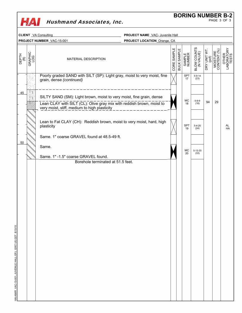
5-9-14(23)
5-9-9(18)
5-4-20(24)
5-13-20(33)
Poorly graded SAND with SILT (SP): Light gray, moist to very moist, finegrain, dense (continued)
SILTY SAND (SM): Light brown, moist to very moist, fine grain, dense
Lean CLAY with SILT (CL): Olive gray mix with reddish brown, moist tovery moist, stiff, medium to high plasticity
Lean to Fat CLAY (CH): Reddish brown, moist to very moist, hard, highplasticity
Same. 1" coarse GRAVEL found at 48.5-49 ft.
Same.
Same. 1" -1.5" coarse GRAVEL found. Borehole terminated at 51.5 feet.
94 29
AL HA
SPT17
MC18
SPT19
MC20
MO
IST
UR
EC
ON
TE
NT
(%
)
BU
LK
SA
MP
LE
SA
MP
LE
NU
MB
ER
MATERIAL DESCRIPTION
OT
HE
RLA
BO
RA
TO
RY
TE
ST
S
45
50
DE
PT
H(f
t)
GR
AP
HIC
LO
G
DR
Y U
NIT
WT
.(p
cf)
CO
RE
SA
MP
LE
BL
OW
CO
UN
TS
(N V
AL
UE
)
PAGE 3 OF 3BORING NUMBER B-2
CLIENT VA Consulting
PROJECT NUMBER VAC-15-001
PROJECT NAME VAC- Juvenile Hall
PROJECT LOCATION Orange, CA
HA
I-A
MIR
V
AC
-15-
001,
JU
VE
NIL
E H
ALL
.GP
J G
INT
US
.GD
T
8/10
/15
Hushmand Associates, Inc.
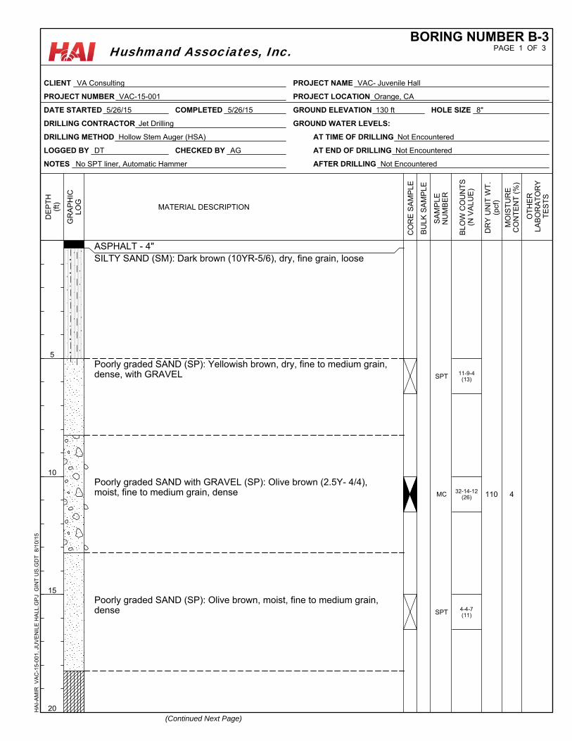
11-9-4(13)
32-14-12(26)
4-4-7(11)
ASPHALT - 4"SILTY SAND (SM): Dark brown (10YR-5/6), dry, fine grain, loose
Poorly graded SAND (SP): Yellowish brown, dry, fine to medium grain,dense, with GRAVEL
Poorly graded SAND with GRAVEL (SP): Olive brown (2.5Y- 4/4),moist, fine to medium grain, dense
Poorly graded SAND (SP): Olive brown, moist, fine to medium grain,dense
110 4
SPT
MC
SPT
NOTES No SPT liner, Automatic Hammer
GROUND ELEVATION 130 ft
LOGGED BY DT
DATE STARTED 5/26/15
DRILLING METHOD Hollow Stem Auger (HSA) AT TIME OF DRILLING Not Encountered
AT END OF DRILLING Not Encountered
AFTER DRILLING Not Encountered
HOLE SIZE 8"
DRILLING CONTRACTOR Jet Drilling GROUND WATER LEVELS:
CHECKED BY AG
COMPLETED 5/26/15
MO
IST
UR
EC
ON
TE
NT
(%
)
BU
LK
SA
MP
LE
SA
MP
LE
NU
MB
ER
(Continued Next Page)
MATERIAL DESCRIPTION
OT
HE
RLA
BO
RA
TO
RY
TE
ST
S
5
10
15
20
DE
PT
H(f
t)
GR
AP
HIC
LO
G
DR
Y U
NIT
WT
.(p
cf)
CO
RE
SA
MP
LE
BL
OW
CO
UN
TS
(N V
AL
UE
)
PAGE 1 OF 3BORING NUMBER B-3
CLIENT VA Consulting
PROJECT NUMBER VAC-15-001
PROJECT NAME VAC- Juvenile Hall
PROJECT LOCATION Orange, CA
HA
I-A
MIR
V
AC
-15-
001,
JU
VE
NIL
E H
ALL
.GP
J G
INT
US
.GD
T
8/10
/15
Hushmand Associates, Inc.
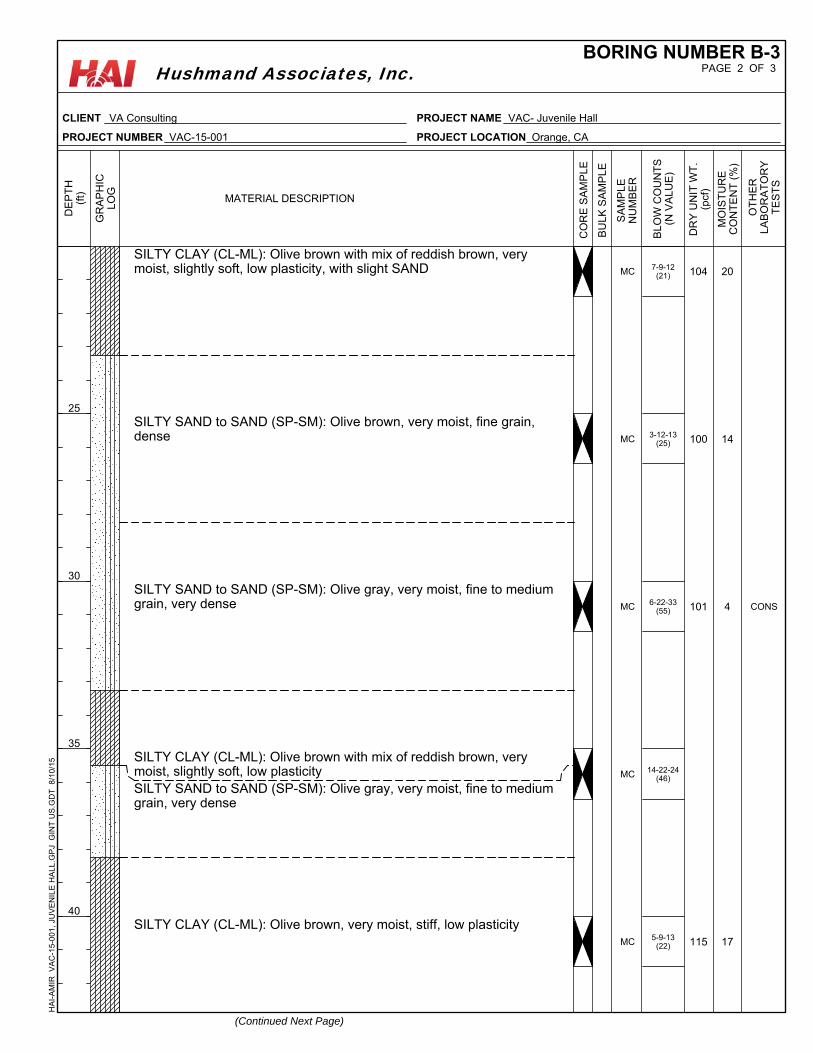
7-9-12(21)
3-12-13(25)
6-22-33(55)
14-22-24(46)
5-9-13(22)
SILTY CLAY (CL-ML): Olive brown with mix of reddish brown, verymoist, slightly soft, low plasticity, with slight SAND
SILTY SAND to SAND (SP-SM): Olive brown, very moist, fine grain,dense
SILTY SAND to SAND (SP-SM): Olive gray, very moist, fine to mediumgrain, very dense
SILTY CLAY (CL-ML): Olive brown with mix of reddish brown, verymoist, slightly soft, low plasticitySILTY SAND to SAND (SP-SM): Olive gray, very moist, fine to mediumgrain, very dense
SILTY CLAY (CL-ML): Olive brown, very moist, stiff, low plasticity
104
100
101
115
20
14
4
17
CONS
MC
MC
MC
MC
MC
MO
IST
UR
EC
ON
TE
NT
(%
)
BU
LK
SA
MP
LE
SA
MP
LE
NU
MB
ER
(Continued Next Page)
MATERIAL DESCRIPTION
OT
HE
RLA
BO
RA
TO
RY
TE
ST
S
25
30
35
40
DE
PT
H(f
t)
GR
AP
HIC
LO
G
DR
Y U
NIT
WT
.(p
cf)
CO
RE
SA
MP
LE
BL
OW
CO
UN
TS
(N V
AL
UE
)
PAGE 2 OF 3BORING NUMBER B-3
CLIENT VA Consulting
PROJECT NUMBER VAC-15-001
PROJECT NAME VAC- Juvenile Hall
PROJECT LOCATION Orange, CA
HA
I-A
MIR
V
AC
-15-
001,
JU
VE
NIL
E H
ALL
.GP
J G
INT
US
.GD
T
8/10
/15
Hushmand Associates, Inc.
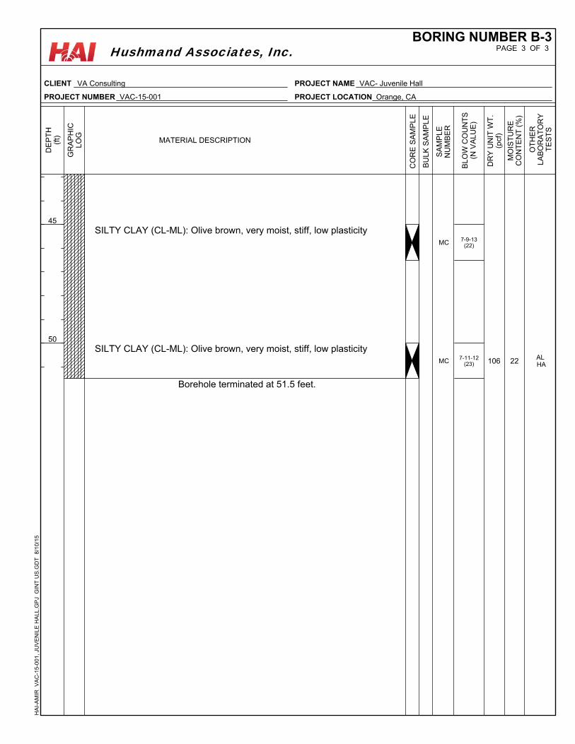
7-9-13(22)
7-11-12(23)
SILTY CLAY (CL-ML): Olive brown, very moist, stiff, low plasticity
SILTY CLAY (CL-ML): Olive brown, very moist, stiff, low plasticity
Borehole terminated at 51.5 feet.
106 22 AL HA
MC
MC
MO
IST
UR
EC
ON
TE
NT
(%
)
BU
LK
SA
MP
LE
SA
MP
LE
NU
MB
ER
MATERIAL DESCRIPTION
OT
HE
RLA
BO
RA
TO
RY
TE
ST
S
45
50
DE
PT
H(f
t)
GR
AP
HIC
LO
G
DR
Y U
NIT
WT
.(p
cf)
CO
RE
SA
MP
LE
BL
OW
CO
UN
TS
(N V
AL
UE
)
PAGE 3 OF 3BORING NUMBER B-3
CLIENT VA Consulting
PROJECT NUMBER VAC-15-001
PROJECT NAME VAC- Juvenile Hall
PROJECT LOCATION Orange, CA
HA
I-A
MIR
V
AC
-15-
001,
JU
VE
NIL
E H
ALL
.GP
J G
INT
US
.GD
T
8/10
/15
Hushmand Associates, Inc.
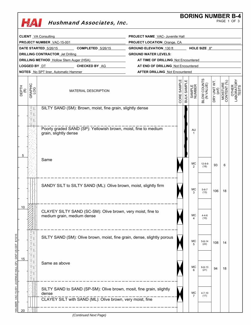
12-9-9(18)
5-6-7(13)
4-4-6(10)
5-8-14(22)
6-8-13(21)
4-7-10(17)
SILTY SAND (SM): Brown, moist, fine grain, slightly dense
Poorly graded SAND (SP): Yellowish brown, moist, fine to mediumgrain, slightly dense
Same
SANDY SILT to SILTY SAND (ML): Olive brown, moist, slightly firm
CLAYEY SILTY SAND (SC-SM): Olive brown, very moist, fine tomedium grain, medium dense
SILTY SAND (SM): Olive brown, moist, fine grain, dense, slightly porous
Same as above
SILTY SAND to SAND (SP-SM): Olive brown, mosit, fine grain, slightlydense
CLAYEY SILT with SAND (ML): Olive brown, very moist, fine
93
106
108
94
6
18
14
18
AU1
MC2
MC3
MC4
MC5
MC6
MC7
NOTES No SPT liner, Automatic Hammer
GROUND ELEVATION 130 ft
LOGGED BY DT
DATE STARTED 5/26/15
DRILLING METHOD Hollow Stem Auger (HSA) AT TIME OF DRILLING Not Encountered
AT END OF DRILLING Not Encountered
AFTER DRILLING Not Encountered
HOLE SIZE 8"
DRILLING CONTRACTOR Jet Drilling GROUND WATER LEVELS:
CHECKED BY AG
COMPLETED 5/26/15
MO
IST
UR
EC
ON
TE
NT
(%
)
BU
LK
SA
MP
LE
SA
MP
LE
NU
MB
ER
(Continued Next Page)
MATERIAL DESCRIPTION
OT
HE
RLA
BO
RA
TO
RY
TE
ST
S
5
10
15
20
DE
PT
H(f
t)
GR
AP
HIC
LO
G
DR
Y U
NIT
WT
.(p
cf)
CO
RE
SA
MP
LE
BL
OW
CO
UN
TS
(N V
AL
UE
)
PAGE 1 OF 3BORING NUMBER B-4
CLIENT VA Consulting
PROJECT NUMBER VAC-15-001
PROJECT NAME VAC- Juvenile Hall
PROJECT LOCATION Orange, CA
HA
I-A
MIR
V
AC
-15-
001,
JU
VE
NIL
E H
ALL
.GP
J G
INT
US
.GD
T
8/10
/15
Hushmand Associates, Inc.
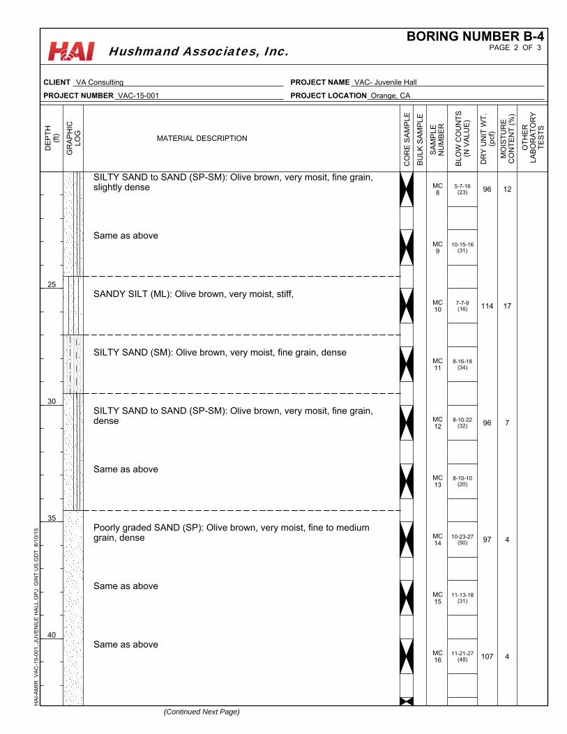
5-7-16(23)
10-15-16(31)
7-7-9(16)
8-16-18(34)
8-10-22(32)
8-10-10(20)
10-23-27(50)
11-13-18(31)
11-21-27(48)
SILTY SAND to SAND (SP-SM): Olive brown, very mosit, fine grain,slightly dense
Same as above
SANDY SILT (ML): Olive brown, very moist, stiff,
SILTY SAND (SM): Olive brown, very moist, fine grain, dense
SILTY SAND to SAND (SP-SM): Olive brown, very mosit, fine grain,dense
Same as above
Poorly graded SAND (SP): Olive brown, very moist, fine to mediumgrain, dense
Same as above
Same as above
96
114
96
97
107
12
17
7
4
4
MC8
MC9
MC10
MC11
MC12
MC13
MC14
MC15
MC16
MO
IST
UR
EC
ON
TE
NT
(%
)
BU
LK
SA
MP
LE
SA
MP
LE
NU
MB
ER
(Continued Next Page)
MATERIAL DESCRIPTION
OT
HE
RLA
BO
RA
TO
RY
TE
ST
S
25
30
35
40
DE
PT
H(f
t)
GR
AP
HIC
LO
G
DR
Y U
NIT
WT
.(p
cf)
CO
RE
SA
MP
LE
BL
OW
CO
UN
TS
(N V
AL
UE
)
PAGE 2 OF 3BORING NUMBER B-4
CLIENT VA Consulting
PROJECT NUMBER VAC-15-001
PROJECT NAME VAC- Juvenile Hall
PROJECT LOCATION Orange, CA
HA
I-A
MIR
V
AC
-15-
001,
JU
VE
NIL
E H
ALL
.GP
J G
INT
US
.GD
T
8/10
/15
Hushmand Associates, Inc.
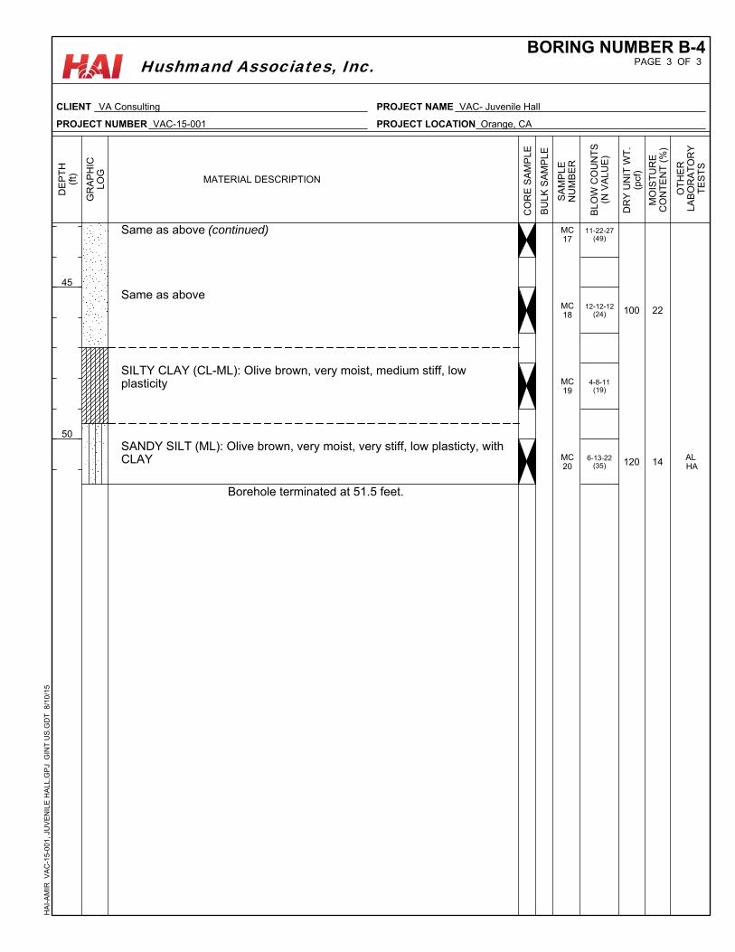
11-22-27(49)
12-12-12(24)
4-8-11(19)
6-13-22(35)
Same as above (continued)
Same as above
SILTY CLAY (CL-ML): Olive brown, very moist, medium stiff, lowplasticity
SANDY SILT (ML): Olive brown, very moist, very stiff, low plasticty, withCLAY
Borehole terminated at 51.5 feet.
100
120
22
14 AL HA
MC17
MC18
MC19
MC20
MO
IST
UR
EC
ON
TE
NT
(%
)
BU
LK
SA
MP
LE
SA
MP
LE
NU
MB
ER
MATERIAL DESCRIPTION
OT
HE
RLA
BO
RA
TO
RY
TE
ST
S
45
50
DE
PT
H(f
t)
GR
AP
HIC
LO
G
DR
Y U
NIT
WT
.(p
cf)
CO
RE
SA
MP
LE
BL
OW
CO
UN
TS
(N V
AL
UE
)
PAGE 3 OF 3BORING NUMBER B-4
CLIENT VA Consulting
PROJECT NUMBER VAC-15-001
PROJECT NAME VAC- Juvenile Hall
PROJECT LOCATION Orange, CA
HA
I-A
MIR
V
AC
-15-
001,
JU
VE
NIL
E H
ALL
.GP
J G
INT
US
.GD
T
8/10
/15
Hushmand Associates, Inc.
APPENDIX C LABORATORY TEST RESULTS
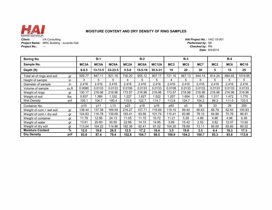
Client: VA Consulting HAI Project No.: VAC-15-001Project Name: MRC Building - Juvenile Hall Performed by: SEProject No.: --- Checked by: RN
Date: 6/5/2015
Boring No.
MC3A MC5A MC9A MC2A MC6A MC12A MC3 MC5 MC7 MC2 MC6 MC10
Depth (ft) 8-8.5 13-13.5 23-23.5 5.5-6 15.5-16 30.5-31 10 20 30 5 15 25
Total wt of rings and soil gr 509.77 847.11 821.16 730.20 955.12 907.17 721.16 967.13 844.14 814.24 884.65 1019.95Height of sample in 3 5 5 4 5 5 4 5 5 5 5 5
in 2.416 2.416 2.416 2.416 2.416 2.416 2.416 2.416 2.416 2.416 2.416 2.416cu.ft 0.0080 0.0133 0.0133 0.0106 0.0133 0.0133 0.0106 0.0133 0.0133 0.0133 0.0133 0.0133gr 130.17 216.96 216.96 173.57 216.96 216.96 173.57 216.96 216.96 216.96 216.96 216.96
lbs. 0.837 1.389 1.332 1.227 1.627 1.522 1.207 1.654 1.383 1.317 1.472 1.770pcf 105.1 104.7 100.4 115.6 122.7 114.7 113.8 124.7 104.2 99.3 111.0 133.5
p10 p11 L13 p23 p18 p16 p93 s3 39 33 29 200gr 138.44 137.38 169.59 216.27 107.71 116.69 119.10 99.40 80.63 68.78 82.83 100.83gr 124.83 116.78 139.09 193.41 93.56 101.74 115.41 83.98 78.10 64.96 70.76 86.91gr 11.79 12.56 24.13 11.05 11.15 10.72 11.21 5.29 4.99 4.96 4.96 6.39gr 13.61 20.60 30.50 22.86 14.15 14.95 3.69 15.42 2.53 3.82 12.07 13.92gr 113.04 104.22 114.96 182.36 82.41 91.02 104.20 78.69 73.11 60.00 65.80 80.52% 12.0 19.8 26.5 12.5 17.2 16.4 3.5 19.6 3.5 6.4 18.3 17.3
pcf 93.8 87.4 79.4 102.8 104.7 98.5 109.9 104.2 100.7 93.3 93.8 113.8
B-3 B-4
MOISTURE CONTENT AND DRY DENSITY OF RING SAMPLES
Sample No.
Diameter of sampleVolume of sample
Container No.
B-2
Weight of containerWeight of water
Weight of cont.+ wet soil
B-1
Weight of ringsWeight of soilWet Density
Weight of cont.+ dry soil
Weight of dry soilMoisture ContentDry Density
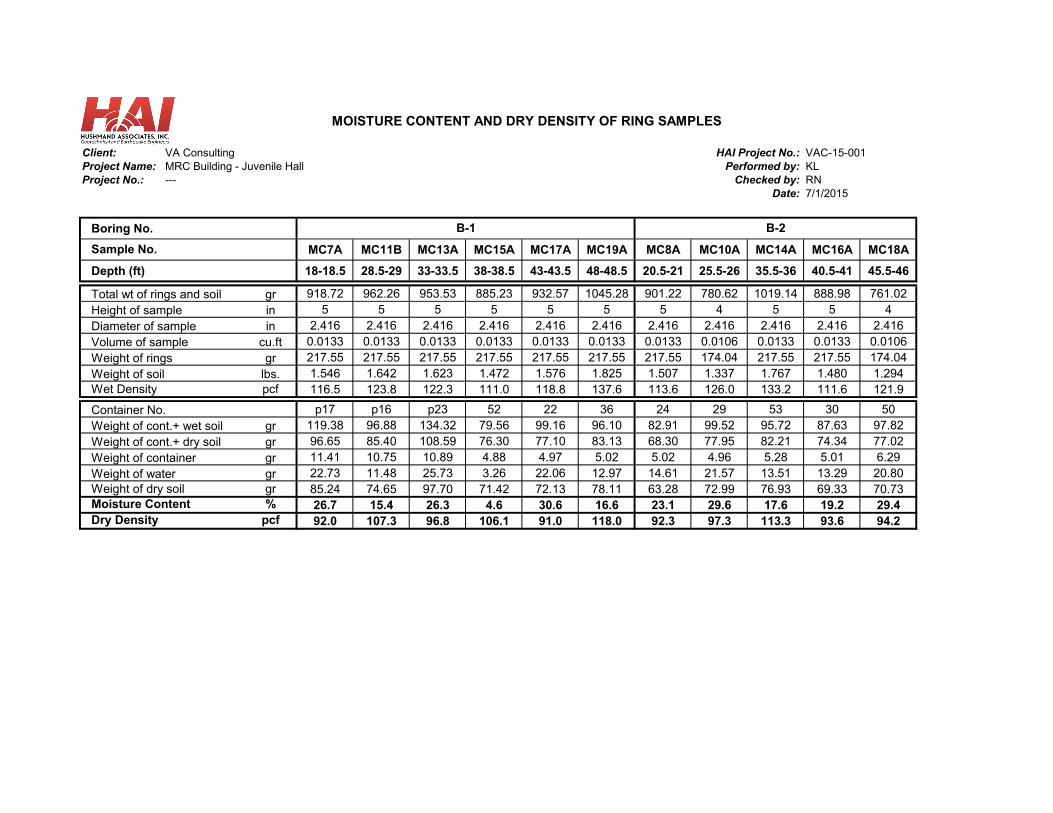
Client: VA Consulting HAI Project No.: VAC-15-001Project Name: MRC Building - Juvenile Hall Performed by: KLProject No.: --- Checked by: RN
Date: 7/1/2015
Boring No.
MC7A MC11B MC13A MC15A MC17A MC19A MC8A MC10A MC14A MC16A MC18A
Depth (ft) 18-18.5 28.5-29 33-33.5 38-38.5 43-43.5 48-48.5 20.5-21 25.5-26 35.5-36 40.5-41 45.5-46
Total wt of rings and soil gr 918.72 962.26 953.53 885.23 932.57 1045.28 901.22 780.62 1019.14 888.98 761.02Height of sample in 5 5 5 5 5 5 5 4 5 5 4
in 2.416 2.416 2.416 2.416 2.416 2.416 2.416 2.416 2.416 2.416 2.416cu.ft 0.0133 0.0133 0.0133 0.0133 0.0133 0.0133 0.0133 0.0106 0.0133 0.0133 0.0106gr 217.55 217.55 217.55 217.55 217.55 217.55 217.55 174.04 217.55 217.55 174.04
lbs. 1.546 1.642 1.623 1.472 1.576 1.825 1.507 1.337 1.767 1.480 1.294pcf 116.5 123.8 122.3 111.0 118.8 137.6 113.6 126.0 133.2 111.6 121.9
p17 p16 p23 52 22 36 24 29 53 30 50gr 119.38 96.88 134.32 79.56 99.16 96.10 82.91 99.52 95.72 87.63 97.82gr 96.65 85.40 108.59 76.30 77.10 83.13 68.30 77.95 82.21 74.34 77.02gr 11.41 10.75 10.89 4.88 4.97 5.02 5.02 4.96 5.28 5.01 6.29gr 22.73 11.48 25.73 3.26 22.06 12.97 14.61 21.57 13.51 13.29 20.80gr 85.24 74.65 97.70 71.42 72.13 78.11 63.28 72.99 76.93 69.33 70.73% 26.7 15.4 26.3 4.6 30.6 16.6 23.1 29.6 17.6 19.2 29.4
pcf 92.0 107.3 96.8 106.1 91.0 118.0 92.3 97.3 113.3 93.6 94.2
Weight of waterWeight of dry soil
Wet Density
B-2B-1
Moisture ContentDry Density
Container No.Weight of cont.+ wet soilWeight of cont.+ dry soilWeight of container
MOISTURE CONTENT AND DRY DENSITY OF RING SAMPLES
Sample No.
Diameter of sampleVolume of sampleWeight of ringsWeight of soil
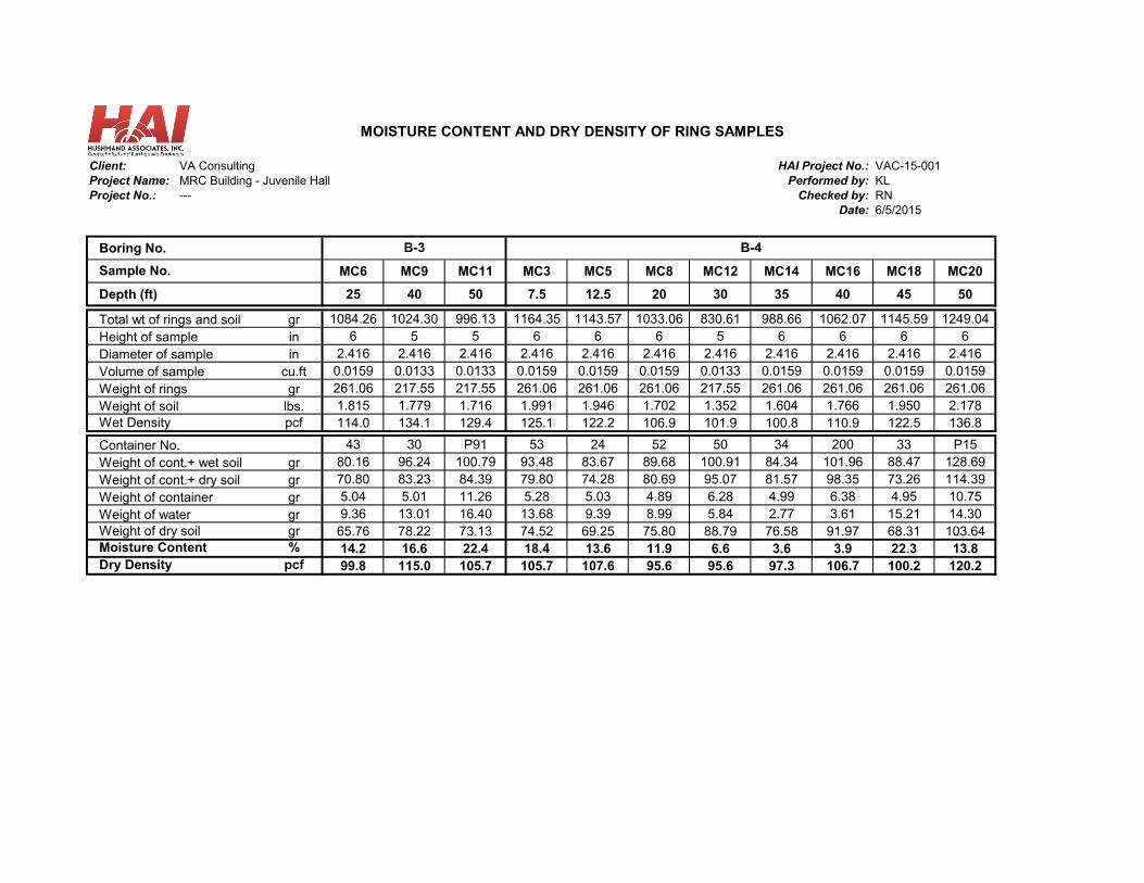
Client: VA Consulting HAI Project No.: VAC-15-001Project Name: MRC Building - Juvenile Hall Performed by: KLProject No.: --- Checked by: RN
Date: 6/5/2015
Boring No.
MC6 MC9 MC11 MC3 MC5 MC8 MC12 MC14 MC16 MC18 MC20
Depth (ft) 25 40 50 7.5 12.5 20 30 35 40 45 50
Total wt of rings and soil gr 1084.26 1024.30 996.13 1164.35 1143.57 1033.06 830.61 988.66 1062.07 1145.59 1249.04Height of sample in 6 5 5 6 6 6 5 6 6 6 6
in 2.416 2.416 2.416 2.416 2.416 2.416 2.416 2.416 2.416 2.416 2.416cu.ft 0.0159 0.0133 0.0133 0.0159 0.0159 0.0159 0.0133 0.0159 0.0159 0.0159 0.0159gr 261.06 217.55 217.55 261.06 261.06 261.06 217.55 261.06 261.06 261.06 261.06
lbs. 1.815 1.779 1.716 1.991 1.946 1.702 1.352 1.604 1.766 1.950 2.178pcf 114.0 134.1 129.4 125.1 122.2 106.9 101.9 100.8 110.9 122.5 136.8
43 30 P91 53 24 52 50 34 200 33 P15gr 80.16 96.24 100.79 93.48 83.67 89.68 100.91 84.34 101.96 88.47 128.69gr 70.80 83.23 84.39 79.80 74.28 80.69 95.07 81.57 98.35 73.26 114.39gr 5.04 5.01 11.26 5.28 5.03 4.89 6.28 4.99 6.38 4.95 10.75gr 9.36 13.01 16.40 13.68 9.39 8.99 5.84 2.77 3.61 15.21 14.30gr 65.76 78.22 73.13 74.52 69.25 75.80 88.79 76.58 91.97 68.31 103.64% 14.2 16.6 22.4 18.4 13.6 11.9 6.6 3.6 3.9 22.3 13.8
pcf 99.8 115.0 105.7 105.7 107.6 95.6 95.6 97.3 106.7 100.2 120.2
Weight of cont.+ dry soilWeight of containerWeight of waterWeight of dry soilMoisture ContentDry Density
Weight of ringsWeight of soilWet Density
Container No.Weight of cont.+ wet soil
MOISTURE CONTENT AND DRY DENSITY OF RING SAMPLES
Sample No.
Diameter of sampleVolume of sample
B-3 B-4
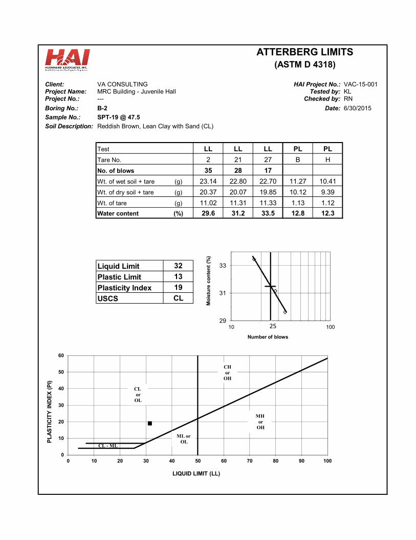
Client: VA CONSULTING VAC-15-001Project Name: MRC Building - Juvenile Hall KLProject No.: --- RN
Boring No.: B-2 Date:
Sample No.: SPT-19 @ 47.5
Soil Description: Reddish Brown, Lean Clay with Sand (CL)
LL LL LL PL PL
2 21 27 B H
35 28 17
Wt. of wet soil + tare (g) 23.14 22.80 22.70 11.27 10.41
Wt. of dry soil + tare (g) 20.37 20.07 19.85 10.12 9.39
Wt. of tare (g) 11.02 11.31 11.33 1.13 1.12
Water content (%) 29.6 31.2 33.5 12.8 12.3
Liquid Limit 32
Plastic Limit 13
Plasticity Index 19
CL
Checked by:
USCS
No. of blows
Tare No.
Test
ATTERBERG LIMITS(ASTM D 4318)
6/30/2015
HAI Project No.:Tested by:
0
10
20
30
40
50
60
0 10 20 30 40 50 60 70 80 90 100
PL
AS
TIC
ITY
IN
DE
X (
PI)
LIQUID LIMIT (LL)
CL - ML
CL or
OL
CH or
OH
ML orOL
MHor
OH
29
31
33
10 100
Mo
istu
re c
on
ten
t (%
)
Number of blows
25
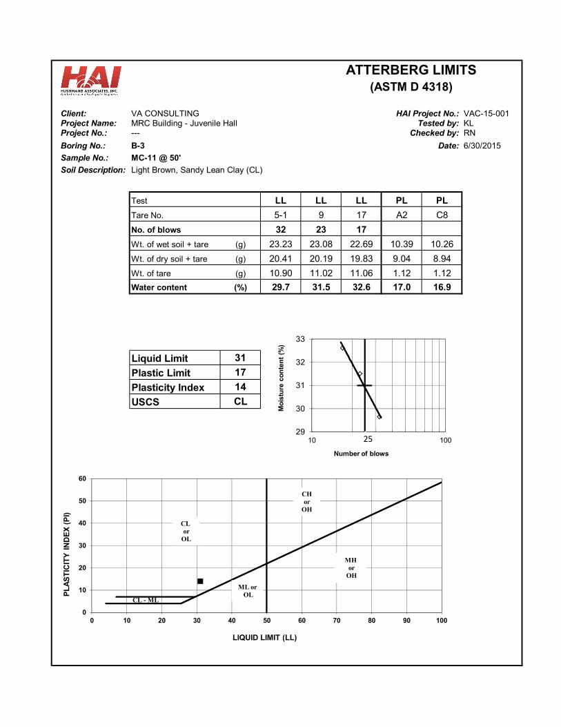
Client: VA CONSULTING VAC-15-001Project Name: MRC Building - Juvenile Hall KLProject No.: --- RN
Boring No.: B-3 Date:
Sample No.: MC-11 @ 50'
Soil Description: Light Brown, Sandy Lean Clay (CL)
LL LL LL PL PL
5-1 9 17 A2 C8
32 23 17
Wt. of wet soil + tare (g) 23.23 23.08 22.69 10.39 10.26
Wt. of dry soil + tare (g) 20.41 20.19 19.83 9.04 8.94
Wt. of tare (g) 10.90 11.02 11.06 1.12 1.12
Water content (%) 29.7 31.5 32.6 17.0 16.9
Liquid Limit 31
Plastic Limit 17
Plasticity Index 14
CL
6/30/2015
HAI Project No.:Tested by:
Checked by:
USCS
No. of blows
Tare No.
Test
ATTERBERG LIMITS(ASTM D 4318)
0
10
20
30
40
50
60
0 10 20 30 40 50 60 70 80 90 100
PL
AS
TIC
ITY
IN
DE
X (
PI)
LIQUID LIMIT (LL)
CL - ML
CL or
OL
CH or
OH
ML orOL
MHor
OH
29
30
31
32
33
10 100
Mo
istu
re c
on
ten
t (%
)
Number of blows
25
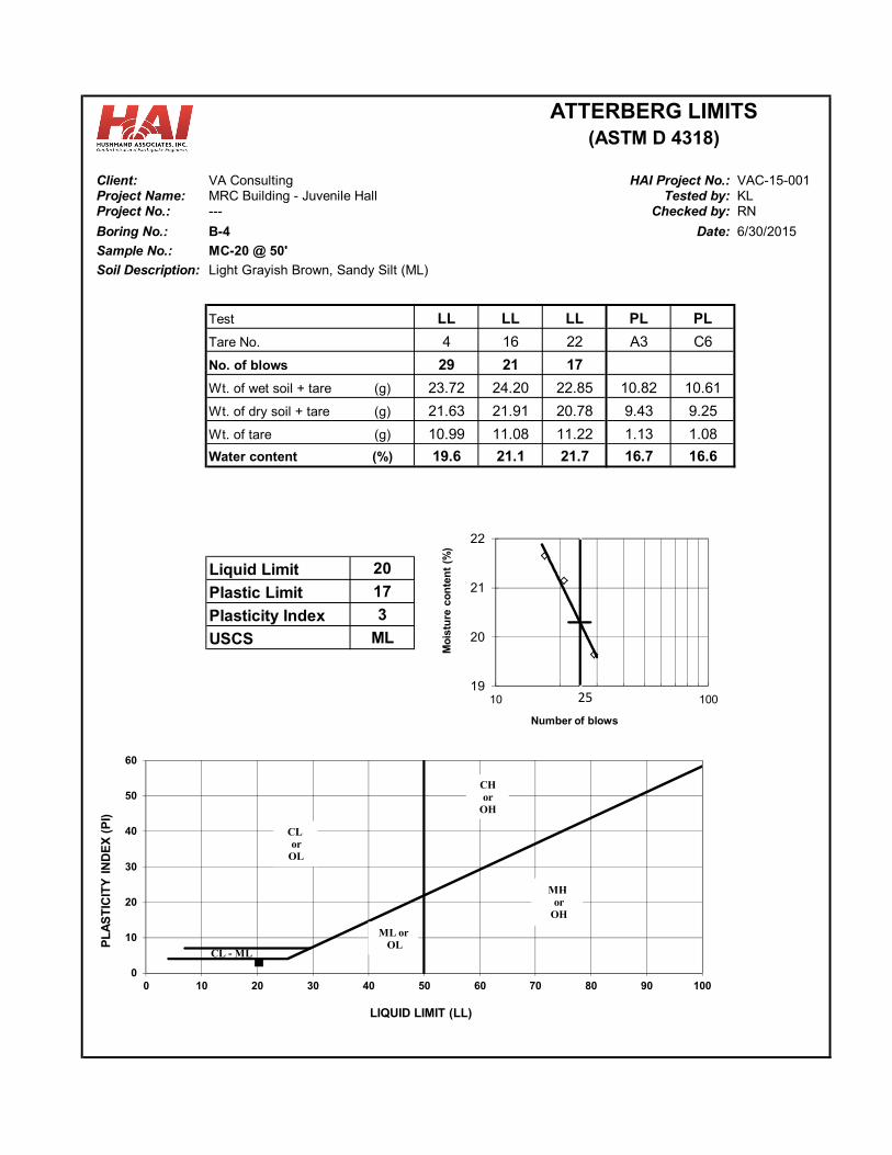
Client: VA Consulting VAC-15-001Project Name: MRC Building - Juvenile Hall KLProject No.: --- RN
Boring No.: B-4 Date:
Sample No.: MC-20 @ 50'
Soil Description: Light Grayish Brown, Sandy Silt (ML)
LL LL LL PL PL
4 16 22 A3 C6
29 21 17
Wt. of wet soil + tare (g) 23.72 24.20 22.85 10.82 10.61
Wt. of dry soil + tare (g) 21.63 21.91 20.78 9.43 9.25
Wt. of tare (g) 10.99 11.08 11.22 1.13 1.08
Water content (%) 19.6 21.1 21.7 16.7 16.6
Liquid Limit 20
Plastic Limit 17
Plasticity Index 3
ML
6/30/2015
HAI Project No.:Tested by:
Checked by:
USCS
No. of blows
Tare No.
Test
ATTERBERG LIMITS(ASTM D 4318)
0
10
20
30
40
50
60
0 10 20 30 40 50 60 70 80 90 100
PL
AS
TIC
ITY
IN
DE
X (
PI)
LIQUID LIMIT (LL)
CL - ML
CL or
OL
CH or
OH
ML orOL
MHor
OH
19
20
21
22
10 100
Mo
istu
re c
on
ten
t (%
)
Number of blows
25
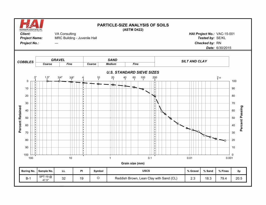
VA Consulting VAC-15-001MRC Building - Juvenile Hall SE/KL
RN
Date:
Boring No. Sample No. LL PI Symbol % Gravel % Sand % Fines 2µ
B-1SPT-19 @
47.5'' 32 19 2.3 18.3 79.4 20.5
U.S. STANDARD SIEVE SIZES
6/30/2015
USCS
Reddish Brown, Lean Clay with Sand (CL)
PARTICLE-SIZE ANALYSIS OF SOILS
---
(ASTM D422)Client: HAI Project No.:
Tested by:Project Name:
Project No.: Checked by:
SANDCoarse Medium Fine
0
10
20
30
40
50
60
70
80
90
100 0
10
20
30
40
50
60
70
80
90
100
0.0010.010.1110100
Per
cen
t R
etai
ned
Per
cen
t P
assi
ng
Grain size (mm)
GRAVELCoarse Fine
SILT AND CLAYCOBBLES
3" 4 10 20 40 100 2 μ200603/4" 3/8"1.5"
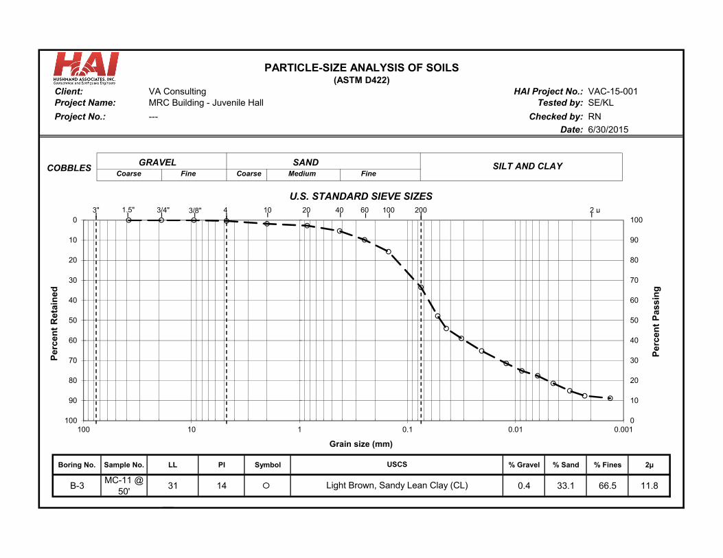
VA Consulting VAC-15-001MRC Building - Juvenile Hall SE/KL
RN
Date:
Boring No. Sample No. LL PI Symbol % Gravel % Sand % Fines 2µ
B-3MC-11 @
50'31 14 0.4 33.1 66.5 11.8
U.S. STANDARD SIEVE SIZES
6/30/2015
USCS
Light Brown, Sandy Lean Clay (CL)
PARTICLE-SIZE ANALYSIS OF SOILS
---
(ASTM D422)Client: HAI Project No.:
Tested by:Project Name:
Project No.: Checked by:
SANDCoarse Medium Fine
0
10
20
30
40
50
60
70
80
90
100 0
10
20
30
40
50
60
70
80
90
100
0.0010.010.1110100
Per
cen
t R
etai
ned
Per
cen
t P
assi
ng
Grain size (mm)
GRAVELCoarse Fine
SILT AND CLAYCOBBLES
3" 4 10 20 40 100 2 μ200603/4" 3/8"1.5"
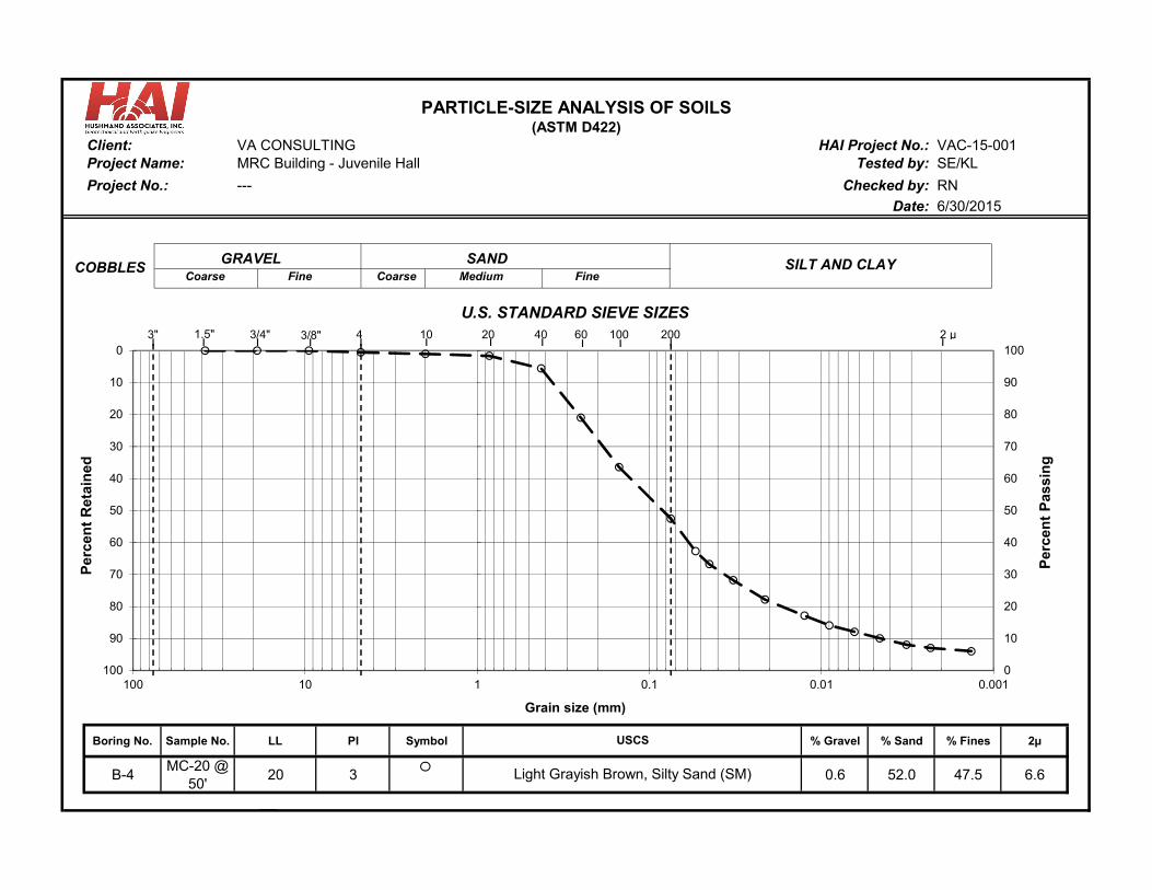
VA CONSULTING VAC-15-001MRC Building - Juvenile Hall SE/KL
RN
Date:
Boring No. Sample No. LL PI Symbol % Gravel % Sand % Fines 2µ
B-4MC-20 @
50'20 3 0.6 52.0 47.5 6.6
PARTICLE-SIZE ANALYSIS OF SOILS
---
(ASTM D422)Client: HAI Project No.:
Tested by:Project Name:
Project No.: Checked by:
U.S. STANDARD SIEVE SIZES
6/30/2015
USCS
Light Grayish Brown, Silty Sand (SM)
SANDCoarse Medium Fine
0
10
20
30
40
50
60
70
80
90
100 0
10
20
30
40
50
60
70
80
90
100
0.0010.010.1110100
Per
cen
t R
etai
ned
Per
cen
t P
assi
ng
Grain size (mm)
GRAVELCoarse Fine
SILT AND CLAYCOBBLES
3" 4 10 20 40 100 2 μ200603/4" 3/8"1.5"
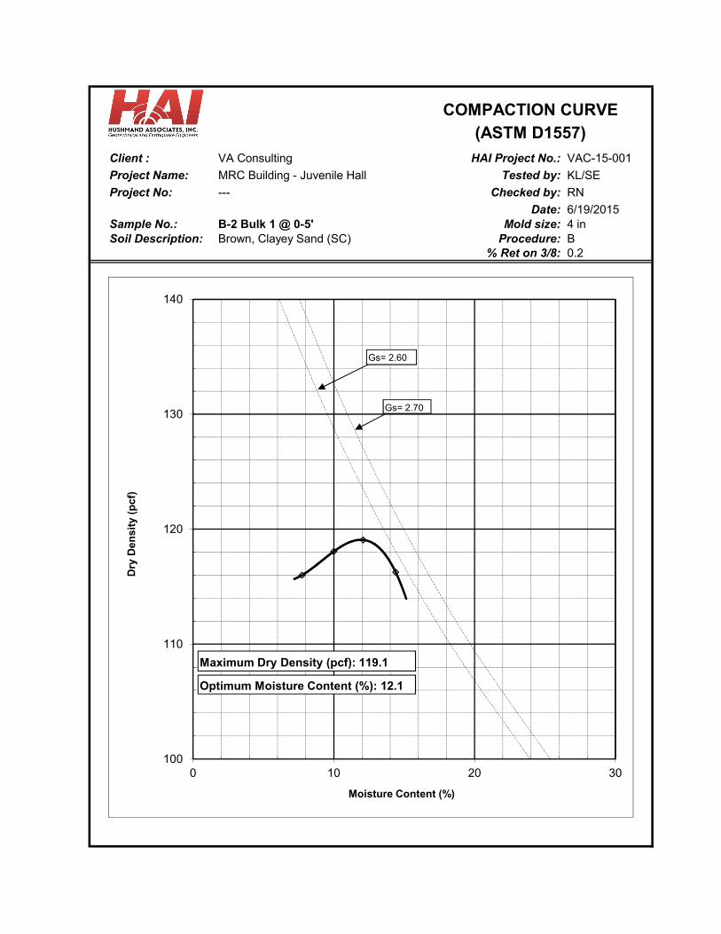
Client : VA Consulting VAC-15-001
Project Name: MRC Building - Juvenile Hall Tested by: KL/SE
Project No: --- RN
Date: 6/19/2015Sample No.: B-2 Bulk 1 @ 0-5' Mold size: 4 inSoil Description: Procedure: B
0.2Brown, Clayey Sand (SC)
COMPACTION CURVE(ASTM D1557)
HAI Project No.:
% Ret on 3/8:
Checked by:
100
110
120
130
140
0 10 20 30
Dry
De
ns
ity
(pc
f)
Moisture Content (%)
Gs= 2.70
Gs= 2.60
Maximum Dry Density (pcf): 119.1
Optimum Moisture Content (%): 12.1
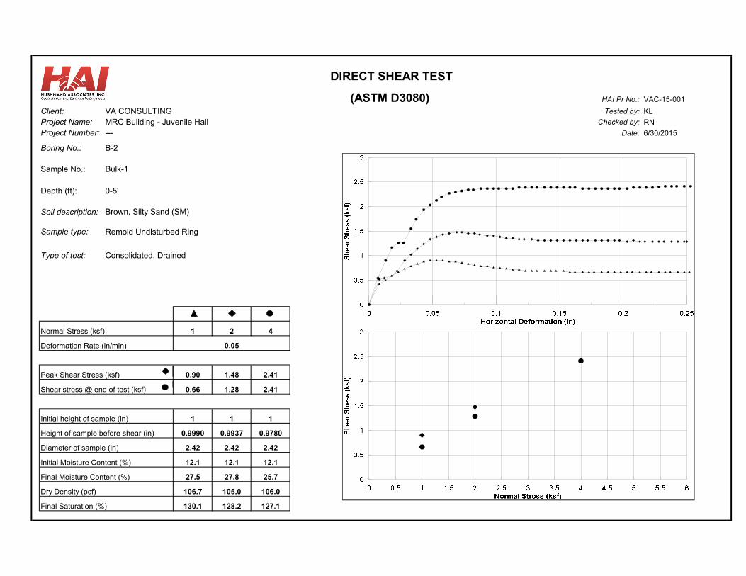
VAC-15-001
Client: VA CONSULTING KL
Project Name: MRC Building - Juvenile Hall RN
Project Number: --- Date: 6/30/2015
Boring No.: B-2
Sample No.: Bulk-1
Depth (ft): 0-5'
Soil description: Brown, Silty Sand (SM)
Sample type: Remold Undisturbed Ring
Type of test: Consolidated, Drained
Normal Stress (ksf) 1 2 4
Deformation Rate (in/min)
Peak Shear Stress (ksf) 0.90 1.48 2.41
Shear stress @ end of test (ksf) 0.66 1.28 2.41
Initial height of sample (in) 1 1 1
Height of sample before shear (in) 0.9990 0.9937 0.9780
Diameter of sample (in) 2.42 2.42 2.42
Initial Moisture Content (%) 12.1 12.1 12.1
Final Moisture Content (%) 27.5 27.8 25.7
Dry Density (pcf) 106.7 105.0 106.0
Final Saturation (%) 130.1 128.2 127.1
DIRECT SHEAR TEST
HAI Pr No.:Tested by:
Checked by:
0.05
(ASTM D3080)

Client : VA ConsultingMRC Building - Juvenile Hall KL/SE--- RN
Date:Boring No.: B-1 MC-3A Depth: 8-8.5'
Brown, Silty Sand (SM)Undisturbed ring
H (in)Hs (in)Hw (in)Ha (in)
(pcf)(%)(%)
Load δH H Voids Consol. t50 av Mv
(ksf) (in) (in) (in) (%) (sec) (ksf) (ksf)
0.1 ------- 0.9905 0.441 0.802 0
0.25 0.0051 0.9854 0.436 0.793 0.5 6.2E-02 3.5E-02
0.5 0.0104 0.9801 0.430 0.783 1.0 3.9E-02 2.2E-02
1 0.0240 0.9665 0.417 0.758 2.4 4.9E-02 2.8E-02
1 0.0408 0.9497 0.400 0.728 4.1
2 0.0683 0.9222 0.372 0.678 6.9 5.0E-02 3.0E-02
4 0.0944 0.8961 0.346 0.630 9.5 2.4E-02 1.5E-02
8 0.1271 0.8634 0.314 0.571 12.8 1.5E-02 9.5E-03
2 0.1247 0.8658 0.316 0.575 12.6
0.5 0.1161 0.8744 0.325 0.591 11.7
0.268
106.9
97.321.3
Checked by:
18.1
0.3160.009
Final Total Weight
Initial Conditions
e
0.9905
Tested by:
(g)Initial Total Weight
0.87440.550
Unload
135.24
Saturation
Height0.550
0.173
Height of Solids
Project Name:Project No.:
131.64(g)
Sample No.:
VAC-15-001
Type of Sample:
Final Dry Weight
Water Content
Height of WaterHeight of AirDry Density 93.5
Soil Description:
UNLOAD
WATER ADDED
CONSOLIDATION TEST(ASTM D2435)
60.8
(g)111.50
7/1/2015
HAI Project No.:
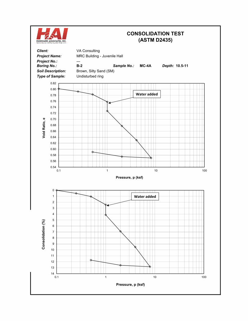
Client: VA Consulting
Project Name: MRC Building - Juvenile Hall
---Boring No.: B-2 MC-4A Depth: 10.5-11
Soil Description: Brown, Silty Sand (SM)
Undisturbed ring
CONSOLIDATION TEST(ASTM D2435)
Sample No.:
Type of Sample:
Project No.:
0.54
0.56
0.58
0.60
0.62
0.64
0.66
0.68
0.70
0.72
0.74
0.76
0.78
0.80
0.82
0.1 1 10 100
Vo
id R
atio
, e
Pressure, p (ksf)
0
1
2
3
4
5
6
7
8
9
10
11
12
13
140.1 1 10 100
Co
ns
olid
ati
on
(%
)
Pressure, p (ksf)
Water added
Water added
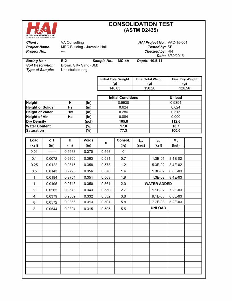
Client : VA ConsultingMRC Building - Juvenile Hall SE--- RN
Date:Boring No.: B-2 MC-4A Depth: 10.5-11
Brown, Silty Sand (SM)Undisturbed ring
H (in)Hs (in)Hw (in)Ha (in)
(pcf)(%)(%)
Load δH H Voids Consol. t50 av Mv
(ksf) (in) (in) (in) (%) (sec) (ksf) (ksf)
0.01 ------- 0.9938 0.370 0.593 0
0.1 0.0072 0.9866 0.363 0.581 0.7 1.3E-01 8.1E-02
0.25 0.0122 0.9816 0.358 0.573 1.2 5.3E-02 3.4E-02
0.5 0.0143 0.9795 0.356 0.570 1.4 1.3E-02 8.6E-03
1 0.0184 0.9754 0.351 0.563 1.9 1.3E-02 8.4E-03
1 0.0195 0.9743 0.350 0.561 2.0
2 0.0265 0.9673 0.343 0.550 2.7 1.1E-02 7.2E-03
4 0.0379 0.9559 0.332 0.532 3.8 9.1E-03 6.0E-03
8 0.0572 0.9366 0.313 0.501 5.8 7.7E-03 5.2E-03
2 0.0544 0.9394 0.315 0.505 5.5
0.286
112.6
100.018.7
Checked by:
17.0
0.3150.000
Final Total Weight
Initial Conditions
e
0.9938
Tested by:
(g)Initial Total Weight
0.93940.624
Unload
150.26
Saturation
Height0.624
0.084
Height of Solids
Project Name:Project No.:
148.03(g)
Sample No.:
VAC-15-001
Type of Sample:
Final Dry Weight
Water Content
Height of WaterHeight of AirDry Density 105.8
Soil Description:
UNLOAD
WATER ADDED
CONSOLIDATION TEST(ASTM D2435)
77.3
(g)126.56
6/30/2015
HAI Project No.:
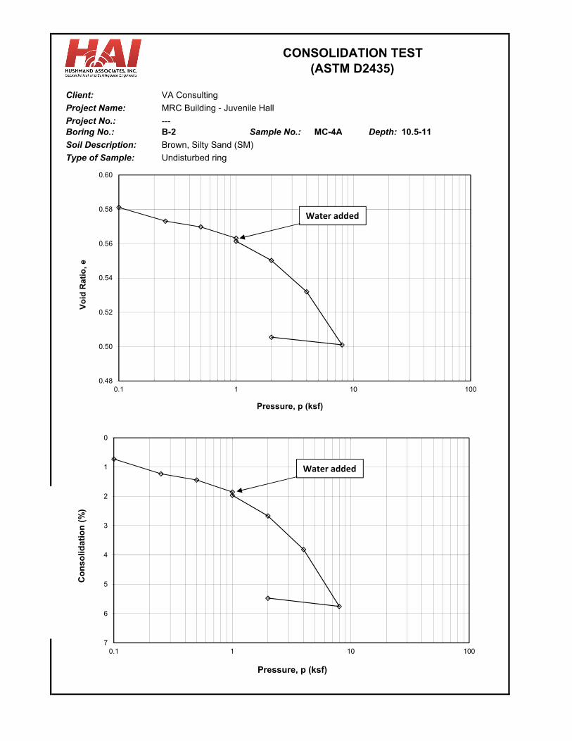
Client: VA Consulting
Project Name: MRC Building - Juvenile Hall
---Boring No.: B-2 MC-4A Depth: 10.5-11
Soil Description: Brown, Silty Sand (SM)
Undisturbed ring
CONSOLIDATION TEST(ASTM D2435)
Sample No.:
Type of Sample:
Project No.:
0.48
0.50
0.52
0.54
0.56
0.58
0.60
0.1 1 10 100
Vo
id R
ati
o,
e
Pressure, p (ksf)
0
1
2
3
4
5
6
70.1 1 10 100
Co
nso
lidat
ion
(%
)
Pressure, p (ksf)
Water added
Water added
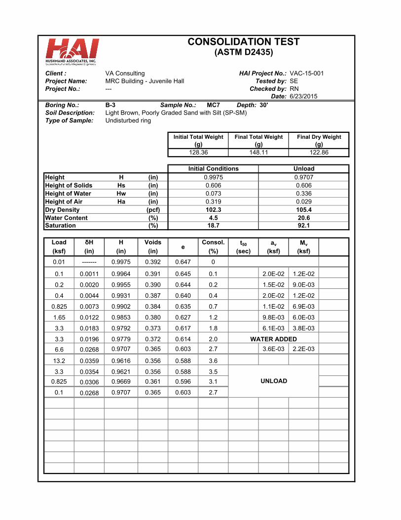
Client : VA ConsultingMRC Building - Juvenile Hall SE--- RN
Date:Boring No.: B-3 MC7 Depth: 30'
Light Brown, Poorly Graded Sand with Silt (SP-SM)Undisturbed ring
H (in)Hs (in)Hw (in)Ha (in)
(pcf)(%)(%)
Load δH H Voids Consol. t50 av Mv
(ksf) (in) (in) (in) (%) (sec) (ksf) (ksf)
0.01 ------- 0.9975 0.392 0.647 0
0.1 0.0011 0.9964 0.391 0.645 0.1 2.0E-02 1.2E-02
0.2 0.0020 0.9955 0.390 0.644 0.2 1.5E-02 9.0E-03
0.4 0.0044 0.9931 0.387 0.640 0.4 2.0E-02 1.2E-02
0.825 0.0073 0.9902 0.384 0.635 0.7 1.1E-02 6.9E-03
1.65 0.0122 0.9853 0.380 0.627 1.2 9.8E-03 6.0E-03
3.3 0.0183 0.9792 0.373 0.617 1.8 6.1E-03 3.8E-03
3.3 0.0196 0.9779 0.372 0.614 2.0
6.6 0.0268 0.9707 0.365 0.603 2.7 3.6E-03 2.2E-03
13.2 0.0359 0.9616 0.356 0.588 3.6
3.3 0.0354 0.9621 0.356 0.588 3.5
0.825 0.0306 0.9669 0.361 0.596 3.1
0.1 0.0268 0.9707 0.365 0.603 2.7
WATER ADDED
UNLOAD
CONSOLIDATION TEST(ASTM D2435)
18.7
(g)122.86
6/23/2015
HAI Project No.: VAC-15-001
Type of Sample:
Final Dry Weight
Water Content
Height of WaterHeight of AirDry Density 102.3
Soil Description:
Saturation
Height0.606
0.319
Height of Solids
Project Name:Project No.:
128.36(g)
Sample No.:
Tested by:
(g)Initial Total Weight
0.97070.606
Unload
148.11
Checked by:
4.5
0.3360.029
Final Total Weight
Initial Conditions
e
0.9975
0.073
105.4
92.120.6
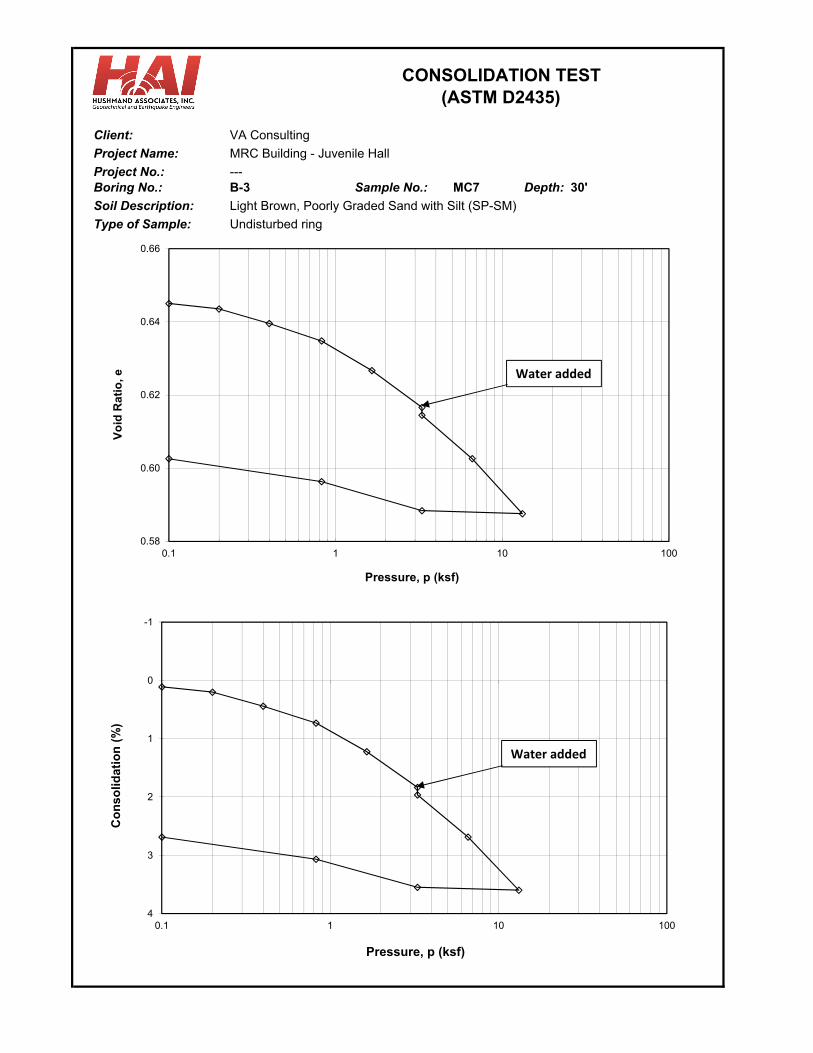
Client: VA Consulting
Project Name: MRC Building - Juvenile Hall
---Boring No.: B-3 MC7 Depth: 30'
Soil Description: Light Brown, Poorly Graded Sand with Silt (SP-SM)
Undisturbed ring
CONSOLIDATION TEST(ASTM D2435)
Sample No.:
Type of Sample:
Project No.:
0.58
0.60
0.62
0.64
0.66
0.1 1 10 100
Vo
id R
ati
o,
e
Pressure, p (ksf)
-1
0
1
2
3
40.1 1 10 100
Co
nso
lidat
ion
(%
)
Pressure, p (ksf)
Water added
Water added
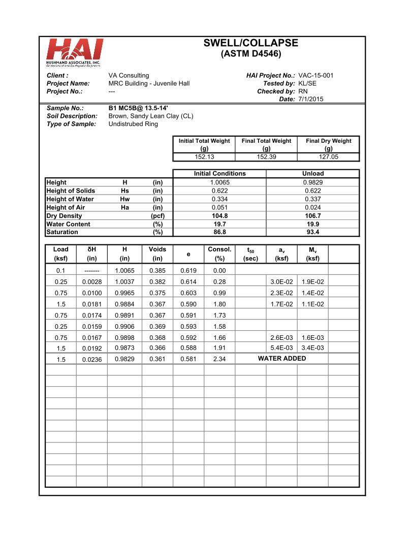
VA ConsultingMRC Building - Juvenile Hall KL/SE--- RN
Date:
Brown, Sandy Lean Clay (CL)Undistrubed Ring
H (in)Hs (in)Hw (in)Ha (in)
(pcf)(%)(%)
Load δH H Voids Consol. t50 av Mv
(ksf) (in) (in) (in) (%) (sec) (ksf) (ksf)
0.1 ------- 1.0065 0.385 0.619 0.00
0.25 0.0028 1.0037 0.382 0.614 0.28 3.0E-02 1.9E-02
0.75 0.0100 0.9965 0.375 0.603 0.99 2.3E-02 1.4E-02
1.5 0.0181 0.9884 0.367 0.590 1.80 1.7E-02 1.1E-02
0.75 0.0174 0.9891 0.367 0.591 1.73
0.25 0.0159 0.9906 0.369 0.593 1.58
0.75 0.0167 0.9898 0.368 0.592 1.66 2.6E-03 1.6E-03
1.5 0.0192 0.9873 0.366 0.588 1.91 5.4E-03 3.4E-03
1.5 0.0236 0.9829 0.361 0.581 2.34
SWELL/COLLAPSE(ASTM D4546)
86.8
0.622
HAI Project No.:Tested by:
93.4
152.39
7/1/2015
VAC-15-001
Final Dry Weight
Water ContentSaturation
Height
Sample No.: B1 MC5B@ 13.5-14'
0.622
152.13
Client :
127.05(g)
0.9829
Dry Density
Height of Solids
(g)
Height of Water
Unload
Project Name:Project No.:
Soil Description:
Height of Air
(g)Initial Total Weight
1.0065
Checked by:
0.051
Type of Sample:
e
WATER ADDED
19.7
0.3370.024
Final Total Weight
Initial Conditions
19.9104.8
0.334
106.7
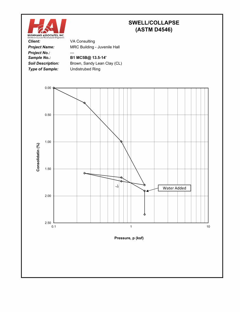
Client: VA Consulting
Project Name:
---Sample No.: B1 MC5B@ 13.5-14'
Soil Description: Brown, Sandy Lean Clay (CL)
Undistrubed RingType of Sample:
Project No.:
SWELL/COLLAPSE(ASTM D4546)
MRC Building - Juvenile Hall
0.00
0.50
1.00
1.50
2.00
2.500.1 1 10
Co
ns
olid
ati
n (
%)
Pressure, p (ksf)
Water Added
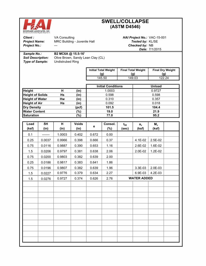
VA ConsultingMRC Building - Juvenile Hall KL/SE--- NB
Date:
Olive Brown, Sandy Lean Clay (CL)Undistrubed Ring
H (in)Hs (in)Hw (in)Ha (in)
(pcf)(%)(%)
Load δH H Voids Consol. t50 av Mv
(ksf) (in) (in) (in) (%) (sec) (ksf) (ksf)
0.1 ------- 1.0003 0.402 0.672 0.00
0.25 0.0037 0.9966 0.398 0.666 0.37 4.1E-02 2.5E-02
0.75 0.0116 0.9887 0.390 0.653 1.16 2.6E-02 1.6E-02
1.5 0.0206 0.9797 0.381 0.638 2.06 2.0E-02 1.2E-02
0.75 0.0200 0.9803 0.382 0.639 2.00
0.25 0.0186 0.9817 0.383 0.641 1.86
0.75 0.0196 0.9807 0.382 0.639 1.96 3.3E-03 2.0E-03
1.5 0.0227 0.9776 0.379 0.634 2.27 6.9E-03 4.2E-03
1.5 0.0276 0.9727 0.374 0.626 2.76 WATER ADDED
19.0
0.3570.018
Final Total Weight
Initial Conditions
21.9101.5
0.310
104.4
e
Project Name:Project No.:
Soil Description:
Height of Air
(g)Initial Total Weight
1.0003
Checked by:
0.092
Type of Sample:
Client :
122.24(g)
0.9727
Dry Density
Height of Solids
(g)
Height of Water
Unload
Final Dry Weight
Water ContentSaturation
Height
Sample No.: B2 MC6A @ 15.5-16'
0.598
145.50
SWELL/COLLAPSE(ASTM D4546)
77.0
0.598
HAI Project No.:Tested by:
95.2
149.03
7/1/2015
VAC-15-001
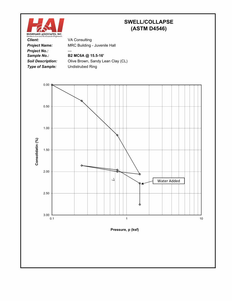
Client: VA Consulting
Project Name:
---Sample No.: B2 MC6A @ 15.5-16'
Soil Description: Olive Brown, Sandy Lean Clay (CL)
Undistrubed RingType of Sample:
Project No.:
SWELL/COLLAPSE(ASTM D4546)
MRC Building - Juvenile Hall
0.00
0.50
1.00
1.50
2.00
2.50
3.000.1 1 10
Co
ns
olid
ati
n (
%)
Pressure, p (ksf)
Water Added
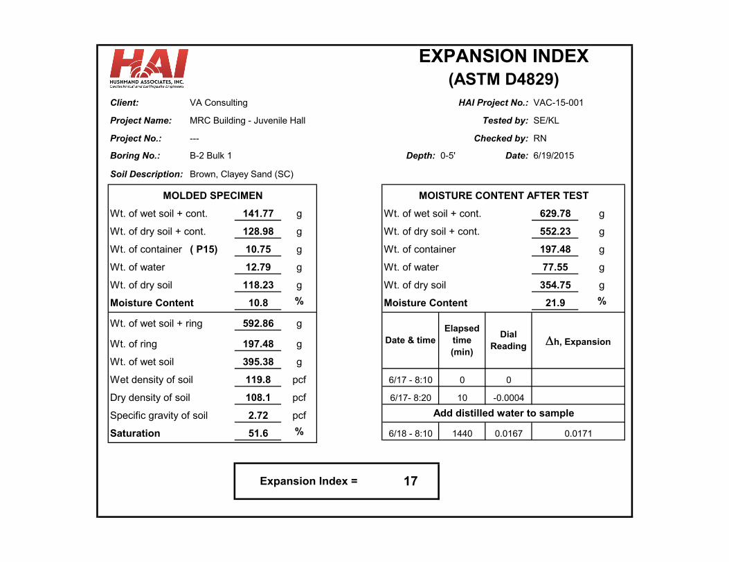
Client: VA Consulting VAC-15-001
Project Name: MRC Building - Juvenile Hall SE/KL
Project No.: --- RN
Boring No.: B-2 Bulk 1 Depth: 0-5' Date:
Brown, Clayey Sand (SC)
141.77 g 629.78 g
128.98 g 552.23 g
( P15) 10.75 g 197.48 g
12.79 g 77.55 g
118.23 g 354.75 g
10.8 % 21.9 %
Wt. of wet soil + ring 592.86 g
Wt. of ring 197.48 g
Wt. of wet soil 395.38 g
Wet density of soil 119.8 pcf 6/17 - 8:10 0 0
Dry density of soil 108.1 pcf 6/17- 8:20 10 -0.0004
Specific gravity of soil 2.72 pcf
51.6 % 6/18 - 8:10 1440 0.0167 0.0171
Checked by:
MOLDED SPECIMEN
Wt. of wet soil + cont.
Wt. of container
Wt. of dry soil
6/19/2015
Date & time
EXPANSION INDEX
Wt. of dry soil + cont.
Soil Description:
HAI Project No.:
Tested by:
(ASTM D4829)
Elapsed time (min)
Dial Reading h, Expansion
MOISTURE CONTENT AFTER TEST
Wt. of wet soil + cont.
Wt. of dry soil + cont.
Wt. of container
Add distilled water to sample
Expansion Index = 17
Wt. of water Wt. of water
Wt. of dry soil
Moisture Content
Saturation
Moisture Content
431 West Baseline Road ∙ Claremont, CA 91711Phone: 909.962.5485 ∙ Fax: 909.626.3316
DATE:
ATTENTION: Ben Hushmand
TO:
SUBJECT:
COMMENTS:
James T. KeeganLaboratory Services Manager
TRANSMITTAL LETTER
July 1, 2015
VAC-Juvenile Hall
Enclosed are the results for the subject project.
Hushmand Associates250 Goddard
Laboratory Test Data
Irvine, CA 92618
Your #VAC-15-001, HDR Lab #15-0460LAB
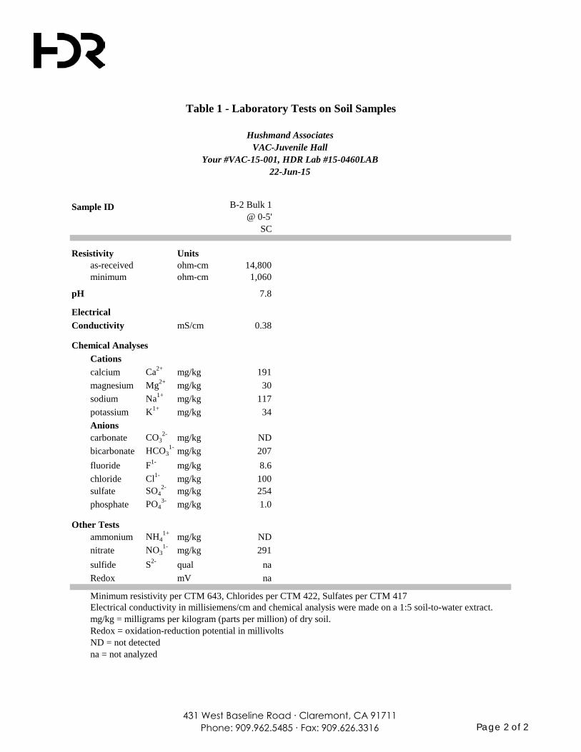
431 West Baseline Road ∙ Claremont, CA 91711Phone: 909.962.5485 ∙ Fax: 909.626.3316 Page 2 of 2
Sample ID B-2 Bulk 1@ 0-5'
SC
Resistivity Unitsas-received ohm-cm 14,800minimum ohm-cm 1,060
pH 7.8
ElectricalConductivity mS/cm 0.38
Chemical AnalysesCationscalcium Ca2+ mg/kg 191magnesium Mg2+ mg/kg 30sodium Na1+ mg/kg 117potassium K1+ mg/kg 34Anionscarbonate CO3
2- mg/kg NDbicarbonate HCO3
1- mg/kg 207fluoride F1- mg/kg 8.6chloride Cl1- mg/kg 100sulfate SO4
2- mg/kg 254phosphate PO4
3- mg/kg 1.0
Other Testsammonium NH4
1+ mg/kg NDnitrate NO3
1- mg/kg 291sulfide S2- qual naRedox mV na
Minimum resistivity per CTM 643, Chlorides per CTM 422, Sulfates per CTM 417Electrical conductivity in millisiemens/cm and chemical analysis were made on a 1:5 soil-to-water extract.mg/kg = milligrams per kilogram (parts per million) of dry soil.Redox = oxidation-reduction potential in millivoltsND = not detectedna = not analyzed
Table 1 - Laboratory Tests on Soil Samples
VAC-Juvenile HallYour #VAC-15-001, HDR Lab #15-0460LAB
22-Jun-15
Hushmand Associates
APPENDIX D USGS SEISMIC DESIGN
PARAMETERS
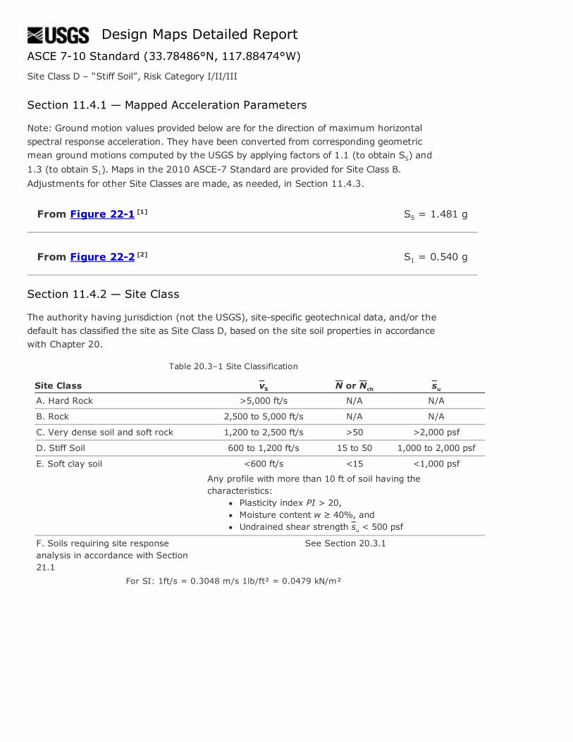
From Figure 221 [1]
From Figure 222 [2]
Design Maps Detailed ReportASCE 710 Standard (33.78486°N, 117.88474°W)
Site Class D – “Stiff Soil”, Risk Category I/II/III
Section 11.4.1 — Mapped Acceleration Parameters
Note: Ground motion values provided below are for the direction of maximum horizontalspectral response acceleration. They have been converted from corresponding geometricmean ground motions computed by the USGS by applying factors of 1.1 (to obtain SS) and1.3 (to obtain S1). Maps in the 2010 ASCE7 Standard are provided for Site Class B.Adjustments for other Site Classes are made, as needed, in Section 11.4.3.
SS = 1.481 g
S1 = 0.540 g
Section 11.4.2 — Site Class
The authority having jurisdiction (not the USGS), sitespecific geotechnical data, and/or thedefault has classified the site as Site Class D, based on the site soil properties in accordancewith Chapter 20.
Table 20.3–1 Site Classification
Site Class vS N or Nch suA. Hard Rock >5,000 ft/s N/A N/A
B. Rock 2,500 to 5,000 ft/s N/A N/A
C. Very dense soil and soft rock 1,200 to 2,500 ft/s >50 >2,000 psf
D. Stiff Soil 600 to 1,200 ft/s 15 to 50 1,000 to 2,000 psf
E. Soft clay soil <600 ft/s <15 <1,000 psf
Any profile with more than 10 ft of soil having thecharacteristics:
Plasticity index PI > 20,Moisture content w ≥ 40%, andUndrained shear strength su < 500 psf
F. Soils requiring site responseanalysis in accordance with Section21.1
See Section 20.3.1
For SI: 1ft/s = 0.3048 m/s 1lb/ft² = 0.0479 kN/m²
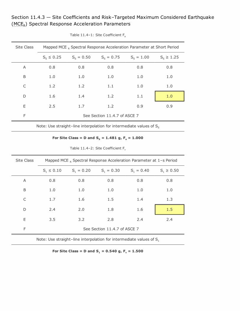
Section 11.4.3 — Site Coefficients and Risk–Targeted Maximum Considered Earthquake(MCER) Spectral Response Acceleration Parameters
Table 11.4–1: Site Coefficient Fa
Site Class Mapped MCE R Spectral Response Acceleration Parameter at Short Period
SS ≤ 0.25 SS = 0.50 SS = 0.75 SS = 1.00 SS ≥ 1.25
A 0.8 0.8 0.8 0.8 0.8
B 1.0 1.0 1.0 1.0 1.0
C 1.2 1.2 1.1 1.0 1.0
D 1.6 1.4 1.2 1.1 1.0
E 2.5 1.7 1.2 0.9 0.9
F See Section 11.4.7 of ASCE 7
Note: Use straight–line interpolation for intermediate values of SS
For Site Class = D and SS = 1.481 g, Fa = 1.000
Table 11.4–2: Site Coefficient Fv
Site Class Mapped MCE R Spectral Response Acceleration Parameter at 1–s Period
S1 ≤ 0.10 S1 = 0.20 S1 = 0.30 S1 = 0.40 S1 ≥ 0.50
A 0.8 0.8 0.8 0.8 0.8
B 1.0 1.0 1.0 1.0 1.0
C 1.7 1.6 1.5 1.4 1.3
D 2.4 2.0 1.8 1.6 1.5
E 3.5 3.2 2.8 2.4 2.4
F See Section 11.4.7 of ASCE 7
Note: Use straight–line interpolation for intermediate values of S1
For Site Class = D and S1 = 0.540 g, Fv = 1.500
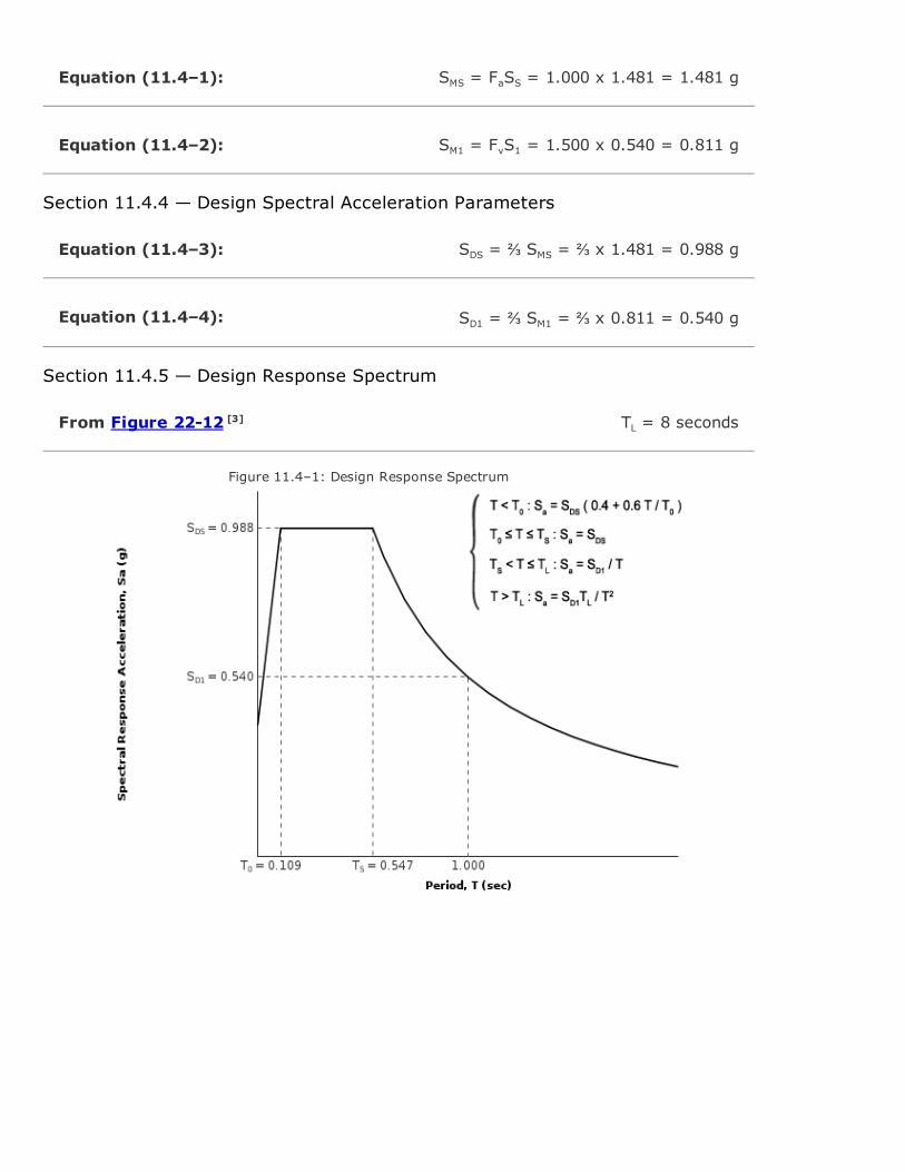
Equation (11.4–1):
Equation (11.4–2):
Equation (11.4–3):
Equation (11.4–4):
From Figure 2212 [3]
SMS = FaSS = 1.000 x 1.481 = 1.481 g
SM1 = FvS1 = 1.500 x 0.540 = 0.811 g
Section 11.4.4 — Design Spectral Acceleration Parameters
SDS = ⅔ SMS = ⅔ x 1.481 = 0.988 g
SD1 = ⅔ SM1 = ⅔ x 0.811 = 0.540 g
Section 11.4.5 — Design Response Spectrum
TL = 8 seconds
Figure 11.4–1: Design Response Spectrum
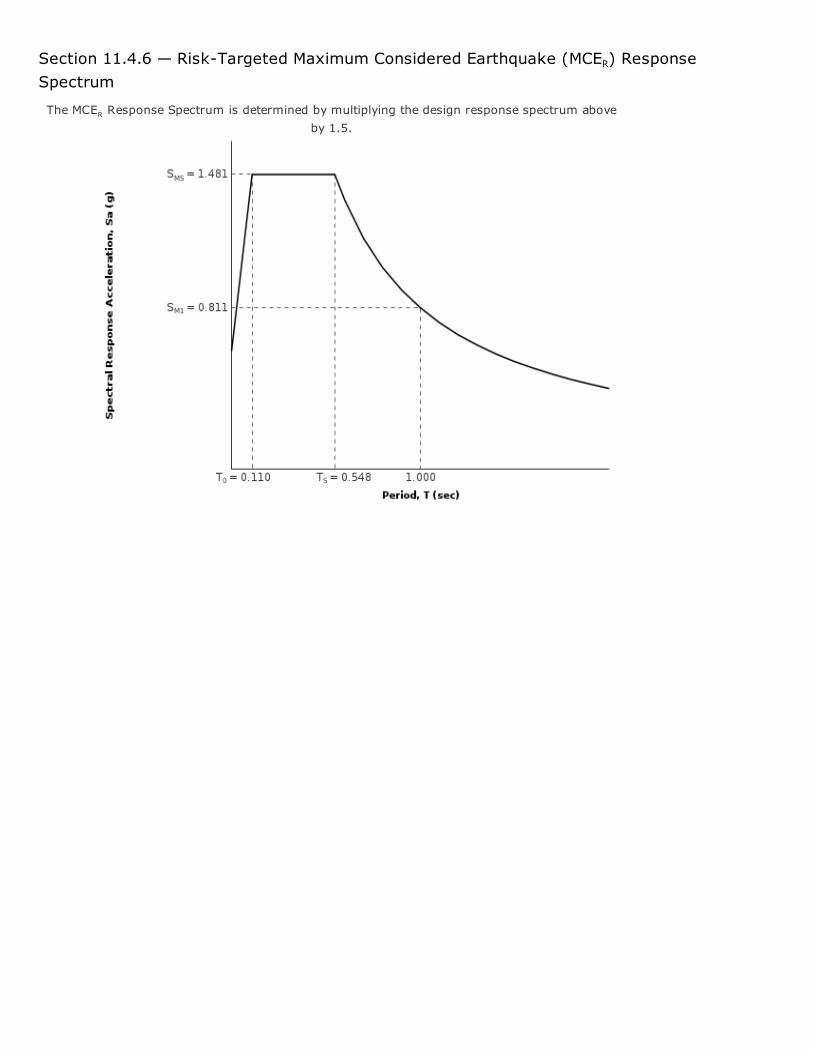
Section 11.4.6 — RiskTargeted Maximum Considered Earthquake (MCER) ResponseSpectrum
The MCER Response Spectrum is determined by multiplying the design response spectrum aboveby 1.5.
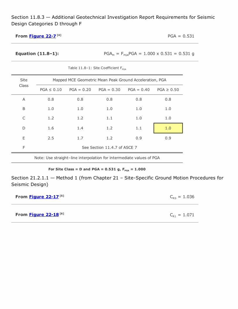
From Figure 227 [4]
Equation (11.8–1):
From Figure 2217 [5]
From Figure 2218 [6]
Section 11.8.3 — Additional Geotechnical Investigation Report Requirements for SeismicDesign Categories D through F
PGA = 0.531
PGAM = FPGAPGA = 1.000 x 0.531 = 0.531 g
Table 11.8–1: Site Coefficient FPGA
SiteClass
Mapped MCE Geometric Mean Peak Ground Acceleration, PGA
PGA ≤ 0.10 PGA = 0.20 PGA = 0.30 PGA = 0.40 PGA ≥ 0.50
A 0.8 0.8 0.8 0.8 0.8
B 1.0 1.0 1.0 1.0 1.0
C 1.2 1.2 1.1 1.0 1.0
D 1.6 1.4 1.2 1.1 1.0
E 2.5 1.7 1.2 0.9 0.9
F See Section 11.4.7 of ASCE 7
Note: Use straight–line interpolation for intermediate values of PGA
For Site Class = D and PGA = 0.531 g, FPGA = 1.000
Section 21.2.1.1 — Method 1 (from Chapter 21 – SiteSpecific Ground Motion Procedures forSeismic Design)
CRS = 1.036
CR1 = 1.071
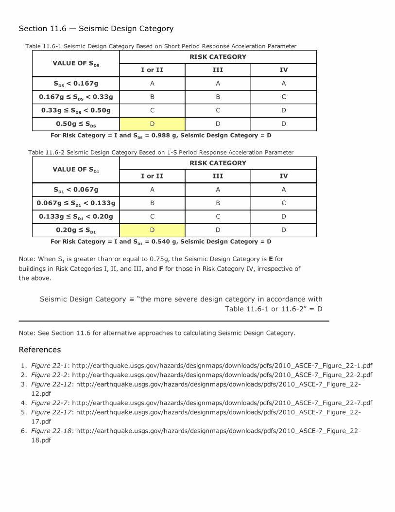
Section 11.6 — Seismic Design Category
Table 11.61 Seismic Design Category Based on Short Period Response Acceleration Parameter
VALUE OF SDSRISK CATEGORY
I or II III IV
SDS < 0.167g A A A
0.167g ≤ SDS < 0.33g B B C
0.33g ≤ SDS < 0.50g C C D
0.50g ≤ SDS D D D
For Risk Category = I and SDS = 0.988 g, Seismic Design Category = D
Table 11.62 Seismic Design Category Based on 1S Period Response Acceleration Parameter
VALUE OF SD1RISK CATEGORY
I or II III IV
SD1 < 0.067g A A A
0.067g ≤ SD1 < 0.133g B B C
0.133g ≤ SD1 < 0.20g C C D
0.20g ≤ SD1 D D D
For Risk Category = I and SD1 = 0.540 g, Seismic Design Category = D
Note: When S1 is greater than or equal to 0.75g, the Seismic Design Category is E forbuildings in Risk Categories I, II, and III, and F for those in Risk Category IV, irrespective ofthe above.
Seismic Design Category ≡ “the more severe design category in accordance withTable 11.61 or 11.62” = D
Note: See Section 11.6 for alternative approaches to calculating Seismic Design Category.
References
1. Figure 221: http://earthquake.usgs.gov/hazards/designmaps/downloads/pdfs/2010_ASCE7_Figure_221.pdf2. Figure 222: http://earthquake.usgs.gov/hazards/designmaps/downloads/pdfs/2010_ASCE7_Figure_222.pdf3. Figure 2212: http://earthquake.usgs.gov/hazards/designmaps/downloads/pdfs/2010_ASCE7_Figure_22
12.pdf4. Figure 227: http://earthquake.usgs.gov/hazards/designmaps/downloads/pdfs/2010_ASCE7_Figure_227.pdf5. Figure 2217: http://earthquake.usgs.gov/hazards/designmaps/downloads/pdfs/2010_ASCE7_Figure_22
17.pdf6. Figure 2218: http://earthquake.usgs.gov/hazards/designmaps/downloads/pdfs/2010_ASCE7_Figure_22
18.pdf
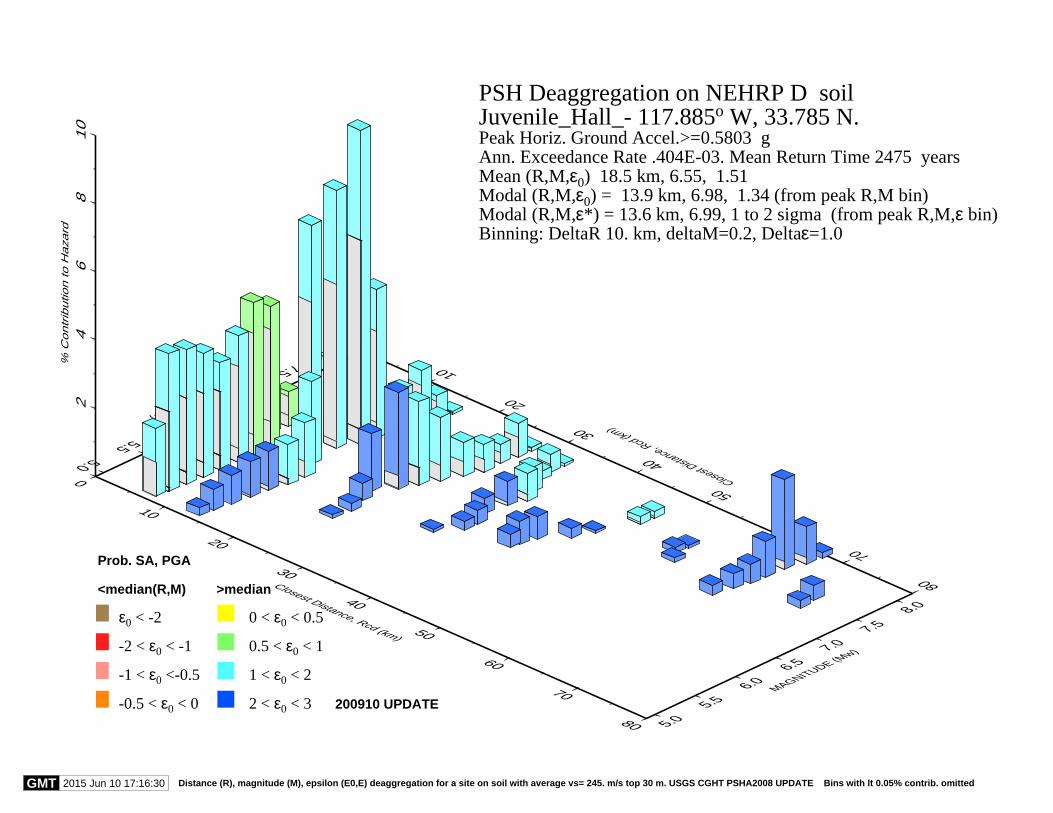
0
10
20
30
40
50
60
70
80
Closest Distance, Rcd (km)0
10
20
30
40
50
60
70
80
Closest Distance, Rcd (km)
5.0
5.5
6.0
6.5
7.0
7.5
8.0
MAGNITUDE (Mw)
5.0
5.5
6.0
6.5
7.0
7.5
8.0
MAGNITUDE (Mw)
24
68
10
% C
ontr
ibutio
n to H
aza
rd
PSH Deaggregation on NEHRP D soilJuvenile_Hall_- 117.885o W, 33.785 N.Peak Horiz. Ground Accel.>=0.5803 gAnn. Exceedance Rate .404E-03. Mean Return Time 2475 yearsMean (R,M,ε0) 18.5 km, 6.55, 1.51Modal (R,M,ε0) = 13.9 km, 6.98, 1.34 (from peak R,M bin)Modal (R,M,ε*) = 13.6 km, 6.99, 1 to 2 sigma (from peak R,M,ε bin)Binning: DeltaR 10. km, deltaM=0.2, Deltaε=1.0
200910 UPDATE
ε0 < -2
-2 < ε0 < -1
-1 < ε0 <-0.5
-0.5 < ε0 < 0
0 < ε0 < 0.5
0.5 < ε0 < 1
1 < ε0 < 2
2 < ε0 < 3
Prob. SA, PGA
<median(R,M) >median
GMT 2015 Jun 10 17:16:30 Distance (R), magnitude (M), epsilon (E0,E) deaggregation for a site on soil with average vs= 245. m/s top 30 m. USGS CGHT PSHA2008 UPDATE Bins with lt 0.05% contrib. omitted
APPENDIX E LIQUEFACTION ANALYSIS
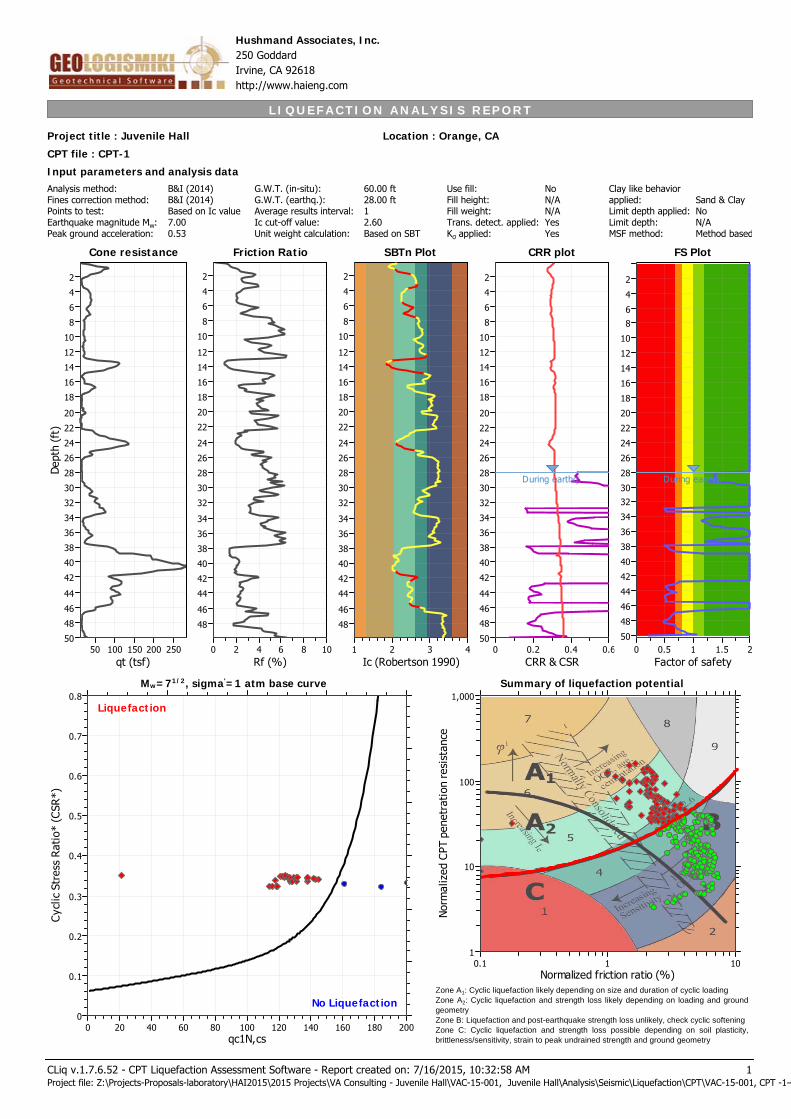
L I Q U E F A C T I O N A N A L Y S I S R E P O R T
Input parameters and analysis dataAnalysis method:Fines correction method:Points to test:Earthquake magnitude Mw:Peak ground acceleration:
B&I (2014)B&I (2014)Based on Ic value7.000.53
G.W.T. (in-situ):G.W.T. (earthq.):Average results interval:Ic cut-off value:Unit weight calculation:
Project title : Juvenile Hall Location : Orange, CA
Hushmand Associates, Inc.250 GoddardIrvine, CA 92618http://www.haieng.com
CPT file : CPT-1
60.00 ft28.00 ft12.60Based on SBT
Use fill:Fill height:Fill weight:Trans. detect. applied:Kσ applied:
NoN/AN/AYesYes
Clay like behaviorapplied:Limit depth applied:Limit depth:MSF method:
Sand & ClayNoN/AMethod based
Cone resistance
qt (tsf)25020015010050
Dep
th (
ft)
50
48
46
44
42
40
38
36
34
32
30
28
26
24
22
20
18
16
14
12
10
8
6
4
2
Cone resistance SBTn Plot
Ic (Robertson 1990)4321
48
46
44
42
40
38
36
34
32
30
28
26
24
22
20
18
16
14
12
10
8
6
4
2
SBTn Plot CRR plot
CRR & CSR0.60.40.20
50
48
46
44
42
40
38
36
34
32
30
28
26
24
22
20
18
16
14
12
10
8
6
4
2
CRR plot
During earthq.
qc1N,cs200180160140120100806040200
Cyc
lic S
tres
s R
atio
* (C
SR*)
0.8
0.7
0.6
0.5
0.4
0.3
0.2
0.1
0
Liquefaction
No Liquefaction
Normalized friction ratio (%)0.1 1 10
Nor
mal
ized
CPT
pen
etra
tion
res
ista
nce
1
10
100
1,000
Friction Ratio
Rf (%)1086420
48
46
44
42
40
38
36
34
32
30
28
26
24
22
20
18
16
14
12
10
8
6
4
2
Friction Ratio
Mw=71/2, sigma'=1 atm base curve Summary of liquefaction potential
FS Plot
Factor of safety21.510.50
50
48
46
44
42
40
38
36
34
3230
28
26
24
22
20
18
16
14
12
10
86
4
2
FS Plot
During earthq.
Zone A1: Cyclic liquefaction likely depending on size and duration of cyclic loading
Zone A2: Cyclic liquefaction and strength loss likely depending on loading and ground
geometry
Zone B: Liquefaction and post-earthquake strength loss unlikely, check cyclic softening
Zone C: Cyclic liquefaction and strength loss possible depending on soil plasticity,
brittleness/sensitivity, strain to peak undrained strength and ground geometry
CLiq v.1.7.6.52 - CPT Liquefaction Assessment Software - Report created on: 7/16/2015, 10:32:58 AMProject file: Z:\Projects-Proposals-laboratory\HAI2015\2015 Projects\VA Consulting - Juvenile Hall\VAC-15-001, Juvenile Hall\Analysis\Seismic\Liquefaction\CPT\VAC-15-001, CPT -1-4
1
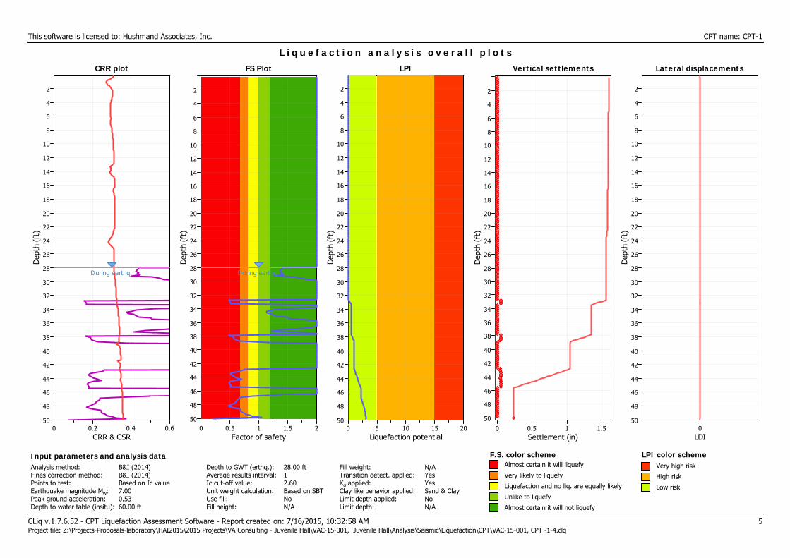
This software is licensed to: Hushmand Associates, Inc. CPT name: CPT-1
CRR plot
CRR & CSR0.60.40.20
Dep
th (
ft)
50
48
46
44
42
40
38
36
34
32
30
28
26
24
22
20
18
16
14
12
10
8
6
4
2
CRR plot
During earthq.
L i q u e f a c t i o n a n a l y s i s o v e r a l l p l o t s
FS Plot
Factor of safety21.510.50
Dep
th (
ft)
50
48
46
44
42
40
38
36
34
32
30
28
26
24
22
20
18
16
14
12
10
8
6
4
2
FS Plot
During earthq.
LPI
Liquefaction potential20151050
Dep
th (
ft)
50
48
46
44
42
40
38
36
34
32
30
28
26
24
22
20
18
16
14
12
10
8
6
4
2
LPI Vertical settlements
Settlement (in)1.510.50
Dep
th (
ft)
50
48
46
44
42
40
38
36
34
32
30
28
26
24
22
20
18
16
14
12
10
8
6
4
2
Vertical settlements Lateral displacements
LDI0
Dep
th (
ft)
50
48
46
44
42
40
38
36
34
32
30
28
26
24
22
20
18
16
14
12
10
8
6
4
2
Lateral displacements
CLiq v.1.7.6.52 - CPT Liquefaction Assessment Software - Report created on: 7/16/2015, 10:32:58 AM 5Project file: Z:\Projects-Proposals-laboratory\HAI2015\2015 Projects\VA Consulting - Juvenile Hall\VAC-15-001, Juvenile Hall\Analysis\Seismic\Liquefaction\CPT\VAC-15-001, CPT -1-4.clq
Input parameters and analysis dataAnalysis method:Fines correction method:Points to test:Earthquake magnitude Mw:Peak ground acceleration:Depth to water table (insitu):
B&I (2014)B&I (2014)Based on Ic value7.000.5360.00 ft
Depth to GWT (erthq.):Average results interval:Ic cut-off value:Unit weight calculation:Use fill:Fill height:
28.00 ft12.60Based on SBTNoN/A
Fill weight:Transition detect. applied:Kσ applied:Clay like behavior applied:Limit depth applied:Limit depth:
N/AYesYesSand & ClayNoN/A
F.S. color scheme LPI color schemeAlmost certain it will liquefy
Very likely to liquefy
Liquefaction and no liq. are equally likely
Unlike to liquefy
Almost certain it will not liquefy
Very high risk
High risk
Low risk

L I Q U E F A C T I O N A N A L Y S I S R E P O R T
Input parameters and analysis dataAnalysis method:Fines correction method:Points to test:Earthquake magnitude Mw:Peak ground acceleration:
B&I (2014)B&I (2014)Based on Ic value7.000.53
G.W.T. (in-situ):G.W.T. (earthq.):Average results interval:Ic cut-off value:Unit weight calculation:
Project title : Juvenile Hall Location : Orange, CA
Hushmand Associates, Inc.250 GoddardIrvine, CA 92618http://www.haieng.com
CPT file : CPT-2
60.00 ft28.00 ft12.60Based on SBT
Use fill:Fill height:Fill weight:Trans. detect. applied:Kσ applied:
NoN/AN/AYesYes
Clay like behaviorapplied:Limit depth applied:Limit depth:MSF method:
Sand & ClayNoN/AMethod based
Cone resistance
qt (tsf)400300200100
Dep
th (
ft)
50
48
46
44
42
40
38
36
34
32
30
28
26
24
22
20
18
16
14
12
10
8
6
4
2
Cone resistance SBTn Plot
Ic (Robertson 1990)4321
48
46
44
42
40
38
36
34
32
30
28
26
24
22
20
18
16
14
12
10
8
6
4
2
SBTn Plot CRR plot
CRR & CSR0.60.40.20
50
48
46
44
42
40
38
36
34
32
30
28
26
24
22
20
18
16
14
12
10
8
6
4
2
CRR plot
During earthq.
qc1N,cs200180160140120100806040200
Cyc
lic S
tres
s R
atio
* (C
SR*)
0.8
0.7
0.6
0.5
0.4
0.3
0.2
0.1
0
Liquefaction
No Liquefaction
Normalized friction ratio (%)0.1 1 10
Nor
mal
ized
CPT
pen
etra
tion
res
ista
nce
1
10
100
1,000
Friction Ratio
Rf (%)1086420
48
46
44
42
40
38
36
34
32
30
28
26
24
22
20
18
16
14
12
10
8
6
4
2
Friction Ratio
Mw=71/2, sigma'=1 atm base curve Summary of liquefaction potential
FS Plot
Factor of safety21.510.50
50
48
46
44
42
40
38
36
34
3230
28
26
24
22
20
18
16
14
12
10
86
4
2
FS Plot
During earthq.
Zone A1: Cyclic liquefaction likely depending on size and duration of cyclic loading
Zone A2: Cyclic liquefaction and strength loss likely depending on loading and ground
geometry
Zone B: Liquefaction and post-earthquake strength loss unlikely, check cyclic softening
Zone C: Cyclic liquefaction and strength loss possible depending on soil plasticity,
brittleness/sensitivity, strain to peak undrained strength and ground geometry
CLiq v.1.7.6.52 - CPT Liquefaction Assessment Software - Report created on: 7/16/2015, 10:32:59 AMProject file: Z:\Projects-Proposals-laboratory\HAI2015\2015 Projects\VA Consulting - Juvenile Hall\VAC-15-001, Juvenile Hall\Analysis\Seismic\Liquefaction\CPT\VAC-15-001, CPT -1-4
52
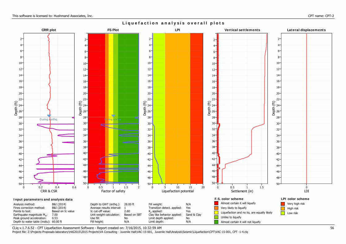
This software is licensed to: Hushmand Associates, Inc. CPT name: CPT-2
CRR plot
CRR & CSR0.60.40.20
Dep
th (
ft)
50
48
46
44
42
40
38
36
34
32
30
28
26
24
22
20
18
16
14
12
10
8
6
4
2
CRR plot
During earthq.
L i q u e f a c t i o n a n a l y s i s o v e r a l l p l o t s
FS Plot
Factor of safety21.510.50
Dep
th (
ft)
50
48
46
44
42
40
38
36
34
32
30
28
26
24
22
20
18
16
14
12
10
8
6
4
2
FS Plot
During earthq.
LPI
Liquefaction potential20151050
Dep
th (
ft)
50
48
46
44
42
40
38
36
34
32
30
28
26
24
22
20
18
16
14
12
10
8
6
4
2
LPI Vertical settlements
Settlement (in)1.510.50
Dep
th (
ft)
50
48
46
44
42
40
38
36
34
32
30
28
26
24
22
20
18
16
14
12
10
8
6
4
2
Vertical settlements Lateral displacements
LDI0
Dep
th (
ft)
50
48
46
44
42
40
38
36
34
32
30
28
26
24
22
20
18
16
14
12
10
8
6
4
2
Lateral displacements
CLiq v.1.7.6.52 - CPT Liquefaction Assessment Software - Report created on: 7/16/2015, 10:32:59 AM 56Project file: Z:\Projects-Proposals-laboratory\HAI2015\2015 Projects\VA Consulting - Juvenile Hall\VAC-15-001, Juvenile Hall\Analysis\Seismic\Liquefaction\CPT\VAC-15-001, CPT -1-4.clq
Input parameters and analysis dataAnalysis method:Fines correction method:Points to test:Earthquake magnitude Mw:Peak ground acceleration:Depth to water table (insitu):
B&I (2014)B&I (2014)Based on Ic value7.000.5360.00 ft
Depth to GWT (erthq.):Average results interval:Ic cut-off value:Unit weight calculation:Use fill:Fill height:
28.00 ft12.60Based on SBTNoN/A
Fill weight:Transition detect. applied:Kσ applied:Clay like behavior applied:Limit depth applied:Limit depth:
N/AYesYesSand & ClayNoN/A
F.S. color scheme LPI color schemeAlmost certain it will liquefy
Very likely to liquefy
Liquefaction and no liq. are equally likely
Unlike to liquefy
Almost certain it will not liquefy
Very high risk
High risk
Low risk
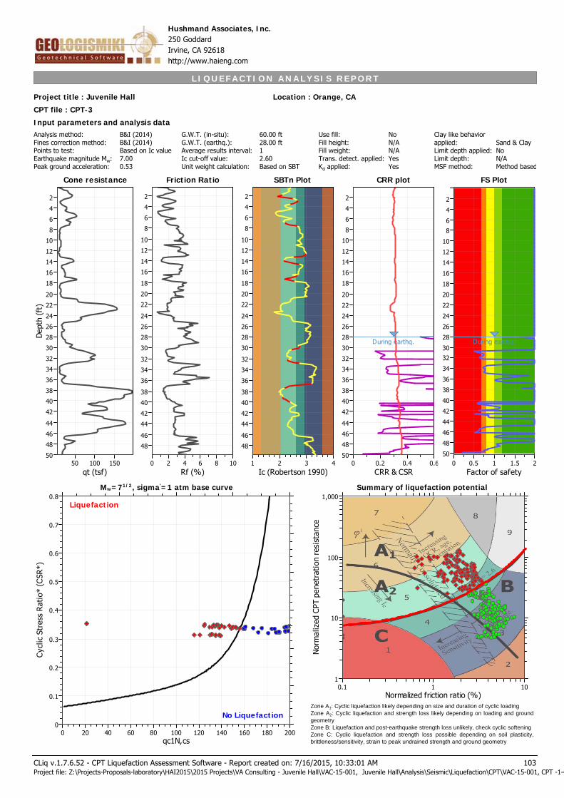
L I Q U E F A C T I O N A N A L Y S I S R E P O R T
Input parameters and analysis dataAnalysis method:Fines correction method:Points to test:Earthquake magnitude Mw:Peak ground acceleration:
B&I (2014)B&I (2014)Based on Ic value7.000.53
G.W.T. (in-situ):G.W.T. (earthq.):Average results interval:Ic cut-off value:Unit weight calculation:
Project title : Juvenile Hall Location : Orange, CA
Hushmand Associates, Inc.250 GoddardIrvine, CA 92618http://www.haieng.com
CPT file : CPT-3
60.00 ft28.00 ft12.60Based on SBT
Use fill:Fill height:Fill weight:Trans. detect. applied:Kσ applied:
NoN/AN/AYesYes
Clay like behaviorapplied:Limit depth applied:Limit depth:MSF method:
Sand & ClayNoN/AMethod based
Cone resistance
qt (tsf)15010050
Dep
th (
ft)
50
48
46
44
42
40
38
36
34
32
30
28
26
24
22
20
18
16
14
12
10
8
6
4
2
Cone resistance SBTn Plot
Ic (Robertson 1990)4321
48
46
44
42
40
38
36
34
32
30
28
26
24
22
20
18
16
14
12
10
8
6
4
2
SBTn Plot CRR plot
CRR & CSR0.60.40.20
50
48
46
44
42
40
38
36
34
32
30
28
26
24
22
20
18
16
14
12
10
8
6
4
2
CRR plot
During earthq.
qc1N,cs200180160140120100806040200
Cyc
lic S
tres
s R
atio
* (C
SR*)
0.8
0.7
0.6
0.5
0.4
0.3
0.2
0.1
0
Liquefaction
No Liquefaction
Normalized friction ratio (%)0.1 1 10
Nor
mal
ized
CPT
pen
etra
tion
res
ista
nce
1
10
100
1,000
Friction Ratio
Rf (%)1086420
48
46
44
42
40
38
36
34
32
30
28
26
24
22
20
18
16
14
12
10
8
6
4
2
Friction Ratio
Mw=71/2, sigma'=1 atm base curve Summary of liquefaction potential
FS Plot
Factor of safety21.510.50
50
48
46
44
42
40
38
36
34
3230
28
26
24
22
20
18
16
14
12
10
86
4
2
FS Plot
During earthq.
Zone A1: Cyclic liquefaction likely depending on size and duration of cyclic loading
Zone A2: Cyclic liquefaction and strength loss likely depending on loading and ground
geometry
Zone B: Liquefaction and post-earthquake strength loss unlikely, check cyclic softening
Zone C: Cyclic liquefaction and strength loss possible depending on soil plasticity,
brittleness/sensitivity, strain to peak undrained strength and ground geometry
CLiq v.1.7.6.52 - CPT Liquefaction Assessment Software - Report created on: 7/16/2015, 10:33:01 AMProject file: Z:\Projects-Proposals-laboratory\HAI2015\2015 Projects\VA Consulting - Juvenile Hall\VAC-15-001, Juvenile Hall\Analysis\Seismic\Liquefaction\CPT\VAC-15-001, CPT -1-4
103
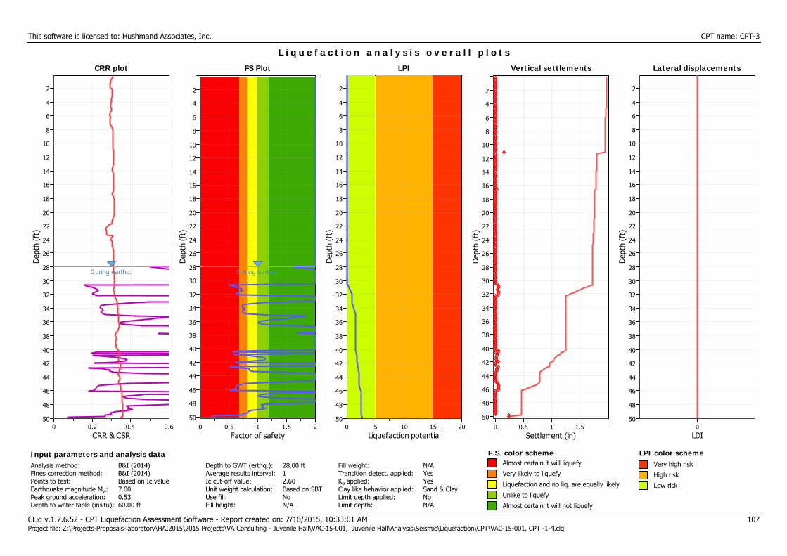
This software is licensed to: Hushmand Associates, Inc. CPT name: CPT-3
CRR plot
CRR & CSR0.60.40.20
Dep
th (
ft)
50
48
46
44
42
40
38
36
34
32
30
28
26
24
22
20
18
16
14
12
10
8
6
4
2
CRR plot
During earthq.
L i q u e f a c t i o n a n a l y s i s o v e r a l l p l o t s
FS Plot
Factor of safety21.510.50
Dep
th (
ft)
50
48
46
44
42
40
38
36
34
32
30
28
26
24
22
20
18
16
14
12
10
8
6
4
2
FS Plot
During earthq.
LPI
Liquefaction potential20151050
Dep
th (
ft)
50
48
46
44
42
40
38
36
34
32
30
28
26
24
22
20
18
16
14
12
10
8
6
4
2
LPI Vertical settlements
Settlement (in)1.510.50
Dep
th (
ft)
50
48
46
44
42
40
38
36
34
32
30
28
26
24
22
20
18
16
14
12
10
8
6
4
2
Vertical settlements Lateral displacements
LDI0
Dep
th (
ft)
50
48
46
44
42
40
38
36
34
32
30
28
26
24
22
20
18
16
14
12
10
8
6
4
2
Lateral displacements
CLiq v.1.7.6.52 - CPT Liquefaction Assessment Software - Report created on: 7/16/2015, 10:33:01 AM 107Project file: Z:\Projects-Proposals-laboratory\HAI2015\2015 Projects\VA Consulting - Juvenile Hall\VAC-15-001, Juvenile Hall\Analysis\Seismic\Liquefaction\CPT\VAC-15-001, CPT -1-4.clq
Input parameters and analysis dataAnalysis method:Fines correction method:Points to test:Earthquake magnitude Mw:Peak ground acceleration:Depth to water table (insitu):
B&I (2014)B&I (2014)Based on Ic value7.000.5360.00 ft
Depth to GWT (erthq.):Average results interval:Ic cut-off value:Unit weight calculation:Use fill:Fill height:
28.00 ft12.60Based on SBTNoN/A
Fill weight:Transition detect. applied:Kσ applied:Clay like behavior applied:Limit depth applied:Limit depth:
N/AYesYesSand & ClayNoN/A
F.S. color scheme LPI color schemeAlmost certain it will liquefy
Very likely to liquefy
Liquefaction and no liq. are equally likely
Unlike to liquefy
Almost certain it will not liquefy
Very high risk
High risk
Low risk
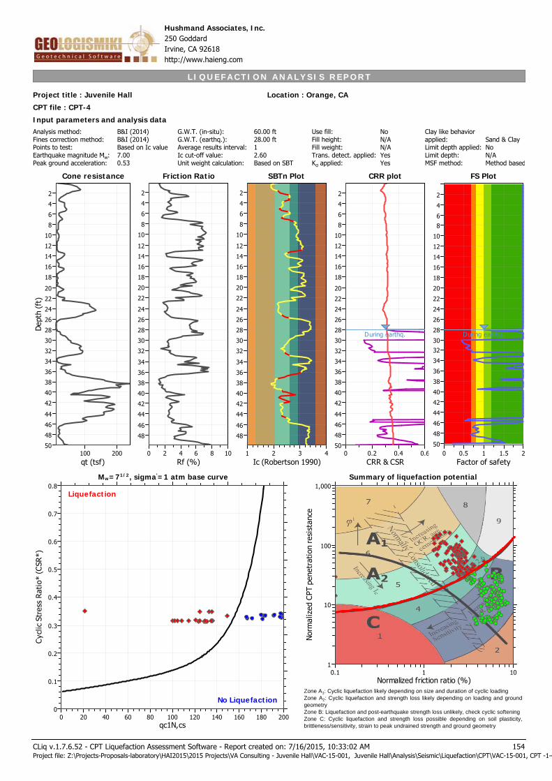
L I Q U E F A C T I O N A N A L Y S I S R E P O R T
Input parameters and analysis dataAnalysis method:Fines correction method:Points to test:Earthquake magnitude Mw:Peak ground acceleration:
B&I (2014)B&I (2014)Based on Ic value7.000.53
G.W.T. (in-situ):G.W.T. (earthq.):Average results interval:Ic cut-off value:Unit weight calculation:
Project title : Juvenile Hall Location : Orange, CA
Hushmand Associates, Inc.250 GoddardIrvine, CA 92618http://www.haieng.com
CPT file : CPT-4
60.00 ft28.00 ft12.60Based on SBT
Use fill:Fill height:Fill weight:Trans. detect. applied:Kσ applied:
NoN/AN/AYesYes
Clay like behaviorapplied:Limit depth applied:Limit depth:MSF method:
Sand & ClayNoN/AMethod based
Cone resistance
qt (tsf)200100
Dep
th (
ft)
50
48
46
44
42
40
38
36
34
32
30
28
26
24
22
20
18
16
14
12
10
8
6
4
2
Cone resistance SBTn Plot
Ic (Robertson 1990)4321
48
46
44
42
40
38
36
34
32
30
28
26
24
22
20
18
16
14
12
10
8
6
4
2
SBTn Plot CRR plot
CRR & CSR0.60.40.20
50
48
46
44
42
40
38
36
34
32
30
28
26
24
22
20
18
16
14
12
10
8
6
4
2
CRR plot
During earthq.
qc1N,cs200180160140120100806040200
Cyc
lic S
tres
s R
atio
* (C
SR*)
0.8
0.7
0.6
0.5
0.4
0.3
0.2
0.1
0
Liquefaction
No Liquefaction
Normalized friction ratio (%)0.1 1 10
Nor
mal
ized
CPT
pen
etra
tion
res
ista
nce
1
10
100
1,000
Friction Ratio
Rf (%)1086420
48
46
44
42
40
38
36
34
32
30
28
26
24
22
20
18
16
14
12
10
8
6
4
2
Friction Ratio
Mw=71/2, sigma'=1 atm base curve Summary of liquefaction potential
FS Plot
Factor of safety21.510.50
50
48
46
44
42
40
38
36
34
3230
28
26
24
22
20
18
16
14
12
10
86
4
2
FS Plot
During earthq.
Zone A1: Cyclic liquefaction likely depending on size and duration of cyclic loading
Zone A2: Cyclic liquefaction and strength loss likely depending on loading and ground
geometry
Zone B: Liquefaction and post-earthquake strength loss unlikely, check cyclic softening
Zone C: Cyclic liquefaction and strength loss possible depending on soil plasticity,
brittleness/sensitivity, strain to peak undrained strength and ground geometry
CLiq v.1.7.6.52 - CPT Liquefaction Assessment Software - Report created on: 7/16/2015, 10:33:02 AMProject file: Z:\Projects-Proposals-laboratory\HAI2015\2015 Projects\VA Consulting - Juvenile Hall\VAC-15-001, Juvenile Hall\Analysis\Seismic\Liquefaction\CPT\VAC-15-001, CPT -1-4
154
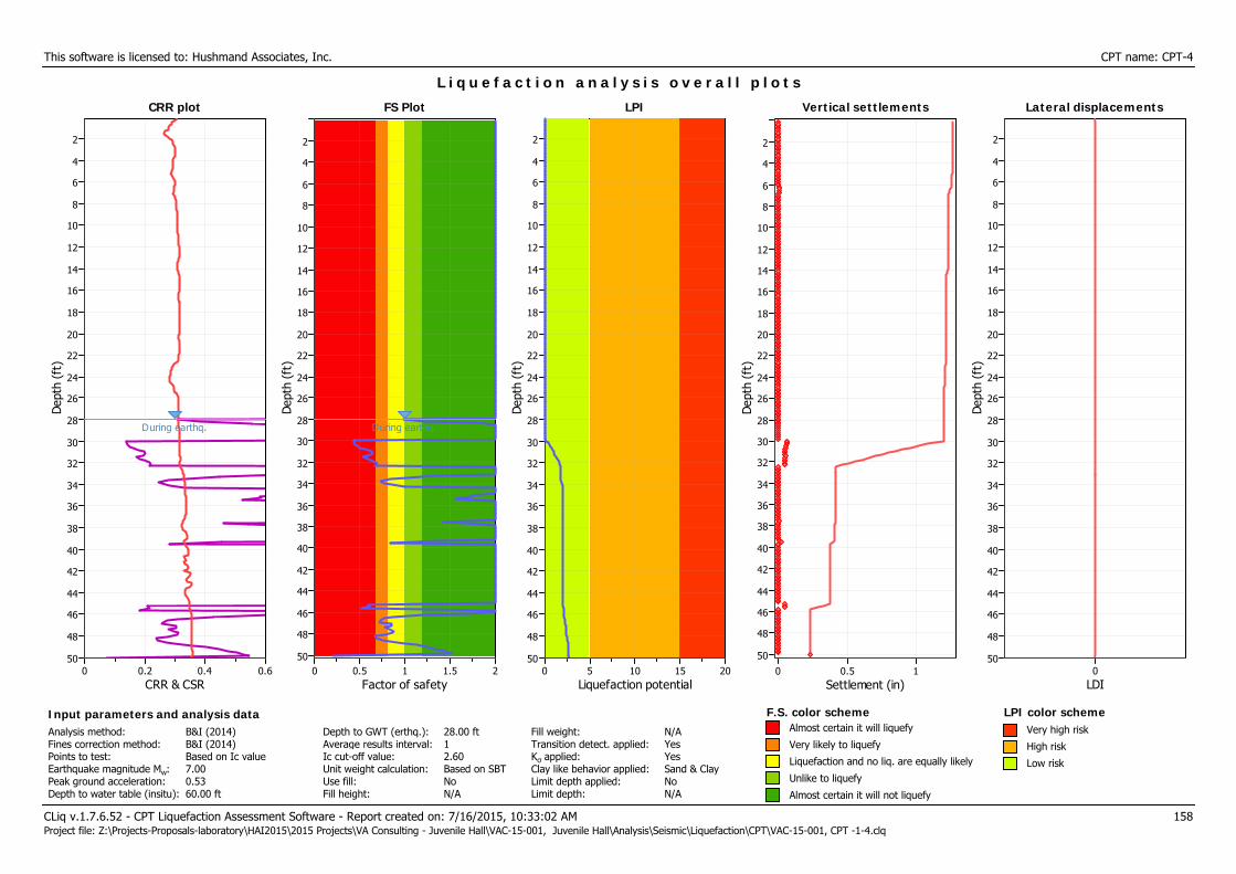
This software is licensed to: Hushmand Associates, Inc. CPT name: CPT-4
CRR plot
CRR & CSR0.60.40.20
Dep
th (
ft)
50
48
46
44
42
40
38
36
34
32
30
28
26
24
22
20
18
16
14
12
10
8
6
4
2
CRR plot
During earthq.
L i q u e f a c t i o n a n a l y s i s o v e r a l l p l o t s
FS Plot
Factor of safety21.510.50
Dep
th (
ft)
50
48
46
44
42
40
38
36
34
32
30
28
26
24
22
20
18
16
14
12
10
8
6
4
2
FS Plot
During earthq.
LPI
Liquefaction potential20151050
Dep
th (
ft)
50
48
46
44
42
40
38
36
34
32
30
28
26
24
22
20
18
16
14
12
10
8
6
4
2
LPI Vertical settlements
Settlement (in)10.50
Dep
th (
ft)
50
48
46
44
42
40
38
36
34
32
30
28
26
24
22
20
18
16
14
12
10
8
6
4
2
Vertical settlements Lateral displacements
LDI0
Dep
th (
ft)
50
48
46
44
42
40
38
36
34
32
30
28
26
24
22
20
18
16
14
12
10
8
6
4
2
Lateral displacements
CLiq v.1.7.6.52 - CPT Liquefaction Assessment Software - Report created on: 7/16/2015, 10:33:02 AM 158Project file: Z:\Projects-Proposals-laboratory\HAI2015\2015 Projects\VA Consulting - Juvenile Hall\VAC-15-001, Juvenile Hall\Analysis\Seismic\Liquefaction\CPT\VAC-15-001, CPT -1-4.clq
Input parameters and analysis dataAnalysis method:Fines correction method:Points to test:Earthquake magnitude Mw:Peak ground acceleration:Depth to water table (insitu):
B&I (2014)B&I (2014)Based on Ic value7.000.5360.00 ft
Depth to GWT (erthq.):Average results interval:Ic cut-off value:Unit weight calculation:Use fill:Fill height:
28.00 ft12.60Based on SBTNoN/A
Fill weight:Transition detect. applied:Kσ applied:Clay like behavior applied:Limit depth applied:Limit depth:
N/AYesYesSand & ClayNoN/A
F.S. color scheme LPI color schemeAlmost certain it will liquefy
Very likely to liquefy
Liquefaction and no liq. are equally likely
Unlike to liquefy
Almost certain it will not liquefy
Very high risk
High risk
Low risk

L I Q U E F A C T I O N A N A L Y S I S R E P O R T
Input parameters and analysis dataAnalysis method:Fines correction method:Points to test:Earthquake magnitude Mw:Peak ground acceleration:
B&I (2014)B&I (2014)Based on Ic value7.000.53
G.W.T. (in-situ):G.W.T. (earthq.):Average results interval:Ic cut-off value:Unit weight calculation:
Project title : Juvenile Hall Location : Orange, CA
Hushmand Associates, Inc.250 GoddardIrvine, CA 92618http://www.haieng.com
CPT file : CPT-5
60.00 ft35.00 ft12.60Based on SBT
Use fill:Fill height:Fill weight:Trans. detect. applied:Kσ applied:
NoN/AN/AYesYes
Clay like behaviorapplied:Limit depth applied:Limit depth:MSF method:
Sand & ClayNoN/AMethod based
Cone resistance
qt (tsf)25020015010050
Dep
th (
ft)
50
48
46
44
42
40
38
36
34
32
30
28
26
24
22
20
18
16
14
12
10
8
6
4
2
Cone resistance SBTn Plot
Ic (Robertson 1990)4321
48
46
44
42
40
38
36
34
32
30
28
26
24
22
20
18
16
14
12
10
8
6
4
2
SBTn Plot CRR plot
CRR & CSR0.60.40.20
50
48
46
44
42
40
38
36
34
32
30
28
26
24
22
20
18
16
14
12
10
8
6
4
2
CRR plot
During earthq.
qc1N,cs200180160140120100806040200
Cyc
lic S
tres
s R
atio
* (C
SR*)
0.8
0.7
0.6
0.5
0.4
0.3
0.2
0.1
0
Liquefaction
No Liquefaction
Normalized friction ratio (%)0.1 1 10
Nor
mal
ized
CPT
pen
etra
tion
res
ista
nce
1
10
100
1,000
Friction Ratio
Rf (%)1086420
48
46
44
42
40
38
36
34
32
30
28
26
24
22
20
18
16
14
12
10
8
6
4
2
Friction Ratio
Mw=71/2, sigma'=1 atm base curve Summary of liquefaction potential
FS Plot
Factor of safety21.510.50
50
48
46
44
42
40
38
36
34
3230
28
26
24
22
20
18
16
14
12
10
86
4
2
FS Plot
During earthq.
Zone A1: Cyclic liquefaction likely depending on size and duration of cyclic loading
Zone A2: Cyclic liquefaction and strength loss likely depending on loading and ground
geometry
Zone B: Liquefaction and post-earthquake strength loss unlikely, check cyclic softening
Zone C: Cyclic liquefaction and strength loss possible depending on soil plasticity,
brittleness/sensitivity, strain to peak undrained strength and ground geometry
CLiq v.1.7.6.52 - CPT Liquefaction Assessment Software - Report created on: 7/16/2015, 10:44:06 AMProject file: Z:\Projects-Proposals-laboratory\HAI2015\2015 Projects\VA Consulting - Juvenile Hall\VAC-15-001, Juvenile Hall\Analysis\Seismic\Liquefaction\CPT\VAC-15-001, CPT -5-8
1
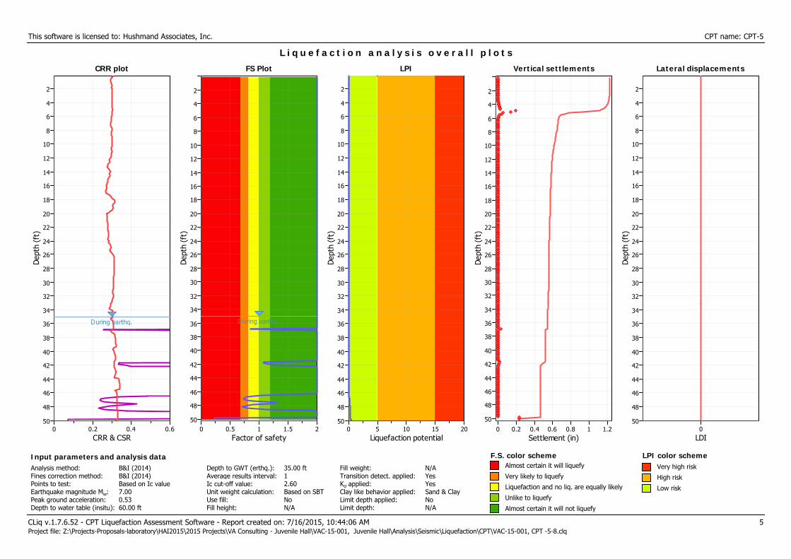
This software is licensed to: Hushmand Associates, Inc. CPT name: CPT-5
CRR plot
CRR & CSR0.60.40.20
Dep
th (
ft)
50
48
46
44
42
40
38
36
34
32
30
28
26
24
22
20
18
16
14
12
10
8
6
4
2
CRR plot
During earthq.
L i q u e f a c t i o n a n a l y s i s o v e r a l l p l o t s
FS Plot
Factor of safety21.510.50
Dep
th (
ft)
50
48
46
44
42
40
38
36
34
32
30
28
26
24
22
20
18
16
14
12
10
8
6
4
2
FS Plot
During earthq.
LPI
Liquefaction potential20151050
Dep
th (
ft)
50
48
46
44
42
40
38
36
34
32
30
28
26
24
22
20
18
16
14
12
10
8
6
4
2
LPI Vertical settlements
Settlement (in)1.210.80.60.40.20
Dep
th (
ft)
50
48
46
44
42
40
38
36
34
32
30
28
26
24
22
20
18
16
14
12
10
8
6
4
2
Vertical settlements Lateral displacements
LDI0
Dep
th (
ft)
50
48
46
44
42
40
38
36
34
32
30
28
26
24
22
20
18
16
14
12
10
8
6
4
2
Lateral displacements
CLiq v.1.7.6.52 - CPT Liquefaction Assessment Software - Report created on: 7/16/2015, 10:44:06 AM 5Project file: Z:\Projects-Proposals-laboratory\HAI2015\2015 Projects\VA Consulting - Juvenile Hall\VAC-15-001, Juvenile Hall\Analysis\Seismic\Liquefaction\CPT\VAC-15-001, CPT -5-8.clq
Input parameters and analysis dataAnalysis method:Fines correction method:Points to test:Earthquake magnitude Mw:Peak ground acceleration:Depth to water table (insitu):
B&I (2014)B&I (2014)Based on Ic value7.000.5360.00 ft
Depth to GWT (erthq.):Average results interval:Ic cut-off value:Unit weight calculation:Use fill:Fill height:
35.00 ft12.60Based on SBTNoN/A
Fill weight:Transition detect. applied:Kσ applied:Clay like behavior applied:Limit depth applied:Limit depth:
N/AYesYesSand & ClayNoN/A
F.S. color scheme LPI color schemeAlmost certain it will liquefy
Very likely to liquefy
Liquefaction and no liq. are equally likely
Unlike to liquefy
Almost certain it will not liquefy
Very high risk
High risk
Low risk
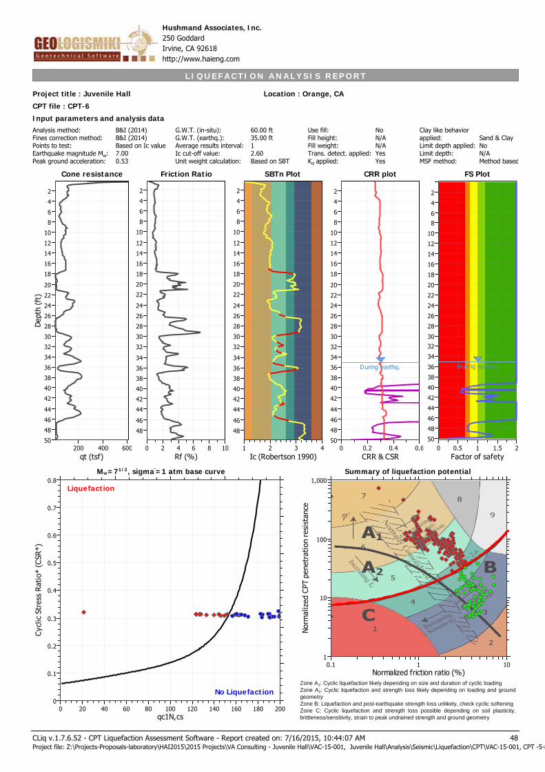
L I Q U E F A C T I O N A N A L Y S I S R E P O R T
Input parameters and analysis dataAnalysis method:Fines correction method:Points to test:Earthquake magnitude Mw:Peak ground acceleration:
B&I (2014)B&I (2014)Based on Ic value7.000.53
G.W.T. (in-situ):G.W.T. (earthq.):Average results interval:Ic cut-off value:Unit weight calculation:
Project title : Juvenile Hall Location : Orange, CA
Hushmand Associates, Inc.250 GoddardIrvine, CA 92618http://www.haieng.com
CPT file : CPT-6
60.00 ft35.00 ft12.60Based on SBT
Use fill:Fill height:Fill weight:Trans. detect. applied:Kσ applied:
NoN/AN/AYesYes
Clay like behaviorapplied:Limit depth applied:Limit depth:MSF method:
Sand & ClayNoN/AMethod based
Cone resistance
qt (tsf)600400200
Dep
th (
ft)
50
48
46
44
42
40
38
36
34
32
30
28
26
24
22
20
18
16
14
12
10
8
6
4
2
Cone resistance SBTn Plot
Ic (Robertson 1990)4321
48
46
44
42
40
38
36
34
32
30
28
26
24
22
20
18
16
14
12
10
8
6
4
2
SBTn Plot CRR plot
CRR & CSR0.60.40.20
50
48
46
44
42
40
38
36
34
32
30
28
26
24
22
20
18
16
14
12
10
8
6
4
2
CRR plot
During earthq.
qc1N,cs200180160140120100806040200
Cyc
lic S
tres
s R
atio
* (C
SR*)
0.8
0.7
0.6
0.5
0.4
0.3
0.2
0.1
0
Liquefaction
No Liquefaction
Normalized friction ratio (%)0.1 1 10
Nor
mal
ized
CPT
pen
etra
tion
res
ista
nce
1
10
100
1,000
Friction Ratio
Rf (%)1086420
48
46
44
42
40
38
36
34
32
30
28
26
24
22
20
18
16
14
12
10
8
6
4
2
Friction Ratio
Mw=71/2, sigma'=1 atm base curve Summary of liquefaction potential
FS Plot
Factor of safety21.510.50
50
48
46
44
42
40
38
36
34
3230
28
26
24
22
20
18
16
14
12
10
86
4
2
FS Plot
During earthq.
Zone A1: Cyclic liquefaction likely depending on size and duration of cyclic loading
Zone A2: Cyclic liquefaction and strength loss likely depending on loading and ground
geometry
Zone B: Liquefaction and post-earthquake strength loss unlikely, check cyclic softening
Zone C: Cyclic liquefaction and strength loss possible depending on soil plasticity,
brittleness/sensitivity, strain to peak undrained strength and ground geometry
CLiq v.1.7.6.52 - CPT Liquefaction Assessment Software - Report created on: 7/16/2015, 10:44:07 AMProject file: Z:\Projects-Proposals-laboratory\HAI2015\2015 Projects\VA Consulting - Juvenile Hall\VAC-15-001, Juvenile Hall\Analysis\Seismic\Liquefaction\CPT\VAC-15-001, CPT -5-8
48

This software is licensed to: Hushmand Associates, Inc. CPT name: CPT-6
CRR plot
CRR & CSR0.60.40.20
Dep
th (
ft)
50
48
46
44
42
40
38
36
34
32
30
28
26
24
22
20
18
16
14
12
10
8
6
4
2
CRR plot
During earthq.
L i q u e f a c t i o n a n a l y s i s o v e r a l l p l o t s
FS Plot
Factor of safety21.510.50
Dep
th (
ft)
50
48
46
44
42
40
38
36
34
32
30
28
26
24
22
20
18
16
14
12
10
8
6
4
2
FS Plot
During earthq.
LPI
Liquefaction potential20151050
Dep
th (
ft)
50
48
46
44
42
40
38
36
34
32
30
28
26
24
22
20
18
16
14
12
10
8
6
4
2
LPI Vertical settlements
Settlement (in)0.80.60.40.20
Dep
th (
ft)
50
48
46
44
42
40
38
36
34
32
30
28
26
24
22
20
18
16
14
12
10
8
6
4
2
Vertical settlements Lateral displacements
LDI0
Dep
th (
ft)
50
48
46
44
42
40
38
36
34
32
30
28
26
24
22
20
18
16
14
12
10
8
6
4
2
Lateral displacements
CLiq v.1.7.6.52 - CPT Liquefaction Assessment Software - Report created on: 7/16/2015, 10:44:07 AM 52Project file: Z:\Projects-Proposals-laboratory\HAI2015\2015 Projects\VA Consulting - Juvenile Hall\VAC-15-001, Juvenile Hall\Analysis\Seismic\Liquefaction\CPT\VAC-15-001, CPT -5-8.clq
Input parameters and analysis dataAnalysis method:Fines correction method:Points to test:Earthquake magnitude Mw:Peak ground acceleration:Depth to water table (insitu):
B&I (2014)B&I (2014)Based on Ic value7.000.5360.00 ft
Depth to GWT (erthq.):Average results interval:Ic cut-off value:Unit weight calculation:Use fill:Fill height:
35.00 ft12.60Based on SBTNoN/A
Fill weight:Transition detect. applied:Kσ applied:Clay like behavior applied:Limit depth applied:Limit depth:
N/AYesYesSand & ClayNoN/A
F.S. color scheme LPI color schemeAlmost certain it will liquefy
Very likely to liquefy
Liquefaction and no liq. are equally likely
Unlike to liquefy
Almost certain it will not liquefy
Very high risk
High risk
Low risk

L I Q U E F A C T I O N A N A L Y S I S R E P O R T
Input parameters and analysis dataAnalysis method:Fines correction method:Points to test:Earthquake magnitude Mw:Peak ground acceleration:
B&I (2014)B&I (2014)Based on Ic value7.000.53
G.W.T. (in-situ):G.W.T. (earthq.):Average results interval:Ic cut-off value:Unit weight calculation:
Project title : Juvenile Hall Location : Orange, CA
Hushmand Associates, Inc.250 GoddardIrvine, CA 92618http://www.haieng.com
CPT file : CPT-7
60.00 ft35.00 ft12.60Based on SBT
Use fill:Fill height:Fill weight:Trans. detect. applied:Kσ applied:
NoN/AN/AYesYes
Clay like behaviorapplied:Limit depth applied:Limit depth:MSF method:
Sand & ClayNoN/AMethod based
Cone resistance
qt (tsf)300200100
Dep
th (
ft)
50
48
46
44
42
40
38
36
34
32
30
28
26
24
22
20
18
16
14
12
10
8
6
4
2
Cone resistance SBTn Plot
Ic (Robertson 1990)4321
48
46
44
42
40
38
36
34
32
30
28
26
24
22
20
18
16
14
12
10
8
6
4
2
SBTn Plot CRR plot
CRR & CSR0.60.40.20
50
48
46
44
42
40
38
36
34
32
30
28
26
24
22
20
18
16
14
12
10
8
6
4
2
CRR plot
During earthq.
qc1N,cs200180160140120100806040200
Cyc
lic S
tres
s R
atio
* (C
SR*)
0.8
0.7
0.6
0.5
0.4
0.3
0.2
0.1
0
Liquefaction
No Liquefaction
Normalized friction ratio (%)0.1 1 10
Nor
mal
ized
CPT
pen
etra
tion
res
ista
nce
1
10
100
1,000
Friction Ratio
Rf (%)1086420
48
46
44
42
40
38
36
34
32
30
28
26
24
22
20
18
16
14
12
10
8
6
4
2
Friction Ratio
Mw=71/2, sigma'=1 atm base curve Summary of liquefaction potential
FS Plot
Factor of safety21.510.50
50
48
46
44
42
40
38
36
34
3230
28
26
24
22
20
18
16
14
12
10
86
4
2
FS Plot
During earthq.
Zone A1: Cyclic liquefaction likely depending on size and duration of cyclic loading
Zone A2: Cyclic liquefaction and strength loss likely depending on loading and ground
geometry
Zone B: Liquefaction and post-earthquake strength loss unlikely, check cyclic softening
Zone C: Cyclic liquefaction and strength loss possible depending on soil plasticity,
brittleness/sensitivity, strain to peak undrained strength and ground geometry
CLiq v.1.7.6.52 - CPT Liquefaction Assessment Software - Report created on: 7/16/2015, 10:44:08 AMProject file: Z:\Projects-Proposals-laboratory\HAI2015\2015 Projects\VA Consulting - Juvenile Hall\VAC-15-001, Juvenile Hall\Analysis\Seismic\Liquefaction\CPT\VAC-15-001, CPT -5-8
95
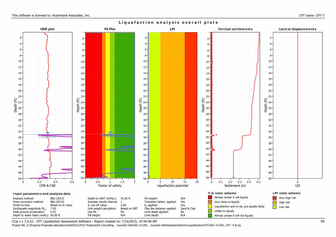
This software is licensed to: Hushmand Associates, Inc. CPT name: CPT-7
CRR plot
CRR & CSR0.60.40.20
Dep
th (
ft)
50
48
46
44
42
40
38
36
34
32
30
28
26
24
22
20
18
16
14
12
10
8
6
4
2
CRR plot
During earthq.
L i q u e f a c t i o n a n a l y s i s o v e r a l l p l o t s
FS Plot
Factor of safety21.510.50
Dep
th (
ft)
50
48
46
44
42
40
38
36
34
32
30
28
26
24
22
20
18
16
14
12
10
8
6
4
2
FS Plot
During earthq.
LPI
Liquefaction potential20151050
Dep
th (
ft)
50
48
46
44
42
40
38
36
34
32
30
28
26
24
22
20
18
16
14
12
10
8
6
4
2
LPI Vertical settlements
Settlement (in)0.50.40.30.20.10
Dep
th (
ft)
50
48
46
44
42
40
38
36
34
32
30
28
26
24
22
20
18
16
14
12
10
8
6
4
2
Vertical settlements Lateral displacements
LDI0
Dep
th (
ft)
50
48
46
44
42
40
38
36
34
32
30
28
26
24
22
20
18
16
14
12
10
8
6
4
2
Lateral displacements
CLiq v.1.7.6.52 - CPT Liquefaction Assessment Software - Report created on: 7/16/2015, 10:44:08 AM 99Project file: Z:\Projects-Proposals-laboratory\HAI2015\2015 Projects\VA Consulting - Juvenile Hall\VAC-15-001, Juvenile Hall\Analysis\Seismic\Liquefaction\CPT\VAC-15-001, CPT -5-8.clq
Input parameters and analysis dataAnalysis method:Fines correction method:Points to test:Earthquake magnitude Mw:Peak ground acceleration:Depth to water table (insitu):
B&I (2014)B&I (2014)Based on Ic value7.000.5360.00 ft
Depth to GWT (erthq.):Average results interval:Ic cut-off value:Unit weight calculation:Use fill:Fill height:
35.00 ft12.60Based on SBTNoN/A
Fill weight:Transition detect. applied:Kσ applied:Clay like behavior applied:Limit depth applied:Limit depth:
N/AYesYesSand & ClayNoN/A
F.S. color scheme LPI color schemeAlmost certain it will liquefy
Very likely to liquefy
Liquefaction and no liq. are equally likely
Unlike to liquefy
Almost certain it will not liquefy
Very high risk
High risk
Low risk
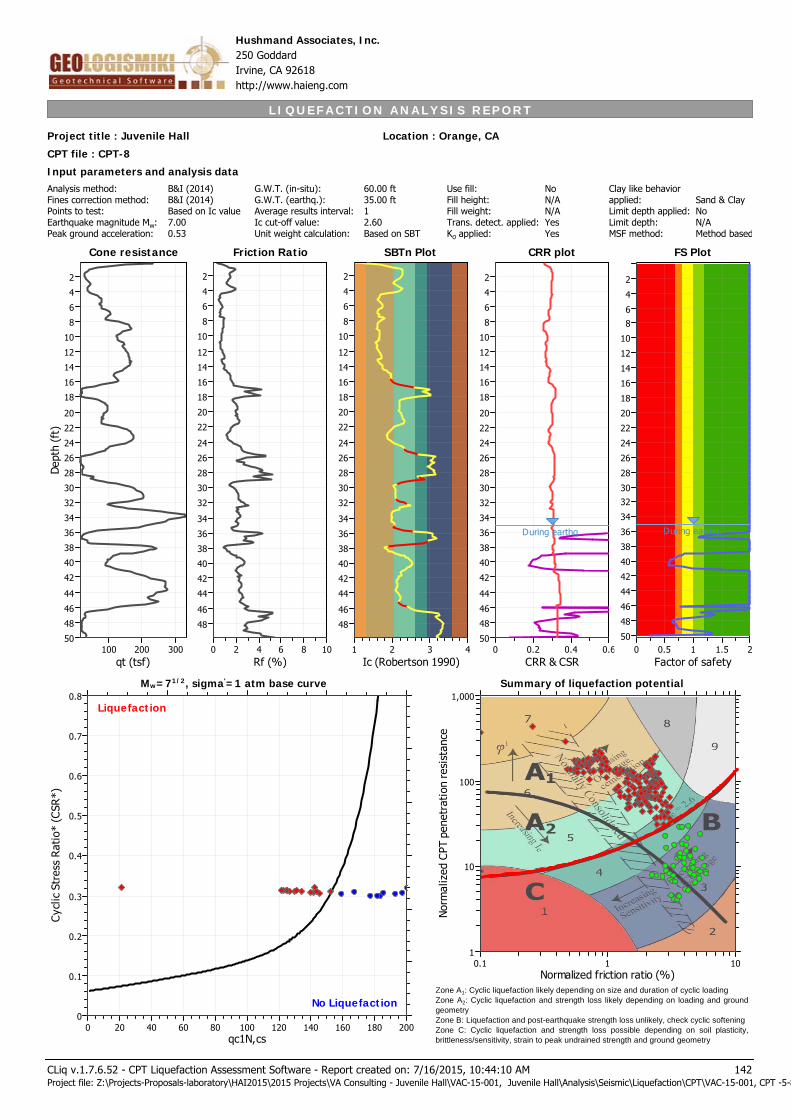
L I Q U E F A C T I O N A N A L Y S I S R E P O R T
Input parameters and analysis dataAnalysis method:Fines correction method:Points to test:Earthquake magnitude Mw:Peak ground acceleration:
B&I (2014)B&I (2014)Based on Ic value7.000.53
G.W.T. (in-situ):G.W.T. (earthq.):Average results interval:Ic cut-off value:Unit weight calculation:
Project title : Juvenile Hall Location : Orange, CA
Hushmand Associates, Inc.250 GoddardIrvine, CA 92618http://www.haieng.com
CPT file : CPT-8
60.00 ft35.00 ft12.60Based on SBT
Use fill:Fill height:Fill weight:Trans. detect. applied:Kσ applied:
NoN/AN/AYesYes
Clay like behaviorapplied:Limit depth applied:Limit depth:MSF method:
Sand & ClayNoN/AMethod based
Cone resistance
qt (tsf)300200100
Dep
th (
ft)
50
48
46
44
42
40
38
36
34
32
30
28
26
24
22
20
18
16
14
12
10
8
6
4
2
Cone resistance SBTn Plot
Ic (Robertson 1990)4321
48
46
44
42
40
38
36
34
32
30
28
26
24
22
20
18
16
14
12
10
8
6
4
2
SBTn Plot CRR plot
CRR & CSR0.60.40.20
50
48
46
44
42
40
38
36
34
32
30
28
26
24
22
20
18
16
14
12
10
8
6
4
2
CRR plot
During earthq.
qc1N,cs200180160140120100806040200
Cyc
lic S
tres
s R
atio
* (C
SR*)
0.8
0.7
0.6
0.5
0.4
0.3
0.2
0.1
0
Liquefaction
No Liquefaction
Normalized friction ratio (%)0.1 1 10
Nor
mal
ized
CPT
pen
etra
tion
res
ista
nce
1
10
100
1,000
Friction Ratio
Rf (%)1086420
48
46
44
42
40
38
36
34
32
30
28
26
24
22
20
18
16
14
12
10
8
6
4
2
Friction Ratio
Mw=71/2, sigma'=1 atm base curve Summary of liquefaction potential
FS Plot
Factor of safety21.510.50
50
48
46
44
42
40
38
36
34
3230
28
26
24
22
20
18
16
14
12
10
86
4
2
FS Plot
During earthq.
Zone A1: Cyclic liquefaction likely depending on size and duration of cyclic loading
Zone A2: Cyclic liquefaction and strength loss likely depending on loading and ground
geometry
Zone B: Liquefaction and post-earthquake strength loss unlikely, check cyclic softening
Zone C: Cyclic liquefaction and strength loss possible depending on soil plasticity,
brittleness/sensitivity, strain to peak undrained strength and ground geometry
CLiq v.1.7.6.52 - CPT Liquefaction Assessment Software - Report created on: 7/16/2015, 10:44:10 AMProject file: Z:\Projects-Proposals-laboratory\HAI2015\2015 Projects\VA Consulting - Juvenile Hall\VAC-15-001, Juvenile Hall\Analysis\Seismic\Liquefaction\CPT\VAC-15-001, CPT -5-8
142

This software is licensed to: Hushmand Associates, Inc. CPT name: CPT-8
CRR plot
CRR & CSR0.60.40.20
Dep
th (
ft)
50
48
46
44
42
40
38
36
34
32
30
28
26
24
22
20
18
16
14
12
10
8
6
4
2
CRR plot
During earthq.
L i q u e f a c t i o n a n a l y s i s o v e r a l l p l o t s
FS Plot
Factor of safety21.510.50
Dep
th (
ft)
50
48
46
44
42
40
38
36
34
32
30
28
26
24
22
20
18
16
14
12
10
8
6
4
2
FS Plot
During earthq.
LPI
Liquefaction potential20151050
Dep
th (
ft)
50
48
46
44
42
40
38
36
34
32
30
28
26
24
22
20
18
16
14
12
10
8
6
4
2
LPI Vertical settlements
Settlement (in)0.80.60.40.20
Dep
th (
ft)
50
48
46
44
42
40
38
36
34
32
30
28
26
24
22
20
18
16
14
12
10
8
6
4
2
Vertical settlements Lateral displacements
LDI0
Dep
th (
ft)
50
48
46
44
42
40
38
36
34
32
30
28
26
24
22
20
18
16
14
12
10
8
6
4
2
Lateral displacements
CLiq v.1.7.6.52 - CPT Liquefaction Assessment Software - Report created on: 7/16/2015, 10:44:10 AM 146Project file: Z:\Projects-Proposals-laboratory\HAI2015\2015 Projects\VA Consulting - Juvenile Hall\VAC-15-001, Juvenile Hall\Analysis\Seismic\Liquefaction\CPT\VAC-15-001, CPT -5-8.clq
Input parameters and analysis dataAnalysis method:Fines correction method:Points to test:Earthquake magnitude Mw:Peak ground acceleration:Depth to water table (insitu):
B&I (2014)B&I (2014)Based on Ic value7.000.5360.00 ft
Depth to GWT (erthq.):Average results interval:Ic cut-off value:Unit weight calculation:Use fill:Fill height:
35.00 ft12.60Based on SBTNoN/A
Fill weight:Transition detect. applied:Kσ applied:Clay like behavior applied:Limit depth applied:Limit depth:
N/AYesYesSand & ClayNoN/A
F.S. color scheme LPI color schemeAlmost certain it will liquefy
Very likely to liquefy
Liquefaction and no liq. are equally likely
Unlike to liquefy
Almost certain it will not liquefy
Very high risk
High risk
Low risk
APPENDIX F GEOGRID REINFORCED SUBGRADE
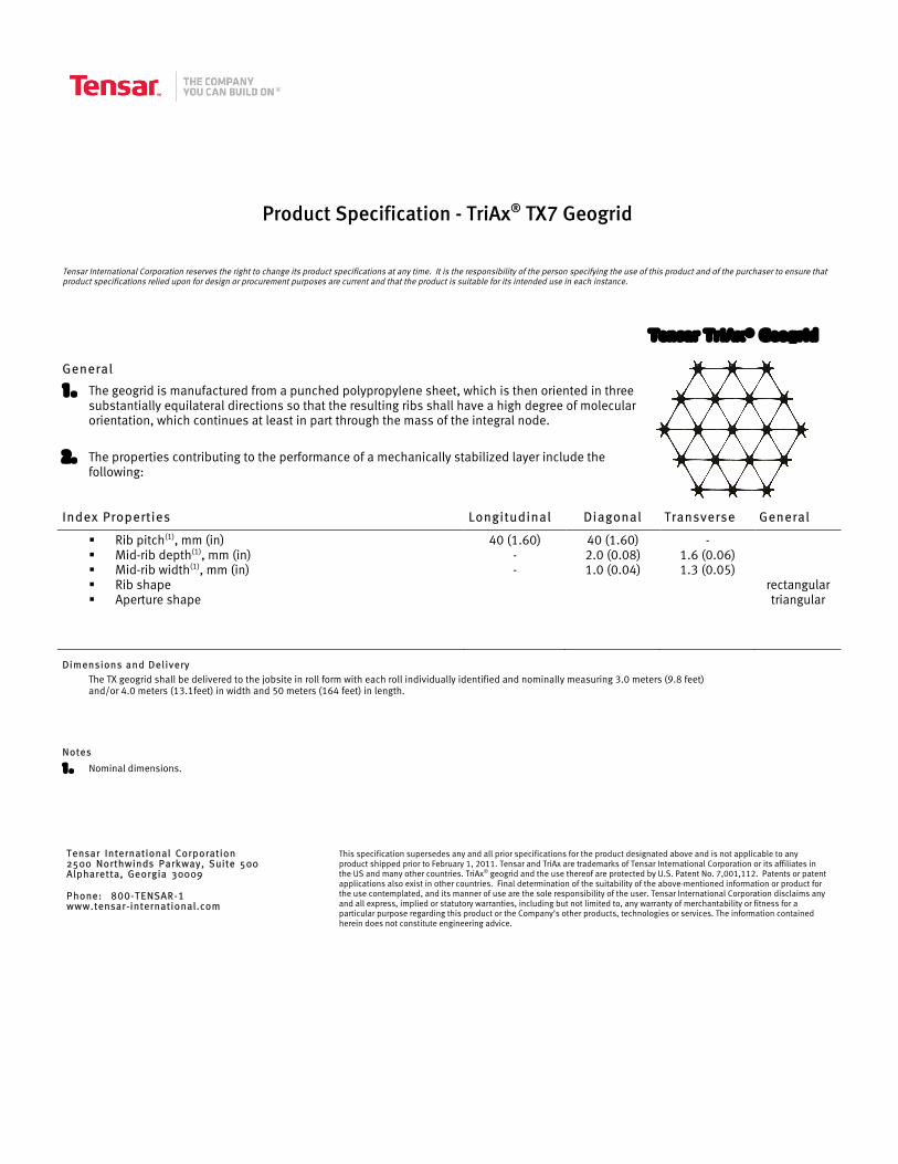
Product Specification - TriAx® TX7 Geogrid
Tensar International Corporation reserves the right to change its product specifications at any time. It is the responsibility of the person specifying the use of this product and of the purchaser to ensure that product specifications relied upon for design or procurement purposes are current and that the product is suitable for its intended use in each instance.
General
1. The geogrid is manufactured from a punched polypropylene sheet, which is then oriented in three substantially equilateral directions so that the resulting ribs shall have a high degree of molecular orientation, which continues at least in part through the mass of the integral node.
2. The properties contributing to the performance of a mechanically stabilized layer include the following:
Index Properties Longitudinal Diagonal Transverse General
Rib pitch(1), mm (in) Mid-rib depth(1), mm (in) Mid-rib width(1), mm (in) Rib shape Aperture shape
40 (1.60) - -
40 (1.60) 2.0 (0.08) 1.0 (0.04)
- 1.6 (0.06) 1.3 (0.05)
rectangular triangular
Dimensions and Delivery The TX geogrid shall be delivered to the jobsite in roll form with each roll individually identified and nominally measuring 3.0 meters (9.8 feet) and/or 4.0 meters (13.1feet) in width and 50 meters (164 feet) in length.
Notes
1. Nominal dimensions.
Tensar International Corporation 2500 Northwinds Parkway, Suite 500 Alpharetta, Georgia 30009 Phone: 800-TENSAR-1 www.tensar-international.com
This specification supersedes any and all prior specifications for the product designated above and is not applicable to any product shipped prior to February 1, 2011. Tensar and TriAx are trademarks of Tensar International Corporation or its affiliates in the US and many other countries. TriAx® geogrid and the use thereof are protected by U.S. Patent No. 7,001,112. Patents or patent applications also exist in other countries. Final determination of the suitability of the above-mentioned information or product for the use contemplated, and its manner of use are the sole responsibility of the user. Tensar International Corporation disclaims any and all express, implied or statutory warranties, including but not limited to, any warranty of merchantability or fitness for a particular purpose regarding this product or the Company’s other products, technologies or services. The information contained herein does not constitute engineering advice.
Tensar TriAx® Geogrid
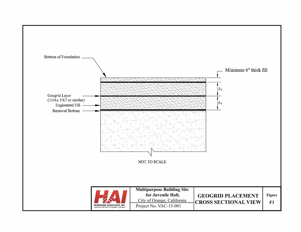
Project No. VAC-15-001
Multipurpose Building Sitefor Juvenile Hall,
City of Orange, CaliforniaFigureGEOGRID PLACEMENT
CROSS SECTIONAL VIEW F1
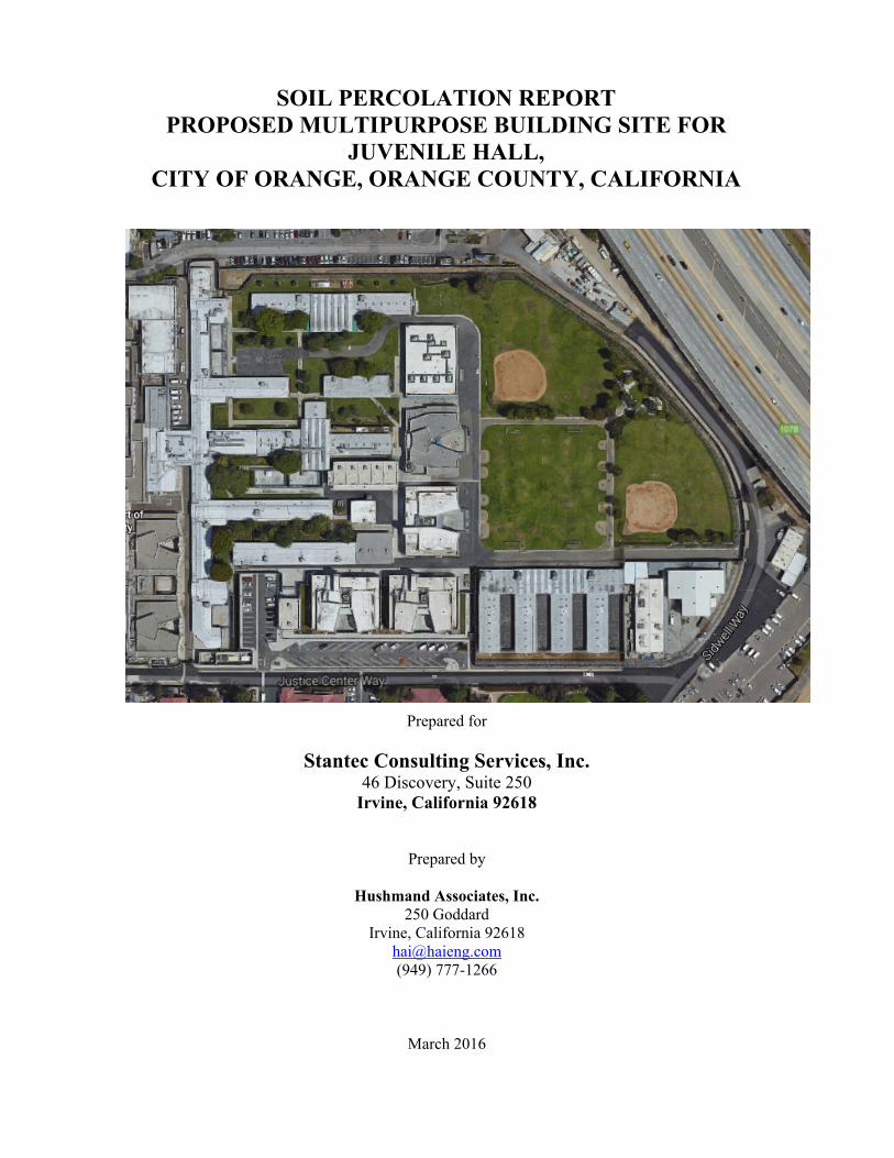
SOIL PERCOLATION REPORT PROPOSED MULTIPURPOSE BUILDING SITE FOR
JUVENILE HALL, CITY OF ORANGE, ORANGE COUNTY, CALIFORNIA
Prepared for
Stantec Consulting Services, Inc. 46 Discovery, Suite 250
Irvine, California 92618
Prepared by
Hushmand Associates, Inc. 250 Goddard
Irvine, California 92618 [email protected] (949) 777-1266
March 2016
Hushmand Associates, Inc. 250 Goddard Irvine, CA 92618
p. (949) 777‐1266 w. www.haieng.com e. [email protected]
March 14, 2016 Stantec Consulting Services Inc. 46 Discovery, Suite 250 Irvine, California 92618 Attn.: Mr. Thomas A. Broz, PE, SE, F. ASCE SUBJECT: SOIL PERCOLATION TEST REPORT
PROPOSED MULTIPURPOSE BUILDING SITE FOR JUVENILE HALL CITY OF ORANGE, CALIFORNIA HAI PROJECT NO. VAC-15-001
Dear Mr. Broz: Per your request, Hushmand Associates, Inc. (HAI) has completed two percolation tests at the project site for the proposed Multipurpose Building site for Juvenile Hall, located in the City of Orange, California. This report has been prepared in accordance with the scope of work outlined in HAI’s Proposal No. P16-0115 dated January 15, 2016. Project Description and Background
The project consists of constructing a 25,000 square feet (SF) Multi-Purpose Building (MRC) within the Orange County Juvenile Hall Campus (Figure 1). The MRC includes a visitation center, gymnasium, multipurpose rooms, treatment rooms, and support facilities. Two locations within the existing campus were considered for the proposed building site. The preferred location is on an existing baseball field (Preferred Site) in close proximity to the Santa Ana River. The alternate location is on the northwest corner of the campus (Alternate Site) on land that is currently occupied by four existing housing units (Buildings R, S, O, M, and Class Rooms 19 and 20). The Preferred Site will have a footprint of between 41,232 SF and 60,000 SF, while the Alternate Site will have a footprint of 80,500 SF. The purpose of this investigation is to measure the infiltration rates of subsoils in the Preferred Site location of the proposed Multipurpose Building. The locations of the percolation tests are shown in Figure 2. Subsurface Conditions
A soil boring was drilled at two locations on February 16, 2016 to evaluate the subsurface soil conditions within the planned depth. Based on the soil cuttings retreated from the soil borings, the subsurface soils at the test locations P-1 and P-2 consist of silt/sandy silt, silty sand and sandy to silty clays. Groundwater was not encountered during drilling. The boring logs are presented in Appendix A. Laboratory test results are included in Appendix B.
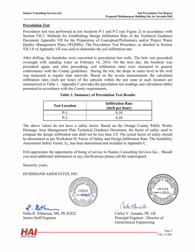
Stantec Consulting Services Inc. Soil Percolation Test Report Proposed Multipurpose Building Site for Juvenile Hall
Page 2
VAC-15-001
Percolation Test
Percolation test was performed at test locations P-1 and P-2 (see Figure 2) in accordance with Section VII.3: Methods for Establishing Design Infiltration Rate of the Technical Guidance Document Appendix VII for the Preparation of Conceptual/Preliminary and/or Project Water Quality Management Plans (WQMPs). The Percolation Test Procedure, as detailed in Section VII.3.8 of Appendix VII was used to determine the soil infiltration rate. After drilling, the boreholes were converted to percolation test wells. The hole was presoaked overnight with standing water on February 16, 2016. On the next day, the borehole was presoaked again, and after presoaking, soil infiltration rates were measured in general conformance with the County guidelines. During the test, the drops in water level in the well was measured at regular time intervals. Based on the in-situ measurement, the calculated infiltration rates (inch per hour) of the subsoils within the test zone at each location are summarized in Table 1. Appendix C provides the percolation test readings and calculation tables presented in accordance with the County requirements.
Table 1: Summary of Percolation Test Results The above values do not have a safety factor. Based on the Orange County Public Works Drainage Area Management Plan Technical Guidance Document, the factor of safety used to compute the design infiltration rate shall not be less than 2.0. The actual factor of safety should be determined as per Worksheet H: Factor of Safety and Design Infiltration Rate. The Suitability Assessment Safety Factor, SA, has been determined and included in Appendix C. HAI appreciates the opportunity of being of service to Stantec Consulting Services Inc., Should you need additional information or any clarifications please call the undersigned. Sincerely yours, HUSHMAND ASSOCIATES, INC.
Nitha R. Nitharsan, MS, PE 82422 Carlos V. Amante, PE, GE Senior Staff Engineer Principal Engineer / Director of
Geotechnical Engineering
Test Location Infiltration Rate (inch per hour)
P-1 0.10 P-2 0.28
Stantec Consulting Services Inc. Soil Percolation Test Report Proposed Multipurpose Building Site for Juvenile Hall
Page 3
VAC-15-001
Attachments:
Figures:
Figure 1 Site Vicinity Map Figure 2 Percolation Test Locations
Appendices:
Appendix A Logs of Exploratory Borings Appendix B Laboratory Test Results Appendix C Percolation Test Data Sheets

FIGURES
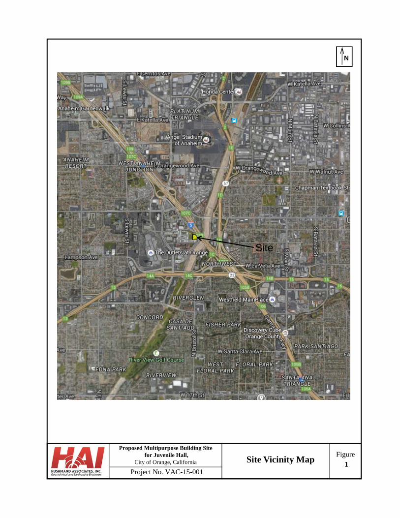
Project No. VAC-15-001
FigureProposed Multipurpose Building Site
for Juvenile Hall, City of Orange, California
N
Site Vicinity Map1
Site
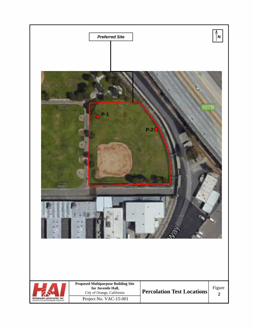
Project No. VAC-15-001
FigureProposed Multipurpose Building Site
for Juvenile Hall, City of Orange, California
NPreferred Site
Percolation Test Locations 2
P-2
P-1

APPENDIX A LOGS OF EXPLORATORY BORINGS
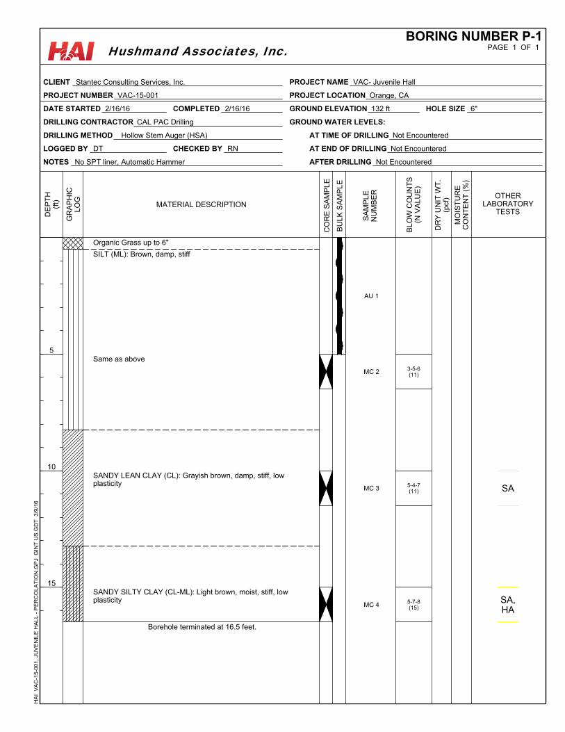
3-5-6(11)
5-4-7(11)
5-7-8(15)
Organic Grass up to 6"
SILT (ML): Brown, damp, stiff
Same as above
SANDY LEAN CLAY (CL): Grayish brown, damp, stiff, lowplasticity
SANDY SILTY CLAY (CL-ML): Light brown, moist, stiff, lowplasticity
Borehole terminated at 16.5 feet.
AU 1
MC 2
MC 3
MC 4
SA
SA,HA
NOTES No SPT liner, Automatic Hammer
GROUND ELEVATION 132 ft
LOGGED BY DT
DATE STARTED 2/16/16
DRILLING METHOD Hollow Stem Auger (HSA) AT TIME OF DRILLING Not Encountered
AT END OF DRILLING Not Encountered
AFTER DRILLING Not Encountered
HOLE SIZE 6"
DRILLING CONTRACTOR CAL PAC Drilling GROUND WATER LEVELS:
CHECKED BY RN
COMPLETED 2/16/16
CO
RE
SA
MP
LE
5
10
15
DE
PT
H(f
t)
GR
AP
HIC
LO
G OTHERLABORATORY
TESTS
SA
MP
LE
NU
MB
ER
MATERIAL DESCRIPTION
BU
LK
SA
MP
LE
BL
OW
CO
UN
TS
(N V
AL
UE
)
DR
Y U
NIT
WT
.(p
cf)
MO
IST
UR
EC
ON
TE
NT
(%
)
PAGE 1 OF 1BORING NUMBER P-1
CLIENT Stantec Consulting Services, Inc.
PROJECT NUMBER VAC-15-001
PROJECT NAME VAC- Juvenile Hall
PROJECT LOCATION Orange, CA
HA
I V
AC
-15-
001,
JU
VE
NIL
E H
ALL
- P
ER
CO
LAT
ION
.GP
J G
INT
US
.GD
T
3/9
/16
Hushmand Associates, Inc.
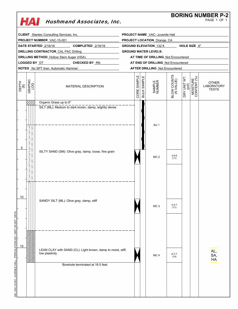
3-5-6(11)
5-4-7(11)
6-7-7(14)
Organic Grass up to 6"
SILT (ML): Medium to dark brown, damp, slightly dense
SILTY SAND (SM): Olive gray, damp, loose, fine grain
SANDY SILT (ML): Olive gray, damp, stiff
LEAN CLAY with SAND (CL): Light brown, damp to moist, stiff,low plasticity
Borehole terminated at 16.5 feet.
AU 1
MC 2
MC 3
MC 4AL,SA,HA
NOTES No SPT liner, Automatic Hammer
GROUND ELEVATION 132 ft
LOGGED BY DT
DATE STARTED 2/16/16
DRILLING METHOD Hollow Stem Auger (HSA) AT TIME OF DRILLING Not Encountered
AT END OF DRILLING Not Encountered
AFTER DRILLING Not Encountered
HOLE SIZE 6"
DRILLING CONTRACTOR CAL PAC Drilling GROUND WATER LEVELS:
CHECKED BY RN
COMPLETED 2/16/16
CO
RE
SA
MP
LE
5
10
15
DE
PT
H(f
t)
GR
AP
HIC
LO
G OTHERLABORATORY
TESTS
SA
MP
LE
NU
MB
ER
MATERIAL DESCRIPTION
BU
LK
SA
MP
LE
BL
OW
CO
UN
TS
(N V
AL
UE
)
DR
Y U
NIT
WT
.(p
cf)
MO
IST
UR
EC
ON
TE
NT
(%
)
PAGE 1 OF 1BORING NUMBER P-2
CLIENT Stantec Consulting Services, Inc.
PROJECT NUMBER VAC-15-001
PROJECT NAME VAC- Juvenile Hall
PROJECT LOCATION Orange, CA
HA
I V
AC
-15-
001,
JU
VE
NIL
E H
ALL
- P
ER
CO
LAT
ION
.GP
J G
INT
US
.GD
T
3/9
/16
Hushmand Associates, Inc.
APPENDIX B LABORATORY TEST RESULTS
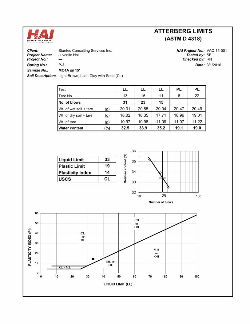
Client: Stantec Consulting Services Inc. VAC-15-001Project Name: Juvenile Hall SEProject No.: --- RN
Boring No.: P-2 Date:
Sample No.: MC4A @ 15'
Soil Description: Light Brown, Lean Clay with Sand (CL)
LL LL LL PL PL
13 15 11 6 22
31 23 15
Wt. of wet soil + tare (g) 20.31 20.85 20.04 20.47 20.49
Wt. of dry soil + tare (g) 18.02 18.35 17.71 18.96 19.01
Wt. of tare (g) 10.97 10.98 11.09 11.07 11.22
Water content (%) 32.5 33.9 35.2 19.1 19.0
Liquid Limit 33
Plastic Limit 19
Plasticity Index 14
CL
ATTERBERG LIMITS(ASTM D 4318)
3/1/2016
HAI Project No.:Tested by:
Checked by:
USCS
No. of blows
Tare No.
Test
0
10
20
30
40
50
60
0 10 20 30 40 50 60 70 80 90 100
PL
AS
TIC
ITY
IN
DE
X (
PI)
LIQUID LIMIT (LL)
CL - ML
CL or
OL
CH or
OH
ML orOL
MHor
OH
32
33
34
35
36
10 100
Mo
istu
re c
on
ten
t (%
)
Number of blows
25
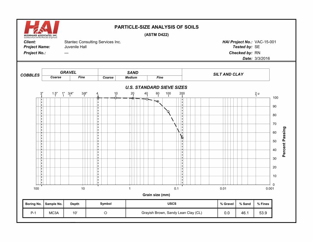
Stantec Consulting Services Inc. VAC-15-001Juvenile Hall SE
RN
Date:
Boring No. Sample No. Depth % Gravel % Sand % Fines
P-1 MC3A 10' 0.0 46.1 53.9
PARTICLE-SIZE ANALYSIS OF SOILS
---
(ASTM D422)
Client: HAI Project No.:Project Name:
Checked by:
U.S. STANDARD SIEVE SIZES
USCS
Tested by:
Project No.:
3/3/2016
Grayish Brown, Sandy Lean Clay (CL)
Symbol
SANDCoarse Medium Fine
0
10
20
30
40
50
60
70
80
90
100
0.0010.010.1110100
Per
cen
t P
assi
ng
Grain size (mm)
1"
GRAVELCoarse Fine
SILT AND CLAYCOBBLES
3" 4 10 20 40 100 2 μ200603/4" 3/8"1.5"
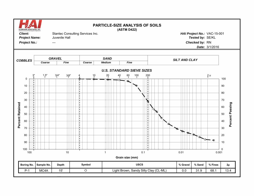
Stantec Consulting Services Inc. VAC-15-001Juvenile Hall SE/KL
RN
Date:
Boring No. Sample No. Depth % Gravel % Sand % Fines 2µ
P-1 MC4A 15' 0.0 31.9 68.1 13.4
PARTICLE-SIZE ANALYSIS OF SOILS
---
(ASTM D422)Client: HAI Project No.:
Tested by:Project Name:
Project No.: Checked by:
U.S. STANDARD SIEVE SIZES
3/1/2016
USCS
Light Brown, Sandy Silty Clay (CL-ML)
Symbol
SANDCoarse Medium Fine
0
10
20
30
40
50
60
70
80
90
100 0
10
20
30
40
50
60
70
80
90
100
0.0010.010.1110100
Per
cen
t R
etai
ned
Per
cen
t P
assi
ng
Grain size (mm)
GRAVELCoarse Fine
SILT AND CLAYCOBBLES
3" 4 10 20 40 100 2 μ200603/4" 3/8"1.5"
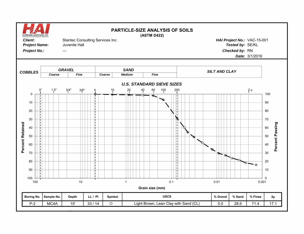
Stantec Consulting Services Inc. VAC-15-001Juvenile Hall SE/KL
RN
Date:
Boring No. Sample No. Depth LL / PI Symbol % Gravel % Sand % Fines 2µ
P-2 MC4A 15' 33 / 14 0.0 28.6 71.4 17.1
U.S. STANDARD SIEVE SIZES
3/1/2016
USCS
Light Brown, Lean Clay with Sand (CL)
PARTICLE-SIZE ANALYSIS OF SOILS
---
(ASTM D422)Client: HAI Project No.:
Tested by:Project Name:
Project No.: Checked by:
SANDCoarse Medium Fine
0
10
20
30
40
50
60
70
80
90
100 0
10
20
30
40
50
60
70
80
90
100
0.0010.010.1110100
Per
cen
t R
etai
ned
Per
cen
t P
assi
ng
Grain size (mm)
GRAVELCoarse Fine
SILT AND CLAYCOBBLES
3" 4 10 20 40 100 2 μ200603/4" 3/8"1.5"
APPENDIX C PERCOLATION TEST DATA SHEETS
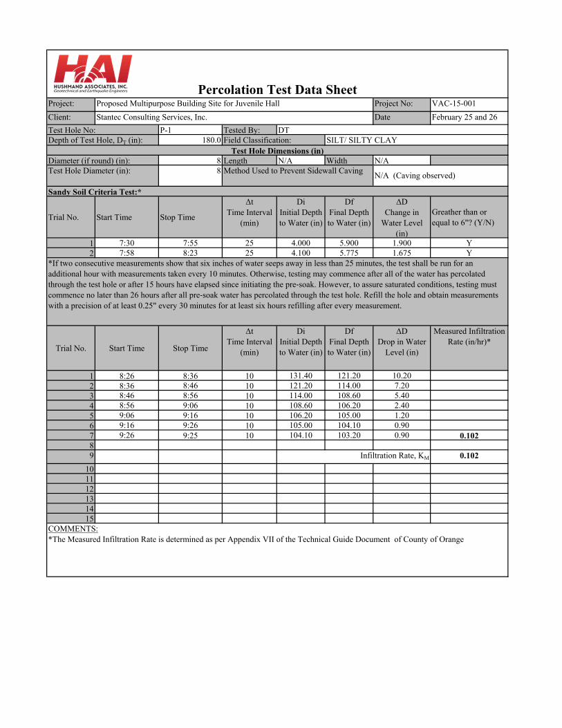
Project: Project No: VAC-15-001
Client: Date February 25 and 26
P-1 Tested By:180.0
8 Length N/A Width N/A8
Trial No. Start Time Stop Time
ΔtTime Interval
(min)
DiInitial Depth to Water (in)
DfFinal Depth to Water (in)
ΔDChange in
Water Level (in)
Greather than or equal to 6"? (Y/N)
1 7:30 7:55 25 4.000 5.900 1.900 Y2 7:58 8:23 25 4.100 5.775 1.675 Y
Trial No. Start Time Stop Time
ΔtTime Interval
(min)
DiInitial Depth to Water (in)
DfFinal Depth to Water (in)
ΔDDrop in Water
Level (in)
Measured Infiltration Rate (in/hr)*
1 8:26 8:36 10 131.40 121.20 10.202 8:36 8:46 10 121.20 114.00 7.203 8:46 8:56 10 114.00 108.60 5.404 8:56 9:06 10 108.60 106.20 2.405 9:06 9:16 10 106.20 105.00 1.206 9:16 9:26 10 105.00 104.10 0.907 9:26 9:25 10 104.10 103.20 0.90 0.10289 0.102
101112131415
Sandy Soil Criteria Test:*
*If two consecutive measurements show that six inches of water seeps away in less than 25 minutes, the test shall be run for an additional hour with measurements taken every 10 minutes. Otherwise, testing may commence after all of the water has percolated through the test hole or after 15 hours have elapsed since initiating the pre‐soak. However, to assure saturated conditions, testing must commence no later than 26 hours after all pre‐soak water has percolated through the test hole. Refill the hole and obtain measurements with a precision of at least 0.25" every 30 minutes for at least six hours refilling after every measurement.
COMMENTS:*The Measured Infiltration Rate is determined as per Appendix VII of the Technical Guide Document of County of Orange
Test Hole Diameter (in): Method Used to Prevent Sidewall CavingN/A (Caving observed)
Infiltration Rate, KM
Depth of Test Hole, DT (in): Field Classification: SILT/ SILTY CLAYTest Hole Dimensions (in)
Diameter (if round) (in):
Percolation Test Data Sheet
Test Hole No: DT
Stantec Consulting Services, Inc.
Proposed Multipurpose Building Site for Juvenile Hall

Project: Project No: VAC-15-001
Client: Date 2/17/2016
P-2 Tested By:180.0
8 Length N/A Width N/A8
Trial No. Start Time Stop Time
ΔtTime Interval
(min)
DiInitial Depth to Water (in)
DfFinal Depth to Water (in)
ΔDChange in
Water Level (in)
Greather than or equal to 6"? (Y/N)
1 7:39 8:04 25 48.000 92.100 44.100 Y2 8:06 8:31 25 48.000 85.8 37.800 Y
Trial No. Start Time Stop Time
ΔtTime Interval
(min)
DiInitial Depth to Water (in)
DfFinal Depth to Water (in)
ΔDDrop in Water
Level (in)
Measured Infiltration Rate (in/hr)*
1 8:33 8:43 10 132.00 110.70 21.302 8:43 8:53 10 110.70 101.10 9.603 8:53 9:03 10 101.10 94.80 6.304 9:03 9:13 10 94.80 90.60 4.205 9:13 9:23 10 90.60 87.90 2.706 9:23 9:33 10 87.90 85.80 2.10 0.284789 0.284
101112131415
Depth of Test Hole, DT (in): Field Classification: SILT/ SANDY SILT
Percolation Test Data SheetProposed Multipurpose Building Site for Juvenile Hall
Stantec Consulting Services, Inc.
Test Hole No: DT
*If two consecutive measurements show that six inches of water seeps away in less than 25 minutes, the test shall be run for an additional hour with measurements taken every 10 minutes. Otherwise, testing may commence after all of the water has percolated through the test hole or after 15 hours have elapsed since initiating the pre‐soak. However, to assure saturated conditions, testing must commence no later than 26 hours after all pre‐soak water has percolated through the test hole. Refill the hole and obtain measurements with a precision of at least 0.25" every 30 minutes for at least six hours refilling after every measurement.
Infiltration Rate*, KM
COMMENTS:*The Measured Infiltration Rate is determined as per Appendix VII of the Technical Guide Document of County of Orange
Test Hole Dimensions (in)Diameter (if round) (in):Test Hole Diameter (in): Method Used to Prevent Sidewall Caving
N/A (Caving observed)
Sandy Soil Criteria Test:*
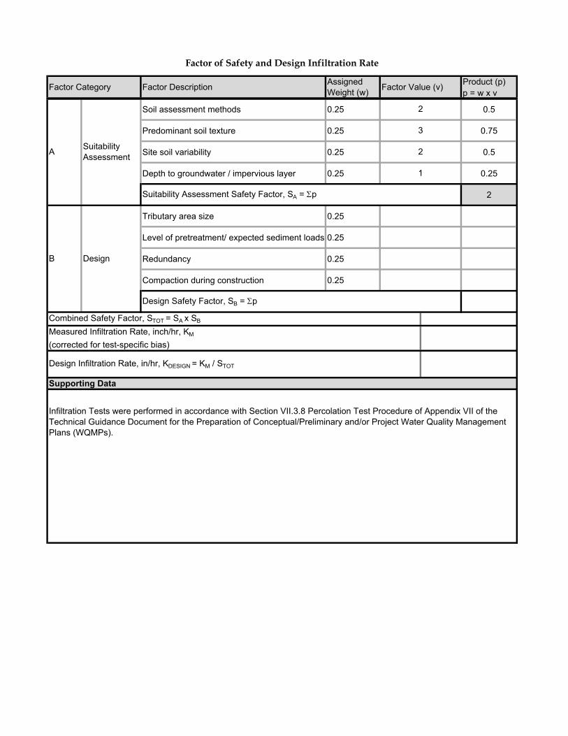
Product (p)p = w x v
Soil assessment methods 0.25 0.5
Predominant soil texture 0.25 0.75
Site soil variability 0.25 0.5
Depth to groundwater / impervious layer 0.25 0.25
2
Tributary area size 0.25
Level of pretreatment/ expected sediment loads 0.25
Redundancy 0.25
Compaction during construction 0.25
Factor of Safety and Design Infiltration Rate
Factor Category Factor DescriptionAssigned Weight (w)
Factor Value (v)
Design Infiltration Rate, in/hr, KDESIGN = KM / STOT
1
Suitability Assessment Safety Factor, SA = p
B Design
Design Safety Factor, SB = p
ASuitability Assessment
2
3
2
Combined Safety Factor, STOT = SA x SB
Measured Infiltration Rate, inch/hr, KM
(corrected for test-specific bias)
Supporting Data
Infiltration Tests were performed in accordance with Section VII.3.8 Percolation Test Procedure of Appendix VII of the Technical Guidance Document for the Preparation of Conceptual/Preliminary and/or Project Water Quality Management Plans (WQMPs).
ATTACHMENT D
CALCULATIONS
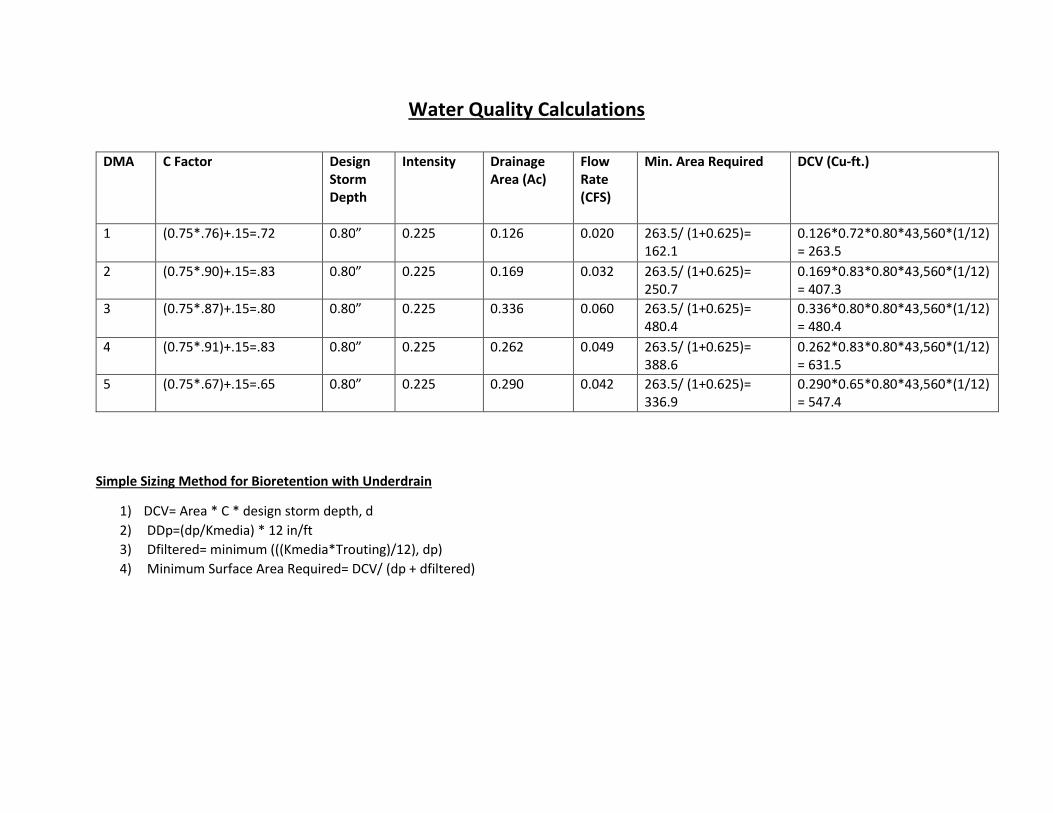
Water Quality Calculations
Simple Sizing Method for Bioretention with Underdrain
1) DCV= Area * C * design storm depth, d
2) DDp=(dp/Kmedia) * 12 in/ft
3) Dfiltered= minimum (((Kmedia*Trouting)/12), dp)
4) Minimum Surface Area Required= DCV/ (dp + dfiltered)
DMA C Factor Design
Storm
Depth
Intensity Drainage
Area (Ac)
Flow
Rate
(CFS)
Min. Area Required DCV (Cu-ft.)
1 (0.75*.76)+.15=.72 0.80” 0.225 0.126 0.020 263.5/ (1+0.625)=
162.1
0.126*0.72*0.80*43,560*(1/12)
= 263.5
2 (0.75*.90)+.15=.83 0.80” 0.225 0.169 0.032 263.5/ (1+0.625)=
250.7
0.169*0.83*0.80*43,560*(1/12)
= 407.3
3 (0.75*.87)+.15=.80 0.80” 0.225 0.336 0.060 263.5/ (1+0.625)=
480.4
0.336*0.80*0.80*43,560*(1/12)
= 480.4
4 (0.75*.91)+.15=.83 0.80” 0.225 0.262 0.049 263.5/ (1+0.625)=
388.6
0.262*0.83*0.80*43,560*(1/12)
= 631.5
5 (0.75*.67)+.15=.65 0.80” 0.225 0.290 0.042 263.5/ (1+0.625)=
336.9
0.290*0.65*0.80*43,560*(1/12)
= 547.4

ATTACHMENT E
EDUCATION MATERIALS

For more information,please call the
Orange County Stormwater Program at 1-877-89-SPILL (1-877-897-7455)
or visit www.ocwatersheds.com
To report a spill, call the
Orange County 24-Hour Water Pollution Problem
Reporting Hotline at 1-877-89-SPILL (1-877-897-7455).
For emergencies, dial 911.
Proper MaintenancePractices for
Your Business
The Ocean Beginsat Your Front Door
P R O J E C T
P R E V E N T I O N
Help Prevent Ocean Pollution:
Preventing waterpollution at yourcommercial/industrial site
Clean beaches and healthy creeks, rivers, bays and ocean are important to Orange County. However, many landscape and building maintenance activities can lead to water pollution if you’re not careful. Paint, chemicals, plant clippings and other materials can be blown or washed into storm drains that flow to the ocean. Unlike water in sanitary sewers (from sinks and toilets), water in storm drains is not treated before entering our waterways.
You would never pour soap or fertilizers into the ocean, so why would you let them enter the storm drains? Follow these easy tips to help prevent water pollution.
Some types of industrial facilities are required to obtain coverage under the State General Industrial Permit. For more information visit: www.swrcb.ca.gov/stormwater/industrial.html
Printed on Recycled Paper

Tips for Pool Maintenance Call your trash hauler to replace leaking
dumpsters.
Do not dump any toxic substance or liquid waste on the pavement, the ground, or near a storm drain. Even materials that seem harmless such as latex paint or biodegradable cleaners can damage the environment.
Recycle paints, solvents and other materials. For more information about recycling and collection centers, visit www.oclandfills.com.
Store materials indoors or under cover and away from storm drains.
Use a construction and demolition recycling company to recycle lumber, paper, cardboard, metals, masonry, carpet, plastic, pipes, drywall, rocks, dirt, and green waste. For a listing of construction and demolition recycling locations in your area, visit
www.ciwmb.ca.gov/recycle.
Properly label materials. Familiarize employees with Material Safety Data Sheets.
Landscape Maintenance
Compost grass clippings, leaves, sticks and other vegetation, or dispose of it at a permitted landfill or in green waste containers. Do not dispose of these materials in the street, gutter or storm drain.
Irrigate slowly and inspect the system for leaks, overspraying and runoff. Adjust automatic timers to avoid overwatering.
Follow label directions for the use and disposal of fertilizers and pesticides.
Do not apply pesticides or fertilizers if rain is expected within 48 hours or if wind speeds are above 5 mph.
Do not spray pesticides within 100 feet of waterways.
Fertilizers should be worked into the soil rather than dumped onto the surface.
If fertilizer is spilled on the pavement or sidewalk, sweep it up immediately and place it back in the container.
Building Maintenance
Never allow washwater, sweepings or sediment to enter the storm drain.
Sweep up dry spills and use cat litter, towels or similar materials to absorb wet spills. Dispose of it in the trash.
If you wash your building, sidewalk or parking lot, you must contain the water. Use a shop vac to collect the water and contact your city or sanitation agency for proper disposal information. Do not let water enter the street, gutter or storm drain.
Use drop cloths underneath outdoor painting, scraping, and sandblasting work, and properly dispose of materials in the trash.
Use a ground cloth or oversized tub for mixing paint and cleaning tools.
Use a damp mop or broom to clean floors.
Cover dumpsters to keep insects, animals, rainwater and sand from entering. Keep the area around the dumpster clear of trash and debris. Do not overfill the dumpster.
P R O J E C T
P R E V E N T I O N
Proper Maintenance Practices for your Business
Never Dispose of Anything in the Storm
Drain.
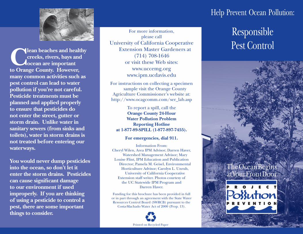
Clean beaches and healthy creeks, rivers, bays and ocean are important
to Orange County. However, many common activities such as pest control can lead to water pollution if you’re not careful. Pesticide treatments must be planned and applied properly to ensure that pesticides do not enter the street, gutter or storm drain. Unlike water in sanitary sewers (from sinks and toilets), water in storm drains is not treated before entering our waterways.
You would never dump pesticides into the ocean, so don’t let it enter the storm drains. Pesticides can cause significant damage to our environment if used improperly. If you are thinking of using a pesticide to control a pest, there are some important things to consider.
For more information, please call
University of California Cooperative Extension Master Gardeners at
(714) 708-1646 or visit these Web sites:
www.uccemg.orgwww.ipm.ucdavis.edu
For instructions on collecting a specimen sample visit the Orange County
Agriculture Commissioner’s website at: http://www.ocagcomm.com/ser_lab.asp
To report a spill, call theOrange County 24-HourWater Pollution Problem
Reporting Hotlineat 1-877-89-SPILL (1-877-897-7455).
For emergencies, dial 911.
Information From:Cheryl Wilen, Area IPM Advisor; Darren Haver,
Watershed Management Advisor; MaryLouise Flint, IPM Education and Publication
Director; Pamela M. Geisel, Environmental Horticulture Advisor; Carolyn L. Unruh,
University of California Cooperative Extension staff writer. Photos courtesy of
the UC Statewide IPM Program and Darren Haver.
Funding for this brochure has been provided in fullor in part through an agreement with the State WaterResources Control Board (SWRCB) pursuant to the
Costa-Machado Water Act of 2000 (Prop. 13).
Help Prevent Ocean Pollution:
The Ocean Beginsat Your Front Door
Responsible Pest Control
Printed on Recycled Paper
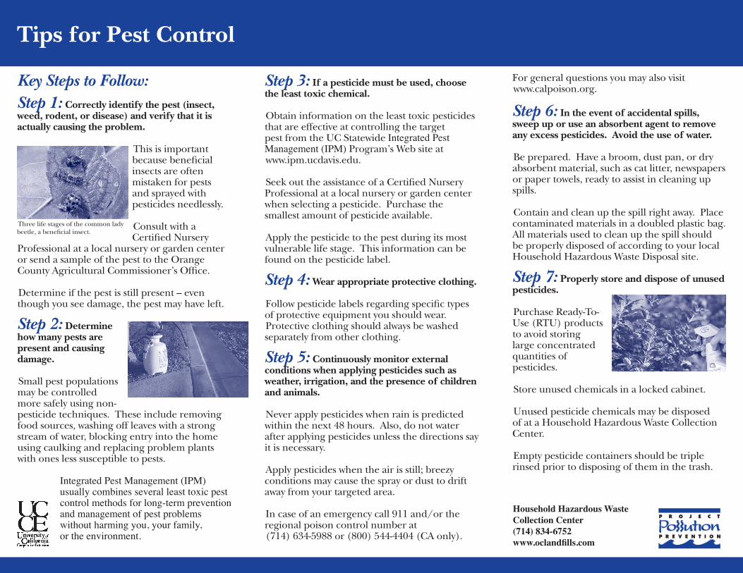
Key Steps to Follow:Step 1: Correctly identify the pest (insect, weed, rodent, or disease) and verify that it is actually causing the problem.
This is important because beneficial insects are often mistaken for pests and sprayed with pesticides needlessly.
Consult with a Certified Nursery
Professional at a local nursery or garden center or send a sample of the pest to the Orange County Agricultural Commissioner’s Office.
Determine if the pest is still present – even though you see damage, the pest may have left.
Step 2: Determine how many pests are present and causing damage.
Small pest populations may be controlled more safely using non-pesticide techniques. These include removing food sources, washing off leaves with a strong stream of water, blocking entry into the home using caulking and replacing problem plants with ones less susceptible to pests.
Step 3: If a pesticide must be used, choose the least toxic chemical.
Obtain information on the least toxic pesticides that are effective at controlling the target pest from the UC Statewide Integrated Pest Management (IPM) Program’s Web site at www.ipm.ucdavis.edu.
Seek out the assistance of a Certified Nursery Professional at a local nursery or garden center when selecting a pesticide. Purchase the smallest amount of pesticide available.
Apply the pesticide to the pest during its most vulnerable life stage. This information can be found on the pesticide label.
Step 4: Wear appropriate protective clothing.
Follow pesticide labels regarding specific types of protective equipment you should wear. Protective clothing should always be washed separately from other clothing.
Step 5: Continuously monitor external conditions when applying pesticides such as weather, irrigation, and the presence of children and animals.
Never apply pesticides when rain is predicted within the next 48 hours. Also, do not water after applying pesticides unless the directions say it is necessary.
Apply pesticides when the air is still; breezy conditions may cause the spray or dust to drift away from your targeted area.
In case of an emergency call 911 and/or the regional poison control number at (714) 634-5988 or (800) 544-4404 (CA only).
For general questions you may also visit www.calpoison.org. Step 6: In the event of accidental spills, sweep up or use an absorbent agent to remove any excess pesticides. Avoid the use of water.
Be prepared. Have a broom, dust pan, or dry absorbent material, such as cat litter, newspapers or paper towels, ready to assist in cleaning up spills.
Contain and clean up the spill right away. Place contaminated materials in a doubled plastic bag. All materials used to clean up the spill should be properly disposed of according to your local Household Hazardous Waste Disposal site.
Step 7: Properly store and dispose of unused pesticides.
Purchase Ready-To-Use (RTU) products to avoid storing large concentrated quantities of pesticides.
Store unused chemicals in a locked cabinet.
Unused pesticide chemicals may be disposed of at a Household Hazardous Waste Collection Center.
Empty pesticide containers should be triple rinsed prior to disposing of them in the trash.
Household Hazardous Waste Collection Center(714) 834-6752www.oclandfills.com
Integrated Pest Management (IPM) usually combines several least toxic pest control methods for long-term prevention and management of pest problems without harming you, your family, or the environment.
Three life stages of the common lady beetle, a beneficial insect.
Tips for Pest Control

Help Prevent Ocean Pollution:
The Tips contained in this brochure provide useful information about how you can keep
materials and washwater from entering the storm drain system. If you have other suggestions for
how water and materials may be contained, please contact your city’s stormwater representative or call the Orange County Stormwater Program.
Tips for Using Concrete
and MortarC lean beaches
and healthy creeks, rivers, bays,
and ocean are important to Orange County. However, many common activities can lead to water pollution if you’re not careful. Materials and excess concrete or mortar can be blown or washed into the storm drains that flow to the ocean. Unlike water in sanitary sewers (from sinks and toilets), water in storm drains is not treated before entering our waterways.
You would never throw building materials into the ocean, so don’t let them enter the storm drains. Follow these easy tips to help prevent water pollution.
For more information,please call the
Orange County Stormwater Program at 1-877-89-SPILL (1-877-897-7455)
or visit www.ocwatersheds.com.
To report a spill, call the
Orange County 24-Hour Water Pollution Reporting Hotline at 1-877-89-SPILL (1-877-897-7455).
For emergencies, dial 911.
The Ocean Beginsat Your Front Door
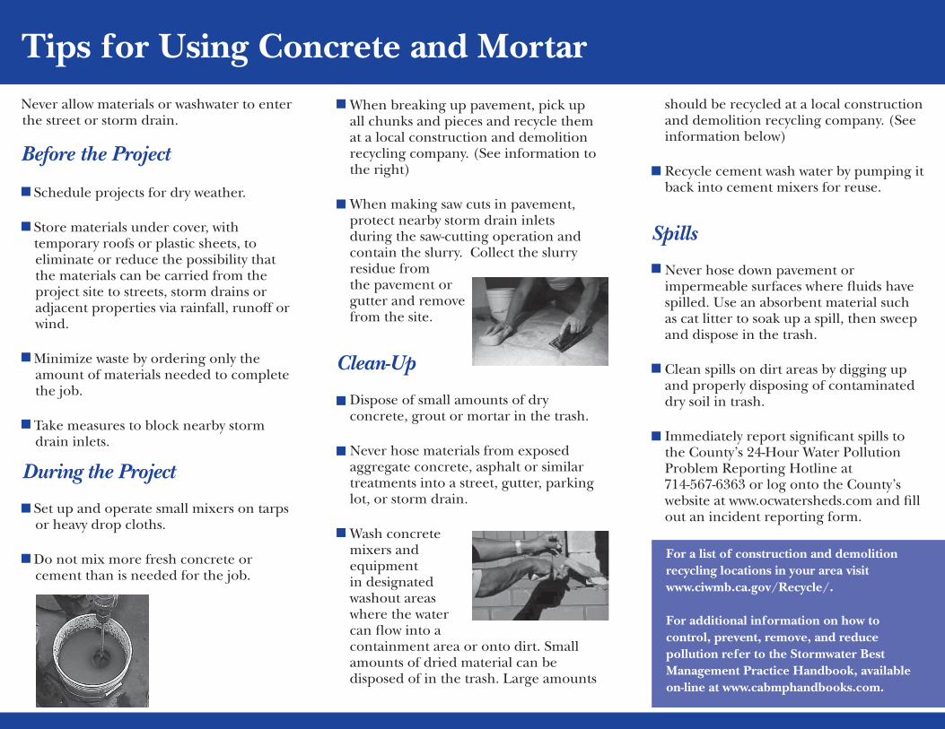
Never allow materials or washwater to enter the street or storm drain.
Before the Project
•Schedule projects for dry weather.
•Store materials under cover, with temporary roofs or plastic sheets, to eliminate or reduce the possibility that the materials can be carried from the project site to streets, storm drains or adjacent properties via rainfall, runoff or wind.
•Minimize waste by ordering only the amount of materials needed to complete the job.
•Take measures to block nearby storm drain inlets.
During the Project
•Set up and operate small mixers on tarps or heavy drop cloths.
•Do not mix more fresh concrete or cement than is needed for the job.
•When breaking up pavement, pick up all chunks and pieces and recycle them at a local construction and demolition recycling company. (See information to the right)
•When making saw cuts in pavement, protect nearby storm drain inlets during the saw-cutting operation and contain the slurry. Collect the slurry residue from the pavement or gutter and remove from the site.
Clean-Up
•Dispose of small amounts of dry concrete, grout or mortar in the trash.
•Never hose materials from exposed aggregate concrete, asphalt or similar treatments into a street, gutter, parking lot, or storm drain.
•Wash concrete mixers and equipment in designated washout areas where the water can flow into a containment area or onto dirt. Small amounts of dried material can be disposed of in the trash. Large amounts
should be recycled at a local construction and demolition recycling company. (See information below)
•Recycle cement wash water by pumping it back into cement mixers for reuse.
Spills
•Never hose down pavement or impermeable surfaces where fluids have spilled. Use an absorbent material such as cat litter to soak up a spill, then sweep and dispose in the trash.
•Clean spills on dirt areas by digging up and properly disposing of contaminated dry soil in trash.
•Immediately report significant spills to the County’s 24-Hour Water Pollution Problem Reporting Hotline at
714-567-6363 or log onto the County’s website at www.ocwatersheds.com and fill out an incident reporting form.
For a list of construction and demolition recycling locations in your area visit www.ciwmb.ca.gov/Recycle/.
For additional information on how to control, prevent, remove, and reduce pollution refer to the Stormwater Best Management Practice Handbook, available on-line at www.cabmphandbooks.com.
Tips for Using Concrete and Mortar
ATTACHMENT F
OPERATIONS AND MAINTENANCE (O&M) PLAN
EXHIBIT B – INSPECTION AND MAINTENANCE FORM
Operations and Maintenance (O&M) Plan
Water Quality Management Plan for
Orange County Juvenile Hall Multipurpose Rehabilitation Center
331 The City Drive South
Orange, CA 92686
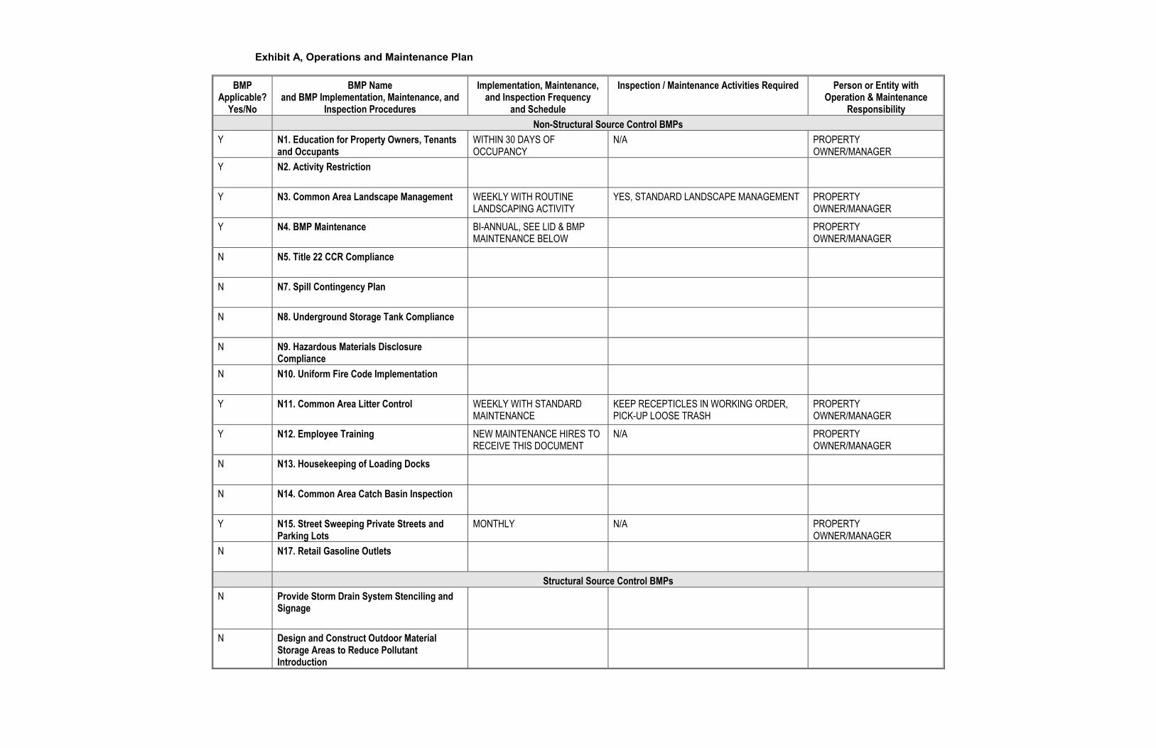
Exhibit A, Operations and Maintenance Plan
BMP Applicable?
Yes/No
BMP Name and BMP Implementation, Maintenance, and
Inspection Procedures
Implementation, Maintenance, and Inspection Frequency
and Schedule
Inspection / Maintenance Activities Required Person or Entity with Operation & Maintenance
Responsibility
Non-Structural Source Control BMPs
Y N1. Education for Property Owners, Tenants and Occupants
WITHIN 30 DAYS OF OCCUPANCY
N/A PROPERTY OWNER/MANAGER
Y N2. Activity Restriction
Y N3. Common Area Landscape Management
WEEKLY WITH ROUTINE LANDSCAPING ACTIVITY
YES, STANDARD LANDSCAPE MANAGEMENT PROPERTY OWNER/MANAGER
Y N4. BMP Maintenance
BI-ANNUAL, SEE LID & BMP MAINTENANCE BELOW
PROPERTY OWNER/MANAGER
N N5. Title 22 CCR Compliance
N N7. Spill Contingency Plan
N N8. Underground Storage Tank Compliance
N N9. Hazardous Materials Disclosure Compliance
N N10. Uniform Fire Code Implementation
Y N11. Common Area Litter Control
WEEKLY WITH STANDARD MAINTENANCE
KEEP RECEPTICLES IN WORKING ORDER, PICK-UP LOOSE TRASH
PROPERTY OWNER/MANAGER
Y N12. Employee Training
NEW MAINTENANCE HIRES TO RECEIVE THIS DOCUMENT
N/A PROPERTY OWNER/MANAGER
N N13. Housekeeping of Loading Docks
N N14. Common Area Catch Basin Inspection
Y N15. Street Sweeping Private Streets and Parking Lots
MONTHLY N/A PROPERTY OWNER/MANAGER
N N17. Retail Gasoline Outlets
Structural Source Control BMPs
N Provide Storm Drain System Stenciling and Signage
N Design and Construct Outdoor Material Storage Areas to Reduce Pollutant Introduction
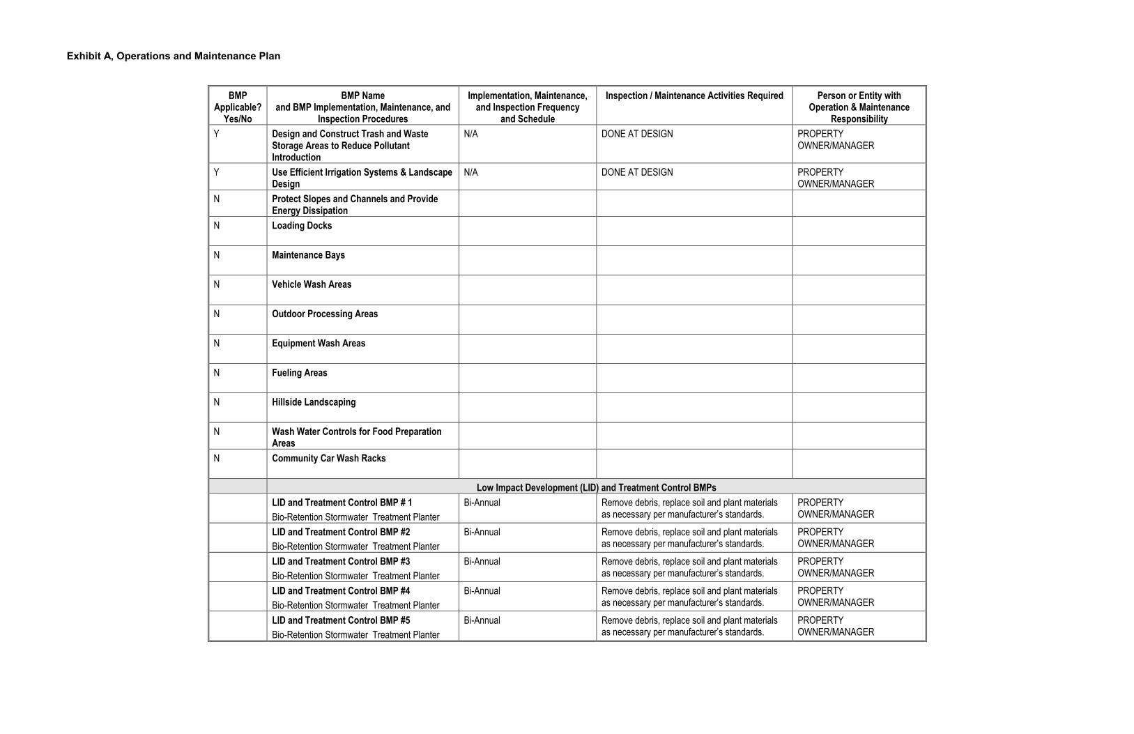
Exhibit A, Operations and Maintenance Plan
BMP Applicable?
Yes/No
BMP Name and BMP Implementation, Maintenance, and
Inspection Procedures
Implementation, Maintenance, and Inspection Frequency
and Schedule
Inspection / Maintenance Activities Required Person or Entity with Operation & Maintenance
Responsibility
Y Design and Construct Trash and Waste Storage Areas to Reduce Pollutant Introduction
N/A DONE AT DESIGN PROPERTY OWNER/MANAGER
Y Use Efficient Irrigation Systems & Landscape Design
N/A DONE AT DESIGN PROPERTY OWNER/MANAGER
N Protect Slopes and Channels and Provide Energy Dissipation
N Loading Docks
N Maintenance Bays
N Vehicle Wash Areas
N Outdoor Processing Areas
N Equipment Wash Areas
N Fueling Areas
N Hillside Landscaping
N Wash Water Controls for Food Preparation Areas
N Community Car Wash Racks
Low Impact Development (LID) and Treatment Control BMPs
LID and Treatment Control BMP # 1
Bio-Retention Stormwater Treatment Planter
Bi-Annual Remove debris, replace soil and plant materials as necessary per manufacturer’s standards.
PROPERTY OWNER/MANAGER
LID and Treatment Control BMP #2
Bio-Retention Stormwater Treatment Planter
Bi-Annual Remove debris, replace soil and plant materials as necessary per manufacturer’s standards.
PROPERTY OWNER/MANAGER
LID and Treatment Control BMP #3
Bio-Retention Stormwater Treatment Planter
Bi-Annual Remove debris, replace soil and plant materials as necessary per manufacturer’s standards.
PROPERTY OWNER/MANAGER
LID and Treatment Control BMP #4
Bio-Retention Stormwater Treatment Planter
Bi-Annual Remove debris, replace soil and plant materials as necessary per manufacturer’s standards.
PROPERTY OWNER/MANAGER
LID and Treatment Control BMP #5
Bio-Retention Stormwater Treatment Planter
Bi-Annual Remove debris, replace soil and plant materials as necessary per manufacturer’s standards.
PROPERTY OWNER/MANAGER

Exhibit A, Operations and Maintenance Plan
Today’s Date:
Name of Person Performing Activity (Printed):
Signature:
BMP Name (As Shown in O&M Plan)
Brief Description of Implementation, Maintenance, and Inspection Activity Performed
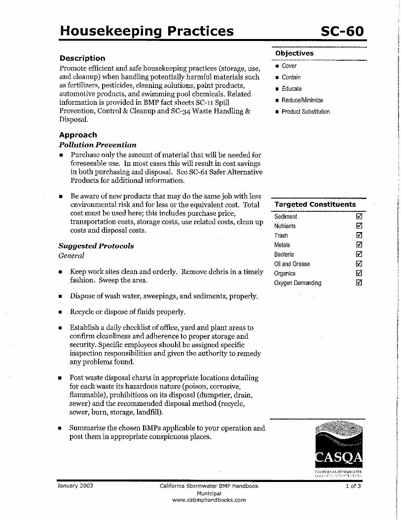
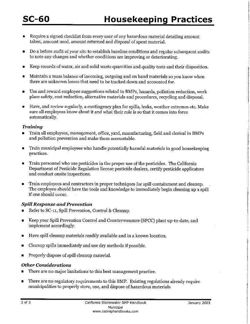
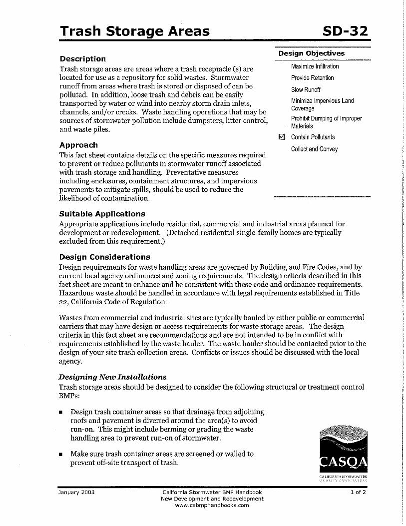
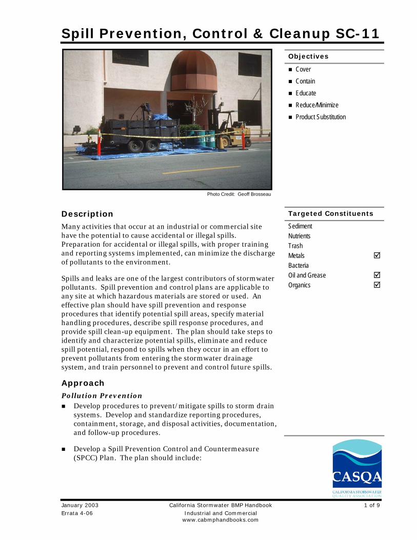
Spill Prevention, Control & Cleanup SC-11
Objectives
Cover
Contain
Educate
Reduce/Minimize
Product Substitution
Targeted Constituents
Errata 4-06 Industrial and Commercial www.cabmphandbooks.com
Description Many activities that occur at an industrial or commercial site have the potential to cause accidental or illegal spills. Preparation for accidental or illegal spills, with proper training and reporting systems implemented, can minimize the discharge of pollutants to the environment.
Spills and leaks are one of the largest contributors of stormwater pollutants. Spill prevention and control plans are applicable to any site at which hazardous materials are stored or used. An effective plan should have spill prevention and response procedures that identify potential spill areas, specify material handling procedures, describe spill response procedures, and provide spill clean-up equipment. The plan should take steps to identify and characterize potential spills, eliminate and reduce spill potential, respond to spills when they occur in an effort to prevent pollutants from entering the stormwater drainage system, and train personnel to prevent and control future spills.
Approach Pollution Prevention
Develop procedures to prevent/mitigate spills to storm drain systems. Develop and standardize reporting procedures, containment, storage, and disposal activities, documentation, and follow-up procedures.
Develop a Spill Prevention Control and Countermeasure (SPCC) Plan. The plan should include:
Sediment Nutrients Trash Metals Bacteria Oil and Grease Organics
Photo Credit: Geoff Brosseau
January 2003 California Stormwater BMP Handbook 1 of 9
SC-11 Spill Prevention, Control & Cleanup
- Description of the facility, owner and address, activities and chemicals present
- Facility map
- Notification and evacuation procedures
- Cleanup instructions
- Identification of responsible departments
- Identify key spill response personnel
Recycle, reclaim, or reuse materials whenever possible. This will reduce the amount of process materials that are brought into the facility.
Suggested Protocols (including equipment needs) Spill Prevention
Develop procedures to prevent/mitigate spills to storm drain systems. Develop and standardize reporting procedures, containment, storage, and disposal activities, documentation, and follow-up procedures.
If consistent illegal dumping is observed at the facility:
- Post “No Dumping” signs with a phone number for reporting illegal dumping and disposal. Signs should also indicate fines and penalties applicable for illegal dumping.
- Landscaping and beautification efforts may also discourage illegal dumping.
- Bright lighting and/or entrance barriers may also be needed to discourage illegal dumping.
Store and contain liquid materials in such a manner that if the tank is ruptured, the contents will not discharge, flow, or be washed into the storm drainage system, surface waters, or groundwater.
If the liquid is oil, gas, or other material that separates from and floats on water, install a spill control device (such as a tee section) in the catch basins that collects runoff from the storage tank area.
Routine maintenance:
- Place drip pans or absorbent materials beneath all mounted taps, and at all potential drip and spill locations during filling and unloading of tanks. Any collected liquids or soiled absorbent materials must be reused/recycled or properly disposed.
- Store and maintain appropriate spill cleanup materials in a location known to all near the tank storage area; and ensure that employees are familiar with the site’s spill control plan and/or proper spill cleanup procedures.
- Sweep and clean the storage area monthly if it is paved, do not hose down the area to a storm drain.
2 of 9 California Stormwater BMP Handbook January 2003 Industrial and Commercial Errata 4-06
www.cabmphandbooks.com
Spill Prevention, Control & Cleanup SC-11
- Check tanks (and any containment sumps) daily for leaks and spills. Replace tanks that are leaking, corroded, or otherwise deteriorating with tanks in good condition. Collect all spilled liquids and properly dispose of them.
Label all containers according to their contents (e.g., solvent, gasoline).
Label hazardous substances regarding the potential hazard (corrosive, radioactive, flammable, explosive, poisonous).
Prominently display required labels on transported hazardous and toxic materials (per US DOT regulations).
Identify key spill response personnel.
Spill Control and Cleanup Activities Follow the Spill Prevention Control and Countermeasure Plan.
Clean up leaks and spills immediately.
Place a stockpile of spill cleanup materials where it will be readily accessible (e.g., near storage and maintenance areas).
On paved surfaces, clean up spills with as little water as possible. Use a rag for small spills, a damp mop for general cleanup, and absorbent material for larger spills. If the spilled material is hazardous, then the used cleanup materials are also hazardous and must be sent to a certified laundry (rags) or disposed of as hazardous waste. Physical methods for the cleanup of dry chemicals include the use of brooms, shovels, sweepers, or plows.
Never hose down or bury dry material spills. Sweep up the material and dispose of properly.
Chemical cleanups of material can be achieved with the use of adsorbents, gels, and foams. Use adsorbent materials on small spills rather than hosing down the spill. Remove the adsorbent materials promptly and dispose of properly.
For larger spills, a private spill cleanup company or Hazmat team may be necessary.
Reporting Report spills that pose an immediate threat to human health or the environment to the
Regional Water Quality Control Board.
Federal regulations require that any oil spill into a water body or onto an adjoining shoreline be reported to the National Response Center (NRC) at 800-424-8802 (24 hour).
Report spills to local agencies, such as the fire department; they can assist in cleanup.
Establish a system for tracking incidents. The system should be designed to identify the following:
- Types and quantities (in some cases) of wastes
- Patterns in time of occurrence (time of day/night, month, or year)
January 2003 California Stormwater BMP Handbook 3 of 9 Errata 4-06 Industrial and Commercial www.cabmphandbooks.com
SC-11 Spill Prevention, Control & Cleanup
- Mode of dumping (abandoned containers, “midnight dumping” from moving vehicles, direct dumping of materials, accidents/spills)
- Responsible parties
Training Educate employees about spill prevention and cleanup.
Well-trained employees can reduce human errors that lead to accidental releases or spills:
- The employee should have the tools and knowledge to immediately begin cleaning up a spill should one occur.
- Employees should be familiar with the Spill Prevention Control and Countermeasure Plan.
Employees should be educated about aboveground storage tank requirements. Employees responsible for aboveground storage tanks and liquid transfers should be thoroughly familiar with the Spill Prevention Control and Countermeasure Plan and the plan should be readily available.
Train employees to recognize and report illegal dumping incidents.
Other Considerations (Limitations and Regulations) A Spill Prevention Control and Countermeasure Plan (SPCC) is required for facilities that are
subject to the oil pollution regulations specified in Part 112 of Title 40 of the Code of Federal Regulations or if they have a storage capacity of 10,000 gallons or more of petroleum. (Health and Safety Code 6.67)
State regulations also exist for storage of hazardous materials (Health & Safety Code Chapter 6.95), including the preparation of area and business plans for emergency response to the releases or threatened releases.
Consider requiring smaller secondary containment areas (less than 200 sq. ft.) to be connected to the sanitary sewer, prohibiting any hard connections to the storm drain.
Requirements Costs (including capital and operation & maintenance)
Will vary depending on the size of the facility and the necessary controls.
Prevention of leaks and spills is inexpensive. Treatment and/or disposal of contaminated soil or water can be quite expensive.
Maintenance (including administrative and staffing) This BMP has no major administrative or staffing requirements. However, extra time is
needed to properly handle and dispose of spills, which results in increased labor costs.
4 of 9 California Stormwater BMP Handbook January 2003 Industrial and Commercial Errata 4-06
www.cabmphandbooks.com
Spill Prevention, Control & Cleanup SC-11
Supplemental Information Further Detail of the BMP Reporting Record keeping and internal reporting represent good operating practices because they can increase the efficiency of the facility and the effectiveness of BMPs. A good record keeping system helps the facility minimize incident recurrence, correctly respond with appropriate cleanup activities, and comply with legal requirements. A record keeping and reporting system should be set up for documenting spills, leaks, and other discharges, including discharges of hazardous substances in reportable quantities. Incident records describe the quality and quantity of non-stormwater discharges to the storm sewer. These records should contain the following information:
Date and time of the incident
Weather conditions
Duration of the spill/leak/discharge
Cause of the spill/leak/discharge
Response procedures implemented
Persons notified
Environmental problems associated with the spill/leak/discharge
Separate record keeping systems should be established to document housekeeping and preventive maintenance inspections, and training activities. All housekeeping and preventive maintenance inspections should be documented. Inspection documentation should contain the following information:
The date and time the inspection was performed
Name of the inspector
Items inspected
Problems noted
Corrective action required
Date corrective action was taken
Other means to document and record inspection results are field notes, timed and dated photographs, videotapes, and drawings and maps.
Aboveground Tank Leak and Spill Control Accidental releases of materials from aboveground liquid storage tanks present the potential for contaminating stormwater with many different pollutants. Materials spilled, leaked, or lost from
January 2003 California Stormwater BMP Handbook 5 of 9 Errata 4-06 Industrial and Commercial www.cabmphandbooks.com
SC-11 Spill Prevention, Control & Cleanup
tanks may accumulate in soils or on impervious surfaces and be carried away by stormwater runoff.
The most common causes of unintentional releases are:
Installation problems
Failure of piping systems (pipes, pumps, flanges, couplings, hoses, and valves)
External corrosion and structural failure
Spills and overfills due to operator error
Leaks during pumping of liquids or gases from truck or rail car to a storage tank or vice versa
Storage of reactive, ignitable, or flammable liquids should comply with the Uniform Fire Code and the National Electric Code. Practices listed below should be employed to enhance the code requirements:
Tanks should be placed in a designated area.
Tanks located in areas where firearms are discharged should be encapsulated in concrete or the equivalent.
Designated areas should be impervious and paved with Portland cement concrete, free of cracks and gaps, in order to contain leaks and spills.
Liquid materials should be stored in UL approved double walled tanks or surrounded by a curb or dike to provide the volume to contain 10 percent of the volume of all of the containers or 110 percent of the volume of the largest container, whichever is greater. The area inside the curb should slope to a drain.
For used oil or dangerous waste, a dead-end sump should be installed in the drain.
All other liquids should be drained to the sanitary sewer if available. The drain must have a positive control such as a lock, valve, or plug to prevent release of contaminated liquids.
Accumulated stormwater in petroleum storage areas should be passed through an oil/water separator.
Maintenance is critical to preventing leaks and spills. Conduct routine inspections and:
Check for external corrosion and structural failure.
Check for spills and overfills due to operator error.
Check for failure of piping system (pipes, pumps, flanger, coupling, hoses, and valves).
Check for leaks or spills during pumping of liquids or gases from truck or rail car to a storage facility or vice versa.
6 of 9 California Stormwater BMP Handbook January 2003 Industrial and Commercial Errata 4-06
www.cabmphandbooks.com
Spill Prevention, Control & Cleanup SC-11
Visually inspect new tank or container installation for loose fittings, poor welding, and improper or poorly fitted gaskets.
Inspect tank foundations, connections, coatings, and tank walls and piping system. Look for corrosion, leaks, cracks, scratches, and other physical damage that may weaken the tank or container system.
Frequently relocate accumulated stormwater during the wet season.
Periodically conduct integrity testing by a qualified professional.
Vehicle Leak and Spill Control Major spills on roadways and other public areas are generally handled by highly trained Hazmat teams from local fire departments or environmental health departments. The measures listed below pertain to leaks and smaller spills at vehicle maintenance shops.
In addition to implementing the spill prevention, control, and clean up practices above, use the following measures related to specific activities:
Vehicle and Equipment Maintenance Perform all vehicle fluid removal or changing inside or under cover to prevent the run-on of
stormwater and the runoff of spills.
Regularly inspect vehicles and equipment for leaks, and repair immediately.
Check incoming vehicles and equipment (including delivery trucks, and employee and subcontractor vehicles) for leaking oil and fluids. Do not allow leaking vehicles or equipment onsite.
Always use secondary containment, such as a drain pan or drop cloth, to catch spills or leaks when removing or changing fluids.
Immediately drain all fluids from wrecked vehicles.
Store wrecked vehicles or damaged equipment under cover.
Place drip pans or absorbent materials under heavy equipment when not in use.
Use adsorbent materials on small spills rather than hosing down the spill.
Remove the adsorbent materials promptly and dispose of properly.
Promptly transfer used fluids to the proper waste or recycling drums. Don’t leave full drip pans or other open containers lying around.
Oil filters disposed of in trashcans or dumpsters can leak oil and contaminate stormwater. Place the oil filter in a funnel over a waste oil recycling drum to drain excess oil before disposal. Oil filters can also be recycled. Ask your oil supplier or recycler about recycling oil filters.
January 2003 California Stormwater BMP Handbook 7 of 9 Errata 4-06 Industrial and Commercial www.cabmphandbooks.com
SC-11 Spill Prevention, Control & Cleanup
Store cracked batteries in a non-leaking secondary container. Do this with all cracked batteries, even if you think all the acid has drained out. If you drop a battery, treat it as if it is cracked. Put it into the containment area until you are sure it is not leaking.
Vehicle and Equipment Fueling Design the fueling area to prevent the run-on of stormwater and the runoff of spills:
- Cover fueling area if possible.
- Use a perimeter drain or slope pavement inward with drainage to a sump.
- Pave fueling area with concrete rather than asphalt.
If dead-end sump is not used to collect spills, install an oil/water separator.
Install vapor recovery nozzles to help control drips as well as air pollution.
Discourage “topping-off’ of fuel tanks.
Use secondary containment when transferring fuel from the tank truck to the fuel tank.
Use adsorbent materials on small spills and general cleaning rather than hosing down the area. Remove the adsorbent materials promptly.
Carry out all Federal and State requirements regarding underground storage tanks, or install above ground tanks.
Do not use mobile fueling of mobile industrial equipment around the facility; rather, transport the equipment to designated fueling areas.
Keep your Spill Prevention Control and Countermeasure (SPCC) Plan up-to-date.
Train employees in proper fueling and cleanup procedures.
Industrial Spill Prevention Response For the purposes of developing a spill prevention and response program to meet the stormwater regulations, facility managers should use information provided in this fact sheet and the spill prevention/response portions of the fact sheets in this handbook, for specific activities. The program should:
Integrate with existing emergency response/hazardous materials programs (e.g., Fire Department)
Develop procedures to prevent/mitigate spills to storm drain systems
Identify responsible departments
Develop and standardize reporting procedures, containment, storage, and disposal activities, documentation, and follow-up procedures
Address spills at municipal facilities, as well as public areas
8 of 9 California Stormwater BMP Handbook January 2003 Industrial and Commercial Errata 4-06
www.cabmphandbooks.com
Spill Prevention, Control & Cleanup SC-11
Provide training concerning spill prevention, response and cleanup to all appropriate personnel
References and Resources California’s Nonpoint Source Program Plan http://www.swrcb.ca.gov/nps/index.html
Clark County Storm Water Pollution Control Manual http://www.co.clark.wa.us/pubworks/bmpman.pdf
King County Storm Water Pollution Control Manual http://dnr.metrokc.gov/wlr/dss/spcm.htm
Santa Clara Valley Urban Runoff Pollution Prevention Program http://www.scvurppp.org
The Stormwater Managers Resource Center http://www.stormwatercenter.net/
January 2003 California Stormwater BMP Handbook 9 of 9 Errata 4-06 Industrial and Commercial www.cabmphandbooks.com
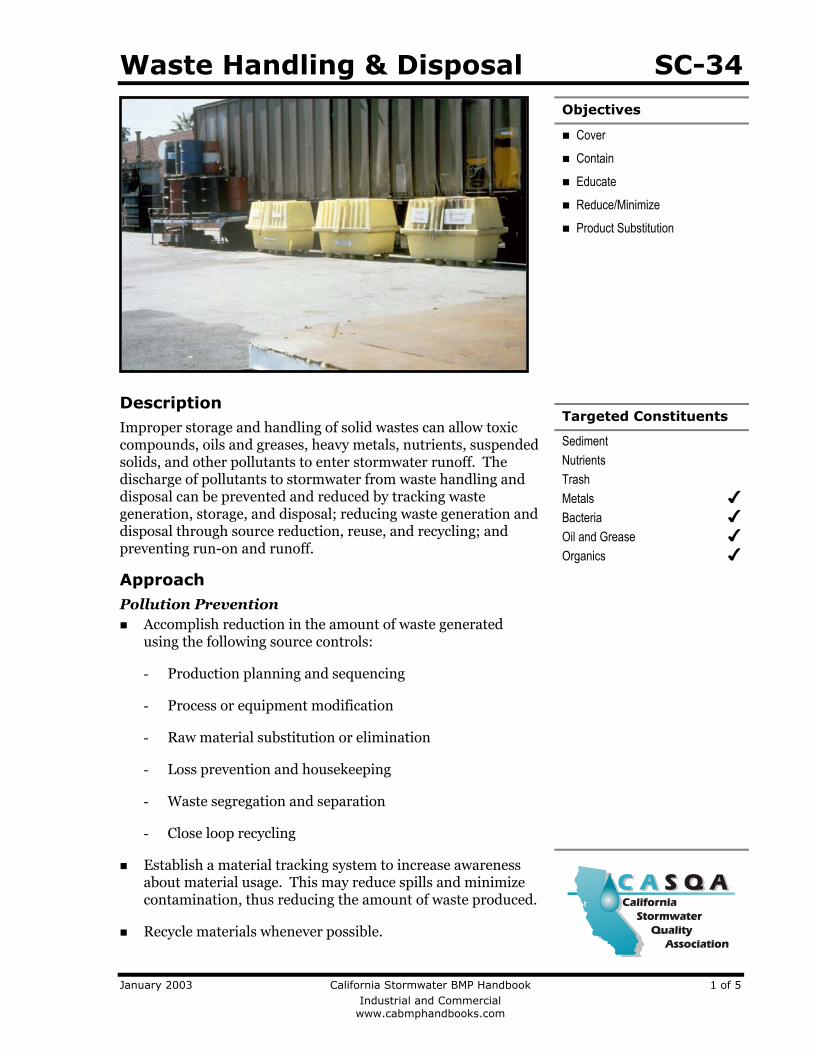
Waste Handling & Disposal SC-34 Objectives
Cover
Contain
Educate
Reduce/Minimize
Product Substitution
Targeted Constituents
Sediment Nutrients Trash Metals Bacteria Oil and Grease Organics
Description Improper storage and handling of solid wastes can allow toxic compounds, oils and greases, heavy metals, nutrients, suspended solids, and other pollutants to enter stormwater runoff. The discharge of pollutants to stormwater from waste handling and disposal can be prevented and reduced by tracking waste generation, storage, and disposal; reducing waste generation and disposal through source reduction, reuse, and recycling; and preventing run-on and runoff.
Approach Pollution Prevention Accomplish reduction in the amount of waste generated
using the following source controls:
- Production planning and sequencing
- Process or equipment modification
- Raw material substitution or elimination
- Loss prevention and housekeeping
- Waste segregation and separation
- Close loop recycling
Establish a material tracking system to increase awareness about material usage. This may reduce spills and minimize contamination, thus reducing the amount of waste produced.
Recycle materials whenever possible.
January 2003 California Stormwater BMP Handbook 1 of 5 Industrial and Commercial www.cabmphandbooks.com
SC-34 Waste Handling & Disposal
Suggested Protocols General Cover storage containers with leak proof lids or some other means. If waste is not in
containers, cover all waste piles (plastic tarps are acceptable coverage) and prevent stormwater run-on and runoff with a berm. The waste containers or piles must be covered except when in use.
Use drip pans or absorbent materials whenever grease containers are emptied by vacuum trucks or other means. Grease cannot be left on the ground. Collected grease must be properly disposed of as garbage.
Check storage containers weekly for leaks and to ensure that lids are on tightly. Replace any that are leaking, corroded, or otherwise deteriorating.
Sweep and clean the storage area regularly. If it is paved, do not hose down the area to a storm drain.
Dispose of rinse and wash water from cleaning waste containers into a sanitary sewer if allowed by the local sewer authority. Do not discharge wash water to the street or storm drain.
Transfer waste from damaged containers into safe containers.
Take special care when loading or unloading wastes to minimize losses. Loading systems can be used to minimize spills and fugitive emission losses such as dust or mist. Vacuum transfer systems can minimize waste loss.
Controlling Litter Post “No Littering” signs and enforce anti-litter laws.
Provide a sufficient number of litter receptacles for the facility.
Clean out and cover litter receptacles frequently to prevent spillage.
Waste Collection Keep waste collection areas clean.
Inspect solid waste containers for structural damage regularly. Repair or replace damaged containers as necessary.
Secure solid waste containers; containers must be closed tightly when not in use.
Do not fill waste containers with washout water or any other liquid.
Ensure that only appropriate solid wastes are added to the solid waste container. Certain wastes such as hazardous wastes, appliances, fluorescent lamps, pesticides, etc., may not be disposed of in solid waste containers (see chemical/ hazardous waste collection section below).
2 of 5 California Stormwater BMP Handbook January 2003 Industrial and Commercial www.cabmphandbooks.com
Waste Handling & Disposal SC-34
Do not mix wastes; this can cause chemical reactions, make recycling impossible, and complicate disposal.
Good Housekeeping Use all of the product before disposing of the container.
Keep the waste management area clean at all times by sweeping and cleaning up spills immediately.
Use dry methods when possible (e.g., sweeping, use of absorbents) when cleaning around restaurant/food handling dumpster areas. If water must be used after sweeping/using absorbents, collect water and discharge through grease interceptor to the sewer.
Chemical/Hazardous Wastes Select designated hazardous waste collection areas on-site.
Store hazardous materials and wastes in covered containers and protect them from vandalism.
Place hazardous waste containers in secondary containment.
Make sure that hazardous waste is collected, removed, and disposed of only at authorized disposal areas.
Stencil or demarcate storm drains on the facility’s property with prohibitive message regarding waste disposal.
Run-on/Runoff Prevention Prevent stormwater run-on from entering the waste management area by enclosing the area
or building a berm around the area.
Prevent waste materials from directly contacting rain.
Cover waste piles with temporary covering material such as reinforced tarpaulin, polyethylene, polyurethane, polypropyleneor hypalon.
Cover the area with a permanent roof if feasible.
Cover dumpsters to prevent rain from washing waste out of holes or cracks in the bottom of the dumpster.
Move the activity indoor after ensuring all safety concerns such as fire hazard and ventilation are addressed.
Inspection Inspect and replace faulty pumps or hoses regularly to minimize the potential of releases and
spills.
Check waste management areas for leaking containers or spills.
January 2003 California Stormwater BMP Handbook 3 of 5 Industrial and Commercial www.cabmphandbooks.com
SC-34 Waste Handling & Disposal
Repair leaking equipment including valves, lines, seals, or pumps promptly.
Training Train staff in pollution prevention measures and proper disposal methods.
Train employees and contractors in proper spill containment and cleanup. The employee should have the tools and knowledge to immediately begin cleaning up a spill should one occur.
Train employees and subcontractors in proper hazardous waste management.
Spill Response and Prevention Keep your Spill Prevention Control and Countermeasure (SPCC) Plan up-to-date.
Have an emergency plan, equipment and trained personnel ready at all times to deal immediately with major spills
Collect all spilled liquids and properly dispose of them.
Store and maintain appropriate spill cleanup materials in a location known to all near the designated wash area.
Ensure that vehicles transporting waste have spill prevention equipment that can prevent spills during transport. Spill prevention equipment includes:
- Vehicles equipped with baffles for liquid waste
- Trucks with sealed gates and spill guards for solid waste
Other Considerations (Limitations and Regulations) Hazardous waste cannot be reused or recycled; it must be disposed of by a licensed hazardous waste hauler.
Requirements Costs Capital and O&M costs for these programs will vary substantially depending on the size of the facility and the types of waste handled. Costs should be low if there is an inventory program in place.
Maintenance None except for maintaining equipment for material tracking program.
Supplemental Information Further Detail of the BMP Land Treatment System Minimize runoff of polluted stormwater from land application by:
Choosing a site where slopes are under 6%, the soil is permeable, there is a low water table, it is located away from wetlands or marshes, and there is a closed drainage system
4 of 5 California Stormwater BMP Handbook January 2003 Industrial and Commercial www.cabmphandbooks.com
Waste Handling & Disposal SC-34
January 2003 California Stormwater BMP Handbook 5 of 5 Industrial and Commercial www.cabmphandbooks.com
Avoiding application of waste to the site when it is raining or when the ground is saturated with water
Growing vegetation on land disposal areas to stabilize soils and reduce the volume of surface water runoff from the site
Maintaining adequate barriers between the land application site and the receiving waters (planted strips are particularly good)
Using erosion control techniques such as mulching and matting, filter fences, straw bales, diversion terracing, and sediment basins
Performing routine maintenance to ensure the erosion control or site stabilization measures are working
Examples The port of Long Beach has a state-of-the-art database for identifying potential pollutant sources, documenting facility management practices, and tracking pollutants.
References and Resources California’s Nonpoint Source Program Plan http://www.swrcb.ca.gov/nps/index.html
Clark County Storm Water Pollution Control Manual http://www.co.clark.wa.us/pubworks/bmpman.pdf
Solid Waste Container Best Management Practices – Fact Sheet On-Line Resources – Environmental Health and Safety. Harvard University. 2002.
King County Storm Water Pollution Control Manual http://dnr.metrokc.gov/wlr/dss/spcm.htm
Pollution from Surface Cleaning Folder. 1996. Bay Area Stormwater Management Agencies Association (BASMAA). http://www.basmaa.org
Santa Clara Valley Urban Runoff Pollution Prevention Program http://www.scvurppp.org
The Storm Water Managers Resource Center http://www.stormwatercenter.net/
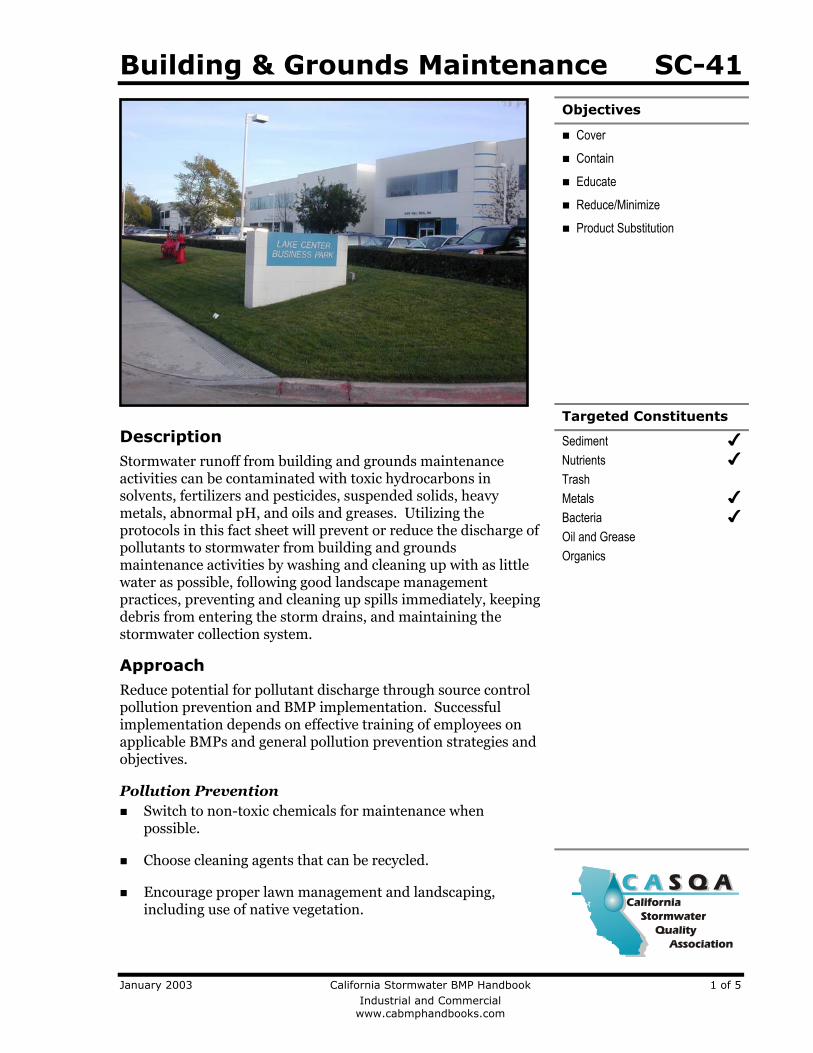
Building & Grounds Maintenance SC-41 Objectives
Cover
Contain
Educate
Reduce/Minimize
Product Substitution
Targeted Constituents
Sediment Nutrients Trash Metals Bacteria Oil and Grease Organics
Description Stormwater runoff from building and grounds maintenance activities can be contaminated with toxic hydrocarbons in solvents, fertilizers and pesticides, suspended solids, heavy metals, abnormal pH, and oils and greases. Utilizing the protocols in this fact sheet will prevent or reduce the discharge of pollutants to stormwater from building and grounds maintenance activities by washing and cleaning up with as little water as possible, following good landscape management practices, preventing and cleaning up spills immediately, keeping debris from entering the storm drains, and maintaining the stormwater collection system.
Approach Reduce potential for pollutant discharge through source control pollution prevention and BMP implementation. Successful implementation depends on effective training of employees on applicable BMPs and general pollution prevention strategies and objectives.
Pollution Prevention Switch to non-toxic chemicals for maintenance when
possible.
Choose cleaning agents that can be recycled.
Encourage proper lawn management and landscaping, including use of native vegetation.
January 2003 California Stormwater BMP Handbook 1 of 5 Industrial and Commercial www.cabmphandbooks.com
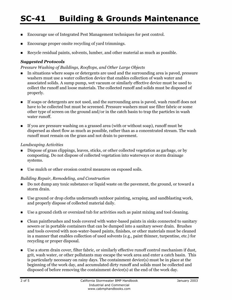
SC-41 Building & Grounds Maintenance
Encourage use of Integrated Pest Management techniques for pest control.
Encourage proper onsite recycling of yard trimmings.
Recycle residual paints, solvents, lumber, and other material as much as possible.
Suggested Protocols Pressure Washing of Buildings, Rooftops, and Other Large Objects In situations where soaps or detergents are used and the surrounding area is paved, pressure
washers must use a water collection device that enables collection of wash water and associated solids. A sump pump, wet vacuum or similarly effective device must be used to collect the runoff and loose materials. The collected runoff and solids must be disposed of properly.
If soaps or detergents are not used, and the surrounding area is paved, wash runoff does not have to be collected but must be screened. Pressure washers must use filter fabric or some other type of screen on the ground and/or in the catch basin to trap the particles in wash water runoff.
If you are pressure washing on a grassed area (with or without soap), runoff must be dispersed as sheet flow as much as possible, rather than as a concentrated stream. The wash runoff must remain on the grass and not drain to pavement.
Landscaping Activities Dispose of grass clippings, leaves, sticks, or other collected vegetation as garbage, or by
composting. Do not dispose of collected vegetation into waterways or storm drainage systems.
Use mulch or other erosion control measures on exposed soils.
Building Repair, Remodeling, and Construction Do not dump any toxic substance or liquid waste on the pavement, the ground, or toward a
storm drain.
Use ground or drop cloths underneath outdoor painting, scraping, and sandblasting work, and properly dispose of collected material daily.
Use a ground cloth or oversized tub for activities such as paint mixing and tool cleaning.
Clean paintbrushes and tools covered with water-based paints in sinks connected to sanitary sewers or in portable containers that can be dumped into a sanitary sewer drain. Brushes and tools covered with non-water-based paints, finishes, or other materials must be cleaned in a manner that enables collection of used solvents (e.g., paint thinner, turpentine, etc.) for recycling or proper disposal.
Use a storm drain cover, filter fabric, or similarly effective runoff control mechanism if dust, grit, wash water, or other pollutants may escape the work area and enter a catch basin. This is particularly necessary on rainy days. The containment device(s) must be in place at the beginning of the work day, and accumulated dirty runoff and solids must be collected and disposed of before removing the containment device(s) at the end of the work day.
2 of 5 California Stormwater BMP Handbook January 2003 Industrial and Commercial www.cabmphandbooks.com
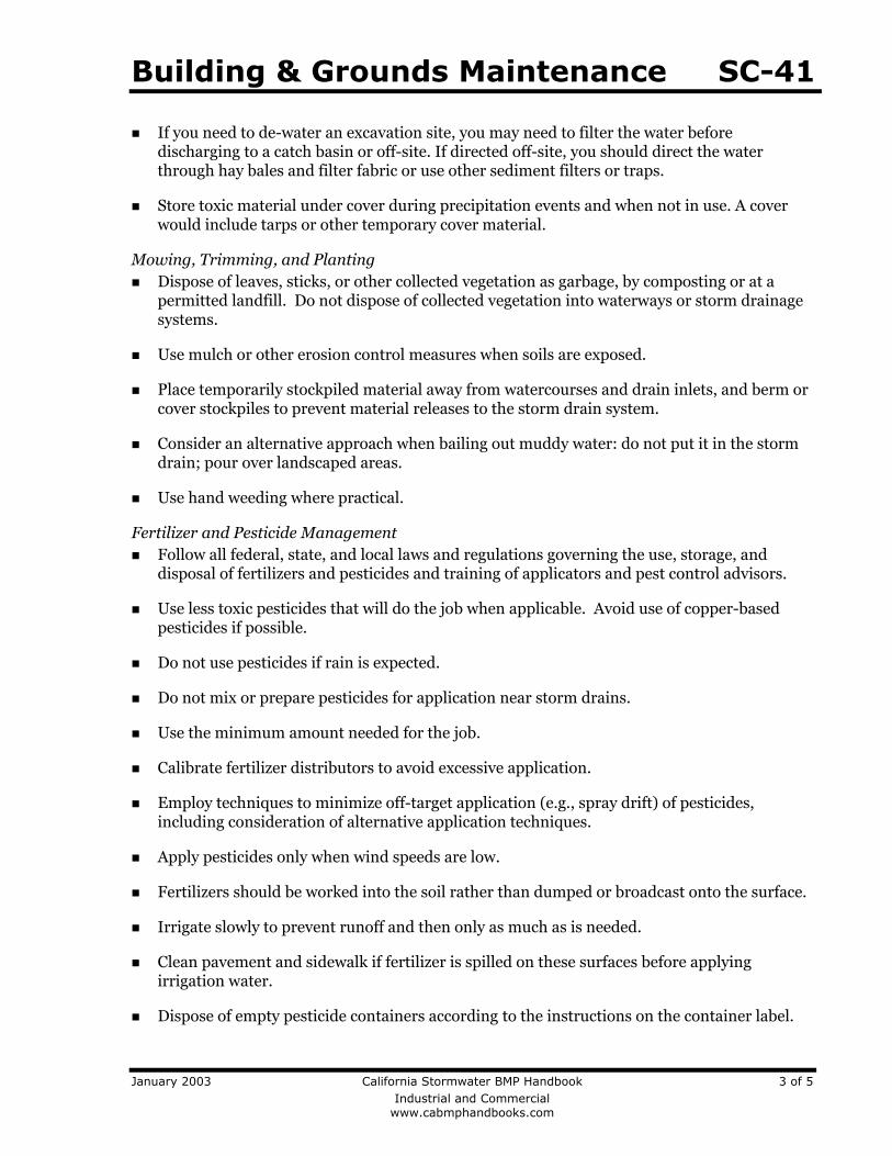
Building & Grounds Maintenance SC-41
If you need to de-water an excavation site, you may need to filter the water before discharging to a catch basin or off-site. If directed off-site, you should direct the water through hay bales and filter fabric or use other sediment filters or traps.
Store toxic material under cover during precipitation events and when not in use. A cover would include tarps or other temporary cover material.
Mowing, Trimming, and Planting Dispose of leaves, sticks, or other collected vegetation as garbage, by composting or at a
permitted landfill. Do not dispose of collected vegetation into waterways or storm drainage systems.
Use mulch or other erosion control measures when soils are exposed.
Place temporarily stockpiled material away from watercourses and drain inlets, and berm or cover stockpiles to prevent material releases to the storm drain system.
Consider an alternative approach when bailing out muddy water: do not put it in the storm drain; pour over landscaped areas.
Use hand weeding where practical.
Fertilizer and Pesticide Management Follow all federal, state, and local laws and regulations governing the use, storage, and
disposal of fertilizers and pesticides and training of applicators and pest control advisors.
Use less toxic pesticides that will do the job when applicable. Avoid use of copper-based pesticides if possible.
Do not use pesticides if rain is expected.
Do not mix or prepare pesticides for application near storm drains.
Use the minimum amount needed for the job.
Calibrate fertilizer distributors to avoid excessive application.
Employ techniques to minimize off-target application (e.g., spray drift) of pesticides, including consideration of alternative application techniques.
Apply pesticides only when wind speeds are low.
Fertilizers should be worked into the soil rather than dumped or broadcast onto the surface.
Irrigate slowly to prevent runoff and then only as much as is needed.
Clean pavement and sidewalk if fertilizer is spilled on these surfaces before applying irrigation water.
Dispose of empty pesticide containers according to the instructions on the container label.
January 2003 California Stormwater BMP Handbook 3 of 5 Industrial and Commercial www.cabmphandbooks.com
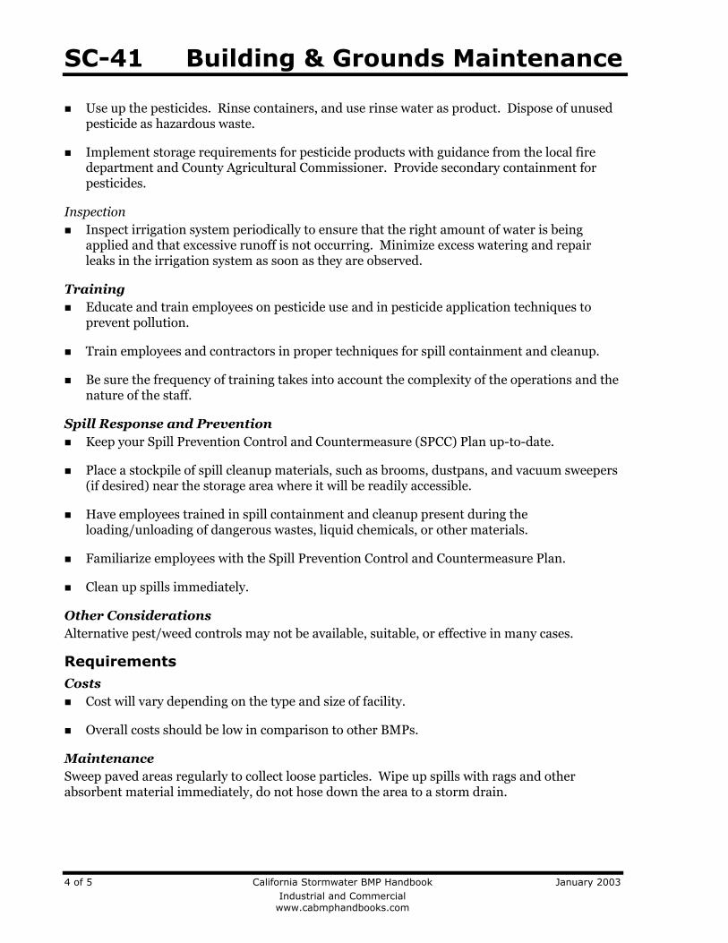
SC-41 Building & Grounds Maintenance
Use up the pesticides. Rinse containers, and use rinse water as product. Dispose of unused pesticide as hazardous waste.
Implement storage requirements for pesticide products with guidance from the local fire department and County Agricultural Commissioner. Provide secondary containment for pesticides.
Inspection Inspect irrigation system periodically to ensure that the right amount of water is being
applied and that excessive runoff is not occurring. Minimize excess watering and repair leaks in the irrigation system as soon as they are observed.
Training Educate and train employees on pesticide use and in pesticide application techniques to
prevent pollution.
Train employees and contractors in proper techniques for spill containment and cleanup.
Be sure the frequency of training takes into account the complexity of the operations and the nature of the staff.
Spill Response and Prevention Keep your Spill Prevention Control and Countermeasure (SPCC) Plan up-to-date.
Place a stockpile of spill cleanup materials, such as brooms, dustpans, and vacuum sweepers (if desired) near the storage area where it will be readily accessible.
Have employees trained in spill containment and cleanup present during the loading/unloading of dangerous wastes, liquid chemicals, or other materials.
Familiarize employees with the Spill Prevention Control and Countermeasure Plan.
Clean up spills immediately.
Other Considerations Alternative pest/weed controls may not be available, suitable, or effective in many cases.
Requirements Costs Cost will vary depending on the type and size of facility.
Overall costs should be low in comparison to other BMPs.
Maintenance Sweep paved areas regularly to collect loose particles. Wipe up spills with rags and other absorbent material immediately, do not hose down the area to a storm drain.
4 of 5 California Stormwater BMP Handbook January 2003 Industrial and Commercial www.cabmphandbooks.com
Building & Grounds Maintenance SC-41
January 2003 California Stormwater BMP Handbook 5 of 5 Industrial and Commercial www.cabmphandbooks.com
Supplemental Information Further Detail of the BMP Fire Sprinkler Line Flushing Building fire sprinkler line flushing may be a source of non-stormwater runoff pollution. The water entering the system is usually potable water, though in some areas it may be non-potable reclaimed wastewater. There are subsequent factors that may drastically reduce the quality of the water in such systems. Black iron pipe is usually used since it is cheaper than potable piping, but it is subject to rusting and results in lower quality water. Initially, the black iron pipe has an oil coating to protect it from rusting between manufacture and installation; this will contaminate the water from the first flush but not from subsequent flushes. Nitrates, poly-phosphates and other corrosion inhibitors, as well as fire suppressants and antifreeze may be added to the sprinkler water system. Water generally remains in the sprinkler system a long time (typically a year) and between flushes may accumulate iron, manganese, lead, copper, nickel, and zinc. The water generally becomes anoxic and contains living and dead bacteria and breakdown products from chlorination. This may result in a significant BOD problem and the water often smells. Consequently dispose fire sprinkler line flush water into the sanitary sewer. Do not allow discharge to storm drain or infiltration due to potential high levels of pollutants in fire sprinkler line water.
References and Resources California’s Nonpoint Source Program Plan http://www.swrcb.ca.gov/nps/index.html
Clark County Storm Water Pollution Control Manual http://www.co.clark.wa.us/pubworks/bmpman.pdf
King County Storm Water Pollution Control Manual http://dnr.metrokc.gov/wlr/dss/spcm.htm
Mobile Cleaners Pilot Program: Final Report. 1997. Bay Area Stormwater Management Agencies Association (BASMAA). http://www.basmaa.org/
Pollution from Surface Cleaning Folder. 1996. Bay Area Stormwater Management Agencies Association (BASMAA). http://www.basmaa.org/
Santa Clara Valley Urban Runoff Pollution Prevention Program http://www.scvurppp.org
The Storm Water Managers Resource Center http://www.stormwatercenter.net/
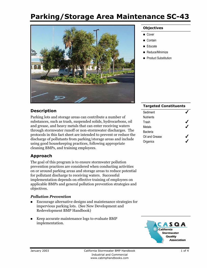
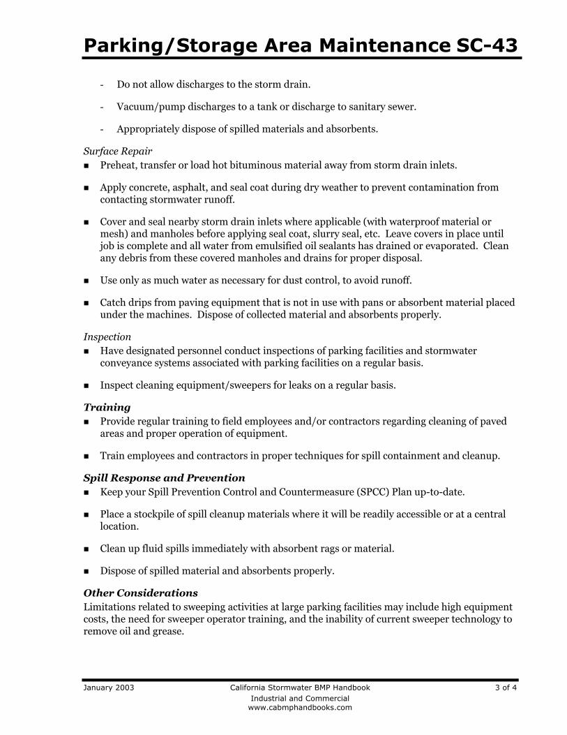
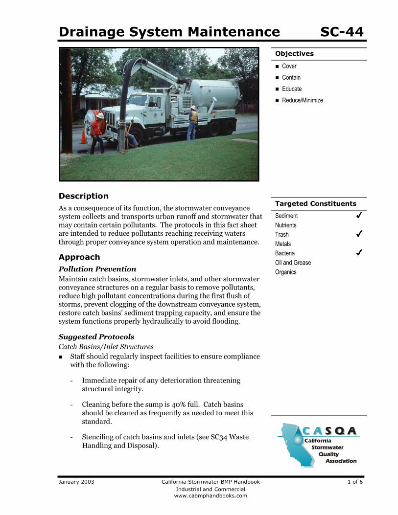
Drainage System Maintenance SC-44Objectives
Cover
Contain
Educate
Reduce/Minimize
Targeted Constituents
SedimentNutrientsTrashMetalsBacteriaOil and GreaseOrganics
DescriptionAs a consequence of its function, the stormwater conveyancesystem collects and transports urban runoff and stormwater thatmay contain certain pollutants. The protocols in this fact sheetare intended to reduce pollutants reaching receiving watersthrough proper conveyance system operation and maintenance.
ApproachPollution PreventionMaintain catch basins, stormwater inlets, and other stormwaterconveyance structures on a regular basis to remove pollutants,reduce high pollutant concentrations during the first flush ofstorms, prevent clogging of the downstream conveyance system,restore catch basins’ sediment trapping capacity, and ensure thesystem functions properly hydraulically to avoid flooding.
Suggested ProtocolsCatch Basins/Inlet Structures
Staff should regularly inspect facilities to ensure compliancewith the following:
- Immediate repair of any deterioration threateningstructural integrity.
- Cleaning before the sump is 40% full. Catch basinsshould be cleaned as frequently as needed to meet thisstandard.
- Stenciling of catch basins and inlets (see SC34 WasteHandling and Disposal).
January 2003 California Stormwater BMP Handbook 1 of 6 Industrial and Commercial www.cabmphandbooks.com
SC-44 Drainage System Maintenance
Clean catch basins, storm drain inlets, and other conveyance structures before the wetseason to remove sediments and debris accumulated during the summer.
Conduct inspections more frequently during the wet season for problem areas wheresediment or trash accumulates more often. Clean and repair as needed.
Keep accurate logs of the number of catch basins cleaned.
Store wastes collected from cleaning activities of the drainage system in appropriatecontainers or temporary storage sites in a manner that prevents discharge to the stormdrain.
Dewater the wastes if necessary with outflow into the sanitary sewer if permitted. Watershould be treated with an appropriate filtering device prior to discharge to the sanitarysewer. If discharge to the sanitary sewer is not allowed, water should be pumped orvacuumed to a tank and properly disposed. Do not dewater near a storm drain or stream.
Storm Drain Conveyance SystemLocate reaches of storm drain with deposit problems and develop a flushing schedule thatkeeps the pipe clear of excessive buildup.
Collect and pump flushed effluent to the sanitary sewer for treatment whenever possible.
Pump StationsClean all storm drain pump stations prior to the wet season to remove silt and trash.
Do not allow discharge to reach the storm drain system when cleaning a storm drain pumpstation or other facility.
Conduct routine maintenance at each pump station.
Inspect, clean, and repair as necessary all outlet structures prior to the wet season.
Open ChannelModify storm channel characteristics to improve channel hydraulics, increase pollutantremovals, and enhance channel/creek aesthetic and habitat value.
Conduct channel modification/improvement in accordance with existing laws. Any person,government agency, or public utility proposing an activity that will change the natural(emphasis added) state of any river, stream, or lake in California, must enter into a Steam orLake Alteration Agreement with the Department of Fish and Game. The developer-applicantshould also contact local governments (city, county, special districts), other state agencies(SWRCB, RWQCB, Department of Forestry, Department of Water Resources), and FederalCorps of Engineers and USFWS.
Illicit Connections and DischargesLook for evidence of illegal discharges or illicit connections during routine maintenance ofconveyance system and drainage structures:
- Is there evidence of spills such as paints, discoloring, etc?
2 of 6 California Stormwater BMP Handbook January 2003 Industrial and Commercial www.cabmphandbooks.com
Drainage System Maintenance SC-44
- Are there any odors associated with the drainage system?
- Record locations of apparent illegal discharges/illicit connections?
- Track flows back to potential dischargers and conduct aboveground inspections. Thiscan be done through visual inspection of upgradient manholes or alternate techniquesincluding zinc chloride smoke testing, fluorometric dye testing, physical inspectiontesting, or television camera inspection.
- Eliminate the discharge once the origin of flow is established.
Stencil or demarcate storm drains, where applicable, to prevent illegal disposal of pollutants.Storm drain inlets should have messages such as “Dump No Waste Drains to Stream”stenciled next to them to warn against ignorant or intentional dumping of pollutants into thestorm drainage system.
Refer to fact sheet SC-10 Non-Stormwater Discharges.
Illegal DumpingInspect and clean up hot spots and other storm drainage areas regularly where illegaldumping and disposal occurs.
Establish a system for tracking incidents. The system should be designed to identify thefollowing:
- Illegal dumping hot spots
- Types and quantities (in some cases) of wastes
- Patterns in time of occurrence (time of day/night, month, or year)
- Mode of dumping (abandoned containers, “midnight dumping” from moving vehicles,direct dumping of materials, accidents/spills)
- Responsible parties
Post “No Dumping” signs in problem areas with a phone number for reporting dumping anddisposal. Signs should also indicate fines and penalties for illegal dumping.
Refer to fact sheet SC-10 Non-Stormwater Discharges.
TrainingTrain crews in proper maintenance activities, including record keeping and disposal.
Allow only properly trained individuals to handle hazardous materials/wastes.
Have staff involved in detection and removal of illicit connections trained in the following:
- OSHA-required Health and Safety Training (29 CFR 1910.120) plus annual refreshertraining (as needed).
January 2003 California Stormwater BMP Handbook 3 of 6 Industrial and Commercial www.cabmphandbooks.com
SC-44 Drainage System Maintenance
- OSHA Confined Space Entry training (Cal-OSHA Confined Space, Title 8 and FederalOSHA 29 CFR 1910.146).
- Procedural training (field screening, sampling, smoke/dye testing, TV inspection).
Spill Response and PreventionInvestigate all reports of spills, leaks, and/or illegal dumping promptly.
Clean up all spills and leaks using “dry” methods (with absorbent materials and/or rags) ordig up, remove, and properly dispose of contaminated soil.
Refer to fact sheet SC-11 Spill Prevention, Control, and Cleanup.
Other Considerations (Limitations and Regulations)Clean-up activities may create a slight disturbance for local aquatic species. Access to itemsand material on private property may be limited. Trade-offs may exist between channelhydraulics and water quality/riparian habitat. If storm channels or basins are recognized aswetlands, many activities, including maintenance, may be subject to regulation andpermitting.
Storm drain flushing is most effective in small diameter pipes (36-inch diameter pipe or less,depending on water supply and sediment collection capacity). Other considerationsassociated with storm drain flushing may include the availability of a water source, finding adownstream area to collect sediments, liquid/sediment disposal, and prohibition againstdisposal of flushed effluent to sanitary sewer in some areas.
Regulations may include adoption of substantial penalties for illegal dumping and disposal.
Local municipal codes may include sections prohibiting discharge of soil, debris, refuse,hazardous wastes, and other pollutants into the storm drain system.
RequirementsCosts
An aggressive catch basin cleaning program could require a significant capital and O&Mbudget.
The elimination of illegal dumping is dependent on the availability, convenience, and cost ofalternative means of disposal. The primary cost is for staff time. Cost depends on howaggressively a program is implemented. Other cost considerations for an illegal dumpingprogram include:
- Purchase and installation of signs.
- Rental of vehicle(s) to haul illegally-disposed items and material to landfills.
- Rental of heavy equipment to remove larger items (e.g., car bodies) from channels.
- Purchase of landfill space to dispose of illegally-dumped items and material.
4 of 6 California Stormwater BMP Handbook January 2003 Industrial and Commercial www.cabmphandbooks.com
Drainage System Maintenance SC-44
Methods used for illicit connection detection (smoke testing, dye testing, visual inspection,and flow monitoring) can be costly and time-consuming. Site-specific factors, such as thelevel of impervious area, the density and ages of buildings, and type of land use willdetermine the level of investigation necessary.
MaintenanceTwo-person teams may be required to clean catch basins with vactor trucks.
Teams of at least two people plus administrative personnel are required to identify illicitdischarges, depending on the complexity of the storm sewer system.
Arrangements must be made for proper disposal of collected wastes.
Technical staff are required to detect and investigate illegal dumping violations.
Supplemental InformationFurther Detail of the BMPStorm Drain FlushingFlushing is a common maintenance activity used to improve pipe hydraulics and to removepollutants in storm drainage systems. Flushing may be designed to hydraulically conveyaccumulated material to strategic locations, such as an open channel, another point whereflushing will be initiated, or the sanitary sewer and the treatment facilities, thus preventingresuspension and overflow of a portion of the solids during storm events. Flushing prevents“plug flow” discharges of concentrated pollutant loadings and sediments. Deposits can hinderthe designed conveyance capacity of the storm drain system and potentially cause backwaterconditions in severe cases of clogging.
Storm drain flushing usually takes place along segments of pipe with grades that are too flat tomaintain adequate velocity to keep particles in suspension. An upstream manhole is selected toplace an inflatable device that temporarily plugs the pipe. Further upstream, water is pumpedinto the line to create a flushing wave. When the upstream reach of pipe is sufficiently full tocause a flushing wave, the inflated device is rapidly deflated with the assistance of a vacuumpump, thereby releasing the backed up water and resulting in the cleaning of the storm drainsegment.
To further reduce impacts of stormwater pollution, a second inflatable device placed welldownstream may be used to recollect the water after the force of the flushing wave hasdissipated. A pump may then be used to transfer the water and accumulated material to thesanitary sewer for treatment. In some cases, an interceptor structure may be more practical orrequired to recollect the flushed waters.
It has been found that cleansing efficiency of periodic flush waves is dependent upon flushvolume, flush discharge rate, sewer slope, sewer length, sewer flow rate, sewer diameter, andpopulation density. As a rule of thumb, the length of line to be flushed should not exceed 700feet. At this maximum recommended length, the percent removal efficiency ranges between 65-75% for organics and 55-65% for dry weather grit/inorganic material. The percent removalefficiency drops rapidly beyond that. Water is commonly supplied by a water truck, but firehydrants can also supply water. To make the best use of water, it is recommended thatreclaimed water be used or that fire hydrant line flushing coincide with storm sewer flushing.
January 2003 California Stormwater BMP Handbook 5 of 6 Industrial and Commercial www.cabmphandbooks.com
SC-44 Drainage System Maintenance
6 of 6 California Stormwater BMP Handbook January 2003 Industrial and Commercial www.cabmphandbooks.com
References and ResourcesCalifornia’s Nonpoint Source Program Plan http://www.swrcb.ca.gov/nps/index.html
Clark County Storm Water Pollution Control Manualhttp://www.co.clark.wa.us/pubworks/bmpman.pdf
Ferguson, B.K. 1991. Urban Stream Reclamation, p. 324-322, Journal of Soil and WaterConservation.
King County Storm Water Pollution Control Manual http://dnr.metrokc.gov/wlr/dss/spcm.htm
Oregon Association of Clean Water Agencies. Oregon Municipal Stormwater Toolbox forMaintenance Practices. June 1998.
Santa Clara Valley Urban Runoff Pollution Prevention Program http://www.scvurppp.org
The Storm Water Managers Resource Center http://www.stormwatercenter.net
United States Environmental Protection Agency (USEPA). 2002. Pollution Prevention/GoodHousekeeping for Municipal Operations Storm Drain System Cleaning. On line:http://www.epa.gov/npdes/menuofbmps/poll_16.htm
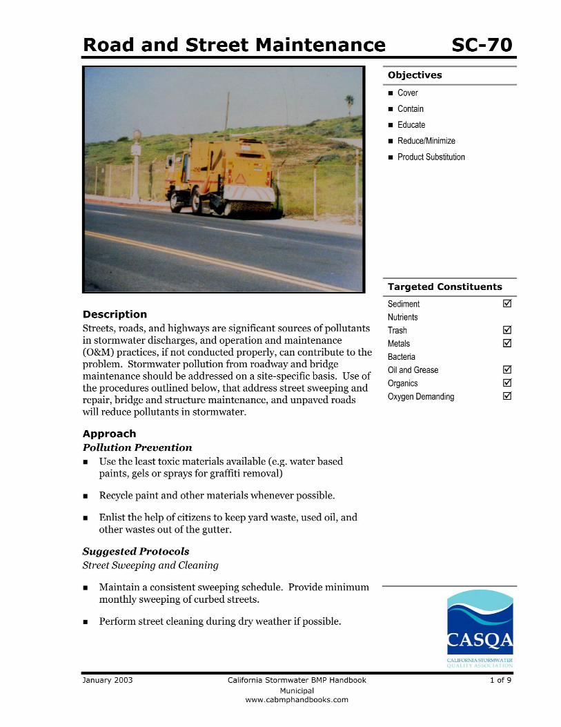

Efficient Irrigation SD-12
January 2003 California Stormwater BMP Handbook 1 of 2 New Development and Redevelopment www.cabmphandbooks.com
Description Irrigation water provided to landscaped areas may result in excess irrigation water being conveyed into stormwater drainage systems.
Approach Project plan designs for development and redevelopment should include application methods of irrigation water that minimize runoff of excess irrigation water into the stormwater conveyance system.
Suitable Applications Appropriate applications include residential, commercial and industrial areas planned for development or redevelopment. (Detached residential single-family homes are typically excluded from this requirement.)
Design Considerations Designing New Installations The following methods to reduce excessive irrigation runoff should be considered, and incorporated and implemented where determined applicable and feasible by the Permittee:
Employ rain-triggered shutoff devices to prevent irrigation after precipitation.
Design irrigation systems to each landscape area’s specific water requirements.
Include design featuring flow reducers or shutoff valves triggered by a pressure drop to control water loss in the event of broken sprinkler heads or lines.
Implement landscape plans consistent with County or City water conservation resolutions, which may include provision of water sensors, programmable irrigation times (for short cycles), etc.
Design Objectives
Maximize Infiltration
Provide Retention
Slow Runoff
Minimize Impervious Land Coverage
Prohibit Dumping of Improper Materials
Contain Pollutants
Collect and Convey
SD-12 Efficient Irrigation
2 of 2 California Stormwater BMP Handbook January 2003 New Development and Redevelopment www.cabmphandbooks.com
Design timing and application methods of irrigation water to minimize the runoff of excess irrigation water into the storm water drainage system.
Group plants with similar water requirements in order to reduce excess irrigation runoff and promote surface filtration. Choose plants with low irrigation requirements (for example, native or drought tolerant species). Consider design features such as:
- Using mulches (such as wood chips or bar) in planter areas without ground cover to minimize sediment in runoff
- Installing appropriate plant materials for the location, in accordance with amount of sunlight and climate, and use native plant materials where possible and/or as recommended by the landscape architect
- Leaving a vegetative barrier along the property boundary and interior watercourses, to act as a pollutant filter, where appropriate and feasible
- Choosing plants that minimize or eliminate the use of fertilizer or pesticides to sustain growth
Employ other comparable, equally effective methods to reduce irrigation water runoff.
Redeveloping Existing Installations Various jurisdictional stormwater management and mitigation plans (SUSMP, WQMP, etc.) define “redevelopment” in terms of amounts of additional impervious area, increases in gross floor area and/or exterior construction, and land disturbing activities with structural or impervious surfaces. The definition of “ redevelopment” must be consulted to determine whether or not the requirements for new development apply to areas intended for redevelopment. If the definition applies, the steps outlined under “designing new installations” above should be followed.
Other Resources A Manual for the Standard Urban Stormwater Mitigation Plan (SUSMP), Los Angeles County Department of Public Works, May 2002.
Model Standard Urban Storm Water Mitigation Plan (SUSMP) for San Diego County, Port of San Diego, and Cities in San Diego County, February 14, 2002.
Model Water Quality Management Plan (WQMP) for County of Orange, Orange County Flood Control District, and the Incorporated Cities of Orange County, Draft February 2003.
Ventura Countywide Technical Guidance Manual for Stormwater Quality Control Measures, July 2002.
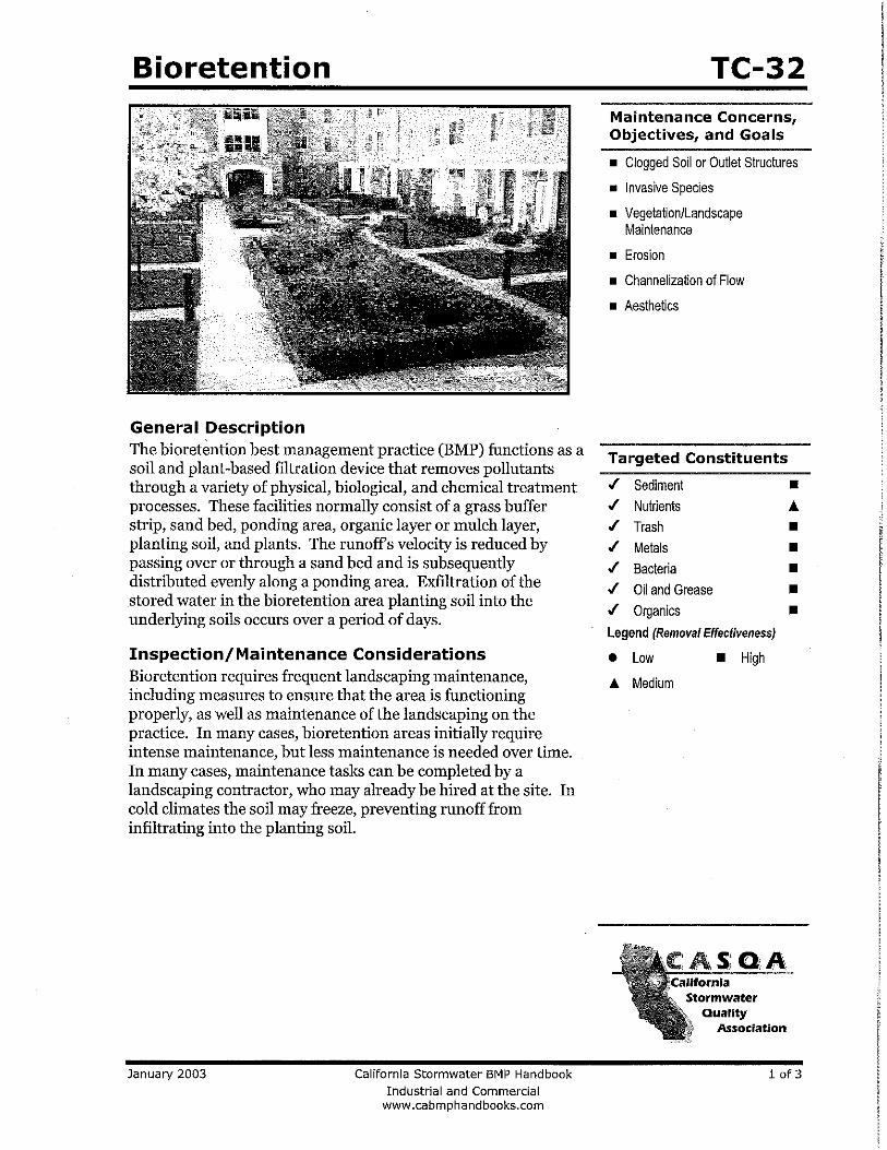
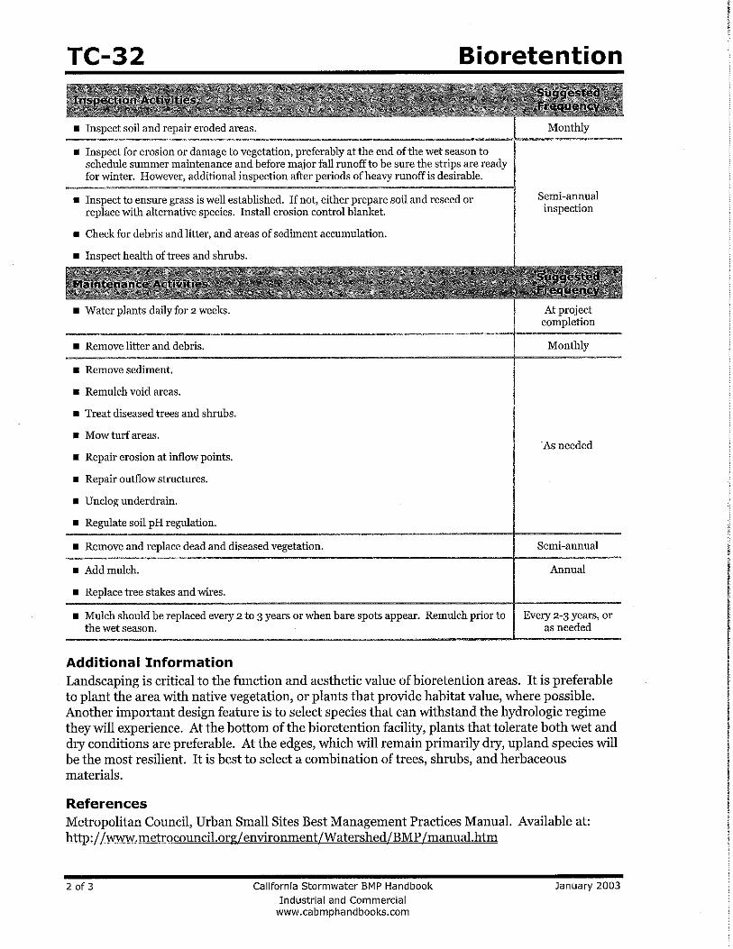
ATTACHMENT G
CONCEPTUAL WQMP SITE PLAN
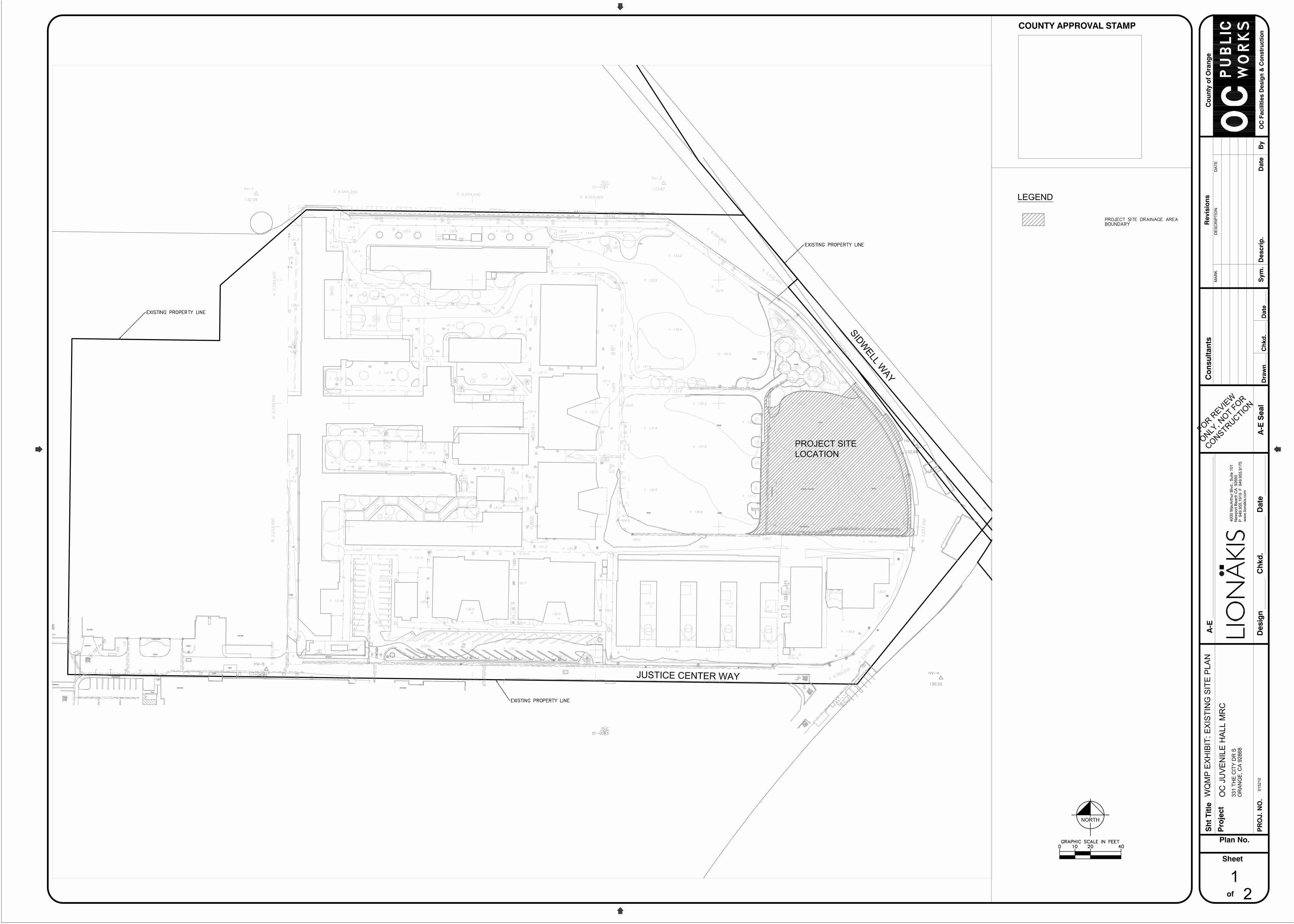
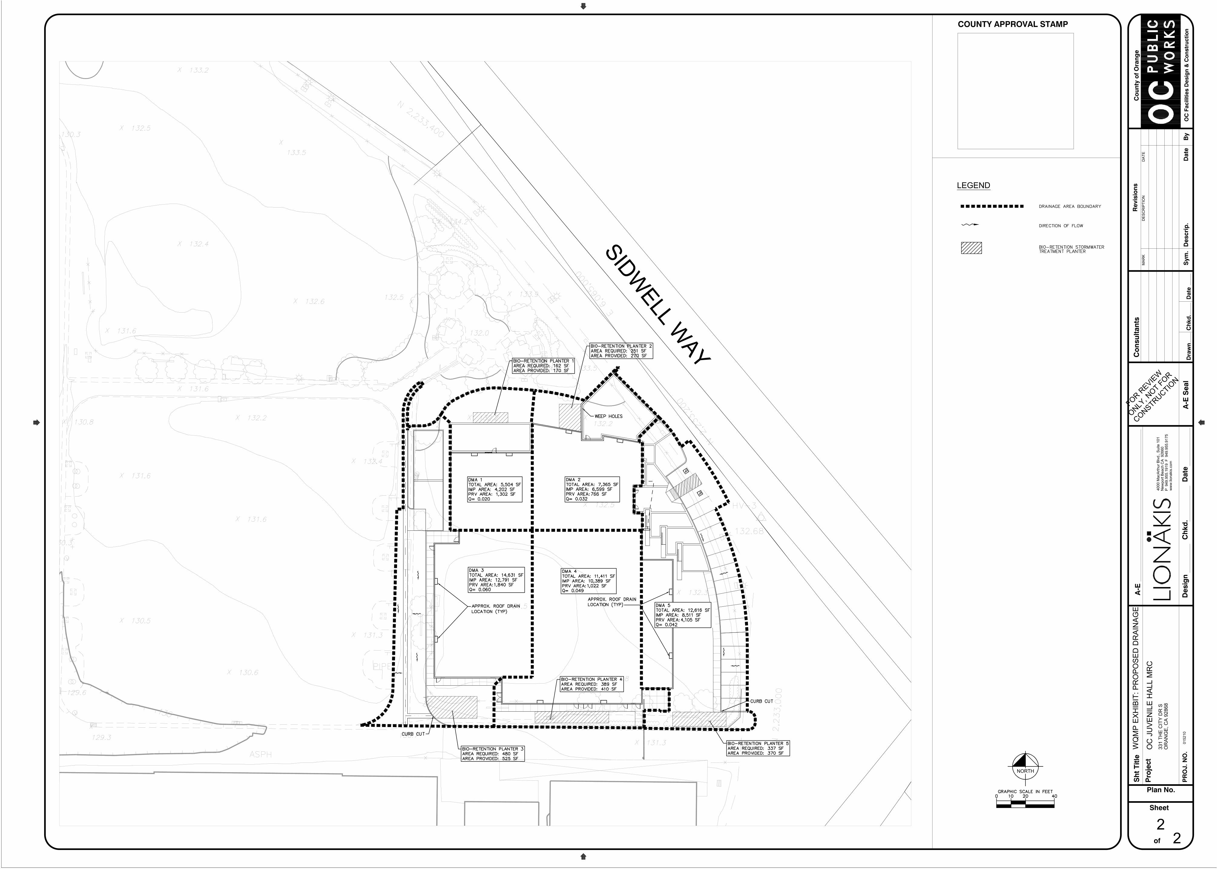
ATTACHMENT H
TRANSFER OF RESPONSIBILITY


