Embed Size (px)
Citation preview
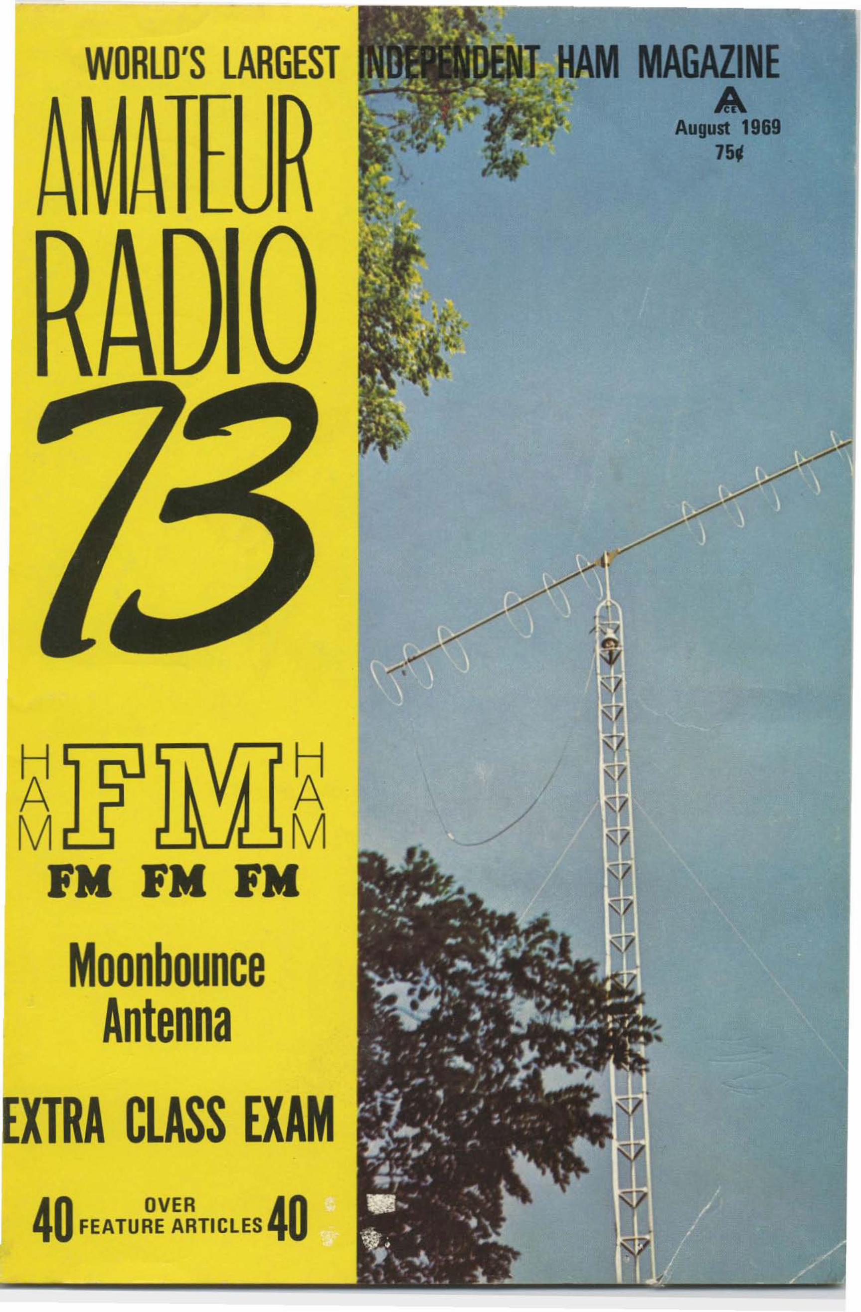
WORLD'S LARGEST
40 FEATU~:~~TICLES 40
~ ~M M /
PM PM PM
MoonbounceAntenna
EXTRA CLASS EXAM
.- ::::::
e-- •• .--
~"••- ••
e ' ., -
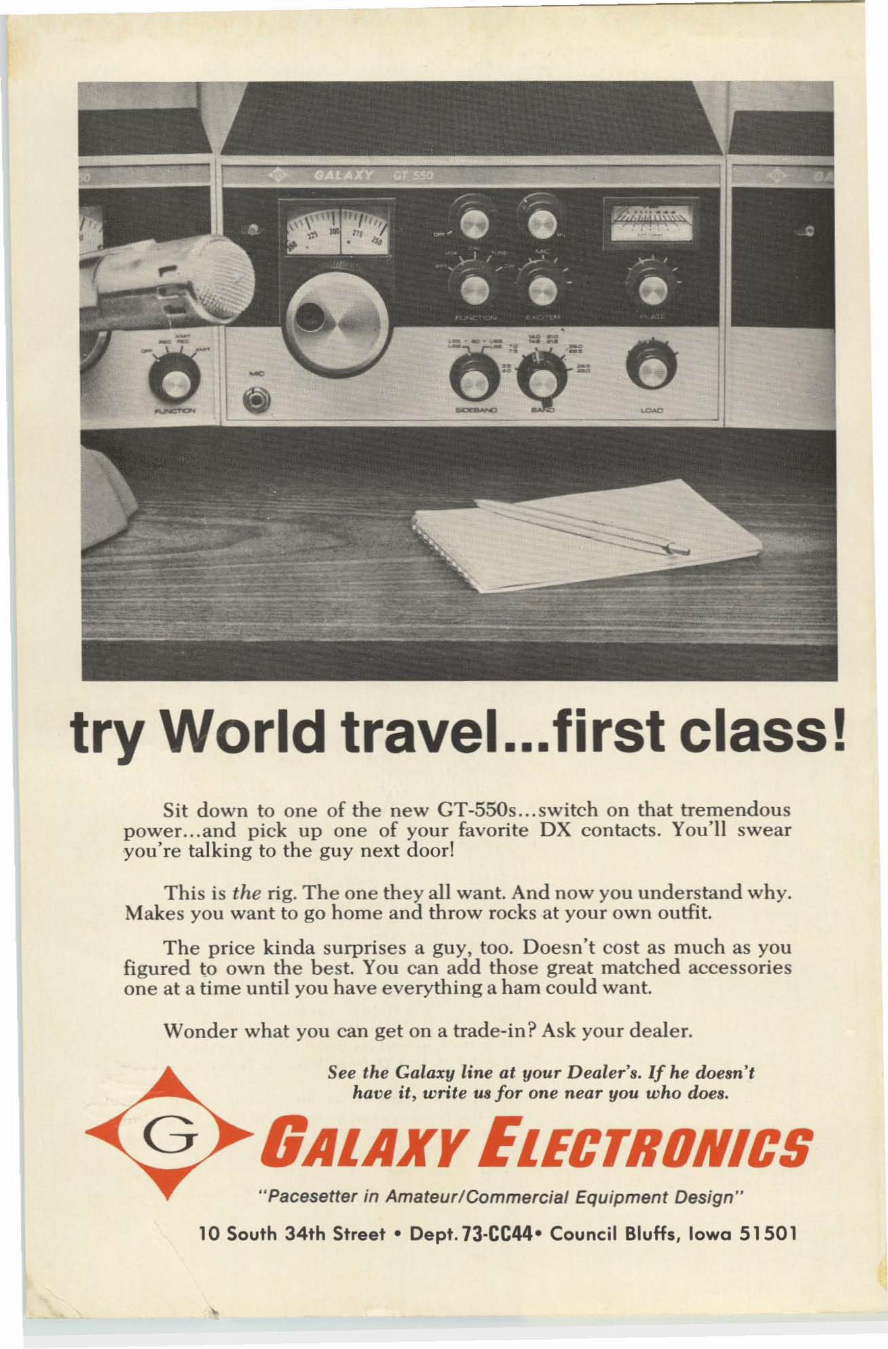
try World travel ...first class!Sit down to one of the new GT-550s ... sw itch on that tremendous
power. .. and pick up one of your favorite OX contacts. You'll swearyou're talking to the guy next door!
This is the rig. The one they all want. And now you understand why.Make s you want to go home and throw rocks at your own outfit.
The price kinda surprises a guy, too. Doesn't cost as much as youfigured to ow n the be st. You can add those great matched accessoriesone at a time until you have everyth ing a ham could want.
Wonder what you can get on a trade-in? Ask your dealer.
See the Galaxy line at your Dealer's. If he doesn'thave it, write U8 for one near you who does.
GALAXY ELECTRONICS"Pacesetter in Amateur/Commercial Equipment Design"
10 South 34th Street· Dept. 73·CC44· Council Bluffs, Iowa 51501
MAGAZINE
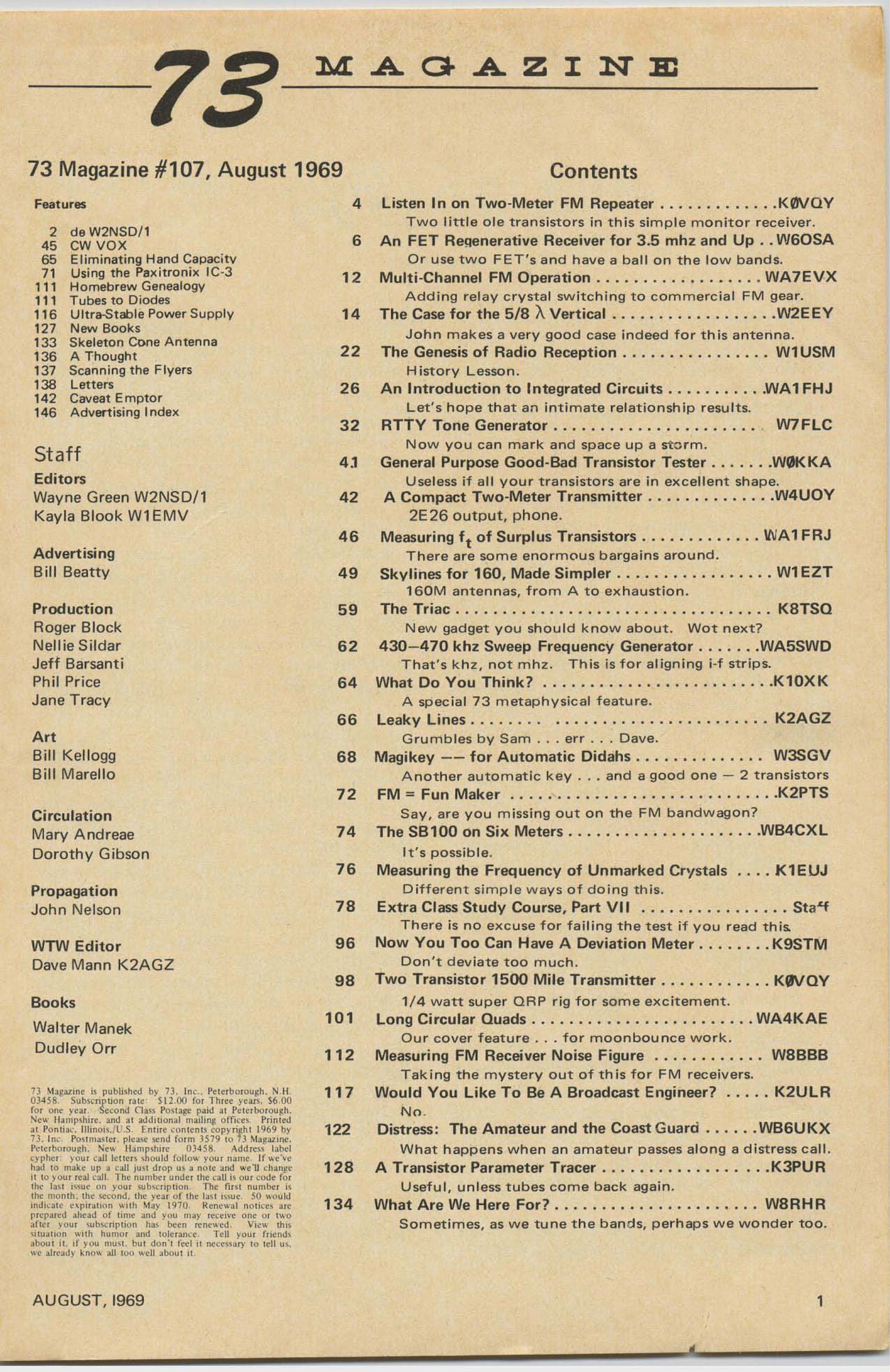
73 Magazine #107, August 1969 ContentsFeatures
2 de W2N$D/145 CW VOX65 Eliminat ing Hand Capacity7 1 Using the Paxitro nix IC-3
111 Hom ebrew Genealogy111 Tubes to Diodes11 6 Ultra-Stable Power Su pply127 New Books133 Skeleton Gone Anten na136 A Thought137 Scanning the Flyers138 Letters142 Caveat Emptor146 Advert ising Index
StaffEditorsWay ne Green W2NSD/ lKayla Bloo k Wl EMV
AdvertisingBil l Beatty
ProductionRoger BlockNellie SildarJeff BarsantiPh il PriceJane Tracy
ArtBill Ke lloggBill Marella
CirculationMary And reaeDorothy G ibson
PropagationJoh n Nelson
WTW EditorDave Mann K2AGZ
Books
Walter ManekDudley O rr
73 ~h~",)n . is publi'hed by 73. Inc .. P'I.rborQ u~h. N HO J4 S ~ . Sub,rnpllon W e S12,OU for lhrre ye"". $6 .00fOf one year . Second Cl." Po,lat" paid al Pelerbo,ou~h.~ew Il.mp,hife. and 01 addll ional maili n~ ofro,·e' . P,ioledal Ponli••·. Il l i no;' .~ U .S , ~.nli,e "oolenl, COp}'li~h l 1969 byn . In•. PO'lm."e,. pic... ,,",od fo,m JS79 10 H .\b~all"".Pele,b",ou~ h, "ew lIanlp<hi,. 03458 Add,es< label"yphe' ~'our call Ielle" ,hould fulluw you, o.me. If ""C',"had '0 make up • ( all ju" drop uS • oOlc >od "'oU ,·h.n~c
il 10 yum ,cal ,·all. Tho numbe, "nde, Ihe ,caU;. ou, rode fo,til<' la" i"ue nn you, 'Ub""pllun, The fir- I numb., i.ll,e monlh . lI,e ,",ooJ. lhe ye., "f lho 1><1 i"ue. 50 "'''uk!iod i,·. , e .-pi,,,-won Wllh Mal-' 1970. R. ne",al nOli,'" ...prep.red ,head of 'im••nd you m.y 'e'C"ve o n" or Iwo• flt" your ,ub'<:riplroo h.., beeo reoe",ed. View' 11m, itu.""n with humo, .nd lnle,,,,,,," , Tell your frrend,aboul il. tf you nro" , hu ! don'! feel il o",'e"",l-' '0 Id l U< ,we . I,.,dy koo" all 100 " 'eil ,boul il
A UGUST, 1969
4 Listen In on Two-Meter FM Repeater K0VQYTwo littl e o le transist ors in th is simple mo nito r receiver .
6 An FET Heqenerative Receiver for 3 .5 mhz and Up .. W60SAOr use two FET 's a nd have a ba ll o n the lo w bands.
12 Multi-Channel FM Operation WA7EVXAddi ng rel ay crystal switching to commercia l FM gea r.
14 The Case for the 5/8 XVertical W2EEYJohn makes a very good case indeed for t hi s antenna.
22 The Genesis of Radio Reception Wl USMHistory Lesson .
26 An Introduction to Integrated Circuits WAl FHJLet's hope that an intimate relationshi p res ults.
32 RTTY Tone Generator W7FLCNow you can ma rk and sp ace up a sto rm.
4 .1 General Purpose Good-Bad Transistor Tester W0KKAUse less if all you r tra nsisto rs are in excellent shape.
42 A Compact Two-Meter Transmitter W4UOY2E 26 o ut put, phone.
46 Measuring f t of Surplus Transistors WA1 FRJThere are so me eno rmo us barga ins aro und.
49 Skylines for 160. Made S impler Wl EZT160M antennas, fr om A to ex ha ust io n.
59 The Triac K8TSQNew gadget you shou ld know about. Wot nex t?
62 430-470 khz Sweep Frequency Generator WA5SWDThat ' s kh z , not m hz . This is for align ing i-f str ips.
64 What Do You Think? Kl0XKA special 73 m etaph ysical feature.
66 Leaky Lines. . . . . . . . . K2AGZGru mb les by Sam ... err Dave.
68 Magikey - - for Automatic Didahs . . . . . . . . . . . . . . W3SGVAno the r automat ic key and a good one - 2 t ransisto rs
72 FM:::: Fun Maker K2PTSSay, are yo u m issing out on the FM bandwago n?
74 The SB100 on Six Meters WB4CXLIt's possib le.
76 Measuring the Frequency of Unmarked Crystals . . .. K1EUJDifferent simple ways of doi ng th is.
78 Extra Class Study Course. Part VII Sta£fThere is no excuse for fail ing the test if you read t h is.
96 Now You Too Can Have A Deviation Meter K9STMDon' t dev iate too m uc h.
98 Two Transistor 1500 Mile Transmitter K0\lQY1/4 watt super QRP rig fo r so me excitement.
1a1 Long Circular Quads WA4KAEOur cover feature for moon bounce wo rk.
112 Measuring FM Receiver Noise Figure W8BBBTaking t he myste ry o ut of th is fo r FM receivers.
117 Would You Like To Be A Broadcast Engineer? ... .. K2ULRN o .
122 Distress : The Amateur and the Coast Gua rd WB6UKXWhat happens w he n an amateu r passes alo ng a distress call.
128 A Transistor Parameter Tracer K3PURUsefu l, un less tubes come back again.
134 What Are We Here For? , W8RHRSomet imes, as we tu ne the bands, perh aps we wo nder too.
1
_________________-"1-----
...de W2NSD/lWayne Green
You may have noticed that the increasedsize of the magazine has resulted in a crushon the co ntents page. Frankly, this is a problem that we would like to continue towrestle with. We can continue to give you athick magazine every month if you will dothree things for us.
1. We can't publish articles if we don'thave them. obviously. Construction articlesare the most popular, so if you've concoctedsomet hing t hat others might be interested induplicating or even just reading about, writeit up and send it in . We pay for all articlesand we pay the most and t he highest. Perhaps humor is your forte? Or maybe, if you
•can't write it, you can talk someone like JeanShepherd, K20 RS, or John Campbell,W2ZGU, into wri ti ng for us? Simplified explana tions of complicated theory are popular.
If you have been working in one of thenewer ham fields such as SSTV or FAX.. .tell us all about it. ..sell us on it. ..get morefellows interested. We need lot s more infoon RTTY, TV, FM and all the other inte resting aspects of ham radio . Write! The basicpurpose of 73 is to make amateur radio morefun for you . If you can make hamming morefun for o thers by writ ing, then see what youcan do. What more important thing is therefor you to do in this world than make lifemore enjoyable for others?
We are now publishing more articles everymonth in 73 than are pub lished by all theother ham magazines combined, so we needyour articles. By count, in May, brand X ran10 feature articles; brand Y ran 12 articles:brand Z ran 8. Total for the three was 30articles. We ran 37 feature articles in 73 inMay.
2. You r support of our advertisers is thereason that we are able to bring you such a
2
large magazme. Many advertisers in ourMarch issue are still exclaiming ove r the remarkable results their ads brought. Whenyou talk with manufacturers please tell themthat you read 73 and want them to support73 so that you can have more articles. Youmay be interested to know that 73 is nowleading in advertising. In May brand X had83 advertisers, brand Y had 50, and brand Zhad 62 . . .and 73 had 87!
Let the advertisers know that you care!If you can co nvince a few more major manufacturers to advertise in 73 , we can bring youeven more articles every month .
3. Share the enjoyment you get from reading 73 by getting a friend to subscribe. . .orby sending in a gift subscription for him.You'll be remembered twelve times a yearfor your generosity. And if you work DXyou will find that just about every foreignamateur wishes that he could get 73 . Ourinternational subscription rates are exactlythe same as domestic .. . $6 a year, $12 forthree years! And we are, I believe, the onlymagazine that can say that! This is our wayof trying to help DX amateurs. Hams inIndia and the communist countries have aspecial problem.. .no currency . They depend almost entirely on your gifts for magazines. Don't you have a few dollars to spare?
There it is. All you have to do is support73 with articles, subscriptions and a goodword to the advertisers, and you will have amagazine that is bigger, thicker, and takes amonth to read . It will also be fun .. .and t hatis what it's all about, isn't it?
ARRL Board MeetingAnother annual meeting has come and
gone with little action on any importantmeasures. Nothing was done about settingup PR which would reverse the downward
(continued on page 107)
73 MA GAZINE
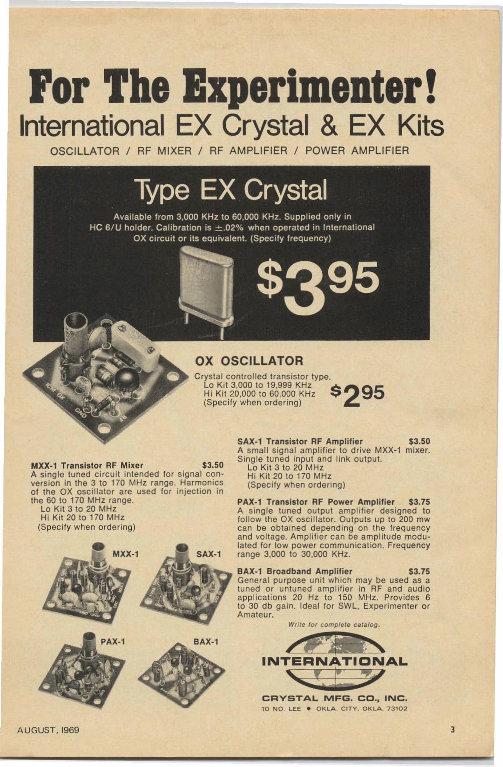
or experimenter!International EX Crystal & EX Kits
OSCILLATOR / RF MIXER / RF AM PLIFIER / POWER AM PLIFIER
OX OSCILLATOR
Write tor complete ca talog.
SAX·1 Transistor RF Amplifier $3.50A small signal am pl ifier to d rive MXX-1 mixer.Single tu ned input and li nk output.
La Kit 3 to 20 MHzHi Kit 20 to 170 MHz(Specify when ordering )
PAX·l Transistor RF Power Amplifier $3.75A single tuned output amplifie r designed tofo llow the ox oscil lator. Outputs up to 200 mwcan be obtained depending on the frequencyand vol tage. Ampl ifier can be amp l itude modulated for low power communicat ion. Frequencyrange 3,000 to 30,000 KHz.
BAX·l Broadband Amplifier $3.75General purpose unit wh ich may be used as atuned or untuned amplifier in RF and audioappl ic at ions 20 Hz to 150 MH z. Provides 6to 30 db ga in. Id eal for SWL, Experimenter orAmateur.
SAX-,
C rystal controlled transistor type.l o Kit 3,000 to 19,999 KHz $ 295Hi Kit 20,000 to 60,000 KHz(Specify wh en ord er ing)
MXX·'
MXX·l Transistor RF Mixer $3.50A single tuned c irc ui t intended for signal con vers ion in the 3 to 170 MHz range. Harmonicsof the OX oscillator are used for injection inthe 60 to 170 MHz range.
l o Ki t 3 to 20 MHzHi Kit 20 to 170 MHz
(Specify when order ing)
PAX-' SAX-,
CRYSTAL MFG. CO.• INC.10 NO. LEE • OKLA CITV. OKLA, 7310.2
AUGUST, 1969 J
Listen In
on Two-Meter
W. G. Eslick, KQ>VQY2607 E. 13thWichita , KA 67214
FM Repeater
For those who don't have a two meterrM receiver and want to listen to therepeater (if you have one in your area) thislittle converter will do a very good job intoan AM radio.
You will recognize this converter as beingsimilar to police converters. (In fact, changing the crystal and repeaking the antennacoil should put a police converter in the hamband).
The unit is built on a printed board 2-1/8by 2-5/8 inches. The capacitors are aU frommy junk box and include small roundtubular, round Oat ceramics and small milartypes.
QI and Q2 are 2N2996's, but 2NI141'sand TI XM I O's all work fine on three volts.Three volts was selected because my converter works into a radio that runs on twopenlight cells. If you plan to use 6 or 9 volts,RI, R2, R3 and R4 will have to be changedto other values (found by experiment andmeasuring base voltages and collector currents). My unit, using 2N2996's draws 8-1 /2rna at three vol ts.
After building, determine by gdo orreceiver if the crystal is oscillating at threetimes its frequency (I tune my 6 meter rig tothe fundamental frequency of the crystal orrather its overtone frequency), or if it isoscillating at crystal frequency , it will be okat 3 times. Then place the converter nearyour be receiver loop antenna and tune it tothe approximate frequency (your if in thiscase) or, using a signal generator or a signalfrom the repeater, adjust the converterloopstick for maximum signal or noise. Witha signal picked up from repeater, adjust CI
for maximum. I am near the repeater and Iuse about a 10 inch whip for my antenna.
You are receiving FM by slope detection,so tune your be radio for the clearestreception. Some will be clearer than others,depending how close to the frequency theyare. You won't receive them as crystal clearas an FM receiver, but this will let you listen10.
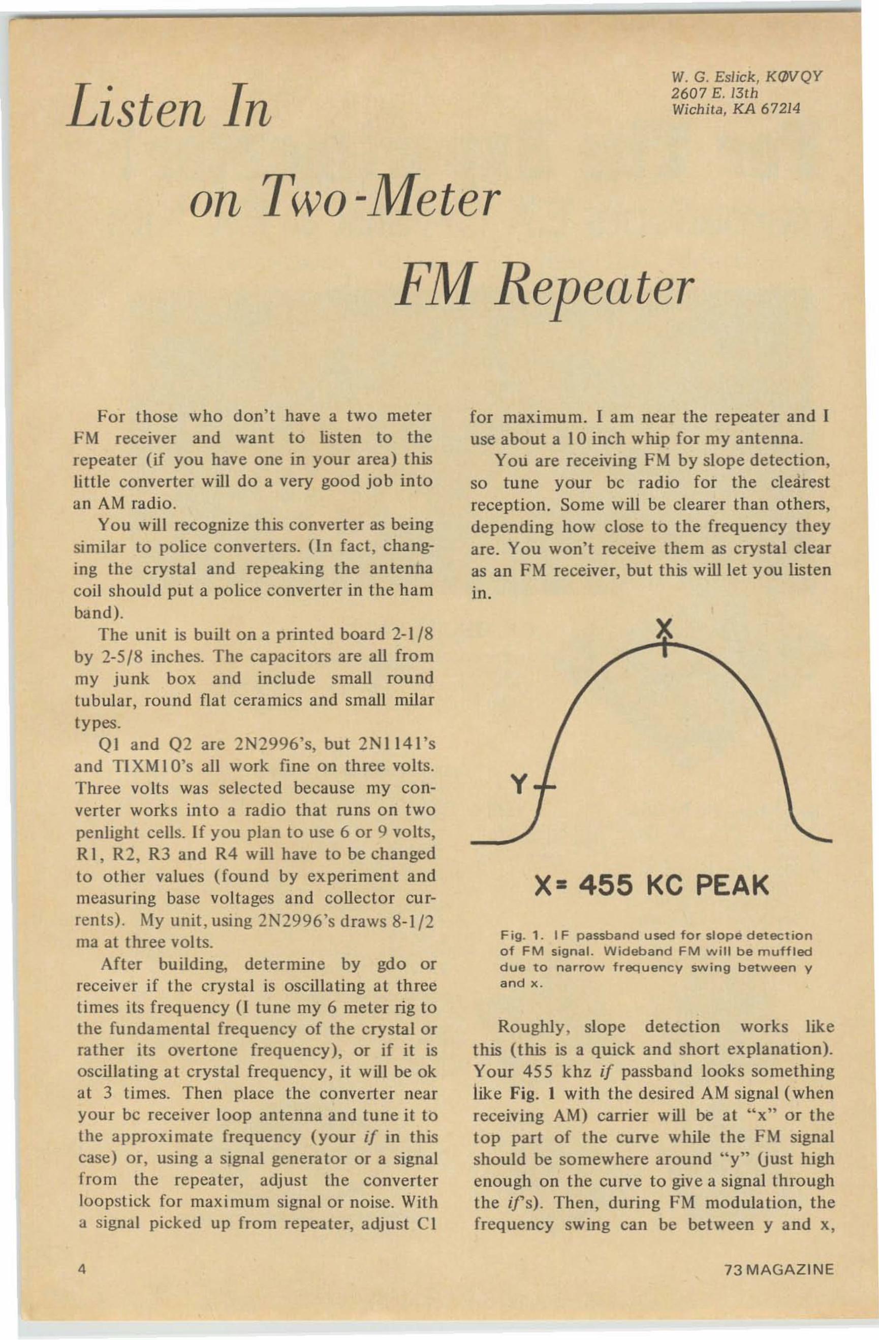
y
x= 455 KC PEAK
Fig. 1. I F passband used for slope detectionof FM signal. Wideband FM w ill be muffleddue to narrow frequency swing between yand x .
Roughly, slope detection works likethis (this is a quick and short explanation).Your 455 khz if passband looks somethinglike Fig. I with the desired AM signal (whenreceiving AM) carrier will be at "x" or thelop part of the curve while the FM signalshould be somewhere around "y" (just highenough on the curve to give a signal throughthe ifs) . Then, during FM modulation, thefrequency swing can be between y and x,
73 MAGAZINE
.. . KqJVQY
transistor if strip, the slugs vary the frequency very little, less than one mhz.
Getting back to you who plan to use a beradio. You will have to use this math to suityour crystals and also keep away from bestations (pick a clear spot on the be dial). Inmy rig I used a 48.71 6 crystal, giving me aninjection frequency of 146.148 mhz on thelow side of the repeater frequency.146.94-146.148=792 khz, where I pick upthe repeater.
The extreme ends of the be band, usingthe xtal on the low side and the high side,are:146.940 - 1.600 =145.340 ~ 3 = 48.4466 mhzlow side .146.940 + 1.600 = 148.540 -;- 3 = 49.5133 mhzhigh side.
146.940 - .550 = 146.390 -7 3 = 48.7966 mhzlow side.146.940 + .550 = 147.490 -7 3 = 49.1633 mhzhigh side .
There we have it. A crystal between 48.7966and 48.4466 will permit the repeater tocorne in between 550 khz and 1600 khzwith the oscillator working on the low sideof the incoming signal at the antenna, whilea crystal between 49.1633 and 49.5133 willpermit the repeater to corne on the be bandbetween 550 and 1600 khz with the oscillator working on high side of the signal at theantenna. So, in other words, if you have athird overtone crystal in your junk boxbetween 48.4466 and 49.5133 you can putthe repeater into the be band!
One note of warning of a trouble thatcost me a mixer transistor (2N2966).Jamming C3 under the loopstick (which iselevated about 1/4" from the board by abracket), one lead broke on C3 and when Ifired the converter up it was oscillating likemad on the be band. This made the transistor draw more current and finally destroyitself. So check all parts to make sure a leadhasn't broken. Inspect everything closelyand heatsink the transistor leads withtweezers or a long nose while soldering themto the board or, better yet, use transistorsockets.
Good luck and pleasant listening on 2meter FM.
'"
I B ·~ A I n "LG
",.U ~-25
2N2996
£z t ac
ca ~ ","0.~ cs t.z
T 00'
"." ,rSWITz z«
",
c r '" .., ",'" I .,
4 l ~."-.
ca
"' ; F: C5':":~,
,,~' 0,
".!5 T 11I0 22 1/4 "DIA CLOSE WOUND,c,~
5T NO l8 CI,
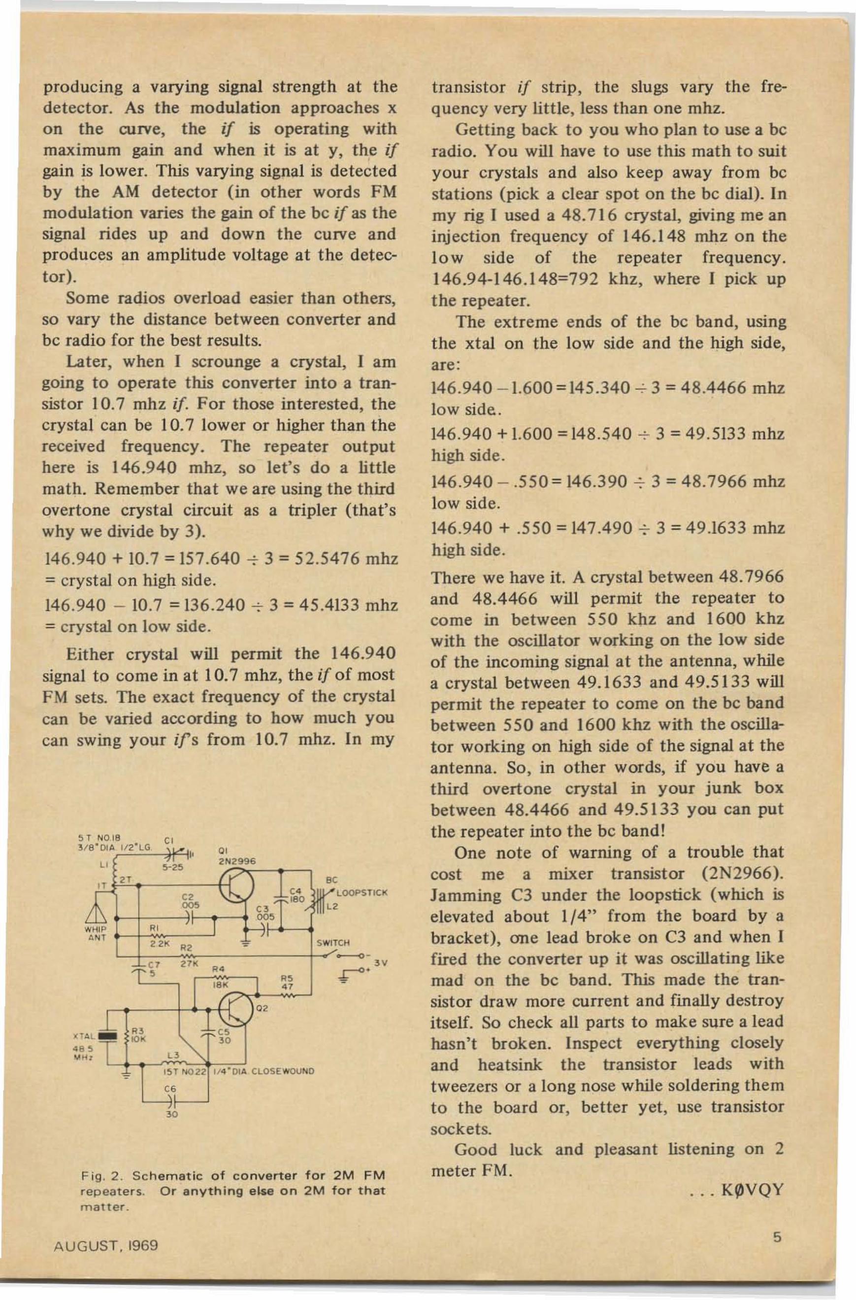
Fig. 2 . Sc hem at ic of converter for 2M FMrepeat er s. Or anything etse on 2M for thatmat ter .
producing a varying signal strength at thedetector. As the modulation approaches xon the curve, the if is operating withmaximum gain and when it is at y, the ifgain is lower. This varying signal is detectedby the AM detector (in other words FMmodulation varies the gain of the be if as thesignal rides up and down the curve andproduces an amplitude voltage at the detector).
Some radios overload easier than others,so vary the distance between converter andbe radio for the best results.
Later, when I scrounge a crystal, I amgoing to operate this converter into a transistor 10.7 mhz if. For those interested, thecrystal can be 10.7 lower or higher than thereceived frequency. The repeater outputhere is 146.940 mhz, so let's do a littlemath. Remember that we are using the thirdovertone crystal circuit as a tripler (that'swhy we divide by 3).
146.940 + 10.7 = 157.640 -; 3 = 52.5476 mhz= crystal on high side.
146.940 - 10.7 = 136.240 -r- 3 = 45.4133 mhz= crystal on low side.
Either crystal will permit the 146.940signal to corne in at 10.7 mhz, the if of mostFM sets. The exact frequency of the crystalcan be varied according to how much youcan swing your ifs from 10.7 mhz. In my
AUGUST . 19695
L. C. Maurer, W60SA209 Nob HilJ WayLos Gatos, CaUfornia 95030
An FET Regenenuice
or 3.5 mhz and Up
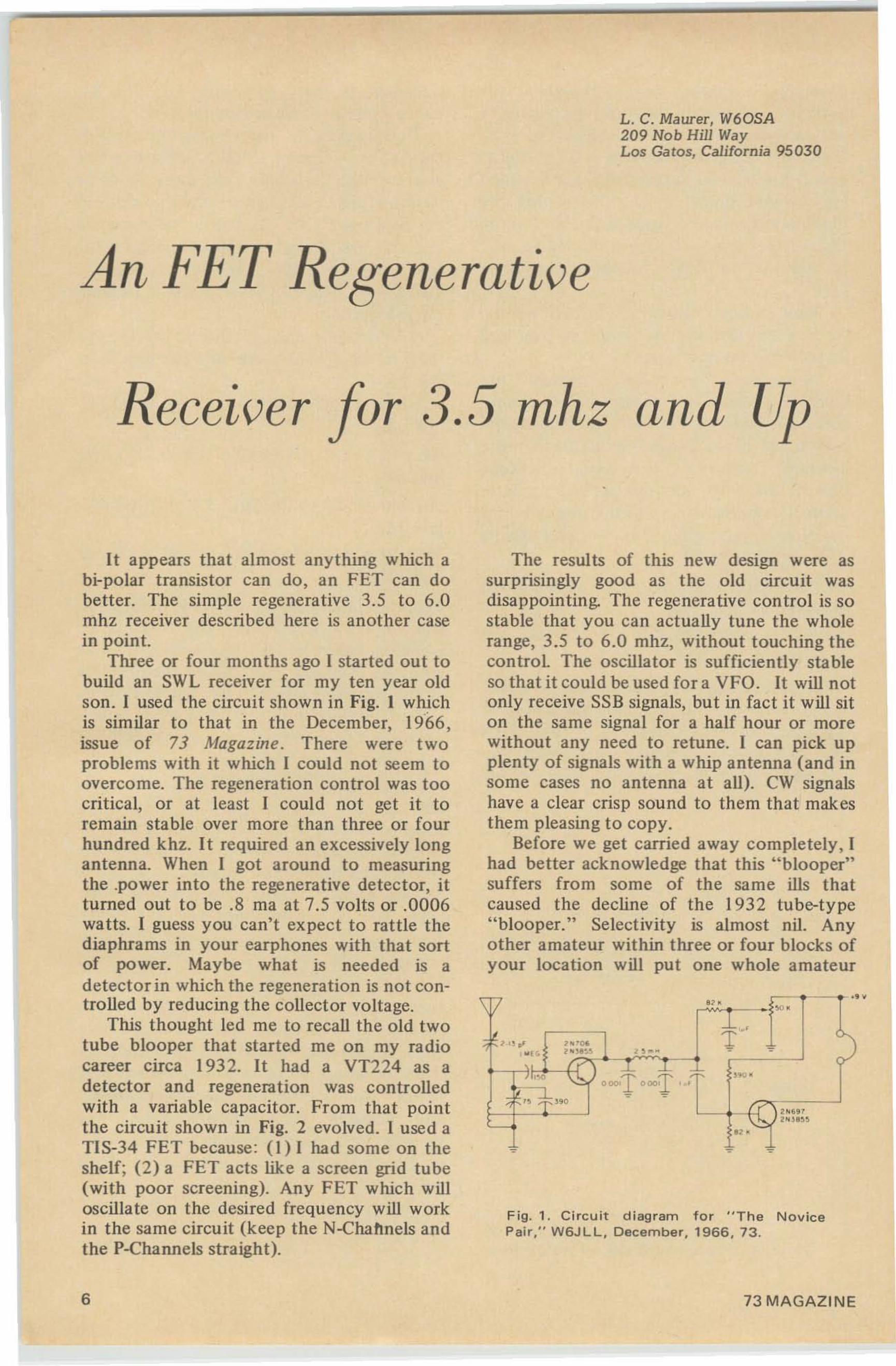
Fig. 1. Circuit diagram for "The NovicePair," W6JLL, December, 1966, 73.
."
..L
oooT000:.I'.,. -=-
1
The results of this new design were assurprisingly good as the old circuit wasdisappointing. The regenerative control is sostable that you can actually tune the wholerange, 3.5 to 6.0 mhz, without touching thecontrol. The oscillator is sufficiently stableso that it could be used for a VFO. It will notonly receive SSB signals, but in fact it will siton the same signal for a half hour or morewithout any need to retune. I can pick upplenty of signals with a whip antenna (and insome cases no antenna at all). CW signalshave a clear crisp sound to them that makesthem pleasing to copy.
Before we get carried away completely, Ihad better acknowledge that this "blooper"suffers from some of the same ills thatcaused the decline of the 1932 tube-type"blooper." Selectivity is almost nil. Anyother amateur within three or four blocks ofyour location will put one whole amateur
It appears that almost anything which abi-polar transistor can do, an FET can dobetter. The simple regenerative 3.5 to 6.0mhz receiver described here is another casein point.
Three or four months ago I started out tobuild an SWL receiver for my ten year oldson. I used the circuit shown in Fig. 1 whichis similar to that in the December, 1966,issue of 73 Magazine, There were twoproblems with it which I could not seem toovercome. The regeneration control was toocritical, or at least I could not get it toremain stable over more than three or fourhundred khz. It required an excessively longantenna. When I got around to measuringthe .power into the regenerative detector, itturned out to be .8 rna at 7.5 volts or .0006watts. I guess you can't expect to rattle thediaphrams in your earphones with that sortof power. Maybe what is needed is adetector in which the regeneration is not controlled by reducing the collector voltage.
This thought led me to recall the old twotube blooper that started me on my radiocareer circa 1932. It had a VT224 as adetector and regeneration was controlledwith a variable capacitor. From that pointthe circuit shown in Fig. 2 evolved. 1 used aTIS-34 FET because : (I) I had some on theshelf; (2) a FET acts like a screen grid tube(with poor screening). Any FET which willoscillate on the desired frequency will workin the same circuit (keep the N-Chahnels andthe P-Channels straight).
6 73 MAGAZINE
ea er
ea er
•
Sadly also. th is wasteful, heat producingcu rrent demand keeps right on evenwhen j ust l is tening. Thou ghts aboutthe cost of a new set of tubes at replace ment t ime can also be very disturbing indeed .
SB-34 owners who operate mobileareapt to be more relaxed. They need notbe undu ly co ncerned abo ut batt erydrai n so their t ran smi ssion s are a little
less hurried ---conversa tions more enjoya ble. Afterall, with 43 heaterless semiconductors and only 3 ofthose littl e glass bottles, every SB·34 is a heaterbeater! The odds of 43 to 3 can be even more in yourfavor when you use on ly the receiver to check out" who's where" . Flip your standby switch---heaters offand t he drai n from the car battery drops to a merehalf-amp trickle.
Battery drai n worries many mobile operators whouse al l-tu be transceivers---dam pens their enjoyment[ust thinking about those dozens or more vac uumtubes that are sitting there siphoning globs ofelectrons f rom t he car battery merely to keep theirgreedy litt le heaters glowing.
SB-34 is a passenger-please r also. Only 5" high, fitsunder dash an d leaves leg roo m. It weighs only 19pounds.v-handles like a briefcase. This is meaningfulat vacation time when you may wan t to shi ft it toyour plane or boat---or to a motel. Built -in powersupply is du al---1 2V DC and 1I 7V AC for j ust suchcont ingencies. Add, a " hot" receiver, Collins mechfilter, selectable SB's, solid-sta te switching (norelays), dua l-speed RX and TX tuning and mu ch,much more. 5 8·34 just has to be far out in front asthe top choice for mobile .
L/NEAR SYSTEMs./Ne220 Airport Boulevard, Watsonville, Calif . 95076
•
•
•
•
Write forfu ll detail s.
•
Taki ng that home stat ion tubeset on your vacation? Thentake the Century solid-statepower supply . 13V DC input ,output selectable t o meetHv/ current requirem ent ofany transceiver . Rugged, reoliable. polarity protected.short ci rcuit proof , overloadbreaker . Supply available forHnears too.
SI3E
" CENTURY", SOLID-STATEHV POWER SUPPLIES
,.
F ig . 3. A lte r nat e Ou tput c i rc u i t f or morega in .
-,..Ol · A~ [ 0 '..,:;[~ ..... z
.... 5'G ~ Al ! .O.. .. 5'G ~ " " ·, 0
! '_A
5' '.'
n.,,,,
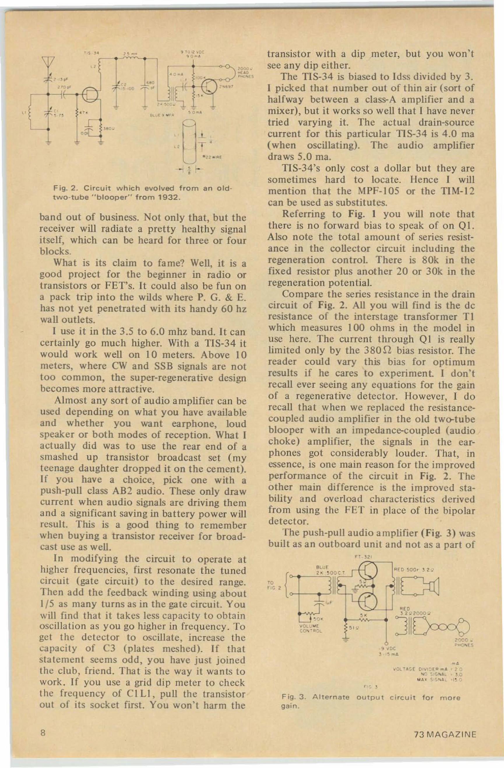
transis tor with a dip meter, but you won'tsee an y dip ei ther.
The TIS-34 is biased to Idss divided by 3.I picked that number out of thin air (sort ofhalfway be tween a class-A a mplifier and amixer), but it works so well that I have nevert ried vary ing it. The actual dra in-sourcecurrent for this particular Tl S-34 is 4.0 rna(when oscillating). The audio amplifierdraws 5.0 rna.
TIS-34's only cost a dollar but they aresometimes ha rd to locate. lienee I willmention that the MPF-105 or the TlM -12can be used as substitutes.
Referring to Fig. 1 you will note thatthere is no for ward bias to speak of on QI.Also no te the tota l amount of series resistance in the collector circuit including theregeneration control. There is 80k in thefixe d resistor plus anot her 20 or 30k in theregeneration potential.
Co mpare the series resistance in the draincircuit of Fig. 2. All you will find is the deresista nce of the interstage t ransformer TIwhich measures 100 ohms in the model inuse here. The current through QI is reallylimited only by the 380 n bias resisto r. Thereader could vary this bias fo r optimumresults if he cares to experiment. I don'trecall ever seeing any eq ua tions for the gainof a regenerat ive detector. However, I dorecall tha t when we replaced the resistancecoupled audio amplifier in the old two-tubeblooper with an impedance-coupled (audiochoke) a mplifier, the signals to the earphones got co nside rably louder. Tha t, to
essence, is onc main reason for the irn provedperformance of the circuit in Fig. 2. Theother main difference is the improved stabili ty and ove rload chara cteristics derivedfro m using the FliT in place of the bipolardetector.
The push-pull audio amplifier (Fig. 3) wasbuilt as an outboard un it and not as a part of
r.T '
Fig. 2 . Circuit which evolved from an o ldtwo-tube "blooper" from 1932 .
band out of business. No t only that, but thereceiver will radiate a pretty healthy signa litself, which can be heard fo r three or fo urblocks.
What is its claim to fame? Well, it is agood project for the beginner in radio ortransistors or FET's. It could also be fun ona pack trip into the wilds where P. G. & E.has not yet penetrated with its handy 60 hzwall outlets.
1 use it in the 3.5 to 6.0 rnhz band. It cancertainly go much higher. With a TlS-34 itwould work well on I 0 meters. Above 10meters, where CW and SSB signals are nottoo common, the super-regenerative designbecomes more att ract ive.
Almost any sort of audio a mplifie r can beused depending on what you have availableand whether you want earphone. loudspeaker or both modes of reception. What Iactually did was to use t he rear end of asmashed up t ransistor broadcast set ( myteenage daughter dropped it on the cement).If you have a choice, pick one with apush-pull class AB2 audio. These only drawcurrent when audio signa ls are driving themand a significant saving in battery power willresult. This is a good thing to rememberwhen buying a transistor receiver for broadcast usc as well.
In mo difying the circuit to opera te athigher freque ncies, first resonate the tunedcircuit (gate circuit) to the desired ran ge.Then add the feedback winding using about1/5 as many turns as in the gate circuit. Youwill find that it takes less capaci ty to obtainoscillat ion as you go higher in frequen cy. Toget the detector to oscillate, increase thecapacity of C3 (plates meshed). If thatstatement see ms odd, you have just joinedthe club, friend . That is the way it wants towork . If you use a grid dip meter to checkthe frequency of C I Ll, pu ll the transistorout of its socket first. You won 't harm the
••
B 73 MAGAZINE
,
•
"/r Speaks For Itself"
stgna// one
. --... -. ", ," IiI I ' ... ,....u If '!Il• ...-a1l 111il'il
. _-l ilt .<IUI -. 'til_. .. ta mil
, ::""':"_ .J
A Division of Eel (A n NCR Subsidiary )2200 An vil St. N , St. Pet er sb ur g, F la. 337 10
' T ha t's what I thought at the time. Later Iran across an almost identical circuit in aback issue of 73, (" A Two Meter Transceiver," II SLO, 73, July , 1965, Pg. 8.). Iwonder how I ISLO got Q18 to work wit hno dc return for its base?
. .. W60 SA
the basic receiver (Fig. 2). T he intention wasto use it as a utility amplifier around theshack as well as with the basic receiver whenloud speaker o peration was desired. Almo stall of the parts, including transformers, transis tors and speaker, were taken directly fro mthe smashed broadcast receiver. The o nenoteworthy addition is the volume co ntrol,and that is a W60SA original as far as Iknow.* It had to be put where it is insteadof in the usual place (i n fron t of the firs taudio stage) because otherwise it wouldinteract with the regeneration co ntro l. Notonly is it smooth and noiseless in o perationbut the co mbination of the linear potentio-
•meter and the I uf capaci tor produced anaudio taper effect.
The transistors in the Japanese portablehappened to be PNP's. The Japanese numberis FT-321 if that means anything to anybody. Actually you can use any PNP audiotransistor such as the 2N 188 A. You can alsouse NPN's. Just reverse the ba ttery andadjus t the voltage divider to provide asligh tly higher bias (if Si's).
As an added embellishment, I connectedmy favorite ~ I 5 rna meter in series with theaudio amplifier ba ttery lead. It works al mostlike an Svmete r, and my son can watch theneedle go up and down as he tunes instations. This proved to be a mistake. Nowhe won 't give the meter back.
After I had the basic receiver playingthrough the loud speaker, it occurred to methat it would be nice to have so me extra gainplu s a gain contro l available when listeningwith the headphones. So I klu ged up thealterna te ou tpu t circuit shown in (Fig. 3),The transformer is a red output transformer,single ende d type, from anot her defuncttransistor radio. I think I can guarantee thatonce you have tried it this way you won't goback to using the headphones with thebare foot receiver. This being the case youmigh t wish to incorporate the push-pullaudio in the basic receiver. I still prefer theo utboa rd arrangement because I envisionusing the amplifier for utility purposes,subjec t o f course to the whims o f numbertwo son.
A UG UST, I969 9
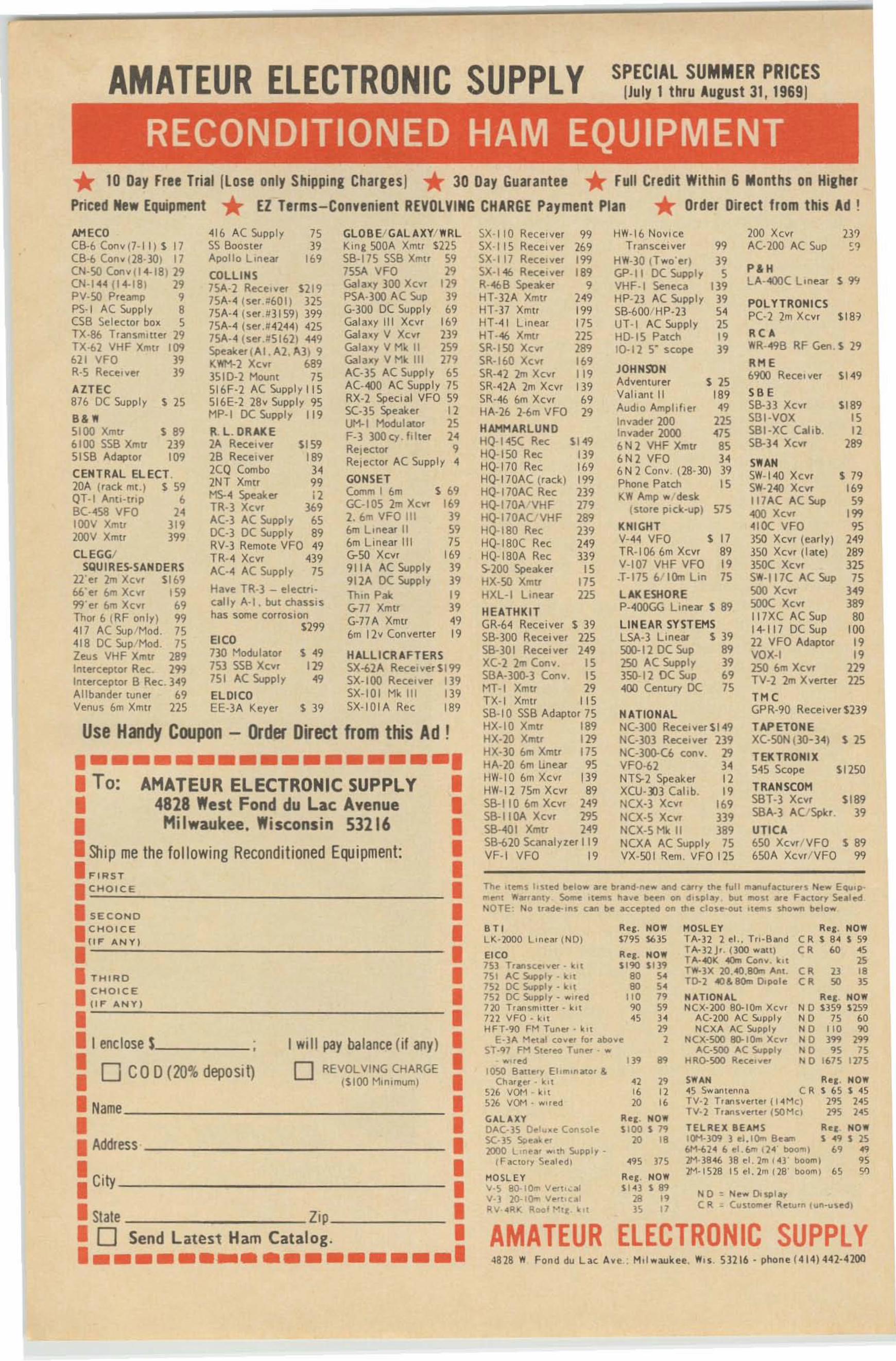
AMATEUR ELECTRONIC SUPPLY SPECIAL SUMMER PRICES[July 1 Ihru AUfusl 31, 19691
RECONDITIONED HAM EQUIPMENT* 10 Day Free Triai llose only Shipping Charges I * 30 Day Guarantee * full Credit Within 6 Months on Hia:her
Priced New Equipment * El Terms-Convenient REVOLVING CHARGE Payment Plan * Order Direct from this Ad !
AM ECO <416 A( Supply 75 GLOB E/ GAL AXYiWRLCB-6 (on ... (7· II) S 17 SS Booster 39 King SODA Xmtr $225ca-s ( onv( 28-301 17 Apollo Lmeae '" S8-17S SSB Xmu "CN·50Conv I14-18 ) 29 COLLINS 75SA VFQ 29CN-144 jl4-IBI " 75A-2 Rece.ver S219 Galaxy 300 Xcvr '"pV-SO Preamp ,
75A·4 Iser.=(01) m PSA- 300 AC Sup 19PS-I AC Supply ,
75A· 4 (s~ 113159) 399 G·300 DC SlJpply 69(58 Sel ector box s 7506,· " (ser.~ 4244) 425 Galaxy III Xc.... '"TX·86 TransmItter 29 75.·4 iser,IISl611 449 Galaxy V XcV' 239TX-{>l VHF Xmtr 109 Speaker( AI . A2 . .ro. JI 9 Galaxy V Mk II '"621 VFO J9 KWM-2 Xc:yr 68' Gala.y V Mk 111 179R-5 Receive- 39 3510·2 Moont 75 AC-35 AC Supply 65AZTEC 516F-2 AC Supply 115 AC·..oo AC Supply 75
876 DC Supply '" S16E-2 28 v Supply 95 RX-2 Special VFO 59
B& • MP_I DC SlJpply "'5(-35 Speake! 12Ut1-1 Modulato. 15
5100 Xmtr s e R. L. DRAKE F-3 3OOcy .ldte. H6100 SSB Xmtr 2J9 2A Recerver SI59 Relector ,5158 Adaptor 10' 28 Receiver 189 ReleClo. AC Supply "CENTRAL ELECT. 2CQ Combo l420A (rack me .) '59 2NT Xmer 99 GONSET
MS-.. Speaker 12 Comm I 6m s 69QT·I Anti·trlp ,
GC·105 2m Xcvr 1698C·"58 VFO H TR·3 XCY' 369IOOV Xmtr 319 AC-3 AC Supply 65 2. 6'l1 VFO 111 J9
200V Xmtr 399 DC·3 DC Supply 89 6m LInear II 59RV-3 Remote VFO "9 6m Linear 111 75
CLEGG/ TR· " Xcv- 439 G-5O Xcvr 169SQUIRES-SANO ERS AC·" AC Supply 75 91 1A AC Supply J9
22'e' 2m Xcvr SI69 912A DC Supply J9M'el 6m Xcyr 159 Have TR·3 - etecm- thin Pak 199'}'el 6m XCY' 69 c:ally A· l . but chaSSIS G-77 Xmtr J9Thor 6 (RF only) 99 has some corrosion G-77 A Xmtr 49"17 AC Sup/Mod. 75 S299 6m 12v Co- vener "" 18 DC Sup/Mod. 75 EICOZeus VHF Xmtr 289 730 Modu Iatcr '49 HALLICRAFTERSIntercepto, Rec: . '" 153 SS8 XCYI 129 SX-62A Recerver 51C)9In terceptor B Rec. 3"9 151 AC Supply 49 SX-IOO Receiver Il9Allbander tune. 69 ELOICO SX-IOI Mk III 13'Venus 6m Xmn 225 EE-3 A Ke-er ' J9 SX·IOIA gee '"
11.", . NO W' .9125" ...
""
R"I . NOWC II$S4 $59ell 1>0 45
"C R 2J 18CR 50 J5
R" I · NOWNO $359 U 59NO 75 60NO 110 90NO 399 299NO 95 75NO 1675 1275
TELAE. IlEAMS1(JH·309 1 ,,1 .IOm B"...6M--624 6 "t.6m O. boo"',lM-3S46 Ja.,I.2mI4J· bOO)/flI1M·15lll 15 ..l.2m(lB· boo"'~ 65
SWAN Re , . NOW4S S...ant"nna ell. $ 65 $ 45TV·} T' SV.,fl", (14MC) 2'1S 24STV·2 T, ve.u'lSOMcl 29S 245
HOSL EYTA·32 } ~I.. T,,·BandTt'H2J', noo ..."U)T 40K 4l)<n Cony. kllT -rx 1O.40.8Om An,.T002 40& 80m DoPOle
NATIONALNCX· 200 eO-10m Xcv,
AC·2oo AC SupplyNCX" AC Supply
NCX·SOl) llO-lOm X,y,"C-5OO "C Supply
HRo-5OO R",~,y",
NO : N"... o.",layC II. = Cy. l em" , lI~tu' n lun-u."ll l
139 89
42 2916 1220 16
11. " 1_ NO"lll$100 $ 7'1
'" "495 175
11. " 1 , NOW1141 $ 89
" "as 17
R~C . NOWS79S S63S
R" I . NOWS19Q $In
SO S4., "
110 1990 5945 H,.,,
""~dlOse Batt" 'y EI ,m on;oto< &Ch3'g~' . kol
526 YOM k>...516 YOM . ..""d
GAL Al Y0"C· 3S O..ly . ~ Con.ol ~
SC· 35 ~.,~ ...1000 L,n..a' ,,11 Supply .
(F~"tor1 5ealedl
MOSLEYy.!> BO· IO... Y"r ", ~ 1
V-l 2O-IOm V~' I , c~ 1
s.v .RK Roof r-' , ~ . "-,,
AMATEUR ELECTRONIC SUPPLY4828 "/11 Fond dy Lac Ay e,; M, I...aukee. I'/ ' S 51116 - phone (41"I"U-42Ql)
BTOLK· lOOO Lln~3 ' INO}EICO751 T.an~ ,,,' ..er - kl1
lSI AC Supply - I"t752 DC Supply· • •1752 DC SuWly ..."~d110 T.an.m.lt~r· k n122 VFO . k,rHFT·9Q FM Tun~'· . 01
E·3" M"tel COG"e' to' "'boY~5T.<0 FM St ~ , ,",, Tyner · ...
Th" ,r."",s Io~' "d be low at" b...d ·ne... and ,.ry Ihe lull manu/Klu.e. s "Ie... E"",p·m...,t 1'I"....ly Some ,,,.m~ lIay~ ~en on d,~play . bUI mos' .~ FKIOfy s.."le<INOTE : No trade'ln~ ,an ~ "c:c:"pl~ll on th~ c:lo~~'''''1 ","",s ~"o_ b~lc",
SX ·IIO Receiv er 99 HW·16 NOVice 200 XCY. '"SX ·115 Receiver '" Teaesceiver 99 AC 200 AC Sup "SX·117 Receiver 199 HW·30 ITwo'er) 19SX·I<\6 Rec:e,yer '" GP·' I DC Supply s P&.R·<\6B Speaker , VHF ·I Seneca Il9 LA·"!OO( Linea. '"HT·32 A Xmt. 249 HP-23 AC Supply 39 POL YTRONI CSHT·37 Xmtr '" S8-bOO/ HP·23 54 PC·2 2m xcvr S 1 8 ~HT-41 Linear "' UT· I AC Supply 15HT·4/) Xmtr 22' HD-IS Patch 19 R CASR·15O XCY' 289 10-11 S' sceee 19 WR·-49B RF Gen. S 29SR·lbO Xcyr 169
JOHNSUN RHESR··U 2m XCY! "' b900 Rect' Iver SI 49SR-42A 2m Xcvr 13'
Adventurer s as5R·-46 6m Xcvr 69 Valiant II '" SB E
HA·26 1-6m VFO 29 AudiO Ampld ' er 49 56-33 Xcvr SI89Inyade' 200 225 S131·VQX 15
HAMM ARLUN O InYader 2000 475 SBI-XC (allb. 12HQ- 14S( Rec 51 49 6N2 VHFXmtr 85 56-H xe..... 289HQ·15O Rec Il9 6N2 VFO 34HQ-I 70 Rec '" b N 2 Conv . (28·30) 19
S'flANHQ-170AC (rack) 19' Phone Patch 15
SW·1 40 XCY' ' 79HQ·170AC Rec 239 SW·240 XCY! '"HQ-170A 'VHF 279
KW Amp w/ desk Il7AC AC Sup 59(stole pidr.·up) 57' '100 XCYf 199HQ-170A(iVHF 289
HQ-180 Rec 239 KNIGHT 410( VFO 95
HQ·IBO( Rec 249 V· "4 VFO • 17 350 Xcvr (early) 249HQ· IBOA Rec 139 TR- I06 6m Xcvr 89 350 Xc", (Iale) 2895-200 Speaker 15 V·I07 VHF VFO 19 3SOC Xcyr J25HX·SI) Xmtr 17'
.T-17S b/11)n Un 75 SW·117C A( Sup 75HXL·I LInea. 22' LAK ESHORE SOO Xcyr '49HEATHKIT P-"OOGG Linear S S9 500C Xcvr '89
11 7XC AC Sup 80GR·64 Rece iver S 39 LINEAR SYSTEMS 1+ 117 DC Sup 10058-300 Receiver m LSA-3 Lmear '39 22 VFO Adaptor 1958·301 Receiver 249 500-12 DC Sup 89 VOX·l 19XC·2 2m Cony. 15 250 AC Supply 39 150 6m XCY! 229S13A-3ClO-3 Conv. 15 350-12 DC Sup 69 TV·2 2m Xvener 225MT-' Xmtr 29 400 Century DC 75TX·I Xmtr "' THe
SB·IO SSB Adapeor 7S NAT IONAL GPR·90 ReceiverS239
HX-IO Xmtr '" NC·3oo RecelyerSl "9 TAP ETONEHX·20 Xmtr 129 NC-303 Receiver 239 XC·SON (30· H l s zsHX-30 bm Xmtr 17' N(-300-Cb COIW. 29 TEKTRO NIXHA-20 bm uoea- 95 VFD·62 34 S45 Scope 51150HW-IO 6m Xcvr Il9 NT5-2 Speaker 12HW·12 75m XCY' 89 XCU- l:I3 Eabb. "
TRAN5COM
56-1 10 6m Xcvr 249 NCX·3 Xcve 169 S8T·3 xcvr 518956-1 lOA XCYI 29' NCX-S XCYI 139 SBA·3 ACtSpk•. 395B·401 Xmtr 249 N(X-S Mk II 389 UTICA5B-620 Sc:analyzer 119 NCXA A( Supply 75 650 Xcv. /VFO '89VF·t VFO 19 VX·SO I Rem. VFO 125 bSOA Xcvr/ VFO 99
REVOLVING CHARGErstoo Minimum)oo CO0 (10% deposit)
Use Handy Coupon - Order Direct from this Ad !
•••••••••••••••••••• To: AMATEUR ELECTRONIC SUPPLY •• 4828 IIesl Fond du Lac Avenue •• Milwaukee . IIisconsin 53216 •
• Ship me lhe following Recondi tioned Equipment: •• FI RST •• C HOICE •
• SECOND •
•CHOICE •"I'" "NY l• •
• THIRD •
•C HOICE •ti l'" " NY)• =...::::..:.:.-_ ------ - - .
• Ienclose I Iwill pay balance (if any ) •
• •• •• Na~ •
• •• Address •
: City :
• Slale lip .• 0 Send Latest Ham Catalog. ••••••••••••••••••••
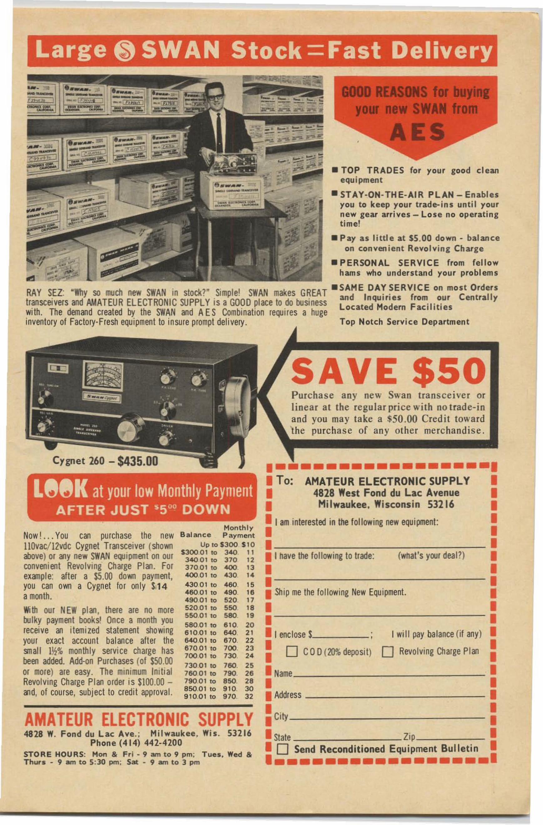
Large ~ SWAN Stock =Fast Delivery
Top Notch Service Department
• PERSONAL SERVICE from fellowhams who understand your problems
• TOP TRADES for your good cleanequipment
.STAY-ON-THE-AIR PLAN-Enable syou to keep your trade-ins unt il yournew gear arrives - Lose no operatingtime!
• Pay as little at $5.00 down - ba lan ceon conven ien t Revolv ing Charge
•••••••••••••••••••• To: AMATEUR ELECTRONIC SUPPLY •• 4828 West Fond du Lac Avenue •• Milwaukee. Wisconsin 53216 •
• I am interested in the following new equipment: •
• •• •• I nave !he following to Irade: (wnat's yoo. deal ' ) •
• •• •• Ship me the following New Equipment. •
• •• •• I enclose 1 I will pay ba lance (If any) •
: 0 CO D(10% deposit) 0 Revolving Charge Plan :
• Name •• •• Address •
• • •• City •
• State Zip •• 0 Send Reconditioned Equipment Bulletin ••••••••••••••••••••
Month lyB alance P ayment
Up 10 $300 $ 10$300 01 to ~ 11
34001 10 310 12310 01 10 400 1340001 to 430 1"430 01 to "50, 15" 60 01 to "90 16" 90 0 1 to 520 11520 0 1 to 550. 1855001 10 580 1958001 to 610. 206 10 01 to 640 2 1640 01 to 610 . 22610 0 1 to 700 2370001 to 730 2"73001 to 760, 25760 01 to 790 2679001 to 850. 28850.0 1 to 9 10. 3091 0 .01 to 970. 3 2
.., .'RAY SEZ: -Why so much new SWAN in stock?" Simple! SWAN makes GREAT _SAME DAY SERVICE on most Orderstransceivers and AMAT EUR ELECTRONIC SUPPLY is a GOOD place to do business and Inquiri es (rom our Centrally
Located Hodern Faciliti eswith. The demand created by the SWAN and AE S Combination requires a hugeinventory of Factory-Fresh equipment to insure prompt delivery.
AMATEUR ELECTRONIC SUPPLY4828 W. Fond du Lac Ave .; Milwaukee, Wis . 53216
Phone (414) 442-4200STORE HOURS: Mon & Fr i - 9 am to 9 pm; T ue s , Wed &Thur. - 9 am to 5 :30 pm ; Sat - 9 am to 3 pm
Cygnet 260 - $435.00
U~~K at your low Monthly PaymentAFTER JUST 'SODDOWN
Now! . .. You can pu rchase the newllOvac/ 12vdc Cygnet Transceiver (shownabove) or Mly new SWAN e(Jliprnent on OUIconvenient Revolving Charge Plan. Forexanple: after a $5 .00 down payment ,you can own a Cygnet fo r only $,14amonth.With our NEW plM, there are no moreootky payment books! Once a month youreceive an itemized statemen t showingyour exact account balance alter thesnail l~% monthly service charge hasbeen added. Add·on Purchases (01 150.00or more) are easy. The minimum InitialRevolving Charge Plan order is SlOO.OO an d, of course, subject to credit approval.
Lawrence Mowry, Jr. WA7EVX661 Virginia - Box 352Coos Bay, Oregon
Multi- Channel FM Operation
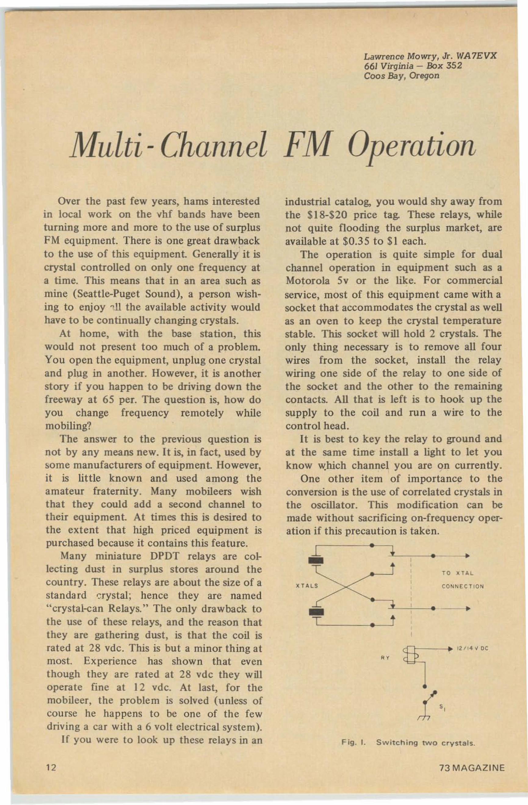
Fig . I. Switch ing two crystals.
TO kTA L
CONNECTIO N
o ·
o
o
_ -....-l_~_o __•T - t
1:----1_ -,----<0 --.
x TAl S
;B~--+ 12/1 4 '1 OC
industrial catalog, you would shy away fromthe $18-$20 price tag. These relays, whilenot quite flooding the surplus market, areavailable at $0.35 to $1 each.
The operation is quite simple for dualchannel operation in equipment such as aMotorola 5v or the like. For commercialservice, most of this equipment came with asocket that accommodates the crystal as wellas an oven to keep the crystal temperaturestable. This socket will hold 2 crystals. Theonly thing necessary is to remove all fourwires from the socket, install the relaywiring one side of the relay to one side ofthe socket and the other to the remainingcontacts. All that is left is to hook up thesupply to the coil and run a wire to thecontrol head.
It is best to key the relay to ground andat the same time install a light to let youknow which channel you are on currently.
One other item of importance to theconversion is the use of correlated crystals inthe oscillator. This modification can bemade without sacrificing on-frequency operation if this precaution is taken .
Over the past few years, hams interestedin local work on the vhf bands have beenturning more and more to the use of surplusFM equipment. There is one great drawbackto the use of this equipment. Generally it iscrystal controlled on only one frequency ata time. This means that in an area such asmine (Seattle-Puget Sound), a person wishing to enjoy ell the available activity wouldhave to be continually changing crystals.
At home, with the base station, thiswould not present too much of a problem.You open the equipment, unplug one crystaland plug in another. However, it is anotherstory if you happen to be driving down thefreeway at 65 per. The question is, how doyou change frequency remotely whilemobiling?
The answer to the previous question isnot by any means new. It is, in fact, used bysome manufacturers of equipment. However,it is little known and used among theamateur fraternity. Many rnobileers wishthat they could add a second channel totheir equipment. At times this is desired tothe extent that high priced equipment ispurchased because it contains this feature.
Many miniature DPDT relays are collecting dust in surplus stores around thecountry. These relays are about the size of astandard crystal; hence they are named"crystal-can Relays." The only drawback tothe use of these relays, and the reason thatthey are gathering dust, is that the coil israted at 28 vdc. This is but a minor thing atmost. Experience has shown that eventhough they are rated at 28 vdc they willoperate fine at 12 vdc. At last, for themobileer, the problem is solved (unless ofcourse he happens to be one of the fewdriving a car with a 6 volt electrical sys tem).
If you were to look up these relays in an
12 73 MAGAZINE
THE BUT VALUE WI:HAVE EVER Ol' FUI E.
•
GOOD TH ROUGH 2 METE R
OUR MODEL S W B - ~
ADDU P OS TAGE
fA ST SERVIC E
OUR OWNPROFESSIONAL
SA N JOS E, CALIf' . 95128
S.W. R. BRIDGE andFIELD STRENGTH METER
9 9 5
MAY BE LEFTIN LINE UP
H
S. W. R. BR I OGEMOD El.S W8_1~E"DS FOR . ... IlD AND
IlEFLEeTED PO _EllS' ''VL r ",,, e OUSLT
"eAn IlEAo" .. ETEllSUSE FOR REFE RENC E
PO wEll METEIlDU "'L l!Xl _MICRO..MP
Me TE R MO~E "E N TS
LO W '''' SER TlO", LOSS
ADD SI FOR POSTAGE
PHONE ARE A 408 _294 _ 04U
Our Own High QualityInter-com System
•MODEL~C-Z
$9.9SFOR 2 UNITS. ADO11 FOR SHI PPING
4 TRA NSISTORS 250 MWAUDIO PW R
CALi fOR NI A RE!>IO ENTS INCLUOE S PE RCEN T SA L ES TAX
QUEMENT
At2=,-':;:1l0 0 UCT
~I N C E 1933
1000 ~O U T N 8A~COM AVE .
n. boo " • • 1." ~.
ho• • • • • ' .ff.,.I'
OUR MOST COPIED PRODUCT" T HO US AN DS SOLO "
MAY BE LEFT INLI NE, UP
TO 2.000 WATTS
SHIPP ED PllE P. ID US.OUE"EHT ..ODEL ..T . 2
Co..pl . , . ..... ;,o"o~,,~.c o,,~
C'OT~'O C • • • .,NCc ... , TUT "'C'.'N_
OT."C"O~ "'N"".~o UTUO, ..
T~ -.I. of I,n , I~ , .~_ ' _ , -.1;0"", . ,,, .1.1_ .
P,ofen ;onally App,o•• c1 D. I",.. 20,000 Oltm Voh YOMCOM P L ET E WITH L EAT HER CAS E
XI.OOO OHMS VOLT 0(_10.000 01; ,,5 VOLT"'Co..i, ~ ,..,1It ....<100" DC VQIl'i< ; s·tS·1OO·:5000·1000f " . -co' ''' ..ponded scal. AC Vo ll' II" ' 5-25·100·500· ]000Prot i" on 1'\0 ''''"l llu DC Cu".n!: Si),J '·S·50·5QO MAl .... ,,,,Y'1 load'". 11..,,,..,«, 6K·60K-600K-l;MEG-60r0e._J~I'" ...1.. _._,1 0..:,"'10: ·20 10 <'lOll
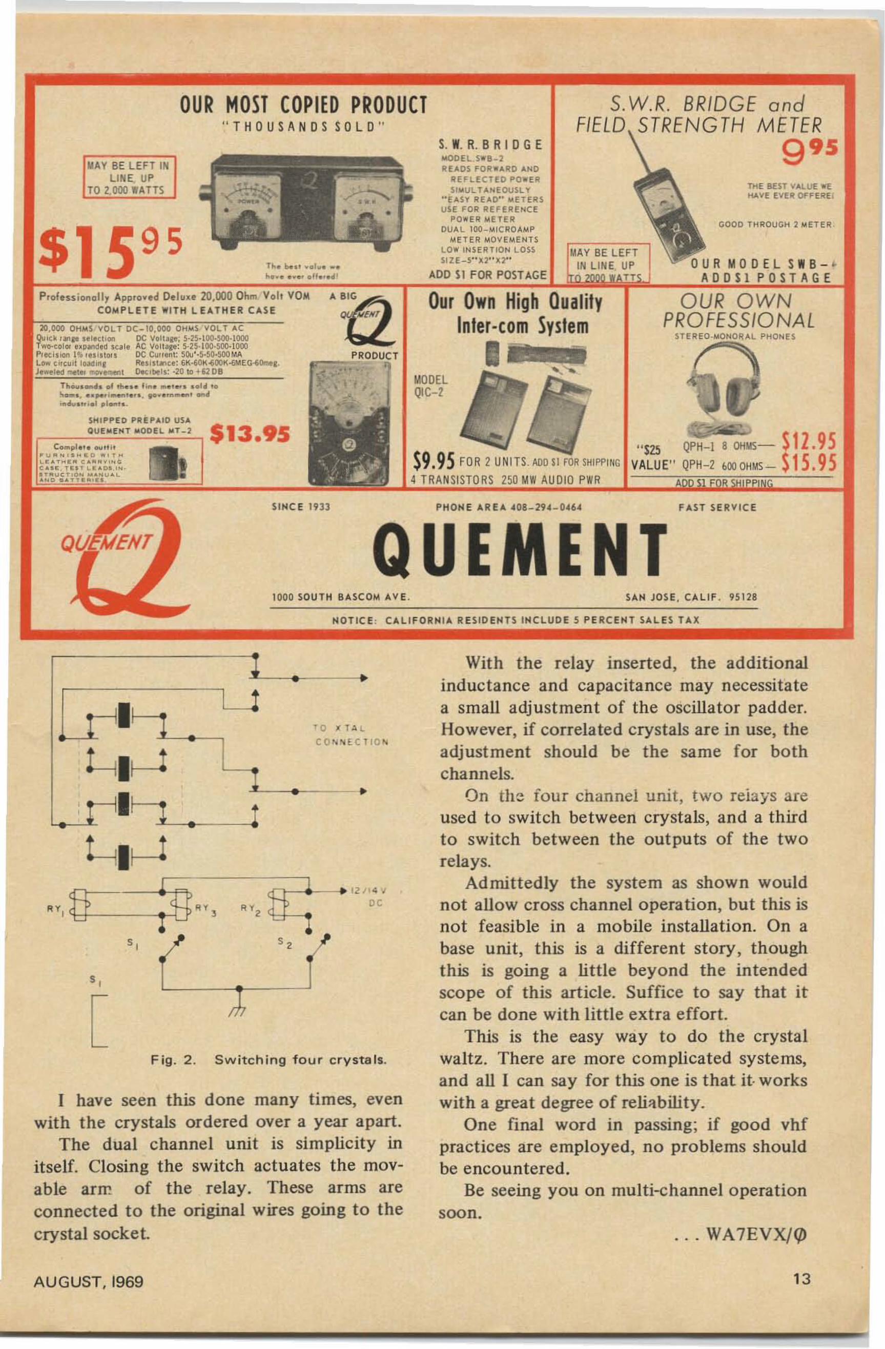
Fig . 2 . Switching four crystals.
1.-_.-__•
I have seen this done many times, evenwith the crystals ordered over a year apart.
The dual channel unit is simplicity initself. Closing the switch actuates the movable arm of the relay. These arms areconnected to the original wires going to thecrystal socket. . .. WA 7EVX/CIJ
With the relay inserted, the additionalinductance and capacitance may necessitatea small adjustment of the oscillator padder.However, if correlated crystals are in use, theadjustment should be the same for bothchannels.
On the iour channel unit, two relays areused to switch between crystals, and a thirdto switch between the outputs of the tworelays.
Ad mittedly the system as shown wouldnot allow cross channel operation, but this isnot feasible in a mobile installation. On abase unit, this is a different story, thoughthis is going a little beyond the intendedscope of this art icle. Suffice to say that itcan be done with little extra effort.
This is the easy way to do the crystalwaltz. There are more complicated systems,and all I can say for this one is that it- workswith a great degree of reliability.
One final word in passing; if good vhfpractices are employed, no problems shouldbe encountered.
Be seeing you on multi-channel operationsoon.
' 0 • TALCO.... tCT IO..
•
Lrll~--+----,e-..!
~II.-1,11
[
l_~ •
-"!---..-~!
L lr--J
~r--------'I
<A ~ fH, ",~-. 1 1 /~C'" ' 'tl - ~
"
AUGUST. 1969 13
John J . Schulte , W2EEY I J40 Rossie Stree tMystic . Connecticut 06 355
The Case or the 5/8 A Ver t ical
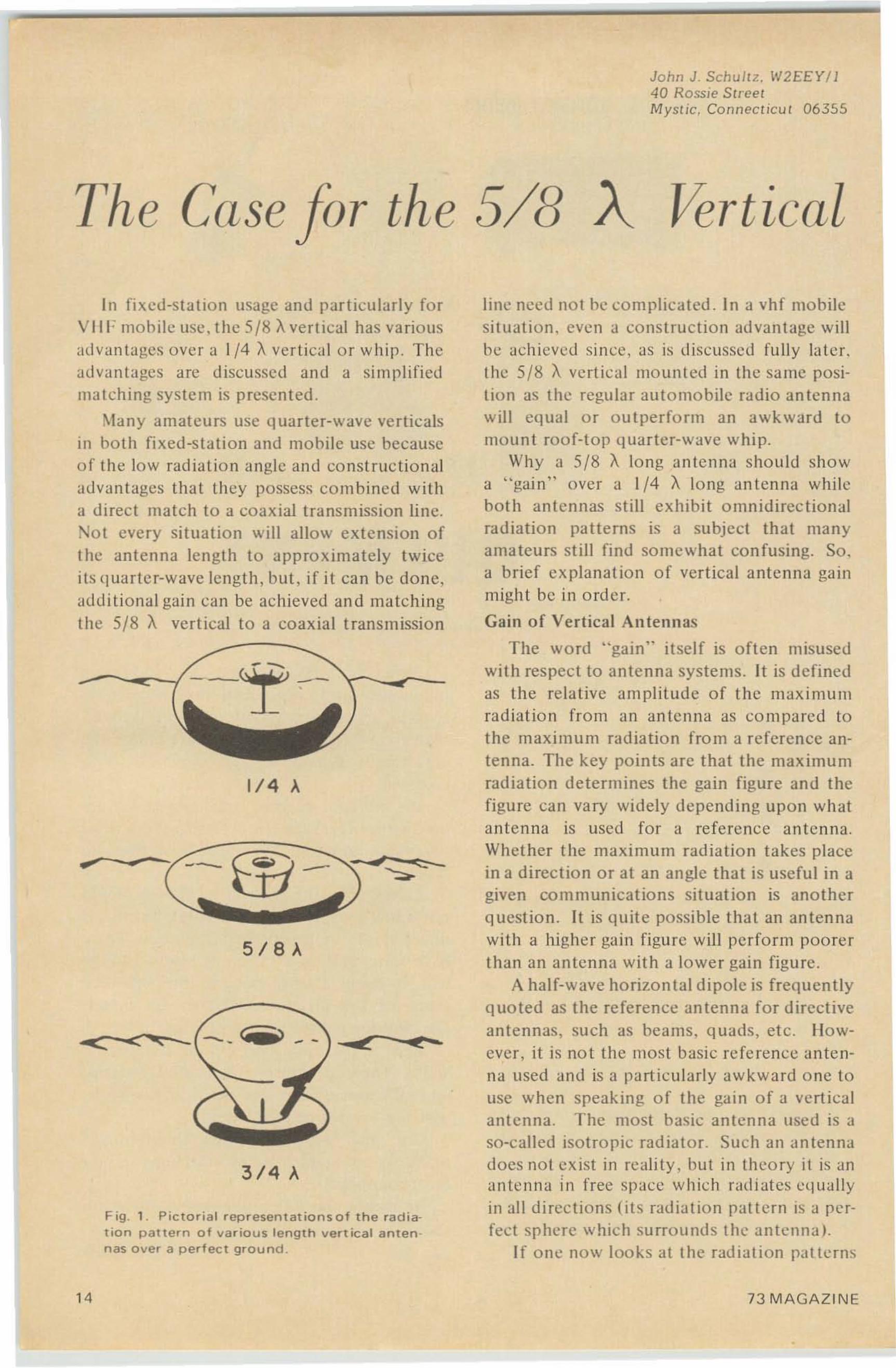
Fig . 1 . Pic to ria l r ep r esent at ions of the rad iation pattern of v ar io us length vert ica l anten nas over a perfect ground .
line need no t be com plica ted . In a vhf mobiles ituat ion. even a co ns t ruc tion advantage willhe achi eved since, as is discussed fully later.th e 5/8 A. vertical mounted in the sa me positi on as t he regular automobile rad io antennawill equa l o r o u t perfo rm an awkward tomoun t roof-top quarter-wave w hip.
Why a 5{8 A lo ng anten na sho uld sho wa "gain " over a 1/4 A. long an tcnna whileboth an tennas st ill ex hib it o mnid irec tio nalradiation patterns is a subject that manyama teu rs st ill fi nd so me wha t co n fusing. So .a brief explanation o f vertical an tenna gainmight be in order.
Gain of Ve rtica l Antennas
The wo rd "gain" it self is o ften misuse dwi th respect to antenna systems. It is definedas the relative amplitude of the maxim umra dia tio n from an antenna as compared tothe maximum radiation from a reference antenna. The key po ints arc that the maximumrad iation determines the gain figure and thefigure can vary widely depending upon whata nten na is used for a re ference a nten na.Whet her the maximum rad iation tak es placein a direction o r at an a ngle that is useful in agiven com munica t ions sit uat io n is ano t herquestion . It is quit e po ssible that an antennawith a higher gain figure will perform po ore rthan an a nte nna wit h a lo wer gain figure .
A half-wave horizontal dipole is frequentlyquoted as the reference an tenna for directiveantennas. su ch as bea ms , quads, et c . Ho wever , it is no t the most basic re fe ren ce antenna used and is a part ic u larly awkward o ne tousc when speaking o f the gai n o f a verti calan te nna. T he most basic a n ten na used is aso-called isotro pic rad ia to r. Such a n a ntennado cs not ex ist in real it y . but in t heo ry it is anante nna ill free space w hich radi at es eq uallyin all d irection s (its radia tion patt ern is a perfect sp he re which surro u nds t he un tcnna I.
If o ne no w loo ks at the radiation pa t te rn s
~--
1/4 A.
5/8A.
--•4
3/4 A.
C <..""'< - - - <iiii>
In fixed-sta t io n usage and particul arly forV II F mobile usc . the 5 /8 Aver tical has va riousadvantages over a 1/4 A. ver tical o r whi p. Theadvantages a rc d iscussed and a sim plifiedma tching sys te m is presented .
Many a mateurs usc quart er-wave verticalsin bot h fix ed-station and mobile usc becauseof t he lo w radiatio n angle and const ruct ionaladvantages that they possess co m bined witha d irec t match to a coaxial transmission line.No t every sit uat io n will allow e xtension ofthe antenna length to appro ximately twiceit s quarte r-wave length, but, if it can be done,addi tional gai n can be achieved an d match ingthe 5/8 A. vert ical to a co axial t ransmission
14 73 MAGAZIN E
5 10 IS W 25 ~ 35 40 45 ~ 55 60
,
•c
'000
III ~
'"'"sc
000
'0'
."•• '"•c,-0 '"••-•• '"-•
ace
'"c
1100
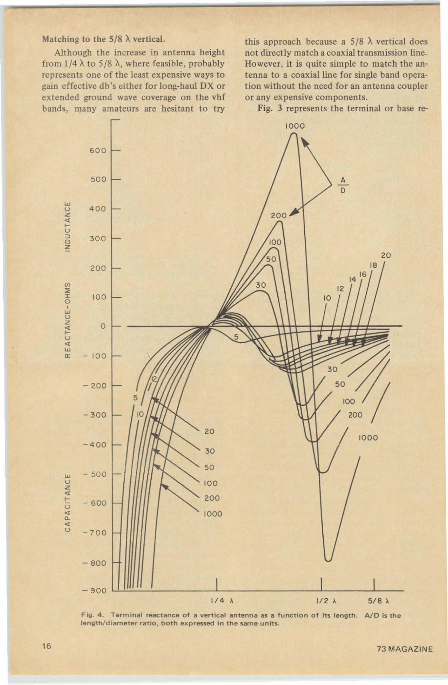
Fig. 3. Vertical antenna terminal resistanceas a function of length. A/D is the ratio ofantenna length to antenna diameter (d) .
- ,--
1/ 4 A VERTlC,c,L
..--- 5 /9 ,\ VERTICA L
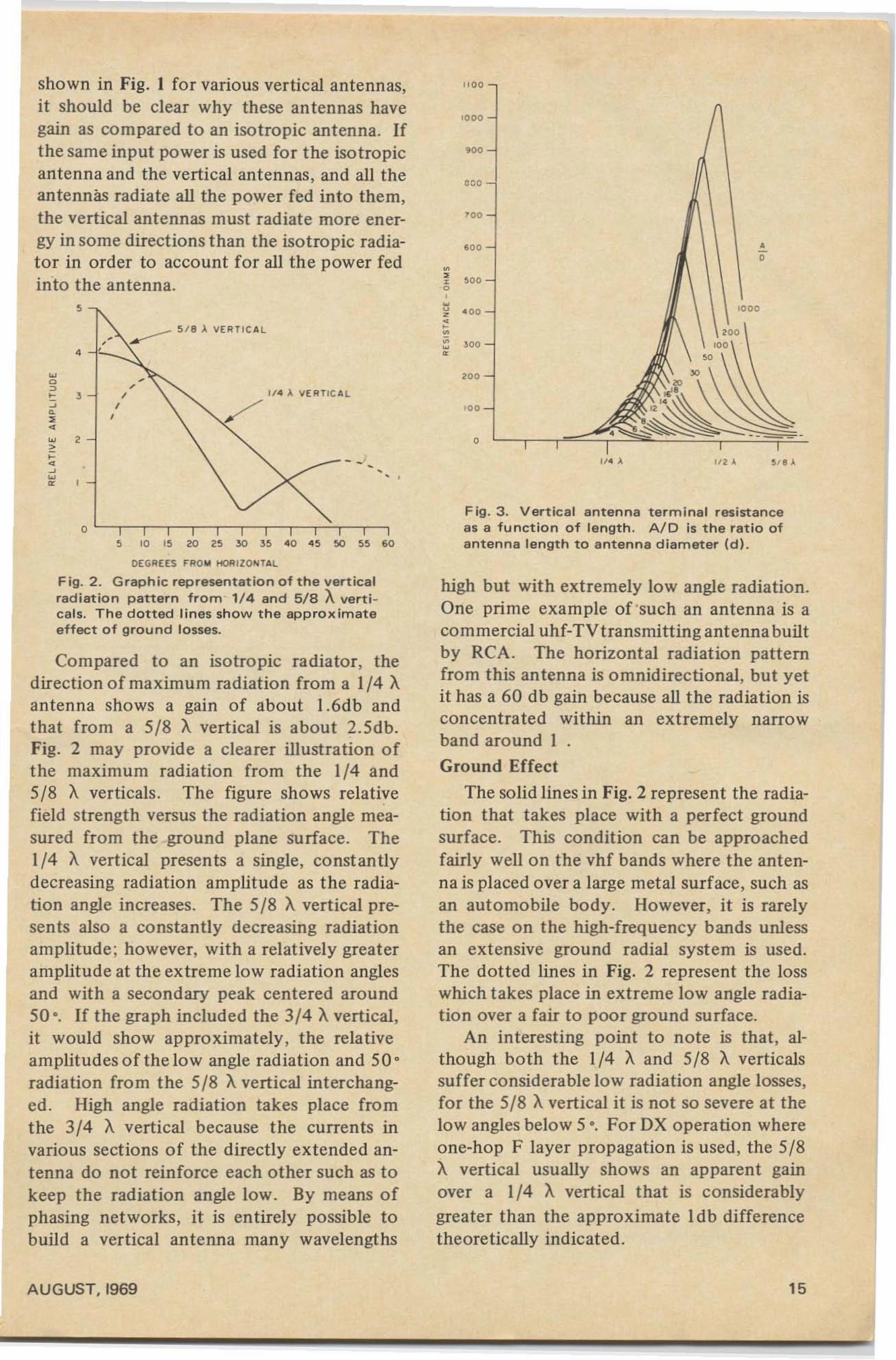
,-c, ,• , ," t• r>•- 2>••"-•
shown in Fig. 1 for various vertical antennas,it should be clear why these antennas havegain as compared to an isotropic antenna. Ifthe same input power is used for the isotropicantenna and the vertical antennas , and all theantennas radiate all the power fed into them,the vertical antennas must radiate more energy in some directions than the isotropic radiator in order to account for all the power fedin-to the antenna.
DEGREES FROM HOIUlO,,",TAL
Fig. 2 . Graphic representation of the verticalradiation pattern from · 1/4 and 5/8 Averticals. The dotted lines show the approximateeffect of ground losses.
Compared to an isotropic radiator, thedirection of maximum radiation from a 1/4 Aantenna shows a gain of about 1.6db andthat from a 5/8 A vertical is about 2.5db.Fig. 2 may provide a clearer illustration ofthe maximum radiation from the 1/4 and5/8 A verticals . The figure shows relativefield strength versus the radiation angle measured from the ground plane surface. The1/4 A vertical presents a single, constantlydecreasing radiation amplitude as the radiation angle increases. The 5/8 A vertical presents also a constantly decreasing radiationamplitude; however, with a relatively greateramplitude at the extreme low radiation anglesand with a secondary peak centered around50 ' . If the graph included the 3/4 Avertical,it would show approximately, the relativeamplitudes of the low angle radiation and 50'radiation from the 5/8 A vertical interchanged . High angle radiation takes place fromthe 3/4 A vertical because the currents invarious sections of the directly extended antenna do not reinforce each other such as tokeep the radiation angle low. By means ofphasing networks, it is entirely possible tobuild a vertical antenna many wavelengths
high but with extremely low angle radiation.One prime example of'such an antenna is acommercial uhf-TVtransmitting antenna builtby RCA. The horizontal radiation patternfrom this antenna is omnidirectional, but yetit has a 60 db gain because all the radiation isconcentrated within an extremely narrowband around IGround Effect
The solid lines in Fig. 2 represent the radiation that takes place with a perfect groundsurface. This condition can be approachedfairly well on the vhf bands where the antenna is placed over a large metal surface, such asan automobile body. However, it is rarelythe case on the high-frequency bands unlessan extensive ground radial system is used.The dotted lines in Fig. 2 represent the losswhich takes place in extreme low angle radiation over a fair to poor ground surface.
An interesting point to note is that, although both the 1/4 A and 5/8 A verticalssuffer considerable low radiation angle losses,for the 5/8 Avertical it is not so severe at thelow angles below 5 '. For DX operation whereone-hop F layer propagation is used, the 5/8A vertical usually shows an apparent gainover a 1/4 A vertical that is considerablygreater than the approximate Idb differencetheoretically indicated .
AUGUST, 1969 15
Matching to the 5/8 Avertical.
Although the increase in antenna heigh tfrom 1/4 Ato 5/8 A, where feasible, probablyrepresents one of the least expensive ways togain effective db's either for long-haul DX orextended ground wave coverage on the vhfbands, many amateurs are hesitant to try
this approach because a 5/8 A vertical doesnot directly match a coaxial transmission line .Ho wever, it is quite simple to match the antenna to a coaxial line for single band operation without the need for an antenna coupleror any expensive components.
Fig. 3 represents the terminal or base re-
10 0 0
5 0 0 A-0
"'u 4 0 0z 200«I-u::> 300C>z
20
200 18
14 16U>
12:>I 10 0 100, I"'uz
0«I-u«"'0: - 10 0
600
- 8 0 0
- 9 0 01/4 A 1/2 A 5/8 ~
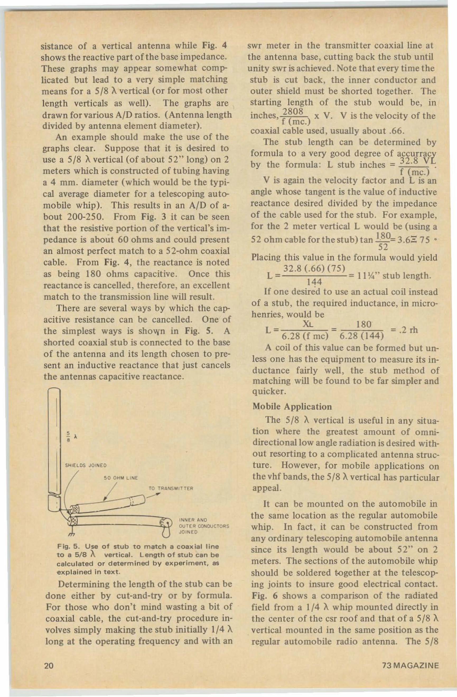
F ig. 4 . Terminal reactance of a vert ical antenna as a function of its length.length/ diameter ratio , both expressed in the same units.
AID is the
16 73 MA GA ZI NE
THIS CAN BE YOUR "BIG BREAK"if you're a man who's ever said ...
OH,JIMIS IN
ELECTROHICSNOW
AW, HONEY,I 'M BUSHED.
THAT LOUSYJOBOF MINE •••
o
DON'T FORGET, DEAR,WE'VE GOT A DATE
FOR TH E MOVIESWITH JIM ANDHELEN TONIGHT
OH SAY, JIM AN D HELEN HAVE,ALL RIGHT A NICE PLACE HERE.
WONDER WHERE HE GETSTHE MONEY?
PLEASE, DEAR. BESIDES,WE DON 'T GET OUT
THAT OFTEN •• •
YOU SEEMMIGHTY HAPPY
IN ELECTRONICS,J IM. LEVEL
WITH ME-HOW'DYOU BREAK IN?
EASIER THAN YOU MIGHTTHINK. WITH elE
TRAINING, I LEARNEDEVERYTHING I NEEDED
RIGHT AT HOM E.••IN M Y SPARE TIME!
-"1
BUT DON'T- I NEEDCOLLEGE •••7
ClIIIll!A =
City_ _ State Zip
o Veterans & Servicemen : check here for G.I . Bill informationAccredited Member National Home Study Council ST.2 1
L J
HOW ABOUT YOU" WANT AGREAT JOB IN ELECTRONICS,
TOO?GETFULlFACTS IN CIE's2FIIEE 6001<5. SEND BOUND-IN
CARD NOW!
Address
/
(p1eas.e pnot )
AU GUST, I969 19
50 0 t' 1oI LI NE
SHIELDS JOINED
swr meter in the transmitter coaxial line atthe antenna base, cutting back the stub untilunity swr is achieved. Note that every time thestub is cut back, the inner conductor andouter shield must be shorted together. Thestarting length of the stub would be, in
inches, i~~~.) x V. V is the velocity of the
coaxial cable used, usually about .66.The stub length can be determined by
formula to a very good degree of accurracyby the formula : L stub inches = 32.8 VL
f (mc.)V is again the velocity factor and L is an
angle whose tangent is the value of inductivereactance desired divided by the impedanceof the cable used for the stub . For example,for the 2 meter vertical L would be (using a
52 ohm cable for the stub) t an 180= 3.6::: 7 5 •52
Placing this value in the formula would yield32 .8 (.66) (75)
L = 144 = II \1." st ub length.
If one desired to use an actual coil insteadof a stub, the required inductance, in microhenries, would be
XL 180L = 6.28 (f me) - 6.28 (144) = .2 rh
A coil of this value can be formed but unless one has the equipment to measure its inductance fairly well , the stub method ofmatching will be found to be far simpler andquicker.
Mobile Application
The 5/8 A vertical is useful in any situation where the greatest amount o f omnidirectional low angle radiation is desired without resorting to a complicated antenna structure. However, for mobile applications onthe vhf bands, the 518 Avertical has particularappeal.
It can be mounted on the automobile inthe same location as the regular automobilewhip. In fact , it can be constructed fromany ordinary telescoping automobile antennasince its length would be about 52" on 2meters. The sections of the automobile whipshould be soldered t-ogether at the telescoping joints to insure good electrical contact.Fig. 6 shows a comparison of the radiatedfield from a 1/4 A whip mounted directly inthe center of the csr roof and that of a 518 Avertical mounted in the same position as theregular automobile rad io antenna. The 518
INNER ANDOUTER CONDUCTORSJOI NED
TO TRANS IoIITTER....--
~ ,•
Fig. 5 . Use of stub to match a coax ial lineto a 5/8 A vertical. Lengt h of stub can becalc ulated o r determined by experiment, asexp lai ned in t e xt .
Determining the length of the stub can bedone either by cut-and-try or by formula .For those who don't mind wasting a bit ofcoaxial cable , the cut-and-try procedure involves simply making the stub init ially 1/4 Along at the operating frequency and with an
sistance of a vertical antenna while Fig. 4shows the reactive part of the base impedance.These graphs may appear somewhat complicated but lead to a very simple matchingmeans fo r a 5/8 Avertical (or for most otherlength verticals as well). The graphs aredrawn fo r various AID ratios. (Antenna lengthdivided by antenna element diameter).
An example should make the use of thegraphs clear. Suppose that it is desi red touse a 5/8 Averticai (of about 52" long) on 2meters which is constructed of tubing havinga 4 mm. diameter (which would be the typical average diameter for a telescoping automobile whip). This results in an AID of about 200-250. From Fig. 3 it can be seenthat the resistive portion of the vertical's impedance is about 60 ohms and could presentan almost perfect match to a 52-o hm coaxialcable. From Fig. 4 , the reactance is notedas being 180 ohms capacitive. Once thisreactance is cancelled , therefore, an excellentmatch to the transmission line will result .
There are several ways by which the capacitive resistance can be cancelled. One ofthe simplest ways is shown in Fig. 5. Ashorted coaxial stub is connected to the baseof the antenna and its length chosen to present an inductive reactance that just cancelsthe antennas capacitive reactance.
20 73 MAGAZINE
COWL MOUNTE D~/8)o. VERTI CAL
CENTE R ROOF1/<1 )0. VERT ICAL
-t- II-+- ftH-f-
RELATI VE Fl E LOSTRE NGTH
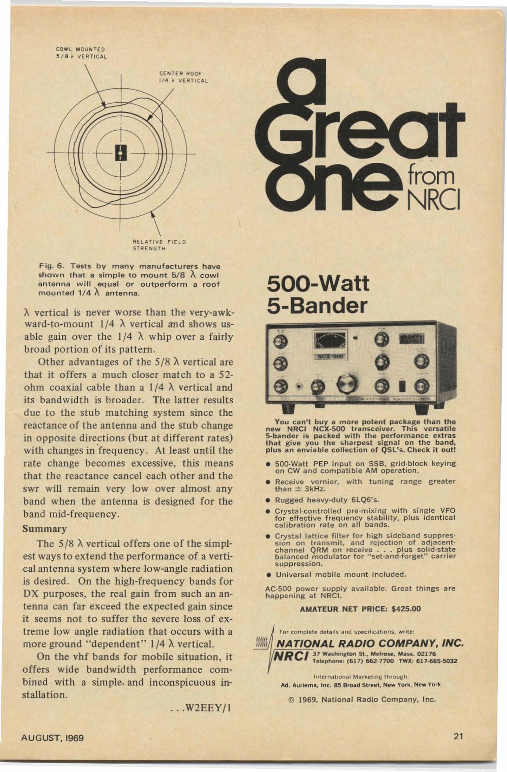
Fig. 6 . Test s by m any m a n u fact u rers h aveshown that a sim p le to mount 5 / 8 A cowlan ten na w i ll equal or outperform a roofm ounted 1/4 A an t en na.
A vertical is never worse than the very-awkward-to-mount 1{4 A vertical and shows usable gain over the 1{4 A whip over a fairlybroad portion o f its pattern .
Other advantages of the 5{8 A vertical arethat it offers a much closer match to a 52ohm coaxial cable than a 1{4 A vertical andit s bandwidth is broader. The latter resultsdue to the stub matching system since thereactance of the antenna and the stub changein opposite dire~tions (but at different rates)with changes in frequency . At least until therate change becomes excessive, this meansthat the reactance cancel each o ther and t heswr will remain very low over almost anyband when the ante nna is designed for theband mid-frequ ency.
Summary
The 5{8 Avertical offers o ne of t he simplest ways to extend the performance of a vertical antenna system where low-angle radiationis desired. On the high-frequency bands forDX pu rposes, the real gain fro m such an antenna can far exceed the expected gain sinceit seems not to suffer the severe loss of extreme low angle radiation that occurs with amore ground " dependent " 1{4 Avertical.
On the vhf bands for mobile situation, itoffers wide bandwidth performance combined with a sim ple. and inconspicuous inst allalion.
. . .W2EEY{I
AUGUST. 1969
fromNRCI
SOO-Watt5-Bander
~ !!- E)
~ C 0-- .
(j • e • 0.. A'-' ..",", "'",.
You ca n ' t bu y a more potent package than thenew NRCI NCX·500 transceiver. Thi s versatiles-beneer is packed wi t h the performance ex t rasthat g ive you th e shar pest signal on the band,plus an enviab le collection of QSL's. Check it out!
• 500·Watt PEP inp ut on SS B, g r id- b lock keyingon CW a nd compati b le A M opera t ion.
• Recei ve vern ier . with tuning range g reate rthan ± 3kHz.
• Rugg ed heavy-d uty SLQS's.
• Crystal-controlled pre -mix ing wi t h single VFOfor effect ive freq uency st abi l ity, p lus identic alca l ibration rat e o n all bands .
• Crysta l lattice filter for high sideband suppression on transmit, and rejecti on o f adjacentchannel QRM on receive .. . plus solid-statebalanced modulator for "set-and-forget" carrie rsup press ion.
• Uni versal m obil e m ount included.
AC·500 power supply availabl e. Great things arehappen ing at NRCI.
AMATEUR NET PRICE: $425,00
For complete eetaus and spec ,f icahOnS, wrot!! :
UW/, NATIONAL RADIO COMPANY, INC.NRCI 31 WU h ,ngton St.• Melrose, Mu s . 02176
Telep hone: (611) 662·7100 TWX: 61 1·665 ·5032
I" lel nat,ona l Mdrkel,ng t hrough :
Ad . Auriema. Inc . 85 Broad Street, New York, New York
© 1969, Nati on al Rad io Com pany, Inc.
21
The Genesis oBill Hood, WlUSM229 Quincy Shore DriveQuincy, Maryland 02171
Radio
Recently, in one of the larger electronicsstores, my eye was caught by the advertisingblurb on the box containing a crystalreceiver kit, "using the same circuits used byMarconi. . .. .. It struck me as being a ratherbold sucker attraction, since the crystaldetector didn't really get going for at least acouple of decades after Marconi's historymaking transmission.
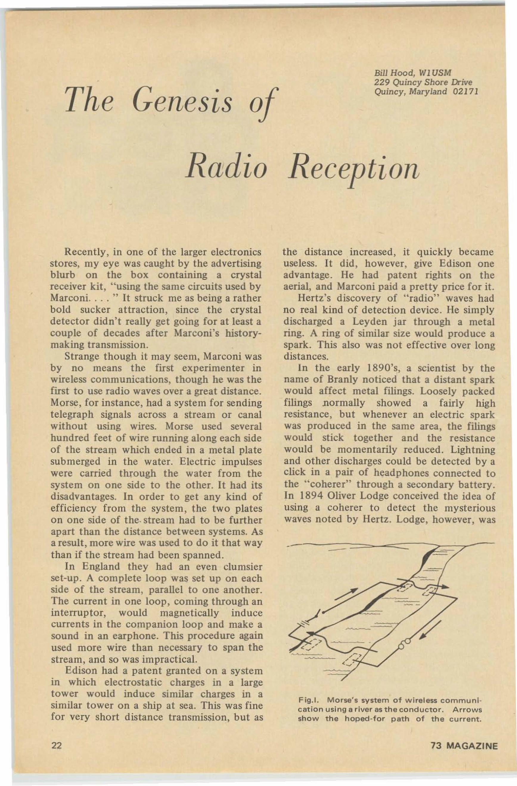
Strange though it may seem, Marconi wasby no means the first experimenter inwireless communications, though he was thefirst to use radio waves over a great distance.Morse, for instance, had a system for sendingtelegraph signals across a stream or canalwithout using wires. Morse used severalhundred feet of wire running along each sideof the stream which ended in a metal platesubmerged in the water. Electric impulseswere carried through the water from thesystem on one side to the other. It had itsdisadvantages. In order to get any kind ofefficiency from the system, the two plateson one side of the. stream had to be furtherapart than the distance between systems. Asa result, more wire was used to do it that waythan if the stream had been spanned .
In England they had an even clumsierset-up. A complete loop was set up on eachside of the stream, parallel to one another.The current in one loop, coming through aninterruptor, would magnetically inducecurrents in the companion loop and make asound in an earphone. This procedure againused more wire than necessary to span thestream, and so was impractical.
Edison had a patent granted on a systemin which electrostatic charges in a largetower would induce similar charges in asimilar tower on a ship at sea. This was finefor very short distance transmission, but as
22
Reception
the distance increased, it quickly becameuseless. It did , however, give Edison oneadvantage . He had patent rights on theaerial, and Marconi paid a pretty price for it.
Hertz's discovery of "radio" waves hadno real kind of detection device. He simplydischarged a Leyden jar through a metalring. A ring of similar size would produce aspark. This also was not effective over longdistances.
In the early 1890's, a scientist by thename of Branly noticed that a distant sparkwould affect metal filings . Loosely packedfilings normally showed a fairly highresistance , but whenever an electric sparkwas produced in the same area, the filingswould stick together and the resistancewould be momentarily reduced . Lightningand other discharges could be detected by aclick in a pair of headphones connected tothe "coherer" through a secondary battery .In 1894 Oliver Lodge conceived the idea ofusing a coherer to detect the mysteriouswaves noted by Hertz. Lodge, however, was
Fig.1. Morse's system of wireless communIcation using a river as the conductor. Arrowsshow the hoped ·for path of the current.
73 MAGAZINE
not working in communication. He wasexperimenting in the field of electromagnetism, so he never patented his idea.About that time, Marconi entered thepicture.
By applying Lodge's idea, and adding anantenna and ground circuit, Marconi wasable to transmit for several miles. Marconi'sfirst receiver used a coherer for a detector,coupled to a tuning system invented byLodge. His first attempts were so successfulthat he had little trouble getting the backingnecessary to form the British MarconiWireless Telegraph Co. Before long, however,he abandoned the coherer for a system of hisown invention (with considerable help fromLodge and Fleming, two top physicists ofthat day). This consisted basically of atransformer, the primary winding of whichwas in the antenna-ground circuit. Thesecondary was connected directly to theearphone. Perhaps the most interesting partof this was the core of the transformer,which was an endless iron belt. This belt waskept moving through the transformer. A pairof large permament magnets kept the corecontinually magnetized in one direction.This might possibly have caused some sort ofa rectifying action, since currents in adirection favoring the magnetic flux of the
._- - - - - --::>:",...--
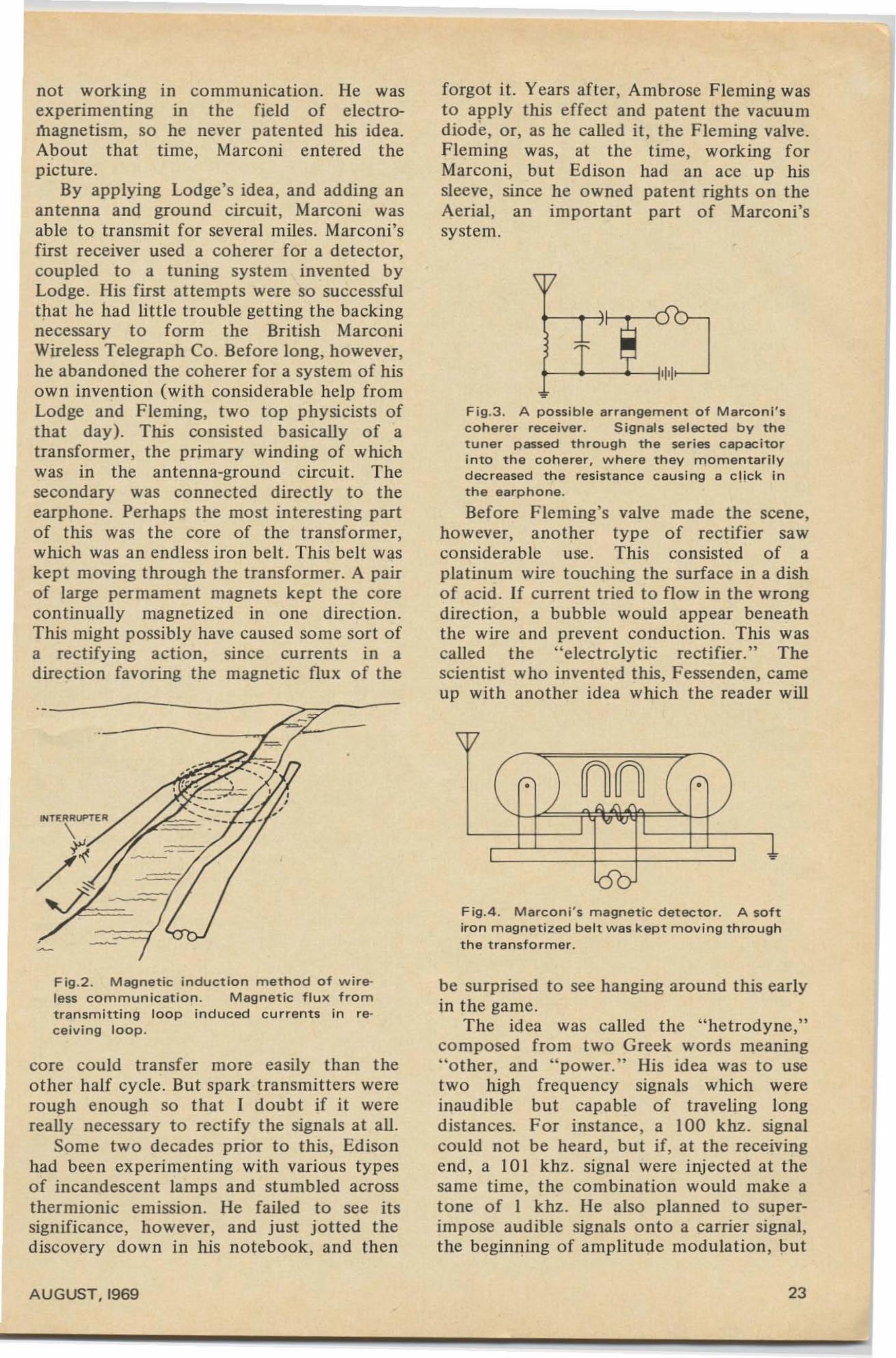
Fig.2 . Magnetic induction method of wtreless communication. Magnetic flux fromtransmitting loop induced currents in receiving loop.
core could transfer more easily than theother half cycle. But spark transmitters wererough enough so that I doubt if it werereally necessary to rectify the signals at all .
Some two decades prior to this, Edisonhad been experimenting with various typesof incandescent lamps and stumbled acrossthermionic emission. He failed to see itssignificance, however, and just jotted thediscovery down in his notebook, and then
AUGUST, 1969
forgot it. Years after, Ambrose Fleming wasto apply this effect and patent the vacuumdiode, or, as he called it, the Fleming valve.Fleming was, at the time, working forMarconi, but Edison had an ace up hissleeve, since he owned patent rights on theAerial, an important part of Marconi'ssystem.
Fig.3. A possible arrangement of Marconi 'scoherer receiver. Signals selected by thetuner passed through the series capacitorinto the coherer, where they momentarilydecreased the resistance causing a click inthe eerohone.
Before Fleming's valve made the scene,however, another type of rectifier sawconsiderable use. This consisted of aplatinum wire touching the surface in a dishof acid. If current tried to flow in the wrongdirection, a bubble would appear beneaththe wire and prevent conduction. This wascalled the "electrolytic rectifier." Thescientist who invented this, Fessenden, cameup with another idea which the reader will
Fig.4 . Marconi 's magnetic detector. A softiron magnetized belt was kept moving throughthe transformer .
be surprised to see hanging around this earlyin the game.
The idea was called the "hetrodyne,"composed from two Greek words meaning"other, and "power." His idea was to usetwo high frequency signals which wereinaudible but capable of traveling longdistances. For instance, a 100 khz. signalcould not be heard, but if, at the receivingend, a I0 I khz. signal were injected at thesame time, the combination would make atone of I khz. He also planned to superimpose audible signals onto a carrier signal,the beginning of amplitude modulation, but
23
the transm itters of that day were not goodeno ugh to make his idea practical.
Marcon i's co mpany owned aU rights onFleming's valve and flatly refused to licenseit to any American companies. It wassuperior enough to render his competitionineffectual. In order to keep from goingunder, a competitive device had to bediscovered. The answer came in the form ofgalena, carborundum, and other crystalswhich displayed rectifying qualities. Theso lid-state field was doomed to lie dormantfor a long time , how ever, thanks to a mannamed DeForest. DeForest had beenexperimenting with Fleming's valve, tryingto make it more efficient. lie first wrappedthe outside in foil , hoping to ionize theresidual gasses inside and therefore cause itto conduct more efficiently. It didn't worktoo well at first , so DeForest put the fo ilinside the valve. The results were encouraging. He then made the foil into aperforated plate between the filament andanode. Finally he tried a fine wire grid. Hehad done it ! The triode was born, and so waselectronics.
The first triodes were so large they werecalled " bo ttles," and glo wed so brightly theylit up the whole shack. At first they werekept highly secret. DeForest had his fir stmodel sealed up in a box with the lead ssti ck ing out. When he got it working, he lethis assistant listen. "My God, doc, hear thosesignals!" he cried, "What in H . . . have yougot in that box?" DeForest called his newdevice the Audion. He was able with littlet rouble , to sell his invention to the U. S.Navy, until some wise-guy technicians tried
- -~
'I >-
, ' I'I~
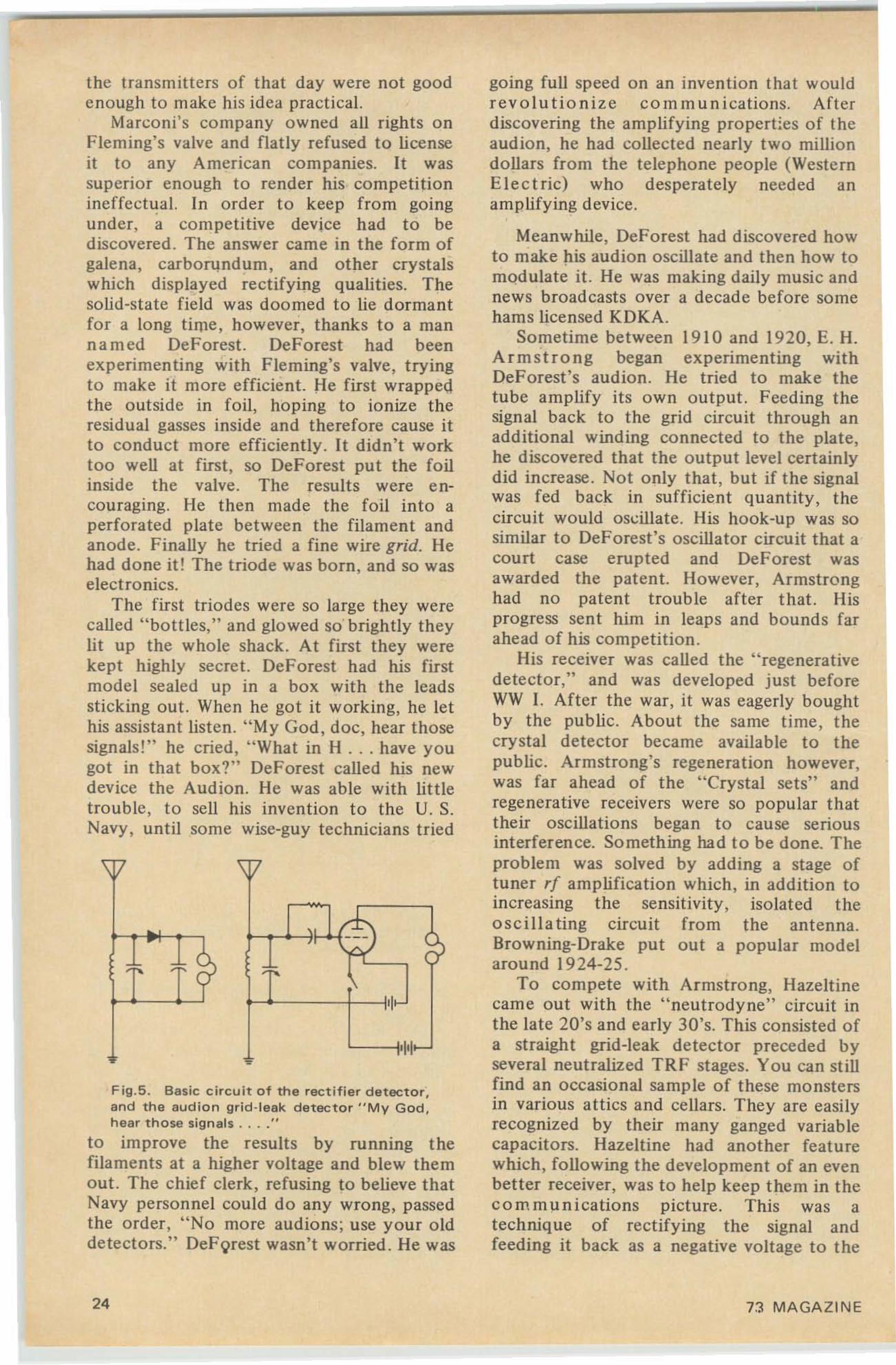
Fig.5. Basic circuit of the rectifier detector ,and the audion grid-leak detector " M y God ,hear th ose signals . . .."
to improve the results by running thefilame nts at a higher voltage and blew themout. The chief clerk, refusing to believe thatNavy personnel could do any wrong , passedthe order, "No more audions ; use your olddetectors. " Def'orest wasn't worried. He was
24
going full speed on an invention that wouldrevolutionize communications. Aft erdiscovering the amplifying pro pert ies of theaudion , he had collected nearly two milliondollars from the telephone people (Weste rnElec t ric) who desperately needed anamplifying device.
Meanwhile, DeForest had discovered howto make his audion oscillate and then how tomodulate it. He was making daily music andnews broadcasts over a decade before somehams licensed KDKA.
Sometime between 191 0 and 1920, E. H.Arm strong began experimenting withDeForest's audion . He tried to make thetube amplify its own output. Feeding thesignal back to the grid circuit through anadditional winding connected to the plate,he discovered that the output level certainlydid in crease. Not only that , but if t he signalwas fed back in sufficient quantity, thecircuit would oscillate, His hook-up was sosimilar to Def-orest's oscillator circuit that acourt case erupted and DeForest wasawarded the patent. However, Armstron ghad no patent trouble after that. Hisprogress sent him in leaps and bounds farahead of his competition.
His receiver was called the "regenerativedetector," and was develop ed just beforeWW 1. After the war, it was eagerly boughtby the public. About the same time, t hecrystal detector became availab le to thepublic. Armstrong's regeneration however,was far ahead of the "Crystal sets" andregenerative receivers were so popular thattheir oscillations began to cause seriousinterference. Something had to be done. Theproblem was solved by adding a stage oftuner rf amplification which, in additio n toincreasing the sensitivity, isolated theoscillating circuit from the ante nna.Browning-Drake put out a popular modelarou nd 1924-25 .
To compete with Armstrong, Hazeltinecame out with the "neutrodyne" circuit inthe late 20's and early 30's. This consisted ofa straigh t grid-leak detector prece ded byseveral neutralized TR F stages. You can stillfind an occasional sample of these monstersin various attics and cellars. They are easilyrecognized by their many ganged variablecapacit ors . Hazeltine had another featurewhich, following the development of an evenbetter receiver, was to help keep them in thecommunications picture. This was atechnique of rectifying the signal andfeeding it back as a negative voltage to the
73 MA GA ZIN E
.. . WI USM
would be amplified through several tunedstages before being detected . This newfrequency, called the intermedia te frequency, was quite low, around 175 khz ., sothe tuned IF stages achieved a far betterselectivity than eve r before. The superhetrodyne was far superior to any otherreceiver circuits except for one thing. Therewere two possible incoming signals whichcould produce the same intermediate frequency. Therefore it would be possib le foramateur stations to be picked up by thiscircuit when it was tuned to another frequency , and it would not be the fau lt of t heamateur s t a tion - hence the AR RL'sobjection. The superhet was acceptedanyway, and , except for owning the patentfor AGe, Haze ltine would have been out ofbusiness.
Armstrong's line was done for, too,except for experimenter kits and circuits int he Boy Scout Merit Badge Book. Armstrongwasn't so bad off, however, for he had justcome up with another new techniq ue. Hecalled it "freq uency modulation," and itgoes on and on and on.. . .
LET US DO YOUR 0SLingWe supply t he OSLs - make out your OSLs- deliver your OS Ls - all for the amazingprice of 81£ each.Th is is how it wo rks : On req uest we willsend you free, a copy of our special logform , in duplicate. When you co m pletethe first page of log you mar k stat ions youwish to OS L to, send us copy of log, twocopies of your OSL, and an o rder, paid inadvance, for a minimum of 200 OSLs for$16.00 or the bargai n rate of 1000 OSLsfor $75.00. We print OSLs similar toyours, one side, two co lors, and hold themfor you. We t ransfer data, in your handwriting, from completed pages of your logt o your OSLs, and mail to destination(any place in world), and send you addi tional log sheets.
WORLD 0SLBUREAU5200 Panama Ave.
Richmond, Calif. U.S.A. 94804ps : If you insist on the old fashioned w ayof supplying and f illing ou t you r ownQSLs we will forward them for you toany place in the world for 4<t each.----
\V
'f • ~n
•:' ~ ---
-•
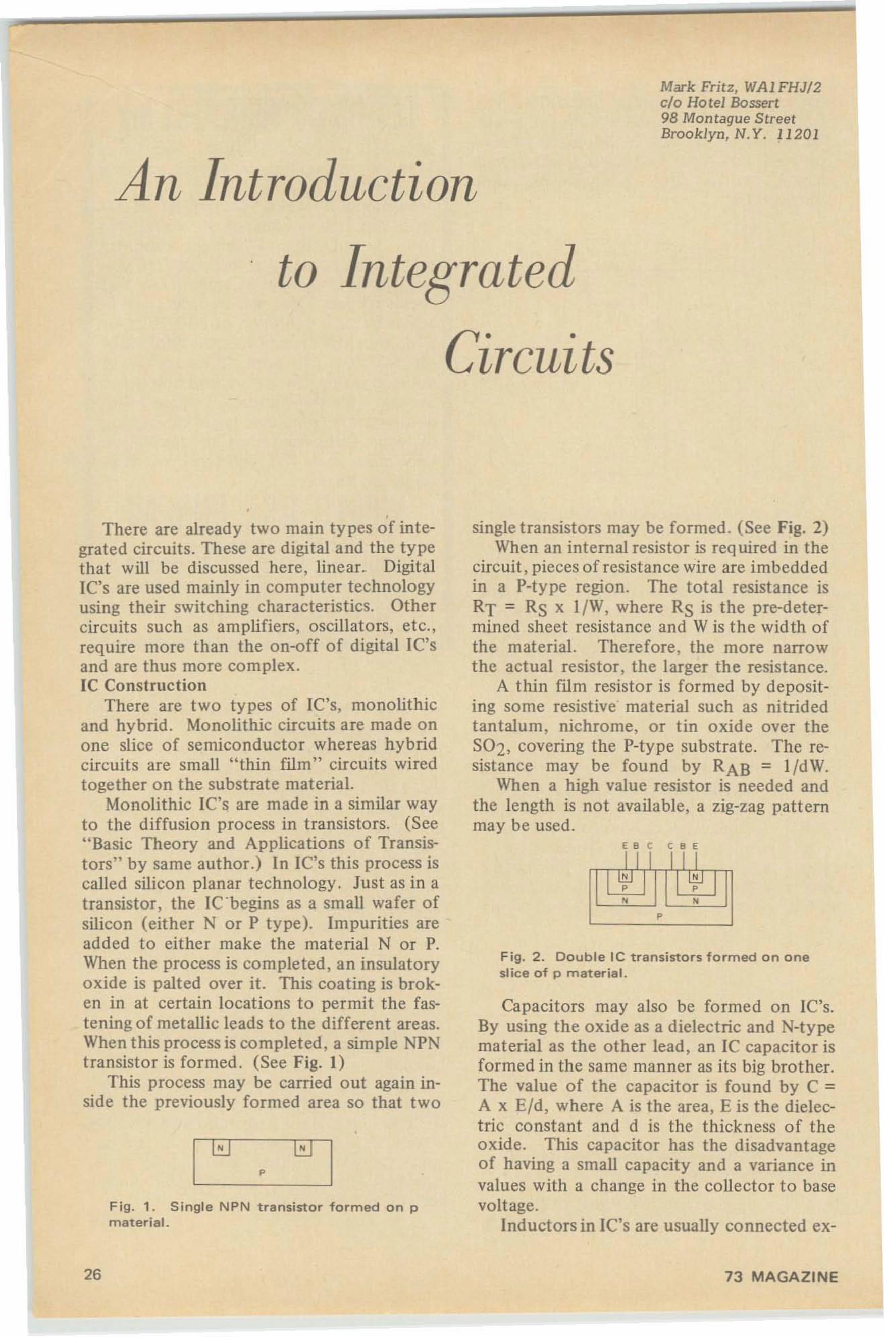
F ig .7 . The Super-regenerative Detector Inowout lawed because of radiatio n).
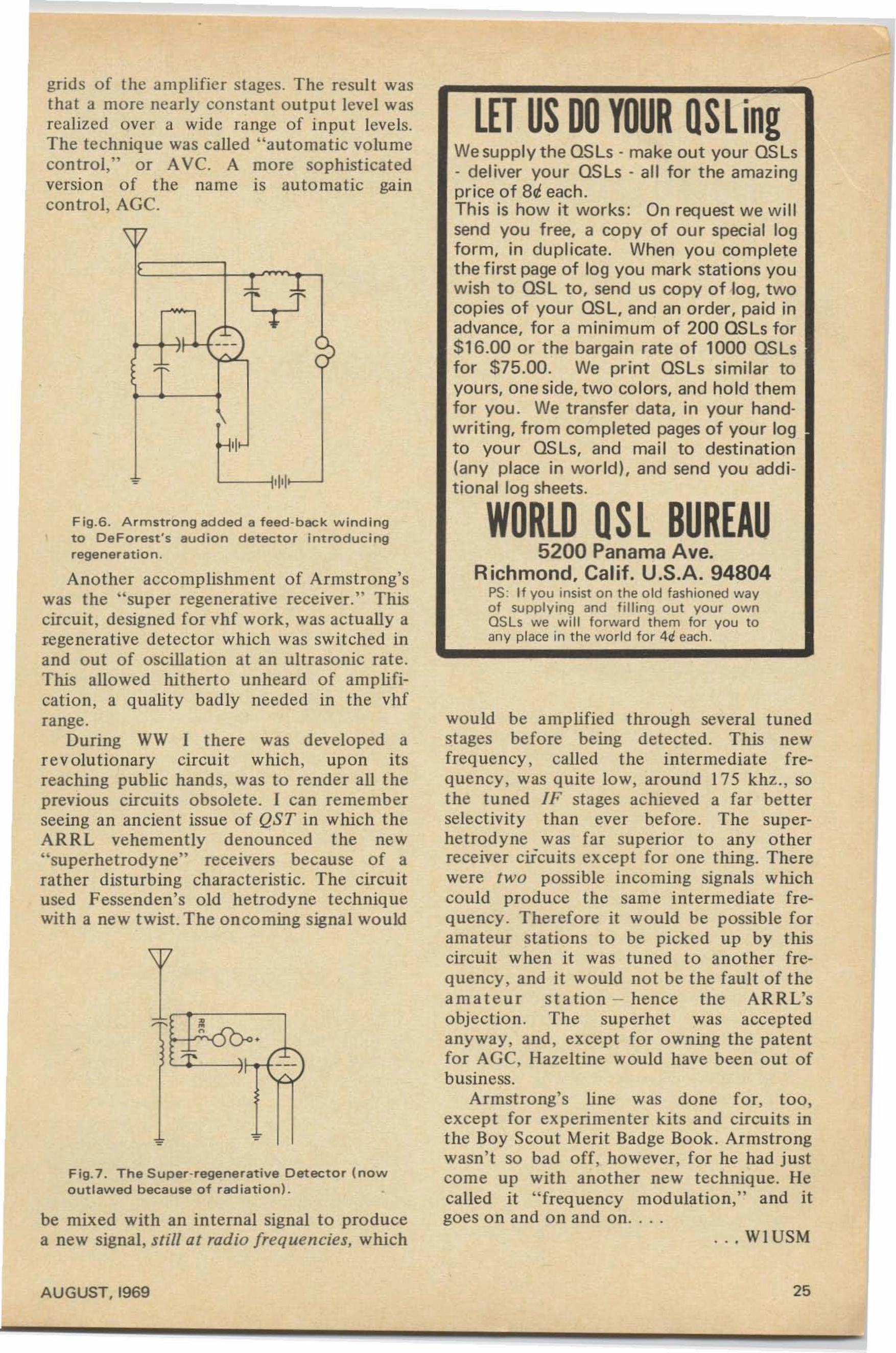
grids of the ampli fier stages. The result wasthat a more nearly constant output level wasrealized over a wide ra nge of in pu t levels.The technique was called "automatic volumecontrol," or Ave. A more sophisticatedversio n of the name is auto matic gaincontrol, AGe.
be mixed with an internal signal to producea new signal, still at radio frequencies, which
Another accomplishment of Armstrong'swas the "super regenerative receiver." Thiscircuit, designed for vhf work , was actually aregenerative detector which was swit ched inand out of oscillation at an ultrasonic rate.This allowed hit herto unheard of amplification, a quality badly needed in the vhfrange.
During WW I there was developed are volutio nary circuit which, upon itsreaching public hands, was to render all theprevious circuit s obsolete. I can rememberseeing an ancien t issue of QS T in which theARRL vehemently denounced the new"superhetrodyne" receivers because of arather disturbing characteristic. The circuitused Fessenden's old hetrodyne techniquewith a new twist. The oncoming signal would
Fig.G. Armstro ng added a teed-beck w in d ingto DeForest 's euc ton detector int roduc i ngregeneration .
\V
AUGUST, 1969 25
Mark Fritz, WAI FHJ/2clo Hotel Bossert98 Montague StreetBrooklyn, N .Y. 11201
An Introduction
to Integrated
Circuits
ES C C 8 E
I
: I ~,, ,,
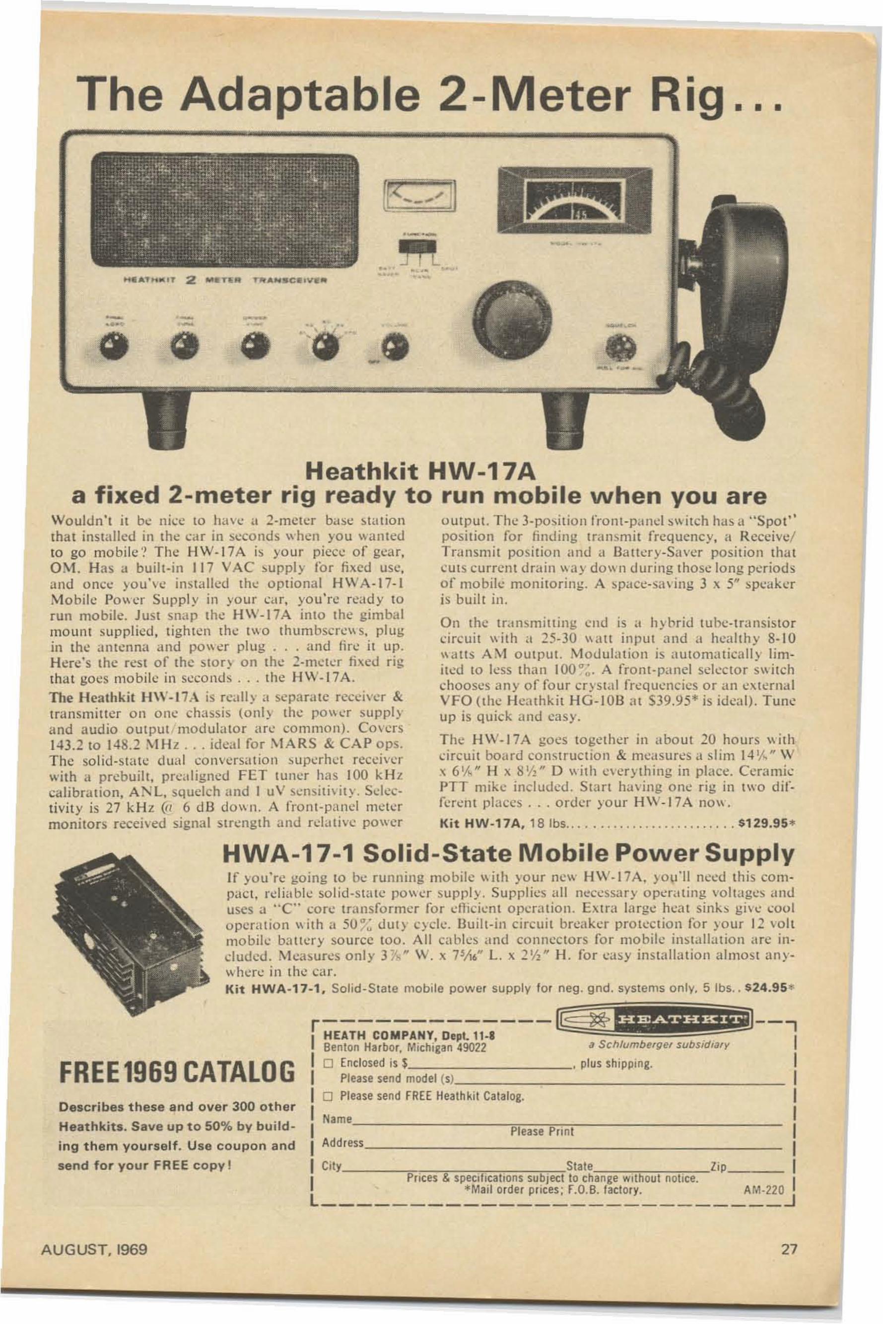
F ig. 2. Double Ie transistors formed on oneslice of p material.
single transistors may be formed . (See Fig, 2)When an internal resistor is required in the
circuit, pieces of resistance wire are imbeddedin a P-type region . The total resistance isRT = RS x l /W, where RS is the pre-determined sheet resistance and W is the wid th ofthe material. Therefore, the more narrowthe actual resistor, the larger the resistance.
A thin film resistor is formed by depositing some resistive' material such as nitridedtantalum, nichrome, or tin oxide over theS02, covering the P-type substrate. The resistance may be found by RAB = l /d W.
When a high value resistor is needed andthe length is not available, a zig-zag patternmay be used .
Capacitors may also be formed on Ie's.By using the oxide as a dielectric and N-typematerial as the other lead, an IC capacitor isformed in the same manner as its big brother.The value of the capacitor is found by C =A x E/d , where A is the area, E is the die lectric constant and d is the thickness of theoxide. This capacitor has the disadvantageof having a small capacity and a variance invalues with a change in the collector to basevoltage .
Inductors in IC's are usually connected ex-
,r_0J
,There are already two main types of inte
grated circuits, These are digital and the typethat will be discussed here, linear. Digitall'C's are used mainly in computer technologyusing their switching characteristics. Othercircuits such as amplifiers, oscillators, etc.,require more than the on-off of digital IC'sand are thus more complex.Ie Construction
There are two types of Ie's, monolithicand hybrid . Monolithic circuits are made o none slice of semiconductor whereas hybridcircuits are small "thin film" circuits wiredtogether on the substrate material.
Monolithic IC's are made in a similar wayto the diffusion process in transistors. (See"Basic Theory and Applications of Transistors" by same author.) In IC's this process iscalled silicon planar technology , Just as in atransistor , the Ie 'begins as a small wafer ofsilicon (either N or P type), Impurities areadded to either make the material N or P.When the process is completed, an insulatoryo xide is palted over it. This coating is broken in at certain locatio ns to permit the fastening of metallic leads to the different areas.When this process is completed, a simple NPNtransistor is formed , (See Fig, J)
This process may be carried out again inside the previously formed area so that two
Fig. 1. Single NPN transistor formed on pmaterial.
26 73 MAGAZINE
The Adaptable 2-Meter Rig ...
_.' ..• •
._.-~... ..••
•
- '- -_....~ - . - •-. .. - .-ct ct <t .~• •
_.._-
Heathkit HW-17Aa fixed 2-meter rig ready to run mobile when you are
Wouldn't it be nice to have u z-mcicr base sta uo nthat insta lled in the car in seconds when yo u wan tedto go mo bil e'! The HW.1 7A is your piece of gea r,O~t. Has a built-in 117 VAC supply to r fixed usc,and once you've Installed the o ptiona l HWA ·1 7-1Mobile Pow er Su ppl y in your car, you're ready torun mobile. J ust snap the HW-1 7A in to the gimba lmount supplied . t ighten the IWO thum bscrews. plugin the anten na and power plug ... a nd fi re it up .Here's the res t of the sto ry on the :!-ml,,'h:r ti xed rigthat goes mo bile in seconds ... the HW-1 7A .The Heathkit 11\\'-17.-\ is rcallv a separate receiver &:transmitter on one chassis (on ly rhc po wer supplya nd a udio o utpu t modulator arc common). Covers143.2 to 148.2 .\1H z ... ideal fo r \ IARS & C A P cps.The so lid-sta te d ua l conversa tion superhet receiverwith it prebui lt , prculigncd FET tuner has 100 k Hzcali bra tion , A:"L. squelch and I uV sensitivity . Sclcctivir y is 27 k Hz (0 6 d B dow n. A fro nt -panel metermonitors received signal strength and relative power
outpu t. T he 3-posi tion trent-panel sw itch hus it " SPOI"position for find ing tra ns mit frequency, a Recei ve/Transmit posi tio n and a Battery-Saver position thatCUts c urrent d rain way down du ring tho se long per iodsof mobile monitoring. A space-say ing 3 x 5H speakeris built in.
On the tra nsmit t ing end is a hybrid tube-transisto rci rcu it with <I 25-30 wa n inpu t and <l healt hy 8-10wat ts A:-.t ou tput. Mod ulat ion is a utomatica lly limited to less tha n 100 ",: . A fro nt-pa nel se lecto r switchchooses any of fou r crystal fre quencies o r an externa lVFO (the Hea thk it HG-I OB at S39.9 5* is ideal). Tuncup is quick and eas y.
T he HW-1 7A goes to gether in abo ut 20 hours wir hcircuit board construction & measu res ,I slim 14 1/~ H Wx 6 1A H H X ~W2H 0 with cverything in place. Cera micPTT mike included. Sta rt having one rig in two dif'fcrcn t places ... order yo ur H W- 17A no v .
Kit HW-17A. 18Ibs $129.9 5.
HWA-17-1 Solid-State Mobile Power SupplyIf you're going to be running mobile \\ ith yo ur new HW-1 7A. )' ou'H need this CO Ill
pac t, relia ble solid-sta te power sup ply . Supplies a ll necessary operat ing voltages anduses a "C" co re transformer fo r e ff icient operat ion. Ext ra la rge heat sin ks giw 1;00 1
operatio n wi th a 50 ~~ duty cycle. Built-i n ci rcui t breaker protectio n for yo ur I~ voltmob ile bat tc ry so urce too . A ll cables and connectors fo r mo bile ins tulkuion a rc ineluded. Measures only 3 1,," w . x 7~;i6" L. X 2 1/ 2
H H . for eas y ins ta lla tion a lmo st an ywhere in the ca r.Kit HWA-17-1. Solid-S tate mobile power supply for neg. gnd. systems only. 5 Ins.. $24.95.
d Schlumberger subsidldry
, plus shipping.
Please Pnnt
fG ~,~--.,rl~~;-CO,;;:AN;,-DePI~1~--- IBenton Harbor, Michigan 49022
I 0 Enclosed is $=;.;;I(-;;::======~:.::::'~_______ III Please send ~_odel (sJ
I 0 Please send FREE Heathkit Catalog. II Name II II Address II City . . . State . . l ip_ II Prices & speemcencns subject to change Without nonce. I
*Mail order prices; F.O.B. factory. AM·220L ~
FREE1969 CATALOGDescribes these and over 300 ot he rHeathkit• . Save up t o 50% by bu ild
ing them yourself. Use coupo n a nds e nd for your FREE COpy!
AUGUST, 1969 27
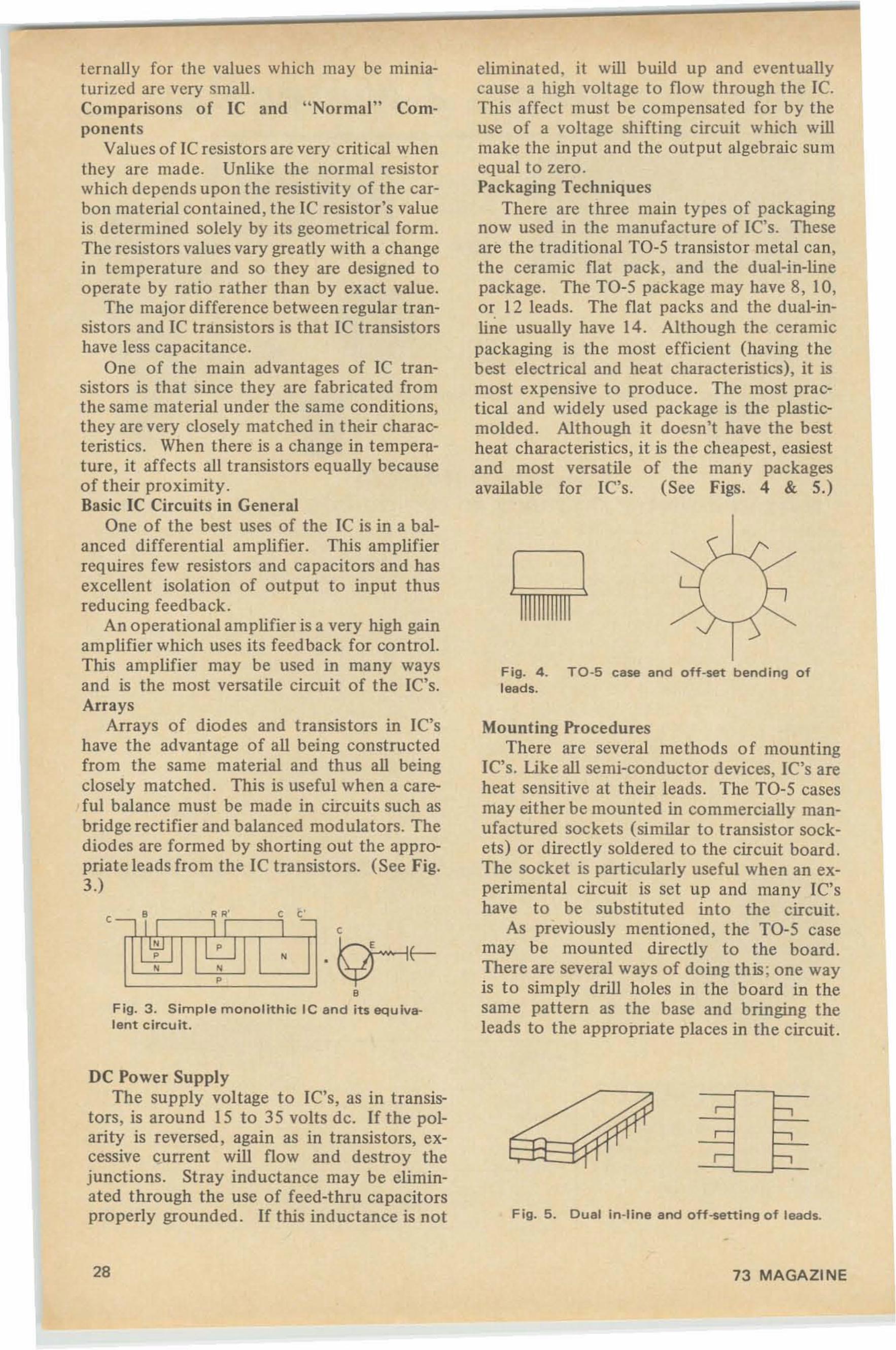
ternally for the values which may be miniaturized are very small .Comparisons of IC and "Normal" Components
Values of lC resistors are very critical whenthey are made. Unlike the normal resistorwhich depends upon the resistivity of the carbon material contained, the IC resistor's valueis determined solely by its geometrical form.The resistors values vary greatly with a changein temperature and so they are designed tooperate by ratio rather than by exact value.
The major difference between regular transistors and IC transistors is that IC transistorshave less capacitance.
One of the main advantages of IC transistors is that since they are fabricated fromthe same material under the same conditions,they are very closely matched in t heir characteristics . When there is a change in temperature, it affects all transistors equally becauseof their proximity.Basic Ie Circuits in General
One of the best uses of the IC is in a balanced differential amplifier. This amplifierrequires few resistors and capacitors and hasexcellent isolation of output to input thusreducing feedback.
An operational amplifier is a very high gainamplifier which uses its feedback for control.This amplifier may be used in many waysand is the most versatile circuit of the IC's.Arrays
Arrays of diodes and transistors in IC'shave the advantage of all being constructedfrom the same material and thus all beingclosely matched. This is useful when a careful balance must be made in circuits such asbridge rectifier and balanced mod ulators. Thediodes are formed by shorting out the appropriate leads from the IC transistors. (See Fig.3.)
Mounting ProceduresThere are several methods of mounting
Ie's. Like all semi-conductor devices, Ie's areheat sensitive at their leads. The TO-S casesmay either be mounted in commercially manufactured sockets (similar to transistor sockets) or directly soldered to the circuit board .The socket is particularly useful when an experimental circuit is set up and many IC'shave to be substituted into the circuit.
As previously mentioned, the TO-S casemay be mounted directly to the board .There are several ways of doing this ; one wayis to simply drill holes in the board in thesame pattern as the base and bringing theleads to the appropriate places in the circuit.
eliminated, it will build up and event uallycause a high voltage to flow through the Ie.This affect must be compensated for by theuse of a voltage shift ing circuit which willmake the input and the output algebraic sumequal to zero .Packaging Techniques
There are three main types of packagingnow used in the manufacture of Ie's. Theseare the traditional TO-S transistor metal can ,the ceramic flat pack , and the dual-in-linepackage. The TO-5 package may have 8, 10,or 12 leads. The flat packs and the dual-inline usually have 14. Although the ceramicpackaging is the most efficient (having thebest electrical and heat characteristics) , it ismost expensive to produce. The most practical and widely used package is the plasticmolded . Although it doesn't have the bestheat characteristics, it is the cheapest, easiestand most versatile of the many packagesavailable for Ie's. (See Figs. 4 & 5,)
Fig. 4 . TO-5 case and ott-set bending ofleads.
c
•
...•- I I I .-, ,, ,, ,,
•Fig. 3 . Simple monolithic Ie and its equIvalent circuit.
c
DC Power SupplyThe supply voltage to fC's, as in transis
tors , is around 15 to 35 volts de. Ifthe polarity is reversed. again as in transistors, ex·cessive current will flow and destroy thejunctions. Stray inductance may be eliminated through the use of feed-thru capacitorsproperly grounded. If this inductance is not Fig. 5 . Dual in-line and off-setting of leads.
28 73 MAGAZINE
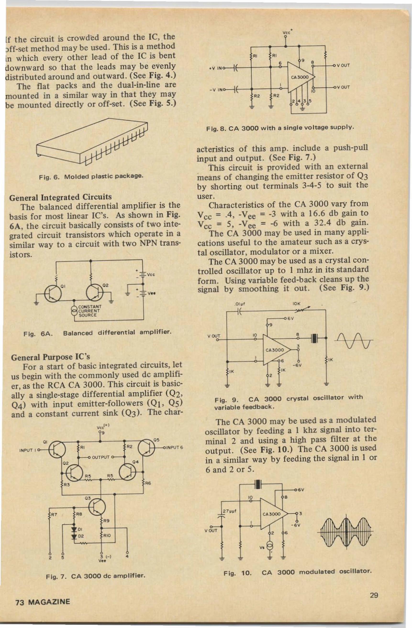
If the circuit is crowded around the IC, the)ff-set method may be used . This is a methodin which every other lead of the IC is bentdownward so that the leads may be evenlydist ributed around and out ward . (See Fig. 4.)
The flat packs and the dual-in-line aremounted in a similar way in that they maybe mounted directly or off-set. (See Fig. 5.)
•'"
Fig. 6 . Mo lded plastic package.
F ig. 6A. Balanced different ial amplif ier.f\ f\VV
•
'0'
- .
.01 11 1
,--1€-f.
ov
, '0 • ,If-<; ,, CA,/
, ,-ov
" "e
- -
'I',I r'0 •
27 11 11 1~
, CA?- sv
QVT , ,..
•, • -
The CA 3000 may be used a. a modulatedoscillator by feeding a I khz signal into terminal 2 and using a high pass filter at theout put. (See Fig. 10.) The CA 3000 is usedin a similar way by feeding the signal in I or6 and 2 or 5.
Fig. 9 . CA 3000 crysta l osci ll ator withva riable feedback.
Fig. 8 . CA 3 0 0 0 w ith a single vo ltage supply.
act eristics of this amp. include a push-pullinput and output. (See Fig. 7.)
This circuit is provided with an externalmeans of changing the emitter resistor of Q3by shorting out terminals 3-4-5 to suit theuser.
Characteristics of the CA 3000 vary fromVee = .4 , -Vee = -3 with a 16.6 db gain toVcc = 5, -Vee = -6 with a 32.4 db gain.
The CA 3000 may be used in many applications useful to the amateur such as a crystal oscillator, modulator or a mixer.
The CA 3000 may be used as a crystal controlled oscillator up to I mhz in its standardform. Using variable feed-back cleans up thesignal by smoothing it out. (See Fig. 9 .)
INPUT 6
",
•3 l-l...
,.,",
, ,
,~ 0'
" "~ OUTPUT
0' -s., ., 1/
" "0'
" " "0'0' "0
•- rl1 1-0' 0'
{. -!-. --
$ CONSTAI'lITCURRE "tTSOURC E
INPUT 1
General Purpose Ie'sFor a start of basic integrated circuits, let
us begin with the commonly used de amplifier, as the RCA CA 3000. This circuit is basically a single-stage differential amplifier (Q2,Q4) with input emitter-followers (Q I, Q5)and a constant current sink (Q3)· The char-
General Integrated CircuitsThe balanced differential amplifier is the
basis for most linear IC's. As shown in Fig.6A, the circuit basically consists of two integrated circuit transistors which operate in asimilar way to a circuit with t wo NPN transistors.
Fig. 7. CA 3000 de amp lif ier.Fig. 10. CA 3 0 0 0 modulated oscill ator.
73 MAGAZINE29
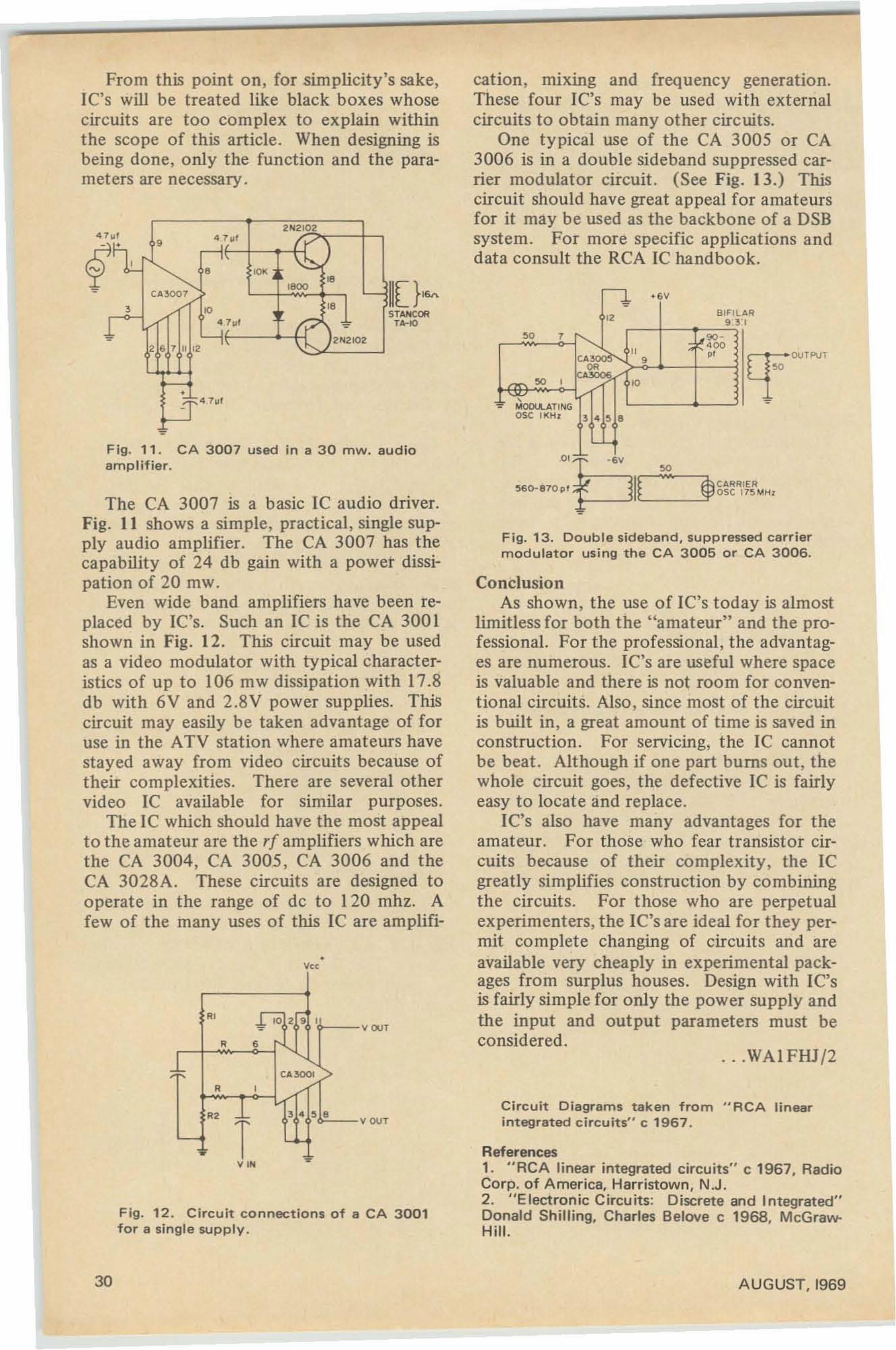
,
From this point on, for simplicity's sake,LC's will be treated like black boxes whosecircuits are too complex to explain withinthe scope of this article. When designing isbeing done, only the function and the parameters are necessary.
I ,VO~ 400, "
'* +6V
"
3 4 5 8
~ eo ,
~ MOOLl.AT INGOSC II(Hr
so
cation, mixing and frequency generation.These four IC's may be used with externalcircuits to obtain many other circuits.
One typical use of the CA 3005 or CA3006 is in a double sideband suppressed carrier modulator circuit. (See Fig. 13.) Thiscircuit should have great appeal for amateursfor it may be used as the backbone of a DSBsystem . For more specific applications anddata consult the RCA IC handbook.
2N210 2
,
•v"
Fig. 12. Circuit connections of a CA 3001for a single supply .
Fig. 11 . CA 3007 used in a 30 mw. audioamplifier.
The CA 3007 is a basic IC audio driver.Fig. It shows a simple, practical, single supply audio amplifier. The CA 3007 has thecapability of 24 db gain with a power dissipation of 20 mw.
Even wide band amplifiers have been replaced by IC's. Such an IC is the CA 3001shown in Fig. 12. This circuit may be usedas a video modulator with typical characteristics of up to 106 mw dissipation with 17.8db with 6V and 2.8V power supplies. Thiscircuit may easily be taken advantage of foruse in the ATV station where amateurs havestayed away from video circuits because oftheir complexities. There are several othervideo IC available for similar purposes.
The IC which should have the most appealto the amateur are the rf amplifiers which arethe CA 3004, CA 3005 , CA 3006 and theCA 3028A. These circuits are designed tooperate in the range of de to 120 mhz. Afew of the many uses of this IC are amplifi-
ConclusionAs shown, the use of IC's today is almost
limitless for both the "amateur" and the professional. For the professional, the advantages are numerous. IC's are useful where spaceis valuable and there is not room for conventional circuits. Also, since most of the circuitis built in, a great amount of time is saved inconstruction . For servicing, the IC cannotbe beat. Although if one part bums out, thewhole circuit goes, the defective IC is fairlyeasy to locate and replace.
IC's also have many advantages for theamateur. For those who fear transistor circuits because of their complexity, the ICgreatly simplifies construction by combiningthe circuits. For those who are perpetualexperimenters, the IC's are ideal for they permit complete changing of circuits and areavailable very cheaply in experimental packages from surplus houses. Design with IC'sis fairly simple for only the power supply andthe input and output parameters must beconsidered.
Circuit Diagrams taken from "RCA linearintegrated circuits" c 1967.
. . .WAIFHJ/2
"p" '"56l)-870p' I~'- m CARRIERL !f:' 0 s c 17 ~ MHz
•
Fig. 13. Double sideband, suppressed carriermodulator using the CA 3005 or CA 3006.
References1. "RCA linear integrated circuits" c 1967, RadioCorp. of America, Harristown, N.J .2. "Electronic Circuits: Discrete and Integrated"Donald Shilling. Charles Belove c 1968. McGrawHill.
veer
V OVT
•
" ~ 10 2 , ,• ,
<,<,
~ " """>• , /'
"'r
,."
30 AUGUST. 1969
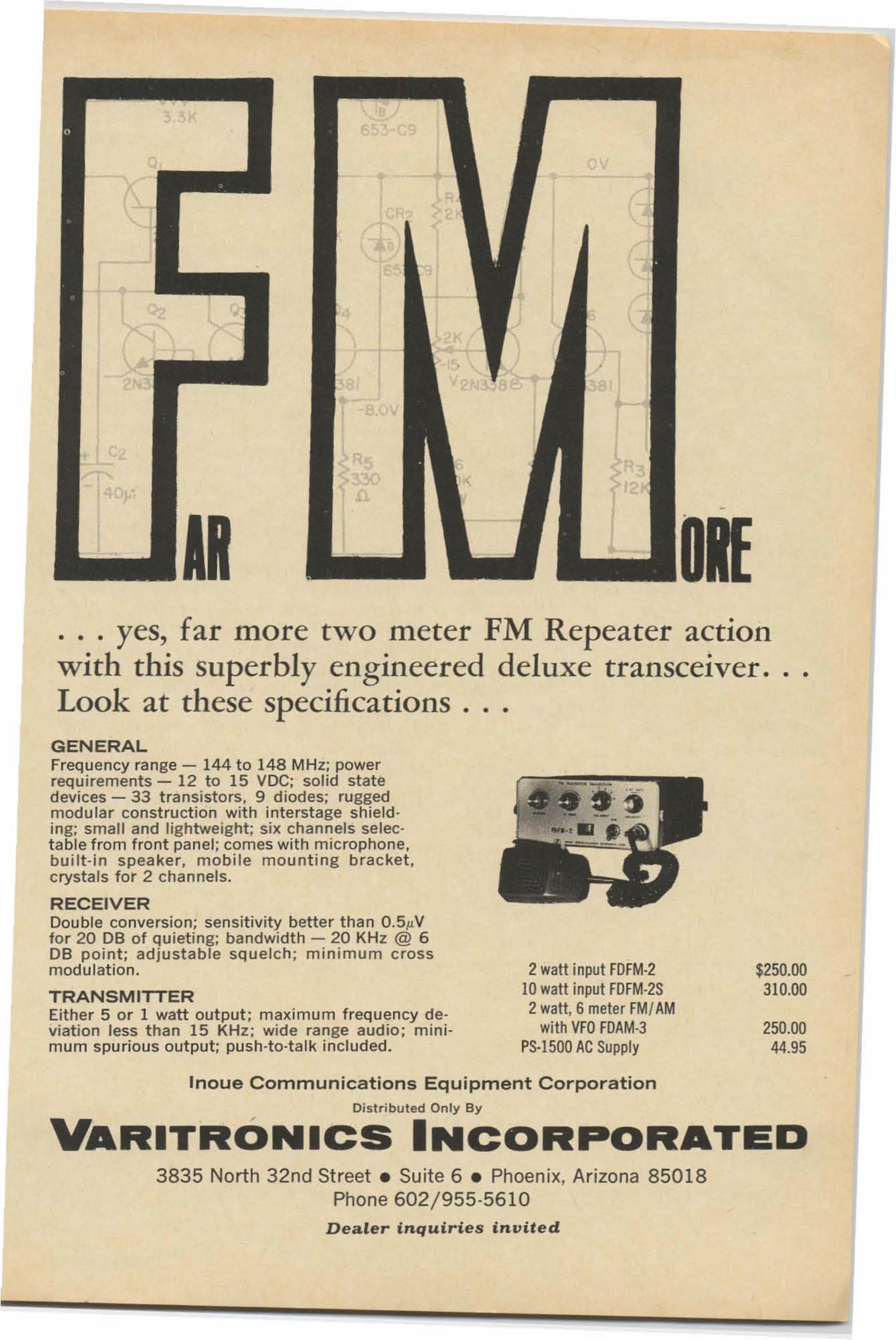
... yes, far more two meter FM Repeater actionwith this superbly engineered deluxe transceiver.Look at these specifications ...
• •
GENERALFrequency range - 144 to 148 MHz; powerrequirements - 12 to 15 VDC; solid statedevi ces - 33 transistors, 9 d iodes; ruggedmodu lar const ruct ion wi t h interstage shielding; sma ll and lightweight; six channe ls se lect able from front panel; com es wit h microphone.buil t -in spea ker, mobile mount ing bracket,crystals for 2 channels.
RECEIVERDouble convers ion; sensitivity better than O.5,uVfor 20 DB of quieti ng; bandwidth - 20 KHz @ 6DB point ; adjusta ble squelch; minimum crossmodulation.
TRANSMITTEREither 5 or 1 watt output ; maximum frequency deviation less t han 15 KH z ; wide ra nge aud io; m inimum spurious out put ; push-to-talk included.
2 watt input FOFM·210 watt input FOFM·2S2 watt, 6 meter FMI AM
with VFO FOAM·3PS·1500 AC Supply
$250.00310.00
250.0044.95
Inoue Communications Equipment CorporationDist r i buted Only By
VARITRONICS INCORPORATED3835 North 32nd Street. Suite 6 • Phoenix, Arizona 85018
Phone 602/955·5610Dealer i n q u i r ie s invited
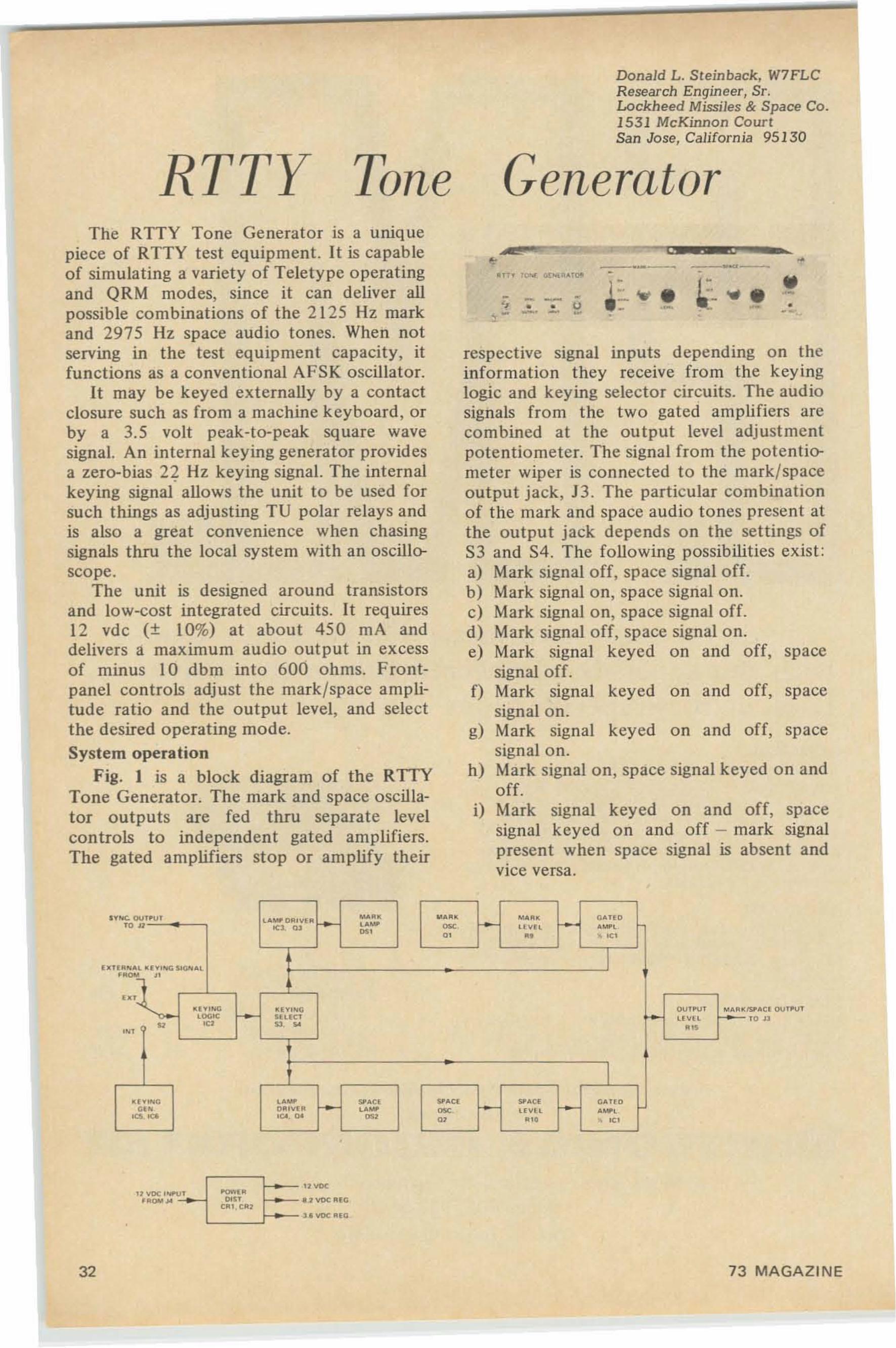
RTTY Tone
Donald L. Steinback, W7FLCResearch Engineer, Sr.Lockheed Missiles & Space Co.1531 McKinnon CourtSan Jose, California 95130
Generator
respective signal inputs depending on theinformation they receive from the keyinglogic and keying selector circuits. The audiosignals from the two gated amplifiers arecombined at the output level adjustmentpotentiometer. The signal from the potentiometer wiper is connected to the mark/spaceoutput jack, J3. The particular combinationof the mark and space audio tones present atthe output jack depends on the seltings ofS3 and S4. The following possibilities exist :a) Mark signal off, space signal off.b) Mark signal on, space signal on.c) Mark signal on, space signal off.d) Mark signal off, space signal on.e) Mark signal keyed on and off, space
signal off.f) Mark signal keyed on and off, space
signalon.g) Mark signal keyed on and off, space
signal on.h) Mark signal on, space signal keyed on and
off.i) Mark signal keyed on and off, space
signal keyed on and off - mark signalpresent when space signal is absent andvice versa,
The RTTY Tone Generator is a uniquepiece of RTTY test equipment. It is capableof simulati ng a variety of Teletype operatingand QRM modes, since it can deliver allpossible combinations of the 2125 Hz markand 2975 Hz space audio tones. When notserving in the test equipment capacity, itfunctions as a conventional AFSK oscillator.
It may be keyed externally by a contactclosure such as from a machine keyboard, orby a 3.5 volt peak-to-peak square wavesignal. An internal keying generator providesa zero-bias 22 Hz keying signal. The internalkeying signal allows the unit to be used forsuch things as adjusting TV polar relays andis also a great convenience when chasingsignals thru the local system with an oscilloscope.
The unit is designed around transistorsand low-cost integrated circuits. It requires12 vdc (+ 10%) at about 450 rnA anddelivers a maximum audio output in excessof minus 10 dbm into 600 ohms. Frontpanel controls adjust the mark/space amplitude ratio and the output level, and selectthe desired operating mode.System operation
Fig. I is a block diagram of the RTfYTone Generator. The mark and space oscillator outputs are fed thru separate levelcontrols to independent gated amplifiers.The gated amplifiers stop or amplify their
,.---
- - - ~." .. • tJ:i: - _. - , ,p
•.-~-~ " ..•
~~ f •... • ... • ••- - ••• --
ISJ'A" OUT.'"TO J1
OUT.UT CA.... ORIV' RMAR . " AR.
i-MAU - .,A UO
• 1<:1. 01 ..- = """._,
~. •• .. ...C U V, ,,,,, """AC• "" .n o,," . <Vo"., OU"UT MAR.
coo,e SUO " f- " " HU '" U • ..,
(W,,,,, ..- - SPACO SP ACI "'ACO r- <lAUD". DRO"OR ..- esc H " H ._,~ ,CoO . .,. ~, m ." • '"
•
..,"
,,~[~~~= "-11 "DC 'WU T' RDO' ''' .'VOCR'"
lIVOCR",
32 73 MAGAZINE
The Henry 2K-3 Linear Amplifier
F ive years ago the first 2K started spcaking for itself. Thc cn tirc amateur world hasgottc n the m cssage. The BIG, SHARP, CLEAN 2K signals have been passing them essage of quality sinc e that day. This is the wayan SSB signal should sound .Now after two model changes and as we approach the three thousand mark in the2 K series , thc message is even louder and clearer. Let us help you producethat same strong, clean signa l that you hear coming in fro m 2K owners the worldover. Come in , call , or write fo r literature describing the superb 2K-3 in detail.And then let us work out terms that will fi t you r budge t.The 2 K-3 (console or desk m odel) $745 .00
Henry Radio now has represen tat ives in different areas of the United States to simplify ordering for those livingnear one. Or you can order direct and we wi ll ship ... across the street or around the world. Call or write fordetai led specifications and term s.New York area: Cleveland area : Chicago area :JohnRichardt, W2WIY AIGross, W8PAl Bill Reynolds, K9ZXD
EASY FINAN CIN G · 10% DOWN O R TRADE-IN DO WN • NO FINANCE CHARGE IF
PAID IN 90 DA YS · GOOD RECONDITIONED APPARATU S . Nearl y a l l makes & models .Our reconditioned equ ipment carries a 15 day tr ial, 90 day warranty and may be t raded backwithin 90 days for full credi t toward th e purchase of NEW equipment. Wr ite for bullet in.
CAll DIR ECT • • • USE ARE A CO DE
11240 W_ Olympic, Los Angeles, Ca lif., 90064931 N. Euclid, Anaheim, Calif., 92801Butler, Missouri, 64730
213 477-6701714 772-9200816 679-31 27
"woito's l.argcst Dist ributor of Amateur Radio Equipment"
AUGUST , 1969 33
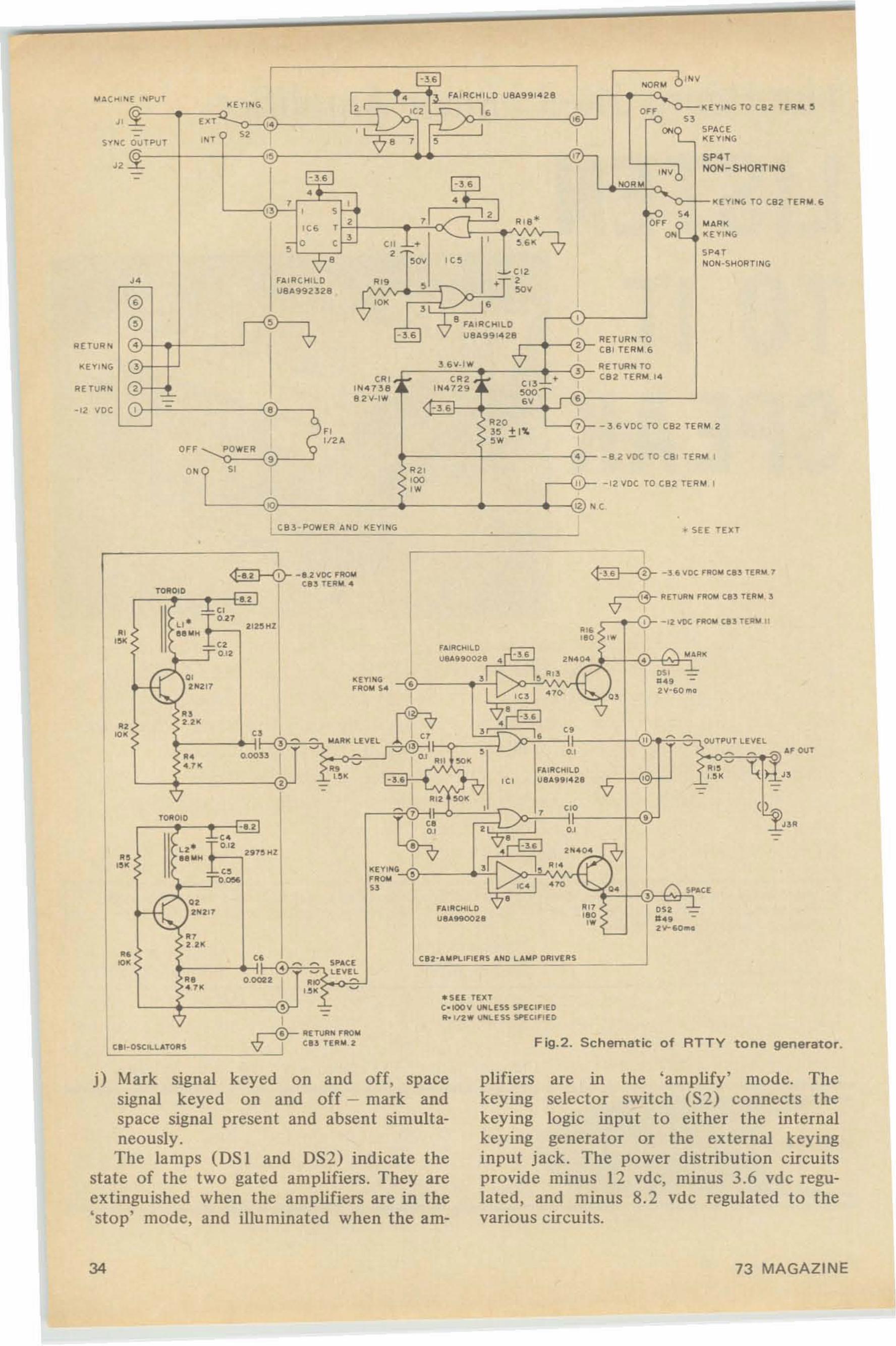
•
a
1( [ 1 1"10:;. TO C82 TE RM 6
PACE[ YI"'<;
['1""<; TO C82 TER'" ~
'"ON-SHORTING
P4TNON-SHORTING
I ~ 1 '".".t<' '<E ,",PUT
~ [ Y ING
I tr= A FAI"'CfoU L O U8 A9 9 1.ZB
,,~ 21 yC2 j IE.,
exr ~ "o~ "- sa '~ I T "" s-'O r OUTPUT '" e r , ,
n~ '" " s1NVb- -"- -a s ""..•r , • ,I"
, s , I k>_ ,.'" r
, A lB "' OF fON[
•,en L ,
'''~,
,- c c2 r;ov ,
<7 ' '" ,~~ 12
" IfA IR C HILD ." , . ,IUe ,l.g 92]2B ~,
@ ,7 10K
~' ~,
@ , 8 FA IR CHI L D- , (, UBA991428
? RETURN TO
• '-V -&~ e el TERM £>
~" 6\1- 1'" '" R[ l UIU. TO
'"' CR~ l' C R~ * • ~ CS2 T ERM I.ce
<.V I , L110 4 1 ] 8 ,"' 4 729 >00
'"~ ~ 8 2"'-1'" "~'" ~ -"6 """ ~~ ±1'L
-36\10( TO CS2 TE RM
~ ' f2Aor r <, POWER , • -B2VDCTOC B1 rEI'!'"
0- " ."00' " -12 VDC TO CB2 TE A'"ow
f,O\- ~S .. c
."
K [ 'I' I"I<;
-12 vee
IlE TUA"
I CB3-POWE R AND I(EYIN (i • SEE T[IlT
(
] f\ $"""C [
llSi • -b...2V-60...
/"\ I.U."l(•
I 0$1 -...2V"1;0 ",0
1•I
..""'",,w
Fig.2. Schematic of RTTY tone generator.
.Ut f[He- ee v l,IlrIl.-US 5,"E CIF IEO11. 112" UOlL E5 5 SPECIFIEO
1-
" $ P",'[• ~ ~
~ llV[l.-0 .002 2 I •• ~
'"~
, .=
"
"-~
"''""
..."
-1.2
-'-"• T Ol2" +_,2"5H2.e....f()lllO IQ
Yl~'~_~"2'1.,
'"
11(' • + t'l1II~ " +_, I I2S .. lII' ....
"t1;:~.) 2N2 17
....
","
",~
.,.,
...-<ir IIE TUIIOI FlIIO"
c::::::c::::::.:::.: -"V'-l t l5 TEll .. 2
plifierskeyingkeying
j) Mark signal keyed on and off, spacesignal keyed on and off - mark andspace signal present and absent simultaneously.The lamps (DS I and DS2) indicate the
state of the two gated amplifiers. They areextinguished when the amplifiers are in the'stop' mode, and illuminated when the am-
are ill the 'amplify' mode. Theselector switch (S2) connects thelogic input to either the internal
keying generator or the external keyinginput jack. The power distribution circuitsprovide minus 12 vdc, minus 3.6 vdc regulated, and minus 8.2 vdc regulated to thevarious circuits.
34 73 MAGAZINE
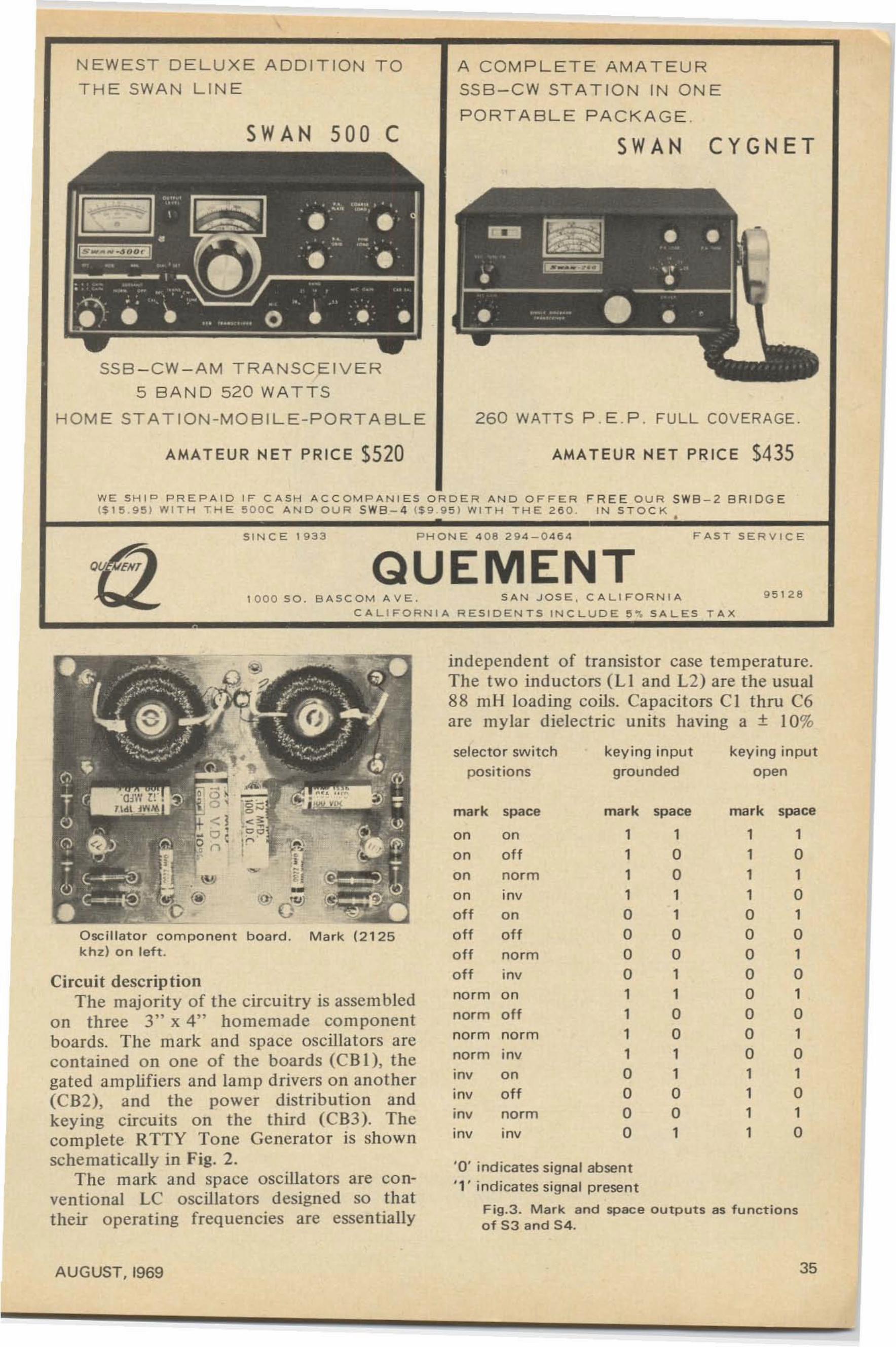
260 WATT S P . E . P . FUL L COV ERAG E.
CYGNETSWAN
AMATEUR NET PRICE S435
A C OM P L E T E AMATEUR
SSB-CW ST A T IO N IN ON E
P ORTABLE PA CKA GE .SWAN 500 C
N EWEST D E LUX E ADDIT ION T O
T H E SWA N L IN E
SSB -CW-A M T R A N SC E IVE R
5 BAND 520 WA T T S
H O ME STA TION -MO B IL E-PO R T A B L E
AMATEUR NET PRICE 5520
W E SH I ~ PR EPA ID IF CASH A CC OM PANIE S ORDER AN D OFF E R F REE O UR SW B - 2 BR I D GE($ 1 !i. 9 5) W ITH THE eooc A N D O UR S W8 - 4 ($ 9 951 WI T H THE 2 6 0 . I N S TOCK •
1 0 0 0 SO . B ASCOM A V E . S AN JOSE , C ALI FO R NI A
C AL IFORNIA RESID E N TS IN C L U D E 5 ". S AL ES T A X
S INCE 1 9 3 3 PHONE 4 0 8 294-046 4
QUEMENTF AST SERVICE
9 5 12 1:1
•
'0' i ndicates signal absent
"l indicates signal present
Fig.3. Mark and space outputs as functionso f 53 and 5 4.
independent of transistor case temperature.The tw o inducto rs (Ll and L2) are the usual88 mil loading coils. Capacitors C I thru C6are mylar dielectric units having a ± 10%
mark space
1o1o1o1o1o1o1o1o
1111oooooooo1111
key ing input
open
mark space
1oo11oo1
1oo11oo1
1111oooo1111oooo
keying input
grou nd ed
selecto r swi tch
pos it ions
IOV norm
IOV IOV
mark space
on on
o n o ff
on norm
on mvoff o n
off off
o ff norm
o ff IOV
norm on
norm o ff
norm norm
norm mv
mv o n
IOV off
-(fl' O '1J)
O scillator com p o nen t board . Mark (2125k hz) o n left.
Circuit descriptionThe majority of the circuit ry is assem bled
on three 3 " x 4" hom em ade com ponentboards. The mark and space oscillators arecontained on one of the boards (C BI ). thegated amplifiers and lamp drivers on another(C B2). and the power distribution andkeying circuits on the third (CB3). Thecomplete RTTY Tone Generato r is shownsche matically in Fig. 2.
The mark and space oscilla tors are conventional LC oscillators designed so thattheir opera ting frequencies are essent ially
AUGUST. 1969 35
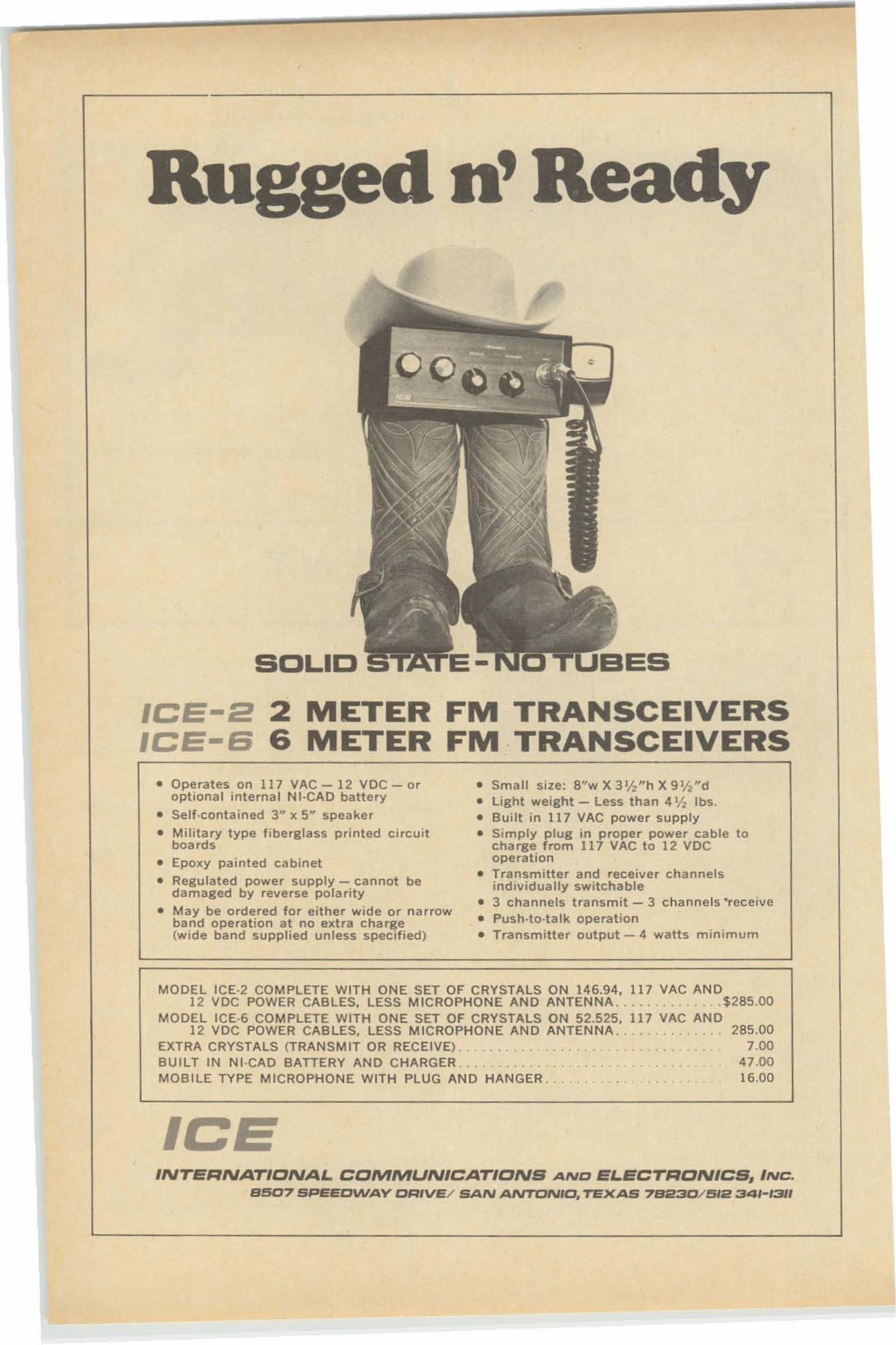
gedn' eady
SOLIO
ICE-2 2 METER FM TRANSCEIVERSICE-S 6 METER FM TRANSCEIVERS
• operates on 117 VAC - 12 VDC - or • Small size: 8"w X 3 112Hh X 9 V2"doptional interna l N I-CAD battery • light weight - Less than 4 % Ibs.
• sett-ccntalned 3" x 5" speaker • Bui lt in 11 7 VAC pow er supply
• Military type fibe rglass printed circuit • Simply plug in proper power cable 10boards charge f rom 117 VAC to 12 VDC
• Epoxy painted cabinet operation
• Regu lated power supply - cannot be • Transmitter and receive r channelsindividually switchabledamaged by reve rs e polarity
• 3 channe ls transmit - 3 c hannels "rec eive• May be ordered for either wide or narrowband operation at no extra charge • Pus h-ta -t a lk operation(wide band supplied unless speci fied) • T ra nsm itter output - 4 watts minimum
MODEL ICE-2 COM PLETE WITH ON E SET OF CRYSTALS ON 146.94. 117 VAC AND12 VDC POWER CABLES. LESS MICROPHONE AND ANTENNA ... . . . . . . .... $285.00
MODEL ICE·6 COMPLETE WITH ONE SET OF CRYSTA LS ON 52.525. 117 VAC AND12 VDC POWER CAB LES. LESS MICROPHON E AND ANTEN NA . . . . . .. . .. . 285 .00
EXTRA CRYSTALS (TRANSM IT OR RECEIVE) .. . . . . . . . • • .. . 7.00BUILT IN N t·CAD BATTERY AND CHA RGER .. . . . . . . . _ . . 47 .00MOBILE TYPE MICROPHONE WITH PLU G AND HANGER .. . . 16.00
ICEINTERNATIONAL. COMMUNICATIONS AND EL.ECTRON/CS. INC.
8507 SPEEDWAY OR'VE/ SAN ANTONIO, TEXAS 7S230/~I2 34'-'311
capacitance tolerance . Do not use ceramiccapac itors in any of the freq uency determining networks - ceramics are both temperature and voltage sensitive. Turns areremoved from Ll and L2 to adjust theoscillator frequencies to 21 25 /l z and 2975li z respectively. This will be discussed laterin the final adjustments. The capacitorvalues specified should resonate with any ofthe available "88 m H" ind uctors.
The mark and space gated amplifier andlamp driver cha nnels are identical. The marksignal from R9 is fed to one input of atwo-input NAND gate. lCI is a dual twoinput NAND gate. Po tentio meter R I I biasest his input (pin 5 of ICl ) so that the gate canoperate as a linear amplifier. The amplifiedmark signal appears at pin 6 of the gate aslong as pin 3 is at or near minus 3.6 vdc.When pin 3 of the gate is at or near ground,pin 6 of the gate is esentially connected topin 4 of t he gate and the mark signal outputat pin 6 disappears. The two-input logic gatethus provides a convenient means forswitching (or gating) and amplifying themark signal. The space channel fun ctions inexactly the same manner, utiliz ing the twoinput gate associated with pins I, 2, and 7 ofICI.
When terminal 6 of CB2 is at or nearground pote ntial, the mark signal outputfrom ICI is absent. Pin 3 of IC3 will also beat or near ground potential and the outputof IC3 (pin 5) will be at or near minus 3 .6Vdc. This voltage drives Q3 into conduction,extinguishing DS I. The whole procedu re isreversed when terminal 6 of CB2 is at ornear minus 3.6 Vdc ; the mark signal fromICI may be present (depending on thesetting of R9), the output of IC3 will be ator near ground potential, Q3 will not conduct, and DS I will illuminate. The spacelamp driver channel (IC4, Q4, and DS2)functions in exactly the same manne r, responding to keying signals at terminal 5 ofCB2. IC3 and IC4 are buffer amplifiers.Their sole function is to iso late the lampdriver circuits from the keying signals andassure complete switching of Q3 and Q4.
IC2 conditions the keying signal appliedto terminal 14 of CB3 . When the keyingsignal is at or near ground potential, terminal17 of CB3 is at or near minus 3.6 vdc andterminal 16 is at or near ground potential.Conversely, when the keying input at terminal14 is at or near minus 3.6 vdc (or opencircuited), terminal 17 is at or near groundpotential and terminal 16 is at or near minus
AUGUST . 1969
Incentive LicensingIs Here!
Brush up - Tone up - Shape upwith AMICO Technical Books
and code practice records.- - -
EASY TO UNDERSTAND BOOKS# 16·01 Advanced class license guide 50# 17·01 Ext ra class license guide .75Radio amateu r theory course. Latest editionis ideal for brushi ng up.# 102·01 (over 300 pages) 3.95
THE FASTEST AND SIMPLEST WAYTO INCREASE CODE SPEED ...
AMECO CODE PRACTICE RECORDS(33 1/ 3 RPM)
# 104·33 Contains material to increasecode speed from 13 wpm to 22 wpm 3.95# 106·33 19 to 24 wpm supplementto above 3.95
AND FOR THOSE OF YOUWHO ARE A BIT RUSTY
It 103·33 Contains material for 8 to 18 wpm.. 3.95# 105·33 supplement to above 3.95
AT LEADIN GHAM DISTRIBUTORS
--AMECO---DIVISION OF AEROTRON, INC.P. O. BOX 6527 • RALEIGH N. C. 2760B
37
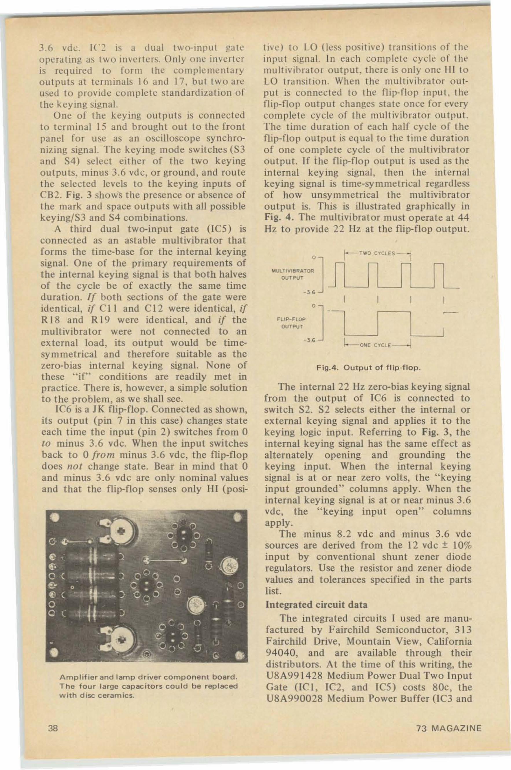
t ivc I to 1.0 (less positive ) transit ion s o f theinput signal. In each comp lete cy cle o f themult ivib rato r output. there is o nly o ne III toLO transit ion. When the mul tivi brat or ou tput is connected to the flip-flo p input, theflip-flop output changes state once for everycomplete cycle of the mult ivib ta tor ou tput.The time duration of each half cyc le o f theflip-flop outp ut is equal to the time durationof one complete cycle o f the multivib ratoroutput. If the flip-flop outpu t is used as theinternal keying signal, then the internalkey ing signal is time-symmetrical regardlesso f ho w unsy mmetrical the mult ivibratorou tpu t is. This is illustrated graphically inFig. 4. The mu lti vibrator must operate at 44lIz to provide 22 Hz at the flip-flo p ou tput.
-
~-ONE CYCLE---'
r- T WO CYCLES- i- r
-
Fig. 4 . Ou t p ut of flip -flo p .
o
o
FLIP· FLOP
OUTPUT
~ LlLT I V I B I'lA TOR
OUT PLI T
The internal 22 Hz zero-bias keying signalfrom the output of IC6 is co nnected toswitch S2. S2 selects either the internal orexternal keying signal and ap plies it to thekeying logic input. Referring to Fig. 3, theinternal keying signal has the same effect asalternately o pe ning and grounding t hekeying input. When the internal keyingsignal is at or near zero volts, the "keyinginput grounded" co lu mns apply. When theinternal keying signal is at or near minus 3.6vdc, the "keying input open" colum nsapply.
The minus 8.2 vdc and minus 3.6 vdcsources are derived from the 12 vdc + 10%input by conventional shunt zener dioderegulators. Use the resistor and zener diodevalues and tolerances specified in the partslist.Integrated circuit data
The integrated circuits I used are manufactured by Fairchild Semicond uctor, 31 3Fairchild Drive, Mountain View, California94040, and are available through theirdistributors. At the time of this writing, theU8A99 1428 Medium Po wer Dual Two In putGate (lC I, IC2, and IC5) costs 80c, theU8A990028 Medium Power Buffer (lC3 and
3. h vd c, IC2 is a dual t wo- inpu t gateope rating as two inverters. Only one inverteris required to form the com pleme ntaryoutputs at terminals 16 and 17, but two arcused to provide co mp le te standardization ofthe keying signal.
One of the keying outputs is connec tedto terminal 15 and brought out to the frontpan el for usc as an osci lloscope synchronizing signal. The key ing mode switches (S 3and S4) select either of the two keyingoutputs. minus 3.6 vdc , or ground, and routethe selec ted levels to the keying inputs ofCB2. Fig. 3 sho ws the presence or absence ofthe mark and space outputs with all possiblekeying/S 3 and S4 combinations.
A third dual two-input gate (IC5) isconnected as an astab le multivibrator thatforms the time-base for the internal keyingsignal. One of the primary requirements ofthe internal keying signal is that both halvesof the cycle be of exactly the same timeduration. If both sections of the gate wereiden tical, if C I I and Cl2 were identical, ifR 18 and R 19 were iden t ical, and if themultivibrator were not connected to anexternal load , its output would be tim esymmetrical and therefore suitable as thezero-bias internal keying signal. None ofthese "if" conditions are readily met inpractice. There is, however, a simple solutionto the problem, as we shall see.
IC6 is a J K flip-flop . Connected as shown,its output (pin 7 in this case) changes sta teeach time the input (pin 2) switches from 0to minus 3.6 vdc. When the input switchesback to 0 from minus 3.6 vdc, the flip- flopdoes not change state. Bear in mind that 0and minus 3.6 vdc are only nominal valuesand that the flip-flop senses only HI (posi-
Amplifier and lamp driver component board.The f our large capacitors cou ld be replacedwith d isc ceram ics.
38 73 MAGAZINE
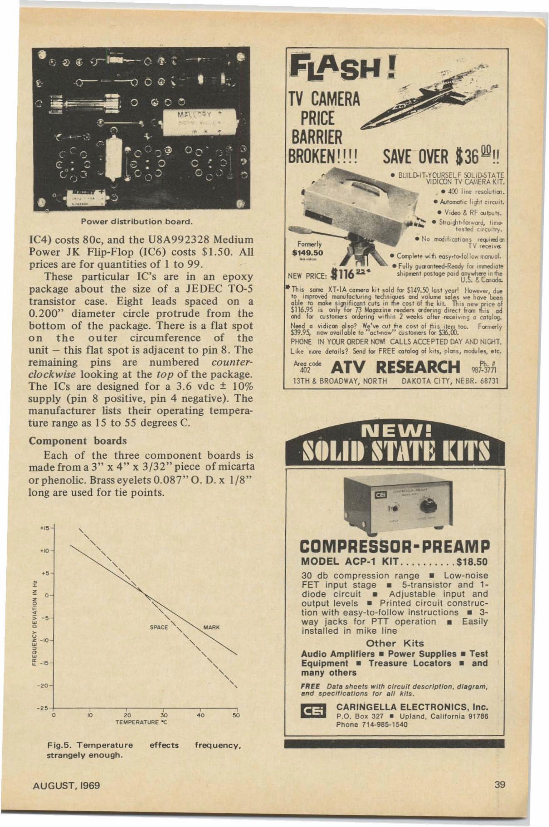
J'- '
• BUlLD-It·YOURSEl F SOLID-STATEVIDICON TV (N.',ERA KlT.•
•
For.--Iy$149.50~-
• • .tOO lin\' ' eso"'I'''' '• Auloma1,,: I,"'I Clrcu. l.• Video oS RF OIJlplJ ls.
• Slfoig,I. lorw(l'd, t,metested circui ll)' .
• No lflCId ,fiOlt,Ofu req..o, lt!d ",TV receive.
• Cllr11lle1e will, eoosy.to>lollowm<I~ ol.
• FlIlIy g\lCl'a1 teoed·Ready Ie. irrotoed 'oteshipment pos toge pnd O"k'''''' IR in ri.e
U. ::>. t. (c:nodo.
Th is seee XT·1 A ( 0'-'0 ~ 'I sold Ie. $149.50 losl year! HO-"ff, d...e10 ilJ1lroved monuloclunng ted:nil]Ju and volume $<lIes ...e hO\le ~nable 10 mo~e $ i ~iIICllf1 1 (lIls .in fie (osl of the ~ i l. Th is newprice 01$116.95 IS only lor 73 Mogazll'1e readers o dff.ng direcl from this oelom! fa cu slOl'T1erS adering ... ith in 2 ...eeks oltet ·rece,vino; a cOlolO9.
Need a vidiccn al so? We've ev t the cost 01 this I tem 100. former ly$39.95, now available 10 ..cct-ee... .. cusfomers lot SlS.OO.PHONE IN YOJR ORDER NO'tIr1 CALLS ACCEPTED DAY AND NIGHT.li~e nlOt!! eleloils? Send lor FRE E Qllolog 01 kilS, plal s, rnod."les. etc.
"'1Of''' ATV RESEARCH "j.';,A13TH oS BROADWAY, NORTH DAKOTA CI TY, NE BR. 6873\
COMPRESSOR-PREAMPMODEL ACP·1 KIT .. •••••.. • $18.50
30 db compression range _ Low-noiseFET input stage _ 5-trans istor and 1~
diode ci rcu it _ Adjustable input andoutput levels - Printed c ircuit co nstruc tion with easy-to-fo llow instruct ions _ 3·way jacks for PTT operation _ Easilyinsta lled in mike line
Other KitsAUdio Amplifiers _ Power Supplies _ TestEquipmenl _ Treasure Locators _ andmany others
FREE DBtB sh eets with c lrcui! dBscr/ptlon, d i agram,and spec ificat ions for all Il/ls .
NEW PRICE, .116 ...•
,FIf\SH !TV CAMERA
PRICEBARRIER
BROKEN!!! !
"-,"
SPACE "
"-"-,,-,
"-,-,
-,-,,
-,
· ' 0
Power d istribution board.
'"
IC4) costs 80c, and the U8A992328 MediumPower JK Flip-Flop (IC6) costs $1.50. AUprices are for quantities of I to 99 .
These particular Ie's are in an epoxypackage about the size of a JEDEC TO-5transistor case. Eight leads spaced on a0.200" diameter circle protrude from thebottom of the package. There is a flat spoton the outer circumference of theunit - this flat spot is adjacent to pin 8. Theremaining pins are numbered counterclo ckwise looking at the top of the package.The ICs are designed for a 3. 6 vdc + 10%supply (pin 8 positive. pin 4 negative). Themanufacturer lists their operating temperature range as 15 to 55 degrees C.
Component boardsEach of the three comoonent boards is
made from a 3" x 4" x 3/32" piece of micartaor phenolic. Brass eyelets 0.087" O. D. x 1/8"long are used for tie points.
CARING ELLA ELECTRONICS. Inc•p.o. BOl( 327 • Uplan d, Ca lifo rnia 91786Phone 714-985-1540
' 0' 0 soTE ~PERAT URE "C
o.,, -!----.---,.-- -,.---r-- ---,
Fig.5. Temperaturestrangely enough.
effects frequency,
AUGUST, 1969 39
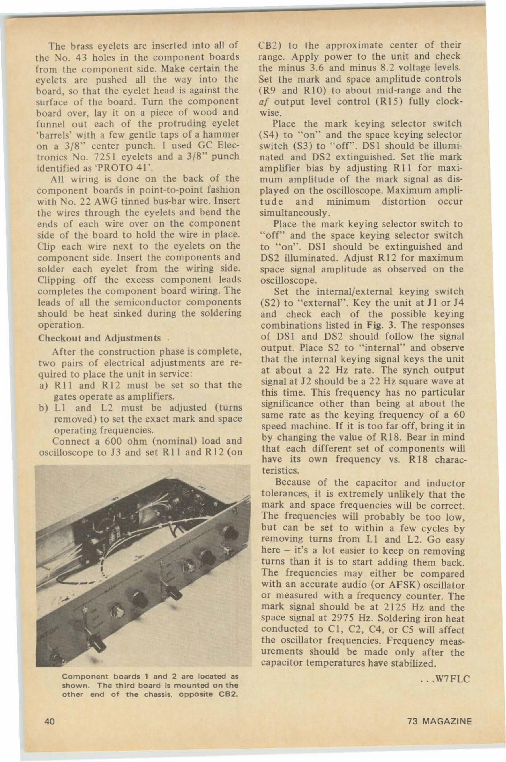
The brass eyelets are inserted into all ofthe No. 4 3 holes in the co mpo nent boardsfrom the com ponent side. Make certain theeyelets are pu shed all the way into theboard , so that the eye let head is against thesurface of the board . Turn the componentboard over, lay it on a piece of wood andfunn el out each of the protruding eyelet'barrels' with a few gentle taps of a hammeron a 3/8" ce nte r punch. I used GC Elect ronics No. 725 1 eyelets and a 3/8" punchidentified as 'PROTO 41 '.
All wiring is done o n the back of theco mpo nent boards in point-to-point fashionwith No. 22 AWG tinned bus-bar wire. Insertthe wires through the eyelets and bend theend s of each wire over on the componentside of the board to hold the wire in place .Clip each wire next to the eyelets on thecomponent side. Insert the components andsolder each eyelet from the wiring side .Clipping off the excess component leadscompletes the component board wiring. Theleads of all the semiconductor componentsshould be heat sinked during the solderingoperation.Checkout and Adjustments '
After the construc tion phase is complete,tw o pairs o f electrical adjustments are required to place the unit in service:a) R II and R 12 must be se t so that the
gates operate as amplifiers.b) L1 and L2 mu st be adjusted (turns
rem oved) to set the exact mark and spaceoperating frequencies.Connect a 600 ohm (nominal) load and
oscilloscope to 13 and set R II and R 12 (on
Component boards 1 and 2 are located asshown. The third board is mounted on theother end of the chassis, opposite CB2.
40
CB2) to the approximate center of theirrange. Apply power to the unit and checkthe minus 3.6 and minu s 8. 2 voltage levels.Set the mark and space amplitude controls(R9 and RIO) to about mid-range and theof o ut pu t level control (RI5) fully clockWIse.
Place the mark keying selec tor switch(S4) to "on" and the space keying selectorswitch (S3) to "off". OSI should be illuminated and OS2 ex tinguished. Set the markamplifier bias by adjusting R 11 for maximum amplitude of the mark signal as displayed on the oscilloscope. Maximum amplitude and minimum distortion occursimultaneously.
Place the mark keying selector switch to"off" and the space keying selector switchto "on". OS I should be extinguished andOS2 illuminated . Adjust R 12 for maximumspace signal amplitude as observed on theoscilloscope.
Set the in ternal/external keying switch(S2) to "external" . Key the unit at J I or J4and check each of the possible keyingcombinations listed in Fig . 3. The responsesof OS I and OS2 should follow the signaloutput. Place S2 to "internal" and observethat the internal keying signal keys the unitat about a 22 Hz rate. The synch outputsignal at 12 should be a 22 Hz square wave atthis time. This frequency has no particularsign ificance other than being at about thesame rate as the keying frequency of a 60speed machine. If it is too far off, bring it inby changing the value of R 18. Bear in mindthat each different set of components willhave its own frequency vs. R 18 characteristics.
Because of the capacitor and inductortolerances, it is ex tremely unlikely that themark and space frequencies will be correct.The frequencies will probably be too low,but can be set to within a few cycles byremoving turns from L I and L2. Go easyhere - it's a lot easier to keep on removingturns than it is to start adding them back .The frequencies may either be comparedwith an accurate audio (or AFSK) oscillatoror measured with a frequency counter. Themark signal should be at 2125 Hz and thespace signal at 2975Hz. Soldering iron heatconducted to C I, C2, C4, or C5 will affectthe oscillator frequencies. Frequency rneasurements should be made only after thecapacitor temperatures have stabilized.
. . .W7FLC
73 MAGAZINE
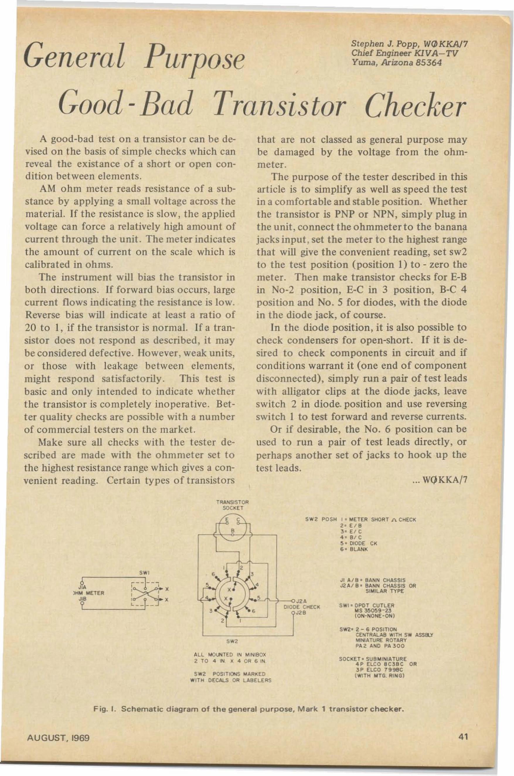
General Purpose
Good -Bad Transistor
Stephen J. Popp, WQJKKA/7Chief Engineer KIVA-TVYuma, Arizona 85364
CheckerA good-bad test on a transistor can be de
vised on the basis of simple checks which canreveal the existance of a short o r open condition between elements.
AM ohm meter reads resistance of a substance by applying a small voltage across thematerial. If the resistance is slow, the appliedvoltage can force a relatively high amount ofcurrent through the unit. The meter indicatesthe amount of current on the scale which iscalibrated in ohms.
The instrument will bias the transistor inboth directions. If forward bias occurs, largecurrent flows indicating the resistance is low.Reverse bias will indicate at least a ratio of20 to I, if the transistor is normal. If a transistor does not respond as described , it maybe considered defective. However, weak units,or those with leakage between elements,might respond satisfactorily . This test isbasic and only intended to indicate whetherthe transistor is completely inoperative. Better quality checks are possible with a numberof commercial testers on the market.
Make sure all checks with th e tester described are made with the ohm meter set tothe highest resistance range which gives a convenient reading. Certain types of transistors
TRANSISTORSOCKET
that are not classed as general purpose maybe damaged by the voltage from the ohmmeter.
The purpose of the tester described in thisarticle is to simplify as well as speed the testin a comfo rtable and stable position. Whetherthe transistor is PNP or NPN, simply plug inthe unit, connect the ohmmeter to the bananajacks input , set the meter to the highest rangethat will give the convenient reading, set swlto the test position (position I) to - zero themeter. Then make transistor checks for E-Bin No-2 position, E-C in 3 position, S-C 4position and No.5 for diodes, with the diodein the diode jack, of course.
In the diode position, it is also possible tocheck condensers for open-short. If it is desired to check components in circuit and ifconditions warrant it (one end of componentdisconnected), simply run a pair of test leadswith alligator clips at the diode jacks, leaveswitch 2 in diode. position and use reversingswitch 1 to test forward and reverse currents.
Or if desirable, the No.6 position can beused to run a pair of test leads directly, orperhaps another set of jacks to hook up thetest leads.
... WQKKA/7
SW2 POSH " METER SHORT J'\ CHECK2 ' EI B3- EI C4_ 9 1 C~. DIODE CK6' BLANK
sw,,nIno:~'
L --=.~:..:J--t~ ::T_ f X
d a, I s
sw'ALL '-'OUNTEO IN MINI80X2 TO 4 IN X 4 OR 6 IN
SW2 POSITIONS MARIl EDWITH DECAlS DR l ABELE RS
".DIODE Cl-iECK
.ee
Jt AI B . BANN CHASSISJ2 A/ B· BANN CHASSIS OR
SIMILAR TYPE
SWl o OPOT CUTLER..SM~9-23
(ON-NONE-ON)
SW2' 2 - 6 POSITIONCENTRALA8 Wlnt SW ASSEO"'MA1\IR£ ROTARYPA 2 ANO PA 30 0
SOCKET - SU BMINIATURE4P ELCO BC3B C OR3P ELCO 79geC(WITH IrIlTG. RI""Gl
AUGUST, 1969
Fig. J. Schematic diagram of the general purpose, Mark 1 transistor checker.
41
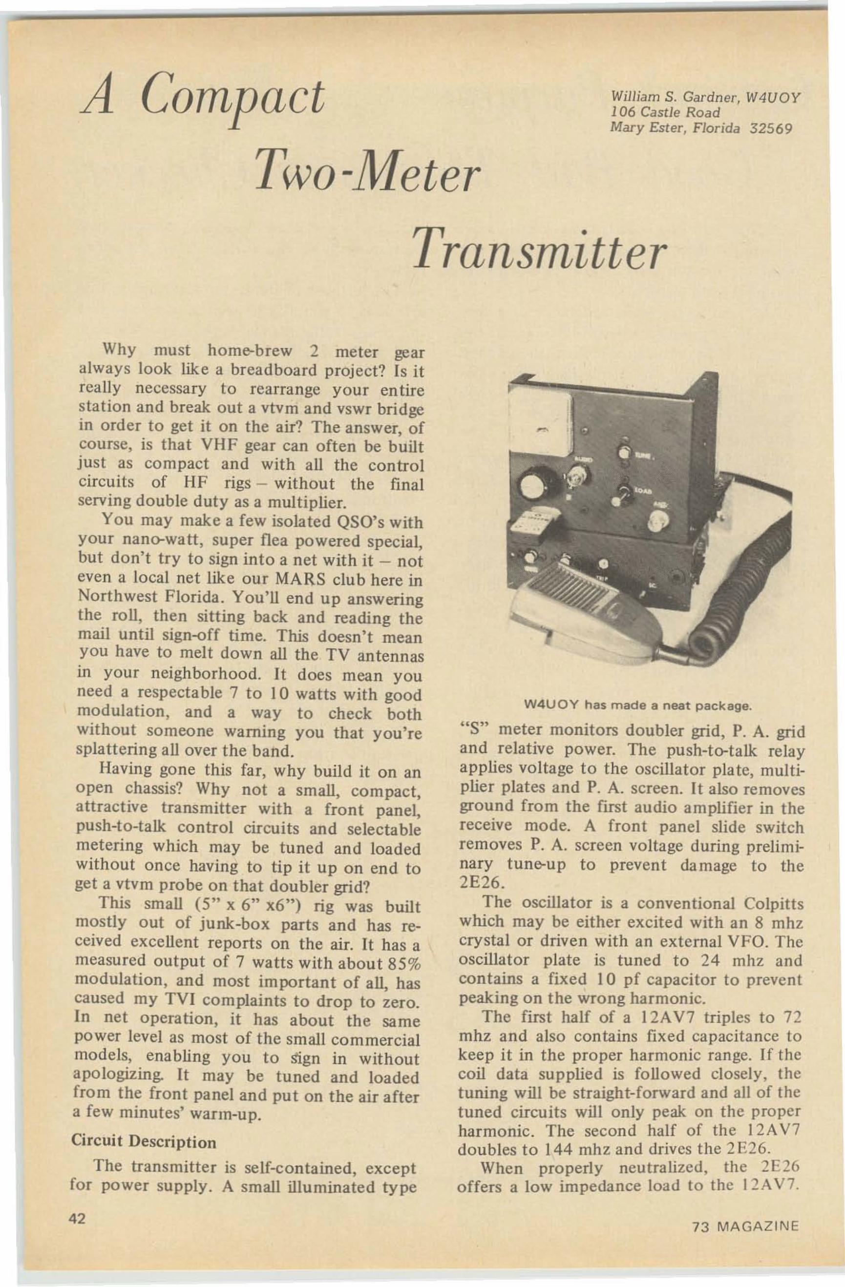
A Compact
Two-Meter
WjJljam S. Gardn er, W4UOY106 Castle RoadMary Ester, Florida 32569
Transmitter
Why must home-brew 2 meter gearalways look like a breadboard project? Is itreally necessary to rearrange your entirestation and break out a vtvrn and vswr bridgein order to get it on the air? The answer, ofcourse, is that VHF gear can often be builtjust as compact and with all the controlcircuits of HF rigs - without the finalserving double duty as a multiplier.
You may make a few isolated QSO's withyour nano-watt, super flea powered special,but don't try to sign into a net with it - noteven a local net like our MARS club here inNorthwest Florida. You'll end up answeringthe roll, then sitting back and reading themail until sign-off time. This doesn't meanyou have to melt down all the TV antennasin your neighborhood. It does mean youneed a respectable 7 to 10 watts with goodmodulation, and a way to check bothwithout someone warning you that you'resplattering all over the band.
Having gone this far, why build it on anopen chassis? Why not a small, compact,attractive transmitter with a front panel,push-to-talk control circuits and selectablemetering which may be tuned and loadedwithout once having to tip it up on end toget a vtvm probe on that doubler grid?
This small (5" x 6" x6") rig was builtmostly out of junk-box parts and has received excellent reports on the air. It has ameasured output of 7 watts with about 85%modulation, and most important of all, hascaused my TVI complaints to drop to zero.In net operation, it has about the samepower level as most of the small commercialmodels, enabling you to Sign in withoutapologizing. It may be tuned and loadedfrom the front panel and put on the air aftera few minutes' warm-up.
Circuit Description
The transmitter is self-contained, exceptfor power supply. A small illuminated type
42
W4UOY has made a neat package.
"S" . dmeter momtors oubler grid, P. A. gridand relative power. The push-to-talk relayapplies voltage to the oscillator plate, multiplier plates and P. A. screen. It also removesground from the first audio amplifier in thereceive mode. A front panel slide switchremoves P. A. screen voltage during preliminary tune-up to prevent damage to the2E26.
The oscillator is a conventional Colpittswhich may be either excited with an 8 mhzcrystal or driven with an external VFO. Theoscillator plate is tuned to 24 mhz andcontains a fixed 10 pf capacitor to preventpeaking on the wrong harmonic.
The first half of a I 2AV7 triples to 72mhz and also contains fixed capacitance tokeep it in the proper harmonic range. If thecoil data supplied is followed closely, thetuning will be straight-forward and all of thetuned circuits will only peak on the properharmonic. The second half of the 12AV7doubles to 144 mhz and drives the 2 E26.
When properly neutralized, the 2E26offers a low impedance load to the 12A V7.
73 MA GAZIN E
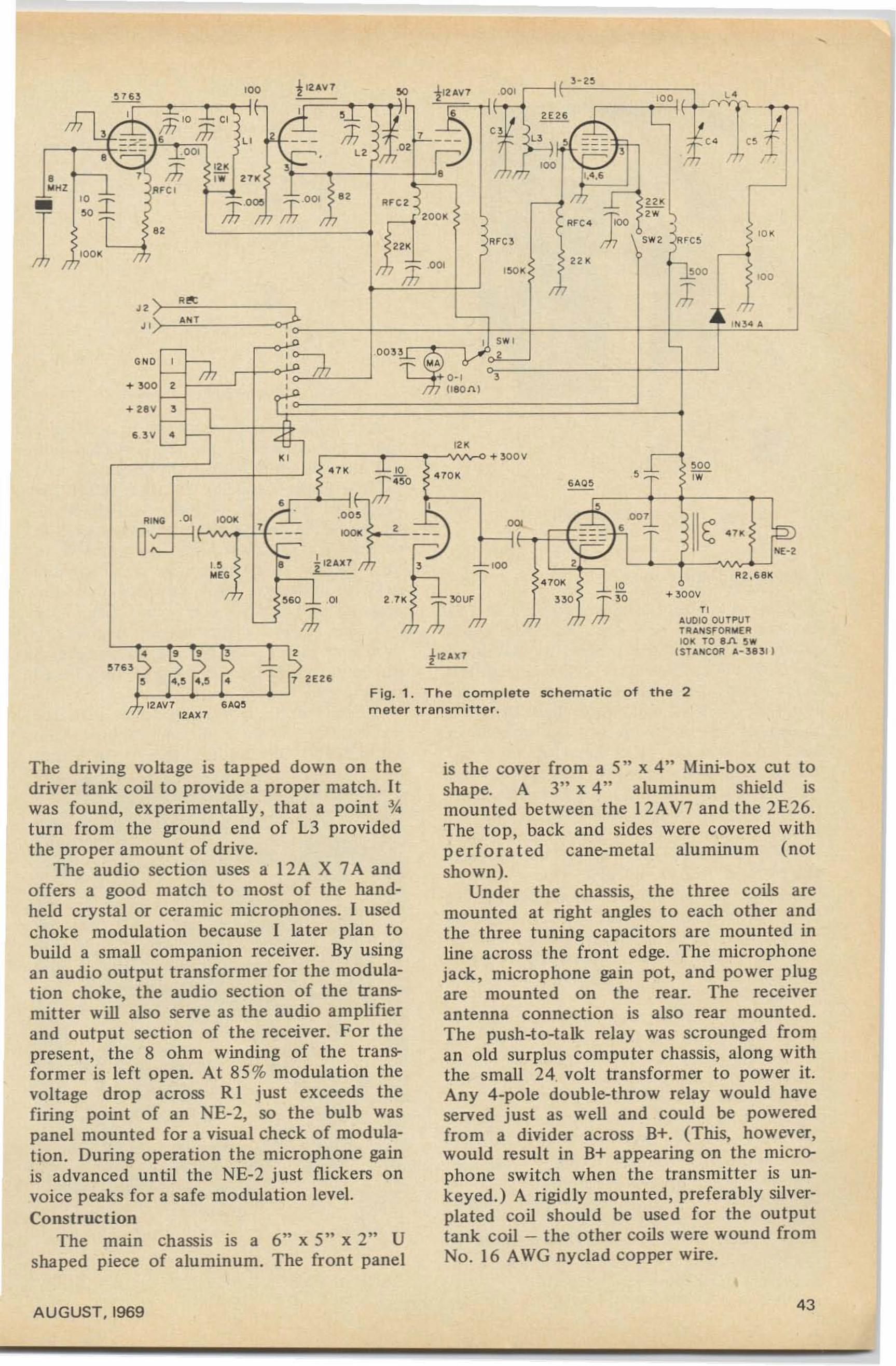
'0 '
-ce
~oo 1'00J; c
• IN 34 '"
11,4 ,6
3 - 2~
""26 /:::I~ L " I,
---fu ; ~"r.,
r-:+i m ,b '"
1,.
ArC4 100 •
$ W2 ~rc~
"'"
!'Ife3
'"
ArC2
'"I,r, :f .00'
D)~---+----=+-!--W~~~I ;::, I $ W I
, .0 0 03 '1'3 ..# ~ 2. N', n r. MA _, L-_..J + 0 - 1 3I It7 !180M
T,
'"
1
"
-d:-0 0 l
-r- '2 1<m ,•Ar c ,
s '"'
6 3V 4
+ 30 0 2
+ O2ev 3
/
1ii 10 :::!: CI
===' Iti•
10 01<'---±
•."•
NE-2
' 00,.
A2 ,681<
+ 30 0V
"AUDIO OUTPUTTRAN$rORt,lE R10 1< TO 8A ~w
I STA NCOR ,1, -38311
,-1
,
a
6AQ~-r:--t--t--~---,
schematic of the 2
47 01< 10
3~ J ~O'"
Fig. 1 . The completemeter transmitter,
~60 ~~ ,0 1
J;
---
t :2E26
'''''''
"."
AING _01
D~
/; 102AV712AX 7
The driving voltage is tapped down on thedriver tank coil to provide a proper match. Itwas found, experimentally, that a point %turn from the ground end of L3 providedthe proper amount of drive.
The audio section uses a 12A X 7A andoffers a good match to most of the handheld crystal or ceramic microphones. I usedchoke modulation because I later plan tobuild a small companion receiver. By usingan audio output transformer for the modulation choke, the audio section of the transmitter will also serve as the audio amplifierand output section of the receiver. For thepresent, the 8 ohm winding of the transformer is left open. At 85% modulation thevoltage drop across Rl just exceeds thefiring point of an NE-2, so the bulb waspanel mounted for a visual check of modulation. During operation the microphone gainis advanced until the NE-2 just flickers onvoice peaks for a safe modulation level.Construction
The main chassis is a 6" x 5" x 2" Ushaped piece of aluminum. The front panel
is the cover from a 5" x 4" Mini-box cut toshape. A 3" x 4" aluminum shield ismounted between the l2AV7 and the 2E26.The top, back and sides were covered withperforated cane-metal aluminum (notshown).
Under the chassis, the three coils aremounted at right angles to each other andthe three tuning capacitors are mounted inline across the front edge. The microphonejack, microphone gain pot, and power plugare mounted on the rear. The receiverantenna connection is also rear mounted.The push-to-talk relay was scrounged froman old surplus computer chassis, along withthe small 24. volt transformer to power it.Any 4-pole double-throw relay would haveserved just as well and could be poweredfrom a divider across B+. (This, however,would result in B+ appearing on the microphone switch when the transmitter is unkeyed.) A rigidly mounted, preferably silverplated coil should be used for the outputtank coil - the other coils were wound fromNo. 16 AWG nyclad copper wire.
AUGUST, 1969 43
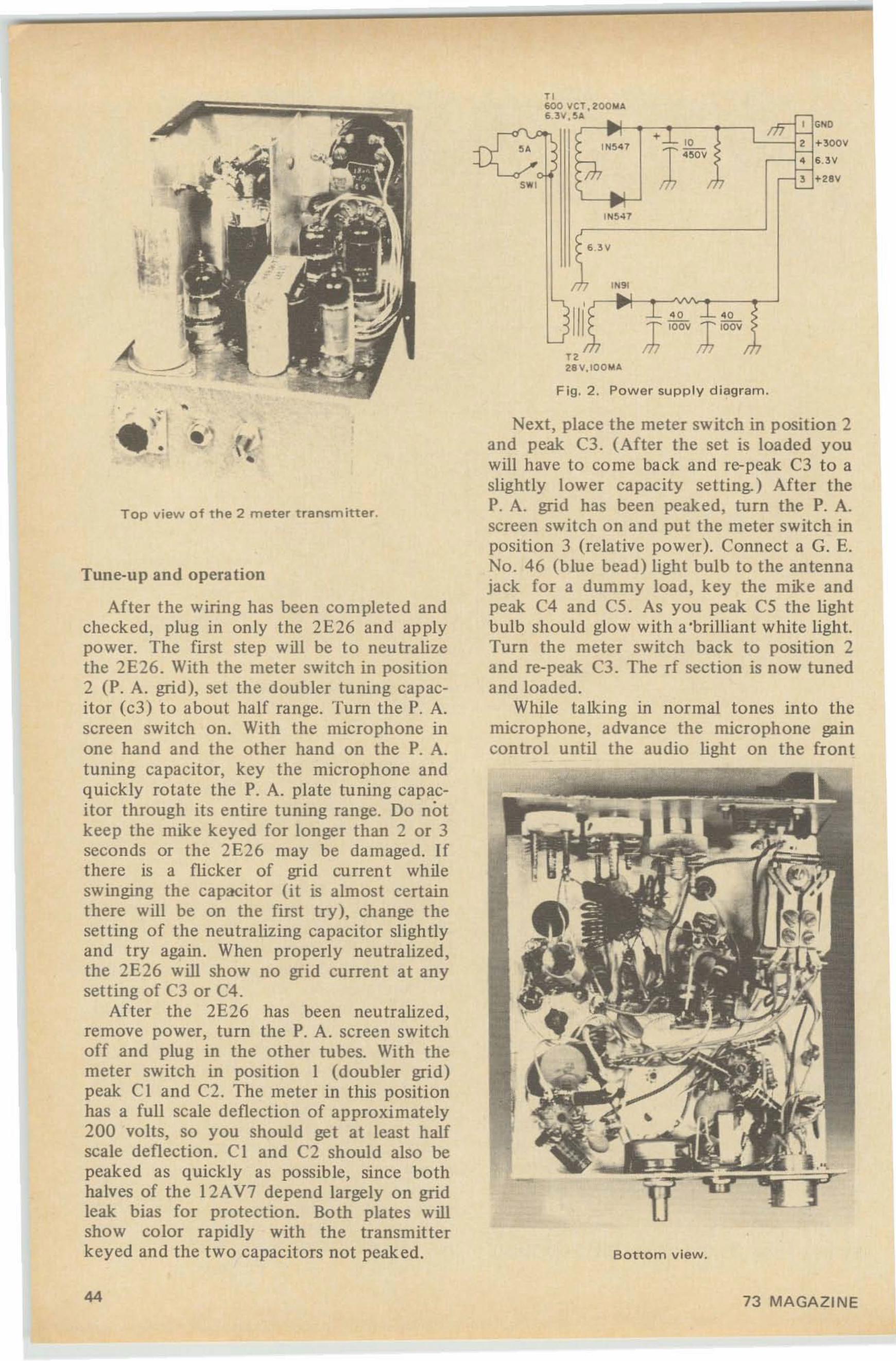
'0
1"°'
1... 9 1
1... 54 7
1"' 5 4 1
t a28 V. 100"'A
Fig . 2 . Power supply diagram .
r r600 vct , :rOOlolA63V,!i A
,.,
Next, place the meter switch in position 2and peak C3. (After the set is loaded youwill have to co me back and re-peak C3 to aslightly lower capacity setting. ) After theP. A. grid has been peaked, turn the P. A.screen switch on and put the meter switch inposition 3 (relative power). Connect a G. E.No . 46 (blue bead) light bulb to the antennajack for a dummy load, key the mike andpeak C4 and C5. As you peak C5 the lightbulb should glow with a 'brilliant white light.Turn the meter switch back to position 2and re-peak C3. The rf section is now tunedand loaded.
While talking in normal tones into themicrophone, advance the microphone gaincontrol until the audio light on the front
Bottom view.
Tune-up and operation
After the wiring has been completed andchecked, plug in only the 2E26 and applypower. The first step will be to neutralizethe 2E26. With the meter switch in position2 (P. A. grid), set the doubler tuning capacitor (c3) to about half range. Tum the P. A.screen switch on. With the microphone inone hand and the other hand on the P. A.tuning capacitor, key the microphone andquickly rotate the P. A. plate tuning capacitor through its entire tuning range. Do notkeep the mike keyed for longer than 2 or 3seconds or the 2E26 may be damaged. Ifthere is a rucker of grid curren t whileswinging the capacitor (it is almost certainthere will be on the first try) , change thesetting of the neutralizing capacitor slightlyand try again . When properly neutralized,the 2E26 will show no grid current at anysetting of C3 or C4 .
After the 2E26 has been neutralized,remove power, turn the P. A. screen switchoff and plug in the other tubes. With themeter switch in position I (doubler grid)peak C l and C2. The meter in this positionhas a full scale deflection of approximately200 volts, so you should get at least halfscale deflection. CI and C2 should also bepeaked as quickly as possible, since bothhalves of the 12AV7 depend largely on gridleak bias for protection. Both plates willshow color rapidly with the transmitterkeyed and the two capacitors not peaked.
Top view of the 2 meter transmitter.
44 73 MAGAZINE
Model 407534.95
ppd .
• Dependable operation• Rugged Eimac 3 ·1 OOOZ• Insfanf Transmit. ALe• Fast Band Swifching• Easy Load and Tune• Real Signal Impact
BTl LK-2000 , , , Fo'maximum legal amateurhlput • , • SSB, cw, RTTY.Price •. .. $79500
BTl LK-2000HD .' ,for heavy dufy applica.fions such as MARS, highpower RTTY and SSB.Price ... • $89500
'.
THE BEST
2 METERCONVERTER
,- -
\ .•
>
~
~; .~ ,-,
.---~ (
••
\
Dept . H, 196·23 Jamaica Ave ., Hollis, N.Y. 11423
VANGUARD LABS
144·146 MHz in . 28·30 MHz outor 146--148 MHz with a seeeee crystal
Availab le a t $ 3 .9 5 eac h .A f ull description of this fantastic converterwould fill t h is page, hut you can take our wordfor it ror those o f h undreds o f s a t is fi ed users )that it'll t he best. The reason is s im ple--we uset hr-ee H CA du nl gate MO ::lt' ET s, on e b ipol a r, a nd:~ diodes in the best circuit eve r-. Still not con vinced ? Then se n d fo r our free cata loz and eetthe f u ll desc ription, plus photos and even t hesch ema tic.Can 't wait '? Then sen d us a p ostal m oney o r de rfor S3·1.!)5 a nd we'll r ush the 40i ou t to you.NOT E: T h e Monel 40i is also available in an yf!"el1u ency com bin ation up to 450 ::"oIH T. (som e a th tgher pi-ices ] as Iiat ed in ou r cat.aloe.
·Ne.... York C ity and Stdte residents ddd local sdles tex.
.T' AMAnUR DIVISION
Halstrom Technical Products4616 Santa Fe, San Diego, Ca. 92109
'"
,e-0.'
s ---J- ,
"'"+ 01 _ ,.
1" " ,,.v1. 1 ,.
Parts dataRfcl - I mHRfc 2 - Ohmite 2-50.Rfc3 - Ohmite 2-144 .Rfc4 - Ohmite 2-144.Rfc5 - 22 turns No. 24 CW on 11." d.Ll - II " turns No. 16, W' d. (B&WjL2 - 5 turns No. 16, W' d. 7/8" long.L3 - 3 turns No. 16 , l'" d. ,," I. ta pped ';';"from ground end.L4 - 4 turns No. 16, tapped I turn from ant.end.CI - APC50 with all but 8 plates removed.C3,4 - APC25 with all but 4 plates removed.C5 - APC50.
A Simple CW VOX forCathode Keyed Transmitters
After sendi ng in my application for NavyMARS, I was left with a juicy problem . SinceI didn't have any SSB gear, I was stuc k onCWo That meant I had to modify a little CWrig for full break-in traffic handling.
After trying everything in the book, alongwith some things which aren' t in the book,I came up with the following circuit.
This little job can transfer your antennaeither at fast keying speeds for traffic handling, or you can set the delay for those longrag-chews with the Novice down the bloc k.DI isolates the VOX from the transmitterkeying circuit . RI determines delay time.
... W4 UOY
,.I(( Y( OCATHOOES
panel just flickers on voice peaks. Thedumm y bulb should show an appreciableincrease in brilliance when you talk into themicrophone. To load into an anten na,simply peak C4 and C5 with the meterswitch in position 3.
There is a setting of R1 which keeps therelay closed. If you don't like to fool withcritical settings of R I , add a resistor toground.
Because of differences in key voltage andrelay characteristics, you may have to changethe value of CI to get the delay which suitsyou best. And, you won 't even have to sendBK. ..That first dot is always on time!
Elmo M. Moist , Jr. , K8QKT
AUGUST, 1969 45
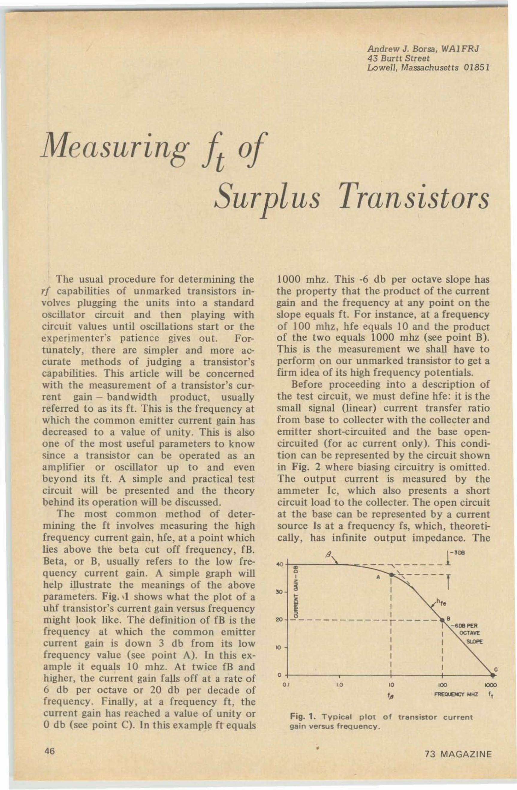
Andrew J. Borsa, WAIFRJ43 Burtt StreetLowell, Massachusetts 01851
oMeasuring tSurplus Transistors
1000 mhz. This -6 db per octave slope hasthe property that the product of the currentgain and the frequency at any point on theslope equals ft. For instance, at a frequencyof 100 mhz, hfe equals 10 and the productof the two equals 1000 mhz (see point B).This is the measurement we shall have toperform on our unmarked transistor to get afilm idea of its high frequency potentials.
Before proceeding into a description ofthe test circuit, we must define hfe: it is thesmall signal (linear) current transfer ratiofrom base to collecter with the collecter andemitter short-circuited and the base opencircuited (for ac current only). This condition can be represented by the circuit shownin Fig. 2 where biasing circuitry is omitted.The output current is measured by theammeter Ic, which also presents a shortcircuit load to the collecter. The open circuitat the base can be represented by a currentsource Is at a frequency fs, which, theoretically, has infinite output impedance. The
Fig. 1. Typical plot of transistor currentgain versus frequency .
c
rc
f,'.00.'
so
The usual procedure for determining therf capabilities of unmarked transistors involves plugging the units into a standardoscillator circuit and then playing withcircuit values until oscillations start or theexperimenter's patience gives out. Fortunately , there are simpler and more accurate methods of judging a transistor'scapabilities. This article will be concernedwith the measurement of a transistor's current gain - bandwidth product, usuallyreferred to as its ft. This is the frequency atwhich the common emitter current gain hasdecreased to a value of unity. This is alsoone of the most useful parameters to knowsince a transistor can be operated as anamplifier or oscillator up to and evenbeyond its ft. A simple and practical testcircuit will be presented and the theorybehind its operation will be discussed.
The most common method of determining the ft involves measuring the highfrequency current gain, hfe, at a point whichlies above the beta cut off frequency, fB.Beta, or B, usually refers to the low frequency current gain. A simple graph willhelp illustrate the meanings of the aboveparameters. Fig. •l shows what the plot of auhf transistor's current gain versus frequencymight look like. The definition of fB is thefrequency at which the common emittercurrent gain is down 3 db from its lowfrequency value (see point A). In this example it equals 10 mhz. At twice fB andhigher, the current gain falls off at a rate of6 db per octave or 20 db per decade offrequency. Finally, at a frequency ft, thecurrent gain has reached a value of unity oro db (see point C). In this example ft equals
46 • 73 MAGAZINE
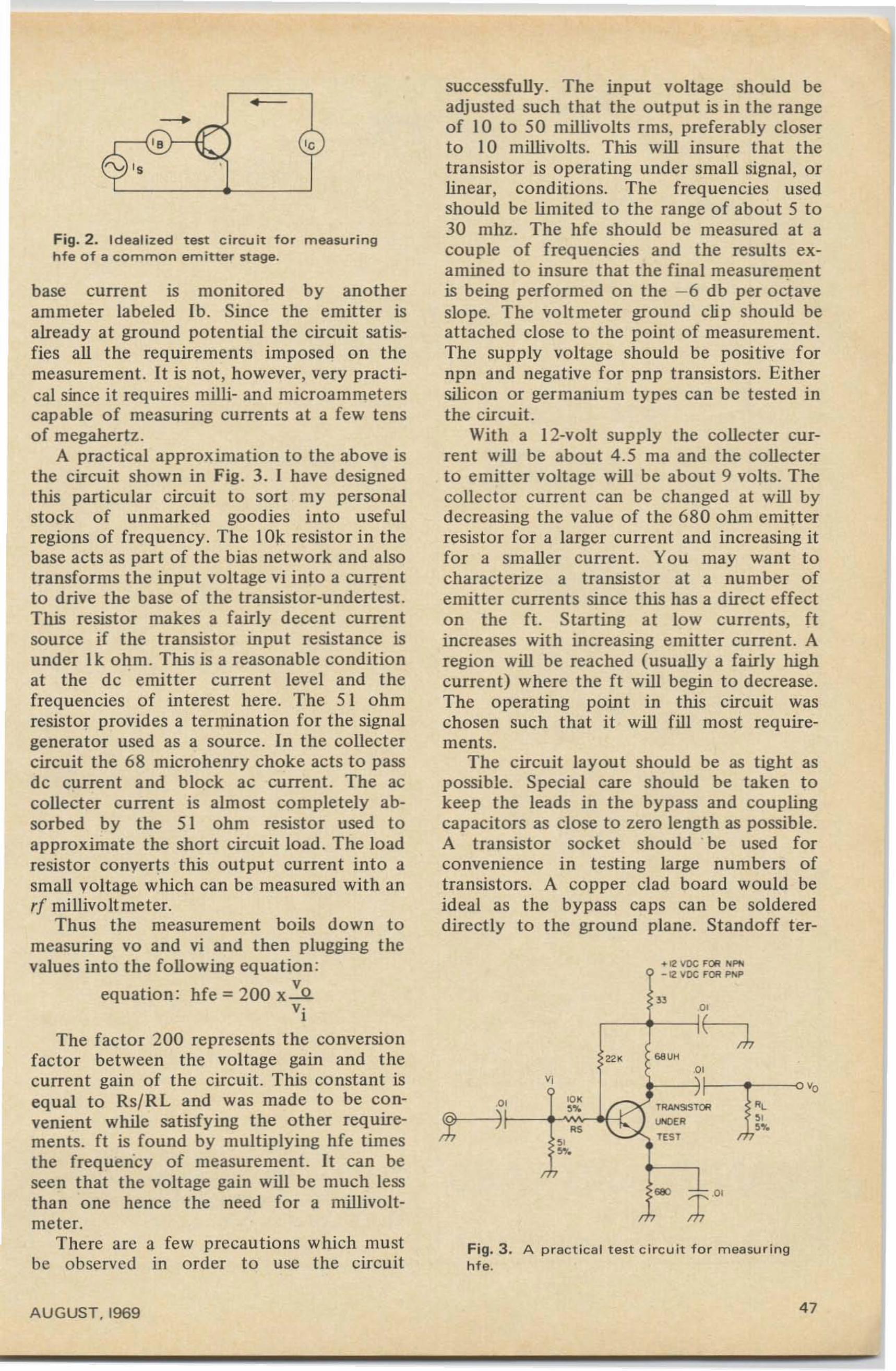
Fig. 3. A practi cal test circuit for measuringnte.
successfully. The input voltage should beadjusted such that the output is in the rangeof 10 to 50 millivolts rms, preferably closerto 10 millivolts. This will insure that thetransistor is operating under small signal, orlinear, conditions. The frequencies usedshould be limited to the range of about 5 to30 mhz. The hfe should be measured at acouple of frequencies and the results examined to insure that the final measurementis being performed on the - 6 db per octaveslope. The voltmeter ground clip sho uld beattached close to the point of measurement.The supply voltage should be positive fornpn and negative for pnp transistors. Eithersilicon or germanium types can be tested inthe circuit.
With a 12-volt supply the collecter current will be about 4.5 rna and the collecterto emitter voltage will be about 9 volts. Thecollector current can be changed at will bydecreasing the value of the 680 ohm emitterresistor for a larger current and increasing itfor a smaller current. You may want tocharacterize a transistor at a number ofemitter currents since this has a direct effecton the ft . Starting at low currents, ftincreases with increasing emitter current. Aregion will be reached (usually a fairly highcurrent) where the ft will begin to decrease.The operating point in this circuit waschosen such that it will fill most requirements.
The circuit layout should be as tight aspossible. Special care should be taken tokeep the leads in the bypass and couplingcapacitors as close to zero length as possible.A transistor so cket should ' be used forconvenience in testing large numbers oftransistors. A copper clad board would beideal as the bypass caps can be soldereddirectly to the ground plane. Standoff ter-
'0
- 12 VDC FOR p",p
" I~IIE-:J,ee « ""
' i '~ ~
: '" " ",%C<
HIANSISTOR
""". ", es r.,%
"TEST....
r.sec ;rOO
r.
o
r
'e•
•
base current is monitored by anotherammeter labeled lb. Since the emitter isalready at ground potential the circuit satisfies all the requirements imposed on themeasurement. It is not, however, very practical since it requires milli- and microammeterscapable of measuring currents at a few tensof megahertz.
A practical approximation to the above isthe circuit shown in Fig. 3. ] have designedthis particular circuit to sort my personalstock of unmarked goodies into usefulregions of frequency . The 10k resistor in thebase acts as part of the bias network and alsotransforms the input voltage vi into a currentto drive the base of the transistor-undertest.This resistor makes a fairly decent currentsource if the transistor input resistance isunder 1k ohm . This is a reasonable conditionat the de emitter current level and thefrequencies of interest here. The 51 ohmresistor provides a termination for the signalgenerator used as a source. In the collectercircuit the 68 microhenry choke acts to passdc current and block ac current. The accollecter current is almost completely absorbed by the 51 ohm resistor used toapproximate the short circuit load. The loadresistor converts this output current into asmall voltage which can be measured with anrf millivoltmeter.
Thus the measurement boils down tomeasuring vo and vi and then plugging thevalues into the following equation:
equation: hfe = 200 x~v·I
The factor 200 represents the conversionfactor between the voltage gain and thecurrent gain of the circuit . This constant isequal to RsjRL and was made to be convenient while satisfying the other requirements. ft is found by multiplying hfe timesthe frequency of measurement. It can beseen that the voltage gain will be much lessthan one hence the need for a millivoltmeter.
There are a few precautions which mustbe observed in order to use the circuit
Fig. 2. Idealized test circuit for measuringhfe of a c omm o n em itter stage.
AU GUST. 1969 47
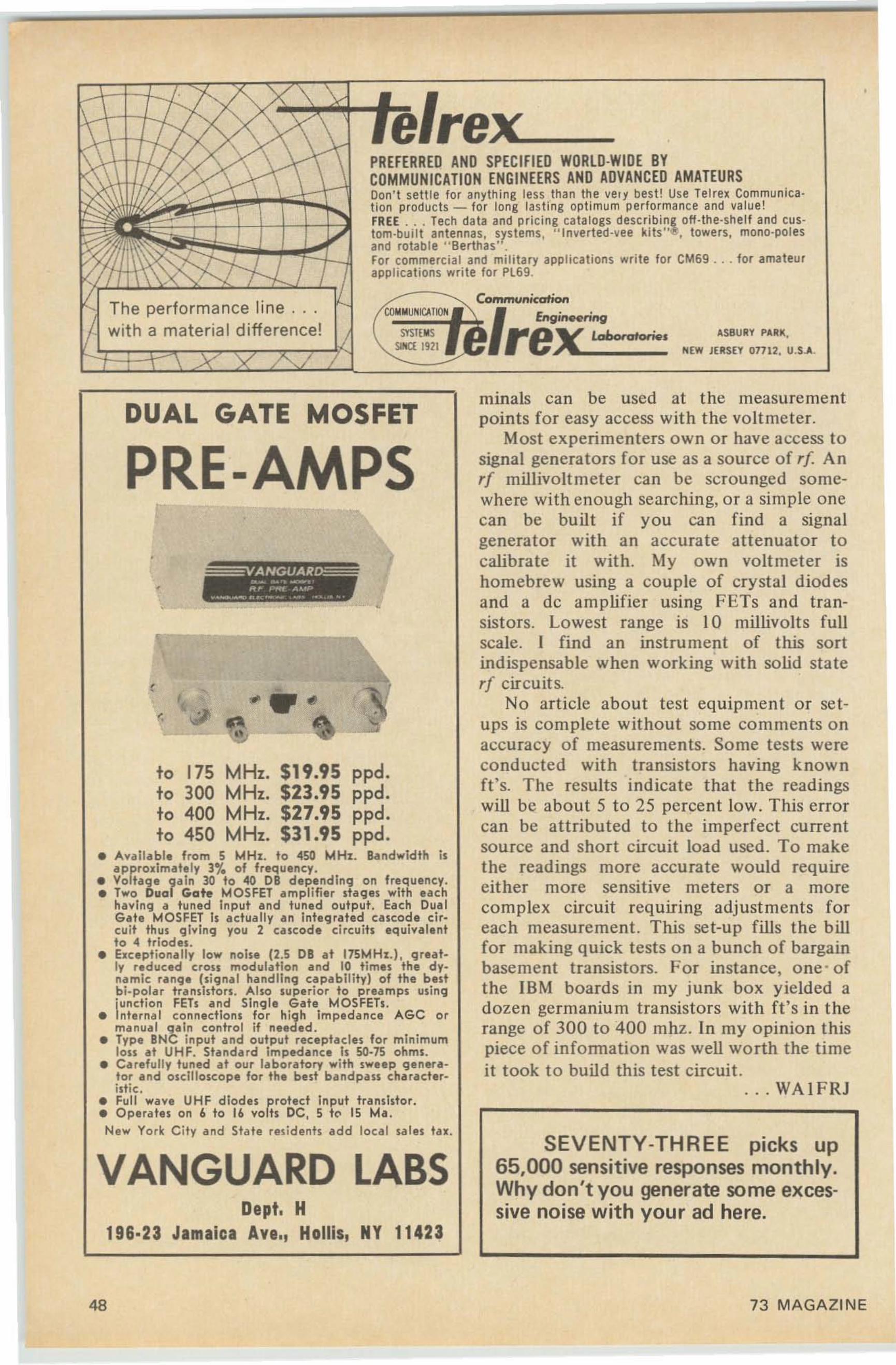
ASBURY PARk.
NEW JERSEY 01712. U.S.A.
SYSTE MSSIHC( 1921
e/rex_PREFERRED AND SPECIfIED WDRLD·WIDE BYCDMMUNICATlDN ENGINEERS AND ADVANCED AMATEURSDon't settle for anything less than the vert best! Use rerrex Communicat ion products - for long lasting opt imum perfo rma nce and value!FREE ... Tech data and pricing catalogs describing ou -tne-snet t and custom-built antennas , systems, " Inverted-vee k its"~ , towers, mono-polesand rotaere " Berthas".For commercia l and mi litary applicat ions wr ite for CM69 ... for amateurapplications write for Pl69.
,
The performance li ne . .with a material difference!
DUAL GATE MOSFET
SEVENTY-THREE picks up65,000 sensitive responses monthly.Why don't you generate some excessive noise with your ad here.
minals can be used at the measurementpoints for easy access with the voltmeter.
Most experimenters own or have access tosignal generators for use as a source of rf Anrf millivolt meter can be scrounged somewhere with enough searching, or a simple onecan be built if you can find a signalgenerator with an accurate attenuator tocalibrate it with. My own voltmeter ishomebrew using a couple of crysta l di odesand a de amplifie r using FETs and transistors. Lowest ra nge is 10 millivolts fullscale. I find an instrument of this sortindispensable when working with solid staterf circuits.
No article about test equipment or setups is complete without so me co mments onaccuracy of measurements. Some tests wereconducted with transis tors having knownIt 's. The results indicate that the readingswill be about S to 2S percent low. This errorcan be att ributed to the imperfect curre ntsource and short circuit load used. To makethe readings more accura te would requireeither more sensitive meters or a morecomplex circuit requiring adjustments foreach measure ment. This set-up fills the billfor making quick tests o n a bunch of bargainbasement transistors. For instance, one ' oft he IBM boards in my junk box yielded adozen germanium transistors with ft' s in therange of 300 to 400 mhz. In my opinion thispiece of information was well wo rth the timeit took to build this test circuit.
. . . WAI FRJ
•
.. ...A•
•
,
to 175 MHz. $19.95 ppd.to 300 MHz. $23.95 ppd.to 400 MHz. $27.95 ppd.to 450 MHz. $31.95 ppd.
• Available from 5 MHz. to 450 MHz. Ba ndwid th isapproximately l,.. of frequency.
• Volt"ge gain 30 to 40 DB d epend ing on freq uency.• Two Dual Gate MOSFET a mplifier sta ges with each
having a tuned Input a nd tu ned out put . Ea ch DualGa te MO SFET Is actua lly a n integ rated cascode ci rcuit thus giving you 2 eeseede circuih eq uivalentto 4 triodes .
• Exceptionally low noise (2.5 DB at 17SMHx.), greatly red uced crou modulation and 10 times the dynamic range (signal handling capability) of the bestbi-polar tunsidon. Also superior to pream ps using',uncti on FEls e nd Single Gate MOSFETs.
• nte met connections fo r high Impeda nce AG C ormanual qaln control if needed .
• Type BNC input and output receptacles for minimumlou at UHF. Standard impedance Is 50-7) ohm s.
• Carefully tuned at our laboratory with sweep generator and oscilloscope for the but bandpass characteristic.
• Full wave UHF diodes pr ot eel inp ut transistor.• Operates on 6 to 16 volh DC, 5 tC' 15 Mol .New York City and State residents add local sales tax.
VANGUARD LABS
•
Dept. H196·23 Jamaica Ave., Hollis, NY 11423
•
PRE-AMPS
48 73 MAGAZINE
Skylines or 160,
Jim Ashe, WIEZT
Made Simpler
About a year ago the value of 160 metersas a ham band was much less than now. Theregulations were too confining. New regulations, although complex, offer much moreopportunity for local ragchewing, and someadventurous amateurs may be working transoceanic DX even as you sit reading this .
Your on-the-air competition on 160 willbe far less than on 80, the propagation muchsteadier than on 20. Effective ranges aretypically several tens or a few hundreds ofmiles. And at 160's low frequencies you canget by with inexpensive surplus transistors totryout those transmitter ideas. 160 is worthsome of your time and money now.
There's a bit of history on 160, too. It ison the dividing line between two very different kinds of radio. Now it's at the bottomof the amateur spectrum, but there is a timein some men's memories when it was at thetop. Communications engineers once believed you used long waves for long rangecommunications, since nobody understoodhow short waves could get over the horizon.
The general thinking then was that thehigh frequencies had a low practical utility,and the amateurs wound up with a hugechunk of radio spectrum nobody else wanted. Many interesting records date from thattime for the hams soon discovered the realpotentialities of short-wave propagation.
Now we understand the differences between ground-wave and sky-wave propagation . We know why the ionosphere is responsible for sky-wave propagation, since itseffects cannot be ignored by anybody andare very important for the DX that interestsmany amateurs. And we have a band wherethe special advantages of ground-wave propagation can be applied and enjoyed .
Ground-wave is made to order for localrag-chewing. Saving the higher-frequencybands for DX, we can easily build simple antennas optimized for 160 meter verticallypolarized radiation . In a way this is making
AUGUST, 1969
a virtue of necessity, but we can come backto that point later. First we should discussthe FCC's complex frequency and powerassignments, and review some facts about160 meter propagation.Eight Pieces of Pie
When you tune your receiver across 1.8to 2.0 MHz you will hear a variety of sharpregular beats, quite evidently for some purpose other than communication. Thesesounds first appeared on 160 during WW2,when a tremendous need was developing forsome fast, reliable, and accurate method ofnavigation. Ship and airplane navigators observe the beats in pairs on an oscilloscopelike indicator. Then, using the resulting timemeasurements and special navigation tables,they quickly locate their vessels with an accuracy of a thousand feet or so. This servicewas very useful during the war, and has hada great commercial value since.
The system is called " loran," coined from"long-range navigation ." Various engineering necessities planked this service into theamateur 160 meter band, where it has stayedto the annoyance of many hams. With theloran usage receiving first priority and thehams reduced to low powers in the face ofkilowatt pulse interference , 160 meters hasbecome a less-than-popular band for amateurcommunications.
But navigation technology has been developing, and with the advent of new navigational space satellites, UHF beacon systems, inertial navigation, and computerization (which saves time and improves accuracy) the loran services have lost importanceover the past ten or twenty years. Recentlythe FCC has raised and reallocated its 160meter power limits. This easing togetherwith the development of amateur technology has made the band interesting again.
Yet the 160 meter band is still a sharedservice, and the FCC has written a remark-
49
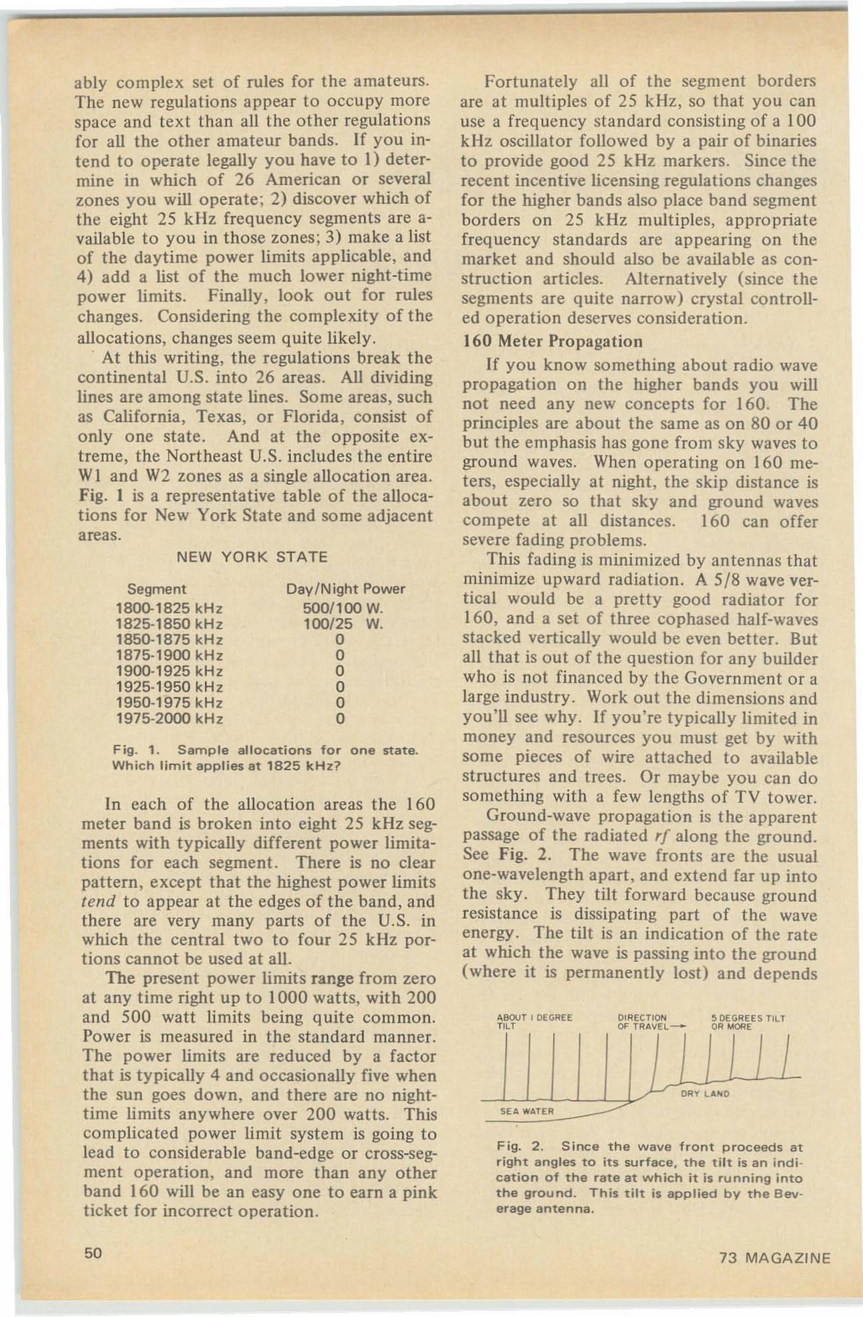
I
NEW YORK STATE
Fig. 1. Sample allocations for one state.Which limit applies at 1825 kHz?
In each of the allocation areas the 160meter band is broken into eight 25 kHz segments with typically different power limitations for each segment. There is no clearpattern, except that the highest power limitstend to appear at the edges of the band, andthere are very many parts of the U.S. inwhich the central two to four 25 kHz portions cannot be used at all.
The present power limits range from zeroat any time right up to 1000 watts, with 200and 500 watt limits being quite common.Power is measured in the standard manner.The power limits are reduced by a factorthat is typically 4 and occasionally five whenthe sun goes down, and there are no nighttime limits anywhere over 200 watts. Thiscomplicated power limit system is going tolead to considerable band-edge or cross-segment operation, and more than any otherband 160 will be an easy one to earn a pinkticket for incorrect operation.
ably complex set of rules for the amateurs.The new regulations appear to occupy morespace and text than all the other regulationsfor all the other amateur bands. If you intend to operate legally you have to 1) determine in which of 26 American or severalzones you will operate; 2) discover which ofthe eight 25 kllz frequency segments are available to you in those zones; 3) make a listof the daytime power limits applicable, and4) add a list of the much lower night-timepower limits. Finally, look out for ruleschanges. Considering the complexity of theallocations, changes seem quite likely.
. At this writing, the regulations break thecontinental U.S. into 26 areas. All dividinglines are among state lines. Some areas, suchas California, Texas, or Florida, consist ofonly one state. And at the opposite extreme, the Northeast U.S. includes the entireWI and W2 zones as a single allocation area.Fig. 1 is a representative table of the allocations for New York State and some adjacentareas.
DIRECTION e DEGREES TILTOF TRAY EL--' OR MORE
A.BOIJT I DEGREETILT
DRY L"''''O
SE A WATER
•
Fortunately all of the segment bordersare at multiples of 25 k Hz, so that you canuse a frequency standard consisting of a 100kHz oscillator followed by a pair of binariesto provide good 25 kHz markers. Since therecent incentive licensing regulations changesfor the higher bands also place band segmentborders on 25 kHz multiples, appropriatefrequency standards are appearing on themarket and should also be available as construction articles. Alternatively (since thesegments are quite narrow) crystal co ntrolled operation deserves consideration.160 Meter Propagation
If you know something about radio wavepropagation on the higher bands you willnot need any new concepts for 160. Theprinciples are about the same as on 80 or 40but the emphasis has gone from sky waves toground waves. When operating on 160 meters, especially at night, the skip distance isabout zero so that sky and ground wavescompete at all distances. 160 can offersevere fading problems.
This fading is minimized by antennas thatminimize upward radiation. A 5/8 wave vertical would be a pretty good radiator for160, and a set of three cophased half-wavesstacked vertically would be even better. Butall that is out of the question for any builderwho is not financed by the Government or alarge industry. Work out the dimensions andyou'll see why. If you're typically limited inmoney and resources you must get by withsome pieces of wire attached to availablestructures and trees. Or maybe you can dosomething with a few lengths of TV tower.
Ground-wave propagation is the apparentpassage of the radiated ,r along the ground.See Fig. 2. The wave fronts are the usualone-wavelength apart, and extend far up intothe sky. They tilt forward because groundresistance is dissipating part of the waveenergy . The tilt is an indication of the rateat which the wave is passing into the ground(where it is permanently lost) and depends
Fig. 2 . Since the wave front proceeds atright angles to its surface. the tilt is an indi cation of the rate at which it is running intothe ground. This tilt is applied by the Beverage antenna .
Day/Night PowerSOO/l00 W.100/25 W.
oooooo
Segment180().1825 kHz1825·1850 kHz1850·1875 kHz1875·1900 kHz1900·1925 kHz1925·1950 kHz1950·1975 kHz1975·2000 kHz
50 73 MAGAZINE
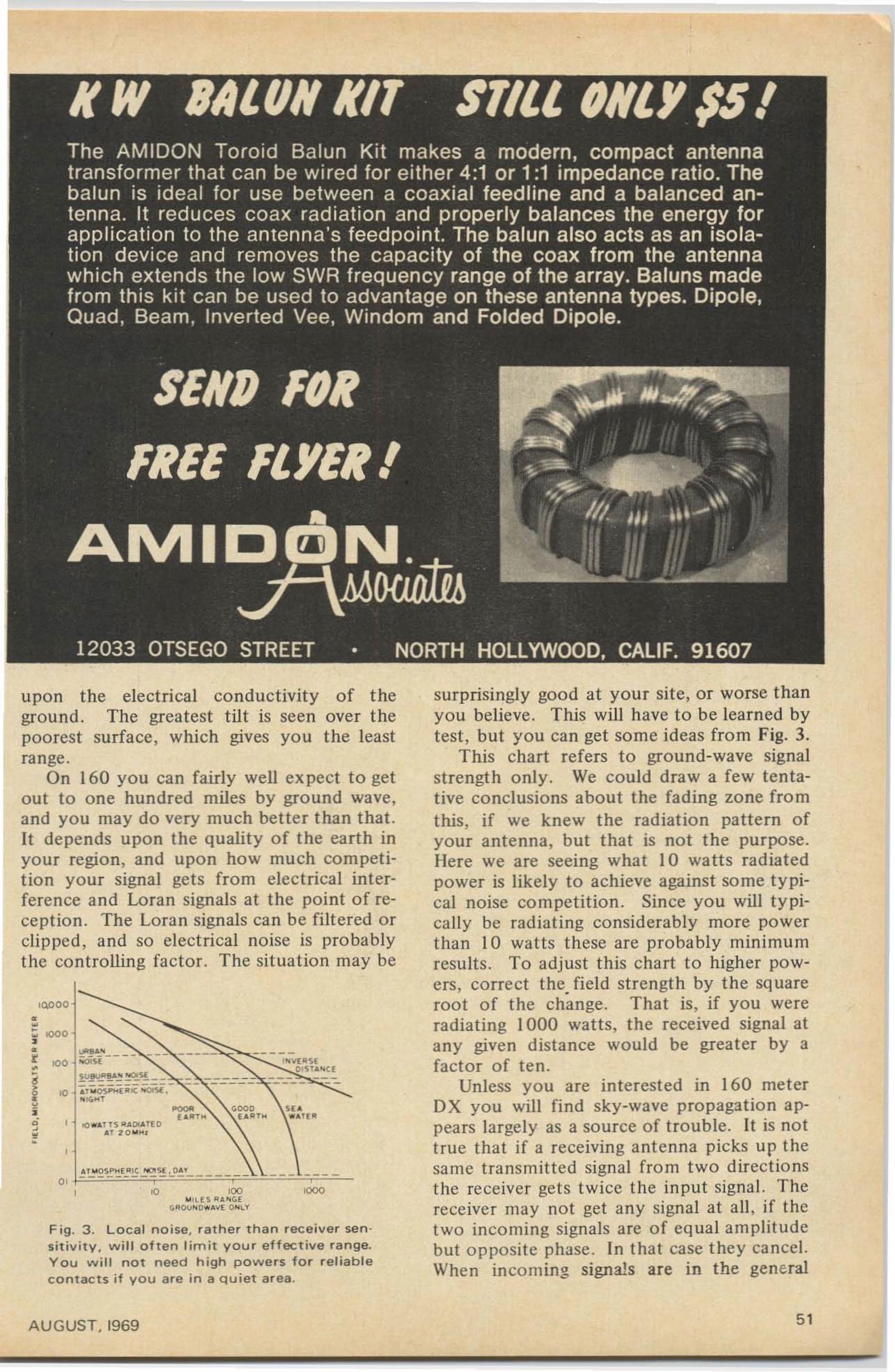
upon the electrical conductivity of theground . The greatest tilt is seen over thepoorest surface, which gives you the leastrange .
On 160 you can fairly well expect to getout to one hundred miles by ground wave,and you may do very much better than that.It depends upon the quality of the earth inyour region, and upon how much competition your signal gets from electrical interference and Loran signals at the point of reception . The Loran signals can be filtered orclipped, and so electrical noise is probablythe controlling factor. The situation may be
,!"io",•
oo ...rn ~A Do"'H OAT t o .....
'0 100 '000"" f ~ R . ~ ~ E
~"O""D"'AY~ O" 'Y
Fig . 3 . Local noise, rather than receiver sen siti vity . will often limit your effective range.You will not need high powers for reliablec o n t ac t s if y ou are in a quiet area .
surprisingly good at your site, or worse thanyou believe. This will have to be learned bytest, but you C3n get some ideas from Fig. 3.
This chart refers to ground-wave signalstrength only. We could draw a few tentative conclusions about the fading zone fromthis, if we knew the radiation pattern ofyour antenna, but that is not the purpose.Here we are seeing what J0 watts radiatedpower is likely to achieve against some typical noise competition . Since you will typically be radiating considerably more powerthan 10 watts these are probably minimumresults. To adjust this chart to higher powers, correct thefield strength by the squareroot of the change. That is, if you wereradiating 1000 watts, the received signal atany given distance would be greater by afactor of ten.
Unless you are interested in 160 meterDX you will find sky-wave propagation appears largely as a source of trouble. It is nottrue that if a receiving antenna picks up thesame transmitted signal from two directionsthe receiver gets twice the input signal. Thereceiver may not get any signal at all, if thetwo incoming signals are of equal amplitudebut opposite phase. In that case they cancel.When incoming signals are in the general
AUGUST. 1969 51
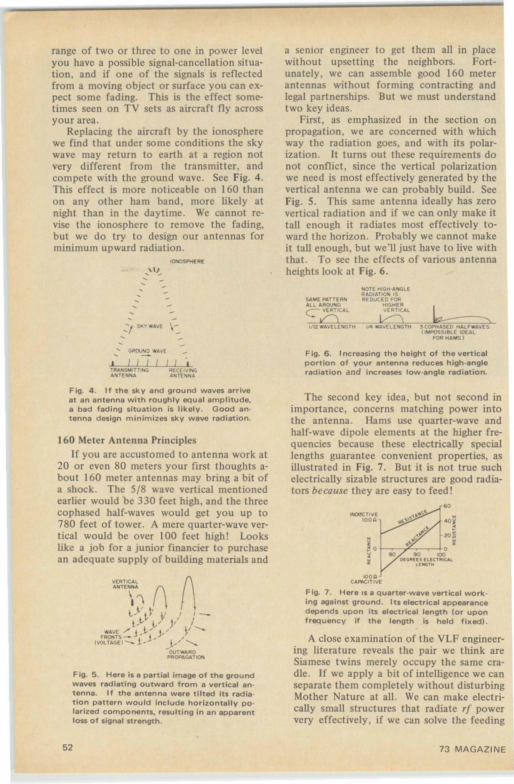
range of two or three to one in power levelyou have a possible signal-cancellation situation , and if one of the signals is reflectedfrom a moving object or surface you can expect some fading. This is the effect sometimes seen on TV sets as aircraft fly acrossyour area.
Replacing the aircraft by the ionospherewe find that under some conditions the skywave may return to earth at a region notvery different from the transmitter, andcompete with the ground wave. See Fig. 4.This effect is more noticeable on 160 thanon any other ham band, more likely atnight than in the daytime. We cannot revise the ionosphere to remove the fading,but we do try to design our antennas forminimum upward radiation .
100000SP!olERE
'", -, -
a semor engineer to get them all in placewithout upsetting the neighbors. Fortunately, we can assemble good 160 meterantennas without forming contracting andlegal partnerships. But we must understandtwo key ideas.
First, as emphasized in the section onpropagation, we are concerned with whichway the radiation goes, and with its polarization. It turns out these requirements donot conflict, since the vertical polarizationwe need is most effectively generated by thevertical antenna we can probably build. SeeFig. 5. This same antenna ideally has zerovertical radiation and if we can only make ittall enough it radiates most effectively toward the horizon . Probably we cannot makeit tall enough, but we'll just have to live withthat. To see the effects of various antennaheights look at Fig. 6.
------' / 5>( v "". \1: \-
, ---
S.~E PATTERNAl l AROUNDC VER TICAL
.Q1112 WA\1: LENGTH
.."3 COPH4SE D HAlF.....4VE SCI~POSSjBlE IDEAL
FOR HAMS )
... GROUND ......VE, - - Fig. 6 . Increasing the height of the vertical
portion of your antenna reduces high-angleradiation and increases low-angle radiation.
loonc . P4ClnvE
Fig. 7. Here IS a quarter-wave vertical work ing against ground. Its electrical appearancedepends upon its electrical length (or uponfrequency if the length is held fixed) .
A close examination of the VLF engineering literature reveals the pair we think areSiamese twins merely occupy the same cradle . If we apply a bit of intelligence we canseparate them completely without disturbingMother Nature at all. We can make electrically small structures that radiate rf powervery effectively, if we can solve the feeding
The second key idea, but not second inimportance, concerns matching power intothe antenna. Hams use quarter-wave andhalf-wave dipole elements at the higher frequencies because these electrically speciallengths guarantee convenient properties, asillustrated in Fig. 7. But it is not true suchelectrically sizable structures are good radiators because they are easy to feed!
•40~,2O:i
••
. 0woecnve
loon
Fig. 5 . Here is a partial image of the groundwaves radiating outward from a vertical antenna. If the antenna were tilted its redte tion pattern would include horizontally polarized components. resulting in an apparenttess of signal strength.
160 Meter Antenna PrinciplesIf you are accustomed to antenna work at
20 or even 80 meters your first thoughts about 160 meter antennas may bring a bit ofa shock. The 5/8 wave vertical mentionedearlier would be 330 feet high, and the threecophased half-waves would get you up to780 feet of tower. A mere quarter-wave vertical would be over 100 feet high! Lookslike a job for a junior financier to purchasean adequate supply of building materials and
~~~~\\ (\ 0\l ..V ~~' V / : -t ~t... V JI I
""'.VE /' J_t. ,.- J/ V---FRONTS _ ! J . ,
(VOl U GE) __ - )./ '<,OUT""'. RD
PROP.GATIQN
Fig. 4. If the sky and ground waves arriveat an antenna with roughly equal amplitude,a bad fading situation is likely. Good antenna design minimizes sky wave radiation.
52 73 MAGAZINE
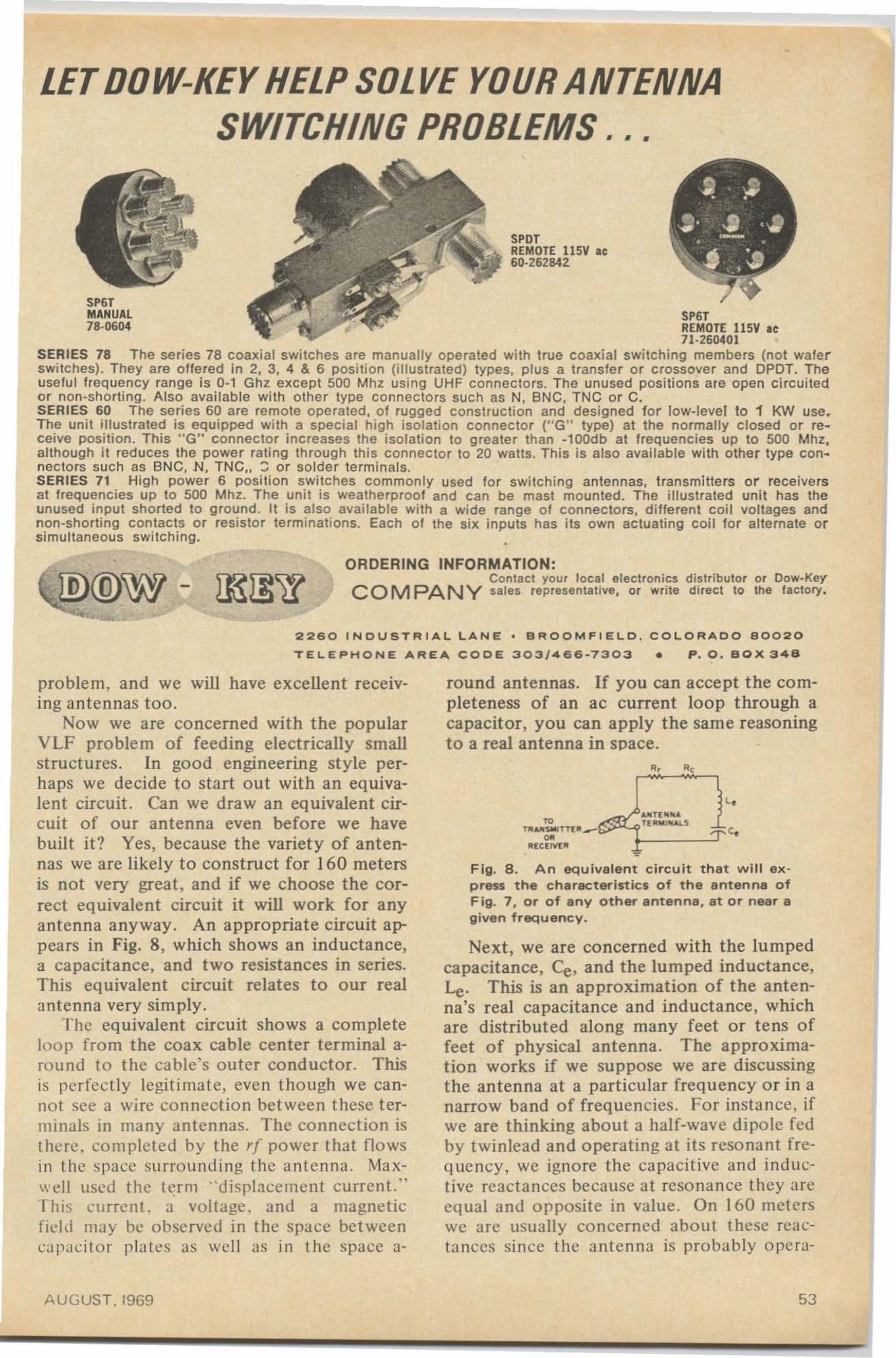
LETDOW-KEY HELP SOLVE YOUR ANTENNASWITCHING PROBLEMS . . .
SPOTREMOTE 115V at60·262842
•
5P6TMANUAL78-0604
5P6TREMOTE llSV ee71·260401
SERIES 78 The se ries 78 coaxial switches are manually operated with true coaxial switching members (not wafe rswitches). They are offered in 2, 3. 4 & 6 position (i llustrated) types, plus a transfer or crossover and CPOT. Theuseful frequency range is 0-1 Ghz except 500 Mhz using UHF connecto rs. The unused posi tions are open ci rcuitedor non-shorting. Also avai lab le with other type connecto rs such as N, BNG, TNC o r C.SERIES 60 The series 60 are rem ote operated. o f rugged const ruc tion and designed for low-level to 1 KW usa.The unit i llustrated is equipped with a special high isolation connec to r ("G" type) at the normally closed or receive position . This " G" connector increases the isolati on to greater than ·100db at frequencies up to 500 Mhz,although it reduces the power rating through thi s Connec to r to 20 watts. Th is is also available with other type connectors such as BNC, N , TNC" ::; or solder terminals .SERIES 71 High power 6 position switches common ly used for switching antennas. transmi tters o r receive rsat frequencies up to 500 Mhz. The unit is weatherproof and can be mast mounted. The illustrated unit has theunused input shorted to ground. It is also available with a wide range of connectors, d ifferent coil voltages andnon-shorttnq contacts or resistor term inations. Each of the six inputs has its own actuating coil for alternate orsimultaneous swi tching.
-ORDERING INFORMATION:
Contact your local electron ics distributor or Dow-KeyCOM PANY sales representative. or write direct to the factory.
2260 I ND U S T R I AL LAN E · B RO O M F I E L D , COLORADO 8 0 020
TEL EP H O NE AREA CODE 303/466-7303 • P . O. BO X 348
F ig. 8 . An eq u iva le n t c ircuit that will ex p ress the c ha ract erist ics of t he antenna ofF ig. 7 , or o f a n y o ther antenna. at or nea r ag iven frequ ency.
round antennas. If you can accept the cornpleteness of an ac current loop through acapacitor, you can apply the same reasoningto a real ante nna in space.
<.rc
f "....sa.o'f Tt" _~
"(C(I"o'I:"
Next, we are concerned with the lumpedcapacitance, Ce, and the lumped inductance,Le. This is an approximation of t he antenna's real capacitance and inductance, whichare dist ribut ed along many feet or tens offeet of physical antenna . The approximation works if we suppose we are discussingt he ante nna at a particular frequency or in anarrow band of frequencies. For instance, ifwe are thinking about a half-wave dipole fedby twinlead and operating at its reso nant frequency, we ignore the capacitive and inductive reactances because at reso nan ce they arceq ual and o pposite in valu e. On 160 meterswe are usually concerned about these reacta nces since the antenna is probably opera-
problem, and we will have excellent receiving antennas too ,
Now we are co ncerned with the popularVLF problem of feeding electrically smallst ructures. In good engineering st yle perhaps we decide to start out with an equivalent circuit. Can we draw an eq uivalent circuit of our antenna even before we havebuilt it? Yes, because the variet y of antennas we are likely to construct for 160 metersis not very great, and if we choose the correct equivalent circuit it will work for anyante nna anyway. An appropriate circuit appears in Fig. 8 , which shows an inductance,a capacitance, and two resistances in series,This equivalent circuit relates to our realantenna very simply,
The equivalent circuit shows a completeloop fro m the coax cable center terminal arou nd to the cable's oute r conductor. Thisis perfectly legit imate, even t hough we cannot sec a wire conn ection between these terminals in ma ny ante nnas. The connectio n isthoro, com plete d by the rf power that flo wsin t he space surrounding t he a ntenna . Maxwell used t he ter m "d isplace ment current. "T his current. a voltage . and a magneticfit-Ill may be observed in the spac e betweenca pacito r plate s as well as in the space a-
AUGUST. 1969 53
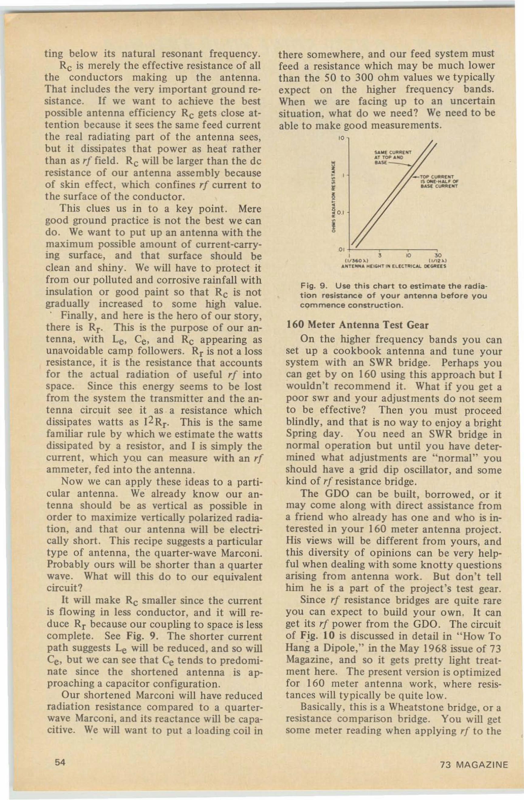
_ TOP CUll IIl "T~ QOOl·H .....F OF.AU CUII1Il lfT
I 3 10 301I/)60 ),. l lOlI2 ),.l
ANUNNA ,;l \lO,;T IN l L( CTR1CAl. ll(GoIIHS
$.&"( C""'" l " TAT TOP AOOD..~-~/
Fig. 9 . Use this chart to estimate tha radiation resistance of your antenna before youcommence construction.
160 Meter Antenna Test GearOn the higher frequency bands you can
set up a cookbook antenna and tune yoursystem with an SWR bridge. Perhaps youcan get by on 160 using this approach but [wouldn't recommend it. What if you get apoor swr and your adjustments do not seemto be effective? Then you must proceedblindly, and that is no way to enjoy a brightSpring day. You need an SWR bridge innormal operation but until you have determined what adjustments are "normal" youshould have a ·grid dip oscillator, and somekind of rf resistance bridge.
The GDO can be built, borrowed, or itmay come along with direct assistance froma friend who already has one and who is interested in your 160 meter antenna project.His views will be different from yours, andthis diversity of opinions can be very helpful when dealing with some knotty questionsarising from antenna work. But don't tellhim he is a part of the project's test gear.
Since r{ resistance bridges are quite rareyou can expect to build your own. It canget its rf power from the GDO. The circuitof Fjg. lOis discussed in detail in "How ToHang a Dipole," in the May 1968 issue of 73Magazine , and so it get s pretty light treatment here. The present version is optimizedfor 160 meter antenna work , where resistances will typically be quite low.
Basically, this is a Wheatstone bridge, or aresistance comparison bridge . You will getsome meter reading when applying r{ to the
there somewhere, and our feed system mustfeed a resistance which may be much lowerthan the 50 to 300 ohm values we typicallyexpect on the higher frequency bands.When we are facing up to an uncertainsituation, what do we need? We need to beable to make good measurements.
'0
ting below its natural resonant frequency.Rc is merely the effective resistance of all
the conductors making up the antenna.That includes the very important ground resistance. If we want to achieve the bestpossible antenna efficiency Rc gets close attention because it sees the same feed currentthe real radiating part of the antenna sees,but it dissipates that power as heat ratherthan as rf field. Rc will be larger than the deresistance of our antenna assembly becauseof skin effect, which confines rf current tothe surface of the conductor.
This clues us in to a key point. Meregood ground practice is not the best we cando . We want to put up an antenna with themaximum possible amount of current-carrying surface, and that surface should beclean and shiny. We will have to protect itfrom our polluted and corrosive rainfall withinsulation or good paint so that Rc is notgradually increased to some high value.. Finally, and here is the hero of our story,
there is Rr. This is the purpose of our antenna, with Le, Ce, and Rc appearing a'unavoidable camp followers. Rr is not a lossresistance, it is the resistance that accountsfor the actual radiation of useful rf intospace. Since this energy seems to be lostfrom the system the transmitter and the antenna circuit see it as a resistance whichdissipates watts as (2 Rr. This is the samefamiliar rule by which we estimate the wattsdissipated by a resistor, and I is simply thecurrent, which you can measure with an rfammeter, fed into the antenna .
Now we can apply these ideas to a particular antenna . We· already know our antenna should be as vertical as possible inorder to maximize vertically polarized radiation, and that our antenna will be electrically short. This recipe suggests a particulartype of antenna, the quarter-wave Marconi.Probably ours will be shorter than a quarterwave. What will this do to our equivalentcircuit?
It will make Rc smaller since the currentis flowing in less conductor, and it will reduce Rr because our coupling to space is lesscomplete. See Fig. 9. The shorter currentpath suggests Le will be reduced , and so willCe, but we can see that Ce tends to predomi·nate since the shortened antenna is approaching a capacitor configuration.
Our shortened Marconi will have reducedradiation resistance compared to a quarterwave Marconi, and its reactance will be capacitive. We will want to put a loading coil in
54 73 MAGAZINE
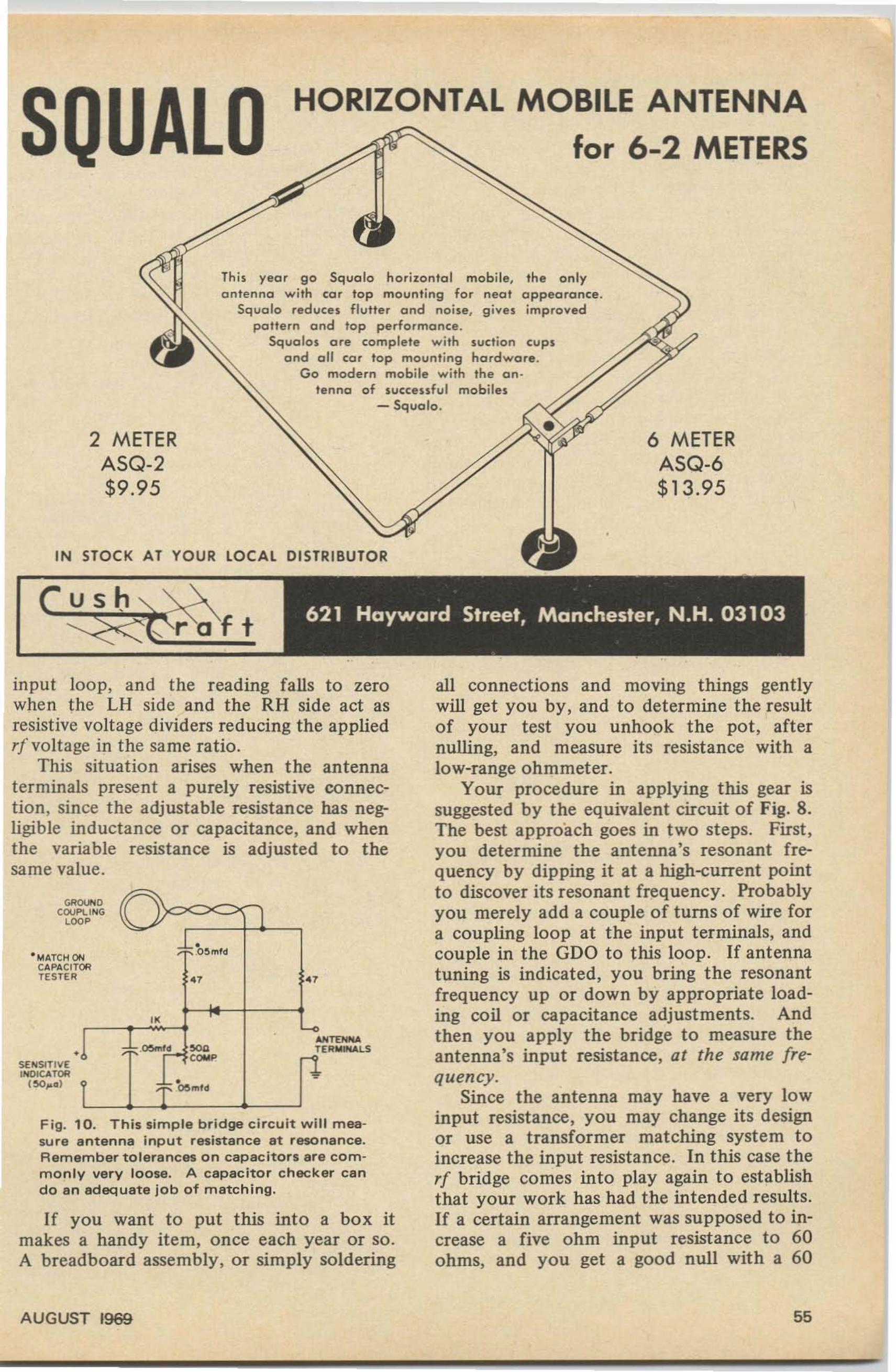
HORIZONTAL MOBILE ANTENNA
for 6-2 METERS
IN STOCK AT YOUR LOCAL DISTRIBUTOR
6 METERASQ-6$13.95
Thi s yea r go Squalo hori zontal mobile. the only
Squa lo red uces fl utter and no ise . g ive s improvedpattern and lo p performonce .
Squa los o re complete wi th suct ion cupsa nd all cor top mounting hardware .
Go modern mobile with the en tenna of succe u fu l mobiles
- Squolo .
2 METERASQ-2$9.95
us
If you want to put this into a box itmakes a handy item, once each year or so.A breadboard assembly, or simply soldering
Fig. 10. This simple bridge circuit will measu re antenna Input resistance at resonance.Remember tolerances on capacitors are commonly very loose. A capacitor checker cando an adequate job of matching.
input loop, and the reading falls to zerowhen the LH side and the RH side act asresist ive voltage dividers reducing the appliedrf voltage in the same ratio.
This situation arises when the antennaterminals present a purely resistive connection, since the adjustable resistance has negligible inductance or capacitance, and whenthe variable resistance is adjusted to thesame value.
all connections and moving things gentlywill get you by, and to determine the resultof your test you unhook the pot , afternulling, and measure its resistance with alow-range ohmmeter.
Your procedure in applying this gear issuggested by the equivalent circuit of Fig. 8.The best approach goes in two steps. First,you determine the antenna's resonant frequency by dipping it at a high-current pointto discover its resonant frequency. Probablyyou merely add a couple of turns of wire fora coupling loop at the input terminals, andcouple in the GDO to this loop. If antennatuning is indicated, you bring the resonantfrequency up or down by appropriate loading coil or capacitance adjustments. Andthen you apply the bridge to measure theantenna's input resistance, at the same frequency.
Since the antenna may have a very lowinput resistance, you may change its designor use a transformer matching system toincrease the input resistance. In this case therf bridge comes into play again to establishthat your work has had the intended results.If a certain arrangement was supposed to increase a five ohm input resistance to 60ohms, and you get a good null with a 60
.u<mo~
TERW....LS
~5 tnld
•~ ...td
"_~d eca
"""
"MATCH ONCAPACITORTESTER
•
""'''''0COUF'LI NGcoo,
SEHSlTlYEINDICATOR
150,.01
AUGUST 1969 55
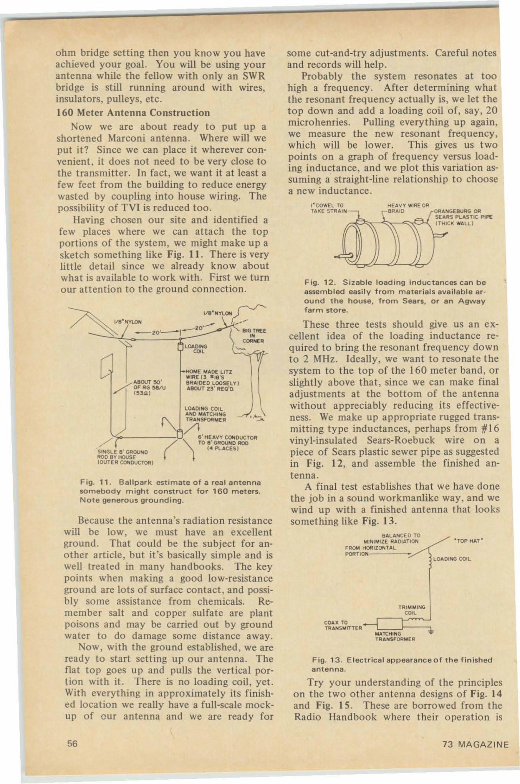
'TOP HAT '
GEBURG ORRS PlASTIC PIPECI( WALl!
LOAOING COIL
HEAVY WIRE 0 "
" 0
~ATt:I1IN G
T"A JoISF()R~ER
TRI~"' I NG
con
BALANCED TO~ IN I~ I ZE RADIATION
FROM HORIZONTALPORTlON- - --;-/
'"-.J.. r" AI rORAN,U
" '\ '\(TH I
~ =r
I' DO WEL TOT.ft..:E STRA
Try your understanding of t he principleso n the two o ther antenna designs of Fig. 14and Fig. 15 . These are borrowed from theRadio Handbo ok where their o peration is
Fig. 13 . Electrical a p peara nce o f t he f in ishedanten na.
Fig. 12 . Si zab le loading inductances can b eassembled easil y from m at erial s available ero u nd t he house, from Sears. o r an Agwayfarm store.
These three tests should give us an excellent idea of the loading inductance required to bring the resonant frequency do wnto 2 MHz. Ideally, we want to resonate thesyste m to the top of the 160 meter band , orsligh tly above that , since we can ma ke finaladjustments at the bottom of t he antennawithout appreciabl y reducing its effectiveness. We make up appropriate rugged transmittin g type inducta nces, perhaps from tl I6vinyl-insulated Sears-Roebuck wire o n apiece of Sears plastic sewer pipe as suggestedin Fig. 12, and assemble the finishe d antenna.
A final test establishes that we have donethe job in a sound workmanlike way, and wewind up with a finished antenna that lookssomething like Fig. 13.
so me cut-and-try adjust rnents , Careful notesand records will help.
Probably the system resonates at toohigh a frequency . After de termining whatthe resonant frequency actually is, we let theto p down and add a loading coil of, say, 20microhenries. Pulling every thing up again,we measure the new resonant frequency,which will be lower . This gives us t wopoints o n a graph of frequency versus loading inductance, and we plot this variation assuming a stra ight-line re lationship to choosea new inductance .
HOME Iol AO£ L1 TZWIRE ( 3 - IS'SBRAIDED LOOSELY )ABOUT U ' REQ'O
LOADINGro,
(
-ZO'
ABOUT eo'./OFRG ~u
/" 1 ( ~Ull
LOAOING COILAN D MATCHI"'" •~TR.I,NSFORMEA ......
/l/ ? - - - - --oIJ. , ' I1EAVY CONDUCTOR/ '1 TO S' GROUND AOO( ~ PlACES )
SINGLE 8 ' GROUND1'lO0 BY HOUSE(OUTE R CONDUCTOR)
Because the antenna's radiation resistancewill be lo w, we must have an excellentground . That could be t he subject for another article , but it's basically simple and iswell treated in many handbooks. The keypoints when making a good lo w-resistanceground are lots of surface contact, and possibly so me assistance fro m che micals. Remember salt and copper sulfate are pla ntpoisons and may be carried o ut by groundwater to do damage so me distance away.
Now, with the ground established, we areready to start setting up o ur antenna. Theflat top goes up and pulls the vert ical po rtion with it. There is no loading coil, yet.With everything in approximately its finished location we really have a full-scale mockup of our antenna and we are ready for
Fig. 11 . Ballpark estimate of a real anten nasomebody might construct fo r 160 m eters.Note generous grounding.
ohm bridge setting then you kno w you haveachieved your goa l. You will be using yourantenna while the fellow with o nly an SWRbridge is still running around with wires ,insulators. pulleys. etc.160 Meter Antenna Construction
Now we are about ready to put up ashortened Marco ni antenna. Where will weput it? Since we can place it wherever convenient, it does not need to be very close tothe transmitter. In fact , we want it at least afew feet from the building to reduce energywasted by coupling into house wiring. Thepossibility of TVl is reduced t oo .
Having chosen our site and identified afew places where we can attach th e topportions of the system, we migh t make up asket ch something like Fig. II. There is verylittle detai l since we already know aboutwhat is available to work with. First we turnour attention to the ground connection.
56 73 MAGAZIN E
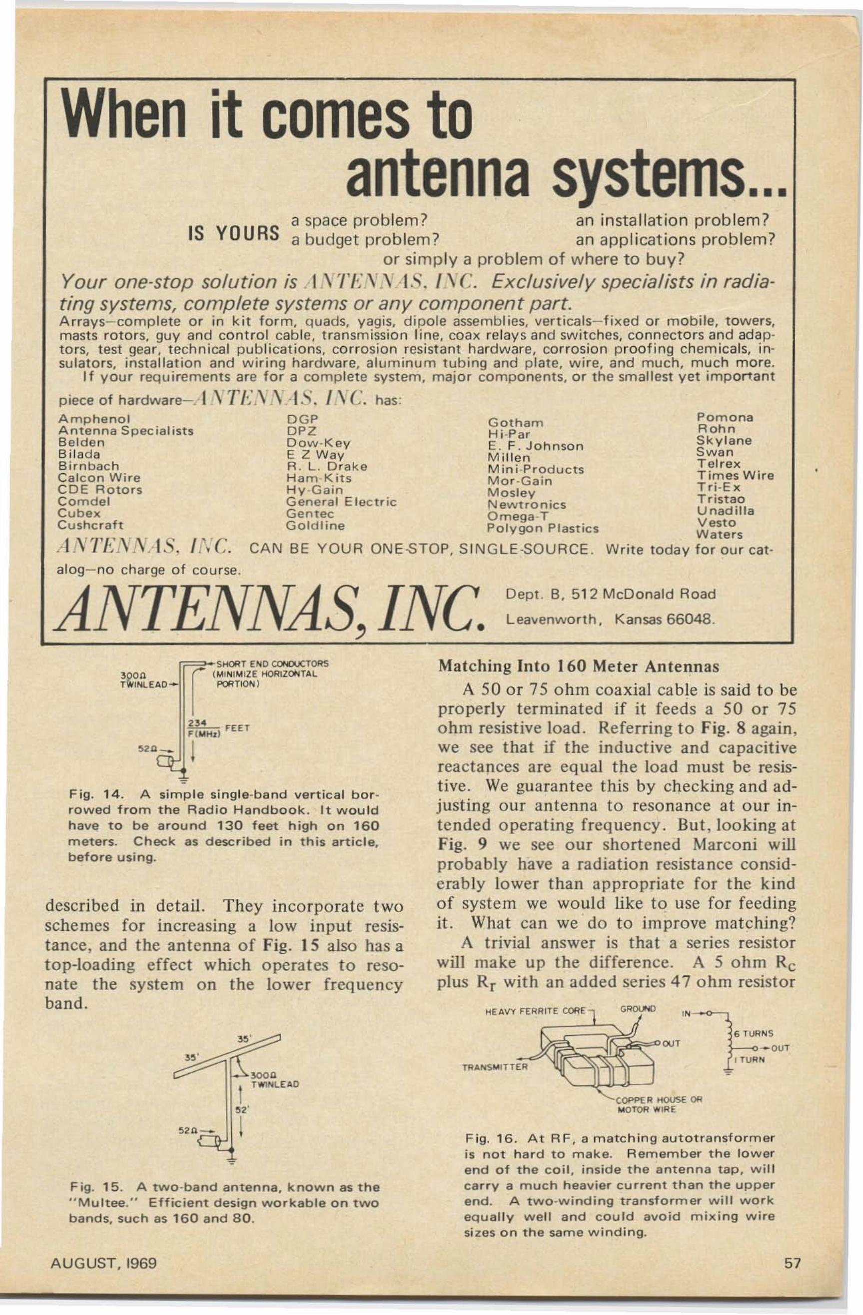
When it comes toantenna systems...
Gotham PomonaHi-Par RohnE. F.Johnson Skylane
Swa nMi llen Tel rexMintPtoducrs Times WireMor ·Gain T ri .ExMosley TristaoNewtrootcs UnadillaO m ega ·TPolygon Plastics Vesto
Wate rsCAN BE YOUR ONE-STOP. SINGLE -SOURCE . Write today fo r ou r cat-
a space problem? an in stallation prob lem?IS YOURS a budget prob lem? an appl icat ions prob lem?
or simp ly a problem of where to buy?Your one-stop solution is , LVTf YS AS. l ,ye . Exclusively specialists in radiating systems, complete systems or any component pert.Arrays-complete o r in ki t fo rm, quads. vaqis. dipole assemblies, verticals-fixed or mobile, towers,masts rotors, guy a nd co nt ro l cab le, transmissio n line, coax relays and switches. connecto rs and adapto rs, test gear, technical publ icat ions, corros ion resist ant hardware. corrosion proofi ng chem icals. insulato rs. installat ion and wiring hardware. alum inum tubing and p late. wire. and much. much m ore.
If your requirements are for a complete system, majo r components, or the smallest yet important
piece of hardware-c-] \ "'I'I,·,\ ,y·I -' . I \ C'. has:Amphenol D GPAntenna Specialists DPZBelden Dow-KeyBi lada E Z WayBirnbach R . L. D rakeCa lcon Wi re Hem.KttsCDE Rotors Hy -GainComdel General ElectricCubex G en t ecCushcraft G oldline
A A T/';'''i\'.' IS. INC.alog-no charge o f course.
ANTENNAS, INC.Dept. B, 512 McDonald Road
Leavenworth, Kansas 66048.
,,' 6 TUR~S
l-~--OUTI TUR~
Matching Into 160 Meter AntennasA 50 or 75 o hm coaxial cable is said to be
properly terminated if it feeds a 50 or 75ohm resistive load . Referring to Fig. 8 again,we see t hat if the inductive and capacitivereactances are equal the load must be resistive. We guarantee this by checking and adjust ing our antenna to resonance at o ur intended operating freq uency . But , looking atFig. 9 we see our shortened Marconi willprobably have a radiation resistance considerab ly lower than appropriate fo r the kindof syste m we would like to use fo r feedingit. What can we do to improve matching?
A trivial answer is that a series resistorwill make up the difference. A 5 ohm Rcplus Rr with an added series 47 ohm resistor
F ig. 1 6 . At R F, a match ing auto t ransfor meris not hard to m ak e. R em ember the lowerend of the co i l , inside the antenna tap, wi llcarry a much heavier current than the upperend. A two-winding transformer will workequally well and could avoid mixing wi resizes o n t he same windi ng.
COPPE R I-!OUSE ORMOTOR "' IRE
HEAVY FERR ITE CORE
>0001T"''''lEAO
" .I
,,'
~2n_
rr=;~Si'4ORT E~D CONDUCTOR'Sr (M I ~I MIZE HORIZONTALI PORTIO~)
U· FH TF (MM I I
I!>2lJ. _
Fig . 1 5 . A two-band antenna, known as the" M u l t ee." Efficient design workable on twobands, such as 16 0 and 80.
Fig. 14. A simp le single-band ver tica l b otrowed fro m the Rad io H and b o o k . It wou ldh av e to be arou nd 130 feet h igh on 160meters. Check as described i n this article.before using.
described in detail. They in corporate t woschemes for increasing a low input resistance, and the antenna of Fig . 15 also has atop-loading effect which operates to resonate the system on the lower frequencyband.
AUG UST. 1969 57
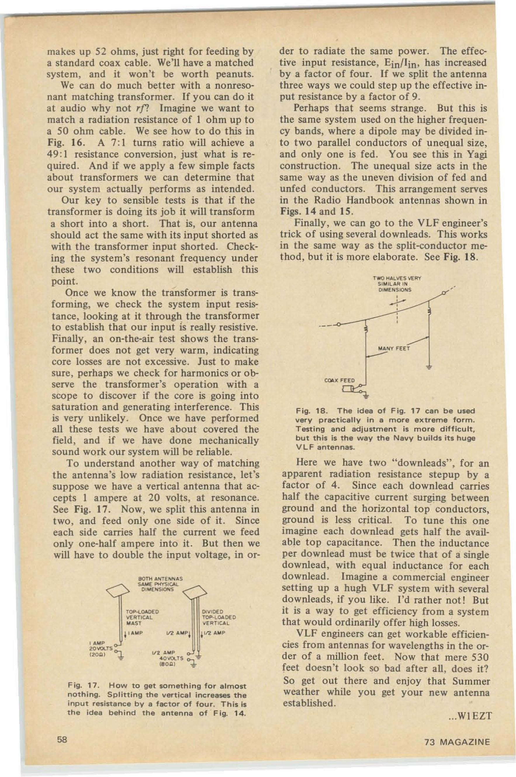
Fig. 17. How to get something for almostnothing. S plitting th e vertical increases theinput res istanc e by a factor of four. This isth e idea behind the antenna of Fig. 14. ...WI EZT
Here we have two "downleads" , for anapparent radiation resistance stepup by afactor of 4 . Since each downlead carrieshalf the capacitive current surging betweenground and the horizontal top conductors,ground is less critical. To tune this oneimagine each downlead get s half the available top capacitance. Then the inductanceper downlead must be twice that of a singledownlead , with equal inductance for eachdownlead . Imagine a co mmercial engineersell ing up a hugh VLF system with severaldownleads, if you like . I'd rather not! Butit is a way to get efficiency from a systemthat would ordinarily offer high losses.
VLF engineers can get workable efficiencies from antennas for wavelengths in the order of a million feet. Now that mere 530feet doesn't look so bad after all , does it?So get out there and enjoy that Summerweather while you get your new antennaestablished.
Fig. 18. The idea of Fig. 17 can be usedvery practically in a more extreme form .Testing and adjustment is more difficult.but this is the way the Navy builds its hugeV L F antennas.
TVII'O HALVES VERYSI "'IL AR INDIM E: NSIONS,
...y,
COAX FH O
"' ANY FE £ T
der to radiate the same power. The effective input resistance, Ein/Iin, has increasedby a factor of four. If we split the antennathree ways we could step up the effective input resistance by a factor of 9.
Perhaps that seems strange. But this isthe same system used on the higher frequency bands, where a dipole may be divided into two parallel conductors of unequal size,and only one is fed. You see this in Yagiconstruction. The unequal size acts in thesame way as the uneven division of fed andunfed conductors. This arrangement servesin the Radio Handbook antennas shown inFigs. 14 and 15.
Finally, we can go to the VLF engineer'strick of using several downleads. This worksin the same way as the split-conductor method, but it is more elaborate. See Fig. 18.
1/2 A"'P'I O'/OLTS 0-. ':"(80'11 ~
BOTM A"'TlN"'ASSAME: PHYSICAl
01 "'E:"'SIO'-IS
TOP-l..OAOEDVE RTICAL"'AST
4'..."'P
I A"'P20llOLTS e>-,(20Q I ...L
makes up 52 ohms, just right for feeding bya standard coax cable. We'll have a matchedsystem, and it won't be worth peanuts.
We can do much better with a nonresonant matching transformer. If you can do itat audio why not rf! Imagine we want tomatch a radiation resistance of I ohm up toa 50 ohm cable. We see how to do this inFig. 16. A 7 : I turns ratio will achieve a49 :1 resistance conversion, just what is required. And if we apply a few simple factsabout transformers we can determine thatour system actually performs as intended .
Our key to sensible tests is that if thetransformer is doing its job it will transforma short into a short. That is, our antennashould act the same with its input shorted aswith the transformer input shorted. Checking the system's resonant frequency underthese two conditions will establish thispoint.
Once we know the transformer is transforming, we check the system input resistance, looking at it through the transformerto establish that our input IS really resistive.Finally, an on-the-air test shows the transformer does not get very warm, indicatingcore losses are not excessive. Just to makesure, perhaps we check for harmonics or observe the transformer's o peration with ascope to discover if the core is going intosaturatio n and generating interference. Thisis very unlikely. Once we have performedall these tests we have about covered thefield , and if we have done mechanicallysound work our system will be reliable.
To understand another way of matchingthe antenna's low radiation resistance, let'ssuppose we have a vertical antenna that accepts 1 ampere at 20 volts, at resonance.See Fig. 17. Now, we split this antenna intwo, and feed only one side of it. Sinceeach side carries half the current we feedonly o ne-half ampere into it . But then wewill have to double the input voltage, in or-
58 73 MAGAZINE
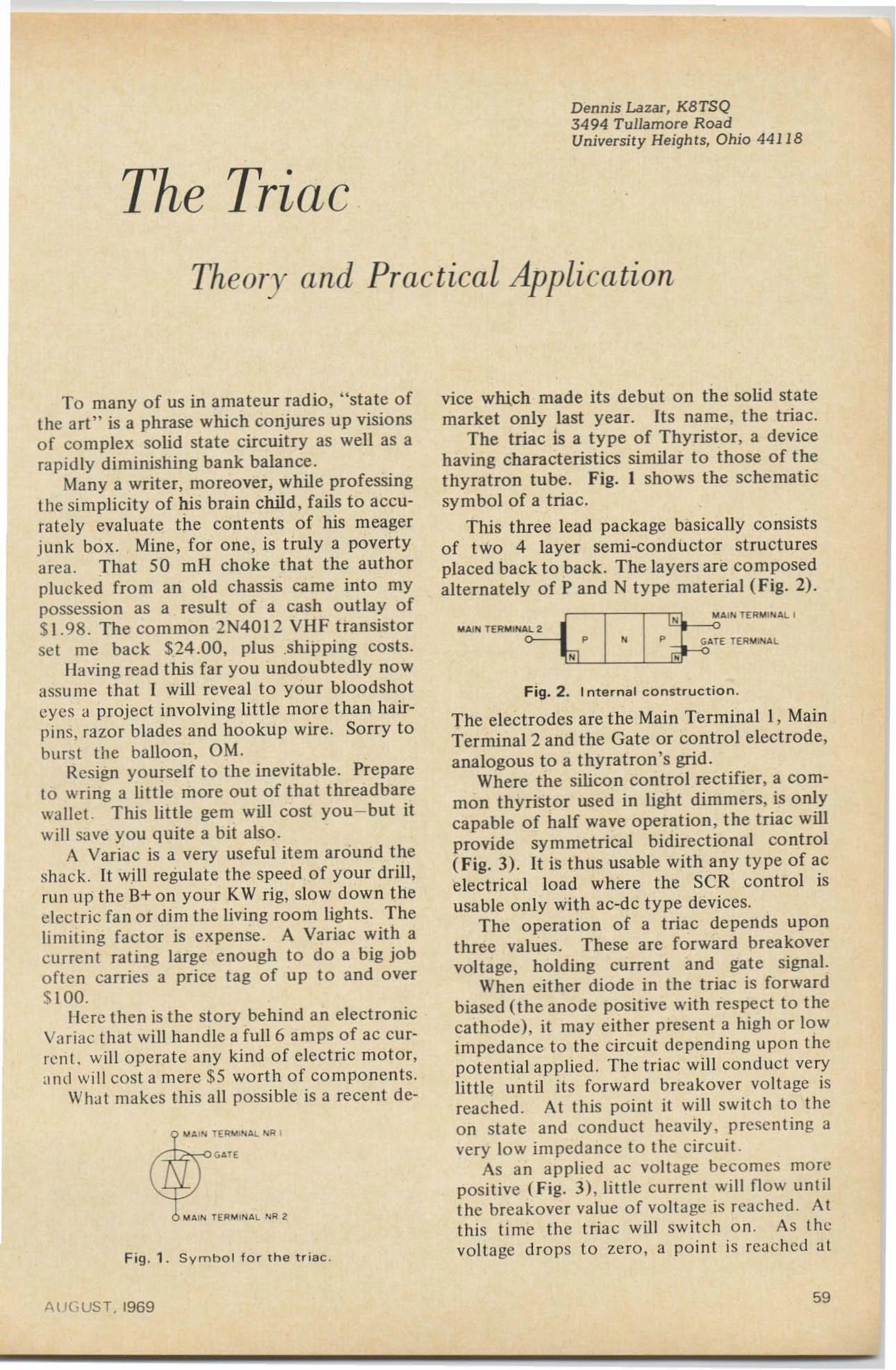
Dennis Lazar, KBTSQ3494 T ullamore RoadUniversi ty Heights, Ohio 44 118
The Triac
Theory and Practical Application
Fig. 2 . 1nternal const ruct io n.
The electrodes are the Main Terminal I , MainTerminal 2 and the Gate or control electrode,analogous to a thyratron 's grid .
Where the silicon control rectifier , a common thyristor used in light dimmers, is onlycapable of half wave operation, the triac willprovide symme trical bidirect ional co nt rol( Fig. 3) . It is thus usable with any ty pe of acelectrical lo ad where the SCR control isusable only with ac-dc t ype devices.
The operation of a triac de pends uponthree values. These arc fo rward brea kovervoltage, holding current and gate signal.
When eit her diode in the triac is fo rwardbiased (the anode positive with respect to thecathode), it may either present a high or lowimpedance to the circuit de pendi ng upo n thepoten tial applied . The triac will cond uct verylittle until its forwa rd breakover voltage isreached. At this po int it will switch to thcon state and conduct heavily , presenting avery low impedance to the circuit .
As an applied ac volta ge becomes morepositive ( Fig. 3), litt le current will fl ow untilthe breakover value of vo ltage is rea ched . Atthis t ime the tria c will switch o n. As t hevoltage drops t o zero , a point is reached at
(J CP'" MAIN TE RM 'N AL I
M AIN TERMINAL 2 0
0"':""- '" p "l ~ GATE T( Rl,loNAL
vice which made its debut on the solid statemarket only last year. Its name, t he triac.
The triac is a ty pe of Thyristor, a devicehaving characteristics similar to those of t hethyratron tube. Fig. I shows the schematicsy mbol of a triac .
This three lead package basically consistsof two 4 layer semi-conductor structuresplaced back to back. The layers are co mposedalterna tely of P and N t ype material ( Fig. 2).
GATE
V A ' ''l
:L;
o,! A' ''l ,.
To many of us in amateur radio , "state ofthe art " is a phrase which conjures up visionso f complex solid state circuit ry as well as arapid ly diminishing ba nk balance.
Many a writer, moreover , while professingthe simplicity of his brain child, fails to accurate ly evalua te the cont ents of his meagerjunk bo x. Mine, for one, is truly a povertyarea . That 50 mil choke that the authorplucked from an old chassis came into mypossession as a result of a cash outlay of$1.98. The com mon 2N4012 VHF transistorset me back $24 .00, plus .shipping costs.
Having read this far you undou btedly nowassume that I will reveal to your bloodshoteyes ;J project involving little more than hairpins, razor blades and hookup wire. Sorry toburs t th e balloon, OM.
Resign yourself to the inevitable. Prepareto wring a little more out of that threadbarewa llet. This little gem will cost you-but itwill save you quite a bit also .
A Variac is a very useful item around t heshac k. It will regulate the speed of your drill ,run up the B+ on your KW rig, slow down theelectric fa n or dim the living room lights. Thelimiting factor is expense . A Variac with acurrent rat ing large enough to do a big jobofte n carries a price tag of up to and over$100.
Here then is the story behi nd an elect ro nicVariac that will han dle a fu ll 6 amps of ac cu rrent. wi ll o pera te any kind of elect ric mot or,and will cost a mere $5 wo rth of co mponents .
What makes this all possible is a recent de-
Fig . 1 . Symhol fo r th e t riac .
A UG UST, I96959
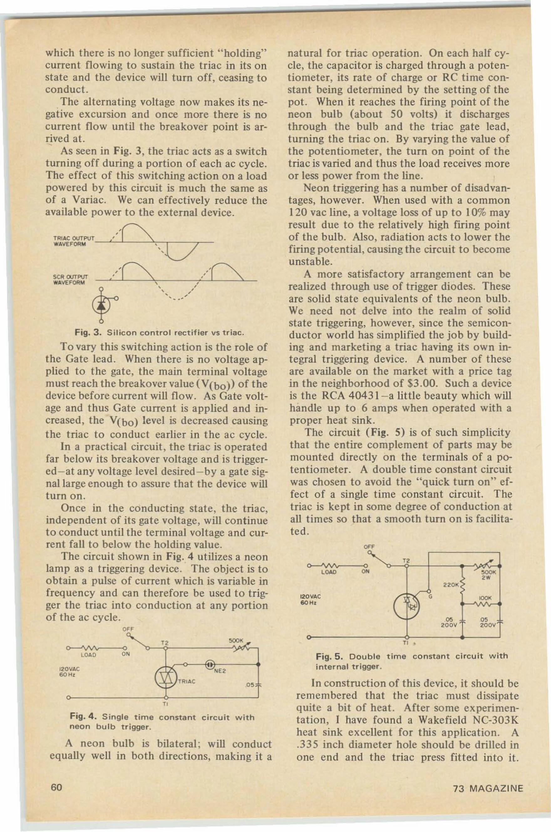
,
•,
'"
ecc«,.
05 .05200V 200'1
2201<
120VACW H.
natural for triac operation. On each half cycle . the capacitor is charged through a potentiometer. its rate o f charge or RC time constant being determined by the sett ing of thepot. When it reaches the firing point of theneon bulb (about 50 volts) it dischargesthrough the bulb and the triac gate lead,turning the triac on. By varying the value ofthe potentiometer, the turn on point of thetriac is varied and thus the load receives moreor less power from the line.
Neon triggering has a number of disadvantages, however. When used with a common120 vac line, a voltage loss of up to 10% mayresult du e to the relatively high firing pointof the bulb. Also, radiation acts to lower thefiring potential. causing the circuit to becomeunstable.
A more satisfactory arrangement can berealized through use of trigger diodes. Theseare solid state equivalents of the neon bulb.We need not delve into the realm of solidstate triggering, however, since the semiconductor world has simplified the job by building and marketing a triac having its own integral triggering device. A number of the seare available on the market with a price tagin the neighborhood of $3.00. Such a deviceis the RCA 40431 -a little beauty which willhandle up to 6 amps when operated with aproper heat sink.
The circuit (Fig. 5) is of such simplicitythat the entire co mplement of parts may bemounted directly on the terminals of a potentiometer. A double time constant circuitwas chosen to avoid the "quick turn on" effect of a single time constant circuit. Thetriac is kept in some degree o f conduction atall tim es so that a smooth turn on is facilitated .
•
,,,TRIAC OUTPUT_~----'__-'c-r__r-_WAVEI'QRM
which there is no longer sufficient "holding"current flowing to sustain the triac in its onstate and the device will turn off. ceasing toconduct.
The alternating voltage now makes its negative excursion and o nce more there is nocurrent fl ow until the breakover point is arrived at.
As seen in Fig. 3, the triac acts as a switchturning off during a portion of each ac cycle.The effect of this switching action on a loadpowered by this circuit is much the same asof a Variac. We can effectively reduce theavailable power to the external device.
Fig. 3. S il icon cont ro l rectifier vs tria c.
To vary this switching action is the role o fthe Gate lead . When there is no voltage applied to the gate, the main terminal voltagemust reach the breakover value (V(bo» of thedevice before current will fl ow . As Gate voltage and thus Gate curre nt is applied and increased, the V(bo) level is decreased causingthe triac to conduct earlier in the ac cycle.
In a practical circuit. the triac is operatedfar below its breakover voltage and is triggered-at any voltage level desired -by a gate signallarge enough to assure that the device willturn on.
Once in the conducting state, the triac.independent o f its gate voltage, will continueto conduct until the terminal voltage and current fall to below the holding value.
The circuit shown in Fig' ,4 utilizes a neonlamp as a triggering device. The object is toobtain a pulse o f current which is variable infrequency and can therefore be used to trigger the triac into co nduction at any portionof the ac cycle .
SCR OUTPIJTW/lVE I'QRM
'0'"
Fig. 4. S ingle tim e constant circuit withneon bul b t r igge r.
A neon bulb is bilate ral: will conductequally well in both directions, making it a
In construction of this device, it should beremembered that the triac must dissipatequite a bit o f heat. After so me experimentation, I have found a Wakefield NC-303Kheat sink excellent for this a pplicatio n. A.335 inch diameter hole should be drilled inone end and the triac press fitted into it.
Fig. 5. Double time constant circuit w ithinternal trigger.
n •
0 'TRI AC""'7
120VACW H,
60 73 MAGAZINE
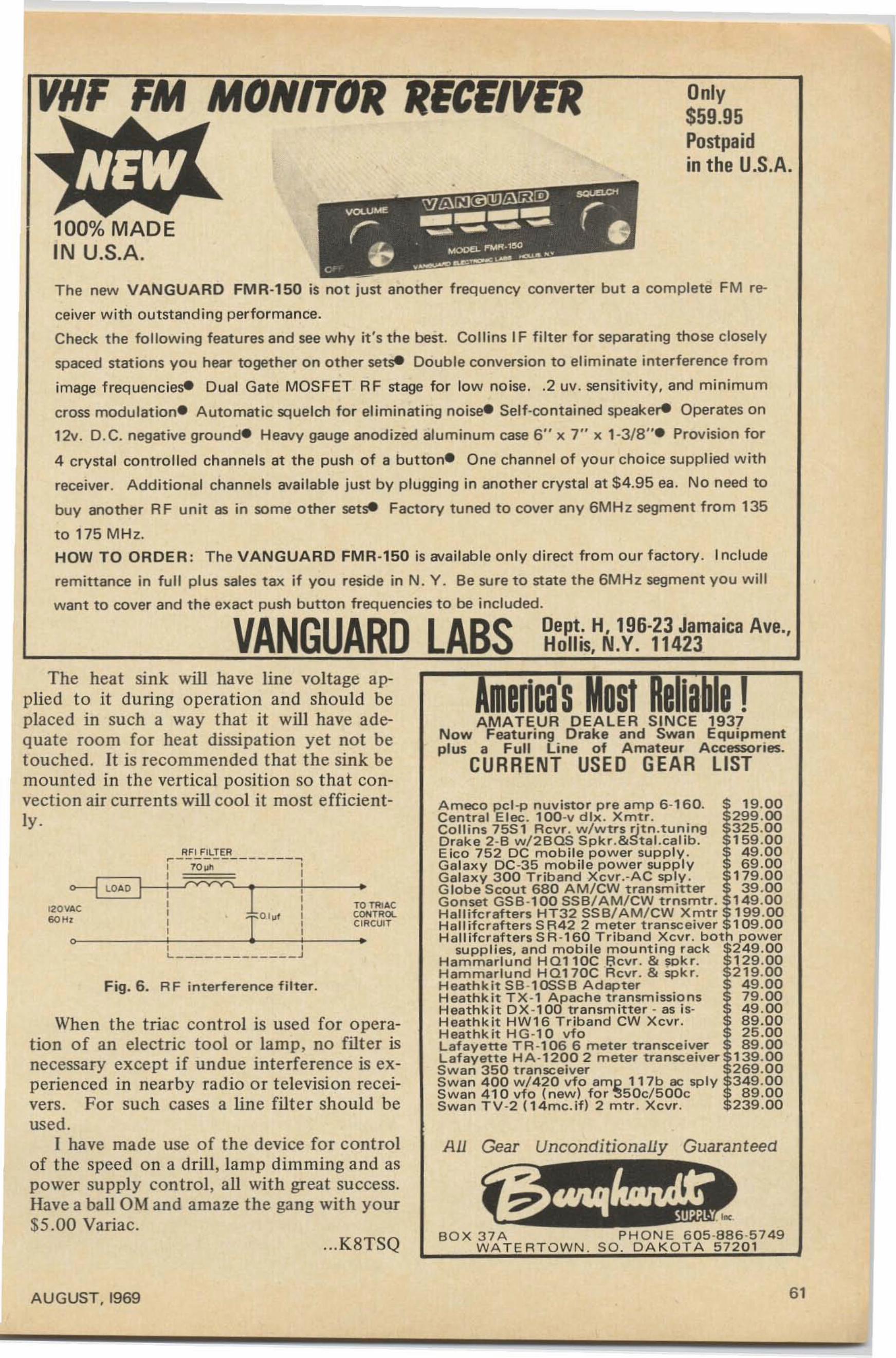
VHF FM MONITOR RECEIVER
100% MADEIN U.S.A.
Only$59.95Postpaidin the U.S.A.
The new VANGUARD FMR·150 is no t just another f requency converter but a complete FM re
ceiver wi t h outstandi ng perfo rmance.
Check the fo llowing featu res and see w hy it's the best . Collins IF fi lter fo r separating those closely
spaced stat ions you hear together on other setse Double conversion to elim inate interference from
image trequenclese Dual Gate MOSFET RF stage for low noise. .2 uv. sensit ivity. and minimum
cross modutaticne Automatic squelch f or eliminati ng nolsee Self-contained soeekere Operates on
12v. D.C. negative ground- Heavy gauge anod ized aluminum case 6" x 7" x 1-3/8". Provision for
4 crysta l con t ro lled chan ne ls at the push o f a button- O ne channel o f yo ur choice supplied with
receiver. Add itio nal c han ne ls ava ilab le just by p lugg ing in another c rystal at $4.95 ea. No n eed to
buy another RF unit as in some o t he r setse Fa ct o ry tuned to cove r any 6MHz segment from 135
to 175 M Hz.
HOW TO ORDER : T he VANGUARD FMR·150 is ava ila bl e o n ly d irect from our factory . Include
remittance in full plus sales tax if you resid e in N. Y . Be sure to state the 6MHz segment you will
want to cover and t he exact push button freq uencies to be included.
VANGUARD LABS Dept: H, 196-23 Jamaica Ave.,Hollis, N.Y. 11423
F ig . 6. RF in t erle re nce f ilter.
PH ON E 6 05 -8 8 6 -5 7 49SO . DAKOTA 57201
BOX 37AWA TERTOWN.
mericasMost Reliable'AMATEUR DEALER SINCE 1937
No w Featuring Drake a n d Swan Equipmentplus a Full Line of A mateur Accessories.
CURRENT USED GEAR LIST
All Gear Unconditionally Guaranteed
Ameco pet -e nuvistor pre amp 6 -160 . 19.00Central Elec . 100-v d tx . Xmtr. 299 .00Collins 75S1 Rcvr. w/wtrs rjt n.tuning 325.00Drake 2-B w/2BQS Spkr.&Stal.calib. 159 .00Eico 752 OC mobi le power sup p ly . 49.00Ga laxy OC ·35 m o bil e po wer supp ly 69 .00Ga lax y 3 00 T rib and Xcvr.-AC sply . 179 .00G lobe Scout 680 AM/ CW transmitter 39 .00Gonset GSB -100 SSB/AM/CW trnsmtr. 149.00Ha ll ifcrafters HT32 SSB/AM/CW Xm t r 199 .00Ha ll ifcrafters SR42 2 meter transceiver 109 .00Hallifcrafters SA -1 60 T riband Xcv r. bo t h power
supplies. a nd mo bil e mou nt ing rack 2 49.00Ha m ma rlu nd H Q110C Bcvr , & sekr. 129.00Hammarlund HQ170C Rcvr. & sckr. 219.00Heathkit S8 ·1ooSB Adapter 49.00Heathk it TX-1 Apache t ra nsm issions 79.00Heathk it O X-100 tr a nsm itter - as is- 49 .00H eathkit HW1 6 Triband CW Xcvr . 89.0 0Heathkit HG·l 0 vfo 25.0 0Lafa ye tte T R -10 6 6 meter t ra nsce iver 89.00Lafayette HA·120 0 2 meter transceiver 139.00Swan 350 tra nsceiver 269.00Swan 400 w / 420 vtc amp 11 7 b ac sp ly 349.00Swan 410 vfo ( new) for ~50c/500c 89.00Swan TV -2 (14mc.if) 2 m t r . Xcvr . 239 .00
•
RFI FILTER...-------------....: 70 ull Il ~--+! --: 1 : ro ~AC: I 0 1uf
1 r:l~'f, -----i'--~, ,L J
o
0---4 LO AD
120 VAC
"'"'
When the t riac control is used fo r operation of an electric tool or lamp , no filter isnecessary except if undue interference is experienced in nearby radio o r t elevision receivers . For such cases a line filte r should beused .
I have made use of the device for controlof the speed on a drill, lamp dimming and aspower supply control, all with great success.Have a ball OM and amaze the gang with your$5 .00 Variac.
...K8T SQ
The heat sink will have line voltage applied t o it during operation and should beplaced in such a way that it will have adequate room for heat dissipation yet not betouched. It is recommended that the sink bemounted in the vertical position so that convection air currents will cool it most efficiently.
AUGUST. 1969 6 1
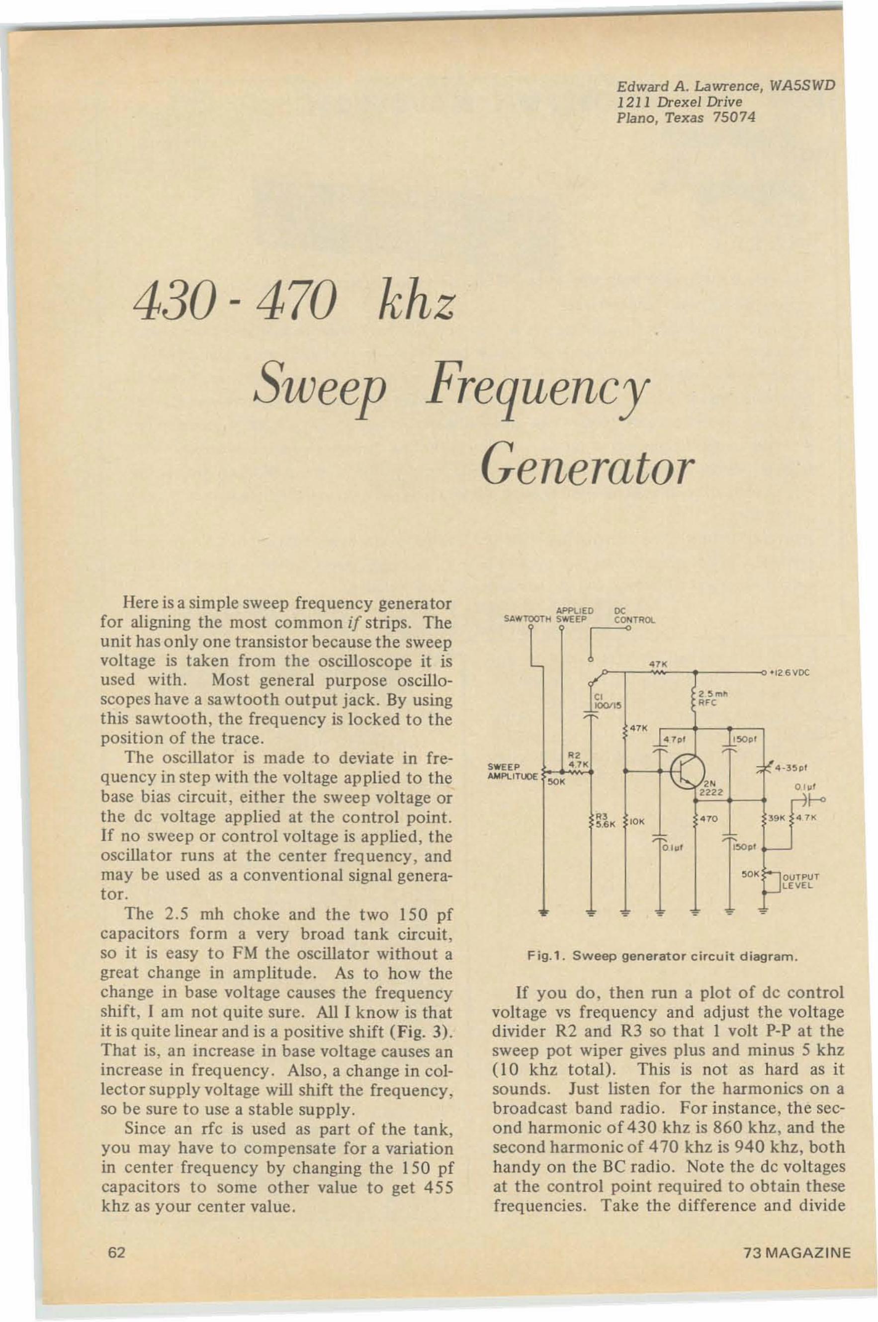
Edward A. Lawrence, WASSWD1211 Drexel DrivePlano, Texas 75074
430 - 470 khz
Sweep Frequency
Generator
Fig.1. Sweep generator circuit diagram .
APPliED DCSAWTOOTH SWEEP COIIITROt.
If you do, then run a plot of de controlvoltage vs frequency and adjust the voltagedivider R2 and R3 so that I volt P-P at thesweep pot wiper gives plus and minus 5 khz(IO khz total). This is not as hard as itsounds. Just listen for the harmonics on abroadcast band radio . For instance, the second harmonic of 430 khz is 860 khz, and thesecond harmonic of 470 khz is 940 khz, bothhandy on the Be radio. Note the de voltagesat the control point required to obtain thesefrequencies. Take the difference and divide
urt,
ocr m
-rae v
"<2 :;m~
~IOOfl:; '",C
m
"~7PI ~~PI
'" t 4 ·3 :;p'
""~
2222
" ro« '" '" •:;.6K
o 1111 l:;opl
' 0'b~UTPLEVE
• • • - - •
SWEEPAMPLITUDE
Here is a simple sweep frequency generatorfor aligning the most common if strips. Theunit has only one transistor because the sweepvoltage is taken from the oscilloscope it isused with . Most general purpose oscilloscopes have a sawtooth output jack. By usingthis sawtooth, the frequency is locked to theposition of the trace.
The oscillator is made to deviate in frequency in step with the voltage applied to thebase bias circuit , either the sweep voltage orthe de voltage applied at the control point.If no sweep or control voltage is applied, theoscillator runs at the center frequency. andmay be used as a conventional signal generator.
The 2.5 mh choke and the two 150 pfcapacitors form a very broad tank circuit,so it is easy to FM the oscillator without agreat change in amplitude. As to how thechange in base voltage causes the frequencyshift , I am not quite sure. All I know is thatit is quite linear and is a positive shift (Fig. 3).That is, an increase in base voltage causes anincrease in frequency. Also, a change in collector supply voltage will shift the frequency,so be sure to use a stable supply.
Since an rfc is used as part of the tank,you may have to compensate for a variationin center frequency by changing the 150 pfcapacitors to some other value to get 455khz as your center value.
62 73 MAGAZINE
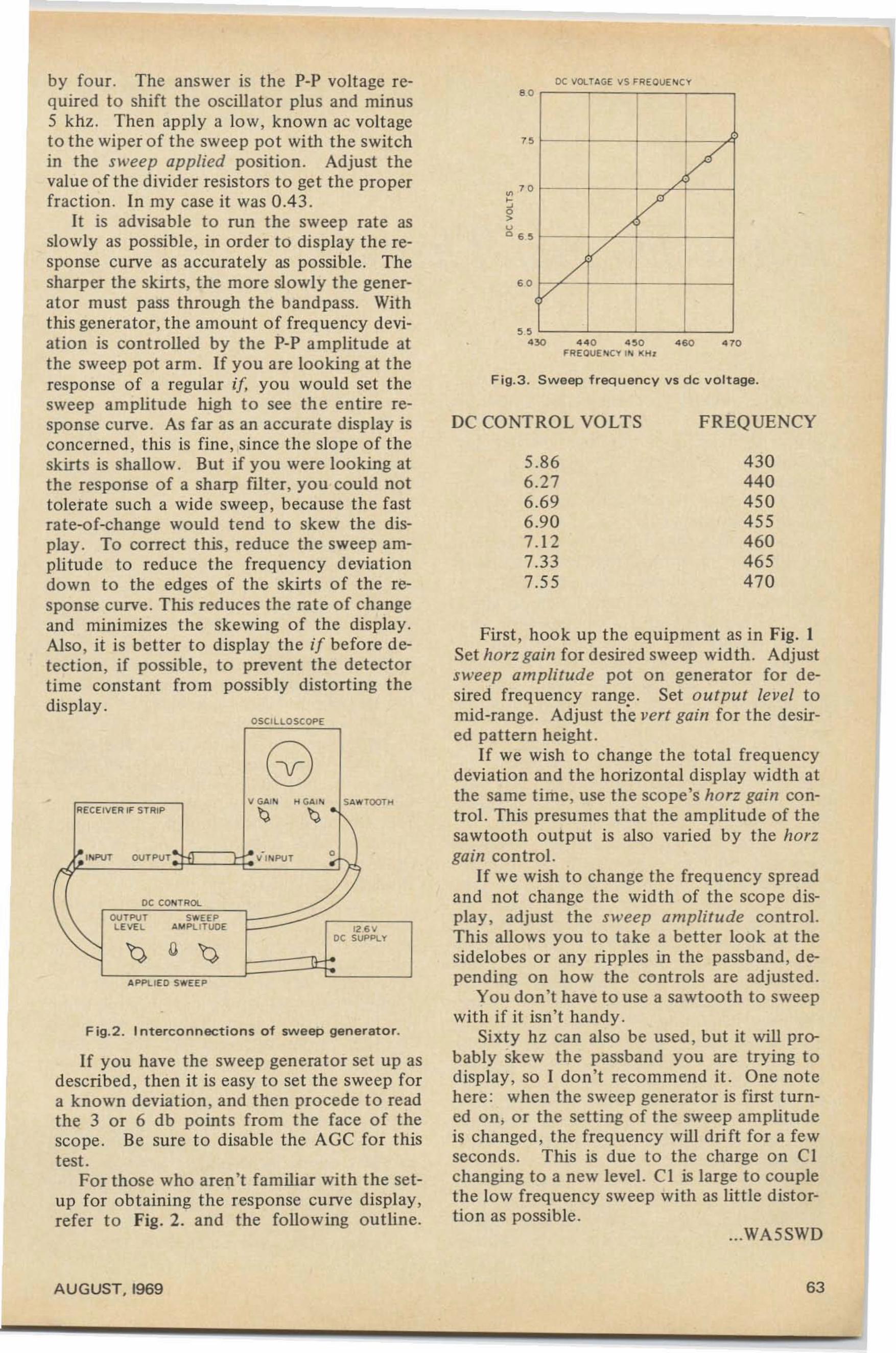
4 30440450455460465470
FREQUENCY
I
1//
V/
V/
V
5.866.276.696.907.127.337.55
DC CONTROL VOLTS
Fig.3 . Sweep f requency vs dc vo ltage.
' 0
OC VOLT4G€ 'IS HI€OUEt<l CY
First , hook up t he equipment as in Fig. ISet horz gain for desired sweep width . Adjustsweep amplitude pot on generator for desired freq uency range. Set output level tomid-range. Adjust the vert gain for the desired pattern height.
If we wish to cha nge the total freq uencydevia tion and the horizontal display width atthe same time, use the sco pe's harz gain cont rol. This presumes that the amplitude of thesawtooth o utput is also varied by the harzgain control.
If we wish to cha nge the frequency spreadand not change t he width of the scope display, adjust the sweep amplitude control.This allows you to take a better look at thesidelobes or any ripples in the passband, depending on how the controls are adjusted.
You don't have to use a sawtooth to sweepwith if it isn ' t handy.
Sixty hz can also be used , but it will probably skew the passband you are trying todisp lay , so I don't recomm end it. One notehere : when the sweep generator is first turned on, or the setting of the sweep amplitudeis cha nged, the frequency will drift for a fewseconds. This is due to the charge on CIchanging to a new level. CI is large to couplethe low frequency sweep with as lit tle distortion as possible.
"4 30 440 4 $ 0 4 60 4 10FIlEOlJE I<l CY II<l II HI
' 0
...WA5SWD
12 6 '0'OC SUPPLY
OSCILLOSCOPE
V INPUT
V GAIN H G.a., N SAwToon<
tJ tJ
OU TPU T
APp!. IEO SWEEP
L EV£L AMPLl TUOE
DC CONTROL
OUTPU T SWEEP
F ig.2 . I nt erco nnection s of sweep generator.
RECEIVER IF STRIP
If you have the sweep generator set up asdescribed , the n it is easy to set the sweep fora known deviation , and then precede to readthe 3 or 6 db points from the face of thesco pe . Be sure to disable the AGC for thistest.
For those who aren't fam iliar with the setup for obtaining the response curve display,refer to Fig. 2. and the following outline.
by fou r. The answer is the POp voltage required to shift the oscillator plus and minus5 khz . Then appty a low, known ac voltageto the wiper of the sweep pot with the switchin the sweep applied position . Adjust thevalue of the divider resistors to get the properfraction. In my case it was 0 .43 .
It is advisable to run the sweep rate asslowly as possible, in order to dis play the response curve as accurately as possible. Thesharper the skirts, the more slowly the generator must pass through the band pass. Withthis generato r, the amount o f frequency deviation is controlled by the pop amplitude atthe sweep pot arm . If you are looking at t heresponse of a regular if, you would set thesweep amplitude high to see the entire response curve . As far as an accurate display isconcerned, this is fine , since the slope of theskirts is shallow . But if you were loo king atthe response of a sharp filter, you could nottolerate suc h a wide sweep, because the fastrate-of-change would t end to skew the display . To correct this , reduce the sweep amplitude to reduce the frequency deviationdown to the edges of the skirts of the response curve. This reduces the rate of changeand minimizes the skewing of the display.Also, it is better to display the if before detection, if possible, to prevent the detectortime constant from possibly distorting thedisplay.
•
AUGUST. 1969 63
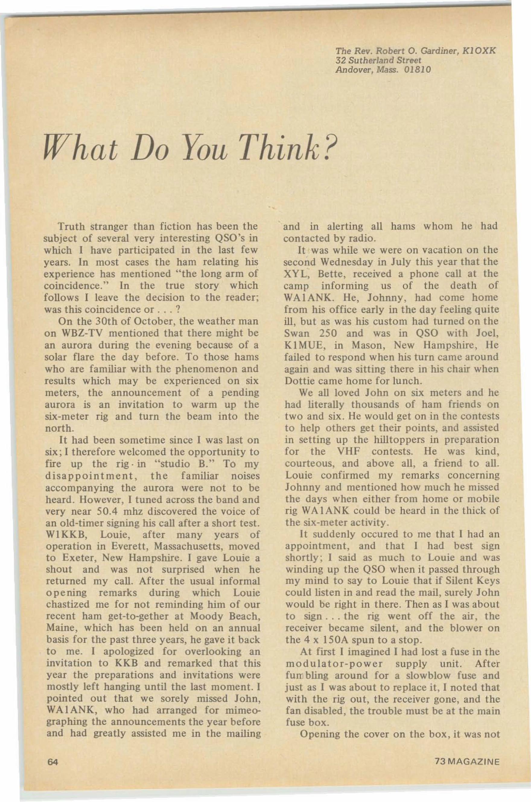
The Rev. Robert O. Gardiner, Kl0XK32 Sutherland StreetAndover, Mass. 01810
What Do You Think?
Truth stranger than fiction has been thesubject of several very interesting QSO's inwhich I have participated in the last fewyears. In most cases the ham relating hisexperience has mentioned "the long arm ofcoincidence:' In the true story whichfollows I leave the decision to the reader;was this coincidence or ... ?
On the 30th of October, the weather manon WBZ-TV mentioned that there might bean aurora during the evening because of asolar flare the day before. To those hamswho are familiar with the phenomenon andresults which may be experienced on sixmeters, the announcement of a pendingaurora is an invitation to warm up thesix-meter rig and turn the beam into thenorth.
I t had been sometime since I was last onsix; I therefore welcomed the opportunity tofire up the rig· in "studio B." To mydisappointment, the familiar noisesaccompanying the aurora were not to beheard. However, I tuned across the band andvery near 50.4 mhz discovered the voice ofan old-timer signing his call after a short test.WI KK B, Louie, after many years ofoperation in Everett, Massachusetts, movedto Exeter, New Hampshire. I gave Louie ashout and was not surprised when hereturned my call. After the usual informalopening remarks during which Louiechastized me for not reminding him of ourrecent ham get-to-gether at Moody Beach,Maine. which has been held on an annualbasis for the past three years, he gave it backto me. I apologized for overlooking aninvitation to KKB and remarked that thisyear the preparations and invitations weremostly left hanging until the last moment. Ipointed out that we sorely missed John,WA IANK, who had arranged for mimeographing the announcements the year beforeand had greatly assisted me in the mailing
64
and in alerting all hams whom he hadcontacted by radio.
It was while we were on vacation on thesecond Wednesday in July this year that theXY L, Bette, received a phone call at thecamp informing us of the death ofWA IANK. He, Johnny, had come homefrom his office early in the day feeling quiteill, but as was his custom had turned on theSwan 250 and was in QSO with Joel,K I MUE, in Mason, New Hampshire, liefailed to respond when his turn came aroundagain and was sitting there in his chair whenDottie came home for lunch.
We all loved John on six meters and hehad literally thousands of ham friends ontwo and six. He would get on in the conteststo help others get their points, and assistedin setting up the hilltoppers in preparationfor the VHF contests. He was kind,courteous, and above all. a friend to all.Louie confirmed my remarks concerningJohnny and mentioned how much he missedthe days when either from home or mobilerig WAIANK could be heard in the thick ofthe six-meter activity.
It suddenly occured to me that I had anappointment, and that I had best signshortly; I said as much to Louie and waswinding up the QSO when it passed throughmy mind to say to Louie that if Silent Keyscould listen in and read the mail, surely Johnwould be right in there. Then as I was aboutto sign . . . the rig went off the air, thereceiver became silent, and the blower onthe 4 x 150A spun to a stop.
At first I imagined I had lost a fuse in themodulator-power supply unit. Afterfum bling around for a slowblow fuse andjust as I was about to replace it, I noted thatwith the rig out, the receiver gone, and thefan disabled, the trouble must be at the mainfuse box.
Opening the cover on the box, it was not
73 MAGAZINE
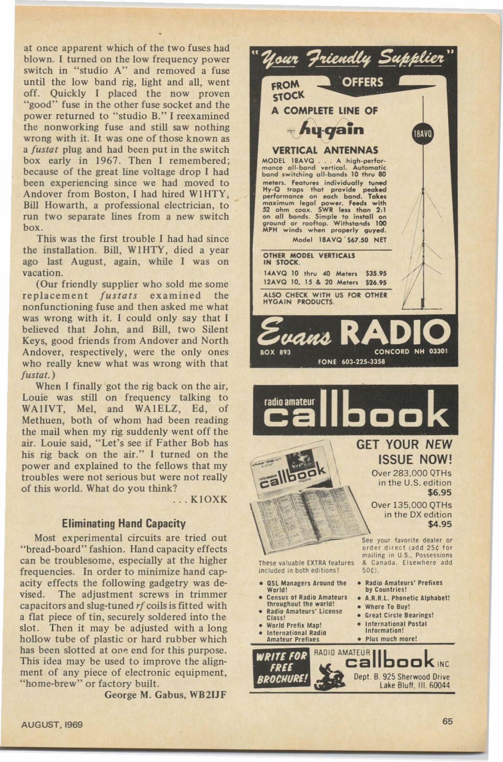
•
•
• Rad io Amateurs' Prefixesby Co untr ies!
II A.R .R .L Phonetic Alphabet !• Where To 8uy!• Great Circle Bea rings!• Internation al Postal
Information!• Plus much more!
GET YOUR NEWISSUE NOW!
Over 283.000 QTHsin the U.S. edition
$6.95
Over 135.000 QTHsin the DX edition
$4.95
, . RAD IO AMATE UR 116 k~
ca 00 INC
Dept. B. 925 Sher wood Drivelake Bluff. III . 60044
OTHER MODEL VERTICALSIN STOCK.
I"AVQ 10 th ru "0 Meten $35.9512AVQ 10, 15 & 20 Mllten $26 .95
ALSO CHECK WITH US FOR OTHERHYGAI N PRODUCTS.
fROMSlOCKA COMPLETE LINE Of
1\ r ."'\...lIq ·q a m
~
VERTICAL ANTENNASMODEL 18AVQ ... A high. perfo r.monce oil-bond verti cal. Aut omat icbond sw itching all-bonds 10 thru 80meten. features individually tunedHy-Q traps that provide peakedperformance on ea ch band. Tak.. \max imum legal power. Feeds with I52 ohm (oall. SWR leu tha n 2,1on all bands. Simple to insta ll onground or rooftop. With.to"ds 100MPH wind. when properly guyed.
Model 18A VQ ' $67.50 NET
II QSL Managers Around theWorld!
II Census of Radio Amateursth roughout the world!
II Radio Amateurs' LicenseClass!
II World Prefi x Map!II Internat ional Radio
Amateur Prefixes
See your favorite dealer ororde r d ir ec t (ad d 25 ¢ f ormailing in U,S., Possessions
These va luable EXTRA features & Canada . El sewher e addincluded in both edmons t SOC ).
WRITIFDRFREI
BRDCI/UH!
at once apparent which of the two fuses hadblown. I turned on the low frequency powerswitch in "studio A" and removed a fuseuntil the low band rig, light and all, wentoff. Quickly I placed the now proven"good" fuse in the other fuse socket and thepower returned to "stud io B," I reexaminedthe nonworking fuse and still saw nothingwrong with it. It was one of those known asa [ustat plug and had been put in the switchbox early in 1967. Then I remembered;because of the great line voltage drop I hadbeen experiencing since we had moved toAndover fro m Boston, I had hired WI HT Y,Bill Howarth, a professional electrician, torun two separate lines from a new switchbox .
This was the first t rouble I had had sincethe installation. Bill, WI HTY , died a yearago last August, again, while I was onvacation.
(Our friendly supplier who sold me somerep lacement [u s t a t s examined thenonfunctioning fuse and then asked me whatwas wrong with it. I could only say that Ibelieved that Jo hn, and Bill, two SilentKeys, good friend s from Andover and NorthAndover, respectively , were the only oneswho really knew what was wrong with that[ustat. )
When I finally got the rig back on the air,Louie was still on frequency talking toWAlIVT, Mel, and WA IELZ, Ed, ofMet huen, both of whom had been readingthe mail when my rig suddenly went off theair . Louie said, "Let's see if Father Bob hashis rig back on the air." I turned on thepower and explained to the fellows that mytroubles were not serious but were not reallyof this world. What do you think?
. .. KIOXK
Eliminating Hand CapacityMost experimental circuits are tried out
"bread-board" fashion . Han d capacity effectscan be troublesome, especially at the higherfrequencies . In order to minimize hand capacity effects the following gadgetry was devised . The adjustment screws in trimmercapacitors and slug-tuned rf coils is fitted witha flat piece of tin , securely soldered into theslot. Then it may be adj usted with a longhollow tube of plastic or hard rubber whichhas been slotted at OI1~ end for this purpose .This idea may be used to im prove the alignment of any piece of electronic eq uipment,"home-brew" or factory built .
George M. Gabus, WB2IJF
AUGUST. 1969 65
Dave Mann, K2AGZOne Daniel LaneKinnelon, New Jersey 07405
Leaky Lines
To all of you who served in the Armyduring World War II as I did, it won't benecessary to explain the term "latrinelawyer." Those who have no first handacquaintance with this ubiquitous charactermay know that he is someone who knowseverything about everything. He doesn'tmind telling anybody within earshot exactlywhat to do, when and how to do it, andwhy. If you dig beneath the superficialveneer of this specimen, you will find a fakerand charlatan, possessing what Oscar Levantonce called a smattering of ignorance.Armed usually with only the sketchiest sortof information, he expands it with a tenuousstructure of half-truth, innuendo, rumor andimplication. He will fasten onto you likeSinbad's old man of the sea, and will neverlet you go, haranguing you till your earsring. The inexperienced, the meek and thegullible ; these are his " pigeons." He is one ofnature's true phenomena, first, last andalways, a phoney!
Ham radio is not immune. We, like theArmy, have our share of "bathroom barristers," who may be found, holding forth onthe airwaves, counseling all their starry-eyedadmirers. Impressionable beginners, ingenuous and naive ; more mature persons withfancied grievances and gripes; the inarticulate and prejudiced seeking a voice; misfitswho revel in divisiveness; all these gatheraround his feet, drinking it all in.
There 's just one fatal flaw in this idyllicscene. The guy doesn't know what he'stalk ing about. It's all a mish-mash of misinformation, without a scintilla of creditablefa ct to back it up. Here are some commonexamples of his hogwash.
." wouldn't use an electronic keyer for allthe rice in China. They make everybodysound just like a tape machine. Why, youlose your identity completely . Give me thegood old bug every lime."
66
What hokum! There's more bad sendingon bugs, side-swipers and cootie keys thanyou can shake a stick at. If a banana-boatswing is supposed to be a mark of identification, it escapes me. It doesn't make forindividuality of fist , as much as it demonstrates little or no concept of the sound oftrue CWo Moreover, characteristic individuality of spelling, punctuation, word usageand other unique peculiarities are maintained regardless of the sending instrument.What we need are more electronic keyers,not fewer. Perhaps this would clear up so meof the horrendous stuff that's been passingfor CW for a long time. In any case, it wouldhelp diminish that atrocious synco patedswing, and reduce it to a passably tolerable
• •rmrumum ." I' m not interested in having broad
casting quality audio. What really counts iscommunication. That's the name of thegame. Boy, when there's a pile-up, I justcrank up my Whatziss Mark Ill, and turn thegain wide open. I like to watch those needlesjump. Then I know the DX station is goingto copy."
Yes, and so will everyone else withintwenty khz, plus or minus. What can I sayabout this guy, except that essentially he'sjust a pig who doesn't consider otherpeople's rights at all. His trademarks areover-modulation , audio distortion, flat-topping, unwanted .hash and spurious radiations, and an abusive attitude toward anyonewho tries to suggest that he cut back on hiszain a bit. Brother, how wrong can you be?
"You guys are not on frequency. I'mcrystal contro lled, so I know I'm on frequency."
Not a single word about whether thatcrystal is in an oven. No mention of theassociated circuitry, the trimmer capacitor.No awareness that the crystal may be pulledquite a few cycles by manipulation of the
73 MAGAZINE
tuning condenser. Nothing about voltageregulation, which, if poor, can put thatcrystal right outside the ballpark in nothingfiat. But no! This character makes hisunequivocal statement, and all the littlesbrinking violets let him get away with it,even though they know far better, simplybecause they don't want to fall into his bigmouth. So, he gets by without a challenge.
"You don't have to worry about SWR.Anything less than four to one is okay.Don't worry about reflected power orstanding waves. Lookit. If conditions arelousy, sunspots, aurora or wrong skip, youaren't going to get through, even with akilowatt. And if conditions are right, they'llcopy you on a wet noodle. So why worryabout getting a unity match? Forget theSWR."
Great, isn't it? I really don't care abouthim. In fact, maybe we'll get lucky and he'llburn up his final, and we'll be rid of himonce and for all. It's too bad that so manygullible people will go along with him.
HI have it on good authority that incentive licensing will never go through."
Does that sound familiar? It ought to; weheard it so often for a couple of years. It wasstated with fervor and conviction. Itreminded me of the scared kid, whistlingwhile laking a shortcut through the cemetery. These guys were so adamantly setagainst the re-structuring proposals that theycouldn't imagine that anyone would disagreewith them. Many of us were against incentive licensing, that's true. But, when itbecame a fait accompli we simply rose to thechallenge, and started to prepare ourselves tomeet it. The same jokers are now sayingsomething like this:
"I have it on reliable authority that theFCC is going to take a long, hard look at thisfiasco, and is going to refuse to .Implementthe second year sub-band allocations. It justhasn't worked out the way they hoped."
More wishful thinking. They would ratherstew in their own venom than come to gripswith the obstacle, and exert themselves inorder to overcome it.
Here are a few more, about which I willnot comment. I leave it to you to draw yourown inferences concerning my feelings in thematter.
AUGUST. 1969
"What do these nets think they're pulling,anyway? They don't have any right to tellme to move. I've got just as much right onthis frequency as they have, and if they wanta clear channel, let them use the telephone."
or. ...
"I listened on this frequency and didn'thear a soul. Just because you claim to berunning overseas phone patches doesn't entitle you to take over the whole band. Didthe FCC give you this channel exclusively, orsomething? Boy, a guy comes home after ahard day at the buttom works, looking forsome relaxation, and right away some dogooder tries to push him off the air. I tell'em nuts. Every time."
or. . . .
"Whaddye mean, I'm on the DX station'sfrequency? Let him go down to the foreignportion where he belongs. If I feel likeworking here, it's my business, and if youdon't like it you can lump it. It's a freecountry ."
And so it goes, on and on, far into thenight. How about this one:
"I didn't copy that last transmission,Mac. Some lid interfering deliberately. Hewas testing on this frequency before westarted, and I'm sure he heard us. But he'sstill testing. I don't know what's happenedto good, old-fashioned courtesy, anymore."
or. ...
"Take it from me, Charlie, all these hereappliance operators with the sideband gearare making a shambles outa this hobby. I'vebeen using this receiver for over twentyyears, and I never had any trouble beforethese quack-quackers came around. They'reall over the band, broad as a barn door.Whaddye mean, a product detector? I neverneeded one of those when a good AM signalcame through. And don't tell me about theselectivity, either. This receiver of mine hasbeen doing a great job for me, and I'm notabout to modify it just because of a bunchof Donald Ducks. Sooner or later thissideband stuff is gonna fade right outa thepicture, anyway."
Well, I just thought I'd get it off mychest, anyway. Anyone for tennis?
.. . K2AGZ
67
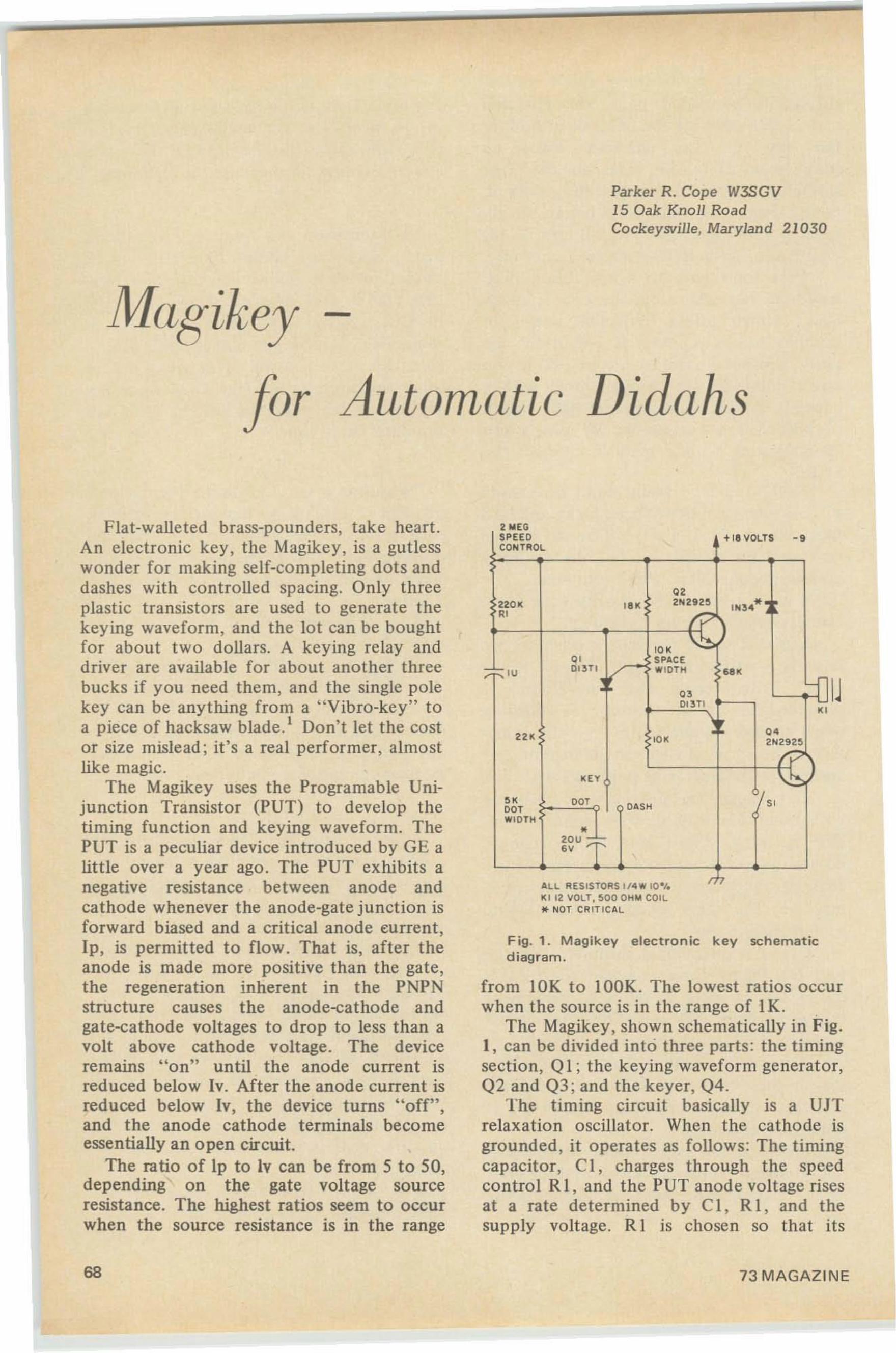
Parker R. Cope W3SGV15 Oak Knoll RoadCock eysville, Maryland 21030
-
or Automatic Didahs
2 NEG
j
SPEE D -+18 VOLTS -.CONT ROL
.,220 11 ,.. 210121125 I N3 4*.'
,., ~., SPACE,U O13T1 ./ WIDTH ...
., IDI 3Tl
"... , ••,., 2101292S
'"" "D.' OtlS H "00'WIDTH
•~e u ;.::::
• mALL RE SISTORS 1/4 '111 10 I.11 1 12 VOLT, SOD OHN COIL* NOT CRI TlC tlL
Fig. 1. M agikey electro n ic k ey schemat icdiagram.
from 10K to lOOK . The lowest ratios occurwhen the source is in the range of IK.
The Magikey, shown schematically in Fig.I , can be divided into three parts: the timingsection, Q 1; the keying waveform generator,Q2 and Q3 ; and the keyer, Q4.
The liming circuit basically is a UJTrelaxation oscillator. When the cathode isgrounded , it opera tes as fo llows: The timingcapacitor, C I, charges through the speedcontrol R 1, and the PUT anode voltage risesat a rate determined by C I , R I , and thesupply voltage. R I is chosen so that its
Flat-walleted brass-pou nders, take heart.An electronic key I the Magikey, is a gutlesswonder fo r making self-completing dots anddashes with controlled spacing. Only threeplastic transistors are used to generate thekeying waveform, and the lot can be boughtfor about two dollars. A keying relay anddriver are available for about another threebucks if you need them , and the single poleke y can be anything from a "Vibro-key" toa piece of hacksaw blade .' Don't let the costor size mislead ; it's a real performer, almostlike magic.
The Magikey uses the Prograrnable Unijunction Transistor (PUT) to develop thetiming function and keying waveform. ThePUT is a peculiar device introduced by GE alittle over a year ago . The PUT exhibits anegative resistance between anode andcathode whenever the anode-gate junction isforward biased and a critical anode eurrent ,Ip, is permitted to flow. That is, after theanode is made more positive than the gate,the regeneration inherent in the PNPNstructure cause s the anode-cathode andgate-cathode voltages to drop to less than avolt above cathode voltage. The deviceremains "on" until the anode current isreduced below Iv. After the anode current isreduced below Iv, the device turns Hoff",and the anode cathode terminals becomeessentially an open circuit.
The ratio of Ip to Iv can be from 5 to 50,depending on the gate voltage sourceresistance. The highest ratios seem to occurwhen the source resistance is in the range
68 73 MAGAZINE
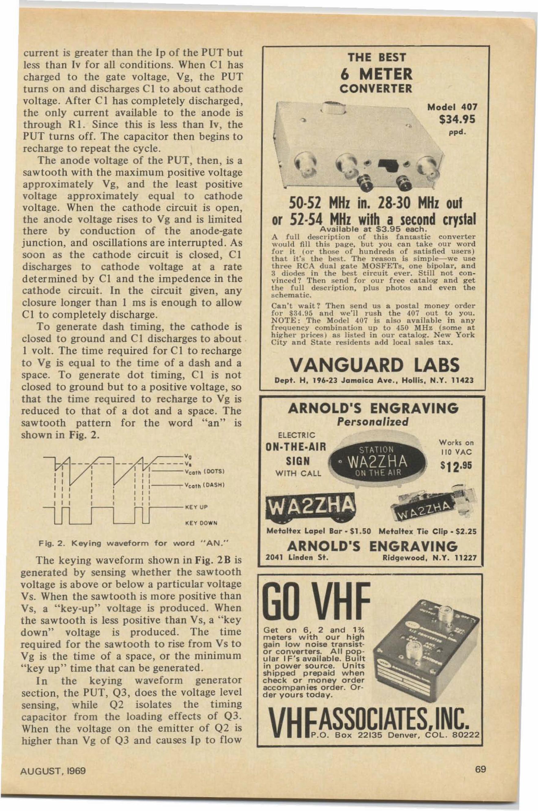
Works on11 0 VAC
$12,95
Model 407
$34.95ppd.
••
THE BEST
6 METERCONVERTER
•
Meta ltex Lapel Bar · $1.50 Metoltex Tie Clip. $2 .25
ELECTRiC
ON·THE·AIRSIGN
WITH CAll
ARNOLD'S ENGRAVINGPersonalized
50-52 MHz in, 28-30 MHz outor 52·54 MHz with a second crystal
Available at $3.95 each.A f u ll description of this f antastic conve rt erwou ld fill t h ill pag e, bu t you ca n t ake our wo rdfor it ( 0 1" t hose of h undreds of s at is fied users )t hat it's t he best. The rea son is s im ple-c-we usethree RCA dua l g ete l\.f OSFETs, o ne b ipolar, and3 diodes in t he best circu it ever. Still n ot con v inced ? Then se n d f or O U I" f r ee cat.alog- a n d getthe full description, plus photos lind - even thesc he ma t ic.Ca n 't wa it? T hen sen d U II a postal money orderfo r $34.95 a n d we'l! rus h t he 407 out t o you.N OTE : The Model 407 is a lso a vailable in an yI'requency comb inatio n up to 450 MH z (some athigher prieesj a s li sted in our cataloe. Ne w YorkCity and State r esi de n ts add loca l sa les t ax.
Dept . H, 196·23 Jama ica Ave. , Hollis, N.Y. 11423VANGUARD LABS
KEY DOWN
-----'._ __ ___ __ _ _ _ _ v.
: I : v(Ql lllOOTSI
, , ,----I 1 I Vea l ll {DAS H), , ,, , ,, , '- - - KE Y UP
----l1lJ
, ,r r, ,r ,r , ,
LIl_
current is greater than the Ip of the PUT butless than Iv for all conditions. When C I hascharged to the gate voltage, Vg, the PUTturns on and discharges C1 to about cathodevoltage . After C I has completely discharged ,the only current available to the anode isthrough Rl. Since this is less than lv, thePUT turns off. The capacitor then begins torecharge to repeat the cycle.
The anode voltage of the PUT, then , is asawtooth with the maximum positive voltageapproximately Vg, and the least positivevoltage approximately equal to cathodevoltage. When the cathode circuit is open,the anode voltage rises to Vg and is limitedthere by conduction of the anode-gatejunction, and oscillations are interrupted. Assoon as the cathode circuit is closed, C 1discharges to cathode voltage at a ratedetermined by Cl and the impedence in thecathode circuit. In the circuit given, anyclosure longer than I ms is enough to allowCI to completely discharge .
To generate dash timing, the cathode isclosed to ground and C I discharges to aboutI volt. The time required for CI to rechargeto Vg is equal to the time of a dash and aspace. To generate dot timing, CI is notclosed to ground but to a positive voltage, sothat the time required to recharge to Vg isreduced to that of a dot and a space. Thesawtoo th pattern for the word " an " isshown in Fig. 2.
Fig . 2 . Keying w aveform for word " A N ."
The keying waveform shown in Fig. 2B isgenerated by sensing whether the sawtoo thvoltage is above or below a particular voltageVs. When the sawtooth is more positive thanVs, a " key-up" voltage is produced. Whenthe sawtooth is less positive than Vs, a "keydown" voltage is produced . The timerequired for the sawtooth to rise from Vs toVg is the time of a space, or the minimum"key up" time that can be generated.
I n the keying waveform generatorsect io n, the PUT, 03, does the voltage levelsensing, while 02 isolates the timingcapacitor from the loading effects of 03.When the voltage on the emitter of 02 ishigher than Vg of 03 and cau ses Ip to flow
ARNOLD'S ENGRAVING2041 Linden St . Ridg ewood , N.Y. 11227
Get on 6, 2 a nd 1 %meters w it h our h ighgain low n oise transistor converters. All pOP.'u la r I F ' s availab le. BUiltin power sou rce. Unit sshipped p repaid whencheck or money o rderaccompanies order. Order yours today.
AUGUST. 1969 69
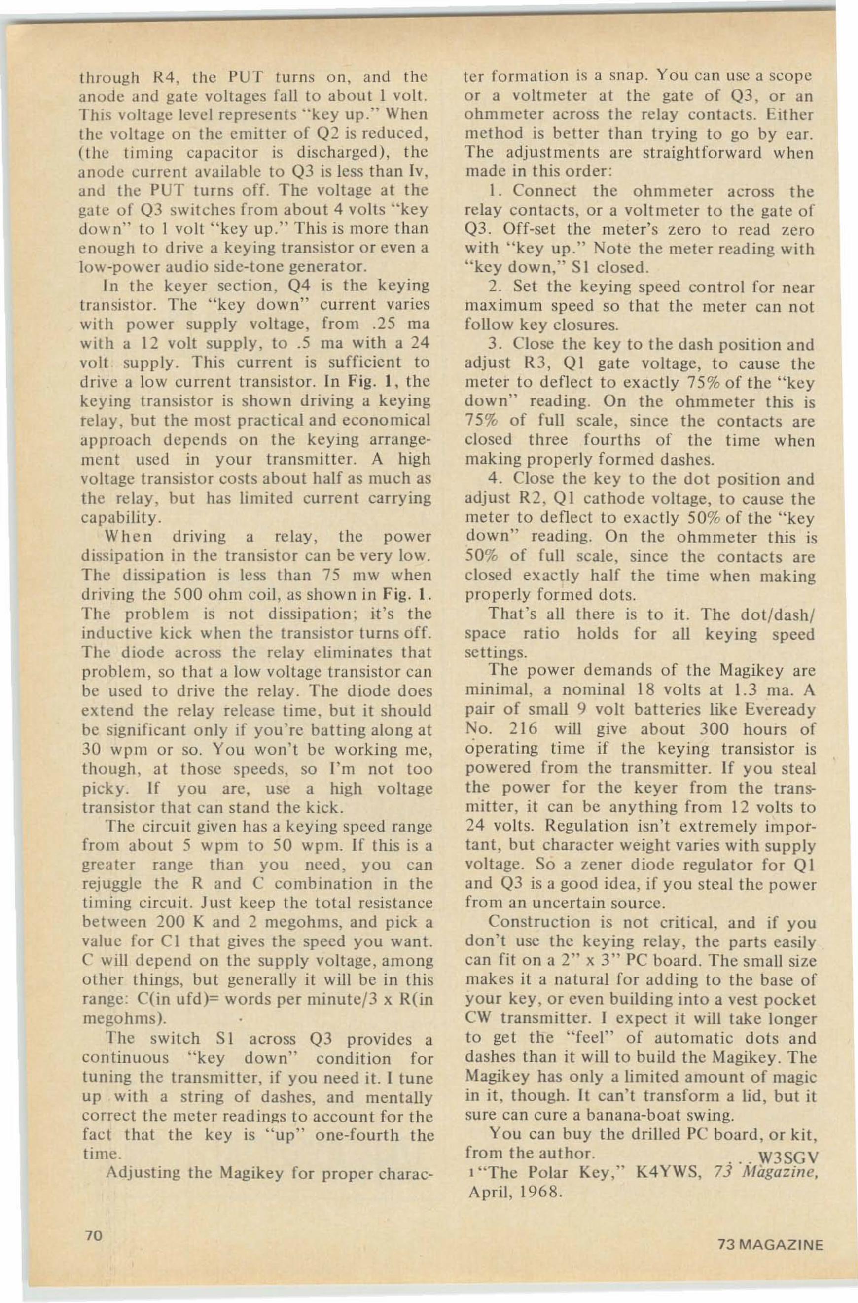
th rough R4, the PUT turns on, an d theanode and gate voltages fa ll to about I volt.This voltage level represent s "key up." Whenthe voltage on the emitte r of Q2 is reduced,(the t iming capaci tor is discharged), theanode curre nt available to Q3 is less than Iv,and the PUT turns off. The voltage at thegate of Q3 swi tches from about 4 volts " keydown" to 1 volt " key up. " This is more thane nough to drive a key ing transistor or even alow-power audio side-tone gene rator.
In t he keyer sec t ion, Q4 is the keyingtransistor. The " key down" current varieswith power supply voltage , from .25 rnawith a 12 volt supply , to .5 ma with a 24volt supp ly. This curre nt is sufficien t todrive a low curre nt transistor. In fig , I, thekeying transisto r is show n driving a keyingrelay , but the most prac tical and economicalapproach depends on the keying arrangement used in your t ransmitt er. A highvoltage transisto r costs about half as mu ch asthe relay , but has limited curre nt carryingcapability.
Wh en driving a relay, the powerdissipation in the transistor can be very low.The dissipat ion is less th an 75 mw whendriving the 500 ohm co il, as show n in Fig. I .The prob lem is not d issipat ion : it's theinduct ive kick when the transistor turns off.The diode across the relay eli minates thatproblem, so that a low voltage transistor canbe used to drive the relay. The diode doesexte nd the relay release time, but it shouldbe signifi cant only if you' re batti ng alo ng at30 wp m or so. You won 't be working me,though, at those speed s, so I'm not toopicky. If you arc, use a high voltagetransistor that can sta nd the kick .
The circuit given has a keying speed rangefrom about 5 wp m to 50 wpm. If this is agreater range than you need , you canrejugglc the Rand C combinatio n in thetimi ng circuit. Just keep the total resista ncebetwee n 200 K and 2 megohms, and pick avalue for Cl that gives the speed you wa nt.C will depe nd on the supply vo ltage, amongothe r things, but generally it will be in thisrange : CO n ufd)= words per minute/3 x ROnmegohms). .
The switch S 1 across Q3 provides acon tinuous "key down" condition fortu ning the t ransmitte r, if you nee d it. I tuneup with a st ring of dashes, and mentallycorrect the meter read ings to account for thefact that the key is " up" o ne- fo urt h thet ime.
Adjusting the Magikey fo r prope r cha rac-
70
ter fo rmatio n is a sna p. You can usc a sco peo r a voltmeter at the gate of Q3, o r ano hmmeter across the relay co ntac ts. Eithermethod is bett er than trying to go by car.The adju stments arc st raightfo rward whenmade in this order :
I . Connect the ohmmete r across therelay contacts, or a voltm eter to the gate ofQ3. Off-set the meter's zero to read zerowith "key up ." Note the meter reading with"key down ," S I closed .
2. Set the keying speed co ntro l for nearmaximum speed so that the met er can notfollow key closures.
3 . Close the key to the dash position andadjust R3, 01 gate voltage, to cause themeter to deflect to exactly 75% of the "keydown" reading. On the ohmmeter this is75 % of full scale, since the contacts areclosed three fourths of the time whenmaking properly fo rmed dashes.
4. Close the key to th e dot position andadjust R2, 0 I cathode voltage, to cause themeter to deflect to exac t ly 50% of the " keydown" reading. On the ohmmete r this is50% of fu ll scale, since the contac ts areclosed exactly half the time when makingproperly formed dots.
That 's " II there is to it. The dot/dash /space ratio holds for all keying speedsett ings.
The power demands of the Magikcy areminimal , a nominal 18 volts at 1.3 rna. Apair of small 9 volt batteries like Everead yNo. 2 16 will give about 300 hours ofoperating time if the keying transistor ispowered from the transmitter. If you stealthe power for the keyer from the transmitter, it can be anything from 12 volts to24 volts. Regulation isn't extremely important , but cha rac ter weight varies with supplyvoltage. So a zener diode regulator for Q Iand Q3 is a good idea, if you steal the powerfrom an uncertain so urce.
Const ruc t ion is not critical, and if youdon 't usc the keying rela y, the parts easilycan fit on a 2" x 3" PC board . The small sizemakes it a natural for adding to the base ofyour key, o r even building int o a vest pocketCW transmitter. I expect it will take longerto get the "feel" of automatic dots anddashes than it will to build the Magikey . TheMagikey has only a limited amou nt of magicin it , though. It can' t transform a lid, but itsure can cure a banana-boat swing.
You can buy the drilled PC board, o r kit ,from the author. . . . W3SGV' ''The Polar Key," K4YWS, 73 Magazine,April , 1968.
73 MAGAZINE
,
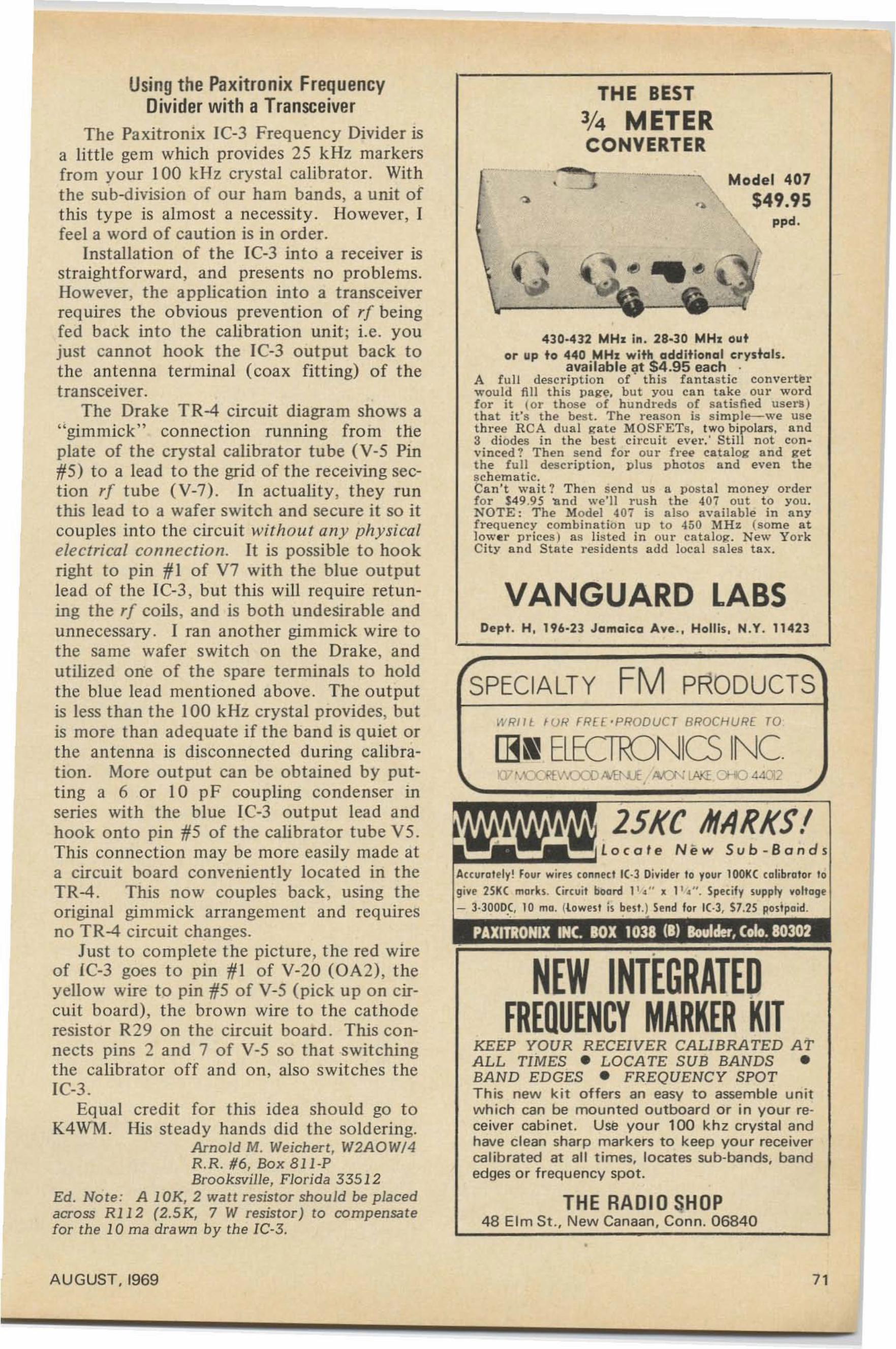
WR lIl ' UH FREe 'PRODUCT BROCHU R[ TO.
Model 407
$49.95ppd.
THE BEST
3J4 METERCONVERTER..,. --~
THE RADIO SHOP48 Elm St., New Ca naan, Con n. 06840
PAXITRONIX INC. lOX 1031 (I) Boulder, Colo. 10302
NEW INTEGRATEDFREQUENCY MARKER KIT
KEEP YOUR RECE1VER CAL1BRATED ATALL T1MES • L OCA TE SUB BANDS •BAN D ED GES • FREQUENCY SPOTTh is new kit o ffe rs an easy to assemble u nitw hich can be mou nted outboard or in your reoce iver cab inet . Use yo ur 100 k hz crystal a ndhave clean sharp markers to keep your receivercalib rated at all times, lo cates sub-bands, bandedges o r frequency spot.
,
Dept. H, 196-23 Jamaica Ave. , Hollis, N.Y. 11423
[BN ELECllDNICS INC(V t.-'CO'EV.cx::o M I'U, AoO'ILAiI 0-«) 4
VANGUARD LABS
4]0·432 MHz in. 28·]0 MHz outor up to 440 MHz with additional erys+als.
available at $4.95 each .A full description of' thi s fantastic converterwould fill this page. but you can ta ke our wordf or it lor those of hundreds of sa t is fi ed user s )that it's the best. The reaso n is sirnple-c-we uset hree R CA dual zate MOS F ETs, two bipolars , a nd3 diodes in the best circuit ever. ' Still not convinced ? Then send for our fret' catalog and getthe full description, plus photos and even theschem a t ic.Can't wait? Then send us a postal m oney orderfor $49.95 'and we'll rush the 407 ou t to you .NOTE : The Model 407' is a lso available in anyfrequency combination u p to -150 ~I Hz (some atlower prices ) a s li sted in ou r ca t a lcg. New YorkCity and State residents add local sa les tax.
SPECIALTY FM PRODUCTS
Accurll ttly! Four wire\ conntt! /C.) Divider to Yllur 1001« colibrotor 10
givt 251« morlu. (ircuit boord 1 1~ ". 11. ". Sptcify \Upply voltoge
- 3·3000(, 10 mo. (l owe\ t is but.) Send for 1( ·3, $7.25 postpaid.
Usi ng the Paxitronix FrequencyDivider with a Transceiver
The Paxitronix IC-3 Frequency Divider isa little gem which provides 25 kHz markersfrom your 100 kHz crystal calibrator. Withthe sub-division of our ham bands, a unit ofthis type is almost a necessity. However, Ifeel a word of caution is in order .
Installation of the IC-3 into a receiver isstraightfo rward, and presents no problems.However, the application into a transceiverrequires the obvious preve ntion of rf beingfed back into the calibration unit ; i.e. youjust cannot hook the IC-3 output back tothe antenna terminal (coax fitting) of thetransceiver.
The Drake TR-4 circuit diagram shows a"gimmick" connect ion running fro m theplate of the crystal calibrator tube (V-5 Pin1/5) to a lead t o the grid of the receiving section rf tube (V-7) . In ac tuality, they runthis lead to a wafer switch and secure it so itcouples into the circuit without any physicalelectrical connection. It is possible to hookright to pin 1/1 of V7 with t he blue outputlead of the IC-3 , but this will require retuning the rf coils, and is both undesirable andunnecessary. I Tan another gimmick wire tothe same wafer switch o n the Drake, andutilized one of the spare te rmina ls to holdthe blue lead mentioned above. T he out putis less than the 100 kllz crystal provides, butis more than adeq uate if the ba nd is quiet orthe ante nna is disconnected during calibration . More output can be obtained by putting a 6 or 10 pF coupling condenser inseries with the bl ue IC-3 output lead andhook onto pin 1/5 of the calibrator tube V5 .This connection may be more easily made ata circuit board conveniently located in t heTR-4 . This now couples back, using theo riginal gimmick arra nge ment and req uiresno TR-4 circuit changes.
Just to complete the picture, t he red wireof IC-3 goes t o pin 1/ 1 of V-20 (OA2), theyellow wire to pin 1/5 of V-5 (pick up on circui t board), the brown wire t o the ca thoderesisto r R29 on t he circuit board . This connects pins 2 and 7 of V-5 so that switchingthe calibrator off and on, also switches theIC-3.
Eq ua l credit fo r this idea should go toK4WM. His steady hands did t he soldering.
Arnold M . Weichert, W2AOW/4R.R. #6, Box 8 11-PBrooksville, Florida 33512
Ed. Note : A 10K, 2 watt resistor should be placedacross R112 (2.SK, 7 W resistor) to compensatefor the 10 rna drawn by the IC-3.
AU GUST, 1969 7 1
Steve M. Fried, K2PTSP.O. Box 212Owings Mills, MD 21117
}'M = Fun Maker
Most amateurs have heard of FM operation on the vhf ham bands but few areactually aware of "what's happening" andwhy the trend towards FM vhf, especiallywhy mobile FM. The purpose of this articleis to give some insight into an exciting phaseof amateur radio that seemingly has beenoverlooked by most. It is only within thepast two years that this phase of amateurradio has grown so large that ignoring itwould be cheating oneself of full use of hisamateur privileges.
The majority of FM activity is takingplace on six meters (called low-band) andtwo meters (called high-band). Activity canalso be found in lesser amounts on the 10 and3/4 meter bands. All opera tion is crystalcontrolled, both on receive and transmit .This eliminates receiver and transmittertuning and missed calls. Receivers becomemore sensitive since they don't have to bebroad-handed to cover the entire band. FMis noted for its quieting factor, which mostsay is better than AM. The audio level isconstant regardless of how strong or weakthe signal is. Two types of operation aregenerally in use. One is direct station-tostat ion (mobile to base, base to base, mobileto mobile, et c.), This direct communicationsis defined as simplex operation. The other isvia a repeater function . The use of a repeaterincreases the average mobile coverage to 30to 50 miles of so lid, noiseless, communications. The repeater and its basic operation isexplained later.
For those of us who must satisfy (justifymay be a be tter choice of word) the XYL onthe cost of a mobile installation and itsappearance, your best bet is FM . Most of theeq u ip ment available today is "trunkmount." That is - the transmitter/receivercombination mounts in the trunk of the carand out of sight (point No . I). All thatmounts in the front of the car is a small
72
control head (point No.2). The speaker canbe mounted up against the fire wall ifnecessary (point No.3) so all that is showingin the entire mobile installation is thecontrol head. The control head is so smallone would never notice it unless it wasbrought to his attention. The antenna also isa wife pleaser in that two and six meterwhips are smaller and less conspicuous than20 or 40 meter whip antennas.
FM has considerable potential for emergency communications, since operation issimplified and the performance is of commercial quality. If the above does not provea satisfactory argument for the XYL toallow a mobile installation, seriously consider the safety factor. If you or your wifeare out in the car late at night and shouldthe car break down all you have to do is pickup the mike and request help. Since everyone is crystal controlled on the same frequency you will be heard immediately. Thelarger (more populated) the city you're in,the more you need radio in the car forsafety's sake. It also follows that the largerthe city, the more FM radio amateurs thereare. The need for safety in a large city andthe response for help by FM you will receiveif plotted graphically would display similarcurves.
The FM mobile equipment is turned onwith the flip of the ignition key and is readyto monitor without tuning. The mobileequipment is always on the correct frequency. Ninety-eight percent of all equipment in use today is modified commercialFM two way radios that have been taken outof service from Police, Fire, Taxi, etc. Thebrand names most popular are Motorola,General Electric, and RCA. Most equipmentin use runs between 30 to 60 watts output.The amateur can find for sale (from anotherham) a complete FM set-up which includestransmitter/receiver (almost always on one
73 MAGAZINE
chassis), control head, speaker, microphone,and all power and control cables. The pricefor all this is only between $50 and $150depending usually up on the age of the unitin question. Tube sets using dynamotorsusually go complete, all tuned up withproper crystals and the aforementionedaccessories for around $50. A unit that isrelatively new (manufactured in the last sixyears or so) that has a transistorized powersupply complete with accessories would sellnear the $ 100 range. There are units now onthe market that run 80 watts out pu t and areco mpletely transistorized except for thefinal, co mplete with accessories that sellupwards of $350. But no matter what isfinally purchased (or horse traded) an FMinstallation is generally much less in costthan most amateur SSB mobile gear. Theprice range is generally the same regardlessof band chosen. The factor that varies theprice of a given unit would be law of supplyand demand and popularity of the unit inthat given area. If units are purchaseddirectly from a commercial outlet, conversion for ham use requires purchasingcommercial grade crystals and retuningvarious stages. Two meter gear requirespadding the front end of the receiver. UHFequipment (450 mhz) generally needs nomodification except for obtaining newcrystals and retuning. Additional output"sock" can be realized through the use of again antenna. Usually in regular amateurmobile service the vertical antenna gain atbest is unity (I). On two meters and higher again of +3 db can be had by using anantenna of greater than 1/4 wave length. Ontwo meters the 5/8 wave length antenna ispopular. The effective output of the transmitter is doubled by use of the gain antenna.
Throughout the country 146.94 mhz and52.525 mhz are found to be the most activefrequencies. These frequencies have beendesignated National Emergency and Callingfrequencies. National repeater frequenciesare : six meters 52.80 mhz input, 52.72output ; and on two meters: 146.34 mhzinput, 146.76 output. In some areas however, the repeater has output(s) on the mainfrequency (above).
Repeater stations have become quitepopular recently and are now in operation
AUGUST. 1969
throughout the country. These repeatersreceive on one frequency (i. e. 146.34 mhz)_and retransmit the received signal on anotherfrequency (i. e. 146.76 mhz) simultaneously.This gives mobile sta tions the advantage ofhigher power and an extremely highantenna. Mobile-to-mobile operation is extended greatly. Right now it is possible totravel across the country working through arepeater in one area and working throughanother repeater as you approach the nextarea. This is why standard repeater frequencies are a must.
The Maryland FM Association in theBaltimore area has an active repeater on thetwo meter band. An in-band six meterrepeater is scheduled for operation soon.The two meter repeater has an input of146.34 mhz and retransmits out on 146.76mhz. Due to my job I am in and out of thecar all day long. l ean 't spend the timetuning in stations, loading up the rig, callingCQ and hoping someone will be listening onthe freq uency I choose. Since most of mytravel is on the highway at 60 mph I'd ratherpay attention to the road and traffic. Withthe FM installation I just pick up themicrophone, hit the button and say."K2PTS mobile listening." Since my signalgoes through the repeater my mobile nowhas the extra sock of high power and anantenna at 200 feet, nine times out of ten Iwill get a reply.
The FM mode can not be compared toany other form of operation. Even so, FMstill holds a place for every type of interestin the amateur field. For the vhf DX manthe remote base stations and repeaters makeo rd i n ar y gr ound-wave co mmunicationsthrough use of these facilities comparable tothe best band openings. On the technicalside, the . builder and experimenter willbecome engrossed in the complexities oflong distance inter-connected repeaters,remote co ntrol, mobile telephone, etc.Those interested in net operation find thatthe FM mode fits in nicely with CivilDefense, RACES, MARS, AREC, etc. Forthe mobiler the advantages are infinite.
There is so much more to FM than justgetting a signal report. The resemblancebetween FM and any other mode is purelycoincidental. Why not give FM a try?
.. . K2PTS
73
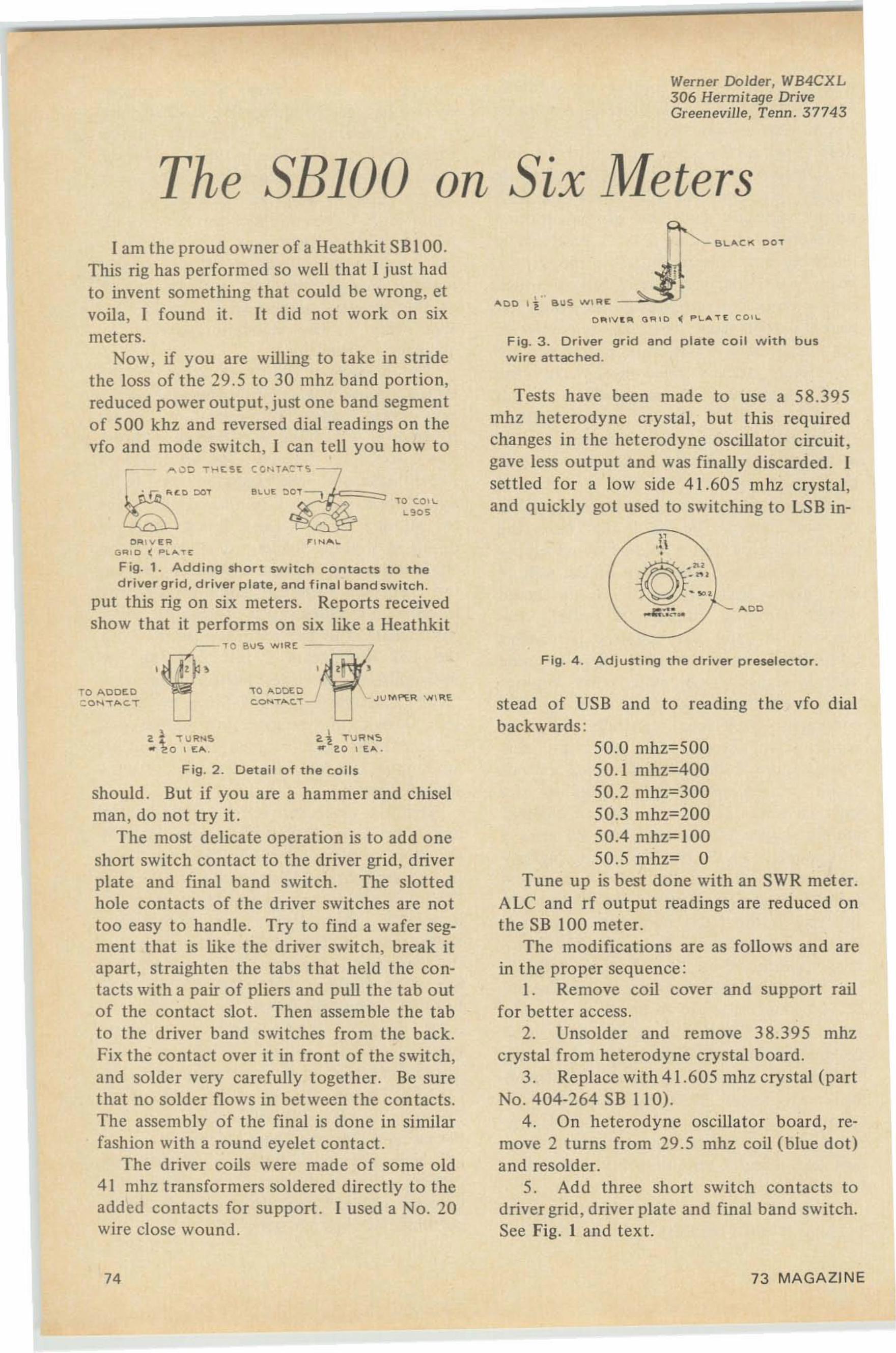
Werner Dolder, WB4CXL306 Hermitage DriveGreeneville, Tenn. 3774 3
The SE1DD on Six Meters
Fig. 1. Adding short switch co nt act s to thedriver grid, driver plate, and fina l band switch .
put this rig on six meters. Repo rts receivedshow that it performs on six like a Heathkit
~8l.""CI( DO T
F ig. 3 . Driver grid and p late coil w ith busw ire attached.
F ig . 4 . Adjusting the d river c resetecto r,
stead of USB and to reading the vfo dialbackwards:
50.0 mhz; 50050.1 mhz;40050.2 mhz;30050.3 mhz;20050.4 mhz» 10050 .5 mhz> 0
Tune up is best done with an SWR meter.ALC and rf out put readings are red uced onthe SB 100 meter.
The modificatio ns are as follows and arein the pro per sequence :
1. Remove coil cover and support railfor better access.
2. Unsolde r and remove 38.395 mhzcrystal from heterodyne crystal board.
3. Replace with 41.605 mhz crystal (partNo. 404-264 SB 11 0).
4. On heterodyne oscillator board , remove 2 turns from 29 .5 mhz coil (blue dot)and resolder.
5. Add three short switch contacts todriver grid, driver plate and final band switch.See Fig. I and text.
.... 0 01 1 " 8IJ S WIRE: -~
D Plll\1 . 1'l GOlIO ~ P LAT t C O I L
Tes ts have been made to use a 58.395mhz heterodyne crysta l, but this requiredchanges in the heterodyne oscillator circuit ,gave less output and was finally discarded . Iset tled for a low side 41. 605 mhz crystal,and quickly got used to switching to LSB in-
2.1 T\JR~'5... 2 0 I E. .... .
.. I N .......
-rc A OOE 0 .JC.ONT.....C.T
21 '! U RN'<o"" 2 0 1[;.... ,
O"'- \ V E RG""O ( ..~ " ,. t
F i9 . 2 . Detail of the coils
should . But if you are a ham mer and chiselman, do not try it.
The most delicate operation is to add o neshort switch contact to the driver grid, driverplate and final band switch. The slottedhole contacts of the driver switches are nottoo easy to handle. Try to find a wafer segment that is like the driver switch, break itapart, straighten the tabs t hat held the contacts with a pair of pliers and pull the tab outof the contact slo t. Then assemble t he ta bto the driver band switches from the back.Fix the contact over it in front of the switch,and solder very carefully together. Be surethat no solder flows in between the contac ts .The assembly of the fina l is done in similarfashion with a round eyelet contact.
The driver coils were made of some old41 mhz tra nsformers soldered direc tly to theadded contacts for support . I used a No. 20wire close wound .
I am the proud owner of a Heathkit SB 100.This rig has performed so well that I just hadto invent something that could be wrong, etvoila, I found it. It did not work on sixmeters.
Now , if you are willing to take in stridethe loss of the 29.5 to 30 mhz ba nd portion,reduced poweroutput,just one band segmentof 500 khz and reversed dial readings on thevfo and mode switch, I can te ll you how t o
TO AOOf.OCQ"IT ... C. T
74 73 MAGAZINE
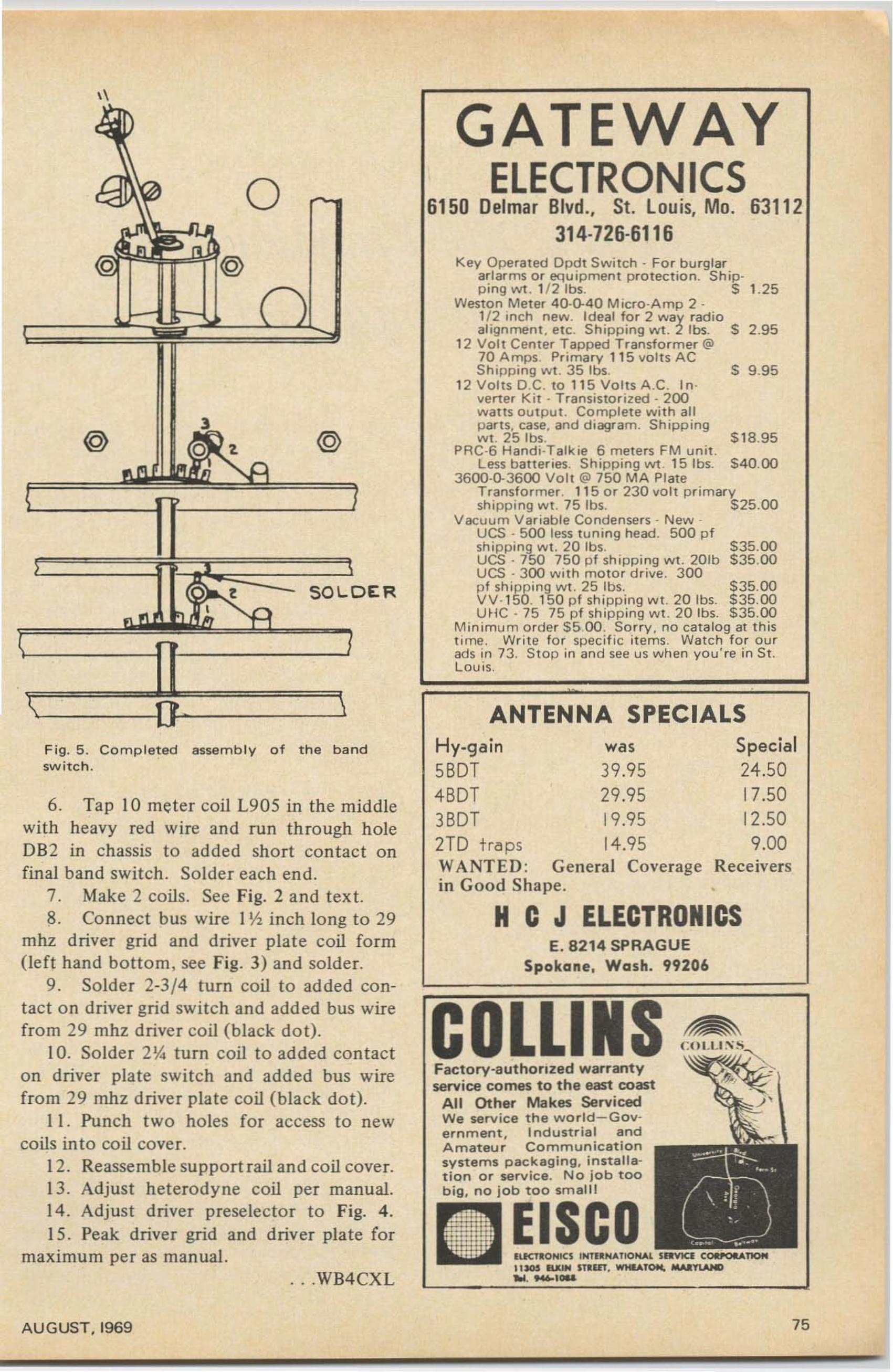
II
Key Opera ted Opdt S witch . Fo r bu rglara rlar m s o r equipment protectio n. S hip-ping wt . 1/ 2 1bs. S 1.25
Weston Meter 40 -0-40 Micro-Amp 2·1/2 inch new. Ideal for 2 way rad ioalign ment . e tc. Shipping 1M. 2 100. S 2.95
12 Volt Center Tapped Tr ansformer @70 Amps. Primary 11 5 vol ts ACShipping w t . 35 tbs . s 9.95
12 Volts D .C . to 115 Volts A.C . inverter K it· T ransistorized - 200watts ou tput . Complete wi t h allp ar ts, case, and diagram. Shipp ingw t . 25 tbs. $1 8 .9 5
PRC-6 Handi·Talkie 6 meters FM uni t .Less batteries. Shipping WI . 15 1bs. $ 40.00
3600·0-3600 Vol t @ 750 M A PlateTransfo rm er. 11 5 o r 230 vo l t pr imaryshipping w t. 75 Ibs. $25.00
Vacuum Var iable Condensers - N ew UCS - 500 less tu ning head. 500 p fshipping w t . 20 tbs. $35.00UCS· 750 750 pf sh ipp ing w t . 20 lb $35 .00UCS - 300 w i th moto r d r ive. 300p f sh ipping w t. 25 res. $ 35.00VV·150, 150 pf sh ipp ing wt . 20 tb s. $ 35.00U HC . 75 75 pf sh ipping w t . 20 Ibs. $35.00
Minimum orde r $ 5 ,00. So rry, no cat alo g at thi stime. Writ e fo r spec if ic it ems. Watch f o r ou rads in 73. Stop in and see us w hen you 're in St .L ouis,
GATEWAYELECTRONICS
6150 Delmar Blvd., St. Louis, Mo. 63112314-726-6116
@
SOLOE:R
o
@
ANTENNA SPECIALSSpecial24 .5017.5012.509.00
Receivers•
Hy.gain was560T 39.95460T 29.95360 T 19.952TD traps 14.95WANT ED : General Coveragein Good Shape.
IlICTl:ONICS 1HT1~NATlOMAL SRVJCI" C04lf'OIlATIONIlSGS IUUN STlut, WMlATOM. MAlT1.AHD~. "-101&
E. 8214 SPRAGUESpokane, Wash. 99206
HC J ELECTRONICS
Pectcrv-authonzed warrantyservice comes to the east coast
All Other Makes ServicedWe serv ice the w o r ld - G o vernment, Ind u stria l andA m at eu r C o mmunicationsystems packag in g, i n st a ll ation o r service. N o jo b t o obig, no jo b too small!
ElSea
COLLI NS
F ig. 5 . Completed assembly of the bandswitch .
. ..WB4CXL
6. Tap 10 meter coil L905 in the middlewith heavy red wire and run through holeDB2 in chassis to added short contact onfinal band switch . Solder each end.
7. Make 2 coils. See Fig. 2 and text.8. Connect bus wire I I> inch long to 29
mhz driver grid and driver plate coil form(left hand bottom, see Fig. 3) and solder.
9. Solder 2-3/4 turn coil to added contact on driver grid swi tch and add ed bus wirefrom 29 mhz driver coil (blac k do t) .
10. Solder 2 \4 turn coil to added contac ton driver plate switch and added bus wirefrom 29 mhz driver plate coil (black dot).
11 . Punch two holes for access to newcoils in to co il cover.
12. Reassemble support rail and coil cover.13. Adjust heterodyne coil per manual.14. Adjust driver preselector to Fig. 4.15. Peak driver grid and driver plate for
maximum per as manual.
AUG UST. 1969 75
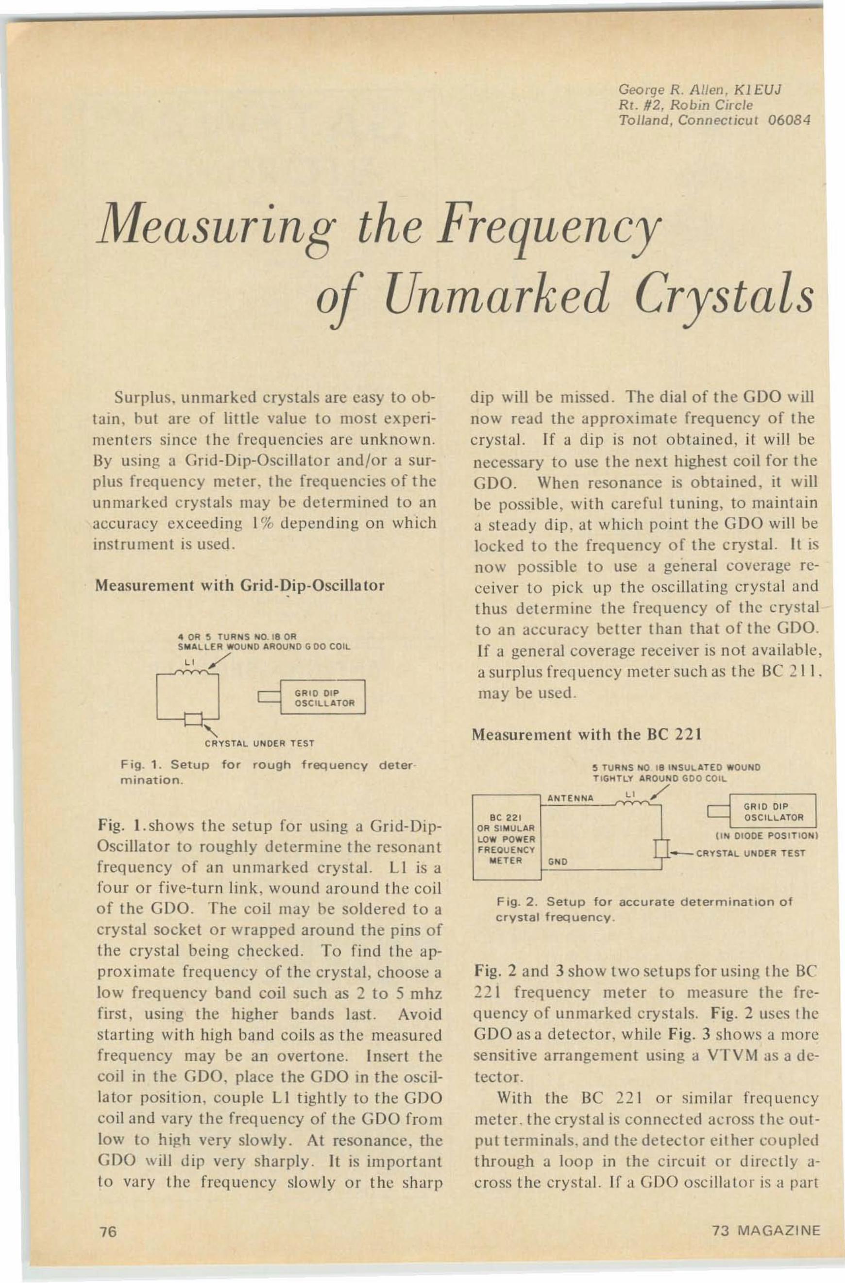
George R. A Jlen, Kl EUJRI . #2, Robin CircteTolland, Connecncu t 06084
Measuring the Frequency
o Unmarked Crystals
Surplus. unmarked crystals are easy to obtain. hut are of litt le value to most experiment ers since th e frequ en cies arc unknown .By using a Grid-Dip-Oscil lator and /or a surpills frequency meter. the frequenc ies of theun marked crys ta ls may he dete rmined to anacc uracy exceeding I% dependin g on whichinstrumen t is used .
Measurement with Grid-Dip-Oscillator
.. OR !l TUR"'S "'0 . 18 ORSMALLE R WOU"' O AROU"' O G 00 COIL
" /GRI D DIPOSCILLATOR
' ~,CRYST AL UNOE R TEST
dip will be missed . The dial of the GDO willnow read the approximate frequency of thecrys tal. If a d ip is not o btained. it will benecessary to usc the next highest coil for theGOO . When resonance is obtained. it willbe possible, with carefu l tu nin g, to mai ntaina steady dip . at which point t he GDO will helocked to the frequency of the crystal. II isnow possible to use a general coverage receiver to pick up t he osc illat ing crystal andt hus determi ne t he frequency of the crystalto an accuracy better than that of the GDO.H a general coverage receiver is not available,a surp lus frequency meter such as the Be 2 11.may be used .
Measurement with the Be 221
Fig. 1 . Setup for rough f req uency determination.
ANTE"'NA
e TUANS !'to 18 I"' SUL AT EO WOUNOTIGHTLY AROV"' O GOO COIL
" /GRIO DI P
Fig. 2 . Setup f o r accura te determination ofcrystal frequency .
Fig. 2 and 3 show two setu ps for usi ng the Be::!21 frequency meter to measure the frequen cy of unmarked crystals. Fig. 2 uses t heGDO as a de tec tor. while Fig. 3 shows a moresensit ive arrangement using a VTVM as a detec tor.
With the Be 22 1 or similar frequen cymeter. the crystal is connected ac ross the out put terminals. and the detector cit her coupledthrough a loop in the circuit or directly across the crys ta l. If a GDO osci llator is a part
Fig. l. shows the setup for using a Grid-DipOscillator to rough ly determine the resonantfreque ncy of an unmar ked crystal. LI is afour o r five-turn link , wound arou nd the coilof the GDO. The coil may he soldered to acrystal socke t or wrapped around the pins ofthe crysta l bei ng checked. To fi nd the approximate freq uency of the crystal , choose alow frequency band coil such as 2 to 5 mhzfirst , using the higher bands last. Avoidstarting with high band co ils as the measuredfrequency may be an overtone. Insert thecoil in the GOO. place the GOO in the oscillator posit ion, couple LI t ightly to the GDOco il and vary the frequen cy of the GOO fromlow to high very slowly . At resonance. theGOO will di p very sha rply . II is im portant10 vary th e frequ en cy slow ly or the sha rp
BC 221OA SI MULAALO W POWERFREOUEN CY
" ETE A G"'O
OS CILLATOA
II '" OIODE POSITlO Nl
76 73 MAGAZINE
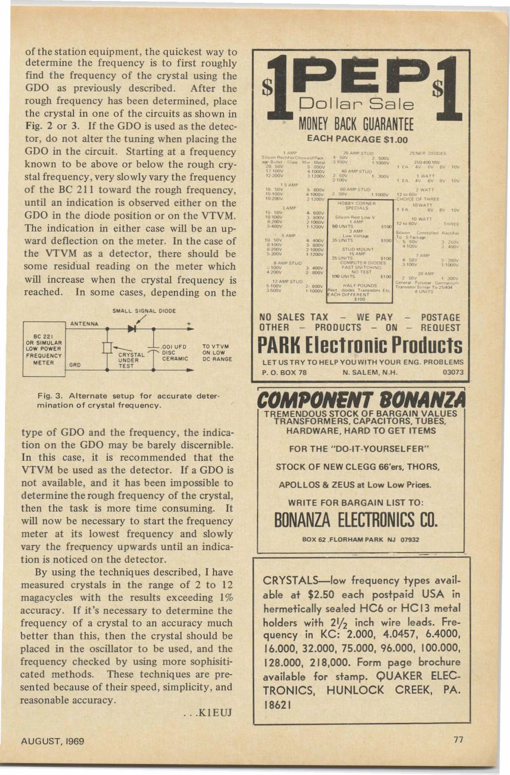
T"""
, " ,
10 ... . IT'1'0 60\'
S ' 0<>
S"o<M Coo"o"'" ",.ct.'".To SP.. ...'
SlO<' S ~• l OOV
$>I ..<>~ ....' l",", V1 A,,"P
50 U" ,TSl A"'P
l O" v",,_lS U"< lTS
l'Il AO.'p 5TUo Zf"''' 0'00., scv , ~,,,~ 1 l 000V 1">1).00 ·....', ,. " " av ,w
4QA"''' S TUIJ, ~, , ~, , W ATT1 ' OIlv , ,. " " ev ' W
OO"" PSTUO ~ ... . 11r ~ ,,- 11 , ,, 60\1
c-oecr 0' T.... U"088' COO " . .. 10 "ATTSI'.c"n5 , ,. sv ev 'w
sroc " Olftj T,~ A<OP
1!>U... ITS SI OlCOMPuTE R 0'0(1(5'AS t S'" Te.. ,.. !;.
" 0 niT'OO U" ITS
8 . " P STUOl 00v l AI)(\\;
• lOllv 1 8001I
J M'p
" sev10100va xov5 400V
S A Mp10 '>llv..ocve xov.-
'S AMP.. ~'S l 00v,,-
Dollar Sale,
MONEY BACK GUARANTEEEACH PACKAGE Sl.00
, A,·P5 .._ .."",_c"".ou'Po<'_ 8"'.., (,,_ '. " ~ >."'"
~o· !oOV 5 !IOOV1/ I!lOV 4 sooo vo soov acocv
of the stat ion equipment, the quickest way todetermine the freque ncy is to first roughlyfind the frequency of the crystal using theGDO as previously described. After t herough frequency has been determined, placethe cryst al in one of the circuits as shown inFig. 2 or 3. If the GDO is used as the detector, do not alter the tuning when placing theGDO in the circuit. St arting at a frequencyknown to be above or below the rough crystal frequency, very slowly vary the frequencyof t he Be 2 11 to ward the rough frequency,until an indication is observed eithe r on theGDO in the diode position or on the VTVM .The indication in either case will be an upward deflection on the meter. In the case ofthe VTVM as a detector, there should besome residual reading on the meter whichwill increase when the crystal frequency isreached . In so me cases, depending on the
POSTAGEREQUEST
LET US TR Y TO HELP Y OU WITH YOUR ENG. PROB LEMS
P. O. BOX 78 N. SALEM, N .H. 03073
NO SALES TAX WE PAYOTHER - PROOUCTS - ON -
PARK Electronic ProductsTO VTV M0 "1 LOWDC RANGE
A"ITENIIi... ~: +
ec 22 1OR SIMULAR T
J~TAL ::::::::: .00 1UF OLOW POWER ...
fR EQUE"ICYDISC
U"IOER CERAMICME T ER GR' TE ST
SMAL L SIGNAL DIODE
/
Fig. 3. A lte rnat e setup for a c curate determination of c ry st a l frequency.
type of GDO and the freq uency, the indication on the GDO may be barely discernible.In this case , it is recommended that theVTVM be used as the detector. If a GDO isnot available, and it has been impossible todetermine the rough frequency of the crystal,then the task is more time consuming. Itwill now be necessary to start the frequencymeter at it s lowest frequency and slowlyvary the frequency upwards until an indication is noticed on the detector.
By using the techniques described, I havemeasured cryst als in the range of 2 to 12magacycles with the results exceeding 1%accuracy. If it 's necessary to determine thefreq uency of a cryst al to an accuracy muchbetter than this, then the crystal should beplaced in the oscillator to be used , and thefrequency chec ked by using more sophisit icated methods. These techniques are presented because of their speed, simplicity, andreasonable accuracy.
...KI EUJ
'cOMPONENT BONANZATREMENDOUS STOCK OF BARGAIN VALUES
TRANSFORMERS, CAPACITORS. TUBES,HARDWARE. HARD TO GET ITEMS
FOR THE " DO·IT·YOURSElFER"
STOCK OF NEW CLEGG 66'.", THORS.
APOlLOS & ZEUS at low low Prices.
WRITE FOR BARGAIN LIST TO:
BONANZA ELECTRONICS CO.BO X 62 .FLOR HA M PARK NJ 07932
CRYSTALS-low frequency types available at $2.50 each postpaid USA inhermetically sea led HC6 or HC 13 metalholders with 21h inch wire leads. Frequency in KC: 2.000, 4.0457, 6.4000,16.000, 32.000, 75.000, 96.000, 100.000,128.000, 218,000. Form page brochureavailable for stamp. QUAKER ELEC·TRONICS, HUNLOCK CREEK, PA.18621
AUGUST, 1969 77
Getting Your Extra
Class License
Part VII - ReceicersSTAFF
Last mont h . we examined the nature o fnoise and also took a loo k at the various typesof de tec tors used in co mm unicat io ns receivers. In t his installment o f the Ext ra Classst udy course, let's st ick with receivers a littlelonger and find out som e of the more exo ticde tails .
In doing so. we 'll cover eight of the quest ions o n the FCC study list - a few more thanwe usually take care o f in a single section, butthese arc all rather closely related. The specif'ic questions involved arc :
I I . How does a squelch circuit operate?Draw a co mmonly used squelch circuit.
33. Ho w should a wave t rap be connectedto a receiving antenna circu it to attenuate aninterfering signal?
4 5. How do receivers for remote contro lo f o bjec ts and regular type co mmunicat io nsreceivers differ in basic operation?
46 . Ho w will a lo ng and a sho rt time constant AVC circuit affect recept io n?
51 . How do trimmer and padding capacitors affect receiver tuning"
59. Define the conversion efficie ncy of amixer tu be.
68 . What is the image-response of a receivcr? Ho w can it be reduced?
70. What effect will extending the lo wfrequen cy response to a signal have o n thedesign of an SS B receiver?
As always, we won 't attempt to answer anyo f these questions directly. If your only intcrest is in memorizing answers, there areother sources fo r that kind of in fo rmatio n.Inst ead , we' ll fra me a se t o f more generalq uest io ns which will cover all these and morebesides. and in the process of find ing the answers to that mo re general se t, get the answersto the study questions and all related q ue ries .
Th e majo r subject involved in all th eseq uestions is that of receiver desi gn and o peration. A logi cal sta rt ing point. then. would be
78
to ask "Wha t influences receiver design ?" but that 's just a little too big a question foro ur space. At least one book of more thanI ,400 pages has been written on that one,and the only way the subject was met in solittle space was to make generous use o f refe rences to ot he r volumes throughout!
So we will use a similar starting point, but3 more restricted question : "How does thepur pose of a receiver affect its design?",which will take care of question 4 5 amongothers ; then we'll try to de termine , " How dosignal characteristics influence receive r design?" and this should cover questions 46 and70.
Most o f today 's recei vers are superhe ts ,and superhets have so me special problem s.That's our third question -"What are someo f the special problems of superhets?" - andit will equip us to answer q uestions 51, 59and 68 o n the FCC list. Regardless of receiver type, in terference is always somethi ngwhich must be faced, and our fina l generalized question will be "How can we combatinterference?" That should take care of questions 11 and 33 amo ng o thers .
All set? Let 's move out.Ho w do es the purpose of a receiver aff ect
its design ? Radio receivers are designed formany purposes, and it appears obvious thatthe purpose of any individual receiver mustaffect its design rat he r st rongly. T he difference in design and performance between aninexpensive transisto r pocket por table BC setand a to p-grade SSB co mmunica t ions receiveris obvious-but each is adequate for its intended purpose, and nei ther has too much performance to meet that purpose.
The purposes to which receivers are putare so varied that we ca nnot list them all.Some of the more com mon are co mmunicati ons ( tha t's our own usc, mostl y ), entertainment (BC radio , FM, and T V), remote con-
AUGUST, 1969
t rol (RIC models a nd garage-door openers,for instance), and measurement (3 fieldstrength meter is, aft er all, merely a calibrated receiver).
The purpose of a receiver affects its designin many ways-but virtually all of the differences are in "performance parameters" suchas selectivity. sensitivity , stability o f tuning.distortion , and so forth. Regardless of thepurpose to which the receiver is to be put ,the absolute basics of the design and the principles upon which it operates remain prettymuch the sa me for all receivers.
After all, any receiver must perform thefunctions of isolating a desired signal fromthe many infesting the spectrum, buildingthat signal up to a usable level, and converting the modulation of the signal back intomeaningful o peratio n. This is just as true ofthe receiver in a garage-door o pener as it is ofthe sophisticated communications receiversused in manned space shots for capsule-toground communication; at this functionallevel there's no difference at all in basic operation between one receiver and another regardless o f the receiver's purpose.
However , so me purposes require more precise performance in certain parameters thando o thers. For instance, a garage-door o penerneed not be capable o f being tuned across theentire spectrum , or even across a wide band.It's going to be used with a single transmitter- or at least , a single group of transmittersall of which will be on the same frequency so the tuning o f its receiver need no t be easilyadjustable. On the o ther hand , a ham-bandcommunications receiver must be able to berapidiy and accurately tuned to any frequ ency in any of a number of widely-separatedamateur bands.
Similarly , a color-TV receiver must acceptsignals within a passband almost 6 mhz widewithout significant distortion of an y of them- but a communicatio ns receiver's passband,to be useful today, should not exceed 6 khz,which is three orders of magnitude smaller.
Differences of this sort, which are almostcompletely dictated by the purpose to whichthe receiver will be put , require co mpletelydifferent circuit designs to provide the required performance. Viewed at the circuitoperation level, then, the design is dictatedcompletely by the purpose of the receiver,and each different purpose requires a different set of basic o perating principles.
To illustrate, here are some of the keyperformance parameters for several differentreceiver purposes :
73 MAGAZINE
A co mmunications receiver may be either"al l-purpose" or "specialized;" a ham receiverwould be "all-purpose" in that it must be ableto receiv e many different types o f signalsfrom many different transmitters, while apolice mobile receiver is "specialized" in tha tit need receive only o ne type of signal fromone (or a very few) transmiller. Both . however, are used for communications.
An all-purpose co mmunications receiverneeds to be capable of easy tuning to any desired frequency, with excellent frequency stability once the desired frequency is reached.Selectivit y o f such a receiver should be adjustable , so that it may be set as narro w aspossible for any one desired signal, and theselectivity should be shar p in order to pickone signal o ut from adjacent-channel interference. The sensitivity of the receiver shouldbe maximum , so that it is not a limiting factor in performance. Distortion of the modulation should be small, but need not be reduced to the vanishing point. Audio po wer output need be only moderate. Fin ally , the receiver should be capable of receiving any typeof modulation used for communications :AM, FM, SSB, CW, FSK, and so o n.
A specializ ed co mmunications receiverneeds to meet essentially the same list of specifications, except for those requiring ease ofadjustment o f some factor which is absen t inthe specialized application. An example ofsuch an exception is the fact that a police receiver need no t be capable of receiving SSB,nor need it be tunable in most cases.
An entertainment receiver may be a BCBaudio receiver, an FM audio receiver, or a TVreceiver, and the parameters for each o f thesethree are different.
A BCB audio receiver need cover o nly thelimited frequency range of the broadcastband, with sensitivity adequate for receptionof local stations. Cost should be minimizedin the design and all unnecessary frills left out .Audio output should be mod erate, and dist ortion reasonably low. Good AVC action isa necessity, and the selectivity should presenta passband w ide en ough to permit receptionof music. The number of adjustments shouldbe reduced as far as possible ; in most caseso nly two co ntro ls- tuning and volume- areprovided .
An FM receiver requires excellent sensitivity , extremely low distortion, and sharpsided selectivity o ver a relatively wide passband. Automat ic freque ncy co ntrol is desirable since mistuning can crea te extremedistortion , and inclusion o f multiplex stereo
79
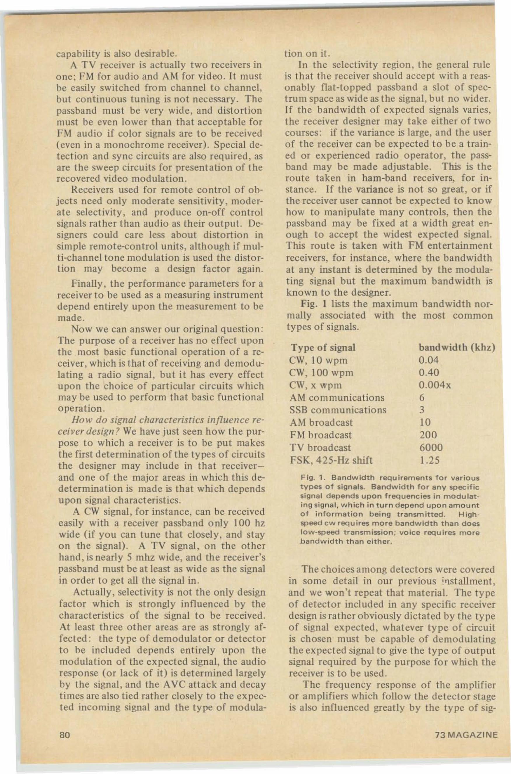
Fig. 1. Bandwidth requirements for varioustypes of signals. Bandwidth for any specificsignal depends upon frequencies in mocutet ing signal. which in turn depend upon amountof information being transmitted . High ·speed cw requires more bandwidth than doestow-speed transmission ; voice requires more.bandwidth than either.
The choices among detectors were coveredin some detail in our previous installment,and we won't repeat that material. The typeof detector included in any specific receiverdesign is rather obviously dictated by the typeof signal expected, whatever type of circuitis chosen must be capable of demodulatingthe expected signal to give the type of outputsignal required by the purpose for which thereceiver is to be used.
The frequency response of the amplifieror amplifiers which follow the detector stageis also influenced greatly by the type of sig-
tion on it.In the selectivity region , the general rule
is that the receiver should accept with a reasonably flat-topped passband a slot of spectrum space as wide as the signal, but no wider.If the bandwidth of expected signals varies,the receiver designer may take either of twocourses: if the variance is large, and the userof the receiver can be expected to be a trained or experienced radio operator, the passband may be made adjustable. This is theroute taken in ham-band receivers, for instance. If the variance is not so great, or ifthe receiver user cannot be expected to knowhow to manipulate many controls, then thepassband may be fixed at a width great enough to accept the widest expected signal.This route is taken with FM entertainmentreceivers, for instance, where the bandwidthat any instant is determined by the modulating signal but the maximum bandwidth isknown to the designer.
Fig. I lists the maximum bandwidth normally associated with the most commontypes of signals.
capability is also desirable.A TV receiver is actually two receivers in
one; FM for audio and AM for video. It mustbe easily switched from channel to channel,but continuous tuning is not necessary. Thepassband must be very wide, and distortionmust be even lower than that acceptable forFM audio if color signals arc to be received(even in a monochrome receiver). Special detection and sync circuits are also required, asare the sweep circuits for presentation of therecovered video modulation .
Receivers used for remote control of objects need only moderate sensitivity, moderate selectivity, and produce on-off controlsignals rather than audio as their output. Designers could care less about distortion insimple remote-control units , although if multi-channel tone modulation is used the distortion may become a design factor again.
Finally , the performance parameters for areceiver to be used as a measuring instrumentdepend entirely upon the measurement to bemade.
Now we can answer our original question :The purpose of a receiver has no effect uponthe most basic functional operation of a receiver, which is that of receiving and demodulating a radio signal, but it has every effectupon the choice of particular circuits whichmay be used to perform that basic functionaloperation.
How do signal characteristics influence receiver design ? We have just seen how the purpose to which a receiver is to be put makesthe first determination of the types of circuitsthe designer may include in that receiverand one of the major areas in which this dedetermination is made is that which dependsupon signal characteristics.
A CW signal, for instance, can be receivedeasily with a receiver passband only 100 hzwide (if you can tune that closely, and stayon the signal). A TV signal, on the otherhand, is nearly 5 mhz wide, and the receiver'spassband must be at least as wide as the signalin order to get all the signal in.
Actually, selectivity is not the only designfactor which is strongly influenced by thecharacteristics of the signal to be received.At least three other areas are as strongly affected : the type of demodulator or detectorto be included depends entirely upon themodulation of the expected signal, the audioresponse (or lack of it) is determined largelyby the signal, and the AVC attack and decaytimes are also tied rather closely to the expected incoming signal and the type of modula-
Type of signalCW, 10 wpmCW, 100 wpmCW, x wpmAM communicationsSSB communicationsAM broadcastFM broadcastTV broadcastFSK, 425-Hz shift
bandwidth (khz)0.0400400.004x631020060001.25
80 73 MAGAZINE
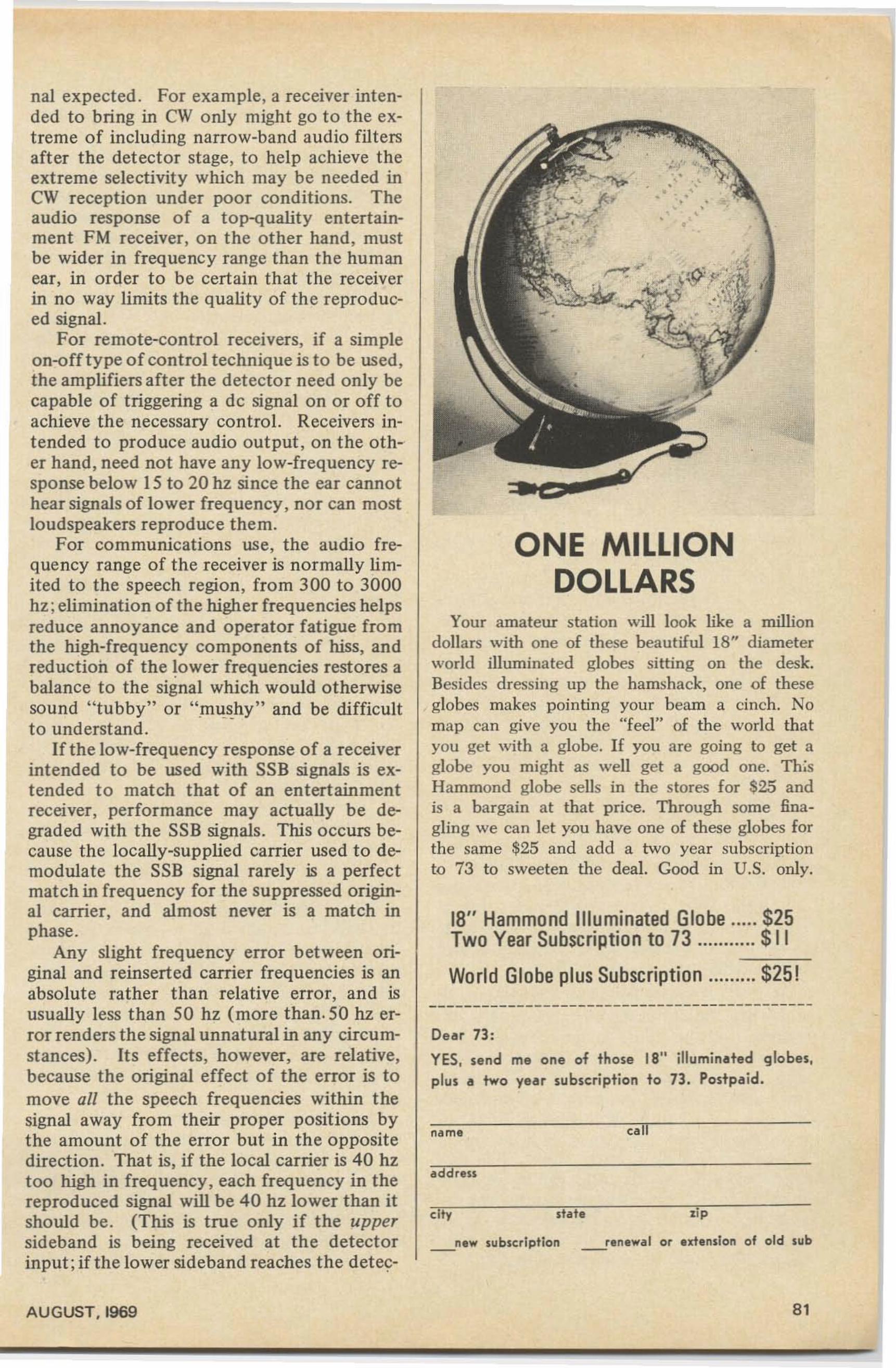
name
--------------------------------------------Dear 73:
YES, send me one of those 18" illuminated globes,plus a two year subscription to 13. Postpaid.
•••
'lip
,
•~
••••
•
renewal or extension of old sub
state
18" Hammond Illuminated Globe $25Two Year Subscription to 73 $11
World Globe plus Subscription $25!
Your amateur station will look like a milliondollars with one of these beautiful 18" diameterworld illuminated globes sitting on the desk.Besides dressing up the hamshack, one of theseglobes makes pointing your beam a cinch. Nomap can give you the "feel" of the world thatyou get with a globe. If you are going to get aglobe you might as well get a good one. 11I;sHammond globe sells in the stores for $25 andis a bargain at that price. Through some finagling we can let you have one of these globes forthe same $25 and add a two year subscriptionto 73 to sweeten the deal. Good in U.S. only.
ONE MILLIONDOLLARS
address
city
_new subscription
nal expected . For example, a receiver intended to bring in CW only might go to the extreme of including narrow-band audio filtersafter the detector stage, to help achieve theextreme selectivity which may be needed inCW reception under poor conditions. Theaudio response of a top-quality entertainment FM receiver, on the other hand, mustbe wider in frequency range than the humanear, in order to be certain that the receiverin no way limits the quality of the reproduced signal.
For remote-control receivers, if a simpleon-offtype of control technique is to be used,the amplifiers after the detector need only becapable of triggering a de signal on or off toachieve the necessary control. Receivers intended to produce audio output, on the other hand, need not have any low-frequency response below 15 to 20 hz since the ear cannothear signals of lower frequency, nor can mostloudspeakers reproduce them.
For communications use, the audio frequency range of the receiver is normally limited to the speech region, from 300 to 3000hz ; elimination of the higher frequencies helpsreduce annoyance and operator fatigue fromthe high-frequency components of hiss, andreduction of the lower frequencies restores abalance to the signal which would otherwisesound "tubby" or "mushy" and be difficult. ' .
to understand.If the low-frequency response of a receiver
intended to be used with SSB signals is extended to match that of an entertainmentreceiver, performance may actually be degraded with the SSB signals. This occurs because the locally-supplied carrier used to demodulate the SSB signal rarely is a perfectmatch in frequency for the suppressed original carrier, and almost never is a match inphase .
Any slight frequency error between original and reinserted carrier frequencies is anabsolute rather than relative error, and isusually less than 50 hz (more than. 50 hz error renders the signal unnatural in any circumstances). Its effects , however, are relative,because the original effect of the error is tomove all the speech frequencies within thesignal away from their proper positions bythe amount of the error but in the oppositedirection. That is, if the local carrier is 40 hztoo high in frequency, each frequency in thereproduced signal will be 40 hz lower than itshould be. (This is true only if the uppersideband is being received at the detectorinput; if the lower sideband reaches the detec-
AUGUST. 1969 81
tor, the error will be in the same directionand each frequency will be 40 hz too high.)
The difference between a 200o-hz component of speech and a I960-hz componentis so small as to pass unnoticed, and the difference between a 350·hz component and a310-hz component isn't particularlyobjectionable.
But the difference between an SO-hz component and a 40-hz component amounts to afull octave of pitch, and this is consideredobjectionable by almost everyone. Similarly,for an original component of 120-hz frequency the error would pull it down to So-hz,which is like the shift from the note of C tothe next lower G on the musical scale, andthat too isn't very good.
Thus the effects of any frequency errorbetween original and reinserted carrier aremost objectionable at the low end of thefrequency range. Preventing the audio stagesafter the detector from amplifying the lowfrequencies prevents these effects from beingobjectionable to the operator.
If for some reason a designer felt it necessary to include extended low-frequency response, he would then be faced with thenecessity of providing extreme frequencystability and a means for achieving nearperfect tuning accuracy. Since the low tonescontribute almost nothing to intelligibility ofthe signal, communications receivers simplyoperate with reduced audio response at thelow end and thereby simplify these designproblems.
Characteristics of the anticipated signalsaffect design of the AVC circuitry in a number of ways. The most extreme effect is thatof determining whether AVC will be included in the receiver, or left out. For some typesof signals, AVC need not be included, but inmost cases it is anyhow since it adds littleto the cost or complexity of the receiver andis frequently an operating advantage.
If AVC is to be included, the manner inwhich its control voltage is generated is determined by the signal to some degree. Forinstance, the FM discriminator does not provide an AVe control voltage; if such a detector is used a limiter stage must be included,and the AVC control voltage may be takenfrom this limiter stage where it is generatedas a by-product of limiting action. The FMratio detector, on the other hand, providesan AVC source as well as performing the demodulation of the signal. The envelope detectors used for AM detection usually providethe AVC voltage as well, but when SSB or
82
CW signals are being received, the AVC mustbe developed separately from the detectionprocess.
The function of the AVC circuit is tochange the receiver gain in accordance withthe signal strength; this prevents receiver overload as well as increasing the convenience ofoperation. Operation of an S-meter is not,contrary to some beliefs, the primary purposeof this circuit.
•When the gain is varied, especially in thecase of envelope detection of AM, the modulation may be affected. For instance, if a signal modulated with only a 100-hz sine wavewere being received, and the AVC were allowed to change receiver gain rapidly enough tofollow the 100-hz variation in envelope level,the modulation would be effectively wipedoff the signal!
To keep such events from occurring, thetime constants in the AVC circuit must bekept long enough so that receiver gain cannotchange during a single cycle of any expectedmodulating signal.
If the lowest frequency to be received is300 hz, the AVC time constants must not permit the receiver gain to change more rapidlythan 1/300 second. Because the gain changeis logrithmic with respect to voltage ratherthan being linear, and because time constantsbear only a relative relation to voltage levels,the time constants are usually kept longerthan 1/60 second . For communications use,a time-constant figure of 0.02 might be considered typical.
This is entirely too short a time constantfor entertainment reception, where frequencies as low as 20 hz may need to be reproduced. The time constants employed in thesecases are closer to I second.
The effect upon frequency response is notthe only factor involved in choice of AVCtime constant, however. One of the primaryreasons for putting in the AVC in the firstplace is to combat fading of the signal, andfading may occur at a rapid rate. The fadeof an aurora-reflected signal, for instance, occurs at a frequency well up in the audio range,and gives such a signal its characteristic buzzsaw whine.
And the time constants of the AVC circuitalso determine how rapidly the receiver willbe able to respond to a fade by increasingor decreasing gain. If the time constant is toolong, a given signal will appear to be fadingor fluctuating in level much more violentlythan if the time constant is short.
The choice of AVC time constant, then,
73 MAGAZINE
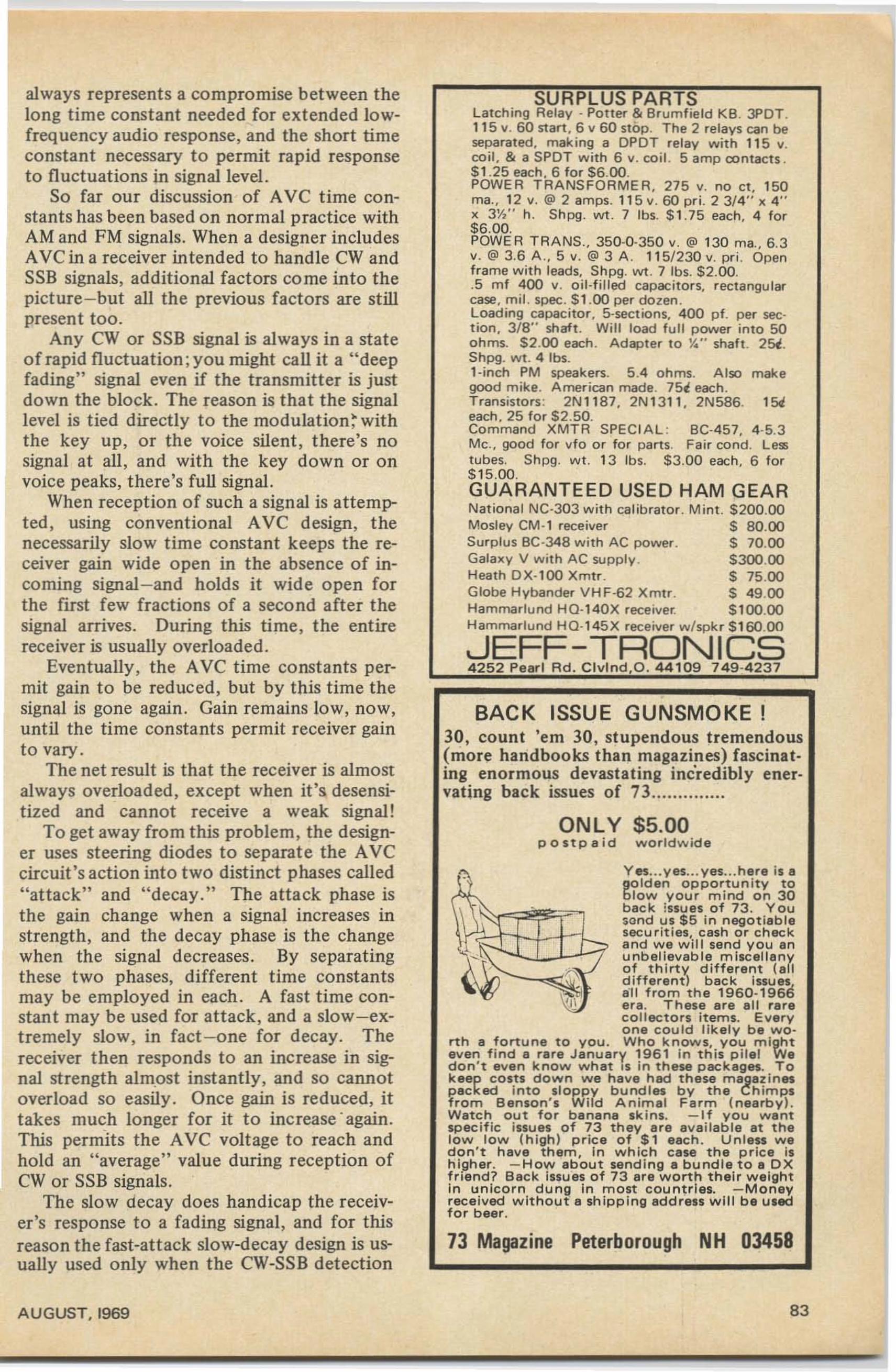
'II
always represents a compromise between thelong time constant needed for extended lowfrequency audio response, and the short timeconstant necessary t o permit rapid responseto fluctuations in signal level.
So far our discussion of AVe time constants has been based on normal practice withAM and FM signals. When a designer includesAVC in a receiver intended to handle CW andSSB signals, additional factors come into thepicture-but all the previous factors are stillpresent too.
Any CW or SSB signal is always in a stateof rapid flu ctuation ;you might call it a "deepfading" signal even if the transmitter is justdown the block. The reason is that the signallevel is tied directly to the modulation: withthe key up, or the voice silent, there's nosignal at all, and with the key down or onvoice peaks, there's full signal.
When reception of such a signal is attempted , using conventional AVe design, thenecessarily slow time constant keeps the receiver gain wide open in the absence of incoming signal-and holds it wide open forthe first few fractions of a seco nd after thesignal arrives. During this time , the entirereceiver is usually overloaded.
Eventually , the Ave time constants permit gain to be reduced, but by this time thesignal is gone again. Gain remains low, now,until the time constants permit receiver gainto vary.
The net result is that the receiver is almostalways overloaded, except when it's desensitized and cannot receive a weak signal !
To get away from this problem, the designer uses steering diodes to separat e the AVecirc uit's action into two distinct phases called" attac k" and "decay." The attack phase isthe gain change when a signal increases instrength, and the decay phase is the changewhen the signal decreases. By separatingthese two phases, different time constantsmay be employed in each. A fast time constant may be used for attack, and a slow-extremely slo w, in fact -one for decay. Thereceiver t hen responds to an increase in signal st rengt h almost instantly, and so cannotoverload so easily. Once gain is reduced, itt akes much longer for it to increase ' again.This permits the AVe voltage to reach andhold an " average" value during reception ofCW or SSB signals.
The slow uecay does handicap the receiver's response to a fading signal, and for thisreason the fast-attack slow-decay design is usually used only when the CW-SSB detection
AUGUST,I969
SURPLUS PARTSLatch ing Relay - Potter & Brumfie ld KB. JPDT.115 v. 60 start. 6 v 60 stop . The 2 relays can beseparated. making a DPDT relay wit h 115 v.co il. & a SPDT with 6 v. coi l. 5 amp co ntect s .$1.25 each. 6 for $6.00.POWER T RANSF ORMER. 275 v. no ct. 150ma., 12 v. @ 2 amps. 11 5 v . 60 pr i. 2 3/4" x 4 "x 3~" h. Sh pg. wt . 7 Ibs. $ 1.75 each. 4 for$6.00.POWER TRANS. , 350-0-350 v. @ 130 me.. 6 .3v, @ 3.6 A ., 5 v. @ 3 A . 11 5/230 v. pri . Openframe w it h lead s, Shpg, wt . 7 tbs. $2.00..5 m f 400 v. ci t.titled capacitors. rect angularcase, mil. spec . $ 1.00 per dozen.Loading capacitor. 5-sections. 400 pf. per section. 3/8" shaf t. Wi ll load full power into 50o hms. $2.00 each . Ad apte r to Y." shah. 25(.Shpg. wt . 4 Ibs.1-inch PM speakers. 5 .4 ohms. Also makegood mike. American made. 751! each,Transistors: 2N 1 18 7. 2N 1311, 2N586. 15«each. 25 for $2.50.Command XMT R SPEC IAL : BC-457, 4-5.3Me.• good for vfo o r for parts, Fair co nd o L esstubes. Shpg. w t. 13 Ib s. $ 3 .00 each , 6 f or$15.00.GUARANTEED USED HAM GEARNational NC·30 3 w ith calib rat o r . Mint. $ 200.00Mosley eM· 1 receiver $ 80.00Surplus BC-348 w ith AC power . $ 70 .00Galaxy V w it h AC supply . $300.00H eath OX· 100 Xmt r. $ 75.00Globe Hybander VH F-62 Xmtr. $ 49 .00Hammar lu nd HQ- 140X receiver, $ 100.00Hammar lund H Q-145 X receiver w /spk r $1 60.00
.JEFF-TRONICS4252 Pearl Rd. Clvlnd ,O . 44109 749-4237
BACK ISSUE GUNSMOKE !30, count 'em 30, stupendous tremendous(more handbooks than magazines) fascinating enormous devastating incredibly ener-vating back issues of 73 .
ONLY $5.00postpa id w o rldwid e
Y es.. .y es... yes.. .here is 011
golden opportunity toblow your m ind on 30back issu es of 73. Yousand us $5 in negotiablesecurities, c ash or ch ec kand we will send you anunbelievable miscellanyof thirty different (al ld ifferent) back issue~all from the 1960-1960era. These are all rareco llectors items. Everyone cou ld lik ely be wo
rth a fortune to y o u. Who k n ows. you mighteven find a rare January 1961 in this pilei Wedon't even k n o w what IS i n these packages. Tokeep costs down w e have had these magaz inespacked In t o sloppy bundles b y the Chimpsfrom Benson's Wild Anima l Farm ( n earb y).Watch out for banana skins. - I f you wantspecif ic issu es of 73 they are ava ilab le at thelow low (high ) price of $1 each. Unless wedon't have them, In which case the price ishigher. -How about sending oil bundle to oil OXfriend ? Back Issues of 73 are worth their weightin unicorn dung in most countrIes. - M o neyreceived without a shipping address will be usedfor beer.
73 Magazine Peterborough NH 03458
83
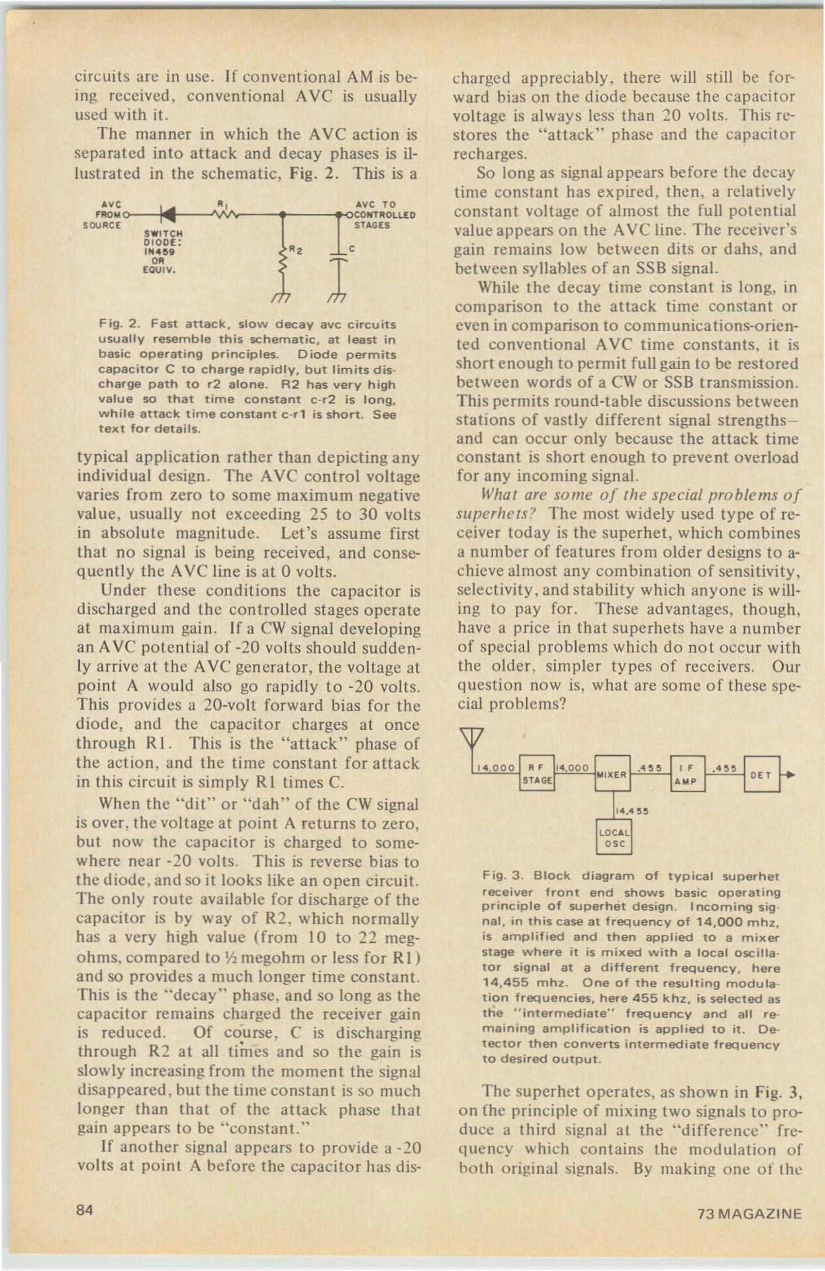
circuits arc in usc . If co nvent ional AM is being received, conventional Ave is usuallyused with it.
The manner in which the Ave action isseparated into attack and decay phases is illustrated in the schematic, Fig. 2. This is a
Fig . 2 . Fast attack. slow decay eve circu itsusually resemble this schematic, at least inbasic operating principles. Diode permitscapacitor C to charge rapidly, but limits discharge path to r2 alone. R2 has ve ry highvalue so that time constant c-r2 is long,while attack time co n st a n t c- r t is short. Seetext for details.
typical application rather than depicting anyindividual design . The AVe control voltagevaries from zero to so me maximum negativevalue, usually not exceeding 25 to 30 voltsin absolute magnitude. Let's assume fir stthat no signal is being received, and consequently the Ave line is at 0 volts.
Under these condit ions the capacitor isdischarged and the controlled stages operateat maximum gain . If a CW signal developingan Ave potential of -20 volts should suddenly arrive at the AVe generator, the voltage atpoint A would also go rapidly to -20 volts.This provides a 20-volt forward bias for thediode, and the capacitor charges at oncethrough R I . This is the "attack" phase ofthe action , and the time constant for atta ckin this circuit is simply R I times C.
When the "dit" o r " dah" of the ew signalis over . th e voltage at point A returns to zero,but now th e capacito r is charged to somewhere ncar -20 volts. This is reverse bias tothe diode , and so it looks like an o pen circuit.The only route available for discharge o f thecapacitor is by way of R2 , which normallyhas a very high value (fro m 10 to 22 megohms. co mpared to Yz megohm or less for R1)and so provides a much longer time constant.This is the "decay" phase, and so long as thecapacitor remains charged the receiver gainis reduced. Of course , C is discharging
•through R2 at all times and so the gain isslowly increasing from the moment the signaldisappeared , but the time co nstan t is so mu chlonger than that of the attack phase thatgain appears to be "constan t."
If another signal appears to provide a -20volts at point A before the capac ito r has dis-
SWITCH0100[;IH'U59
""[OUIv,
"
"
I
cha rged apprec iably, there will still be fo rward bias on the diode because the capacitorvoltage is always less than 20 volts. This resto res the "attack" phase and the cap acitorrecharges.
So long as signal appears before the decaytime co nsta nt has ex pired, then . a relativelyconstant volt age of almost the full poten t ialvalue appears on the AVC line . The receiver'sgain remains low between dits or dahs, andbetween syllables of an SSB signal.
While the decay time co nstan t is long, inco mpariso n to the attack time co nstan t oreven in co m parison to communications-o riented co nventional AVe time constants. it isshort en ough to permit full gain to be rest oredbetween words of a CW or SSB transmission.This permits round-table discussions betweenstations of vastly different signal strengths and can occur only because the attack timeconstant is sho rt enough to prevent overloadfor any incoming signal.
What are some of th e special prob lems ofsuperhets? The most widely used type of receiver today is the superhet , which combinesa number of features from old er designs to achieve almost any com bination of sensit ivity ,selectivity , and stabili ty which anyone is willing to pay for. These advantages, though ,have a price in that superhets have a numberof special problems which do not occur withthe older. simpler types of receivers. Ourquestion now is, what are some of these special problems?
\V14.000 R F 114.0 0 0 .455 " .4 5 5 1+STAGEl
frIl l:O:ER ,., ' "14.4 5 5
LOC AL
'"Fig. 3 . Block diagram of typical supe rhetreceiver front end shows basi c operatingprinciple of superhet design . Incoming sig ·nal, in this case at frequency of 14,000 mh z,is a m p lif ied and then ap plied to a m ix erstage w h e re it is mixed w it h a local oscillator signal at a different frequency. here14,455 mhz . O ne of t h e resulting rnod ura non frequencies, here 455 khz, is se lected asth e " in t e rm ed ia t e" frequency and a ll remaining ampli fi cat ion is applied to it. Detector then co nve rt s intermediate frequ e n c yto desired output .
The superhet o perates , as shown in Fig. 3,o n {he principle of mixing two signals to produce a th ird signal at the "difference' frequency which co ntains the modulation ofhoth origi nal signa ls. By making one o f the
84 73 MAGAZINE
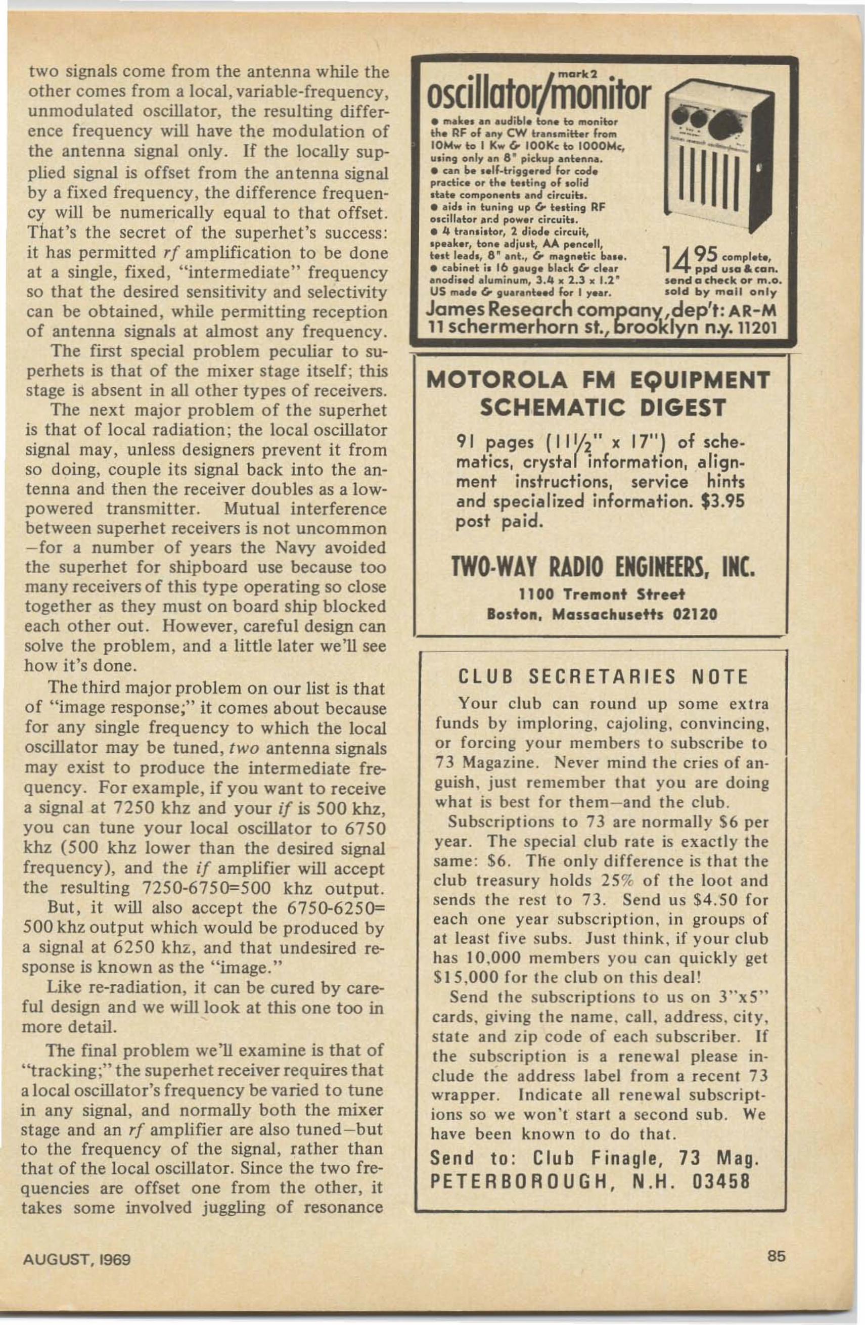
TWO·WAY RADIO ENGINEERS, INC.1100 Tremont Street
Boston. Massachusetts 02120
MOTOROLA FM EQUIPMENTSCHEMATIC DIGEST
91 pages (I 1Ih" x 17") of sehematics, crystar ·information. alignment instructions. service hintsand specialized information. $3.95post paid .
CLUB SECRETARIES NOTEYou r club can round up so me ex tra
fund s by imploring, cajoli ng, convincing,or fo rcing yo ur members to subscribe to73 Magazine. Never mind (he cries of anguish, just remember that yo u are doingwhat is best for them-and the club.
Subscriptions to 73 are normally $6 peryea r. The special club rat e is exactly thesame: S6. The only diffe rence is tha t theclub tr easury holds 2S% of the loot andsends the rest to 73 . Send us $4. 50 fo reach one year subscription, in groups ofat least five subs. Just thi nk, if your clubhas) 0,000 members yo u can quickl y get$15.000 fo r th e club on this deal!
Send the subscriptions to us on 3"xS"cards. giving the name. call, address, city.state and zip code of each subscriber. Ifthe subscription is a renewal please include the add ress label from a recent 73wrapper. Indicate all renewal subscriptions so we won' t sta rt a second sub. Wehave been known to do that.
Send to: Club Finagle, 73 Mag.PETERBOROUGH, N.H. 0345B
oscillafOl/monifor _.• m.I. udibl. to to mo.. ito, ftth e RF of , CW b ' mitt.r from :.~ .
.t.t. compo h . ...d c.rcu,h.• .id. i... tuning up (,. t • •ti ... , RFolcillator . r: d pow.r circ uit..• 4 ba....i_tor. 2 diod. circuit,. p••I..r, to ... . . djut , AA p....c.1It.tt I• •d_, 8 · . nt., (,. m.gn.tic b._.. 1495 compl.t.,• u binet il 16 , auge bl.ck (,. cl••r ppd uta Iocan•. ...odi_. d . Iuminum, 3.4 • 2.3 • 1.2 · ••nd 0 ch.ck or m .o.US m.d. (,. guaranteed for I , • • r. t old by moll only
James Research company',dep't: AR-M11 schermerhorn st., brookl n n.y.11201
two signals come from the antenna while theother comes from a local , variable-frequency,unmodulated oscillator, the resulting difference freq uency will have the modulation ofthe antenna signal only. If the locally supplied signal is offset fro m the an tenna signalby a fixed freq uency, the diffe rence frequency will be numerically equal to that offset.That's the secret of the superhet's success :it has permitted rf amplification to be doneat a single, fixed, "intermediate" frequencyso that the desired sensitivity and selectivitycan be obtained, while permitting receptionof antenna signals at almost any frequency .
The first special problem peculiar to superhets is that of the mixer stage itself ; thisstage is absent in all other types of receivers.
The next major problem of the superhetis that o f local radiation; the local oscillatorsignal may, unless designers prevent it fromso doing, couple its signal back into the antenna and then the receiver doubles as a lowpowered transmitter. Mutual interferencebetween superhet receivers is no t uncommon- for a number of years the Navy avoidedthe superhet for shipboard use because toomany receivers of this type operating so closetogether as they must on board ship blockedeach other out . However, careful design cansolve the problem, and a little later we'll seehow it's done.
The third major problem on ou r list is thatof "image response;" it comes about becausefor any single frequency to which the localoscillator may be tuned, t wo antenna signalsmay exist to produce t he in termediate frequency. For example, if you want to receivea signal at 7250 khz and your if is 500 khz,you can tune your local oscillator to 6750khz (500 khz lower than the desired signalfreque ncy), and the if amplifier will acceptthe resulting 7250-6750=500 khz output.
But , it will also accept the 6750-625 0=500 khz output which would be produced bya signal at 6250 khz, and that undesired response is known as the "image."
Like re-radiation, it can be cured by careful design and we will look at this one too inmore detail.
The final problem we'll examine is that of"tracking;" the superhet receiver requires thata local oscillator's frequency be varied to tunein any signal, and normally both the mixerstage and an rf amplifier are also tuned -butto the frequency of the signal, rather thanthat of the local oscillator. Since the two frequencies are offset one from the other, ittakes some involved juggling of resonance
AUG UST. 1969 85
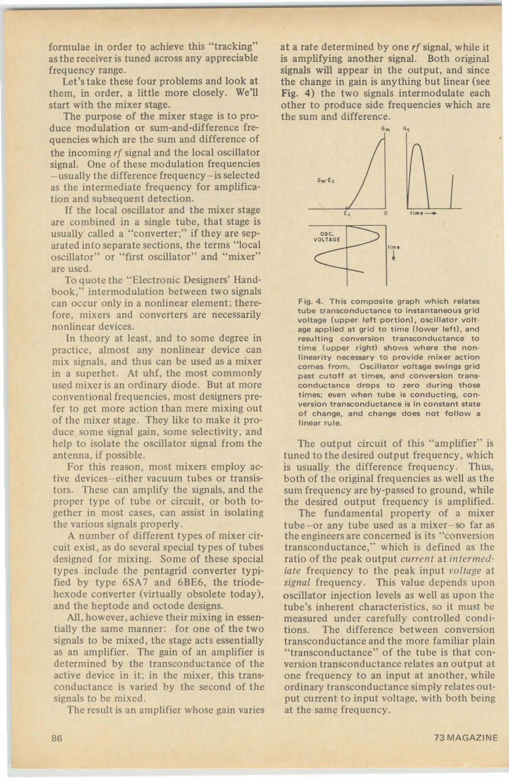
at a rate determined by one rf signal, while itis amplifying another signal. Both originalsignals will appear in the output, and sincethe change in gain is anything but linear (seeFig. 4) the two signals intermodulate eachother to produce side frequencies which arethe sum and difference.
Fig. 4. This c o m p o sit e graph which relatestube transconductance to instantaneous gridvoltage (upper left portion), oscillator voltage applied at grid to time {tower left}, andresulting conversion transconductance totime (upper right) shows where the nonlinearity necessary to prov ide mixer act io ncomes from . Osc illa t o r voltage swings gr idp ast cutoff at times. and conversion transco nd uct a nce drops to zero during thosetimes; even when tube is conducting. c o nversion transconductance is in constant stateof change, and change does not follow alinear rule.
•
u... _o
esc.VOLTAGE
G",-E c
c
The out put circuit of this "amplifier" istuned to the desired o utput frequency , whichis usually the difference frequency. Thus,both of the original frequencies as well as thesum frequen cy are by-passed to ground, whilethe desired out put frequency is amplified.
The fundamental property of a mixertube - or any tube used as a mixer- so far asthe engineers are concerned is its " conversiontran sconductance," which is defined as theratio of the peak output current at intermediate frequency to the peak input vo ltage atsignal frequency. This value depends uponoscillator injection levels as well as upon thetube's inherent characteristics, so it must bemeasured und er carefully cont rolled conditions. The difference between conversiontransconductance and the more familiar plain"transconductance" of the tube is that conversion transconductance relates an output atone frequency to an input at another. whileordinary transconductance simply relates output curre nt to input voltage, with both beingat the same frequency .
formulae in order to achieve this " t racking"as the receiver is tuned across any appreciablefrequency range.
Let's take these four problems and look atthem, in order , a little more closely. We'llstart with the mixer stage.
The purpose of the mixer st age is to produce modulation or sum-and-difference frequencies which are the sum and difference ofthe incoming rf signal and the local oscillatorsignal. One of these modulation frequencies- usually the difference frequen cy-is selectedas the intermediate frequency for amplification and subsequent detection.
If the local oscilla tor and the mixer stageare co mbined in a single tube, that stage isusually called a "converter;" if they are separated into separate sections, the terms "localoscillator" or "first oscillator" and " mixer"are used.
To quote the " Electronic Designers' Handbook," intermodulation be tween tw o signalscan occur only in a nonlinear element ; therefore, mixers and converters are necessarilynonlinear devices.
In theory at least , and t o some degree inpractice, almost any nonlinear device canmix signals, and thus can be used as a mixerin a superhet. At uhf, the most commonlyused mixer is an ordinary diode. But at moreco nventional frequencies , most designers prefer to get more action than mere mixing outo f the mixer stage. They like to make it produce, some signal gain, some select ivit y, andhelp to isolate the oscillator signal from theantenna, if possible.
Fo r this reason , most mixers employ active devices-either vacuum tubes or transistors. These can amplify the signals, and theproper ty pe of tube or circuit, or both together in most cases, can assist in isolatingthe various signa ls properly.
A number of diffe rent types of mixer circuit exist, as do several special types of tubesdesigned fo r mixing. Some of these specialtypes include the pentagrid converter typified by type 6SA 7 and 6BE6, the triodehexode converter (virtua lly obsolete today),and the heptode and octode designs.
All, however, achieve their mixing in essent ially the same manner : for one of the twosignals to be mixed, the stage acts essen tiallyas an amplifier. The gain of an amplifier isdetermined by the transconductance of theactive device in it : in the mixe r, this transconductance is varied by the second of t hesignals to be mixed .
The result is an amplifier whose gain varies
86 73 MAGAZINE
The term "conversion efficiency" is apparently unknown to professional receiverdesigners. At any rate, it is not mentionedin "Electronic Designers' Handbook," the"Radiotron Designer's Handbook," Terman's"Electronic and Radio Engineering," or BillOrr's "Radio Handbook." The only publication we could find which does mention thisphrase, in fact, is the ARRL Handbook! Theprofessionals in the field call this factor "mixer amplification" rather than "conversion efficiency"-but whatever the name used, it'sthe ratio of intermediate-frequency outputvoltage to signal-frequency input voltage, andyou can calculate it by multiplying the if loadimpedance in the mixer plate circuit by theconversion transcond uctance of the stage.
Aside from achievement of adequate stagegain-or "conversion efficiency"-the majorproblem presented by the mixer stage is thatof adequately isolating the local oscillatorand the input signal each from the other,while providing enough injection to permitproper mixing action. If isolation is insufficient, the oscillator may be "pulled" bystrong signals with a resulting frequency shift.In addition, the oscillator signal may be radiated to cause interference to other receivers,and performance will suffer due to circuitloading in the mixer and preceding stages.
Use of separate mixer and oscillator stageshelps in control of signal isolation, as doesthe use of specially designed mixer tubeswhich minimize interaction between theirtwo input circuits. When conventional tubesare found desirable, special circuitry may beused. See the previous installment of thisstudy course for one such circuit which usesa pair of triodes to provide almost completeisolation of oscillator and signal frequencieswhile achieving good mixing action over awide range of signal strengths and providingexceptional stage gain. For additional mixercircuits, referto any of the books listed at theend of this installment.
The second problem we'll examine is thatof preventing radiation from the local oscillator. This is tied up to some degree with themixer circuit, but is not confined to the mixer alone . Several other factors must also beconsidered.
For instance, the re-radiation problem isalways more severe when the mixer is connected directly to the antenna than when anr[amplifier comes between antenna and mixer. The oscillator signal is always present, tosome degree, in the mixer's grid circuit evenwhen the most isolating mixer possible is
AUGUST, 1969
ELECTRONICS10 ALICE ST. BINGHAMPTON. N.Y.
13904, AC 607 723 ·3111
• COPPER CLAD PC BOARDS, 6" X 36"CC both sides $2.16, 6" X 9 3/4" CCboth sides 60l'!, 7" X 11 3/4" Coneside 841'!, 5" X 7'/," CC both sides 40l'!,
• STUD MT SILICON RECTIFIERS 12amp, 50 PRV. pkg of 5 $1.00
• ELECTROLYTICCAPACITOR 1250 mfd180 vdc. 2" X 4%" 501'! ea.
• JUST BOUGHT OUT ORIGINAL CASEFOR CB RADIO. Includes mtg bracketfor mobile use & slide-in chassis. Holespre-punched for power transistor & power cord. May be used for mobile powersupplies, P.A. system or speaker box ormany other uses. Size' 3'/," H X 7" WX 8'/," D. Weight 3 Ibs. Original cost$9.95. Our price $1.95
MIN ORDER $5.00
Buy 73 binders and win the loveof a beautiful girl. Still only$3.00!
87
used. If this grid circuit is coupled directly toan antenna, that small oscillator signal mayescape . With the beller mixer designs theamount of oscillator signal which can escapethrough the grid circuit is small enough to bewithin legal limits- but an intervening r[ amplifier can reduce it still more , and will.
No number of intervening stages can prevent radiation , however, unless the local oscillator signal is rigidly confined within the receiver to the areas where it is necessary. Thismeans that the oscillator circuit should beshielded as completely as possible, and thatall leads to and from this circuit be eithershielded or filtered , to make certain that nosignal escapes to be coupled accidentally toany part of the antenna or power-line.
Re-radiation of the local oscillator signalcan have serio us co nsequences. Not long ago,radiation from garage-door openers was foundto be interfering with the radio navigationequipment on jetliners in the crowded LosAngeles airport area. Fortunately no accidents resulted- but it was strictly a mailer ofgood luck, because on at least one occasionthe airliner was coming through overcastskies on a dead aim for the offending garagedoor when th e pilot recognized that something had gone seriously wrong!
Because the consequences can be so serious, the FCC has set limits on the amount ofradiation permissible from any electronic devices. These limits compose Part 15 of theCommission's Rules and Regulations-andthe "Part IS" license-free transceiver unitsare legal to o perate precisely because theycome just inside the limit of permissible radiation. Only a small minority of the usersof electronic equipment are aware of the existence of t his part of the FCC regulationsbut , the Commission holds the user of theoffending equipment liable for any violation .Any receiver with more radiated signal thanPart 15 allows is considered by the commission to be not a receiver, but an unlicensedtransmitter! For thi s reason alo ne. radiationis one of the most serious problems faced bythe designer of a superhet receiver.
The special superhet problem most obvious to the user o f the receiver is that of images. As we saw a few paragraphs back, theimage response comes about because two signal frequencies, rather than one, are capableof producing the proper intermediatefrequency, and the receiver cannot tell the differenceby the time the signal gets to the mixer output circuit.
Response to images can be minimized in
88
only one way-by providing adequate selectivity ahead of the mixer stage. In somecases. this means that as many as two r[-amplifier stages may be necessary , but in othersthe mixer-stage input circuit may provide adequate select ivity by itself. It all dependsupon the ratio between signal frequency andlocal oscillator frequency .
For example. an ordinary 5-tube clockradio operating on the AM broadcast bandcovers a frequency range from 550 to 1600khz, and normally has an i[ of 455 khz. Thelocal oscillator could be operated either aboveor below the signal frequency, but if it werebelow its tuning range would have to be from95to 1145 khz which is greater than a l OetoI ratio from high to low frequency.
By using "high-side injection ," the oscillator need only cover the range from 1005to 2055 khz, or a little more than a 2-to-lratio from high to low, and so high-side injection is the universal choice.
When the receiver is tuned to 600 khz, theoscillator is then tuned to 1055 khz, and theimage response point is 455 khz higher or1510khz. When the receiver is tuned to 700khz, the image response is 910khz higher or1610 khz ; this frequency is outside the broadcast band and very few signals can be expected there.
The result is that images can only be objectionable from the low end of the dial upto 690 khz, and the FCC helps keep eventhese down by setting up frequency assignments so that any area in which the local stations operate below 690 khz has few, if any ,stations operating 910 khz higher.
Even when an image can be encounteredwith this simple receiver, it takes a strongsignal to get through the 3-to-1 mistun ingwhich exists at the mix er input circuit.
At the higher frequencies we use, though,the situation is rather different. The distancebetween desired signal and the image is stilljust twice the if, or 9 10 khz if the standard i[is used - but this is suc h a small percentage ofthe signal frequency that both the desired signal and any possible image roll right on thrua single tun ed circuit.
Sometimes, even the additional selectivityoffered by one or t wo r[ amplifier stagesisn't enough. In such cases , a preselector maybe used to reduce image response still more.The preselector is nothing but an additional,outboard r[amplifier -but it adds a few moretuned circuits to the signal path betweenantenna and mixer, and in addition it may ifnecessary be deliberate ly mistuned to o ne
73 MAGAZINE
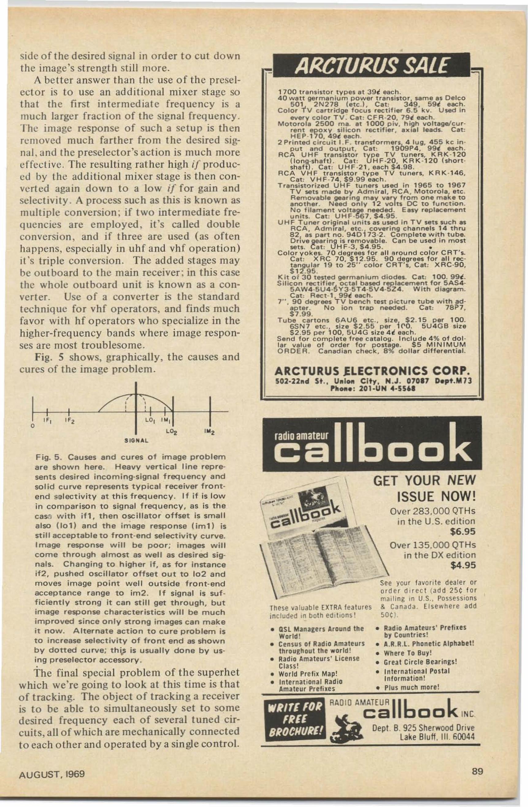
F ig. 5 . Causes and cures of image problemare shown h ere . Heavy vertical line represents desi red incoming-signal frequency andsolid c u rve re presen t s typ ical receiver fro ntend set ec t tv tt v at th is f requenc y . If if is lo win compariso n to sig n a l frequenc y, as is t hece so w it h if 1, t hen osc illato r offset is smallalso (101) and the im age re sponse ( Irn t} isstill acceptable to front-end select ivity c u rve.Image response w ill be poor; images w illcome through almost as well as desi red s ignals . Changing to higher if, as for in sta nceif2, pushed osci llato r offset o ut to 10 2 andm o ves im a ge po in t we ll o utside front-endacceptance range to im 2 . If signal is suf fi ciently stro ng it can st ill get t hro u g h , butimage response characteristics w ill be muc himproved since only strong images c a n makeit now . Alternate action to c u re problem isto increase selectivity of front e nd as shownby dotted cu rve ; th j,.s is usually do ne by using p reselecto r accesso ry .
The final special problem of th e superhetwhich we' re going to look at this time is thatof tracking. The object of tracking a receiveris to be able to simultaneously set to so medesired frequency each o f severa l tuned circuits, all of which are me chanically connectedto each other and opera ted by a single co nt rol.
• Rad io Amateurs' Pnfi. esby Countries !
• A.R.R.L. Phonetic Alphabet!• Where To Buy !• Gr eat Circ le Bearings!• Inte rnatio nal Postal
Informat ion!• Plus much more!
GET YOUR NEWISSUE NOW!
Over 283.000 QTH sin t he U.S. ed ition
$6.95
Over 13 5.000 QTHsin the DX edition
$4.95
I ' RAQ IO AMATEUR 116 k~
ca 00 INC
Dept . B. 925 Sherwood Dr ivelake Bluff . III 60044
ARCTURUS lLECTRONICS CORP.502·22.d se., U..IOf'l City , N.J. 07017 D.pt.M13
pa.Of'le : 201-UH 4·5561
• QSL Managers Around theWorld!
• Censu s of Radio Amateursthroughout the world!
• Radio Amateurs' LicenseClass!
• World Prefix Map!• Internat ional Radio
Amateur Prefixes
1 700 tran sist or types at 39 t each .40 watt german iu m p o w er tran sist or, same as Delco
501 2 N 2 78 [etc.} , Cat: 349, 59 t each .Color 't v ca rt rid ge f ocus rectifier 6 .5 k v. U sed in
every co lor T V . Cat : CF R ·20. 79t each.M otorola 2 500 mao at 1000 piv. high vol tage/cu r ·
rent epoxv si licon rec ett ter , ailtial lead s. Cat :HEP·170, 49t each .
2 Pr inted ci rcu i t I .F . transformersJ.~ lug. 4 55 kc in-put and output. Cat : 19U1::1P4 . 99 t each .
RCA U H F r renststor type T V tune rs, KRK ·1 20( Io n g·sh af t). Cat : UH F -20, KRK-120 (short·shaf t). Cat : U HF -2 1 , each $ 4 .98.
R CA V HF transistor type T V tuners, KRK · 14 6.Cat: V H F · 7 4, $9 .99 each .
Transistorized U HF tu ners used in 196 5 to 19 6 7T V sets m ade b y Admiral , RCA . Motorola. etc .R emovable geaong may vary from one make toanother . Need o n ly 12 YO ts DC t o f unct ion.N o. f i tament voltage needed . Easy replacementUnits. C at : UH F·567 . $ 4 .9 5 .
U H F Tuner orip inal units as used in T V sets such asA CA. A d m ira l. etc .! covering ch an ne ls 14 th ru82, as part no. 94 0 73 -2. C o m p let e with t ube.Dove geari ng is rem o vabl e. C an be u sed i n mostsou. Cat : UH F·3 . $ 4 .95 . •
C o lo r yokes. 70 d egrees for al l aro u n d co lo r CRT 's.Cat: XR C 70. $ 12.95. 9 0 degrees f o r all rec t an gu lar 19 t o 25" co lo r CA T's, CIIt : XRC·90 ,$ 12.9 5 .
Ki t 01 3 0 t ested germanium diodes. C at : 100. 99t .S i l ic o n rectif ier.. o c tat based replacement for 5AS4
5AW 4 ·5U4 ·:>Y3·5T 4 ·5V 4 ·5Z 4 . With diagram.Cat : Reet · l 99t each .
7" . 90 degrees TV bench t est p ictu re tube wi t h ad-ap ter. No ion trap n eeded . C at : 78P7.$ 7.99.
Tu be carto n s 6AU6 etc., si l e! $2 . 15 per 100.6S N 7 etc .• stee $2.55 per ('0. 5U 4 GB s tee$2.95 p er 100 . 5 U 4G erae 4t each.
Send for co m p let e free cat al og. Inclu d e 4 % o f corlar valu e o f o rder f or p o st age. $5 MI NIMUMO RD E R . Can adian check . 8 % do ll ar d ifferent ial.
-See your tevonte dealer oror der dtr ec t (ad d 25 (: fo rmailing in U.S., Posse ssions
These valuable EXTRA featur es & Canada. Elsewhere addincluded in both editions! 50(: }.
WRITE lORIREI
BROCHI/RE!
SIO NAl
,,,/'
side of the desired signal in order t o cut downthe image's st re ngt h still more.
A be tter answer than the use of the preselector is to use an addi tional mixer stage sothat th e first intermediat e freq uency is amuch larger fracti on of the signal frequen cy .The image response of such a set up is thenremoved much farther from the desired signal, and the presclector 's action is much moreeffect ive. The resulting rat her high if produccd by the additional mixer stage is then converted again down to a low if for gain andselect ivity. A process such as this is known asmultiple conversion; if two intermediate frequencies are emplo yed , it's ca lled doubleconversio n, and if t hree are used (as oftenhappens, especially in uh f and vhf o peration )it's trip le conversion. The added stages maybe o utboard to the main receiver : in this casethe whole outboard unit is known as a converter. Use of a co nverter is the standardtechnique for vhf operators , and finds muchfavo r with hf operators who specialize in t hehigher-frequency bands where image responses are most t roublesome.
Fig. 5 shows, graphically, the causes andcures of the image problem .
AUGUST. 1969 89
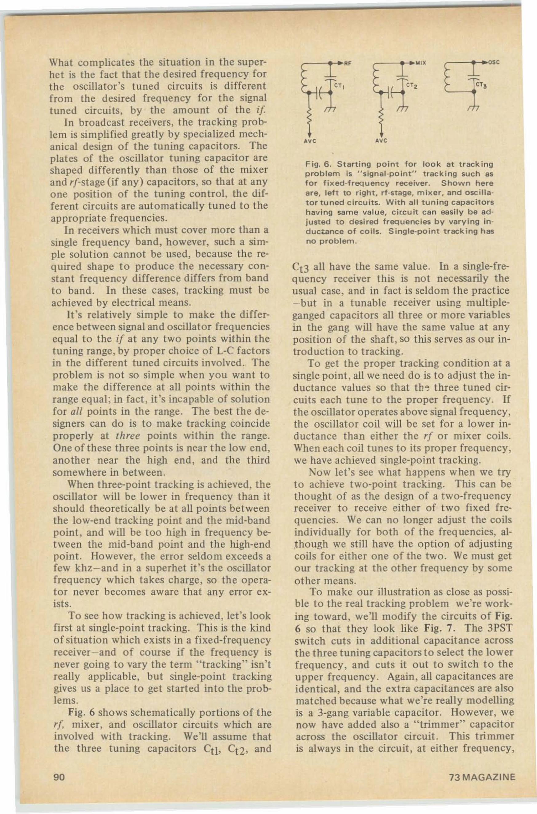
Fig. 6. Starting point for look at trackingproblem is " signal-po int" tracking such asfor fixed-frequency receiver. Shown hereare, left to right, rf-stage, mixer, and oscillator tuned ci rcuits. With all tun ing capacitorshaving same val ue, cir.cuit can easily be adjusted to desired frequencies by varying tnductance of coils . Single-point tracking hasno problem.
- - ......."
."
r--......"
Ct3 all have the same value . In a single-frequency receiver this is not necessarily theusual case, and in fact is seldom the pract ice- but in a tunable receiver using multipleganged capacitors all three or more variablesin the gang will have the same value at anyposition of the shaft , so this serves as our introduction to tracking .
To get th e proper tracking condition at asingle point , all we need do is to adjust the inductance values so that the three tuned circuits each tune to the proper frequency . Ifthe oscillator operates above signal frequency ,the oscillator coil will be set for a lower inductance than either the rl or mixer coils.When each coil tunes to its proper frequency ,we have achieved single-point tracking.
Now let's see what happens when we tryto achieve two-point tracking. This can bethought of as the design of a two-frequencyreceiver to receive either of two fixed frequencies. We can no longer adjust the coilsindividually for both of the frequencies, although we still have the option of adjustingcoils for either one of the two. We must getour tracking at the other frequency by someother means.
To make our illustration as close as possible to the real tracking problem we're working toward , we'll modify the circuits of Fig.6 so that they look like Fig. 7. The 3PSTswitch cuts in additional capacitance acrossthe three tuning capacitors to select the lowerfrequency, and cuts it out to switch to theupper frequency . Again, all capacitances areidentical, and the extra capacitances are alsomatched because what we're really modellingis a 3-gang varia ble capacitor. However, wenow have added also a "trimmer" capacitoracross the oscillator circuit. This trimmeris always in the circuit , at either frequency,
What complicates the situation in the superhet is the fact that the desired frequency forthe oscillator's tuned circuits is differentfrom the desired frequency for the signaltuned circuits, by the amount of the if
In broadcast receivers, the tracking problem is simplified greatly by specialized mechanical design of the tuning capacitors. Theplates of the oscillator tuning capacitor areshaped differently than those of the mixerand ,[-stage (if any) capacitors, so that at anyone position of the tuning control, the different circuits are automatically tuned to theappropriate frequencies.
In receivers which must cover more than asingle frequency band, however, such a simple solution cannot be used, because the required shape to produce the necessary constant frequency difference differs from bandto band. In these cases , tracking must beachieved by electrical means.
It's relatively simple to make the difference between signal and oscillator frequenciesequal to the If at any two points within thetuning range, by proper choice of L-C factorsin the different tuned circuits involved . Theproblem is not so simple when you want tomake the difference at all points within therange equal; in fact, it's incapable of solutionfor all points in the range. The best the designers can do is to make tracking coincideproperly at three points within the range.One of these three points is near the low end,another near the high end, and the thirdsomewhere in between .
When three-point tracking is achieved, theoscillator will be lower in frequency than itshould theoretically be at all points betweenthe low-end tracking point and the mid-bandpoint, and will be too high in frequency between the mid-band point and the high-endpoint. However, the error seldom exceeds afew khz-and in a superhet it's the oscillatorfrequency which takes charge, so the operator never becomes aware that any error exists.
To see how tracking is achieved, let's lookfirst at single-point tracking. This is the kindof situation which exists in a fixed-frequencyreceiver-and of course if the frequency isnever going to vary the term "tracking" isn'treally applicable, but single-point trackinggives us a place to get started into the problems.
Fig. 6 shows schematically portions of ther], mixer, and oscillator circuits which areinvolved with tracking. We'll assume thatthe three tuning capacitors CU, Ct2, and
90 73 MAGAZINE
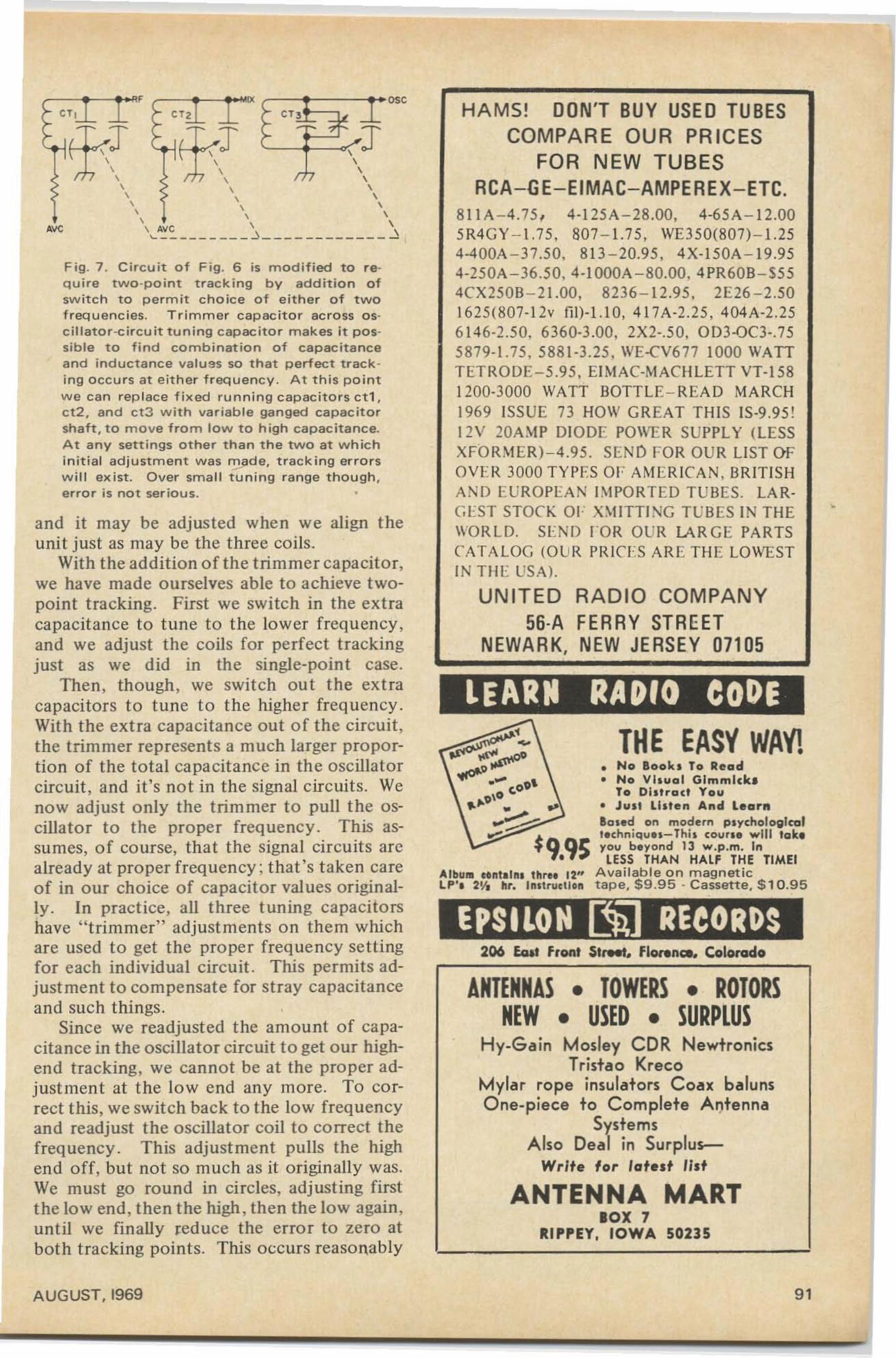
206 foIt front $,,,,,. flcu.nc.. Colorado
ANTENNA MARTlOX 7
RIPPEY. IOWA 50235
ROTORSSURPLUS
THE EASY WA'i!• No Book, To Read• No Visuol Gimmick.
To Dlslrad You• JUI' Lllten And LearnBOled on modern PlychologlcolIlchniqu II-Thii COl,lUI will toklyou blyond 13 w .p.m. 'n
LESS THAN HALF THE TlMEIAvai lab le o n magn et ictape, $9.95 - C assette , $ 10.95
• TOWERS •• USED •
Hy-Gain Mosley CDR NewtronicsTristao Kreco
Mylar rope insulators Coax balunsOne-piece to Complete Antenna
SystemsAlso Deal in Surplus
Write 'or latest list
ANTENNASNEW
HAMS! DON'T BUY USED TUBESCOMPARE OUR PRICES
FOR NEW TUBESRCA-GE-EIMAC-AMPEREX-ETC.
8 11A-4. 75, 4-125A -28 .00, 4-65A-1 2.005R4GY -1.75, 807-1.75, WE350(807)-1.254-400A -37.50. 813 -20.95. 4 X- 150A-1 9.954-25 0A -36 .50, 4-tOOOA -80.00 . 4PR60B-S554CX250B -21.00, 8236 -12 .95, 2E26-2 .501625(807-1 2v nn-i .io. 41 7A-2.25, 404 A-2.256 146-2 .50_ 6360-3.00. 2X2 -.50, OD3-00-.755879-1.75. 588 1-3.25, WE-eV6 77 1000 WATTTETRODE-5 .95. EIMAC-~tACHLETT VT-1581200-3000 WATT BOTTLE-READ MA RCH1969 tSSUE 73 HOII' GREAT T HIS IS-9.95!12V 20A~IP DIOOE PO\\T:R SUPPLY (LESSXFOR~IER)-4 .95 . SEND FOR OUR LIST OFOVE R 3000 TY PES OE AME RICAN . BRtTIS HAND EUROPEAN t ~ I PO RTED TUBES . LARGES T STOCK OF XIlITTING T UBES IN THEIIORLD. SEND FOR OUR lARGE PARTSCATA LOG (O UR PRinS ARE T HE LOII'ESTIN TIlE US A).
UNITED RADIO COMPANY56-A FERRY STREET
NEWARK. NEW JERSEY 07105
Albura "n111n, three 12"LP', 2V. hr. Instruction
Fig. 7 . Circuit of Fig. 6 is modified to r equire two-point tracking by addition ofswitch to perm it choice of either o f twof requenc ies. Tr immer capac itor acro ss osci llato r -circuit tun ing capacitor makes it possible to find combination of capacitanceand inductance vetues so that perfect track ing occurs at either f reque nc y . At thi s po intwe ca n replac e fixed ru nni n g capacito rs etl,c t z , and ct3 w i t h variable ganged capacitorshaft, to move from low to high capacitance.At any settings other th a n t he two at w h ic hinit ia l ad justment was m ad e, t rack ing e r rorsw ill ex ist. Over small i~ ning range t ho ugh,e rro r is not serious. .
,_-,-_~F IX OSC
\, ~!, >- (J'rh \, / 1 \, , ,, , ,, , ',, ' ,
A'IC \ Aye \ \
~ - - - - - --- - ~- - - - - - - - - - - - ~
and it may be adjusted when we align t heunit just as may be the three coils.
With the addition of the trimmer capacitor,we have made ourselves able to achieve twopoint tracking. First we switch in the ext racapacita nce to tune to the lower frequ ency ,and we adjust the coils fo r perfect trackingjust as we did in the single-point case.
Then, though , we switch out t he ext racapacitors to tune to the higher freq uency.Wit h the extra capacitance out of the circuit,the trimmer represents a much larger proportion of the to tal capacitance in the oscillatorcircuit , and it's not in the signal circuits. Wenow adjust only the trimmer to pull t he oscillator to the proper frequency . This assumes, of course, tha t the signal circuit s arcalready at proper freq uency : that 's taken ca reof in our choice of capacitor values originally . In practice, all three tuning capacitorshave " trimmer" adjust ments on them whichare used to get the proper freq ue ncy se tt ingfor each individua l circuit. This permits adjustment to compensate for st ray capacitanceand such things.
Since we readj usted the amount of capacitance in the oscillator circuit to get our highend tracking, we cannot be at the proper adjust men t at the low end any more. To correct this, we switch back to the low frequencyand readjust the oscillator coil to correct thefrequency . This adj ust ment pulls the highend o ff, but not so much as it o riginally was.We must go rou nd in ci rcles, adj usting firstthe low end, then the high, then the low again,unt il we fi nally reduce the error to zero atboth tracking points. This occurs reasonably
AUG UST. 1969 91
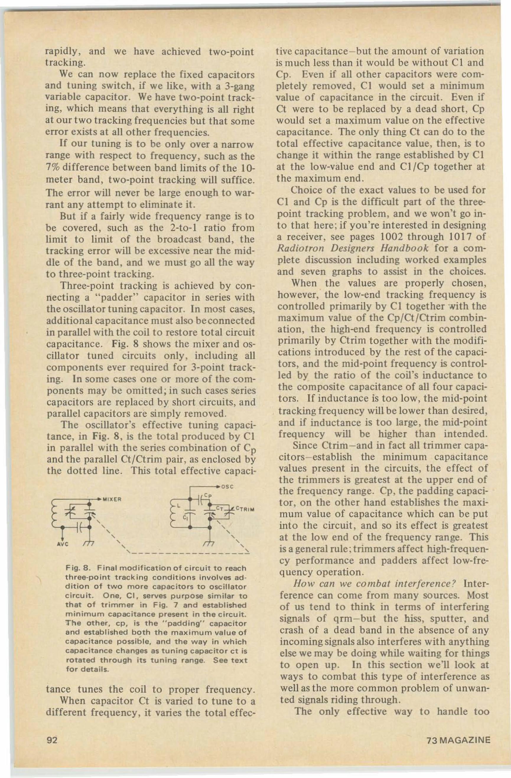
tive capacitance -but the amount of variationis much iess than it would be without CI andCp. Even if all other capacitors were completely removed, CI would set a minimumvalue of capacitance in the circuit. Even ifCt were to be replaced by a dead short , Cpwould set a maximum value on the effectivecapacitance. The only thing Ct can do to thetotal effective capacitance value, then, is tochange it within the range established by CIat the low-value end and CI/Cp together atthe maximum end.
Choice of the exact values to be used forCI and Cp is the difficult part of the threepoint tracking problem, and we won't go into that here; if you're interested in designinga receiver, see pages 1002 through 10 I7 ofRadioiron Designers Handbook for a complete discussion including worked examplesand seven graphs to assist in the choices.
When the values are properly chosen,however, the low-end tracking frequency iscontrolled primarily by CI together with themaximum value of the Cp/Ct/Ctrim combination, the high-end frequency is controlledprimarily by Ctrim together with the modifications introduced by the rest of the capacitors , and the mid-point frequency is controlled by the ratio of the coil's inductance tothe composite capacitance of all four capacitors. If inductance is too low, the mid-pointtracking frequency will be lower than desired,and if inductance is too large, the mid-pointfrequency will be higher than intended.
Since Ctrim-and in fact all trimmer capacitors-establish the minimum capacitanceval ues present in the circuits, the effect ofthe trimmers is greatest at the upper end ofthe frequency range. Cp, the padding capacitor, on the other hand establishes the maximum value of capacitance which can be putinto the circuit, and so its effect is greatestat the low end of the frequency range. Thisis a general rule; trimmers affect high-frequency performance and padders affect low-frequencyoperation .
How can we combat interference? Interference can come from many sources. Mostof us tend to think in terms of interferingsignals of qrm-but the hiss , sputter, andcrash of a dead band in the absence of anyincoming signals also interferes with anythingelse we may be doing while waiting for thingsto open up . In this section we'll look atways to combat this type of interference aswell as the more common problem of unwanted signals riding through.
The only effective way to handle too
Fig.8. Final modification of circuit to reachthree-polnt tracking conditions involves ad ·dition of two more capacitors to oscillatorcircuit. One. CI, serves purpose similar tothat of trimmer in Fig. 7 and establishedminimum capacitance present in the circuit.The other, cp, is the " pad d ing" capacitorand established both the maximum value ofcapacitance possible, and the way in whichcapacitance changes as tuning capacitor ct isrotated through its tuning range. See textfor details.
tance tunes the coil to proper frequency .When capacitor Ct is varied to tune to a
different frequency, it varies the total effec-
CT CT RIM
l~*~" -. Lj__!'",~,-, ,
-, -,-, ,,---------- -- -- - --~
rapidly, and we have achieved two-pointtracking.
We can now replace the fixed capacitorsand tuning switch, if we like, with a 3-gangvariable capacitor. We have two-point tracking, which means that everything is all rightat our two tracking frequencies but that someerror exists at all other frequencies.
If our tuning is to be only over a narrowrange with respect to frequency, such as the7% difference between band limits of the 10meter band, two-point tracking will suffice.The error will never be large enough to warrant any attempt to eliminate it.
But if a fairly wide frequency range is tobe covered, such as the 2-to- 1 ratio fromlimit to limit of the broadcast band, thetracking error will be excessive near the middle of the band, and we must go all the wayto three-point tracking.
Three-point tracking is achieved by connecting a "padder" capacitor in series withthe oscillator tuning capacitor. In most cases,additional capacitance must also be connectedin parallel with the coil to restore total circuitcapacitance. Fig . 8 shows the mixer and oscillator tuned circuits only, incl uding allcomponents ever required for 3-point tracking. In some cases one or more of the components may be omitted; in such cases seriescapacitors are replaced by short circuits, andparallel capacitors are simply removed.
The oscillator's effective tuning capacitance, in Fig. 8, is the total produced by CIin parallel with the series combination of Cpand the parallel Ct/Ctrim pair, as enclosed bythe dotted line. This total effective capaci-
92 73 MAGAZINE
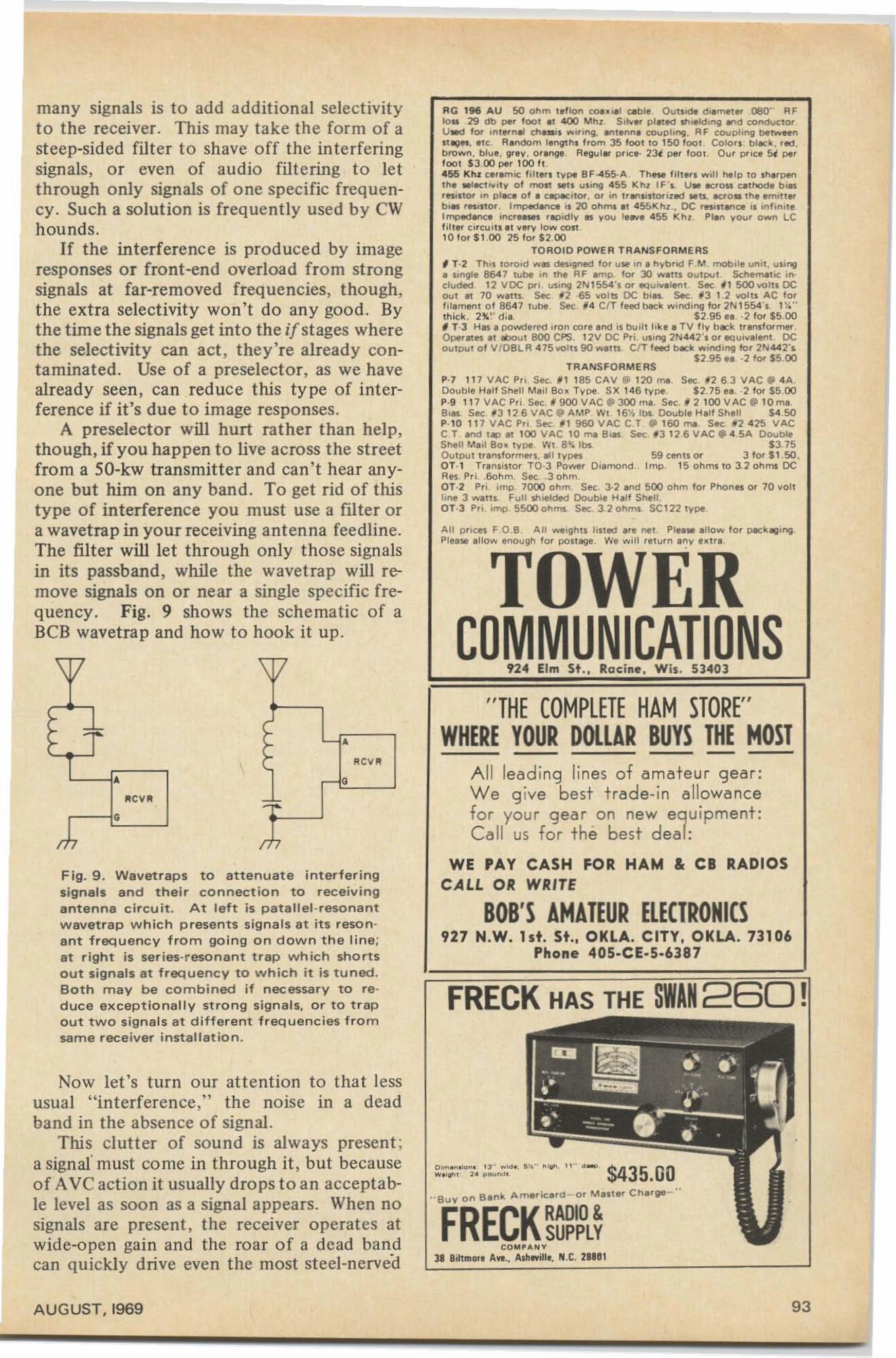
many signals is to add add itional selectivityto the receiver . This may take the form of asteep-sided filt er t o shave off the interferingsignals, or even of audio filt ering t o letthrough only signals of one specific freque ncy. Such a solution is frequently used by CWh ounds.
If the interference is produced by imageresponses or front-end overload from strongsignals at far-removed freq ue ncies, though,the ext ra select ivity won 't do any good. Bythe time the signals get into the if stages wherethe selectivity can act, they're already contaminated. Use of a preselector, as we havealready seen, can reduce this type of interference if it's due to image responses.
A preselector will hurt rather than help,though, if you happen to live across t he st reetfrom a SO-kw transmitter and can' t hear anyone but him on any band . To get rid of thistype of interference you must use a filter ora wavetrap in your receiving antenna feedline.The filter will let through only those signalsin its passband, while the wave trap will remove signals on or near a single specific frequency. Fig. 9 shows the sche matic of aBCB wavetrap and how to hook it up .
RG 196 AU 50 Ohm l el lo n ~.,.' Clb le OuUodtI dil~for 080" R F10.. 29 db per 1001 .1 400 Mhz . S, ...... pllted .,.,oe!dlng I"d COndu~lor .
UMd for .nlforn" /;h........ ,..ng. Inllnn. COUpling , RF ~oup"ng be"",,,,,n"1V". '!C . R.ndom l. n.gIhl I' o m 35 1001 10 150 1001. Colo.. bllC~ . ' ed .bro....n. blue, grey . o'. nge. Regul.. p,ici' 23t pe, 1001 Ou' p..ce Sf pe,1001 $3.00 per 100 fl455 KhZ cer.mic lil te.. ty pe 8F-45!>-A ThIN l ill,," .... in help 10 .hlfpenIh. WIICT" ,ly o f moll $III u ling 455 KhZ IF ·I . Uw 1Cf0lS ClThodl bi..' "1110' In pllte 0 1 • eIpK'Tor. 0 ' in tr lflllllor ized ..tI. ICrO.lhe . mll1 ..b•• """0' ImpedlnCl'l 20 Ohms II 455K hZ.• DC '"'IIIn<;l i. in" n" "1mp<td 1f'>C8 .n~'e rlP ld ly .. y-o... I"..... 455 Khl PI. n you ' o""n LCfill .. ci rClJ lIl 1I w low con1010' $100 zs fo ' $200
TOROID POWER TRANSFORMERS' T·2 Thll lo<o.d ..... oe..gned 10' u lol!'.n . hy-b'id F M. mobil" un il, uli"'ll• li ngle 864 7 lu~ .n the RF .mp. lor Xl .....n. OulpuT. Schem'h~ i".e luded 12 VDC pr;. Ullng 2N I554 '1 or l!Quivl lenl Sec. ' 1 SOO'o'OIU DC0...1 II 70 .... . n. See 12 ·65 wo lT5 DC b.... Sec. _3 1 .2 '0'0111 AC 10'III.menl 0 1 8647 lube Sec . , 4 CIT feOO blck .... inding 10, 2 N1 554', 11'."thick. 2%" d, a $2 95 II · :l lor $5 00'T·3 Hal ' pawderNl i,on co,e and ts buil l lIk e a TV fly- h ICk u . nllormerOperllll al aboul 800 CPS. I :lV DC P, i. u"ng 2N442 'I o r lIQui".I.nl DCOUlpu l 0 1 V/08L R 4 75 '0'0 111 90 .....It1 CIT leed b1c~ ....indiftglor 2N 442·..
$2.95 • • ·2 lor $5.00TRANSFORMERS
P-7 117 'lAC Pro. See. ' 1 185 CAY @ 120 mao SIC . 12 6.3 'lAC . 4A .Double Hal l Shell Mail Bo .. Type. SX 146 1ype $ 2.7 5 II. ·2 10 ' $5.00P·9 11 7 VAC P,i . SIC 11 900 VAC e aoc ma Sec. /I 2 100 VAC@ 10 ma8 .11 See 131 2 6 'lAC" AMP . WI 16 '1.. lb l. Doubl. H. II Shell $450P·l0 117 'lAC P, i S K. 1 1 960 'lAC C.T . 160 .... SIC . 1i 2 4 25 'lACC.T .ndllpll 100 'lAC 10 .... B... Sec '3 126VAC . 45A Doubles.....n Mall 80. Iype. WI 810:. Ibi $3 .75Ou l Pu l tr.nolo.mforl . • 1I 1y- PIi 59 cenllor 3 10' $1 50 ,QT· l Tranllilo. TO-3 Po""". Diamond.. Imp. 15 o hm. 10 3.20hml DCRei. P,i . .60hm. Sec .. 3 ohm.OT·2 Pri . Imp. 7000 Ohm. Sec. 3·2 .nd 500 Ohm 10 ' P ho n... 0 ' 70 vertlone 3 ""'111. Full shielded Double H.I I Shetl .OT-3 Pro. imp. 5500 ohml Sec 3:l ohml SC1:l2 Iype
All pnces F .O .8 All """ightl lilled Ife nel . Ple'$I . 110 .... 10 ' PIC ~IIlI'ng
Please alio,"" eno ugh 10' past ille . We .... ill relu,n any e..I'a
TO ERCOMMUNICATIONS
====='=':,4 Elm St .• Racine . Wis. 53403
F ig. 9 . Wa vetra p s to attenuate interferingsigna ls and their connection to rece iv in ga ntenna ci rcuit. At left is patallel-resonantwavet rap w h ic h p resen ts sig na ls at its resona nt frequenc y from go ing o n d o wn t he l ine ;at right is series-resona nt trap which shortsout signals at freq u e n cy to which it is tuned.Both m ay be combined if nec essa ry to red uce excep tionally st ro ng s igna ls, o r t o t rapout two sig nals a t d ifferent f requencies fro msame rece iver installatio n .
FRECK HAS THE SWAN 260!
"THECOMPLETE HAM STORE"WHERE YOUR DOLLAR BUYS THE MOST
All lead ing lines of amateur gea r;We g ive best trade-in allowancefor your gear on new equipment:C all us for t he best dea l:
WE PAY CASH FOR HAM & CB RADIOSCALL OR WRITE
BOB'S AMATEUR ELECTRONICS927 N.W. lst. St.. OKLA. CITY, OKLA. 73106
Phone 40S·CE·S·63B7
-
CO M. ..... V
JB U lm OfI Aft ,. A.h..;nl, N,C. 2UD1
o."' " .~. 13" ,.10• • " .. ...... . " .. . _ . $435 00w" ' l ' ......... •
"' B u Y o n B.n~ Amlf ie..d -o' M IITe, Ch..ge~ "
FRECK RADIO &SUPPLY
RCVA
IICVII
A
G
Now let 's turn o ur attention to t ha t lessusual " interference," the noise in a deadband in the absence of signal.
This clutter of sound is always present ;a signal' must co rne in through it , but becauseof AVC action it usually dro ps to an acceptable level as soon as a signal appears. When nosignals are present , the receiver operates atwide-open gain and the roa r of a dead ba ndcan quickly drive even the most steel-nerved
A UG UST, 1969 93
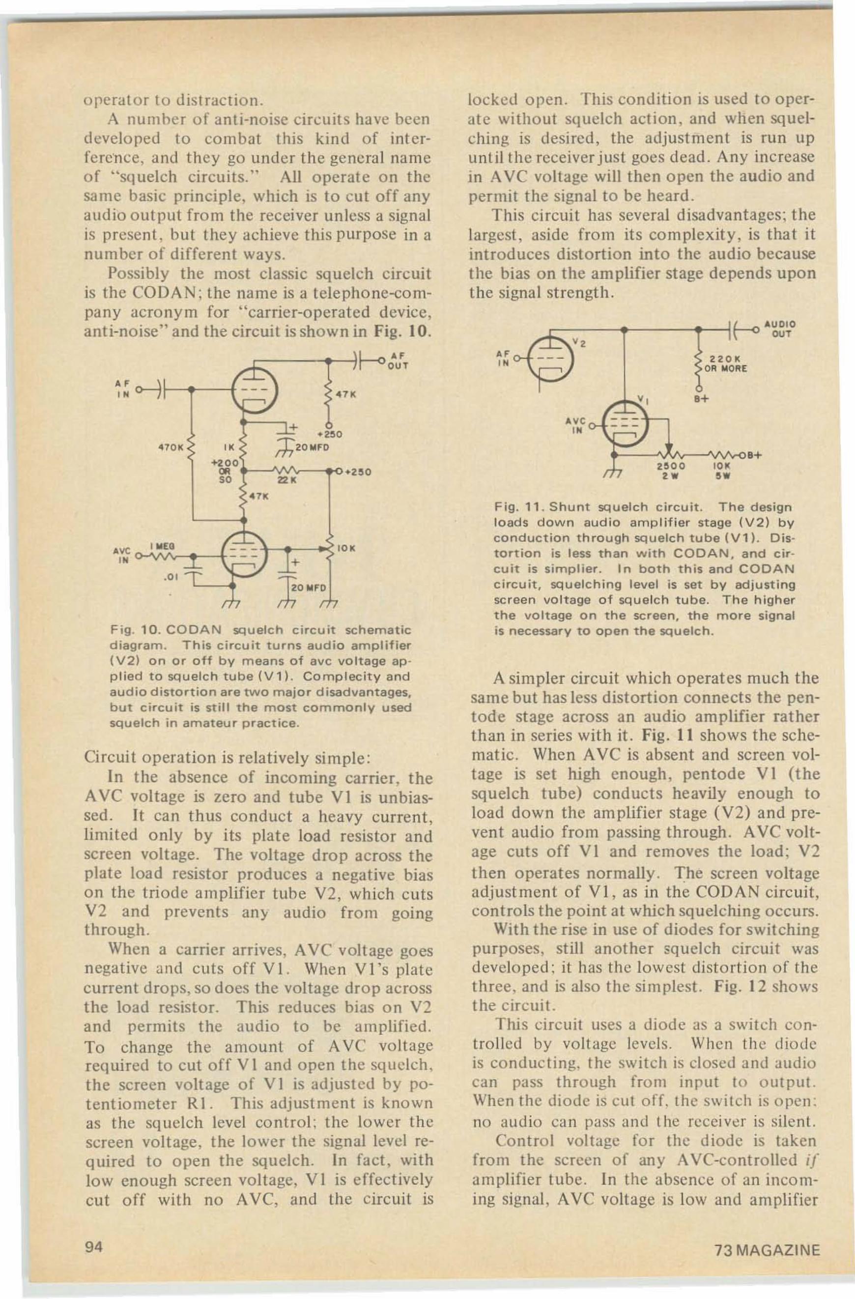
Fig. 10. COOAN squelch ci rcuit sch e ma t icdiag ram. T h is ci rc uit t ur n s a u dio am p li f ier(V2) on or off b y means of ave voltage applie d to sq uelc h tube ( V 1). Co m p lec it y a nda u di o d istortio n are two majo r di sadvanta ges,but ci rcuit is still the most commo n ly u sedsq uelch in amateu r p ractice.
.+
L....r. "'UO IO\ ~ OUT
,w,w
,"
I '
0-
r-'.2: 2: 0 I(
oa MOAE
t':. vB+
AVf o- ___'"
2~ O O '0 '
A simpler circuit which operat es much thesa me but has less distort ion connects the pentode stage across an audio amplifier rat herthan in series with it. Fig . 11 shows the schematic . When AVC is absent and screen vo ltage is set high enough, pentode VI (thesquelch tube) conducts heavily enough toload down the amplifier stage (V2) and preven t audio from passing through . AVC vo ltage cuts o ff V I and removes the lo ad ; V2then opera tes normally . The screen voltageadj ust ment of VI , as in the CODAN circuit ,contro ls the point at which squelching o ccu rs.
With the rise in use of dio des for switchingpurposes, st ill anothe r squelch ci rc uit wasdeveloped ; it has the lowest distortion o f th ethree , and is also the simplest. Fig. 12 showsthe circui t.
This ci rc uit uses a diode as a switch controlled by voltage levels. Wh en th e diodeis co nduc t ing, the switch is closed a nd audiocan P;:ISS through from input to output.When the diode is cut off. the switch is open :no au dio ca n pass and t he receiver is silent.
Contro l voltage for the diode is takenfrom the screen of any AVC-co nt ro lled ifam plifier tube . In the absence of an inco ming signal, AVC voltage is low and am plifier
F ig . 11 . S hu n t sq u e lc h c irc u it. The designloads down audi o amplifier stage (V2) byco nduct io n through squelch tu be IV1) . Dist ort ion is le ss th an with C O DA N , a nd c ircu it is stmpuer. In bot h this and CO D A Nc ircu it, squel ching level is set by adjustingscreen vo ltage of squelch tube . The higherth e vo ltage o n th e sc reen, th e more signa lis nec essar y to open th e sq uelc h.
..'"
locked open. This condition is used [ 0 o perate without sq uelch action, and when squelching is desired, the adjust men t is run upuntil the receiver just goes dead . Any increasein AVC voltage will then open th e audio andpermit the signal to be heard .
This ci rcuit has several disadvantages ; thelargest , aside from it s com plex it y, is that itint roduces distortion into the audio becausethe bias o n the amplifier stage depends uponthe signa l st rength.
'0
,r
e>-J: -\ro, ."
~ .2S0470K " ;h20MFO
+200OR .,'0 ''"'"
I IIlEO - - - '0'- - -.01 : r: :~;};O IllF;.
f,I,
"'"
operator to distraction .A numher o f ant i-noise circuits have been
d eveloped to co mba t th is kind of interte rence. and they go under the general nameof "sq uelch circu its. " All ope rate on th esa me basic principle , which is to cut off anyaud io o utput from the receiver unless a signalis present , hut they achieve this p ur pose in anumber of differen t ways.
Possibly the most classic squelch circuitis the CODAN; the name is a telephone-compan y acronym for " carrier-operated device,ant i-noise" and th e circui t is shown in Fig. 10.
L-"r--'"'out
Circui t o pera t ion is relatively simple:In the absence of incoming carrie r, the
A VC voltage is zero and tube VI is unbiassed. It can thus co nduc t a heavy current ,limited only by its plate load resistor andsc reen voltage. The voltage drop across theplate load resist or produces a negative biason the tri od e am plifie r tube V2, which cutsV2 and prevents any audio fro m goingthrough .
When a carrier arr ives, AV e voltage goesnegative and cuts off V 1. When V Ts platecurrent drops, so docs the voltage drop acrosst he lo ad resistor. This red uces bias on V2and permits t he audio to be amplified .To change the amou nt o f A VC volt agerequired to cut o ff V I and open the squelch,the screen voltage of V I is adjusted by potentio meter R1. This adj ustment is knownas the sq uelch level co ntrol: the lower th escreen vo ltage, t he lo wer the signal level req uired to open the squelch. In fact, wi thlo w enough screen vo ltage, V I is effec tive lycut o ff with no AVC, and the circ uit is
94 73 MAGAZINE
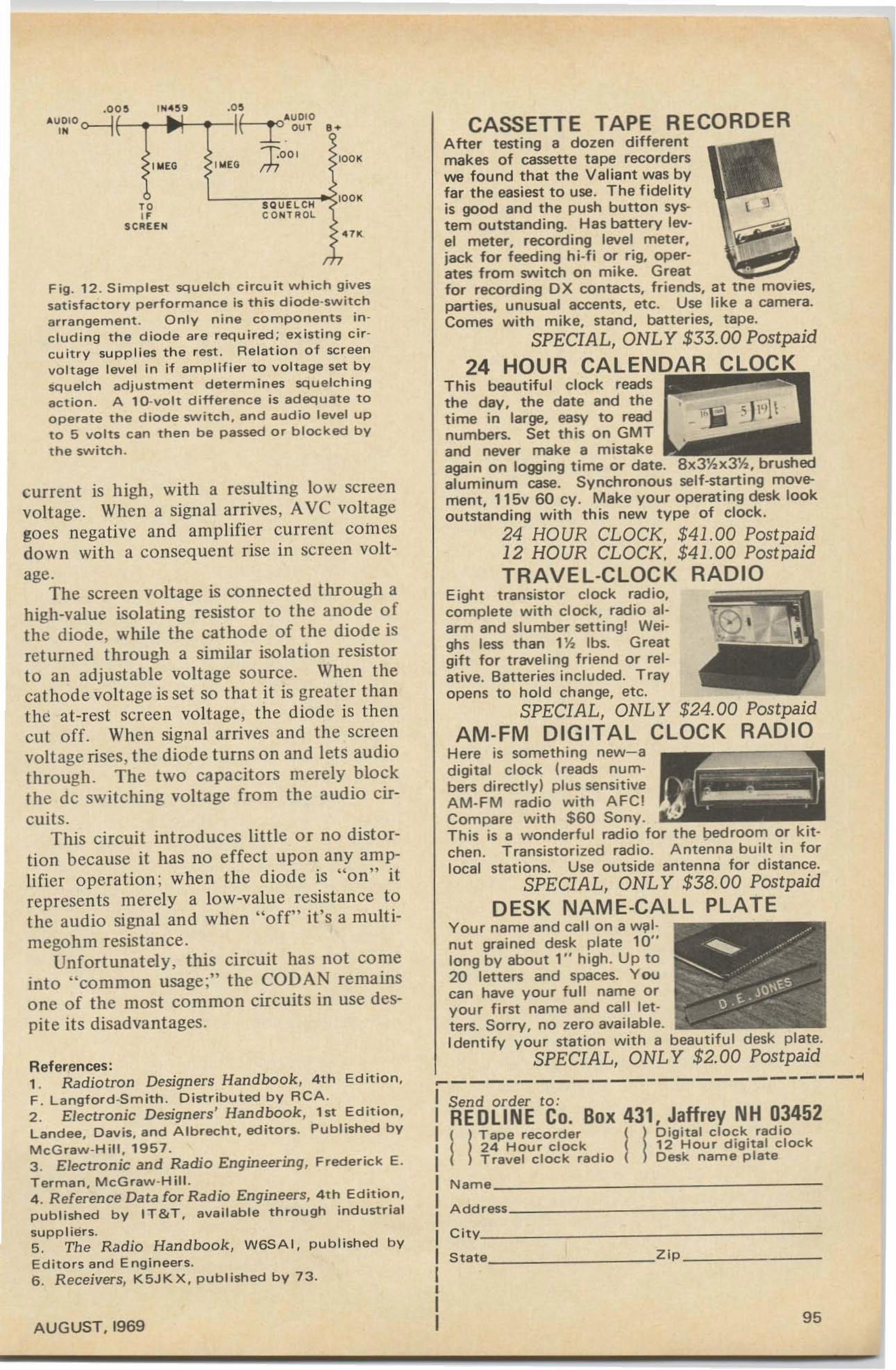
CASSETTE TAPE RECORDERAfter testing a dozen differentmakes of cassette tape recorderswe found that the Valiant was byfar the easiest to use. The fidelityis good and the push button system outstanding, Has barterv level meter. recording level meter.jack for feeding hi-fi or rig. operates from switch on mike. Greatfor recording OX contacts, friends, at tne movies.parties, unusual accents. etc. Use like a camera.Comes with mike, stand. batteries, tape.
SPECIAL, ONLY $33.00 Postpaid
24 HOUR CALENDAR CLOCKThis beautiful clock readsthe day, the date and thetime in large. easy to readnumbers. Set this on GMTand never make a mistakeagain on logging time or date. 8x3%x3%, brushedaluminum case. Synchronous self-starting movement, 115v 60 cy. Make your operating desk lookoutstanding with this new type of clock.
24 HOUR CLOCK, $41.00 Postpaid12 HOUR CLOCK, $41.00 PostpaidTRAVEL-CLOCK RADIO
Eight transistor clock radio.complete with clock, radio alarm and slumber setting! Weighs less than 1% Ibs. Greatgift for traveling friend or relative . Batteries included. Trayopens to hold change, etc.
SPECIAL, ONLY $24.00 PostpaidAM·FM DIGITAL CLOCK RADIO
Here is something new-adigital clock (reads numbers directly) plus sensitiveAM-FM radio with AFC!Compare with $60 Sony.This is a wonderful radio for the bedroom or kitchen. Transistorized radio. Antenna built in forlocal stations. Use outside antenna for distance.
SPECIAL, ONLY $38.00 PostpaidDESK NAME-CALL PLATE
Your name and call on a walnut grained desk plate 10"long by about 1" high . Up to20 letters and spaces. Youcan have your full name oryour first name and call letters. Sorry, no zero available.Identify your station with a beautiful desk plate.
SPECIAL, ONLY $2.00 Postpaid.... ooi
I Send order to :I REDLINE CO, Box 431, Jaffrey NH 03452I ( !Tape recorder (! Digital clock radioI I 24 Hour clock ( 12 Hour digital clockI Travel clock radio ( Desk name plateI Name _i Add'." _
I cnv _
I State Zip _
II
II 95
".SQUELCHCONTROL
L __...-;;;;..,..,,... lOOK
IlllEG
,."SCREEN
.CO
f----.-- ·'_-11-.0'""·"... \ ...l.. OUT 8+
Tool lOOKI"'EO rh
References:1. Radiotron Designers Handbook, 4th Ed ition,F. Langford-Smith . Distributed by RCA .2 . Electronic Designers' Handbook, 1st Edition,Landee, Davis, and Albrecht. editors. Published byMcGraw-Hili. 1957.3. Electronic and Radio Engineering, Frederick E.Terman. McGraw·HiII.4. Reference Data for Radio Engineers, 4th Edition.published by IT&T, available through industrialsuppliers.5. The Radio Handbook, W6SAI, published byEditors and Engineers.6. Receivers, K5JKX. pUblished by 73.
AUGUST. 1969
current is high, with a resulting low screenvoltage. When a signal arrives, AVe voltagegoes negative and amplifier current comesdown with a consequent rise in screen voltage.
The screen voltage is connected through ahigh-value isolating resistor to the anode ofthe diode, while the cathode of the diode isreturned through a similar isolation resistorto an adjustable voltage source. When thecathode voltage is set so that it is greater thanthe at-rest screen voltage, the diode is thencut off. When signal arrives and the screenvoltage rises , the diode turns on and lets audiothrough . The two capacitors merely blockthe dc switching voltage from the audio circuits.
This circuit introduces little or no distortion because it has no effect upon any amplifier operation; when the diode is "on" itrepresents merely a low-value resistance tothe audio signal and when "off" it's a multimegohm resistance .
Unfortunately, this circuit has not comeinto "common usage;" the CODAN remainsone of the most common circuits in use despite its disadvantages.
Fig . 12 . Simplest squelch circuit which givessatisfactory performance is this diode-switcharrangement . Only nine components in cluding the diode are required; existing circuitry supplies the rest . Relation of screenvoltage level In if amplifier to voltage set bysquelch adjustment determines squelchingaction . A to-von difference is adequate tooperate the diode switch , and audio level upto 5 volts can then be passed or blocked by
the switch.
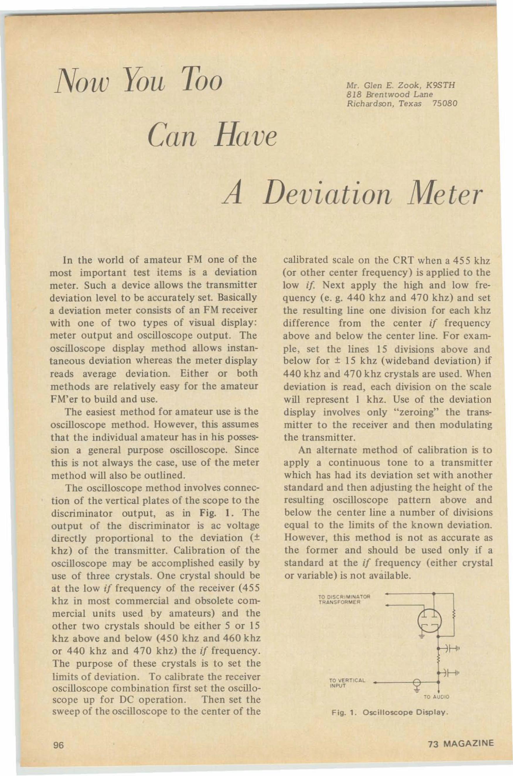
Nou. lOLL Too Mr. Glen E. Zook, K9STH81 8 Brentwood LaneRichardson , Texas 75 080
Can Have
A Deviation Me tel'
TO AUDIO
Fig. 1. Oscilloscope Display.
calibrated scale on the CRT when a 455khz(or other center frequency) is applied to thelow if Next apply the high and low frequency (e. g. 440 khz and 470 khz) and setthe resulting line one division for each khzdifference from the center if frequencyabove and below the center line. For example, set the lines 15 divisions above andbelow for + 15 khz (wideband deviation) if440 khz and 470 khz crystals are used. Whendeviation is read, each division on the scalewill represent 1 khz. Use of the deviationdisplay involves only "zeroing" the transmitter to the receiver and then modulatingthe transmitter.
An alternate method of calibration is toapply a continuous tone to a transmitterwhich has had its deviation set with anotherstandard and then adjusting the height of theresulting oscilloscope pa ttern above andbelow the center line a number of divisionsequal to the limits of the known deviation.However, this method is not as accurate asthe former and should be used only if astandard at the if frequency (either crystalor variable) is not available.
In the world of amateur FM one of themost important test items is a deviationmeter. Such a device allows the transmitterdeviation level to be accurately set. Basicallya deviation meter consists of an FM receiverwith one of two types of visual display :meter output and oscilloscope output. Theoscilloscope display method allows instantaneous deviation whereas the meter displayreads average deviation. Either or bothmethods are relatively easy for the amateurFM'er to build and use.
The easiest method for amateur use is theoscilloscope method. However, this assumesthat the individual amateur has in his possession a general purpose oscilloscope. Sincethis is not always the case, use of the metermethod will also be outlined.
The oscilloscope method involves connection of the vertical plates of the scope to thediscriminator output, as in Fig. I. Theoutput of the discriminator is ac voltagedirectly proportional to the deviation (+khz) of the transmitter. Calibration of theoscilloscope may be accomplished easily byuse of three crystals. One crystal should beat the low if frequency of the receiver (455khz in most commercial and obsolete commercial units used by amateurs) and theother two crystals should be either 5 or 15khz above and below (450 khz and 460 khzor 440 khz and 470 khz) the if frequency.The purpose of these crystals is to set thelimits of deviation . To calibrate the receiveroscilloscope combination first set the oscilloscope up for DC operation. Then set thesweep of the oscilloscope to the center of the
TO DI$C Rl o,Il " ATORT~A"SFOR"'€R
TO VE~T IC AL
INPUT
c:--
:1H
r-JH''f
96 73 MAGAZINE
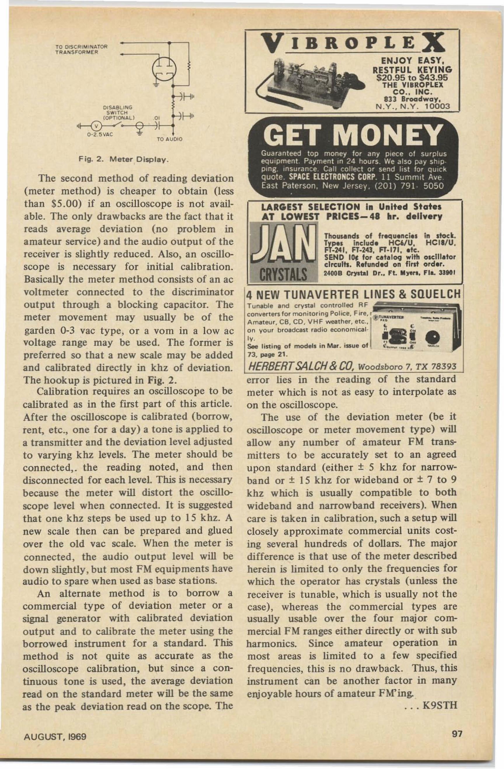
LARGEST SELECTION In United StatesAT LOWEST PRICES- 48 hr. dellyery
Thous.nds of fr~u.nel.s In stock.Types Includ. HC6IU. HCII/U.FT~241. FT~243. FT·171••te,SEND 10, tor e.t.loq wlft! osclll.torelrculh. R.funded on first order.2400B Cf'Yltal Dr.. Ft. lIIyer•• flL 33901
VIBROPLEXENJOY EASY,
RESTFUL KEYING$20.95 to $43.95
THE VIBROPLEXco.. INC.
813 Broadway,N .Y . . N .Y . 10003
T unable and crystal co nt ro ll ed R Fconver ters f or moni loring Police. Fire, ' (!l, nnuA mat eur CB , CD , VHF weather, etc.. .
~~ you r 'b roadcast radio econom ical- j-.:ll •v ..~-See list ing of modell in Mar. issue of <_ .... ... - ...
73, pail' 21 .
HERBERTSALCH& CO. Woodsboro 7, TX 78393
error lies in the reading of the standardmeter which is not as easy to interpolate ason the oscilloscope.
The use of the deviation meter (be itoscilloscope or meter movement type) willallow any number of amateur FM transmitters to be accurately set to an agreedupon standard (either + 5 khz for narrowband or + 15 khz for wideband or + 7 to 9khz which is usually compatible to bothwideband and narrowband receivers). Whencare is taken in calibration, such a setup willclosely approximate commercial units costing several hundreds of dollars. The majordifference is that use of the meter describedherein is limited to only the frequencies forwhich the operator has crystals (unless thereceiver is tunable, which is usually not thecase) , whereas the co mmercial types areusually usable over the four major commercial FM ranges either directly or with subharmonics. Since amateur operation inmost areas is limited to a few specifiedfrequencies, this is no drawback. Thus, thisinstrument can be another factor in manyenjoyable hours of amateur FM'ing.
... K9STH
Fig. 2. Meter Display.
TO AUDI O
OISABll P<lGS .... ITC H
(OP TIQP<l ALl ,0 1
,,~. Q)0-2 ~VAC "':"
The second method of reading deviation(meter method) is cheaper to obtain (lessthan $5.00) if an oscilloscope is not available. The only drawbacks are the fact that itreads average deviation (no problem inamateur service) and the audio output of thereceiver is slightly reduced . Also. an oscilloscope is necessary for initial calibration.Basically the meter method consists of an acvoltmeter connected to the discriminatorout put through a blocking capacitor. Themeter movement may usually be of thegarden 0-3 vac type, or a vom in a low acvoltage range may be used. The former ispreferred so that a new scale may be addedand calibrated directly in khz of deviation.The hookup is pictured in Fig. 2.
Calibration requires an oscilloscope to becalibrated as in the first part of this article.After the oscilloscope is calibrated (borrow.rent. etc.• one for a day) a tone is applied toa transmitter and the deviation level adjustedto varying khz levels. The meter should beconnected, . the reading noted, and thendisconnected for each level. This is necessarybecause the meter will distort the oscilloscope level when connected. It is suggestedthat one khz steps be used up to 15 khz. Anew scale then can be prepared and gluedover the old vac scale. When the meter isconnected . the audio out put level will bedown slightly. but most FM equipments haveaudio to spare when used as base sta tions.
An alternate method is to borrow acommercial type of deviation meter or asignal generator with calibrated deviationout put and to calibra te the meter using theborrowed instrument for a standard. Thismethod is not quite as accurate as theoscilloscope calibration, but since a continuous tone is used, the average deviationread on the standard meter will be the sameas the peak deviation read on the scope. The
TO OISC RI "'I P<l ATORTR A P<lSF"OR "'ER
AUGUST. 1969 97
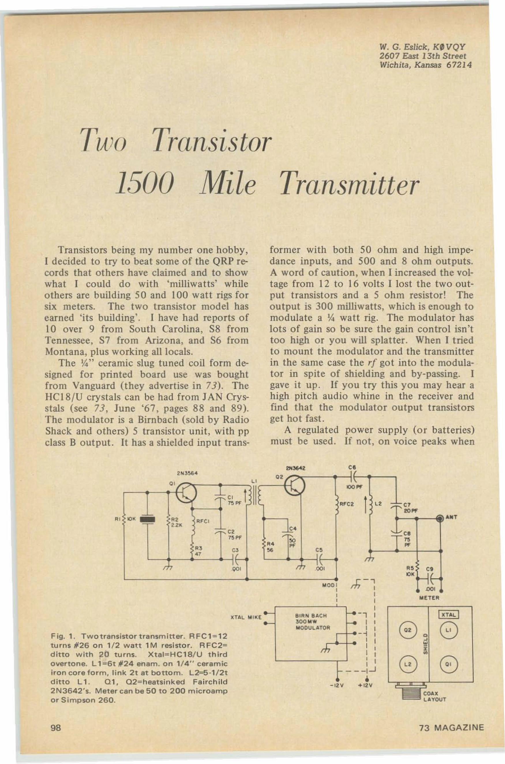
W. G. Eslick, K0 VQY2607 East 13th StreetWichita, Kansas 67214
Tum Transistor
1500 Mile Transmitter
Transistors being my number one hobby,I decided to try to beat some of the QRP records that others have claimed and to showwhat I could do with 'milliwatts' whileothers are building 50 and 100 watt rigs forsix meters. The two transistor model hasearned 'its building' . 1 have had reports of10 over 9 from South Carolina, S8 fromTennessee, S7 from Arizona, and S6 fromMontana, plus working all locals.
The ~" ceramic slug tuned coil form designed for printed board use was boughtfrom Vanguard (they advertise in 73). TheIIC18 /U crystals can be had from JAN Crysstals (see 73 , June '67, pages 88 and 89).The modulator is a Birnbach (sold by RadioShack and others) 5 transistor unit, with ppclass B output. It has a shielded input trans-
former with both 50 ohm and high impedance inputs, and 500 and 8 ohm outputs.A word of caution, when I increased the voltage from 12 to 16 volts [ lost the two output transistors and a 5 ohm resistor! Theoutput is 300 milliwatts, which is enough tomodulate a Y. watt rig. The modulator haslots of gain so be sure the gain control isn'ttoo high or you will splatter. When J triedto mount the modulator and the transmitterin the same case the r[ got into the modulator in spite of shielding and by-passing. Jgave it up . If you try this you may hear ahigh pitch audio whine in the receiver andfind that the modulator output transistorsget hot fast.
A regulated power supply (or batteries)must be used . If not, on voice peaks when
......a
ccexLAYOUT
METER
(0 (0
,,I
-, II ,
r1f--~ :, II ,I I,, I
- - -l~
•+12V-12V
81RN 8.o.CH300M*MODULATOR
2N 3~4 g,g , "
*" 1~
.....1" .. AFC2 ca C7
lOll .;;; = "'..,"' RF CI~~ W
; :::: ~2 ~.; ~~"1~PF r., rs" .. ..
" n_ ,.~~" ,
r :;" r: :;" ..+",
MOD I rf-i, DO<
XTAL MII<[
Fig. 1. Twotransistor transmitter. RFC1 =12turns #26 on 1/2 watt 1M resistor. A FC2=ditto with 20 turns. Xtal=HC18/U thirdovertone. L 1"'6t #24 enam. on 1/4" ceramiciron core form, link 2t at bottom. L2--5 ·1/2tditto L 1. 01, 02==heatsinked Fairchild2N3642's. Meter can be 50 to 200 microampor Simpson 260.
"
98 73 MAGAZINE
Bran~ new flyer now out 969J2 INCRmlBU BARGAINS wrne for your free co~y to~ay.
THE DENSON ELECTRONICS CORP.Post Office Box 85 (203) 875-5198 Rockville. Connecticut 06066
the transmitter final and modulator stagesdraw current, your voltage will drop and thefinal result is downward modulation plusFM'ing.
In designing the transmitter, be sure allemitter and collector leads (either wiring orprinted board) are very short . The shieldsbetween stages are printed board cut to sizeand soldered on. Make all grounds on theprinted board wide (I make a wide groundall around the board and down through thecenter where the shield goes. See Fig. I.Coat the printed board 'wiring' with solderto lower the resistance (it pays!).
Be sure the coils dip out (with a grid dipper) a little higher in frequency with thetransistor out as the "extra" capacity withthe transistor in will lower the frequency .You will find out (you tube boys) that insome circuits the transistor loads the coil(lowers the Q) to such an extent that youcannot find the dip. So have your receiverhandy to check signals also . Also be careful,in some circuits; the oscillator transistor'snot oscillating will draw more current andget hot (d ue to its being a class A stage tillit oscillates and then it is class c). Transistors are easy to blow, ask me!
Using the grid dipper in the diode position you can check each stage to see if it isworking. After the oscillator is working andthe final transistor is installed, be sure theoscillator isn't loaded so it will stop . It mayhave to be retuned. Be sure it will fire everytime the power is applied . If not , retune.
Wit h a #49 dial bulb as a dummy loadand everything connected (and working),whistle in the mike and tune the final slugfo r maxi mum brilliance and upward modulation . (I blew one bulb under modulation).Now connect the antenna and, with meterconnected in output (see diagram), check fo rmaximum output. Now check with your re-
AUGUST, 1969
WE PAY CASH
FOR TUBESLewispaul Electronics, Inc.
303 West Crescent AvenueAllandale. New Jersey 07401
How BIGGER andBETTER Than Ever!
----MAIL THIS COUPON NOW---I
N E, II . DDRess, _ II CITY: .__ STATE: '_' '' _'' '' '' ' '' ' Z IP: __ .._ IL Ifo' yo,, ' fIfE copy . • 11 061' CO _pOll Gild "'Glf. Dep'. 7J
ceiver - or better, have a ham friend a fewmiles away check your modulation. Set thegain control fo r clean aud io . Don't setthe gain while you are a foot or two awayfrom t he mike and then climb in the mikewhile dx'ing or you will overmodulate.
With good design, a good beam antenna,and of course, good skip conditions, youought to do as well as I did or better. Gooddx'ing.
Don't forger, in this design, that the"ground" on the transmitter is minus andthe ground on the modulator is plus. Followthe diagram carefully - or, so sorry - youhave ruined some transistors!
...KIIVQY
99
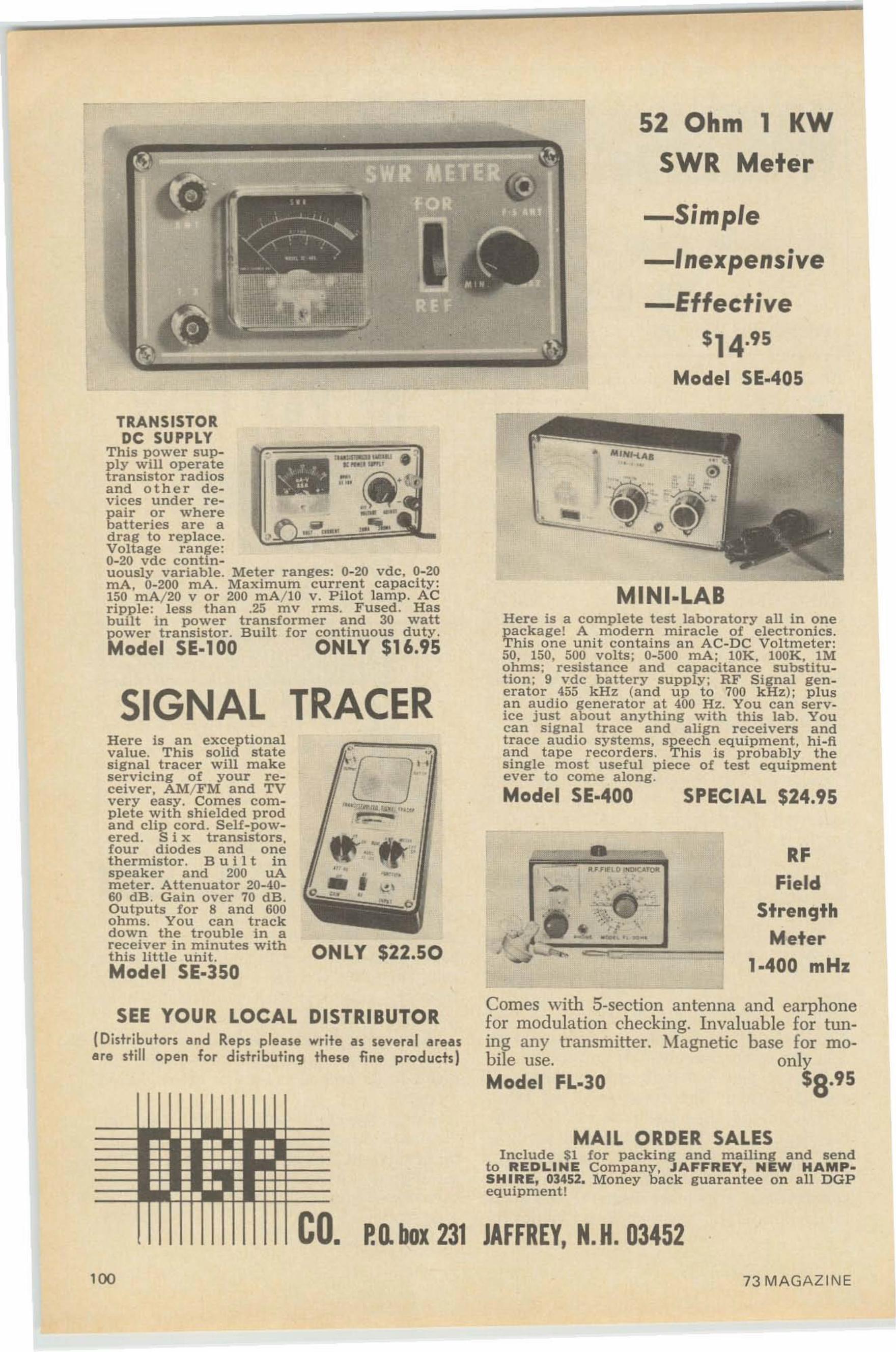
52 Ohm 1 KW
SWR Meter
-Simple
-Inexpensive
-Effective$14.95
Model SE·405
RFField
StrengthMeter
1.400 mHz
•
Here is a complete test laboratory aU in onepackage! A modern miracle of electronics.This one unit con tains an AC-DC Voltmeter :50, 150, 500 volts; 0-500 rnA ; 10K, lOOK, 1Mohms; resistance and capacitance substitution; 9 vdc battery supply; RF Signal generator 455 kHz (a n d up to 700 k Hz ); plu sa n a udio generator at 400 Hz. You can service just about anything with this lab. Youcan signal trace and align receivers andtrace audio systems, speech equipment, h i-fand tape recorders . This is probably thesingle most useful piece of test equipmentever to come along.
Model SE·400 SPECIAL $24.95
MINI-LAB
..~O"''''':'lIaIu Ill.. ,_
i_ 4
..
ONLY $22.50
....•1.. - ,.", . -.•• I!.\
" j'"
" ..-.: ,'",..ce:- -.. _........ ,- "
Here is an exceptionalvalue. T h is solid statesignal tracer will makeservicing of your receiver, AM/FM and TVvery easy. Comes complete with shielded prodand clip cord. Self-powered. Six transistors .four diodes and onethermistor. B u i I t i nspeaker and 200 uAmeter. Attenuator 20-4060 dB. Gain over 70 dB.Outputs for 8 and 600ohms. You can trackdown the trouble in areceiver in minutes witht his little unit .Model SE·350
TRAN SISTO RDC SUPPLY
This power supply will operatetransistor radiosand other devices under repair or wherebatteries are adrag to replace.Voltage range:0-20 vdc contin-uously variable . Meter ranges: 0-20 vdc. 0-20rnA, 0-200 rnA. Maximum current ca p acity :150 mAj20 v or 200 rnA/IO v. P ilot la mp. A Cripple : less than .25 mv rms. Fused. H a sbuilt in power transformer and 30 wattpower transistor. Built fo r continuous dut y .Model SE·100 ONLY $16.95
SIGNAL TRACER
SEE YOUR LOCAL DISTRIBUTOR(Distributors and Reps please write as several areasare still open fo r d istr ibuting these fine products)
Comes with 5-section antenna and earphonefor modulation checking. Invaluahle for tuning any transmitter. Magnetic base for rno-bile use. onlyModel FL.30 $8.95
MAIL ORDER SALESIn clu d e $1 for packing and mailing a nd send
to REDLINE Company, JAFFREY, NEW HAMP·SH IRE, 03452. Mo n ey b a ck guaran tee o n all DGPeq uipment!
co. P.D. box 231 JAFFREY, N. H. 03452100 73 MAGAZINE
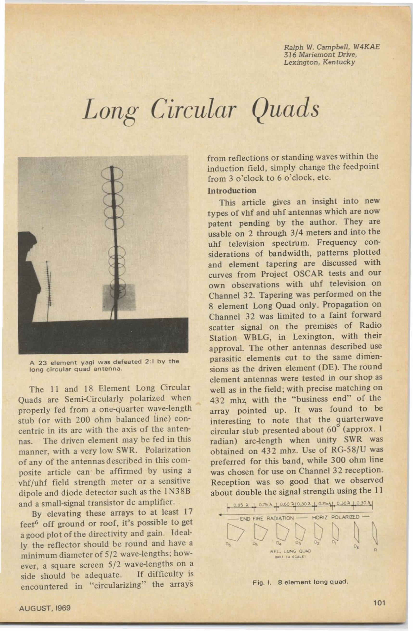
Long' Circular
Ralph W. Campbell, W4KAE3 16 Mademont Drive,Lexington, K entuck y
Quads
A 23 element vagi was defeated 2 :1 by thelong circular quad antenna.
The II and 18 Element Long CircularQuads are Semi-Circularly polarized whenproperly fed fro m a one-quarter wave-lengthstub (or with 200 ohm balanced line) concentric in its arc with the axis of the antennas. The driven element may be fed in thismanner, with a very low SWR. Polarizationof any of the antennas described in this composite article can be affirmed by using avhf/uhf field st rength me ter or a sensitived ipole and diode detector su ch as the I N38 Band a small-signal t ransistor de amplifier.
By elevating these arrays to at least 17feet" off ground or roof, it's possible to gela good plot of the directivity and gain. Ideally the reflec tor should be round and have aminimum diameter of 5/2 wave-lengths ; however, a square screen 5/2 wave-lengths on aside should be adequa te. If diffi culty isencountered in "circularizing" the arrays
AUGUST, 1969
from reflections or standing waves within theinduc t ion field , simply change th e feed poin tfrom 3 o 'clock to 6 o'clock, et c.
IntroductionThis article gives a n insight in to new
types of vhf and uhf antennas which are nowpatent pending by the auth or. They areusable on 2 through 3/4 meters and into theuhf television spect ru m. Frequency considerations of bandwidth, patterns plottedand element tapering are discussed withcurves from Project OSCAR tests and ourown observations with uhf television onChannel 32. Tapering was performed on the8 element Long Quad only. Propagation onChannel 32 was limited to a faint forwardscatter signal on the premises of RadioStation WBLG, in Lexington , with theirapproval. The other antennas described useparasitic elements cu t to the same di mensions as the driven element (DE). The roundelement antennas were tested in our shop aswell as in the field; wi th precise matching on432 mhz, with the " busi ness end" of thearray pointed up. It was found to bein te resting to note that the quarte rwavecircular stub presented about 60
0(approx. I
radian) arc-length when unity SWR wasobtained on 432 mhz. Use of RG-58/U waspreferred fo r this ba nd, while 300 ohm linewas chosen for use on Channel 32 reception.Reception was so good that we observedabout double the signal st rength using the II
I c.es x I O.1S ;t\, IO_60 1. IO, .lO l, -j ,Cl.2s '\ 'I,o..lO iI .!,o·.lO ,ll, 1I, .. I •, ,
<lEI.-. I.-c-.c, QUAD, ••,,, f O ~",.,- [l
Fig . l. 8 el ement long q uad.
101
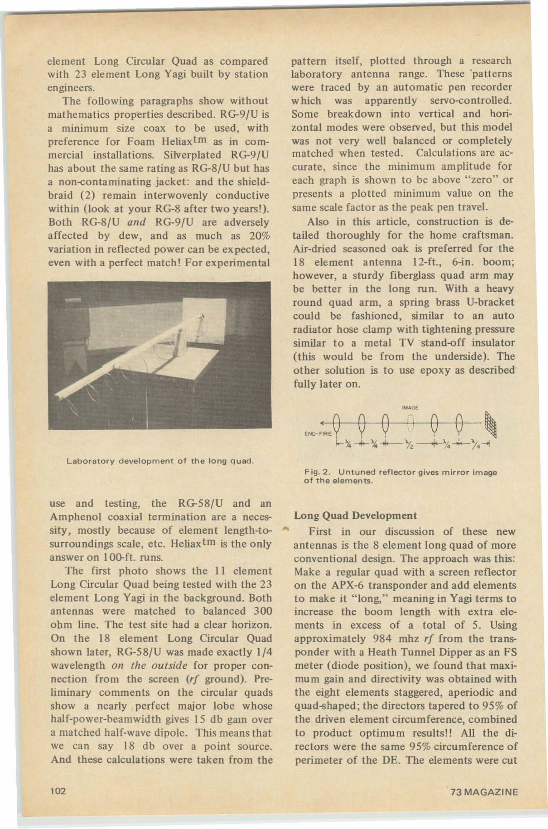
element Long Circular Quad as comparedwith 23 element Long Yagi built by stationengineers.
The foll owing paragraphs show withoutmathematics properties described. RG-9/U isa minimum size coax to be used. withpreference for Foam Heliaxtm as in commercial installations. Silverplated RG-9/Uhas about the same rating as RG-8/U but hasa non-contaminating jacket : and the shieldbraid (2) remain interwovenly conductivewithin (look at your RG-8 after two yearsl) .Both RG-8/U and RG-9/U are adverselyaffected by dew, and as much as 20%variation in reflected power can be ex pected,even with a perfect match! For experimental
Laboratory development of the long quad.
use and testing, the RG-58/U and anAmphenol coaxial termination are a necessity, mostly because of element length-to- ...surroundings scale, etc. Heliax tm is the onlyanswer on IO~ft. runs.
The first photo shows the II elementLong Circular Quad being tested with the 23element Long Yagi in the background. Bothantennas were matched to balanced 300ohm line. The test site had a clear horizon.On the 18 element Long Circular Quadshown later, RG-58/U was made exactly 1/4wavelength on the outside for proper connection from the screen (rf ground). Preliminary comments on the circular quadsshow a nearly perfect major lobe whosehal f-power-beamwid th gives 15 db gam overa matched half-wave dipole. This means thatwe can say 18 db over a point source.And these calcula tions were taken from the
102
pattern itself, plotted through a researchlaboratory antenna range. These 'patternswere traced by an automatic pen recorderwhich was apparently servo-co ntro lled.Some breakdown into vertical and horizontal modes were observed, but this modelwas not very well balanced or completelymatched when tested. Calculations are accurate, since the minimum amplitude foreach graph is sho wn to be above "zero" orpresents a plotted minimum value on thesame scale fa ctor as the peak pen travel.
Also in this article, construction is detailed thoroughly for the home craftsman.Air-dried seasoned oak is preferred for the18 element antenna 12-ft., 6-in. boom;however, a sturdy fiberglass quad arm maybe better in the long run. With a heavyround quad arm, a spring brass U-bracketcould be fashioned, similar to an autoradiator hose clamp with tightening pressuresimilar to a metal TV stand-off insulator(this would be from the underside). Theother solution is to use epoxy as describedfully later on.
..
Fig. 2 . Untuned reflector gives mirror imageof th e elements.
Long Quad Development
First in our discussion of these newantennas is the 8 element long quad of moreconventional design. The approach was this:Make a regular quad with a screen reflectoron the APX-6 transponder and add elementsto make it "long," meaning in Vagi terms toincrease the boom length with extra elements in excess of a total of 5. Usingapproximately 984 mhz rf from the transponder with a Heath Tunnel Dipper as an FSmeter (diode position), we found that maximum gain and directivity was obtained withthe eight elements staggered, aperiodic andquad-shaped ; the directors tapered to 95 % ofthe driven element circumference, combinedto product optimum results!! All the directors were the same 95%circumference ofperimeter of the DE. The elements were cut
73 MAGAZINE
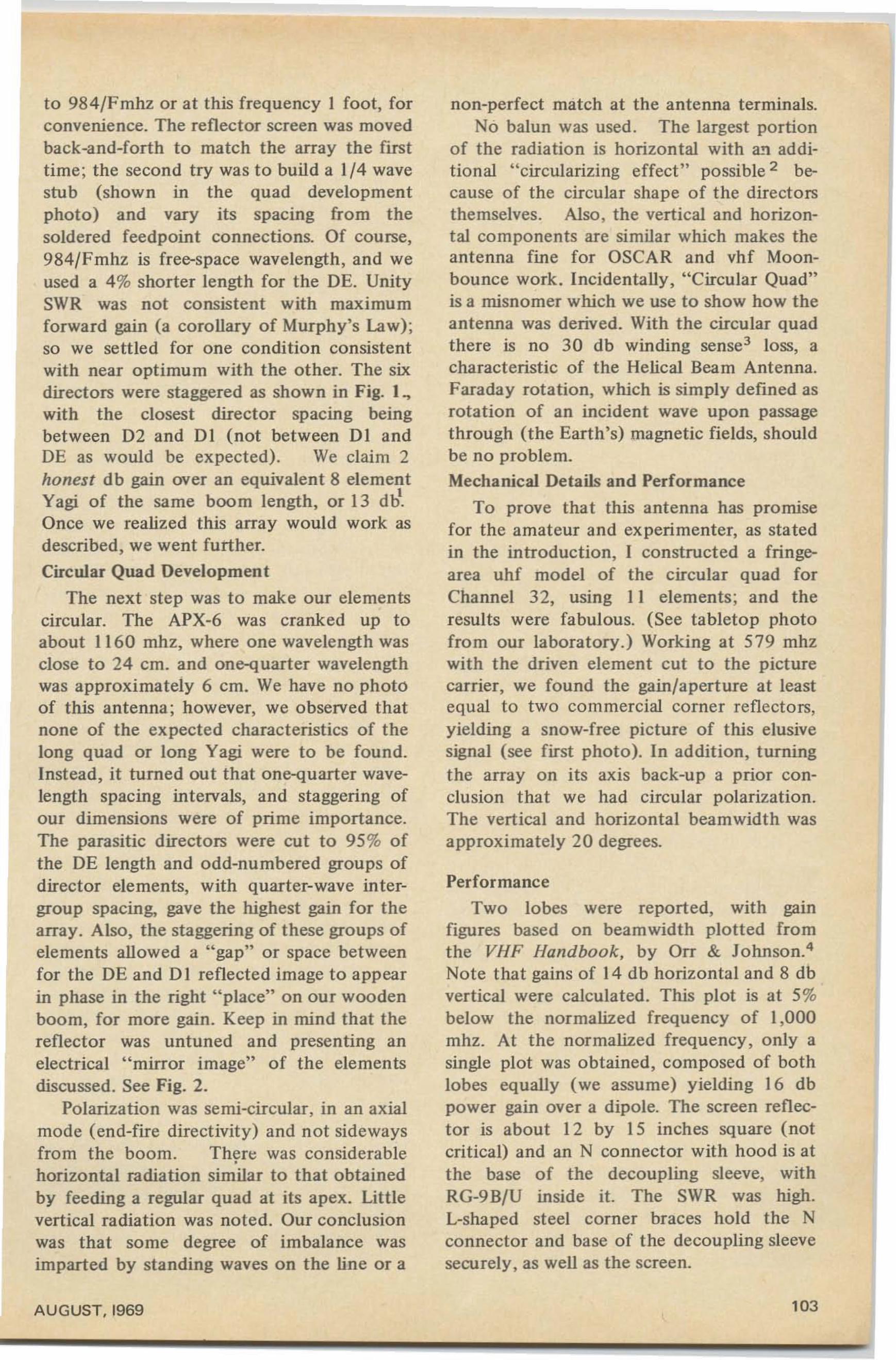
to 984/Fmhz or at this frequency I foot, forconvenience. The reflector screen was movedback-and-forth to match the array the firsttime; the second try was to build a 1/4 wavestub (shown in the quad developmentphoto) and vary its spacing from thesoldered feedpoint connections. Of course,984/Fmhz is free-space wavelength, and weused a 4% shorter length for the DE. UnitySWR was not consistent with maximumforward gain (a corollary of Murphy's Law);so we settled for one condition consistentwith near optimum with the other. The sixdirectors were staggered as shown in Fig. 1~with the closest director spacing beingbetween D2 and DI (not between DI andDE as would be expected). We claim 2honest db gain over an equivalent 8 elementYagi of the same boom length, or 13 dl1.Once we realized this array would work asdescribed, we went further.
Circular Quad Development
The next step was to make our elementscircular. The APX-6 was cranked up toabout 1160 mhz, where one wavelength wasclose to 24 cm. and one-quarter wavelengthwas approximately 6 ern. We have no photoof this antenna; however, we observed thatnone of the expected characteristics of thelong quad or long Yagi were to be found.Instead, it turned out that one-quarter wavelength spacing intervals, and staggering ofour dimensions were of prime importance.The parasitic directors were cut to 95 % ofthe DE length and odd-numbered groups ofdirector elements, with quarter-wave intergroup spacing, gave the highest gain for thearray. Also, the staggering of these groups ofelements allowed a "gap" or space betweenfor the DE and DI reflected image to appearin phase in the right "place" on our woodenboom, for more gain. Keep in mind that thereflector was untuned and presenting anelectrical "mirror image" of the elementsdiscussed. See Fig. 2.
Polarization was semi-circular, in an axialmode (end-fire directivity) and not sidewaysfrom the boom. There was considerable•horizontal radiation similar to that obtainedby feeding a regular quad at its apex. Littlevertical radiation was noted. Our conclusionwas that some degree of imbalance wasimparted by standing waves on the line or a
AUGUST,I969
non-perfect match at the antenna terminals.No balun was used . The largest portion
of the radiation is horizontal with an additional "circularizing effect" possible 2 because of the circular shape of the directorsthemselves. Also, the vertical and horizontal components are similar which makes theantenna fine for OSCAR and vhf Moonbounce work. Incidentally, "Circular Quad"is a misnomer which we use to show how theantenna was derived. With the circular quadthere is no 30 db winding sense! loss, acharacteristic of the Helical Beam Antenna.Faraday rotation, which is simply defined asrotation of an incident wave upon passagethrough (the Earth's) magnetic fields, shouldbe no problem.Mechanical Details and Performance
To prove that this antenna has promisefor the amateur and experimenter. as statedin the introduction, I constructed a fringearea uhf model of the circular quad forChannel 32, using II elements; and theresults were fabulous. (See tabletop photofrom our laboratory.) Working at 579 mhzwith the driven element cut to the picturecarrier, we found the gain/aperture at leastequal to two commercial corner reflectors,yielding a snow-free picture of this elusivesignal (see first photo). In addition, turningthe array on its axis back-up a prior conclusion that we had circular polarization.The vertical and horizontal beamwidth wasapproximately 20 degrees.
Performance
Two lobes were reported, with gamfigures based on beamwidth plotted fromthe VHF Handbook, by Orr & Johnson.'Note that gains of 14 db horizontal and 8 dbvertical were calculated. This plot is at 5%below the normalized frequency of 1,000mhz. At the normalized frequency, only asingle plot was obtained, composed of bothlobes equally (we assume) yielding 16 dbpower gain over a dipole. The screen reflector is about 12 by 15 inches square (notcritical) and an N connector with hood is atthe base of the decoupling sleeve, withRG-9B/U inside it. The SWR was high.L-shaped steel corner braces hold the Nconnector and base of the decoupling sleevesecurely. as well as the screen.
t03
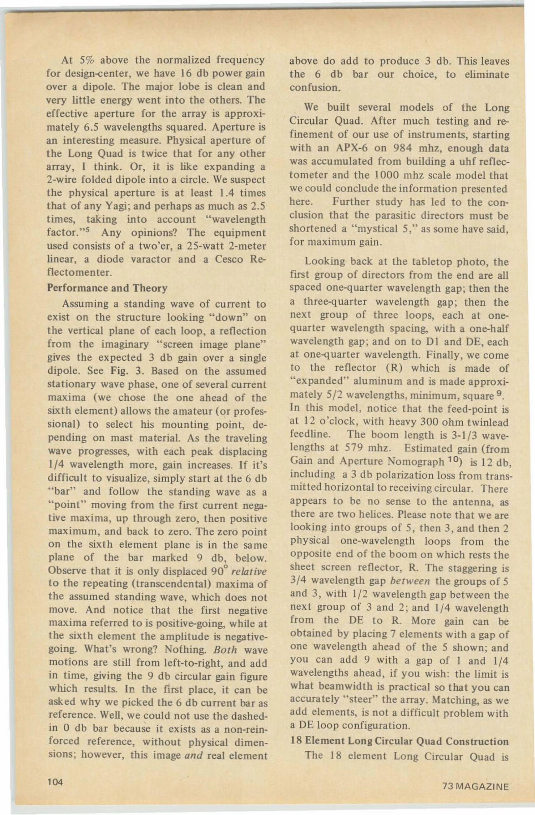
At 5% above the normalized frequencyfor design-center, we have 16 db power gainover a dipole. The major lobe is clean andvery little energy went into the others. Theeffective aperture for the array is approximately 6.5 wavelengths squared. Aperture isan interesting measure. Physical aperture ofthe Long Quad is twice that for any otherarray, I think. Or, it is like expanding a2-wire folded dipole into a circle. We suspectthe physical aperture is at least 1.4 timesthat of any Yagi; and perhaps as much as 2.5times, taking into account "wavelengthfactor. "5 Any opinions? The equipmentused consists of a two'er, a 25-watt 2-meterlinear, a diode varactor and a Cesco Reflectornenter.
Performance and Theory
Assuming a standing wave of current toexist on the structure looking "down" onthe vertical plane of each loop, a reflectionfrom the imaginary "screen image plane"gives the expected 3 db gain over a singledipole. See Fig. 3. Based on the assumedstationary wave phase, one of several currentmaxima (we chose the one ahead of thesixth element) allows the amateur (or professional) to select his mounting point, depending on mast material. As the travelingwave progresses, with each peak displacing1/4 wavelength more, gain increases. If it'sdifficult to visualize, simply start at the 6 db"bar" and follow the standing wave as a"point" moving from the first current negative maxima, up through zero, then positivemaximum, and back to zero. The zero pointon the sixth element plane is in the sameplane of the bar marked 9 db, below.Observe that it is only displaced 90° relativeto the repeating (transcendental) maxima ofthe assumed standing wave, which does notmove. And notice that the first negativemaxima referred to is positive-going, while atthe sixth element the amplitude is negativegoing. What's wrong? Nothing. Both wavemotions are still from left-to-right, and addin time, giving the 9 db circular gain figurewhich results. II! the first place, it can beasked why we picked the 6 db current bar asreference. Well, we could not use the dashedin 0 db bar because it exists as a non-reinforced reference, without physical dimensions; however, this image and real element
104
above do add to produce 3 db. This leavesthe 6 db bar our choice, to eliminateconfusion.
We built several models of the LongCircular Quad. After much testing and refinement of our use of instruments, startingwith an APX-6 on 984 mhz, enough datawas accumulated from building a uhf reflectometer and the 1000 mhz scale model thatwe could conclude the information presentedhere. Further study has led to the conclusion that the parasitic directors must beshortened a "mystical 5," as some have said,for maximum gain.
Looking back at the tabletop photo, thefirst group of directors from the end are allspaced one-quarter wavelength gap; then thea three-quarter wavelength gap; then thenext group of three loops, each at onequarter wavelength spacing, with a one-halfwavelength gap; and on to DI and DE, eachat one-quarter wavelength. Finally, we cometo the reflector (R) which is made of"expanded" aluminum and is made approximately 5/2 wavelengths, minimum , square 9 .
In this model, notice that the feed-point isat 12 o'clock, with heavy 300 ohm twinleadfeedline. The boom length is 3-1 /3 wavelengths at 579 mhz. Estimated gain (fromGain and Aperture Nomograph' 0) is 12 db,including a 3 db polarization loss from transmitted horizontal to receiving circular. Thereappears to be no sense to the antenna as,there are two helices. Please note that we arelooking into groups of 5, then 3, and then 2physical one-wavelength loops from theopposite end of the boom on which rests thesheet screen reflector, R. The staggering is3/4 wavelength gap between the groups of 5and 3, with 1/2 wavelength gap between thenext group of 3 and 2; and 1/4 wavelengthfrom the DE to R. More gain can beobtained by placing 7 elements with a gap ofone wavelength ahead of the 5 shown; andyou can add 9 with a gap of I and 1/4wavelengths ahead, if you wish: the limit iswhat beamwidth is practical so that you canaccurately "steer" the array. Matching, as weadd elements, is not a difficult problem witha DE loop configuration.
18 Element Long Circular Quad ConstructionThe 18 element Long Circular Quad is
73 MAGAZINE
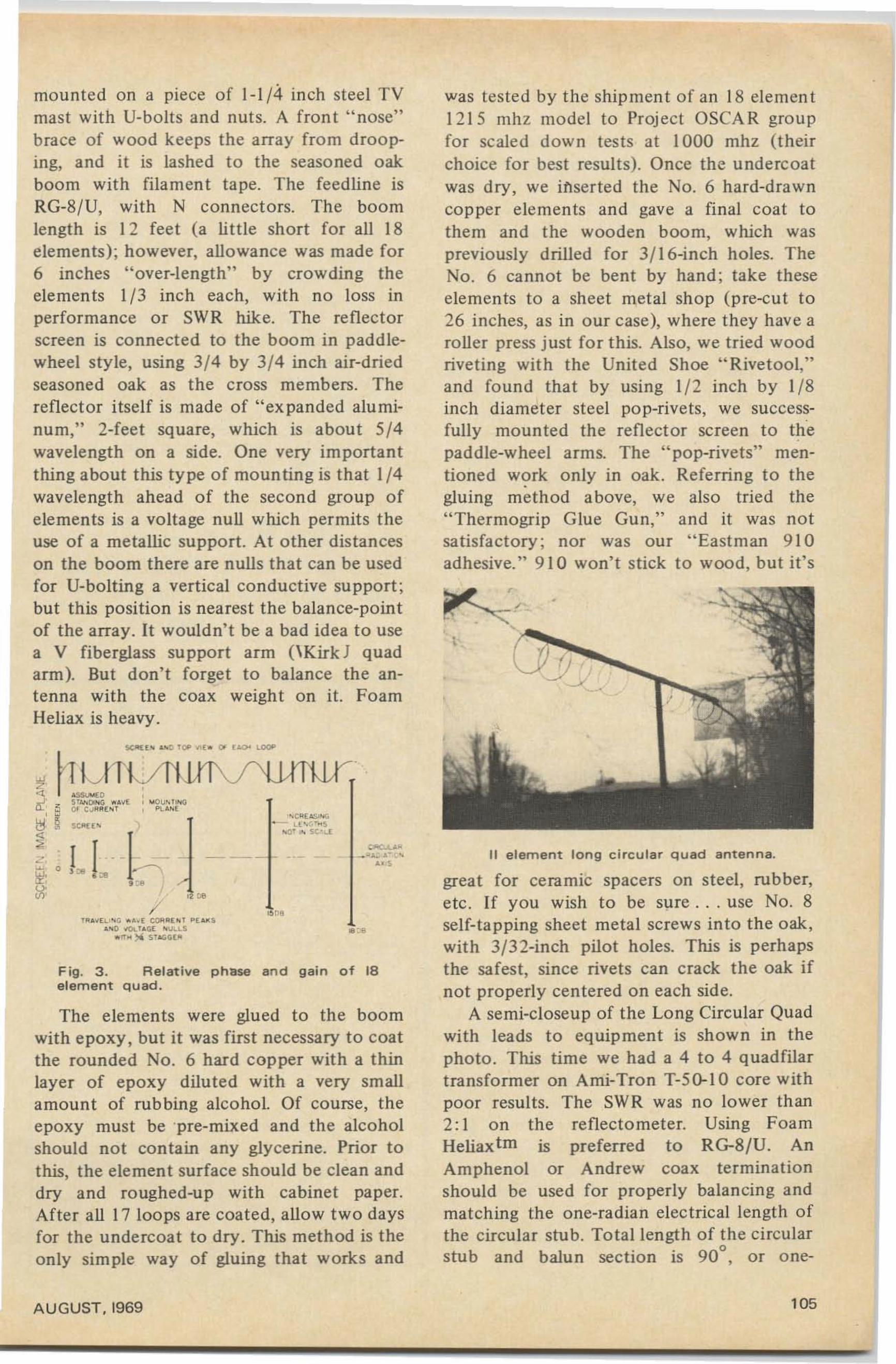
Fig. 3. Relative phase and gain of 18element quad.
The elements were glued to the boomwith epoxy, but it was first necessary to coatthe rounded No. 6 hard copper with a thinlayer of epoxy diluted with a very smallamount of rubbing alcohol. Of course, theepoxy must be 'pre-mixed and the alcoholshould not contain any glycerine. Prior tothis , the element surface should be clean anddry and roughed-up with cabinet paper.After all 17 loops are coated, allow two daysfor the undercoat to dry. This method is theonly simple way of gluing that works and
II element long circular quad antenna.
was tested by the shipment of an 18 element1215 mh z model to Project OSCAR groupfor scaled down tests at 1000 mhz (theirchoice for best results). Once the undercoatwas dry, we inserted the No.6 hard-drawncopper elements and gave a final coat tothem and the wooden boom, which waspreviously drilled for 3fl6-inch holes. TheNo. 6 cannot be bent by hand; take theseelements to a sheet metal shop (pre-cut to26 inches, as in our case), where they have aroller press just for this. Also. we tried woodriveting with the United Shoe "Rivetool,"and found that by using 1/2 inch by 1/8inch diameter steel pop-rivets, we successfully mounted the reflector screen to thepaddle-wheel arms. The "pop-rivets" mentioned work only in oak. Referring to the
•gluing method above, we also tried the"Therrnogrip Glue Gun," and it was notsatisfactory ; nor was our "Eastman 910adhesive." 910 won't stick to wood, but it's
great for ceramic spacers on steel, rubber,etc . If you wish to be sure .. . use No. 8self-tapping sheet metal screws into the oak,with 3/32-inch pilot holes. This is perhapsthe safest. since rivets can crack the oak ifnot properly cen tered on each side.
A semi-closeup of the Long Circular Quadwith leads to equipment is shown in thephoto. This time we had a 4 to 4 quadfilartransformer on Ami-Tron T-5~1 0 core withpoor results. The SWR was no lower than2: 1 on the reflectometer, Using FoamHeliaxtm is preferred to RG-8/U. AnAmphenol or Andrew coax terminationshould be used for properly balancing andmatching the one-radian electrical length ofthe circular stub. Total length of the circularstub and balun section is 90°. or one-
.~
' ~'~£ ~I""• L [ .. '· .... S
~O' .. st"Ll
/
!:-,--...'A ~' E c ''' ~ " b E eOARI ... Pl_S
'''0 oIOL U GE " ~LL S
..,, ~ ~ s·...'a·
mounted on a piece of 1-1/4 inch steel TVmast with U-bolts and nuts. A front "nose"brace of wood keeps the array from drooping. and it is lashed to the seasoned oakboom with filament tape. The feedline isRG-8/U, with N connectors. The boomlength is 12 feet (a little short for all 18elements); however, allowance was made for6 inches "over-length" by crowding theelements 1/3 inch each, with no loss inperformance or SWR hike. The reflectorscreen is connected to the boom in paddlewheel style, using 3/4 by 3/4 inch air-driedseasoned oak as the cross members. Thereflector itself is made of "expanded aluminum," 2-feet square, which is about 5/4wavelength on a side. One very importantthing about this type of mounting is that 1/4wavelength ahead of the second group ofelements is a voltage null which permits theuse of a metallic support. At other distanceson the boom there are nulls that can be usedfor U-bolting a vertical conductive su pport ;but this position is nearest the balance-pointof the array. It wouldn't be a bad idea to usea V fiberglass support arm (\Kirk ] quadarm). But don't forget to balance the antenna with the coax weight on it. FoamHeliax is heavy.
AUGUST,1969 105
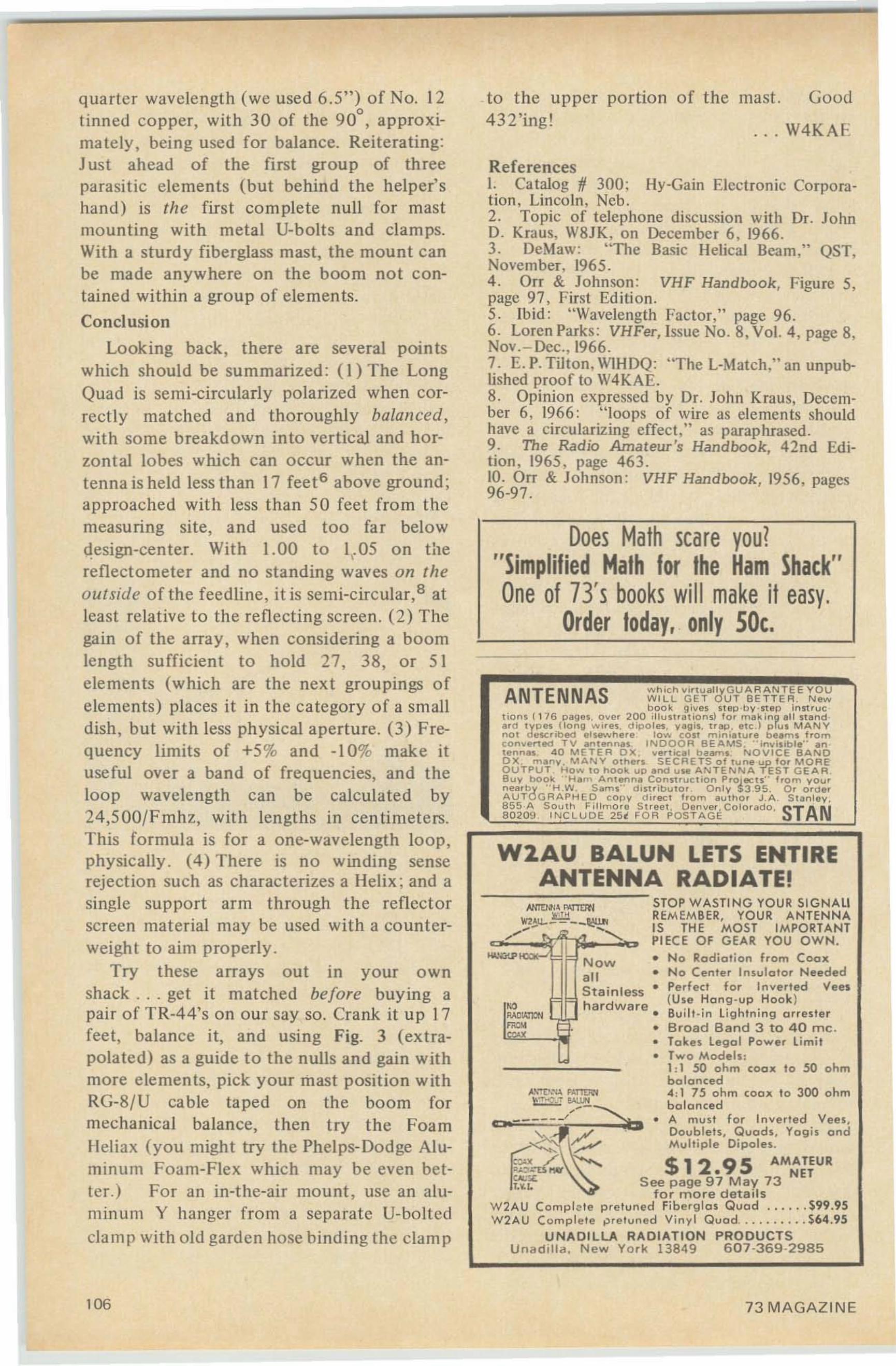
W2.AU BALUN LETS ENTIREANTENNA RADIATE!
Does Math scare you?"Simplified Math for the Ham Shack"One of 73's books will make it easy,
Order today, only SOc.
ANTENNAS whichvi.tuall yGUA R A NTE E YO UW I LL GE T OU T BE T TER. N ewbook gives step·by· st ep in st ruc
tion$« 1 76 p ages, over 200 iHust ra ti.ons) for ma king a ll n a nd ·a rd types (Ionll ,,,,,res. dipoles. yall's, t <ap , etc,) p[us MAN Ynot d ..seribed elsewhere low eost miniatu re beams b o mconve"ed TV antennas. INDOOR BEAMS , " inv is ib le ' · antenn.., 4 0 METER ox , vertical ba..,.." NOVICE BANDOX, many . MANY othe'S. SECRETS of tune up for MORE'OUTPUT , HO .... to hook UP and uH ANTENNA TEST GEAR.Buy bOOk ··Ham Antenna COnstruction P roJects'· from vou,nearby "H.W. S"ms·' d,st ributor Only $3,95. 0 , O'de<AUTOGRAPHED COflY di rec t h o m au tho. J.A. Stanley,855 A 50uth Fillmore Street. Oenve"Colorado, STAN8 0209 INCLUDE 25t FOR P O S T A G E
Good
. . . W4KAE
portion of the mast.
STOP WASTING YOUR SIGNAL!REM EMB ER, YOUR AN TEN N AIS THE MOSr IMPO RTANTPIECE O F GEAR YOU OWN,
Now • No Radiat io n from Coaxall • No Center Insulot or NeededStainless • Perfect for Inverted 'Vees
I-iO l=lb h a r d w a re (Use Ho ng -up Hook )AAtloll'Pl ,'-,!!II,... . Buil t -in Li g htnin g a rreste r~ Ft • Broad Band 3 to 40 me,
l)• rakes legal Power limit• Two Mod els :
I :1 50 ohm COOl( to 50 ohmbalanced
A\'T ~ F~nm-l 4 : I 75 ohm coax to 300 ohm" ~ - !AU."!... - -...... b a la nced
CO ------/ ~ • A mu st fo r Inverted Vees,~~=JI': ~.:.,. .. Doublets, Quad s. Yog is and....""'">, ~. Multiple Oipoles,
~~. / ~ $12 9S AMATEU R~~:omrw' • NET~C '- See page 97 May 73
'" fo r more deta i lsW2AU Complete pretoned Fib e.g la s Quad , $99,95W2AU CQmpl ele ~ reluned Vinyl Quod " .. $64.95
UNADI LLA RADIATION PRODUCTSU n ad i l l a . N ew York 13849 607-369·2985
References1. Catalog fI 300: Hy-Gain Electronic Corporation , Lincoln, Ncb.2. Topic of telephone discussion with Dr. JohnD. Kraus, W8JK, on December 6. 1966.3. DeMaw: "The Basic Helical Beam," QST,November, 1965.4. Orr & Johnson : VHF Handbook, Figure 5,page 97 , F'irst Edition.5. Ibid : "Wavelength Factor," page 96.6 . Loren Parks: VHFer, Issue No.8, Vol. 4, page 8,Nov.-Dec., 1966.7. E. P. Tilton , WIHDQ: 'T he L-Match." an unpublished proof to W4KAE.8. Opinion expressed by Dr. John Kraus, December 6, 1966: "loops of wire as clements shouldhave a circularizing effect." as paraphrased.9. The Radio Amateur 's Handbook, 42nd Edition , 1965, page 463.10. Orr & Johnson: VHF Handbook, 1956, pages96-97 .
to the u pper432'ing!
quarter wavelength (we used 6 .5") of No. 12tinned co pper. with 30 of the 90°, approximately , being used for balance. Reiterating:Just ahead of the first group of threeparasitic clements (but behind the helper'shand ) is the firs t complete null for mastmounting with metal Usbolts and clamps.With a sturdy fiberglass mast, the mount canbe made anywhere on the boom not contained within a group of elemen ts.
Concl usion
Looking back, there are several pointswhich should be summarized: (I) The Lo ngQuad is semi-circularly polarized when correctly matched and thoroughly balanced,with some breakdown into vertical and horzontal lobes which can occur when the antenna is held less than 17 feet G above ground ;approached with less than 50 feet fro m themeasuring site, and used too fa r belowdesign-center. With 1.00 to 1\.05 on thereflectometer and no standing waves on theoutside of the feed line , itis semi-circular.P atleast relative to the reflecti ng screen . (2) Thegain of the array. when considering a boomlength su fficient to hold 27, 38, or 5 1elements (which are the next groupings ofelements) places it in t he category of a smalldish, but with less physical aperture. (3) Frequency limits of +5 % and -10% make ituseful over a band of frequencies, and theloop wavelength can be calcula ted by24,500/Fmhz, with lengths in cen timeters.This formula is for a one-wavelength loop,physically . (4) There is no winding senserejection such as characterizes a Helix ; and asingle support arm through the reflecto rscreen material may be used with a co unte rweight to aim properly .
Try these arrays out in your ownshack . .. get it matched before buying apair of TR-44's on our say so. Crank it up 17feet, balance it, and usi ng Fig. 3 (extrapolated) as a guide to the nulls and gain withmore elements, pick your mast position withRG-8 /U cable taped on the boom formechanical balance, then try the FoamHeliax (you might try the Phelps-Dodge Aluminum Foam-Flex which may be even better.) For an in-the-air mount , use an aluminum Y hanger from a separate U-bol tcdclamp with old garden hose bindi ng the clamp
106 73 MAGAZ INE
(continued from page 2)
trend in amateur licenses. Nothing was doneabout setting up a small office in Washingtonfor someone. even on part time, to lobby inCongress for our hobby. A second meetingis scheduled for November this year. sothose few amateurs who are interested intheir hobby have another chance this year toget the directors of the League to get offdead center.
There goes Wayne again, lambasting theLeague! No, I'm not anti-ARRL at all,only pro-amateur radio. All of you have putyour eggs in one single basket : the ARRL.If there are any reasons whatever for amateurradio not paying for some national publicityI would welcome them and give them spacein 73. If there are any reasons why amateurradio should have fewer amateurs instead ofmore I would like to know what they are. Iknow a lot of reasons why we should havemore amateurs and why we need publicityand need it desperately, but I sure have ye tto hear anyone speak up in QST or anywhereelse and give reasons why we should not tryto grow.
Along the same line, I have heard manyreasons why amateur radio should have aworking lobby in Washington, but I have yetto hear a single reason against it . Yet yearafter year we don't have one. Will someone.anyone. please write an article for 73 explaining why amateur radio should be the onlyradio service with no protection in Washington?
What did the directors accomplish? Well,for one thing they decided to petition theFCC to open the 29 .5-29.7 band to Techs.We do need more activity up there, no question about it . Perhaps, since the only realdifference between the Tech and the Generallicense is a matter of code speed, this is thebreak-through that Techs have been waitingfor and which will eventually get them a foothold on all our lower bands. [wouldthink that there might be a survey taken toascertain the activities of the Techs. Howmany of the active amateurs o n 1296 areTechs? What percentage and how many on432? On 220? On two meters? On six?There are some 60,000 Techs today. I thinkwe should know how many are active. andwhat bands they are using at present. If we
AUGUST, 1969
open ten will it siphon off everyone fromsix meters? Or will it just make for moreactivity in total?
The directors directed the ARRL to pe tition the FCC to open the remainder of twometers to Techs. This is long overdue, as Imentioned in an editorial several years back.I don't know why no Tech has taken t heeffort to petit ion the FCC for this change.This would integrate the band and eliminatethe second-class citizen fee lings of Techs whohear the Generals working aurora, CW. contests and satellites down on the low end ofthe band, unable to really join in the fun .
They directed the League to petition theFCC to reduce the waiting period for ExtraClass to one year from two. This is probablya good idea too, but I doubt if it will havemuch effect on the massive resistance to theExtra Class we have seen so far.,
They directed QST to start publishing infoon VHF repeaters, put out a booklet on thesubject, and get it into the Handbook. Great,but why was a board directive needed to getQST to this important phase of our hobby?
The $100,000 fund for amateur radio promotion worldwide was refunded . Excellent,But am I being rotten to suggest that so me ofthe members may be interested in accountingof funds already spent? Nothing whateverhas been published that I recall seeing. Wherethere is secrecy there is usually a good reasonfor it. Or does anyone else care where themoney is going?
Dialog in 73?
Though I have written quite a few pro-•
vocative editorials down through the years,I have had few letters as a result that wereworthy of publishing. Sometimes I wonderif there is anyone out there. Isn't there anyone that has the hankering to write an editorial among our readership?
How about opening ' 3650 - 3700 forphone operation? I would suggest 3750 3800, but then the ten Canadian phonestat ions that operate in that band would getall upset and descend on me as a newly borndevil. No, let's leave t hose VE lads their ownprivate perserve to sit and talk with theirown and QRM the hapless European andAfrican stations that try to work through tothe U.S. How about a nice phone band
107
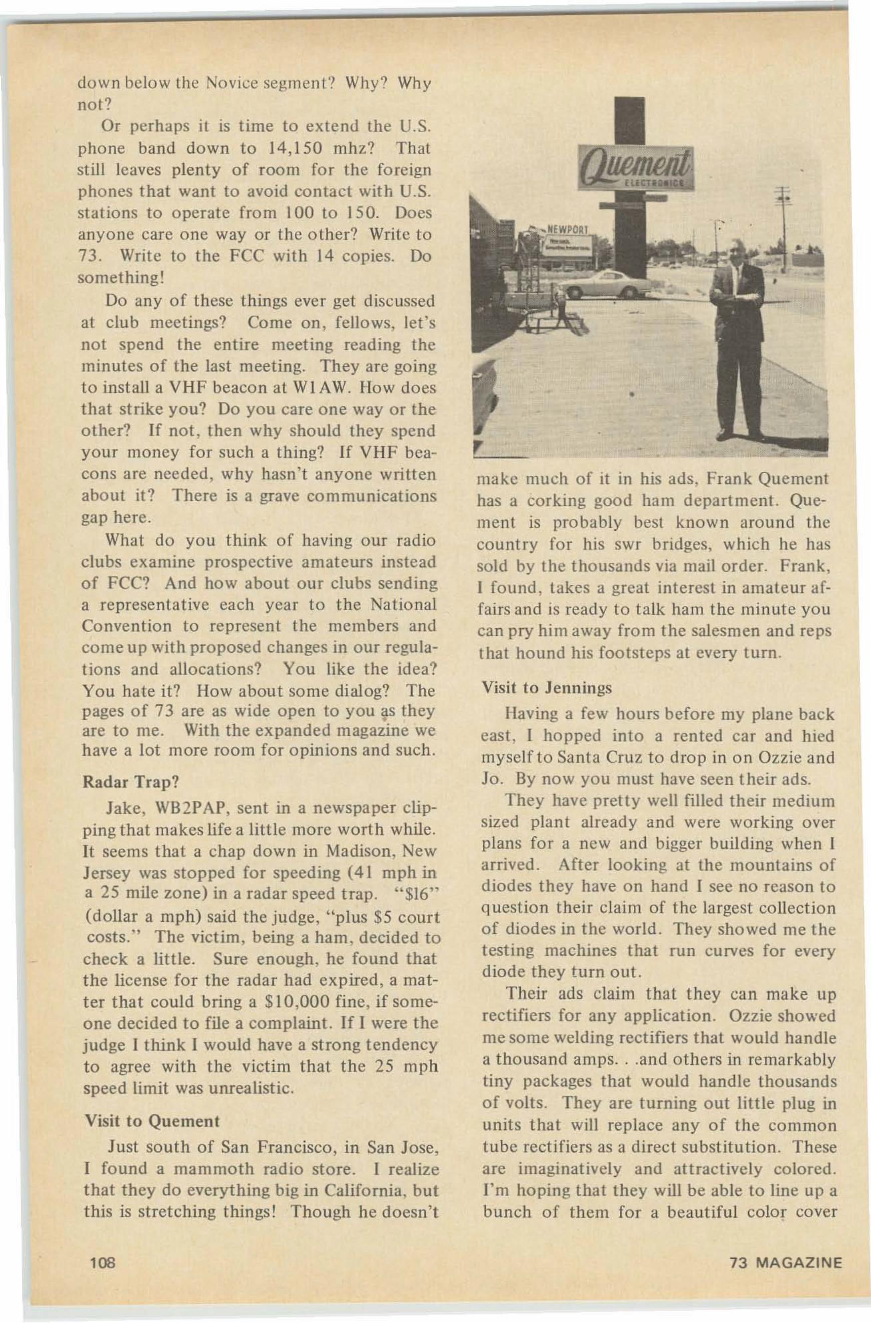
down below the Novice segment? Why? Whynot?
Or perhaps it is time to extend the U.S.pho ne band down to 14, 150 mhz? Thatsti ll leaves plenty of room for the foreignphones that want to avoid contact with U.S.stations to operate from 100 to 150. Doesanyone care one way or the o ther? Write to73. Write to the FCC with 14 copies. Dosomething!
Do any of these things ever get discussedat club mee tings? Come on, fellows, let'snot spend the entire meeting reading theminutes of the last meeti ng. They are goingto install a VHF beacon at WI AW. How doesthat strike you? Do you care one way or theother? If not, then why should they spendyour money for such a thing? If VHF beacons are needed, why hasn' t anyone writtenabout it? There is a grave communicationsgap here.
What do you think of having our radioclubs examine prospective amateurs insteadof FCC? And how about our clubs sendinga representat ive each year to the NationalConvention to represent the members andcome up with proposed changes in our regulations and allocations? You like the idea?You hate it? How about some dialog? Thepages of 73 are as wide open to you ~s theyare to me. With the expanded magazine wehave a lot more room for opinio ns and such.
Radar Trap?
Jake, WB2PAP, sent in a newspaper clipping that makes life a little more wort h while .It seems that a chap down in Madison, NewJersey was stopped for speeding (41 mph ina 25 mile zone) in a radar speed t rap. "$16"(dollar a mph) said the judge, " plus $5 courtcosts:' The victim, being a ham, decided tocheck a little. Sure enough, he found thatthe license for the radar had expired, a matt er that could bring a $10,000 fine, if someone decided to file a complaint. If I were thejudge I think I would have a strong tendencyto agree with the victim that the 25 mphspeed limit was unrealistic.
Visit to Quement
Just south of San Francisco, in San Jose,I found a mammoth radio store. I realizet hat they do everything big in California. butthis is stretching things I Though he doesn't
108
make much of it In his ads, Frank Quementhas a corking good ham department. Quement is probably best known around thecountry for his swr bridges, which he hassold by the thousands via mail order. Frank,I found , takes a great interest in amateur affairs and is ready to talk ham the minute youcan pry him away from the salesmen and repsthat hound his footsteps at every turn.
Vis it to Jennings
Having a few hours before my plane backcast, I hopped into a rented car and hiedmyself to Santa Cruz to drop in on Ozzie andJo . By now you must have seen their ads.
They have pretty well filled their mediumsized plant already and were working overplans for a new and bigger building when Iarrived . After looking at the mountains ofdiodes they have on hand I see no reason toquestion the ir claim of the largest collectionof diodes in the world. They showed me thetesting machines that run curves for everydiode they turn out.
Their ads claim that they can make uprectifiers for any application. Ozzie showedme some welding rectifiers that would handlea thousand amps...and ot hers in remarkablytiny packages that wo uld hand le tho usandsof volts. They are turning out little plug inunits that will replace any of the commontube rectifiers as a direct substitut ion . Theseare imaginatively and attractively colored .I' m hoping that they will be ab le to line up abunch of them for a beautiful color cover
73 MA GAZINE
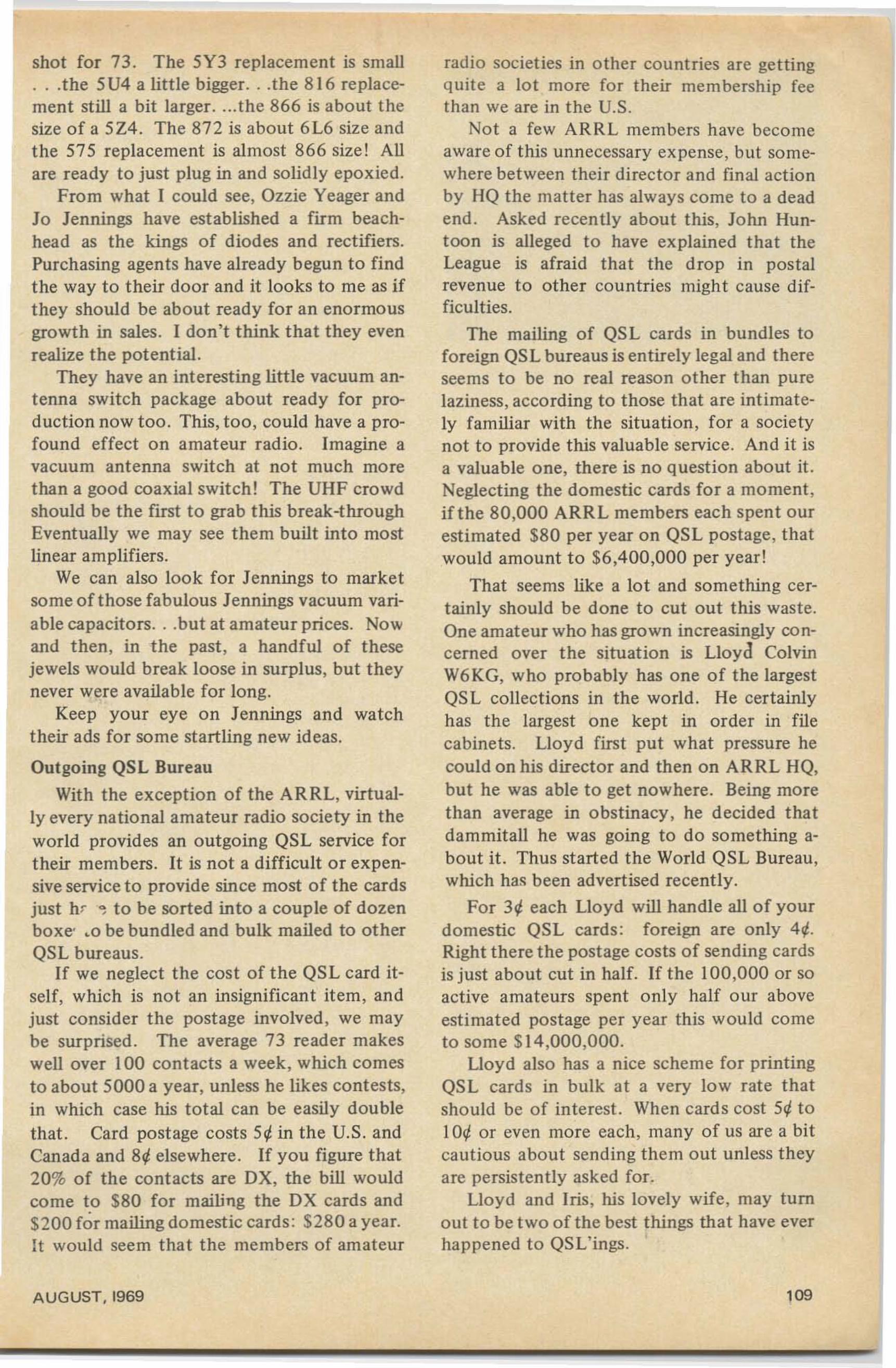
shot for 73. The 5Y3 replacement is small.. .the 5U4 a little bigger.. .the 8 16 replacement still a bit larger.... the 866 is about thesize of a 5Z4. The 872 is about 6L6 size andthe 575 replacement is almost 866 size! Allare ready to just plug in and solid ly epoxied.
From what I could see, Ozzie Yeager andJo Jennings have established a firm beachhead as the kings of diodes and rectifiers.Purchasing agents have already begun to findthe way to their door and it looks to me as ifthey should be about ready for an enormousgrowth in sales. I don't think that they evenrealize the potential.
They have an interesting little vacuum antenna switch package about ready for production now too . This, too, could have a profound effect on amateur radio. Imagine avacuum antenna switch at not much morethan a good coaxial switch! The UHF crowdshould be the first to grab this break-throughEventually we may see them built into mostlinear amplifiers.
We can also look for Jennings to marketsome of those fabulous Jennings vacuum variable capacitors...but at amateur prices. Nowand then, in the past, a handful of thesejewels would break loose in surplus, but theynever were available for long.
Keep your eye on Jennings and watchtheir ads for some startling new ideas.
Outgoing QSL Bureau
With the exception o f the ARRL, virtually every national amateur radio society in theworld provides an outgoing QSL service fortheir members. It is not a difficult or expensive service to provide since most of the cardsjust hr , to be sorted into a couple of dozenboxe: ,0 be bundled and bulk mailed to otherQSL bureaus.
If we neglect the cost of the QSL card itself, which is not an insignificant item, andjust consider the postage involved . we maybe surprised. The average 73 read er makeswell over 100 contacts a week , which comesto about 5000 a year, unless he likes contests,in which case his total can be easily doublethat. Card postage costs 5¢ in the U.S. andCanada and 8¢ elsewhere. If you figure that20% of the contacts are DX, the bill wouldcome to $80 for mailing the DX cards and$200 for mailing domestic cards : $280 a year.It would seem that the members o f amateur
AUGUST, 1969
radio societies in o ther countries are gettingquite a lot more fo r their membership feethan we are in the U.S.
Not a few ARRL members have becomeaware of this unnecessary expense, but somewhere between their director and final actionby HQ the matter has always come to a deadend . Asked recently about this, John Hunt oon is alleged to have explained that theLeague is afraid that the drop in postalrevenue to other countries migh t cause difficulties .
The mailing of QSL cards in bundles toforeign QSL bureaus is entirely legal and thereseems to be no real reason other than purelaziness, according to those that are intimately familiar with the situation, for a societynot to provide this valuable service . And it isa valuable one, there is no question about it.Neglecting the domestic cards for a moment,if the 80,000 ARRL members each spent ourestimated $80 per year on QSL postage, thatwould amount to $6,400,000 per year!
That seems like a lot and something certainly should be done to cut out this waste.One amateur who has grown increasingly concerned over the situat ion is Lloyd ColvinW6KG, who probably has one of the largestQSL collections in the world. He certainlyhas the largest one kept in order in filecabinets. Lloyd first put what pressure hecould on his director and then on ARRL HQ,but he was able to get nowhere. Being morethan average in obstinacy, he decided thatdammitall he was going to do something about it. Thus started the World QSL Bureau,which has been advertised recently.
For 3¢ each Lloyd will handle all of yourdomestic QSL cards : foreign are only 4 ¢.Right there the postage costs of sending cardsis just about cut in half. If the 100,000 or soactive amateurs spent only half our aboveestimated postage per year this would cometo some $14,000,000.
Lloyd also has a nice scheme for print ingQSL cards in bulk at a very low rate thatshould be of interest. When cards cost 5¢ toIO¢ or even more each, many of us are a bitcautious about sending them out unless theyare persistently asked for.
Lloyd and Iris, his lovely wife, may turnout to be t wo of the best things that have everhappened to QSL'ings.
109
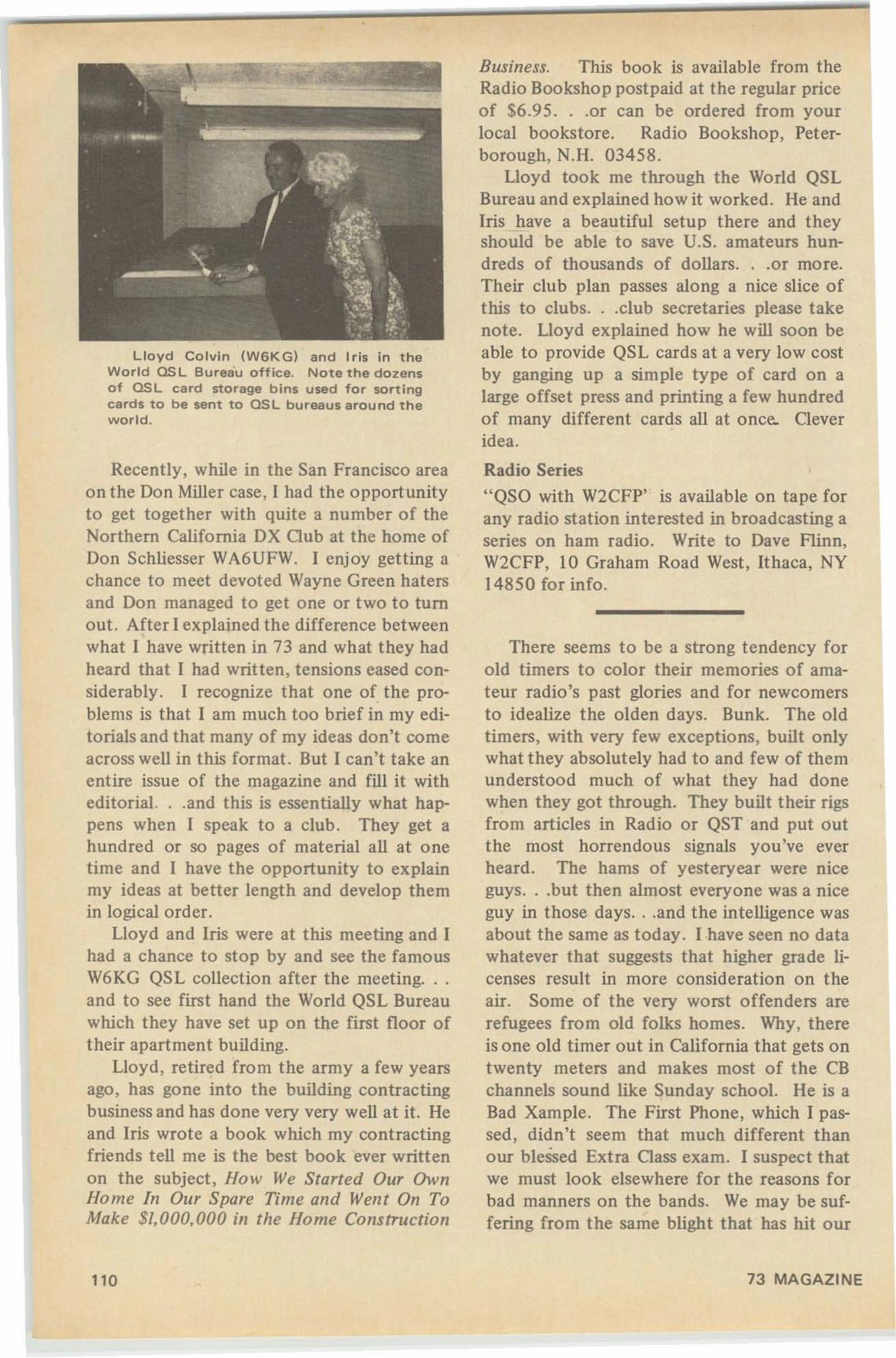
Lloyd Colvin (W6KG) and Iris in theWorld OS L Bureau office. Note the dozensof OSL card storage bins used for sortingcards to be sent to QSL bureaus around theworld .
Recently, while in the San Francisco areaon the Don Miller case, I had the opportunityto get together with quite a number of theNorthern California DX Club at the home ofDon Schliesser WA6UFW. I enjoy getting achance to meet devoted Wayne Green hatersand Don managed to get one or two to tumout. After I explained the difference betweenwhat I have written in 73 and what they hadheard that I had written , tensions eased considerably. I recognize that one of the problems is that I am much too brief in my editorials and that many of my ideas don't comeacross well in this format. But I can't take anentire issue of the magazine and fill it witheditorial. ..and this is essentially what happens when I speak to a club . They get ahundred or so pages of material all at onetime and I have the opportunity to explainmy ideas at better length and develop themin logical order.
Lloyd and Iris were at this meeting and Ihad a chance to stop by and see the famousW6KG QSL collection after the meeting. . .and to see first hand the World QSL Bureauwhich they have set up on the first floor oftheir apartment building.
Lloyd, retired from the army a few yearsago, has gone into the building contractingbusiness and has done very very well at it. Heand Iris wrote a book which my contractingfriends tell me is the best book ever writtenon the subject, How We Started Our OwnHome In Our Spare Time and Went On ToMake $/.000.000 in the Home Construction
110
Business. This book is available from theRadio Bookshop postpaid at the regular priceof $6 .95...or can be ordered from yourlocal bookstore. Radio Bookshop, Peterborough, N.H. 03458.
Lloyd took me through the World QSLBureau and explained how it worked . He andIris have a beautiful setup there and theyshould be able to save U.S. amateurs hundreds of thousands of dollars...or more.Their club plan passes along a nice slice ofthis to clubs...club secretaries please takenote. Lloyd explained how he will soon beable to provide QSL cards at a very low costby ganging up a simple type of card on alarge offset press and printing a few hundredof many different cards all at once.. Cleveridea.
Radio Series
"QSO with W2CFP' is available on tape forany radio station interested in broadcasting aseries on ham radio. Write to Dave Flinn,W2CFP, 10 Graham Road West, Ithaca, NY14850 for info.
There seems to be a strong tendency forold timers to color their memories of amateur radio's past glories and for newcomersto idealize the olden days. Bunk. The oldtimers, with very few exceptions, built onlywhat they absolutely had to and few of themunderstood much of what they had donewhen they got through. They built their rigsfrom articles in Radio or QST and put outthe most horrendous signals you've everheard. The hams of yesteryear were niceguys...but then almost everyone was a niceguy in those days. . .and the intelligence wasabout the same as today. I have seen no datawhatever that suggests that higher grade licenses result in more consideration on theair. Some of the very worst offenders arerefugees from old folks homes. Why, thereis one old timer out in California that gets ontwenty meters and makes most of the CBchannels sound like Sunday school. He is aBad Xample. The First Phone, which I passed, didn't seem that much different thanour blessed Extra Class exam. I suspect thatwe must look elsewhere for the reasons forbad manners on the bands. We may be suffering from the same blight that has hit our
73 MAGAZINE
.. .Wayne
schools, our cities, and our whole society.This seems to be a world-wide phenomenon,and seems worth so me st udy. Can we blameSpack? The bomb? Or sunspots?
FLASH!Navassa is open for business again.The State Department informed us that
henceforward any and all amateurs in teres tedin visiting Navassa may do so, provided theyobtain prior permission from the Coast Guard.This permission will be given if you can assure them that you will not require rescue.
I suppose that someone will rush rightdown there and take care of the need thathas built up since a few of us operated fromthere back about ten years ago. I sure wouldlike to get myoid KC4AF call back again andget on for a few days from there. Perhaps weshould work up a giant DXpedition o f allthose interested in going and go down enmasse?
Homebrew GenealogyHave you ever built a piece of gear out of
a book or magazine, used it for a few years,and then found that when you wanted to repair or modify it , you had forgotten its exact parentage, how it worked, or why? Haveyou ever spen t the entire evening trying togo through a 20-year collection o f magazineslooking for that same article without stopping to read all the o ther interest ing articlesyou ran across? Join the crowd!
On your next trip to the st at io nery storebuy a small package of pressure-sensitivelabels. The next time you build something,pencil in any changes from the original onthe diagram . Record the magazine name, issue, and the page number on the label andput it on the equipment in a spot which iseasy to see. This way you can quickly getyour project out of the way and spend yourspare time reading those articles withoutfeeling guilty.
William P. Turner, WA~ABI
Tubes to Diodes --- Pep Up a Lazy RigThrough a little research, experimen ta
tion , and a few shocks, J have found that o ldrigs can be co nsiderably improved with verylit tle ti me and t rou ble. Your receiver will bemore sensitive and your t rans mitter willsound cleaner if you just give 'e m a littlemore voltage . Most of the componen ts areconservat ively rated , so it shouldn ' t hurt.
How? Throw away (into t he junk box)those old rectifier tubes! This is the age ofsolid sta te and miniaturization. Usc diodes.The lo wer internal voltage loss puts more onthe plates , which in turn puts a little more inyour spea ker o r antenna. Their sma ll size andversa t ility make them ad aptable to almostany situa t ion . And they don't need filamentpower. And they don' t have to be replacedas often as tu bes either. Here are a few ideasfor you.
6 BIV4 - Instead, usc two Sylvania F8 (orsimilar) diodes. Solder them between pins 7and 9 and pins I and 9. Use a heat sink andhe sure to o bserve polarity! Transformersain 't exactly cheap!
6AL5 - Use two general purpose diodessuch as I j\; I98 's. Solder them between pins2 and 5 and pins 1 and 7.
Poly Pa ks (Box 94 2, Lynnfield , Mass,a1940) sells direct plug in units of diodes toreplace tubes. OZ4 , 3DG4, 5l!4, etc., and6AU4 arc 52.40, the 5 R4 is 54 .40 , and the866 unit is 5 IO. Add 25'1 for postage andhandling. No, I don ' t work fo r them, ] justrecommend them .
When done correctly , these modificationswork quit e well. A little hint : always use ahigh PIV an d you'll never sec that whiff ofblue smoke from t he power supply.
Be carefu l when using a diode fed o utputmonitoring circuit in a transmitter, such asthose found in th e Twocr and Sixer. Theycan cause TV I and they do bleed away somepower.
Some more of this t ype of valuable information can be obta ine d from the " DiodeCircuits Hand book" by IVAI CCII, availablefor 51.00 from 73 Magazine .
Paul Snyder WA3HWIPhiladelphia . Pennsylvania
FOR BETTER COMMUNICATIONINSIST ON AGAM ANTENNA
MARINE -BASE -MOBILEGAM ELECTRONICS, Inc. 191 Varney Street, Manchester, N.H. 03102
AUGUST, 1969 111
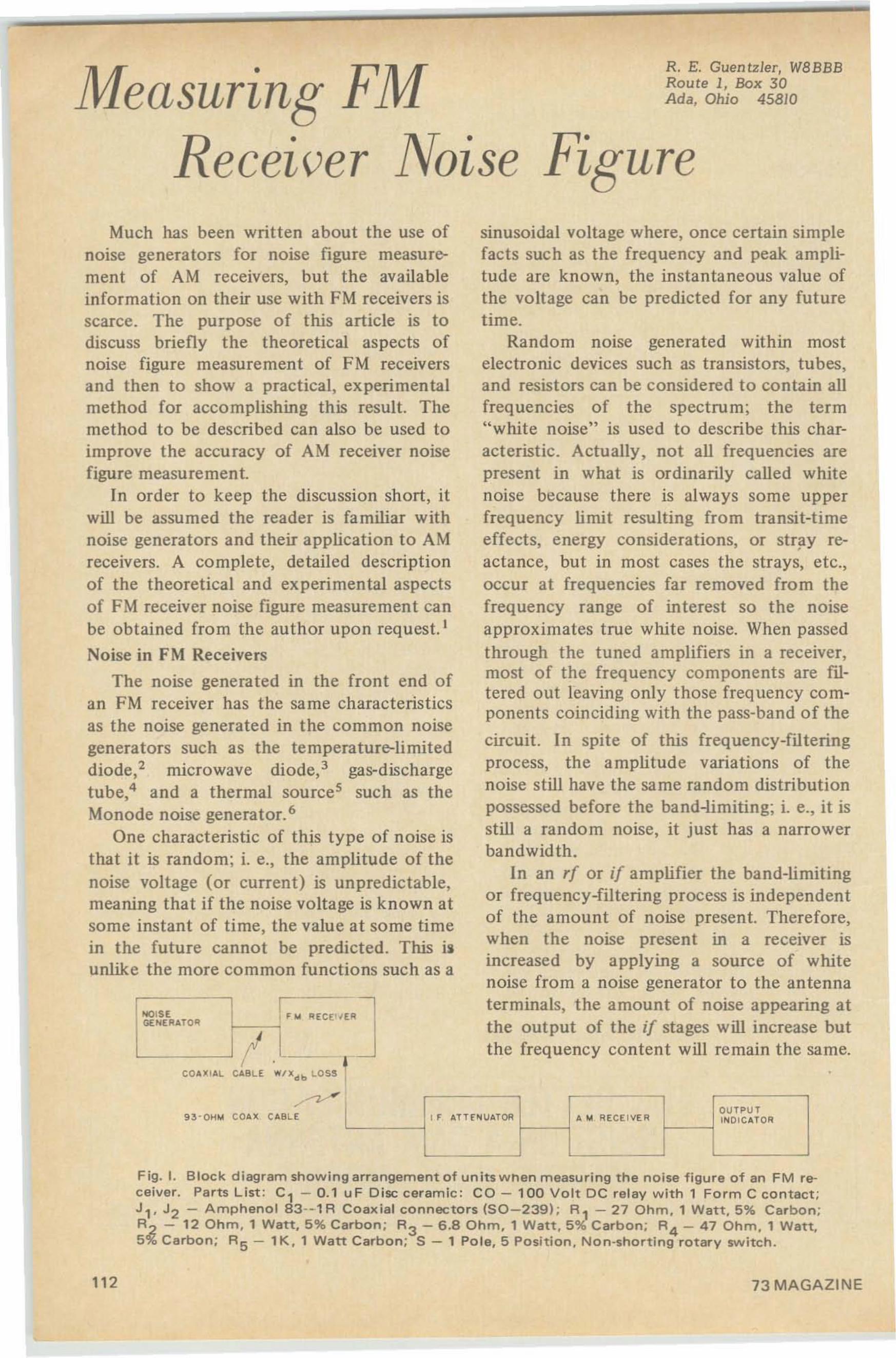
71 If . F'M R. E. Guentzler, W8BBB
1V1easuring ~~~:·O~ioBo~;~O
~ecei~er JVoise 1?iguresinusoidal voltage where, once certain simplefacts such as the frequency and peak amplitude are known, the instantaneous value ofthe voltage can be predicted for any futuretime.
Random noise generated with in mostelectronic devices such as transistors, tubes,and resistors can be considered to contain allfrequencies of the spectrum; the term"white noise" is used to describe this characteristic. Actually, not all frequencies arepresent in what is ordinarily called whitenoise because there is always some upperfrequency limit resulting from transit-timeeffects, energy considerations, or stray reactance, but in most cases the strays, etc.,occur at frequencies far removed from thefrequency range of interest so the noiseapproximates true white noise. When passedthrough the tuned amplifiers in a receiver,most of the frequency components are filtered out leaving only those frequency components coinciding with the pass-band of the
circuit. In spite of this frequency-filteringprocess, the amplitude variations of thenoise still have the same random distributionpossessed before the band-limiting; i. e., it isstill a random noise, it just has a narrowerbandwidth.
In an rf or if amplifier the band-limitingor frequency-filtering process is independentof the amount of noise present. Therefore,when the noise present in a receiver isincreased by applying a source of whitenoise from a noise generator to the antennaterminals, the amount of noise appearing atthe output of the if stages will increase butthe freq uency content will remain the same.
OUTPU T
" ATTfN UA,TOR A ... RECE IVE R INDIC ATOR
IF '" ~ECE"E~i-----;---,
1-COA )(I AL CABLE W/lld b LOS! I
~,
-'
-.QISEGE NE~ATO~
'--------------' I .L_
9 3 - 0H'" COAll CABLE
Much has been written about the use ofnoise generators for noise figure measurement of AM receivers, but the availableinformation on their use with FM receivers isscarce. The purpose of this article is todiscuss briefly the theoretical aspects ofnoise figure measurement of FM receiversand then to show a practical, experimentalmethod for accomplishing this result. Themethod to be described can also be used toimprove the accuracy of A~l receiver noisefigure measurement.
In order to keep the discussion short, itwill be assumed the reader is familiar withnoise generators and their application to AMreceivers. A complete, detailed descriptionof the theoretical and experimen tal aspectsof FM receiver noise figure measurement canbe obtained from the author upon req uest. I
Noise in FM Receivers
The noise generated in the front end ofan FM receiver has the same characteristicsas the noise generated in the common noisegenerators such as the temperature-limiteddiode.? microwave diode.? gas-dischargetube" and a thermal sources such as theMonode noise generator."
One characteristic of this type of noise isthat it is random; i. e., the amplitude of t henoise voltage (or current) is unpredictable,meaning that if the noise voltage is known atsome instant of time, the value at some timein the future cannot be predicted. This i.unlike the more common functio ns such as a
Fig. I. Block diagram showing arra ngement of u nits when measuring the noise figure of an FM rec e ive r. Pa rts Li st : C 1 - 0 .1 u F Disc ceramic : CO - 100 Volt DC re lay with 1 Form C contact ;J 1• J 2 - Amphenol 83- · 1 R Coaxial connecto rs (50-239) ; R 1 - 27 Ohm, 1 Watt, 5 % Carbon;R 2 - 12 Ohm , 1 Watt, 5 % Carbon ; R3 - 6 .8 Ohm, 1 Watt, 5 % Carbon; R 4 - 47 O h m, 1 Watt,S% Carbon; RS - 1 K , 1 Watt Carbon ; S - 1 Pole , 5 Position, Non-shorting rotary sw itc h.
112 73 MAGAZINE
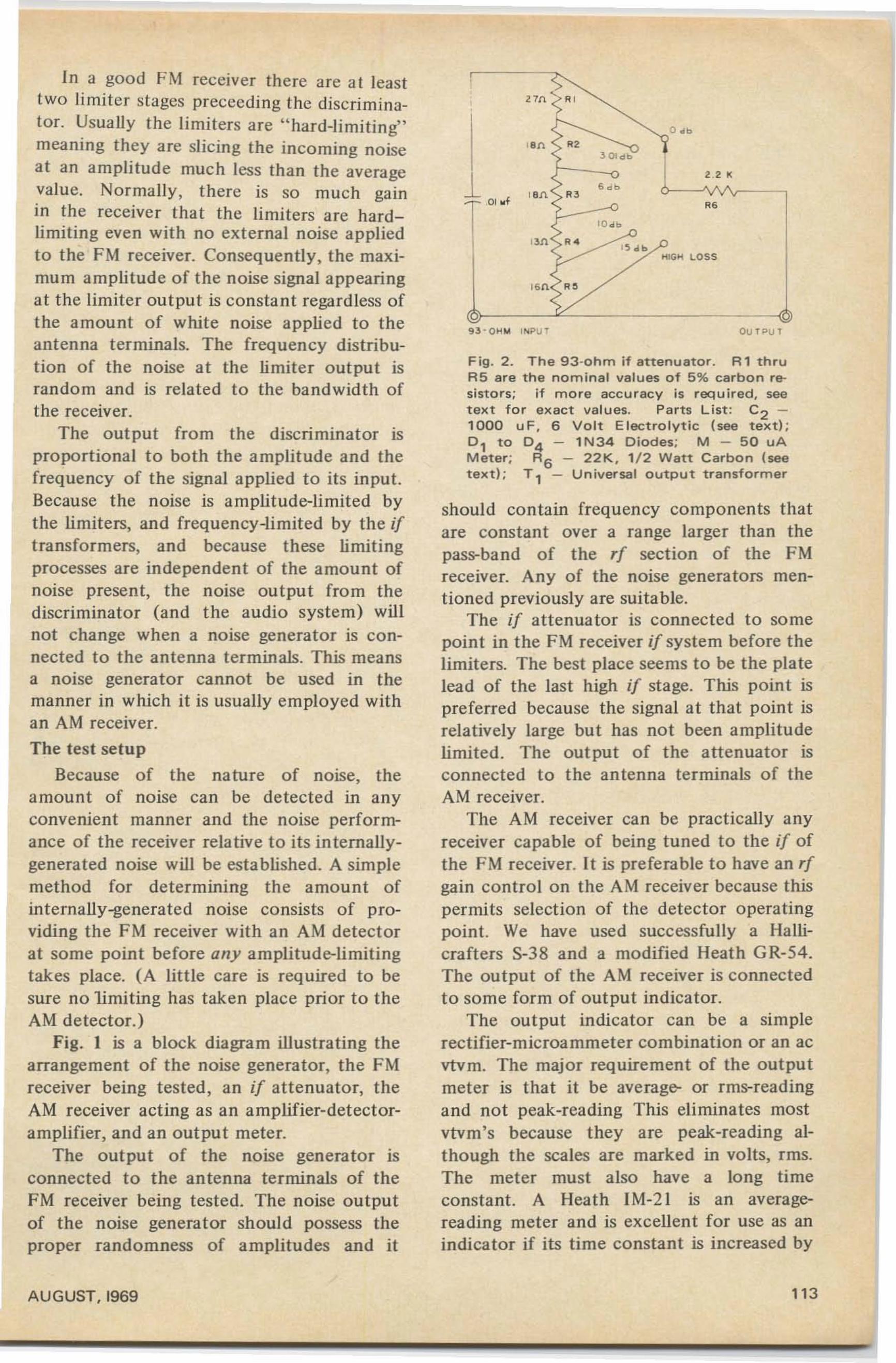
In a good FM receiver there are at leasttwo limiter stages prececding the discriminator. Usually the limiters are "hard-limiting"meaning they are slicing the incoming noiseat an amplitude much less than the averagevalue. Normally, there is so much gainin the receiver that the limiters are hardlimiting even with no external noise appliedto the F~l receiver. Consequently, the maximum amplitude of the noise signal appearingat the limiter output is constant regardless ofthe amount of white noise applied to theantenna terminals. The frequency distribution of the noise at the limiter output israndom and is related to the bandwidth ofthe receiver.
The output from the discriminator isproportional to both the amplitude and thefrequency of the signal applied to its input.Because the noise is amplitude-limited bythe limiters, and frequency-limited by the iftransformers, and because these limitingprocesses are independent of the amount ofnoise present, the noise output from thediscriminator (and the audio system) willnot change when a noise generator is connected to the antenna terminals. This meansa noise generator cannot be used in themanner in which it is usually employed withan AM receiver.
The test setup
Because of the nature of noise, theamount of noise can be detected in anyconvenient manner and the noise performance of the receiver relative to its internallygeneraled noise will be established. A simplemethod for determining the amount ofinternally-generated noise consists of providing the FM receiver with an AM detectorat some point before any amplitude-limitingtakes place. (A little care is required to besure no limiting has taken place prior to theAM detector.)
Fig. I is a block diagram illustrating thearrangement of the noise generator, the FMreceiver being tested, an if attenuator, theAM receiver acting as an amplifier-detectoramplifier, and an output meter.
The output of the noise generator isconnected to the antenna terminals of theFM receiver being tested. The noise outputof the noise generator should possess theproper randomness of amplitudes and it
AUGUST, 1969
OU TPUT
Fig . 2 . The 93-ohm if ertenueror , A'thruAS are the nominal values of 5 % carbon resistors; if more accuracy is required. seetext for exact values. Parts List : C 2 1000 us , 6 Volt Electrolytic (see text) ;0, to 04 - lN34 Diodes; M - 50 uAMeter; R6 - 22K, ' /2 Watt Carbon (seetext) ; T, - Universal output transformer
should contain frequency components thatare constant over a range larger than thepas..band of the rf section of the FMreceiver. Any of the noise generators mentioned previously are suitable.
The if attenuator is connected to somepoint in the FM receiver if system before thelimiters. The best place seems to be the platelead of the last high if stage. This poin t ispreferred because the signal at that point isrelatively large but has not been amplitudelimited. The output of the altenuator isconnected to the antenna terminals of theAM receiver.
The AM receiver can be practically anyreceiver capable of being tuned to the if ofthe FM receiver. It is preferable to have an rfgain control on the AM receiver because thispermits selection of the detector operatingpoint. We have used successfully a Hallicrafters S-38 and a modified Heath GR-54.The output of the AM receiver is connectedto some form of output indicator.
The output indicator can be a simplerectifier-microammeter combination or an acvtvm. The major requirement of the outputmeter is that it be average- or rrns-readingand not peak-reading This eliminates mostvtvm's because they are peak-reading although the scales are marked in volts, rms.The meter must also have a long timeconstant. A Heath IM-2l is an averagereading meter and is excellent for use as anindicator if its time constant is increased by
113
placing a 500 uf capacitor across the movement.
The attenuator
When measurements are made on anysystem , the most important items are thesignal source and the output indicator. Themost common source of error in noise figuremeasurements is the noise detector. Thiserror results from the generally-unknowndetector characteristics in the receiver beingtested (usually the detector is assumed to belinear but is actually square-law. giving, as aresult, noise figure values that are muchbetter than they actually are). In the methodof measurement being described here, theburden of measurement accuracy is placedupon the if attenuator.
The schematic diagram of the if attenuator is shown in Fig. 2. It is a simplevoltage-divider type having a 93-ohm inputimpedance. It gives six steps of accuratelyknown attenuation; 0.0, 3.0, 6.0, 10.0, 15.0,and some value greater than 40 db at 10 mhz(the last step isn't accurate and doesn't haveto be). The actual attenuation is not knownand is not relevant. Resistors R I thru R5 aremounted on a good-quality rotary switchusing the shortest lead-length possible. R6 isused to provide a relatively high load impedance to the attenuator independent ofthe input impedance of the AM receiver; itsvalue is relatively unimportant but should beat least 2.2k. The capacitor is used for deblocking. The entire unit should be mountedin a Minibox or similar shielded housing. A
•piece of RG-62B/U or similar 93-ohm cablewith a connector on one end and clips onthe other end is used to connect the attenuator to the receiver being tested.
The secret of the attenuator accuracy liesin the form employed. When attenuators ofthe T- or Pi-type are used. their accuracy iscritically dependent upon the source andload impedances presented to them. Theimpedance of an if amplifier or the antennaterminals on a tunable receiver are nebulous.Because of this, when T- or Pi-type attenuators are to be used it is recommended thatat least 60 db of attenuation be placed oneach side of the attenuator in order topresent a reasonably-well known impedanceto the attenuator in question." In addition,if the attenuator is to be variable. three
elements must be changed for every step ofattenuation. For noise figure measurementonly relative attenuation is important.Therefore, a voltage-divider type is ideal.
If 5% carbon-composition resistors havingthe values shown in Fig. 2 are used. theattenuator accuracy will be much betterthan that of the average AM receiver diodedetector. However. if more accuracy isdesired it can be obtained by one of twomethods. Which method is used is dependentupon the type of noise generator to beemployed when making noise figuremeasurements. The methods are:
I) Determine the actual attenuationvalues after the attenuator is built and markthe switch positions with these values, or
2) Trim the resistors to the exact valuesrequired for steps of 3.0 I, 6.0, 10.0, and15.0 db; the exact resistor values are:RI =27.2, R2 = 19.2, R3 = 17.2, R4 = 12.8,and R5 = 16.6 ohms.
The first method is difficult to do directly because precise vtvrn's at if frequencies are rare. However, an indirectmethod can be employed by measuring theresistors with a Wheatstone Bridge and calculating the expected loss from the devalues. So long as good construction practices are employed and good non-reactiveresistors such as Allen-Bradley type EB,Yz-watt, 5% carbon, are used, the calculatedlosses should be accurate.
The second method requires some meansof determining the dc resistance and istherefore similar to the first. Precision resistors can be used, so long as they arenon-reactive, or the Allen-Bradley resistorscan be used with their values "adjusted" byselecting individual resistors from a batch orby filing.
If a variable-output type noise generatorsuch as the 5722 diode is used when takingnoise figure readings, the "3 db" step shouldbe exactly 3.01 db. This would indicate thatthe second method should be used . If afixed-output noise generator such as theMonode is to be used, the first method isacceptable. The attenuators we built werecalibrated and adjusted using a combinationof the above techniques. A quantity ofAllen-Bradley resistors were obtained andthe values selected to give a 3.01 db step andto make the rest of the steps as close to the
114 73 MAGAZINE
desired values as was practical consistentwith not too much work. For example, oneattenuator came out with steps of 3.01,5.9,9.8, and 14.9 db.
Making the measurements
Connect the components as shown in Fig.1. The cable between the noise generatorand the antenna terminals of the FM receivermust have a known amount of attenuation.The input of the attenuator is connected tothe FM receiver if system by connecting thebraid of the RG-62B/U coaxial cable to thechassis of the receiver and clipping thecenter conductor over the insulation of theplate lead of the last high if stage.
Set the attenuator to give 0 db relativeloss. Disable the age in the FM receiver, if soequipped, and disable the ave and the ani inthe AM receiver. Tune the AM receiver tothe if frequency of the FM receiver. Set therf and af gain controls on the AM receiver togive nearly full-scale deflection on the output meter. Set the attenuator to the highloss position. The output meter should go tozero. If it does, the equipment is ready formeasurement. If it does not there is insufficient shielding or the AM receiver is toonoisy, and the condition will have to becorrected.
The remainder of the measurement discussion is divided into two parts accordingto whether a variable- or fixed-output noisegenerator is to be used.
A variable-output generator:
The detector in the AM receiver shouldbe as non-linear as possible in order to givethe largest change in output indication for agiven change in noise level. The detectoroperating point is adjusted by using a low rfgain setting and a high af gain selling on theAM receiver. If possible, set the detectoroperating point to give a 6 db change inoutput when a 3 db change is made in theattenuator setting. When adjusted, set theattenuator to the high-loss position and notethe output from the AM receiver. It shouldgo to zero. If it does, all is well and theattenuator can be set back to 0 db relativeloss and the measurement may proceed. If itdoes not, find out why not and correct thedifficulty.
AUGUST. 1969
Note the noise level indicated by theoutput meter. Set the if attenuator to 3.01db relative loss and increase the noise generator output until the output indicatorreads the same as it did with no noiseapplied and the allenuator set to 0 dbrelative loss. The FM receiver noise figure isfound by means of the formula :NFdb = ENdb - Xdb, where EN is the excessnoise of the noise generator and X is the lossof the coaxial cable connecting the noisegenerator to the FM receiver. If directlyconnected, X is zero.
A fixed-output generator
The AM receiver will have to be calibrated. This can be done by varying theattenuator and noting the change in theoutput indicator reading. The rf and af gaincontrols on the AM receiver are adjusted tomake the output indicator reading changethe same amount as the attenuator setting ischanged. Once the receiver is calibrated, themeasurement procedure is as follows: Connect a "quiet" termination to the FMreceiver antenna terminals thru the samecable used to connect the noise generator tothe receiver. Set the if attenuator to 0 db.Note the output from the AM receiver.Connect the noise generator to the FMreceiver in place of the "quiet" termination.Note the increase in output from the AMreceiver. The noise figure of the FM receiveris found from the formula: NFdb = ENdb Xdb - 10 log '0 (Y - I l, where En is Iheexcess noise of the noise generator, X is theloss of the coaxial cable connecting the noisegenerator to the FM receiver, and Y is theratio of the output power from the AMreceiver with the noise generator connectedto the FM receiver to the output power fromthe AM receiver with the "quiet" terminat ion on the FM receiver. Some of the burdenof the outpul change can be taken up by theattenuator. This is done by increasing theattenuator setting when the noise generatoris applied and calling the change in outputthe sum of the attenuator setting change andthe output meter reading change.
I t is advisable to listen to the noiseoutput from the AM receiver while takingthe measurements in order to detect signalsthat will cause erroneous results."
115
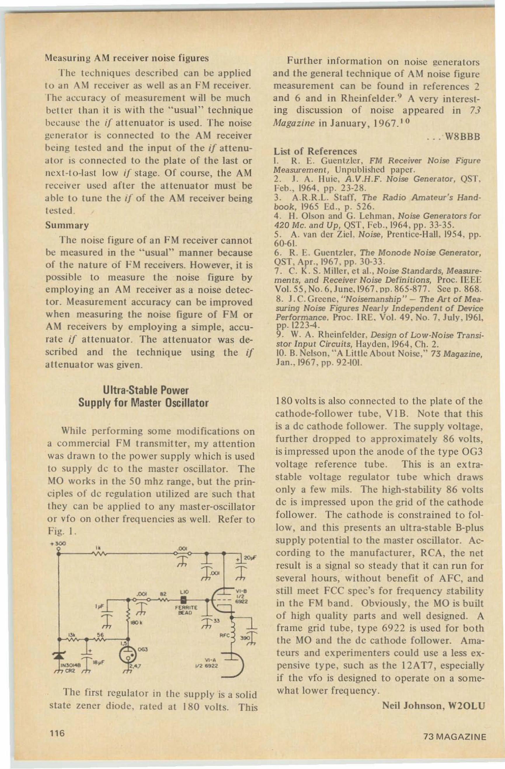
:\teasuring AM rec eiver noise figures
The techniques desc ribed ca n be a ppliedto an A~t receive r as well as an FM receiver.lhc acc uracy o f measurement w ill be muchbet te!" than it is w it h the " usual" techniquebecause the if att enuata !" is used . The noisegenera tor is connec ted to the AM receiverhcing tested a nd the in put of the if a ttenuutor is con nected to the plate of th e last ornext -to-last low if stage. Of cou rse, the AMrece ive r used a fter the altenuator must beable to tu nc the if of t he A M receiver beingtes ted .
Summary
The noise figure o f a n FM receiver cannotbe measured in the " usual" manner becauseof the nature o f FM rec eivers. Ho wever. it ispossible to measure the no ise figure byemployin g a n AM receiver as a noise detector. Measurement acc u racy ca n be improvedwhen measuring the no ise fi gure of FM o rAM receive rs by e mp loy in g a simple, accurate if attenuator. The attenuator was described and the technique using the ifa ttenua tor was given.
Further information o n noise gen eratorsand the genera l technique of AM no ise figuremeasuremen t can be fou nd in re ferences 2a nd 6 and in Rheinfelder.? A very interesting discussion o f no ise appeared in 73Magazine in January . 1967. 1 0
... W8BBB
List of ReferencesI. R. E. G uentzfcr , FM Receiver No ise FigureMeasurem ent, Unpubli shed paper.2..1. A. lillie, A.V.H.F. Noise Generator, QST.Feb ., 1964 . pp . 23-28.3. A.R.R.L. Staff. The Radio Amateur's Hsndbook, 1965 Ed., p. 526 .4 . H. Olson and G. Lehman , Noise Generators for420 Me. an d Up, QST, Feb., 1964 , pp . 33-35.5. A. van der Zie!. Noise, Prentice-H all. 1954, pp.60-61.6. R. E. Cucntzrer. The Monode Noise Generator,QST, Apr.•1967. pp . 30-33.7. C. K. S. Miller. et al., No ise Standards, Measurem en ts, and Receiver Noise Definitions, Proc. IEEEVo1.5 5. No. 6. June. 1967. p p . 865-877. See p. 868.8. J . C. Gree ne. "Noisemanship" - Th e Ar t of Measuring Noise Figures Nearly Independen t of DevicePerform ance. Proc. IRE. Vol. 49. No.7. July. 1961.pp.I223-4 .9. W. A. Rhcinfeldcr, Design of Low-Noise Transistor Input Circuits, Hayden , 1964 , Ch. 2.10. B. Nelson, " A Little About Noise," 73 Ma gazine,Jan .•1967. pp. 92-101.
Th e fi rst regula to r in the supp ly is a solids tate zener diod e. rated at 180 volts . This
180 volts is also connected to the plat e of thecathode-follower tube, V I B. No te th at t hisis a de cathode follower. T he sup ply voltage,furt her d ro pped to approx imately 86 volts,is impressed upon the anode of the t ype OG3voltage reference tube . This is an ext rastable voltage regulator tube w hich d rawso nly a few mils . The h igh-stability 86 voltsde is impressed upon the grid o f the cathodefoll ower. The ca t hode is const ra ined t o follo w, a nd this presents a n ul t ra-stable B-plussupply potent ial to the master oscillator. Accord ing to the manufacturer, RCA , the netresult is a signal so stead y that it can run forsevera l hours, without benefit o f A FC. andstill meet FCC spec's for freq uen cy stabilityin t he I'M band . Obviously , t he MO is bu ilto f high quality part s and well design ed. Aframe grid tube , type 69 22 is used for boththe MO and the de cat hode follower. Amateurs and experimenters could use a less expensive t y pe , such as t he 12 AT7 , especiallyif the vfo is designed to operate on a somewh at lo wer frequency.
Neil Johnson, W20LU
~..~V2 69 22
.00..
Ultra-Stable PowerSupply for Master Oscillator
While performing some mod ifications ona co mme rci al FM t ransmitter , my a tten tionwas dro wn to the power su pply which is usedto su pply de to the master oscillalor. TheMO works in the 50 mhz range , b ut t he principles of de regulation uti lized are such t h atthey can be ap plie d to any master-oscillatoro r vfo on o ther freq uencies as well. Refer toFig. I .
116 73 MAGAZINE
Raymond C. Sills K2ULR32 Ainsworth Av~nueEast Brunswick, N .J. 08816
Tf6uld lOu L ike To Be
A Broadcast En/3'ineer?
I'm sure many a ham has a little of thebroadcaster in his blood . After all , both theham and the broadcaster transmit information by means of electromagnetic radiation.Perhaps the only real difference between thetwo is in the intended recipient of theinformation : a feHow ham or the generalpublic.
It's often said that ham radio haslaunched many careers in electronics, andbroadcasting is no exception. In the earlydays of radio, there was little distinctionbetween amateur and " commercial" operation ; and the fellow who had the technicalknow-how to put a rig on the air for ham usecould certainly put a commercial stat ion onthe air. And it's true today, too, that manybroadcasting people are amateur operators,especially in the technical end of broadcasting.
I'm sure that many a Novice, having builthis first rig, wonders what goes into a 50 KWbroadcast rig in one of those big city stationsor perhaps even his local 25 0 watter. Thereare many similarit ies between any onestation and all the others. Obviously , eachstat ion needs an antenna system, transmitter, audio (or video) control and distribution equipment, and a place to originatethe broadcasts. But apart from that, eachstation invariably has its own specialtechnical need s, equipment, and facilitieswhich are like no other station's.
It is probably safe to say that most hamsin broadcasting are in the technical end of
AUGUST. 1969
things, although there are a few well-knownentertainment personalities who have a•ticket. Of those fellows who do work in thetechnical department, most stations givethem the title of "engineer," even thoughthey might not have a degree in electricalengineering. An engineer's duties usuallyconsist of operating the transmitter - thatis, observing the operation of the transmitter, since most of today's transmittersneed little attention in day-to-day operation;and/or operating the studio equipment ;and/or repair and maintenance of all thestat ion's electronic gear; and/or clericalduties related to the technical operation ofthe station - ordering spare parts, newtubes, scheduling manpower, etc. I use the"and/or" because the total number of jobduties will depend on the size of the stat ionat which an engineer is employed . Atstations in small markets (cities) or smallstat ions in large markets, the engineer willdo most or all of the above duties. The ChiefEngineer, in addition to these duties, has theoverall re sponsibility and legal obligatio n tothe stat io n ownership and the FCC to seethat the sta tio n is opera ti ng within the termsof its license and the FCC rules and regulations. To be sure, all licensed transmitteroperators (and all transmitter operators mustbe licensed) have the same responsibility ,but it is the Chief Engineer at whom theFCC and the stat ion management will glareif there are any technical irregularities.
Job duties are often highl y specialized at
111
the "large city" stations and network operations. Very often, a man will specialize inone small area in the broadcast technicalfield. For example, he might be a maintenance man, in charge of only onc type ofequipment, such as a particular model oftape recorder. But since large stations havemany of those tape machines, he is usuallyquite busy just keeping them all runningproperly with routine maintenance: lubrication, cleaning, checking tubes, alignment,and so forth. Some of the fellows who dothis specialized maintenance arc so proficient and familiar with their tape machinesthat they can diagnose and repair a fault in10 minutes which would take the averageengineer two hours to fix.
At one of these large stations, an engineer - or technician, as he is sometimesmore accurately called, - is almost invariably a member of one of the majorbroadcast engineer's unions: lBEW, NABET,or fA TSE. As such, he is collectivelybound to a contract with his employer,and this contract spells out, quite precisely,what his duties shall be.
As you might expect, some fellows (andgals, too) show a preference or an aptitudefor one or more of the various specialties inthe broadcast technical field. One chapmight be a great studio console operator;another, a great tape editor; a third might bea transmitter expert; and yet another mightenjoy working in the maintenance shop.And, of course, some people are quitecompetent in more than just one specialty.
If you're still all hot about becoming abroadcasting engineer, plan to make a visitto a station, TV or radio, whichever isavailable or preferable, and talk to some ofthe boys. Almost all of the fellows in thebroadcast business would be glad to showyou around and answer your questions. Mostprobably, you'll be told that you should getyour commercial radiotelephone operatorslicense.
There are three grades of licenses : FirstClass, Second Class and Third Class, fromtop to bottom, and a total of five exam"elements" that you must pass for a FCCticket. If you can pass elements 1 and 2, youare qualified to receive a third class .license.If, after passing elements I and 2, you passelement 3, you get the Second Class ticket.Finally, when you pass the fourth element,you get the First Class License. You could, ifyou like, take all four elements in the sameday, but most people prefer to "come up
118
through thc ranks" and get all of thelicenses, or at least the Second Class andthen the First Class. The First Class Licenseis very much like what the Gencral Classham license used to be: you get all operatingprivileges for all types of radiotelephone (noCW) and TV stations in the commercialfield: broadcast, police, taxi, government,microwave relay, ctc. This is the license thatall Chief Engineers must have.. and the onethat most regular engineers have. It is a very,very valuable asset to have if you intend toget a job in the broadcast technical field (orannouncing and Deejay work, for thatmatter.} Without it, you cannot legally tuneup any broadcast transmitter or operatecertain classes of broadcast stations: TV, AMstations with directional antenna or stationsrunning more than 10 KW. The Second Classallows you to service and tune up CB andtwo-way communications gear (police, taxi,etc. rigs) and the Third Class lets you onlyoperate two-way gear and marine radiotelephone equipment. There is a provision ofthe rules that allows second and third classmen to operate certain types of broadcaststations: those running less than 10 KW witha non-directional antenna. The operation islimited to turning the carrier on and off atthe beginning and end of the broadcast dayor for EBS tests, and adjusting the power bymeans of a simple control to compensate forchanges in line voltage, loading, etc., thatmight put the transmitter more than thelegal limits of 10% below or 5% above thelicensed power. If a third class man works ata station, he must pass an additional examelement: element No.9, which deals withsimple routine tasks at a station, such astaking meter readings, keeping logs, frequency and power tolerances, etc.
H you are pretty good at theory, you canprobably train yourself to pass the FCC test.Also, you might enlist the aid of a friendwho is also studying for a commerciallicense. Here, the use of a license manual willno doubt be very helpful. Otherwise, itmight be worthwhile to investigate one ofthe resident or correspondence schools thatspecialize in training people to pass FCCexams. As I recall, there are even someschools that guarantee you a ticket - t hey'llkeep training you at no additional cost untilyou pass, should you not make it on the firsttry.
Once you have a license, or are at leastwell on your way toward getting it, get toknow someone who works at a station.
73 MAGAZINE
•
Don't bug him by constantly calling orvisiting him. If you use good judgment anddon't overdo it , chances are he'll be morethan glad to help you along with the licensetest or getting a job. There's usually a fairlygood gra pevine between stat ions in anyonearea, and when a job opens up . the wordusually travels along to other nearbystations. Also. quite a few of the small localstations will train young fellow s by hiringthem on a part-time basis at a very nominalwage. In the large cities, inexperienced menwith a license can often find work assum mer vacation relief engineers. If theycatch o n quickly to how things are done atthat particular station, chances are thestation will ask them to return the next year.This is an excellent opportunity for a collegefellow to earn extra money during thesummer.
I can't emphasize too strongly this bitabout having a license. It is true that manybroadcast engineers in the large cities do nothave a license. But you are worth muchmore to an employer if you have a ticket :you can legally operate transmitting equipment and this allows him greater flexibilityin assigning you your duties. Also, a licenseis proof to an employer that you do knowsomething about electronics.
Another training possibility is to offeryour services gratis to an educational noncommercial F~l station. These statio ns oftenoperate on very limited budgets and can useall the help they can get for free. See if thereare any college FM stations in your area.(Hint : if you have any FM stations in yourarea that operate below 92 .0 mhz, they areno n-commercia l by FCC definition . Thereare. however. a few " listener sponsored"stat io ns that operate in the commercialband, 92 .0 to 108.0 mhz.)Money
Pay is often not as much as you mightexpect for a "show biz" industry - probablyon the order of five to six thousand dollarsannually at t he average station. For abeginner with something less than a firstclass ticket , remuneration will be $ 1.25 to$2.5 0 per hour at a small or medium-sizedstat ion. At large metropolitan stations wherethere is a union involved, you can expectsalaries in the $200 to $300 per weekbracket , with overtime pay. night-timedi ffe rential pay, penalty payments formi sscd mea l period s , and " shortturn-around " (Jess than 12 hours betweenshifts) compensation . The big companies.
AUGUST. 1969
like ABC, CBS and NBC, et c., have elaborateemployee benefit programs in the form ofinsurance, hospitalization, pensions, stockpurchase plans, liberal vacations, and so o n.
So it's no t surprising that many peoplewould like to get to work for the "big"companies, since that's where the moneyand the action is. There is a rea sonablecha nce that you can land a job at one of t hebig city outfits if you have some experience,good recommendations, and perhaps so mefor ma l t raining. The large companies havelarge manpower needs and lose a few menevery year through retirement and jobhopping. The need for manpower is beingreduced so mewhat these days by theincreasing use of automation and automateddevices to control programs, performswitching, operate transmitters, and so forth .And today's solid-state gear doesn't breakdown as often as it s vacuum tube predecessors. Also, programming - at least radioprogramming - is not as elaborate as it wasin years past : deejays, talk, news, sports , etc.arc now the rule, instead of the soap operasand variety shows which now fill our TVchannels.
Good luck o n the test, and welcome tothe club, OM.
... K2 ULR
Footnotes:IATSE: International Alliance of Theatrical StageEmployees. 1270 Avenue of the Americas, NewYork, N.Y. 10019.NABET: National Association of Broadcast Empployecs and Technicians, 135 West 50th Street,New York, N.Y. 10019.IBEW: International Brotherhood of ElectricalWork ers, Local 1212, 150 Fifth Avenue, New York.N.Y. 10014 .
What's with UFO 's ?
Check in the UFO N ET
on 14,300 kc
WEONESDAY NIGHTS at 9 prn EST '-'
Salesman Wanted :To sell Instant Gourmet kits. These uni
que black leather kits are filled wit h eightindividual containers of special seasonings.A good salesman should sell 1000 of these amonth , and earn a very good commission.Send yo ur credentials to Instan t Go urmetPeterborough, N.H. 03458 .
119
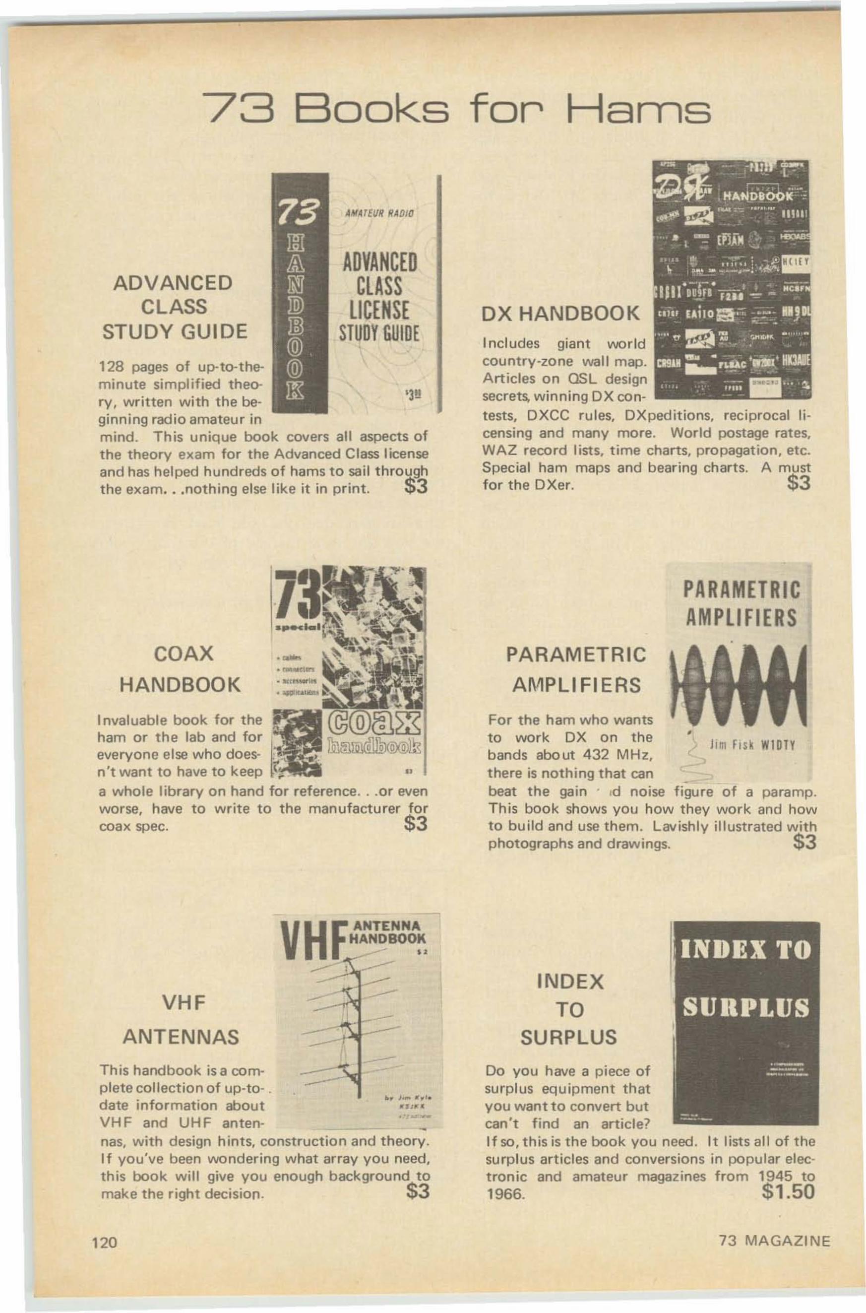
73 Books for Hams
Includes giant worldcountry-zone wall map.Articles on QSL designsecrets, winning OX contests, DXCC rules, DXpeditions, reciprocal licensing and many more. World postage rates,WAZ record lists. time charts. propagation. etc.Special ham maps and bearing charts. A mustfor the DXer, $3
DX HANDBOOK
'3g
ADVANCEDCLASS
LICENSESTUDY GUIDE
ADVANCEDCLASS
STUDY GUIDE
128 pages of up-to-theminute simplified theory. written with the beginning radio amateur inmind. This unique book covers all aspects ofthe theory exam for the Advanced Class licenseand has helped hundreds of hams to sail throughthe exam...nothing else like it in print. $3
PARAMETRICAMPLIFIERS
Jim f ISk W1DTY•
For the ham who wantsto work DX on thebands abo ut 432 MHz,there is nothing that can _beat the gain . .d noise figure of a paramp.This book shows you how they work and howto build and use them. Lavishly illustrated withphotographs and drawings. $3
PARAMETRIC
AMPLIFIERS
COAX
HANDBOOK
1nvaluable book for the p:1ham or the lab and for ~everyone else who does- ~,
n't want to have to keep '.. II
a whole library on hand for reference.. .or evenworse, have to write to the manufacturer forcoax spec. $3
INDEXTO
SURPLUS
Do you have a piece ofsurplus equipment thatyou want to convert butcan't find an article?If so, this is the book you need. It lists all of thesurplus articles and conversions in popular electronic and amateur magazines from 1945 to1966. $1.50
VHfANTENNAHA~BOO~
---.: --»>: ------VHF
ANTENNAS
This handbook is a complete collection of up-to- .
h J.~ ~. '.
date information about _ ft••.. ...VH F and UH F anten- _nas, with design hints, construction and theory.I f you've been vvondering what array you need,this book will give you enough background tomake the right decision. $3
120 73 MAGAZINE
73 USEFULTRANSISTOR
CIRCUITS
73 USEFUL ;
TRANSISTOR CI RCUI#S~~
If you've been lookingfor a t ransisto r ci rcuit todo a specia l job, chancesare there is a circuit int h is book t hat w ill give you a head sta rt. Itcovers c ircu its fo r audio, receivers. transmittersand test eq u ipment. $1
,A n invaluable referencebook . Covers recti f iers, mixers. detectors.mod ulato rs, FM detec-tors. noise limiters. AGe. BFO'/ O-multi pli er.AFC. Va ricap tuning audio clippers, ba lancedmods, field-st rength meters, RF probes. zeners.contro l ci rcu its, etc . III d ifferent circu its. $1
DIODE
CIRCUITS
HANDBOOK
r
SIMPLI FlED
MATH
CW by W6SFM explains code and how tolearn it. 501!
Does math scare yo u?- It shou ldn't . Thiseasy-t o-understand bookexpla ins t he simplif iedex pone ntial syst em of arit hmet ic. s imple formulas, logarithms, and their application to theham shack . 501!
II
.----
ATvE."'.W1IrE<
ANTHOlOGY f962· 6-4
HAMTELEVISION
The A mateur T elevisionAnthology is a collection o f the technicaland const ruction articlesf rom theATV Experimenter, edited by W0 K YQ.If you 're interested in AT V, this is the book foryou. It covers t he gamut f rom the simple to Ihecomplex in amateur t elevision equipment . :ti3
MILITARY SURPLUS TV EQUIP-MENT by W4WKM is a necessit y to the sur-plus-scrounging ATV add ict. $1
CUMULATIVE INDEX lists all the art icles in 73 up through December 1966. 25i
••••••••••••
•••••••Call ...............• :
•••••••••••••••••••••
Please send me the boob checked at left:
City State ZipBoob shipped prepaid in US and Canada.
Address ... ....... .............................................•.....................•.•
Na me ••••••••••••••••••••••••••••••••••••••••••••••••••••••••
73 MagazinePeterborough, N. H. 03458
_ Coax Handboo k $3.00_ Transisto r Circuits $ 1.00_ I ndex to Surplus $1.50_ Paramet r ic Ampl ifiers $3.00_ H am ATTy $3.00_V H F A ntennas $3.00
_Si mpli f ied Math $ .50_ AT V Anthology $ 3 .00_ CWo . • . . • . . . . . . . .. . . : $ .50_ Milit ary TV $ 1.00_Cumulat ive Index $ .25_ D X Handbook $3.00_ Advanced Class $ 3.00
••••••••••••••••••••••••••••••••••••••••••••••••••••••••••••••••••••••••••••••••••••••••••••••••••••••••••••A UGUST, 1969 121
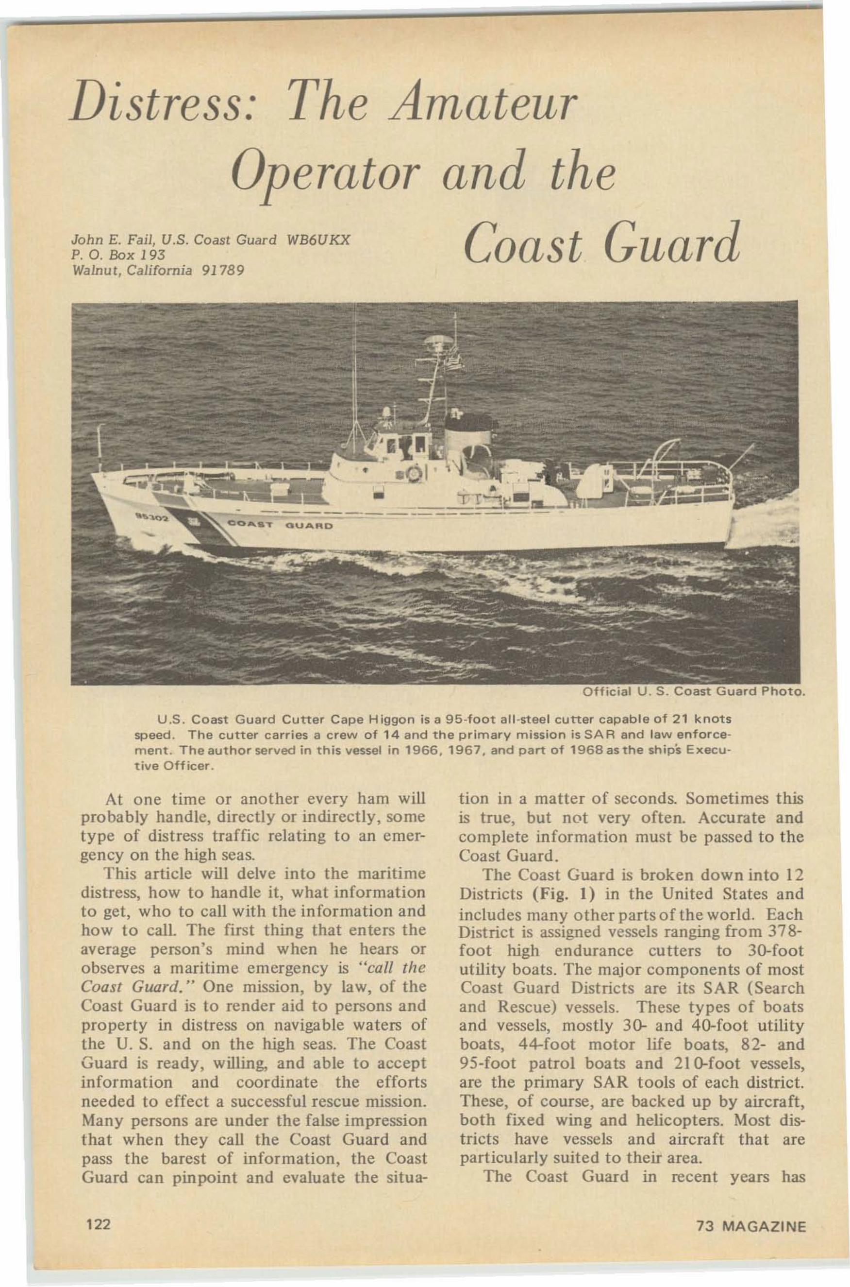
Distress: The Amateur
WB6UKX
Operator and the
Coast GuardJohn E. Fail, U.S. Coast GuardP. O. Box 193Walnut , Californ ia 9178 9
Off icial U . $. Coast Guard Photo.
U ,S . Coast Guard Cutter Cape H iggon is a 95-foot all-steel cutter capable of 21 knotsspeed. The cutter c arr ies a crew of 14 and the primary mission is SAR and law enforcem ent. The author served in t h is vesse l in 19 66 , 19 67. and p art o f 19 6 8 as the ships Execut ive O ffi ce r.
At one time or another every ham willprobably handle, directly or indirectly, so metype of distress traffic relating to an emergency on the high seas.
This article will delve into the maritimedistress, how to handle it, what informationto get, who to call with the information andhow to call. The first thing that enters theaverage person' s mind when he hears orobserves a maritime emergency is "call theCoast Guard." One mission, by law, of theCoast Guard is to render aid to persons andproperty in distress on navigable waters ofthe U. S. and on the high seas. The CoastGuard is ready, willing, and able to acceptinformation and coordinate the effortsneeded to effect a successful rescue mission.Many persons are under the false impressionthat when they call the Coast Guard andpass the barest of information, the CoastGuard can pinpoint and evaluate the situa-
tion in a matter of seconds. Sometimes thisis true, but not very often. Accurate andcomplete information must be passed to theCoast Guard .
The Coast Guard is broken down into 12Districts (Fig. I) in the United States andincludes many other parts o f the world . EachDistrict is assigned vessels ranging from 378foot high endurance cutters to 3D-footutility boats. The major components of mostCoast Guard Districts are its SAR (Searchand Rescue) vessels. These types of boatsand vessels, mostly 30- and 40-foot utilityboats, 44-foot motor life boats, 82- and95-foot patrol boats and 210-foot vessels,are the primary SAR tools of each district.These, of course, are backed up by aircraft,both fixed wing and helicopters. Most dist ricts have vessels and aircraft tha t areparticularly suited to their area.
The Coast Guard in recent years has
122 73 MAGAZINE
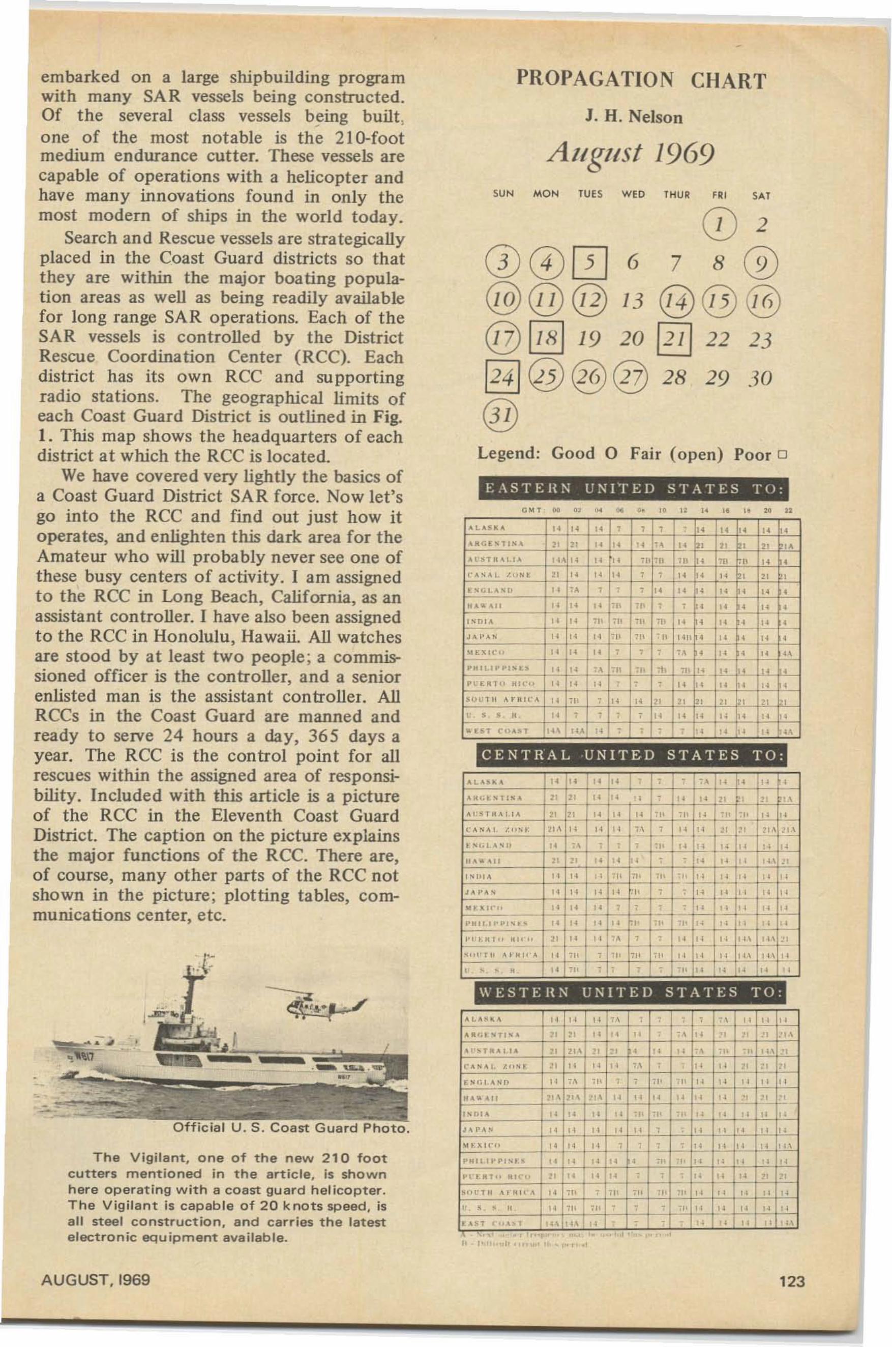
SUN MON TUE S WEO TH UR FR! SAT
30
23
29
1 , . I ' I • • "
6
13
"
0 "" .. 0
PROPAGATION CIIART
J. H. Nelson
AI/gl/st 1969
EASTEHN UNI"rED STATES TO :
(]) 27 8 ®
@@@@~ 19 20 12/ 122
~@@@28
®
0 0 0@@@
Legend: Good 0 Fair (open) Poor 0
"1' 10
, ". • 00 " , •~LU ~~ " " "
, , , •
" " " " "~KG ESTl~A " " " " " " " ,
",
" "HSTK~l.IA '" " " " "',II ,,, , tn -" "
," A , " I, ~UN , " " " " , ,
" " ",
",
"' "LA' '' " " , , ," " • " • " •
HAlO .• " " " ",,, .1' , , • "
," •
"DI. " "t;; ,II .11 :11 " I"- "
,"
,t-,~ ·H "A ' " " ," ,Il " HH ,
",
" ,- -, _.">o XIC" -I.'.' " r"
, ,"
,"
," "
rHIt.I~PlS l.~ " " " ,II ". 7\' ru " ", , ,
Pl' O:KTu IiH'" " " ", , • "
," " " •
'!)UTI' .A.HIe",' " '" r " " " " " " " ",
", • , " t , • • " " " " " " "
.. [ 5 1 (""~., '" ,u ", , , r" ,. I,.
" "CENTRAL -UNIT E D STATES TO:
' L "~ ~ " " 11 il. , • , • " !~ ",
'KG> ~llS~ " " " " , • " " " " " "~ 1 " sT K ~ I , I~ " " " " f-"- ,.' ,Il " . <I' -" " "," ~ '~I I.""'. '" " " 1" " 1'- I " ~~~ " ~, -- 2:\ I ~''';j~sl> " " , · , -" " " " " " ",,~ ... OIl " " " "
, - - " I " " II" "I , 1>1 A " " " W 7., '" 1: 1,1-:'- .~~ " " "J "' ~ " " " " " " t , I -I " " " "- -.. t: ~,,'" " " "
, • 1-'- - " " j'~ " "- -PKIl."·P",' , " I" " " " ,Il -,. " " " " "-'" '.Hl" K I' " " " r'.' " f'-
,1:-1:'-
. 1.1 '" '" f~---- _.,,, "I" "'H"" " <I' • ". ,I< ,I' H 1 -1 !C +,-1~ j--!-Hf"-, , , , "
,,, , , - 'I' " " " " "WESTE UN UNITED STATES TO :
I,-,' L ~ "K' " " " • ,'- , 7·\ " " "" " " " " " " -, "
I,; .', \• • " , "I'~
OJ sTlI~'." " '" " ",
" " " <I' I ", ,,' -,(" 0' 01. I ,," • " " " " " , ,
" " " " "t: " 't . • "11 " " 110 , , '" -,. " " " " "II . .. ~ II '" '" '" " " " " " " 1"- " -,,,"I ~ " " " " -" -" -, " " " " "J A PA'
" " " " " • ," t"'- " " "
"" " 1<'0 " " " _2 , - ," " " " ,"
I '"pHI1II'I"IS'.' " " " ", ". " " " " "
PI"".'" 111("" " " " ", , ,
" " " " ".."" " AI "I'"' " ,[I , ,I' 71< 'I' 7!l " " " " "" , ,
" ",,,
'", , • ,I' " " " " "
• AS' ""'~1 '" '" " - " " " " '"- - "
I
Official U. S . Coast Guard Photo.
T h e Vigilant, one of the new 210 footcutters mentioned in the article, is shownh ere operating with a coast guard helicopter.The Vig ilant is capable of 2 0 knots speed, isall steel construction. and carries the latestelectronic equ ipment available.
embarked on a large shipbuilding programwith many SA R vessels being constructed.Of the several class vessels being built ,one of the most notable is the 21 G-footmedium endurance cutter. These vessels arecapable of operations with a helicopter andhave many innovations found in only themost modern of ships in the world today.
Search and Rescue vessels are strategicallyplaced in the Coast Guard districts so thatthey are within the major boa ting population areas as well as being readily availablefor long range SAR operations. Each of t heSAR vessels is controlled by the DistrictRescue Coordination Center (RCC). Eachdistrict has its o wn RCC and supportingradio stations. The geographical limits ofeach Coast Guard District is outlined in Fig.I. This map shows the headquarters of eachdistrict at which the RCC is located.
We have covered very lightly the basics ofa Coast Guard District SAR force. Now let'sgo into the RCC and find out just how itoperates, and enlighten this dark area for theAmateur who will probably never see one ofthese busy centers of activity. I am assignedto the RCC in Long Beach, California, as anassistant controller. I have also been assignedt o the RCC in Honolulu, Hawaii. All watchesare stood by at least two people; a commissioned officer is the con troller, and a seniorenlisted man is the assistant controller. AllRCCs in the Coast Guard are manned andready to serve 24 hours a day, 365 days ayear. The RCC is the control point for allrescues within the assigned area of responsibility. Included with this article is a pictureof the RCC in the Eleventh Coast GuardDistrict. The caption on the picture explainsthe major functions of the RCC. There are,of course, many other parts of the RCC notshown in the picture; plotting tables, communications center, etc.
AUGUST,I969 123
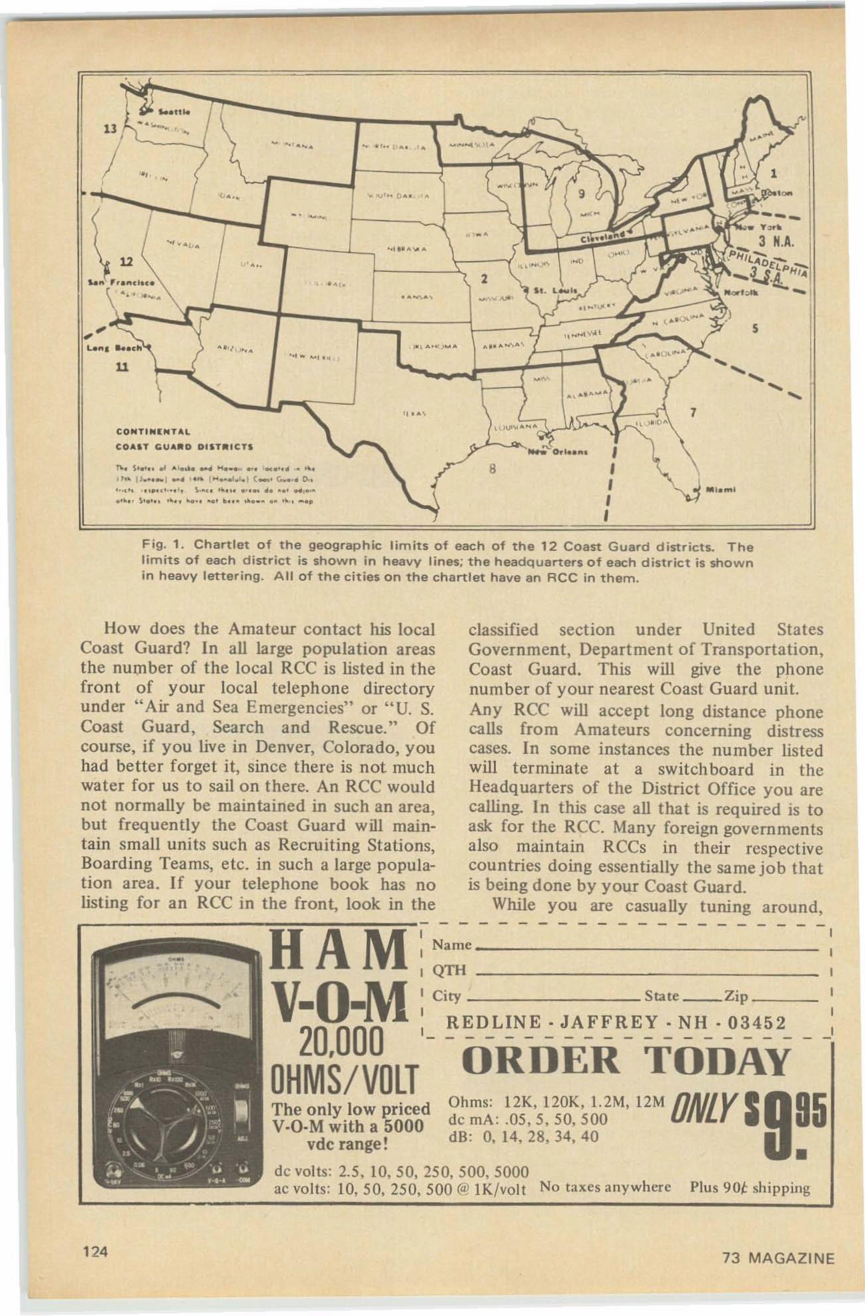
1
5
.... ................
........,
7
2
""'--"'_""0.1.. ... ,8 ,,,,
._.
' I . .. ,
......... .
..,.. ...,'.~ · 'l ... ..
-., ...,...
,.,. ..
CONT",,,un"'L
CO""T COU ....O DISTRICTS
n.. ~ ' _ '"" .. 11 1 , ••• , ) C_. c.... .• 0..'".', , '. \ ' . ' -,." ' " \ , 10 ,. ' , ~••
12
u
11 ,
I
Fig. 1 . Chartlet of the geographic limits o f each of th e 12 Coast G uard d istr icts. Thelimits of each d ist rict is shown in h eavy lines; the head q uarters of each d istrict is shownin heavy letter ing . All of the cities on the chartlet have a n RCe in th e m .
•Plus 90t shipping
- - - - - - - -ORDER TODAY
95
classified section under Unite d Sta tesGovernment, Department of Transporta tion,Coast Guard. This will give the phonenumber of your nearest Coast Guard unit.Any RCC wiU accept long distance phonecalls from Amateurs concerning distresscases. In some instances the number listedwill terminate at a switchboard in theHeadquarters of the District Office you arecalling. In this case aU t hat is required is toask for the RCC. Many foreign governmentsalso maintain RCCs in their respectivecountries doing essentially the same job thatis being done by your Coast Guard.
While you are casually tuning around,- - - - - - - - - - - - - - - - - - -
I
I
I
I
I
I- -
Ohms: 12K, 120K , 1.2M, 12M ONLY Ide rnA : .05,5 ,50, 500dB : 0, 14, 28, 34, 40
Name _
I QTH
I City State Zip _
I RED LINE . JAFFREY. NH . 0 3 4 5 2I------ --- --
The only low pricedV·O·M with a 5000
vdc range!
de volts: 2.5, 10, 50,250,500,5000ac volt s: 10,50. 250. 500 «i! l Kjvol t No taxes anywhere
H A MV-O-M
20,000OHMS/ VOLT
How does the Ama teur contact his localCoast Guard? In aU large population areasthe number of the local RCC is listed in thefron t of your local telephone directoryunder "Air and Sea Emergencies" or "U. S.Coast Guard , Search and Rescue." Ofcourse, if you live in Denver, Colorado, youhad better forget it, since there is not muchwater for us to sail on there. An RCC wouldnot normally be maintained in such an area,but frequently the Coast Guard will maintain small units such as Recruiting Stations,Boarding Teams, etc. in such a large population area. If your telephone book has nolisting for an RCC in the front, look in the
124 73 MAGAZINE
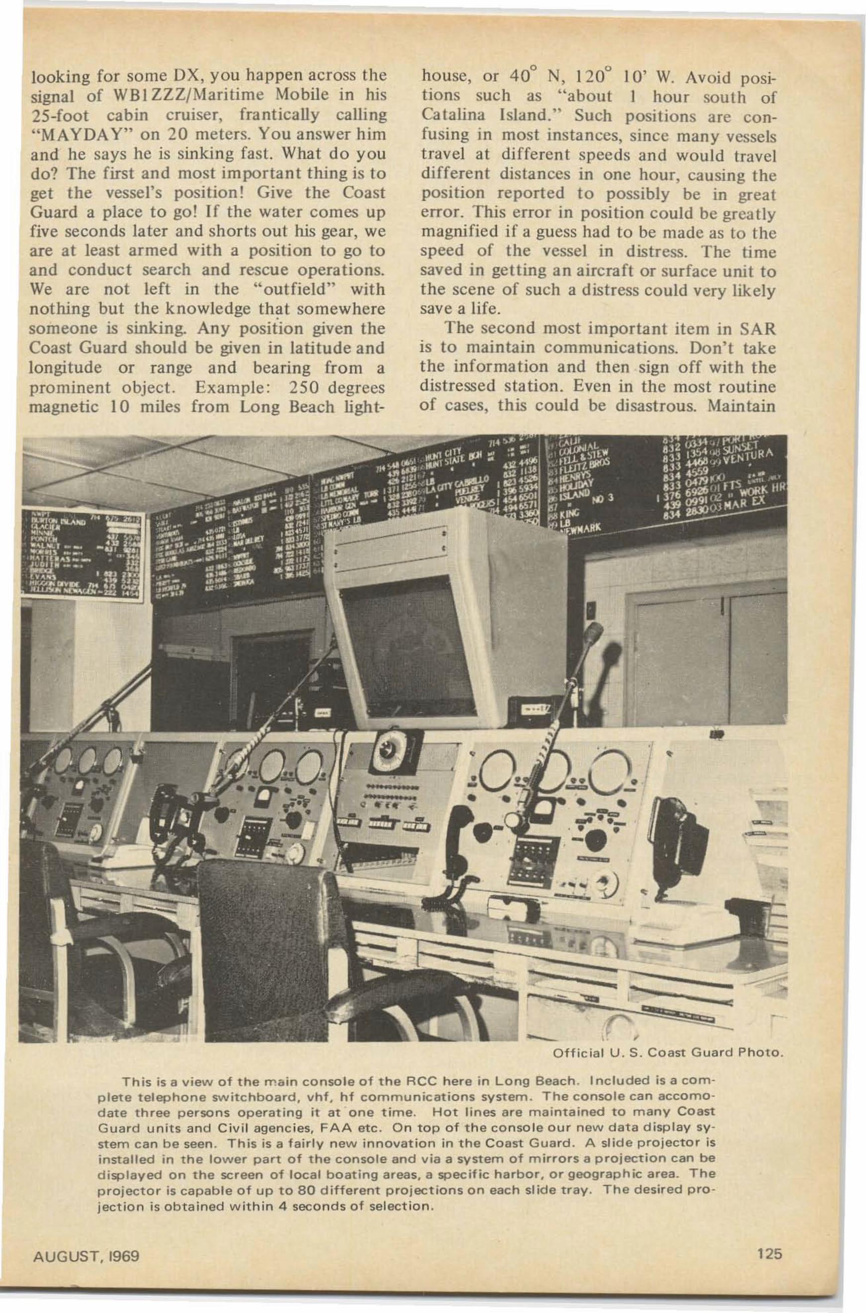
looking for some OX, you happen across thesignal of WBI ZZZ/Maritime Mobile in his25-foot cabin cruise r, frantically calling"MAYDA Y" on 20 meters. You answer himand he says he is sinking fast. What do youdo? The firs t and most important thing is toget the vessel's position! Give the CoastGuard a place to go! If the water comes upfive seconds later and shorts out his gear, weare at least armed with a position to go toand conduc t search and rescue operat ions.We are not left in the "outfield" withnothing but the knowledge that so mewheresomeone is sinking. Any position given theCoast Guard should be given in latitude andlongitude or range and bearing from aprominent object. Example : 250 degreesmagnetic 10 miles from Long Beach ligh t-
o 0
house, or 40 N, 120 10' W. Avoid posi-tions such as " about I hour sout h ofCa talina Island:' Such posit ions are confusing in most instances, since many vesselstravel at different speeds and would traveldifferent distances in one hour, causing theposition reported t o possibly be in greaterror. This error in position could be grea tlymagnified if a guess had to be made as to thespeed of the vessel in distress. The timesaved in getting a n aircra ft or surface unit tothe scene of such a distress could very likelysave a life.
The second most impo rtant it em in SA Ris to maintain communica tions. Don't takethe information and then sign off with thedistressed station. Even in the most routineof cases, this could be disastrous. Maintain
•- - "",d(; ,
r:O f f icia l U . S. Coast Guard Photo.
-"
?'), •I, ..~.- -• •
:7;::Z:J-:'-- '- ~
-=•• ,- -."-~ v •- ,• -,
T h is is a view o f the main c o n so le of the RC C here in L ong Beach . Included is a comp lete t el eph o n e sw itch board , Vh f, hf c o m m u n icat io ns svsrern. T h e console ca n accomodate three p er so n s o perat ing i t at one time. Hot lines are m aintained t o m any Co astG u ard units and Civi l agencies, FAA etc . O n top of the co nso le our n ew data display syst em ca n b e seen . This is a fairly new innovation in the Coast G u ard. A slide projector isin stall ed in the lo w er par t o f the c o nsole an d via a syst em of m irrors a p roject ion c an bed isplayed o n the screen o f loc al boating areas, a specif ic h arb or , o r geograph ic a rea. T heprojector is cap ab le o f up to 8 0 d i fferen t projections on each slid e tray . The desired pro jection is obtained within 4 seconds of selection .
A UGUST, 1969 125
communications with the distress unit untila Coast Guard unit arrives on the scene orthe distressed vessel has communicationswith a Coast Guard unit and you are releasedby tbe Coast Guard and/or the distressedunit. PCC regulations clearly states thatd istress traffic takes priority over all otherco mmunications.
Third co mes the miscellan eous information. but of co urse this is still veryimportant and should be obtained in everycase possible . These are items such asthe length of the vessel , hull color. trimcolor, type of vessel. nam e of the vessel,registration numbers, number of personsaboard, nature of difficulty, radio frequ encies available, call sign of the vessel, etc.
Medieal cases take on a different light,but all of the aforementioned informationstill applies, as it is still basic informationthat is required in all cases.
In a medical case it is important tocontact a doctor as soon as possible. Thiscan be done via the Coast Guard. The RCCworks with the United States Public HealthService in providing medical advice to vesselswith medicos ( medical case) on board . Inmany cases the doctor will advise that anevacuation is necessary. This will normallybe carried out by the Coast Guard orarranged for by the Coast Guard. The mostimportant items required in a medico caseare complete sy mptoms of the patient'sailment (description of injury, pulse, temperature, respiration), age, sex, name, treatmentalready provided and what first aid materialsand medicine are aboard the vessel. Anymedical history connected with the symptoms that the patient is experiencing, nextof kin, address of next of kin, nationality ofthe patient , and of course , once again ,the position of the vessel. This has a greatbearin g on the case to the Coast Guard ,especially if an evacuation is recommendedby the doctor handling the casco
When calling an RCC to pass distressinformation, always give your name, telephone number, and call sign so that creditwill be given where it is due. The RCC mayalso want to contact you again to get furtherinformation or clarify the original information.
In many cases the Amateur has a phonepatch in his station . In this case the RCCContro ller may prefer to be phone patcheddirectly to the distressed vessel. This, ofcourse, eli minates the middle man and assist-
126
ance is dispatched all the sooner to theassistance of the vessel.
This is especially true of the medical caseswhere the Coast Guard may not always havefirm communications with the vessel, TheRCC may ask you to call the docto rso that you may phone-patch th e doctor directly to the vessel to provide medicaladvice
The Amateur radio operator is and can bea most important and useful tool in thecomplex machinery of the SAR business,but only if he has obtained complete andaccurate information. Double check important items: position , nature of difficulty,size and description of the vessel.
Since being assigned to RCCs, I have inmany cases worked directly with Amateursconcerning distresses. Recently, an Amateurin Santa Maria, California, obtained information via 20 meters concerning a heartattack victim aboard a ship several hundredmiles off the Southern Cali fornia coast. Hecalled the U. S. Public Health Service doctorin San Pedro, California, and passed all themedical information to the doct or. Thedoctor called the Coast Guard RCC in LongBeach, California, where, incidentally, I wason watch. He requested that the CoastGuard provide an evacua tion for the patient.The Amateur involved in this case had verycomplete and accurate information. So,without a doubt , the timely and quickaction of this Amateur led to a successfulevacuation of the patient. After the doctor' scall .to the RCC, we contac ted the Amateurdirectly and obtained further information onthe posit ion , type of vessel, etc. TheRCC passed the position information to theAMVER (Automated Merchant Vessel Reporting System) center in New York andrequested a SU RPIC (surface picture) forvessels in the area with doctors on board .Within minutes a SURPIC was received fromthe AMVER center. I provided the positionof several ships in the area of the vessel witha doctor on board . Within five hours of thereceipt time of the first information on thismedico, the patient was aboard a largepassenger ship with a doctor on board andon his way to a hospital in San Francisco.The Amateur wh o so capably handled thiscase was W6ELH. The speed with which thismission was carried out contributed greatlyto the saving of the life of the seamaninvolved.
I mentioned the AMVER syste m. Thissystem consists of a computer located at the
73 MAGAZINE
Coast Guard Base in New York. Manymerchant vessels participate in the AMVERprogram by providing SAR capability information , as well as voyage information,course, 'speed, ctc., which is fed into thecomputer and is stored until the vessel'svoyage is co mpleted. Any RCC can ask thecomputer at any time for information onships which may be in the area of a distress.The co mpu ter will reply with information(SURPIC) on these vessels via teletype within minutes. The AMVER system could bethe subject of a complete article in itself. Itsuffices to say here that the computer canprovide immediate information on manymerchant vessels in a large portion of theworld .
The Coa st Guard is willing and eager toesta blish a good working relationship withany and all Amateurs , who are a group thatis most valuable and possesses the potential tobe a vital link in distress communications.
The Coast Guard knows what kind ofinformation it needs to handle emergencycases of almost any type, but this is only oneside of it. The other side of the successfulcarrying out of a rescue mission is you, theAmat eur; you must provide accurate information, get the position , provide commu nications and maintain those communicatio ns.
NEW BOOKS
KNOW YOUR VOM -VTVM,2nd Edition
This aut horitative text ex plains volt-ohmmilliammeters, vacuu m-tube-voltmeters, andsolid-state electronic voltmeters of the typesof circuits used . In addit ion, the text explains uses, care, and repair of the instruments. Basic concepts are thoroughly presented to help provide for an understandingof electrical measurements. Questions at theend of each chapter help to reinforce learning progress. S3.50 from Howard Sarns.
AUGUST, 1969
Distress traffic can easily excite a personto the point where he makes many mistakes.this ca n lead to tragedy. If there is a nervoustone of excitement in your voice whenworking the distressed unit, it could upsetthe persons aboard the distressed unit andlead to disastrous consequences. Keep your 'head , speak normally and rea ssuringly,double check all information, and assure thedistressed unit that assistance is being summoned . Ten the vessel that help is on theway when you are so informed by the CoastGuard . The vessel should be told whatkind of unit is coming to their assistance.The Coas t Guard will provide you with thisinformation, as well as an estimated timethat the Coast Guard unit will arrive on thescene.
I hope that this information will be ofbenefit to Amateurs and others as well. Anyquestions or comments concerning thevarious aspects of SAR are most welcome.You may write to me at my mailing address ;any and all inquiries will be answered.Review all the information in this article, usethe form s, study the procedures, and youand your station, as well as the United StatesCoast Guard, will be "semper paratus. "
. , . WB6UKX
UNDERSTANDING AND USINGUNIJUNCTION TRANSISTORS
Explains in detail the construction, operation , and charact erist ics of the unijunctiontransistor (UJT) . Describes the various applicat ions of UJT's, and typical circuits inwhich they are used . Separa te chapters aredevoted to the use of UJT's as oscillators,voltage controls, time delays and flashers,and in sensing circuits. $2 .50, Howard Sams.
RTL COOKBOOKExplains the principles and uses of RTL
(Resistor-Transistor-Logic) digital integratedcircuits . Provides the experimenter with anund erstanding o f RTL in integrated circuitsas they are used in everyday electronic projects. Shows the technician how these circuit s work and how they are maintained. Provides the engineer with convenient form circuits that can be easily adapted as buildingblocks in larger systems. $5.25 by Sarns.
127
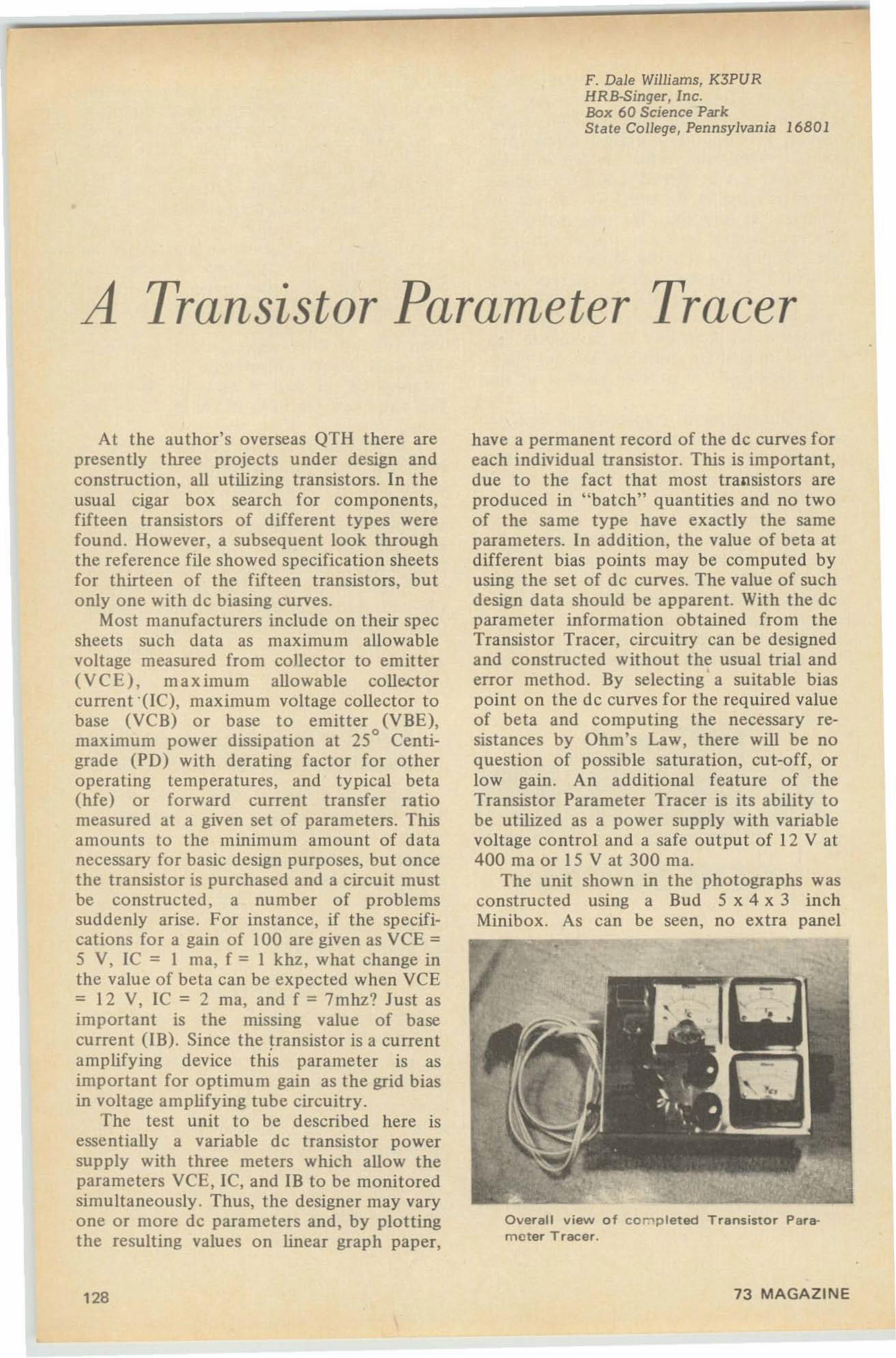
F. Dale Williams, K3PURHRB-Singer, Inc.Box 60 Science ParkState College, Pennsylvania 16801
A Transistor Parameter Tracer
At the author's overseas QTH there arepresently three projects under design andconstructio n, all utilizing transistors. In theusual cigar box search for components,fifteen transistors of different types werefound. However, a subsequent look throughthe reference file showed specification sheetsfor thirteen of the fift een transistors, butonly one with dc biasing curves.
Most manufacturers include on their specsheets such data as maximum allowablevoltage measured fro m collector to emitter(VCE) , ma ximum allowable collectorcurrent '(K'), maximum voltage collector tobase (VCB) or base t o em iller (VBE),maximu m power dissipation at 25° Centigrade (PD) with derating fact or for otheroperating temperatures, and typical beta(hfe) or fo rward curre nt transfer ratiomeasured at a given set of parameters. Thisam ounts to the minimum amount of datanecessary for basic design purposes, but oncethe tra nsistor is purchased and a circuit mustbe construc ted, a number of problemssuddenly arise. For instance, if the specifications fo r a gain of 100 are given as VeE =5 V, IC = I rna, f = I khz, what change inthe value of beta can be expected when VCE= 12 V, IC = 2 rna, and f = 7mhz? Just asimportant is the missing value of basecurrent (IB). Since the transistor is a currentamplifying device this parameter is asimporta nt fo r o ptimu m gain as the grid biasin voltage amplifying tube circuit ry.
The test unit to be described here isessentially a variable dc transistor powersupply with three meters which allow theparameters VCE, IC, and IB to be monitoredsimultaneously . Thus, the designer may varyone or more de parameters and, by plottingthe result ing values on linear graph paper,
128
have a permanent record of the dc curves foreach individual transistor. This is important,due to the fact that most transistors areproduced in " batch" quantities and no twoof the sa me type have exactly the sameparameters. In addition, the value of beta atdifferent bias points may be computed byusing the set of dc curves. The value of suchdesign data should be apparent. With the deparameter information obtained from theTransistor Tracer, circuitry can be designedand constructed without the usual trial and
•error method. By selecting a suitable biaspoint on the dc curves for the required valueof beta and computing the necessary resistances by Ohm's Law, there will be noquestion of possible saturation, cut-off, orlow gain . An additional feature of theTransistor Parameter Tracer is its ability tobe utilized as a power supply with variablevoltage control and a safe output of 12 V at400 rna or 15 V at 300 rna.
The unit sho wn in the photographs wasconstructed using a Bud 5 x 4 x 3 inchMinibox. As can be seen, no extra panel
Overall view of coroptet ee Transistor Parameter Tracer .
73 MAGAZINE
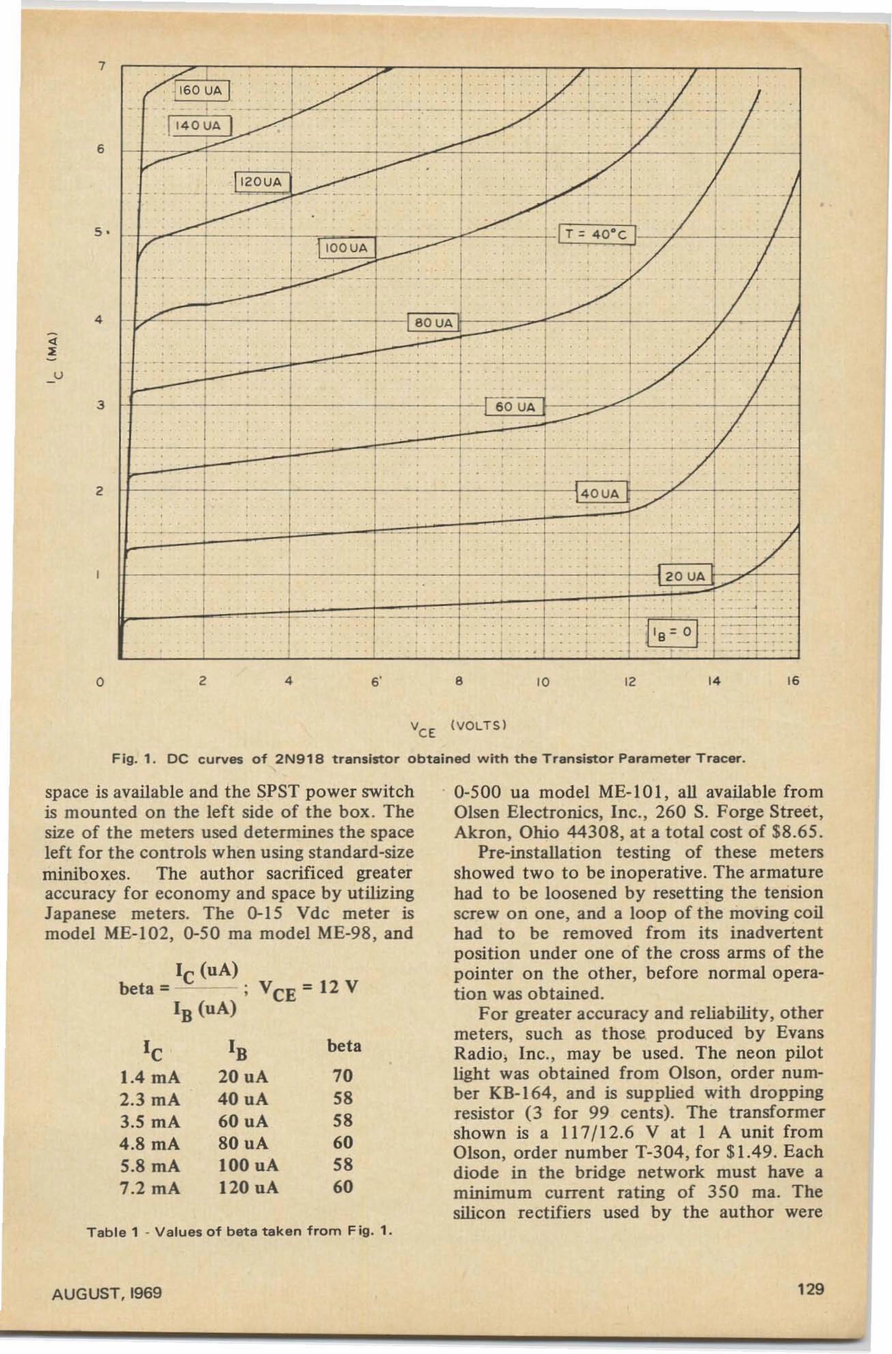
u
7
6
5 •
4
3
2
, ~• ,~. 1 • I ,
/ ~ '60 UA I . .. I ' . . . I• .. · • ' t •
... . . .. ~_. .. ..~-J • . . . - . ,
1' 4 0 UA I .--: : :_. ----
~_.- i---;-- I - . ~ . - ,•I• • , •
•, I , ,
IL•
-I• •
I'2 0VA, •I •
· - . . - . - - . . , . .. • · • .. ·, , , • •
/I I • I I ·. , , IT ~ 4 0·C , II/'
..J110 0 UA • I
, •
J~~ I I• , ,· ... . .. - . . .. . · ·--- , • • • · -
I, , ,
• , , ,, , •• , , • I I
~ V ·
I, , a Q UA
I I ••
-j•
I , • , -~I~ !I ,
· ... _---. - . - - . . - .. . 1. -- - · .. • - _ . .-. . i
I, • I ·, I
I ,I
, ,I• . -
60 UA -, I I,
. .~ I,J .. .
,I I
---~ J• · .
-- -I ,--- . I ~-- - ~ . - - -- --J
• I, · , • I I •
I 1 1 • . ,, ,
. \ 4 0 UA r · • ·, ,./
.J. I I I •• · •
• , •
~j:'1' .• · --1----• ... . . . . - - . - - "---1--'7, I •
I, ,
• •, , • . ,,
i I I I Iao us
I• . · ~- -.
•
i•
, . . - . ·• • • · l ' ..-
I- :--T ""l~-" ~1 - . . _ . 1 _
, ...- -t ... .I .. .. •
l IB~ O' :::_:-:~:::• •
I · . . . . ..• , , • • ..
o 2 4 6' • 10 12 14 16
Fig. 1. DC curves of 2N918 transistor obtained with the Transistor Parameter Tracer.
Table 1 - Valu es of beta taken from Fig. 1.
0-500 ua model ME-IOI, all available fromOlsen Electronics, Inc., 260 S. Forge Street ,Akron, Ohio 44308, at a total cost of $8.65.
Pre-installation testing of these metersshowed two to be inoperative. The armaturehad to be loosened by resetting the tensionscrew on one, and a loop o f the moving coilhad to be removed from its inadvertentposition under one of the cross arms of thepointer on the other, before normaloperation was obtained.
For greater accuracy and reliability, othermeters, such as those produced by EvansRadio . Inc., may be used. The neon pilotlight was obtained from Olson, order number KB-1 64 , and is supplied with droppingresistor (3 for 99 cents). The transformershown is a 117/12. 6 V at I A unit fromOlson, order number T-304 , for $1.49. Eachdiode in the bridge network must have aminimum current rating of 350 rna. Thesilicon rectifiers used by the author were
705858605860
beta
IC (uA)beta; ; VCE ; I2 V
IB (uA)
IB20uA40 uA60 uA80 uA100 uA120 uA
IC1.4 rnA2.3 rnA3.5 rnA4.8 rnA5.8 rnA7.2 rnA
space is available and the SPST power switchis mounted on the left side of the box . Thesize of the meters used determines the spaceleft for the controls when using standard-sizeminiboxes. The author sacrificed greateraccuracy for economy and space by utilizingJapanese meters. The 0-1 5 Vde meter ismodel ME-102, 0-50 rna model ME-98, and
AUGUST, 1969 129
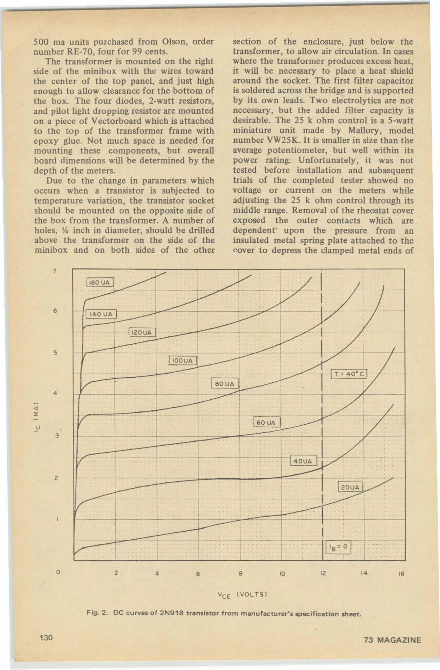
500 rna units purchased from Olson, ordernumber RE-70, four for 99 cents.
The transformer is mounted on the rightside of the minibox with the wires towardthe center of the top panel, and just highenough to allow clearance for the bottom ofthe box. The four diodes, 2-watt resistors,and pilot light dropping resistor are mountedon a piece of Vectorboard which is attachedto the top of the transformer frame withepoxy glue. Not much space is needed formounting these components, but overallboard dimensions will be determined by thedepth of the meters.
Due to the change in parameters whichoccurs when a transistor is subjected totemperature variation, the transistor socketshould be mounted on the opposite side ofthe box from the transformer. A number ofholes, Ii. inch in diameter, should be drilledabove the transformer on the side of theminibox and on both sides of the other
section of the enclosure, just below thetransformer, to allow air circulation. In caseswhere the transformer produces excess heat,it will be necessary to place a heat shieldaround the socket. The first filter capacitoris soldered across the bridge and is supportedby its own leads. Two electrolytics are notnecessary, but the added filter capacity isdesirable. The 25 k ohm control is a 5-wattminiature unit made by Mallory, modelnumber VW25K. It is smaller in size than theaverage potentiometer, but well within itspower rating. Unfortunately , it was nottested before installation and subsequenttrials of the completed tester showed novoltage or current on the meters whileadjusting the 25 k ohm control through itsmiddle range. Removal of the rheostat coverexposed the outer contacts which aredependent' upon the pressure from aninsulated metal spring plate attached to thecover to depress the clamped metal ends of
7
6
5
4
u3
Z
y • ,I1'60 UA!
, • •
I , ,
/ :+ • ,· .. -- -- . . _. . • -
I• II I
• •,
- 1 '40 UA t . _ ..~---
• •I V•
I. • l ,zO UA1 · . . - - ~ . t I• , •, , •
1-,
I kI • I- , , -,• l ,oOUA f •
• , • •• I -. j T~ 40' c l. • . • · ... - :,
180 UA ~V - i •, I I,- , I -:• • •, •
-. • • ..• · · · • !60 UA-! .V • - .
/ • • · •
I, , • •• I I I 1• I•I , I, ,
• ••
IV ~ • · - • - ---• •
• I • .•• I• • 1 Izoud
.•
I,
./'I I•,I ....L I
,• • • ~ - ~ . • •
/' • •
i •I ,
1• , ,,
• , , ,, • • I
,I I I I •
I I, , , . •, , . I• · • · ~ - •
~• - .
i I • , • f/' •1 i, , I · I ...
o Z 4 6 •VeE (VOLT S )
'0 IZ 14 '6
130
Fig. 2 . DC curves of 2N918 transistor from manufacturer's spec ification sheet.
73 MAGAZINE
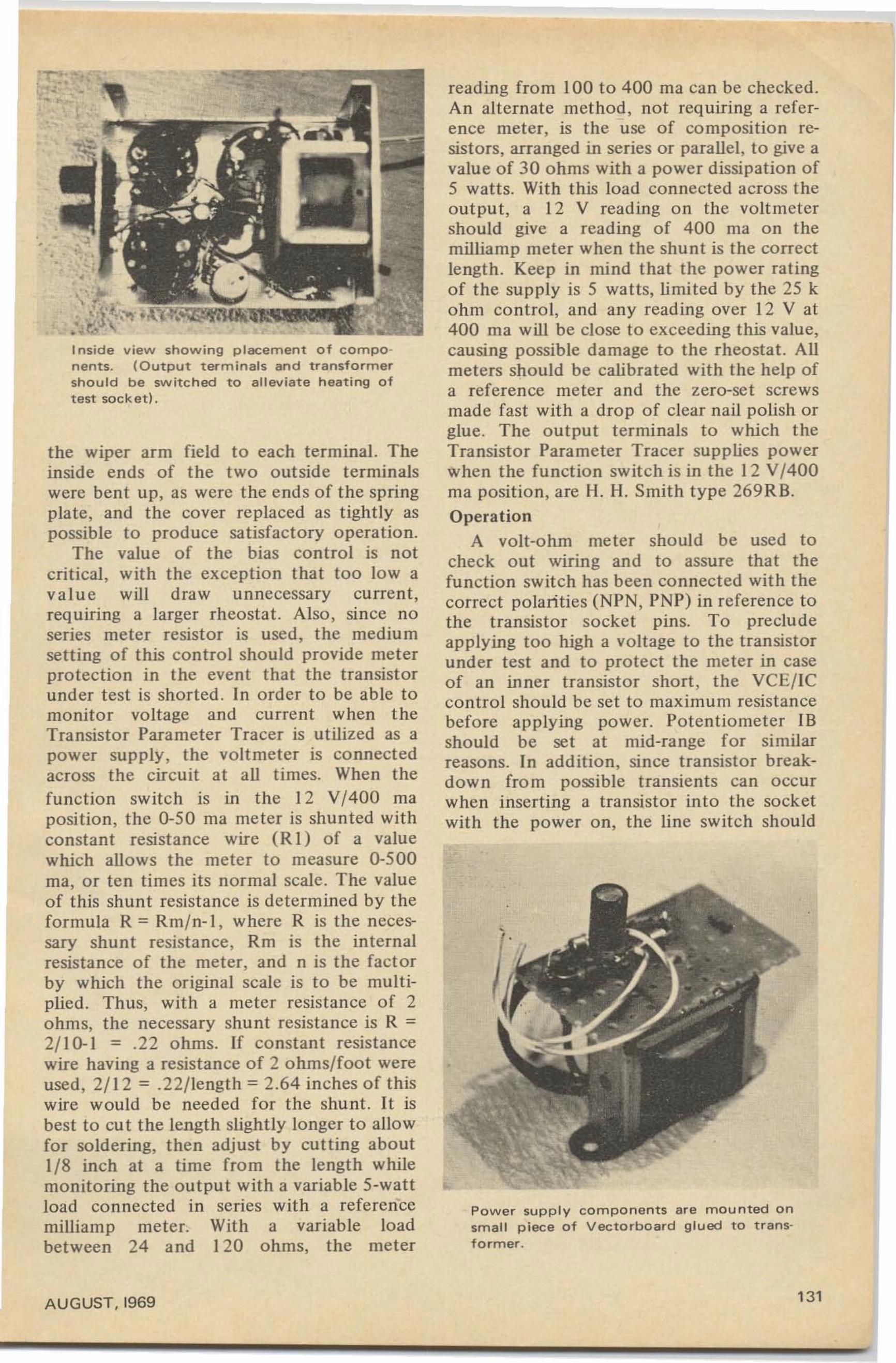
•
I nstde view showing placement of components. (Output terminals and transformershould be switched to alleviate heating oftest socket).
the wiper arm field to each terminal. Theinside ends of the two outside terminalswere bent up, as were the ends of the springplate, and the cover replaced as tightly aspossible to produce satisfactory operation.
The value of the bias control is notcritical, with the exception that too Iowavalue will draw unnecessary current,requiring a larger rheostat . Also, since noseries meter resistor is used, the mediumsetting of this control should provide meterprotection in the event that the transistorunder test is shorted . In order to be able tomonitor voltage and current when theTransistor Parameter Tracer is utilized as apower supply, the voltmeter is connectedacross the circuit at all times. When thefunction switch is in the 12 V/400 rnaposition, the 0-50 rna meter is shunted withconstant resistance wire (R I) of a valuewhich allows the meter to measure 0-500rna, or ten times its normal scale. The valueof this shunt resistance is determined by theformula R = Rm/n-l , where R is the necessary shunt resistance, Rm is the internalresistance of the meter, and n is the factorby which the original scale is to be multiplied . Thus, with a meter resistance of 2ohms, the necessary shunt resistance is R =2/1 0-1 = .22 ohms. If constant resistancewire having a resistance of 2 ohms/foot wereused, 2/12 = .22/length = 2.64 inches of thiswire would be needed for the shunt. It isbest to cu t the length slightly longer to allowfor soldering, then adjust by cutting aboul1/8 inch at a time from the length whilemonitoring the output with a variable 5-wattload connected in series with a referencemilliamp meter. With a variable loadbetween 24 and 120 ohms, the meter
AUGUST,I969
reading from 100 to 400 rna can be checked.An alternate method, not requiring a reference meter, is the use of composition resistors, arranged in series or parallel, to give avalue of 30 ohms with a power dissipation of5 watts. With this load connected across theoutput, a 12 V reading on the voltmetershould give a reading of 400 ma on themilliamp meter when the shunt is the correctlength. Keep in mind that the power ratingof the supply is 5 watts, limited by the 25 kohm control, and any reading over 12 V at400 rna will be close to exceeding this value,causing possible damage to the rheostat. Allmeters should be calibrated with the help ofa reference meter and the zero-set screwsmade fast with a drop of clear nail polish orglue. The output terminals to which theTransistor Parameter Tracer supplies powerwhen the function switch is in the 12 V/400rna position, are 11 . II. Smith type 269 R B.
OperationA volt-ohm meter should be used to
check out wiring and to assure that thefunction switch has been connected with thecorrect polarities (NI'N, PNP) in reference tothe transistor socket pins. To precludeapplying too high a voltage to the transistorunder test and to protect the meter in caseof an inner transistor short , the VCE/ICcontrol should be set to maximum resistancebefore applying power. Potentiometer IBshould be set at mid-range for similarreasons. In addition, since transistor breakdown from possible transients can occurwhen inserting a transistor into the socketwith the power on, the line switch should
Power supply components are mounted onsmall piece of Vectorboard glued to transformer .
131
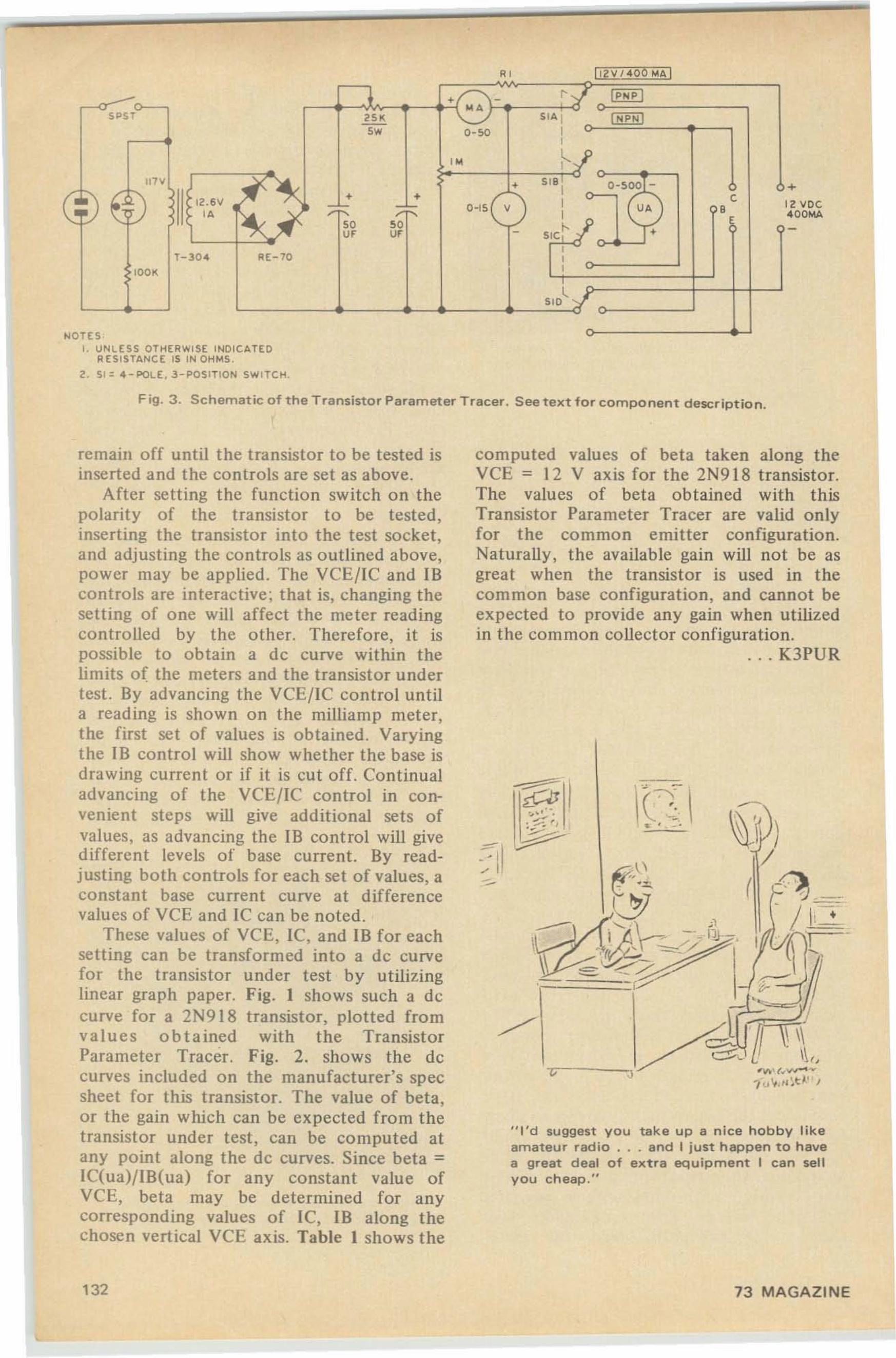
+a VO C
"'OOMA
" ]I ZV/ 400 h4 A I
... /-..... - " '1 I PNP IW '
5"5T '" SIA I [ NPN)5w O-SO I
I
I W ~--J'11''1
f~ • S 18 : 0-5ooj
::::: EI I • • C12.6\'; :;- r- O-IS V I u. S I
IA
~-,~ ~
S IC ~j'50U; U; - T'
1-30 4 A[-70 I
lOO K I
L ISID::c
NOTESf. UNL ESS OTHERWI SE INDICATED
RE SISTANC E IS IN OH MS.
2.51= 4 - POl E, 3 - POSITl ON SWITC M.
F ig . 3 . Schematic of the Trans istor Parameter Tracer. S ee te xt for c o m po nent description .
.. 0'\0 ' (" "..-0 v
-/u ¥,'I~ t l ' J
...--- .)
"I 'd suggest y ou take up a nice hobby likeamateur radio . .. and I just happen to havea great deal of extra equipment I can sellyou ch eap ,"
--
computed values of beta taken along theVCE = 12 V axis for the 2N918 transistor.The values of beta obtained with thisTransistor Parameter Tracer are valid onlyfor the common emitter configuration.Naturally, the available gain will not be asgreat when the transistor is used in thecommon base configuration, and cannot beexpected to provide any gain when utilizedin the common collector configuration.
.. . K3PUR
~I".:... .. -:;". ' ,~.
remain off until the transistor to be tested isinserted and the co ntrols are set as above.
After set t ing the functio n switch on thepolarity of the transistor to be tested ,inserting the transistor into the test socket,and adjusting the controls as outlined above,power may be applied. The VCE/I C and IBcontrols are interactive ; that is, changing thesett ing of one will affect the meter readingcontro lled by the other. Therefo re, it ispossible to obtain a de curve within thelimits o f the meters and the transistor undertest. By advanci ng the VCE/ IC contro l untila reading is shown on the milliamp meter,the first set of values is obtained. Varyingt he IB control will show whether the base isdrawing current or if it is cut off. Continualadvancing of t he VCE/ IC control in convenient steps will give additional sets ofvalues, as advancing the IB control will givedifferent levels of base current. By readjusting both contro ls for each set of values, aconstant base current curve at differencevalues of VCE and IC can be noted.
These values of VCE, IC, and IB for eachsett ing can be transformed into a de curvefor the transistor under test by utilizinglinear graph paper. Fig. I shows such a dccurve for a 2N9 l8 transistor, plaited fromvalu e s o b t ained with the TransistorParameter Tracer. Fig. 2. shows the dccurves included on the manufacturer's specsheet for th is transistor. The value of beta,or the gain which can be expected from thetransistor under test , can be co mputed atany point along t he dc curves. Since beta =lC(ua)/IB(ua) for any constant value ofVCE, beta may be determined for anyco rresponding values of I e , 18 along thechosen vertical Ve E axis. Table I shows the
132 73 MAGAZINE
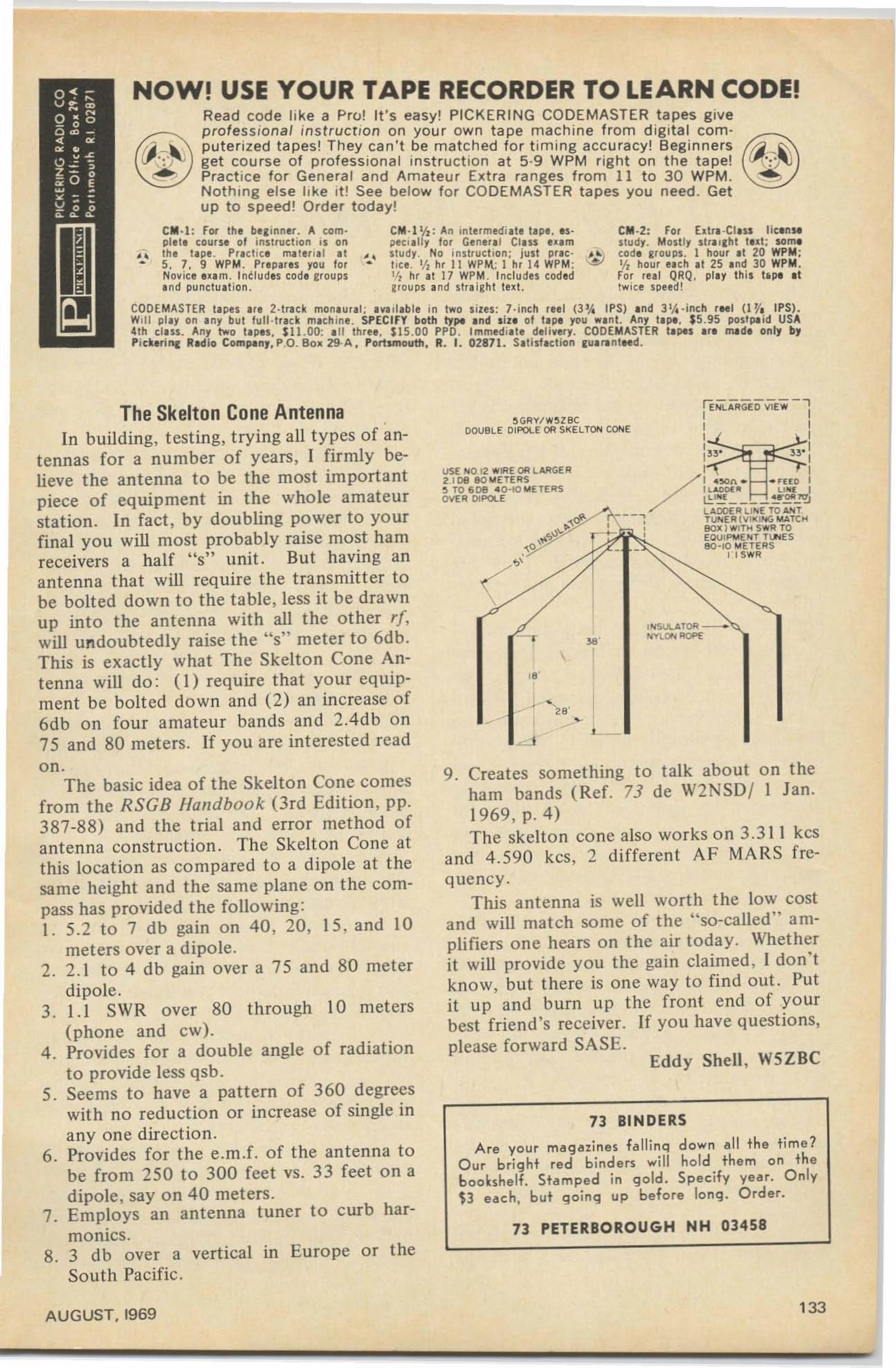
CM·I: For 1111 beginner. A ce rnpl.ll course 01 inatrucfian is on
. , lhe lape . Pracllce maler ial at- S, 7, 9 WP h4 . Pr.pares you for
Novice exam . Inclu des code groupsInd punctuation .
NOW! USE YOUR TAPE RECORDER TO LEARN CODE!Read cc:>de like a Pro! It 's easy! PICKERING CODEMASTER tapes give
~ _ p rofessIo nal instruction on yo ur own t ape machine f rom digital com-(J.:."', putertzed tapes! They .can't be matched for timi ng accuracy! Begi nners ~~
.. / get course of professional instruction at 5·9 WPM right on the ta pe! U'!'•••~~~ Practice for General and Amateur Extra ranges from 11 to 30 WPM: !aC
Nottung else like It! See below for CODEMASTER tapes you need. Get -up to speed! Order today!
eM·I V, : An Intermediate tap. , IS- CM-2: for Edr,-Cl," liCinMpec' all y for Gener, ' elus exam stud, . Mostly sl"'1M lut; someI' study. No instruction; just crec- , J~J code groups. I hour .1 20 WPM ;
• l ice . 1/2 hr 11 WPM..: 1 hr 14 WPM ; ':::::-' lit hour nth .t 25 ud 30 WPM .III hr at I7 WPM . rnclu.:les coded for ree! QRQ, pray tllis IiPI .tgroups a nd straigll! text. twtce speed!
~?I~E~ASTER races lit 2·lrld menaural: IVillable in two Siles: .7.inch reel (J IA IPS) . nd JIA ·incll riel (1¥. IPS).4111 P ay o~ any but lull ·track macll ln!. SPECIFY bot ll tyPi .nd Sill of tlPI yeu want . Any tapl . $5.95 postpaid USAP' kcl~U . R ~~ twco laPis, $11.00: I II tnree . $IS .00 PPD . Immediale deliv!ry. CODEMASTER tlpeS .rl /NIdi onl, b,
I C Inne I 10 ompan,. P.O. BOlli 29-A, Portsmouth , R. I. 02871. Sallsfaction guaranlted.
73 PETERBOROUGH NH 0345B
73 BINDERS
Are you r magazi nes fall inq down all t he t ime?Our bright red binders will hold the m on t heboohhelf. Stamped in gold. Specify year. OnlyU each, but going up before long. Order.
fENLARGEOVIEW - iI II I
Eddy Shell, W5ZBC
133" 33":I I
/
1 .'<In . _FEE D II ......Oot: . I.I" E II!:'~ q'~_'"!J
___., LADDE R L I ~ E TO ANTI' TUNER (VIKIN(; MATCH_+_ : 9011 lwITH SWRTO
EOUIPME~T T....ES90- 10 METERS
IISWR
!>(;RY/W5ZBCDOUBLE DIPOLE OR SKELTON CONE
9. Creates something to talk about on theham bands (Ref. 73 de W2NSD j I Jan.1969, p. 4)The skelton cone also works on 3.3 1 I kcs
and 4 .590 kcs, 2 d iffere nt AF MA RS frequency,
This antenna is well worth the low costand will match so me of the "so-called" amplifiers one hears on the air today. Whetherit will provide you the gain claimed , I don'tknow, but there is one way to find out. Putit up and burn up the front end of yourbest friend's receiver. If you have questions,please forward SASE.
USE NO \2 w~E OR L ARGE R2 .108 8O MEfE R$5 TO 6 08 . 0 -10"'E fERSOVER ()l POLE
The Skelton Cone Antenna•
In building, testing, t rying all types of antennas for a number of years, I firmly believe the antenna to be the most importantpiece of equipment in the whole amateurstation. In fact, by doubling power to yourfinal you will most probably raise most hamreceivers a half "s" unit. But having anantenna that will require the transmitter tobe bolted down to the table, less it be drawnup into the antenna with all the other r[,will undoubtedly raise the "s" meter to Sdb .This is exactly what The Skelton Cone Antenna will do: (I) require that your equipment be bolted down and (2) an increase of6db on four amateur ba nds and 2Adb on75 and 80 meters. If you are interested readon .
The basic idea of the Skelton Cone comesfrom the RSGB Handbook (3rd Edition , pp.387-88) and the trial and error method ofantenna const ruct ion . The Skelton Cone atthis location as compared to a dipole at thesame height and the same plane on the compass has provided the following :I. 5.2 to 7 db gain on 40, 20, 15 , and 10
meters over a dipole ,2. 2. I to 4 db gain over a 75 and 80 meter
dipole.3 . I. I SWR over 80 through 10 meters
(phone and cw) .4 . Provides for a double angle of radiation
to provide less qsb.5 . Seems to have a pattern of 360 degrees
with no reduction or increase of single inanyone direction.
6 . Provides for the e.m .f', of the antenna tobe from 250 to 300 feet vs. 33 feet on adipole , sayan 40 meters.
7. Employs an antenna tuner to curb harmonies.
8 . 3 db over a vertical in Europe or theSouth Pacific.
AUGUST, I969 133
Robert H. Grenell, ex- W8RHR3926 Beech StreetCincinnati , Ohio 45227
What Are we Here For?No government has ever granted any
privilege which was not demanded by themajority of the governed unless it felt that ithad something to gain from so doing. Regardless of idealistic, democratic concepts,rights and privileges are not inherent, but aregranted by those in power . . . or taken fromthem by force of revolution. If the government believes that certain privileges are nolonger necessary or beneficial, it is quick towithdraw or usurp them. To those interestedin the philosphical aspects of governmentalpower, I recommend readings from theworks of Thomas Hobbes and John StuartMill.
How do these rather basic concepts ofgovernmental behavior affect amateur radio?For better or for worse, they affect it verydirectly. The privileges accorded the Amateur Radio Service are no different from
any other privileges granted by the government. The government believes that it andthe country as a whole have somethingsubstantial to gain by the existence ofamateur radio, and with good reason . Tothis self-seeking end, and no other, thegovernment suffers the Amateur Radio Service to exist. Remember that.
Certain things are expected of us inreturn for our privileges, and it has nowbegun to look as though the time isn't faroff when the government will examine Uieperformance and contributions of theAmateur Radio Service to see if we'reholding up our end of the deal. The result ofthat examination is entirely up to us.Whether the Amateur Radio Service willcontinue in its present form, be extensivelycurtailed, or even eliminated depends whollyupon whether the government feels it'sgetting what it wants and needs from ourefforts.
With a TV-watching public convincedthat radio amateurs constitute a marginal,
134
if not detrimental, lunatic fringe of society,and a government which daily gobbles upmore and more individual rights, where dowe stand? In a world clamoring for more andmore space in every dimension including therf spectrum, can we justify the niche weoccupy?
The trouble has already begun. Hams allover the world are aware of the plight ofAnsel Gridley, W4GJ 0, who is being suedfor $1,000,000 because of TVI which theFCC investigators stated was not his responsibility! Despite this statement exoneratingGrid, a court of law entertains this absurdsuit on the grounds of "electronic invasionof privacy." In all probability, Grid will winhis case . .. but only at great expense in timeas well as money. However, if there ever wasa danger signal, this is it.
It's time to take a good look at ourselvesand act on what we see. It looks like about25% of the active amateurs are carrying theother 75 % around ' on their backs. Themoon-bouncers, the phone-patchers, thetraffic nets (the ones that do somethingbesides originating their own messages), andthe emergency nets are doing most of thework of justifying our licenses!
There are those who will say thatamateur radio is a hobby, not a job, and
should be participated in as a hobby. Butjust remember that the very existence of thishobby depends on the patronage of a government which in recent years has becomevery acquisitive of rights and privileges. Sure,amateur radio is a hobby . but it seems thatit's going to take a lot of work to guaranteeits continued availability!
There are three basic jobs which must beundertaken soon if Amateur Radio's survivalis to be assured : (I) We must fully exploitour public service capabilities. (2) We mustfully ex plait our technological ability, andadvance the "state of the art" as we have in
73 MAGAZINE
the past. (3) We must achieve maximumexploitation of OUf activities in terms ofpublic relations.
Wayne Green, W2NSD, editor and glorious leader, has thoroughly hammeredhome the point that what is needed foropeners is an intensive public relations campaign. There simply are not enough of us toform a meaningful pressure group, and wemust , therefore, rely on the public, whichknows little or nothing about us except thatwe occasionally interfere with their TVreception. To get the pu blic on our side andout of neutral and/or hostile corners, wemust acquaint them with the things we'redoing and have done in the past which havebettered the lot of the people as a whole.But most important, we've got to be sure wehave plenty to tell them about ... thingswe're doing now, things we've done in thepast that are affecting their lives now, andhow they benefit now from our activities.
They should know that without amateurpioneering in the vhf spectrum, many thingstaken for granted would not be possible - things like the dependable microwavelinks that cover the entire country withtelevision network programming, and thesimilar microwave links that have madepossible the continually decreasing costs oflong distance telephoning; and the highlyreliable communications between earth andour astronauts in space. They should knowthat amateurs around the world are communicating via moon-bounce. perhaps pavingthe way for a truly global television system,and perhaps o pening st ill anoth er door inthe communication/cost barrier. Perhapsthey should be told that the most efficientmethod of voice communication yet developed, single sideband, is the result ofamateur development and experimentation - but that so rt of thing doesn't reallymean much to the public as a whole.
They should be told that in time ofemergency. a trained group of communicators stands ready to render invaluableassistance. Public offic ials and charitableorganizations should be made aware thathams stand ready to aid them in anyworthwhile project or endeavor requiringrapid and sure communications. We're in theunique position of having to "sell" theservices we want to give away, because too
AUGUST. 1969
few people are aware of our potential ... and sometimes I wonder if even weare fully aware of it. Every parade, boatrace, sports car rally , door-to-door charita blesolicitation, every three-day week-end. provides another opportunity for hams todemonstrate their public service potential - and get it publicized.
How about a rush-hour traffic watch? Ina given city or town, every ham with a rig inhis car could call in traffic and accidentalerts to police and to a cooperating radiostation. The radio station is the kicker.because every time a traffic bulletin comesthrough , Radio Amateurs will get a plug ifthe project is properly set up to begin with.Receivers could be given to the station andto the police to receive the alerts. Proba blyall it would take is for an organized group ofhams to contact a well-rated radio stationand co-ordinate the project with police.Radio stations are constantly looking fornew gimmicks, and this is just as good as theoverworked "copter cop" routine.
Those who enjoy home-brewing canintensify their efforts and truly advance the"state of the art." I don't care what anyonetells you about technology having outstripped amateur techniques; we're the oneswho let it happen while we complacently fellasleep at the switch. You can make abreakthrough; you can develop new techniques and applications. Every month newsolid state devices become available toamateurs. Use them. Experiment. Build. Dosomething.
We are truly responsible for our futures asradio amateurs . Sure, amateur radio is ahobby , but it 's a responsibility too _. at leastunder the present scheme of things. We canmake amateur radio such a powerful toolthat the entire country will be convinced ofour usefulness an d seek out our services .Sure, amateur radio is a hobby . but co mpare it with other hobbies as, for example,pleasure boating on the Ohio river. How longdo you suppose that would last if it weredetermined that it was interfering withshipping?
We're luckier by far than most hobbyists.We have a great opportunity to justify ourexistence. and secure the continuation ofour hobby just by performing. Let's do it.
... ex-W8RIlR
135
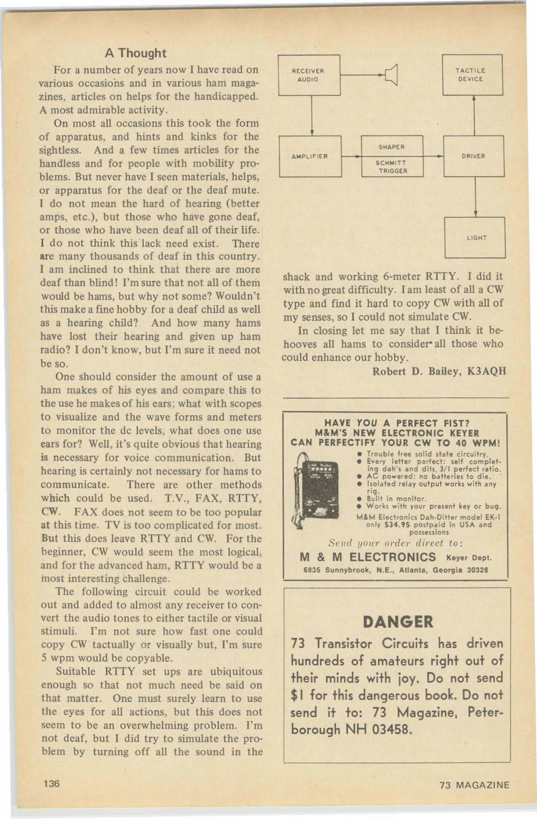
shack and working 6-meter RTTY. I did itwith no great difficulty. I am least of all a CWtype and find it hard to copy CW with all ofmy senses, so I could not simulate CWo
In closing let me say that I think it behooves all hams to consider- all those whocould enhance our hobby.
Robert D. Bailey, K3AQH
DANGER73 Transistor C ircuits has drive nhundreds of amateurs right out oftheir minds with joy. Do not send$1 fo r t his dangerous book. Do notsend it to: 73 Magazine , Peterborough NH 03458,
---•••
,\- ~..... ,~.:'l;,:~,I
II
HAVE YOU A PERFECT FIST?M&M'S NEW ELECTRONIC KEVER
CAN PERFECTIFY YOUR CW TO 40 WPM !• Trouble free solid date circuitry.• Every letter p erfect : self complet
ing dah 's and dits , 1/1 perfect ratio .• AC powered : no batteries to die.• Isolated relay output works .... it k any
rig .• Built in monitor .• W or ks with you r present key or buCjJ.
t.4&M Electro nics Oak-Ditter model EK·'only S34. 95 postpa id in USA and
possessions
S('I u! your order direct to:
M & M ELECTRONICS Ke,e, Depl.6835 Sunnybrook, H.E., Allanla, Georgia 30328
RECEIVER -> TACT ILE
AUD IO "DEV ICE
SHAPE AAIoIP LlF IEA DRIV ER
S CHMITTTRIGGER
LI GHT
A ThoughtFor a number of years now I have read on
various occasions and in various ham magazines, articles on helps for the handicapped.A most admirable activity .
On most all occasions this took the formof apparatus, and hints and kinks for thesightless. And a few times articles for thehandless and for people with mobility problems. But never have I seen materials, helps,or apparatus for the deaf or the deaf mute.I do not mean the hard of hearing (betteramps, etc.), but those who have gone deaf,or those who have been deaf all of their life.I do not think thisIack need exist . Thereare many thousands of deaf in this country.I am inclined to think that there are moredeaf than blind! I'm sure that not all of themwould be hams, but why not some? Wouldn'tthis make a fine hobby for a deaf child as wellas a hearing child? And how many hamshave lost their hearing and given up hamradio? I don't know, but I'm sure it need notbe so .
One should consider the amount of use aham makes of his eyes and compare this tothe use he makes of his ears; what with scopesto visualize and t he wave forms and metersto monitor the de levels, what does one useears for? Well , it's quite obvious that hearingis necessary for voice communication. Buthearing is certainly not necessary for hams tocommunicate . There are other methodswhich could be used. T.V., FAX, RTTY,CWo FAX does not seem to be too popularat this lime. TV is too complicated for most.But t his does leave RTTY and CWo For thebeginner, CW would seem the most logical,and for the advanced ham, RTTY would be amost interesting challenge.
The following circuit could be workedout and added to almost any receiver to convert the audio tones to either tactile or visualstimuli. I'm not sure how fast one couldcopy CW tactually or visually but, I'm sure5 wpm would be copyable.
Suitable RTTY set ups are ubiquitousenough so that not much need be said onthat matter. One must surely learn to usethe eyes for all actions, but this does notseem to be an overwhelming problem. I'mnot deaf, but I did try to simulate the problem by turning off all the sound in the
136 73 MAGAZI NE
Scanning the Flyers
Radio Shack has put out a flyer incelebration of its 46th anniversary. They'vemade it worth your while to celebrate withthem. Like, for instance, a simple receiverfor the low-budget beginning amateur.Thirty-five years ago, he'd have started witha pair of UX-230 tubes in a regenerativedetector plus one-stage audio. Then' radiogot complex and the beginner got leftbehind . Radio Shack has reached out ahelping hand in the form of a kit, at $19.95,that is the modern solid..tate version of thesimple se t that got many young chapsstarted in amateur radio. It's called GlobePatrol.
Parts, though, are the items bargainhunters search for, and Radio Shack hassome at less than you'd expect to pay. A"build-it-box," perf board plus plastic cover,at 59c. Ten 14" jumper leads for 99c (mostother places have gone up to $1.19). A slim3D-wall soldering iron at $1.49 which needsno stand. Two other items are not onlyhandy things to have in the shack but canbe, literally. life savers under certain circumstances. These are master controls for 117· Vac lines. One, at $3 .19, controls threecircuits, each with an independent switchand individual pilot light. The other, whichsells for $3.99, is a master control for sixcircuits, all of which (including the pilotlight) are controlled by a single switch. Amaster control like this can 'save your life ifyou should get tangled up in high voltage,and someone not too well acquain ted withyour shack has to locate a power switch in amatter of seconds. Having seen a friend getkilled on a 117-volt line, I' m a bit touchy onthis subject.
If you want to pursue the subject ofmultiple power outlets in greater depth, Isuggest that you get Waber's 1969 catalog(Waber Electronics, Inc., 2000 North SecondStreet, Philadelphia, PA 10 122). It shows a
comprehensive line, offering such refine-ments as variable voltage, timed on, tim edoff, volt meters, circuit breakers, etc. Thesecan make a neater as well as a safer shack.
It would seem that most wholesale housesbuy their wares from the same source. It'snot often you find an unusual item . . .or oneat an unusual price. Olson Electronicscatalog No. 369 appears to have departedfrom the pattern of universal similarity. Ifound a number of articles that were eitherbelow the customary price or different fro mthe co mpetive run.
For instance, there's a "wired wireless"extension speaker system that would seem tohave almost limitless application possibilities .
Have you ever been tempted to use arocker switch in place of a toggle. ..thenhad second thoughts because of the difficultyof cutting a rectangular hole in a panel?Olson gives you another choice; it offers a"see-saw" switch that looks and works muchlike a rocker , yet mounts in a round (3{4inch) hole like a toggle. These cost 99¢ each.
Tnere are many mini-multi meters. (How'sthat for alliteration?) on the market at veryreasonable prices . Most of these, though,have voltage ranges that limit their use withamateur transmitters, where voltages above1000 are often found. Here, again, Olsonbreaks the usual pattern . Their 20,000-ohms-per-volt multimeter, selling fo r only $7.99.has a top DC range of 2500 volts; on AC, itgoes to 1000.
Tiny electrolytic capacitors compatiblewith small-sized transistorized circuits usually have prices inversely proportional to theirsize. At Olson's, you can buy 10 or 25 mfd25-volt \1," x W' capacitors at five for 99¢.
From these examples, I've concluded it'sworth the time to scan carefully every "flyer"that comes to hand . There are enough hidden bargains to make the practice profitable.
Carl C. Drumeller , W5JJ
AUGUST, 1969
:=:--,
GIANTONLY $24.95
Postpaid
NUi\IBERS-24 HOUR DESK CLOCKCan be read fro m 15 feet in a dense fog.Available in Charcoal Grey, Coral Red, LightBlue, Wh ite or Brown. If you don't speci fywe will send one at rando m. Th ey are allbeautiful. 12 hour movement also available.RED LINE Co., Box 231, Jaffrey, NH·03452
137
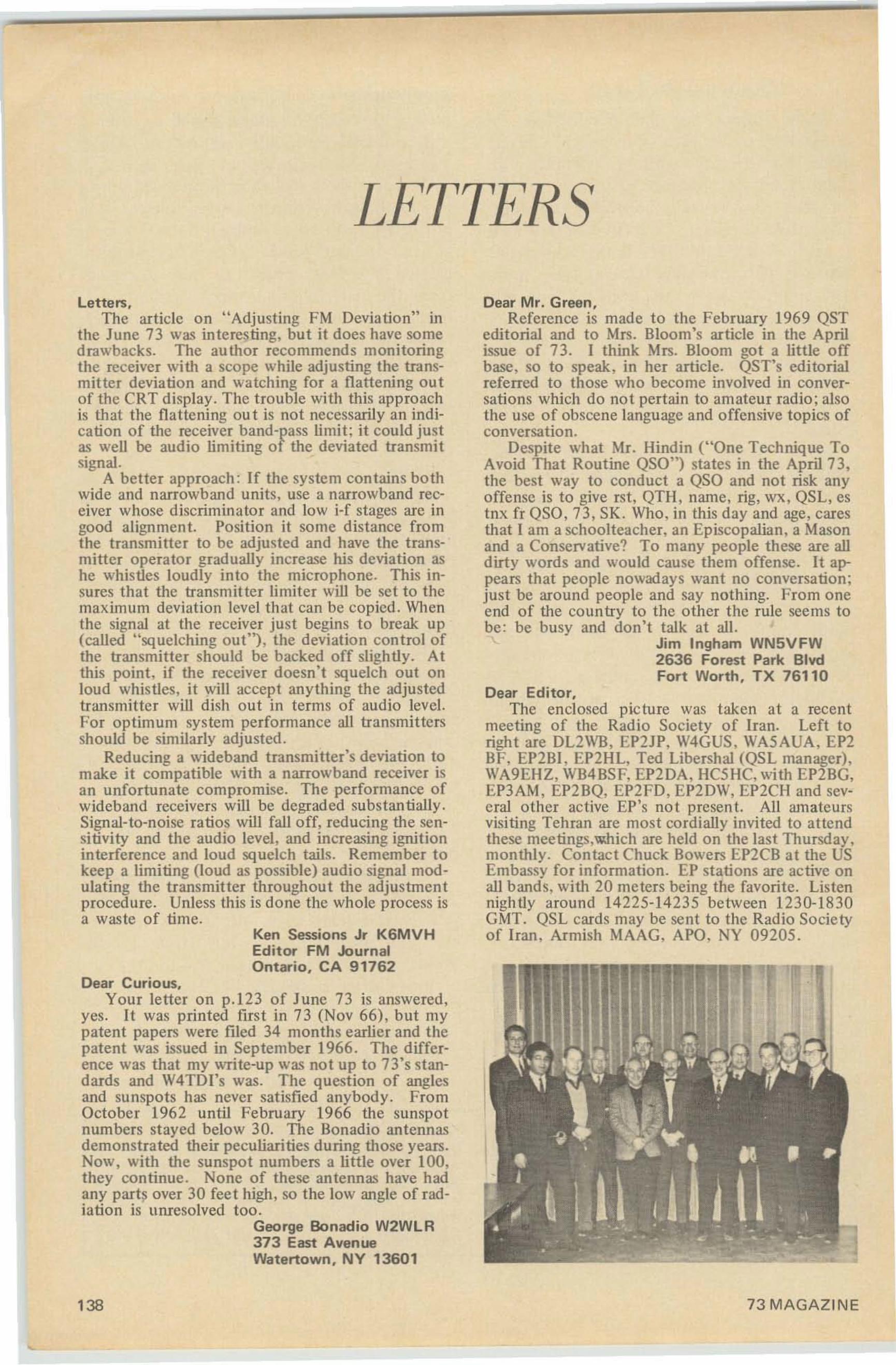
LETTERS
Letters.The article on "Adjusting FM Deviation" in
the June 73 was interesting. but it does have somedrawbacks. The author recommends monitoringthe receiver with a scope while adjusting the transmitter deviation and watching for a flattening outof the CRT display. The trouble with this approachis that the flattening out is not necessarily an indication of the receiver band-pass limit; it could justas well be audio limiting of the deviated transmitsignal.
A better approach : If the system contains bothwide and narrowband units. use a narrowband receiver whose discriminator and low i-f stages arc ingood alignment. Position it some distance fromthe transmitter to be adjusted and have the transmitter operator gradually increase his deviation ashe whistles loudly into the microphone. This insures that the transmitter limiter will be set to themaximum deviation level that can be copied. Whenthe signal at the receiver just begins to break up(called "squelching out") , the deviation control ofthe transmitter should be backed off slightly. Atthis point, if the receiver doesn't squelch out onloud whistles, it will accept anything the adjustedtransmitter will dish out in terms of audio level.For optimum system performance all transmittersshould be similarly adjusted .
Reducing a wideband transmitter's deviation tomake it compatible with a narrowband receiver isan unfortunate compromise. The performance ofwideband receivers will be degraded substantially.Signal-to-noise ratios will falloff, reducing the sensitivity and the audio level, and increasing ignitioninterference and loud squelch tails. Remember tokeep a limiting (loud as possible) audio signal modulating the transmitter throughout the adjustmentprocedure. Unless this is done the whole process isa waste of time.
Ken Sessions Jr K6MVHEditor FM JournalOntario, CA 91762
Dear Curious.Your letter on p.ll3 of June 73 is answered,
yes. It was printed first in 73 (Nov 66), but mypatent papers were filed 34 months earlier and thepatent was issued in September 1966. The difference was that my write-up was not up to 73's standards and W4TDl's was. The question of anglesand sunspots has never satisfied anybody. FromOctober 1962 until February 1966 the sunspotnumbers stayed below 30. The Bonadio antennasdemonstrated their peculiarities during those years.Now, with the sunspot numbers a little over 100,they continue. None of these antennas have hadany parts over 30 feet high, so the low angle of radiation is unresolved too.
George Bonadio W2WLR373 East AvenueWatertown. NY 13601
138
Dear Mr. Green,Reference is made to the February 1969 QST
editorial and to Mrs. Bloom's article in the Aprilissue of 73. I think Mrs. Bloom got a little offbase, so to speak, in her article. QST's editorialreferred to those who become involved in conversations which do not pertain to amateur radio; alsothe usc of obscene language and offensive topics ofconversation.
Despite what Mr. Hindin ("One Technique ToAvoid That Routine 050") states in the April 73,the best way to conduct a QSO and not risk anyoffense is to give rst, QTH. name, rig. wx, QSL, estnx fr 050,73, SK. Who, in this day and age. caresthat I am a schoolteacher, an Episcopalian, a Masonand a Conservative? To many people these are alldirty words and would cause them offense. It appears that people nowadays want no conversation;just be around people and say nothing. From oneend of the country to the other the rule seems tobe: be busy and don't talk at all.
Jim Ingham WN5VFW2636 Forest Park BlvdFort Worth, TX 76110
Dear Editor.The enclosed picture was taken at a recent
meeting of the Radio Society of Iran. Left toright are DL2WB, EP2JP. W4GUS , WA5AUA , EP2BF, EP2BI, EP2HL, Ted Libershal (QSL manager),WA9EHZ, WB4BSF. EP2DA, HC5HC, with EP2BG,EP3AM, EP2BQ, EP2FD, EP2DW, EP2CH and several other active EP's not present. All amateursvisiting Tehran are most cordially invited to attendthese meetings .which are held on the last Thursday,monthly. Contact Chuck Bowers EPlCB at the USEmbassy for information. EP stations are active onall bands, with 20 meters being the favorite. Listennightly around 14225-14235 between 1230-1830GMT. QSL cards may be sent to the Radio Societyof Iran, Armish MAAG, APO, NY 09205 .
73MAGAZINE
VARIABlE FR EQU ENCY A NTENNA SYSTEMSW it h AT U's for 10-1 60 Mete rs Under $50
SHORTWAVE GUIDE
SPACE PROBLEMS SOLVED WITH
JIIYSTICK
Sy racuse, N Y 13219414 Ne ..... castle Rd .
*TWO·WAY*COMMUNICATION CRYSTALS
AMERICAN CRYSTAL CO.PO BOX 2366 KANSAS CITY, MO.
lARGEST ASSORTMENT ofBRAND NAMES
You can save eno rmous amou nts of mo neywhile choosing fro m a complete line of tra nsceivers. receivers, t ra nsm itters etc.WE HAVE EVERYTHING IN HAM GEAR
SAVE MONEY ORDER BY MAilCB Radio Coo. Inc. 89 Aspen Rd.Swam scott Mass. 0 1901 6 17-598·97 00
24 PAG ES crammed with Gov't Surplus Elect ronic Gear-vthe Biggest Bargain Buys in America! Itwill pay you toSEND 25t for you r copy ·-Refu nded with yourF irst Ordarl
SPECIAL PACKAGE OFFER ; BC·645Transceiver. Dvnamoror and all ac cessories, inc luding mount ings. UHF AntennaAsse mb lies. co ntrol box, complete.set of ccrmectcrs, plugs,
~.~ Rec~iver, t~~4.~'5rf'M'C': :" t ~ ~able,~~_plete with 1 1 tubes, Excellent Used $5.95BRAND NEW' including dynamotor .; $9.9EARC-5/T·23 TRANSMI TTER 100· 156 Me.. includes tubes : 2 -832A, 2 ·1625.BRAN 0 NEW, w i t h tubes and crystal $23.50Used, less tubes _ $4.95ARC-5/R·28 RECEIVER 2 -meter superhet, 100 1 56 Mc in 4 c rystal chan nels, complete w ith 1 0tubes, exce llent used $ 2 4.50
SCR-274-N. ARC-5 COMMAND SET HO!'r~u.ncy R.no- Tv". E.".t"nl u _ "'I~."'_ e •• ndRE CEtVERS Com"I.....ll h Tu_ ..._190-550 0:e._ ec..S3 118 se _ 123.1>0 " 1 27. 5 03-6 Me eC·"!>-I& 16.50 19.50 22,506 -1I1 Me•••_ _ ac..55 1.. ,9 5 IT.lIS 21 .501.5 _3 Io'Ic "." , R·2S , _ 19.50 2 1.50TR ......SMITTERS Cornpl I. h Tubft" -&.3 Mc ec...!lT·· ··1 6 .91>..·• •• '18.1I6· ··· ·· .. ······ ·1 1 1.9 &&,3 -TIo'I e 8C 58 6 .9S.. ,. 8 .9!1 12.9ST-1I1 Io'Ie " eC·..S9 1T ,96 19 .!lO 23.&02 ,1 _3 c T-18 , ", 9.9S." 11 .96J - .....C , , T-19,. , .$ 10,SO.. . ,__ , 12 ,50__ ., 169&
aC ,906 f R EO.'\IiE TE R, C av ity Type 1<15 to 235 Me Com l-' Ie te w ot h an·te n "", ma nua l or, m a l ea llh ,a loon ch a . 1S li KE N EW $14,50
TERMS ~itlwr t .j ( ; Dt'posl! with oroer. balance ('. . D. - R-Remmauce III Full ~lI nl tllUnt OrdH 1;'; ,00. All ship.
ments I-' .OB. our wHd IOU.l' . ;:\YC. AU merc nand tse su bject 10p.rlor nit' I ud I,rill' lhlllg t'.
G & G RADIO SUPPLY COMPANY778 Leonard St .• NYC 10013 -- Ph. 212-267-4605
Ed note: Well, Bob, 1 suggest you forget the petition signatures and spend your time putting theproblems and the proposed solutions to them onpaper. Sign it, have it notarized, make 14 copiesand send the works to the FCC. Send me a copyfor 73 too , please. The tim e for signatures is whenthe FCC releases your proposal with a docket n um ber...then it is either supported or not. 1 think youridea is a good one and will be glad to pass alongyour letters in 73. For that matter, even if I disagreed with your proposals I would probably passthem along in 73. Frankly, I wouldn't look for alot of support from the ARRL, though I am always willing to be surprised.
Dear Wayne,I have located the following Wall Street Hams:
Jay Nathan K2HVM, Bioren & Co., 120 Broadway.Joe Re KIZUV, Bear, Steams & Co., 1 Wall Street.Herb Gesell WB2ASA, Stone & Webster, 90 Broad .Rob Robitaille WB20TF, Eastman, Dillon. 1 ChaseHow about a shout from other Wall Stree ters?
Geo rge Gero WA2 FEFFirst Ha nnover Co rp.67 Broad Street , NYC
Robert VVheaton WSP KKRoute 2 , Box 3240San Antonio, TX 78228
Dear Wayne,First let me congratulate you on the last few
issues. I realize that you don't like being editor. butbe assured that nobody can do the job like you doit. I hope you'Il stay this time.
Wayne. I went down last week and passed theExtra and have since done some very serious thinking on the whole business. Naturally I am proud ofhaving passed, but I've discussed a few ideas withfriends on the air and we have reached the conclusion that if phase II of the incentive licensing isimplemented in November the future of our bandswill be very seriously threatened .
The intrusion into our bands of the ever-hungrycommercial is bound to become more pronounced.In my area we are plagued by meatgrinder CW signals on 80M from Central and South Americans.and of course Castro 's sandbar. They are alloverthe band and really thick around 3750-3800, theDX phone frequencies.
Despite many of us giving them hell. their activities have increased noticably during the last twoyears and can't do anything but get worse since somany hams are apathetic about the loss of theirfrequencies. The rejection of the Extra and Advanced Class licenses rather prove this.
We would like to petition the FCC to (I) Restore the bands lost by the General. Co nditional,Advanced and Technician licensees and revert backto the bands as they were before November 1968.(2) Create an incentive by opening a new phonesubband in the 80 and 20M bands, at least, with25 khz for Extra and 50 khz for Advanced as areasonable, but minimal incentive.
Having passed the test. I think I'm in a goodposition to ask for a change back. I feel that itwould be foo lish to continue and that our primeconcern should be to save our frequencies. I challenge anyone to prove that there has been any reduction of lids or profanity on our bands...or anyother major improvement as a direct result of incentive licensing.
AUGUST. 1969 139
, 1•
•
..:J
"'-•
Dear Wayne.You might be interested in some portable oper
ating I intend to do during the first two weeks ofAugust on a trip through Central America. HK , YV,Trinidad, the Leeward and Windward Islands, KP4.South Caicos and the Bahamas. I will probablyconcentrate on 75M to give more of the fellowsnew countries on that band. I always enjoy 73 andlike your style very much. Keep up the good work.
Charles Crow WB4MKU1211 27th Place SouthBirmingham. AL 35205
Dear Wayne,For some time you have been sounding off on
the importance of getting new hams and I agreethat the situa tion is serious. Our local club, theTwin City Hams, in cooperation with the local college, has just completed offering a course leadingto a Novice license (no college credit). I must saythat we were amazed at the number of people whowere interested in becoming hams. We had over100 people attend and expect over 30 new Novicesin the near fu ture.
Record my vote for the new system of indicat-ing propagation conditions.
William Gulledge K5UA R700A Plum StreetMonroe, LA 71201
Dear Editor,Your May issue was so good I can't express it in
words, There were 40 (count them 40) ~reat arti cles. I especially liked "In The Beginning. ' It oughtto win the Pulitzer Prize for comedy! If you havemore articles like that I might become a Life Subscriber. Say, if you need a photo to fill some spaceyou might use the enclosed , I expect to have anarticle on working DX ready for you soon.
Donald Rubin WA3JRA
--0;' , »-//~/.R~du~~' Iftl.. l~f~n,~ .nd , • or All Amateur Tr.mmi"erl,'OI~ 011 All "likes Shou w..~ G .... I '000 W PR", ~,y," "lIkU Wo rld-\1'- Id~ u .r."., or attl ow·R", ~ p"on Sffo nJ~1 ('omeJ~1O Itt' . lIght, Nut. Weatherproof.", IlII " 6 II n o il'll f.~dl!n ~. S...lod rno nl !flpt For no.... I nd I II 011....d oo. ....I~U"· lO h mlln S ~l'It'" In\rn , ", n il brl1U ~Ifor","n.c~ J Ulrl nlndR~o-2o- l S· 1 0 ~trr bind•. ('O pl~l~ IO~ fl SII1 I1 S 4o-20·1S· IO m.... blnd•.S"- h ( h~.. lo r "'or ld · "" d~ Ihorl ~ ..,,~pl,onl SII.' S . SOlid ....Il B ,OO ("..h.ck. '110) Ind I'I Y 1'0'1'11'" bill. n" 100 plul PO'la ~O on 1!T,nl or ..n luU P"" rorPOU·f "'d d.h• .,y I'omplo,o ,n"'llel,onl lndud~d
"'E S ER'" ELECTRONI CS 0 . ,,1 A "'urntv. N~b...k. 68847
AND. LM. ETC.Pp·l06 U: Metered , Knob -adjustable 90 ·270 II upt o 80 m a d e ; also select an AC of 6 .3 II SA , o r 12 .6\I 2 '/, A o r 28 II 2 '/. A . With mating output plug &all t ec h d a ta . S hpg w t 50# 19.50BARGAINS WHICH THE ABOVE WILL POWER :lM·(-) Freq . Meter : . 12 5 -20 mhz•.01 %, CW orAM , w it h serial -matched c a lib. ecce . tech . data,m at in g plug . Checked & grtd 57.50TS-323 Freq. Meter : Similar to above but 20·480mhz ..001 %. With data 169.50TS·175 Preq . Meter : 85·1000 mhz 75.00A.R .C. RllA : Mo dern ose- 190·550 khz 12.95A.R.C . R22 : 54 0- 16 00 khz w /tuning graph 17.95A.R.C . R13B : 108·132 mhl w /tuning graph.27.50
HI-SENSITIVITY UHF RECEIVER375·1000 mhz . Stoddart RFI Meter NM-50Awith pwr. sply, c o rd s, dipole holder , 3 pair dipoles. Input 50 ohms. IF 60 rnhz . Bandwidth I mhz at 370 and 1.8atlghz RF. Image& souetous.resconse reject . better than 40 d b .Sensit . as a 2 ·terminal tuned ...oltmeter is 10 u ...;will be less with I-pair dipole . but you can makean array to bring it up . If the vorteae-ereeouation cenb. charts didn 't get lost it would beworth $1 .250 in surplus , $2,852 from thefactory . .. . . so we will sell it as a simple rece i...er in grtd-excel. condition for only .. . $275
ULTRA-WIDE·BAND RECEIVER :AN /ALR-5: Late post war AM /FM Countermeasuresrcvr . lias S-Meter: variable IF Atten . & passband (0.2 or2 rnhz from 30 mhz center): AF. Video & Pan. outputs.New, modified for 120 v 60 hz . includes new ( Method IIpack ) 4 -band plug-in converter .038· 1 ghz, 4 Type-Nplugs automatically select correct an t. as ba nds are switch ed . Sensu . at -6 db sett ing: 6 \11; uv thru 132 mhz , . 13thru 780 mhz & 45.112 at I ghz . BRAND NEW , with book& mating pwr-Input plug , only 275 .00
VERSATILE PLATE & FILAM. TRANSFORMERDegot Spares for SP·6OQ·JX : Pri. 9 5 / 10 5/ 117/ 13 0119 12 1012 3 4126 0 \I 5 0 / 6 0 hz _ Sec . 1 : 305·0-305v , 150 rn a . S ec . 2 : 5 v 3 A . Sec . 3 : 6 .3 \/ 5A.Sec . 4 : 7 Y. v , 3/4 A . S ec . 5 : 7 Y. \I , 1 % A . Leqendfor pi ns is pl ai n ly marked . Herm. sealed 2.95
•FOUND! A NEAT & COMPACT SCOPE XFRMR!Freed 12691 : OAS Loran S p a res, supplied 5 " CA ,plates & h t rs. Pri. 105 ·130... 50/60 hz . S ec's. insu1.5 k v 1490 & 1100 v , 5 rna ; 390·0·390 v 100 rna ;el ec tro.s1a~ic a ll y.~h ie lded 6 .3 v , 0 .8 A ~ t wo 2 Y' .\I.J..2A. Sec 5 , IOSUL 1 Y. k... : two 6 .3 v , 6 A. 5 v, 3 A. ,L Y.v . 5 A . Case 5%x5x7'4 . W ith di agra m . S hi pped
nl b co llec t R EA Express 2.95
FAIRCHILD SOUD-STATE SCOPES all w/cuet trace plug -ins 25 & 50 rnb z, w /delayed time-basep lug ins . w /boo k s. o ver h a u led & grtd . As lowas _ 825.00We probably have the best inventory of good labtest equipment in the country . But. please do notask for cetetoqt Ask for specific items or kinds ofitems you need! We also buy I What do you have?
••• •
CUSTOM TRANSFORMER DESIGN ," MANUFACTUREwrne tooa)' for a fr.... quota tton on any t ransforrntr. ('hoke.or sl(u rable·4'e8Nor. El r h uni t \0'111 be lI ..,l ltnl'd and manufarlll r..d to )'01.11 norl Ii pl'dfirat lonl. ~\lndard }o; ·1 and ta pewound . 'C.. cores are availahle. Quantl t ies f rom stnete unlllto produc tion r uns may ho accommodat ed.
PETER W. DAHL CO .5325 Anne"' A...~. • EI Puo, Tu u 79924
Tel . : 9 15·751·4856
Dear Wayne.Yeah, I'm mad, but not at 73. I think that the
ARRL is going to wipe out ham radio for all butthe ham who works in electronics or the hobbyistwho is willing to spend all of his time studying.
To build up their advertising the QST boys haveplugged for licensing everyone. Now they want to
140 73 MAGAZINE
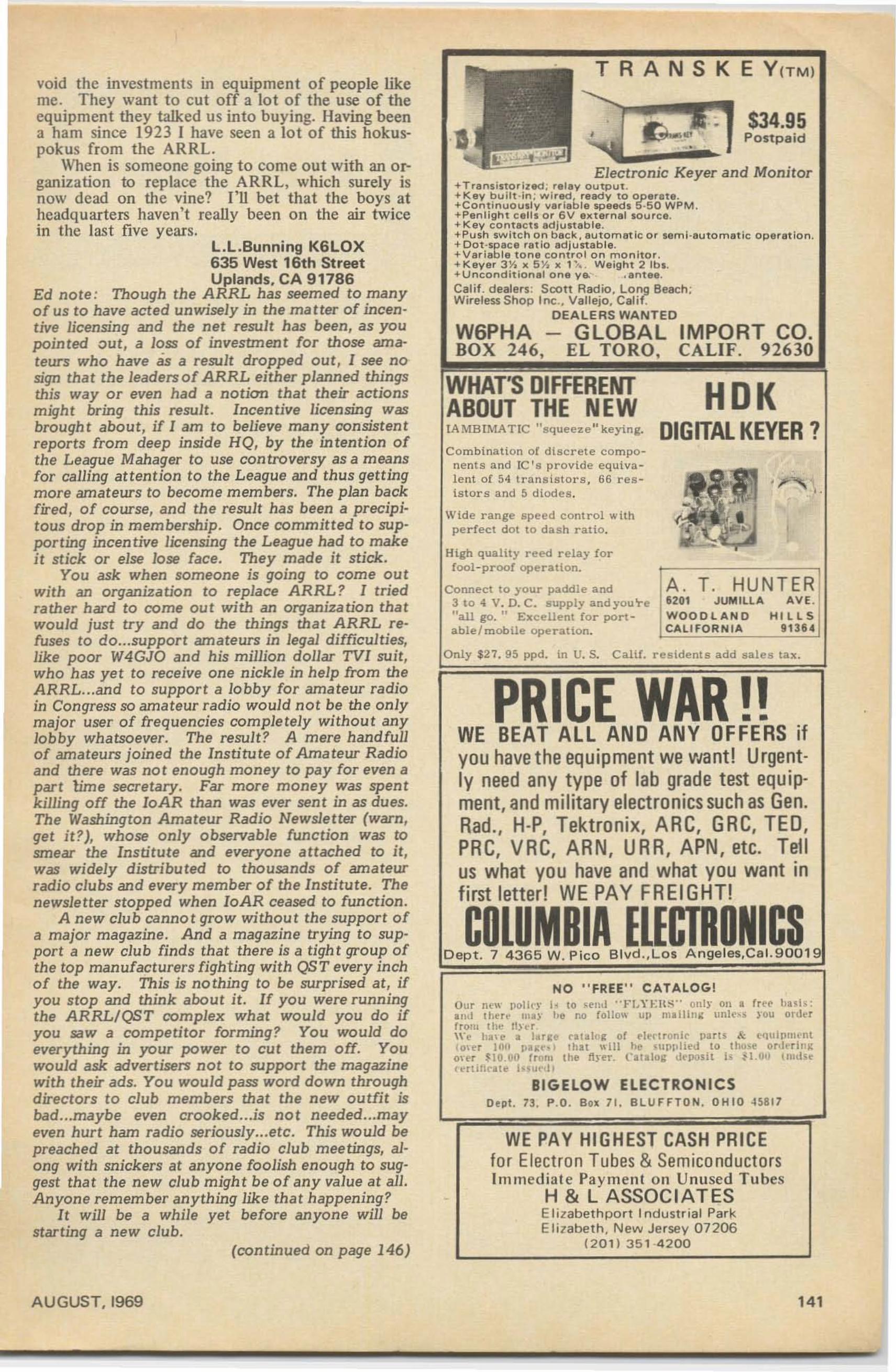
--- -- - ---
$34.95P o st p a id
A. T. HUNTER620' JUMtLLA AV E"WOO D LA ND HILLSCALIFO R N IA 91364
HOKDIGITAL KEVER?
T RAN S K E Y CTM)
Electronic Keyer and Monitor.T,ans;storizltd ; relav o u t p u t .+Key b uilt ·;... ; w i red, re ady 10 operate.+Contlnuoully vlIriable speeds 5 ·50 WPM.+Penlight cells o r 6V 8Kternal sou r ce.+ K e y contllctllldjuitable.+Push switch on back, au tomatle o r semi ·automatic ope, a t ion.+ Do t -spa c e ,all0 adjustab le.+Va, lable tone ecnt-or on monitor,+ Keye, 3 1'1)( 5 Y. x 1··•• Weight 2 lb• .+Uncondit ional one ya... . e n t e e .Calif . dealers: SCOtt Radio. Long Beach ;Wireless Sho p Inc .• Vallejo, Calif.
D EALERS WA N TE D
W6PHA - GLOBAL IMPORT CO.BOX 24 6, EL TORO, CALIF. 92630
WHAT'S DlFFEREIIITABOUT THE NEWIA MBIMATIC " s qu e e z e" ke yi n g.
C ombination of d i s c r e t e components and IC ' s p r ovide equi valent of 54 t r a nsistor s , 66 re s Is tor s a nd 5 diodes.
Wide r ange spe ed control wi thpe r fect dot t o da s h ratio.
High qua lity r e ed r elay forfool -pr oof operation.
Connect to your paddle andJ t o 4 V. D. C. supply and y ou're" all go." Exc e lle nt for port able /mobile oper-atton.
WE PAY HIGHEST CASH PRICEfor Elect ron Tubes& SemiconductorsIm med iate Paymen t on Unused T u bes
H & L ASSOCIATESE lizahethport Indust r ial ParkE lizabeth, New Jersey 0 7206
(20 11 35 1 ·4 20 0
NO " FREE" CATALOG !Our new polk)" I_ 10 ,end 'TLY EH :-;"' only on a rree had,:am) the re m~)" he no folio" ' up Illil linll unh',s )"OU orderf rom Ill,· ttycr ," 'e h~'e a IKTg(' ntalog of elect ronic IlarlS « O:'1ul plllt"nt(Ol l' f 1011 l'aJ;l" l thl t will be "lJll,lleti 10 l ho, f' or,krlngover ~lO"OO from lhe "'-('1". ('atalol: deposit is il.Uu tlmls..{'l'rtillrate h,U\',)1
BIGELOW ELECTRONICSn ept . 73. P ,O. BOl 71 , BLUFFTON . OHIO 4581 7
PRICE WAR!!WE BEAT ALL AND ANY OFFERS ifyou have the equipment we want! Urgently need any type of lab grade test equipment, and military electronics such as Gen.Rad. , H-P, Tektronix, ARC, GRC, TED,PRC, VRC, ARN, URR, APN, etc. Tellus what you have and what you want infirst letter! WE PAY FREI GHT!
COLUMBIA ELECTRONICSDept. 7 4 3 6 5 W. Pico Blvd., Los Angeles ,Cal.9001 9
Only $2 7. 95 ppd . in U. S. Calif. r e s ide nt s a dd sales tax .
L.L.Bunning K6LOX635 West 16th StreetUplands. CA 91786
Ed note : Though the ARRL has seemed to m anyof us to have acted unwisely in the matter of incentive licensing and the net result has been, as youpointed out, a loss of investment for those amateurs who have as a result dropped o ut, I see nosign that the leaders of ARRL either planned thingsthis way or even had a notion that their actionsm ight bring this result . In cen tive licensing wasbrough t abo ut, if I am to believe many con sistentreports from deep inside HQ, by the intention ofthe League Mahager to use controversy as a m eansfor calling attention to the League and thu s gettingmore amateurs to becom e m embers. Th e plan backfired, of course, and the result has been a precipitous drop in membership. Once commit ted to supporting incen tive licensing the League had to makeit stick or else lose face. They made it stick.
You ask when someone is going to come outwith an organization to replace ARRL? I triedrather hard to come out with an organization thatwould just try and do the th ings that ARRL refuses to do...support amateurs in legal difficul ties,like poor W4GJO and his million dollar TVI suit,who has ye t to receive one nickle in help from theA R RL...and to support a lo bby for ama teur radioin Congress so amateur radio would n ot be the onlymajor user of frequen cies completely without anylobby whatsoever. The result ? A m ere handfullof ama teurs joined the Institute of Amateur Radioand there was no t enough money to pay for even apart lime secretary. Far more money was spentkilling off the IoA R than was ever sent in as dues.The Washington Amateur Radio Newsletter (warn,get it?), whose only observable function was tosmear the Ins titute and everyone a ttached to it,was widely distributed to tho usands of amateurradio clubs and every member of the Institu te. Thenewsle tter stopped when IoAR ceased to function .
A new club cannot grow without the support ofa major m agazine. And a magazine trying to support a new club finds that there is a tight group ofthe top manufact urers fighting with QS T every inchof the way. This is nothing to be surprised at , ifyou stop and think about it. If you were runningthe ARRLIQST complex what would you do ifyou saw a competitor forming? You would doeverything in your power to cut them off. Youwould ask advertisers not to support the magazinewith their ads. You would pass word down throughdirectors to club members that the n ew outfit isbad...maybe even crooked...is not needed...mayeven hurt ham radio seriously...etc. This wo uld bepreached at thousands of radio club meetings, along with snick ers at anyone foolish enough to suggest that the new club might be of any value at all.Anyone remember anything like th at happening?
I t will be a while yet before anyone will bestarting a new club.
(con tinued on page 146)
void the investments in equipment of people likeme. They want to cut off a lot of the use of theequ ipment they talked us into buying. Having beena ham since 1923 I have seen a lot of this hokuspokus from the ARRL.
When is someone going to come out with an organization to replace the AR RL, which surely isnow dead on the vine? I'll bet that the boys atheadquarters haven't really been on the air twicein the last five years.
AUGUST. 1969 141
UNIVERSAL LOGICCIRCUIT CARDS
•Instant logiclll for 10 pin TO-5 or 14
lead dual in-line INTEGRATED CIRCUITSThese boards are the most useful items we haveever offered for breadboarding with low cost integrated circuits. The cards are made from 1/16"G-l0 Glass Epoxy, with pads for 14 lead dualin line mounting pads on one side and 10 leadTO-5 pads on the other. 8 lead TO-5 canswill mount in the 10 lead TO-5 pads also. Discrete Transistors and components can be mounted in the locations between the l.e:5, powersupply leads are already routed around the board.Our competitors charge $9.50 each for circuitcard and mating connector.We give you a surplus. unused p.c. board withcomponents on it (that you can keep for yourjunk boxl. a connector and its mate, and ourgreat circuit card. You drill out the desired holepattern, unsolder the connector from the surplus card and install it on the new card, wirein the I.C. 's and compute. A few minutes ofyour time, and you save over 80% of the costof comparable p.c. cards. Get enough for yourbreadboarding needs now because these aregoing to go fast .
2 Cards & matg.conn'tors 2 ICCC $ 2.50 ppd.10 Cards & matg.conn'tors 10 ICCC $10.00 ppd.
100 Cards & matg.conn'tos 100 lax: $88.00 ppd.
MAGNETIC MEMORY ORlIVIThis memory drum originally cost the government over $6,400.00, and is a truly fantasticpiece of equipment. It was made by HughesAircraft Co. as part of an aircraft computer.The unit is completely sealed and thereforethe drum surface is in excellent condition.It has 146 heads mounted in 11 columns, 12 arephase adjustable timing heads, the drive motorrequires 115 VAC 400 cvcle (Hz) 150 VA, andhas a speed of 800 RPM. SH . WT. 50 H.MMD-59. $100.00
EnterprisesPO BOX 44. HATHORNE MASS.
01937
142
* Price-$2 per 25 words for non-commerclol ads; $10per 25 words for business ventures. No display adsor aqency discount. Include YOllr check with order.
.. Deadline for ads is the 1st of the month two monthsprior to publication . For example: Januory lst Is th.deadline for the March Issue which will be mailedon the 10tft of F.bruary.
* Type copy. Phrase and punctuate exactly as you wishit to appear. No all-capital ads.
* We will be the judqe of suitability of ads. Our responsibility for errors extends only to prlntinq a correct ad in a later issue.
* For $1 extra we can maintain a reply box for you.•* We con not check into each advertiser, so CaveatEmpt9r • . •
NEED A VARIABLE CAPACITOR for that homebrew project? We may have what you need at morethan 50% below regular amateur net . Send for freeflyer. A.R.C. Sales, 181 E. Wilson Bridge Rd.,Worthington, Ohio 43085.
3 PLASTIC HOLDERS will frame and protect 60cards, $l-or 10 holders $3. Prepaid & guaranteed.Patent 3309805. Tepabco, Box 198N, Gallatin,Tennessee 37066.
SPECIAL CLOSE-OUT SALE. Rectifiers, Transistors, and many other Electronic Parts. Lowest prices. Send 1St for Catalog. Electronic ComponentsCompany, P.D.Box 2902 S., Baton Rouge, La.
FOURTH ANNUAL Mini·Hamfest, sponsored bythe Rockford Amateur Radio Assn ., August 17,1969, at the Boone County Fairgrounds in Belvidere, Illinois. Lunch and refreshments.
,
RTTY GEAR FOR SALE. List issued monthly, 88or 44 mhy torroids 5 for $2.50 postpaid. ElliottBuchanan & Associates, tnc., 1067 Mandana Blvd .,Oakland, California 94610.
"TOWER HEADQUARTERS'" 11 8rands! Heightsaluminum 35% offl Strata Crank-ups-tow costlRotors, antennas and gear discounts. Phone patch$11.95. Catalog-20t postage. Brownville Sales Co.Stanley, Wisconsin 54768.
SB·34 TRANSCEIVER and SB-2 mike $245. RCAFleetone 12 volt, 60 wan FM mobile on 52.525mhz, $110. Alan Rutz, RR2. LaPorte, IN 46350.
73 MAGAZINE
POLICE/FIRE Dispatcher Directories. Call signs,frequencies; most areas available. Exclusive officiallistings. Stamp brings catalog. Communications,Box 56-ST, Commack, NY 11725.
ELECTRONIC TEST and Communications Equipment - Bargains galore. Send 25 cents for catalog.Palen Electronics, Box 1536, San Mateo,CA 94401.
MAYDAYEMERGENCY MAYDAY
GO MOBILE 115V power inverter. Low cost boat,auto, camping. I n reverse becomes a battery charger. Plans $1.50. Ken Electric, 922 S. Toledo, Tulsa,Oklahoma 74112. •WRL'S USED GEAR has trlal-terms-quaranteelKWM·1 - $249.95; HW-12 - $89.95; Swan 250 $249.95; Galaxy 5mk2 . $279.95; Galaxy 300 $139.95;SBE34 - $289.95 ; R4A - $319.95; Invader 200 - $249.95; HQ1BOAC - $349.95; CE1ooV$259.95; AF68 - $49.95. Many more. Free "bluebook' list. WRL, Box 919, Council Bluffs IA 51501
POWER SUPPLIES $3.98. Nixies $5. Counter $2.$1 packages: capacitors, thermistors, zeners. Popular miniature sizes. Catalog. Murphy, 204 RoslynAve. , Carle Place, NY 11514.
THE ANNUAL HAMFEST for the Washington DCmetropolitan area, sponsored by the FoundationFor Amateur Radio, will be held at the Gaithersburg Fairgrounds in nearby Gaithersburg, Marylandon Sunday September 21st, from 1000 until 1700.
THE FRRL SWAP N SHOP Hamfest will be heldAugust 24 at Phillips Park, Aurora, Illinois. Freecoffee and doughnuts from 9-10 AM . Fun for thewhole family . Homing freq . 145.35 and 3.940 me.For additional info contact Roger Louks, P.O. Box93. Plano. IL 60545.
DANVILLE HAMFEST - August 31. KickapooPark, near Danville, Illinois. Advanced Registration $1. Tickets and information available fromK9CDD. 508 W. Woodlawn. Danville. IL 61832.
THE SHAWNEE Amateur Radio Association willhold a hamfest Sunday, August 3rd at Herrin CityPark in Herrin, Illinois. Trading, prizes. TicketsBill Johnson. 502 Kennicott, Carbondale, IL 62901
TELEPHONE DIALERS 121 Prestodial. Stores 36telephone numbers and automatically dials anyoneat push of a button. New@$119. Richard JacobsWA0AIY. 4941 Tracy. K.C.• MO 64110.
WARA 12th annual Hamfest, Sunday August 24th,Newton Falls Community Center, Newton Falls,Ohio. Take Ohio Turnpike to exit 14 and 'ask formap to Hamfest. Prizes, XYL activities, Swap andShop. For further information write W8VTD, Box809, Warren, Ohio 44481.
WANTED - a used I nstructograph with tapes.K8UZG H Crawford, 302 Going, Pontiac MI 48058
THE EAST COAST VHF SOCIETY 11th annualfree outdoor picnic-hamfest will be held Sunday,August 10, at Saddle Brook Park (NJ) starting at10 AM . Write Box 1263, Paterson, NJ.
AUGUST.1969
DOCTOR'S ORDERSMUST QUIT BUSINESS
JUNK for sale, a large assortment oftest sets, power supplies, amplifiers, med ·ical electronics, originally bought for stripping purposes. but didn't get to do.CASH and CARRY. only.
Sorry, NO Mail Orders accepted.
lOt per pound, plus lOt each tube. and50¢ each meter.
SPECIAL DISCOUNTSAll items advertised since January 1968in HAM RADIO and 73. and listed in my"GOODIE SHEET" for May 1968 andFeburary 1969, except the above "JUNK".co-ax connectors, co-ax cable. and thefew items previously reduced, from myalready low prices:
FOR SALES OF
$10.00 and up a discount of 5%$50.00 and up a discount of 7 1;1 0/0$100.00 and up a discount of 10%
It may pay for a group to get together,or a club to pool their orders. shipmentto one address only. no split sh ipments.to take advantage of the h igher discount.
Discounts only apply on mail orders. orsa les at the store.
Saie ends on August 16. PLEASE in
clude sufficient to cover postage, orother shipping charges. For heavier shipments, please specify routing - REA.motor freight, or bus express.
Sorry, NO more Hamfests.
STORE HOURSMonday thru Friday, 9:30 a.m.-4:30 p.rn.
Saturday, 9:30 a.m.-2:30 p.rn,
B C ElectronicsTelephone 312 CAlumet 5-2235
2333 S. Mic:higan Ave. Chic:ago, Illinois 60616
143
3 INPUT DUAL AND GATEBra nd new factory marked and packagedPHILCO·FORD IC·s. Flat pack, long leads, eachnested in its own plast ic protect ive snap-lidshipping pack. 3 input dual AND gate. Wefurni sh circuit diagram and lead connections .A real bargain f or factory first-line material.
# 69·100 3 for $1.00; 12 for $3.00
GRAB BAGIC's
M ixture untested IC's, flat pack. dual in li ne,TO-5. Most factory ma rked. Package of 12u ru t s WIl O pages RTL and DTL specs. $2.00
Customer pays all shippingNew catalog # 69 now ready
Send 25¢ handling & postage charge.
VARACTOR SIMILAR TO MM060AGood for 40 watts at 432 MC , ea. tested in circuit, w jdiagram for 432 MC tripler. $5.00 ea.
FOR SALE: Heathk it-sized home brewed linear.Four 811 's in G-G. Commercial grey Pref . Cabinet .Excellent construction. Schematic. 1 KW CCS.E:.xtra tubes. $125. Drake 28 with 280 speaker/Omultiplier console. Good condition . $150. Twelve416B/6280 (gold construction) tubes for very lownoise UHF creams. One socket . Make offer. GaryBoucher, 246 Maple Avenue, DuBois, PA 15801.TRADE or SELL Knight Kit V-l07 VFO. Still inbox . Use with TR-l06 or 108. Want CB rig..R. Hazel , Box 183, Stony Ridge, OH 43463.
SELL: HEATH RX·1 Mohawk, TX·1 Apache. S8·10 SSB adptr , spkr, relay , mike-complete station$225. PC62b 6&2 mtr xcvr. 12 & 110pwr,vfo,$115. MC300 + 6&2 mtr xvrtrs, calib.,FB $170.2 el 40 mtr beam + tribander + 30 ft self-standingtwr $100. 4 el 6 mtr beam + rotator + 30 ft mast,$40. Carl WB6RXC, 213·283·5296.
W-'-M-U HAMFEST August 1-2-3, Mack 's Inn, ldaho , 23 miles south of West Yellowstone, Montana,Calling all Wyoming. Idaho. Montana & Utah hams!
THE IOWA 75 METER phone picnic wil l be heldin Anson Park at Marshalltown, Iowa, August 17th.All activities will begin around noon .KNIGHT TR ·l08, factory aligned, mint, 2 crystals,$110 or ? Also SX-l0l and Viking 500. Makeoffer. Jim McClure WA98YR , 627 Dundee Ave.,Barrington, IL 60010.
SWAN 50aC, power supply , 508 VFO, VOX; Swan25OC. power supply, VOX, Manuals , Very new.Still under warranty , 25% off list . Will ship. Box189. Advertiser :you sent no address . Please advise.
SX-lll HALLICRAFTERS receiver , used less than100 hours, brand new condit ion , $135. RichardKempfbeck, 203 Dix Hills rd. Huntington Station,NY 11746.
JOB WANTED. Some engineering education. Marketing degree . Successful selling experience. Various abilities. Advanced. second phone licenses. 39,divorced, can relocate . Box 289, c/o 73. Peterboro,NH,03458.WANTED: Jan and Feb 1961 73 Magazine. I canswap with other copies or your price paid. EskilPersson SM5CJP, Frotunagrand 1. 19400 Upplandsvasbv. Sweden .DALLAS AREA Hern-Swapfest-eTexas InstrumentActivity Cent er. Sunday, September 14. 1969,9-5.Prizes: Swan 350C, TH-6, plus man" more-Preregistration prize - register now - $2/person - JohnZagrodnick , 3823 Antique Drive, Dallas TX 75234.
TECHNICAL WRITERS and ed itors needed. Freelance, various electronic topics. Send resume. Electron ic Writers and Editors, Inc. P.O.Box 504. NewHyde Park , NY 11040.
•,
•
-
4,000 Wired Core Plane $ 9.004,096 Wired Core Plane $12.508.000 Wired Core Plane $13.508 .192 Wired Core Plane $15.00
16,384 Wired Core Plane $19.00
.- ~. - ..,.. .'"'::'--~--'- /_._::::;.::-~ .,
. I . . -f _-
IBM WIRED MEMORY FRAMES.Removed from high priced computors. Exlntcondit ion .
GEIGER COUNTER, MLTRY SURPLUSlike new with book, untestedSURPLUS SPECIAL $10.00
144 73 MAGAZINE
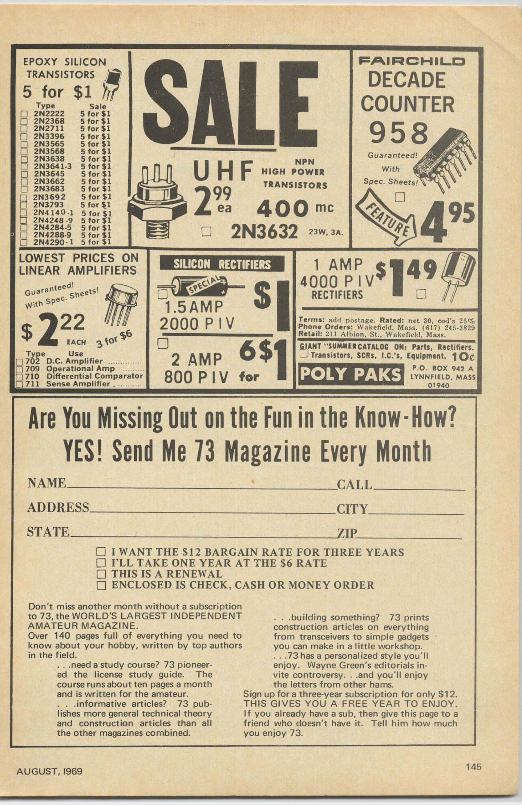
95
49o
With
Spec. Sheets!
F=AIRCHIL.C
DECADECOUNTER
958
1 AMP $4000PIV
RECTIFIERS
Terms: add postRll'e. Rated: net 30, cod 's 25%Phone Orders: W:l.kefil'ld, Mass. (617) 24 S-382!)Re t ol il : 211 Alb ion. S t. , Wakefield. Mass .
.GJ.ANT " SUMMU CATALOG ON: Parts, Rectifiers .
"
U..T,..ansistOtS, 5CHs, I.C,'" Equipment. 1 OeP.O. BOX 942 A
LYNNFiElD . MASS01940
s
for
6$
o299
ea 400 me
2N3632 23W,3A.
UHF HIGH P':;';IRTRANSISTORS
~.....1.5AMP
2000 P I Vo
2 AMP800 P IV
LOWEST PRICES ONLINEAR AMPLIFIERS
EPOXY SILICON
~R~~S:ST$~S ~Type S a le
o 2N2222 5 for $1o 2N2368 5 for $1
00 2N2711 5 for $1
2N3396 5 for $1
00 2N3565 5 for $1
2N3568 5 for $1
B 2N3638 5 for $12N3641·] 5 for $1o 2N3645 5 fo r $1o 2N3662 5 for $1o 2N3683 5 for $ 1
8 2N3692 5 for $ 12N3793 5 f or ~1
§ 2N4 14 0·1 5 for Sl2N4248 ·9 5 for S-l2N4284·5 5 for $1o 2N4288-9 5 tor 51o 2N4290 -1 5 f or $ 1
ed!Gl,.lara nte ~neet5!\Ni t tl Spec.
$ 2~A~ ~\o'~&Type U se
0 70 2 D.C. Amplifier ,0 709 Operational Amp .0 710 Differential Comparatorn 711 Sense Ampli fi er . " ,
Are You MissingOut on the Fun in the Know·How?YES! SendMe 73 Magazine Every Month
NAME ---'CALL _
ADDRESS, CITy _
STATE ---'ZIP:....- _
01 WANT THE $12 BARGAIN RATE FOR THREE YEARSo I' LL TAKE ONE YEAR AT THE $6 RATEo THIS IS A RENEWALo ENC LOSED IS CHECK, CASH OR MONEY ORDER
Don 't m iss anot her month without a subscriptionto 73, the WORL D'S LAR GEST I NDE PENDE NTA MAT EU R MAGAZ INE.Over 140 pages full of everyth ing you need toknow a bout your hobby , w ritten by top authorsin the field.
. . .need a st udy course? 73 p ioneered the license study guide. Thecourse runs about ten pages a monthand is written for t he amateur .. . .info rmative a rt icles? 73 publi shes more general technical theo ryand construction articles t ha n a llthe other magazines combined.
.. .building something? 73 printsconstruction articles on everythingfrom transceivers to simple gadgetsyou can make in a Iittle workshop.. . .73 has a personalized style you 'llenjoy. Wayne Green 's editorials invite controversy . . .and you 'll enjoythe let ters from other hams.
Sign up for a three-year subscription for only $1 2.THIS GIVES YOU A FREE YEAR TO ENJOY.If you already have a sub, then give this page to afriend who doesn't have it. Tell him how muchyou enjoy 73.
AUGUST, 1969 145
LIBERTYPAYS MORE! LIBERTY
OFFERS MORE!PRESTEL FIELD STRENGTH..METER
•••
•
WILL BUYFOR CASHALL TYPES
ELECTRON TUBESSEMICONDUCTORSMilitary Electronic
EquipmentTest Equipment
•\.
withunit.
s F
th is 4112There is
(Model 6T4GI
Freq uency Range : 40 to 230and 470 to 860 Megahertz.C a librated outward from 10to 50,000 Microvolts. Nothinqmakes it easier to prope rly andspeed ily find the correct placeto install TV, FM and Commun ica t ion A nte nnas. Yo u canmeasure and hear the signa ls
vo lt battery economically powerednothing else like itl
Only $120.00F.O.R. New York
WIRE. WRITE, PHONE COLLECT! WE PAY FREIGHT ON ALL PURCHASES WE MAKE
Liberty Electronics, Inc.548 Broadway, New York, New York 10012, Phone 212·925·6000
INDEX TO ADVERTISERS(continued from page 141)Dear Wayne,
Th is is the last straw- my mailbox couldn' t takeit! I am indebted to someone for sending me downa stash o f some 30 copies of 73 Magazine. Unfortunately they chose to arrive on Home Field Daywhen I had a sh ack full of ham s, so I had to waituntil those magazine-happy hams wen t home. Ihave since read them fro m cover-to-cover and allfull of interesting news and circuits. I want tothank you folks for sending them doc...-n to me.
Our interest in Project Oscar is taking a severeknockback, with no reliable informa tion av ai lableto us. 1have been runn ing our ZL-Oscar Net everyMonday evening for 104 week s now, and it suretakes some doing to hold a net toge ther for thatlong without any information to pass out. The boysin VK q uit answering mail about ten months back,and it was like finding gold in the streets to extractsome information on what was going on. From allaccounts things are at a real low ebb with Oscar. Ihave just received a letter from VK2APQ which indicates that yet another group is getting into theact and that Australis-A may yet be tossed aloft.Our shattered confidence makes us ultra-cautiousabout project "Mocnray ."
My 432 mhz converter is rough-looking. andevolved from that circuit yo u published . I had touse tubes in the osciUator chain. I have a homemade coaxial tank amplifier which I used on Oscars3 and 4. I had several reception reports from VKand ZL. but no two-way co ntacts. Those weregreat times and our group had a fine time chasingOscars .
Bruce Rawlings ZL lWBNew Zealand
146
ll, m." e u ' E I"" t . on ic S u p p 1v, 10 - 1 I.... m ... o Boo.., 371\ ",~.iean C ' V.,.I, 139.... "' ..lon.5 1.... n, ... n•• Inc. 57An'enna M ar< 9 1.... rch."... 89A.noI<H.69ATV.39
BC EI.."onic•. 1"39&F.1429;ye10... 14 1Bo'" Am.,,,,,., 9JBonanra.77e"ga•. 878u'llharo ' , 6 1
C.ll on y e lla . J9Cell 1>00• . 65 89CO R&d;o Co , 1J9CI...I."'; I n... 1 1 _ HI-19Columbia. 141CuShe.afl.55
D.h l. 140D .....son.99DCP.l00Do.. I<;ev. 53
fISCO.75[p.i1on,9 1E~.n'. 65
f AI R . 9 9F.eoc• • 9J
(,a l. x V, IIG~," E I""tron ie . , 1 1 IG.'.....V. 7 5G &G. 139Glob.I. 14 1C""d"UrI, 140G,u''''~', 119
H~Is"om, 4 ">....' ... 27H .....,y.33HCJ. 75H&L. 141H""'e<. A T 141
ICE. 36In , . , natio n al C' v ...,1 J
J."".. R .....,a'e". 9!.J a n C . vnal. 91)ef1 ," On in. 83
L""'"".ul 9 9Lib.... ' V . 14 6Lin.., Sv"-'" 7
M w.n . , 14 4M.so "" EI.. "onie., 1 36
..aho...., Ra<loo. 2 1" .... lronic., IV
P, ,on, . 71P~ , 8">P,~"."n~. I J 3Pol v P"", 14 5
Ou.•• e.,71Ou.n,e" '. I J J!>
R&dio Sh~<>. 7 IRedlin •. 4 1,124 13 7
Sale" 91S"o".._ G,,'d... 139S09n", 0 .... 0}
Soac•. 91S,.nley 106S ...... III
Tel •• , 47To...... , 93T ..o W.V, 9!>
U fO ....t 119Un a,hlla, 106Un ; ,oo Rad io , 9 1
Vanyu.'O. 4 ,,> , 4 1 , 61, {'9 11V •• jt.onie>, J IVH f.fo9Vib,opl • • 97
1"1"""", 1401"10,,<1 QSL 8u.uu. 25
13 Mag.,,,,.Boo'S. 120 121G lob.. , 8 1Sunoc,""';On>, 145G"nSlT'O•• 53Club h"<IIllle. 858.n<l ..... , 87
73 MAGAZINE
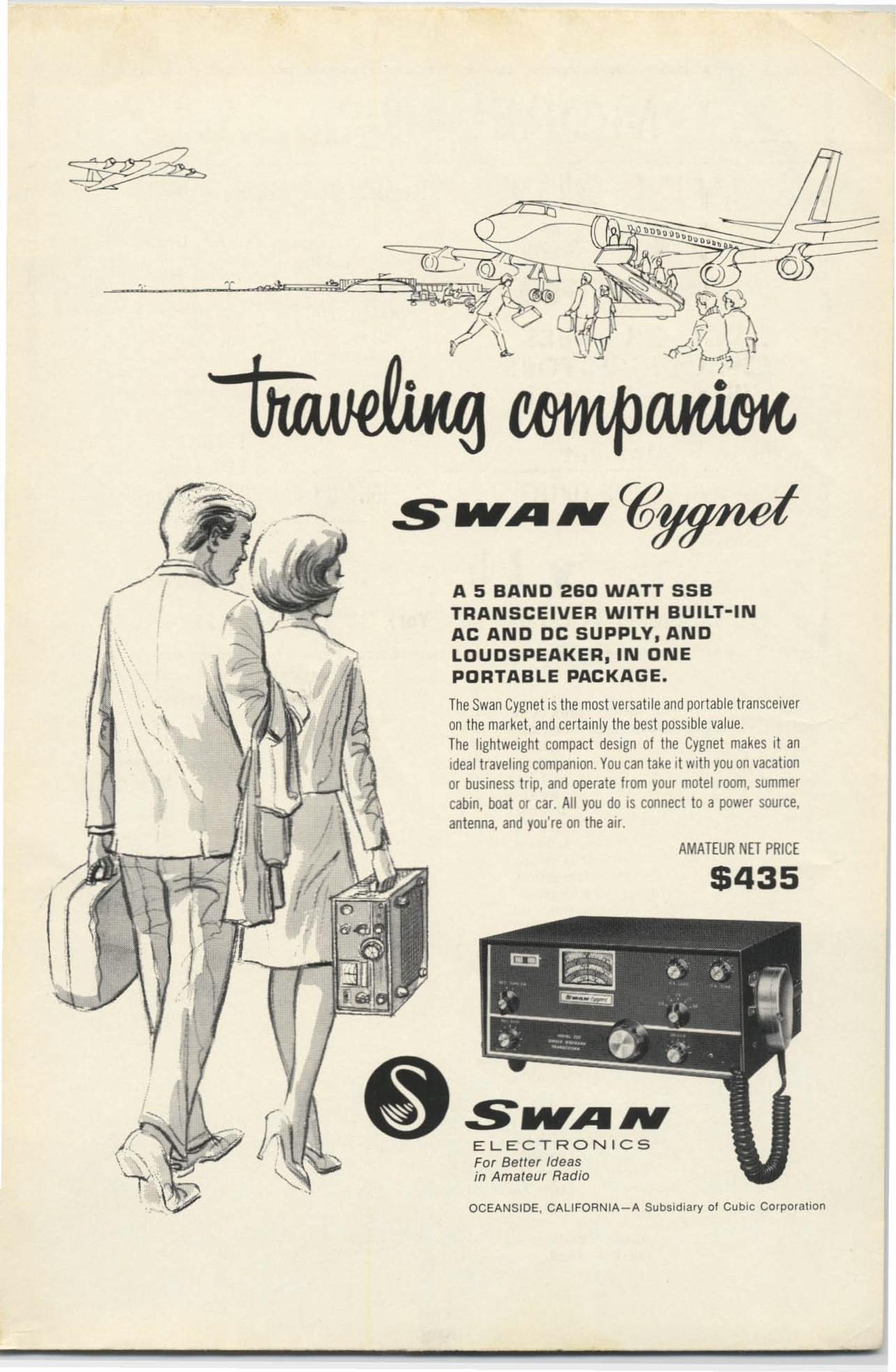
• •
-
ELE C TR ONI C SFor Better Ideasin Amateur Radio
OCEANSIDE, CALIFORNJA- A SUbsidiary of Cubic Cor poration
SMr'AIV
---....- ,
/ A 5 BAND 260 WATT SSB,TRANSCEIVER WITH BUILT-INAC AND DC SUPPLY, ANDLDUDSPEAKER, IN DNEPORTABLE PACKAGE•
•. , TheSwanCygnet is themost versat ileandportable transceiver, \ on the market. andcertainly thebest possiblevalue.,
\ ' The lightweight compact design of the Cygnet makes it an,
ideal travel ingcompanion. Youcan take it withyou on vacation
\
\, or business tnp. and operate from your motel room, summer
cabin, boat or car. All you do is connect to a power source,
, antenna, and you're on theair.
/AMATEUR NET PRICE
/' ; -/J 5435,,• ,
If£•
~ \
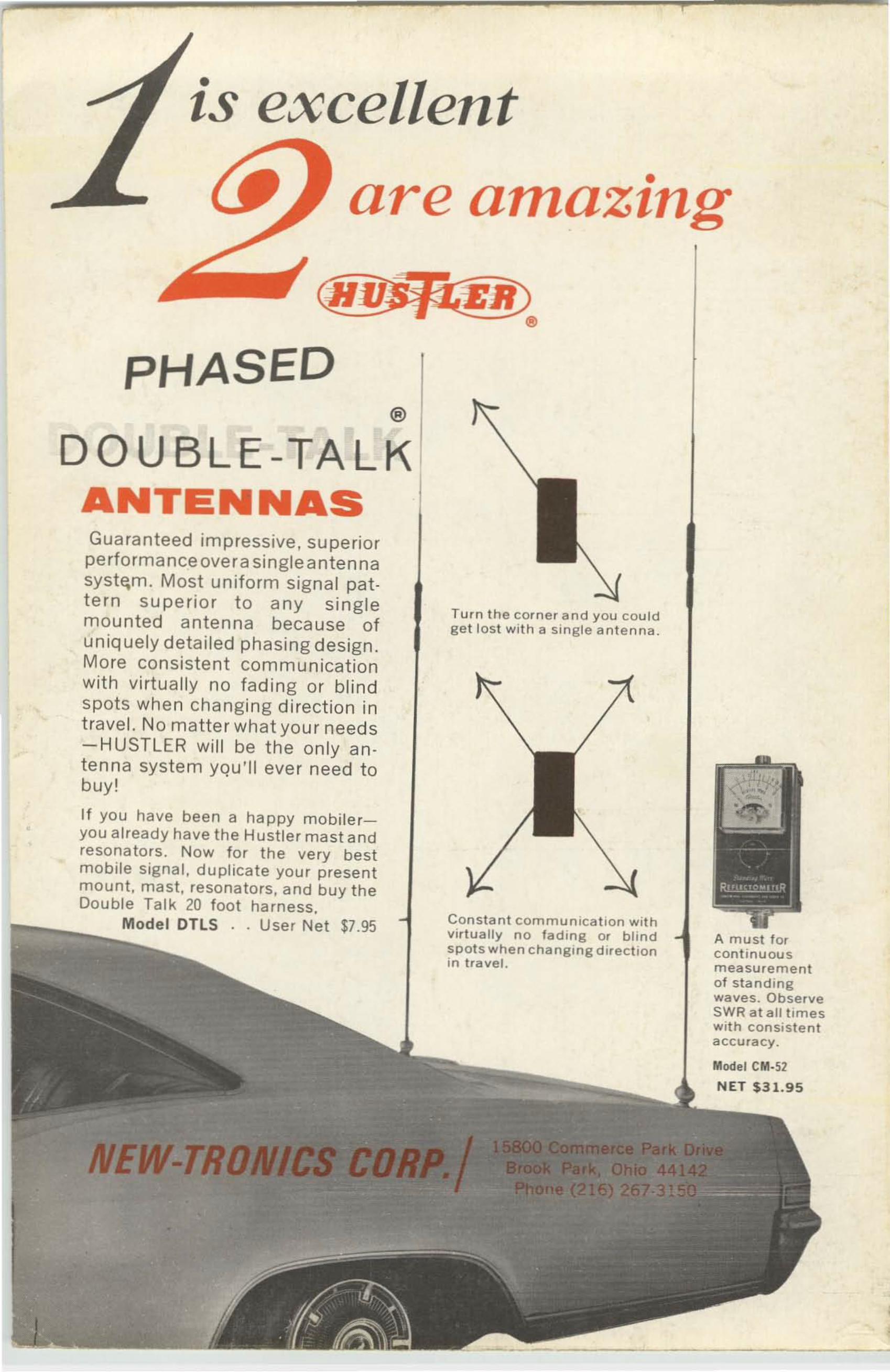
, ,
is excellent•are amazing
(jIJ/)fi;.'EB)4l>
PHASED
~------ -
A must forconti n uousmeasu remento f standingwaves. ObserveSWR at all timeswith consistentaccu racy.
Mode l eM.52
NET $31.95
Tu rn the corner and you couldget lost w it h a single antenna.
Constant communi ca t ion wIthvirtua lly no fading or blindspots whe n changmg directionin traver.
®
DOUBLE-TALKANTENNASGuaranteed impressive, su perio rperformance overa single antennasystem. Most uniform signal patt ern su pe rio r to any si nglemoun ted ante nna becau se ofun iquely detailed phasing design.More co nsistent co m m unicat ionwith virt ually no fad ing or blindspots when changing direction intravel. No matter what your needs-H USTLER will be th e on ly antenna system you'll ever need t obuy!
If you have been a happy m obileryou al ready have the Hust ler m a st andresonators. Now for th e very bestmobi le signa l, dupl ica te you r p resentmount, mast, resona to rs, and b uy theDouble Tal k 20 foot harness.
r:,",~:--~",:M:Ode ' DTLS . . User Net $7.95
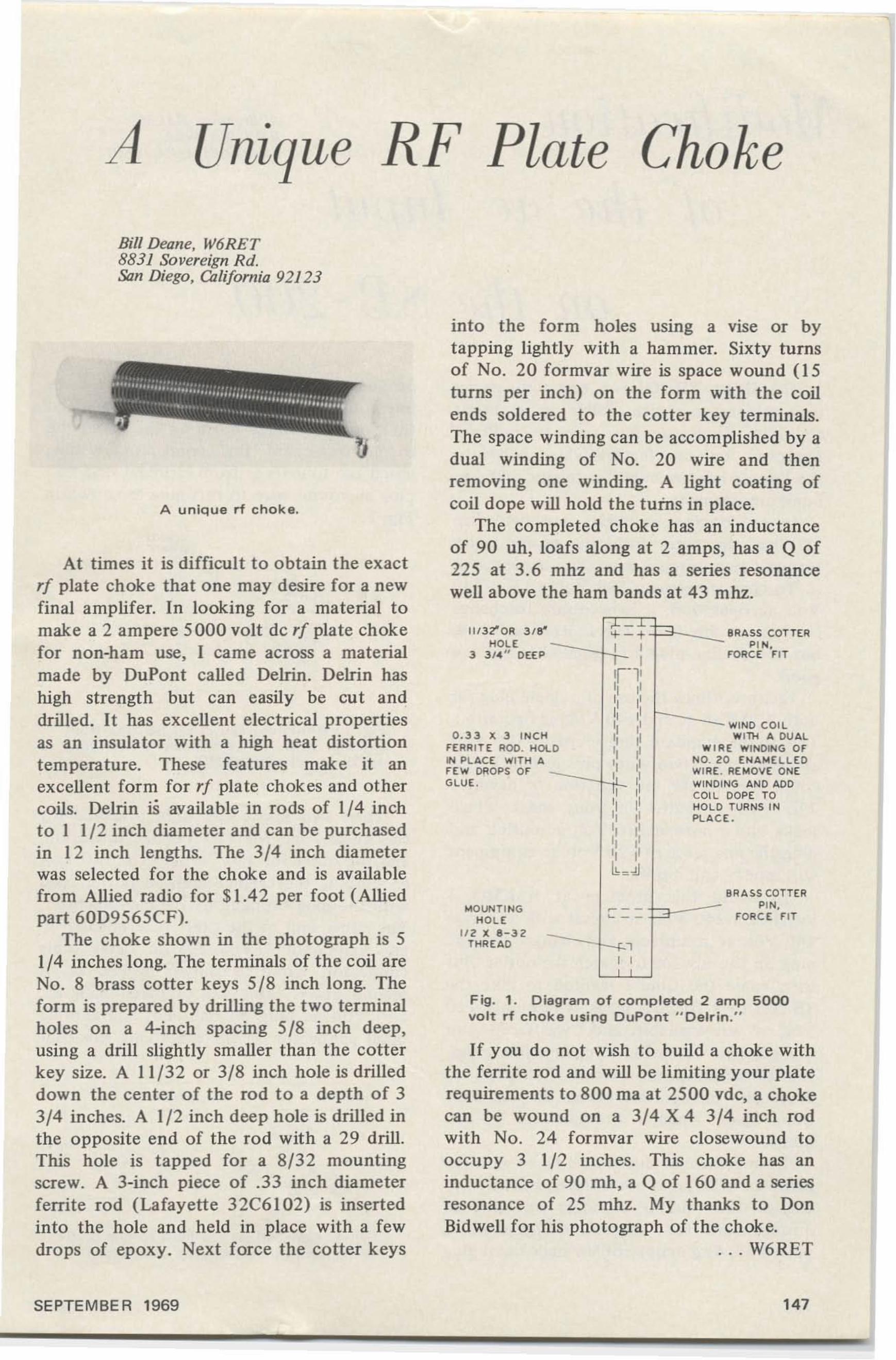
A Unique RF Plate Choke
Bill Deane, W6RET8831 Sovereign Rd.San Diego, California 92/ 23
A unique rf cho k e.
BRA SoSo COTTERPIN .
FORC E FIT
BRA SS COTTERPI N.
FORCE FI T
WIND COILWITH A DUAL
E WINDING OFo ENAM ElLE DREMOVE ONE
NG AN D ADODDPE TOTURNS I N
E.
¢: -~ .
I ,:,-1:II ItII IIII IIII II
0II II w'"II ,III II NO. Z
WIRE., " WIN Dt!I II COILII II HOLDII II PLACII I'II JIII II1h:41
~- -
" - -,
~ :
MOUNTI NGHOL E
li Z X 8 - 3 2THR EAD
11I3 2"'OR 3 / 8HOLE
3 3 1." DEEP
0 . 3 3 x 3 INC HFERR ITE ROO. HOI.IN PLACE WITH AFEW OROPS OFGLU E.
into the form holes usmg a vise or bytapping lightly with a hammer. Sixty turnsof No. 20 formvar wire is space wound (15turns per inch) on the form with the coilends soldered to the cotter key terminals.The space winding can be accomplished by adual winding of No. 20 wire and thenremoving one winding. A light coating ofcoil dope will hold the turns in place.
The completed choke has an inductanceof 90 uh, loafs along at 2 amps, has a Q of225 at 3.6 mhz and has a series resonancewell above the ham bands at 43 mhz.
Fig . 1. D iagram of completed 2 am p 5000volt rf choke using DuPont "Delrln. "
If you do not wish to build a choke withthe ferrite rod and will be limiting your platerequirements to 800 rna at 2500 vdc, a chokecan be wound on a 3/4 X 4 3/4 inch rodwith No. 24 formvar wire closewound tooccupy 3 1/2 inches. This choke has aninductance of 90 mh, a Q of 160 and a seriesresonance of 25 mhz. My thanks to DonBidwell for his photograph of the choke.
.. . W6RET
.. ,,', ..... ...!" .., ..·•·· ·•····..····'· ..'1"" · .... ..... ... .. ................ fill .." ..
At times it is difficult to obtain the exactrf plate choke that one may desire for a newfinal arnplifer. In looking for a material tomake a 2 ampere 5000 volt de rf plate chokefor non-ham use, I came across a materialmade by DuPont called DeIrin. Delrin hashigh strength but can easily be cut anddrilled. It has excellent electrical propertiesas an insulator with a high heat distortiontemperature. These features make it anexcellent form for rf plate chokes and othercoils. Delrin is available in rods of 1/4 inchto I 1/ 2 inch diameter and can be purchasedin 12 inch lengths. The 3/4 inch diameterwas selected for the choke and is availablefrom Allied radio for $ 1.4 2 per foot (Alliedpart 60D9565CF).
The choke shown in the photograph is 51/4 inches long. The terminals of the coil areNo. 8 brass cotter keys 5/8 inch long. Theform is prepared by drilling the two terminalholes on a 4-inch spacing 5/8 inch deep,using a drill slightly smaller than the cotterkey size. A 11/32 or 3/8 inch hole is drilleddown the center o f the rod to a depth of 33/4 inches. A 1/2 inch deep hole is drilled inthe opposite end of the rod with a 29 drill.This hole is tapped for a 8/32 mountingscrew. A 3-inch piece of .33 inch diameterferrite rod (Lafayette 32C6102) is insertedinto the hole and held in place with a fewdrops of epoxy. Next force the cotter keys
SEPTEMBE R 1969 147
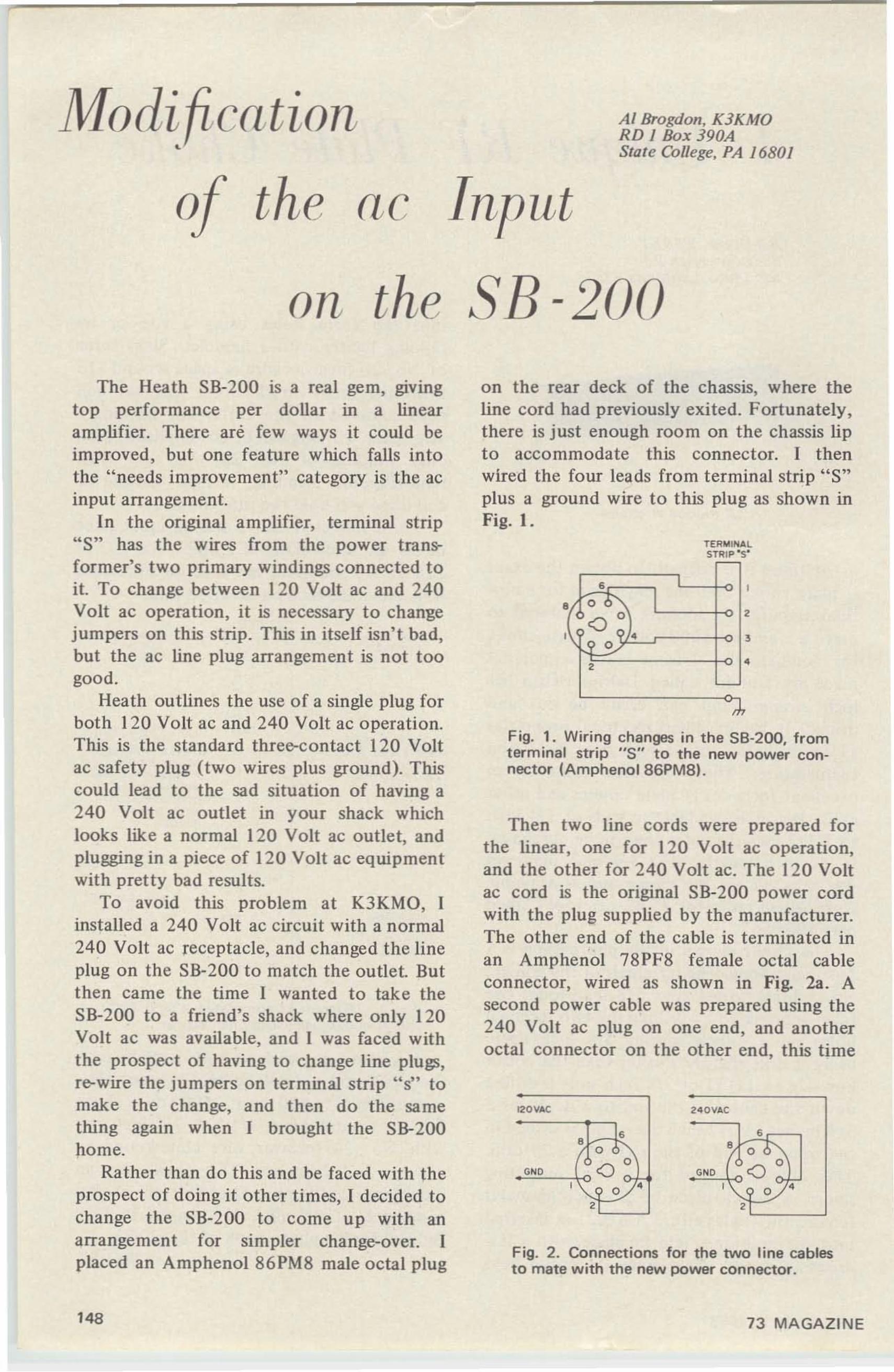
,
Modi fication•
o the ac Input
AI Brogdon, K3KMORD 1 Box 390AState College, PA 16801
on the SB-200
TERMI 'OALSTRI P -s-
Fig. 2. Connections for the two line cablesto mate with the new power connector.
Fig. 1. Wiring changes in the 56·200, fromterminal strip "5" to the new power connector (AmphenoI86PM8).
,
2 40YAC
s• 06"\
'" 00
''- 0/ 'a
o~,
• a0
0
,L9 0
,e
,
J,
IZOYAC
s• -,0
'" 00
''\ 0,
a
Then two line cords were prepared forthe linear, one for 120 Volt ac operation,and the other for 240 Volt ac. The 120 Voltac cord is the original SB-200 power cordwith the plug supplied by the manufacturer.The other end of the cable is terminated inan Arnphenol 78PF8 female octal cableconnector, wired as shown in Fig. 23. Asecond power cable was prepared using the240 Volt ac plug on one end, and anotheroctal connector on the other end, this time
on the rear deck of the chassis, where theline cord had previously exited. Fortunately,there is just enough room on the chassis lipto accommodate this connector. I thenwired the four leads from terminal strip "S"plus a ground wire to this plug as shown inFig. I.
The Heath SB-200 is a real gem, grvmgtop performance per dollar in a linearamplifier. There are few ways it could beimproved, but one feature which falls intothe "needs improvement" category is the acinput arrangement.
In the original amplifier, terminal strip"S" has the wires from the power transformer's two primary windings connected toit. To change between 120 Volt ac and 240Volt ac operation. it is necessary to changejumpers on this st rip. This in itself isn't bad,but the ac line plug arrangement is not toogood.
Heath outlines the use of a single plug forboth 120 Volt ac and 240 Volt ac operation.This is the standard three-contact 120 Voltac safety plug (two wires plus ground). Thiscould lead to the sad situation of having a240 Volt ac outlet in your shack whichlooks like a normal 120 Volt ac outlet, andplugging in a piece of 120 Volt ac equipmentwith pretty bad results.
To avoid this problem at K3KMO, Iinstalled a 240 Volt ac circuit with a normal240 Volt ac receptacle, and changed the lineplug on the SB-200 to match the outlet. Butthen came the lime I wanted to take theSB-200 to a friend's shack where only 120Volt ac was available, and I was faced withthe prospect of having to change line plugs,re-wire the jumpers on terminal strip " SH tomake the change. and then do the samething again when I brought the SB-200home.
Rather than do this and be faced with theprospect of doing it other times, I decided tochange the SB-200 to come up with anarrangement for simpler change-over. Iplaced an Amphenol 86 PM8 male octal plug
148 73 MAGAZINE
F F Fsales to licensed Amateurs only
A ll equipmen t is guaran teed to be exactly asadvertised. We have a very large stock ofequipmen t, ho wever, no ca talogs or lis t areavailable. Tell us what you are looking for,we may have it. WE WILLNOT BE
WE WILL NOT BE UNOERSOLO.25% deposit required on all c.o.d . orders.Prices subject to change without notice.
MOTOROLA60 WATT
FOURCHANNEL
150MCMOBILES
Motorola X53-GJ V. 6/12 volts-1 50mhz- 60Watts. These un its are exceptiona ll y clean andin mint condit io n. They are complete wi th fourfreq. cont ro l head, cables. m icrophone. speaker.Less ovens & ant . Transmitter is narrow band.receiver is wide band. Special, only $ 175. 00 ea.
Motorola 150mc hand i-talkies model H23-1.These are like brand new and co mplete, lessbattervs and ant . on ly $49.95 ea.
Mo toro la transistorized paging receiver, 150mcH0 3anc-excellent ccnd., less battery. $ 34.95ea.
M AofOTO~Ol.""
MOTOROLAHandi-Talkia
150 mc . 5w, 2 f req .co m p lete w it h
nicadsan d ante nna
ModelP33-A M-1131 AMexcel lent condo
$98.00 ea.
4~R 48/u:DELIVERY
OROER DIRECTwith check or money order to
Spec ia l Quan tity Pr icesto Jobbers and D ealer s
T RENTON. M ICH IGAN 48183
2400B Cr)'1tal Dr., Ft. Myerl, Fla. 1!l901CRYSTALS
We have in stock over six million crystalswhic h include types C RI AIAR, Ff243,Ff24l , MC? , Ff249, HC6/U , HCl 3/ U,etc_ Send 10¢ fo r our 1970 catalog withoscillator circuits, listing thousands o f frequencies in stock for immediate delivery.(Add 1O¢ per crystal to above prices forshipment 1st class mail : 15¢ each for airrnail.)
r--"'-!.."fiEED CRYSTALS?
SPECIALSColor TV crystal (3578, 545KHz) wire leads 51 .60 4 for 55.00100KHz frequency standard crystal (HC13/U) 4.501000 KHz frequency standard (HC6/U) 3.50Any CB crystal transmit or receive 2.25Any amateur band crystal (except 80 meters) 1.50 4 lor 55.00Any marine frequency (HC6/U) 2.8580 meter cyrstals in FT243 holders 2.50
hou r s: by appoin tment only19675 A L L EN ROA D PHONE : 3 13-282-64 64
wired as shown in ig. 2b. Notice that withboth power cables, the ac input is connectedto the proper transformer leads, and theappropriate jumper connections are alsomade in the octal connector.
Therefore, the change from one inputvoltage to the other req uires only that theappropriate ac input cable be connected.Caution: Be sure all jumpers are removedfrom terminal strip "S" when this modification is made.
If you are building an SB-200 from thekit, this cha nge can be incorpora ted as theamplifier is being built , eliminating terminalstrip "S" completely. The transformer primary leads and capacitors C I and C2 can bewired directly to the octal plug. Be carefulnot to cut the transformer primary leads offtoo short by following the instructions fornormal wiring. Just wait and cut them tolength when you're ready to connect them.
This same approach can be used with anypiece of eq uipment which has provisions foreither 120 Volt ac or 240 Volt ac line input.And other types of connectors can be usedaccording to your personal preference.
. _. K3KMO
SEPTE MBE R 1969 149
LETTERS
Dear Wayne,There were several omissions in 'the schematics
of the "Six Meter KW Linear" in the July issue.The most important are as follows :
Page 2 1. 1. Coil data not given- should be3 or 4 turns of 1/8" copper tubing, 1" diameter,spaced to resonate wi th the chosen capacitor.
2. There should be a connector in series wi thone lead of Kl - this goes to the N. O. contacts ofthe exciter PIT relay .
3. R2 is lOOK, » walt.4. Cathode pins 2 and 4 should be grounded
in addition to pins 6 and 8.Page 23. 1. Note 4 should read transient rather
than equalizing.Many thanks for the new tower and antennas.
the cassette tape recorder, the trip through theHeath factory, and the other things 73 has boughtfor me in the year I have been sending in fillers.They are very much appreciated. I hope I will beable to supply similar material for "73 Junior."
Would 73 be inte rested in a short ar ticle on thesubject of how semiconductor grade silicon is produced?
Bill TurnerFive Chestnut Court
Saint Peters, Missouri 63376No . . .ed.
Dear Sir :We thought it may be of interest that there is a
new net on the air for emergencies and OX contacts. The world OX Round Table operating on14270 KC Wednesday and Saturday from 05000800 GMT.
All QSL's fo r ne t contacts may be forwardedto (WA5UllR) net QSL manager.
Scott Freile1510 Lynnview
Houston. Texas 77055
Dear OM Wayne,I was gi ven "Dx-Handbook" first-edition fro m
my good friend WA9NKG, "Paul ' & find it a verynice book, especiall y I enjoyed the article about80 meters OX. Here in JA, there are not so manyOX's on 80 meters, only JA6AK is ac tive. Hi.By the way I found some misunderstanding onpage 90, "Call Areas." Please correct as follows:
JAPAN Wrong RightJAI Kanto, Shinetsu JA I Kan toJA2 Tokai , Hokuriku JA2 TokaiJA9 Fukui, Toyama,
Kanazawa, Ishikawa JA9 HokurikuJ A0 Nagano, Suwa,
Niigata JA0 ShinetsuJ A9 includes three prefectures; Fukui, Toyama,& Ishikawa, and Kanazawa is capital ci ty of Ishikawa, like Phoen ix in Ariz! JA0 has two prefec tures; Nagano & Niigata, and Suwa is the name ofone city in Nagano!
About 7 or 9 years ago in JA, there were only
150
S areas from JA I to JAS,and then J A I & JA2 weredivided into two till then JA I had Kanto & Shinetsu, JA2 had Tokai & Hokuriku, bu t since thenShinetsu changed to JA0 & Hokuriku ~ot J A9calls, so you might use the old da te ! Hi. Anyway now you are all right!
Another info here. you wrote " for OX Watchfor gigantic do-it-yourself coloring map," on 22page. We can buy do-it-yourself map for OX fromour JA RL. About 55x80 em ¥ 200 (about 60()with great circle map. This map is very nice forOX hound! You may get the map if you sendabou t $1 to JARL, P. O. Box 377, Tokyo.
Oh, one more info , JAI area go t too manyh ams and they needed another call so they usedJHI. It was two or three years ago. And nowJHl also going away the newest call righ t now(29 June '69) is JHI VZZ and JH1 Y .. . JHI Z. .. is used for club stations so the rest is JHI WAAto JHIXZZ, when all of these calls u sed, they useJR 1. First JRl will go on the air in '69!
Narumi Kawai. JA9APS1-10 Suwanokawara
Toyama-City 183. Japan
Dear Wayne.I read with interest the article on facsimile and
the radio amateur by Ralph Steinburg K6GKX inJune, 1969_ (I also had an article starting on page130.)
You should know th at facsimile and slow scanTV are exactly the same thing elect ric ally if youadd a horizontal sync pu lse to the facsimile signal.
1 have been running slow scan TV for the past2%. years (one and a half years under the specialslow scan TV license), using facsimile equipment.As far as I know, th is is completely legal since Iam conforming in every way to th e various television kinds of signals th at are being sent. Thosewho are receiving the slow scan TV signal usingfacsimile equipment can use the horizontal syncpulse if they wish. Those receiving the slow scanrc signals on a CRT presentation, generally requirethe sync pu lse. Those that are receiving them onfacsimile machines , do not need it.
Mr. Steinburg's statement, "with slow scan television legal on the low bands, facsimile may be thenext mode of communica tions to follow in thenear future. All it needs at the present time isenough interest by the radio amateu rs to show theFederal Communicat ions Commission, by petition,that facsimile will contribute to the state-of-theart," really impedes matters by conti nuing the flcti on that there is a difference be tween facsimileand slow scan TV.
J. R. Pcpkin-Clurman, W2BK1623 Straight Path
Wyandanch, New York 11798
73 MAGAZINE
R. E. G .._~..• _ ..... INC.Box 1220·GC. Beverly Hills, Calif . 90213
Phones : Area 213 Office -272-5707Messages-275-5342
FAIRCHILD SOLlD·STATE SCOPES all w /dual ·t race plu g-ins 25 & 50 m h z. w/delayed ttme-beseplug -ins. w/boo ks, over ha u led & grtd. As lawas 825.00
We proba bl y have the best invent o ry of good la btest equipme nt in t he co u nt ry , But. please do n o task for c a ta log I A s k for spec if ic items o r kinds ofitems y o u n eedl We a lso b uyl What do you h ave?
•
Dear Wayne.Thanks for the articles by Kl YSD. Many moons
have passed since I laughed so hard. As a resultof your fine articles on the Advanced Class LicenseI passed my test.
AE u i.. AND. LM , ETC.PP· 10 6 /U: Metered . Knob 'adjustable 90 ·270 v u pto 8 0 m a ere : also select a n AC of 6 .3 v SA, or 12 .6v 2% A o r 28 v 2% A . With mating o ut pu t p lu g &a ll [ech oda[a . S hpg wt 50~ 19.50BARGAINS WHICH THE ABOVE WILL POWER 'LM ·(-l Freq . Meter : . 12 5 ·20 mhz• .01 %, CW o rAM , with seetet.me tcneo ca lib . bo o k . [ec h o cere.mating plug . Checked & grtd 5 7 .50TS·323 Freq . Met ... : Sim ila r to above but 2 0- 480m hz.. 001 % . Wit h data 169 .50T S-175 Freq . Meter : 85·1000 mhz 75.00A.R .C . R 11 A : Modern C ·5 ·er 19 0 ·55 0 khz 12.95A.R .C. R22: 540·1600 khz w/t un ing grap h 17.95A .R .C. R 13B : 108·132 mhz w/tun ing grap h.2 7.50
HI·SENSIT IV ITY UHF RECEIVER375-1000 mttz , Stoddart AF I Mete r N M -5 0Awith pwr. sply . co rd s. dipole holder. 3 pa ir di·poles. I nput 50 o hms. IF 6 0 m hz . Band width I mhz at 370 and 1.8 at I ghz A F . I mage& spurious-response reject . better than 40 db .Sen sit . as a 2 -termina l tuned vo ltmet e r is 10 uv:w ill be less with t-patr dipole . but y o u c a n mak ea n a rra y to b ring it up . If the vo lt age-atte n u a tion cettb . c harts didn't get lo st it would beworth $1,250 in surp lus. $2.852 from t hef actory . . ... so we w ill se ll it as a si mp le re ceive r in grtd -excel. condition fo r on ly ... $275
ULTRA-WIDE-BAND RECEIVER :AN/A LR·5 : Lat e postwar AM/FM Countermeasuresrcvr. Has S·Mete-T; variable- IF All en . & passban d (0.2 or2 mhz from 30 mhz ce-n t e-r ) ; AF. Video & Pan. out puts.New, modified for 120 v 60 hz, includes new (Method IIpack ) 4-ban d plug-in converter .038· 1 ghz. 4 Type-Nplugs automatically select correct ant . as bands are switched . Sensu . at -6 db setting : 6lh uv thru 132 mhz, 13thru 780 mhz & 4 5lh at 1 ghz . BRAND NEW, with book& mating pwr·inp ut plug, only 275 .00
VERSATILE PLAT E & FILAM. TRANSFO R ME RDepot Spares fo r SP-600·JX: P ri . 9 5 / 105/ 1 1 7/ 13 01190/2 1012341260 v S O/60 hz . Sec. 1 : 30 S ·0-3 0 5v , 150 ma o Sec. 2 : S v 3 A . Sec . 3 : 6 .3 v SA .Sec . 4 : 7 Yo v , 3/4 A . Sec . 5 : 7 Yo v . 1 11. A . L89.e [lgfor pins is plainly marked . Herm. sea led 2.95
FOUNOI A NEAT & COMPA CT SCOP'E XFRMR!Freed 12 6 91 : DAS Loran S pa res. supplied S" CR,p la t es & htrs. Pri. 105 · 130v 50/60 hz . Sec's. insu l.S k v : 14 9 0 & 1 100 v , 5 ma ; 3 9 0 ·0·390 v 100 rna :electrD.sta .t ically -~hielded 6 .3 v, 0 .8 A : ew e 2% .v.l. ,2A . Sec s. Insul. 1 :'-; kv : two 6 .3 v , 6 A . 5 v , 3 A, ..:: ~
v . 5 A . Case 5 Y.x5x7 '4 . With diagram. ShippedI b co llec t R EA Express 2 .95
Tom Shirley. K4HVV410 Patton Road
Hinesville. GA 31313
Herbert S . Dunkerley. WA3JI XRFO 2
Jean n ette. P A 15644
Dear Editor.Would any members of the American Cryp
togram Association who are readers of "73" dropa line to the writer? The intent is to form a netto discuss cryp to systems and solutions.
Thank you .
Dear Wayne.Up until the past few months. very little effort
had been made to attract youngsters into our ranksand it is indeed regretful that we have been so t ardy in promoting amateur radio to this particular agegroup. Ed itorials in some of the amateur magazineshave at last recognized the severe lack of youthintake in amateur radio and soberly suggest that wemake strong efforts to try and introduce theseyou ng people to ham radio.
Some may ask. " Why is youth so important toamateur radio?"
There are a multitude of good reasons why amateur radio needs new blood and certainly each reason has its own meri ts. To mention but two. wemight start with what amateur radio as a hobby canprovide for a youngster just getting started in hamradio . It offers a youngster the chance to converthis spare ti me from roaming the streets, lying idleon the couch, etc., to something cons truct ive, educating, challenging and rewarding. For some, amateur radio can lead to a very successful career inelectronics later in life. Amateur radio in the yearsto come, will need new amateurs to improve thesta te of the art and in general to man the helm. Todays you thful prospective amateurs will be the people to assume thi s task. This is why it is of cardinalimportance that all amateurs do their utmost tofamiliarize the yo uth of today with ham radio.
Today's youth are basically a good group ofpeople and they have a tremendous amount of potential and ene rgy which if could be di rected to thearea of amateur radio, would lead t o an eventuallicense and a genuine feeling of accomplishmentand satisfactio n.
Boy Scout Explorer posts. high school radioclubs, camps and other outlets have time after t imegraduated the prospective young amateur fromtraining in code and theory , to an amateur license.However, the se organizations lack the abili ty tomake the initial contact with a youngste r and this iswhere the individu al amateur must help out.
One may ask at this point, "Well, what can Id ?"o .
Get in touch with the youngs te r down the streetand invite him or her over to the shack. Fire up therig ana ex plain how it works. Show th em your collection of qsl's-Iet them have a try at the mikeshow them what an amateur license looks like- bepatient and encourage them, and mos t of all, letthem know that you sincerely want to help them.You might then direct them to a local radio club orsome other group that teaches code and t heoryclasses fo r future hams. If there isn't any suchgroup in the area, then you, yourself. could certainly help these young people. Five wpm and elementary theory and regulatory material cer tainly isn'tdifficult to teach to eager students, is it? They willalways admire you for your guidance and assistance.believe me.
While amateur equipment becomes more andmore sophisticated, and with DXpeditions and contests taking up a substantial amount of our hammingtime amongst other facets of amateur radio, let usnot neglect the youth around us for they certainlyhold a share in ham radio's future.
The initiative is up to you. Ham radio is a veryfascinating and rewarding hobby and has so verymuch to offer. Why not get in touch with theyoungster down the road and lend the helping handthey need and at the same time. strike a blow foramateur radio.
Ralph J. lrece, Jr•• WA 1GE K
SEPTEMBER 1969 151
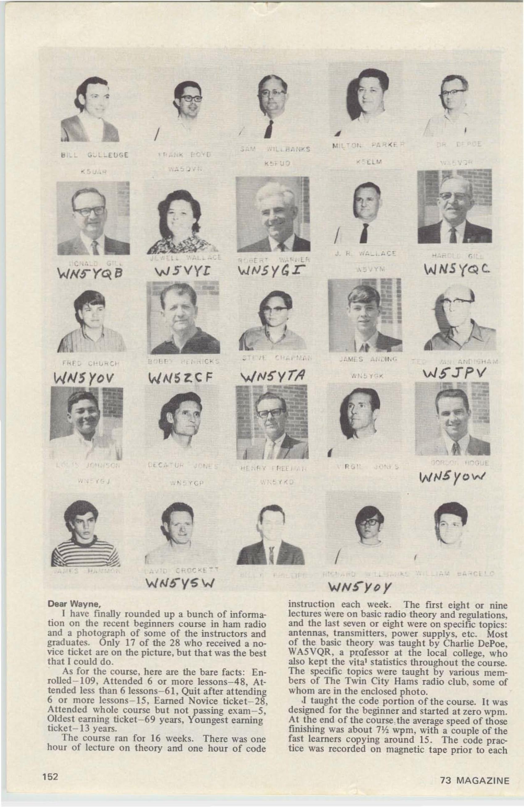
•
,
wtJSyow
~ Ll-II
. . ,..-' ''_0. ''.-
r. . 0( t
,', t . ~ f . "
• •. M, ~ .... 11 . '
I I
I
•, .' ,
I •
., .
,
•
,.
,
[ " ' . l '
wtJsyGr
l
(<.:. ,-•
• •
,
I ! C ..
/
WSVYI
,,
WN'5ZCF
. ,.
WNSyoV
r I I
Dear Wayne.I have finally ro unded up 3 bunch of inforrna
tion on the recent beginners course in ham radioand a photograph of some of the instructors andgraduates. Only 17 of the 28 who received a novice ticket are on the picture, but that was the bestthat I could do.
As for the course, here are the bare facts: Enrolled -109. Attended 6 or more lessons-48, Attended less than 6 lessons-61 , Quit after attending6 or more lessons- IS, Earned Novice ticket- 2B,Attended whole course but not passing exam- S,Oldes t earning ticket-69 years. Youngest eamingticket- 13 years.
The course ran for 16 weeks. There was onehour of lecture on theory and one hour of code
instruction each week. The first eight or ninelectures were on basic radio theory and regulations,and the last seven or eight were on specific topics:antennas, transmitters, power supplys, e tc. Mostof the basic theory was taught by Charlie Devoe,WASVQR , a professor at the local college, whoalso kept the vital statist ics throughout the cou rse.The specific topics were taught by various members of The Twin City Hams radio dub, some ofwhom are in the enclosed photo.
.1 taught the code portion of the course. It wasdesigned for the beginner and started at zero wpm.At the end of the course.the average speed of thosefinishing was about 7~ wpm, with a couple of thefast learners copying around 15. The code praclice was recorded on magnetic tape prior to each
152 73 MAGAZINE
•FAIRCHILD/DUMONT TC-175Best Grade Solid State TV Cameras-700 line Resolution-l0 ft. Candle Sensitivity. Excellent.like new condition. Complete with Vidicon & schematic. Both Video & rf output. Regular$1200.00 Net-our SPECIAL $449.95 less lens.Ask for our new free listings 869M1 & 969J2-full of incredible bargains. Flyer 96981 out
September 10th. THE DENSON ELECTRONICS CORP.Post Office Box 85 (203) 875-5198 Rockville, Connecticut 06066
Recent FCC NewsRM-886. The ARRL has requested that theCW-only band on two meters be moved fromthe high end of the band to the low end,144.0 - 144.1 mhz. It has been the customto use only CW in this lower 100 khz of theband, however, it may be worthwhile tomake this into law if there are too manyoperators that refuse to honor the convention. It seems a shame that we have to makefederal laws just to force a few inconsiderateoperators to conform to custom.
RM-950. The ARRL has requested the opening of 28.0 - 28.5 mhz for F 1 emission.This is RTTY which is now restricted to theCW portions of 8G-4G-2G-I 5 meters. Itshould have been allocated that way in thefirst place. It is nice to see the ARRL behindthis request ... they were the principleopposers to the original requests for FI onthe low bands and managed to delay theFCC ruling on this for several years.
RM-981. A petition has been filed with theFCC to open all bands from two through 80meters to maritime mobile while in Region 2and to open 3.5 - 3.8 and 7.0 - 7.1 mhz formaritime outside of Region 2. At presentmaritime ops are permitted to use 40 thru 2meters in Region 2 and 2G-I 5-1 0 metersoutside Region 2. Seems reasonable enough.
RENEWAL CODE
The two numbers under your call on the ad.dress label are the expiration code. We havetried to m<!lle it simple. The first number is themonth th<!lt we send you the l<!Ist copy on yoursubscription and the second number is the yeM.78 would be July 19b8. for example.
Now BIGGER andBETTER Than Ever!
----MAIL THIS COUPON NOW---I
• NAME ; ._ __ _._._ II ADDRESS ' _ II CiTY : STATE: ZIP: " IL lFor yo..r FIfE copy. fill Ollt CO.pOIl oft4 moll. D.,at. 7)
BRI ARELECTRONICS
10 ALICE ST. BINGHAMPTON, N.Y.
13904, AC 607 723-3111
• COPPER CLAD PC BOARDS, 6" X 36"CC both sides $2.16, 6" X 9 3/4" CCboth sides 60i, 7" X 11 3/4" Coneside 84i, 5" X 7v," CC both sides 40i,
• STUD MT SILICON RECTIFIERS 12amp, 50 PRV. pkg of 5 $1.00
• ELECTROLYTICCAPACITOR 1250 mfd180 vdc. 2" X 4%" 50i ea.
• JUST BOUGHT OUT ORIGINAL CASEFOR CB RADIO. Includes mtg bracketfor mobile use & slide-in chassis. Holespre-punched for power transistor & pow'er cord. May be used for mobile powersupplies, P.A. system or speaker box ormany other uses. Size' 3v," H X 7" WX 8Y." D. Weight 3 Ibs. Original cost$9.95. Our price $1.95
MIN ORDER $5.00
SEPTEMBE R 1969 153
GATEWAYELECTRONICS
6150 Delmar Blvd.. St. Louis, Mo. 63112314·726·6116
Meters-Wide-Vue Illuminated (new) 4"x3" typesavailable: VU Meter, 1 rna meter, So.o-SO Microamp meter.
Nlil~P~U~E~' 1 Ibt ype'NL-8037i5031 $ o~e9~n~~diameter tube 0.6 inch numeral numbers 0thru 9.
5c~r~gbl1r6d2:1gpE' TUBE ' $ 6.50 ea.Shipping wt. 1 lb $ 5.00
ELECTRICAL KEY SWITCH OPDT for burglaralarms or equipment protection complete withkey.Shipping wt. 1 lb $ 1.25
HP-212 Pulse Generator excellent condoShipping WI. 50 Ibs $195.00
AUTOMATIC ICE CUBE MAKER Fits most re-frigerators and freezers new with diagram andinstructions for installation .Shipping wt. 12 Ibs $ 9 .50
12 VOLT CENTER TAPPED TRANSFORMER Pri.115 volts 60 cycles-Sec. 12 volt center tapped@70 amps.Shipping wt. 35 Ibs. . . . . . . . . . . . . .. $ 9.95
12 VOLT D. C. TO 115 VOLT A. C. TRANSIS·TORIZED INVERTER KIT-200 watt output com~Iete with all parts, case and diagram.
hipping wt. 25 lbs. . . . . . . . . . . . . .. $ 18.956 VOLT D. C. RELAY 5 amp contacts DPOT:
Shipping wt. %Ib $ 1.50Minimum order $5.00. Sorry, no catalog at thistime. Write for specific items. Watch for ourads in 73. Stop in and see us when you're in St.Louis.
HAMS! DON'T BUY USED TUBESCOMPARE OUR PRICES
FOR NEW TUBESRCA-GE-EIMAC-AMPEREX-ETC.
811 A-4.75. 4-125A-27.50. 4-65A-12.00.5R4GY-l .75. 807-1.75. WE35018071-1.25.4-400A-38.50, 813-20.95, 4X150A-19.95,4-250A-36.50, 4PR60B-55.00, 4CX250B-21.00.8236-12.95. 2E26-2.75. 16251807-12v fiI)-1.10,417A-2.25, 404A-2.25. 6146-2.75. 63603.00. 2X2- .50. OD3-0C3- .75, 5879-1.75.5881 -3.25. WE-CV677 1000WATT TETRO DE5.95. EIMAC-MACHLETT VT-158 1200-3000WATT BOTTLE-READ MARCH 1969 ISSUE 73HOW GREAT THIS IS-9.95! 12V 20AMP DIODEPOWER SUPPLY ILESS XFORMERI -4.95. RCA6-12 VDC CONVE RTER DEL. 20AMP-12.95IDEAL FOR VOLKSWAGEN. SENO FOR OURLIST OF OVER 3000 TYPES OF AMERICAN.BRITISH AND EUROPEAN IMPORTED TUBES.LARGEST STOCK OF XMITTING TUBES INTHE WORtD. SEND FOR OUR LARGE PARTSCATALOG (OUR PRICES ARE THE LOWEST INTHE USA).
UNITED RADIO COMPANY56·A FERRY STREET
NEWARK, NEW JERSEY 07105
154
session to keep sending errors and resulting confusion to a minimum.
Everyone in the club agrees that the course wasan unqualified success and that we all learned agreat deal from it. It is still hard to believe thatso many people are interested in amateur radio andare just looking for a chance to get into it. Anyclub can do itself a lot of good by encouragingpeople with a genuine interest.
Now, can anyone tell me how to keep 28 brandnew Novices on the air?
Bill Gulledge. K5UAR700A Plum Street
Monroe. LA 71201
Dear Wayne.Since working as Chief Engineer of KALX (FM),
my perspective on the Amateur license technicalexamination has changed. Many people will agreethat it is a simple and uncomplicated task to passthe technical section. But in comparison with theFirst Phone exam, it is hardly a test at all.
You might note that the Amateur license is justthat: for amateurs. But what has this done to thequality of the average 'ham? One can simply listento the low bands any evening to provide the answer.
The degradation in quality has been broughtabout through the lack of respect in the ham license. Years ago it took real perseverance andintelligence to be a ham operator. There were noreadily available stations, as today. Kits, if any,were almost the same as building from scratch.And when the ham was finished with a piece ofgear, a receiver perhaps, he had a sense of pride,a sense of accomplishment. Today, the closestthing to that most hams experience is the sense ofrelief one feels when the last payment is made ona complete transceiver. Too, there was a feelingof fraternity. There was belonging, brought aboutbecause there was a great hurdle that everyonr hadto pass to become a ham: the building ofa transmitter and receiver, and the exam.
Today the exam is not difficult. And todaythe only comradeship most hams feel is in theirmutual animosity towards CB'ers. Little wonder 'that the bands should be in such poor shape. Whenone loses respect in something, one is not apt totake good care of it.
One good way to make an Amateur licensemore valued is to require a stiff technical exam,one that would require actual studying, not memorization sessions with the License Manual. Butthe more difficult technical skills it engenderswould prove greatly beneficial to the ham, and thecountry. It might even save the Amateur RadioService.
I'd like to hear your comments on my letter.Stephen L. Diamond, Radio KALX
500 Eshleman HallBerkeley. California 94720
73 BINDERS
Are your magazines fallinq down all the time?Our bright red binders will hold them on thebookshelf. Stamped in gold. Specify year. Only~3 each, but going \.Ip before long. Order.
73 PETERBOROUGH NH 034SB
73 MAGAZINE
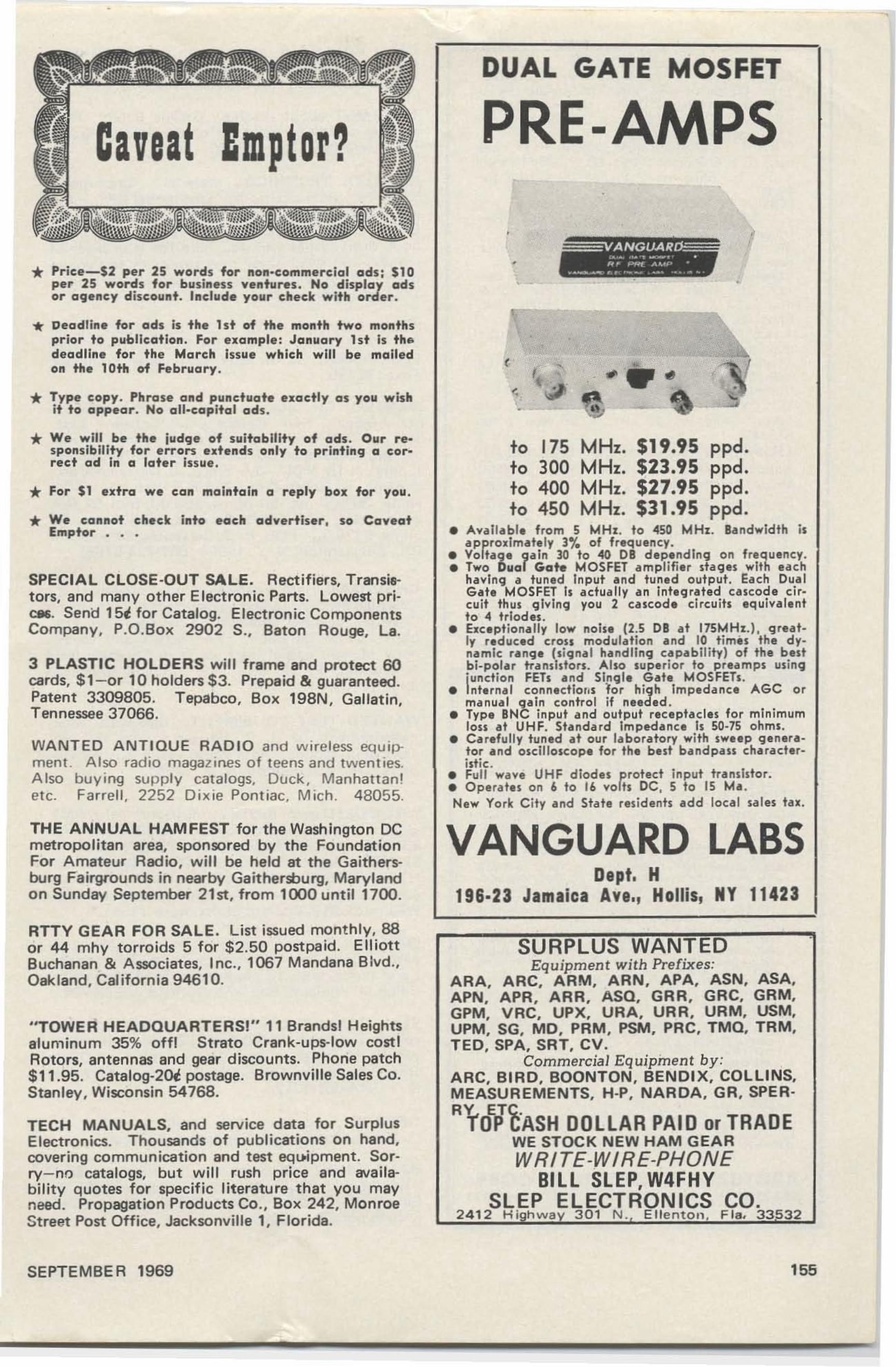
DUAL GATE MOSFET
PRE-AMPS
* Price-$2 per 2S words for non·commerclal ads; $10per 25 words for business 'futures. No display adsor agency discount. Include your check with order•
•ANGVAll..--... -., .
,,~ _ AOM" •w__ ..... __ • __• • _~ .
•
I
... Deadline for ads Js the lst of the month two monthsprior to publication. For exomple: January lst Is thedeadline for the March Issue which will be mailedon the 10th of February.
* Type copy. Phrase Gnd p"nduate eKoetly as you wishit to appear. No oil-capital ads.
.. ...* We will be the judge of suitability of ods. Our s-e
sponslblllty for errors eltends only to printing a correct ad In a late .. Issue,
* For $1 extra we con maintain a reply box for you .
* We cannot check into each advertiser, so CoyeatEmptor • . •
SPECIAL CLOSE·OUT SALE. Rectifiers, Transistors, and many other Electronic Parts. Lowest prlC86. Send lSi for Catalog. Electronic ComponentsCompany, P.O.Box 2902 5 ., Baton Rouge, La.
3 PLASTIC HOLDERS will frame and protect 60cards, $l-or 10 holders $3. Prepaid & guaranteed.Patent 3309805. Tepabco, Box 198N, Gallatin,Tennessee 37066.
WANTED ANTIQUE RADIO and w ire less equipment. Also radio magazines of teens and twent ies.A lso buying supply catalogs, Duck , Manha ttan!etc. Farrell , 2252 Dix ie Pontiac. Mich . 480 55.
THE ANNUAL HAM FEST for the Washington DCmetropolitan area, sponsored by the FoundationFor Amateur Radio, will be held at the Gaithers-burg Fairgrounds in nearby Gaithersburg, Marylandon Sunday September ztsr, from 1000 until 1700.
RTTY GEAR FOR SALE. List issued monthly, 88or 44 mhy torroids 5 for $2.50 postpaid. ElliottBuchanan & Associates, lnc., 1067 Mandana Blvd.,Oakland, California 94610.
''TOWER HEADQUARTERSI" 11 Brandsl Heightsaluminum 35% offl Strate Crank-ups-low cost IRotors, antennas and gear discounts. Phone patch$11.95. Catalog·20i postage. Brownville Sales Co.Stanley, Wisconsin 54768.
TECH MANUALS, and service data for SurplusElectronics. Thousands of publications on hand,covering communication and test equipment. Scrry-nn catalogs, but will rush price and evallability quotes for specific literature that you mayneed. Propagation Products Co., Box 242, MonroeStreet Post Office, Jacksonville 1, Florida.
SEPTEMBE R 1969
to 175 MHz. $19.95 ppd.to 300 MHz. $23.95 ppd.to 400 MHz. $27.95 ppd.to 450 MHz. $31.95 ppd.
• A...al labl. from 5 MHz. to 450 MHz. Bandwidth is"r.rodmat.ly 3% of fr.quency.
• Vo t.9. 9aln 30 to 40 DB dep.ndlng on fr.quency.• Two Dual Gate MOSFET .mplifi.r stages with each
h....lng a tuned Input and tun.d output. Each DualG.te MOSFEl Is actually an Integrated ceseode elrcuit thus gl ... lng you 2 cesccde circuits equi.... I.ntto 4 triodes .
• bc.ption.lly low noise (2.5 DB .t 175MH:r..1. great·Iy r.duced cross modulation and 10 t im.s the dy.namlc r.ng. (signal h.ndllng capabi lity) of the bestbi-polar transistors. Also sup.rior to preamps usin9',unction FEls and Sing I. Gat. MOSFETs.
• nt.rn.l ccenectlcns lor high Impedan,. AGC ormanual qaln control if needed .
• Typ. BNC input and output r.ceptacles for minimumIon at UHF. St.ndard Impedan,. Is 50·75 ohms.
• Car.fully tun.d at our laboratory with swup genera·tor and esetneseeee for the b.st bandpass charact.r·btte .
• Full wa...e UHF diodes r.roted input tr.nslstor.• Ope rat.s on I> to 16 "'0 ts DC, 5 to 15 Ma.New York City and State residents add loca l sales tax.
VANGUARD LABSDept. H
196.23 Jamaica Ave., Hollis, NY 11423
SURPLUS WANTEDEquipment with Prefixes:
ARA. ARC. ARM. ARN. APA. ASN. ASA.APN. APR. ARR. ASQ. GRR. GRC. GRM.GPM. VRC. UPX. URA. URR. URM. USM.UPM. SG. MD. PRM. PSM. PRC. TMQ. TRM.TED. SPA. SRT. CV.
Commercial Equipment by:ARC. BIRD. BOONTON. BENDIX. COLLINS.MEASUREMENTS. H·P. NARDA. GR. SPERo
RrolThsH DOLLAR PAID or TRADEWE STOCK NEW HAM GEARWRITE-WIRE-PHONE
BILL SLEP, W4FHYSLEP ELECTRONICS CO.
2412 Hi h w a 301 N . Ellenton , Fla. 33532
155
Ii •
SURPLUS PARTSLatching Betev . Potter & Brumfield KB. 3POT .115 v. 60 st art, 6 v 60 stop. The 2 relays can beseparated, mak ing a OPOT re lay w ith 115 v ,co il , & a SPOT with 6 v. coi l. 5 amp contact s .51.25 each, 6 tor $6.00.POWER TRANSFORMER. 275 v. no ct. 150ma., 12v.@2 amps. 115v. 60 pr i. 2 3/4" >t 4"x 3'/., .. h . Shpg. wt . 7 Ibs. $ 1.75 each. 4 for$6.00.POWER TRA NS., 350-0-350 v , @ 130 ma.. 6.3v , @ 3.6 A ., 5 v, @ 3 A . 11 5/230 v. ps- i. Openframe w ith leads, Shpg. wt . 7 lbs. $2.00..5 mf 400 v , oil-filled capacit ors, rectangularcase , mil. spec. $ 1.00 per dozen .Loading capac itor , s-secncns, 400 pf . per section , 3/B" shaft . Will load ful l p ower in to 50ohms. $2.00 each . A dapter t o Y." shaft . 2st.Shpg. wt . 4 Ibs.f -inch PM speakers. 5 .4 ohms. A lso makegood m ike. A mer ican made. 75t each.Transistors: 2N 1187, 2N 1311, 2N586_ 15«each , 25 tor $2.50.Command XMT R SPECIAL: BC·457, 4·5.3Mc.. good for vto or fo r parts. Fair condo Lesstubes. Shpg. wt. 13 lbs. $3.00 each, 6 for$15.00.GUARANTEED USED HAM GEARNational NC-303 with cal ibrator. Mint . $200.00Mosley CM· 1 rece iver $ 80. 00Surplus BC·348 w ith AC power . $ 70.00pala>ty V with AC supply . $300.00Heath OX· 1oo Xm t r , $ 75 .00Globe Hybander V HF·62 Xmt r. S 49 .00Hammarlu nd HQ·140X recewee S100.00Hammarlund HQ·145X receiver w/spk t $ 160.00
..JEFF-TRONICS4252 Pearl Rd. Clvlnd ,O . 44109 749-4237
1 700 transistor t y p e s at 3ge each.40 watt ger manium powe r tra nslsto rl same as Delco
501 2N278 Iet c.l , Cat: 349 , 5ge each.C olor T V ca rt r id ge f o cus rect if ier 6 .5 kv. Used in
avary colo r T V . Cat: CF R·20, 7ge each.Motorola 2500 mao at 1000 p iv, h i$lh voltage/cu r
rent epOoty si licon rect if ia r . a>tlal lea d s. Cat:HEP · 170 , 4 ge each .
2 Pri nted circui t I.F . transformersJ.~ lug, 4 5 5 kc In-p ut a n d o u tpu t, Ca t : 19\r.:1P4, 9ge each .
R CA UHF t rans Istor type T V tuners, KRK ·120(lan a -shaft). Cat: U HF ·20, KR K·120 {sh o rtsh a ft l . Cat: UHF ·2 1. each $4.98 ,
RCA V HF tra nsinor t y p e T V tuners, K RK ·14 6 ,Cat: V H F -74 . $9 .99 e ac h .
Transistorized UHF tuners used in 1965 to 19 67T V SlIts made by Admira l. RC A . Motoro la, etc .Removable geanng may va ry fro m o n e make toa nother . Need o n ly 12 volt s DC to fu nction.No fil ament voltage needed. E asy reotecemeotunits. Cat : U H F -56 7 , $4 .95 .
UH F T u ner o rl \il ln a l un its a s used in TV sets suc h asRCA . Adm Ira l, e t c '
icover ing c ha n n e ls 14 thru
82 , a s part n o . 940 73 ·2. Complete with tube.O n ve gearing is removable. Can be used in mostSlItS. Cat: U H F -3 , $ 4. 95 . •
Colo r yokes. 70 degrees fo r all a rou nd colo r C R T's.Cat : X RC 70, $ 12.95. 9 0 degree. for all rectan gular 19 t o 2 S " c o lor C R T 's, C at : X RC ·9 0,$1 2.95 .
K it o f 3 0 t este d germanium diod e s. C at; 100. 9ge.Si licon rect if ier~ o c tal ba sed r~ lacement for 5 AS 4
5AW4 ·5U 4 ·oY3 ·5 T 4 -5V4·5Z4 . Wit h dia gra m .Cat: Rect · l 9ge lNICh .
7 " , 9 0 degrees 'Tv bench ten pictu r. tu be w it h ad·apte r. No ion t rap needed . C at : 78P7.$7 .99 .
T u be certons 6 A U 6 et c. , slz ei
$ 2 .1 5 p e r 100.6SN7 etc., size $ 2 .55 p e r 00. S U4GB sIze$2.95 p er 100, 5 U4 G sIze 4e eecn .
S e nd for comp lete f ree catalo~. Inclu d e 4 % o f dol la r valu e o f o rd e r f o r postage. $ 5 MI NIMUMO R D E R. Canad ia n c heck , 8 % d o llar d iffe re nt ia l.
ARCTURUS .ELECTRONICS CORP.502·22..d St. , U.IOfl Cit,. N.J. 07017 De,t.M13'''CHI.: 201·UN 4·55'.
156
OHIO VALLEY 6 meter phone net 50.350 everySunday. 2000 EDT. WA8WIW, NCS Scio toville,Ohio. Traffic and Rag Chewers Welcome.
FIND OUT about the New Greene Balun. Readall the details on page 59 of thi s issue. GreeneBalun, Warfield, R.1. 02880
WANTED : TECHNICAL material. Corp modelXFK freq . shift exciter for Tmc model GPT 750also TMC single sideband exciter. model SBE forGPT 750 & manuals-plus 18 to 30 foot parabo l ic dish . What w ill you take for it in place ofmoney-will swap brand new towers or test equipment. Write. wire or call : Eugene Leger. HollisSt.• East Pepperell . Mass. 01437 .
SELL: COLLINS KWS·1, Ser. 896. $640; 75A4,Ser. 5763. $420-or both for $1025. I w i ll ship.Lew Hindert, Rt . 4. Box 290. New Braunfels.Texas 781 30.
WANTED: CR tube for Tektronix 561 or 561Aoscilloscope. Sell : Collins CC-2 Carrying Case.$50.00; TMC Commercial TIG-1 two-tone oscillator . $95.00; Kepco SC·18-4M transistori zed powersupply. 0-18 VDC. 0-4 amps. 0 .1 % regulation.metered. $ 110 .00; Bird 6254 R·F watt meter. 0-2watts. 30-500 me, 50 ohms, $50.00; Bird 67 R·Fwatt meter. 0-25/100/500 watts, 30·500 me. 50ohms. $1 25 .00. FOB. H. T. Cervantes. 34 JohnsonRd., Binghamton, N. Y . 13905 (607·724·57851.
CHRISTIAN Ham Fellowship now organized forChristian fellowship and gospel tract efforts amongChristian licensed amateurs. Christian Ham Call book. $1 .00 donation . For details and samplecopy of ham gospel tract . write to Christian HamFellowship. P. O. Bo x 2 18. Holland. Michigan49423.
WANTED TEST EOUIPMENT: Bird watt meter,measurements of G. R. sig. gen. up to 450 mc;Tektroni x scope. State price. W2E DN . 93 Gilmore Ave.• Binghamton, N. Y. 13901.
WR L'S USED gear has trial-terms-guarantee! KWM 1-$249.95; HW32-$89.95; Swan 250-$249.95; TR3$369.95; NCX 3-$169.95; SB34-$299 .9 5; Galaxv V·$229.95; Galaxv Vmk2-$279.95 ; Ranger-$99.95;HT32A-$259.95 ; 100V-$259_95; Galaxy 2000 linear-$329.95. Many more. Free " blue-book " list.WRL. Box 919, Council Bluffs. Iowa 51501.
WANTED: Turret Turner w ith coils or old chassisw ith Turner for Hammarlund SP400X receiver.Later model w ith 13 plate stator & 14 plate rotor.Ralph M. Williams. Box 372. Dixfield. ME 04224.
SELL HALLICRAFTERS HT·32 Transmitter, excellent condition inside & out, $210. Will deliverwithin 50 miles. Want Collins 32S1 or 3283.Robert Kujawsk i. WA2VD X. 30 Rose St.• Florida,N. Y. 914-651·72h.
GREENE .. center dipole insulator with .. or.. without balun . . see September 73 issue.
HAMS WHO LIKE audio. too. try new quarterly:A mpl if iers by Williamson and Bailey. speaker byBaxandall. Details. Audion 307 Dickinson Ave.•Swart hmore. PA 19081 .
73 MAGAZINE
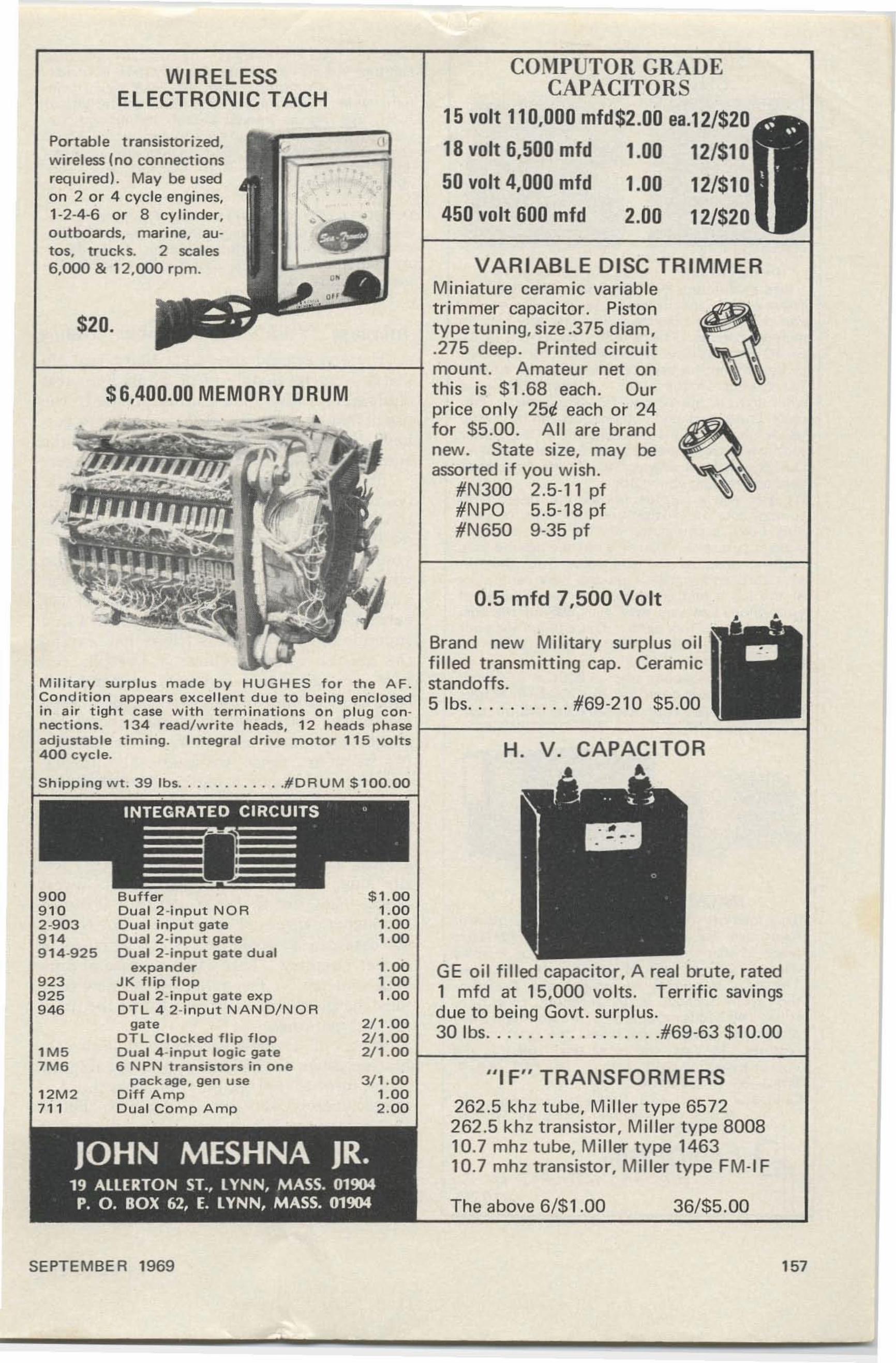
36/$5.00
H. V. CAPACITORA
0.5 mfd 7,500 Volt
The above 6/$1.00
"IF" TRANSFORMERS262 .5 kh z tube, Miller type 6572262.5 khz transistor, Miller type 800810.7 mhz tube, Miller type 146310.7 mhz transistor, Miller type FM-I F
COI\IPUTOR GRADECAPACITORS
15 volt 110,000 mfd$2.00 ea.12/$20
18 volt 6,500 mfd 1.00 12/$10
50 volt 4,000 mfd 1.00 12/$10
450 volt 600 mfd 2.00 12/$20
GE oi l filled capaci to r, A real brute. rated1 mfd at 15.000 vo lts . Terrific savingsdue to being Govt. surplus.30 Ibs #69-63 $10.00
Brand new Mili ta ry surplus o ilfi lled t ransmitt ing cap. Ceram icstandoffs .5 Ibs #69·210 $5.00
WIRELESSELECTRONIC TACH
$6,400.00 MEMORY ORUM
$20.
JOHN MESHNA JR.19 ALLERTON ST., lYNN, MASS. 01904
P. O. BOX 62, E. lYNN, MASS. 01904
Portable t ransistorized. (Iwireless (no connectionsrequired ), May be usedon 2 or 4 cycle engines.1-2-4-6 or 8 cy li nder, ..o utboards. marine. autos, trucks. 2 scales6.000 & 12.000 rpm.
Mil itary su rp lus made by HUGHES fo r the AF .Co ndit io n appea rs excellent d ue to b e in g e n cl o sedi n ai r t ight case with t erm inat io ns o n p l ug c o n n ect ions. 134 rea d/ wr it e heads, 1 2 heads phase I--- ------------ ----jadjustab le timi ng . Int egra l drive motor 11 5 volts4 0 0 cycle.
Shipping wt. 39 Ib s #DRUM $ 100.0 0
9 00 Buffe r $ 1 .0 09 ' 0 Dua l 2 -i npu t N OR 1.002-903 Dual input gate 1 .009 '4 Dual 2 -input gate 1.009 14-925 Dual 2 -input gate dual
expander 1.00923 J K f lip f lo p 1.00925 Dual 2 -input gate exp 1.009 46 D T L 4 2 -in p u t NAN D/NO R
gate 2/ 1.00DTL Clocked flip fl o p 2/1. 0 0
l M5 Dual 4 -input logic gate 2/1 .007M6 6 NPN transistors in one
package, gen use 3/ 1.0012M 2 Diff Amp 1.00711 Dual Comp Amp 2 .0 0
VARIABLE DISC TRIMMERMiniat ure ceramic variabletrimmer capaci to r. Pistontype tuning. size .375 d iam,.275 deep. Printed circu it
I-------------------t mount . Amateur net o nthis is $ 1.68 each . Ourprice o nly 25(/ each o r 24for $5.00. All are bra ndnew. State size. may beassorted if you wish.
#N300 2 .5-11 pf# NPO 5.5-18pf#N 650 9·35 pf
SEPTEMBER 1969 157
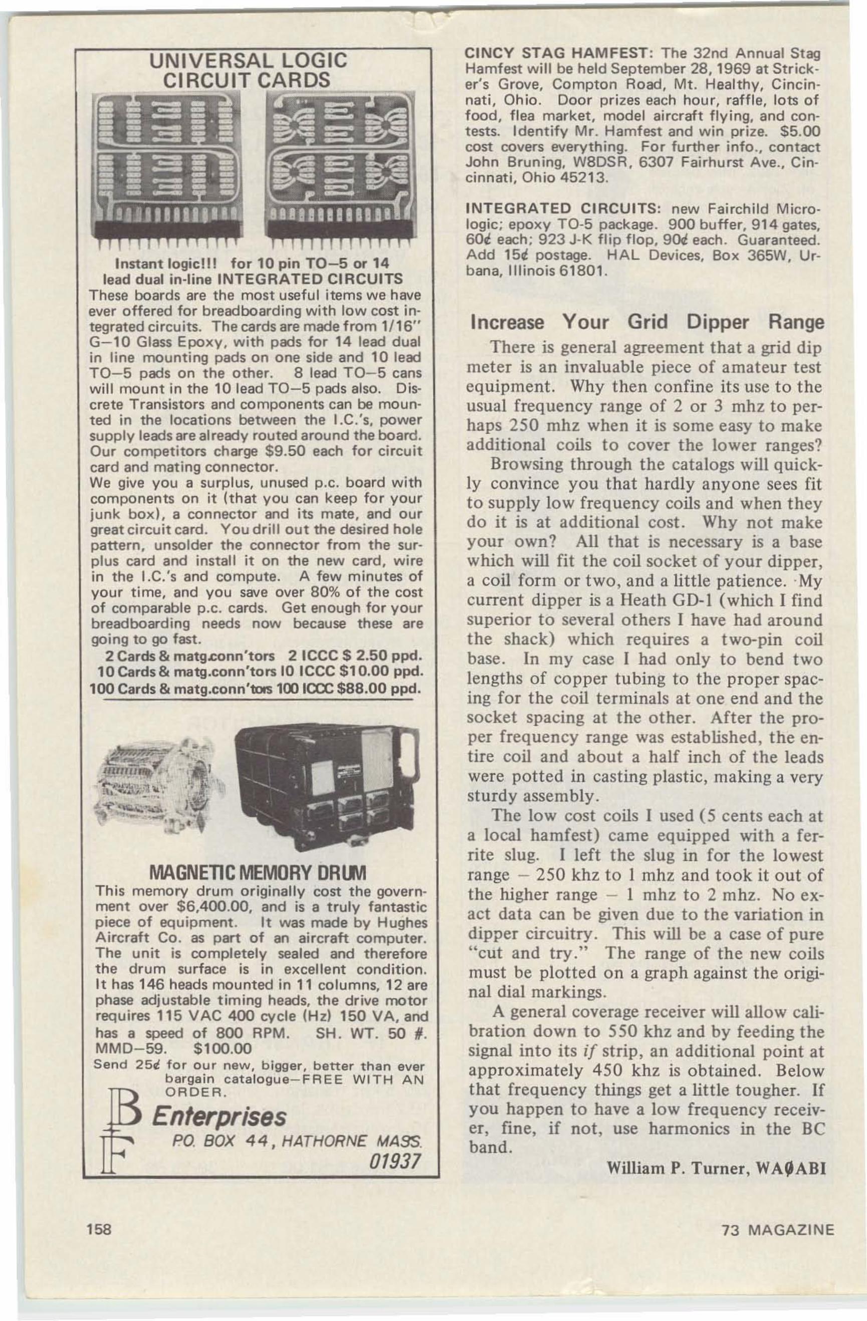
UNIVERSAL LOGICCIRCUIT CARDS ==
Instant logiclll for 10 pin TO-5 or 14lead dual In-line INTEGRATED CIRCUITS
These boards are the most useful items we haveever offered for breadboarding with low cost integrated circuits. The cards are made from 1/16"G-l0 Glass Epoxy. with pads for 14 lead dualin line mounting pads on one side and 10 leadTO-S pads on the other. 8 lead TO-5 canswill mount in the 10 lead TO-S pads also. Discrete Transistors and components can be mounted in the locations between the l.Cc's, powersupply leads are already routed around the board.Our competitors charge $9.50 each for circuitcard and mating connector.We give you a surplus. unused p.c. board withcomponents on it (that you can keep for yourjunk box). a connector and its mate, and ourgreat circuit card. You drill out the desired holepattern, unsolder the connector from the surplus card and install it on the new card, wirein the I.C.'s and compute. A few minutes ofyour time, and you save over 80% of the costof comparable p.c . cards. Get enough for yourbreadboarding needs now because these aregoing to go fast.
2 Cards & matg.conn'tors 2 ICCC $ 2.50 ppd.10 Cards & matg.conn'tors 10 ICCC $10.00 ppd.
roo Cards & matg.conn'tots 100 ICCC $88.00 ppd.
MAGNETIC MEMORY ORLMThis memory drum originally cost the government over $6,400.00, and is a truly fantasticpiece of equipment. It was made by HughesAircraft Co. as part of an aircraft computer.The unit is completely sealed and thereforethe drum surface is in excellent condition.It has 146 heads mounted in 11 columns, 12 arephase adjustable timing heads, the drive motorrequires 115 VAC 400 evcle (Hz) 150 VA, andhas a speed of 800 RPM. SH. WT. 50 I .MMD-59. $100.00Send 25t for our new, bigger, better than ever
bargain catalogue-FREE WITH ANORDER.
EnterprisesPO BOX 44, HATHORNE MASS.
01937
158
CINCY STAG HAM FEST: The 32nd Annual StagHamfest will be held September 28, 1969 at Stricker's Grove, Compton Road, Mt. Healthy, Cincinnati, Ohio. Door prizes each hour, raffle, lots offood , flea market, model aircraft flying, and contests. Identify Mr. Hamfest and win prize. $5.00cost covers everything. For further info ., contactJohn Bruning, W8DSR, 6307 Fairhurst Ave ., Cincinnati, Ohio 45213.
INTEGRATED CIRCUITS: new Fairchild Micrologic; epoxy TO-5 package. 900 buffer, 914 gates,GOi each; 923 J-K flip flop, 901i each. Guaranteed.Add lSi postage. HAL Devices, Box 365W, Urbana, Illinois 61801 .
Increase Your Grid Dipper RangeThere is general agreement that a grid dip
meter is an invaluable piece of amateur testequipment. Why then confine its use to theusual frequency range of 2 or 3 mhz to perhaps 250 mhz when it is some easy to makeadditional coils to cover the lower ranges?
Browsing through the catalogs will quickly convince you that hardly anyone sees fitto supply low frequency coils and when theydo it is at additional cost. Why not makeyour own? All that is necessary is a basewhich will fit the coil socket of your dipper,a coil form or two , and a little patience. .Mycurrent dipper is a Heath GD-l (which I findsuperior to several others I have had aroundthe shack) which requires a two-pin coilbase. In my case I had only to bend twolengths of copper tubing to the proper spacing for the coil terminals at one end and thesocket spacing at the other. After the proper frequency range was established, the entire coil and about a half inch of the leadswere potted in casting plastic, making a verysturdy assembly .
The low cost coils I used (5 cents each ata local hamfest) came equipped with a ferrite slug. I left the slug in for the lowestrange - 250 khz to I mhz and took it out ofthe higher range - I mhz to 2 mhz. No exact data can be given due to the variation indipper circuitry. This will be a case of pure"cut and try." The range of the new coilsmust be plotted on a graph against the original dial markings .
A general coverage receiver will allow calibration down to 550 khz and by feeding thesignal into its if strip, an additional point atapproximately 450 khz is obtained. Belowthat frequency things get a little tougher. Ifyou happen to have a low frequency receiver, fine, if not, use harmonics in the Beband.
William P. Turner, WA~ABI
73 MAGAZINE
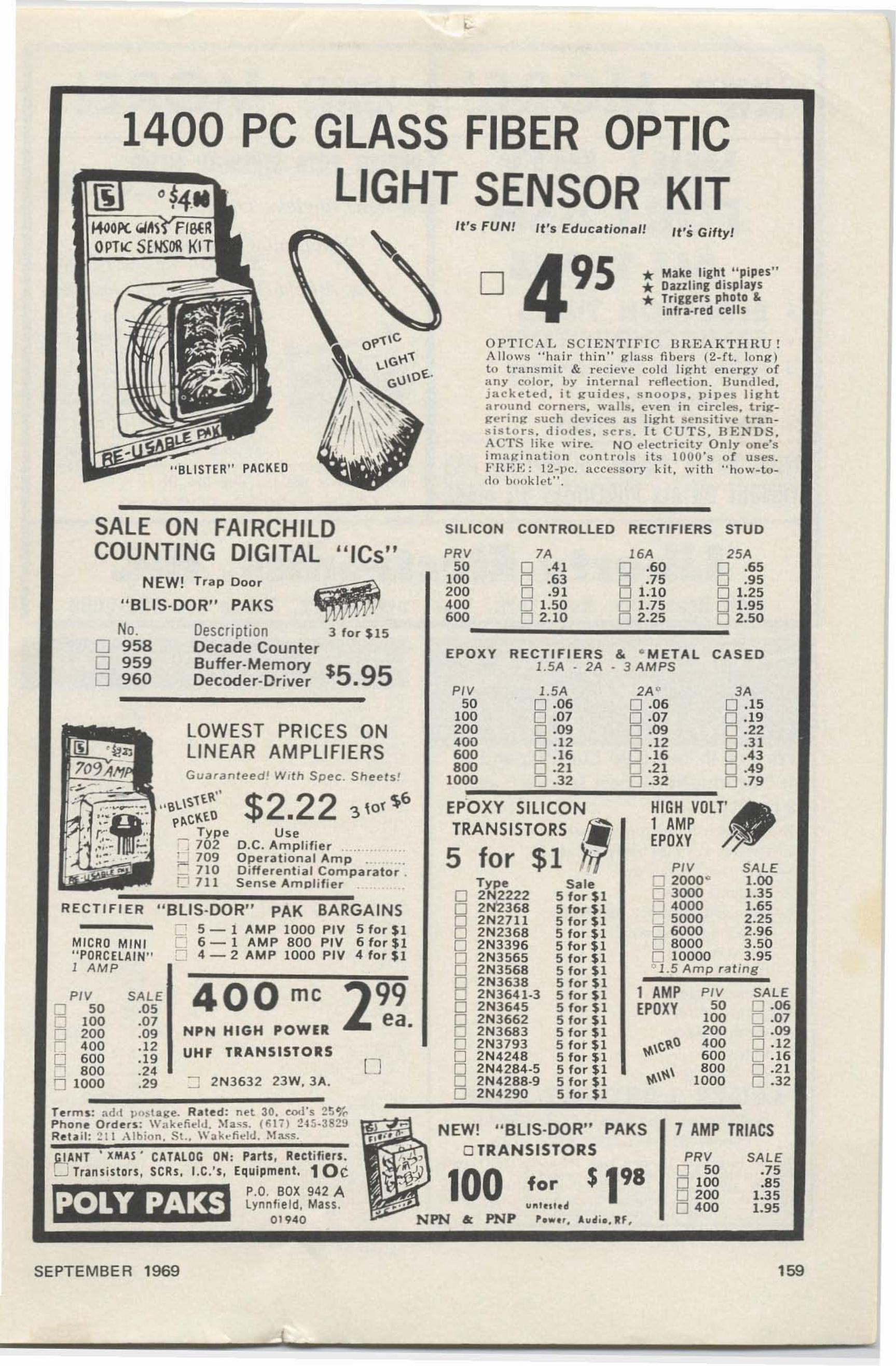
SALE0 ·060 .0 70 ·09
B.1 2.16
0 ·2 10 ·32
3A0 .150 . 190 .220 ·3 10 .430 .490 .79
CASED
PI"50
100200400600BOO
1000
PRV SALEo 50 .75o 100 .B5o 200 1.350 40 0 1.95
7 AMP TRIACS
It's Giffy!
* Make light "pipes"* Dazzl ing displays* Triggers photo &.infra-red cell s
1 AMPEPOXY
2A"0 ·060 ·070 .090 . 120 ·16D .210 ·32
16A
§ .60.75
1.10
B1.752.25
& · M ET AL3 A M PS
9S
Sale5 for $15 for $15 for $15 for $15 for $15 for $15 for $15 for $15far$15 for $I5 for $15 for $15 for $15 for $15 for $15 for $I5 for $1
It's Educational!
for11"'.1'.01
, .... . . A..oI i• • IIF .
7Ao .4 1o .63o .91o 1.500 2. 10
RECTifiERS1.5A • 2A
l. 5A0 ·060 .070 ·090 · 120 . 16D .210 .32
D
It's FUN!
EPOXY
O P T IC A L SC IEN T I F IC BHEAK T H HU!A llows " ha ir t hin" ~lm,H fiber s 12- rt. lOOK)to t ran sm i t & recieve cold Ii~ht ene r~y ofan y color, by in ternul r ...flectio n. Hu ndled ,j ack e t e d . it g-u Id es , s n oo p s , p ipes Iil':"h taruund cor-ne rs, walls , even in circles, triKKt'rin~ s uc h dev Ices l i S light senst t tv e transis to rs , dio de s , s c r s , I t CUTS. B E N DS.ACTS like wire. NO electricity O n ly o n e 'si mnjri nn tion co n trol s i ts 10 UO's o r u s es.!" H ,,; t<: : 12·" c. nccesao t-y kit , w it h "how-t od" hooklet",
PI"50
100200400600BOO
1000
SILICON CONTROLLED RECTIfiERS STUD
EPOXY SILICONTRANSISTORS ••
5 for $1 'It1Typ e
D 2N2222o 2N'2368
B 2N 27112N2368o 2N3396
B 2N3565
B2H356B2N36382 N3 64 1·32N36452N36622N36832 N37932N42482N4284-52N4288-92N4290
PRV 25A50 8 .6 5
100 .95200 0 1.25400 0 1.95soo__...:;:.:;.:::..._~;.::::.__,;;;:0 2.50
100
NEW! "BUS·DOR" PAKSo TRANSISTORS
3 for $15
PACKED
$2.22 3\0,\6
u"D.C. Amplifier " .Op era tional Amp .Differe ntia l Com pa rato r .Se nse Amp lifier .
LOWEST PRICES ONLINEAR AMPLIFIERSGua ranteed ! W ,th Spec . Sheers!
t~"" 6~\'!l"ip~C~lO
Ty pe-; 702; - ~ 709;= 710C1 7 11
NEW! Trap Door
1400 PC GLASS FIBER OPTICLIGHT SENSOR KIT
"
"BUS·DOR" PAKS
No. Descriptiono 958 Decade Countero 959 Buffer-Memory $5 95o 960 Decoder-Driver.
SALE ON FAIRCHILDCOUNTING DIGITAL "ICs"
"BUS·DOR" PAK BARGAINS---- ~ 5 - 1 AMP 1000 PlY 5 for $1
Q 6 - 1 AMP 800 PIV 6 for $1CJ 4 - 2 AMP 1000 PlY 4 for $1
MICRO MINI" PORCElAIN"1 AM P
RECTIFIER
PI" SALE 400 me 2~~.0 50 .0 50 100 .0 7
NPN HIGH POWER0 200 .09rJ 400 .1 2 UHF TRANSiSTORS0 600 .19 [Jn BOO .24,.[) 1000 .29 ::J 2 N3 6 32 2 3 W.3A.
GIANT' XMAS' CATALOG ON; Parts, Rectifiers .[j Transistors , SCRs , I.C,'s, Equipment. 10c
P.O. BOX 942 Alynnfi eld. Mass.
01 9 40
Te rms: ad'l p ostage, R. le d: net 30. coors 2 !j ~~Pho ne O rden : W "keli ..tJ . :'oliil ss . (lH ,) 2 ~ S . 3 8 2~
Ret . il: ~11 A lb ion . S l .. Wakt-ti ..ld. :'oIMS.
SEPTEMBER 1969 159
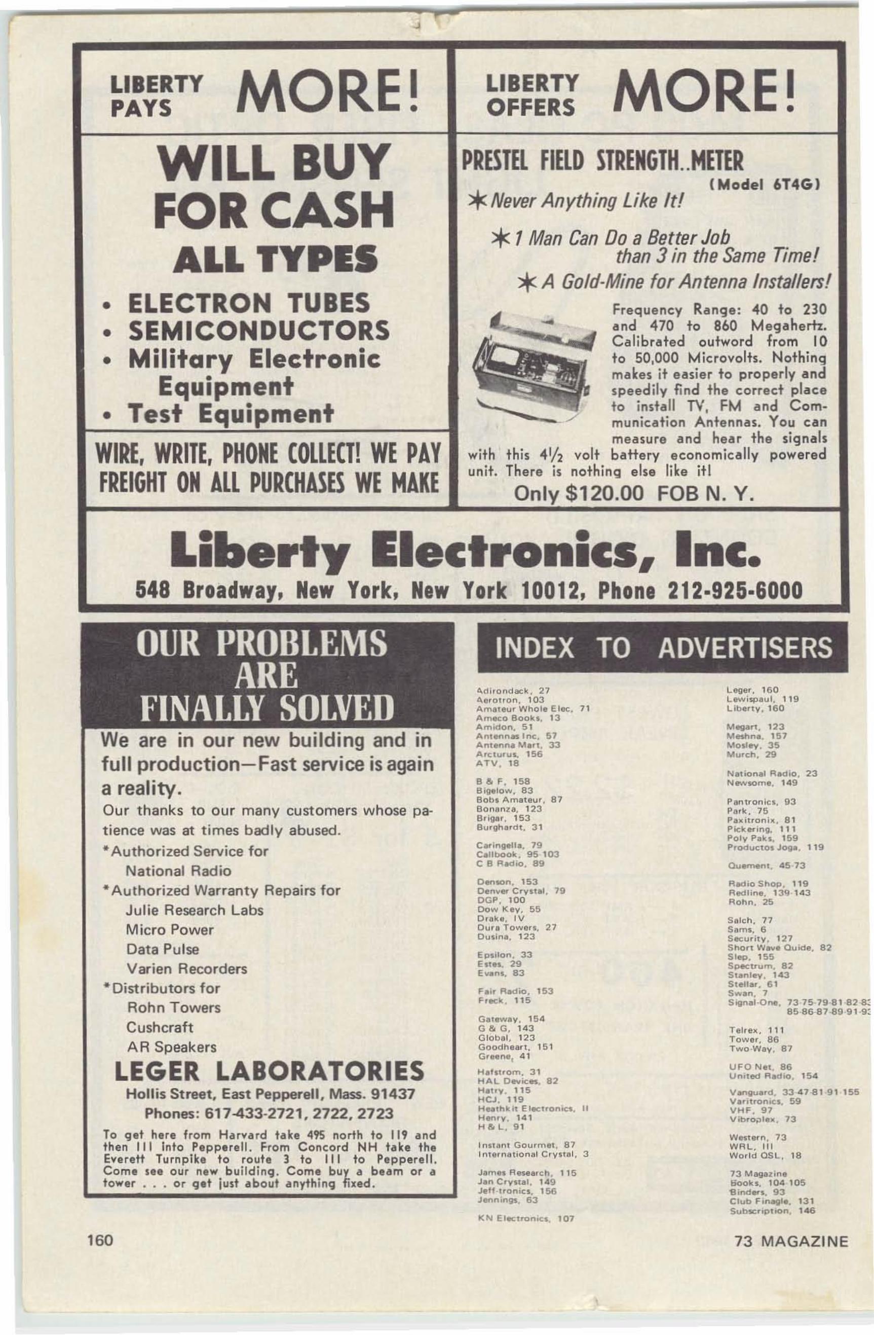
LIBERTYPAYS MORE! LIBERTY
OFFERS MORE!PRESTEL FIELD STRENGTH..METER*Never Anything Like It!
*1Man Can Do a Better Jobthan 3 in the Same Time!*A Gold-Mine for Antenna Installers!
I Model 6T4GI
- Frequency Range : 040 to 230and 470 to 860 Megahertz.Calibrated outward from 10to 50,000 Micro volts. Nothingmakes i t easier to properly andspeed ily find th e correct placeto install TV, FM and Communication Antennas. You canmeasure and hear the signals
this 4112 volt battery e conomica lly poweredThere is nothinq else like it!
Only $120.00 FOB N. Y.
withunit.
WILL BUYFOR CASHALL TYPES
• ELECTRON TUBES• SEMICONDUCTORS• Military Electronic
Equipment• Test Equipment
WIRE, WRITE, PHONE COLLECT! WE PAYFREIGHT ON ALL PURCHASES WE MAKE
Liberty Electronics, Inc.548 Broadway, New York, New York 10012, Phone 212·925·6000
INDEX TO ADVERTISERS
We are in our new building and infull production-Fast service is againa reality.Our thanks to our many customers whose patience was at times badly abused... Authorized Serv ice for
Nat ional Radio.. Authorized Warranty Repairs for
Julie Research LabsMicro PowerData PulseVarien Recorders
* Distributors forAohn TowersCushcraftAA Speakers
LEGER LABORATORIESHollis Street. East Pepperell , Mass. 91437
Phones: 617-433-2721.2722.2723To g et here from Harva rd take 0495 north to 119 andthen III Into Pepperell. From Concord NH take theEverett Turnpike to route ] to III to Pepperell.Com . s•• o ur new bui ld ing . Come buy a beam or at ower . . . Or g.t just about anything fixed .
"cli ,ondock , 27" e,otron. 10 3Am• •• u' Whol. E lec. 71Ameco 800k •. 13Amidon. 5 1An•..,.,n .. Inc , 57Ant..,na M." . 33Arc<u,us. 156ATV . 18
8&F . 1588ig.IO.... , 8380h. Am. 'eur. 8780n.nz•. 1 2 38'ig. r. 1538u,~.rclt. 31
C.,.inlleU•• 79CaUbook. 95 103C 8 R.,"o. 89
Denoon. 153Dan~ar C r yote!. 79OGP. 100Dow ".y. 55D r. ke . I VOur. Towerl, 27DUlin•. 1 23
E...don. 33EIt". 29E~..nl. 83
F.... Redia . 153F reck . 1 15
G.........y . 154G & G. 14 3G lob.l. 1 2 3Goodh..". 1 5 1Gr..n., 4 1
H."trom. 31HAL 0 ...",... 82H.Uy. 11 5HCJ. 1 19H...,hkit ElaclronOcI. IIHan r y . 14 1H & L. 9 1
.n....nt Gourmet. 87In 'e",.,lonal C ry .. .. I. 3
J.m.. R ew.'C h. 1 15J.n C ry...I. 149J I'fI ·lro n iCI . 156JenninlII. 63
"N Elect",nic. , 107
Lege ', 16 0L......i"'. u •. 1 19I.lb a" y .1 6 0
Mag 12 3Mnhn 15 7Malley. 35Murch. 29
N..,ion ..1 Radio. 23N_some. 149
P.ntronlc •. 93Par k. 75Pultroni•• 8 1Pkk .... "'Q. 111POly P.ks. 159ProductOI J09oO. 1 19
au.....n • • 45-73
Re<lio ShOP, 119Redlin•. 13<;1 -1.3ROhn. 25
S . lc h . 77S.ml. 6Secu,i, y. 127Shon W.... auKie. 8251eQ. 155Sp«:tTUm. 82St.nley. 1 43S'*,lar . 61S.....n. 75IQnel-0.,.. 73-75-79-8182-8:
85-86-87-.Q99 1-9:
Telr • • . 111To.... e r . 86r-vewev. 87
U FO N.,. 86un"M! RedlO. 154
Vanllu.,d . 33 47-81 -9 1 15 5V.,ittonicl. 59VHF. 97V ib,o;>'u . 73
W..ter n . 73WRL. II IWoo ld OSLo 18
73 M_.ineI>ool<s. 104 1058indarl. 93C lub F inagle . 13 1SubscrtptlOn. 146
160 73 MAGAZINE

~~~~k:g,J~~.Q.'O• • • · I ....ol".", . .... . CO..,.., I." O
112 VALUE-PACKED PAGES I OUR BIGGEST EVERI
ElectronicEquipmentCATALOG
WORLD RADIO
FREE!The late st in quali ty e lectronic e q ui pment ! Mone y-sa ving bu ys on everything in e lectron ics, including new and excl usive items availabl e o nly atWorld. AND everyth ing in ou r Catalog is ava ilable on ou r easy monthlycredit plan !
SHOP BY MAIL AND SAVE ON - Special Package bUys on name brand Amateur, CB and Hi-Fiequipment selected by WRl experts' Amateur Gear ' CB Equipment · Stereo Hi-Fi' Electronic & Hobby Kits · Tape Recorders and Tape· Walk ie Talkies· Shortwave Receivers• Phonographs' Speakers ' Record Changers ' FM/AM & VHF Radios· Intercoms' PAEquipment· Test Equipment >Antennas · Tubes and Transistors> Automotive Elect ronics• Tools & Hardware> Books >Headphones >Microphones · Wire & Cable · Pa rt s & Batter ies
3415 West BroadwayCounci l Bluffs, Iowa 51501
Cent lemcn :Plt'lU i' semi me your FREE 1970 Catalog.
WORLD RADIO _••Dep'7J--E E45.
••••--------------_ .•• Addre ss •
I City Sta te Zip IL ~
Use our easy monthlycredit plan or yourBonkAmericard orMoster Charge to buyanything in our Catalog!
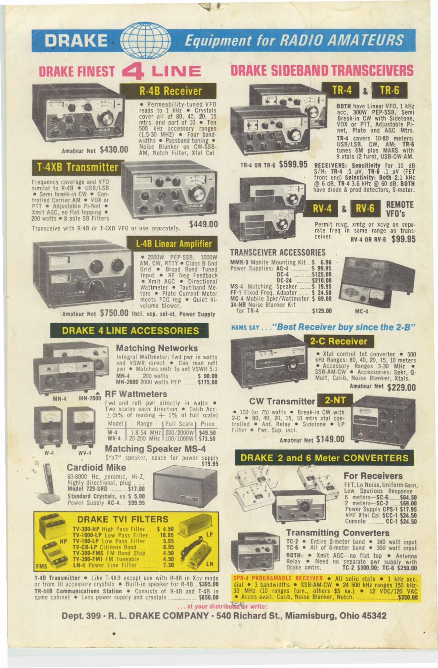
,
DRAKE FINEST 4 LINE DRAKE SIDEBAND TRANSCEIVERS
REMOTEVFO's
TR ·G&
RY·6&
BOTH have linear VFQ, 1 kHzace, 300W PEP·SSB, SemiBreak-in CW with Sidetone ,VOX or PH, Adjustable Pinet , Plate an d AGC Mtn.Ta.,. covers 10-80 meters:USB/ LSB, CW, AM: TR-Itunes 6M plus MARS with9 xta ts (2 turm, USB-CW-AM.
a~CEIVERS : Sensitivity for 10 esS/ N: TR·4 .5 ~V I TR·6 .1 JjV (FETfront end, Selectivity : Botti 2.1 kHz@ 6 dB, TR-4 3.6 kttz @ 60 es. BOTHhave diode & prod detectors, s-meter•
TR·, OR TR·' $599.95
Permit rcvg, Jmtg or xcvg on se para te fr eq in same range as tran sceiver. . RV.4 OR RV·& $99.95
TRANSCEIVER ACCESSORIESMMK-l Mobi le Mounting Kit s 1.91Power Supplies : AC" $ 99.95
DC-4 ... $125.00DC·24 , $210.00
MS·4 Matching Speaker $ 19.95Fr-1 Fi xed rreq. Adapter ._ $ 24 .50MC-4 Mobile Spkr/Wattmeter $ &9.00)4-MB Noi se Blanker Kit
f or TR-4 $1 29.00
$449.00
• Per meabuttr -t uneu vrcreads to 1 kHz • Crysta lscover all of 80, 40, 20, 15mtrs. and part of 10 • Ten500 kHz accessory ranges(I.S-30 MHZ) • Four band·widths . Passband tuning .Noise Blanker on CW·SSBAM , Notch Filter, Xtal Cal
• 2000W PEP·SSB, l 000WAM, CW, RTTY . Class B GndGrid • Broad Band TunedInput • RF Neg Feedback• Xmit AGC • Directi onalWattm eter • t aut-bend Meters • Plate Cu rren t Metermeets FCC reg . Quiet hivolume blower.
Amateur Net $750.00 Incl. sep. sol-st. Power Supply
AmaH ur Net $430.00
Freq uency cove rage and VFQsimilar to R-4B • USB/ l SB• Semi break-in cw • Controlled Carrier AM • VOX orPTT • Adjustable Pi-Net •Xmlt AGC, no flat topping .200 watts . 8 pole SB Filters
trenscetve with R·4B or T·4XB VFa or use separatel y.
• Xtal control 1st conve rter • 500kHz Range s: 80, 40, 20, IS, 10 meters• Accessory Ranges 3030 MHz •SS 8·AM·CW • ~cces sories : Spkr, -QMu lt , Cahb, NOi se Blanker, xtats.
Amll'.. Hot $229.00
""1:"'-'..,••
CW Transmitter
DRAKE 2 and 6 Meter CONVERTERS
,
• 100 (or 75) wa tts • Break-in CW with2-C • 80, 40, 20, 15, 10 mt rs xta! controlled • Ant. Relay • Sidetone • l Pf i lter . Pwr. Sup. incl.
Amateur Net $1 49.00
HAMS SAY .••"Best Receiver buy since the 2-B"
Matching NetworksIntegral Wattmeter: fwd pwr in watt sand VSWR direct • Can read ref lpwr • Matches Jmlr to ant VSWR 5:1MH-4 200 watts $ 90.00MN·2000 2000 watts PEP $115.00
RF WattmetersFwd and re f I pwr directl y In watt s •Two scales each direction . Cali b Ace:·t (5% 01 reading + 1% of full scale)Model Range Fu ll Scale Pricew·e U -S4 MHz 2OO/2000w $49.50WY·, 20 200 MHz l00/1000W $13.50
Matching Spea ker MS-45"1..7" speaker, space for po wer supply
$19.95
A
MN·2000
WV-4
DRAKE TVI FILTERS$ 4.50
1&.955.95&.954.504.501.30
TV·3DD·HP High Pa ss Fi lterTV-10DO·lP Low Pass FilterTV-1DO·LP Low Pass FilterTV-CB ·LP Cit izens BandTY·3DO·fMS f M Band StopTV-300·fMI FM TuneableLN ·4 Power l ine Filter
Cardioid Mike60·8000 Hz, ceramic . Hi·I ,highly direcllonal, PIUI " . "Model 129·SRD ..._..__ 11.00Sta ndard Crystals, ea $ 5.00Power Supply AC-L. $99.95
DRAKE 4 LINE ACCESSORIES
w·,
For ReceiversFET.reNoise,Uniform Gain,low Spurious Response6 meters- SC-& $6·40502 mete rs- SC-2 $69.00Power Supply CPS-1 $11.95VHF Xhl Ca l see-r $24.50Console .._ ce·, $24.50
Transmilting ConvertersTC-2 • Entire z-meter band • 180 watt inputI C-I • All of 6-meter band • 300 watt inputBOTH : - Xmit AGC-no flat top • AntennaRelay - Need no separate pwr supply withDrake xmtrs. 1C-2 $300.00; TC·6 $250.00
1·48 Transmitter. Like T-4XB except use wi th R·4B in xcv mode SPR ·4 PROGRAMABLE RECEIVER . All solid sta te . 1 kHz ace.or f rom 10 accessory crystals . Buil t-in spea ke r for R-48 $395.00 dial . 3 bandwidths . SSB-AM-CW • 24500 kHz ran lies 150 kHz-TR-44B Co mm uniC3tions Stati on • Consists of R-4B and T-4 B in 30 MHz (10 ranges furn.• others $5 ea .) • 12 VOC/J20 'lACsame cabinet . less power supply and crystals .___ __ $1 50.00 • Acces avail : Calib, Noise Blanker, Notch...........•._.._ _$350.00
•.. at your distrib~' write :
Dept. 399 · R. L. DRAKE COMPANY· 540 Richard St., Miamisburg, Ohio 45342
'.
• •
• C d_ 1


