Embed Size (px)
Citation preview

ClassM)&S32-AliBook
Copyrightso tfy3
COPYRIGHT DEPOSIT
The D- Van Nostrand Companyintend this book to be sold to the Public
at the advertised price, and supply it to
the Trade on terms which will not allow
of discount.


ELECTRICALAND
MAGNETIC CALCULATIONSFOR THE USE OF
Electrical Engineers and Artisans, Teachers, Students,
and all others interested in the Theory and Ap-
plication of Electricity and Magnetism
A?AKATKINSON, M.S.
Professor of Physics and Electrical Engineering in
Ohio University, Athens, Ohio.
FOURTH EDITION, REVISED
* *
• • •
NEW YORK:
D. VAN NOSTRAND COMPANY25 Park Place
1913
QCS32
COPYRIGHT „ ig02. IQ03, I913
BY
D. Van Nostrand Company
C. J. PETERS & SON, TYPOGRAPHERSBOSTON, MASS., U. S. A.
CI.A346055
U-01
TABLE OF CONTENTS.
CHAPTER I. page
Explanation of Units I
CHAPTER II.
Relation of Quantities 12
CHAPTER III.
General Laws of Resistance 22
CHAPTER IV.
Electrical Energy 45
CHAPTER V.
Wiring for Light and Power 66
CHAPTER VI.
Batteries 85
CHAPTER VII.
Magnetism ...,,-.... no
iv CONTENTS
CHAPTER VIII.
Relation of Magnetic Quantities 116
CHAPTER IX.
The E.M.F. of Dynamos and Motors 148
CHAPTER X.
Calculation of Fields 171
CHAPTER XL
Elements of Dynamo Design 190
CHAPTER XII.
Alternating Currents 230
CHAPTER XIII.
Alternating Current Distribution 261
PREFACE.
The following pages, both in plan and material, are the
outgrowth of several years of experience in teaching young
men the rudiments of electricity. A large part of the
matter, in fact, was prepared expressly as an introduction
to a course in electrical engineering ; since there was noth-
ing published covering the topics found desirable, and
making use of the method herein employed.
A multiplicity of wordy rules and unexplained con-
stants arbitrarily set down burden the memory unneces-
sarily, are often unintelligible to the reader, and are at
best very clumsy tools with which to work. In the pres-
ent volume, on the other hand, several processes are
brought together wherever possible under a single broad
principle, which is then expressed by means of a formula.
The treatment in this respect aims to be educational.
Through a step by step process principles and formulae
are evolved from facts and principles already understood.
After the law has been clearly developed, and has been
given the most concise, easily remembered, and con-
venient working form, the method of induction gives way
to that of deduction. A series of examples are then
worked out illustrating the application of the principle,
and giving familiarity with its processes. At the end of
the chapters are also lists of original problems for drill
in the mastery of the principles and their application.
VI PREFACE.
It is hoped that the great body of artisans in all the
departments of electrical engineering practice will find in
these pages an invaluable aid in their efforts to acquire
a better working knowledge of the principles underlying
their profession. In a first reading, perhaps the original
problems may be passed over ; also the chapter on the
relation of heat and chemical energy, and possibly a
portion of alternating currents, especially that of long-
distance transmission circuits. Each individual's taste
and particular line of work will largely guide him in his
selection of subjects for special investigation. A careful
study of this little volume, even omitting certain portions
as suggested, will be an excellent schooling for those
busily engaged in the various electrical processes.
It will also be a helpful companion to electrical engi-
neers, superintendents, and all those in the more respon-
sible positions in engineering work. They will find it
valuable in its development of the rules and formulae
employed in their profession and as a handy reference
for the methods of application of these rules and formulae
to practical engineering problems.
Teachers in schools and colleges which devote some
time to the subject of physics may find here a vast num-
ber of examples for class use in teaching electricity, the
most important branch of physics. It will be particularly
useful to teachers in colleges and technical schools which
make a special feature of electricity, either as a reference
book of formulae and examples, or as a text-book for class
drill in those topics treated. Selections may be made of
the topics best suited to particular needs, if not all are
available.
PREFACE. Vll
In the preparation of this book frequent use has been
made of competent authorities. Most of these have been
mentioned in the body of the work, or in the marginal
references.
Mistakes in a book of this nature are inevitable, how-
ever carefully the proof has been read, and the author will
appreciate any corrections sent to him.
This opportunity is taken of thanking our friend and
professor, W. M. Stine, Professor of Engineering in
Swarthmore College, for examination of the manuscript
and valuable suggestions in connection with its publi-
cation. Acknowledgments are also due to Professor
W. B. Bentley, Department of Chemistry, Ohio Univer-
sity, for assistance in reading the proof, and to Messrs.
F. H. Super and N. R. Cunius, Assistants in the Depart-
ment of Physics and Electricity, Ohio University, for the
preparation of the diagrams.
Ohio University,
Jan. /, 1902.
PREFACE TO THE SECOND EDITION.
The author has been gratified by the many appreci-
ative reviews and notices published in reference to the
first edition of this volume. It is not a treatise on Elec-
trical Engineering, but, as its title indicates, attempts to
set forth the methods of solution of those problems in
Electricity and Magnetism which are of most importance
to the electrical engineer and the teacher. As such it
has been most kindly received.
Coming so soon after the publication of the first edi-
tion perhaps not all the errors have been discovered and
corrected, and but few changes are considered necessary,
otherwise.
The chapter on Alternating Currents has been movedto the end of the book, and Chapter XIII., Alternating
Current Distribution, formed from the portion of Chapter
VI., relating to Alternating Currents, added. These modi-
fications will no doubt improve the usefulness of the
book.
Ohio University,
Oct. i, 1902.
PREFACE TO THE FOURTH EDITION
The present edition of this text has been improved in
the following particulars : A considerable number of errors
in the former edition have been noted and corrected in
this ; some terms made obsolete by common usage of a
substitute, such as " duty " and " weber," have been
changed to the modern terms ; in Chapter V constants
are suggested by whose use the rules for wiring, applicable
to carbon lamps, may also be adapted to tungsten lamps
now in common use; also it is suggested on pages 143,
147 and 199 that the original problems in Chapters VIII,
X and XI, in which magnetomotive force or ampere-turns
are required, be worked out by the use of the curves on
page 229, or by the use of the tables given on page 298.
From the curves the value of H corresponding to any
value of B is obtained for each portion of the magnetic
circuit ; each H (gilberts per centimeter) is then multi-
plied by the corresponding length in centimeters, giving
the magnetomotive force, whence the sum of all the
partial magnetomotive forces multiplied by eight-tenths
will give the total ampere-turns required ; that is, ampere-
turns = 0.8 M. From the tables on page 298 the " am-
pere-turns per centimeter'' are obtained direct -
—
whence the ampere-turns for each portion and the total
for the magnetic circuit may readily be computed. These
X PREFACE.
methods will give results only approximately the same
as those obtained by the more cumbersome reluctance
method, for reasons which will at once be apparent.
Their convenience and practicability recommend their
general use for all such computations.
It is to be hoped that those accustomed to the use of
this book, as well as others who may use it, will find it
more satisfactory because of the changes and suggestions
made in this edition.
Ohio University, Athens, Ohio,
Jan. 2, 1913.
ELECTRICAL AND MAGNETICCALCULATIONS.
I.
EXPLANATION OF UNITS.
i. Units. — In every form -of measurement certain
units are necessary as standards of comparison. A quan-
tity of any kind is measured when the number of the
units it contains is determined. Thus a bin of wheat
is measured when the number of bushels it contains is
found, the bushel being the unit. The quantity of elec-
trical flow is measured by expressing the number of
coulombs in it. The expression of a quantity, therefore,
includes the name of the unit employed, preceded by the
number of units ; as 40 volts, or 5 amperes.
2. Fundamental and Derived Units. — Thefundamental
units of any system are those which are basal, not derived
from any other units. There are considered generally
three fundamental units,— the unit of time, the unit of
mass, and the unit of length. In one system these are
respectively, — the second, the gram, and the centi-
meter. These are the units used for all scientific work.
Other units built up by combining these units are called
derived units. Such are units of area involving the sec-
2 ELECTRICAL AND MAGNETIC CALCULATIONS.
ond power of a length, P ; also units of volume being pro-
portional to /3
. Likewise the watt is a derived unit, being
a product; its factors are an electromotive force and a
current, or E X /, each of which in turn is derived.
3. Absolute Units.— If the fundamental units men-
tioned above be used, the system of absolute units based
upon them is called the C.G.S. system, or the centimeter-
gram-second system, from the names of the fundamental
units of the system. Thus the dyne is the absolute unit
of force, being that force which, acting upon one gram
for one second, will give it a velocity of one centimeter
per second. The erg is the absolute unit of work. It is
the wrork done when one dyne acts through a distance of
one centimeter.
It is to be observed that a unit is denned by unit con-
ditions ; that is, by the units of the elements upon which
the unit under definition is based. To illustrate, work
involves two, and only two elements ; namely, force and
distance. Hence, unit work will be defined by unity in
these elements. The erg is the work of one dyne through
one centimeter,
4. The Basis of the Fundamental Units.— {a) Origi-
nally the meter was intended to be the ten-millionth part
of the earth-quadrant through the meridian of Paris,
measured from the equator to the north pole. For practi-
cal purposes, the French government adopted a platinum
standard between whose ends at o° C. the distance should
be one meter. This is known as the " Metre des
Archives." It was made by Borda in accordance with a
government decree passed in 1795. In 1866, the United
EXPLANATION OF UNITS. 3
States government, by Act of Congress, defined the meter
to be 39.37 inches. The ce?itimeter is the one-hundredth
part of the meter ; the millimeter is the tenth part of the
centimeter, or the one-thousandth part of the meter. For
larger measures the kilometer is employed, and is equal to
1000 meters.
(b) Mass is the quantity of matter in a body, while its
weight is the amount of the earth's force of gravity upon
the mass. The mass does not vary, but weight varies
from place to place due to changes in the force of gravity.
Calling the force of gravity g, representing mass by m,
and weight by w, this relation is expressed by
w = mg. (1)
Weight is therefore a function both of mass and the force
of gravity. In the C.G.S. system the unit of mass is
theoretically that of a cubic centimeter of distilled water
at the temperature of its greatest density, 4 C, and is
called the gram. As a practical standard, however, it is
the one-thousandth part of a mass of platinum preserved
in the archives of Paris, called the " Kilogram des
Archives." The reason for using the larger material
standards for length and mass is obvious. The kilogram
has the value in English measure of 2.20462 pounds, or
approximately 2\ lbs.
(c) The second is the -^J^o Pa]rt °f tne average length
of all the solar days taken throughout the year. A solar
day is the interval between two successive transits of the
sun's center across the meridian of a place. These days
vary in length on account of the unequal velocities of the
4 ELECTRICAL AND MAGNETIC CALCULATIONS.
earth in its orbit from day to day. Hence the average of
all is taken throughout the year.
5. Magnetic Units. — ( a ) The Strength of Pole of a
magnet is determined by the force it is capable of exerting
on another pole at a given distance. If m be the strength
of one pole and tnrthat of another at a distance of d, then
the force of attraction or repulsion, as the case may be,
is expressed by the formula,
mm'
in which q is a constant. The force, therefore, varies
directly as the strength of the poles and inversely as the
square of their distance apart. A unitpole is one such as
to repel a similar one at a distance of one centimeter with
a force of one dyne.
(b) Magnetic Field. Any space traversed by magnetic
forces is called a magnetic field. The space between the
poles of a horse-shoe or other magnet is conceived to
be traversed by magnetic lines offorce ; that is, imaginary
lines along which magnetic attraction or repulsion takes
place. If the force is one dyne per square centimeter of
the surface normal to the direction of the lines of force,
we say the field has an intensity of one ; if the force be
10 dynes per square centimeter, the intensity is 10, or 10
lines of force per square centimeter, etc. Intensity of
field is represented by H. If a pole of strength m be
put into a field whose intensity is H, the force tending to
push it along the lines is
F=Hm. (3)
EXPLANATION OF UNITS. 5
(c) Magnetic Moment. The magnetic moment of a
magnet is the product of its strength of pole by its
length, or M = ml. (4)
Suppose a slim magnet of length / be placed at right
angles to the lines of force of a field of intensity H, then
the moment of the couple tending to swing the magnet
around into parallelism with the lines of force will be
F = Htnl = HM. (5)
(d) Intensity of Magnetization. The quotient obtained
by dividing the magnetic moment by the volume of the
magnet is called the intensity of magnetization.
_ M ml m , Ni= v = ti=i- (6)
In other words, it may be defined as the strength of pole
per unit surface of cross section.
(e) Magnetic Induction. When a piece of soft iron is
placed parallel with the lines of force of a magnetic field,
the lines concentrate within the bar, which becomes a
magnet by i?iduction. The end at which the lines enter be-
comes a south pole, the end from which they leave a north
pole. The iron offers a path of less resistance to the mag-
netic lines than air does. This is expressed by saying that
iron has a smaller reluctivity, or a greater permeability,
than air. When speaking of complete magnetic circuits
the terms reluctance and permeance are used instead of the
above, which apply to specific substances. Air is taken
as the standard of permeabilities, its own being therefore
6 ELECTRICAL AND MAGNETIC CALCULATIONS.
unity. The number of lines of force passing through a
given length of different substances is. proportional to
their respective permeabilities, the areas of cross section
being i square centimeter. If H represents the intensity
of the lines in air, and the intensity of induction in a
piece of iron put into the field H be expressed by B, then
under the conditions the permeability of the iron will be
B_
from which B = fxH. (7)
If the bar, say, steel, be already magnetized to intensity
7, when placed in the field Zf, the induction will become
B= IT+qvI. (8)
6. Electrical Units.— There are two systems of electri-
cal units : (1) units founded on the force of attraction of
unlike or repulsion of like charges of electricity, constitut-
ing the electrostatic system; (2) units based on considera-
tions of the magnetic field produced by a current of
electricity flowing in a wire, constituting the electromagnetic
system. All our practical electrical units are derived
from the latter system, which is, therefore, the only one
that will be considered.
( a ) The Unit of Current. The absolute unit of current
is defined as that rate offlow in a conductor bent into the
form of a ring whose radius is one centimeter, which will
exert a force of one dyne at the centerfor each centimeter of
the arc. Hence, the radius being unity, the whole cir-
cumference, 27rr, will be 6.28 cm., and the total force
EXPLANATION OF UNITS. 7
exerted at the center 6.28 dynes. This unit is the abso-
lute ampere. Suppose, now, a loop of any radius r be
made to carry any number of absolute amperes /; the
force at the center of the loop in dynes will be
2 irrl 2 ttI I^=-72-=— = 6 - 28 "- (9)
If the circular coil have n turns instead of one, the force
becomes
2iznlF=——- (10)
In case the wire is wound in a long solenoid whose length
/ is great compared with its radius, the force inside it
will be
F=—r— ( IJ )
This unit is large, and for practical purposes the ampere
is chosen equal to -^ of the above unit, so that if one
practical ampere flow in the loop as described the force
at the center due to the whole circumference will be
6.28 X io_1 = 0.628 dyne.
The Chamber of Delegates of the International Con-
gress of Electricians which convened in Chicago, Aug.
21, 1893 (World's Fair), defined the unit of current
as follows :
As the unit of current, the international ampere is recommendedto be adopted which is one-tenth of the unit of current of the C.G.S.
system of electromagnetic units, and which is represented sufficiently
8 ELECTRICAL AND MAGNETIC CALCULATIONS.
well for practical use by the unvarying current which, when passed
through a solution of nitrate of silver in water, in accordance with
accompanying specifications, deposits silver at the rate of 0.001118
gram per second.
If the solution be copper sulphate the international
ampere will deposit copper at the rate of 0.0003284 gram
per second under specific conditions. These constants,
0.001118 and 0.0003284, are called the electrochemical
equivalents of silver and copper, respectively. Sub-divis-
ions of the ampere are often used for the measurement of
very small currents ; as the milliampere, or the TqW of
the ampere, and the microampere, or the y^olxffoTr °f tne
ampere.
(b) The Unit of Quantity. The quantity of electricity
conveyed is expressed by the product of the current and
the time flowing in seconds. Unit quantity will be trans-
ferred when one ampereflows for one second. This is called
the coulomb and is equal to io_1 x 1, or io_1 C.G.S. units.
Suppose 5 amperes flow for 4 seconds; £=5x4 = 20
coulombs, or 20 X io_1 = 2 C.G.S. units of quantity.
Microcoulombs are used to express small quantities.
(c) The Unit of Electromotive Force. The general defini-
tion of force is that which tends to produce or modify
motion. By analogy, one would say that electromotive
force is that which tends to move or transfer a quantity of
electricity. It is analogous to pressure produced by a
head of water, as in a standpipe. If a tap be opened
somewhere in the street water-main there will be a flow
through the pipe because the pressure at the tap is less
than that at the standpipe. Let Exbe the pressure at the
EXPLANATION OF UNITS. 9
latter, and E2 the pressure at the tap. The quantity flow-
ing out is proportional to E1—E2
= E. This difference of
pressure, which may be represented simply by E, may be
called the watermotive force. Similar conditions exist in
the phenomenon of electromotive force, or electric pres-
sure. All that the battery or dynamo does is to set up a
difference of potential, or difference of electric pressure
between two points, called electromotive force E. The
phenomenon of the equalization of this difference in
a circuit is what we mean by current flow. Now, if
the opposing forces, or resistance, be unity, the unit of
E.M.F. is that which will produce unit flow of current
through the circuit.
The absolute unit of force being very small, the practical
unit of E.M.F. is chosen equal to 100,000,000 or io8 C.G.S.
units, and is called the volt. The International Congress,
mentioned before, recommended for adoption,
As the unit of electromotive force, the international volt, which is
the E.M.F. that steadily applied to a conductor whose resistance is
one inter7iational ohm, will produce a current of one international
ampere, and which is represented sufficiently well for practical use by
\%%4 °f tne E.M.F. between the poles of the voltaic cell, known as
Clark's Cell, at a temperature of 15 C, and prepared according to
specification.
The Clark cell has therefore 1.434 international volts of
E.M.F. The Carhart cell, which is much superior to the
old Clark, is now much used in this country as a stan-
dard. It has an E.M.F. of 1.44 volts at 15 C.
One volt will be generated in a conductor which is
moved across a magnetic field so as to cut the lines of
force at the rate of io 8 per second.
10 ELECTRICAL AND MAGNETIC CALCULATIONS.
( d ) The Unit of Resistance. Resistance to the flow of a
current is of the nature of an opposing force. The unit
of resistance is such that one volt of E.M.F. will cause
current to flow through it at the rate of one ampere
per second. The practical unit is chosen equal to io9
C.G.S. units of force and is called the ohm. The adopted
international ohm
Is based upon the ohm equal to io9 units of resistance of the C.G.S.
system of electromagnetic units, and is represented sufficiently well
for practical use by the resistance offered to an unvarying electric
current by a column of mercury at the temperature of melting ice,
14.4521 grams in mass, of a constant cross sectional area, and of the
length 106.3 centimeters.
For practical standards, coils of constantan or manga-
nin wire are wound on spools, standardized and placed in
a suitable box, the coils being connected to brass bars on
the top, so that by using plugs any resistance within the
capacity of the box can be obtained. The megohm, or
1,000,000 ohms, is used in the measurement of high resis-
tances, such as the resistance of insulators. For very
small resistances the microhm, or T o onm *s used.
( e ) The Unit of Capacity. If one coulomb of electricity
be stored in a recipient, for instance, in a coil of insulated
wire, or in a system of flat parallel conductors, adjacent
ones insulated from each other, called a condenser, and if
this quantity tends to escape with an E.M.F. of one volt,
the capacity of the recipient or condenser is unity. This
unit is the farad. Expressed in another way, it is the
capacity such that one volt will store in it one coulomb of
electricity. For all ordinary capacities the microfarad, or
EXPLANATION OF UNITS. II
T<nr<io oo °f tne ^ara(i is used, the farad being very large,
io" 9 C.G.S. units.
The capacity of the earth is Too§ooo farad, 'or 636
microfarads. A Leyden jar with a total tinfoil surface of
1 square meter, and glass 1 millimeter in thickness, has a
capacity of FV microfarad.
(f ) The Unit of Power. The unit of electrical power is
called the watt, and is the energy required to move one
ampere per second through one ohm resistance. In other
words, one volt of E.M.F. delivering one ampere of current
per second represents a power of one watt. The watt is
equal to io7 ergs per second of C.G.S. units. The horse-
power is 33,000 foot-pounds of mechanical work per minute.
The watt is T^g of the horse-power, and 1 H.P. = 746
watts.
(g) The Unit of Work. The unit of work is done whenone watt of energy is expended per second, and is called
the joule, which is also equal to 10 7 ergs. Joules of work
are obtained by multiplying watts of power, or energy, by
seconds of time.
(h) The Unit of Induction. The induction is unity
when the E.M.F. induced is one international volt,
while the inducing current varies at the rate of one inter-
national ampere per second. This unit is called the
henry, and is io9 C.G.S units.
These international electrical units were legalized byAct of Congress, approved by the President, July 12, 1894,so that they take their place with other standards of
weights and measures.
12 ELECTRICAL AND MAGNETIC CALCULATIONS.
II
RELATION OF QUANTITIES.
7. Ohm's Law.— The simplest perhaps, and yet the
most important relation of electrical or magnetic quanti-
ties to each other is that expressed in Ohm's law. This
law expresses the relation of E.M.F., current, and resist-
ance. Putting / for current, E for E.M.F., and R for
resistance, the law* is expressed by the formula,
Hence, current is obtained by dividing electromotive force
by resistance. From the above formula, by simple trans-
position, or by the rules of simple division, we obtainp
E = 7R, and R = — • In words, these mean that the
E.M.F. is equal to the product of current and resistance, and
that resistance is equal to the quotient of E.M.F. by current.
Example.— How much current in amperes will flow
through an incandescent lamp whose resistance is 200
ohms, when an E.M.F. of no volts is applied to it ?
Solution.— /= — = = 0.55 ampere.R 200
Example.— A battery has a resistance r of 3 ohms
;
what is its E.M.F. if it causes a current of 0.05 amperes
to flow through an external resistance equal to 60 ohms ?
RELATION OF QUAWTITIES. 1
3
Solution.— E = / (R + r) = 0.05 (60 + 3) = 3.15
volts. #
Example. — Find the resistance of an arc street lamp
when a voltage of 50 is required to send 7 amperes
through it.
Solution. — R = — = ^— = 7 - ohms./ 7 7
Expressed in C.G.S. units, ^ = io8, R = io9
, andC 8
1 =z —= —- = io-1
or yL. That is, the ampere is the
r\j- of the C.G.S. electromagnetic unit of current.
8. Quantity, Electromotive Force and Capacity. —Example.— How many coulombs of electricity will flow
through an incandescent lamp whose resistance is 200
ohms, when an E.M.F. of no volts is applied to it for
2 seconds?
Solution. — Q=Ixt=-= X /= X 2 = 1.1 coulombs.R 200
Example.— A glass plate has a square of tinfoil pasted
on each side, thus forming a storehouse or condenser.
A battery whose E.M.F. is 10 volts is connected to both
sides by wires, and thus gives it a charge of 0.00000000
1
coulomb = 0.00 1 microcoulomb : what is the capacity of
the receptacle ?
Solution.— From obvious considerations the quantity
stored will depend on the pressure applied and the capa-
city of the storehouse : that is
Q=£C. (13)From this
_ Q 0.000000001C = -=, = = 0.0000000001 faradE 10
= 0.000 1 microfarad.
14 ELECTRICAL AND MAGNETIC CALCULATIONS.
Example.— How many volts will be required to charge
a condenser whose capacity is 0.5 microfarad with 2.5
microcoulombs of electricity ?
Solution.— From equation (13) E = ~> Hence, in
2 c
this case, E =— = 5 volts, the required E.M.F. Or,
since 2.5 microcoulombs = 0.0000025 coulomb, and 0.5
r i r i ^ 0.000002 Cmicrofarad =0.00000015 farad, E = - = c volts,
0.0000005as before.
Example.— Find the quantity in microcoulombs which
a cell of 1.8 volts E.M.F. will store in a condenser whose
capacity is 0.1 microfarad.
Solution.— Q —EC = 1.8 X 0.1 = 0.18 microcoulomb.
Example.— Find the value of the last answer in abso-
lute C.G.S. units.
Solution. — The coulomb = io _1 C.G.S. units of
quantity. 0.18 microcoulomb = 0.00000018 coulombs =0.00000018 X io_1 C.G.S. units.
9. Power and Work. — Example.— A storage battery
has an E.M.F. of 26 volts; assuming the internal resist-
ance r to be 2 ohms, and the external resistance R to
be 50 ohms, how many joules of work will it do in 30
minutes ?
r E 2 6Solution. — 30 mm. = 1800 sec. I = — =
R 2 + 50
\ ampere. Watts = E X / = 26 x^ = i3. Joules
watts X seconds = 13 X 1800 = 23,400 joules.
RELATION OF QUANTITIES. I 5
Or, Watts = — = — = 1 x ; andR + r 52°'
1800 x 13 = 23400 joules.
Example.— If the indicator shows that an engine is
developing 30 H.P., what is the output of the dynamo to
which it is attached, neglecting all losses in both engine
and dynamo ?
Solution.— 30 H.P. = 30 x 746 = 22,380 watts= 2 2.38
kilowatts, or K.W.
Example. — Suppose the above dynamo supplies 400
lamps at no volts: how much current must each lamp
require, and how much work is done in each per night of
10 hours ?
Solution.— 22,380 watts -5- no volts = 203.45 am-
peres. This amount is for 400 lamps. Hence each will
receive 203.45 -s- 400 = 0.508 ampere. no volts X0.508 = 55.88 watts per lamp. 10 hours = 10 X 60 X
60 = 36,000 seconds. Hence the total work done = 55.88
X 36,000 = 2,011,320 joules per lamp.
10. The Magnetic Relations of Current. — Example. —Let a circular loop of wire having a radius r of 5 cm.
carry 10 C.G.S. amperes of current; how much force in
dynes will be exerted at its center ?
Solution.— F— = 6.28 -= 6.28 x —r r 5
= 12.56 dynes. See equation (9).
Example.— How many international amperes will be
\6 ELECTRICAL AND MAGNETIC CALCULATIONS.
required in a circular coil of 20 turns, radius of coil
10 cm., to produce a force of 125.6 dynes at its center?
Solution.— From (10), F = 6.28— and /=r 6.28 n
Therefore /= *° *25 ' = 10 C.G.S. units. But the
6.28 X 20
international ampere is io" 1 C.G.S. units. Therefore
10 C.G.S. amperes = 10 -5- io_1 =100 amperes.
Example. — How many turns of wire will be necessary,
and on what radius wound, to produce a force of 125.6
dynes at the center when carrying 1 ampere ?
Solution.— F= = 12 c.6.lor D
n 12C.6 x 10 i2c6Hence - = — -— = -—^ = 200.
r 2 -kI 6.28 X 1
An indefinite number of answers is obviously possible.
Within reason, however, a comparatively small number of
solutions is permissible. For instance, make n = 400 ;
then r = 2 cm. Or say n = 800, whence r = 4 cm.
Again, n may be 1000 and r = 5.0 cm.
Example. — How many dynes of force will be exerted
inside a solenoid, or long coil, whose length is 20 cm.,
and the number of whose turns is 100, when it carries 10
amperes of current ?
Solution.— From (11),
7? = 4?r = (12.56 X 100 X — J -4- 20 = 62.8 dynes.
11. Electrolytic Effects. — Example.— How many am-
peres of current have been flowing for 30 minutes when
RELATION OF QUANTITIES. 1
7
the amount of silver deposited by it upon the negative
plate, or cathode, is found to be 0.0040248 gram ?
Solution. — The current multiplied by the amount
that 1 ampere in 1 second deposits, and this product by
the time in seconds, gives the total weight deposited.
Briefly,
W=Izt, (14)
in which W is the weight in grams deposited on the
cathode ; z is the weight deposited per second by 1 am-
pere ; and /is the time in seconds that the current is
passing through the solution of silver nitrate, AgN03 .
In this problem, / = 30 X 60 = 1800 seconds; z =0.001118 gram per ampere per second, or the electrochem-
ical equivalent of silver; w = 0.0040248 gram. Hence
,. W 0.00402481 =— = — = 0.002 amp.
zt 0.001118 X 1800
Example. — How long must 1 ampere flow through a
solution of copper sulphate, CuS0 4 , with copper elec-
trodes, cathode, and anode, to deposit 0.3284 gram of
copper ?
Solution. — From (14),
W 0.3284 „ .
/ = —=- = — = 1000 sec. = 16 mm. 40 sec.Iz 1 X 0.0003284
The electrochemical equivalent of copper is 0.0003284
gram per ampere per second.
Example. — How much water, H20, will be decom-
posed, that is, separated into its elements of O and H, by
5 amperes flowing between platinum electrodes for 60
minutes ?
1 8 ELECTRICAL AND MAGNETIC CALCULATIONS.
Solution. — The electrochemical equivalent of H =0.00001038 gram; of 0=0.00008283 gram. Hence1 ampere will decompose in 1 second, 0.00001038 +0.00008283 = 0.00009321 gram of water. Therefore,
(14), W= Izt = 5 X 0.00009321 X 3600 = 1.67778 grams
= 1.67 cubic centimeters at 4 C.
12. Original Problems.— 1. What must be the external
resistance of a circuit so that a battery of 1.8 volts
E.M.F. and J ohm internal resistance will send 1.5 am-
peres through it ?
jR = 1 ohm.
2. An incandescent lamp has a resistance, when hot,
of about 220 ohms, and requires 1 ampere of current.
If the dynamo has a resistance of -^ ohm, how manyohms may the lead wires have if the voltage of the
dynamo is 111 ?
R = 1.9 ohms.
3. What must be the E.M.F. of a generator to supply
40 lamps each requiring ^ ampere, the resistance of the
generator being 0.1 ohm, so that each lamp, resistance
220 ohms, shall get its full current, assuming the wires to
have a resistance of 0.5 ohm ?
E = 122 volts.
4. A storage battery consists of 10 cells in series, each
giving 2 volts E.M.F. and having \ ohm internal resis-
tance ; the external circuit consists of two resistance
coils in series, one of 5^ ohms, the other 8 ohms ; how
many amperes of current will flow in the circuit ?
/= 1.25 amperes.
RELATION OF QUANTITIES. 1
9
5. When an E.M.F. of no volts is applied to a bank
of 55 incandescent lamps in parallel, 27.5 amperes flow
in the circuit ; how many ohms resistance in the bank ?
How does this compare with the resistance of a single
lamp ? What does this last illustrate ?
R = 4 ohms.
One lamp has ^f& =55 times
as much as 55 lamps.
6. How many coulombs would be used in the bank, in
a 6 hours' run, and how much must be charged per
ampere-hour in order to make the income equivalent to
40/ per lamp per month, the month consisting of 30
days, and 6 hours' run each day ?
Q == 594,000 coulombs.
Price = 0.44/ per ampere-houi.
7. A cell whose E.M.F. is. 1 volt is used to charge a
condenser which is afterwards discharged through a
circuit in which is a milliamperemeter. The discharge
required 1 second and the milliammeter read y1^ milliam-
pere. Find the capacity of the condenser in microfarads.
C= 100 mf.
8. What must be the E.M.F. of the charging battery
when it is required that a condenser whose capacity is
^ microfarad, on discharge gives 0.000002 coulomb
through the ballistic galvanometer ?
E = 6 volts.
9. There are 500 lamps, no volts, 220 ohms each in a
certain building, and they burn 5 hours out of each 24.
How much must the company furnishing the power
20 ELECTRICAL AND MAGNETIC CALCULATIONS.
charge per watt-hour, meter rates, in order that it may
realize the equivalent of 50/ per lamp per month, flat
rate, assuming 30 days per month ?
Price 0.0061/ per watt-hour.
10. A dynamo generates 116 volts, of which no volts
are required in the lamps, the other 6 being necessary
to pass the current through the machine and line. Thelamps have a resistance each of 220 ohms, and there are
40 of them in parallel. What per cent of the watts is
spent in the lamps, and what per cent as waste in the
machine and line ?
Per cent in lamps = 94.8.
Per cent in waste = 5.2.
11. Find the H.P. of the machine in problem 10, and
the H.P. used in the lamps.
H.P. of machine = 3.1.
H.P. of lamps = 3 —
.
12. Reduce the machine energy in 10 to C.G.S. values
and to joules of electrical work.
Joules per second = 2320.
Ergs per second = 2320 X io7.
13. How many turns of wire will be necessary to make
a solenoid 2 cm. diameter and 50 cm. long so that
5 amperes will produce a field within which the force
shall be 62.8 dynes ?
n = 500 turns.
14. Determine the amount of current that must flow in
a circuit in which is a silver voltameter so that the
RELATION OF QUANTITIES. 21
cathode which weighs before passing the current 26.7571
grams shall weigh, after passing the current 1 hour,
26.9128./= 0.03868 ampere.
15. The above current passed through a tangent
galvanometer whose deflection was 53.5° = 6. The law
of the tangent galvanometer is /= K tan 6, where / is
the current, K is the galvanometer constant, or the
current necessary to cause a deflection whose tangent is 1
.
Find K.K = 0.0286 ampere.
16. Find the constant K of a small portable galvanom-
eter in series with a copper voltameter, when the fol-
lowing observations were taken : weight of cathode before
test, 4.82465 grams ; after passing current 30 minutes,
weight was 4.831 grams ; deflection, 6 = 53 .
K = 0.0081 1.
22 ELECTRICAL AND MAGNETIC CALCULATIONS.
III.
GENERAL LAWS OF RESISTANCE.
13. The Relation of Resistance to Length and Area. —Experiment shows that the electrical resistance of a
conductor varies directly with its length, the kind of
material, and inversely with its cross sectional area.
Analogy to the flow of water in iron pipes teaches us the
same relation. The longer the pipe, the greater the resis-
tance to flow ; the rougher or the more crooked the pipe,
the greater the resistance ; the larger the pipe, also, the
less the resistance, and the greater the flow. Stating these
relations by means of a formula, we have
R = KL (xs)
in which R is the resistance, / the length, a the area of
cross section, and K is a constant depending on the
material of the wire, and means the resistance in ohms
of unit dimensions of the material. If the length is
expressed in feet and the area in circular mils, as it is
usually in estimating the resistance of wires, then Kis the resistance of a mil-foot ; that is, the resistance of
a piece 1 foot long and 1 mil in diameter, or 1 circular
mil in cross sectional area. A mil is the T oV °f an mcn>
and circular mils are obtained by simply squaring the
diameter in mils. Square mils are then obtained, if neces-
sary, by multiplying circular mils by 0.7854.
GENERAL LAWS OF RESISTANCE. 23
In comparing two wires in order to obtain any one of
the four quantities in (15), it will be more convenient to
write down the formula for each wire, using subscripts to
denote wire No. 1 and wire No. 2, then after substituting
the given terms in each case, take the ratio of the two
equations. For example, for wire No. 1 :
Rx= Kx
— (1), and for wire No. 2 likewise,
R2= K2
— (2). Or if areas are to be expressed in cir-
cular mils as is usually better,
Rx= K
x -^ (1) for wire No. 1, andax
R2= K2 -^ (2) for wire No. 2. Now taking the ratio
a2
of (0 and co. we have
a^ X h X
d? (3)-
Example.— A length of 1000 feet of wire 95 mils in
diameter has a resistance of 1 .
1 5 ohms ; what is the diam-
eter of a wire of the same material whose resistance is
5.045 ohms for 500 feet?
Solution.—Rx= 1.15 ohms; R2
= 5.045 ohms.
lx = 1000 ft. ; l2 = 500 ft.
Kx= K2 \ d
x= 95 mils ; d2
= ?
Using (3) above, and making the proper substitutions,
1. 15 1000 K2 ^X — X == Whence, transposing,5.045 500 2 ^
d£ = — — = 1028.617 cir. mils, and2 X 5.045
d2 = V1028.617 = 32 mils.
24 ELECTRICAL AND MAGNETIC CALCULATIONS.
Example.— Find the resistance of 500 yards of cop-
per wire 165 mils diameter, the resistance of 1 mile, 230
mils diameter, being 1 ohm.
—
Day.
Solution.— R1= ? ; R2
= 1 ohm,
4= 500 yards;
/
2= 1760 yards; ^=165 mils; ^ = 230 mils.
As before,
^ = ^y^y^ = ^ = 5°° y ^1 y i^_R2" 4 ^i <*?' 1 " 1760
AJCi * 76?'
Whence Rx= 0.55 ohm.
For the comparison of the properties of substances, and
especially of electrolytes, K, the specific resistance, is gener-
ally expressed in microhms per cubic centimeter, instead of
in ohms per mil-foot. The microhm is the one-millionth of
one ohm.
Example.— The specific resistance of copper per cubic
centimeter is 1.6 16 microhms; find the resistance of 10
meters of this wire 2 millimeters in diameter.
Solution.— Rx= 1.6 16 microhms ; R2 = ?
7T
4= 1 cm.; /2=iooo cm.; a1=isq.cm.;a2
=- X(T%)2sq. cm.
X2 = JC1 ; 7T = 3.1416.
Using the same formula as before,
1.616 1 Kx' IT
R2" 1000 Kx
100
Whence
1.616X100X1000 . , ,
R2= - = 51,438 microhms = 0.05 ohm.
GENERAL LAWS OF RESISTANCE. 25
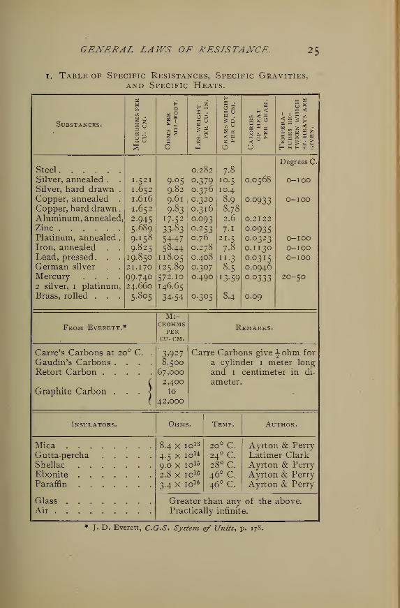
i. Table of Specific Resistances, Specific Gravities,and Specific Heats.
Substances.
H 5K .
'J 3M U
. w
sa
-1
i I X< a >p6 m »
? w zBU £ H
« 3 £
'/3
<: .
„ a za I h
Steel
Silver, annealed .
Silver, hard drawnCopper, annealedCopper, hard drawnAluminum, annealedZinc
Platinum, annealedIron, annealedLead, pressed. .
German silver
Mercury . . .
2 silver, i platinumBrass, rolled . .
1.521
1.652
1.616
1.652
2.945
5.689
9.158
9.825
19.850
21.170
99.74024.660
5.805
9.05
9.82
9.61
9.83
17.52
33.83
544758.44
118.05
125.89
572.10
146.65
34-54
0.282
0.3790.3760.320
0.316
0.093
0.2530.76
0.278
0.408
0.307
0.490
0.305
7.8
10.5
10.4
8.9
8.78
2.6
7-i
21.5
7.8
"•38.5
J3-59
8.4
0.0568
0.0933
0.2122
0.09350.03230.1
130
0.0315
0.0946
0.0333
0.09
Degrees C.
O-IOO
O-IOO
O-IOOO-IOOO-IOO
2O-5O
From Everett *
Mi-crohmsPER
CU. CM.
Remarks.
Carre's Carbons at 20 C.
Gaudin's Carbons . . .
Retort Carbon ....Graphite Carbon
3>9^78,500
67,000
2,400to
42,000
Carre Carbons give |-ohm for
a cylinder 1 meter long
and 1 centimeter in di-
ameter.
Insulators. Ohms. Temp.
20° C.24° C.28° c.46° c.
46° c.
Author.
Mica . . .
Gutta-perchaShellac . .
Ebonite . .
Paraffin . ,
GlassAir .
8.4 x 10
4.5 X 10159.0 X 10
2.8 x io16
3.4 X 10¹⁶
Ayrton & Perry
Latimer ClarkAyrton & Perry
Ayrton & PerryAyrton & Perry
Greater than any of the above.
Practically infinite.
J. D. Everett, C.G.S. System of Units, p. 178.
26 ELECTRICAL AND MAGNETIC CALCULATIONS.
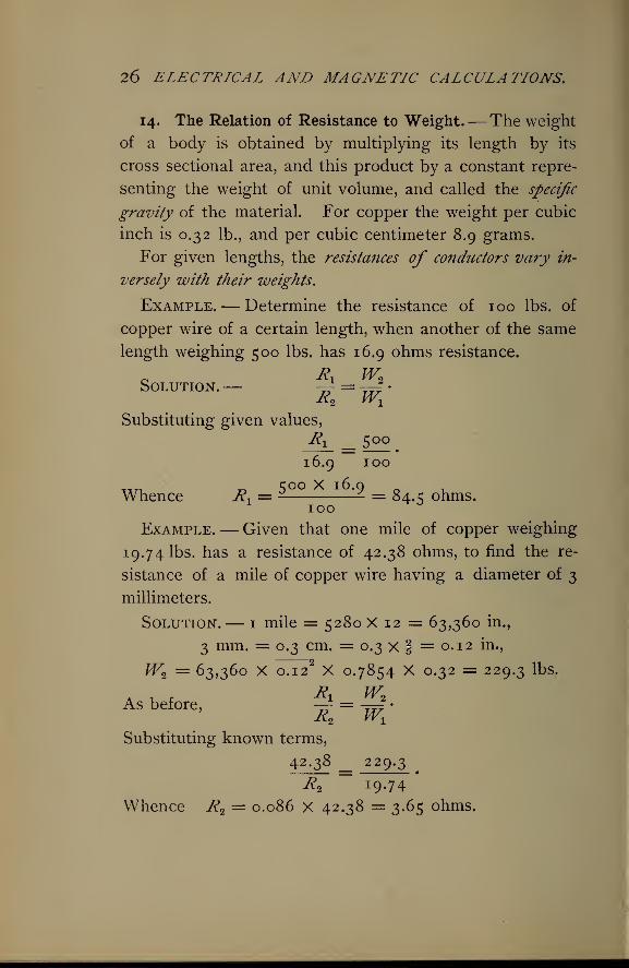
14. The Relation of Resistance to Weight.—The weight
of a body is obtained by multiplying its length by its
cross sectional area, and this product by a constant repre-
senting the weight of unit volume, and called the specific
gravity of the material. For copper the weight per cubic
inch is 0.32 lb., and per cubic centimeter 8.9 grams.
For given lengths, the resistances of conductors vary in-
versely with their weights.
Example.— Determine the resistance of 100 lbs. of
copper wire of a certain length, when another of the same
length weighing 500 lbs. has 16.9 ohms resistance.
Solution.— —- = —4 •
R2 Wx
Substituting given values,
Ri = 500
.
16.9 100
Tun r^ S°° X I ^'9 o 1.Whence Rx= = 84. c ohms.
1 100 °
Example.— Given that one mile of copper weighing
19.74 lbs. has a resistance of 42.38 ohms, to find the re-
sistance of a mile of copper wire having a diameter of 3
millimeters.
Solution.— 1 mile = 5280 X 12 = 63,360 in.,
3 mm. = 0.3 cm. = 0.3 x f = 0.12 ku,
W2= 63,360 X 0.12
2X 0.7854 X 0.32 = 229.3 lbs.
As before, \ =Wt
'
Substituting known terms,
42.38 _. 22 9-3.
R2 19.74'
Whence R2= 0.086 X 42.38 = 3.65 ohms.
GENERAL LAWS OF RESISTANCE. 2J
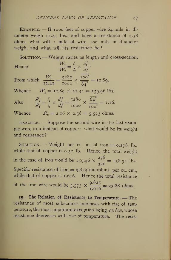
Example.— If iooo feet of copper wire 64 mils in di-
ameter weigh 12.41 lbs., and have a resistance of 2.58
ohms, what will 1 mile of wire 100 mils in diameter
weigh, and what will its resistance be ?
Solution.— Weight varies as length and cross-section.
Hence —-. = j X -~ •
"2
_ , . . JV2 5280 100From which — = x -== = 12.80.
12.41 IOOO 61"
Whence W2= 12.89 X 12.41 = 159.96 lbs.
Also f =f x §! = 5l8o x^ = 2 . l6 .
y?! ix a2
* 1000 Too
Whence R2= 2.16 X 2.58 = 5.573 ohms.
Example.— Suppose the second wire in the last exam-
ple were iron instead of copper ; what would be its weight
and resistance ?
Solution. — Weight per cu. in. of iron = 0.278 lb.,
while that of copper is 0.32 lb. Hence, the total weight
in the case of iron would be 159.96 x —^— = n8qi lbs320 ° y
Specific resistance of iron = 9.825 microhms per cu. cm.,
while that of copper is 1.6 16. Hence the total resistance
of the iron wire would be 5.573 x 9 ' *\ = 33.88 ohms.
15. The Relation of Resistance to Temperature. — Theresistance of most substances increases with rise of tem-
perature, the most important exception being carbon, whoseresistance decreases with rise of temperature. The resis-
28 ELECTRICAL AND MAGNETIC CALCULATIONS.
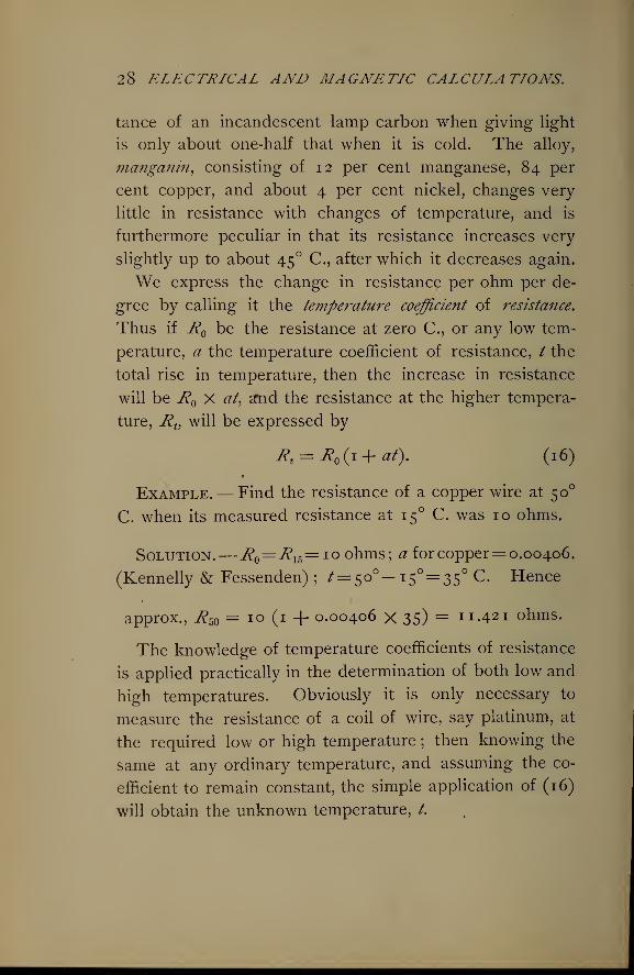
tance of an incandescent lamp carbon when giving light
is only about one-half that when it is cold. The alloy,
nianganin, consisting of 12 per cent manganese, 84 per
cent copper, and about 4 per cent nickel, changes very
little in resistance with changes of temperature, and is
furthermore peculiar in that its resistance increases very
slightly up to about 45 ° C, after which it decreases again.
We express the change in resistance per ohm per de-
gree by calling it the temperature coefficient of resistance.
Thus if J? be the resistance at zero C, or any low tem-
perature, a the temperature coefficient of resistance, / the
total rise in temperature, then the increase in resistance
will be J? X at, a*nd the resistance at the higher tempera-
ture, JRt , will be expressed by
Rt= R (i+at). (16)
Example.— Find the resistance of a copper wire at 50
C. when its measured resistance at 15 C. was 10 ohms.
Solution.—i? = J/?15=ioohms; a for copper= 0.00406.
(Kennelly & Fessenden) ; ^= 50°- 15°= 35° c - Hence
approx., J?5()= 10 (1 + 0.00406 x 35) = n.421 ohms.
The knowledge of temperature coefficients of resistance
is applied practically in the determination of both low and
high temperatures. Obviously it is only necessary to
measure the resistance of a coil of wire, say platinum, at
the required low or high temperature ; then knowing the
same at any ordinary temperature, and assuming the co-
efficient to remain constant, the simple application of (16)
will obtain the unknown temperature, /.
GENERAL LAWS OF RESISTANCE. 29
Example. — Determine the melting temperature of a
certain alloy when a coil of platinum wire whose resis-
tance at o° C. is 10 ohms has a resistance in the melting
metal of 50.8 ohms.
Solution.— Applying (16),
and supplying the known terms,
50.8 = 10 (1 + 0.0034 /) = 10 + 0.034 /.
„ , . . 50.8 — 10 _From which / = = 1200 C, approx.
0.034
Example.— It is required to determine the tempera-
ture of liquefaction of a certain gas when the platinum
coil used above has a resistance in the liquid gas of 2.18
ohms, assuming that the temperature coefficient does not
alter.
Solution. — Since in this case the temperature be-
comes lower, the negative sign must be used in the for-
mula; in other words, the resistance at the required
temperature is less than at o°.
Hence 7?t =J? (i — at),
and 2.18 = 10 (1 — 0.0034 X /) = 10 — 0.034/.
Therefore / = — = 230 below zero C.— 0.034
Or, if the positive sign is retained,
and 2.18 =10(1 + 0.0034/).
30 ELECTRICAL AND MAGNETIC CALCULATIONS.
From which / = — = — 2 xo°,+ 0.034*
which also means 230 below zero. Either method maybe used.
The temperature coefficient of resistance of alloys is in
general lower than the coefficients of their component
metals. The following are noted :
German silver (60% copper, 25.4% zinc, 14.6% nickel) is, 0.00036
Platinum silver (1 platinum, 2 silver) is 0.00030
Platinoid (German silver and a very little tungsten) is, 0.00022
Ordinary German silver is 0.00044
Carbon has a negative coefficient, possibly about . — 0.0003
Mercury in glass has a coefficient of 0.0008769
Platinum has a coefficient of 0.0034
Iron has a coefficient of 0.0045
Copper has a coefficient of 0.0042
16. Conductance and Conductivity.— It is sometimes con-
venient, if not necessary, to make use of the conductance of
a circuit, and the conductivity of a material. The conduc-
tance of a circuit is the reciprocal of its resistance. The
conductivity of a material is the ratio, expressed in per cent,
of its conducting power to the conducting power of a
standard, often pure copper, whose conductivity is called
1, or 100 per cent.
Example.— If the resistance of 1 foot of pure copper
wire weighing 1 grain be 0.2106 ohm, and the resistance
of a piece of ordinary copper wire 3 feet long weighing
3.45 grains is found to be 0.5782 ohm, how does the
conductivity of the latter sample compare with that of
pure copper ?— Day.
GENERAL LAWS OF RESISTANCE. 3
1
W2 l2a2Solution.— -=~ = -Wx lx ax
From which — = 7 X -^ •
tf2 ^i ^2
Substituting this value for — in the general formula given#2
in (3) section 13, we have,
Its Ka L LWt
assume K2=Kx , then,
From which
R2= Rx
A X-^= 0.2106 X^j X— = 0.5494 ohm.
This would be the resistance of the second wire if it were
pure copper. But its actual resistance is 0.5782 ohm.
Therefore its conductivity is
^4Q4n = gc; per cent.
5782 ^ F
Example. — A circuit consists of a battery whose re-
sistance is 2 ohms in series with two resistances of 1 o ohms
and 15 ohms respectively. Find the conductance of the
circuit.
Solution. — Since all parts are in series the total re-
sistance is the sum of all parts.
Hence ^=2+10+15 = 27 ohms.
Therefore conductance c = ^y = 0.037.
32 ELECTRICAL AND MAGNETIC CALCULATIONS.
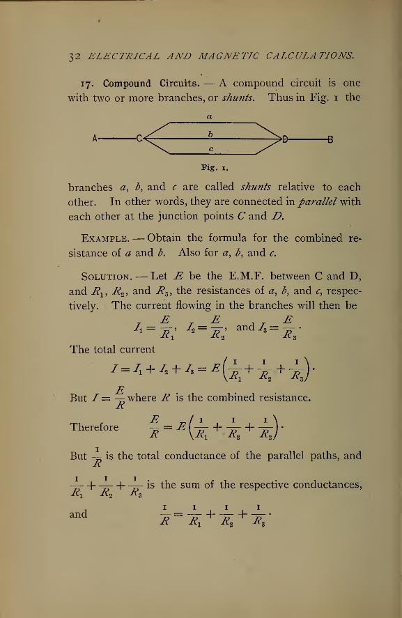
17. Compound Circuits. — A compound circuit is one
with two or more branches, or shunts. Thus in Fig. 1 the
a
Fig. 1.
branches a, b, and c are called shunts relative to each
other. In other words, they are connected in parallel with
each other at the junction points C and £>.
Example.— Obtain the formula for the combined re-
sistance of a and b. Also for a, b, and c.
Solution.— Let E be the E.M.F. between C and D,
and Rx , R2 , and Rg , the resistances of a, b, and c, respec-
tively. The current flowing in the branches will then be
^1= -£T> 72=-rr> and/>=—-•
The total current
/ = /1 + /, + /, = *(-L+-I- + -L).
But I= — where R is the combined resistance.R
Therefore f=£ (±- + ±- + ±-^
But — is the total conductance of the parallel paths, andR
— +— +— is the sum of the respective conductances,Rx R2 RB
and7?=~W + ~p~ + lp~
'
/C Kx
K%
K%
GENERAL LAWS OF RESISTANCE. 33
Hence, the total conductance of parallel circuits is the sum
of the individual conductances. Reducing to a common de-
nominator, equating the numerators, and solving for R,
we get
R^R2 = ^^2 + 1M?l f°r the first and second.
Then R (Rl + R2)= R,R2 .
From which R = f1^2
(17)Ri~t R2
Hence the resistance of two circuits in parallel, or shunts,
is equal to the product of the two separate resistances divided
by their su?n.
Also for all three paths,
R1R2R3= RR2R3 + RRlR 2 + RRXRZ .
Whence R (RXR2 + RX
R3 + R2R3) = R^R*.
Or in words, the combined resista?ice is equal to the product
of the separate resistances divided by the sum of their pro-
ducts taken two at a time.
In (18), if the resistances are equal to each other
7p 3 DR = —=r^ = — , or one-third of one resistance. Making
3 l 3
this rule general, if R1 represent each resistance and n the
number of such in parallel, then the combined resistance
will be
* = -< 09)n N 7
34 ELECTRICAL AND MAGNETIC CALCULATIONS.
Example.— Find the resistance of 10 incandescent
lamps in parallel, when the resistance of each, hot, is 200
ohms.
Solution.— Using (19), R = -2T°o°- = 20 ohms.
Example.— Calculate the resistance of 3 wires in
parallel, the resistances being, respectively, 5, 10, and 15
ohms.
Solution.— Applying (18),
5 X 10 x 15K = = 2.72 ohms.5 x 10 + 5 X 15 +10 X 15
18. Current Intensity in Compound Circuits.— Example.
—A current of 42 amperes flows in a circuit composed of
3 branches of 5, 10, and 20 ohms resistance, respectively.
Find the current intensity in each branch.
Solution.— From Ohm's law currents are manifestly
proportional inversely to resistances, and directly to con-
ductances. The conductances of the branches are,
respectively, \, y1^, 2V tota^ 2
7o> through which the total
current of 42 amperes flows. Therefore,
2V : 42 :: \ : x1 ; whence, xx= 24 amperes.
2~7q : 42 :: ^V : xi
%
->whence, x2 = 12 amperes.
2*0- : 42 : : %$ : xz ; whence, x3= 6 amperes.
19. Resistance and Drop of Potential. — According to
Ohm's law, E = IR, it is clear that potential difference, or
electromotive force, is directly proportional to the resis-
tance, the current remaining the same ; or, we obtain drop,
or difference of potential, between two points by multiplying
the resistance between the points by the current flowing
in the circuit.
GENERAL LAWS OF RESISTANCE. 35
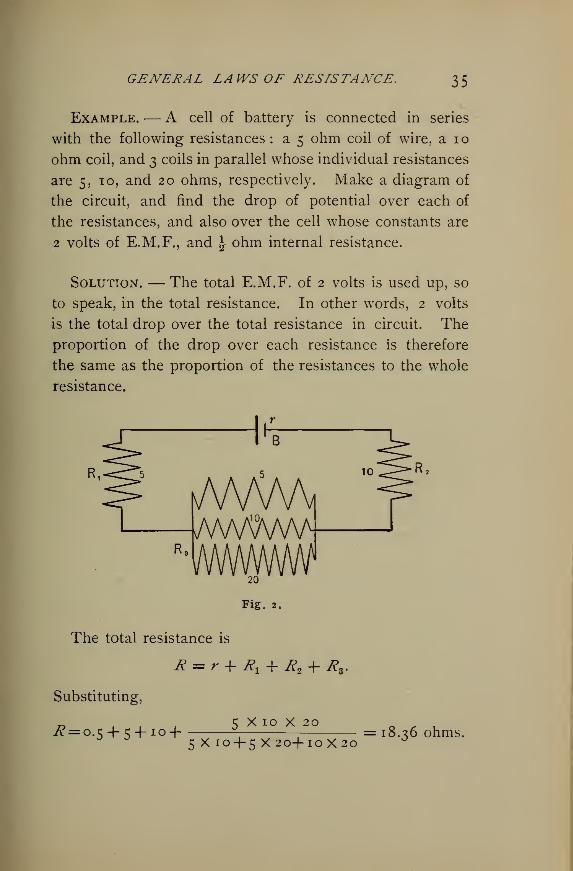
Example. — A cell of battery is connected in series
with the following resistances : a 5 ohm coil of wire, a 10
ohm coil, and 3 coils in parallel whose individual resistances
are 5,10, and 20 ohms, respectively. Make a diagram of
the circuit, and find the drop of potential over each of
the resistances, and also over the cell whose constants are
2 volts of E.M.F., and \ ohm internal resistance.
Solution. — The total E.M.F. of 2 volts is used up, so
to speak, in the total resistance. In other words, 2 volts
is the total drop over the total resistance in circuit. The
proportion of the drop over each resistance is therefore
the same as the proportion of the resistances to the whole
resistance.
B
kAAAAAMA/WW
20
Fig. 2.
The total resistance is
R = r + #! + R% + X*
Substituting,
r> ,5 x 10 x 20^= 0.5 + 5 + 10+ 5x10+ 5x20+10x20
= 18.36 ohms.
Therefore,
Ohms. Volts. Ohms. Volts.
18.36 : 2 :: 5 : #|_$
18.36 : 2 :: 10 • ^2?
18.36 : 2 :: o-5 : *;
18.36 : 2 :: 2.86 I X§\
36 ELECTRICAL AND MAGNETIC CALCULATIONS.
whence, xx= 0.544 volts,
whence, x2= 1.088 volts,
whence, x = 0.056 volts,
whence, xz = 0.312 volts.
A voltmeter applied to a cell when no circuit is con-
nected to it measures the total E.M.F. of the cell. But
if a circuit is at the same time attached to the cell the
voltmeter measures the total drop over the resistance of
the circuit. The difference between these two readings
of the voltmeter gives the drop over the internal resistance
of the cell under the given conditions. The same thing
is true of the dynamo.
Example.— What is the resistance of the battery
whose total E.M.F. is 91 volts, if, when it is connected in
series with three resistances of 6, 3, and 9 ohms, a volt-
meter connected across the 6 ohm coil reads 3 volts ?
Solution.— Making the proportions as above,
Ohms. Volts. Ohms. Volts.
6 : 3 : : 9 : xx ; whence, xx= 4J volts.
6 : 3 :: 3 : x2 \ whence, x2= 1 \ volts.
Total external drop = 3 + 4-^ + 1 2 = 9 volts. Therefore
the internal drop = 0.5 volt. Hence,
6 : 3 :: .# : 0.5 ; whence, x = 1 ohm, the in-
ternal resistance of the battery.
20. Original Problems.— 1 . A Bunsen cell has the
specific resistance of its inner and outer portions made
alike, each being 9 ohms per cubic centimeter. The
GENERAL LAWS OF RESISTANCE. 37
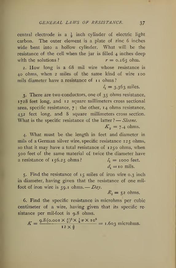
central electrode is a \ inch cylinder of electric light
carbon. The outer element is a plate of zinc 6 inches
wide bent into a hollow cylinder. What will be the
resistance of the cell when the jar is filled 4 inches deep
with the solutions ? r = 0.165 ohm.
2. How long is a 68 mil wire whose resistance is
40 ohms, when 2 miles of the same kind of wire 100
mils diameter have a resistance of 1 1 ohms ?
k = 3-3 63 miles -
3. There are two conductors, one of 35 ohms resistance,
1728 feet long, and 12 square millimeters cross sectional
area, specific resistance, 7 ; the other, 14 ohms resistance,
432 feet long, and 8 square millimeters cross section.
What is the specific resistance of the latter ?— Sloane.
K2 =7.4 ohms.
4. What must be the length in feet and diameter in
mils of a German silver wire, specific resistance 125 ohms,
so that it may have a total resistance of 1250 ohms, when
500 feet of the same material of twice the diameter have
a resistance of 156.25 ohms? lx = 1000 feet.
//x =io mils.
5. Find the resistance of 15 miles of iron wire 0.3 inch
in diameter, having given that the resistance of one mil-
foot of iron wire is 59.1 ohms.— Day.R2= 52 ohms.
6. Find the specific resistance in microhms per cubic
centimeter of a wire, having given that its specific re-
sistance per mil-foot is 9.8 ohms.
T 9.8(0.001 Xf)2 Xi7rX io6r . _K = -— ^— = 1.60^ microhms.
12x4
38 ELECTRICAL AND MAGNETIC CALCULATIONS.
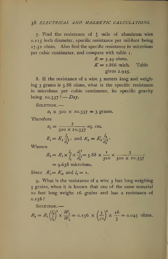
7. Find the resistance of \ mile of aluminum wire
0.1 15 inch diameter, specific resistance per mil-foot being
17.52 ohms. Also find the specific resistance in microhms
per cubic centimeter, and compare with table 1.
R = 3.49 ohms.
K= 2.866 mich. Table
gives 2.945.
8. If the resistance of a wire 3 meters long and weigh-
ing 3 grams is 5.88 ohms, what is the specific resistance
in microhms per cubic centimeter, its specific gravity-
being 20.337?— Day,
Solution.—ax x 3°° X 20.337 = 3 grams.
Therefore
ax= sq. cm.
300 X 20.337
1 2
Whenceley d? I 2
Ha= ^lXy2 X^-2=5.88 X—
X
k di 3°° 3°° X 20.337
= 9.638 microhms.
Since J x= K^ and /2 = 1.
9. What is the resistance of a wire 3 feet long weighing
5 grains, when it is known that one of the same material
10 feet long weighs 16 grains and has a resistance of
0.156?
Solution.—D /4V wx , / 3 V 16R* = ^1(7) x -jr^ = 0.156 X (— 1 X — = 0.045 ohms.
GENERAL LA WS OF RESLSTANCE. 39
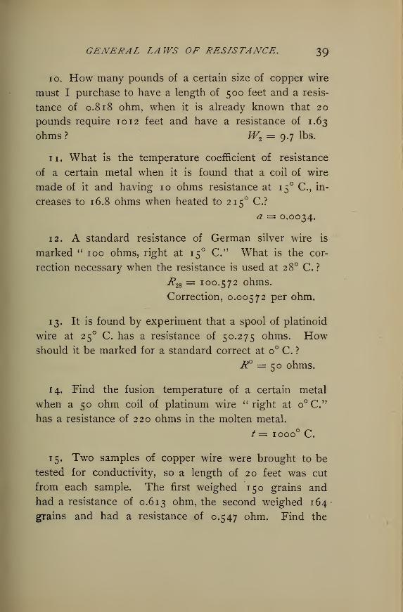
10. How many pounds of a certain size of copper wire
must I purchase to have a length of 500 feet and a resis-
tance of 0.818 ohm, when it is already known that 20
pounds require 1012 feet and have a resistance of 1.63
ohms ? W2= 9.7 lbs.
11. What is the temperature coefficient of resistance
of a certain metal when it is found that a coil of wire
made of it and having 10 ohms resistance at 15 C, in-
creases to 16.8 ohms when heated to 215 C?a = 0.0034.
12. A standard resistance of German silver wire is
marked " 100 ohms, right at 15 C." What is the cor-
rection necessary when the resistance is used at 2 8° C. ?
7?28 = 100.572 ohms.
Correction, 0.00572 per ohm.
13. It is found by experiment that a spool of platinoid
wire at 25 C. has a resistance of 50.275 ohms. Howshould it be marked for a standard correct at o° C. ?
R° = 50 ohms.
14. Find the fusion temperature of a certain metal
when a 50 ohm coil of platinum wire " right at o°C."
has a resistance of 220 ohms in the molten metal.
/= 1000 C.
15. Two samples of copper wire were brought to be
tested for conductivity, so a length of 20 feet was cut
from each sample. The first weighed 150 grains and
had a resistance of 0.613 ohm, the second weighed 164
grains and had a resistance of 0.547 ohm. Find the
40 ELECTRICAL AND MAGNETIC CALCULATIONS.
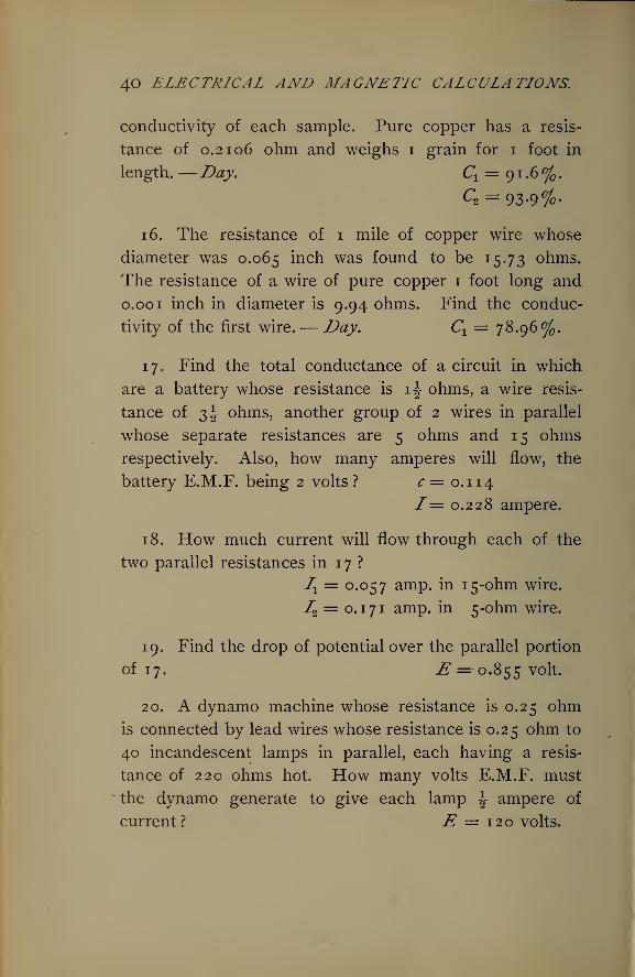
conductivity of each sample. Pure copper has a resis-
tance of 0.2106 ohm and weighs 1 grain for 1 foot in
length.—Day. Cx= 9 1 .6 °f .
C2 = 93-9%-
16. The resistance of 1 mile of copper wire whose
diameter was 0.065 mcn was found to be 15.73 ohms.
The resistance of a wire of pure copper 1 foot long and
0.00 1 inch in diameter is 9.94 ohms. Find the conduc-
tivity of the first wire.— Day. Ct= 78.96%.
17. Find the total conductance of a circuit in which
are a battery whose resistance is 4 ohms, a wire resis-
tance of 2>h ohms, another group of 2 wires in parallel
whose separate resistances are 5 ohms and 15 ohms
respectively. Also, how many amperes will flow, the
battery E.M.F. being 2 volts? c= 0.114
/ = 0.228 ampere.
18. How much current will flow through each of the
two parallel resistances in 17 ?
Ix = 0.057 amp. in 15-ohm wire.
I2 = 0.1 7 1 amp. in 5-ohm wire.
19. Find the drop of potential over the parallel portion
of 17. .£ = 0.855 volt.
20. A dynamo machine whose resistance is 0.25 ohmis connected by lead wires whose resistance is 0.25 ohm to
40 incandescent lamps in parallel, each having a resis-
tance of 220 ohms hot. How many volts E.M.F. must
the dynamo generate to give each lamp \ ampere of
current? E = 120 volts.
General laws of resistance. 41
21. When 4 wires of 2.5, 5, 10, and 20 ohms resis-
tance are joined in parallel, how much current will flow
in each when a battery whose E.M.F. is 19 volts and
whose internal resistance is 5 ohms is connected to
them ? I = 3 amperes.
I± = 1.6
72= 0.8
> amperes.73 = 0.4
74= 0.2 j
22. How many incandescent lamps, each requiring
1 ampere and having a resistance of 50 ohms, can be put
in parallel, or multiple, on a machine giving 60 volts and
having an internal resistance of 0.02 ohm, when the lead
wires have a resistance of 0.1 ohm ? n = 83 in parallel.
23. A dynamo giving 580 volts, having a resistance of
1 ohm, is connected to a circuit containing in parallel 80
groups of lamps, each group having 5 lamps in series
requiring \ ampere of current. Find the voltage between
the lines at the lamps, and also of each lamp. Also find
the resistance of the wires the drop of potential over
which is 40 volts, and find the percentage of the dynamo
power used in the lamps, and the percentage lost in the
machine itself. E = 500 volts for each group.
e =100 volts for each lamp.
R = 1 ohm in line.
Lamps get 86.2% of total power.
Internal loss 6.9% of total power.
Line loss 6.9% of total power.
24. A dynamo machine when not connected to any
circuit, but running under excitation at full speed, gives a
42 ELECTRICAL AND MAGNETIC CALCULATIONS.
pressure at the brushes of 120 volts, as measured by
a Weston voltmeter. When the full load of 60 lamps is
put on the machine, the voltmeter reads 113.8 volts while
the ammeter in the circuit reads 32 amperes. The volt-
meter is now taken to the center of the system of lamps
where it reads 109.5 volts. Find the drop on the line
and in the machine. Also find the resistance of the line,
of the lamps (average), and of the machine. Also
determine the ratio of external to total energy of the
machine. Internal drop = 6.2 volts.
Line drop = 4.3 volts.
Total drop = 10.5 volts.
Lamp E = 109.5 volts.
Resistance of machine = 0.194 ohm.
Resistance of line = 0.134 ohm.
Resistance of lamps = 205.2 (average).
Ratio of ex. to total energy = 94.8%.
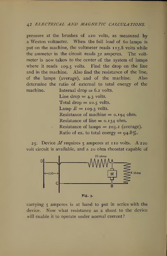
25. Device M requires 5 amperes at no volts. A 220
volt circuit is available, and a 20 ohm rheostat capable of
20 ohms" A
\j-
-2-20- M •X ohms
Fig. 3.
carrying 5 amperes is at hand to put in series with the
device. Now what resistance as a shunt to the device
will enable it to operate under normal current ?
GENERAL LA WS OF RESISTANCE. 43
Since between A and B only no volts are permissible,
there must be a drop in the 20 ohms of
220 — no = no volts.
Therefore the resistance in the circuit between A and Bis given by the proportion,
no volts : 2 o ohms : : no volts : x ; whence x = 2 o ohms.
But this is the combined resistance of circuit M and
shunt, and by (17)
^1 + ^2
Let JRX be the resistance of circuit M' = JLJA =22 ohms.
Therefore, substituting values,
22 ^2 .20 ==i~B"'
From which
7?2 = 220 ohms = shunt resistance.
The shunt will carry2ffi
— 5 = 0.5 ampere.
The same result may be accomplished by putting addi-
tional resistance in series. In this case, since the total
current is 5 amperes, the total resistance must be
220 -r- 5 =44 ohms.
This will require 44 — 20 = 24 ohms additional resistance
in series capable of carrying 5 amperes, and is much better.
26. Suppose a 500 volt street car line is called upon to
supply stationary motors in a factory requiring only 220
volts and 10 amperes of current. Suppose further that a
regulator rheostat of 18 ohms resistance can be put in
44 ELECTRICAL AND MAGNETIC CALCULATIONS.
series with the motors. What resistance now must be in
parallel with the motors ? Also what additional series
resistance would cause the motors to work normally ?
Shunt resistance = 39! ohms.
Series resistance =10 ohms.
The latter would be used in practice, if either.
ELECTRICAL ENERGY, 45
IV.
ELECTRICAL ENERGY.
21. Electrical and Mechanical Energy.— Energy, or the
capacity for doing work, is measured by the same units as
work. In the C.G.S. system, the unit is the erg, or the
work of 1 dyne of force acting through 1 centimeter of
space. In ordinary mechanical work, the unit is the foot-
pound, or the work of 1 pound of force acting through 1
foot of space. In all cases work and energy are expressed
by the product of force and distance. For estimating
activity, ox power, that is, the rate of doing work, the horse-
power equal to 33,000 foot-pounds per minute is used as the
unit. For some purposes also the kilogram-meter is used
as the unit of mechanical energy, being the work of 1 K.
acting through 1 m. of space. As a smaller unit the gram-
centimeter is chosen.
As the unit of electrical power the watt is used, and
for larger values the kilowatt is often convenient. The
capacity of dynamos is always expressed in the latter unit.
Expressing electrical power in watts by P, the formula is
P=EL (20)
Making the substitutions for E and I according to the
law of Ohm, P = I*j?^nAP=2 &.Jv
So that the formula for P can be used which is moat
convenient.
46 ELECTRICAL AND MAGNETIC CALCULATIONS.
It is sometimes necessary to make use of the whole
amount of electrical work in a certain time. Representing
the time in seconds by /, and the joules, or volt-coulombs,
by W, the rule for the whole number is,
W=EIt. (21)
Example.— Reduce to ergs the energy employed per
second by no volts of E.M.F. sending 10 amperes of
current through a circuit.
Solution.—1 volt = io8 C.G.S. units ; 1 ampere=io~1
.
Therefore 1 watt = io8 x io-1 = io7 ergs per second.
From (20),
P = £f= no X 10 = 1 100 watts.
1 100 watts X io7 = 11 X io9 ergs per second.
Example.— How many ergs of work will be done by
no volts and 5 amperes in half an hour ?
Solution.— *
W=EIt= no X 5 X 1800 X io7 = 99 X io11 ergs.
Example.— How many watts of electrical energy are
equivalent to 1 H.P. of mechanical energy.
Solution.—1 watt = io7 ergs; 1 H.P. = 550 ft.-lbs. per second.
1 m.= 3.28 feet; iK,= 2.2 lbs.; 1 K.-m. = 3.28 X 2.2
= 7.23 ft.-lbs.
Therefore
_ 55° _1 H.P. = ^— = 76.072 K.-m. per second.
7.23
= 76.072 x 1000 X 100
= 76.072 x iq5 gr.-cm. per second.
ELECTRICAL ENERGY. 47
The acceleration of gravity is approximately 980 cms.
per second, which is the ratio of the gravitation or practical
system of units to the C.G.S. system. Hence the value
given above is in C.G.S. units.
76.072 X io5 x 980 = 745.5056 X io7 dyne-cm., or ergs.
Therefore in round numbers
746 watts = 1 H.P. (22)
22. Electrical and Heat Energy.— No transformation of
energy can take place without more or less waste in the
form of heat, or unavailable energy. In every process of
producing electrical energy by transformation from me-
chanical or chemical energy, a considerable portion is lost
as heat in the generating device. Its transmission to the
points of utilization is also attended by much loss in heat-
ing the conductors. Again, whether motors are used for
power, or lamps for lighting, there is a still further trans-
formation into heat ; in fact, being necessary in the latter
in order to produce light. Hence it becomes very im-
portant to understand the exact relations of electricity
to heat energy.
It has already been shown that electrical power is rep-
resented by I2 R, — and EI. The heat into which this
power may be transformed is therefore directly porpor-
tional to these quantities.
Example. — Compare the heat produced in the con-
ductors in transmitting 50 amperes through a resistance of
1 o ohms with that when 2 o amperes are sent through the
same circuit.
48 ELECTRICAL AND MAGNETIC CALCULATIONS,
Solution.—Hx oo I*Rvand H2
oo 722 R2 . But Rx= R2 .
Hence 7^oo 502 x 10 = 25,000;
and Hi 00 202 X 10 = 4000.
Therefore § = 2-*^ = 6*.-£/2 4OOO
That is while the current in the first case is only 2\ times
that in the second, the heat produced is 65 times as great.
Therefore, the resistance remai?iing unchanged, the heat varies
as the square of the current.
Example.— How will the line loss in carrying 10
amperes through a 5 ohm circuit compare with that when
the circuit has only 2 ohms resistance ?
Solution.—Hx00 Ii
2Rv and H2 00 I£R2 - But 7[ = Iv
Hence Hxio2 X5 xH2 "T^^" 22 '
That is, Heat varies directly as the resistance when the cur-
rent is the same.
Example.— The voltage of the dynamo is 116, of the
lamps no, the line resistance is 10 ohms. How will the
line loss compare with the loss if the resistance were only
5 ohms, other conditions unchanged ?
Solution.— Line drop =116— 110 = 6 volts. Then
El (^
Hx ~RX 10 1
~H2- &?" 62 ""
2'
£2 5
ELECTRICAL ENERGY. 49
Example.— When the line drop is 5 volts and the cur-
rent 10 amperes, how much more heat is produced in
transmission than in a circuit carrying 10 amperes, and
having a drop of 2 volts ?
Solution.—LE, 10 X c = 2f times.
Hx __ IXEX _ 10X5
_H2 I2E2 10 x 2
To measure absolutely the amount of heat certain units
and constants are necessary. Joule* first found by experi-
ment that 772! foot-pounds of mechanical energy will
raise 1 pound ofwater i°Fahre?iheit, which he chose to call
a unit of heat; 772 is then "Joule's Equivalent," the
amount of mechanical work equivalent to 1 unit of heat.
This would be 1390.59 ft.-lbs. per degree C, or 423.85
kilogram-meters per kilogram-degree of heat. Later
experiments made in the U. S. give the value of the equiv-
alent as 427.52 K.-m. If the gram-degree of water is
used as the unit, 427.52 gram-meters are equivalent to
the small calorie. Representing the mechanical equiv-
alent byJ and reducing to ergs,
/= 427.52 x 100 x 980= 4.19 x io7 ergs.
1 calorie (water-gram-degree) = 4.19 x io7 ergs of work.
Example.— To find the ratio between joules of electri-
cal energy and calories of heat energy.
* British Association, 1843 ; also Phil. Mag., Vol. XXXII., 1843. See The Sec-
ond Law of Thermodynamics in Harpers' " Scientific Memoirs," p. 111.
t More recent researches fix this at 778 foot-pounds.
50 ELECTRICAL AND MAGNETIC CALCULATIONS.
Solution.—Ergs = watts x io7 = IE x io7 = io7 ergs in i watt,
i calorie = 4.19 x io7 ergs.
The ratio desired is then
watt io71 = 0.24.
calorie 4.19 x io7 4.19
Therefore, since the number of units is inversely as the
size of the unit the number of calories corresponding to
any number of watts, IE, will be
H (calories) = ZSx 0.24. (23)
To obtain calories multiply watts orjoules by 0.24.
The specific heat of a substance is the amount of heat
expressed in calories necessary to change the tempera-
ture of 1 gram of it i° C. Water is the standard and has
a specific heat of one.
Example.— Suppose no heat lost by radiation, how
hot will a copper conductor 1000 feet long and 0.25 inch
diameter and carrying iooo.amperes become in one sec-
ond ? In 1 o minutes ?
Solution.—R = K—„ = 9.8 ^ = 0.1568 ohm.d2 y
2502
The volume= 1000 x 12 x 0.25 x 0.7854= 589.04 cu. m.
The weight = 589.04 X 145.45 (wt. per cu. in.^85,675.9
grams.2
Zf = 1000 X 0.1568 X 0.24
= 37,632 calories per second.
Heat acquired by the wire= mass X sp. heat X / (rise).
jy = 85,675.9 X 0.0933 X /= 37>63 2 -
ELECTRICAL ENERGY. 5 I
Therefore / = r37? 32 = 4.7 above air.
8 5>6 75-9 X °-°933
In 10 min. this would be
4.7°X 600 = 2820 if possible.
Copper melts at 1050 C.
Although it is not known definitely because of so manyinfluencing conditions, yet approximately X oVo of a heat
unit is radiatedfrom each square centimeter of external sur-
face of a conductorfor each degree rise of temperature above
the air.
Example. — How hot will the conductor in the last
problem become, allowing the above rate of radiation to
take place ?
Solution.—Surface s of wire = (1000 X 12 x fXo.25 xf) X tt
= 5 8 >9°5 sq. cm.
Now the temperature will continue to rise until the rate
of radiation is equal to the rate of development of heat,
when it will remain stationary.
Rate of production of heat = I2R X 0.24 = iooo2X
0.157 X 0.24 = 37,680 calories per second.
Rate of radiation of heat =x-oVo" x 5 8 >9°5 x *>
in which / is the rise of temperature.
Therefore,
58,905 xt X ^roVo = 37>68o calories per second.
r™ c 37>68 ° X 4000 o r-Therefore /= — —— = 2CC2 C.58,905
M
This is sufficient to melt the wire.
52 ELECTRICAL AND MAGNETIC CALCULATIONS.
Example.— Making use of the principles already given,
find the diameter of a piece of copper fuse wire for the
protection of a street-car motor, in order to carry 40 am-
peres maximum current, the specific resistance of copper
per cubic centimeter being 1.6 16 microhms, and taking
its fusing point at 1000 C.
Solution.— Represent the diameter of the wire in
centimeters by d, and take 1 centimeter as the length for
purposes of the calculation, since the length does not
materially affect the point of fusion. The resistance of
this will be
1.616 X 1 1.616 X 4 ,R = —. -. = —-R
-9 ohms.
io6 X Id2 X-J
From (23)
rr „ n 9 1.616 X 4 1H = I2R X 0.24 = 402 X —e -~ X 0.24 cal.IO X 7TU
This is the heat developed per second in the fuse-wire.
For the purposes of protection, the rate of radiation must
not become equal to this till the temperature of fusion is
reached, or 1000 C. The heat radiated per second at
1000 C. is, for 1 cm. length,
H = X ltd X 1000 .
4000Therefore
1 ,—2 1.616 X 4
X 7rd X 1000 = 40 X. £— -^X 0.24.4000 *io6 X 7rd2
From which,_ —2 1.616 X 4 4°°°d* = 40 X s ^ X 0.24 X
IO6 X 7T2 IOOO
ELECTRICAL ENERGY. 53
Hence —2 , ,,, 40 x 1.010 X 0.000391a* = ^- = 0.0010196.
1000Therefore
3,
d= V0.0010196 = 0.1 cm. = 40 mils = No. 18.
It will be clear that the final expression for d 3 just
above may be written so as to make a general rule ; for
40 = I2, 1.6 1 6 = K, and 1000 = /. Therefore the for-
mula for general application is
3 _ I2 X K X 0.000391(2 4)
From the foregoing principles tables of " safe carrying
capacity " are worked out. Some allow higher tempera-
tures as " safe " than others. From experiment and cal-
culation Dr. A. E. Kennelly has arranged a table of
carrying capacities, now generally accepted, which are
about 20 per cent lower than those of the National Code.
It can also be seen from what precedes that the heat
increases with I2 and with -— • Henced z
I 2
Now 30 C. above the surrounding air is at least a safe
limit, though some would allow higher temperatures. In
order that this temperature be not exceeded, the following
empirical formula may be used for finding 7", the safe
current for a wire of a given diameter d;
2500* A convenient practical formula for resistance due to any temperature t is
*<==__9.6 (1 + .004 1) 1
t- d*
54 ELECTRICAL AND MAGNETIC CALCULATIONS.
23. Efficiency of Transformation and Transmission of
Energy.— The efficiency of conversion of an electrical
generator is the ratio of the total electrical energy gen-
erated to the mechanical energy supplied to the machine.
Representing the efficiency of conversion by C,
E.H.P. (total)C =
M.H.P.' (26)
The commercial efficiency of a generator is the ratio of
the electrical energy supplied to the external circuit to
the mechanical energy used in driving the machine.
ThereforeE.H.P. (external)
C°m-
Eff'
=ALHJ\ ' (27)
The electrical efficiency of a generator is the ratio of the
external electrical energy to the total electrical energy
developed in the armature of the machine. Hence,
Elec. Eff. = E^ p(e
f6r"al)
• (28)E.H.P. (total)
v '
Station efficiency is often employed to designate the
ratio of the power delivered to the line terminals on the
switchboard to the power supplied to the engine by the
steam. The difference between these two quantities is
the total loss in the station beginning at the engine.
Plant efficiency may also be used to represent the ratio
of the energy delivered to the lamp or motor terminals to
the energy supplied to the steam engine. The latter is
important in judging of the performance of the whole
system and in fixing charges to consumers.
The various losses in a plant are friction and radiation
losses in the engine ; losses in belting and so forth ; fric-
ELECTRICAL ENERGY. 55
tion, hysteresis, eddy current, and I2R losses in dynamos,
and I 2R losses in the switchboard connections and in the
line. Evidently that plant will be most efficient which
has observed the means of reducing each of these losses
to the lowest possible.
Example.— What is the commercial efficiency of a
dynamo, when a dynamometer shows that it absorbs
8 H.P. of mechanical energy while furnishing 92 incan-
descent lamps with 46 amperes of current at 115 volts ?
Solution.— E.H.P. = II5 * 46 = 7.746
Com. Eff. = -|- = 87.5%.
Example.— The resistance of an armature is 0.02 ohmand the shunt fields have a resistance of 25 ohms. The
generator absorbs 10 H.P. and delivers 50 amperes to the
line, while the brush E.M.F. is 118.8 volts. What is
the efficiency of conversion, commercial efficiency, and the
electrical efficiency of the machine? Also the per cent
of loss in field magnets and armature ?
Solution.— External watts = 118.8 x 50 = 5940.
1 18.8rield current = = 4.75 amperes;
o
Field watts = 118.8 x 4.75 = 564.3.
Armature watts loss = 54-75 X 0.02 = 60,
Therefore
Total watts = 5940 + 564.3 + 60 = 6564.30
10 H.P. = 7460 watts supplied.
56 ELECTRICAL AND MAGNETIC CALCULATIONS.
HenceEff. Con., C = 6564.3 -T- 7460 = 87.99%.
Com. Eff. = 5940 -r- 7460 = 79.62%.
Elec. Eff. = 5940 -T- 6564.3 = 90.48%.
Total machine loss = 60 + 564.3 = 624.3 watts.
Electric loss = 624.3 "*" 6564.3 = 9.51%.
These figures would show a very badly designed machine
for modern times.
Example.— Calculate the efficiency of a long distance
line when 50 amperes at 3600 volts are supplied to it, its
resistance being 10.8 ohms.
Solution. — Watts supplied = 3600 x 50= 180,000.
Line loss = 50 X 10.8 = 27,000 watts.
Therefore,
Watts delivered = 180,000 — 27,000 = 153,000.
Hence Line eff. =^|^ = 85 %,and Line loss = ffififr = 15%.
Example.— A plant consists of a generator of 94%efficiency, step-up transformer (lower to higher voltage)
96% efficiency, line 90% efficiency, lowering or step-down
transformer 95%. The engine that drives the dynamo
has an efficiency of %%°/ - If 339-3 2 K-w - of energy is
delivered at secondaries of step-down transformers, cal-
culate the plant efficiency and the H.P. supplied to the
engine ; also the station efficiency.
Solution.— Let 100% = energy supplied to engine,
0.88 x 0.94 X 0.96 X 0.90 X 0.95 = 67.89% = plant effi-
ciency.
ELECTRICAL ENERGY. 57
Therefore
67-89% = 339-3 2 K -w -
i%=5-100% =500 K.W. supplied to engine.
H.P. of engine = ^Vf— = 67°-
The station efficiency = 88% of 94% = 82.72%, if weinclude the belt losses and slipping losses in the 12% en-
gine loss.
The efficiency of most machinery is much higher at full
load than at very small loads. This is largely true of en-
gines, transformers, dynamos, and motors. However, in
the latter the difference between full-load efficiency and
say one-half load is small. The efficiencies as previ-
ously given are for full load. In engines the losses are
almost constant for all loads. Hence an engine which at
full load would have an efficiency, say of 90%, at half
load would have only about 82^ efficiency. To illus-
trate, take 100 H.P. supplied, 90 H.P. delivered, making
10 H.P. lost. Half load delivers 45 H.P., requiring 45 +10 = 55 to be supplied. Efficiency = f4 = 82 °/ . There-
fore all engines should keep loaded as fully as possible.
For dynamos, motors, and large transformers, the effi-
ciency changes but little with change of load, if the
load is not allowed to fall below about one-half.
Example.— A street car with its load weighs 10 tons,
and the average grade of the street is 5%. Allowing an
efficiency for the motors and gearing of 75%, and a hori-
zontal speed of 10 miles an hour, what power must be
applied to the motor ?
58 ELECTRICAL AND MAGNETIC CALCULATIONS.
Solution.— The horizontal effort may be taken as 25
lbs. per ton, making 10X25 = 250 lbs. for this car.
Work done horizontally per minute is then
TT _ 5280 X 10 X 250 _ „W1= - — = 220,000 ft.-lbs.
60
The vertical lift per minute is
5% of 5280 X 10 ,^ ^ = 44 ft. per mm.DO
Work done vertically per minute is therefore
JV2 = 10 X 2000 x 44 = 880,000 ft.-lbs.
Total work required at the wheels of car
= 220,000 + 880,000 = 1,100,000 ft.-lbs.
Horse-power necessary to be taken from the line is
1,100,000 TT _-*- 33,000 = 44.4 H.P.
0-7S
Example.— What efficiency will be necessary in a sta-
tionary motor in order that it may develop 450 volts coun-
ter E.M.F. when the applied E.M.F. is 500 volts?
Solution.— Since the output is the product of the cur-
rent and the counter E.M.F., or IE2J and the intake is the
product of the current and the applied E.M.F., or IEV the
efficiency is,
TE2 E2 450 ^
Example.— Determine at what efficiency a motor
gives its greatest output per minute.
ELECTRICAL ENERGY. 59
Solution. — Since the current through a motor is
in which E1and E2 are the applied and counter
Et— E2
RE.M.F's. respectively, and R is its resistance, the output is
77 (77 - 77 \
E2I = ——
—
x— — • In this E1 and R are constants.RObviously, then, the numerator, consisting of this product
of a variable and the difference between a constant and
the variable, will be the greatest whenE2= \E
X . In other
words, the output is at the greatest rate when the counter
E.M.F. is \ the applied E.M.F., and the efficiency, there-
fore, 50%. To illustrate,
Suppose the applied E.M.F., E1= 100 volts.
Suppose the counter E.M.F., E2= 50 volts.
Then the output will be represented by
E2 (Ex- E2) = 50 (100 - 50) = 2500.
Let the speed increase, so that the counter E2= 60 volts.
The output is now
60 (100 — 60) = 2400.
Again, let a decrease of speed reduce the counter
E.M.F., E2 , to 40 volts. Then the output is
40 (100— 40) = 2400.
This shows that the greatest rate of work is done at an
efficiency of 50 per cent, but is modified in practice.
24. Original Problems.— 1. A voltmeter connected
across a Buckeye lamp read 109.5 Y0 ^ts when 0.6 amperewas flowing through the lamp. How many joules of
energy are used by the lamp per second, and how many
60 ELECTRICAL AND MAGNETIC CALCULATIONS.
ergs ? How many such lamps can be maintained per
H.P. ? How many calories of heat are developed per
second in each lamp? If the lamp has a candle-power of
14, what is the efficiency in watts per c.p. ?
JV= 65.7 joules= 657,000,000 ergs= 15.7 cal.
Eff. = 4.7 watts per c.p.
1 1 lamps per H.P.
2. I wish to supply 50 lamps at no volts, resistance of
each being 220 ohms hot. The line loss is 5 °j , the com-
mercial efficiency of the generator can be counted as 92 %,and the engine and belt losses are 15%; what I.H.P.
will be necessary to operate the plant ?
I.H.P. = 5 (strictly 4.9).
3. Find the H.P. required to furnish 40 arc lamps in
series with 7 amperes of current, the resistance of each
lamp being 8 ohms, line 25 ohms. How many watts are
necessary per lamp? Assuming a normal candle-power
of 1200 for each lamp, find the efficiency in watts per c.p.
Compare last result with the efficiency in 1.
H.P. = 22.6.
Eff. = 0.326 watt per c.p.
4. An engine on full load indicates 12.5 H.P. Assum-
ing engine and belt losses to be 12%, and the commer-
cial efficiency of the dynamo 90%, line loss 5%, how
many no volt incandescent lamps constitute the load?
Also, what is the voltage at the brushes ? How many in-
candescent arcs could be supplied at 4 amperes each ?
No. lamps, n = 127.
Brush volts = 115.8.
Inc, arcs, n = 16.
ELECTRICAL ENERGY. 6
1
5. The resistance of a certain dynamo machine's arma-
ture is 0.016 ohm, that of the external circuit 0.757 ohm.
The power required to operate the machine is 7.604 H.P.,
and the current produced is 83.7 amperes. What are the
efficiency of conversion and the commercial efficiency of
the machine ? C = 95.5 °/ .
Com. Eff. = 93.5%.
6. A circuit consists of 100 incandescent lamps
arranged in 20 parallel groups, each group containing 5
lamps in series. The voltage between the main wires at
the center of the lamp system is 550, and the resistance
of each lamp is 212 ohms, average. Find the watts and
ergs used per lamp. Also the amount of current flowing,
and the efficiency of transmission if the line resistance is
8 ohms.
Watts per lamp = 57 = 57 x io7 ergs per sec.
Eff. of trans. = 87%./= 10.37 amperes.
7. If the following set of conditions are representative,
how many no volt incandescent lamps can be supplied
per I.H.P. of the engine ? Lamps 100, drop in line
6.5 volts, resistance of fields, shunt wound, 25 ohms, of
armature 0.025 onm3 ^ or generator 96%, engine and
belt losses 15% ? Find the plant efficiency.
Lamps per I.H.P. = 9.
Plant eff. = 73%-
8. Compare the external heat with the internal in the
following cases ; also determine the efficiency in each
case ; the battery resistance is equal to 7 feet of a certain
size of wire, and for the first case has its terminals con-
2 ^= 22.2%
62 ELECTRICAL AND MAGNETIC CALCULATIONS.
nected through 2 feet of the wire ; for the second case
the battery terminals are connected through 53 feet of
the wire., N Zf (ex.) 2 „
^w^rr eff -=
2 +7
V' -^(m.) 7 53+7
6/
9. A current of 0.75 ampere is sent for 5 minutes
through a column of mercury whose resistance is 0.47
ohm, and which weighs 20.25 grams, and has a specific
heat of 0.0332. Find the rise of temperature, assuming
no heat lost by radiation. — Day. t = 28 C.
10. Assuming the rate of radiation previously given,
find how hot an iron wire \ inch in diameter and 100
feet long will become in the air when it carries 20 am-
peres. / = 47 .
11. What must be the diameter of a German silver
wire 50 feet long to carry 5 amperes so that it may not
rise to exceed 30 above the temperature of the sur-
rounding air? d = 74 mils = No. 13.
12. How many amperes of current may a copper wire
64 mils diameter and 500 feet long carry so as not to
exceed 25 above the temperature of the air ?
/= 13 amperes.
13. A coil of platinum wire is immersed in a tank
holding 3 quarts of water which is constantly stirred
while 4 amperes of current pass through the wire which
has a length of 20 feet, and diameter of 40 mils. The
initial temperature of the water is 15 . Assuming no
loss by radiation, what will be the temperature of the
water after 10 minutes? /= 15.56° C.
ELECTRICAL ENERGY. 63
14. Find the gauge of a zinc wire to be inserted in a
circuit to carry 250 amperes as a maximum current, when
zinc fuses at 422 C. d = 270 mils = No. 2.
15. What size of copper wire must be used for the
protecting fuse of a circuit designed to carry normally
300 amperes, allowing temporary over-loading of 40% ?
d = 0.48 cm. = 188 mils = No. 5.
16. What is the fusion temperature of an alloy when
a piece of gauge number 16 fuses at 20 amperes, know-
ing that the specific resistance is 24.66 ?
/= 1800 C.
17. If a certain machine when run at 2200 r.p.m.
generates 116 volts at the brushes, and supplies no volts
and 22 amperes of current at a certain distance, how
many times as far will it furnish the same power when
run at 2300 r.p.m. ? 1.9 times as far.
18. The poles of a dynamo whose resistance is 0.08
ohm are in the first place joined through 4 incandescent
lamps in series, in the second place through 4 in parallel.
The resistance of each lamp is 50 ohms, and the
mechanical energy supplied to the machine is the same
in both cases. Compare the amounts of heat developed
in the machine ?— Day. The lamp resistance is here
wrongly assumed constant. H2 16
j2i~T"19. A circuit contains 20 incandescent 220 ohm lamps
in parallel, the lead wires having a resistance of 1 ohmand the machine 0.1 ohm. Now a wire whose resistance
is 0.5 ohm is connected across the leads at the lamps,
64 ELECTRICAL AND MAGNETIC CALCULATIONS.
while the E.M.F. at the brushes is 120. Compare the
current in the lamps with that in the wire. How does
the heat in the machine compare in each case with that
in the external circuit ? How much greater load is
placed on the engine by the wire ?
Normal /= 10 amperes.
With wire, /= 81 amperes, 3.5 in lamps.
Normal heat in machine Hx= 10 watts.
2d heat in machine H2= 656 watts.
Load with wire 8 times normal.
20. A dynamo and a motor are exactly alike, each
having a normal E.M.F. of no volts when running at
2000 r.p.m. The dynamo is kept running at the normal
speed, but the load of the motor is such that it runs at
1500 revolutions per minute. What must be its efficiency
at this load and speed ?
Counter E.M.F = 82.5 volts.
Eff. = 75%.
21. What H.P. must a hoisting motor be capable of
developing when 900 pounds are to be lifted 80 feet per
minute, the cage being counterbalanced by a weight
suspended from the drum, and making an allowance of
50% of its power for losses due to friction in all parts ?
H.P. = 4.37.
22. What H.P. would be required if the cage were
drawn at the same speed up an incline in which there is
a rise of 10 feet for every 10 feet in a horizontal direction,
in other words when the grade is 100% ?
ELECTRICAL ENERGY. 65
Solution.— Here the ratio of the vertical lift to the
slope must be taken as the ratio of power required to
that for a vertical lift. Slope = Vio2 + io2 = 14.14.
Therefore the power will be 4.37 X = x H.P.14.14
23. A motor is to operate a pump lifting 20,000 gallons
per hour 500 feet high. Allowing an efficiency of 60%in the pumping system, and given that 1 gallon weighs
8.33 lbs., how many H.P. must the motor develop ?
Also putting its efficiency at 90% and operating it on a
220 volt circuit, how many amperes of current will it
require? 70 = H.P. developed.
78 = H.P. supplied.
/= 265 amperes.
24. An electric car with its load weighs 12 tons and is
to maintain a speed of 10 miles an hour on a grade of
2%; that is, 2 feet rise for every 100 measured hori-
zontally. Allowing a traction effort of 25 lbs. per ton,
how much power is necessary at the axles, and assuming
an efficiency of 75% in motor and gearing, how manyamperes will it take from a 500 volt circuit ?
Power at axles = 21 H.P.
/= 41.8 amperes.
66 ELECTRICAL AND MAGNETIC CALCULATIONS.
WIRING FOR LIGHT AND POWER.
25. Drop of Potential and Size of Leads.— The simplest
case of wiring is that for arc lamps which are all in series,
70 to 80 volts being required for each lamp. The ma-
chine at the station automatically changes the pressure to
suit the number of lamps, while the current is kept con-
stant at 5 to 7 amperes, depending on the system used.
This is therefore a constant current system.
The resistance of the wire is generally taken so that
not to exceed 10% of the dynamo volts will be required
to pass the current through it.
Example.— A certain circuit carries 40 T.H. arc lamps
in series, inclosed type ; each lamp requires 75 volts, the
current being 5.5 amperes. Allowing a line drop of 5%what must be the difference of potential at the brushes,
and what size of wire must be used, its length being
3 miles ?
E = 3157.8 volts.
R = 28.69 ohms.
Wire is No. 12, A.W.G. or B. & S.
Incandescent arc lamps are those designed to work in
parallel on the same circuit as incandescent lamps. They
are used for both interior and exterior lighting, and wound
for no or 50 volts. The calculations are the same in
WIRING FOR LIGHT AND POWER. 6
J
this case as for incandescent work, and so will not be
treated separately.
Although for incandescent lighting and power on the
parallel, or constant potential system, the wiring often
becomes complex and the exact distribution of copper in
the various parts of the net-work a matter for much study,
yet the principles which govern the calculations are the
same as for simple circuits, and are all based on Ohm's
law. The problem may be to calculate the leads and
lamp circuits leading from street mains or transformers to
the lamps, or it may include the mains and all the wiring
of a complex system.
Example.— The street mains are kept at the constant
potential of 116 volts. Lamp leads are run out to the
center of a system of 150 incandescent lamps. The volt-
age at the point from which the lamp circuits leave the
leads is 112. Calculate the resistance per foot of the
wire to be used if the leads are 100 feet long, and obtain
from the table the corresponding gauge number.
Solution.— Line drop = 116—112 = 4 volts.
/for 150 lamps = 150 X \ = 75 amperes.
E 4Hence R, from Ohm's law, = — = — = 0.0a ohm.^ 75
M
Leads contain 200 feet of wire ; hence the resistance per
foot of the wire to be used is
R = 0.053 -T- 200 = 0.000266 ohm ; and per 1000 feet,
R = 0.000266 X 1000 = 0.266. From the table this
corresponds to No. 4 A.W.G.
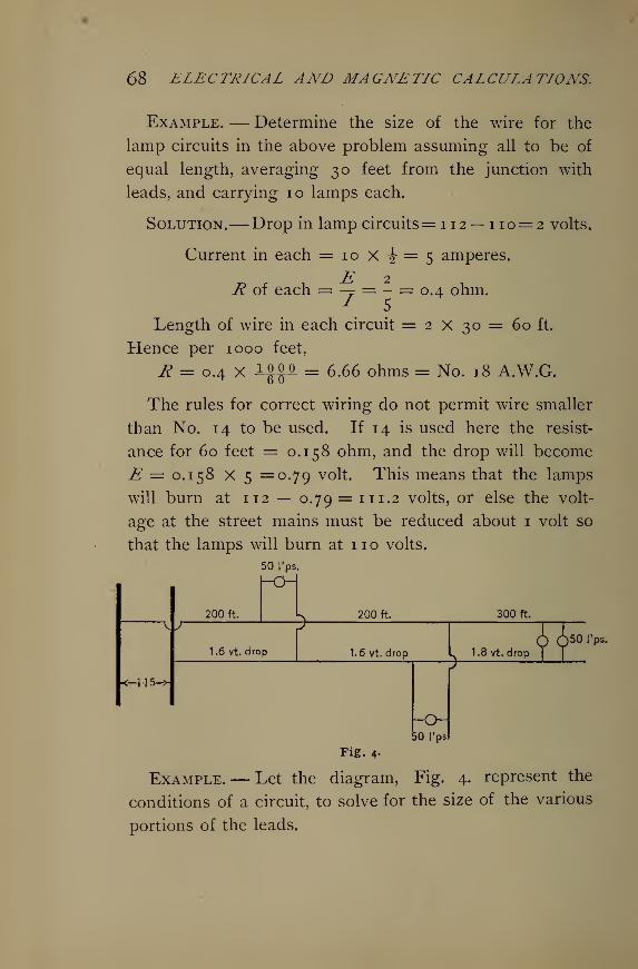
68 ELECTRICAL AND MAGNETIC CALCULATIONS.
Example. — Determine the size of the wire for the
lamp circuits in the above problem assuming all to be of
equal length, averaging 30 feet from the junction with
leads, and carrying 10 lamps each.
Solution.— Drop in lamp circuits=112 — 110= 2 volts.
Current in each = 10 X -J-= 5 amperes.
0.4 ohm.R of each = — = -1 5
Length of wire in each circuit = 2 x 30 = 60 ft.
Hence per 1000 feet,
R = 0.4 X 10 00. _ 6.66 ohms = No. 18 A.W.G.
The rules for correct wiring do not permit wire smaller
than No. 14 to be used. If 14 is used here the resist-
ance for 60 feet = 0.158 ohm, and the drop will become
E = 0.158 X 5 =0.79 volt. This means that the lamps
will burn at 112 — 0.79 = 111.2 volts, or else the volt-
age at the street mains must be reduced about 1 volt so
that the lamps will burn at no volts.
50 I'ps.
\f
<—H-5->
200 ft. 200 ft. 300 ft.
1.6 vt. drop 1.6 vt. drop a50 I'ps.
_
50 I'ps
Fig. 4-
Example.— Let the diagram, Fig. 4. represent the
conditions of a circuit, to solve for the size of the various
portions of the leads.
WIRING FOR LIGHT AND POWER. 69
Solution.— The current required by the first group
of 50 lamps, each of which has a resistance of 220 ohms,
will be
t I][ 5— x -6
Jx = —— = 2C.7 amperes.1 220 -r- 50D
'*
__ , T 11^.4 — 1.6The second, A = — = 2 s. 41 amperes.2 220-5-50 D ^ v
m. . . , ^ 1 1 1.8 — 1.8The third, A = = 2 c amperes.
220-^50 ° r
Therefore the total current flowing through the first
section of the leads is
I' =25.7 + 25.41 + 25 = 76.1 amperes.
Total current flowing through the second,
I" = 25.41 + 25 = 50.41 amperes.
In the last section,
I,n = 25 amperes,
Hence the resistance of the first section is
j?E I -6
i.R, = — = —— = 0.021 ohm.I 76.1
This is for 200 X 2 = 400 feet of wire.
The resistance for 1000 feet then is
_ 0.021 X 1000,R = = 0.0C2 ohm.
400 °
Table No. 2 gives this to be about No. 000 wire.
The resistance of the second section is
Ro = —-— = 0.0317 ohm for 400 feet.250-41
6'
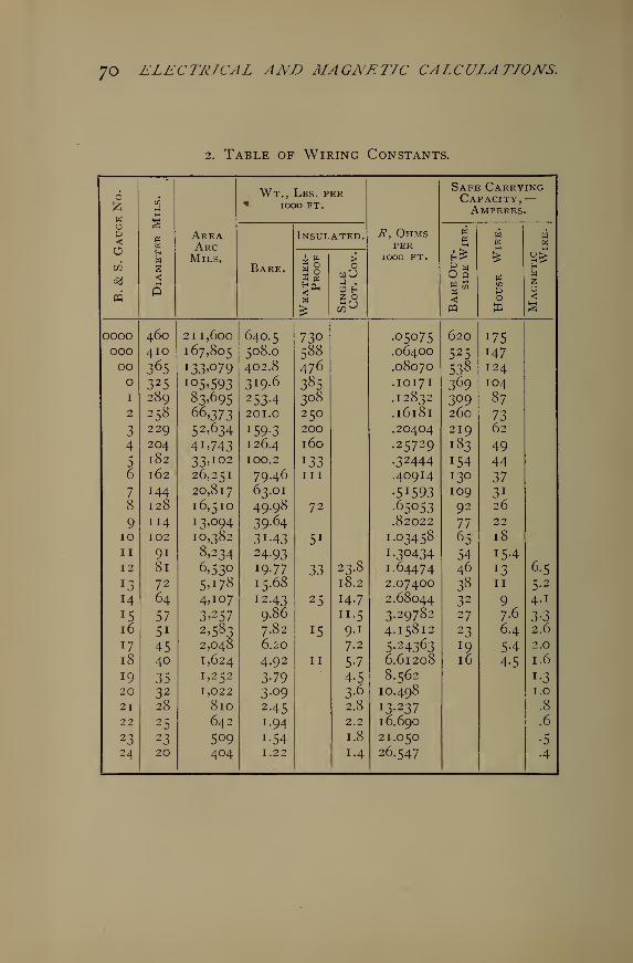
7o ELECTRICAL AND MAGNETIC CALCULATIONS.
2. Table of Wiring Constants.
6 Wt., Lbs. perSafe CarryingCapacity.—
wop
J
Area
< IOOO FT.
7?, Ohms
A MPERES.
Insulated. H04
w wWHW
ArcMils.
perIOOO FT. &
64 P4
1 br.
04 £ s>
n
Bare. §8X 04
w
a .
Hfc
win
p
H
<5
*£U pq H §
oooo 460 2II,6oo 640.5 730 •05075 620 175000 410 167,805 508.O 588 .064OO 525 147oo 365 I33»079 402.8 476 .08070 538 124o 325 !05>593 319.6 385 .IOI7I 369 104i 289 83>695 2534 308 .12832 309 872 258 66,373 201.0 250 .16181 260 73
3 229 52*634 J 59-3 200 .20404 219 62
4 204 4i*743 126.4 l6o .25729 183 495 182 33* 102 100.2 *33 .32444 154 446 162 26,251 79.46 in .40914 130 377 144 20,817 63.01 •5 X 593 109 3i
8 128 16,510 49.98 72 .65053 92 26
9 114 13,094 39-64 .82022 77 22
10 102 10,382 31.43 5 1 1.03458 65 18
ii 91 8,234 24.93 1.30434 54 15412 81 6*53° 19-77 33 23.8 1.64474 46 x 3 6-5
13 72 5*i78 15.68 18.2 2.07400 38 11 5-2
14 64 4,107 12.43 25 14.7 2.68044 32 9^ 4.1
15 57 3*257 9.86 11.5 3.29782 27 7.6 H16 5i 2*583 7.82 iS 9-i 4-15812 23 6.4 2.6
17 45 2,048 6.20 7.2 5-24363 J 9 54 2.0
18 40 1,624 4.92 11 5-7 6.61208 16 4-5 1.6
19 35 1,252 3-79 4-5 8.562 1320 32 1,022 3-09 3^ 10.498 1.0
21 28 810 2.45 2.8 13.237 .8
22 25 642 1.94 2.2 16.690 .6
23 23 509 1.54 1.8 21.050 •5
24 20 404 1.22 1.4 26.547 4
WIRING FOR LIGHT AND POWER. 7
1
Per 1000 ft.,
n 0.0317 X 1000 . XTR = ——- = 0.079 ohm, or No. 00 wire.400
The resistance of the third section is
1 8R s = — = 0.072 ohm for 600 feet.
2 5
Per 1000 ft.,
_ 0.072 X 1000 , ATR = —I = 0.120 ohm, or No. 1 wire.600
The practice in wiring is so to distribute the drop of
potential, by adjusting the resistance of the circuits, that
it decreases from the dynamo outwards to the lamps.
For example, let a small plant supply a circuit so as to
lose 6 volts. We may wire for 3 volts drop in the mains,
2 volts in the leads, and 1 volt in the lamp circuits.
26. Wiring Formulae and Diagrams. — For greater con-
venience in calculation we may apply a certain formula
for finding the number of circular mils required in a
wire to supply a given number of lamps, at any distance
required, for a given drop of potential.
Example.— Let it be required to derive the formula
for the circular mils required in any portion of a circuit
when the distance and the number of lamps and per cent
of drop are given.
Solution.— We have already for resistance (.15),
R = kL = io . 79J_.
However, 10.79 *s nere used as more nearly represent-
ing the specific resistance of ordinary commercial copper
72 ELECTRICAL AND MAGNETIC CALCULATIONS.
than 9.8, the specific resistance of pure copper which was
used previously in this book. By transposition of the
above formula we have for circular mils,
We also have for the resistance of any number of lamps
n in parallel when the resistance of each one is r,
r (hot)'!=—"Z. (30)
Since resistances are proportional to the drops of
E.M.F. in them,
R (line)°f
drop in line .
r1 (lamps)""
100 — % *^3^
Here 100—°f
drop in line = per cent drop in lamps.
The per cent is calculated on the highest voltage of the
system as a base. By transposition of (31),
* =^4- (33)IOO - % w '
Putting in (32) the value of rx from (30),
^ = ^(hot)x _% (33)n 100 — °j
Equation (33) gives the line resistance in terms of the
resistance of one lamp hot, the number of lamps, and
the per cent drop. Having thus the resistance and
knowing the length of the wire, the size could be deter-
mined as we have already done. But to make the work
still more complete, place this value of R in (29) ; then
for circular mils we have
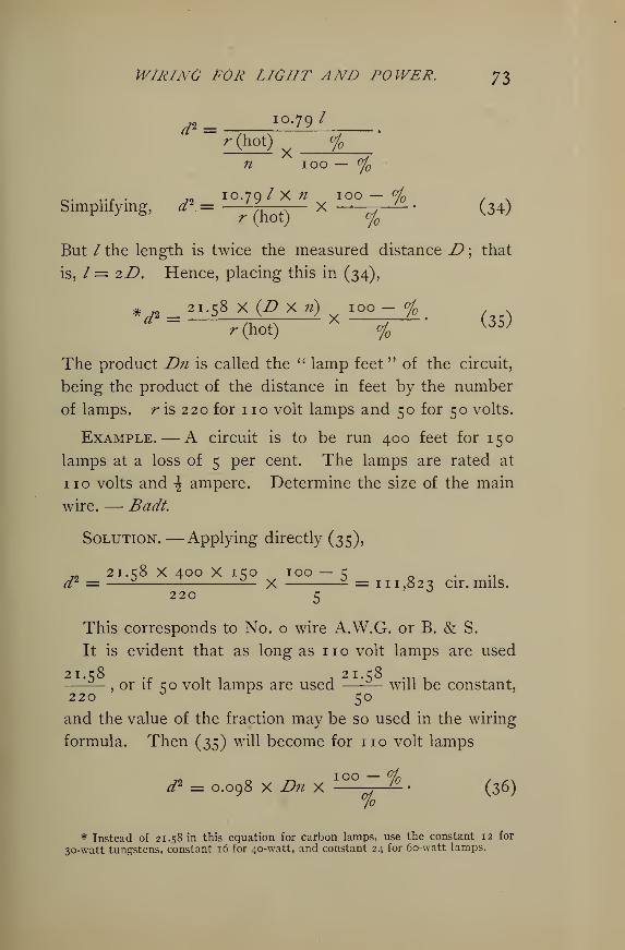
WIRING FOR LIGHT AND POWER. J$
d* = IO -79/'•(hot) %
n ioo —°f
o- rr • ^2 IO.79/ X^2 IOO — % /Simplifying, * _«j__ x—
^
(34)
But / the length is twice the measured distance D ; that
is, / = 2D. Hence, placing this in (34),
# 21.58 x {Dy.fi) 100- %
The product Dn is called the " lamp feet " of the circuit,
being the product of the distance in feet by the number
of lamps, r is 220 for no volt lamps and 50 for 50 volts.
Example.— A circuit is to be run 400 feet for 150
lamps at a loss of 5 per cent. The lamps are rated at
no volts and \ ampere. Determine the size of the main
wire. — Badt.
Solution.— Applying directly (35),
.. 21.58 X 400 X 150 100 — 5 • .1
d2 =— — X - = 111,823 cir. mils.220 5
J
This corresponds to No. o wire A.W.G. or B. & S.
It is evident that as long as 1 1 o volt lamps are used
21. c8 tit 1 21. c8 .„ .—^—, or if co volt lamps are used —^— will be constant,
220 ° r50
and the value of the fraction may be so used in the wiring
formula. Then (35) will become for no volt lamps
d2 = 0.098 X Dn XIO° ~ ^
- (36)%
* Instead of 21.58 m this equation for carbon lamps, use the constant 12 for
30-watt tungstens, constant 16 for 40-watt, and constant 24 for 60-watt lamps.
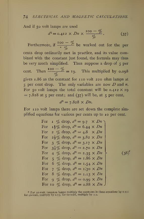
74 ELECTRICAL AND MAGNETIC CALCULATIONS.
And if 50 volt lamps are used
</2 = 0.412 x Dn X
100 %%
(37)
Furthermore, if
100
%be worked out for the per
cents drop ordinarily met in practice, and its value com-
bined with the constant just found, the formula may thus
be very much simplified. Thus suppose a drop of 5 per
cent._ 100 - o/o
Then —.—'— =s 19, This multiplied by 0.0987o
gives 1.86 as the constant for no volt 220 ohm lamps at
5 per cent drop. The only variables are now D and n.
For 50 volt lamps the total constant will be 0.412 X 19
= 7.828 at 5 per cent; and (37) will be, at 5 per cent,
d2 = 7.828 X Dn.
For no volt lamps there are set down the complete sim-
plified equations for various per cents up to 10 per cent.
For 1 % drop, d2 = 9.7 X Dn^
For \\of drop, d2 = 6.44 X DnFor 2 % drop, d2 = 4.8 X DnFor 2^% drop, d2 = 3.82 X DnFor 3 °/ drop, d2 = 3.17 X DnFor 7>\°lo drop, d2 = 2.70 X DnFor 4 % drop, d2 = 2.35 X DnFor 5 % drop, d2 = 1.86 X DnFor 6 % drop, d2 = 1.54 X DnFor 7 % drop, d2 = 1.30 X DnFor 8 % drop, ^/
2 = 1.13 X DnFor 9 % drop, ^/
2 = 0.99 X DnFor 10 % drop, d2 = 0.88 X Dn )
r (38)*
* For 30-watt tungsten lamps multiply the constants in these equations by 0.55
for 40-watt, multiply by 0.7s; for 60-watt, multiply by 1.1.
WIRING FOR LIGHT AND POWER. 75
Example. — Calculate the size of the leads for 200
lamps at 300 feet for 4 per cent drop. Lamps always
no volts unless otherwise specified.
Solution. — d2 = 2.35 x Dn = 2.35 x 300 x 200
= 141,000 cir. mils = No. 00, A.W.G.
The drop should be made as small as it can be con-
sistent with economy in the cost of conductors; (1) be-
cause large drops are detrimental to good regulation; (2)
because large drops mean the same percentage waste of
the energy of the generator. The former is the more
important from the consumer's standpoint, while the latter
reason appeals the more directly and strongly to the pro-
ducer.
Example. — Suppose a circuit has 100 lamps and the
drop on mains and leads is 1 5 volts. What will be the
voltage of the rest of the lamps when 5 o are turned out ?
Determine the same for 5 volts drop.
Solution. — Assume the lamps to have no volts pres-
sure, average. Drop E = IR\ when 50 are cut out /is
only half as large as before ; hence, since R is constant,
E the drop will be only half as much as before, or 7^volts. Therefore, until the machines are regulated to
suit the new conditions the remaining fifty lamps will run
at no + i\ = 117^ volts, which is excessive. Likewise
any small change in the number of lamps will be accom-
panied by a proportional variation of voltage in the rest.
If the total drop at full load be only 5%, then the other
50 lamps will run at 110 + \ of 5 = 112^ volts when one-
half the load is taken off.
j6 ELECTRICAL AND MAGNETIC CALCULATIONS.
It is apparent then that uniformity of light under vary-
ing load can best be secured by having the full-load line
drop as small as can be made consistent with economy
in the cost of wire.
From this it should also be clear that the drop should
be divided so as to decrease from the generator out
through mains, leads, and lamp circuits.
Wiring Diagrams.— It will often be convenient to consult
the wiring diagrams for installing the line for no and 55volt lamps, Tables 3 and 4, instead of applying the formula
in calculation. In these there are three horizontal and
three vertical columns. The horizontal ones mean " lamp
feet." The vertical ones mean " circular mils," except the
underscored numbers, which mean the gauge number,
B. & S., or A. W. G. The numbers in both sets of columns
are so many thousands. In consulting the diagrams
always use corresponding columns, inside-inside, middle-
middle, outside-outside.
Example. — Use the diagram, and determine the size
of wire for 150 lamps, no volts, at a distance of 200 feet,
drop 5%.
Solution. — Dn = 200 x 150 = 30,000 lamp feet.
Find 30 in the inside horizontal column, follow up vertical
line to intersection of 5 per cent radial line, then move
left to inside vertical column, and obtain 54,000 cir. mils,
which is between No. 3 and No. 2, nearer No. 3.
If the same number of lamps is to be wired for 55
volts at the same drop, the above process on the 55 volt
diagram obtains 222,000 cir, mils, or about 2 No. o wires
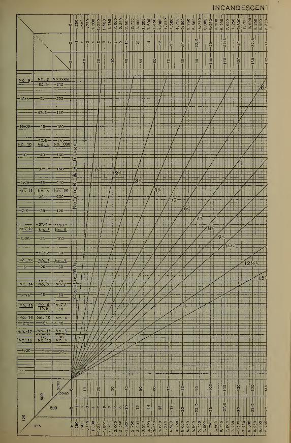
INCANDESCEN*
\ k <5 c © o © o ©o©oooocc©< i M 1i
i
i'
i III I1 1 1
III1 1300©COOOOO©0©0©000
DN0«l0NoSS!>.O«OfO«Sl?& 4- IB io IR !C(D(B<0(8NNNN*eCcC!rI, 1
I h v-(-"|- ,
JL . 1_ __!_. _T
\\
II III I I I eonL4.4.4...I.4.4..J
\ o o o O O © O\ot- WW-* in®?- I I t f-t t +l
S » »r « w £
NoTD- -N0.-3- / /
No. coooi
ii
i
;:
' '
| i / ' / / / /om / / / /. /210 Mi.'/; / /'
/ /I
/ /'
' 1/
/ :
-12.-5— 50 / / /200 { . :
i / /iiii : • ; ! . / •
' / i / / /
/ / / / /' /
190 I / :
/1 { /!:/!.' ;/
/ / J 1
-11-25- 45 1QA / /180
i ! / / 7 / 7 lTj*!
' / /' / / / / / /
!M! I / : / / / / / y... / / /
Nono-—Nor*-170 i
; i / / / 1// '
No. 000 a> I I i
i
/ i / / if ' /N] / / :
j 1' / /QU
, / / 1 / / /._ irn c
' ' / / y / / /1G0 -^ : 7 / / / / /
•/ : / / / /I
' ' '
'
< V / / / /- :
/ , / 7 / / / /rn rn i
i
, , '['/ / /;/' / /37. 5 1S0 W,
i i I', / / / / / / /is '
I I2< 1 /// / /
<sj'^- c / / I / ' '
/ / ' // / ^ ^uo pQ i r 7 / ';, / / y x -
r1.
i i 1 ; ; : i / : / /_ ! / /'::/ / /-MO.-11- —NO. 5- -NO.-00- -c-^ < / / /-ft.'—rr ~ rH /
1;
' :/ —-—-~/ / r—— / 7^- 7^- -7^
—
130 </>"i
'
. /'
; . 7 / / /C^ / ' ' / vY
D;c /] / / / 1
oil /: '
, / ; / / / f />T ' '
I / / / /_, „ m. /6^c / / / /120
i. / / / '/ / / / y /
i i / / / / / / / x X4—H—~t——/ -/—--V /77c ^ 1/—?'1 j. _y J.—__-/——J- z1— -7^ 7^
-HO._12I110 ' T / / / /
, . /^ / /QS / /NO o / / / / / / /8fc / /"°- " / / / /:.':!/ / / / y
/ / / / y / /- .. /tro •
;'' /''/'
i
/'i
'/ /•.// 9 l.c s
, ; / / / / / ' s/ / / ' / / / /n -
i' / / / / / / / 10', y-
i'
:/ / ' f / / s y/.// X90
\ ! J I / / / A A\ / ' / / / / / y . A •
_wo._13. _Np_7- -N0.-1 -'4-U f-W / /-v ^^_S -^—y -yfvixVnn „. -_
; / /—Hf H-hf—/-—/ ^^~X / / ' /^'^^lu
V~ IF / / / y 7 / .' A SS / / It ' / / / / A >'
/ / / / / / / /a A y^'^! / ' f / / / A A' -^| = J
,,, b / / / 7 / / / / / / y '->
HO—14 -NO.-8-i rjn% / ' ' / / / / / / yNo - 2 -5 / / / 7 / / / / / A A3 7 / / / ' / ^ ^ 7 A A A*j 7 / r / // / / / / A A^
—3-75— rn - J / / / / / / / / S A^00 O i Z
1 / / / / / S ^'// /'/// / / -1 A A/ / / / / y / / Lf A
-NO. 15 NO 9 N0— /: A-/—y-V- /-7^X-7 /
-~A^ A^-—12.5— ™ -H-h-'-f-/:/ / / / / / -A^— —^I ft////// > A \
-^0.-1
6
J I,, ^ I '/ '/ f , / f / / yf A \ '
MO. 4 , /. / / j / / / / / , y A2r5— -n 1 f ////// S ' y
-0 / 7 / / / / ; / / / z' ^: ,////// / / sf \ / _^
-no. -17- -N0.-11- MO 5 ////////.' >T /'^"°- ° 1 / / / / / / y / Z1 / -^™ / / i IV / /// Jn l>rkNor18- -N0.-12 w? r / y J / j{ / // / y s
NO. 6 \\l f//\///s j/ ^\ 1 7 /X//s y -^
/ / r// /1//V • /—^-25— -' '° \\1 v ,//jl' y S\\ 1 1
h
///a s -^ ' '
!
/ // Av//y 1 />- .!:-,;\ ////// '?^hilj///// y .'utiMffVo*\UJ///yy^iliW^^ Miljj^jS*- ||i . .
o
8 /8/ © Mo Mo 1lo! o o 1©y O i. I | CM CO It*-, tD « 1^
/2000
© 8 sl MS S !ico a> 1 r- 1 1 v- *- »— ^
/ 5
M 1
00 yw « *i- e s a c J « * ®J
ID "O ID-©c>i |n'>©oi ,r
V/
©eeccc-coccooecoooc' * 3 ON ifl n o|« Hi N 5 N in ,s O W C fj- C ()l «
,l I I I | I I | I l| I I
TTTT 1 T 1 13000CO©C©©COOOOOOCjmoiccmteoic cmOmomoiri)ir-ONCs5wii)r. ©CMiDr-»Oc>iinf>tj* inim" m' in it c 1 s n f i> a 00 00 c
1 ; 11, ! ill ill 1 1 1 1 ! I1
11 l 1

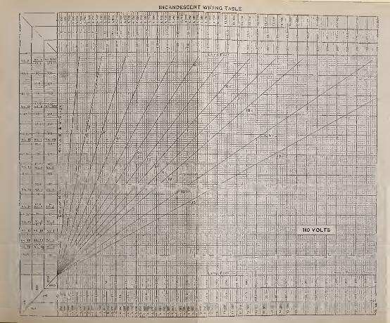
$m. JJTiRlrM1
1 1 -
!
"TT~T+~~r^T^-^r-
. 1'
i|| i [ I 1 I I I i j |
l
.
'
/-_
1'
\ V 1 / ''/" ' 71 1 : r*H '~—
.H :
| [
:
|. : U-Tf
,
;
'-".
:
Sp4-
M:
,;
•
y ] \- ', t 7 , : • l ... i 1 i
i i .
-,
' Hill 1 SHIP ? ;l.h .
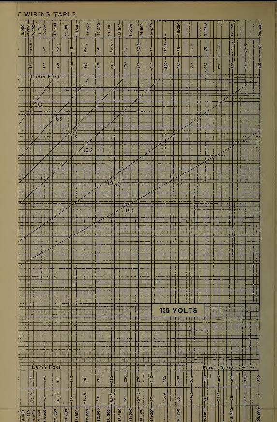
r WIRING TABLE
o> » <„ e~ O © ^ ~ w £ CO « *J..1.J..J. T._ . . 1 I E
r x x ^ —— 100 ©OO £ O ir 500 <£ in tj-
* in f° r^ 00 6r- -- ~" »- -- CNI
,__ .... 1
» lO |> | |) IB_;Oo3mr^©oJ'or'- cNinrsO <n!" ft'oo
y _ y t- -- CM cN^tN OOOOOoOO??CJCMCNCMCMtNWW<r<5
- ' / / /- ^ r X ^ 71 V y- ^ S x ^
_X _ i __:____ ^ _ £_ ___ X -- - - ^ 741 • z ::::"?::. ^
/ _- -^ „
- - • ^ ^ 7 - i^ ^ X ^ 7^~
1 y Z ^ ^ ^^X/ Z X __ X x 1
'/ / / / _____ X...^^ _ _'Av / /__ _J_ Zl x ~ x— XjLLM ZZ y ' Si__i__ J £- / £**
Z i ZtZZ 1- 12 it .-X 7:£___ i _ _ _/_ 4_ _r _
ix
—
r j ; :: /. x _,z?'--
-f ' J48Yc ^ X _,_£ ^ X XX"y i 7o/0
/ / s1
7 i / z ^ ^^ - .-
/ x / - ± / _H"
1 y -4-2^ ^ ! ~y 1 (_
X^ X^^^ 7 -^
^^ T ," '
_ ___zt_ _ _ ^z __ _-^-_ _ - ^__t _X - X ^ X "
Z i ^z ^ + _y ^^ - -L-
Z i z ^ S 3^X/ ^ /'m^ - ^3^f 7 / lvJ%
^7 *' Xt_ ,__Z __: ^,^_ ,.-____, _ ^—
fL\ X. 7 J7 it-,Z s S +'
X2 y * - * ? - ^'*Z)l / S - s y
,___ __ _X _____ _ -__ -.-^ _ _
v 7 A S __ _
- _/ ' -,^ _' X ^^ -i- it- ? ' _Z ^ IC-' -4-:~_ i .? __:_ ^^^ 1 _ _ _ _,_
|
_., ";_ _!__;$_*$:- —
-
_: -j_ ^_i/ ,?
/j!*" ! -^- -4-L
2-__--_- _: _«:-X I'l..
._ _^_ i _ __ _ __ __^ _ _ _ _ : s -t - it_ __| ^ __ _ ?^
-*2l i ^ „'_X i _i_ a _ _t X !__ .
-4- /- -
(
-__,_: ___ __._ ^.g'rf_ .
i / .'1 S __:\
•' >"1 _ ? it it _^ i
1 y -^1 • * ,•'S '
ZtHT __*,__^__ i 2
!/ i tt";?;_ i _J_±2! _i_
1
r -[> - t XX x^ ! t - -- - --X- - Xi ,^ 1 1 1
I 2" !
j^1
1 1
1> '
' __ __ __t_^ i
X X -t
i1
i1
1
1 1 1
.
110 VOLTS xX ' -i_
i
1
1
1
i
1r
._ |__ '
000 090000____|____l___l___l_-_I---I---i----jl
> id n in •
1 1 1
•p "° f ToOWiD^OCN^f^ 00II —
u
"9T000-
-9.-250- -9.-500- -9.-750- 10.-000-
10.50O-
11.-000-11.-500-
12.000-
I2r500-
13.000-
13r500- 14r000-
r — t X i= 2 c- 5 ,rs £> O5 O CM tf> ^- O
is S £ t 8
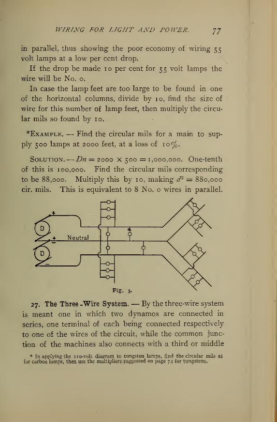
WIRING FOR LIGHT AND POWER. 77
in parallel, thus showing the poor economy of wiring 55volt lamps at a low per cent drop.
If the drop be made 10 per cent for 55 volt lamps the
wire will be No. o.
In case the lamp feet are too large to be found in one
of the horizontal columns, divide by 10, find the size of
wire for this number of lamp feet, then multiply the circu-
lar mils so found by 10.
*Example. — Find the circular mils for a main to sup-
ply 500 lamps at 2000 feet, at a loss of 10%.
Solution.—Dn = 2000 x 500 = 1,000,000. One-tenth
of this is 100,000. Find the circular mils corresponding
to be 88,000. Multiply this by 10, making d2 = 880,000
cir. mils. This is equivalent to 8 No. o wires in parallel.
27. The Three -Wire System. — By the three-wire system
is meant one in which two dynamos are connected in
series, one terminal of each being connected respectively
to one of the wires of the circuit, while the common junc-
tion of the machines also connects with a third or middle
* In applying the no-volt diagram to tungsten lamps, find the circular mils as
for carbon lamps, then use the multipliers suggested on page 74 for tungstens.
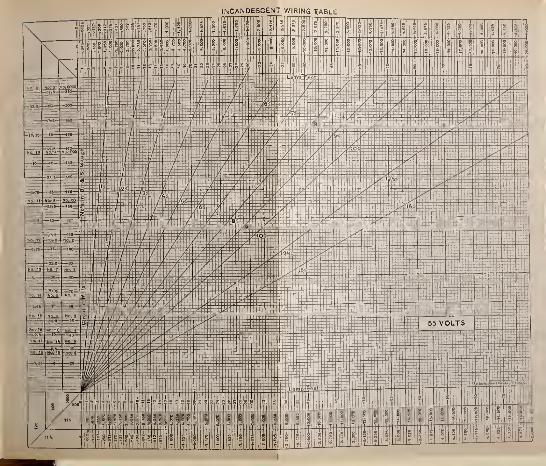
INCANDESCENT WIRING TABLE
\ . . : - •. II!||j||f li
1' ^
\ M.p;!l??| 1
'" :
:
§ I 1 | 1 § |i Si-
JS|
;
I1
T-i -'-'-At'- L:-^-'
--'--4^-
_4_i—
M
—>r
-
HI
:
:f:r
_J\ lL.A_M.-ir '
,. : .-
Wl i
::
^~
[
-
«:•
1||||- L
1
L-Ur
:- 55 VOLTS
,—\—
1:
is|—p-r- III 1 :
JS^^M 8 "^ ,5 | 5j.!|i :
|?;ji5^|l!S,|;;i :; ^| _"
! Dm!- 51
!'M ^1^- ?-^ • V

78 ELECTRICAL AND MAGNETIC CALCULATIONS.
wire of the circuit. The system therefore requires three
wires for its operation. The voltage between the outside
wires is twice the voltage of a single machine, while that
between the outside wires and the middle, or neutral wire,
is equal to that of each machine. When the system is in
operation two lamps are in series between the outside
wires, thus requiring one-half the current which the same
number of lamps would require on the two-wire system.
The diagram, Fig. 5, will make the details of the circuits
clear.
The three wires are usually continued out to the lamp
circuits, and these also often have three wires where there
is a very large number of lamps on each circuit. The
economy in wire is apparent from the following considera-
tions.
The voltage between the outside wires is double that in
the two-wire system and, as has been shown, the current is
one-half. Hence for a given per cent drop the volts drop
will be double that for two wires. The resistance of thep
wire is the volts drop divided by the current, or i? = —3
,
where the subscripts denote the kind of system. But
£z = 2,E2,and/3 = i.4 Hence Rz = -^ = 4-7^ That2 A * 2
is to say, the resistance for the three-wire system is 4 times
the resistance for the two-wire system. Therefore the
cross section of each wire is \ that of each wire in the two-
wire system.
To determine the wire for this system, then, apply the
rules for the two-wire circuit, and take \ the circular mils
so found.
WIRING FOR LIGHT AND POWER. 79
Example. — Find the size of wire for 200 lamps, novolts, at 200 feet, for 5 per cent drop.
Solution. — From (38), d 2 = 1.86 X Dn.
Therefore
d2 = 1.86 X 200 X 200 = 74>4°° c ir - mils.
\ of 74,400 = 18,600 cir. mils for 3 wires, No. 8, nearest.
The middle wire could usually be made smaller; but
should the number of lamps on the two sides of the circuit
be unequal, it has to carry the excess back to the machine.
It is therefore nearly always made the same size as the out-
side wires. The total copper then in the three-wire system
is f as much as for the same number of lamps on the two-
wire system ; for each lead in the former is \ of each in the
latter, and 3 leads make f of each, or | of both leads in
the latter. That is, if a certain system could be installed
using 2 wires for $500.00, it could be put in with 3 wires
for § of $500.00 = $187.50. This is partly offset, how-
ever, by the extra cost of installing, and by the necessity
of using two machines.
Several different methods * have been devised to over-
come the disadvantage of using two machines, though
they are but little used, if at all. An armature may have
two independent windings and two commutators to which
the circuits may then be connected, as with two machines.
In the second method, the generator is wound to give 220
or 440 volts, and a storage battery is connected across
the wires ; the neutral wire is then joined to the center of
the battery. Again, a third brush may be set for the
neutral wire to give half the potential of the machine.
* See Crocker's Electric Lighting, Vol. II., Chap. IV., for complete descrip-
tion and diagrams of the various three-wire systems.
8o ELECTRICAL AND MAGNETIC CALCULATIONS.
28. Original Problems. — 1. By the fall of potential
method find the gauge number of the wire to be used as
leads from house switchboard to lamp circuit junction box
65 feet, to supply 200 lamps, no volts, at 2^ volts drop.
Wire No. 3 B. & S.
2. Suppose the lamps in the above problem were 50
volt lamps wired for the same drop ; what size of leads
must be installed ? Wire No. o B. & S.
3. Determine the wire for the following system. From
the house switchboard a set of leads is run north 100
feet where a branch is taken off to a distributing point for
20 lights; 75 feet farther north another branch is run off
from leads for 15 lights; 50 feet still farther north on
leads is a junction box for 10 lights. The drop is 2 \volts to first branch, 1^ between the first and second, and
1 volt between second and third. Lamps are no volts.
Wire, first section, No. 7.
Wire, second section, No. 9.
Wire, third section, No. 13.
4. In the same way determine the size of the lamp cir-
cuit wires for a drop of 1 volt, if the lamps from the first
junction are at an average distance of 50 feet, from the
second 30 feet, and from the third 20 feet.
First No. 10B.&S.Second No. 14 B. & S. ) Nothing less than
Third No. 14 B. & S. ) 14 to be used.
5. Use the formula for wiring, and calculate the mains
WIRING FOR LIGHT AND POWER. 8
1
for 500 incandescent lamps, no volts, at a distance of
500 feet for a drop of 8% of the generator volts.
Wire 2 No. 00 in parallel.
6. The circuits for problem 5 run out from the distrib-
uting switchboard as follows: one circuit north 100 feet
for 100 lamps; one south 50 feet for 200 lamps; one
west 100 feet for 80 lamps; one east 150 feet for 80
lamps. Drop on leads 2^%. Determine the gauge number.
North No. 4.
South No. 4.
West No. 5.
East No. 3.
Note.— No. 4 wire could be used without any appre-
ciable disturbance of the regulation, and in practice
probably would be used in each branch.
7. Determine the lamp circuits in the last problem,
drop 1^%, and draw complete diagram of the system, the
following data being given. The north branch supplies
from the junction point 10 circuits averaging 10 lamps
each, distances from junction averaging 40 feet. The
south branch connects with four junction boxes near
together; from No. 1, 60 lamps are fed on 5 circuits
averaging 50 feet long; No. 2, 30 lamps on 4 circuits
averaging 25 feet ; No. 3, 80 lamps on 8 circuits, 30 feet
;
No. 4, 30 lamps on 3 circuits, 40 feet. The west branch
feeds two junctions; No. 1, 50 lamps on 4 circuits, 60
feet; No. 2, 30 lamps on 5 circuits, 50 feet. The east
branch supplies two junction boxes ; No. 1, 70 lamps on
7 circuits, 40 feet; No. 2, 50 lamps on 4 circuits, 50 feet.
82 ELECTRICAL AND MAGNETIC CALCULATIONS.
North No. 1 6, use No. 14.
No. 1, wire No. 14.
^ th ^ ^°* 2'
w*re "^°* I ^' use I4#
No. 3, wire No. 17, use 14.
^ No. 4, wire No. 14.
,, 7 ( No. 1, wire No. 14.West <' ^
( No. 2, wire No. 17, use 14.
C No. 1, wire No. 16, use 14.East ^ XT -at
^ No. 2, wire No. 14.
8. Use the wiring diagrams and verify the results
obtained in problems 1 and 2, for 30-watt tungstens.
9. By means of the diagrams verify problems 3 and 4.
10. Verify the results in problems 5 and 6 by means of
the diagrams. Also calculate for 40-watt tungstens.
n. Work out problem 7 by use of the wiring diagrams.
12. A town is to be wired, 3-wire system. Determine
the sizes of wire to be used ; also the machine volts and
line drops. Street mains run from the station i mile
north on Main street to the intersection of Union street,
and supplies east and west branches ; the one east runs
on Union street 500 ft., thence north on College street
250 ft. ; the one west runs on Union street 500 ft, thence
north on Congress street 250 ft. The Main street line
also continues north 500 ft. to Washington street, whence
it sends one branch east 500 ft., thence north on College
street 250 ft. ; also one branch west 500 ft, thence north
on Congress street 250 ft. The Main street line also
continues north from Washington street 400 ft. to State
street, whence one branch runs east on State street 500
WIRING FOR LIGHT AND POWER. 83
ft., and one west on State street 500 ft. There will be
about 500 lamps, no volts, fed from the first junction on
Main street, 300 on the east branch and 200 on the west
branch. There will be probably 200 on the east branch
at Washington street and 200 on the west branch. At
State street there will be about 100 lamps fed east and
100 west. It is decided to lose 8% on the Main street
feeder mains and 4% in the cross street lines, leaving
3 °fthence to lamps. See answers for °/ 's used.
First section main feeder requires 5 No. 0000
wires in parallel, 6°/c drop.
Second section 3 No. 000 wires in parallel, \\°f .
Third section 2 No. 00 wires in parallel, f %.First east branch No. 00 wire. First west branch
No. 1 wire.
Second east branch and west branch No. 1 wire.
Third east branch and west bra?ich No. 4 wire.
Machine volts 130 X 2 = 260.
Volts at branches 119.6.
Volts at junc. lamp leads n 4.4.
Volts at beginning lamp circuits n 1.8.
Drop on mains 10.4 volts.
Drop on branches 5 volts.
13. Continue problem 12 as follows, drawing complete
diagram. Each one of the branches described above
feeds into the center of a north and south lead wire run-
ning each way 125 feet to the center of lamp circuits.
The first lead on College street supplies 150 lamps each
side of feeding point, drop 2%. The second on Col-
lege street supplies 75 lamps on the north and 125 on
84 ELECTRICAL AND MAGNETIC CALCULATIONS.
the south of feeding point. The third supplies 75 lamps
south and 25 north of feeding junction. The first on
Congress street supplies 150 lamps north and 50 south of
feeding point. The second on the same street feeds 100
lamps each way. The third, 40 lamps north and 60 south.
Drop in all leads is 2%.First, College street, No. 6 wire each way.
Second, College street, No. 7 S. and No. 10 N.
Third, College street, No. 10 S. and No. 14 N.
First, Congress street, No. 6 N. and No. 12 S.
Second, Congress street, No. 8 N. and S.
Third, Congress street, No. 12 N. and No. 10 S.
14. There are installed at a distance of 300 feet from
the street mains 5 motors in a factory: 2 of 20 H.P.
each, 1 of 40 H.P. and 2 of 50 H.P. each. What size
of wire must be installed for 5 °fdrop, the motors being
220 volt machines, and assuming the load not to exceed
§ of the rated power ?
2 No. 00 wires in parallel.
15. A motor of 200 H.P. is employed at full load to
operate a line of counter shafting in a foundry. Aspecial wire is erected, running from the general power
station 500 feet distant. The E.M.F. at the station
switchboard is 250 volts, and the motor requires 220
volts. Determine the size of wire to be installed.
2 No. 00 wires in parallel.
BATTERIES. 85
VI.
BATTERIES.
29. Connection of Cells for Combined Output.— Applying
Ohm's law to the electric cell, the current delivered is
in which E is the electromotive force in volts measured
between the electrodes when there is no circuit connected.
R is the external, and r the internal resistance. E and r
are called the " cell constants."
Example.— Through what external resistance must a
cell be connected whose constants are E = 1.5 volts and
r = \ ohm, so that 1 ampere may be obtained ?
Solution.—
R + r R + 0.2
Hence R + 0.2 = 1.5.
Whence R = 1.5 — 0.2 = 1.3 ohms.
Example.— How much current will flow in a circuit of
5 ohms external resistance in which is placed a cell whose
E.M.F. is 2 volts and internal resistance ^ ohm ?
I=j£rr =:j^ = °-363 amPere -
Series Connection.— Whenever any number of E.M.F/s
are connected together in series, the total E.M.F. is their
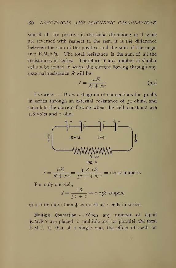
86 ELECTRICAL AND MAGNETIC CALCULATIONS.
sum if all are positive in the same direction ; or if some
are reversed with respect to the rest, it is the difference
between the sum of the positive and the sum of the nega-
tive E.M.F.'s. The total resistance is the sum of all the
resistances in series. Therefore if any number of similar
cells n be joined in series, the current flowing through any
external resistance R will be
Example.— Draw a diagram of connections for 4 cells
in series through an external resistance of 30 ohms, and
calculate the current flowing when the cell constants are
1.8 volts and 1 ohm.
h - + - +. - +
E-1.8 r-i
A/WWWWWWV
/= nE
R-30
Fig. 6.
4 X 1.8
R + nr 30 + 4 X 1
For only one cell,
= 0.212 ampere,
1 = 1.80.058 ampere,
3° + 1
or a little more than 1 as much as 4 cells in series.
Multiple Connection.— When any number of equal
E.M.F.'s are placed in multiple arc, or parallel, the total
E.M.F. is that of a single one, the effect of such an
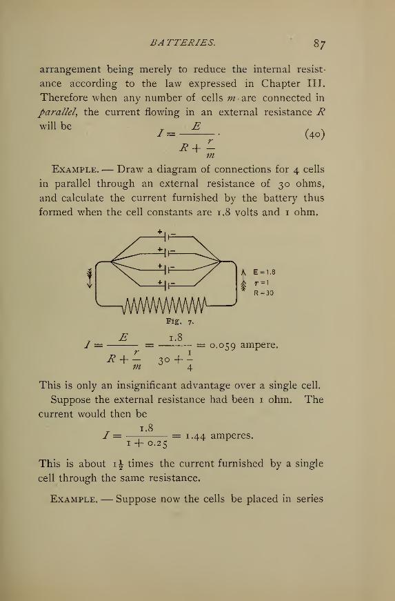
BA TTERIES. 87
arrangement being merely to reduce the internal resist-
ance according to the law expressed in Chapter III.
Therefore when any number of cells m are connected in
parallel, the current flowing in an external resistance Rwill be E , N~
'
(4o)IR + m
Example.— Draw a diagram of connections for 4 cells
in parallel through an external resistance of 30 ohms,
and calculate the current furnished by the battery thus
formed when the cell constants are 1.8 volts and 1 ohm.
wwwwvwvw
/ =E
R + m
Fig. 7-
1.8
3° + -
= 0.059 ampere,
This is only an insignificant advantage over a single cell.
Suppose the external resistance had been 1 ohm. The
current would then be
1.8/ =
1 + 0.25= 1.44 amperes.
This is about 1^ times the current furnished by a single
cell through the same resistance.
Example. — Suppose now the cells be placed in series
88 ELECTRICAL AND MAGNETIC CALCULATIONS.
through i ohm external resistance ; what current will be
obtained ?
r 4X1.8Solution.— I = = 1.44 amperes.1+4X1 ^ F
This is exactly what was given when the cells were all in
parallel.
Example.— Use the cells first in series, then in par-
allel upon 1 ohm external resistance.
Solution.— For series,
t 4 X 1.8I = = 1.60 amperes.
0.25 + 4
1 8For parallel, /"=
-j- = 3.6 amperes.\j ' \j
The parallel arrangement gives more than twice the
current given by the series connection.
Comparing the results of this problem with the pre-
vious problem having 30 ohms external resistance, it is
apparent that for large external resistances relative to the
battery resistance, the series method gives the larger
current ; while for relatively small external resistances,
the parallel method may give the better results.
Multiple-Series Connection.— Sometimes, however, a better
advantage is obtained by combining these two methods of
connection in what is called the multiple-series method.
The principles are the same as before ; calling n the
number in series and m the number in parallel, the
formula for / becomes
T _ U^
R nr (41)
m
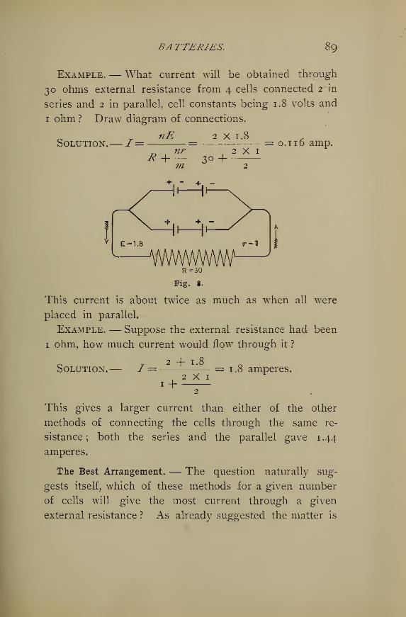
BA TTERIES. 89
Example. — What current will be obtained through
30 ohms external resistance from 4 cells connected 2 in
series and 2 in parallel, cell constants being 1.8 volts and
1 ohm ? Draw diagram of connections.
nE 2 X 1.8Solution.— I= = = o. 1 1 6 amp.
vwwwwwR=30
Fig. S.
This current is about twice as much as when all were
placed in parallel.
Example. — Suppose the external resistance had been
1 ohm, how much current would flow through it ?
,.2 + 1.8Solution.— I = = 1.8 amperes.2x1
1 H2
This gives a larger current than either of the other
methods of connecting the cells through the same re-
sistance ; both the series and the parallel gave 1.44
amperes.
The Best Arrangement. — The question naturally sug-
gests itself, which of these methods for a given number
of cells will give the most current through a given
external resistance ? As already suggested the matter is
9<D ELECTRICAL AND MAGNETIC CALCULATIONS.
roughly decided by a comparison of external and internal
resistances. An observation of the numerical values
given by the formulae for these three cases, when the
external resistance was i ohm, shows that in the series
connection the internal resistance, 4 ohms, is larger than
the external ; in the parallel connection the internal,
0.25 ohm, is smaller than the external ; in the parallel-
series connection the internal is equal to the external.
Hence the conclusion is that the maximum current is
obtained from a given number of cells connected to a given
resistance when they are so arranged that the internal resis-
tance is equal to the external.
This is shown also from the following considerations.
Since nE E
X + ? *+ r-m n m
R rit is apparent that I will be a maximum when 1
n mis a minimum, for the numerator E is constant, being
R rthe E.M.F. of one cell. Now the product of— and — =
n mRr— is a constant, R and r both being constant, and mnmnthe whole number of cells in the battery. It is a well-
known principle and can be easily illustrated by a sim-
ple numerical example, that the sum of two quantities is
the least, their product being a constant, when the two
R rquantities are equal. Therefore 1 will be a minimumz n m
R r nrwhen — = — ; that is when mR = nr, and R = But
n m m
BATTERIES. 9
1
nris the internal resistance of the battery. Therefore
mthe external and i?itemaZ resistances must be equal for the
greatest rate of flow. But under these circumstances only
one-half the total energy is expended in the external cir-
cuit, the other half being spent in the battery resistance.
The efficiency of a battery arranged for greatest current
is therefore 50%.
30. The Best Arrangement for a Required Current.—To find the number of cells for a required current it is
only necessary to apply the general formula for the con-
nection of cells, 11E
„ nrR+ —m
remembering that for the greatest current the cells mustnr
be arranged so that R=m
Example.— How many cells arranged in series are
necessary for 4* amperes through a resistance of \ ohm,
the cell constants being 2 volts and \ ohm ?
Solution. — Taking n = the number of cells in series
and m = the number in parallel, we have
11E 2 n , N/= = = 4| (1).nr 1 n b K J
R + — - + -m 2 4
m = i, all being in series. Clearing (1)
2 n = 2.4 + i-2 n\
and 0.8 n = 2.4 ; n = 3 cells.
Example. — How many cells in parallel will give
3.6 amperes through an external resistance of J ohm,
cell constants 1.8 volts and 1 ohm?
92 ELECTRICAL AND MAGNETIC CALCULATIONS.
c _ nE I X 1.8Solution.— 7 = = = 3.6 amperes.
#24 ;/z
From this 1.8 m — 0.9 #2 = 3.6 ; and m = 4 cells.
Example.— How many cells and what arrangement
will be necessary to supply 3 amperes, the external resist-
ance being if ohms, and the cell constants 2 volts and
1 ohm?
o T nE 2n NSolution.—/= = = 3 (1),^ nr nE +— if + ~m m
and 2 /z = c + — (2).
nr ^ n .
Since — = R = if, #z = —- , since r = vw 3
if
Substituting this value of ^ in (2),
3 n2/* = S + V =
S + 5= IO
'
and ^ = 5 ce^s m series.
Also m = —- = -^- = 5 x f = 3 cells in parallel.
Hence it will require 15 cells, 5 series, 3 parallel.
For a required current at a given voltage the following
rules may be applied with satisfaction.
Divide the cell E.M.F. by its resistance, (a) If this short
circuit current is twice or more than twice the required cur-
rent, the cells will all be in series, and the number of cells
will be E1 , N
BA TTERIES. 93
Ex
is the required external E.M.F., E is the cell E.M.F.,
r the internal resistance, and / is the required current.
(b) If the short circuit current is less than twice the re-
quired curre7it and more than its equals or less than equal
and more than its half, or less than the half a?id more thaii
itsfourth, and so on, place as many cells in parallel as 7vill
make the short circuit current twice or more than twice the
required current, then apply (42) for the number to be used
in series,
(c) If the short circuit cu?'re?it is 1, \, \, \, etc., times
the required curre?it, place as many cells i?i series as will
make the E.M.F. double the required line voltage, and the?i
put enough in parallel to make the battery resistance equal to
the external resistance,— Sloane.*
Example. — There are 4 50-volt, 50-ohm lamps in par-
allel. Cell constants are 1 .8 volts average and I ohm. Howmany cells and what arrangement will supply the lamps ?
1 8Solution.— Short circuit current = -j- =9 amperes.
5Required current /= f§ X 4 = 4 amperes.
Hence, using (a),
£1 5°n = -- = 50 cells in series.E — Ir 1.8-4X5
Example. — Using similar cells, how many will it take
for 8 lamps similar to the above ?
• •1.8
Solution.— Short circuit current = -=- = 9 amperes.
5
Required#current / = %% X 8 = 8 amperes.
* Sloane, Arithmetic of Electricity, p. 69 et seq.
94 ELECTRICAL AND MAGNETIC CALCULATIONS.
Hence, using (<£), place 2 cells in parallel giving
9 X 2 = 18 amperes, cell current.
Whence
E\ 5° 11n =— — = —t £
—
z r = ko cells in series.E-Ir i.8-8x|x|
The whole number required is mn = 2 x 50= 100 cells
arranged 2 in parallel and 50 in series.
Example.— Suppose there were 18 lamps in parallel,
how many cells would be necessary ?
Solution. — Short circuit current = 9 amperes.
Required current /== |-g. x 18 = 18 amperes.
Hence, using (V), we must place in series
n =2-g± = ^-p = 5 6 cells
>
giving an internal resistance of
-5- X 56 = ni ohms.
Therefore we must place in parallel cells enough to re-
duce to AO. = 2-I ohms. Hence m in parallel equals
ni-f-2-I = 4 cells. Therefore there will be required
mn = 4 x 56 = 224 cells.
31. Arrangement of Cells for a Required Efficiency. —As for any generator of electrical energy, the efficiency of a
battery is the ratio of the external energy to the total energy
developed, and this is the same as the ratio of the external
to the total resistance in the circuit.
BA TTERIES. 95
Eff. = -tA- ' Ui)R+r K*6J
In order to obtain a formula for r, multiply (43) by R + r,
when R x eff. + r x eff . = R ; or
*(,-eff.).r - dl (44)
Example. — What is the efficiency of a battery deliv-
ering current through an external resistance of 50 ohms
when the battery resistance is 10 ohms ?
Solution. — Eff. = —^— =—^— = 831%.R + r 50+10 ° 3 '
Example. — What must be the internal resistance of a
battery when the external is 60 ohms in order that the
efficiency will be 66f% ?
iP(i-eff.) 60(1 -.66J)Solution.—r=—-— =—-————— = xo ohms.eff. o.66§ °
R (1 - eff.) . . .
Since r = —-—= gives the internal resistance, theen.
total resistance is expressed evidently by
™ , n H(i — eff.)Total resistance == R H —-= '-
en.
If the required current is /, then the E.M.F. of the battery
to give a certain current through a known resistance at a
required efficiency will be, from Ohm's law,
R (1 - eff.)"-E = \S +eff.
/• (45)
Example.— Required to provide storage cells for 450-
volt, 50-ohm incandescent lamps in parallel. Cell con-
stants 2 volts and T\j- ohm, the battery to work at 75%efficiency.
96 ELECTRICAL AND MAGNETIC CALCULATIONS.
Solution.—
Hence the number of cells in series will be
66.6n = = 34 cells.
Also for 75% efficiency the cells must be arranged so
that
i?(i-eff.) ^(1-0.75) , .
r = iv = ^-^ — = 4.16 ohms.eff. 0.75
But the internal resistance of the 34 cells in series is
34 x ro = 3-4 onms > or already less than is required for
75%. Therefore 34 cells in series meet the require-
ments and the efficiency will be
Eff. = I2
j_5 =78%.
12.5+3.4
32. Charging Storage Cells.— In charging batteries
the E.M.F. applied must be equal to the ohmic drop in
the wires and cells, plus the battery E.M.F. which acts as
a counter electromotive force ; it also must vary with the
condition of charge in the cells, rising as the battery ap-
proaches full charge.
Example.— A battery of 45 cells is arranged in series
for charging. Each has an internal resistance of 0.005
ohm and a counter E.M.F. of 2.1 volts. The leads have
a resistance of 0.05 ohm. The cells take a charging cur-
rent of 100 amperes ; what must be the terminal voltage
of the dynamo ?
BA TTERIES. 97
Solution. —The ohmic drop = (0.005 x 45 + °-°S) X 100
= 27.5 volts.
Counter E.M.F. = 2.1 X 45 = 94-5 volts.
Hence the total voltage applied from dynamo switch-
board must be
E = 94.5 + 27.5 = 122 volts.
Example.— Find the current at the beginning and end
of the charge of 40 cells in series, each having 0.002 ohm
internal resistance, leads 0.07 ohm, when the charge lasts
6 hours and the cell E.M.F. changes during charge from
2 volts to 2.5 volts. The generator remains uniformly at
125 volts.
Solution.—Counter E.M.F. at first = 40 x 2 = 80 volts.
Counter E.M.F. at end = 40 x 2.5 =100 volts.
Resistance of circuit = (40 x 0.002) + 0.07
= 0.15 ohm.
Ohmic drop at first = 125 — 80 = 45 volts.
Ohmic drop at end =125 — 100 = 25 volts.
Hence from Ohm's law,
T£1 45J1
= —- = —— = 300 amperes,K 0.15
and _ £2 25Jo = —pr = = 166.66 amperes.R 0.15
33. The E.M.F. of Cells from the Available Heat of
Chemical Action. — The source of the electrical energy of
a cell is the chemical energy transformed in it. Neglect-
98 ELECTRICAL AND MAGNETIC CALCULATIONS.
ing the losses which occur more or less in all cells, the
electrical energy obtained is equivalent to the energy of
chemical action. Now when elements combine or sepa-
rate heat is liberated or absorbed. Therefore we have a
measure of the chemical energy in the amount of heat ex-
changed. The amount of an element separated is also
strictly proportional to the quantity of electricity flowing.
These considerations furnish the principles for determining
the E.M.F. necessary to separate certain chemical com-
pounds, or produced by known chemical separations and
combinations taking place in a cell.
The atomic weight of an element is the weight of its
atom relative to that of hydrogen, H, which is i.
The valence of an element is the number of hydrogen
atoms to which it is equivalent in combining power, or the
number of hydrogen atoms which would directly combine
with or replace it. Thus water, H20, consists of two
atoms of hydrogen held to one atom of oxygen. Hence
O has a valence, or holding power, of 2.
The chemical equivalent of an element is its weight rela-
tive to hydrogen which enters into combination. In other
words, it is the weight of the element which would com-
bine with unit weight of hydrogen. It is obtained by
dividing the atomic weight by the valence.
For example, in H2 the atomic weight of O is 15.96
;
that of H is 1. But 15.96 of O is equivalent to 2 x 1 = 2
of hydrogen. Hence each unit of H is equivalent to
15.96-^2 = 7.98 of O ; that is to say, each gram of H will
require for combination 7.98 grams of O. The chemi-
cal equivalent of oxygen is 7.98, or its atomic weight 15.96
divided by its valence 2.
BA TTERIES. 99
The electrochemical equivalent of an element is the
weight of it expressed as the fraction of a gram which will
be separated by one coulomb of electricity. Clearly the
electrochemical equivalent is proportional to the chemical
equivalent. Thus i coulomb separates 0.00001038 gram
of hydrogen, also 0.0000828 gram of oxygen, and these
are in the same ratio as 1 to 7.98, or as the chemical
equivalents. If we take the reciprocal of the electro-
chemical equivalent we obtain the quantity of electricity
necessary to separate 1 gram of the element. See table
of chemical constants.
Example.— Obtain the formula to be used in obtaining
the electromotive force in volts produced in any cell whose
thermal equivalents are known ; that is when the calories
of heat formed or absorbed in the chemical reactions can
be obtained.
Solution.— The electrical energy developed in any
cell is
Energy = Eli.
The available heat energy for transformation into electri-
cal energy is
Heat=/.#;
in which H is the free heat in calories due to chemical
action, and ./is Joule's Equivalent, or the ergs of energy
represented by each unit of heat = 4.19 x io7. If ex-
pressed in ergs the electrical energy will be
Ee= Elt x io7 ergs.
Therefore
JH= Elt x io7 = 4.19 x io7 x H.
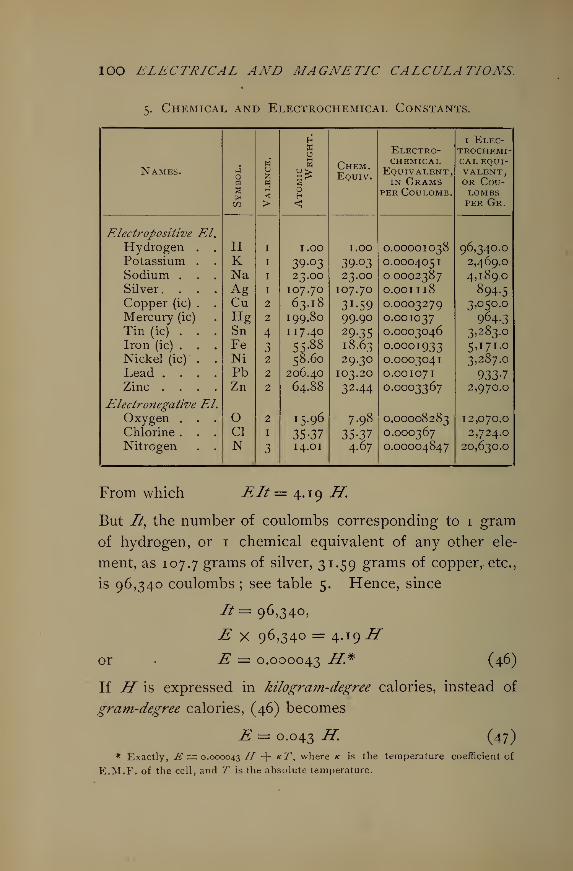
IOO ELECTRICAL AND MAGNETIC CALCULATIONS.
5. Chemical and Electrochemical Constants.
H 1 Elec-X Electro- trochemi-
Names.M
wu
w
Chem.Equiv.
chemicalEquivalent,in Grams
cal equi-VALENT,or Cou-
a< H per Coulomb. lombs
tfl > < per Gr.
Electropositive ELHydrogen . . H I 1.00 I.OO O.OOOOIO38 96,340.0Potassium . . K I 39-03 39.03 O.OOO4051 2,469.0
Sodium . . . Na I 23.00 23.OO O.OO02387 4,189.0
Silver. . . . Ag I 107.70 IO7.70 O.OOII18 894.5Copper (ic) . . Cu 2 63.18 3 J -59 O.OOO3279 3,050.0
Mercury (ic) Hg 2 199.80 99.90 O.OOIO37 964.3Tin (ic) . . . Sn 4 117.40 29-35 O.OOO3046 3,283.0
Iron (ic) . . . Fe 3 55.88 18.63 O.OOOI933 5,171.0
Nickel (ic) . . Ni 2 58.60 29.30 O.OOO3041 3,287.0
Lead .... Pb 2 206.40 103.20 O.OOIO7
1
933-7Zinc .... Zn 2 64.88 3 2 -44 O.OOO3367 2,970.0
Electronegative El.
Oxygen . . . O 2 15.96 7.98 O.OOO08283 12,070.0
Chlorine . . . CI 1 35-37 35-37 O.OOO367 2,724.0
Nitrogen . . N 3 14.01 4.67 O.OOOO4847 20,630.0
From which Elt = 4.19 H.
But It, the number of coulombs corresponding to 1 gram
of hydrogen, or 1 chemical equivalent of any other ele-
ment, as 107.7 grams of silver, 31.59 grams of copper, etc.,
is 96,340 coulombs ; see table 5. Hence, since
It— 9 6 >34-o,
E x 96>34o = 4.19^
or • E = 0.000043 H* (46)
If H is expressed in kilogram-degree calories, instead of
gram-degree calories, (46) becomes
E = 0.043 H- (47)* Exactly, E — 0.000043 H -f- kT, where k is the temperature coefficient of
E.M.F. of the cell, and T is the absolute temperature.
BATTERIES. IOI
We thus obtain the electromotive force from the result-
ant heat of chemical action, keeping in mind that the
result can only be approximate because of local action
and heat absorbed from or given up to surroundings.
The heats of combination of many ions, that is atoms or
groups of atoms, have been 'determined. See table 6 for
the heats resulting from the chemical reactions taking
place in the most common cells. It is to be observed
that H in the formulae is the algebraic heat ; that is, the
difference between the heats of formation and those of
disintegration in the cell.
Example.— What is the minimum voltage a cell maypossess to decompose water, H2 ?
Solution.— i gram H combining with 7.98 grams Oliberates 36,500 calories; see table 6. Hence to separate
them an equivalent amount of energy is necessary.
Therefore
E = 0.000043 x 36,500 = 1.56 volts.
Example.— What is the approximate E.M.F. of the
Daniell cell ?
Solution. — In this cell the elements are
ZincI
sulphuric acid copper sulphate|copper.
The chemical reactions are
Zn + H2S04= ZnS04 + H2 . (1)
CuS04 + H2 = H2S04 + Cu. (2)
Calories.
'Heat liberated by the formation of ZnS04= 53,500(i)-j Heat absorbed by the separation of H2S04
= 36,5oo
.Heat available for transformation =17,000
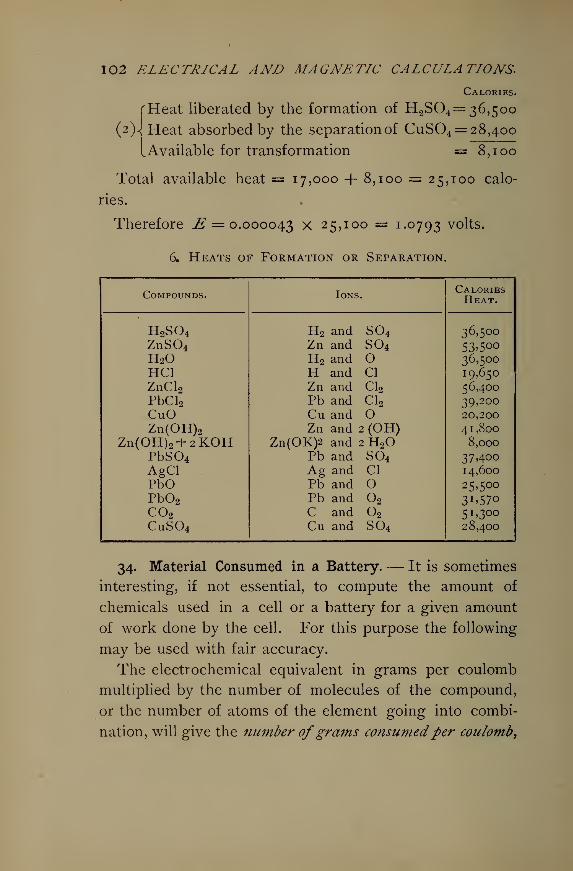
102 ELECTRICAL AND MAGNETIC CALCULATIONS.
Calories.
'Heat liberated by the formation of H2S04= 36,500
(2)^ Heat absorbed by the separation of CuS04= 28,400
^Available for transformation = 8,100
Total available heat = 17,000 + 8,100 = 25,100 calo-
ries.
Therefore .# = 0.000043 X 2 5> IO° = I -°793 volts.
64. Heats of Formation or Separation.
Compounds. Ions.CaloriesHeat.
H2S04 H2 and S04 36,500ZnS04 Zn and S04 53'500H2O H2 and O 36,500HC1 H and CI 19,650ZnCl2 Zn and Cl2 56,400PbCl2 Pb and Cl2 39,200CuO Cu and O 20,200
Zn(OH)2 Zn and 2 (OH) 41,800Zn(OH)2+2KOH Zn(0K)2 and 2 H2 8,000
PbS04 Pb and S04 37400AgCl Ag and CI 14,600
PbO Pb and O 25,500Pb02 Pb and 2 3^570co2 C and 2 51,3°°CuS04 Cu and S04 28,400
34. Material Consumed in a Battery.— It is sometimes
interesting, if not essential, to compute the amount of
chemicals used in a cell or a battery for a given amount
of work done by the cell. For this purpose the following
may be used with fair accuracy.
The electrochemical equivalent in grams per coulomb
multiplied by the number of molecules of the compound,
or the number of atoms of the element going into combi-
nation, will give the number ofgrams consumedper coulomb,
BATTERIES. 103
or per ampere-second. If this result be divided by the
voltage of the cell, the result will be in grams per watt.
This now multiplied by 3600 will give the number ofgrams
usedper watt-hour.
Hence Z X N , , oxw =——— X 3600. (48)
In this w is the weight in grams per watt-hour ; Z is the
electrochemical equivalent ; N is the number of mole-
cules or atoms entering combination and is obtained
from the chemical equation ; E is the cell E.M.F.
Example.— How much zinc is used up in a Daniell
cell working on a total resistance of 10 ohms for 1 hour ?
Solution.— For zinc, Z = 0.0003367 ; E = 1.08 volts.
/= —— = 0.108 ampere. The chemical equation is
Zn+ H2S04 = ZnS04 + H2 .
Hence there is one atom of Zn entering into combination.
Hence
0.0003367 X 1 .
w = ^~i X 3600 = 1.12 grams per watt-hour.1.08
Total watt-hours = 1.08 x 0.108 x i=E x ^X hrs.
= 0.11664.
Therefore total zinc dissolved in 1 hour is
W = 1. 12 x o. 1 1664 = 0.1306 grams.
The work may be slightly simplified by using a formula
for total weight at once, obtained by multiplying the
104 ELECTRICAL AND MAGNETIC CALCULATIONS.
formula for grams per watt-hour by the formula for the
number of watt-hours.
ZxiV^X36oo __ . rri^ TTW == =-£ x EI x hours = 3600 ZNI X hours,
or W= 3600 ZNIT, (49)
in which W is the total weight separated or combined, Nis the number of atoms or molecules combining, /is the
current in amperes, and T is the time in hours during
which the current flows. If E and R are known — may
be put in place of /. The formula may be still further
shortened by getting Z, the electrochemical equivalent, in
grams per coulomb-hour, then (49) becomes
W=ZNIT. (50)
Example.— How much CuS04 is used up under the
conditions named in the last problem ?
Solution.— The chemical equation is
CuS04 + H2 = H2S04 -f- Cu.
Hence 1 molecule of CuS04 is separated, and N== 1.
For copper, Cu, at. wt. = 63.18. For (S04) at. wt. =32 + (15.98)4 = 95.92. Total molecular weight CuS04
=63.18 + 95.92 = 159. 1. Z for Cu = 1. 18 grams per
coulomb-hour. For CuS04 ,
Z = 1. 1 8 X s = 2.9 grams per coulomb-hour.63.18
Therefore from (50)
W'= ZNIT= 2.9 x 1 X 0.108 x 1 = 0.313 gram.
BATTERIES. 105
35. Original Problems. — 1. What is the greatest ex-
ternal resistance that may be used when the battery con-
stants are 5 volts and 2 ohms, in order that \\ amperes
may be obtained ? R — 1.33 ohms.
2. It was observed that a cell whose electromotive
force is 1.8 volts gave 1 ampere through an external re-
sistance of 1 ohm; what was the internal resistance of the
cell ? r = 0.8 ohm.
3. What is the E.M.F. of a cell whose internal resis-
tance is 1 ohm, when 1 ampere flows through an external
resistance of 1 ohm ? E = 2 volts.
4. The cell constants are 2 volts and \ ohm. Re-
quired 5 amperes through an external resistance of 1.5
ohms ; how many cells joined in series will be required ?
n = 10 cells.
5. Can 5 amperes be obtained through the same resis-
tance with the cells joined in parallel ? Show why.
6. What must be the internal resistance of each cell
and of the whole battery when 5 cells joined in parallel
through an external resistance of 0.835 onm giyes 2
amperes, E being 1.75 volts ? Each cell = ^ ohm.
Battery = ^ ohm.
7. Which is the better arrangement of 4 cells whose
constants are two volts and \ ohm, series or parallel,
when the external resistance is 20 ohms? Is there any
better arrangement of 4 cells ? (a) Series, (b) No.
8. What is the largest external resistance that can be
used in 7, in order that the parallel connection will give
a current equal to the series connection ?
R = 0.5 ohm.
I06 ELECTRICAL AND MAGNETIC CALCULATIONS.
9. What current will be obtained under the conditions
of problem 8 when two of the cells are placed in series
and 2 in parallel? ^=4 amperes.
10. Find the number of these cells required in parallel
when 5 are placed in series to supply small lamps of
5 ohms resistance with 1.8 amperes of current.
m = 5 cells in parallel.
11. Find the whole number of cells to be used under
the following conditions : cell constants 2 volts and
\ ohm external resistance 10 ohms; when n are put in
series and m in parallel the current is 0.97 ampere ; but
when m are put in series and n in parallel only 0.78
ampere is obtained. mn = 4 x 5 = 20 cells.•
12. Group the cells in problem 11 so as to derive the
greatest possible current under the conditions given.
Determine the efficiency in 11 and 12.
Place 20 in series.
Eff. 11 =97.5%.Eff. 12 = 71.4%.
13. What is the least number of cells and their
arrangement for 2 amperes through an external resis-
tance of 1.5 ohms, cell constants 2 volts and \ ohm ?
11 = 3 cells in series.
m = 1 cell in parallel.
14. Ninety cells whose internal resistance is each
1 ohm are available for a circuit whose resistance is
10 ohms ; arrange the cells for the greatest current.
n = 30 cells in series.
m = 3 cells in parallel.
BATTERIES. \OJ
15. What is the least number and the arrangement of
cells of 2 volts 4 ohms each, when 1 ampere is desired in
an external resistance of 15 ohms?
n = 15 cells ; m = 4 cells.
16. There are 4 uo-volt, 220-ohm lamps in parallel;
storage cells are at hand of 2 volts and I ohm each. Howmany cells will it require to give the necessary current ?
n = 69 cells in series.
17. Suppose the cell constants were 2 volts and 1 ohm;
what number and arrangement would be required in
problem 16? n = no ; m = 2 ; total 220.
18. If the E.M.F. required in the circuit be 50 volts
and the current 5 amperes, cell constants 2 volts and
\ ohm, how many cells will be required ?
n = 37 ; m = 2 ; total 74 cells.
19. Solve problem 15 for 60% efficiency.
n = 13 ; m = 5.
20. How many cells would be required in problem 16
to work at 75% efficiency ? n = 74 cells.
21. Solve problem 17 for 80% efficiency.
n = 69 ; m = 5 ; total 345.
22. What is the least voltage a cell may have to be
used for decomposing hydrochloric acid, HC1, when
platinum electrodes are used ? E = 0.84 volt.
23. Zinc and platinum are used as electrodes in simple
HCL What will be the maximum E.M.F. of the cell?
E = °-7353 volt'
108 ELECTRICAL AND MAGNETIC CALCULATIONS.
24. Suppose copper sulphate, CuS04 be used in the
last cell in a porous cup with a platinum, Pt, electrode.
What will be the cell E.M.F. ?
E = 1.0836 volt.
25. The final action in the " silver chloride " cell is
represented by the equation
2 AgCl + Zn = ZnCl2 + 2 Ag.
What is its E.M.F. ? E = 1.17 volts.
26. How much zinc, Zn, will be used in 10 hours
when 10 Daniell cells are connected 5 in series and 2
in parallel through a resistance of 5 ohms, cell constants
being about 1.08 volts and 2 ohms?
Zn used = 6.54 grams.
27. How much CuS04 will be used in the above ar-
rangement? CuS04 used = 15.66 grams.
28. The final action in the Becquerel cell is represented
by the equation, PbS04 + Zn = ZnS04 + Pb.
Determine the E.M.F. and the amount of Pb separated in
a cell working 10 hours on 1 ohm resistance?
E = 0.69 volts.
29. Find the E.M.F. of the Edison-Lelande cell whose
chemical formulae are as follows
:
(1) Zn + 2H2 O =Zn (OH)2 + H2 .
(Zn (OH)2 + 2KOH = Zn (OK)2 -f 2H20.
**'IH
2 + CuO = H2 + Cu.
BATTERIES. IO9
Solution.— In the first and second reactions 41,800+8000 calories are set free. In the last reaction 20,200
calories are absorbed. Hence the available heat is 49,800
— 20,200 = 29,600 calories. Hence
E = 29600 x 0.000043 = I,2 7 v°lt-
30. Twenty small storage cells are to be charged with
a minimum of 10 amperes. If the highest cell E.M.F. is
2.5 volts, cell resistance 0.008 ohm, and wire resistance
0.14 ohm, with what voltage should the cells be charged ?
If a no-volt incandescent machine is the only one avail-
able, how can arrangements be made to charge the cells
by means of it ?
(a) Charging E.M.F. = 53 volts.
(b) Place 10 50-volt lamps in parallel, and
in series with the cells to be charged
;
then reduce the machine voltage by
means of its field rheostat till 10 am-
peres are obtained.
31. There are 50 storage cells whose constants may
be taken at 2.1 volts and 0.002 ohm to be charged from
a 250-volt circuit. The connecting wires, leads, etc.,
have about 0.9 ohm resistance ; how much additional
resistance must be added in series so that the cells maybe charged with about 40 amperes of current ?
R = 2.6 ohms.
32. How many storage cells may be charged in series
on a no-volt circuit when 50 amperes are required, the
cell E.M.F. being about 2 volts, resistance 0.004 ohm,
leads and connecting wares 0.088 ohm ?
Number in series = 48 cells.
IIO ELECTRICAL AND MAGNETIC CALCULATIONS.
VII.
MAGNETISM.
36. Units and Definitions.— ( a ) Magnetic flux is analo-
gous to current flow in electrical units. In a magnetic
field the flux originates at a north pole and passes
through space into a south magnetic pole, thence through
the magnet to the north pole, thus completing the mag-
netic circuit. If we conceive a unit pole as previously
defined to be placed at the center of a spherical surface
whose radius is 1 centimeter, then the whole flux passing
through this spherical surface will be 47r lines of force,
or 47r maxwells ; for unit pole will produce unit intensity,
or one line per square centimeter, at unit distance, and
there are 47rr2 units of surface in a sphere ; in this case
47rr2 = 47r square centimeters, hence \tt lines total flux.
The total magnetic flux is represented by the Greek
letter <£, and is expressed in maxwells. Thus a magnetic
pole sends out 500,000 lines of force ; the flux is
<j> = 500,000 maxwells.
( b ) The density of magnetic flux, or the density of the
magnetization, or simply, the magnetic induction is the
number of lines per square centimeter or per square
inch, and is represented by B ; it is expressed in gausses
when the area is in square centimeters. For example,
suppose the magnet carrying the 500,000 maxwells of flux
MAGNETISM. Ill
have ioo square centimeters across sectional area, then
the intensity of magnetization is
B _ 500,000 =100
000 gausses.
In general d>6 B = -A , or <£ = ^«
( c ) The intensity of field, or strength of field, is the num-
ber of gausses in air, and is denoted by the symbol H.
Thus the flux in 100 square centimeters of air is<f>
== 2000
maxwells ; the intensity of field is JT = ^^>- = 20 gausses.
The intensity of induction in a bar of iron placed in
this field is B = ZT/x, in which fx is the permeability of
the iron, or the ratio of its intensity to that of the field.
Let the permeability of a certain piece of iron be 250.
ThenB = 20 X 250 = 5000 gausses.
(d) The energy due to magnetization varies as the
square of the field density, or as H2. This is analogous
to mechanical energy which varies as the square of velo-
city, V2. This relation only holds good for air free from
any metallic influences. Take a field density of 200
gausses; then the energy in each cubic centimeter of
space is, from Maxwell,*H2
Energy= 8V ^Sl)
Putting in known quantities we get
(200)2
Energy per c.c. =g ^ '^ = 1592 ergs.
* Maxwell, A Treatise on Electricity a?td Magnetism, Vol. II. Art. 633,
112 ELECTRICAL AND MAGNETIC CALCULATIONS.
In 10 cc. the energy would be
15,920 . ,
1592 X 10= 15,920 ergs =7= 0.001592 joule.
(e) Magnetic reluctance is represented by (R, and the
unit is the oersted. It corresponds exactly to electrical
resistance, and is the force opposing the magnetic flux.
The reluctivity, or specific reluctance, corresponds to specific
resistance, and is the reluctance of 1 cc. of the material
forming any part of the magnetic path, or circuit. Hence
the total reluctance in oersteds is
& = £-. (52)a vo J
Here k is the reluctivity, / the length of the portion con-
sidered, a the cross section. The reluctivity of vacuum
is unity. This is practically true of air, wood, copper,
glass, paper, and in fact all non-magnetic substances.
For iron and other magnetic substances it is less than 1
but varies with B. The reciprocal of reluctivity is perme-
ability, and is expressed by ^, as previously explained.
1
(f) Magnetomotive force is analogous to electromotive
force. It is the force setting up the magnetism or mag-
netic flux, and is represented by M.M.F., or simply by M.
It is expressed in gilberts. Suppose the flux required is
(fy= 500,000 maxwells, and the magnetic reluctance of the
circuit is 5 oersteds. The M.M.F. would then be if=<£(R = 500,000 X 5 = 25 X 1 o5
gilberts. While the abso-
lute unit is the gilbert, the practical value for electromag-
MAGNETISM. 113
netism is given in ci7npere-turns , or the number of amperes
multiplied by the number of turns in the coil = 11I. But
M — i.2$6nf, so that the absolute value is easily ob-
tained from the ampere-turns. Gilberts = 1.256 X ai7ipere-
turns.
( g ) The magnetizing force in air is the intensity of the
field H. When applied to a solenoid or electromagnet
it means the M.M.F. per centimeter of length of the coil
expressed in gilberts, and is still represented by H. Thus
a coil of wire 10 centimeters long develops an M.M.F. of
5000 gilberts. Here the magnetizing force is H— h-\%^-
= 500 gilberts per centimeter; but since the reluctance
of 1 c.c. of air is 1, 500 is also the flux per square centi-
meter, or H. This is the M.M.F. which sets up the
magnetism and maintains it in 1 centimeter of the coil's
length.
In generalff=
M ^( h ) By magnetic leakage is meant that portion of the
flux which passes through such paths as to be unavailable
for the purposes for which the electromagnet has been
constructed. Thus in a dynamo the leakage lines are
those passing around the armature, or across from leg to
leg, so as not to be cut by the wires of the armature. If
cj>j is the flux in the field cores, and cf>a is that passing
through the armature core, the coefficient of leakage is
In dynamos v varies from 1.1 to 1.7. Say for average
machines, v = 1.35.
114 ELECTRICAL AND MAGNETIC CALCULATIONS.
(i) A magnet is saturated when it has become so
strongly magnetized, and its permeability is therefore so
reduced that further magnetomotive force does not appre-
ciably increase the flux. As the current is made to
increase in the winding of an electromagnet the flux
rapidly increases at first, its permeability decreasing as
the intensity of magnetism increases ; the increase in flux
becomes less rapid as the magnet approaches saturation,
until finally further increase of current fails to produce
any greater intensity. If now the current decrease, the
magnetism falls though less rapidly than the current to
a certain point below which it does not go even when the
current becomes zero. The amount of magnetism thus
remaining is called remanent or residual magnetism.
( j ) Magnetic hysteresis is the frictional resistance to
the turning around of the iron molecules which takes
place during magnetization or reversals of magnetization.
This explains why the change in the magnetism lags be-
hind the change in the magnetizing current as stated
above. Hysteresis is especially to be noted in iron sub-
jected to rapidly alternating magnetizing forces, as in
armatures of dynamos and in alternating current trans-
formers. It varies with the frequency and with the i.6th
power of the intensity of induction. Steinmetz # has
expressed the hysteretic loss for transformers, obtained
from experiment, by a formula similar to the following
:
Wh=hfB™, (55)
in which Wh is the loss in watts per cubic centimeter
due to hysteresis, h is the hysteretic constant which
* Compare Steinmetz, Alternating Current Phenomena , Art. 98.
MAGNETISM. 115
varies with the quality of iron and steel from 20 x io-11
to 10 x io~ 9. Steinmetz found certain sheet iron trans-
former plates to have h = 24 x io" 11. Possibly a good
average for transformer plates would be 21X10" 11. f in
the formula is the frequency of the alternating current
and B is the intensity of induction in gausses.
(k) Eddy or Foucault currents should properly be con-
sidered here, since the effect is observed in iron cores.
They are irregular currents developed in iron subjected
to varying magnetic induction. Like hysteresis their
energy is wasted in heating the iron. Steinmetz # has
developed a formula for calculating the losses due to eddy
currents in laminated iron, which may be stated thus :
^ = Wx.o" 18. (56)
We is the Foucault loss per cubic centimeter, / the thick-
ness in mils of the laminations, or plates,/" the frequency,
and B the maximum induction as in the hysteresis
formula.
The total loss in V cubic centimeters is therefore
we= r(p)2 X io- 16
. (S7 )
To express in watts per pound of iron we have
We = 6V(tfByx io" 15. (58)
Vis the volume in cubic inches. The eddy currrent loss
is only 15% to 25% of the total core losses.
* Reference cited, Art. 89.
Il6 ELECTRICAL AND MAGNETIC CALCULATIONS.
VIII.
RELATION OF MAGNETIC QUANTITIES.
37. The Law of Magnetic Force.— The definition already
given for unitpole is one which will exert upon a similar
one at a distance of 1 centimeter a force of 1 dyne.
Example.— Develop a formula for the force exerted
between two magnetic poles.
Solution.— Let m and m' be the pole strengths and
d the distance between them. First take the, distance
1 cm. Then if one pole had unit strength and the other
strength m, the force, from the definition would be
F= m x 1 = m dynes. But the pole strength is rri in-
stead of unity. Hence the force at 1 cm. will be
m x m' = nim' dynes of attraction or repulsion, depend-
ing upon whether they are unlike or like poles. Nowsince the magnetic field extends in all directions, the sur-
face of influence will increase as the square of the distance
away from the pole ; therefore the intensity of the force
will decrease in the same ratio. If the distance is d, the
force will be -^th of mm r\ or
F=~^- (59)
This law may be stated thus in words : Magnets attract or
repel each other with a force proportional to the product of
RELATION OF MAGNETIC QUANTITIES. 1 17
theirpole strengths and inversely proportional to the square
of their distance apart.
The forces due to a magnet pole at different distances
may readily be determined by using a short piece of
magnetized knitting needle suspended on a silk thread,
obtaining the number of its swings in a given time at the
different distances from the pole to be tested. It can
readily be shown that the strength of field at any point is
proportional to the square of the number of oscillations
made by the needle at this point. Different pole strengths
can be compared in the same way by taking the swings at
the same distance from each. Of course the earth's field
must be taken into account in these tests. The following
examples will illustrate these points.
Example. — Compare the earth's field intensity at a
point A where the needle makes 24 vibrations a minute
with its intensity at B where it makes 36 vibrations per
minute.
Solution.— Calling the horizontal intensity of the
earth's field at the two places respectively Ha and Hh ,
from the principle stated we have
H N*H=W <6°)
N—
-
ais the ratio of the number of vibrations at A and B
h
respectively. Hence jfa J^2
4
Hh 36s
9
Example. — It is found that at the point A the needle
makes 60 swings per minute when suspended 20 cm. from
Il8 ELECTRICAL AND MAGNETIC CALCULATIONS.
a certain long magnet which we shall call i ; it also
makes 72 swings per minute when placed the same dis-
tance from long magnet 2. Compare the intensities of
the two magnet fields.
Solution.— The forces in the two cases causing the
vibrations are due to two things : the earth's field and
the magnet field, since the needle was so arranged with
respect to the magnet and the earth as to be in the
magnetic meridian passing longitudinally through the
magnet. Let H represent the earth's field intensity, and
Mx and M2 respectively the magnet fields together with
the earth's field. Also let JVbe the number of swings in
the earth's field alone, and JVt and N2 be the numbers
due to the total field in the two cases. Hence
F[ _Mx- H __ N2 -N2
F2~ M2
- H~~ N2 -
N
2'
Here F± and F2 represent the forces due to the magnets
alone. For the particular values given, therefore,
Fx _ 60 — 24 21
-^2 722 — 24* 3 2
The intensity of field due to the first magnet pole at
20 cm. is §\ of that due to the second magnet pole at
the same distance.
Example.— At what distance apart are two magnet
poles when a mutual force of 500 dynes is measured
between them, the poles having 100 and 500 units of
strength respectively ?
RELATION OF MAGNETIC QUANTITIES. Iig
Solution.—„ mm! 100 X 500^=-^=—^ = 500.
Hence
4 /ioo X cooa = y — - = 10 centimeters.
500
Example.— Two poles of equal strength are 20 centi-
meters apart and the force of mutual attraction is 2.25
dynes. Find the strength of the poles.
Solution.— From the above formula
mm! = Fd 2 = 2.25 x 20 = 900.
But m = m! ; hence m2 = 900, and m = 30. Also m' — 30.
Example.— Show that the following experimental data
prove that the force due to a magnet varies inversely as
the square of the distance from the pole. The small mag-
netic needle used made 15 swings in a minute in the
earth's field alone, and when suspended in the meridian
of the earth and a bar magnet at a distance of 20 centi-
meters from the latter it made 2 5 swings in a minute
;
when placed 40 centimeters from the magnet pole it made
18 swings in a minute.
Solution.—F[ N2-N2 ^2 -i? 4
F2 N2-N278
2 -i^2 "iThe force at 20 cm. is four times the force at 40 cm.
while the distance is \. Therefore
— =2 = 4>^2 "1 20'
or the forces are inversely as the squares of the distances.
120 ELECTRICAL AND MAGNETIC CALCULATIONS.
Example.— The vibrating needle swinging in the
earth's field makes 10 vibrations a minute; the #-pole
of a magnet which is placed in the magnetic meridian is
brought near the ^-pole of the needle when the latter
makes 20 vibrations a minute. How much stronger
field does the magnet produce at the given distance than
the earth ?
Solution.—F1N2-N2 W-7?
F~ N2 io2= 3
The magnet's field is 3 times as intense as the earth's
field.
38. Magnetic Flux, Intensity of Magnetism and Strength
of Field.— Conceive a spherical surface, radius one cen-
timeter, drawn about a pole whose strength is 150
units ; how many maxwells of flux will pass through the
surface ?
Solution.— The surface is 47r sq. cm., and since the
pole is 150, the density on the surface will be 150 lines
per sq. cm. Hence
<£ = 47T X 150 = 1885 maxwells.
Example.— What must be the intensity of magnetism
when a magnet of 20 sq. cm. cross section is excited to
produce 200,000 maxwells? Find /jl from the table of
permeabilities.
Solution.— From the formula given
_ <f> 200,000B — — = = 10,000 gausses.A 20
RELATION OF MAGNETIC QUANTITIES. 121
Hence /x for annealed iron = 2000.
Example.— What is the intensity of a magnetic field
when a bar of soft iron which is placed in it has an
induced intensity of 16000 gausses at a permeability
of 300 ?
Solution.— Since B = y,H,
B 16.000H = —= = 53.3 gausses.fx 300
Example.— What is the permeability of a piece of soft
iron made into a ring so that a field of 100 gausses pro-
duces an induction, or intensity of magnetism, of 18000
gausses ?
Solution.— From B = y,H,
B 18,000H= — = = 180.H 100
The relation of B and H may be experimentally deter-
mined by what is known as the permeameter method* Arectangular piece of iron has a slot cut through it in which
the magnetizing coil is placed. The coil has a cylindrical
hole through it longitudinallly to receive the rod to be
tested. The iron is drilled above the coil to permit the
rod's being placed in the coil. The lower end of the rod
is surfaced to make good contact with the iron below the
coil. When the current is turned on the attractive force
causes the rod to stick so that a force is necessary to pull
it out, which is measured by a spring balance.
Suppose the coil to be 12 cm. long and have 300 turns,
* See Thompson, Lecttires on the Electromagnet, p. 70.
122 ELECTRICAL AND MAGNETIC CALCULATIONS.
thus making 25 turns to the centimeter. The intensity of
field, or magnetizing force, is then, per ampere of current,
H= 1.25 x nl= 1.25 x 25 x 1 = 31.25 gausses.
If 10 amperes be used,
H= 31.25 x 10 =312.5 gausses.
Now suppose the area of contact, or end of the rod, be
A sq. in., and the pull to detach it be W pounds. Then
the formula for B, whose derivation is given below, is
B= 1317\j^ + H. (62)
Example.— If A is in square centimeters and W is
in grams, what will the formula become ?
Solution.— Since 1 cm. = f in. and 1 in = f cm.,
1 sq. in. is then -2¥5- sq. cm. ; also, since 1 lb. = 453.6
grams, the substitution of the proper constants gives
' =w v/^f-6+ *
Taking the square root of the constants under the radical
sign and placing the result outside, this reduces to
B = i S6sJ^+JT. (63)
This is to be used when A is sq. cm., and W is grams to
pull the rod out.
Example.— To derive this last formula from Maxwell's
formula for the lifting power of magnets ; namely,
W'= — —? as explained later.
981 x 8tt
RELATION OF MAGNETIC QUANTITIES. \2$
Solution.— In this W is the number of grams of
weight lifted, A is the number of square centimeters of
contact of the magnet pole with the armature or keeper.
Transposing this,
JVX 981 x'8tt™ = —.A
Whence, j~w fwb = V981 X 8^xy— =i S6y-^-
When the induction is caused by a field of H gausses,
this becomes „ , fw5
\~A+H-
Example.— Find the permeability of a sample of char-
coal iron when a test by the permeameter described gave
the following data : coil carries 20 amperes, area of rod
tested is 1 square centimeter, and it requires a force of
5794.25 grams to pull the rod out.
Solution.— First obtain B.
B = T56 1
/
5794- 2 5-f- 37. 2 5 x 20 = 12,500 gausses.
Therefore B 1 2 , c oofl=-— = — = 20.H 625
39. Ohm' 8 Law and the Magnetic Circuit. — As the
magnetic circuit is analogous to the electric circuit, so
the law governing the magnetic flux is analogous to Ohm's
law governing electric currents. Expressing the amount
of flux by <j>, the magnetomotive force by M, the reluctance
by (ft, we have J/* = ^- (64)
124 ELECTRICAL AND MAGNETIC CALCULATIONS.
Example.— How many oersteds of reluctance will there
be in a wooden ring whose mean circumference is ioo
centimeters and whose cross section is 20 square centi-
meters ?
Solution.— Since (R = k- > and in wood k = 1,a
^ IO°61 = 1 X = «; oersteds.
20
Example.— Suppose the wooden ring wound uniformly
with 1000 turns of insulated wire and 10 amperes of cur-
rent sent through it ; what will be the M.M.F. in gilberts
and also the magnetizing force, or field intensity ?
Solution.— ;//= 1000 Xio= 10,000 ampere-turns.
Also M= 1.256 X nl = 1.256 x io4 = 12,560 gilberts.
H— — = 125.6 gilberts per cm. or gausses.
Example.— Show how M = = i.2z6nl.10 °
Solution. — Assume unit pole within a long helix
having n turns to the centimeter and carrying / amperes.
Now let the pole be moved along the axis of the coil 1
centimeter, when each of the \tt lines of force from the
unit pole will be intercepted by n turns of wire, or the
lines cut will be 47m ; and since there are / amperes
the work done in moving the pole is 47ml, in which / is
in absolute amperes. But work is Fl, or in this case ZT/,
where Zf is the magnetizing force. Hence
HI = 4.7m/;
RELATION OF MAGNETIC QUANTITIES. 12$
but /= i, therefore H'= ^-khI, in this particular instance.
If, however, the pole had been moved the whole length
/ of the solenoid, the whole work done is
H/ = 41ml =M, (65)
since M = HI, or the gilberts-per-centimeter times the
number of centimeters in the coil. Now if /is in inter-
national amperes,
\TTtlIM= = 1.216 nl.10 °
Example.— How many maxwells of flux will pass
around the ring above described under the conditions
given ? What is the intensity of magnetization ?
Solution.— d> = —— = ——— = 21:12 maxwells.<R 5
D
<t> 2 C12Also B = — = —— = 125.6 gausses.
It is seen that B here is the same as H above ; this is
correct as there is no iron in the core and /x = 1, so B= !*,&-= H.
When the magnetic circuit contains iron the reluctance
is not so readily found, since the reluctivity k varies
with the intensity B. It may, however, be determined
satisfactorily if the quality of iron is definitely known.
The following constants from Houston and Kennelly * are
here given for some kinds of iron most commonly met
in practice.
* Electro-dynamic Machinery, Art. 68, p. 65.
126 ELECTRICAL AND MAGNETIC CALCULATIONS.
For ordinary dynamo cast iron,
k = 0.0026 + 0.000093 If. (66)
For dynamo wrought iron,
k = 0.0004 + 0.000057 If. (67)
For soft iron, according to Stoletow,
k = 0.0002 + 0.000056 If. (68)
For cast iron,
k = 0.0010 + 0.000129 If. (69)
For Norway iron,
k = 0.0001 + 0.000059 H. (70)
For steel, k == 0.00045 + 0.000051 If. (71)
These equations will give the reluctivity k of the kinds
of iron mentioned for different intensities of field H.They apply, however, to closed magnetic circuits and are
inaccurate for circuits having air gaps.
Example.— Suppose the ring under consideration
were of dynamo wrought iron, what would be its reluc-
tance, the magnetic flux, the intensity of magnetization
and the permeability ?
Solution. — The field as previously found is If =125.6 gausses; hence
k = 0.0004 + 0.000057 X 125.6
= 0.00758 oersted per cc.
100Hence (R = 0.007^8 X = 0.0370 oersted.
20
M 12,560 „Also <t> = -r- = —-— = 331,400 maxwells.
(R 0.0379
RELATIONS OF MAGNETIC QUANTITIES. \2J
Therefore B = -^ = 33I'4QO = 16,570 gausses.
B 16,570
,, = 1 = —i-^ = i 32 , as before.
For accuracy, so far as this is possible in the calcula-
tions of magnetic circuits where they are partly iron and
partly air, as in horse-shoe magnets and in dynamos of
all kinds, we shall have to find k for the metal portion in
terms of the induction B in the metal instead of in
terms of H. The reason is that though we may have the
same intensity of field in the case of an open circuit as in
the case of the closed ring, yet the total reluctance being
greater, the induction in the iron is less ; hence we should
obtain a value too large for k by using the above formula
for open magnetic circuits. Hence a formula which will
give k directly in terms of B itself will be more nearly
correct.
In the formula for k, call the first constant a, the sec-
ond b ; the general equation is then
k = a + bH. (72)
We also have, from analogy to the electric circuit,
*=? = ** '
Whence H=Bk;
substituting above, k = a + bBk.
Hence £ = _^__.( 73)
128 ELECTRICAL AND MAGNETIC CALCULATIONS.
Example.— Suppose the iron ring in the last example
have a gap i centimeter wide cut through it in one place
;
what effect will this have on the total reluctance and the
total lines of force in the ring ?
Solution. — First the reluctance of the air gap is
(Ra= - = — =0.0 k oersted.a 20 °
The reluctance of the iron portion is also
a 20
But k is to find. To use the formula just worked out for
reluctivity in terms of B, it is observed that we must
know B first. Now the air gap adds 0.05 oersted to the
reluctivity of the iron which before was 0.0379, hut which
will be less now because the induction is less. So the
total reluctance is seen to be over twice the reluctance
before the gap was made. Approximately it is twice. So
the flux will be approximately \ of the former, giving an
intensity of induction B about 8000 gausses. There-
fore
a 0.0004
i — bB 1 — 0.000057 x 8000
= 0.00074 oersted per cc.
Substituting in the equation for iron reluctance,
(R. = 0.00074 x f-jy= 0.0036 oersted.
The total reluctance is
(Ra + (R. = 0.05 + 0.0036 = 0.0536 oersted.
DELATION OF MAGNETIC QUANTITIES. 1 29
Hence the total flux is
12,560d> =—^—z = 234,000 maxwells.
0.0536
_. 234,000B = — = 11,700 gausses.
This is somewhat larger than that assumed in obtaining
k, but the slight difference this will make in the iron
reluctivity will not materially affect the total reluctance,
since the air gap is so large a proportion.
For example, take 11,700 = B and apply in the
formula for k, whence
_ 0.0004k = = 0.00090,
1—0.000057x11,700
which will not materially alter the iron reluctance, and
much less the total reluctance.
The problem is most often one to find the necessary
M.M.F. to supply a given flux in the air gap or through
the magnet core. In this event the reluctivity at the
corresponding flux density may readily be found from
(73) when the quality of the iron is known.
Example. — Assuming that there are 1000 turns on
the ring, how many amperes wall be necessary to provide
the M.M.F. as required in the previous example ?
Solution.— For the air gap, if it carries 234,000
maxwells,
Ma = <£a(Ra = 234,000 x 0.05 = 11,700 gilberts.
13O ELECTRICAL AND MAGNETIC CALCULATIONS.
For the iron portion, assuming the reluctance as
estimated,
M{= cf>{ (R,. = 234,000 x 0.0036 = 842 gilberts.
Therefore the total magnetomotive force is
M= 11,700 + 842 == 12,542 gilberts.
But M = 1.256 nl.
Therefore
M 12,1:42 . ,
nl= = —^—r-= 10,000 amp.-turns, approximately.1.256 1.256
Hence _ 10,000I— — = 10 amperes.
1000
Example. — It is desired to find the M.M.F. in gilberts
and the number of ampere-turns to excite the ring so that
12,000 gausses may be the air-gap density, assuming no
leakage. What will be the permeability of the iron under
these conditions ?
Solution.— We have first to find the reluctance.
The reluctivity of the iron is
a 0.0004
1 — bB 1 — 0.000057 x 12,000
= 0.00126 oersted per cc.
The total reluctance is therefore
(R = — + k- = h 0.00126 x — = 0.056237 oersted.aa a
{20 20
Hence
M = </>(R = 12,000 x 20 x 0.05624 = 13,497 gilberts.
RELATION OF MAGNETIC QUANTITIES. 13I
M 13,497Also nl = = ——v- = 10,746 amp.-turns.
1.256 1.256
1 1
/* = T = ^^ T^ = 794.k O.OOI20
We may also obtain H, the intensity of field, from
Example.— Assume a coefficient of leakage of 1.2.
Determine the values of the quantities as in the last
example.
Solution.— The flux desired in the air gap, as before,
is 12,000 x 20 = 240,000 maxwells. The necessary flux
in the ring is
240,000 x 1.2 = 288,000 maxwells.
_, 288,000B = = 14,400 gausses.20
0.0004 .
k = = 0.002232 oersted per cc.1 — 0.000057 X 14,400
Therefore
(R. = 0.0c + 0.0022^2 x — = 0.0610c: oersted.° 20 °
M= <£(R=(i4,4oo x 20) x 0.06105 = I 7?S^° gilberts.
ai t 17,^80Also nl = „ = 14,000 ampere-turns.
1.256
This is an increase of 3254 ampere-turns over that in the
last example, caused by leakage. If the ring is woundwith 1000 turns the wire must be taken large enough
to carry 14 amperes of current.
132 ELECTRICAL AND MAGNETIC CALCULATIONS.
It may seem that we should take only 12,000 gausses
for the intensity in the air gap, while 14,400 is the inten-
sity in the iron. But it takes M.M.F. to carry the leak-
age lines through the air as well as the useful ones, and
to consider that only 240,000 lines passed through the air
will obtain an M.M.F. too small. Although we do not
know the exact path of the leakage lines, our results will
be the more accurate if we consider that the whole flux
set up in the core passes across the air space and obtain
the M.M.F. for the latter accordingly.
40. The Lifting Power of Magnets.— As already given*
the formula of Maxwell for the tractive force of magnets
for their armatures when there is no appreciable air gap
at the contact is TTr IPA , xW = T^' (74>
in which W is the weight lifted in dynes, and A is the
area of polar contact in square centimeters. To reduce
this to grams lifted divide by 981 and the formula
becomes TTr B2A , N
To express the tractive force in pounds divide again by
453.6 ; whence, reducing the denominator,
W= p* ,.( 76)11. 183 X io6 v/ J
It is to be observed that horseshoe magnets, such as are
used in factories, machine shops, etc., for heavy lifting,
have a double area of contact. Hence A in the formulae
is the sum of both polar surfaces.
* See Equation (51) p. kn ; also see p. 122.
RELATION OF MAGNETIC QUANTITIES. 1 33
Example.— An oblong horseshoe magnet has a cross
section of 20 square centimeters, and the keeper, or
armature, has the same shape and the same cross section,
and its ends fit very closely to those of the magnet
proper. The magnet is excited to an intensity across the
plane of contact of B = 15,000 gausses. How many
dynes, grams and pounds can be supported ?
Solution.—TTr B*A (i5,ooo)2 X 20 X 2W=—— = ° J = 358,097,000 dynes.
07T O X 3.I4IO
AlsoB*A (i5,ooo)2 X4o ,JV=- — = — —^~- = 365,000 grams.
8tt x 981 25.13x9s !
W=Q ^ 6
= 805 lbs.And m B*A
11. 183 x io(
The values, of course, include the weight of the armature.
Example.— Let the total length of the iron circuit,
magnet and keeper, be 80 cms. What M.M.F. will be
necessary to magnetize to 15,000 gausses, and if the
exciting current is to be 5 amperes, how many turns of
wire must be put on ? The magnet is made of dynamowrought iron.
Solution. — </> = BA = 15,000 X 20 = 300,000 max-
wells. The reluctivity is
. a 0.0004
\—bB 1 — 0.000057x15,000= 0.0028 oersted per cc.
The reluctance is, using a instead of A,
(R = k— = 0.0028 — = 0.0112 oersted.a 20
134 ELECTRICAL AND MAGNETIC CALCULATIONS.
Hence Jlf= <£(R = 300,000 x 0.0112 = 3360 gilberts.
Also _ 3360nl = =2675 amp.-turns.
\j
2671: . .
n = —— = 535 turns of wire.
Example.— It is not economical to excite magnets
much beyond 16,000 gausses. Show to how many pounds
per square inch this is equivalent.
Solution.— For pounds per square centimeter wehave from (76)
us B (i6,ooo)2
TV= r = —^—
-
y—s= 22.9 pounds.
n. 183 x io6 n.183 x io6 y
One sq. in. = 6.45 sq. cm. Hence per sq. in.,
B2 X 6.45W= z -^-s = 147.6 lbs.11. 183 x io6 '
Thompson gives the economical limit of 150 lbs. per
square inch. This will be equivalent to an induction of
D 4 /150 X 11. 183 X IO6
B = y — = 16,120 gausses.
For traction purposes we may, in general, figure on 150
lbs. to the square inch, or about 24 lbs. per square
centimeter. For cast iron B should not be over 6,000 or
7,000 gausses, and W about 28 lbs. per square inch.
These values given, we may find at once the required
cross section for any given weight to be supported.
Example.— Let it be required to design a horseshoe
magnet to carry 2 tons.
RELATION OF MAGNETIC QUANTITIES. 1 35
Solution.— 2 tons = 2 x 2240 = 4480 lbs.
A = 4480 -5-150 = 30 sq. in. ; or 15 sq. in., polar area.
Since the magnetic circuit should be as short as possi-
ble consistent with sufficient winding space, we shall
take the length of magnet to be 20 inches, a straight
armature 14 inches long, and assume the material to be
Norway iron. Whence
a 0.0001
1— bB 1—0.000059X16,000
= 0.0018 oersted per cc.
^ t / uX 2.C4(31 = k- = 0.0018 X —
—
y-2-1 = 0.0016 oersted.a 15x6.45
Hence
M •= <£(R = 0.0016 x 16,000 x 96.7 = 2475 gilberts.
M 247cnl = - = —-^ = 1080 amp.-turns.
1.256 1.256
Example.— Suppose storage batteries capable of giv-
ing 5 amperes are used to excite the above magnet.
Determine the length, size and resistance of the wire to
be used. Also approximate the space to be allotted
to the winding.
Solution.— Thompson gives ^ inch as the maximumdepth of winding for ordinary magnets, and if this be
reached only about 1 inch of winding space need be used
for each 20 inches of the iron circuit. In this case there
are required
1980 -r- 5 = 400 turns, approximately.
136 ELECTRICAL AND MAGNETIC CALCULATIONS.
The wire must be large enough for 5 amperes without
overheating. From the table of safe carrying capacities
we find No. 16 wire is sufficient. This has 50.8 mils
diameter bare, or about 67 mils double cotton covered.
Take winding space 2 inches = 2000 mils. In one layer
there will be2000 -=- 67 = 30 turns.
Hence there must be in depth
400 -5- 30 = 13 layers.
This gives a depth of
13 x 67 = 871 mils = 0.87 inch,
which is above Thompson's limit. Hence to reduce depth
we must allow more space, say 3 inches' = 3000 mils.
In one layer there will be
3000 -f- 67 = 45 turns.
And 400 -5- 45 = 9 layers deep.
The depth of winding now is
9 X 67 = 603 mils = 0.6 inch.
The average length of one turn is
(Vi5-^o.7854 + 0.6) x 3.1 416 = 15.7 inches,
Total length will be
15.7X400 r*' =523 feet.12
The resistance will be
R = kL= IO>79 x _g|_ = 2>l8 ohms.
It has been found that however closely the armature fits
against the poles the reluctance of the contact is still
RELATION OF MAGNETIC QUANTITIES. 1 37
equivalent to 0.003 to 0.004 centimeter of air. Take
0.0035 centimeter as a fair average.
Example.— Determine the M.M.F. for the magnet con-
sidered above, taking account of the contact reluctance.
Solution. — The reluctance of. the equivalent air
space is
/ 0.003c(R = k- = —-^ = 0.000036 oersted.
a 96.7
Therefore the total reluctance is
(R = 0.0016 + 0.000036 x 2 = 0.0017 oersted.
M= <£(R = 16,000 x 96.7 X 0.0017 = 2630 gilberts.
nl= 2630 -r- 1.256 = 2100.
This makes an addition of
2100 — 1980 = 120 ampere-turns,
due to the contact reluctance, or if£ = 24 turns of wire
additional. We might neglect this slight increase in the
reluctance in the calculation by slightly increasing the
exciting current. In this example the current would need
to be increased ^ ampere.
41. Temperature and Magnetism.— If a wire nail be
magnetized, then heated to redness, tests will show that it
has thus lost all trace of its former magnetism. Experi-
ment is also able to determine the rate at which the
intensity of magnetism decreases with the rise of tempera-
ture. Let a be the decrease in the magnetic moment of
a magnet (which is proportional to the magnetic strength)
per degree of temperature per unit of magnetic moment;
/ the rise of temperature,MQ the magnetic moment at o° C
138 ELECTRICAL AND MAGNETIC CALCULATIONS.
The decrease is then MQ x at. Hence the magnetic
momentMtat any increase of temperature / will be
Mt= MQ -M x at= M (i - at). (77)
This formula is similar to that for the resistance of a
wire at any increase* of temperature above that at which
the resistance is given, except that the temperature co-
efficient of resistance is usually positive, while the tempera-
ture coefficient of magnetism a as given in the formula
(77) is negative. This coefficient is small, so that a con-
siderable change of temperature is necessary to ap-
preciably affect the strength of the magnet.
Example. — The magnetometer needle stands in the
magnetic meridian ; a small 4-inch magnet is placed in an
oil bath in an east-west position at a short distance west
from the center of the magnetometer needle. The tem-
perature of the oil bath is 20 C. and the deflection of the
magnetometer 150 millimeters after the magnet has ac-
quired the temperature of the oil. The oil is now heated
slowly to 50 C. and the deflection becomes 148. Find
the temperature coefficient of the magnet.
Solution.— The magnetic moment M—ml\ i.e. the
pole strength times the length, and hence the pole
strengths m are proportional to the deflections. Hence
from (77)
148 = 150 [1 - a (50 - 20)] = 150 - 4500 a.
Therefore
148 — ICOa = — = 0.00044.— 4500
RELATION OF MAGNETIC QUANTITIES. 1 39
42. Hysteresis and Eddy Currents. — Example. —Compare the hysteresis losses in two transformers having
the same induction but in one of which the frequency is
60 and in the other it is 120.
Solution.—Wj! tifBr™ f_ _6o 1
W»" ~ h"f"B"™ ~ /" " 120 " 2'
since h!= h" and Br= B" . That is, since the loss varies
according to the frequency, the first will have one-half the
loss of the second.
Example. — Find the watts lost due to hysteresis in a
transformer of 4000 cubic centimeters in which B — 3000
gausses, f= 100, and the hysteretic constant h = 20 xio~n watts per cubic centimeter per cycle.
Solution.— The watts lost per cc. are given in the
formula
JVh = hf&*,and for V cu. cm.,
VWh = VhfB™= 4000 X 20 X 10- 11 X 100 X ^W 6
o — «i1-6= 8 x 10 5 x 3°°° •
We find now from a table of logarithms the logarithm of
3000, multiply it by 1.6 and find the number correspond-
ing; this gives the 1.6th power of 3000. Proceeding,
3000 = 100 x 30,
and log3ooo = log 100 + log3o = 2 +1.47712 = 3.47712*
3.47712 x 1.6 = 5.56339
which is found to be the log of 365924; the latter i?
14O ELECTRICAL AND MAGNETIC CALCULATIONS.
1.6
therefore the i.6th power of 3000; or 3000 = 365924.
Substituting above, we have
V1Vh = 8 x io~ 6 X 3.65924 x io5 = 29.27 watts.
Example.— Find the watts lost in the transformer con-
sidered due to eddy currents if the plates, or laminae, are
12 mils thick.
Solution.— The formula for eddy currents is
We= V(t/Bf x io" 16
.
Therefore
We= 4000(12 x ioox3ooo)2 x io-16 = 5.18 watts.
Example.— If a certain test of this transformer shows
6 watts lost due to eddy currents, what is the induction ?
Solution.— From the above formula,
BV Fx(i2 XiooVXio-16 V ,rx(i2Xioo)2 Xio"16 V 4oooX(i2oo)2 X io-16
= 3227 gausses.
43. Original Problems.— 1. If a magnetic needle make
24 oscillations per minute at a point where the horizontal
intensity of the earth's field is 0.2 dyne, what is the hori-
zontal intensity at a place where the same needle makes
22 oscillations per minute? H= 0.168 dyne.
2. A given magnetic needle makes 24 vibrations in the
earth's field alone. When magnet A is placed in the
meridian at 20 centimeters from the needle, the latter
makes 31 vibrations per minute. When magnet B is
placed in the same position and at the same distance the
needle makes 28 vibrations per minute. Compare the
forces due to A and B. A = 1.85 B,
RELATION OF MAGNETIC QUANTITIES. 141
3. Compare the pole strength of A, 30 swings per
minute, with that of B, 36 swings per minute, when the
needle makes 24 swings per minute in the earth's field/
B 20
4. What is the magnetic density when a spherical sur-
face whose radius is 5 centimeters has at its center a
magnetic pole whose strength m = 200? How many-
maxwells of flux pass through this surface ?
B = 8 gausses.
<f>= 2512 maxwells.
5. A ring of annealed iron is required to have 600,000
maxwells of flux at a density of 15,000 gausses. What
must be its cross section, and what is its permeability ? /
A = 40 sq. cm.
fx= 500.
6. What is the field intensity in the last problem, and
how many amperes will be necessary to produce the field
if the coil has 50 turns per centimeter ?
H= 30 gausses.
/= 0.48 ampere.
7. The cross section of the rod used in a permeameter
for testing permeabilities is 1 sq. cm., and requires a force
of 10,000 grams to pull it off when the coil having 25
turns per centimeter carries 10 amperes. What is the
permeability of the test piece ? /x = 50.
8. If the rod is required to have a permeability of 30,
how many grams of force will pull it off when the current
is 15 amperes? W= 8000 grams,
142 ELECTRICAL AND MAGNETIC CALCULATIONS.
9. Determine the reluctance of a brass ring whose cir-
cumference is 125 centimeters, and cross section 2 sq.
cm., if an air gap of 2 cms. length be cut across it.
(ft = 62.5 oersteds.
10. What M.M.F. will be required to produce a density
of 200 gausses in the ring, and how many ampere-turns
must be wound on the ring for this purpose ?
M= 25,000 gilberts.
n/= 20,000 amp.-turns.
1 1
.
What will be the field intensity if the ring is wound
for 25 amperes of current? U= 200 gausses.
12. Suppose the above ring were of wrought iron and
have no air gap. Find its reluctivity, reluctance, flux
density and permeability. k = 0.0118 oersted per cc.
(ft = 0.7375 oersted.
B = 16,800 gausses.
fx= 84.
*i3. How many turns of wire for 2 amperes must be
wound uniformly on this ring to produce a flux of 20,000
maxwells ? What will be the field intensity under these
conditions ? n = 465 turns.
//= 9.3 gausses.
14. Suppose 1 cm. of the ring be cut out, thus forming
an air gap. How many turns of wire for 5 amperes ex-
citing current must be wound on to give an intensity of
10,000 gausses in the iron and 9090 gausses in the air
gap, thus making the leakage coefficient 1.1 ?
n = 1784 turns.
15. Find the permeability of the iron in the last
problem. ft = 1075.
* J5ee note on p. 147.
RELATION OF MAGNETIC QUANTITIES. 1 43
*i6. A magnet of square horseshoe shape has the fol-
lowing dimensions : total length of iron 60 cms. ; cross
section 25 sq. cms. ; length of air gap 0.075 cms - '-> area
of air gap 25 sq. cms. The armature is drum, or cylin-
drical, in shape as in motors and dynamos, and is 7 cms.
in thickness from air gap to air gap. The magnet is
wound with wire for 2.5 amperes to furnish a flux of
350,000 lines available through the armature and air
gaps, coefficient of leakage estimated at 1.2. How manyturns of wire will it take and what winding space will be
necessary, allowing 1000 circular mils per ampere and
25% for insulation of wires, and permitting a depth of
wire of 1.5 inches ? Also how many feet of wire will be
required? For magnet M.M.F. = 5000 gilberts.
For armature M.M.F. = 35 gilberts.
For air gap M.M.F. = 2520 gilberts.
Total M.M.F. = 7555 gilberts.
n = 2418 turns of wire.
Wire is 2500 cir. mils = No. 16 =50.8 mils bare = 63mils covered. Wire space = 6.3 inches.
Length of wire = 2829 ft.
17. How many dynes, grams and pounds may be sup-
ported on the hook of a lifting magnet having the follow-
ing constants : induction 16,000 gausses across polar con-tact
;weight of armature 20 lbs. ; area of pole faces 25
sq. cms. each ? „,W = 5.12 x io 8 dynes.
= 521.7 kilos.
= 1150 pounds.
From these subtract the weight of the armature.
* Work by curves, p. 229, or tables, p. 298.
144 ELECTRICAL AND MAGNETIC CALCULATIONS.
1 8. Assuming that 16,000 gausses is a fair limit to
economical induction, what must be the area of a magnet
to support 1 ton (2000 lbs.) including the weight of the
keeper ? A = 43.68 sq. cms.
= 6.77 sq. ins.
19. If a test shows that a lifting magnet is carrying
1600 lbs., while its area of contact is 10 sq. ins., what
must be the induction across the area of contact ?
B = 11,800 gausses.
*2o. If the total length of the iron circuit in problem
1 7 is 1 2 inches and the material is dynamo wrought iron,
how many ampere-turns will be necessary to give the
proper excitation? By curve, nl'= 1391 amp.-turns.
21. If a 6-ampere exciting circuit is available, how
many turns and what size of wire will be necessary for
the magnet in problem 18, if we may assume the total
length of iron to be 20 inches?
By curve, n = 380 turns of No. 12.
22. How much space must be provided for the wire
above, if we may allow a depth of 1 inch? Also what
will be the length of wire ? Wire space = 3.8 inches.
Length = 386 feet
23. Required to design a horseshoe lifting magnet of
circular cross section to carry 3 long tons. Specify all
values for the construction of the magnet of Norway iron,
taking a current of 5 amperes.
• The answers in this and the next problem cover allowance for air gap.
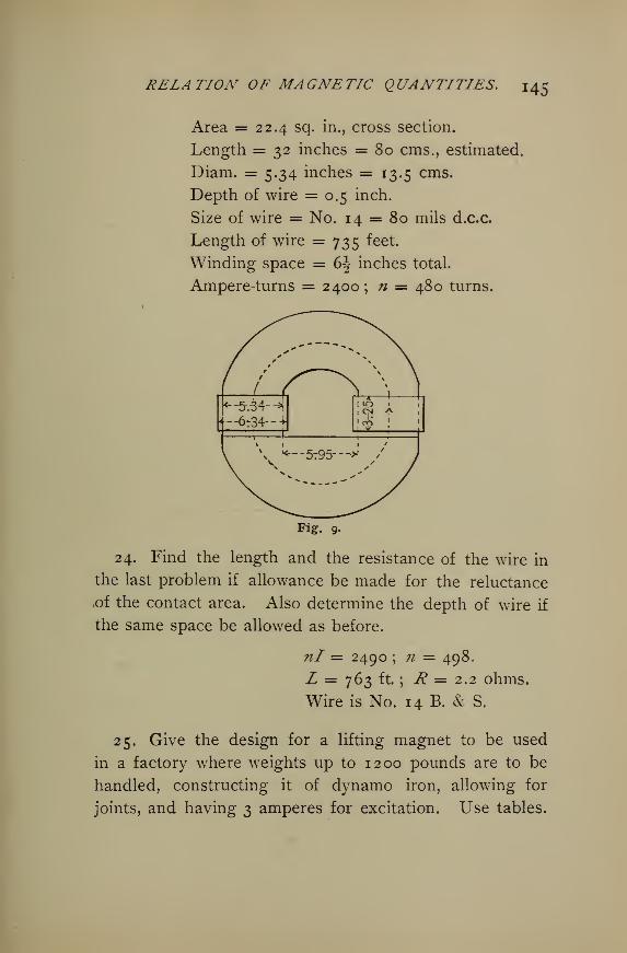
RELATION OF MAGNETIC QUANTITIES. 145
Area = 22.4 sq. in., cross section.
Length = 32 inches = 80 cms., estimated.
Diam. = 5.34 inches = 13.5 cms.
Depth of wire = 0.5 inch.
Size of wire = No. 14 = 80 mils d.c.c.
Length of wire = 735 feet.
Winding space = 6^ inches total.
Ampere-turns = 2400; n = 480 turns.
24. Find the length and the resistance of the wire in
the last problem if allowance be made for the reluctance
.of the contact area. Also determine the depth of wire if
the same space be allowed as before.
nl = 2490 ; n = 498.
L = 763 ft. ; R = 2.2 ohms.
Wire is No. 14 B. & S.
25. Give the design for a lifting magnet to be used
in a factory where weights up to 1200 pounds are to be
handled, constructing it of dynamo iron, allowing for
joints, and having 3 amperes for excitation. Use tables.
146 ELECTRICAL AND MAGNETIC CALCULATIONS.
L = 40 cm., total; L = 28 cm., horseshoe.
A — 25.8 sq. cm. == 4 sq. in.
#/= 2012 ; n = 671 ; wire = No. 16 d.c.c.
Depth = 8 layers = 0.5 in. ; space = 5.4 in.,
or 2.7 in. each side.
L of wire = 526 ft; R = 2.7 ohms; wt.
iron = 8 kilos.
26. A steel magnet immersed in an oil bath at 15 C.
at a certain distance from the magnetometer causes a
deflection of 200 mm. Assuming its temperature coeffi-
cient to be 0.00045, to what temperature must it be heated
theoretically to lose £ its magnetism ?
'= 570.5° c.
27. Find the temperature coefficient of a magnet if
when placed at a certain distance from the magnetometer,
its axis on an east and west line, it gives a deflection of
200 mm. at 20 C, but when heated to ioo° C. it pro-
duces a deflection of 192 mm.a = 0.0005.
28. How much greater is the loss in a transformer for
a frequency of 120 with an induction of 4000 gausses
made of iron such that the hysteretic constant is 21 xio~n , than in one of the same capacity and with the
same induction, for a frequency of 100, and having a
hysteretic constant of 20 x io"-11
?
Hysteresis loss first = §% of second.
29. Determine the total hysteresis loss of a transformer
in watts, its volume being 6000 cc, induction 3200
gausses, frequency 120, hysteretic constant 20 x io~u
watts per cc. per cycle.
RELATION OF MAGNETIC QUANTITIES. 1 47
VWh = 58.42 watts.
Suggestion. — log 3200 = log 100 + log 32
= 2 +1. 50515.
log* = 1.6 x 3.50515 = 5.60824.
Use in AfB1*, B16 = x = 32oo
16 = 40573°-
30. Calculate the eddy current loss in the above trans-
former, the laminae being 10 mils thick.
We= 8.85 watts.
31. With a certain exciting current this transformer
experienced an eddy current loss Qf 8 watts. What was
the intensity of induction ? B — 3043 gausses.
32. Find the total core loss in a transformer of 5000
cubic centimeters, frequency 100, induction 3000 gausses,
hysteretic constant of the iron 20 x io~n ,thickness of
plates 13 mils.
Wh— 36.59 watts.
We= 7.6 watts.
Total = 44.2 watts.
Note. Instead of the more tedious reluctance method of calcu-
lating the required ampere-turns for a magnetic circuit, as described
in this Chapter, and originally used in the solution of the problems
in this section, it will be more convenient to use the curves given on
page 229. Obtain B from the given conditions, find H correspond-
Hling from the proper curve, whence ni — = .8 HI, approximately,
1.256
where I is length in centimeters of the particular portion being cal-
culated. The total ampere-turns will tken be the sum of the several
nipartial ampere-turns. See also tables on page 298 for -=- •
I48 ELECTRICAL AND MAGNETIC CALCULATIONS.
IX.
THE E.M.F. OF DYNAMOS AND MOTORS.
44. Bipolar, Direct Current Machines.— There are
three elements on which the electromotive force of a
dynamo machine depends ; namely, the magnetic flux
through the armature, the number of armature conductors
and the speed of rotation of the armature. All this maybe summed up by saying the electromotive force depends on
the rate of change of the magneticflux through the armature
loops.
Representing the flux in maxwells by <£, the number of
armature conductors counted all the way around by n, the
speed in revolutions per second by v, the E.M.F. set up
in an armature will be, in C.G.S. units,
E = <f>nv. (78)
Or expressing E in volts the E.M.F. is
* = —>
r
(19)
Evidently any one of the four quantities in this formula
may be found when the other three are given, or when
conditions are given making it possible to determine the
other three. Thus
io8E 10 8 E io8E<j> = ; n — —-— ; v— —
nv cf>v <pv
THE E.M.F. OF DYNAMOS AND MOTORS. 149
Example. — A dynamo, drum armature, has 50 com-
mutator segments and 50 coils of wire No. 10, two turns
to each coil, which are rectangular in shape, 8" X 12";
the density of flux through the armature which runs at
2500 r.p.m. is 10,000 gausses. What E.M.F. does it
generate ?
Solution. — There are 50 X 2 = 100 turns, and since
for each coil there are two surface wires, there are
in this case 100 X 2 =200 wires, or surface conductors.
v= 2500 -j- 60 = 4if r.p.s.; <£ = 10,000 X 8 X 12 X \5- =6,000,000 maxwells approximately. Hence
_ <bnv 6 X io6 X 200 X 4itE = ^—r- = r ^-2 = COO VOltS..IO8 IO8 °
Example.— How many coils of wire of 2 turns each
would it require on this armature to generate 250 volts ?
Solution.—io 8 xE io8 X2Co
n =— = = 100 conductors.cj>v 6 x 10 x 4if
Hence there will be ±%$- =50 coils of one turn each or
25 coils of 2 turns each. It would perhaps be better to
use 50 coils of one turn each and 50 commutator bars.
Example.— If we wish to change the dynamo pulley so
as to make a 200 volt machine of it, the pulley must be
selected so as to give what speed in r.p.m. ?
Solution.—io8 X E io8 X 200
v = = = -Z7.1 r.p.s.<f>n 6x iox 100 °°^ ^
Hence the speed of the pulley should be 33^ X 60 =2000 r.p.m.
150 ELECTRICAL AND MAGNETIC CALCULATIONS.
45. Alternators. — Alternators usually have all the
armature coils connected in series instead of the two
halves in parallel as in bi-polar direct current machines.
The E.M.F. will therefore be double, other conditions
being the same. Hence a two-pole alternator would give
an E.M.F.
*-"-£ :
<s°>
If there are p pairs of poles, the rate of change of
magnetic lines will be p times as great, and
2As previously stated the average electric pressure is - =
0.636, while the effective pressure is —— = 0.707. HenceV2
the formula (81) must be increased by the ratio of
1 2these, or by —— -f- - = 1.11. We shall call this value k,
V2 *
whence _, 2 <f>nvpk ,n .
In practical machines the value of k will vary somewhat
from the theoretical value, depending on the width of
poles, pitch and nature of windings. It generally ranges
from 1 to 1.2. But there will be on the other hand a
certain amount of opposing E.M.F. in the opposite sides
of each coil because of their width, the amount depending
on the ratio of the width and pitch of poles to the width
of the coils. This tends to reduce k, so that as an
average it will not vary much from 1 . 1 1
.
THE E.M.F. OF D YNAMOS AND MO TORS. I 5 [
In alternators multiple wound the electromotive force
is reduced to that produced only by the number of coils
in series. If half are in series, then
*=*=?• (*)
It is to be observed that n is always the number of con-
ductors counted all the way round the surface of the
armature ; and <j> is the maxwells of flux out of one pole
into the armature.
We may modify (82) by substituting f, the frequency,
for the product vp to which it is equal ; and instead of
k put its value, 1.11. We then have
E^-^. (84)
If it is desired to find the flux which each pole must
carry in order to produce a certain E.M.F. at a given
frequency when the number of armature conductors is
fixed, we have from (84)
<£ = -2-
'
(85)^ 2.22 nfv 0/
For the number of armature conductors,
E X iq8 /q^n = —, • (85)2.22 <f>/
y
For the frequency from which 7/ may then be obtained,
Example. — Suppose the conductors of the two-pole
machine represented in the first, example under section
152 ELECTRICAL AND MAGNETIC CALCULATIONS.
50 were all in series and the opposite ends connected to
two rings so as to supply an alternating current. Whatwould be the E.M.F. ?
Solution.—2 d>nv 2 X (6x io6
) X 200 X 41I-E =a = - '—=. 2- = IOOO VOltS.
IO8 IO8
Example. — Determine the electromotive force of a
6-pole alternator running at 2100 r.p.m., the flux being
24 x io5 maxwells and there being 200 wires on the
armature.
Solution.—2 $nvpk _ 2 X 24 X io5 X 200 X 35 X 3 X 1.1
1
io8 io8
= 1 1 18.8 volts.
Example.— What must be the number of maxwells of
flux furnished by each pole of a machine similar to the
last for 560 volts, and what cross section of poles ? Also
what width of poles to be equal to one-half the pitch?
Solution.—Ex io8 560 X io8
„d> = = =1,201,200 maxwells,
2.22 nf 2.22 x 200 X 3 X 35
For dynamo poles B may be, say 12,000 gausses.
Hence<f> 1,201,200
A = -£ = — = 100 sq. cm.B 12,000
The circumference of the pole circle is very nearly
80 cms. Since there are 6 poles and the distance apart
is equal to the width, each must be8o-j- 12 = 6.66 cms.
THE E.M.F. OF DYNAMOS AND MOTORS. 1 53
The length of pole face and armature core must then be
ioo-i- 6.66 =15 centimeters.
46. Multipolar Direct Current Dynamos. — The usual
method of winding Gramme ring armatures is to wind
the different coils the same way continuously around the
ring. Now when the coils are joined together, the end of
the first may be joined to the beginning of the second,
the end of the second to the beginning of the third, etc.
There will then be as many brushes and as many arma-
ture circuits as poles. This is called the multiple wind-
ing. Thus a 4-pole machine requires 4 brushes— two
pairs at right angles, and 4 circuits in the armature all in
parallel. Evidently the brushes of like polarity may be
connected together, thus putting all the current in a single
external circuit. Also the coils may be so cross connected
at the commutator end of the armature as to require but
two brushes set at an angular distance apart equal to the
pole pitch. The E.M.F. of such an armature is
*-£ .«As before, <£ is the maxwells of armature flux from each
pole, n the number of armature conductors counted all
the way around, and v the speed in r.p.s.
On the other hand the coils may be joined by connect-
ing the end of the first to the end of the second, the
beginning of the second to the beginning of the third,
the end of the third to the end of the fourth, the begin-
ning of the fourth to the beginning of the next, etc. In
a 4-pole and 4-coil machine, the beginning of the fourth
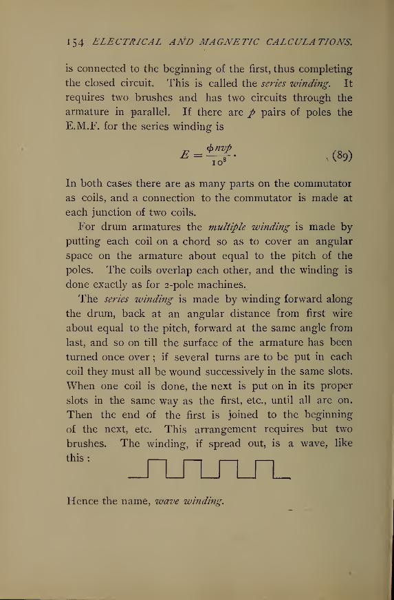
154 ELECTRICAL AND MAGNETIC CALCULATIONS.
is connected to the beginning of the first, thus completing
the closed circuit. This is called the series winding. It
requires two brushes and has two circuits through the
armature in parallel. If there are p pairs of poles the
E.M.F. for the series winding is
In both cases there are as many parts on the commutator
as coils, and a connection to the commutator is made at
each junction of two coils.
For drum armatures the multiple winding is made by
putting each coil on a chord so as to cover an angular
space on the armature about equal to the pitch of the
poles. The coils overlap each other, and the winding is
done exactly as for 2-pole machines.
The series winding is made by winding forward along
the drum, back at an angular distance from first wire
about equal to the pitch, forward at the same angle from
last, and so on till the surface of the armature has been
turned once over ; if several turns are to be put in each
coil they must all be wound successively in the same slots.
When one coil is done, the next is put on in its proper
slots in the same way as the first, etc., until all are on.
Then the end of the first is joined to the beginning
of the next, etc. This arrangement requires but two
brushes. The winding, if spread out, is a wave, like
,his: J^ru^_n_Hence the name, wave winding.
THE E.M.F. OF DYNAMOS AND MOTORS. 155
The same formulae (&&) and (89) apply to the mul-
tiple and series, respectively.
When the number of pairs of poles is even, the two
brushes in the series winding will be at an angular dis-
tance apart equal to the pole pitch. If the number of
pairs be odd, however, the brushes will be diametrically
opposite.
Example.— Two drum armatures for 6-pole machines
are exactly alike, except one is multiple wound, while the
other is series. The following constants are known
:
Flux 6 X io6 maxwells ; surface conductors 500 ; speed 20
r.p.s. Determine their respective E.M.F.'s.
Solution.— For the multiple wound,
^ <bnv 6 X io6 X coo X20 ,£ = ?— = g = 600 volts.IO8 IO8
For the series wound,
_ <bnvp 6Xio6 X cooX 20X ^E = ?—?- = ?—, 3 = 1800 volts.IO IO8
Example. — What will be their respective resistances
and current capacities ?
Solution. — If wound with wire of the same size the
multiple wound can carry 3 times as much current as the
series wound, because with 6 brushes and 6 circuits in
parallel, each circuit carries 1 of the total output in
amperes. On the other hand, the series wound armature
has 2 circuits in parallel, each carrying \ of the total
current in amperes. Hence the former can carry 3 times
I56 ELECTRICAL AND MAGNETIC CALCULATIONS.
as much as the latter. The output in watts is the same in
both cases.
The resistance of the multiple wound will be, for the
reasons just stated, \ of that of the series winding. The
latter has \ the resistance of all its armature wire, since
two halves of it are in parallel. The former has 3^the resistance of all its wire, since its 6 sixths are in
parallel.
Example.— A machine is required to give 560 volts
and to run at a speed of 1800 r.p.m. Suppose it is built
with 6 poles, what area must each pole face present to
the air gap, not allowing for leakage ?
Solution. — From (89)
E x io8
<f> = .
nvp
Assuming 400 armature conductors series wound,
560 X io8_ „
<£> = — = ic.cc x io6 maxwells.400 X 30 x 3
° o:>
then A = -±-±z . = 1000 sq. cms.
Allow B = 15,550 gausses,
15-55 X iof
15.55 X 1Qi
Example.— What will be the diameter of the armature
if the pole face may be taken 2\ times as long as wide,
the pole width being equal to one-half the pitch ?
Solution.— The width of the pole face is
Viooo -5- 2.5 = 2 ° cm «
The length of the face is
1000 -7- 20 = 50 cm.
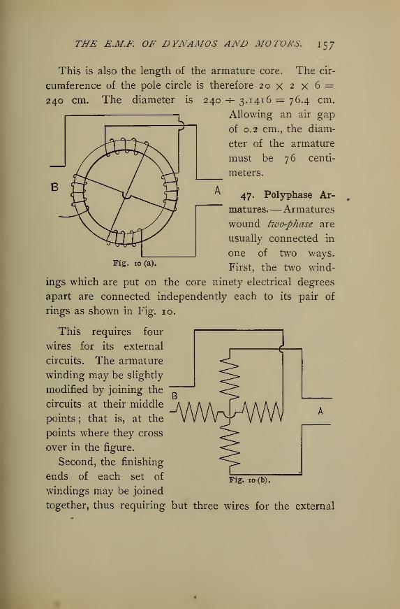
THE E.M.F. OF DYNAMOS AND MOTORS. 157
This is also the length of the armature core. The cir-
cumference of the pole circle is therefore 20 x 2 x 6 =240 cm
Fig. 10 (a).
-s- 3.1416 = 76.4 cm.
Allowing an air gap
of 0.2 cm., the diam-
eter of the armature
must be 76 centi-
meters.
47. Polyphase Ar-
matures.—Armatures
wound two-phase are
usually connected in
one of two ways.
First, the two wind-
ings which are put on the core ninety electrical degrees
apart are connected independently each to its pair of
rings as shown in Fig. 10.
jwvmv^
This requires four
wires for its external
circuits. The armature
winding may be slightly
modified by joining the
circuits at their middle
points ; that is, at the
points where they cross
over in the figure.
Second, the finishing
ends of each set of
windings may be joined
together, thus requiring but three wires for the external
Fig. 10(b),
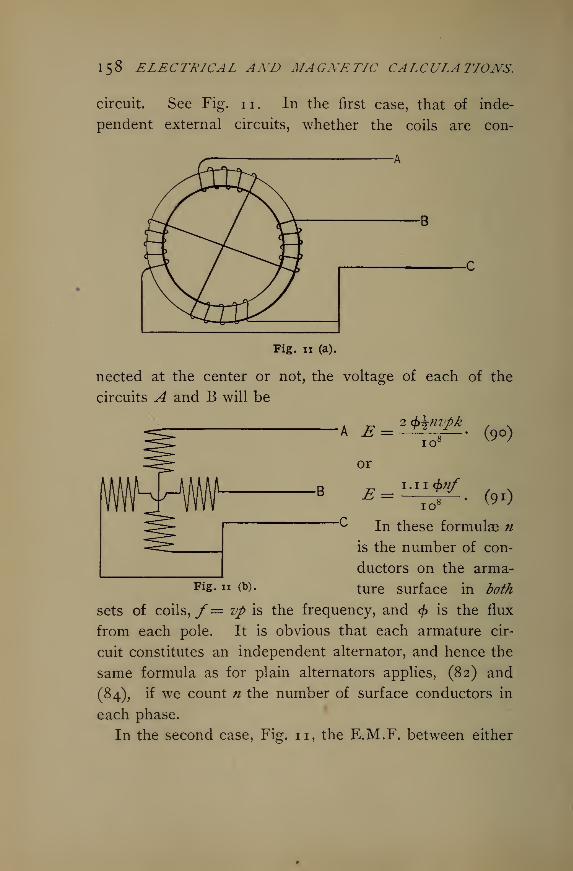
158 ELECTRICAL AND MAGNETIC CALCULATIONS.
circuit. See Fig. 11. In the first case, that of inde-
pendent external circuits, whether the coils are con-
Fig, n (a).
nected at the center or not, the voltage of each of the
circuits A and B will be
E =
or
2 $\nvpk
io c
n<t>nf
io (
(9o)
(9i)
In these formulae n
is the number of con-
ductors on the arma-Fi«- IT <*>• ture surface in both
sets of coils, /= vp is the frequency, and <£ is the flux
from each pole. It is obvious that each armature cir-
cuit constitutes an independent alternator, and hence the
same formula as for plain alternators applies, (82) and
(84), if we count n the number of surface conductors in
each phase.
In the second case, Fig. 11, the E.M.F. between either
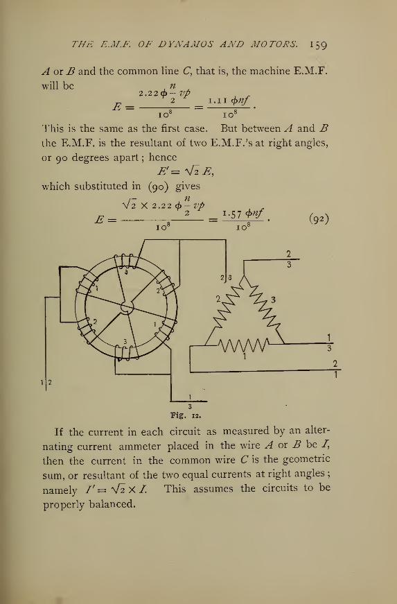
THE E.M.F. OF DYNAMOS AND MOTORS. 1 59
A or B and the common line C, that is, the machine E.M.F.
will be n
E =2.2 2(f)- Vp
2 1.1 1 <$>nf
10 10"
This is the same as the first case. But between A and Bthe E.M.F. is the resultant of two E.M.F.'s at right angles,
or 90 degrees apart; hence
£'= V2E,which substituted in (90) gives
/-,n
V2 X 2.22 d>-7Jfi ,.
e = .
2 = l
-^tnf - (92)io l IO l
Fig. 12.
If the current in each circuit as measured by an alter-
nating current ammeter placed in the wire A or B be /,
then the current in the common wire C is the geometric
sum, or resultant of the two equal currents at right angles;
namely /'= V2 X L This assumes the circuits to be
properly balanced.
l6o ELECTRICAL AND MAGNETIC CALCULATIONS.
Armatures wound three-phase are also usually connected
in one of two ways. First, the coils for each of the
three phases are put on 120 electrical degrees apart,
and connected as shown in Fig. 12, 1 to 2, 2 to 3,
1 to 3.
This is the mesh arrangement, requires 3 rings, 3 wires
for the external circuit, and gives an E.M.F. between any
two wires which is equal to the E.M.F. set up in each
phase. This is
2.22 9-/
This may be written
0.74 <£/*/*£ =io c
n is the number of surface conductors counted in all the
phases, and f = vp, as before. The current in any line
wire is V3 times the current in any one-phase winding
in the armature. If /' be the current in coil 1, the cur-
rent measured by an amperemeter in any line will be
f=^f'=I.732l'. (94)
This relation comes from the fact that the line current is
the resultant of two equal armature currents 120 degrees
apart ; that is, it is the third side of an isosceles triangle
opposite the angle of 120 . Hence it is V3 times each
of the two equal sides.
Second, one end of each winding is connected to a
common junction, the other ends being joined respec-
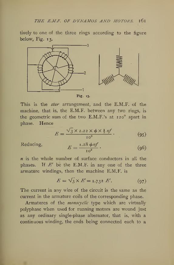
THE E.M.F. OF DYNAMOS AND MOTORS. l6l
tively to one of the three rings according to the figure
below, Fig. 13.
Fig. 13.
This is the star arrangement, and the E.M.F. of the
machine, that is, the E.M.F. between any two rings, is
the geometric sum of the two E.M.F.'s at 120 apart in
phase. Hence
V3 X 2.22 X cf>X \nfE =
Reducing, E
io°
1.28 <f>nf
7tf~
(95)
(96)
n is the whole number of surface conductors in all the
phases. If Er be the E.M.F. in any one of the three
armature windings, then the machine E.M.F. is
E=\[^XE'=i. 732E'. (97)
The current in any wire of the circuit is the same as the
current in the armature coils of the corresponding phase.
Armatures of the monocyclic type which are virtually
polyphase when used for running motors are wound just
as any ordinary single-phase alternator, that is, with a
continuous winding, the ends being connected each to a
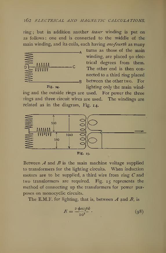
1 62 ELECTRICAL AND MAGNETIC CALCULATIONS.
ring ; but in addition another teaser winding is put on
as follows : one end is connected to the middle of the
main winding, and its coils, each having one-fourth as many-
turns as those of the main
winding, are placed 90 elec-
trical degrees from them.
The other end is then con-
nected to a third ring placed
between the other two. For
lighting only the main wind-
ing and the outside rings are used. For power the three
rings and three circuit wires are used. The windings are
related as in the diagram, Fig. 14.
Fig. 15.
Between A and B is the main machine voltage supplied
to transformers for the lighting circuits. When induction
motors are to be supplied, a third wire from ring C and
two transformers are required. Fig. 15 represents the
method of connecting up the transformers for power pur-
poses on monocyclic circuits.
The E.M.F. for lighting, that is, between A and B, is
E = 2 $nvpk
io c (98)
THE E.M.F. OF DYNAMOS AND MOTORS. 1 63
The E.M.F. between A and C or B and C is the re-
sultant of two E.M.F. 's at right angles, one being \ of the
other; or one is \ of the total voltage, the other \.
Hence between the middle ring and either outside ring
the E.M.F. is
V(i)2 + (i)2 = 0.56 of the main E.M.F.
Therefore the formula for this is
1. 12 <f>?izpk , s£ = —TJ (99)
n is the number of surface conductors in the main
winding.
If the main E.M.F. is 1040 volts, the E.M.F. between
the middle ring and either outside one is 0.56 x 1040 = 580
volts. It is recommended that the transformers for the
induction motors be 9 to 1 or 4 to 1 , instead of 1 o to 1 or
5 to 1, so as to give a higher voltage at the motor termi-
nals to allow for the inductive drop in the motors. If the
transformers are connected as indicated, the three second-
ary voltages are approximately equal.
Example.— A two-phase ring armature with independent
circuits is to be constructed for 520 volts at a frequency
of 125. How many turns of wire are necessary for each
phase when the flux from each pole is io6 maxwells?
1 . 1 1 <f>nfSolution. — Since E =
io 8
£X io 8 C20 X io 8P
n = — = ^ = ^72 surface wires.I.IKjA I.HXIOb Xl25
Since each phase contains one-half of the total, each will
require 1 of 372 =186 conductors.
1 64 ELECTRICAL AND MAGNETIC CALCULATIONS
Example.— Suppose the same voltage is required in a
two-phase machine for three-wire circuits. How many con-
ductors would be necessary ?
Solution.— Since the machine voltage, that is, the
E.M.F. between either outside wire and the commonmiddle wire, must be 520 volts, the same as before, each
phase winding must give 520 volts, as before. Hence
the same number of turns is required as in the last
example. But the voltage measured between the two
outside mains will be
VS20 x 2 = ^J/ = 73s volts.
Example.— Let it be required to wind the armature
for three-phase currents, delta, or mesh winding. Howmany turns will be required in each phase ? Also for a
line current of 20 amperes primary, how many amperes
will flow in the armature winding?
Solution.— For 3-phase mesh
0.74^/z/m
whence
108
jEXio8 520X108
n = J> = e = 558 -
0.74 4>f o.74xio6 xi25
Therefore each phase requires i of 558 = 186 wires.
Also armature current = line current -* V3. Then
_, I 20I = —— = ==11.5 amperes.
V3 I -73 2
THE E.M.F. OF DYNAMOS AND MOTORS. 1 65
Example.— A similar machine is to be wound 3-phase,
star connected. How many turns are required in each
phase ?
Solution.— Referring to the figure given, it is appar-
ent that each phase must generate the required line
E.M.F. *- Vi ; or E' = —-= = -^- = 300 volts.
V3 !-732
Hence 300 Xio8
# = —~ « = 3 2 4,0.74X io6 X 125
and ^ n = 108 wires in each phase.
Example.— How many turns must be put in the main
winding of a monocyclic generator for an E.M.F. of 2080
volts, assuming </> to be 2 x io6 maxwells andy= 125
cycles ; also how many in the teaser winding so that the
primary E.M.F. between the outside mains and the teaser
line shall be 1100 volts ?
Solution.— From (98) the main E.M.F. is
2.22 <f>?if& = -„—;
IO8
hence ^Xio8. 2080X10 8
n = —= = — = = 374.2.22 4>f 4.44 x iob x 125
Also, since the primary voltage for motors is to be 1100,
the E.M.F. for teaser coils must be
J2t =y noo2 -f^-^j = 358 volts
Therefore
358 X io 8
2.22 X 2 X 10 X 125= 64 wires.
1 66 ELECTRICAL AND MAGNETIC CALCULATIONS.
48. Original Problems.— 1. What flux will a two-pole
direct current drum type machine be required to supply
for 220-volt lamps, say a 240-volt machine running at 1500
r.p.m. when there are to be 100 coils of 2 turns each on
the armature? = 2.4 x io6 maxwells.
2. The following data are taken from a small Westing-
house bipolar incandescent dynamo. Armature body 8^-
inches x 8 inches, 100 grooves, two wires per groove.
Normal speed 2100 r.p.m. It is also determined that the
armature flux is 1,671,000 maxwells at full load. Whatshould be the voltage of the machine under load when
running at normal speed ? E = 117 volts.
3. A T.-H. incandescent dynamo, motor type 3 D,
capacity 3000 watts, furnishes the following data. There
are 64 coils on the armature, 3 turns per coil ; speed
2400 r.p.m., E.M.F. at 20J amperes, 116 volts. Whatshould be the armature flux under the conditions of load
named ? <£= 755,208 maxwells.
4. How many maxwells are due to the compounding
when the above machine tests no volts on open circuit?
Approximately,<f)c= 39,062 maxwells.
5. The pulley on the machine mentioned in problem 2
has a diameter of 6 inches. At what speed must the
machine run and how large a pulley will be required to
give 120 volts, when the engine to which it is belted has
a pulley 36 inches in diameter running at 350 r.p.m. ?
Speed = 2154 r.p.m.
Pulley = 5.85" diameter.
THE E.M.F. OF DYNAMOS AND MOTORS. 1 67
6. Suppose the armature in problem 3 is to be rewound
for 125 volts, using the same fields but changing the com-
mutator if necessary and running at the same speed as
before. How many turns per coil will be necessary ?
n = 414 wires = 208 turns.
Hence use 52 segments on commu-
tator, and wind 4 turns to each coil.
7. The following data are known about a certain
Westinghouse pony alternator. Speed 2000 r.p.m.
E.M.F. 50 volts. There are 8 poles and 6 turns per
coil on the armature. If we may assume the average
constants to apply, what must be the flux from each
pole? <£ = 176,000 maxwells.
8. An 8-pole alternator is rated at 1500 r.p.m. There
are 12 turns per coil. If an estimate places the flux at
2,440,000 maxwells, what voltage should the machine give ?
E = 1040 volts.
9. What will be the size of armature in the machine
in problem 8 if y1^ inch is allowed for clearance, and the
pole width is one half the pitch, not considering any
leakage, assuming B = 10,000 gausses ?
Length = 9" = 22.8 cms.
Pole width = 4.2"= 10.7 cms.
Pitch circle = (8 x 10.7) X 2 = 17 1.2 cms.
Diameter = 171.2 -r- 7r = 54.5 cms.
Armature diameter = 54 cms.
1 o. How many poles will be required in an alternator for
a voltage of 1040, surface conductors 200, flux 2,342,000
maxwells, speed 1200? Find frequency, p = 5 pairs*
/= 100.
1 68 ELECTRICAL AND MAGNETIC CALCULATIONS.
ii. What flux will be required by a drum armature
wound for 6 poles, direct current, 240 volts, 1200 r.p.m.,
multiple connected, n = 360 ? cj> = 3,333,000 maxwells.
12. What E.M.F. would this last machine give if the
armature circuits were series connected ?
E = 720 volts.
13. A 4-pole direct current dynamo is built for 120
volts under load. How many wires must be connected
on the drum for a speed of 1200 r.p.m., multiple circuit
armature, flux 3 x io6 maxwells ? n = 200 conductors.
14. A half horse-power motor, 4 poles, is to be built
to run at 2400 r.p.m., series connected. It is calculated
that the polar faces are to be i;/
x 4". The E.M.F. is
to be 112 volts. A density of flux in the air gaps is
assumed to be 10,000 gausses. How many turns per
coil must be wound on the drum, for a 24-coil armature ?
n = 560 wires = 24 per coil.
15. What flux must be sent into a 2-phase armature
having 200 wires in each phase for an E.M.F. of 1040
volts, the machine being 12-pole and running at 900
r.p.m., connected for 4-wire circuits ?
<£ = 2.6 x io6 maxwells.
16. What would be the required magnetization for a
voltage of 520 when the windings are connected for a two-
phase, 3-wire circuit, other conditions the same as in 15 ?
Also what is the frequency? What speed would give
a frequency of 120? <£ = 1.3 x io6 maxwells.
/=9°-v = 1200 r.p.m. for 120 cycles.
THE E.M.F. OF DYNAMOS AND MOTORS. 1 69
17. How many turns must be wound in each phase of
a two-phase alternator having ten poles, for 2080 volts,
for a frequency of 60 and an estimated flux of 12 x io6
maxwells, circuits to be 3-wire ? What is the speed ?
n, each phase, = 130.
Speed = 720 r.p.m.
18. How much current must each phase winding be
capable of carrying in problems 16 and 17, when it is
desired that the wattmeter in the circuit read 50 K.W.
full load in each case ?
Effective line current in 16 = 96 amperes.
Total =192.Effective line current in 17 = 24 amperes.
Total = 48.
19. What is the E.M.F. between the outside wires in
the machine described in problem 17?
E = 2941.5 volts.
20. What should be the E.M.F. of the following 3-
phase, star connected alternator? Normal speed 1000
r.p.m., 12 poles, 560 conductors each phase, flux from
each pole 804,000 maxwells. Also what is the frequency ?
E.M.F. = 1729 volts.
f= 100.
21. A 3-phase mesh connected alternator having ten
poles, running at 720 r.p.m., flux 7,600,000 maxwells, has
a capacity of 250 K.W. What is the brush E.M.F., and
the current in each phase winding, the total surface con-
ductors being 600 ? E = 2025 volts.
/= 41 amperes per phase.
\yo ELECTRICAL AND MAGNETIC CALCULATIONS.
22. Let the armature in 21 be star connected. Howwill the E.M.F. and current differ from those just
obtained? E.M.F. = 3502 volts.
/= 41 amperes per phase.
23. Find the flux and the current per coil for a 3-
phase machine, first when star connected, second when
mesh connected, having given the following data. Sur-
face conductors 864, poles 8, speed 900 r.p.m., brush
E.M.F. 2500 volts, capacity 120 K.W.
Star, cj> = 3.7 x 1 o6 maxwells.
/= 28 amperes.
Mesh,<f>= 6.5 x 10⁶ maxwells.
/= 16 amperes.
24. How many turns must be put in the main winding
of a monocyclic generator,/= 60, p — 5, <j> = 5 x 10⁶,
E = 1080, capacity =150 K.W. ? Also if the teaser
winding has just \ as many turns, how many volts should
be measured between the main and teaser line wires ?
What is the effective current and the speed ?
// = 10 coils, 8 turns each.
E.M.F. for motors = 605 volts.
/= 140 amp. ; speed 720 r.p.m.
25. What flux must be provided for a monocyclic
machine for 2160 volts, 10 poles,/= 60, main winding
= 200 conductors? What is the current capacity of the
wire when the machine is rated at 200 K.W? Also
what should be the speed?<f>= 8,108,100 maxwells.
/= 92.6 amperes.
v == 720 r.p.m.
CALCULATION OF FIELDS. I J
I
X.
CALCULATION OF FIELDS.
49. Two-Pole Continuous Current Machines. — We are
now to apply to dynamos the principles of magnetic cir-
cuits which were worked out in a previous chapter.
However, there are some practical details in connection
with dynamo fields which it will be well to keep in mind
in determining magnetomotive forces. The following
examples will show that there are several parts in the
magnetic circuit, — field cores, yoke, two air gaps, and
armature core. Account must be taken of the flux den-
sity, length and cross section of each part. From these
reluctances are found which multiplied by the total flux in
each part gives the M.M.F. required for each portion of
the circuit.
Example. — A bipolar, drum armature, direct current
machine requires 6 x io 6 maxwells of flux. The armature
core is 8" x 12". The air gaps including clearance and
copper and insulation are each 1 centimeter in length.
The poles are separated above and below the armature
4 inches. The field cores are 11" in diameter and 15"
long. Polar heads, that is, the portion above the wind-
ing, average 8 inches in length of flux. The yoke
between core centers is 20" and has a cross section of
100 square inches. The leakage coefficient is assumed
to be 1.3. Determine the separate reluctances, the
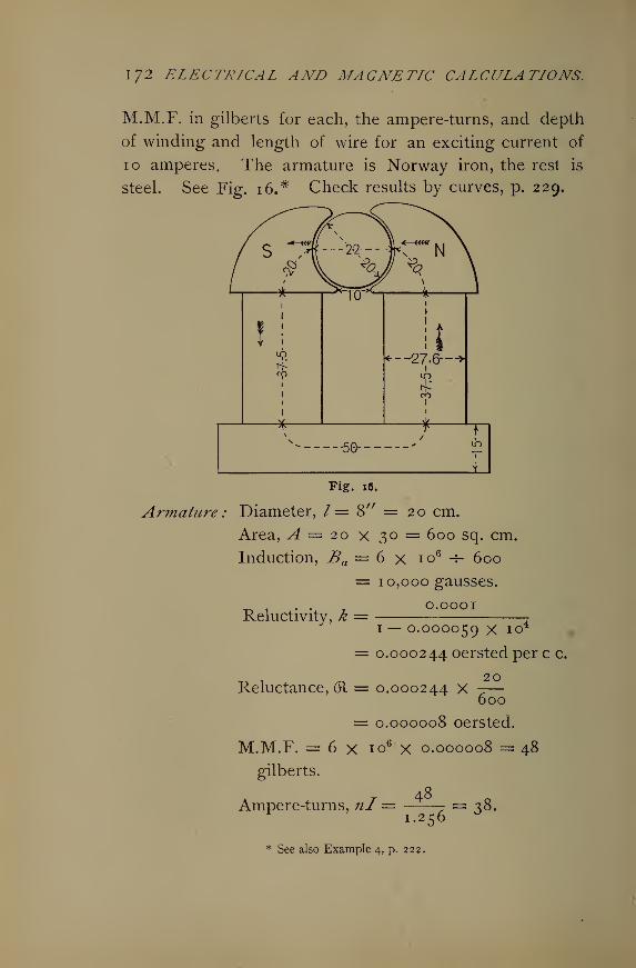
172 ELECTRICAL AND MAGNETIC CALCULATIONS.
M.M.F. in gilberts for each, the ampere-turns, and depth
of winding and length of wire for an exciting current of
10 amperes. The armature is Norway iron, the rest is
steel. See Fig. i6.# Check results by curves, p. 229.
Armature
1
—
*—
1
-TO*- *1
1
1
! ! it19
CO1
1
1
<-- J27.6—
*
1
CO1
---50--- - ip
1
Fig. 16.
Diameter, /= 8" = 20 cm.
Area, A = 20 x 30 = 600 sq. cm.
Induction, Ba = 6 x io6 ^ 600
= 10,000 gausses.
O.OOOIReluctivity, k =
1 — 0.000059 X io4
= 0.000244 oersted per c c.
20Reluctance, (R = 0.000244 x
600
= 0.000008 oersted.
M.M.F. = 6 x io6 x 0.000008 = 48
gilberts.
48Ampere-turns, nl —
1.256
* See also Example 4, p. 222.
= 38.
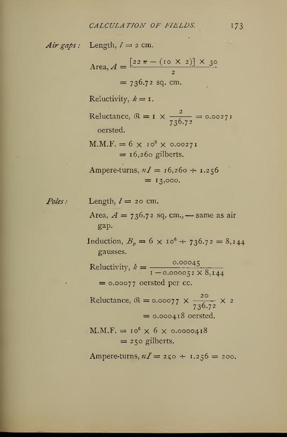
CALCULATION OF FIELDS. 1 73
Air gaps : Length, / = 2 cm.
[22 71-— (iO X 2)1 X ^OArea, A = = * JJ ^-
2
=3 736.72 sq. cm.
Reluctivity, k = 1
.
2Reluctance, (ft = 1 X —7— = 0.00271
736.72oersted.
M.M.F. = 6 x io6 x 0.00271
= 16,260 gilberts.
Ampere-turns, nl' = 16,260 -5- 1.256
= 13,000.
Poles
:
Length, / = 20 cm.
Area, ^ = 736.72 sq. cm.,— same as air
gap.
Induction, Bp = 6 x io6-r- 736.72 =8,144
gausses.
^ , . . , 0.00041;Reluctivity, k = -^—
1 — 0.00005 1 X 0,144
= 0.00077 oersted per cc.
_ •
_ 20Reluctance, 61 = 0.00077 x —7— X 2
736.72
= 0.000418 oersted.
M.M.F. = io6 x 6 x 0.0000418
= 250 gilberts.
Ampere-turns, nl = 2.^0 ~- 1.256 = 200,
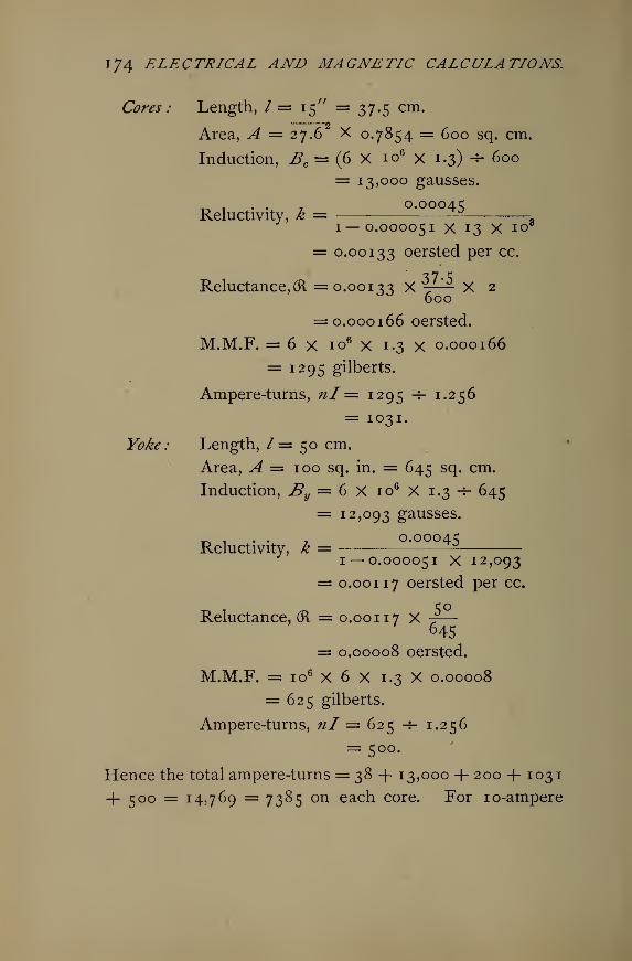
174 ELECTRICAL AND MAGNETIC CALCULATIONS,
Cores: Length, /= 15" = 37.5 cm.2
Area, A = 27.6 X 0.7854 = 600 sq. cm.
Induction, Bc= (6 X io6 x 1.3) + 600
= 13,000 gausses.
Reluctivity, k = 0.00045ft1— 0.000051 x 13 X io8
= 0.00133 oersted per cc.
Reluctance, (ft =0.00133 x 7^ X 2600
= 0.000166 oersted.
M.M.F. = 6 x io6 x 1.3 X 0.000166
= 1295 gilberts.
Ampere-turns, nl' = 1295 -5- 1.256
= 1031.
Yoke: Length, /= 50 cm.
Area, A = 100 sq. in. = 645 sq. cm.
Induction, By= 6 X io6 X 1.3 -*- 645
= 12,093 gausses.
0.00045Reluctivity, k =
1 — 0.000051 X 12,093
= 0.00117 oersted per cc.
Reluctance, (R = 0.00117 X -?
—
645
= 0.00008 oersted.
M.M.F. = io6 X 6 X 1.3 X 0.00008
= 625 gilberts.
Ampere-turns, nl = 625 -f- 1.256
= 500.
Hence the total ampere-turns = 38 + 13,000 + 200 + 103
1
4- 500 = 14,769 = 7385 on each core. For 10-ampere
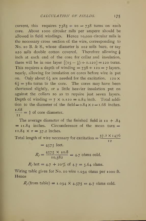
CALCULATION OF FIELDS. I 75
current, this requires 7385 -f- 10 = 738 turns on each
core. About 1000 circular mils per ampere should be
allowed in field windings. Hence 10,000 circular mils is
the necessary cross section of the wire, corresponding to
No. 10 B. & S., whose diameter is 102 mils bare, or say
120 mils double cotton covered. Therefore allowing £inch at each end of the core for collar and insulation,
there will be in one layer [(15 — ^) -f- 0.120] =120 turns.
This requires a depth of winding = 738 -s- 120 = 7 layers,
nearly, allowing for insulation on cores before wire is put
on. Only about 6^ are needed for the excitation. 120 x
6^ = 780 turns to the core. The cores may have been
shortened slightly, or a little heavier insulation put on
against the collars so as to require just seven layers.
Depth of winding =7X0. 120 = 0.84 inch. Total addi-
tion to the diameter of the field= o.84X 2 = 1.68 inches.
1.68 _ := A or core diameter.11
The average diameter of the finished field is 11 + .84
= 11.84 inches. Circumference of the mean turn =11.84 X 7r = 37.2 inches.
Total length of wire necessary for excitation =— ^—
= 4575 fee*.
4575 X IO -8Rf = 321^— = 4#7 hms cold.10,382
J?f hot = 4.7 + 20% of 4.7 = 5.64 ohms.
Wiring table gives for No. 10 wire 1.034 ohms per 1000 ft.
Hence
ify (from table) = 1.034 x 4.575 = 4.7 ohms cold.
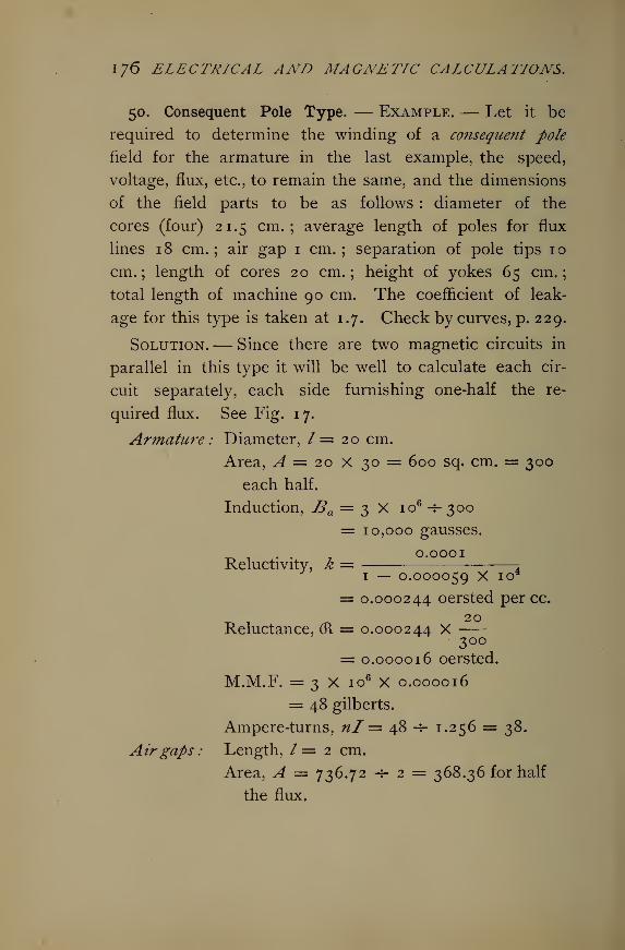
176 ELECTRICAL AND MAGNETIC CALCULATIONS.
50. Consequent Pole Type. — Example. — Let it be
required to determine the winding of a consequent pole
field for the armature in the last example, the speed,
voltage, flux, etc., to remain the same, and the dimensions
of the field parts to be as follows : diameter of the
cores (four) 21.5 cm.; average length of poles for flux
lines 1 8 cm. ; air gap 1 cm. ; separation of pole tips 1 o
cm.; length of cores 20 cm.; height of yokes 65 cm.;
total length of machine 90 cm. The coefficient of leak-
age for this type is taken at 1.7. Check by curves, p. 229.
Solution.— Since there are two magnetic circuits in
parallel in this type it will be well to calculate each cir-
cuit separately, each side furnishing one-half the re-
quired flux. See Fig. 17.
Armature: Diameter, /= 20 cm.
Area, A — 20 X 30 = 600 sq. cm. = 300
each half.
Induction, Ba — 3 X io6 -r 300
= 10,000 gausses.
^ 1 . . 70.0001
Reluctivity, k = 21 — 0.000059 x IO
= 0.000244 oersted percc.
20Reluctance, 61 = 0.000244 X
300= 0.000016 oersted.
M.M.F. = 3 X io6 X 0.000016
= 48 gilberts.
Ampere-turns, nl = 48 -4- 1.256 = 38.
Airgaps : Length, /= 2 cm.
Area, A = 736.72 -5- 2 = 368.36 for half
the flux.
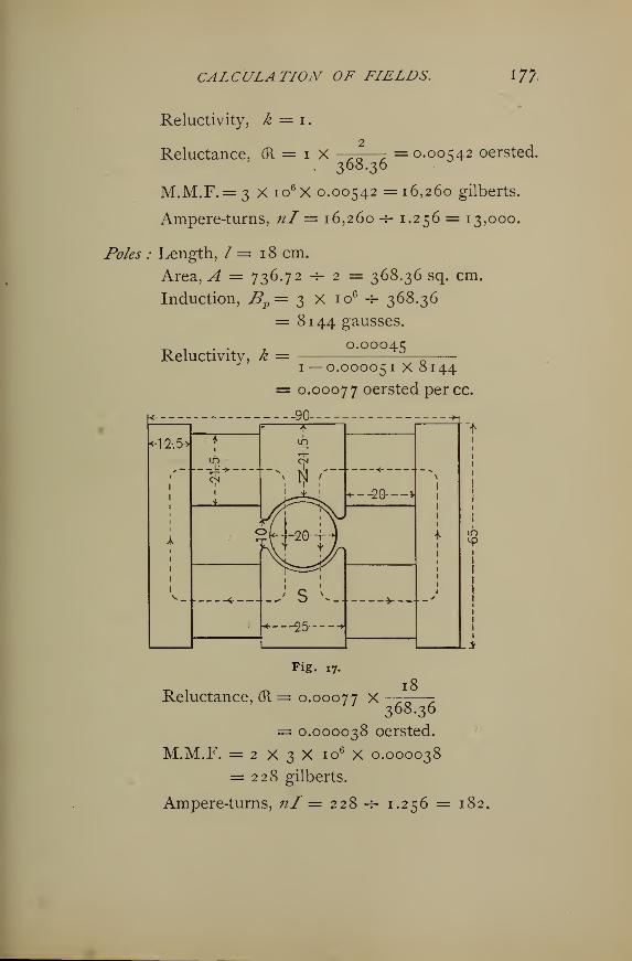
CALCULATION OF FIELDS. 17?
Reluctivity, k = 1.
Reluctance, (R=iX = 0.00542 oersted.368.36
M.M.F. = 3 X io6 X 0.00542 = 16,260 gilberts.
Ampere-turns, nl'= 16,260 h- 1.256 == 13,000,
Poles : Length, / = 18 cm.
Area, A = 736.72 -5- 2 = 368.36 sq. cm.
Induction, Bp= 3 X io6
-r- 368.36
= 8144 gausses.
0.00045Reluctivity, k =
1 — 0.000051 x 8144= 0.00077 oersted per cc.
...90
*1-2-.5*
* f11
"?• *F1
1
* — — _U->CN
-\iji r-
<-\
|i
i
1
1
i
1
1
1
*«.—20— >
1
1
1
1
1
*1
1
1
1
1
C
!
1
t
1
1
<r J S v- ^1
\
1
t
i
1
\
Fig. 17.
Reluctance, (R = 0.00077 X —77;
—
-z
368.36
= 0.000038 oersted.
M.M.F. = 2 X 3 X io6 X 0.000038
= 228 gilberts.
Ampere-turnS, /z/ = 22 8 -T- I.2C;6 = l82
178 ELECTRICAL AND MAGNETIC CALCULATIONS.
Cores : Length, / = 20 cm.
Area, A = 21.5 X 0.7854 = 363 sq. cm.
Induction, Bc — 3 X io6 X 1.7 -5- 363= 14,060 gausses.
^ , . . , 0.0004cReluctivity, k = — —
1—0.000051X14,000= 0.00159 oersted per cc.
_ , _. 20Reluctance, (R = o.ooico X -7- X 2
= 0.0001752 oersted.
M.M.F. = 3 X io6 X 1.7 X 0.0001752
= 894 gilberts.
Ampere-turns, nl= 894 -*- 1.256 = 712.
Yoke : Length, / = 42 cm. for lines of force.
Area, A = \2\ X 30 = 375 sq. cm.
Induction, By= 3 X io6 X 1.7 -s- 375= 13,600 gausses.
-r. 1 • • t 0.0004cReluctivity, k ~
1 — 0.000051 x 13,600
0.00115 oersted.
42Reluctance, (R = 0.00 1 1 c X3
375= 0.000128 oersted.
M.M.F. = 3 x io6 X 1.7 X 0.000128
= 652 gilberts.
Ampere-turns, nl= 652 -5- 1.256 == 519.
Hence the total ampere-turns for each circuit = ^8
+ 13,000 + 182 + 712 + 519 = 14,451. Total reluctance
two paths in parallel, 0.005777 -5- 2 = 0.002888 oersted.
The total M.M.F. for each circuit = 18,151 gilberts.
CALCULATION OF FIELDS. I 79
The machine will require on each of the four cores \ of
14,451 =7226 ampere-turns. If we connect all the field
coils in series, the wire will be of the same size as in last
example, namely No. 10 B. & S. = 120 mils d.c.c. Al-
lowing 1 centimeter for collars and insulation on each
core, we have 19 cm. for wire = 7.5 inches, nearly. In
one layer there will be 7.5 -s- 0.120 = 62 turns which will
require 722.6 -5- 62 = 12 layers approximately, making a
i-44
8.6depth of winding 0.120 X 12 = 1.44 inches = 2 x
= \ of core diameter.
Mean length of one turn = — —— = 2.7 feet.
Total length of No. 10 wire for fields = (2.7 x 744) X
4 = 8035 feet. Total weight (32 lbs. per 1000 feet, ap-
proximately) = 8.035 * 3 2 = 2 57 ^s.
Resistance of field winding
8035 X 10.8,Rf = ———- = S.z ohms cold
;
8.3 + 20% of 8.^ = 9.96 ohms hot.
Drop in field winding = 9.96 X 10 = 99.6 volts.
Suppose now we wind the two halves for 5 amperes
each and connect them in parallel. Each spool will re-
quire 7226 -7- 5 = 1445 turns of 5000 circular mils each
cross section. This corresponds to No. 14 B. & S. = 64
mils bare, or about 80 mils d.c.c. In one layer there
will be 100 turns, and 14 layers deep = 14 X 0.08 = 1.12
inches = \ of core diameter. Mean length of turn =(8.6+I.I2)7T . .
i — '— = 2.5 feet, requiring 1445 x 2.5 = 3612.51 —
l8o ELECTRICAL AND MAGNETIC CALCULATIONS.
feet on each core, or 14,450 feet total length, having a re-
sistance hot of 38 ohms. But since two halves are in
parallel the field resistance will be % of 38 = 9.5 ohms and
the drop = 9.5 X 10 =95 volts. The weight of No. 14
wire will be 14.45 X 13 = 190 lbs., provided the assump-
tions about insulation are correct.
The radiating surface for the last case will be (8.6 +2.24) 7r X 8 = 272 sq. in. on each coil, or 1088 sq. in.
total. Total watts lost =95X10 = 950 watts, making
about 1 watt per square inch.
51. The Multipolar Type. — The preceding armature
core is to be wound for a four-pole field and series con-
nected, thus requiring 3 X io6 lines of force from each
pole, instead of 6 X io6. The following are the field
dimensions : mean circumference of pole ring 190 cm.
;
width 6.5 cm.; length of cores 16 cm. ; width of cores
8.6 cm.; coefficient of leakage for this type 1.3. The
field ring and poles are steel. Form shown in Fig. 18.
Armature : Length (for flux), /= 20 cm.
Area, A = 10 X 30 = 300 sq. cm.
3 X io6
Induction, Ba= *- 300
2
Reluctivity, k =
5000 gausses.
0.0001
1 — 0.000059 X 5000
= 0.00014 oersted percc.
20Reluctance, (R = 0.00014 X
300
= 0.0000093 oersted.
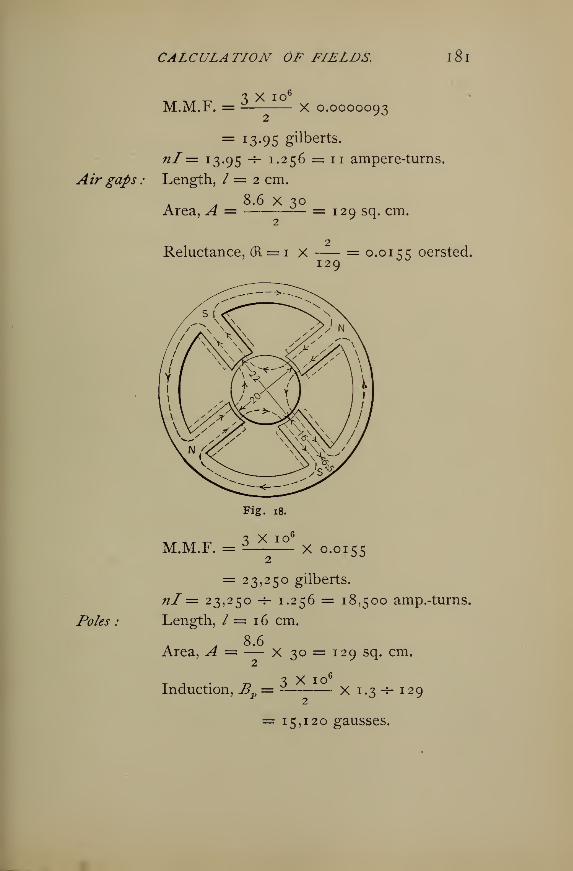
CALCULATION OF FIELDS. lSl
i y to6
M.M.F. =^ X o.0000093
= 13-95 gilberts.
nl— 13.95 -*- 1.256 = 11 ampere-turns.
Air gaps : Length, / = 2 cm.
. 8.6 x 30Area, ^4 = — = 129 sq. cm.
Reluctance, (R = 1 X = 0.0 1 c c oersted.129
Fig. 18.
/fc&r :
M.M.F. = 3 X IOx 0.0155
= 23,250 gilberts.
nl = 23,250 -r- 1.256 = 18,500 amp.-turns.
Length, / = 1 6 cm.
Area, A = — X 30 = 129 sq. cm.
Induction, B = 3 X io<X 1.3-5- 129
= 15,120 gausses.
1 82 ELECTRICAL AND MAGNETIC CALCULATIONS.
Reluctivity, k = ^2i — 0.000051 x 15,120
= 0.0016 oersted per cc.
T f\
Reluctance, (R = 0.0016 X X 2129
= 0.0004 oersted.
3 X io6
M.M.F. = X 1.3 X 0.0004
= 780 gilberts.
nl'= 780 -*- 1.256 = 621 ampere-turns.
Yoke
:
Length, /= 190 -r- 4 = 47.5 cm.
Area, A = 6.5 X 30 = 195.0 sq. cm.
t j 4.- z? 3 X io6 X 1.3Induction, B
y= -f- 195
Reluctivity, k =
10,000 gausses.
0.00045
1 — 0.000051 x 10,000
= 0.0009 oersted per cc.
Reluctance, (R == o.oooo X —^-J 9S
= 0.00022 oersted.
M.M.F. = 3 X Iq6 X Im3x 0.00022
2
= 429 gilberts.
nl= 429 -f- 1.256 = 341 ampere-turns.
As before, the coefficient of leakage is applied to the
yoke as well as to the cores, since it is uncertain just what
the leakage paths are and our error in making the leakage
factor apply to the yoke will be on the safe side.
CALCULATION OF FIELDS. 183
From our data the reluctance of a single magnetic cir-
cuit will be
(R = 0.0000093 + 0.0155 + 0.0004 + 0.00022
= 0.0 161 oersted.
Hence the combined reluctance of two parallel paths will be
0.0161 -f- 2 = 0.00806 oersted.
Also the combined M.M.F. of two parallel paths will
beM.M.F. = 13.95 + 23,250 + 780 + 429
= 2 4,473 gilberts.
nl = 24,473 -T- 1.256 = 19,485 ampere-turns.
This requires 9742 ampere-turns on each core. If we
take as exciting current 5 amperes, the number of turns
will be 9742 -r5 = 1944 on each core, requiring 5000
circular mils section, corresponding to No. 14 wire = about
80 mils diameter d.c.c.
The length of core winding =16 cm. = 6300 mils.
Hence there will be 6300 -j- 80 = 80 turns in one layer,
thus requiring 1944 -f- 80 = 24 layers deep = 24 x 0.080
= 1.9 inches. The mean length per turn = 3^ feet,
making the total length required on the fields,
/= 1944 X 3} X 4 = 24,624 feet
The resistance for the fields connected in series will be
24.63 X 2.58 = 63.6 ohms cold.
Since the resistance of copper increases about 1 per cent
for each 2 C. rise above the air, and allowing 40 rise,
the resistance will become
R hot = 63.6 + (1 % of 63.6) X — = 76.3 ohms.
1 84 ELECTRICAL AND MAGNETIC CALCULATIONS.
The voltage required for excitation is
E = 76.3 X s = 381.5 volts.
If we connect the fields so that two will be excited in
series and two in parallel, the total resistance becomes
I Q I X 2R = — =19.1 ohms hot. The total exciting cur-
rent must now be 10 amperes, and the voltage for excita-
tion becomes
E = 19. 1 x 10 = 191 volts.
The weight of wire will be 325 to 350 lbs.
Fields for alternators and direct current machines of any
number of poles are determined as in the last example.
It is impossible to be absolutely exact in these prelimi-
nary calculations, since it is not definitely known just what
the leakage paths will be and just what the behavior of
the particular quality of iron will be under test, also the
effect of joints, etc. Manufacturers, of course, must
govern their final design by tests of a finished machine as
well as by tests of the material used.
For compound wound machines, if the E.M.F. at no load
and also at full load are known, or if left for the designer
to decide, the series winding is determined so as to supply
flux through the known reluctances to make up the differ-
ence of these two E.M.F's plus the additional leakage.
Also if the armature resistance and maximum current are
given, the armature drop due to the load is Ea = IRa .
Hence if the compounding is only for armature drop, we
can determine the series winding to supply the extra pres-
sure necessary.
CALCULATION OF FIELDS. I 85
All armature bodies are laminated, so that the actual
area is reduced 10% to 20%. But since the armature
reluctance is such a very small part of the total, it will not
be necessary to correct for this reduction of area due to
lamination.
In cases where the general dimensions of a dynamo are
given, a good plan is to lay down the machine to scale on
a drawing board, then take from the drawing all distancesnl
and areas needed in calculating reluctances or— •
c
52. Original Problems. — 1. Determine the shunt wind-
ing, depth, resistance, etc., for the following machine, two-
pole, direct current. Armature body 8^" X 8", 100
grooves, two wires per groove, resistance 0.06 ohm
;
/= 30 amperes ; speed = 2025 r.p.m. ; E.M.F. no load
118 volts, full load 120 volts. Field bore %\\ inches;
core length, single, 6 inches; area 63.68 square inches;
separation at tips \\ inches ; mean length of lines of force
in each pole 17 inches;pole width 8 inches. Assume
wrought iron throughout. Also calculate the series turns
for compounding.
Shunt coil 3350 turns.
Wire No. 21 = 0.0354" covered.
Rf = 120 ohms.
Series coil 17 turns of No. 3 = 0.283".
Resistance series 0.013 ohm.
2. What will be the required number of series and
shunt turns for the following two-pole, direct current ma-
chine ? Armature body 8" X 6"; 64 coils, 3 turns each
;
resistance 0.85 ohm ; speed 2400 r.p.m. ; E.M.F. no
1 86 ELECTRICAL AND MAGNETIC CALCULATIONS.
load no volts; full load 116 volts. Field cores each
6 inches long, 5^ inches diameter; pole heads from top
of cores to center line of armature 15 inches; area of
pole heads 8 X 3= 24 square inches ; tips 2% inches
apart. Yoke length for lines 13 inches ; width 8 inches;
depth \\ inches. Air gap including the wire on the
armature 0.3 inch. The yoke is of cast iron ; armature
Norway ; cores and poles dynamo wrought iron. Leak-
age factor is 1.25.
Shunt 4850 turns No. 20 wire.
Series 46 turns No. 8 wire.
3. A small 50-volt, 8-pole alternator has an armature
core 5^ inches diameter and 6 inches long, and is wound
with 8 coils, 6 turns each, No. 14 wire. The external
diameter of the field ring is 13.5 inches, internal n inches;
width 5 inches. The clearance is 0.3 centimeter. The
poles are 1" X 6", and 2\ inches long. Speed of armature
2000 r.p.m. All parts are made of wrought iron. Allow-
ing about 600 circular mils per ampere in fields, find the
number of turns and depth of wire on each core.
Field 492 turns, 12 layers of No. 19.
Total, 8 cores = 3936 turns.
Depth on each core 0.6 inch.
Rf = 42 ohms if connected in series.
4. A consequent pole machine similar to the one pre-
viously worked out has the following data taken from it
:
Armature body 8" X 8"; slotted for 200 wires, 2 per
groove; speed 2400; E.M.F. 116 volts; core laminated
Norway iron ; field cores wrought iron, 6 inches long, 4
CALCULATION OF FIELDS. 1 8/
inches diameter;yokes cast iron, 3 inches wide, 12 inches
between core centers;poles cast iron, 8 inches between
cores, 5 inches perpendicularly, tips separated 4 inches.
Air gaps are 0.15 cm. each. Determine the turns neces-
sary to wind the machine as a shunt motor, allowing 2
amperes for exciting current. Also calculate the length
of wire, its depth, resistance and weight.
11 = 810 turns each core; 3240 total.
Length of wire 3825 feet of No. 20.
R/= 43 ohms, allowing 20% for rheostat.
Depth with insulation 0.4".
Weight 12 lbs.
5. The drum armature for a 25-K.W. machine, 125
volts, is 1 1.5 inches long, 11.5 inches diameter. Ba =10,000 gausses; speed 1000 r.p.m. There are 112 arma-
ture conductors. Fields are Edison type, wrought iron.
Core length, exclusive of collars, etc., 16.6 inches ; diame-
ter 1 if inches. Height from top of yoke to lower end of
poles 42 inches. Total length of yoke 34 inches. Air
gaps, including winding, insulation, etc., on the armature,
0.05 inch. Pole tips 3 inches apart. Draw a diagram
and determine the length of flux paths. Also determine
the field winding for an exciting current equal to 2.5 per
cent of output and for a leakage factor for this type
of 1.6. n = 1750 turns, each core.
Wire No. 13 ; length 11,060 feet.
Rf — 22.18 ohms.
Note.— A smaller size of wire may have been used,
say No. 14 wire, without undue heating. The No. 13
wire was obtained by taking the resistance which the
winding at 125 volts must have to allow just the required
1 88 ELECTRICAL AND MAGNETIC CALCULATIONS,
exciting current to flow, and assuming at the outset a
depth of winding about J of core*radius in order to obtain
the length. Whence d2 = -—— = 5000 circular mils,
approximately. This may be used as a satisfactory check
on any method of determining the field winding, or as
the primary method, itself, to be checked by others.
6. The following data for an Edison-Hopkinson ma-
chine are taken from Thompson's " Dynamo-Electric Ma-
chinery":* normal output 320 amperes at 105 volts;
speed of armature 750 r.p.m., diameter of armature
core 25.4 cm., length 50.8 cm., carrying 40 turns, 2 lay-
ers deep; wire 1.75 mm. diameter. Magnet cores nearly
rectangular, rounded corners ; all material wrought iron
;
length of magnet limb 45.7 cm.; breadth 22.1 cm.;
width parallel to shaft 44.45 cm * Length of yoke 61.6
cm. ; width 48.3 cm. ; depth 23.2 cm. Diameter pole
bore 27.5 cm.; depth of pole piece 25.4 cm.; width
parallel to shaft 48.3 cm. ; width between pole pieces
12.7 cm. The area of iron in the armature is 810 sq. cm.
The angle subtended by the pole face is 129 . Effective
area of pole is 1600 sq. cm. The air gap is 1.5 cm. De-
sign the shunt winding for 6 amperes exciting current.
n = 3260 turns, 11 layers on
each core, No. 1 2 wire.
J?/= 17 ohms, approximately.
7. An 8-pole direct current machine has an armature
3 1.1 cm. X 13 cm. cross section, Gramme ring type, 0.92
of area effective, on account of insulation of the ribbon of
* Dynamo'Electric Machinery,page 413.
CALCULATION OF FIELDS. 1 89
armature. Speed is 1722 r.p.m. The armature carries
768 conductors. Ba = 9,500 gausses. External diame-
ter of armature ring is 147.3 cm - 5 finished, 149.3 cm.
Internal diameter of ring, 12 1.3 cm.; finished, 119 cm.
The external diameter of pole ring is 231 cm.; internal
diameter, 218.4 cm « ; width parallel to shaft, 34.3 cm.;
width of cores, 29.5 cm. The poles widen at the air gap
so the latter is 41 X 34= 1400 sq. cm. The armature
coils are parallel connected. Determine the E.M.F., the
reluctance and field winding, the armature being soft iron,
the fields all cast steel. If the exciting current be 10 am-
peres, how many turns and how deep on each core ?
E= 155.7 volts.
nl = 7333 each spool.
n = 734 turns each.
Depth = 1.4".
(ft/ = 5.214 X 1 o~3 oersted.
8. An iron-clad armature for a multipolar dynamo has
been designed so that it requires in its teeth from each
air gap 20.4 x io6 maxwells of flux. The armature is of
sheet iron 14 inches long, cross section of teeth under
pole 151. 5 sq. in. ; length of teeth 1.75 inches; armature
cross section 124.3 scl-m - Ah" gap, length 0.25 inch;
area 538 sq. in. Field poles, cross section 237.2 sq. in.
;
length 16 inches, cast steel. Yoke, section 132 sq. in.;
length 28.5 inches, cast steel. One coil on each pole
will require how many ampere-turns each, leakage coeffi-
cient being assumed as small as 1.2 ?
nl= 5850 ampere-turns.
19O ELECTRICAL AND MAGNETIC CALCULATIONS.
XL
ELEMENTS OF DYNAMO DESIGN.
53. General Considerations.— There is such a diversity
of elements upon which the judgment must depend in
the proper design of machines of the same type, to say
nothing of different types, that only those details which
illustrate the general principles of dynamo design can be
given in this chapter. The general theory of the dynamomust be understood and the exact character of all the
material going into its construction. Observation and
test of various types and sizes of practical machines must
be made use of. Then the manufacturers must gather
experience, not only from continuous tests of all material
used, but from the performance and tests of the completed
product. In fact, there are so many interdependent
quantities which themselves depend on the conditions of
service and exact quality of material, that an approxima-
tion to exactness is all that can be expected in a pre-
liminary design.
54. Useful Data. — (1) The output of dynamos is ap-
proximately proportional to their weight, or to the cube
of a linear dimension, if of the same type, since the larger
must have reduced speed, increased efficiency, greater
radiating surface, etc. Double the weight of copper and
double the weight of iron should give double the output.
The output will be about 6 watts per pound for continu-
ELEMENTS OF DYNAMO DESIGN 191
ous current belted dynamos, and 8 watts per pound for
direct driven multipolar machines.
(2) The temperature of armatures should generally not
exceed about 50 C. above the air. Although the subject
is somewhat indefinite, yet tests tend to show that the
amount of external surface in an armature should be taken
so that 1 sq. in. may be allowed for each 2 to 2} watts
lost in the armature. Of this loss about 1 watt per sq. in.
will be due to PR loss, and the rest to hysteresis and
eddy currents.
For example, if the I2R loss is 2% of 100 K.W. =2000 watts, the external surface of the armature should be
= 2000 sq. in. In designing armatures this method
may be used for determining the size of armature. In
any event it should be used as a check on any other
method employed to obtain the required size of armature.
If armatures are internally ventilated, a smaller area per
watt can be used.
The fields should have somewhat larger surface per
watt lost owing to the fact that the winding is deeper and
there is no mechanical ventilation as in armatures. Some
recommend 2 square inches per watt lost in field wind-
ings. This may be assumed as a safe limit, though in
many cases only 1 square inch per watt is allowed.
In very small sizes of machines the temperature is per-
mitted to go higher, since the same efficiency is not
attempted as in large sizes. Often as low as 250 to 400
circular mils per ampere is used for the armature wires
and 500 to 800 for the field windings. But as a working
average for ordinary machines 600 circular mils per
192 ELECTRICAL AND MAGNETIC CALCULATIONS.
ampere should be taken for armature conductors, and
800 to 1000 circular mils per ampere for the fields.
(3) The proper I2 R losses for armatures and fields
may be arrived at from the following table derived from
several standard modern machines of various sizes.
7. Table of I 2 J? Armature and Field Losses.
Size.ArmatureLoss %.
Field Loss %.
100 K.W.50 K.W\25 K.W.5 K.W.
2.0
2,2
2-5
4.0
I.I
1.6
2.5
4-5
(4) Peripheral speeds of armatures vary from about 3000
feet per minute as an average in ordinary sizes, to 5000
feet per minute or more in very large sizes such as
Ferranti disk armatures.
( 5 ) The angle of span of the poles in two pole dynamos
varies from 120 to 145°. An educated judgment as to the
proper separation of the pole tips so as to reduce leakage
can be relied on in this particular. Poles may cover
about three-fourths of armature surface. Say 0.6 to 0.75.
(6) The armature laminae vary in thickness from 25 to
50 mils ; say 30 mils as an average. Usually 10 per cent
to 20 per cent may be allowed as a reduction in the arma-
ture cross section for insulation between laminae and
shaft space.
( 7 ) For armature proportions we may take the ratio of
the external to the internal diameter 10 to 8 ; sometimes
10 to 7 is used. For drum disks the ratio is about 10 to
3. These values are not rigid. Different values would
ELEMENTS OF DYNAMO DESIGN. 1 93
perhaps be assigned by different designers. The ratios
of drum armature lengths to diameters vary considerably.
But representing the length by / and the diameter by d,IIthe ratios are most often— = 1, — = 2, or some ratio be-
d a
tween these. For ring armatures the ratios vary from
/ /
-d=*t0
-d= 2 -
( 8 ) Flux densities in armatures for constant potential
direct current machines vary between 10,000 gausses and
15,000 gausses. However, it is not often advisable to go
beyond 12,000 gausses. For arc machines the density
often reaches 18,000 gausses. Perhaps 16,000 gausses
will represent the average flux density for such machines.
For alternators the density is considerably less, varying
from 6000 to 7000 gausses, while in coreless disks it is
about 5000 gausses.
Air gap intensities vary from 3000 to 7000 gausses in
direct current machines, and from 2500 to 5000 in alter-
nators.
Field densities vary from 12,000 to 17,000 in both direct
constant potential machines and alternators. It will be
about 18,000 gausses in arc machines. These values are
all for wrought iron. When cast iron fields are used
6000 to 8000 gausses is as high as permissible in any
type.
(g) For relative cross section of field and armature
Thompson gives the following ratios of field to armature
;
ring machines, wrought field, 1.66; cast field, 3. For
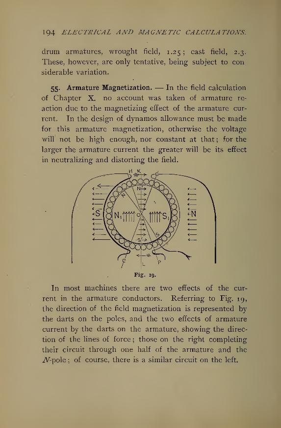
194 ELECTRICAL AND MAGNETIC CALCULATIONS.
drum armatures, wrought field, 1.25; cast field, 2.3.
These, however, are only tentative, being subject to con
siderable variation.
55. Armature Magnetization. — In the field calculation
of Chapter X. no account was taken of armature re-
action due to the magnetizing effect of the armature cur-
rent. In the design of dynamos allowance must be made
for this armature magnetization, otherwise the voltage
will not be high enough, nor constant at that ; for the
larger the armature current the greater will be its effect
in neutralizing and distorting the field.
H K
Fig. 19.
In most machines there are two effects of the cur-
rent in the armature conductors. Referring to Fig. 19,
the direction of the field magnetization is represented by
the darts on the poles, and the two effects of armature
current by the darts on the armature, showing the direc-
tion of the lines of force ; those on the right completing
their circuit through one half of the armature and the
iV-pole ; of course, there is a similar circuit on the left.
ELEMENTS OF DYNAMO DESIGN. 1 95
The brushes stand in the plane, CC called the commutating
plane ; HOC is double the angle of lead, which is KOC
;
LK is the normal plane, and if there were no skewing
effect due to armature reaction, it would be the plane
containing the brushes. The turns in the angle HOC,four in this case, set up an armature magnetization
directly opposed to that of the field. These turns are
therefore called back ttirns. The rest of the armature
turns, approximately those coming under the span of the
poles, set up a magnetization whose lines tend to cross
those due to the field, and whose poles in the armature
tend to be at right angles to those induced in the arma-
ture by the field. These armature turns are called cross
turns. Since there cannot exist two independent sets of
poles in the armature core, there will be a resultant of
the induced magnetization NXSX and the cross magnetism
IPS', along the line JVS diagonally between the com-
ponents. The combined effect is apparently a pulling
down of the lines in one pole and a pulling up in the
other in the direction . of revolution ; and the resultant
magnetism passes diagonally up through the armature
core instead of horizontally as it would were there no
armature magnetism.
The ampere-turns on the armature causing the back
magnetization are
Back ampere-turns = nh X \I (IO°)
in which nb is the number of conductors within the double
angle of lead. In the figure nb = 4. Also / is the
whole current output of the machine.
196 ELECTRICAL AND MAGNETIC CALCULATIONS.
The ampere-turns on the armature causing the cross
magnetization are
Cross ampere-turns == nc X \ /, (IQI )
in which nc is the number of conductors on one-half the
armature less nb , the number in the double angle of lead.
In other words nc is the number counted within the
angle COP or COH. I, as before, is the total armature
current. We take \ I, since each conductor carries but
one-half the total current.
Suppose, as in the figure, that there are 14 cross turns
and 20 amperes output. The back ampere-turns are
4 X \ X 20 = 40, and the cross ampere-turns are
14 X \ X 20 = 140.
If no other means of knowing what portion of the sur-
face turns are back and what cross, an approximation may
be made by taking, the number between the pole tips as
the back turns and those within the span of the pole as
cross turns.
Evidently when the angle of lead is known the number
of turns within double this angle is readily found. For
example, let a be the angle of lead and n the whole num-
ber of armature turns ; then
2 a a
180 90
Let a= 1
5
.
Then nh= -2— = -
90 6
56. Compounding. — The shunt field winding is the
only one effective when the machine is on open circuit
;
that is, when it is running at normal speed, but unloaded.
ELEMENTS OF DYNAMO DESIGN K)J
Therefore the regulation must be effected by compound-
ing the dynamo ; that is to say, by adding coils on the
cores in series with the circuit and with the armature.
These series coils must compensate for the drop in the
armature resistance and in their own resistance ; they
must also compensate for the effects of the back and the
cross magnetizations ; they must in addition compensate
for the effect of the increased saturation of the fields and
armature when the machine is loaded. Furthermore in
the case of over compounding, still more series turns must
be added to compensate for a certain amount of line
loss.
57. Useful Formula. — Volts drop : let Ra = the
armature resistance, / the armature current, Ea = the
volts drop in the armature. Then
Ea = RJ. (102)
If Rsis the field resistance, I
s= the field current,' Es
=the field drop, then
Es= RJS
. (103)
Since the shunt winding and the external circuit are in
parallel, Esis the same as the external, or line E.M.F.
The current in the field winding is the total current times
the shunt field loss per cent. This varies somewhat with
the size of the machine; see Sec. 54* But in ordinary
sizes it will be about 2.5%.
The series field drop will be
Ef=RfIe . (104)
Rf is the resistance of the series winding, Ie is the current
198 ELECTRICAL AND MAGNETIC CALCULATIONS.
carried to the external circuit ; it is the total / less the
shunt field exciting current Is . In other words,
/=/« + /.. (105)
It will make but little difference in the temperature of the
armature to design its coils for the external current, mak-
ing it carry in operation the extra amperes necessary for
the shunt excitation.
The E.M.F. to be generated in the armature coils is
E = Ea + Ef+Ee. (106)
Strictly speaking, Ea includes the drop due to cross and
back turns as well as the IR drop in the armature con-
ductors.
The e?iergy lost in the armature is
Wa=£a x7=(£ -Ee- £/) I. (107)
Eeis the terminal or line E.M.F.
The watts lost in the shuntfield are found by
Ws= EJS
= EJS= RJS\ (108)
The seriesfield loss is given by
Wf=Ef It = RfI?. (109)
The eddy current* loss in the armature, from Stein-
metz's formula, is
We = V(tfbf X IP" 16. (no)
See Sec. 42 for (no). Several conditions may render
the results of the actual tests on the dynamo widely
diverse from these given in (no). Yet the latter will
serve very well as a check.
* See Equation (58).
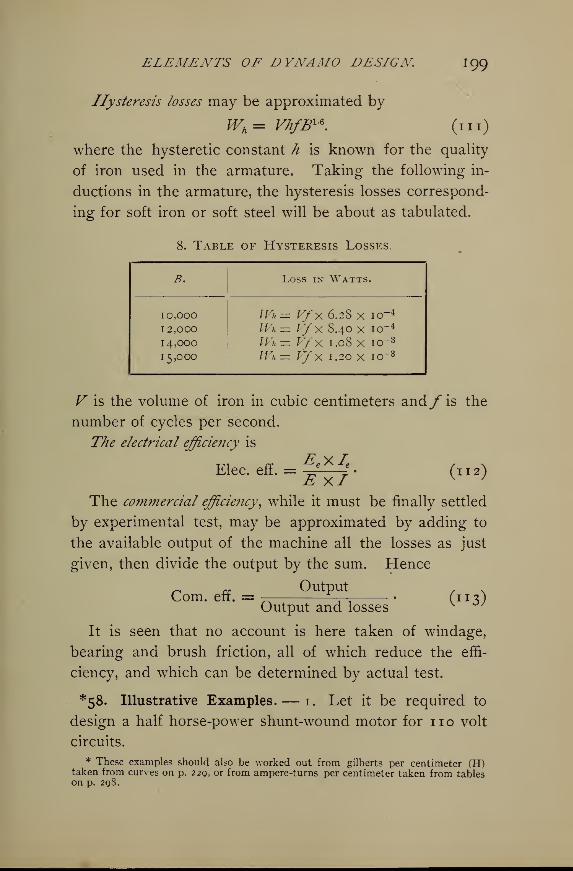
ELEMENTS OF DYNAMO DESIGN I 99
Hysteresis losses may be approximated by
Wh = Vhf&\ (in)
where the hysteretic constant h is known for the quality
of iron used in the armature. Taking the following in-
ductions in the armature, the hysteresis losses correspond-
ing for soft iron or soft steel will be about as tabulated.
8. Table of Hysteresis Losses.
B. Loss in Watts.
IO.OOO
12,000
14,000
15,000
Wk= Vfx 6.28 x io-4
Wn— Vfx 8.40 x io~4
Wh = Vfx 1.08 x io-3
JVh — VfX 1.20 X I0~3
V is the volume of iron in cubic centimeters andf is the
number of cycles per second.
The electrical efficiency is
Elec. eff. = 5^4*- (112)
The commercial efficiency, while it must be finally settled
by experimental test, may be approximated by adding to
the available output of the machine all the losses as just
given, then divide the output by the sum. Hence
OutputCom. eff. = (»3>Output and losses
It is seen that no account is here taken of windage,
bearing and brush friction, all of which reduce the effi-
ciency, and which can be determined by actual test.
*58. Illustrative Examples. — 1. Let it be required to
design a half horse-power shunt-wound motor for no volt
circuits.
* These examples should also be worked out from gilberts per centimeter (H)taken from curves on p. 229, or from ampere-turns per centimeter taken from tableson p. 298.
200 ELECTRICAL AND MAGNETIC CALCULATIONS.
As small a machine as this, especially if it runs light
part of the time, cannot be expected to supply its power at
greater than 60% to 70% efficiency. Hence the intake
will be, say v- 0.60 = 625 watts. At no volts there
will be 5.6 amperes of current. Allow 400 circular mils
per ampere, requiring — x 400 =1120 circular mils.
This is nearest No. 19. We may approximate 10% PRlosses in fields and in the armature, making each 62.5
watts lost. Suppose we use the allowable temperature
rise as a basis for solving the armature in this case. If we
allow 1 watt loss per square inch of external surface, we
obtain the size as follows : let d = the core diameter,
/ = its length. Consider that these shall be equal. The
end surfaces are 2 d2 X 0.7854. The convex surface is
d X 7T X /. Since d = /,
2 /2 X 0.7854 + ?r/2 = 62.5,
62.
c
and P =—— • Whence / = 4 inches.4.7
For the fields the current will be
10% of 5.6 = 0.56 ampere.
This at 800 circular mils per ampere requires 448 cir-
cular mils, or No. 24 wire, having 26 ohms per 1000 feet
cold. Assuming a rise in temperature of 40 C above the
air, and taking 1 % increase for each 2-J-° rise, the resis-
tance, hot, will become about 116% of 26 = 30 ohms per
1000 feet. The field coils must have a resistance of
no -f- 0.56 = 196 ohms. Therefore the length = 196
+ 3° = 6533 feet -
ELEMENTS OF DYNAMO DESIGN 201
d>nvFrom (79) E = -^—g- • Since E = no, taking v = 30
r.p.s., assuming ^ = 6000 gausses, and 70% available
armature cross-section, we have
no x io 8
n = t rs 7 = 9°° wires -
(4 x 2.S4)2 X 0.70 X 3° X 6000
Take, say 20 commutator segments, thus requiring 900 -r-
20 = 45 wires per coil and per slot, and 22 turns per
coil. Divide the circumference of the armature into 40
parts, half of it being for slots. Circumference = 4?r =12.56 inches. Hence each slot will be 12.56 -r- 40 = 0.3
inch wide. No. 19 wire is 35.4 mils bare, or about 50
mils d.c.c. This will allow 0.31 -*- 0.05 = 6 wires in one
layer in each slot ; and the slots must then be 44 h- 6 = 8
layers deep. The wire space in depth = 0.05 X 8 = 0.4
inch. The slots must be insulated on the sides and
bottom, say to the thickness of one wire. Hence 5 wires
wide will require 9 wires deep + space for insulation = 10
wires deep. Depth therefore = 0.05 X 10 = 0.5 inch.
This will perhaps be also sufficient to allow for bond-wire
space.
The total length of wire on the armature will be about
750 feet, allowing for piling up on the ends and for com-
mutator connections. No. 19 has 8.5 ohms per 1000 feet.
Hence the I2E loss will be 5.6sX 1.6 13 = 50 watts, or a
little less than 10% as assumed at the outset. We get
1.6 1 3 as the hot resistance of 750 feet -7- by 4 for the
maximum armature resistance.
We may take the laminae for the core 0.04 inch thick.
The volume of the core = 10 x 0.7854 x 10 = 785.4 cc.
202 ELECTRICAL AND MAGNETIC CALCULATIONS.
Applying table 8 under (in), taking the constant at 5
and calculating the hysteresis loss, we have
Wh = Vfx 5 x io- 4 = 785.4 X 30x5 X 10- 4
= 12 watts.
Also for eddy currents from (no)
We = V(tfl?)2 X 10- 16 = 785.4(40 X 30 X 6000)2 X io~ 16
= 4 watts.
The total armature loss is 50+12 + 4 = 66.
But since only half the external surface is iron the flux
density will be doubled in the teeth, so that both hysteresis
and eddy currents will be greater in the teeth. If neces-
sary the volume of the teeth may readily be determined,
also the volume of the rest of the core, with their corre-
sponding flux densities, and the iron losses for these parts
determined separately. This would perhaps increase the
above value to 70 watts, or more.
Calculation of Field. — Assume the coefficient of leak-
age to be v = 1.5, thus making the lines of force in the
cores of the field magnets become
<f>f = 70 x 6000 x 1.5 = 630,000 maxwells.
We shall make the core of wrought iron, but for purposes
of rigidity it will be better to make it larger than other-
wise necessary. Hence take B = 8000 gausses. Whence
D of cores =4/6^000 _ = IO cm . = 4 in .
8000
Now if the poles and core are all of wrought iron 4 inches
will be ample ; but if cast iron be used the area of cross
section must be somewhat larger so as to reduce Bf to
ELEMENTS OF DYNAMO DESIGN 203
6000 gausses, perhaps. Use single yoke core. Allow a
clearance of 0.08 inch, or 0.16 inch both sides.
Now to approximate the length of the magnetic circuit:
from middle of pole face through pole to a point on a
level with under side of the armature, say 3 inches;
thence to top of field-winding, say 1 inch ; thence to
center of core, that is, wire and half of core depth, say 4
inches;yoke, say 4 inches, core length, making total
approximate field circuit 20 inches. Also make poles of
such shape and dimensions as that their cross-section will
be approximately equal to that of the armature = 4 X4=16 sq. inches =100 sq. cms.
Now for the field core the reluctivity is
a 0.0004
1 — bB 1 —0.000057 x 8000
= 0.00073 oersted per cc.
_ _ / 10.16 .
0tc = k - = 0.0007 3 x — = 0.000004 oersted.a ,0
78.54**
The rest of the field will be 16 inches = 40.64 cms. long
and 16 sq. inches = 103.25 sq. cms. section.
tx r> 630,000Hence J3f = = 6000 gausses.
103.25
And k = 0.0006 oersted per cc.
r 40.64(R.f = 0.0006 x = 0.00023 oersted.
io3- 2 S
For the air gap, assuming all the lines to pass through it,
the reluctance will be
0.4(JL = = 0.004 oersted.y 100
204 ELECTRICAL AND MAGNETIC CALCULATIONS.
Hence, neglecting the reluctance of the armature, the
total reluctance will be
61, = 6LP + 61^ + 6lc = 0.004324 oersted.
The approximate ampere-turns are
<£6l 630,000 X .004324nl =— = - = 2170.
0.47T 1-256
Therefore the number of turns will be
2 1 70n = —— = 3875 turns of No. 24 wire.
This will have a diameter of 35 mils d.c.c. The length
of wire already found is 6533 feet. Allow 20 per cent of
this for the regulating rheostat, leaving
80% of 6533 = 5226.4 feet for field wire.
The mean length of one turn will be 5226.4-7-3875 =1.35 ft. mean circumference of winding. The mean
j -2 r V j2diameter will be -^ = 5.2 inches, making the
3- J 4
depth of wire 5.2 — 4 = 1.2 inches. Allow 0.1 inch for
core insulation, and we have for wire space, 1.2 — 0.1 =1.1 inches, requiring 1.1-7-0.035=31 layers deep. There-
fore the cores must be long enough ^3875-7-31 = 125
turns in one layer. The length for wire space is then
125 X 0.035 = 4-38 inches.
Allow I inch for fiber collars at each end of core ; this
makes the total wire space 3.75 inches, shortage being
made up in greater depth, if the four-inch core be used.
ELEMENTS OF DYNAMO DESIGN. 20$
To correct our data. The core reluctance will not be
appreciably changed, since the corrected core length is
only a little different from that assumed. The diameter
of pole bore is 4 + 0.16 = 4.16 inches, circumference
= 13.06 inches. Choose the angle of span = 120 , thus
, . , - r 1 r I2 ° 13.06making the length of curve of pole face = -r— X —— =00 180 2
4.3 inches. The separation of pole tips will then be
13.06 — 8.6 . , _, ,-^ = 2.23 inches. Pole face area = 4.3 X 4 =
2
17.2 sq. inches. We may so shape the poles that the
average area will be about 16 sq. inches as assumed, and
so no correction for field area need be taken.
Now to obtain exact length of flux lines. From the
center of pole face horizontally 2 inches ; vertically down
3 inches to top of winding ; 1.6 inch depth of winding;
2 inches to core center. The total = 6.6 inches to a
horizontal line through the center of core. Thence say
2.5 inches inward to core end, making 11.1 inches on one
side exclusive of core. But the curving of the flux paths
in the field parts will reduce this to say 10 inches, or
20 inches on both sides. Our assumed length was
16 inches. Hence the reluctance of this portion will be
I of the assumed value. Therefore f of 0.00023 =0.00029 oersted. The total reluctance will now be
0.004388, and the ampere-turns 2200 instead of 2170.
Hence an additional layer of wire on the core will be
sufficient, especially since our calculations assume that
the total core flux passes through the complete field
circuit.
Now a little time on the drawing-board* will suffice to
206 ELECTRICAL AND MAGNETIC CALCULATIONS.
represent the machine to scale, with the proper forming
of the outline so as to present a satisfactory appearance
and to save any iron possible whose removal will not
prejudice the operation of the machine. Show substan-
tial arms cast on the poles to support the armature bear-
ings, and design feet to bolt on slide base.
Summary:— Armature 4" X 4"5 speed 1800 r.p.m.
Current 5.6 amps. ; Ra = 1.61 ohms.
Wire length 750 feet ; size No. 19 d.c.c.
Coils 20 having 22 turns each.
Laminae 100, 0.04 inch thick.
Shaft |".
Fields, core 4" long, 4" diameter.
Area 13 sq. in.; wire space 3.75" in.
Flux length 10 inches each limb.
Total flux path 24".
Current 0.56 ampere ; turns 3875.
Wire length 5300 feet, No. 24 wire.
Span of poles 120 ; separation 2.3'
Losses, armature/2^ =50 watts.
" Iron = 20 "
" Total = 70 "
Field 72i?= 62 "
Total =132 "
jr
Efficiency =^ +^ + 132)= 74%.
2. Required to design a 5 K.W. bi-polar direct current
machine for 120 volts full load.
As a check suppose we determine the size of the
armature in two ways. First taking the peripheral speed
at say 3600 feet per minute ; also 1800 revolutions per
ELEMENTS OF DYNAMO DESIGN. 20J
minute as a good speed for this size of machine. The3600 2
diameter of the armature must be -^ = - ft. = 8 inches.__ , . . . - n . . IO007T 7T
Take also a length or 8 inches.
Second, if we take i-J- sq. inches per watt of I2R loss
which according to the table will be 4% for a 5 K.W.
dynamo, the diameter of the armature will come out as
follows: d2 X 7T + 2d2 X 0.7854 = 1.5 X 200.
d = 8 inches, nearly.
We shall therefore work on the basis of an armature
8" X 8", running at 1800 r.p.m. = 3780 feet per minute,
peripheral velocity.
The armature current is
coooIa = = 41.7, say 42 amperes.
120
At 600 circular mils per ampere, the wire must be —X 600 = 12,600 cir. mils, which is between Nos. 10 and 9.
Take No. 10 = 10,381 cir. mils. = 500 circular mils per
ampere.
If we choose 4 volts between adjacent commutator bars
there will be
2 x ( ) = 60 commutator bars,I2o\
~4/This might be made 50. Also
j£Xio 8 E X io 8
n = = •
<t>v BAvDeducting 20% from armature cross section,
A = 64 X 0.80 = 51.2 sq. in. = 330.24 sq. cms.
Hence ati?a = 10,000 gausses, <£a = 3,302,400 maxwells,
So that Q120 X io8
// = =120 conductors = 60 coils.3,302,400 x 30
208 ELECTRICAL AND MAGNETIC CALCULATIONS.
If we choose 60 commutator bars there will be 1 turn in
each coil. If we make 60 slots on the armature the wires
will be 2 deep in each. Let the slots occupy half theO y*
surface; then each will be = 200 mils wide. Now120 *
No. 10 wire = 10 1.4 mils uncovered, or about 120 mils
d.c.c. The sides and bottom of the slots must be fibered,
say 44.5 mils each to make up to about 209 mils; i.e.,
120 + 2 X 44.5 = 209. Two wires deep make 240 mils,
which added to, say, 50 mils insulation in the bottom,
make 290 mils. Further, the bond-wires, say No. 18 =40 mils, and the insulation under them, say 20 mils, make
an additional depth of 60 mils, thus requiring the slots to
be 350 mils deep.
Now if we may assume that the flux lines enter the
teeth only, their density in the teeth will thus become
20,000 gausses, since only half the surface is iron.
The I2Ra loss may now be estimated as follows : mean
turn = (8 — 0.35) X 2 + (8 X 2) = 31.3 inches. Allow
25 per cent for rounding the shaft and piling up and
making commutator connections, making the total length
of wire on the armature equal
31.3 X 1.2c; x 60 , r2—
2
5 a 195.625 feet.
No. 10 has a resistance of 1.023 ohms per 1000 feet.
Hence our armature wire will have a resistance of
0.1956 X 1.023 = °- 2 ohm » The resistance of the arma-
ture is therefore \ of 0.2 = 0.05 ohm cold. To allow
40 C. rise will increase this about 16%, making 0.06
ohm hot. Hence
PRa = (42 + 4.5% of 42)2 X 0,06 = 116 watts.
ELEMENTS OF DYNAMO DESIGN 209
We allow the armature current to increase 4.5 per cent to
supply the field current. The per cent loss will now be
116 -*- 5000 = 2.5%, or somewhat less than the tabular
value for machines of similar size.
To calculate the fields. Take two cores, wrought iron;
use cast iron poles, and the cast iron bed-plate for yoke.
The leakage coefficient we shall assume to be v = 1.4 to
be on the safe side. <f>/= 3,302,000 X 1.4 = 4,623,000
maxwells. AllowingBc= 15,000 gausses, the core diameter
will be
_, . /4,62^,000-H K,000 n . ,Dc= I/ -—- = 19.8 cms. = 7.7 inches.
V 0.7854
Consider 4,000,000 lines to pass through the poles and
Bp= 8000 ; then the area of poles will be
Ap = 500 sq. cms.
Since the length of the pole bore = 8 inches = 20.32 cms.,
the curve of pole face must be 500 -^ 20.32 = 24.5 cms.
Make the clearance -| inch, thus requiring the circum-
ference of polar bore to be 8.25 X -k = 25.9 inches =65.78 cms. Therefore the separation of pole tips =65.78 — 24.5 X 2 .
-^-j. ^ = 8.39 cms. = 2>-?> inches. The angle
of span is ,9 X 180 = 134 . We shall let this stand
65.78
as satisfactory. However, it would be possible to in-
crease polar density somewhat, thus reducing the angle
of span, which in turn would tend to reduce leakage.
There will, of course, be ample cross section in the bed-
plate; hence Bywill perhaps not exceed 5000 gausses, or
2IO ELECTRICAL AND MAGNETIC CALCULATIONS.
6000 at the most. At 2 amperes exciting current the
field loss is
I^Rf = 120 x 2 = 240 watts.
There will be 120 watts dissipated in each coil which, if
we use the rule of 2 square inches per watt, will have
240 square inches external radiating surface.
As a first approximate solution take § inch as depth
of wire on field core. The length of the core will
be 240 -r- [(7.7 + 2 X I) X 7r] = 8 inches = 20.32 cms.
The average length of the pole will be about 5 inches =12.7 cms. The finished coils should stand about 4 inches
apart; therefore the yoke length will be about 13 inches
= 33 cms -
For cores,
_ 0.0004 /-
k = = 0.00276;
1 — 0.000057 X 15,000
20 3 2 X 2(Rc = 0.00276 X —-—5 = 0.000364.
308
For poles,
. 0.0026 .
k = = 0.0102 oersted per cc;1 — 0.000093 x 8000
1 2 1 X 2(R„ == 0.0102 x — = 0.000C2 oersted.
500*
For yoke,
0.0026^r,r,rZ%.k = = 0.00C00
;
1 — 0.000093 x 6000
6iy= 0.00588 x 7^— = 0.00032 oersted.
Next to find the armature reluctance, first find that of
the teeth at B = 20,000, then of the rest of the armature
ELEMENTS OF DYNAMO DESIGN 211
body at B = 10,000. The number of teeth under the
pole = \\% x 30 = 22 teeth whose area = 22 x 0.209 x
2.54 X (8 X 2.54) X 0.80 = 190 sq. cms. Take ^ = 30
from table 13 at B = 20,000; £ = -=0.033. ®-t—°'°33
°'88 9 X 2 oat rX = 0.000308. Area of rest of armature =190
(20.32 — 1.778) X 20.32 X 0.80 = 301.38 sq. cm. Length
of lines through this, say 20 cms., allowing for curving
round the shaft.
Ba = 3,302,400-7-301.38 = 10,000, approximately.
_ 0.0004ka = = 0.00093 ;
1 — 0.000057 x 10
(ft = 0.00003 x = 0.00006 oersted.301
Diam. of polar bore = 65.78 -r- 3.14 = 20.95 cms.
Length of air gap = 20.95 ~~ 2 °-3 2 = 0-63 cm.
. . soo + 190Area air gap = — =345 square cms.
Hence <JL = ——- = 0.00182 oersted.345
Armature,
3,302,400 (0.000308 -f- 0.00006)
I.256
= 968 ;na = 48 4.
Cores,
4,623,000 X 0.000364(«/)c =
Poles
1.256
= 1340 ; nc = 670.
, „ 4,000,000 X O.OOOC2 ^ ^ n n( )p
= ^^6 = l6s6
;
"*= 828 '
212 ELECTRICAL AND MAGNETIC CALCULATIONS.
Yoke,
. _N 4,000,000 X 0.00032(«/% = —g =1018; ^=509.
Air,
/ r\ 3,302,400X0.00182(^). = — ^ = 47^5 ;
n = 2393.
Total ampere-turns = 9767 ; ?^ = 4883 turns. /2^?/ =
240 watts; Rf = —g" = 6° ohms. The core diameter =
7.7 inches ; assuming depth of wire \ inch, mean length
tt(7.7 + 0.87c)of one turn = w ' ^ = 2.24 feet.
12
The total length of wire = 2.24 x 4883 = 10,938 feet.
Hence Rf per 1000 feet = 60 -r- 10.938 = 5.5 ohms, cor-
responding approximately to No. 17 = 2048 circular mils,
making 1024 circular mils per ampere of exciting current.
No. 17 wire = 45.3 mils bare =55 mils d.c.c. Allowing \inch for collars on the core, there will be in one layero _ n r
^. = 136. Hence 2442 turns on each core require 18
layers deep = 0.99 inch. This exceeds \ inch given for
the depth of wire ; but the core need not be lengthened,
since only 18 layers deep are required, (0.99-^0.055). In
one layer there will then be 2442 -*- 18 = 136 turns =136 X 0.055 = 7-5 inches for winding space. Adding
\ inch at each end for a collar, we have 8 inches for total
core length. Now this will not change the core reluctance
nor ampere-turns from their assumed values of 0.000364
and 670 respectively. The total turns are 4896, or 2448 on
each core. This again will make a slight difference in the
resistance, which will now be 4896 X 2.24= 10.97 thousand
feet having 5.18 X 10.97 =56.8 ohms; assuming 40 C.
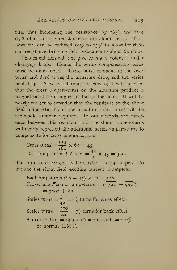
ELEMENTS OF DYNAMO DESIGN 21
3
rise, thus increasing the resistance by 16%, we have
65.8 ohms for the resistance of the shunt fields. This,
however, can be reduced 10% to 15% to allow for rheo-
stat resistance, bringing field resistance to about 60 ohms.
This calculation will not give constant potential under
changing loads. Hence the series compensating turns
must be determined. These must compensate the cross
turns, and back turns, the armature drop, and the series
field drop. Now by reference to Sec. 55 it will be seen
that the cross ampere-turns on the armature produce a
magnetism at right angles to that of the field. It will be
nearly correct to consider that the resultant of the shunt
field ampere-turns and the armature cross turns will be
the whole number required. In other words, the differ-
ence between this resultant and the shunt ampere-turns
will nearly represent the additional series ampere-turns to
compensate for cross magnetization.
Cross turns = —^— X 60 = 4c;.'
44Cross amp.-turns \ I X ne = — X 45 = 990.
The armature current is here taken as 44 amperes to
include the shunt field exciting current, 2 amperes.
Back amp.-turns (60 — 45) X 22 = 330.f ' 2 1
Cross. mag.rcomp. amp.-turns = (9792" + ggo")^
= 9792 + 50.
Series turns = — = 1 i turns for cross effect.42
F
Series turns = ^— = 7f turns for back effect.42
Armature drop = 44 X 0.06 = 2.64 volts = 2.2 c/
of normal E.M.F.
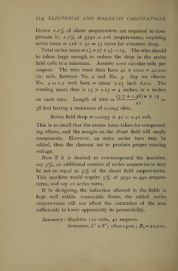
214 ELECTRICAL AND MAGNETIC CALCULATIONS.
Hence 2.2% of shunt ampere-turns are required to com-
pensate it; 2.2% of 9792 = 216 ampere-turns, requiring
series turns = 216-7-42 = Sj turns for armature drop.
Total series turns= 1^+ 71+51=15. The wire should
be taken large enough to reduce the drop in the series
field coils to a minimum. Assume 1000 circular mils per
ampere. The wire must then have 42 x 1000 = 42,000
cir. mils, between No. 4 and No. 3. Say we choose
No. 4 = 0.2 inch bare = about 0.25 inch d.c.c. Thewinding space then is 15 X 0.25 = 4 inches, or 2 inches
t. t 4.1, * • (7-7 + 1.98) ir X 15on each core. Length of wire = ^^—- ^ =
38 feet having a resistance of 0.0095 ohm.
Series field drop = 0.0095 X 42 = 0.40 volt.
This is so small that the excess turns taken for compound-
ing effects, and the margin on the shunt field will amply
compensate. However, an extra series turn may be
added, then the rheostat set to produce proper running
voltage.
Now if it is desired to overcompound the machine,
say 5 °f , an additional number of series ampere-turns may
be put on equal to 5 % of the shunt field ampere-turns.
This machine would require 5% of 9792 = 490 ampere-
turns, and say 12 series turns.
If in designing, the induction allowed in the fields is
kept well .within reasonable limits, the added series
ampere-turns will not affect the saturation of the iron
sufficiently to lower appreciably its permeability.
Summary : Machine 120 volts, 42 amperes.
Armature, 8" X 8"; 1800 r.p.m. ; Ba= 10,000.
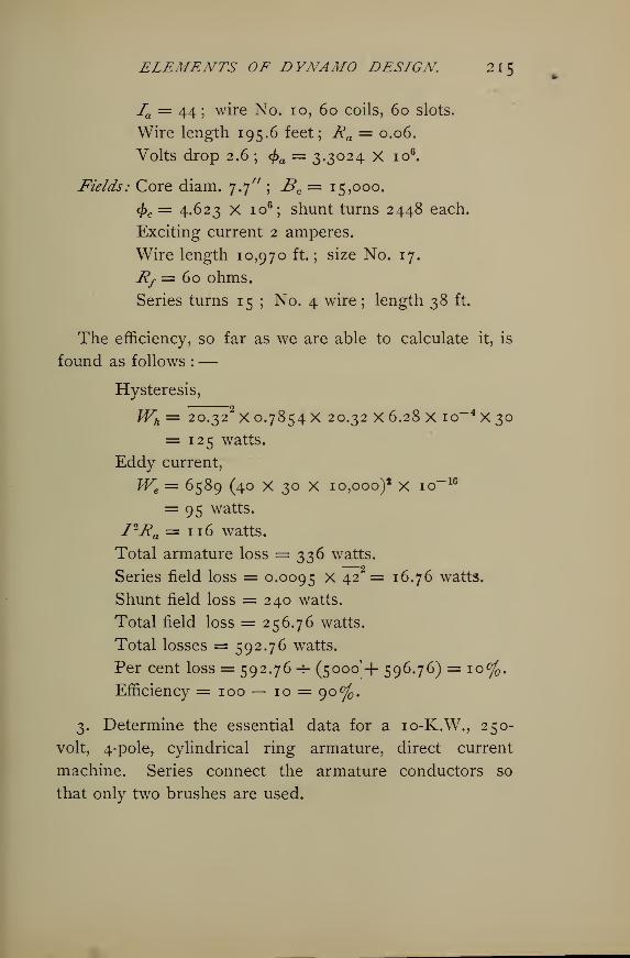
ELEMENTS OF DYNAMO DESIGN 21 5
Ia — 44; wire No. 10, 60 coils, 60 slots.
Wire length 195.6 feet; Ra = 0.06.
Volts drop 2.6 ; <j>a = 3.3024 X io6.
Fields: Core diam. 7.7" ; Bc== 15,000.
<£c = 4.623 X io6; shunt turns 2448 each.
Exciting current 2 amperes.
Wire length 10,970 ft. ; size No. 17.
Rf = 60 ohms.
Series turns 15 ; No. 4 wire ; length 38 ft.
The efficiency, so far as we are able to calculate it, is
found as follows :—
Hysteresis,
Wh = 20.322X 0.7854 X 20.32 X 6.28 X io
-4 X 30
= 125 watts.
Eddy current,
We= 6589 (40 X 30 X 10,000)* X io-16
= 95 watts.
I2jRa =116 watts.
Total armature loss = 336 watts.
Series field loss = 0.0095 X 42 = 16.76 watts.
Shunt field loss = 240 watts.
Total field loss = 256.76 watts.
Total losses = 592.76 watts.
Per cent loss = 592.76 -4- (5000'+ 596.76) = 10%.Efficiency = 100— 10 = 90%.
3. Determine the essential data for a 10-K.W., 250-
volt, 4-pole, cylindrical ring armature, direct current
machine. Series connect the armature conductors so
that only two brushes are used.
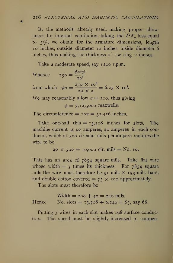
2l6 ELECTRICAL AND MAGNETIC CALCULATIONS.
By the methods already used, making proper allow-
ances for internal ventilation, taking the I2Ra loss equal
to 3%, we obtain for the armature dimensions, length
10 inches, outside diameter 10 inches, inside diameter 6
inches, thus making the thickness of the ring 2 inches.
Take a moderate speed, say 1200 r.p.m.
$nvpWhence 250 =
10"
v8r , • ,
2 50 X IO C
from which d>n = ~ = 6.2 q X io8.^ 20 X 2
°
We may reasonably allow n = 200, thus giving
<£ = 3,125,000 maxwells.
The circumference = i07r= 31.416 inches.
Take one-half this = 15.708 inches for slots. Themachine current is 40 amperes, 20 amperes in each con-
ductor, which at 500 circular mils per ampere requires the
wire to be
20 X 500 = 10,000 cir. mils = No. 10.
This has an area of 7854 square mils. Take flat wire
whose width = 3 times its thickness. For 7854 square
mils the wire must therefore be 51 mils X 153 mils bare,
and double cotton covered = 75 X 200 approximately.
The slots must therefore be
Width = 200 + 40 = 240 mils.
Hence No. slots = 15.708 -5- 0.240 = 65, say 66.
Putting 3 wires in each slot makes 198 surface conduc-
tors. The speed must be slightly increased to compen-
ELEMENTS OF DYNAMO DESIGN 21J
sate for the two conductors dropped ; otherwise carry
the field magnetization slightly higher.
Depth of wire = 3 X 75 = 225 mils; allow 100 mils
for insulation in the bottom of the slots, thus requiring
the depth to be 325 mils.
Exact width of each slot will be
31.416 -h (66 X 2) = 0.238 inch.
This is also the width of each tooth.
The approximate length of wire will be
66[(io + io + 2 + a)+6] = i6Sj say i?5^No. 10 has 1.023 ohms per 1000 feet; hence
_ (1.023 X 0.175) + 16% of (1.023 X 0.175)
4= 0.0525 ohm.
Allowing 0.1 inch clearance, the pole circle will have
a diameter
D = 10 + 0.2 =10.2 inches, and
Circum. = io.27r = 32 inches.
Making the width of the poles equal to their distance
apart, we have
Pole width 32 -r- 8 = 4 inches.
Pole face length =10 inches.
Area pole face = 10 x 4 = 40 sq. in. = 250 sq. cms.
Pole flux, perhaps, 3.125 x io6 X 1.25 = 4 X io6
maxwells.
Bp = 4 x io6 -r25o= 16,000 gausses.
2l8 ELECTRICAL AND MAGNETIC CALCULATIONS.
This intensity may be reduced by making the width of
the pole face slightly greater. To determine approxi-
mately the field winding. Take the length of poles =6 inches = 15.24 cms. Also
rr^i • 1 r f (4 X IO6) "f" 12,000
Thickness of pole ring = — '- = 7 cms.v & 10X2.54 '
= 2.5 inches.
Mean circum. of ring (5.1 + 6+ 1^) X 2ir X 2.54 = 197 cms.
Length of flux travel in pole ring is
/= £ of 197 = 49 cms.
For curving down to enter poles add 3 + 3=6 cms.
making 55 centimeters.
Armature, Norway iron, /= 10" = 25.4 cms., for lines.
Area, A = (10 X 2.54) X (2 X 2.54) = 129 sq. cms.
_ 3.125 X io6
Ba= '- 129 = 12,100 gausses.
O.OOOI ,
k = = 0.00035 oersted per cc.1 — 0.000059 X 12,100
2 C.4.(R_ = 0.00035 x -^— = 0.00006 oersted.
129
Air gaps, length, / = 0.2 inch = 0.508 cm.
A A 2 5°Area, A = -^— = 125 sq. cms.
^ 0.C08(R„ = —-— = 0.004 oersted.
125
Cores, wrought iron, /= 15.25 cms.
A = -^- = 125 sq. cms.
ELEMENTS OF DYNAMO DESIGN. 2K)
4 X io6
Br = = 16,000 gausses.c2 X 125
&
0.0004 i
k = — = 0.004 c oersted per cc.1 — 0.000057 X 16,000
j c 2 c X 2(ft = 0.0041: X = 0.0011 oersted.3
125
Yoke3/= 55 cms.
A = 175 sq. cms.
4 X io4
By= 5- 175 = 11,400 gausses.
_ 0.0004# = = 0.00 1 14 oersted per cc.
1—0.000057X11,400
(fty= 0.00144 X = 0.00045 oersted.
Reluctance of a single circuit is
(ft = 0.00006 + 0.004 + 0.0011 + 0.00045
= 0.0056 oersted.
Of two circuits in parallel the reluctance is
(ft = 0.0028 oersted.
M.M.F. = 0.0028 x 3.125 x io6 = 8750 gilberts.
Ampere-turns, each core, = —^
—
"-— = 3483.
Exciting current Is= 3.5% of 40 = 1.5 amperes.
Hence
n = 2322, say 2325 turns, each core.
Total turns, n = 2325 x 4 = 9300.
2 CORf = —— = 166.6 ohms = 41.6 ohms each core.1.5
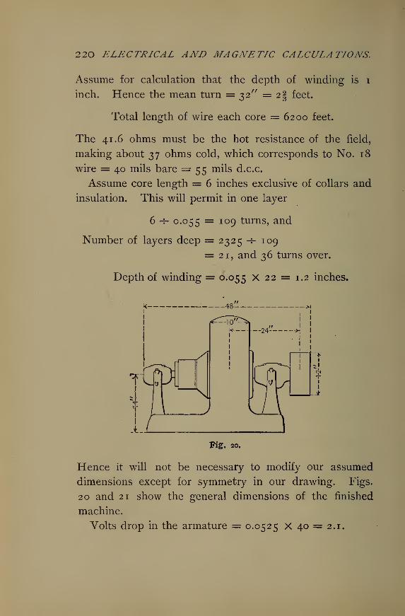
220 ELECTRICAL AND MAGNETIC CALCULATIONS.
Assume for calculation that the depth of winding is i
inch. Hence the mean turn = 32" = 2§ feet.
Total length of wire each core = 6200 feet.
The 41.6 ohms must be the hot resistance of the field,
making about 37 ohms cold, which corresponds to No. 18
wire = 40 mils bare = 55 mils d.c.c.
Assume core length = 6 inches exclusive of collars and
insulation. This will permit in one layer
6 -5- 0.055 = 109 turns, and
Number of layers deep = 2325-7-109
= 21, and 36 turns over.
Depth of winding = 0.055 X 22 = 1.2 inches.
-48-
A_J
A
Fig. 20.
Hence it will not be necessary to modify our assumed
dimensions except for symmetry in our drawing. Figs.
20 and 21 show the general dimensions of the finished
machine.
Volts drop in the armature = 0.0525 X 40 = 2.1.
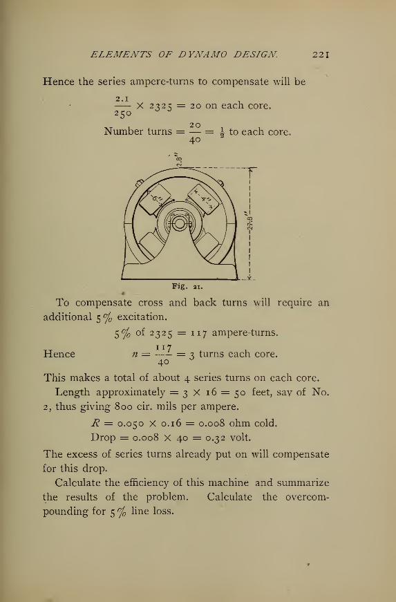
ELEMENTS OF DYNAMO DESIGN 221
Hence the series ampere-turns to compensate will be
2.1 .
X 2325 = 20 on each core.250
Number turns = — = ^ to each core.40
2
Fig. ax.»
To compensate cross and back turns will require an
additional 5 % excitation.
5% of 2325 = 117 ampere-turns.
HenceIX 7
n = —- = 3 turns each core.40
6
This makes a total of about 4 series turns on each core.
Length approximately = 3 X 16 = 50 feet, sav of No.
2, thus giving 800 cir. mils per ampere.
R = 0.050 X 0.16 = 0.008 ohm cold.
Drop = 0.008 x 40 = 0.32 volt.
The excess of series turns already put on will compensate
for this drop.
Calculate the efficiency of this machine and summarize
the results of the problem. Calculate the overcom-
pounding for 5 % line loss.
222 ELECTRICAL AND MAGNETIC CALCULATIONS.
4. Determine the data for a \ H.P. bipolar motor for
112 volts direct current.
In this design we shall express our dimensions in inches,
and make use of table 13 and the curves in table 9 in
order to illustrate their application.
We have seen that reluctance
(R = ^- = — • Also, (114)a a/jL
nl= = 7 = - • (115)1.256 1.256 a/xX 1.256 x oy
Here / is expressed in centimeters and a in square centi-
meters. Now, if these dimensions are expressed in inches
and square inches, the numerator of the fraction must be
multiplied by 2.54, and the denominator multiplied by
6.45. Introducing these values in the equation it becomes
nf= <ft X / X 2 -54 = Q-3I3 2 X / X <fr
"1.256 X a X /x X 6.45
"
a/ji ^ '
This gives the ampere-turns for any one portion of the
magnetic circuit. So that knowing / and a we have only
to determine fi from the flux density by reference to tables
13 and 9.
For \ H.P. at 112 volts the current required will be
about 2 amperes, or one ampere in each armature con-
ductor. For so small a machine we shall allow ample
cross section in the armature conductors and select No.
21, having 810 circular mils, diameter 0.034 in„, double
cotton covered. Calculations as before, also reasonable
assumptions for an armature of this power will give a
diameter of about 3 inches. Take a length of 3 inches.
Then for a speed of, say 2400 r.p.m., and say 16 slots
ELEMENTS OE DYNAMO DESIGN 22$
holding 6 wires in width and 9 deep, or 54 wires each,
and 54 X 16= 864 conductors total, the required armature
flux will be io8 X 112
^=4ox864 =324'°74maXWells -
This will make B about 60,000 per square inch. Making
proper allowances for the insulation, the slots must be f
inch wide by \ inch deep. Therefore the cross sectional
area of the body of armature iron is
3 * [3 — (I + f)] = 4.875 square inches,
since the shaft will be f inch and the depth of two teeth
is f inch. This will make the density
324,074 -f- 4.875 = 66,476.
The length of the flux lines in the armature body will be
about 1.75 inches.
The width of teeth at the top = 0.3125 inch; at the
bottom, 0.1875 inch; average, 0.25 inch.
Area = 0.25 X 3 X 6 = 4.5 sq. in.
The density in the teeth = 324,074 -*- 4.5 = 72,016 lines
per square inch. The average width of the tuft of lines
entering each tooth, experience teaches, will be the width
of the top of tooth plus the length of the air gap. Hence
with 6 teeth under the pole at a time the air gap area
will be(o.3I2 5 + 0.062) x 3 X 6 = 6.741 sq. in.
The field flux will be, say 324,074 x 1.1 = 356,481.
We shall make the field rectangular in shape with in-
wardly projecting horizontal poles. Make the poles
square in cross section with slightly rounded corners,
say 9 square inches area. The pole density will be
224 ELECTRICAL AND MAGNETIC CALCULATIONS.
356,481 -r- 9 = 39,609. Allow the wire to wind deeper in
this small machine and shorten the poles so that about i-J-
inches will be its depth. This will require about 1^- inches
length of winding space. Adding \ inch each for collars
makes if inches for length of poles, say ij7^ inches to
allow for portion outside of coil.
From the poles the lines of force will have two parallel
paths, and so the cross section of the yoke frame need
be only one-half that of the poles. It will be 3 inches
wide, of course, requiring a thickness of yoke of i-J- inches.
We shall now have between ends of field coils 3+ tV+ tV
+ \ = 3^ inches. From center of yoke on one side
through field coil, air gaps, field coil to center of yoke on
the opposite side i|- + i| + 3i + i| = 8| inches. The
height from center of horizontal portion of yoke (base)
at the bottom to center of horizontal yoke at the top
about 7f inches. The over-all length of the rectangle
through the poles and armature will be 8^ + i-J- = 9Iinches. Over all height = j% + 1% = g£ inches.
We may now summarize and calculate the ampere-turns
required for cast iron fields and wrought iron armature.
Armature : I =1.75 inches; A = 4.875 square inches.
fx, from table 13 for density = 66,475
= 10,300 per sq. cm., is about 2000;
1 r B 10,300also from o, u = -== = —-
—
y B 5= 2000.
0.3132 X / X <f>
a a ft
= 18.
a X fji
0.3132 X 1.75 X 324,074
4.875 X 2000
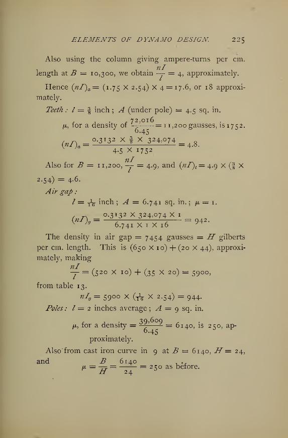
ELEMENTS OF DYNAMO DESIGN 225
Also using the column giving ampere-turns per cm.
11
T
length at B = 10,300, we obtain —- = 4, approximately.
Hence (nf)a = (1.75 X 2.54) X 4 = 17.6, or 18 approxi-
mately.
Teeth : I = § inch ; A (under pole) = 4.5 sq. in.
r 72,Ol6fx, for a density of — =11,200 gausses, is 1752.
= 0.3132 x I x 324,074 = _
V ,a4.5 X 1752
Also for B = 11,200, — = 4.9, and (nf)t= 4.9 X (f X
2.54) = 4.6.
Air gap :
I = y1^ inch ; ^4 = 6.741 sq. in.
;/x = 1.
/ n 0.3132 X 324,074 X 1
(nI)Q= = 942.v Jg
6.741 X 1 X 16 ^The density in air gap = 7454 gausses = H gilberts
per cm. length. This is (650 X 10) + (20 X 44), approxi-
mately, making
— = (520 x 10) + (35 X 2 °) = 59°°>
from table 13.
nI9 = 59°° X (A X 2.54) = 944.
Poles : I = 2 inches average ; A = 9 sq. in.
r i • 3Q>6oo/a, for a density = ^ = 6140, is 250, ap-
proximately.
Also from cast iron curve in 9 at B = 6140, H = 24,
and B 6140 , ..u, = -== = = 2 co as before.r ZT 24 °
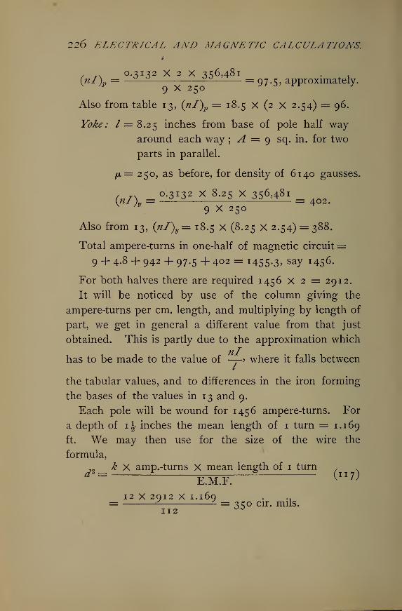
226 ELECTRICAL AND MAGNETIC CALCULATIONS.
/ rN °-3 I 3 2 X 2 X 3^6,481 . .
(nl)p= = 97-5> approximately.
Also from table 13, (nl)p = 18.5 X (2 X 2.54) = 96.
P^; /=8.25 inches from base of pole half way
around each way ; A = 9 sq. in. for two
parts in parallel.
fiz= 250, as before, for density of 6140 gausses.
= 0.3132 x 8.25 x 356,481 =.
9 X 250
Also from 13, (nl)y= 18.5 X (8.25 X 2.54) = 388.
Total ampere-turns in one-half of magnetic circuit =9 + 4.8 + 942 + 97.5 +402 = i455-3> saY ^S 6 -
For both halves there are required 1456 X 2 = 2912.
It will be noticed by use of the column giving the
ampere-turns per cm. length, and multiplying by length of
part, we get in general a different value from that just
obtained. This is partly due to the approximation whichTil
has to be made to the value of —-> where it falls between
the tabular values, and to differences in the iron forming
the bases of the values in 13 and 9.
Each pole will be wound for 1456 ampere-turns. For
a depth of \\ inches the mean length of 1 turn = 1.169
ft. We may then use for the size of the wire the
formula,
2 __ k X amp.-turns X mean length of 1 turn"E.M.F. ^
II7^
12 X 2012 X 1. 160 . „= = ^co cir. mils.112 ^
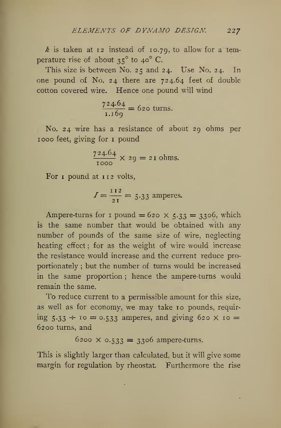
ELEMENTS OF DYNAMO DESIGN 227
k is taken at 12 instead of 10.79, to aU°w f°r a tem-
perature rise of about 35 to 40 C.
This size is between No. 25 and 24. Use No. 24. In
one pound of No. 24 there are 724.64 feet of double
cotton covered wire. Hence one pound will wind
724.64— = 620 turns.1. 169
No. 24 wire has a resistance of about 29 ohms per
1000 feet, giving for 1 pound
724.64x 29 = 21 ohms.
1000
For 1 pound at 1 1 2 volts,
I=— = 5.33 amperes.
Ampere-turns for 1 pound =620 x 5.33 = 3306, which
is the same number that would be obtained with any
number of pounds of the same size of wire, neglecting
heating effect ; for as the weight of wire would increase
the resistance would increase and the current reduce pro-
portionately ; but the number of turns would be increased
in the same proportion ; hence the ampere-turns would
remain the same.
To reduce current to a permissible amount for this size,
as well as for economy, we may take 10 pounds, requir-
ing 5*33 ~^ IO = °-533 amperes, and giving 620 X 10 =6200 turns, and
6200 X 0.533 = 3306 ampere-turns.
This is slightly larger than calculated, but it will give some
margin for regulation by rheostat. Furthermore the rise
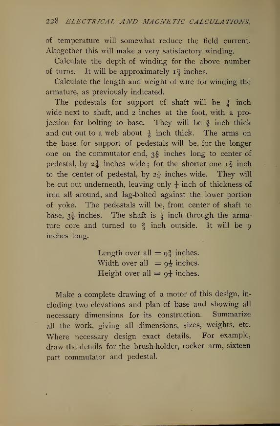
228 ELECTRICAL AND MAGNETIC CALCULATIONS.
of temperature will somewhat reduce the field current.
Altogether this will make a very satisfactory winding.
Calculate the depth of winding for the above number
of turns. It will be approximately i| inches.
Calculate the length and weight of wire for winding the
armature, as previously indicated.
Th,e pedestals for support of shaft will be f inch
wide next to shaft, and 2 inches at the foot, with a pro-
jection for bolting to base. They will be | inch thick
and cut out to a web about \ inch thick. The arms on
the base for support of pedestals will be, for the longer
one on the commutator end, 3! inches long to center of
pedestal, by 2^ inches wide; for the shorter one i|- inch
to the center of pedestal, by 2^ inches wide. They will
be cut out underneath, leaving only J inch of thickness of
iron all around, and lag-bolted against the lower portion
of yoke. The pedestals will be, from center of shaft to
base, 3^ inches. The shaft is f inch through the arma-
ture core and turned to | inch outside. It will be 9
inches long.
Length over all = 9I inches.
Width over all = 9^ inches.
Height over all = 9^ inches.
Make a complete drawing of a motor of this design, in-
cluding two elevations and plan of base and showing all
necessary dimensions for its construction. Summarize
all the work, giving all dimensions, sizes, weights, etc.
Where necessary design exact details. For example,
draw the details for the brush-holder, rocker arm, sixteen
part commutator and pedestal.
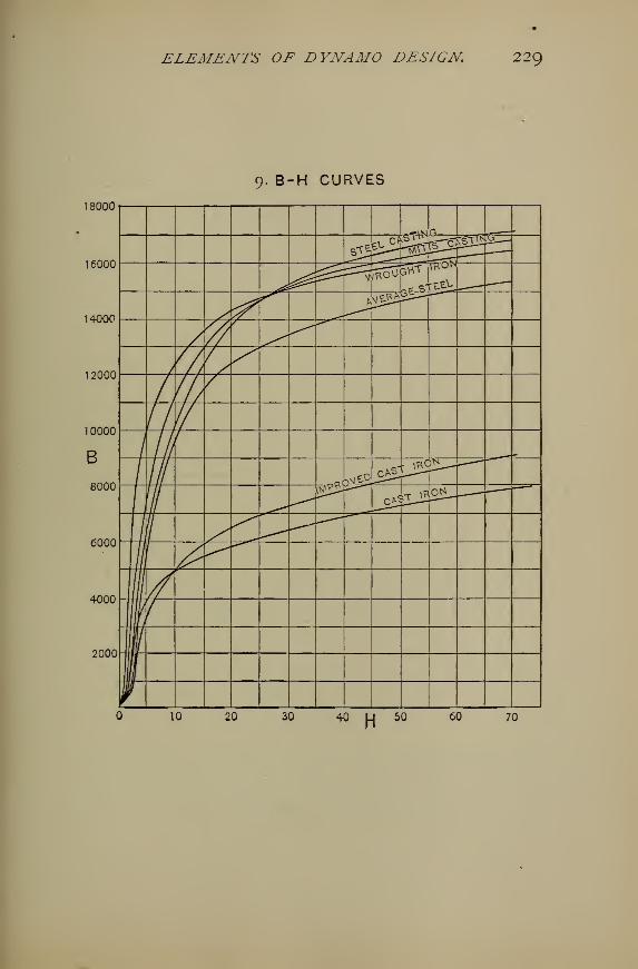
ELEMENTS OF DYNAMO DESIGN 229
9. B-H CURVES
18000
16000
14000
12000
10000
B
8000
6000
4000
2000
^2<0.ev^ §3 £§!!£
(j
^VfrOV 3HT ikon
y,fs
VVe^
7//
'/,{/ s
/ J'/
L If
/ 1
/ \ y0.eg.LJ22^
/,
III0^-
j£piS0^
1
I1I1
10 20 30 40 U 50 60 70H
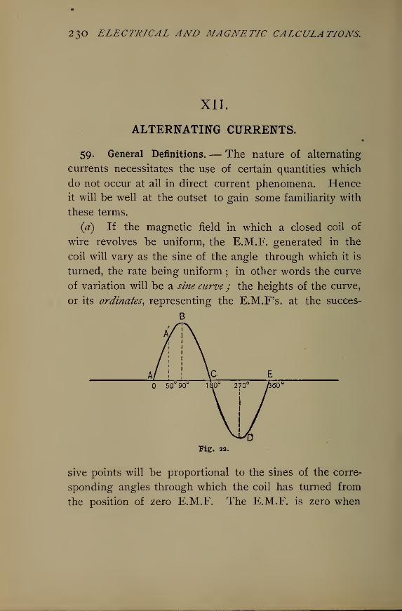
23O ELECTRICAL AND MAGNETIC CALCULATIONS.
XII
ALTERNATING CURRENTS.«
59. General Definitions.— The nature of alternating
currents necessitates the use of certain quantities which
do not occur at all in direct current phenomena. Henceit will be well at the outset to gain some familiarity with
these terms.
(a) If the magnetic field in which a closed coil of
wire revolves be uniform, the E.M.F. generated in the
coil will vary as the sine of the angle through which it is
turned, the rate being uniform ; in other words the curve
of variation will be a sine curve ; the heights of the curve,
or its ordinates, representing the E.M.F's. at the succes-
B
Fig. 22.
sive points will be proportional to the sines of the corre-
sponding angles through which the coil has turned from
the position of zero E.M.F. The E.M.F. is zero when
ALTERNATING CURRENTS. 23 I
the plane of the loop is perpendicular to the lines of
magnetic force. Fig. 22 shows the sine curve. Dis-
tances measured horizontally represent angles, distances
vertically represent E.M.F's.
The height of the curve A r above the horizontal line
represents the E.M.F. in the coil when revolved 50 from
the position when the plane of the coil is normal to the
lines of force. The height at B is proportional to the
E.M.F. at 90 , or in the position when the coil's plane is
parallel with the lines of magnetic force. This is clearly
the position of maximum positive E.M.F. Therefore
KM.F. at A' sin 50
E.M.F. at B "=sin 90
"
Hence the name sine curve.
(p) It is clear from the curve that the average E.M.F.
during one-half a revolution, or one alternation, is pro-
portional to the average ordinate of the curve. Call the
maximum ordinate at 90 one, then the area of the curve
between the horizontal line and ABC is 2. The length
AC = 180 = 7r = 3.1416. Therefore the average ordi-
nate is
area 2/: c ^
i r= - = 0.637 of the maximum.length 7T
0/
Therefore, calling the maximum E.M.F. E, and the
average E.M.F. Ea , we have
Ea =o.637E. (118)
Suppose the maximum pressure be 100 volts, then the
average pressure will be.
Ea — 0.637 x IO° =63.7 volts.
232 ELECTRICAL AND MAGNETIC CALCULATIONS.
(c) The effective pressure of alternators is some greater
than the average, and is that which is available for pro-
ducing heat if applied to a resistance. The effective
pressure is the square root of the mean of the squares of
the successive pressures during one-half a revolution of
the pressure coil, because the successive heats are pro-
portional to the successive i?2's. The E.M.F's. vary from
zero to i as a maximum. Therefore the mean of the
squares is, by adding the squares of say 12 ordinates,
and dividing by 12, J.
Its square root isJI _ JL = 0.707 of the maximum.T 2 V2
Calling the effective E.M.F. Ee , we have
Ee = O.707 E. (119)
For a maximum pressure of 100 volts the effective E.M.F.
will be (that indicated by a voltmeter)
Ee= 0.707 X 100 = 70.7 volts.
(d) The period of an alternating current is the time
from A in Fig. 22 to E, or the complete cycle, or one
complete revolution of the coil in a 2-pole machine.
The number of complete periods per second is the fre-
quency of the current. A cycle consists of two alterna-
tions, or reversals of current. Therefore a frequency of
125 per second means 125 X 2 = 250 alternations per
second. The frequency of practical machines in the
U. S. will nearly always be 60 or 25 per second, although
125, 40, 66, 100 and 133 are used. A 4-pole machine
gives a frequency equal to twice the number of revo-
lutions per second; an 8-pole, 4 times the number.
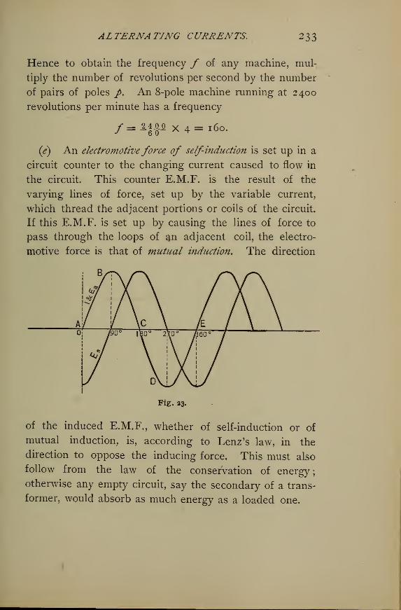
ALTERNATING CURRENTS. 233
Hence to obtain the frequency f of any machine, mul-
tiply the number of revolutions per second by the number
of pairs of poles p. An 8-pole machine running at 2400
revolutions per minute has a frequency
/= 2ioo X4=l6o .
(e) An electromotive force of self-induction is set up in a
circuit counter to the changing current caused to flow in
the circuit. This counter E.M.F. is the result of the
varying lines of force, set up by the variable current,
which thread the adjacent portions or coils of the circuit.
If this E.M.F. is set up by causing the lines of force to
pass through the loops of an adjacent coil, the electro-
motive force is that of mutual induction. The direction
Fig. 23.
of the induced E.M.F., whether of self-induction or of
mutual induction, is, according to Lenz's law, in the
direction to oppose the inducing force. This must also
follow from the law of the conservation of energy;
otherwise any empty circuit, say the secondary of a trans-
former, would absorb as much energy as a loaded one.
234 ELECTRICAL AND MAGNETIC CALCULATIONS.
Since E.M.F. is proportional to the rate of change of the
number of lines of force threading any circuit or loop, the
self-induced pressure is the greatest when the alternating
current is the least, or zero, and vice versa. Although at
its maximum value the current sets up the maximumnumber of lines, the rate of change of the lines is the
least ; while at zero current and lines the rate of change
is a maximum, hence the induced E.M.F. is a maximum.
A reference to Fig. 23 will make clear the relative
values of the inducing current and E.M.F. of self-induc-
tion at successive instants. It will be observed that the
E.M.F. of self-induction Es lags 90 behind the curve of
current and active E.M.F., Ea . For an instant at B and
D there is no change in the current, hence no induced
E.M.F., while the change is most rapid through C and Eshown by the slope of the curve, and hence there is a
maximum counter E.M.F. at these points.
CO Whenever an alternating pressure is applied to a
circuit a certain component of it is useful to send the cur-
rent through the resistance. This component is called
the active pressure. The other component at right angles
to the first goes to balance the E.M.F. of self-induction
set up by the alternating current; this is sometimes
called simply the self-induction pressure. The total ap-
plied E.M.F is called simply the impressedpressure. This
is analogous to a vessel moving, say N. of E. at a given
impressed speed. It will be going east at a certain speed
which we may call the active speed. We may suppose,
in fact, the desired course is E., but on account of adverse
currents or winds, the counter pressure, it has to steer N.
of E. It will at the same time be moving north at a cer-
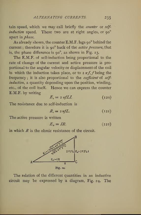
ALTERNATING CURRENTS. 235
tain speed, which we may call briefly the counter or self-
induction speed. These two are at right angles, or 90
apart in phase.
As already shown, the counter E.M.F. lags 90 behind the
current ; therefore it is 90 back of the active pressure, that
is, the phase difference is 90 , as shown in Fig. 23.
The E.M.F. of self-induction being proportional to the
rate of change of the current and active pressure is pro-
portional to the angular velocity or displacement of the coil
in which the induction takes place, or to 2 7r/,/ being the
frequency ; it is also proportional to the coefficient of self-
induction, a quantity depending upon the position, winding,
etc., of the coil itself. Hence we can express the counter
E.M.F. by writing
Es =2irfLL (120)
The resistance due to self-induction is
R$= 27T/Z.
The active pressure is written
Ea = IR.
in which R is the ohmic resistance of the circuit.
(121)
(122)
Fig. 24.
The relation of the different quantities in an inductive
circuit may be expressed by a diagram, Fig. 24. The
236 ELECTRICAL AND MAGNETIC CALCULATIONS.
counter E.M.F. is represented by the vertical CB, and the
active by AC, the impressed E{being the hypotenuse of
the triangle of which the two components Ea and Es are
the two perpendicular sides.
The angle BAC is the angle of lag of the current and
active pressure behind the impressed pressure AB,which is
^,= /V^2+ 4 7ry2Z2
. (123)
This is Ohm's law applied to alternating currents.
Transposing this so as to put it in the usual form, we have
for current in alternating current circuits,
If L = o, then 1= — as in direct current circuits. 2 irfKis often represented by a>, the angular velocity ; in which
case (124) would be written
-wi + ^jr- (I2 5)
(g) If the values of the various E.M.F's. in Fig. 24 be
divided by I, the current, the quotients will be the equiva-
lent resistances as shown inside the diagram. R is the
metallic or ohmic resistance ; 2 irfL is the inductive resis-
tance, or reactance ; V47r2%
/*2Z2 + i?2 is the apparent re-
sistance or impedance. The hypotenuse, of course, is the
square root of the sum of the squares of the two sides.
( h ) In the above equations L is the coefficient of self-
induction, a constant for any given circuit without iron. It
is defined as the E.M.F. induced in a circuit wholly free
ALTERNATING CURRENTS. 237
from iron or other magnetic material, when the curre?it varies
at the rate of one ampere per second. It is also called the
inductance of the circuit. The unit of inductance is the
henry, or that of 1 volt of counter E.M.F. when the current
changes at the rate of 1 ampere per second. The henry
= io9 C.G.S. units of inductance.
(*) The capacity of an alternating current circuit is
the measure of the amount of electricity held by it when
its terminals are at unit difference of potential. Every
such circuit acts as a condenser, and a current will flow
back and forth, even though it is open and in the ordinary
sense unloaded, proportional to the rate of change of the
active pressure of the circuit, and to the capacity of the
circuit. The effect of capacity is directly opposite to self-
induction. Hence by properly arranging the capacity
of a circuit it is possible to neutralize inductance, and so
to bring the alternating current under the same laws as
direct. If /be the frequency and Ec the pressure at any
moment applied to a condenser, or circuit whose con-
denser capacity is C, the current flowing back and forth
due to this capacity is
I=2TrfCEc . (126)
and E< = 7^fC'
(I2?)
In this case the resistance due to capacity is
Ec may be called the capacity pressure which is opposite to
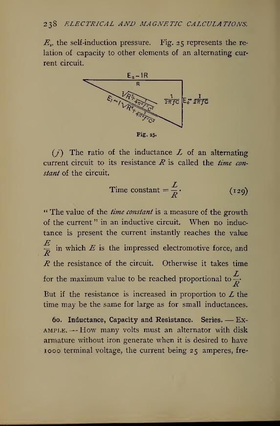
238 ELECTRICAL AND MAGNETIC CALCULATIONS.
JSsythe self-induction pressure. Fig. 25 represents the re-
lation of capacity to other elements of an alternating cur-
rent circuit.
£~zwjo
(/) The ratio of the inductance L of an alternating
current circuit to its resistance R is called the time con-
stant of the circuit.
Rm
(I29)
Time constant
" The value of the time constant is a measure of the growth
of the current " in an inductive circuit. When no induc-
tance is present the current instantly reaches the value
— in which E is the impressed electromotive force, andRR the resistance of the circuit. Otherwise it takes time
Lfor the maximum value to be reached proportional toRBut if the resistance is increased in proportion to L the
time may be the same for large as for small inductances.
60. Inductance, Capacity and Resistance. Series.— Ex-
ample.— How many volts must an alternator with disk
armature without iron generate when it is desired to have
1000 terminal voltage, the current being 25 amperes, fre-
ALTERXATIXG CURRENTS. 239
quency 100 cycles per second, resistance 1 ohm, and
coefficient of inductance L = 0.01 henry ?
—
Jackson.*
Solution. — Reference to Fig. 24 and formula (120; will
give for the E.M.F. of self-induction
Es= 2-jt/LI = 27r X 100X0.01 x 25 = 157 volts.
The active pressure from (122) will be
Ea = IR = 25 x 1 = 25 volts,
The external required voltage is 1000 volts. Therefore
the total active pressure becomes
Ea = 25 + 1000 =1025 volts.
Hence the impressed pressure to be developed by the
alternator is from (123)
E{= \IE?+Ea*= V^+T^ 2 = I037 volts.
Example.— How many more volts than in the preced-
ing case must be generated in the armature of the above
machine if iron be used in the core so that when carry-
ing 25 amperes the inductance is 0.025 henry ?
Solution.— As before the total active pressure is
Ea = 1000 + 25 = 1025 volts,
and Es = 27r x 100 x 0.025 x 2 5 = 39 2 -7 volts.
Therefore the total impressed E.M.F. must be2 s
1025" + 392.7" = 1098 volts,
or 1098 — 1037 = 61 volts higher pressure than before.
When two or more inductances are in series, and have
equal time constants, that is, if
E1 R2 Rz
* See Jackson's A Iternating Cnrrenti, p. 75,
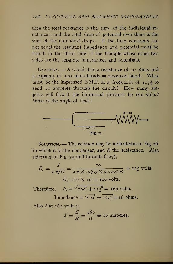
240 ELECTRICAL AND MAGNETIC CALCULATIONS.
then the total reactance is the sum of the individual re-
actances, and the total drop of potential over them is the
sum of the individual drops. If the time constants are
not equal the resultant impedance and potential must be
found in the third side of the triangle whose other two
sides are the separate impedances and potentials.
Example. — A circuit has a resistance of 10 ohms and
a capacity of ioo microfarads = 0.000100 farad. Whatmust be the impressed E.M.F. at a frequency of 127 \ to
send 10 amperes through the circuit? How many am-
peres will flow if the impressed pressure be 160 volts?
What is the angle of lead ?
R-10
A/WWV^C = 100
Fig. 26.
Solution.— The relation may be indicated as in Fig. 26,
in which C is the condenser, and R the resistance. Also
referring to Fig. 25 and formula (127),
Ec = -^ = = 125 volts.2 7T/C 2 7T X I27.5 X 0.000I00
En = io X 10 = 100 volts.
Therefore, E{= v ioo
2 + 1252 = 160 volts.
Impedance = V7o + 12.5 = 16 ohms.
Also /at 160 volts is
r E 160I = — = —t- = 10 amperes.K 16
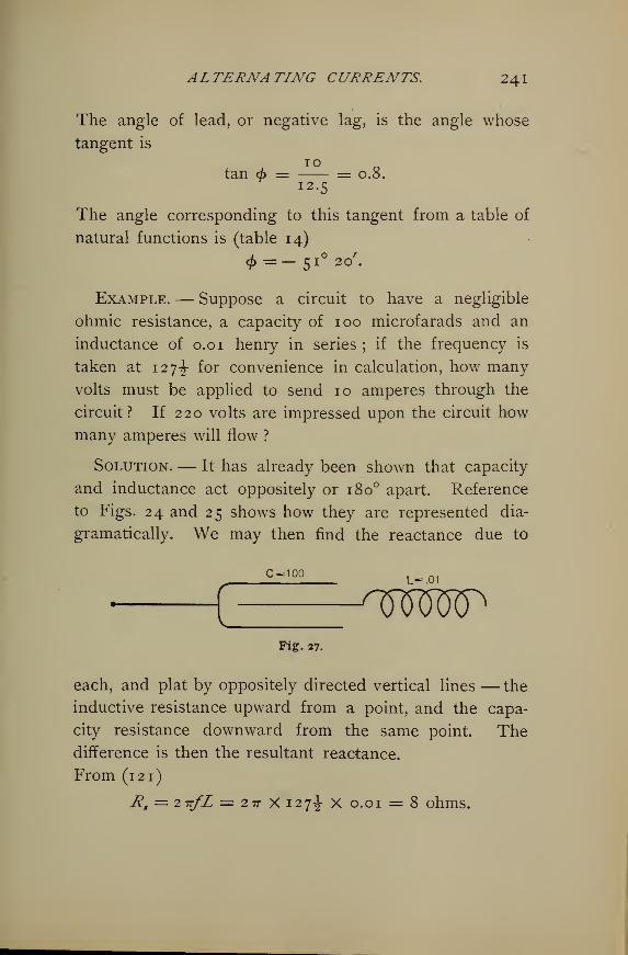
ALTERNATING CURRENTS. 24
1
The angle of lead, or negative lag, is the angle whose
tangent is
10tan d> = = 0.8.
12.5
The angle corresponding to this tangent from a table of
natural functions is (table 14)
<£=- 51° 20'.
Example.— Suppose a circuit to have a negligible
ohmic resistance, a capacity of 100 microfarads and an
inductance of 0.0 1 henry in series ; if the frequency is
taken at 127^- for convenience in calculation, how many
volts must be applied to send 10 amperes through the
circuit? If 220 volts are impressed upon the circuit how
many amperes will flow ?
Solution.— It has already been shown that capacity
and inductance act oppositely or 180 apart. Reference
to Figs. 24 and 25 shows how they are represented dia-
gramatically. We may then find the reactance due to
C ° 100L-JD1
sWMPFig. 27.
each, and plat by oppositely directed vertical lines — the
inductive resistance upward from a point, and the capa-
city resistance downward from the same point. Thedifference is then the resultant reactance.
From (121)
R8= 2-rrfL = 2 7r X 127^- x 0.01 = 8 ohms.
242 ELECTRICAL AND MAGNETIC CALCULATIONS.
Also from (128)
Rc=—-r^ = -. = 12.5 ohms.
2 TTjC 2 7T X I27-2- X O.OOOI
Therefore the resultant reactance is
R = 12.5 — 8 = 4.5 ohms.
Hence from Ohm's law
E = IR = 10 X 4.5 =45 volts.
Also at 220 volts the current would be
E 2207 = — = = 48.8 amperes.
-« 4-5
It will be obvious from this that it is possible so to adjust
a capacity that its resistance will be equal to the induc-
tive resistance, and thus counteract it and make the
circuit equivalent to one with neither inductance nor
capacity.
When two capacities are in series the total resistance
is the sum of the two resistances and the total fall of
potential is the sum of the individual drops.
Example.— Derive the formula for calculating the
E.M.F. of self-induction in a coil of known constants.
Solution. — The E.M.F. in any coil is proportional
to the rate of change of the lines of force threading
through the coil, and to the number of turns in the coil.
If N be the whole change in the number of lines of force
due to any cause in ^seconds, and the number of turns
is represented by n, the E.M.F. will be
ALTERNATING CURRENTS. 243
nNIn this equation —r gives absolute units of E.M.F., or
dynes, and io 8 reduces to practical units of E.M.F. In a
long solenoid
N=±——>(I3I )
in which ;/ is the number of turns per centimeter of
length of the solenoid, A the area of the coil, and —absolute amperes, I being practical amperes. Substitut-
ing this value of N in (130) gives for the self-induced
electromotive force
\TT?l?l'Al
The number of lines passing through the coil when the
current is 1 C.G.S. unit is \ir?ifA, If the coil have
iron in it so that its permeability becomes /x instead of
1, (132) will become
Also in (132) ^ir7i?irA = L, the coefficie?it of self-i?idiutio?i,
and we may write
Here L is expressed in absolute units. If L is given in
henrys,
E = -T' (j 35)
244 ELECTRICAL AND MAGNETIC CALCULATIONS.
When (133) is applicable, L = ^.irnn'Aix absolute units ; or
4 irnn'Au.,L = ^— nenrys.
ioa J
This again gives (135)
e = lI.
Therefore the E.M.F. of self-induction is equal to the co-
efficient of self-induction in henrys multiplied by the rate of
change of the current in amperesper second.
Since
N = — , and E = n
10 io9 r io9 !7
therefore we may express, for unit current and permeability,
z ^7^- (^36)
Example.— How many volts of counter E.M.F. will
be developed in a solenoid 50 centimeters long uniformly
wound with 250 turns of wire, the area being 4 square
centimeters, and in which the current of 5 amperes takes
0.0 1 second to rise from zero to its maximum value ?
Solution. — n= 250 turns, /= 50 cm.; hence nr =250 -f- 50 = 5 turns per cm. Also A = 4 sq. cm., /x = 1,
and T= yl-^ second. Applying (133)
47T X 250 X5X4X1X5 r .^ = —^— ~ = 0.00628 volt.ioy X 0.01
Example.— Suppose that in the above example a core
of iron whose permeability may be taken to be 500 were
put in the solenoid How many volts of counter E.M.F.
will be set up in the coil ?
ALTERNATING CURRENTS. 245
4^X250X5X4X500Solution.— E =- ^—-—-—-— = 3.14 volts.
io9 x 0.01°
Example.— Find the coefficient of self-induction of a
coil of 250 turns uniformly wound on an iron ring 100
centimeters in mean circumference and having a cross
sectional area of 20 square centimeters, and carrying a
current varying at the rate of 2 amperes per second, pbeing 250.
—
Jackson.
Solution.— Since N =>
10
10 X N , _— = 47172 AfjL = 47r X 25 X 20 X 250 = 1,571,000,
the number of lines per ampere per second. Therefore
nN 1,01,000 X 2croo,L =— = -^
5^— = 3-93 henrys.
ioy io9
Otherwise, since \Trnnr
Aix.I^ = 9 '
ioy
where / is the number of amperes per second, and since
L is measured by the number of volts of counter E.M.F.
when the current changes at the rate of 1 ampere per second,
4.7rnn'AfjL 4^X2500X25X20X250£=lz = — =
I oyI oy
= 3.93 henry s, as before.
61. Inductance, Capacity, and Resistance. Parallel. —Example.— What is the resistance when 5 ohms and
1 5 ohms are connected in parallel ? How many volts
will cause 20 amperes to flow ?
Solution. — From (17)
R R^ Ht S iS iS
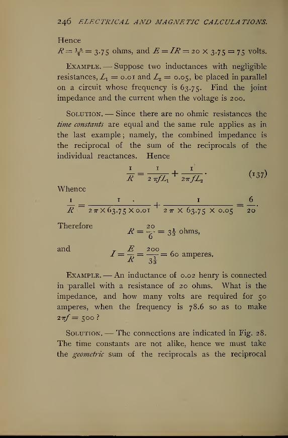
246 ELECTRICAL AND MAGNETIC CALCULATIONS.
Hence
R = J?5_ = 2.75 ohms, and E = IR = 20 X 3.75 = 75 volts.
Example.— Suppose two inductances with negligible
resistances^! = 0.0 1 and Z2= 0.05, be placed in parallel
on a circuit whose frequency is 63.75. Find the joint
impedance and the current when the voltage is 200..
Solution.— Since there are no ohmic resistances the
time constants are equal and the same rule applies as in
the last example ; namely, the combined impedance is
the reciprocal of the sum of the reciprocals of the
individual reactances. Hence
Z = ^^ + 2^7^' (I37^
Whence
1 1 1 6
R ~ 2 7T X 63.75 X °*01 2 7T X 63.75 X O.O5 " " 20
Therefore 20 , .R = — = 3J ohms,
and T E 200 r/ = — = —- = 60 amperes.
Example.— An inductance of 0.02 henry is connected
in parallel with a resistance of 20 ohms. What is the
impedance, and how many volts are required for 50
amperes, when the frequency is 78.6 so as to make
27l/= 5OO ?
Solution.— The connections are indicated in Fig. 28.
The time constants are not alike, hence we must take
the geometric sum of the reciprocals as the reciprocal
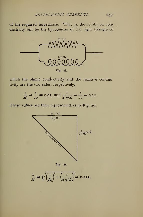
ALTERNATING CURRENTS. 247
of the required impedance. That is, the combined con-
ductivity will be the hypotenuse of the right triangle of
R=20
r^WVWWWKL=.02
sMMM^yPig. 28.
which the ohmic conductivity and the reactive conduc
tivity are the two sides, respectively.
11 , 1 1
Tr = — = 0.05, and — = — = 0.10.R^ 20 °'
2 irfL 10
These values are then represented as in Fig. 29.
Ri = 20
\ v 05
%V
Fig. ag,
27T/L
rW=-
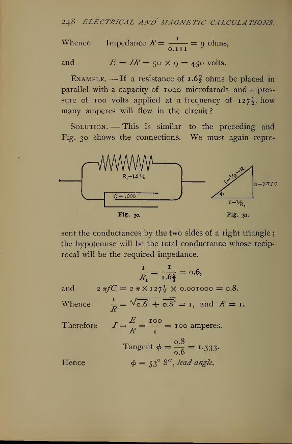
248 ELECTRICAL AND MAGNETIC CALCULATIONS.
Whence Impedance R =0.1 1.1
= 9 ohms,
and E = IR = 50 X 9 = 450 volts.
Example. — If a resistance of i.6f ohms be placed in
parallel with a capacity of 1000 microfarads and a pres-
sure of 100 volts applied at a frequency of 127^, howmany amperes will flow in the circuit ?
Solution. — This is similar to the preceding and
Fig. 30 shows the connections. We must again repre-
HWWW\AAR,-Wy,
C=1000
Fig. 30.
.8=27T/C
sent the conductances by the two sides of a right triangle;
the hypotenuse will be the total conductance whose recip-
rocal will be the required impedance.
i=^k = °-6'
and 2 7rfC = 2 7rX 127^- X 0.001000 = 0.8.
Whence
Therefore
Hence
1 = V0.62 + 0.82 = 1, and R = 1,R
E 100I = — = =100 amperes.R 1
rr, O.8Tangent <j> = —- = 1.333.
0.0
<£ = 53 8", lead angle.
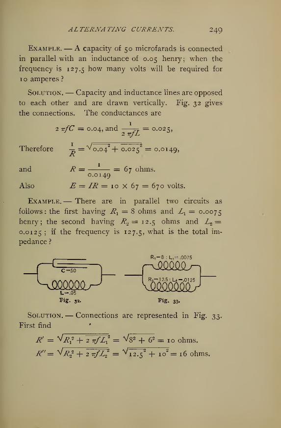
ALTERNATING CURRENTS. 249
Example.— A capacity of 50 microfarads is connected
in parallel with an inductance of 0.05 henry; when the
frequency is 127.5 how many volts will be required for
10 amperes ?
Solution.— Capacity and inductance lines are opposed
to each other and are drawn vertically. Fig. 32 gives
the connections. The conductances are
2 tt/C = 0.04, and —— = 0.025,2 TTjL
Therefore — =^o.o42 + 0.025 = 0.0149,R
and R = = 67 ohms.0.0149
Also E = IR = 10 x 67 = 670 volts.
Example.— There are in parallel two circuits as
follows: the first having Rx= 8 ohms and L
x= 0.0075
henry; the second having R2= 12.5 ohms and Z2
=0.0125 ; if the frequency is 127.5, wna-t is the total im-
pedance?
^= 8 : L,-.0075
12.5: U -\01 25
Fig. 33.
Solution.— Connections are represented in Fig. 330
First find
R' = V^2 + Y^r/%2 = Vs2 + 62 = 10 ohms.
R"= ^R22 + IrfZ? = ^7^5 2 + io
2 = 16 ohms.
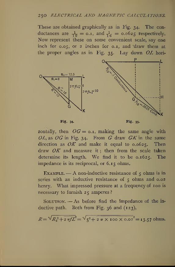
25O ELECTRICAL AND MAGNETIC CALCULATIONS.
These are obtained graphically as in Fig. 34. The con-
ductances are -X- = 0.1, and -J* = 0.0625 respectively.
Now represent these on some convenient scale, say one
inch for 0.05, or 2 inches for 0.1, and 'draw them at
the proper angles as in Fig. 35. Lay down OL hori-
R 2 =12.5
27T/Lr 10
Fig. 34. Fig. 35.
zontally, then 0(9=0.1, making the same angle with
<9Z, as OG in Fig. 34. From G draw GK in the same
direction as OK and make it equal to 0.0625. Then
draw OK and measure it ; then from the scale taken
determine its length. We find it to be 0.1625. The
impedance is its reciprocal, or 6.15 ohms.
Example.— A non-inductive resistance of 5 ohms is in
series with an inductive resistance of 5 ohms and 0.02
henry. What impressed pressure at a frequency of 100 is
necessary to furnish 2 5 amperes ?
Solution.— As before find the impedance of the in-
ductive path. Both from Fig. 36 and (123),
R= v^22+ 2 ?r/Z
2= ^5 2+ 2 7T X 100 X o.o22= 13.57 ohms.
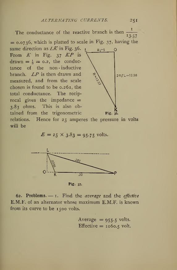
ALTERNATING CURRENTS. 251
The conductance of the reactive branch is then!3-57
27?/L= 12.56
= 0.0736, which is platted to scale in Fig. 2>h having the
same direction as LK in Fig. 36. ^ r,=5
From K in Fig. 37 KP is
drawn = \ = 0.2. the conduc-
tance of the non-inductive
branch. LP is then drawn and
measured, and from the scale
chosen is found to be 0.261, the
total conductance. The recip-
rocal gives the impedance =3.83 ohms. This is also ob-
tained from the trigonometric
relations,
will be
Fig. 36.
Hence for 25 amperes the pressure in volts
E = 25 X z&z = 95.75 volts.
O'—
^7
K .20
Fig. 37.
62. Problems.— 1. Find the average and the effective
E.M.F. of an alternator whose maximum E.M.F. is known
from its curve to be 1500 volts.
Average = 955.5 volts.
Effective = 1060.5 volt.
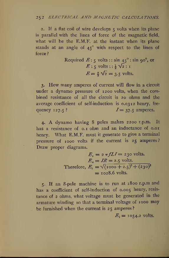
252 ELECTRICAL AND MAGNETIC CALCULATIONS.
2. If a flat coil of wire develops 5 volts when its plane
is parallel with the lines of force of the magnetic field,
what will be the E.M.F. at the instant when its plane
stands at an angle of 45 with respect to the lines of
force ?
Required E\ 5 volts : : sin 45 : sin 90 , or
E 15 volts : : \ V2 : 1
E = f V2 = 3.5 volts.
3. How many amperes of current will flow in a circuit
under a dynamo pressure of 1200 volts, when the com-
bined resistance of all the circuit is 20 ohms and the
average coefficient of self-induction is 0.0312 henry, fre-
quency 127.5? ^ == 37-S amperes.
4. A dynamo having 8 poles makes 2200 r.p.m. It
has a resistance of 0.1 ohm and an inductance of 0.01
henry. What E.M.F. must it generate to give a terminal
pressure of 1000 volts if the current is 25 amperes?
Draw proper diagrams.
Es= 2 tt/LI— 230 volts.
Ea = Zff = 2.5 volts.
Therefore, E{= V(iooo + 2.5)2 + (230)
2
= 1028.6 volts.
5. If an 8-pole machine is to run at 1800 r.p.m and
has a coefficient of self-induction of 0.005 henry, resis-
tance of 2 ohms, what voltage must be generated in the
armature winding so that a terminal voltage of 1000 may
be furnished when the current is 25 amperes?
Ei= 1054.2 volts.
ALTERNATING CURRENTS. 253
6. The pressure applied to a circuit whose resistance
was 5 ohms was 250.32 volts, the circuit carrying 50 am-
peres ; what was the E.M.F. of self-induction ? Also if
the frequency was 63.75, what was the coefficient of
inductance? Es= 12.65 volts.
L = 0.00063 henry.
7. How many amperes will pass through a circuit
under 100.7 volts applied at a frequency of 63.75, wnen
the resistance is 10 ohms and inductance 0.0 1 henry?
What are the ohmic and inductive drops?
/ = 10 amperes.
Ea= 100 yolts.
E$= 40 volts.
8. What resistance may be added in a circuit whose
inductive drop at 100 amperes is 300 volts, when 500
volts is the impressed pressure ? What is the active pres-
sure and impedance ? Rx= 4 ohms.
Ea = 400 volts.
R = 5 ohms.
9. What E.M.F. at a frequency of 125 must be applied
to a condenser circuit whose capacity is 100 microfarads,
so that 1 o amperes of current will flow ?
E{= 127.4 volts.
10. What capacity must be put into an alternating cur-
rent circuit of negligible resistance, so that 50 amperes
may be obtained at a pressure of 500 volts and frequency
of 1 27J? C, = i25 microfarads.
1 1
.
What is the capacity reactance in problem 10?
R = 0.1 ohm.
2 54 ELECTRICAL AND MAGNETIC CALCULATIONS.
12. What is the impedance of a circuit which contains
an ohmic resistance of 40 ohms in series with a capacity
resistance of 30 ohms ?
R = V302 + 402 = 50 ohms.
13. If 10 amperes are required through the circuit in
problem 12, how many volts of E.M.F. must be impressed
upon it ? Find the ohmic and capacity drops.
Ei = 10 X 50 = 500 volts.
Ec = 10 X 30 = 300 volts.
Ea = 10 x 40 = 400 volts.
14. A dynamo supplies 25 amperes to a circuit con-
sisting of 10 ohms in series with a capacity of 100 micro-
farads at a frequency of 63.75. What is the terminal
voltage of the dynamo, and what is the drop in each por-
tion of the circuit? E{
• = 673 volts.
Ea = 250 volts.
Ec = 625 volts.
15. When a capacity of 10 microfarads is in series
with a resistance of 10 ohms, and an E.M.F. of 638 volts
at a frequency of 100 is impressed upon the circuit, how
many amperes will pass through it, and what will be the
drop of potential on each portion of the circuit ?
1=4 amperes.
Ea= 40 volts.
Ec = 636.8 volts.
16. What is the time constant of a circuit whose resist-
ance is 10 ohms and whose inductance is 0.05 henry?
L o.oq/ = — = =0.005 sec#K 10
ALTERNATING CURRENTS. 255
17. What is the coefficient of self-induction of a circuit
whose time constant is 0.0 1 second and whose resistance
is 5 ohms. L = 0.05 henry.
18. An alternating current circuit is carrying 5 am-
peres under an impressed pressure of 50 volts at a
frequency of 1271. If its resistance is 6 ohms, wrhat is
its time constant ?
/ = — = 0.00 1 6t seconds.R 3
19. What current will flow through a circuit having a
negligible resistance, an inductance of 0.05 henry, and
a capacity of 1 microfarad in series, when a pressure of
500 volts is applied at a frequency of 100 ? Draw
diagram. /= 0.32 ampere.
20. What capacity must be put in series with an in-
ductance of 0.02 henry when the • frequency is 63.75 so
that the impedance shall be zero ?
(7=312 microfarads.
21. How many amperes will flow under the conditions
given in problem 20, if a resistance of 50 ohms be added
in series and 1000 volts E.M.F. be applied?
I = 20 amperes.
22. What is the coefficient of self-induction of a coil of
500 turns through which the magnetism is changing at
the rate of io5 lines of force per second ?
L = nlV-r- io9 = 0.05 henry.
23. How many lines of force are produced in a coil
having 10 turns per centimeter of its length and a cross
256 ELECTRICAL AND MAGNETIC CALCULATIONS.
section of 10 square centimeters when it carries 10 am-
peres of current, no iron being in its vicinity ?
n _ \TrriAI r ..
JV= = 1256 lines.10 °
24. How would the number of lines be affected if an
iron core were introduced into the coil, and its permeability-
be given as //, = 500 ?
4 TTfl AIu. - _JV= =628,000 lines.
10
25. If the total length of the coil in problem 24 is 50
centimeters, what E.M.F. of self-induction is set up under
the conditions named ?
E = ± g-t- = 3.14 volt.ioy
26. What is the inductance under the conditions
named in problem 25 ?
L == '-= = in absolute value.
E ATrnn'Au,L= -j = —^— = 0.314 henry,
in practical units.
27. If a voltage of 1040 at a frequency of 125 be ap-
plied to a circuit consisting of a resistance of 10 ohms, an
inductance of 0.05 henry, and a capacity of 100 micro-
farads, all in series, how many amperes of current will
flow in the circuit, and what is the impedance ? Also the
drop over each portion of the circuit ?
/ = 36.7 amperes.
R = 28.3 ohms.
Ea= 367 volts,
Ec = 466 volts.
ALTERNATING CURRENTS. 2 $7
28. There are in parallel two inductances, I^= 0.0002
henry, Z2= 0.0004 henry. The frequency is 100. What
is the impedance, and how much current will flow under
an impressed pressure of 8.37 volts ?
R = 0.0837 onm -
/ = 100 amperes.
29. An inductance Z= o.o5 henry is placed in parallel
with a non-inductive resistance of 10 ohms. When a volt-
age of 177 is applied to the circuit at a frequency of 60,
how many amperes will flow ? R = 8.85 ohms.
I = 20 amperes.
30. Let an inductance of 0.0 1 henry be placed in
parallel with a capacity of 50 microfarads; what E.M.F.
at a frequency of 127^- must be applied to the circuit to
give 10 amperes of current ? How many amperes will
pass in each branch ? R = 11.77 ohms.
E = 1 1 7.7 volts.
Is= 14.71 amperes.
Ic =4.71 amperes.
31. A coil of wire has an ohmic resistance of 10 ohms
and an inductance of 0.0156 henry. What is the im-
pedance when the frequency is 127J?R = 16 ohms.
32. A capacity circuit has a capacity of 156^ micro-
farads in series with a resistance of 10 ohms. Find the
impedance at a frequency of 127 J. R = 12.8 ohms.
^^. Place the circuit of problem 31 in parallel with that
of problem 32 and find the joint impedance. Find the
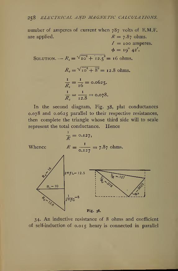
258 ELECTRICAL AND MAGNETIC CALCULATIONS.
number of amperes of current when 787 volts of E.M.F.
are applied. R = 7.87 ohms.
/ = 100 amperes.
<£ = 19 42'.
Solution.— Rs= ^io
2 + i2»52 = 16 ohms.
Rc = ^io2 + 8
2 = 12.8 ohms.
i = ie = °-o62S -
±. = -i- = o.o7 8.
In the second diagram, Fig. 38, plat conductances
0.078 and 0.0625 Parallel to their respective resistances,
then complete the triangle whose third side will to scale
represent the total conductance. Hence
Whence
RR =
= 0.127,
1
0.127= 7.87 ohms.
27T/L- 12.5
Fig. 38.
34. An inductive resistance of 8 ohms and coefficient
of self-induction of 0.015 henry is connected in parallel
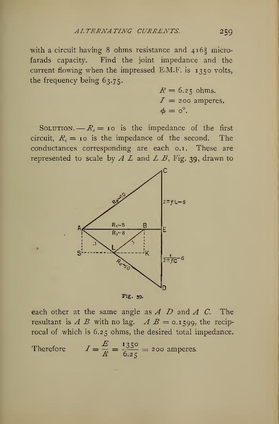
ALTERNATING CURRENTS. 259
with a circuit having 8 ohms resistance and 4i6f micro-
farads capacity. Find the joint impedance and the
current flowing when the impressed E.M.F. is 1350 volts,
the frequency being 63.75.
R = 6.25 ohms.
7 = 200 amperes.
<t>= o°.
Solution.— ^, = 10 is the impedance of the first
circuit, Rc = 10 is the impedance of the second. The
conductances corresponding are each 0.1. These are
represented to scale by A L and L B, Fig. 39, drawn to
C
2TT/L--6
r=62 7T/C
Fig. 39.
each other at the same angle as A D and A C. The
resultant is A B with no lag. A B = 0.1599, tne recip-
rocal of which is 6.25 ohms, the desired total impedance.
ThereforeE 1350
R 6.25200 amperes,
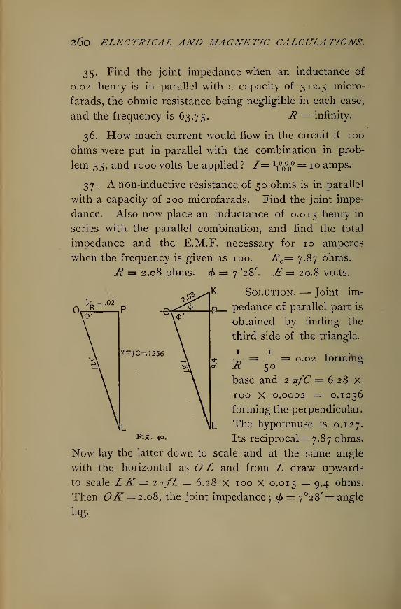
26o ELECTRICAL AND MAGNETIC CALCULATIONS.
35. Find the joint impedance when an inductance of
0.02 henry is in parallel with a capacity of 312.5 micro-
farads, the ohmic resistance being negligible in each case,
and the frequency is 63.75. ' i? = infinity.
36. How much current would flow in the circuit if 100
ohms were put in parallel with the combination in prob-
lem 35, and 1000 volts be applied ? f=*ffip-= 10 amps.
37. A non-inductive resistance of 50 ohms is in parallel
with a capacity of 200 microfarads. Find the joint impe-
dance. Also now place an inductance of 0.015 henry in
series with the parallel combination, and find the total
impedance and the E.M.F. necessary for 10 amperes
when the frequency is given as 100. Rc= 7.87 ohms.
jR = 2.08 ohms. <£ = 7°28 /. E = 20.8 volts.
Solution. — Joint im-
pedance of parallel part is
obtained by finding the
third side of the triangle.
1
Rbase and 2 ir/C = 6.28 X100 x 0.0002 = 0.1256
forming the perpendicular.
The hypotenuse is 0.127.
¥i^- 40. Its reciprocal= 7.87 ohms.
Now lay the latter down to scale and at the same angle
with the horizontal as O L and from L draw upwards
to scale LK'= 2-nfL = 6.28 x 100 X 0.015 = 9.4 ohms.
Then OK = 2.08, the joint impedance ; <j> = 7°28'= angle
lag.
2TTfc=A256 = — = 0.02 forming
ALTERNATING CURRENT DISTRIBUTION 26 1
XIII.
ALTERNATING CURRENT DISTRIBUTION.
63. Alternating Current Circuits.— It has already been
shown that there are several causes making it inaccurate
to apply Ohm's law strictly to calculations in alternating
currents. However, where the transformer secondaries
are loaded with incandescent lamps, the effect of induc-
tance becomes negligibly small, so that the inaccuracies
will not be very great for moderate lengths of circuits.
Practically the ratio of transformation of transformers
is the ratio of the primary turns to the secondary turns, or
the ratio of the secondary current to the primary current.
The ratio of transformation of transformers used for in-
candescent lighting on single-phase circuits is usually 20 or
10. In the monocyclic * system ratios of 9 and 4 are often
used. In long distance polyphase transmission various
ratios are employed, particularly in the large sizes of
transformers. In a town having a population of 5000 to
10,000, the lighting plant being centrally located, the
primary E.M.F. will be, perhaps, 2000 to 2200 volts, and
the secondary 100 to no volts, the ratio being 20. Where
the primary mains are quite short, possibly the primary
E.M.F. would be 1000 volts, and the ratio of transformation
10. In the Niagara-Buffalo line, the power is brought to
the city limits at 22,000 volts, then transformed to 11,000,
the ratio of transformation being in this case but 2.
* The monocyclic system is no longer a commercial system.
262 ELECTRICAL AND MAGNETIC CALCULATIONS.
The efficiency of the larger sizes of transformers is from
95 per cent to 99 per cent, and the core losses and the
copper losses are about equal. To obtain a given energy
in the secondary, the primary current will be increased by
the amount of the core loss per cent, while the primary
voltage will be increased by the per cent of copper loss.
Example. — When the secondary of a transformer is
wound for 52 volts, and the ratio of transformation is 20,
what is the primary current for a 1000 watt transformer?
Solution.— Secondary current
I2 = 1000 -*- 50 = 20 amperes.
This will furnish 20 lights, 16 c.p.
Primary voltage = 52 X 20 = 1040 volts.
Primary current 7j= 20 -1- 20 = 1 ampere.
Therefore,
Watts in primary for no loss = 1040 X 1 = 1040 watts.
If the loss be 5 per cent, then
Watts in primary coil = 1040 -7- 0.95 = 1095.
Suppose copper and iron losses equal, each being 2\ per
cent. Then the primary current is
Ix= i-r- 0.975 = 1.025 amperes.
Primary E.M.F.
Ex= 1040 -7- 0.975 = 1066.66 volts.
Otherwise, Ex= 1095 -f- 1.025 = io^7 v°lts.
Strictly, the ratio of transformation here is 20 -f- 1.025 =19.4 instead of 20. Hence the transformer * losses have
the effect of reducing the ratio of transformation.
* This refers to the iron losses.
ALTERNATING CURRENT DISTRIBUTION 263
Example.— What is the maximum per cent drop in the
secondaries in the last example if 50 volt, 1 ampere
lamps are to be used ? What size of wire will be used, and
what must be the size of the primary mains, neglecting
drop due to inductance, if an ohmic loss of 10 per cent be
allowed, and the distance be \ mile ?
Solution.— Secondary loss = 2 volts -2-52 =3.8 per
cent. Assume the distance to the lamps to be 100 feet.
Then the line resistance per 1000 feet is
R9 = (2 -r- 20) X = o.q ohm, which is No. 7 A.W.G.2 v J 200 ° '
For the primary, Ix = 1.025 amperes;
E (drop) = — 1067 = 110 volts.v
' 0.90
Hence Rx= 119 -*- 1.025 = 116 ohms for 5280 feet.
Making per 1000 feet, Rx= 116 -f- 5.28 = 22 ohms,
or No. 23 wire. This loss, of course, is excessive.
Machine voltage = 1067 -*- 0.90 = 1186 volts.
The table No. 10 will give the impedance, the ohmic re-
sistance and the inductive resistance in ohms per mile of
those sizes in which there will be an appreciable effect at
the given distances of the wires apart. These values are
given for frequencies of 60 and 125 per second. The
column headed Rx means ohms resistance per mile, Rsis
the inductive resistance in ohms per mile, and R is the
impedance or resultant resistance in ohms per mile. It
will be observed that the values in the columns headed Rare obtained from
R = \lR? + 4 tt2/2 L2 = \IR* + R9\
264 ELECTRICAL AND MAGNETIC CALCULATIONS.
Thus for No. o at 12 inches apart,
R = ^0.519* + ^552= 0.756.
It is safer to add 15% to the tabular inductive resis-
tances to compensate for distortion from the sine wave.
Example. — By means of the table determine the
E.M.F. necessary to apply to a circuit \\ miles long to
carry 10 amperes, when No. 1 wire is used 12 inches
apart, and the frequency is 60.
Solution.—Rx of No. 1 for 3 miles = 0.655 x 3 = x -965 ohms.
Rs of No. 1, 3 miles = 0.565 X 3 = 1.695 ohms.
Impedance R = 0.865 X 3 = 2.595 ohms,
or R = V 1.695s + 1.965
2 = 2.595 ohms.
Since E = IR, 1= 10, and R = 2.595,
£=ioX 2 -S9S = 2 5«95 volts line drop.
If there were no self-induction E would be
1.965 X 10 =19.65 volts drop.
Therefore 25.95 — 19-65 = 6.30 volts necessary for
inductive drop on line.
At 125 cycles per second this would be
E = 1.349 X 3 X 10 = 40.47 volts total drop.
Inductive drop is 40.47 — 19.65 = 20.82 volts. If the
load is non-inductive, as incandescent lamps, the gener-
ator must furnish 20.82 volts more on account of line
self-induction.
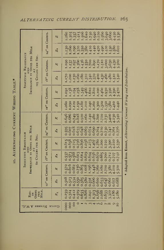
ALTERNATING CURRENT DISTRIBUTION 265
wuz<Hen>*
enW
H>HU
az
HPh
73
S
«ZMUZ<aHcu
S
Uwm
w
< aau>U
COPi
"S
UO
*O^or^^ooOO OOOOOOOO "T-" O "-" iot}- no ^O *-o coN fOnTJ- LOvq nonn 1000 ^f ^M M M 1-4 M M M M N N CO CO rf LT)
£OOOOOOOOOOOOOOfOO CA M LOOO i-1 't N ON IO00 N
W>*VG<u
Uc
00
^Or^t^OvOOOOOOOOOOOn co ONO fO'-OO O N n o fOfOOci N N CO "<T *0 t^OO m 10OO "T ^9M M Ml M M H H M* ei n CO CO "^ 10
c<
OOOOOOOOOOOOOOt^ O COO 00 m TfNO COO 00 Mt t^-
hh N N N N r9 ror? TtTr T
f,1" LOlJ
?
801Mc0)
c
*N 00 TJ-00 ONO OOOOOOOOC\ coOmo "3*0 i-h n OO n(>ONNm m n n ^vq 00 « tj- on «o co >^-
hh* 1^* hh" m m i-3 M M N N N CO ^ vo
•OOOOOOOOOOOOOOO ON N LO00 •-" TfO O N ^nOO i-i ^*
q O hi m m n n N co co co co rt rt-
Huz<HnSoH
a>HU
QZ
AND
Impedance
in
Ohms
per
Mile
at
60
Cycles
per
Sec.
S«->
SOe
&$
O O OnCO OOOOOOOOOOtJ-GO ^" 1-1 N O ^"00 O hi rO O CO rj-O O i>.oq on q n tj-oo
#r>. r>. tj- n co
0' 0" d h m m h n n n ^ »o
£lo r^oo cooo co-^O Tf O O n m\0On O "h ro TfO r^ ON O n co TfO r^10O OOOOOOO r^t^t^r^r^r^6666666666 6 6 6 6
C/3
0)
suc
06
*looO *-r>\D OX fONO O OO O ON-t tin OnOnconOOO O N ONN COO O !>• t->.0q O N tJ-NN NtON CO
d d w « h m n n n 4 ^
«0
I^ COOO CO Tf ON rfO O »0 O N N M!-Ot^OO O t-i N Tj-^Or^OO O m N t*o 10 voo OOOOOO r^r^r^r^d d 0' 0* 6 0' 0* 6 6 6 6
00
\s-4->
c0)
Us
^O O N O LO00 OOOOOOOOO^ ^ 9S ^O O ON TJ-VO OOmOO h NlOO O tv.00 OHrtNHNrONnd O O d d •-' m h m fi n ro 4 ^
£^? Js?^5L^\S M ^ ^^N t^OOO N CO LOO 00 ON O N co rj-O r^ooIO l^ IO IO IT) IO l-OOOOOOOO66666666666666
H 2
73 Ei
j
j
HON^N Os iOO t-H roO 00 co O O OlONwwu-iNTfH-c LOOO CO N 00 00N
. *? 'I" ^^ °°. 9 ^^ O O CO 11 Nooodddi-Ii-J^NNcoTtLo
O'AY'V *aa*ici$[ a jDHVOOOOO^incOtJ- 10O t^00 ON O88°
Pia-a<
266 ELECTRICAL AND MAGNETIC CALCULATIONS.
Let the load be 20 groups of no volt incandescent
lamps, 5 in series in each group. This will require
110X5=550 volts at the lamp terminals. The resis-
c X 220tance of the load is therefore = c; c ohms. This
20 °°
is in series with the line resistance and inductance.
Take the frequency at 60, then neglecting dynamo resis-
tance and inductance, the impedance of the circuit
will be
R = Vi.96 5 + 552 + 1.695
2 = 57 ohms.
The total impressed E.M.F. must be
E = IR = 10 X 57 = 570 volts.
Hence the line drop due to all causes is 570 — 550 =20 volts, while the ohmic drop alone is 19.65 volts.
Therefore it is plain that for non-inductive loads and very
small machine inductance, the line self-induction is not
a very disturbing factor.
Example.— Assume the machine resistance to be
0.4 ohm and the coefficient of self-induction L = 0.02
henry, speed so as to make /= 60 cycles, supplying
10 amperes as the above load. Find the total impedance
and the E.M.F. in the armature conductors.
Solution.— Total reactance is ^=1.695 -f- 27r X 60 X0.02 = 9.231 ohms. The total impedance is
R = ^56.9652 + 9.231
2 = 58 ohms.
This is not appreciably different from that found above
because the resistance is quite large in proportion to the
ALTERNATING CURRENT DISTRIBUTION. 267
reactance ; that is, the time constant is very small. Hence
the armature self-induction has not seriously disturbed
the regulation.
Example. — It is required to determine the size of
wire at 12 inches apart for the circuit and load given
above so that the total drop shall not exceed 25 volts.
Solution. — E.M.F. at load =550 volts.
Impressed E.M.F. = 550 + 25 = 575 volts.
Armature reactance Rs= 7.536 ohms = 27r x 60 x 0.02.
Let the line resistance be Rv then the impedance
R = Ytf^ + x + 7 .53 62 = -Vo
5- = 57-5 ohms.
Solving for Rxand neglecting terms containing x, since
the line reactance is relatively small, we get
_RX = 57.4 ohms.
Therefore the line resistance per mile is
57 '4 ""55 = 0.823 ohm.
According to the table this corresponds to No. 2 wire.
Taking into account the transformer inductance and
the transformer and lamp losses under ordinary condi-
tions, when the transformers cannot be counted on as
more than three-fourths loaded, it may be assumed with-
out great error that the self-induction will cause a lag of
8° or less, making the power factor 0.99 and the induc-
tance factor 0.14. In case of very light loads on trans-
former secondaries, the figures may become in practice
0.98 for the power factor and 0.19 for the inductance
factor, and u° for the angle of lag.
268 ELECTRICAL AND MAGNETIC CALCULATIONS.
Where transformers supply motor loads the power
factor would probably run down to 75% or 80%. How-ever, if both transformers and motors could be fully loaded
— a rare thing in practice— the power factor with mod-
ern appliances might go over 90%.
Example. — Taking a circuit whose power factor is
99%) what is the proportion of impressed E.M.F. to
active E.M.F. in the circuit?
Solution.—tanrp wnn 4- ta too
approximately.E
{Impedance V992 + 14
2100
Ea Resistance 99 99
In other words, when the E.M.F. necessary to force the
desired current through the given resistance would be
990 volts, the impressed voltage must be 1000, 10 volts
being required to overcome the inductive resistance.
Example.— Taking 0.80 as an average power factor
for motor loads, the inductance factor will be about 0.595
and the lag 36I- . Find the impedance factor and ratio
of impressed volts to active E.M.F.
Solution.—Impedance = ^o.8o
2 + 0.5952 = 0.997 ohm.
E{ 0.997
E„ 0.80= 1.246.
In words, if 1000 volts would send the desired current
through the given resistance, 1246 volts must be im-
pressed upon the circuit; 1246 — 1000 = 246 volts extra
are required, due to self-induction.
ALTERNATING CURRENT DISTRIBUTION. 269
The following examples have been taken from Emmet's" Alternating Current Wiring and Distribution." Theywill serve to illustrate the type of solution which may be
applied to problems under the present section. In such
problems as these that follow consider the ratio of trans-
formation one, and use the primary voltage and current
on both sides of the transformer.
Example.— Assume 500 incandescent lamps of 57.5
watts each on secondaries of transformers of different
sizes, half loaded, on the average. The mains to the
transformers consist of No. 2 B. & S. wire 2 miles long
and 18 inches apart. The frequency is 125. The lamp
voltage is to be 100 and the ratio of transformation is 10.
Determine the voltage required at the generator and the
ohmic drop on the line.
Solution.—Lamp active volts = 1000 ; lamp current 28.75.
Secondary ohmic drop 3% = 30 volts; inductive drop
3% = 30 volts.
Transformers, ohmic drop 1% = 10 volts ; inductive
drop i2^% = 130 volts.
Core loss 5% of 28.75 = x -44 amperes. Total /=30.19.
Line current = 30.19 amperes. Ohmic drop= (o.826 X
4) X 30.19 = 99 volts; inductive drop (1.31 X 4) X
30.19 + 15% = 182 volts.
Now add active volts and ohmic drops for total active
volts.
270 ELECTRICAL AND MAGNETIC CALCULATIONS.
Whence Ea = iooo + 30 + 10 + 99 = 1139 v°lts.
Also add inductive drops giving
Es= 30 + 130 + 182 = 342 volts.
Impressed pressure
Ei= V11392 + 342
2 = 1 188 volts.
The line loss due to ohmic resistance = 99 volts.
Total line loss = 30 + 10 + 99 = 139 volts
;
or II 39 — 1000 = 139.
Example.— From a water power it is desired to run a
circuit 14 miles to supply a compact district with 500
K.W. in incandescent lamps, the current being distributed
in the town on the three-wire, low-tension system from a
transformer substation. Station pressure is 130 volts at
full load, lamps 120 volts. The maximum potential is
about 10,000 volts. For the substation 40 K.W. trans-
formers are used in seven pairs, ratio 10 to 1, primaries
connected two in series, and their secondaries connected
for the three-wire system. The frequency is 60. The
line is No. 00 B. & S. If we may assume a power
factor of 0.99, and an inductance factor of 0.14, what will
be the values corresponding to those obtained in previous
example ?
Solution.— First reducing secondary circuits to main
line conditions, we obtain 9100 volts and 59.7 amperes.
By use of the table we obtain the line resistance 0.412
ohm per mile, inductive resistance at 12 inches apart
0.534 ohm per mile ; and adding 15% this becomes 0.614
ohm per mile.
ALTERNATING CURRENT DISTRIBUTION. 2 J I
On secondaries,
0.99 X 9100 = 9000 active volts.
Also 0.14 X 9100 = 1270 inductive volts.
/== 59.7 amperes.
Reducing transformers,
Ohmic drop i°/ of 91 00 = 91 volts.
Inductive drop 6°/ of 9100 = 546 volts.
Core loss, say 3% of 59.7 = 1.78 amperes.
Main line,
Ohmic drop 0.412 X 28 X (59.7 + 1.78) = 7 10 volts.
Inductive drop
0.614 X 28 X (59.7 + 1.78) = 1060 volts.
Total active volts
Ea = 9000 + 91 + 710 = 9801.
Total inductive drop
Es= 1270 + 546 + 1060 = 2876 volts.
Therefore the voltage to be supplied at the secondaries
of the step up transformers is
2 2
9801 +2876 = 10,200 volts.
The current supplied by step up transformers is
/ = 59.7 + 1.78 = 61.5 amperes.
Ohmic drop i°/ of 10,200 = 102 volts.
Inductive drop 6°f of 10,200 = 612 volts.
Core loss $°/o of 61.5 = 1.85 amperes.
Therefore the active voltage supplied by the gen*
erator is Ea — 9801 + 102 = 9903 volts,
And Es= 2876 + 612 = 3488 volts.
272 ELECTRICAL AND MAGNETIC CALCULATIONS.
Therefore E{=z^/ggo^
2 + 3488s = 10,500 volts.
And / = 61.5 + 1.85 = 63.4 amperes.
Hence the generator delivers 10,500 X 63.4 = 665,700
volt-amperes, and 10,500 X 59.7 = 626.8 K.W.
The power delivered at the transformer station is
\%% X 130 =541 K.W., and the efficiency of the plant
from generator to step-down secondaries is 541-5-627
= 86%.
Sixteen of the 40 K.W. transformers connected two in
series to the generator, and two in series to the line are
used as step-up transformers, receiving 1050 volts and
delivering 10,500 volts.
The generator capacity is 665 K.W., and allowing 92%efficiency, there will be required in water power 665 -r-
0.92 = 685 K.W. Total efficiency is then 73%.
64. Formulae and Tables for Alternating Current Wir-
ing. — For most practical cases the following formulae
based on Ohm's law will be very convenient and suffi-
ciently accurate for the calculation of transmission cir-
cuits. The constants which are introduced in the formulae
have the values under the different conditions given in
the proper tables ; these are taken from the publications
of the General Electric Company.
Symbols. — / = total line current.
E = E.M.F. at customer's end of circuit.
W— Watts delivered to the customer.
oJ = Per cent of W loss in line.
D = Distance of transmission.
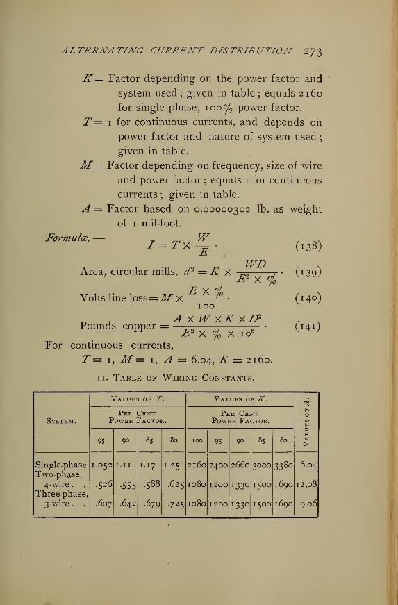
ALTERNATING CURRENT DISTRIBUTION 273
K= Factor depending on the power factor and
system used;given in table ; equals 2160
for single phase, 100% power factor.
T= 1 for continuous currents, and depends on
power factor and nature of system used
;
given in table.
Jlf= Factor depending on frequency, size of wire
and power factor ; equals 1 for continuous
currents;given in table.
A = Factor based on 0.00000302 lb. as weight
of 1 mil-foot.
Formula.— _ WI=TX-E-
WDArea, circular mills, d2 = K X
^X %£2 x %
Volts line loss=M X100
A X WxKxD2
Pounds copper = £2 x % x io (
For continuous currents,
T= 1, M— 1, A = 6.04, K = 2160.
11. Table of Wiring Constants.
(138)
(!39)
(140)
(i4i)
Values of T. Values of K.
Per Cent Per CentSystem. Power Factor. Power Factor. 73
w&1-1
<>95 90 85 80 100 95 90 85 80
338oSingle-phase I.052 I. II 1. 17 I.25 2160 2400 2660 3000 6.04
Two-phase,4 -wire . . .526 •555 .588 .625 1080 1200 I330 1500 1690 12.08
Three-phase,
3 -wire . . .607 .642 .679 •725 1080 1200 l 33° 1500 1690 906
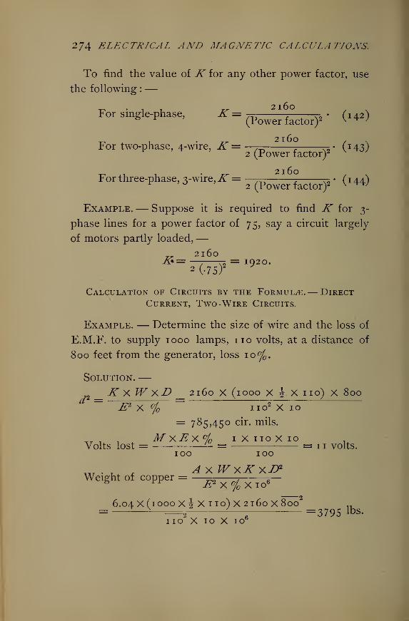
274 ELECTRICAL AND MAGNETIC CALCULATIONS.
To find the value of K for any other power factor, use
the following :—
For single-phase, K = — , , N2• (142)
(Power factor)2 v * '
-r, 1 • 2160 , NFor two-phase, 4-wire, K = —7=- - ^- (143)r
2 (Power factor)2 v ^OJ
For three-phase, 3-wire,K = —- - ^= • (1 44)^'
°2 (Power factor)2 v w
Example.— Suppose it is required to find K for 3-
phase lines for a power factor of 75, say a circuit largely
of motors partly loaded,—2160
a»= —.—V2= 1920.
2 (-7S)2
Calculation of Circuits by the Formula.— DirectCurrent, Two -Wire Circuits.
Example. — Determine the size of wire and the loss of
E.M.F. to supply 1000 lamps, no volts, at a distance of
800 feet from the generator, loss 10%.
Solution.—__ K X W XD _ 2160 X (1000 x|.Xiio)x 800"" £2 X % no2 X 10
= 785,450 cir. mils.
TTU . , MxEx°/ 1X110X10Volts lost = '— = = 11 volts.
100 100
Weight of copper = ———-, ^
—
8 rr £2 X%X io6
6.04 X (1000 XiXno)X2i6o X800 „=— V
2
J—m =3795 lbs.
no X10X10'
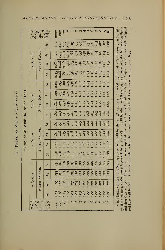
ALTERNATING CURRENT DISTRIBUTION. 2?$
SI
Hz<cc
Z
uoz
w
pq
<
H(4
wP* _)
<! u>
CO
w UX ou \Dz
O AY "V *°
S 7g -g 4HHa O O Oo oo
t^CO On o
O't NiONtsNrOM hh
i-CMOM O N iO tJ- ro N « o O OC-)NC1N^i-hi-i»-'«-''-'i-(>-ii-h>-i
Tt-NO rooo o <o o o -•
cm 1% -t h oo *> ^9 T °? c*
T On Tf Oq o q
Hs
\D 00 CO vO ^OOvO ^NO T": 9 9
CMCMCMl-HHH>-IH-l-H>-HI-IHHI-|l-IM
IO00 VO i-cVO ioianmvOfOQOO N^l^fOM CM "•
Os lovO CnO vO NO ^tOO On\Q t}- co cm « ~ O O
O O O Oo o o o
ONNOO ^t ^OO - VO CM
O r^O Tf ro ci - i-i O Oo o o oO O O o
aTt-O N OO rorsWCO rf00 vO "-^ ^ ^ ^ ^ ~' O O
cm o o oo o o o
N OI-h rt-00 ^--00^vOTfrorOCNjH-M.-iOO
ro cm O OO O O O
r>» w r^\0 r^ O ^o O O O\OiorONi-<>-iOOOO O O O OO O O O
hh oo lovo oo n Nno ovD^frOWi-ihHOOOO o o o oo o o o
N N00O ^ OHH HH O O O O
O O o oO O O O
M O ^On*-n tj- cm i-h ~ ~ O O O O
^ O O OO O O O
rf tj-vO OnrOM m o
m o o o o oo o o o o o
o o o oo o o o
ro Tj-vo o i-O CM o o o c o o o o00
CO cm W w 9 9 q q q q q q q q
On cm vO M n ^ Cl o o o o oCM CM M 9 9 q q q q q q q q
fOOO ^f OCM l-H l-H (-1
NiOfON O Oo o o o o o
o o o oo o o o
O A\ *V *°s # *a '*aa
o o o oo o oo oo
M rOTf tovo r^.00 On O
J5 &*"3 ^
CJ
II
T3 >
rt -^
S o
tuc rt
^H CO
O J
«3 SR
IT)
to u
a s
o o
» g
re
oo ^
& °
& o
•o .2
3
* o
I*
P O
ft >ft ^3 2
§2
„ c
CO
S o
^6
10 i—
•
<-e is
T3 T3
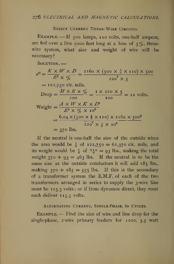
276 ELECTRICAL AND MAGNETIC CALCULATIONS.
Direct Current Three-Wire Circuits.
Example.— If 500 lamps, no volts, one-half ampere,
are fed over a line 1000 feet long at a loss of 5%, three-
wire system, what size and weight of wire will be
necessary?
Solution.—„_ KxWxD _ 2160 X (500 X \ X no) X 500
~~ £* X %= ~ Sx S
= 122,750 cir. mils.
_ MxE x % 1 X 220 x sDrop = '- = 2 = 1 ! volts.
Weight =
100 too
A XWXK XD2
& X % X 106
_ 6.04 X (500 X i X no) X 2160 X 5002
2202
x s x io6
= 370 lbs.
If the neutral is one-half the size of the outside wires
the area would be J of 122,750 = 61,370 cir. mils, and
its weight would be ^ of ^|^- = 93 lbs., making the total
weight 370 + 93 = 463 lbs. If the neutral is to be the
same size as the outside conductors it will add 185 lbs.,
making 370+ 185 =555 lbs. If this is the secondary
of a transformer system the E.M.F. of each of the two
transformers arranged in series to supply the 3-wire line
must be 115.5 volts ; or if from dynamos direct, they must
each deliver 115.5 volts.
Alternating Current, Single-Phase, 60 Cycles.
Example.— Find the size of wire and line drop for the
single-phase, 2-wire primary feeders for 1200, 3.5 watt
ALTERNATING CURRENT DISTRIBUTION, 277
no volt lamps, transformers 20 to 1. From generator to
transformers 2400- feet. Transformer drop 3%, and in
secondary wiring 2%, primary line loss 5% of delivered
watts; transformer efficiency 97%.
Solution.—Power at lamps = 1200 x (3.5 X 16) = 67,200 watts.
-r-» r . 67,200Power at transformer primary = — = 70,690 watts.
E.M.F. at transformer primary
= (110 + 2% of no) X 1.03 X 20 = 2311 volts.
Cross section,
_iTx W X D _ 2400 x 70,690 x 2400"" & X % ~~~ 2311 2 x s
= 15,250 cir. mils.
This assumes power factor =95, making K = 2400.
The nearest size is No. 8 = 16,500 cir. mils.
Loss °/ on primary mains, using No. 8, is
. Ky.Wy.D_ 2400 x 70,690 x 2400_
'° " & X d2 " 2311 2 X 16,500= 4
, MyEyo/o 1.02x2311x4.62Line drop = — =
100 100
= 109 volts.
Generator E.M.F. = 2311 + 109 = 2420 volts.
Current in primary circuit is
_ T y W 1.052 x 70,830I= —— = — — = 32.2 amperes.
Single-Phase, 125 Cycles.
Example.— Solve the above problem for a 125 cycle
circuit.
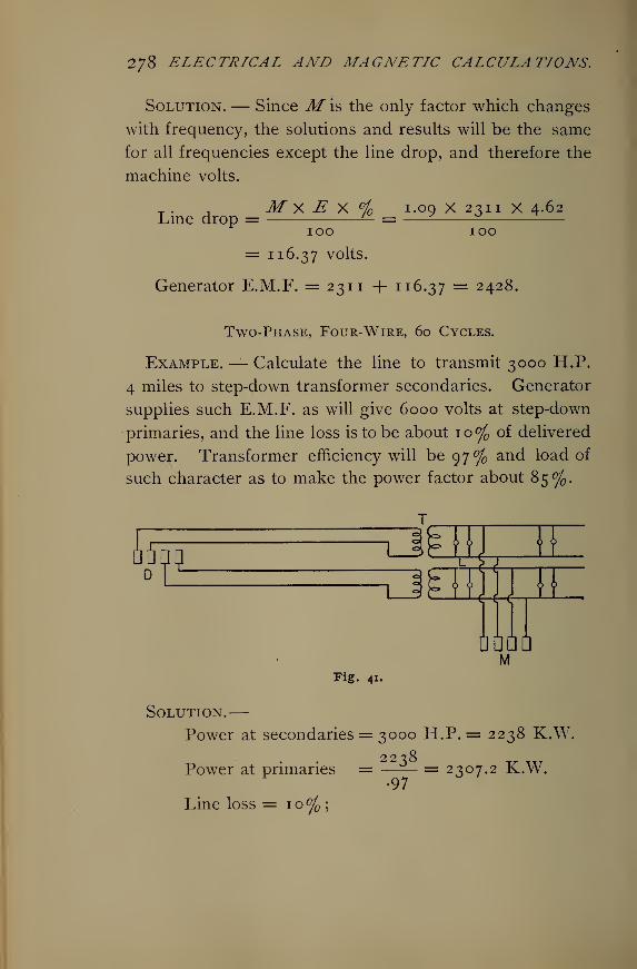
278 ELECTRICAL AND MAGNETIC CALCULATIONS.
Solution.— Since M is the only factor which changes
with frequency, the solutions and results will be the same
for all frequencies except the line drop, and therefore the
machine volts.
T . , M X E X °) i-°9 X 2311 X 4-62Line drop = — = z
100 100
= 116.37 volts.
Generator E.M.F. = 231 1 -f 116.37 = 2 42 ^.
Two-Phase, Four-Wire, 60 Cycles.
Example.— Calculate the line to transmit 3000 H.P.
4 miles to step-down transformer secondaries. Generator
supplies such E.M.F. as will give 6000 volts at step-down
primaries, and the line loss is to be about 10% of delivered
power. Transformer efficiency will be 97% and load of
such character as to make the power factor about 85%.
k11
nMii w
oamrnuaaa
MFig. 41.
Solution.—Power at secondaries = 3000 H.P. = 2238 K.W.
2238Power at primaries =
Line loss =10%;•97
= 2307.2 K.W.
ALTERNATING CURRENT DISTRIBUTION 279
Hence
_Kv.Wy.D_ 1500 x 2,307,200 x (4 x 5280)" E2 X % 6W x io~
= 203,040 cir. mils.
Take 4 No. 3 wires in parallel = 52,600 X 4 = 210,400
cir. mils.
Loss on mains using 4 No. 3 wires in parallel making
16 wires in all is
Ky.Wy.D_ 1500 x 2,307,200(4 x 5280)'° ~~
j£2 X d2: "
60002 X 210,400= 9.65%.
Power lost in transmission = 3000 x .0965 = 2^9.5 H.P.
___._. M X E X °/ 1. 18 X 6000 X 9.65E.M.F. loss = '— = —
-
100 100= 683.2 volts.
Generator E.M.F. = 6683 + volts.
r TW .588 X 2,307,200Line current I = —=- = —
, = 226 amperes.E 6000
Add for transformer core loss ii°/ making 230 amperes.
A x WyK yD>Copper = —
—
-. =
—
12.08 X 2,307,200 X 1 coo X (4 X C280)2r „= ==q—r
e
—— = S3 '67S lbs -
6ooo2 X 9.65 X io6
Two-Phase, Three-W ire Distribution*
This case may be conveniently worked out by finding
first the weight of the copper and size of wire for the
single-phase, or two-phase, four-wire system ; then when
the E.M.F. between the common middle wire and either
* See Crocker's "Electric Lighting," Vol. II., page 228, for the derivation of
the constants used in this case.
280 ELECTRICAL AND MAGNETIC CALCULATIONS.
outside wire is the same as in other cases, that is, whenthe minimum E.M.F. is the same, the weight of copper in the
two-phase, three-wire system will be 7J°f °f that foundforthe single-phase, or two-phase, four-wire system. Each out-
side wire will have 42.7 °J of the area of each in the single-
phase, and 8^.4°f of each in the two-phase, four-wire system.
The middle wire will have 6o.4°j and 120.8°f
respectively.
In the last example the weight of copper required was
53,675 lbs.
In this system it must be
73% of 53,675 = 39,182.75 lbs.
The cross section for each outer conductor will be
d2 = 85.4% of 203,040 = 173,396 cir. mils.
= No. 000 wire, nearest.
The common wire will be
d2 = 120.8% of 203,040 = 245,272 cir. mils.
= 3 No. 1 wires in parallel.
When the E.M.F. between the two outside wires is the
same as the other systems, that is, when the maximumE.M.F. is the same, the rules for the weight of the copper
and size of conductors are as follows :
The weight of copper will be 145.7 °/ of that found as
directed above. Each outside wire will have <5)
J'.5% of the
cross section of each in the single-phase and I7i°f °f ec cn in
the two-phase, four-wire system. The common middle wire
requires. 120.4°j and 240.8°f
respectively.
Assume 6000 volts pressure between the outer wires in
the two-phase, three-wire system ; the weight of copper
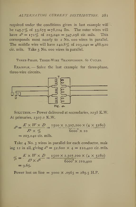
AL TERNA TING CURRENT DISTRIE UTION. 2 8 I
required under the conditions given in last example will
be 145.7% of 53,675 =78,204 lbs. The outer wires will
have d2 = 171% of 203,040 = 347,198 cir. mils. This
corresponds most nearly to 2 No. 000 wires in parallel.
The middle wire will have 240.8% of 203,040 = 488,920
cir. mils. Take 3 No. 000 wires in parallel.
Three-Phase, Three-Wire Transmission, 60 Cycles.
Example. — Solve the last example for three-phase,
three-wire circuits.
T
I So.D
Fig. 42.
Solution.— Power delivered at secondaries, 2238 K.W,
At primaries, 2307.2 K.W.
i^__K xW x D _ 1500 x 2,307,200 x (4 x 5280)
I? X °j 60002
X 10
= 203,040 cir. mils.
Take 4 No. 3 wires in parallel for each conductor, mak-
ing 12 in all, giving d2 = 52,600 X 4 = 210,400 cir. mils.
, _K XW X D __ 1500 X 2,307,200 X (4 X 5280)
&Xd2
= 9-6 5-
6000 X 210,400
Power lost on line = 3000 X .0965 = 289.5 H.P.
282 ELECTRICAL AND MAGNETIC CALCULATIONS.
E.M.F. lost = M * E *°1° = '-18X6000X9.65IOO IOO
= 683.2 volts.
Generator E.M.F. = 6683 + volts.
TW .679 X 2,307,2001= —=- = ——
—
, ° ' = 261 amperes.E 6000
Add \\°j f°r core loss, making /= 265 amperes.
. , A X WxKX U2
Copper required =—— -. -„—v* M £? X % X io6
9.06 X 2,307,200 X 1500 X (4 X 5280)2
^ 2~7
66000 X 9.65 X 10
= 40,259 lbs.
Three-Phase, Four-Wire Distribution, 60 Cycles.
Example.— The secondaries from transformers to
center of distribution are 500 feet long. The load con-
sists of 5 20 H.P. induction motors, 200 volts, and 1000
16 c.p., 115 volt lamps, \ ampere each. Allow about
1 1 volts drop on lighting side from transformers to center,
and 5 volts from center to motors. The motor efficiency
may be assumed at 80 per cent and power factor 80
per cent. The E.M.F. at distributing center between the
main wires is 205 volts. Determine the wiring as in pre-
vious examples.
Solution.— For the motors,
TX W .725 X 4 X 20 X 746/ =: — —- = J—^ —l— = 270.5 amperes.
1 E x eff
.
200 X .80 '°
For the lamps,
T X W .607 X (ioooX^X 115)I2 = —= 1 i l- ^ = i74.S amperes.±L 200/= I
x + I2 = 445 amperes.
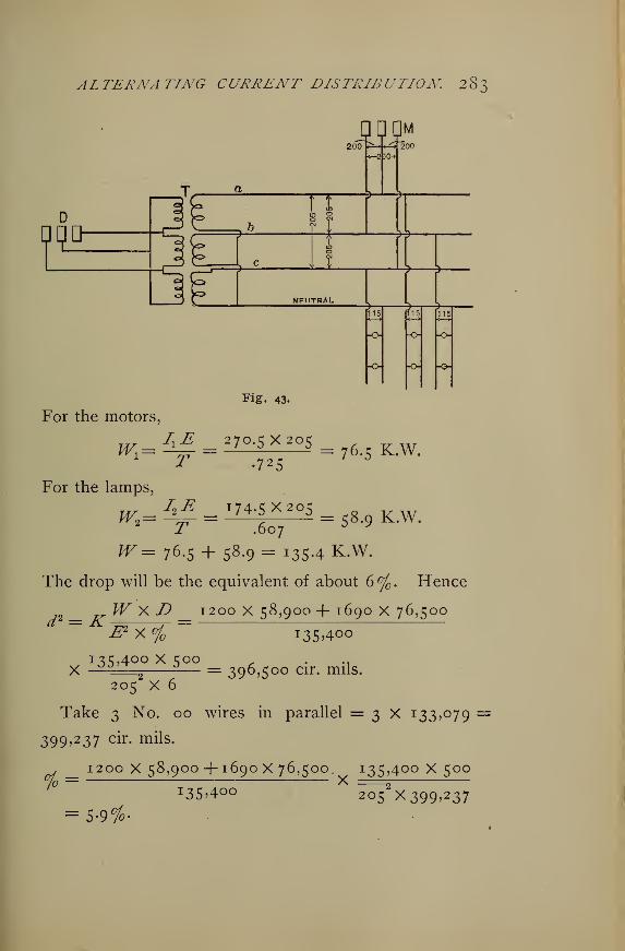
ALTERNATING CURRENT DISTRIBUTION. 283
nnnM200
nin 2
NEUTRAL
-o- -o-
n
-o -o
Fig. 43.
For the motors,
w _ A£ = 270-5x205 = 76>5 KWi725
For the lamps,
$B = ^74-5X205 = KW<y .607
^=76.5 + 58.9= I3S-4 K.W.
The drop will be the equivalent of about 6%. Hence
W X D 1200 x 58,900 + 1690 x 76,500d2 = K
135,400 X 500
i35>4-oo
= 396,500 cir. mils.
205 x 6
Take 3 No. 00 wires in parallel = 3 X I 33>°79 =
399,237 cir. mils.
_ 1200 x 58,900 + 1690x76,500 135^400 X 500jo — X o
= 5.9%.
135^400 2 °5 ^399,237
284 ELECTRICAL AND MAGNETIC CALCULATIONS.
,r 1 1 ,^ X °/o 1.62 X 205 X K.gVolts lost = M - = 5 ^_Z = Ig> 6.
100 100
E.M.F. at transformer secondaries = 205 + 19.6 =224.6 volts.
Drop to center measured between each main and the
neutral
= 19.6 x H# == I1 - 2 7 volts.
Cross section of neutral conductor need be only
d2 = }1±5_ x (3 X 133,079) = i55>5°° cir - mils -
445
Use No. 000 = 167,800 cir. mils.
Monocyclic, 60 Cycles.
Example.— The load consists of 4 20 H.P. no volt
induction motors, 85% efficiency, and 2000 half-ampere,
104 volt incandescent lamps. Distance of transformers
from generator, half a mile. Motors are 100 feet from
transformers, line loss 4%. Transformer efficiency 97%.Primary line loss 5%. No load E.M.F. of generator 1040
volts. Separate transformers are used for lights and
motors. Determine lines as before.
Solution.— At motors
4 X 20 X 746W = -—-— = 70,212 watts.0.85
For 80% power factor
t-WXjD ' 70,212X100 . .,
d2=K = 3380 X '! , =490,000 cir mils.
£2X°/o no2 X4
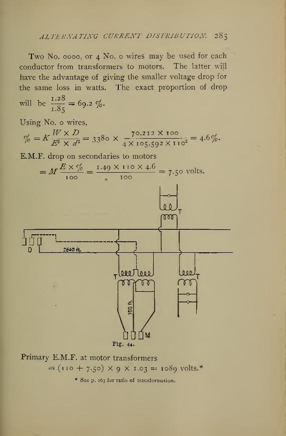
ALTERNATING CURRENT DISTRIBUTION. 285
Two No. 0000, or 4 No. o wires may be used for each
conductor from transformers to motors. The latter will
have the advantage of giving the smaller voltage drop for
the same loss in watts. The exact proportion of drop
.„ , 1.28 . ,
will be —— = 69.2 %.j
Using No. o wires,
, ^Wy.D 70,212x100 ,
# =KW*!> = ^° X4 X ,05,593 X no* = 4 -6 ^'
E.M.F. drop on secondaries to motors
.-jExtfo 1.49 Xi 10X4.6 .—M '— = —— — = 7.50 volts.100 100
UJUcm
iop:2640 ft
SLMJ
nro
Fig. 44.
Primary E.M.F. at motor transformers
= (no + 7.50) X 9 X 1.03 = 1089 volts.*
* See p. 163 for ratio of transformation.
286 ELECTRICAL AND MAGNETIC CALCULATIONS.
Hence E.M.F. at secondaries of lighting transformers,
1089 ,= -T- 1.03 = 105.7 volts.
Also at motor transformers
___ 70,212 X 1.046W ~Y7^ 7^V~= 7S ?
7i3 watts.(1.00 — .03)
At lighting transformers
2000 X^X 105.7 •W2= — = 108,970 watts.
0.97'*'
W' = 108,970 + 75,713 = 184,683 watts.
Total power factor
108.9 X .95 + 75-7 X .80=i8^"
- 88 %'
Hence ^ = 2160 -s- .88 =2424.
From primary circuit
. ^WxD 184,683 X 2640d2=K = 2424 X °
9—
E2 X % 10892
X 5
= 200,000 cir. mils.
Take 2 No. o wires in parallel, making
, 2424 X 184,683 X 2640oj =
2= 4.0.
1089 X (2 X 105,592)Primary drop
_MxE X °JC __ 108.9 X 1.30+75.7 Xi.49 1089 X 4-8
100 184.7 IO°
= 72 volts.
Generator E.M.F. = 1089 + 72 = 1161 volts.
^ T I l6l — I040 , ,
Compounding = = 11.6%.1040 '
_ TxW 1.099 X 184,683I = ^— = —s = 186 amperes.E 1089
r
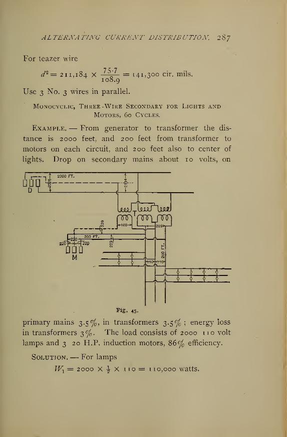
ALTERiYATIXG CURREXT DISTRIBUTIOX. 287
For teazer wire
211,184 X75-7 = 141,300 cir. mils.108.9
Use 3 No. 3 wires in parallel.
Monocyclic, Three -Wire Secondary for Lights andMotors, 60 Cycles.
Example.— From generator to transformer the dis-
tance is 2000 feet, and 200 feet from transformer to
motors on each circuit, and 200 feet also to center of
lights. Drop on secondary mains about 10 volts, on
i,. | 2000 FT.
On !fr
-i-Dl_J J_L_J
jujJZuLuUju.
: nnrrnnrLpm/gi |<+88->
|I « 229>r—
>
220 220
M
Fig. 45.
primary mains 3.5%, in transformers 3.5% ; energy loss
in transformers 3%. The load consists of 2000 no volt
lamps and 3 20 H.P. induction motors, 86% efficiency.
Solution.— For lamps
Wx= 2000 X \ X no = 110,000 watts.
, volts loss X IOO „ .%=—^r^— = 2 -8%
288 ELECTRICAL AND MAGNETIC CALCULATIONS.
For 10 volts secondary loss
s loss X
Therefore
79 T. W X D 110,000X200</* = X = 2400 x —=rs
-S2 X % 220 X 2.8.
= 389,610 cir. mils.
Take 3 No. 00 = 3 x 133,079 cir. mils.
, T^W X D 110,000 X 200% = K ,^ m = 24°° X ^~=* = 2 ' 7 '
dz x Ez399> 237 X 22 °
_ __^ X % 220 X 2.7Drop = Jf '— = 1.34 X = 9 volts.
100 100
Taking neutral = \ of outside = one No. 00.
E.M.F. at transformer secondary =229 volts.
In secondary lighting mains
T rnW 110,0007i= ^-et = 1-052 x = 526 amperes.
Amount of copper in 1400 feet of No. 00 = 666 lbs.
For motors
___ 20 x 746 X 3 ,2=
086= 52,°4
= 17,348 watts on each circuit.
In order to make the drop on motor circuits the same
as lighting mains for 80% power factor, the°f
drop
must be taken at about 3.5%. Hence
79 o I 7>348 X 200 . ..
d 2 = 3380 X \ = 70,210 cir. mils.
220 X 3.5
Take one No. 2 = 66,373 cu~- mils.
, KxWxD 17,348x200 , .
E2 X d2 220 X 66,373
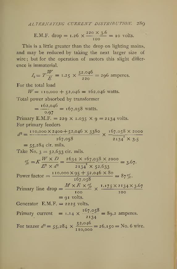
ALTERNATING CURRENT DISTRIBUTION 289
220 x ^ 6E.M.F. drop = 1.26 X — = 10 volts.
100
This is a little greater than the drop on lighting mains,
and may be reduced by taking the next larger size of
wire ; but for the operation of motors this slight differ-
ence is immaterial.
^W 52,046I2 = T— = 1.25 X = 296 amperes.
For the total load
W= 110,000 + 52,046 = 162,046 watts.
Total power absorbed by transformer
162,046= = 167,058 watts.0.97 " *
Primary E.M.F. = 229 X 1.035 X 9 = 2134 volts.
For primary feeders
110,000X2400+ 52,046x3380 167,058x2000
167,058 2i 3 42
X3.5= 55,284 cir. mils.
Take No. 3 = 52,633 cir. mils.
WxD 2634X167,058x2000% =K j?2 „ ^ = =2— = 3-67-E2 xd2 2134 X 52,633
_ , 110,000X95+52,046x80 . ,
Power factor = ^ V— = 87%.167,058 '
.. , MxEx°i 1.175 X2134X3JPrimary line drop = '- X —— ——
—
_ 6 7
100 100= 91 volts.
Generator E.M.F. = 2225 volts.
-r. • 167,058Primary current = 1.14 X —-—— = 80.2 amperes.
2134
For teazer d2 = 55,284 X ^-1 = 26,150 = No. 6 wire.009110,000 °
29O ELECTRICAL AND MAGNETIC CALCULATIONS.
65. Original Problems. — 1. Neglecting the effect of
induction calculate the size of the primary mains and also
the secondary leads of a large transformer fully loaded
constantly, whose efficiency may be taken at 98%. Thesecondaries run 200 feet to feed 1000 lamps at 5% loss.
The primaries run \ mile at 5 % loss. The ratio of trans-
formation is 20. The lamps are no volts. Determine
voltages and capacities.
Secondaries a No. 0000 and a No. 000 wire.
Primaries No. 10 wire.
Voltage at secondary terminals 116 volts.
Voltage at primary terminals 2340 volts.
Secondary current 500 amps., primary 2.53
amps.
Machine volts 2463, primary drop 123 volts.
Machine capacity 65 K.W.
Transformer capacity 60 K.W. ; lights 55 K.W.
2. A machine of 60 K.W. capacity is to supply two
fully loaded transformers at an average of f mile. The
secondaries are respectively 200 feet for § total load, and
100 feet for \ total load. Losses are 5% on secondaries,
5% on primaries. Transformer efficiencies, 97% for the
larger, 96% for the smaller. Determine capacity of trans-
formers and lights ; also the sizes of primary and second-
ary wires. The ratio is 10.
Load at transformers 57 K.W.Secondary, larger, 37 K.W., smaller, 18 K.W.
Load lamps 52 K.W. Primary wire No. 2.
f a No. o and a No. 00 in
Secondary wire -\ parallel on larger. No. 2
wire on smaller.
ALTERNATING CURRENT DISTRIBUTION. 29
1
3. A load of 1000 incandescent no volt lamps is put
on the transformer secondaries ; the transformers are of
nearly one size and are so loaded that about S c/ will
represent the inductance loss and 1°f
the resistance loss.
The core loss will be 5%. Also 4% line loss is allowed
in the secondary wiring. The primary wire is 5 miles long,
18 inches apart, and is No. 00, carrying the current at
125 cycles. Determine the generator volts, transformer
pressure, both primary and secondary ; also the ohmic
and inductive drops. Ratio 10.
Voltage 1 100.
Current 50 amperes.
Secondary ohmic drop 44 volts.
Secondary inductive drop 3%, 33 volts.
Transformer ohmic drop 1%, n volts.
Transformer inductive drop 8°f0y 88 volts.
Core loss 5% of 50 amperes = 2.5 amperes.
/(total) = 52.5.
Line ohmic drop= (0.4 1 2 X 10) X 52.5 = 2 16.3 volts.
Line inductive drop = (1.23 X 10) x 52.5
= 645-75 + 15% = 742.6 volts.
Total active volts = 1100 + 44 + n + 216.3
= I 37 1 -3-
Total inductive volts = 33+88 + 742.6 = 863.6.
Total impressed volts = ^li^i.^ + 863.
6
2
= 1626 volts.
Generator apparent watts = 84365.
Secondary impressed volts = V11442 + 332
= 1 144.5 v°lts.
Primary impressed volts = vnj^ 2 + 1212
= 1 1 61.3 volts.
292 ELECTRICAL AND MAGNETIC CALCULATIONS.
4. A long-distance plant generates about 1200 volts,
steps up to about 12,000, carries the power over 16 miles
of No. 1 wire to sub-station, where it is transformed down
to about 1000 volts, then carried over wires and distances
equivalent to 2 miles of No. 000 wire, then transformed
for consumers to 100 volts. The frequency is 60 and the
ratio of transformation is 10. Assume a power factor in
the secondaries and lamps of 98.5, thus giving an induc-
tance factor of 17. Allow 1% ohmic loss in all trans-
formers and 6°/ average inductive drop. These per cents
are taken on secondary voltages. Core losses are figured
at 3%. If the energy delivered is equivalent to 9000
lamps at 50 watts each, make the calculation of pressures
and generator energy.
In terms of high voltage line the secondary E.M.F. is
10,000 volts and the current is 50 amperes.
Active secondary E.M.F. = 98.5% of 10,000
= 9850 volts.
Inductive secondary E.M.F. = 17% of 10,000
= 1700 volts.
Step-down transformers,
Ohmic drop \°j of 10,000 =100 volts.
Ind. drop 6% of 10,000 = 600 volts.
Core loss 3% of 50 amperes = 1.5 amperes.
Total current in primaries = 50+ 1.5 = 51.5 amp.
Primary impressed E.M.F.
£{= V(985o +ioo)2+ (i7oo+ 6oo)2 =io,2i2
volts.
Line between step-down transformers,
Ohmic drop = (0.324 X 4) X 51.5 = 67 volts.
Ind. drop = (0.607 X 4) X 51.5 = 125 volts.
ALTERNATING CURRENT DISTRIBUTION 293
Total voltage at secondaries, step-downs,
EL= Vio,oi7
2 + 2425s = 10,306 volts.
First step-down transformers,
Ohmic drop = i cfc of 10,306 =103 volts.
Inductive drop = 6 c/ of 10,306 = 618 volts.
Volts impressed on primaries, step-downs,
Et= v IO,i2o
2 + 3043 = 10,572 volts.
Current in long-distance line,
/= S 1 ^ + 3c/o of 51.5 = 53 amperes.
Long-distance line,
Ohmic drop = (0.65 X 32) x 53 = 1 100 volts.
Ind. drop = (0.65 X 32) X 53 = 1100 volts.
Voltage at secondaries, step-ups,
11,220 +4143 = 11,998 volts.
Step-up transformers,
Ohmic drop = i°/ of 11,998 =120 volts.
Inductive drop, 6% of 11,998 = 720 volts.
Primary impressed pressure,
Et= Mi,34o
2 + 4863s = 12,339 volts.
Primary current from machine,
I== 53 + 3c/o oi S3 = 54-6 amperes.
Apparent power = 674 K.W. Lag 23 . Cos 23
= 0.918, total power factor.
True power = 674 x 0.918 = 618.7 K.W.Total transmission loss
= 618.7 — (9.000 X 50) = 163.7 K.W.Total per cent transmission loss
= 163.7 -J- 618.7 = 26.46%.
. Solve problem 5, page 80, by the formulae of 64.
294 ELECTRICAL AND MAGNETIC CALCULATIONS,
6. Determine the wiring for the following single-
phase, 125 cycle circuit. From generators to trans-
formers 2000 feet, loss about 5% of delivered power.
Transformer drop 3%, energy loss 3%. Drop in sec-
ondary wiring 2 volts. Ratio of transformation 10 to 1.
Load consists of 1000 16 c. p. 3.6 watt, 104 volt lamps.
Wire No. 3 B. & S.
Primary drop = 68.4 volts.
Generator E.M.F. = 1160.
Primary current = 58.3 amperes.
7. The distance from generator to transformer is
2500 feet, loss 5%. Ratio of transformation 20 to 1;
efficiency of transformer 97-3-%, voltage drop 2%. Sec-
ondary loss 2 volts. Load 750, 52 volt 60 watt lamps.
Determine the wiring, etc., for a single-phase, 60 cycle
system.
Wire No. 3 B. & S.
Primary drop = 54 volts.
Generator E.M.F. = 1155.4 volts.
Primary current = 44.8.
8. Calculate the transmission circuit for a two-phase,
four-wire, 60 cycle system to deliver 2500 H.P. 5 miles
at 6000 volts, line loss 7^%. Load consists of induction
motors. Efficiency of transformers 97^%.
Wire 3 No. o B. & S.
Line loss = 574 volts.
Generator E.M.F. = 6574 volts.
I= 199 amperes.
Core loss = 3 amperes.
ALTERNATING CURRENT DISTRIBUTION 295
9. In a two-phase, four-wire system, 125 cycles, 5000
H.P. is transmitted si miles at IO% loss - The E.M.F.
at transformers is 5000 volts, and the load has a power
factor of about 85%. Determine the size of wire and
generator E.M.F.
Wire 4 No. o B. & S.
Line loss = 9.79%.
E.M.F. drop = 1042.6 volts.
Generator E.M.F. = 6042.6 volts.
10. Solve 8, assuming a three-phase, 60 cycle trans-
mission circuit.
Wire 3 No. o B. & S.
Line drop = 574 volts.
Generator E.M.F. = 6574 volts.
/= 237.5 amperes.
11. Solve 9 again, assuming the same conditions for a
three-phase circuit, three-wire, but having a frequency of
60 cycles instead of 125.
Line 4 No. o wires.
Drop = 646 volts.
Generator = 5646 volts.
/ = 514 amperes.
12. A three-phase, 60 cycle, four-wire system of distri-
bution is to be constructed to supply a load of 750 115
volt lamps, and 4, 16 H.P., 200 volt induction motors.
From transformers to center of distribution the distance
is 600 feet. There are to be 15 volts drop on lighting
circuits between transformers and center, and five volts
from center to motors. The motor efficiency will be about
85%, and E.M.F. at the center about 205 volts.
296 ELECTRICAL AND MAGNETIC CALCULATIONS
Lamp circuits 2 No. o wires.
Drop = 26.4 between mains, or 15.2
between mains and neutral.
Neutral wire = No. 1 B. & S.
For motors, current =191 amperes.
For lamps, current =191./= 392 amperes.
13. At a distance of 3000 feet from the generator a
transformer is stationed to supply 1500 half ampere, 104
volt lamps and one 25 H.P. no volt induction motor,
efficiency 85%, system monocyclic. From transformer to
motor the distance is 100 feet, loss 2^%. Efficiency of
transformers 97%. Primary loss 4%. Determine the
wiring, etc, as before, frequency 60 cycles.
Motor circuit 2 No. o wires.
Drop in motor circuit = 4 volts.
Lighting circuits No. 000 B. & S.
Drop primary circuits = 68.5 volts.
Generator E.M.F. = 1 144.5 volts.
1= 106 amperes.
Teazer No. 4 B. & S.
14. A load of four 10 H.P. induction motors at a dis-
tance of 200 feet from transformers, and 1000, no volt
lamps, 16 c. p., at a distance of 150 feet from trans-
formers, fed by a three-wire secondary system, mono-
cyclic, 60 cycles, are supplied with power by a generator
1000 feet from transformers. If the primary drop is to
be about 3% and the drop in secondary circuits about 10
volts, determine the wiring, etc., assuming transformer
drop 4% and energy loss 3%.
ALTERNATING CURRENT DISTRIBUTION 2g)
For motor circuits, wire is No. 5 B. & S.
Volts loss = 8.25. E.M.F. = 220 volts.
For lights, wire = No. 000 B. & S.
Drop = 8 volts. E.M.F. = 220 volts.
Neutral = No. 2 B. & S.
Primary feeder = No. 7 B. & S. Teazer
= No. 8.
Primary current = 48.8 amperes.
Primary drop = 58.5 volts.
Generator E.M.F. = 2192.5 volts.
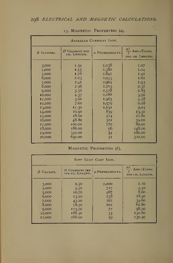
298 ELECTRICAL AND MAGNETIC CALCULATIONS.
13. Magnetic Properties (a).
Annealed Charcoal Iron.
B Gausses.H Gilberts per
cm. Length. /x Permeability. -j- Amp.-Turns
per cm. Length.
3,000 i-34 2,238 I.07
4,000
5,000
i-55
1.76
2,580
2,841
I.24
1.41
6,000 2.03 2 >955 I.62
7,000 2.41 2,904 i-93
8,000
9,000
2.96
3-56
2,703
2,528
2-37
2.85
10.000
1 1 ,000
12,000
4-375.60
7.60
2,288 .
1.963
1.579
3-5°
4486.08
13,000 11.30 1,151 9.04
14,000
15,000
16.90
28.60839524
13.5022.80
16,000 48.80 321 39.00
17,000 100.00 170 80.00
18,000 186.00 96 148.00
19,000 350.00 54 280.00
20,000 650.00 3 1 520.00
Magnetic Properties (b).
Soft Gra^ Cast Iron.
B Gausses.H Gilberts perper cm. Length.
/a Permeability.—j- Amp .-Turns
per cm. Length.
3,000 I.50 2,000 I.20
4,000 5-50 727 4.40
5,000 IO.70 467 8.60
6,000 23.20 258 18.50
7,000 43.20 162 34.60
8,000 78.50 102 62.80
9,000 123.70 72 98.90
10,000 188.50 53 150.80
1 1 ,000 288.OO 39 230.40
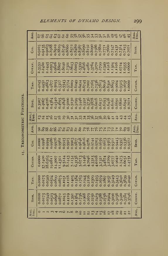
ELEMENTS OF DYNAMO DESIGN. 299
CO
53
Oi-h
HO
U1—
1
u
oz
3H
<r^NO >OTj-fON t-i O O00 t^vO "Tt nw ** O Onoo t^vO toVONO^NONO^ONONO iOiO»O lO»OiO>OiO»OiOi, Tl"'tTj, Tf
o 6
in
OU
10 to cooo O OnNO ONOr^OwOvOOi-<Ot^HHTtroi-<O conO 00 hh M Tfv£> t^ 00 00 ON Q\ ONOO 00 r^vo t^M o\nM >-i O On OnOO t^NO ^"t COM hh O OnOO r^VO ^rffOH Oon on Onoo oooooooooooqoqoqoooq r>»r^r^r^t^r>»r^t^r^66666666666666 6 6 6 6 6 6 6 6 6
H
72
<H
U
OO "^ conO t^ O *•* fO co OnNO h rfO O O\00 tJ-nO rj- to Ow-j\o "^ O N O tj-n ^"O OnMOOVO r^O\"3->-< O O N »00lO^j- -t tONO 00 O ^OnO O fOOO M t^ N NCOO>Om NfOOrow m q Onoo oq r^»NO Nq^^^cocowNi-<>-ii-<oOo H
<
low rON«Ors n^tO\ON-tuiN *>">vO cooo •-" mrJ-^NOTt w-ivO tN Osm Tj-r>,o tJ-OstJ-o^O CO i-" On On On O N ^O On ^vo 00 O fO"^NO N Tfr^O N tnoo O cono O conO O1" "* "t 1" ^ °? ^ ^9^ ^ ^ ^ r^ r^ t^ r^oo oo oo On On On O60000000000000' dddddo' dciw
<HOU
C/2
r^ t^vo Tf O ^ooo O O OnnO nvOoooo n cooo >-> ~> O i^» |-1
O no moo ^ CN't O ^ON-t OsfONH ^n a\ n \Q On n tJ- r^OnO n co ^ovo 00 O "-i n Tfior^oo o *-" n 't h\ooo OOrOTj-Tj-Tj-Tf'^-'^-i-oi-ovnvovotn lovq O \D ^O 'O \0 ^ *0 r>»
oodo'o'o'oddddddoo'ddddoddd
wz
U
CO rf *ONO t^00 On O i-c m ro rf *OnO r^OO On O •* N CO Tf to C3
<
6z O Onoo r^vo ""> rf co m hh onoo r^vo- *o Tf CO M t-i O OnOO
onoo 000000000000000000 t^t^.t^r^t>»t^r^r^t^ t^vo voo 6
(A
U
O 00 rfvO NO N to to co 1^00 NO hh tJ- co On co co "-" "^ r^NO N
mOOOOOOOOOOOOOOO 0000000H
<HOu
O O f^H nh rj-ro Tj-00 CONO NO tOOO i-h rJ-ONt^N i^m i-h
O ONO hi O O rf" rj- VOCOH tTtJ-i-i O N t^O N^j-N 1^ 1^O ^J- cooo O CO "-H TfM hh NrfO com COCO r>. t^ O Tt- O r^O ^ NO O ^ "<f ^ •-; hH ro^ i-h NroO r^ tJ- « On r^NO ^f
O r^od on tj- « onoo' rA.vo" lo io444cofoncoN ci c4 nIO M HH M HH
<
<
O «oO\Tt qn^moo lOrfco Tf no ONCoONr^r^ONcoO OOO hh ro iONO 00 O N -"tiONONH CO rJ-NO 00 O M -^-NO 00 OOOOOOOhhi-ih-ii-ihhi-iWMMMNCOCOCOCOCO'^-666666666666 6 6 6 6 6 6 6 6 6 6 6
<HCU
C/3
Q »0 0> COOO N to On m tJ-nO 00 On O OnOO VO ^OVO O "^"^O t^Tj-M ONt^Tt"-! ONNO COO NIOmOO »om OMONOO -^t
O m fO lONO 00 O N rO^NO\0 M 'tiONCNO M rJ-iOt^oqpoqoMHHMHHWMC^MNMNMcocpcococo66666666666666666666666 OU
6 a o h n f^Tj- vono r^oo ono h n nt lONO t^00 ONO h NHH h-t t-H H4I-IMHHI-II-II-CC4MM
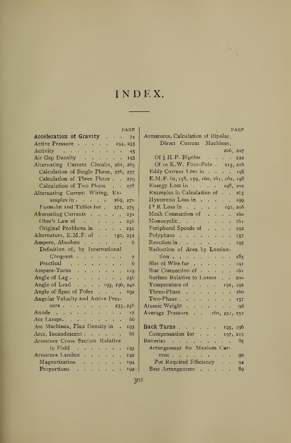
INDEX
PAGE
Acceleration of Gravity ... 74
Active Pressure 234, 235
Activity 45
Air Gap Density 193
Alternating Current Circuits, 261, 265
Calculation of Single Phase, 276, 277
Calculation of Three Phase . . 279
Calculation of Two Phase . . 278
Alternating Current Wiring, Ex-
amples in 269, 270
Formulas and Tables for . 272, 275
Alternating Currents 230
Ohm's Law of 236
Original Problems in .... 251
Alternators, E.M.F. of . . 150, 232
Ampere, Absolute 6
Definition of, by International
Congress 7
Practical 6
Ampere-Turns 113
Angle of Lag 236
Angle of Lead .... 195, 196, 240
Angle of Span of Poles .... 192
Angular Velocity and Active Pres-
sure 235, 236
Anode 17
Arc Lamps 66
Arc Machines, Flux Density in . 193
Arcs, Incandescent 66
Armature Cross Section Relative
to Field 193
Armature Lamina? 192
Magnetization 194
Proportions 192
PAGEArmatures, Calculation of Bipolar,
Direct Current Machines,
206, 207
Of JH. P. Bipolar .... 222
Of 10 K.W. Four-Pole . 215, 216
Eddy Current Loss in ... . 198
E.M.F. in, 158, 159, 160, 161, 162, 198
Energy Lost in ... . 198, 202
Examples in Calculation of . . 163
Hysteresis Loss in 199
I 2 R Loss in 191,208
Mesh Connection of .... 160
Monocyclic 161
Peripheral Speeds of .... 192
Polyphase 157
Reaction in 195
Reduction of Area by Lamina-
tion 185
Size of Wire for 191
Star Connection of 161
Surface Relative to Losses . . 200
Temperature of ... . 191, 192
Three-Phase 160
Two-Phase 157
Atomic Weight 98
Average Pressure . . 160, 231, 232
Back Turns 195, 196
Compensation for . . . 197, 213
Batteries 85
Arrangement for Maxium Cur-
rent 90
For Required Efficiency . . 94
Best Arrangement 89
3OI
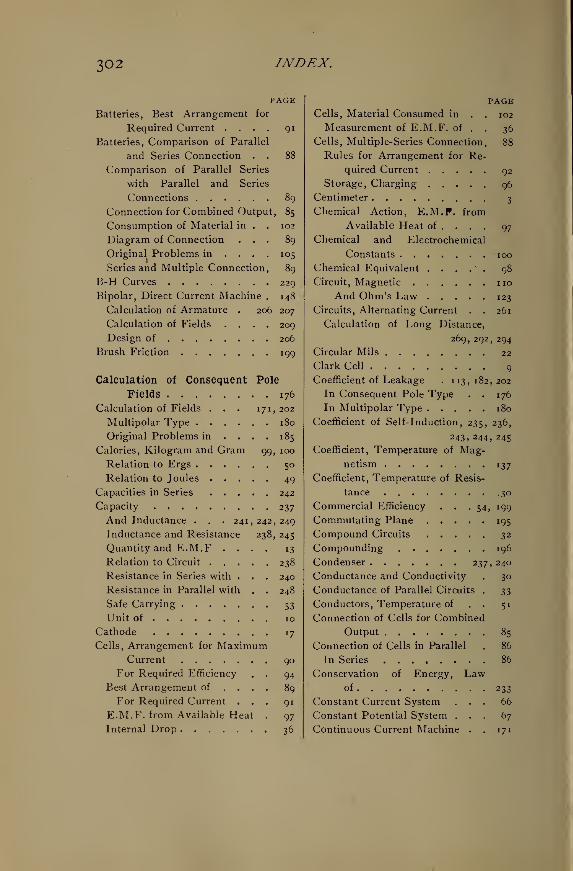
302 INDEX.
PAGE
Batteries, Best Arrangement for
Required Current .... 91
Batteries, Comparison of Parallel
and Series Connection . . 88
Comparison of Parallel Series
with Parallel and Series
Connections 89
Connection for Combined Output, 85
Consumption of Material in . . 102
Diagram of Connection ... 89
Original Problems in ... . 105
Series and Multiple Connection, 89
B-H Curves 229
Bipolar, Direct Current Machine . 148
Calculation of Armature . 206, 207
Calculation of Fields .... 209
Design of 206
Brush Friction 199
Calculation of Consequent Pole
Fields 176
Calculation of Fields . . . 171, 202
Multipolar Type 180
Original Problems in .... 185
Calories, Kilogram and Gram 99, 100
Relation to Ergs 50
Relation to Joules 49
Capacities in Series 242
Capacity 237
And Inductance . . . 241,242,249
Inductance and Resistance 238, 245
Quantity and E.M.F .... 13
Relation to Circuit 238
Resistance in Series with . . . 240
Resistance in Parallel with . . 248
Safe Carrying 53
Unit of 10
Cathode 17
Cells, Arrangement for MaximumCurrent 90
For Required Efficiency . . 94
Best Arrangement of ... . 89
For Required Current ... 91
E.M.F. from Available Heat . 97
Internal Drop 36
PAGECells, Material Consumed in . . 102
Measurement of E.M.F. of . . 36
Cells, Multiple-Series Connection. 88
Rules for Arrangement for Re-
quired Current 92
Storage, Charging 96
Centimeter 3
Chemical Action, E.M.F. from
Available Heat of ... . 97
Chemical and Electrochemical
Constants 100
Chemical Equivalent . . . . . 98
Circuit, Magnetic noAnd Ohm's Law 123
Circuits, Alternating Current . . 261
Calculation of Long Distance,
269, 292, 294
Circular Mils 22
Clark Cell 9
Coefficient of Leakage . 113,182,202
In Consequent Pole Type . . 176
In Multipolar Type 180
Coefficient of Self-induction, 235, 236,
243, 244, 245
Coefficient, Temperature of Mag-netism 137
Coefficient, Temperature of Resis-
tance .30
Commercial Efficiency . . .54, 199
Commutating Plane 195
Compound Circuits 32
Compounding . 196
Condenser 237, 240
Conductance and Conductivity . 30
Conductance of Parallel Circuits . 33
Conductors, Temperature of . . 51
Connection of Cells for Combined
Output 85
Connection of Cells in Parallel . 86
In Series 86
Conservation of Energy, Lawof 233
Constant Current System ... 66
Constant Potential System ... 67
Continuous Current Machine . . 171
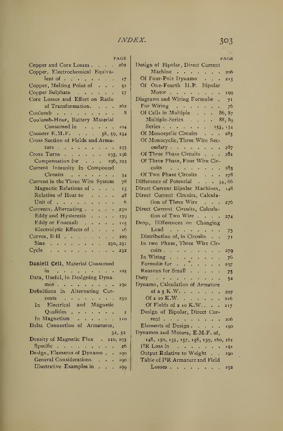
INDEX. 303
PAGE
Copper and Core Losses .... 262
Copper, Electrochemical Equiva-
lent of 17
Copper, Melting Point of . . . 51
Copper Sulphate 17
Core Losses and Effect on Ratio
of Transformation. . . . 262
Coulomb 8
Coulomb-Hour, Battery Material
Consumed in 104
Counter E.M.F. ... 58, 59, 234
Cross Section of Fields and Arma-
ture 193
Cross Turns 195, 196
Compensation for . . . 196, 213
Current Intensity in CompoundCircuits 34
Current in the Three Wire System 78
Magnetic Relations of ... . 15
Relation of Heat to . . . . 48
Unit of 6
Currents, Alternating 230
Eddy and Hysteresis . ... 139
Eddy or Foucault 115
Electrolytic Effects of ... . 16
Curves, B-H 229
Sine 230, 231
Cycle 232
Daniell Cell, Material Consumedin 103
Data, Useful, in Designing Dyna-
mos 190
Definitions in Alternating Cur-
rents 230
In Electrical and Magnetic
Qualities 1
In Magnetism noDelta Connection of Armatures,
32, 52
Density of Magnetic Flux . no, 193
Specific 26
Design, Elements of Dynamo . . 190
General Considerations . . . 190
Illustrative Examples in ... 199
PAGEDesign of Bipolar, Direct Current
Machine 206
Of Four-Pole Dynamo . . . 215
Of One- Fourth H.P. Bipolar
Motor 199
Diagrams and Wiring Formulae . 71
For Wiring 76
Of Cells in Multiple . . . 86, 87
Multiple-Series .... 88, 89
Series 153, 154
Of Monocyclic Circuits . . . 285
Of Monocyclic, Three Wire Sec-
ondary 287
Of Three Phase Circuits ... 281
Of Three Phase, Four Wire Cir-
cuits 283
Of Two Phase Circuits ... 278
Difference of Potential . . . 34, 66
Direct Current Bipolar Machines, 148
Direct Current Circuits, Calcula-
tion of Three Wire . . . 276
Direct Current Circuits, Calcula-
tion of Two Wire .... 274
Drop, Differences on Changing
Load 75
Distribution of, in Circuits . . 71
In two Phase, Three Wire Cir-
cuits 279
In Wiring 76
Formulae for . 197
Reasons for Small 75
Duty 54
Dynamo, Calculation of Armature
of a 5 K.W 207
OfaioK.W 216
Of Fields of a 10 K.W. ... 217
Design of Bipolar, Direct Cur-
rent 206
Elements of Design 190
Dynamos and Motors, E.M.F. of,
148, 150, 153, 157, 158, 159, 160, 161
I2R Loss in 191
Output Relative to Weight . . 190
Table of I 2R Armature and Field
Losses 192
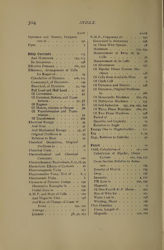
304 INDEX.
PAGEDynamos and Motors, Tempera-
ture of 191
Dyne 2
Eddy Currents 115
And Hysteresis .... 139, 215
In Armatures 198
Effective Pressure .... 160, 232
Efficiency, Arrangement of Cells
for Required 94
Calculation of Dynamo . 206, 215
Commercial, of Dynamos . . . 199
Electrical, of Dynamos . . 54, 199
Full Load and Half Load ... 57
Of Conversion 54Of Dynamos, Motors, and Trans-
formers 57, 58Of Engines 57Of Motors, relation to Output . 59
Of Transformation and Trans-
mission 54Of Transformers 262
Electrical Energy 45
And Heat 47
And Mechanical Energy . . 45,46
Original Problems in ... . 59
Relation to Heat 99
Electrical Quantities, Original
Problems in 18
Electrical Units 6
Electrochemical and Chemical
Constants 100
Electrochemical Eq uivalents , 8 ,1 7 , 1 8 , 99
Electrolytic Effects of Currents . 16
Electromagnetic Units .... 6
Electromotive Force, Unit of . . 8, 9
Electrostatic Units 6
Elements of Dynamo Design . . 190
Illustrative Examples in . . . 199
Useful Data in 190
E.M.F. and Heat of Cells ... 100
And Magnetic Flux 148
And Rate of Change of Lines of
Force 234, 242
Average 231
Counter 58 > 59> 234
PAGEE.M.F., Frequency of 232
Generated in Armatures . . . 198
In Three Wire System .... 78
Maximum 232, 234
Measurement of Drop of, in
Cells 36
Measurement of, in Cells . . 36
Of Alternators ...... 150
Of Bipolar Direct Current Ma-chines 148
Of Cells from Available Heat . 97
Of Clark Cell 9
Of Dynamos and Motors . . . 148
Of Dynamos, Original Problems
in 166
Of Monocyclic Machines . 162, 163
Of Multipolar Machines . . . 153
Of Self-induction 233, 234, 243, 244
Of Three Phase Machines 160, 161
Of Two Phase Machines ... 158
Period of 232
Quantity and Capacity .... 13
Relation to Angle 230
Energy Due to Magnetization . . 11
1
Erg 2,45
Ergs, Relation to Calories ... 50
Farad 10
Field, Calculation of . . . 171, 202
Calculation of Bipolar, Direct
Current .... 202, 209, 217
Cross Section Relative to Arma-
ture 193
Density of Flux in 193
Drop 197
Intensity 4, " r
I 2R Loss in 191, 192
Magnetic 4
Of One-Fourth H.P. Motor . . 222
Size of Wire for 191
Watts Lost in ....... 198
Winding, Shunt 196
Flux densities 193
Lines, Length of 205
Magnetic ...... no, 120
INDEX. 305
PAGE
Foot-Pound 45
Force, Law of Magnetic .... 116
• Lines of 4
Magnetizing 113
Magnetomotive 112
Formulae and Diagrams for Wir-
ing 71
And Tables for Alternating
Current Wiring 272
For Efficiency of Cells ... 95
Simplified for Wiring .... 74
Useful in Designing .... 197
Foucault Currents 115
Four-Pole Dynamo, Calculation
of Fields of 217
Design of 215
Frequency of Alternating E.M.F.
232, 233
Friction of Brushes 199
Fuse Wire, Size of 52
Gausses no, mGeneral Laws of Resistance . . 22
Geometric Sum 246
Gilberts 112
Gram-Degree 49
Gravity, Acceleration of ... . 47
H 4 . 4, in, 113
Heat and Electrical Energy . . 47, 99
E.M.F. of Cells from Available,
97, 100
Rate of Radiation of ... . 51
Relation to Current .... 48
To E.M.F 48
To Mechanical Work ... 49
To Resistance 48
Unit of 49
Heats of Formation and Separa-
tion 102
Henry 11,237
Horse Power J i,45
Hydrogen, Electrochemical Equiv-
alent of 18
Hysteresis and Eddy Currents , . 139
PAGEHysteresis Loss in Armatures . . 199
Magnetic u 4
Illustrative Examples in Dyna-mo Design 199
Impedance 236, 263
Factor 268
Impressed E.M.F. and Inductance 268
Pressure 234, 236
Incandescent Arcs 66
Inductance, Capacity and Resist-
ance 238, 245
And Capacity in Parallel . . . 249
In Series 241
And Resistance in Parallel 245, 246
In Series 238, 239
Factor of Line .... 267, 268
Unit of 237
Inductances in Parallel . . 246, 249
Series 239
Induction, Coefficient of ... . 235
Magnetic 5, noMutual 233
Self 233, 234
Unit of nInductive Pressure .... 234, 263
Resistance 235, 236
Intensity of Current in Com-pound Circuits 34
Of Magnetic Field inOf Magnetic Flux noAnd Strength of Field . . . 120
Of Magnetization 5
International Ampere 7
Ohm 10
Volt 9
Ions 101
Heat of 102
I 2 R Loss in Armatures . . 192, 208
In Dynamos 192
Joule 49
Joule's Equivalent . . . . 49, 99
Joules J 1, 46
Relation to Calories , , , . 49
3o6 INDEX.
PAGEKilogram 3
Kilogramme des Archives ... 3
Kilogram-Meter 45
Kilowatt 45
I* 243, 245
Lag, Angle of 236
Caused by Line Inductance . . 267
Of E.M.F. of Self-induction . 234
Of Magnetism 114
Laminae of Armature . . 185,192,201
Lamp-Feet 73
Lamps, Arc and Incandescent . . 66
Poor Economy of 50 Volt . 76, 77
Law of Conservation of Energy . 233
Of Magnetic Force 116
Of Resistance ....... 22
Ohm's 16
Lead, Angle of ... . 195, 196, 240
Leads and Lamp Circuits, Calcula-
tion of 67, 76
Size of 66
Leakage, Coefficient of . . 113,202
Magnetic 113
Length and Area, Relation to Re-
sistance 22
Lenz's Law 233
Leyden Jar 11
Lifting Power of Magnets . . . 132
Thompson's Rule for . . 134, 135
Light and Power, Wiring for . . 66
Lights and Motors, Wiring Mono-cyclic Circuits for ... . 287
Lines of Force 4
Lines of Force and Current . . . 242
And E.M.F 243
Formula for . 243
Rate of Change of 234
Long Distance, Calculation of
Circuits for . . . 269, 270, 293
Loss in Armature 192, 202
I'2 R in Armature and Field . . 202
Plant 54
Machines, Bipolar Direct Cur-
rent 148, 171
PAGEMachines, Consequent Pole Type, 176
Magnetic Circuit and Ohm's Law, 123
Magnetic Field 4Intensity of m
Magnetic Force, Law of . . . . n6Measurement of . . . 115,118,119
Magnetic Flux .110Density of noIntensity of, and M.M.F. . . 114
Intensity of Magnetism and
Strength of Field . . . 120
Lag of 114
Leakage of 113
Magnetic Hysteresis . . . . . 114
Magnetic Induction 5
Magnetic Moment5
Magnetic Properties, Table of, 229, 298
Magnetic Quantities, Original
Problems in J40
Relation of 116
Magnetic Relations of Current . 15
Magnetic Reluctance 112
Magnetic Units 4
Magnetism and Temperature . . 137
Remanent or Residual ....114Units and Definitions in . . . no
Magnetization of Armature . . . 194
Energy Due to inIntensity of ....... 5
Magnetizing Force 113
Magnetomotive Force 112
Magnets, Lifting Power of . . . 132
Thompson's Rule for . 134, 135
Saturated 114
Manganin 28
Mass 3
Material Consumed in Cells . . 102
Maximum Current, Arrangementof Cells for 89, 90
Maximum E.M.F. in Two Phase,
Three Wire Circuits . . . 280
Maxwells of Flux . ...... noMaxwell's Formula inMechanical Work, Relation to
Heat 49Megohm 10
INDEX. 307
PAGE
Mesh Connection of Armatures . 160
Formula for E.M.F. of ... 160
Meter 2
Meter des Archives 2
Microcoulomb 8
Microfarad 10
Microhm 10
Mil 22
Mil-Foot 22
Millimeter 3
Minimum E.M.F. in Two Phase,
Three Wire Circuits . . . 280
Monocyclic Armatures . . . . 161
E.M.F. of 162
Monocyclic Circuits 284
Connection of Transformers in . 162
Three Wire Secondary .... 287
Winding of Transformers for . 163
Motor, Calculation of Armature of
\ H.P 200, 222
Of Fields 202
Design of \ H.P 199
Of \ H.P 222
Pump, Power for 65
Motors, E.M.F. of 148
Output and Efficiency of . . 58, 59
Power Factor of 268
Multiple Connection of Cells . . 86
Multiple-Series Connection of
Cells 88
Compared with Multiple and
Series 89
Multiple Winding ." . . . 153, 154
Multipolar Dynamo, E.M.F. of . 154
Multipolar Type 180
Coefficient of Leakage of . . . 180
Mutual Induction 233
Neutral Wire 78, 79
Non-inductive Loads and Line
Induction 265
Number of Turns and E.M.F . . 242
Oersted . 112
Ohm 10
PAGEOhm, International 10
Ohmic Resistance 236
Ohm's Law 12
And the Magnetic Circuit . . 123
Ohm's Law Applied to the Electric
Cell 85
Of Alternating Current Circuits, 236
Ordinates 230
Original Problems in Alternating
Currents 251
In Alternating Current Distribu-
tion 290
In Batteries 105
In Calculation of Fields . . . 185
In Electrical Energy .... 59
In E.M.F. of Dynamos . . . .166
In General Laws of Resistance . 36
In Relation of Electrical Quan-
tities . 18
In Relation of Magnetic Quan-
tities 140
In Wiring 80
Output of Dynamos, Relation to
Weight 190
Over-Compounding 197
Calculation of 214
Oxygen, Chemical Equivalent of . 98
Electrochemical Equivalent of . 99
Parallel Circuits 32
Conductance of 33
Resistance of 33, 245
Parallel Connection of Cells . . 87
Parallel System 67
Period of an Alternating E.M.F., 232
Peripheral Speeds of Armatures . 192
Permeability 5, 112, 243
Permeameter Method 121
Permeance 5
Phase 235
Plant Efficiency 54
Pole, Strength of 4, 116
Unit 4, 115
Polyphase Armatures, 157, 159, 160, 161
Calculation of . . . , 163,164,166
3o8 INDEX.
PAGEPotential, Difference of ... . 34
Drop of, and Resistance ... 34
And Size of Leads .... 66
Power and Work 14
Power Factor of Line 267
With Motors - . 268
Power of Magnets 132
Required for Car . . . 57,58,65For Pump . 65
Unit of 11
Pressure, Active . . . . 234, 235
Average 150,231
Due to Capacity 237
Effective 150, 232
Impressed 234, 237
Self-Inductive .... 234, 243
Problems in Alternating Currents, 251
In Alternating Current Distribu-
tion 290
In Batteries 105
In Electrical Energy .... 59
In Elements of Dynamo Design, 199
In E.M.F. of Dynamos ... 166
In Field Calculation . . . . 185
In General Laws of Resistance, 36
In Relation of Electrical Quan-
tities 18
In Relation of Magnetic Quan-
tities 140
In Wiring 80
Proportions of Armatures . . . 192
Quantities, Relation of . . . 12, 116
Quantity and Capacity .... 13
Unit of 8
Radiation of Heat, Rate of . . 51
Rate of Change of Lines of Force,
234, 243
Rate of Work, Maximum for
Motor 59
Ratio of Transformation .... 261
Effect of Core Losses on . . . 262
Reactance 236, 240
Reaction of Armatures .... 195
PAGERelation of Electric Quantities . 12
Original Problems in ... 18
Of Magnetic Quantities . . . 116
Original Problems in ... 140
Reluctance 5
Magnetic 112
Reluctivity 112
Constants of 126
Formulae for 197
Remanent or Residual Magnetism, 114
Resistance and Capacity in Par-
allel 248
In Series 240
And Drop of Potential . . . 34, 72
And Inductance in parallel and
series 239, 245
Due to Capacity 237
General Laws of 22
Increase with Rise of Temper-
ature 28, 183, 200
Inductance and Capacity . . 238, 245
Inductive 235, 236^
Of Lamps and Wire 72
Of Parallel Circuits . .33,85,245
Original Problems in General
Laws of 36
Practical Standards of ... . 10
Relation to Heat 48
To Length and Area ... 22
To Temperature 27
To Weight of Wire .... 26
Table of Specific 25
Temperature Coefficients of . 28, 30
Unit of 10
Ring Armature, Calculation of, for
4-Pole Dynamo 215
Rules for Arrangement of Cells . 92 , 93
Safe Carrying Capacity ... 53
Saturation of Magnets .... 114
Second 3
Self-Induction, Coefficient of . .
235,236,243, 244
Effect on Line 266
E.M.F. of 233,234,244
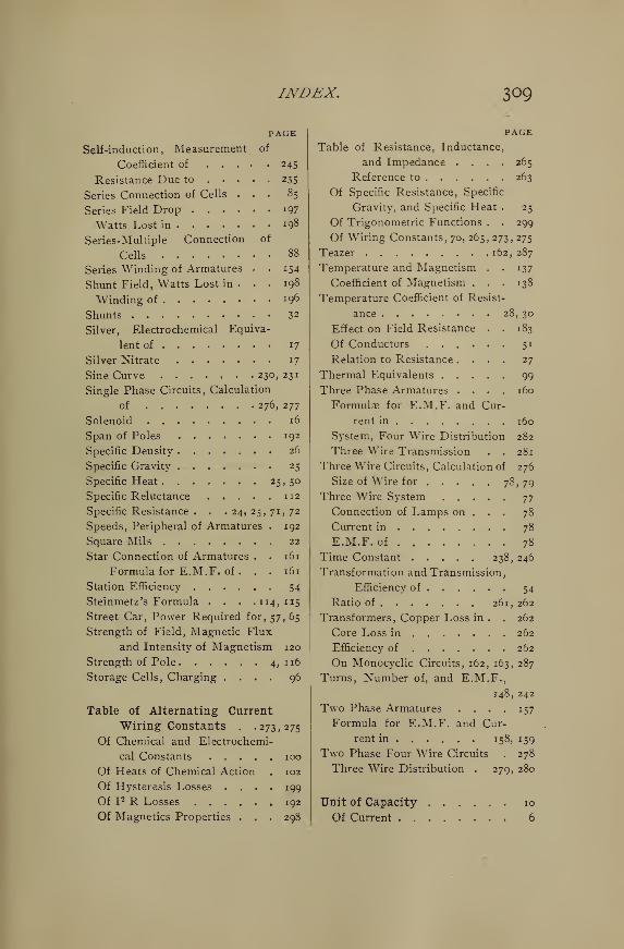
INDEX. 309
PAGE
Self-induction, Measurement of
Coefficient of 245
Resistance Due to 235
Series Connection of Cells ... 85
Series Field Drop 197
Watts Lost in 198
Series-Multiple Connection of
Cells 88
Series Winding of Armatures . .154Shunt Field, Watts Lost in . . . 198
Winding of *96
Shunts 32
Silver, Electrochemical Equiva-
lent of 17
Silver Nitrate 17
Sine Curve ...... .230,231
Single Phase Circuits, Calculation
of 276, 277
Solenoid 16
Span of Poles 192
Specific Density 26
Specific Gravity ....... 25
Specific Heat 25, 50
Specific Reluctance 112
Specific Resistance . . . 24, 25, 71, 72
Speeds, Peripheral of Armatures . 192
Square Mils 22
Star Connection of Armatures . . 161
Formula for E.M.F. of . . . 161
Station Efficiency 54
Steinmetz's Formula . . . . 114, 115
Street Car, Power Required for, 57, 65
Strength of Field, Magnetic Flux
and Intensity of Magnetism 120
Strength of Pole 4, 116
Storage Cells, Charging .... 96
Table of Alternating Current
Wiring Constants . .273,275
Of Chemical and Electrochemi-
cal Constants 100
Of Heats of Chemical Action . 102
Of Hysteresis Losses .... 199
Of I 2 R Losses 192
Of Magnetics Properties . . . 298
PAGE
Table of Resistance, Inductance,
and Impedance .... 265
Reference to 263
Of Specific Resistance, Specific
Gravity, and Specific Heat . 25
Of Trigonometric Functions . . 299
Of Wiring Constants, 70, 265, 273, 275
Teazer 162, 287
Temperature and Magnetism . . 137
Coefficient of Magnetism . . . 138
Temperature Coefficient of Resist-
ance 28, 30
Effect on Field Resistance . . 183
Of Conductors 51
Relation to Resistance .... 27
Thermal Equivalents 99
Three Phase Armatures .... 160
Formulae for E.M.F. and Cur-
rent in 160
System, Four Wire Distribution 282
Three Wire Transmission . . 281
Three Wire Circuits, Calculation of 276
Size of Wire for 78, 79Three Wire System jj
Connection of Lamps on . . . 78
Current in 78
E.M.F. of 78
Time Constant 238, 246
Transformation and Transmission,
Efficiency of 54
Ratio of 261, 262
Transformers, Copper Loss in . . 262
Core Loss in 262
Efficiency of 262
On Monocyclic Circuits, 162, 163, 287
Turns, Number of, and E.M.F.,
148, 242
Two Phase Armatures .... 157
Formula for E.M.F. and Cur-
rent in 158, 159
Two Phase Four Wire Circuits . 278
Three Wire Distribution . 279, 280
Unit of Capacity 10
Of Current 6
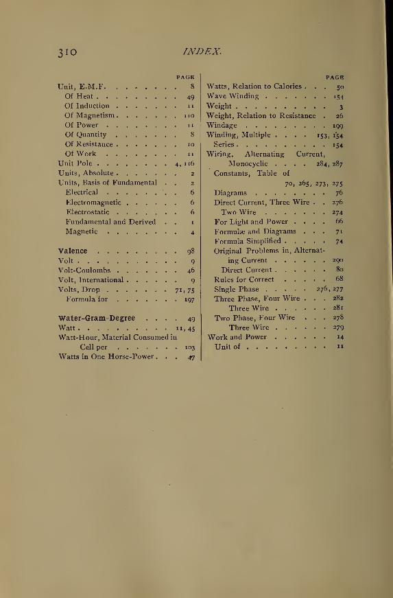
3io INDEX.
PAGE
Unit, E.M.F. ..*.... 8
Of Heat 49
Of Induction nOf Magnetism noOf Power nOf Quantity 8
Of Resistance io
Of Work ii
Unit Pole 4, 116
Units, Absolute 2
Units, Basis of Fundamental . . 2
Electrical '.. 6
Electromagnetic 6
Electrostatic 6
Fundamental and Derived . . 1
Magnetic 4
Valence 98
Volt 9
Volt-Coulombs 46
Volt, International 9
Volts, Drop 7i)7S
Formula for 197
Water-Gram-Degree .... 49
Watt n,45Watt-Hour, Material Consumed in
Cell per 103
Watts in One Horse-Power ... 47
PAGEWatts, Relation to Calories ... 50
Wave Winding 154
Weight 3
Weight, Relation to Resistance . 26
Windage 199
Winding, Multiple .... 153, 1*54
Series 154
Wiring, Alternating Current,
Monocyclic .... 284, 287
Constants, Table of
70, 265, 273, 275
Diagrams 76
Direct Current, Three Wire . . 276
Two Wire 274
For Light and Power .... 66
Formulae and Diagrams ... 71
Formula Simplified 74
Original Problems in, Alternat-
ing Current 290
Direct Current 80
Rules for Correct 68
Single Phase 276, 277
Three Phase, Four Wire ... 282
Three Wire 281
Two Phase, Four Wire ... 278
Three Wire 279
Work and Power 14
Unit of «
LIST OF WORKSON
Electrical SciencePUBLISHED AND FOR SALE BY
D. VAN NOSTRAND COMPANY23 Murray & 27 Warren Streets
NEW YORK
ABBOTT, A. T. The Electrical Transmission of Energy. A Manual for the
Design of Electrical Circuits. Second edition, revised. Fully illustrated.
8vo, cloth $4.50
ARNOLD, E. Armature Windings of Direct-current Dynamos. Extension andApplication of a General Winding Rule. Translated from the original Germanby Francis B. DeGress, M. E. With numerous illustrations, (In Press.)
ATKINSON, PROF. A. A. Electrical and Magnetic Calculations. . . . $1.50
ATKINSON, PHILIP. The Elements of Dynamic Electricity and Magnet-
ism. 12m, cloth £2.00
Elements of Electric Lighting, including Electric Generation, Measurement,
Storage, and Distribution. Ninth edition, fully revised and new matter added.
Illustrated. 8vo, cloth, $1.50
^ Power Transmitted by Electricity and applied by the Electric Motor, includ-
ing Electric Railway Construction. Fourth edition, fully revised and new mat-
ter added. Illustrated. 12mo, cloth, $2.00
BADT. F. B. Dynamo Tender's Hand-book. 70 Illustrations. 16mo, cloth, $1.00
Electric Transmission Hand-book. Illustrations and Tables. 16mo, cloth,
$1.00
Incandescent Wiring Hand-Book. Illustrations and Tables. 12mo, cloth,
$1.00
Bell Hanger's Hand-book. Illustrated. 12mo, cloth, $1.00
BIGGS. C. H. W. First Principles of Electricity and Magnetism. A book for
beginners in practical work. With about 350 diagrams and figures. Illus-
trated. 12mo, cloth, $2.00
BLAKESLEY. T. HE. Alternating Currents of Electricity. For the Use of Stu-
dents and Engineers. Third edition, enlarged. 12mo, cloth, $1.50
BONNET, O. E. The Electro-Plater's Hand Book. A Manual for Amateurs
and Young Students on Electro-Metallurgy. 60 Illustrations. 12mo, cloth, $1.20
MOTTONE, S. R. Electrical Instrument-making for Amateurs. A Practical
Hand-book. Sixth edition. Enlarged by a chapter on "The Telephone."
With 48 Illustrations. 12mo, cloth, $0.50
Electric Bells, and all about them. A Practical Book for Practical Men.With over 100 Illustrations. 12mo, Cloth $0.50
The Dynamo : How Made and How Used. A Book for Amateurs. Sixth edi-
tion. 100 Illustrations. 12mo, cloth, $0.90
Electro-motors : How Made and How Used. A Hand-book for Amateurs andPractical Men. Illustrated. 12mo, cloth, $0.75
BFBIER. E. T. Questions and Answers about Electricity. A First Book for
Beginners. 12mo, cloth, $0.50
CARTER, E. T. Motive Power and Gearing for Electrical Machinery ; a treatise
on the theory and practice of the mechanical equipment of power stations for
electric supply and for electric traction. Illustrated. 8vo, cloth, $5.00
CROCKER, F. B., and S. S. WHEELER. The Practical Management of
Dynamos and Motors. Eleventh thousand. Illustrated. 12mo, cloth, . . $1.00
CROCKER, F. B. Electric Lighting. Vol. I, The Generating Plant. 8vo,
cloth. Illustrated, $3.00
Volume II. Distributing Systems and Lamps. 8vo, cloth. Illustrated, . $3.00
DYNAMIC EEECTRICITY. Its Modern Use and Measurement, chiefly in its
application to Electric Lighting and Telegraphy, including: 1. Some Points in
Electric Lighting, by Dr. John Hopkinson. 2. On the Treatment of Electricity
for Commercial Purposes, by J. N. Schoolbred. 3. Electric Light Arithmetic, byR. E. Day, M. E. Fourth edition. 18mo, boards. (No. 71 Van Nostrand's
Science Series.), $0.50
EWIJfO, J. A. Magnetic Induction in Iron and Other Metals. Second issue.
Illustrated. 8vo, cloth, $4.00
FLEMING. Prof. J. A. The Alternate-Current Transformer in Theory andPractice. Vol. 1 : The Induction of Electric Currents. 500 pp. New edition.
Illustrated. 8vo, cloth, $5.00
Vol. II: The Utilization of Induced Currents. 594 pp. Illustrated. 8vo,cloth $5.00
FOSTER, HORATIO A. (with the collaboration of eminent specialists).
Electrical Engineers' Pocket-book. 1000 pp. Illustrated with many cuts anddiagrams. Pocket size, limp leather, with flap • $5.00
GORE, Br. GEORGE. The Art of Electrolytic Separation of Metals (Theo-
retical and Practical). Illustrated. 8vo, cloth, . . $3.50
GUY, ARTHUR F. Electric Light and Power, giving the Result of Practical
Experience in Central-station Work. 8vo, cloth. Illustrated, $2.50
HASKINS, C. H. The Galvanometer and its Uses. A Manual for Electricians
and Students. Fourth edition, revised. 12mo, morocco, . . $1.50
Transformers ; Their Theory, Construction, and Application Simplified. Illus-
trated. 12mo, cloth, $1.25
HAWKINS, C. C, M. A., A. I. E. E., and WALLIS, F., A. I. E. E. TheDynamo ; its Theory, Design, and Manufacture. 190 Illustrations. 8vo, cloth,
$3.00
MA ¥, ALFRED. Principles of Alternate-Current Working. 12mo, cloth. Illus-
trated, $2.00
HOBBS, W. R. P. The Arithmetic of Electrical Measurements. With numer.ous examples, fully worked. New edition. 12mo, cloth, $0.50
HOSPITALIER. E. Polyphased Alternating Currents. Illustrated. 8vo,
cloth, $1.40
IjrotJCTIOar COILS : How Made and How Used. Tenth edition. 16mo, cloth.
(No. 53 Van Nostrand's Science Series.), $0.50
INCAXDESCEJfT ELECTRIC LIGHTING: A Practical Description of
the Edison System, by H. Latimer. To which is added The Design and Opera-
tion of Incandescent Stations, by C. J. Field ; a Description of the Edison Elec-
trolyte Meter, by A. E. Kennelly ; and a Paper on the Maximum Efficiency of
Incandescent Lamps, by T. W. Howells. Fifth edition. Illustrated. 16mo,
cloth. (No. 57 Van Nostrand's Series.), $0.50
JEHL. FRAXCIS. Member A. I. E. E. The manufacture of Carbons for Elec-
tric Lighting and other purposes. A Practical Hand-book, giving a complete
description of the art of making carbons, electros, etc. The various gas gene-
rators and furnaces used in carbonising, with a plan for a model factory. Illus-
trated with numerous diagrams, tables, and folding plates. 8vo, cloth. Illus-
trated, $4.00
EAPP, OISBERT, C. E. Electric Transmission of Energy and its Transforma-
tion, Subdivision, and Distribution. A Practical Hand-book. Fourth edition,
revised. 12mo, cloth $3.50
Alternate-Current Machinery. 190 pages. Illustrated. (No. % Van Nos-
trand's Science Series.), $0.50
Dynamos, Alternators, and Transformers. Illustrated. 8vo, cloth, . . . $4.00
KEMPE. H. R. The Electrical Engineer's Pocket-book ; Modern Rules, Formulae,
Tables, and Data. 32mo, leather, $1.75
KEXXELLY. A. E. Theoretical Elements of Electro-dynamic Machinery. Vol.
I. Illustrated. 8vo, cloth, $1.50
KILGOIR, M. H., and SWAJf, H., and BIGGS. C. H. W. Electrical Dis-
tribution : Its Theory and Practice. Illustrated. 8vo, cloth, $4.00
LEVY, C. L. Electric Light Primer. A simple and comprehensive digest of all
the most important facts connected with the running of the dynamo and elec-
trie lights, with precautions for safety. For the use of persons whose duty it is
to look after the plant. 8vo, paper, $0.50
LOCKWOOD, T. D. Electricity, Magnetism, and Electro-telegraphy. A Prac-
tical Guide and Hand-book of General Information for Electrical Students,
Operators, and Inspectors. Revised edition. 8vo, cloth. Profusely Illus-
trated, $2.50
LODGE, PROF. OLIVER J. Signalling Across Space Without Wires : being
a description of Hertz and his successors. Third edition. Illustrated. 8vo,
cloth, $2.00
LORIXG. A. E. A Hand-book of the Electro-magnetic Telegraph. Fourth edi-
tion, revised. 16mo, cloth. (No. 39 Van Nostrand's Science Series,), . . . $0.50
MANSFIELD, A. N. Electromagnets ; Their Design and Construction. 16mo,cloth. (No. 64 Van Nostrand's Science Series.) $0.50
MORROW, J. T., and REID, T. Arithmetic of Magnetism and Electricity.
12mo, cloth, $1 00
MUNRO, JOHN, C. E., and JAM1ESON, ANDREW, €. E. A Pocket-book of Electrical Rules and Tables, for the use of Electricians and Engineers.
Fifteenth edition, revised. With numerous diagrams. Pocket size, leather, .$2.50
CIPHER, FRANCIS E., A. M. Theory of Magnetic Measurements, with anAppendix on the Method of Least Squares. 12mo, cloth, $1.00
OHM, Dr. O. S. The Galvanic Circuit Investigated Mathematically. Berlin,
1827. Translated by William Francis. With Preface and Notes by the Editor,
Thos. D. Lockwood. 16mo, cloth. (No. 102 Van Nostrand's Science Series.), . $0.50
OUDIX, MAURICE A. Standard Polyphase Apparatus and Systems, con-
taining numerous photo-reproductions, diagrams, and tables. Third edition,
revised. 8vo, cloth, illustrated, $3.00
y
PALAZ, A., Sc. D. A Treatise on Industrial Photometry, with special appli-
cation to Electric Lighting. Authorized translation from the French by GeorgeW. Patterson, Jr. Second edition, revised. 8vo, cloth. Illustrated, .... $4.00
PARSHALL, H. F., and HOBART, H. M. Armature Windings of Elec-
tric Machines. With 140 full-page plates, 65 tables, and 165 pages of descriptive
letter-press. 4to, cloth,:
$7.50
PERRIXE, F. A. C, A. M., D. Sc. Conductors for Electrical Distribution
;
their Materials and Manufacture, the Calculation of Circuits, Pole Line Con-
struction, Underground Working and other uses. 8vo, cloth. Illustrated. (In
Press.)
PLASTTE, GASTOJf. The Storage of Electrical Energy, and Researches in the
Effects created by Currents combining Quantity with High Tension. Translated
from the French by Paul B. Elwell. 89 Illustrations. 8vo, cloth, $4.00
POPE, F. Ii. Modern Practice of the Electric Telegraph. A Hand-book for
Electricians and Operators. An entirely new work, revised and enlarged, andbrought up to date throughout. Illustrated. 8vo, cloth, $1.50
POOLE, J. The Practical Telephone Hand-book. Illustrated. 8vo, cloth, . $1.50
PRITCHARD, O. G. The Manufacture of Electric Light Carbons. Illustrated.
8vo, paper, $0.60
PREECE, W. H., and STUBBS, A. J. Manual of Telephony. Illustrated.
12mo, cloth, $4.50
RAM, GILBERT S. The Incandescent Lamp and its Manufacture. 8vo,
cloth, $3.00
RANDALL, J. E. A Practical Treatise on the Incandescent Lamp. Illus-
trated. 16mo, cloth, $0.50
RUSSELL, STUART A. Electric-light Cables and the Distribution of Elec-
tricity. Second edition, revised. Illustrated. 8vo, cloth, $3.00
SALOMONS, Sir DAVID, M. A. Electric-light Installations. Vol. I. Man-
agement of Accumulators. A Practical Hand-book. Eighth edition, revised
and enlarged. 12mo, cloth. Illustrated $1.50
4
SALOMONS, Sir DAVID, M. A. fol. II. : Apparatus $2.23
Vol. III. : Application $1.50
SCHEL.LEN, Dr. H. Magneto-electric and Dynamo-electric Machines : Their
Construction and Practical Application to Electric Lighting and the Trans-
mission of Power. Translated from the third German edition by N. S.
Keith and Percy Neymann. Ph. D. With very large Additions and Notes re-
lating to American Machines, by N. S. Keith. Vol. I, with 353 Illustrations.
Second edition $5.00
SHELDON, PROF. S., Ph. D., and HOBART, MASON, B. S. DynamoElectric Machinery : Its Construction, Design and Operation. Direct Current
Machines. Second edition. 8vo, cloth. Illustrated, net, $2.50
SEOANE, Prof. T. O'CONOR. Standard Electrical Dictionary. 300 Illus-
trations. 8vo, cloth, $3.00
SXELL, ALBION" T. Electric Motive Power : The Transmission and Distri-
bution of Electric Power by Continuous and Alternate Currents. With a Sec-
tion on the Applications of Electricity to Mining Work. Second edition. 8vo,
cloth. Illustrated, $4.00
SWOOPE, C. W. Lessons in Practical Electricity : Principles, Experiments
and Arithmetical Problems. 8vo, cloth. Illustrated net, $2.00
THOM, C, and JONES, W. H. Telegraphic Connections, embracing recent
methods in Quadruplex Telegraphy. 8vo, cloth. Twenty colored plates, . $1.50
THOMPSON, EDWARD P. How to Make Inventions; or, Inventing as a
Science and an Art. An Inventor's Guide. Illustrated. 8vo, paper, . . .$1.00
THOMPSON, Prof. S. P. Dynamo -electric Machinery. With an Introduc-
tion and Notes by Frank L. Pope and H. R. Butler. Fourth edition. Fully Il-
lustrated. (No. 66 Van Nostrand's Science Series.), $0.50
Recent Progress in Dynamo-electric Machines. Being a Supplement to " Dy-
namo-electric Machinery." Illustrated. 16mo, cloth. (No. 75 Van Nostrand's
Science Series.), $0.50
TREVERT, E. Practical Directions for Armature and Field-magnet Winding.
12mo, cloth. Illustrated, $1.50
TUMLIRZ, Dr. Potential, and its application to the explanation of Electrical
Phenomena. Translated by D. Robertson, M. D. 12mo, cloth, $1.25
TUNZEEMANN, G. W. de. Electricity in Modern Life. Illustrated. 12mo,
cloth, $1.25
URQUHART, J. W. Dynamo Construction. A Practical Hand-book for the
Use of Engineer Constructors and Electricians in Charge. Illustrated. 12mo,
cloth, $3.00
WATT, ALEXANDER. Electro-Deposition. A Practical Treatise on the
Electrolysis of Gold, Silver, Copper, Nickel, and other Metals, with Descriptions
of Voltaic Batteries, Magneto and Dynamo-Electric Machines, Thermopiles,
and of the Materials and Processes used in every Department of the Art, andseveral chapters on Electro-Metallurgy. With numerous illustrations. Third
edition, revised and corrected. Crown, 8vo, 568 pages, $3.50
Electro-Metallurgy Practically Treated. Eleventh edition, considerably en-
larged. 12mo, cloth, $1.0Q
5
WALKER, FREDERICK. Practical Dynamo-building for Amateurs. Howto Wind for any Output. Illustrated. 16mo, cloth. (No. 98 Van Nostrand's
Science Series.), .$0.50
WALKER, SYDNEY F. Electricity in our Homes and Workshops. A Prac-
tical Treatise on Auxiliary Electrical Apparatus. Illustrated. 12mo, cloth, . $2.00
WEBB, H. Ij. A Practical Guide to the Testing of Insulated Wires and Cables.
Illustrated. 12mo, cloth, $1.00
WEEKES, R. W. The Design of Alternate Current Transformers. Illustrated.
12mo, cloth $1.00
WEYMOUTH, F. MARTEN. Drum Armatures and Commutators. (Theoryand Practice.) A complete treatise on the theory and construction of drum-winding, and of commutators for closed-coil armatures, together with a full
resume of some of the principal points involved in their design ; and an exposi-
tion of armature reactions and sparking. 8vo, cloth. Illustrated, $3.00
WIIiKINSON, H. D. Submarine Cable-Laying, Repairing, and Testing. 8vo,
cloth, $5.00
WORDINGHAM. HENRY C. Central Electrical Stations; their Design,
Organization, and Management. With 136 diagrams and folding plates. 8vo,
cloth. Illustrated, net $7.50
WORMELL, R. Electricity in the Service of Man. A Popular and Practical
Treatise on the Application of Electricity in Modern Life. From the German,
and edited, with copious additions, by R. Wormell, and an Introduction by Prof.
J. Perry. With nearly 850 Illustrations. 8vo, cloth, $3.00
YOUNG, J. ELTON. Electrical Testing for Telegraph Engineers. With Ap-
pendices consisting of Tables. 8vo, cloth. Illustrated, $4.00
*** A General Catalogue—80 pages—of Works in all branches of
Electrical Science furnished gratis on application,
1
APR 4 1913